GPSMAP
®
6000/7000 Series Installation Instructions
WARNING
See the Important Safety and Product Information guide in the product box for product warnings and other important information.
CAutIoN
Always wear safety goggles, ear protection, and a dust mask when drilling, cutting, or sanding.
Notice
When drilling or cutting, always check what is on the opposite side of the surface to avoid damaging your boat.
The GPSMAP 6000/7000 series chartplotter and GPS antenna must be properly installed according to the following instructions. You need the
appropriate fasteners, tools, and mounts listed in each section. These items are available at most marine dealers.
Contact Garmin
®
Product Support if you have any questions while installing your GPSMAP 6000/7000 series chartplotter. In the USA, go to
www.garmin.com/support, or contact Garmin USA by phone at (913) 397.8200 or (800) 800.1020. In the UK, contact Garmin (Europe) Ltd. by
phone at 0808 2380000. In Europe, go to www.garmin.com/support and click Contact Support for in-country support information, or contact
Garmin (Europe) Ltd. by phone at +44 (0) 870.8501241.
Before installing your GPSMAP 6000/7000 series chartplotter, conrm that the package contains the items listed on the box. If any parts are
missing, contact your Garmin dealer immediately.
Product Registration
Help us better support you by completing our online registration today. Go to http://my.garmin.com. Keep the original sales receipt, or a
photocopy, in a safe place.
For future reference, write the serial numbers assigned to your GPSMAP 6000/7000 series chartplotter and GPS antenna in the space provided.
The serial numbers are located on a sticker on the back of each device.
Chartplotter serial number:
GPS antenna serial number:
to install the GPSMAP 6000/7000 series chartplotter, you must:
1. MounttheGPSMAP6000/7000serieschartplotter(page2).
2. MounttheGPSantenna(page4).
3. ConnecttheGPSMAP6000/7000serieschartplottertopower(page7).
4. ConnecttheGPSMAP6000/7000serieschartplotterandtheGPSantennatoanexistingNMEA2000networkorcreateasimpleNMEA
2000network(page8).
5. Ensurethatthechartplottersoftwareisup-to-date(page17).
the following additional installation options are not necessary in order to use the GPSMAP 6000/7000 chartplotter. they have
been included for your convenience:
• ConnectingthechartplottertootherGarminMarineNetworkcompatibledevices,suchasasounderoraradar(page9).
• ConnectingthechartplottertoaGPS17orGPS17HVSantenna(page15).
• ConnectingthechartplottertootherNMEA0183-compatibledevicessuchasaVHFradiowithDSC(page12).
• Connectingthechartplottertoanexternalalarm(page15).
• Connectingthechartplottertoavideoinputsource,toaPC,ortoanexternalvideomonitor(page16).
April2012 PartNumber190-01495-02Rev.B PrintedinTaiwan
2 GPSMAP 6000/7000 Series Installation Instructions
Mounting the GPSMAP 6000/7000 Series Chartplotter
You can mount the GPSMAP 6000/7000 series chartplotters using one of two methods. You can use the included bracket to bail mount the
chartplotter, or you can use the included template and hardware to ush mount the chartplotter.
Mount the GPSMAP 6000/7000 series chartplotter in a location that provides a clear, glare-free view of the display and easy operation of the
controls or touch screen.
Note: You cannot bail mount the GPSMAP 7015/7215 chartplotters. Because of the larger size of these devices, you must ush mount a
GPSMAP 7015 or a GPSMAP 7215 chartplotter.
Bail Mounting the GPSMAP 6000/7000 Series Chartplotter
Use the included bracket to bail mount a GPSMAP 6008, 6208, 6012, 6212, 7012, or a GPSMAP 7212 chartplotter.
tools required (not included):
• Drillanddrillbits
• Pencil
• Mountinghardware(screwsornuts,washers,andbolts)
Note: The bail-mounting hardware (screws or nuts, washers, and bolts) is not included. The holes on the bail mount are
5
/
16
in. (7.9 mm) in
diameter. Choose mounting hardware that ts the holes in the bail mount and securely attaches it to your specic mounting surface. The size of
the drill bit required depends on the mounting hardware you use.
to install the bail-mount bracket:
Note: You cannot bail mount the GPSMAP 7015/7215 chartplotters. Because of the larger size of these devices, you must ush mount a
GPSMAP 7015 or a GPSMAP 7215 chartplotter.
1. Usingthebailmountasatemplate,markthelocationofthefourmountingholes.Besuretoleaveatleast5in.(12.7cm)ofclearance
behindthe6000/7000serieschartplotterforthewiring.
NotE:Toavoidinterference,mountGPSMAP6008/6208chartplotters15in.(38.1cm),GPSMAP6012/6212chartplotters16in.(40.6cm),
andGPSMAP7012/7212chartplotters25in.(63.5cm)fromamagneticcompass.
2. Usinganappropriately-sizeddrillbit,drillthepilotholesforyourmountinghardware.
3. Securethebailmounttothesurfacewithscrewsandwashers.
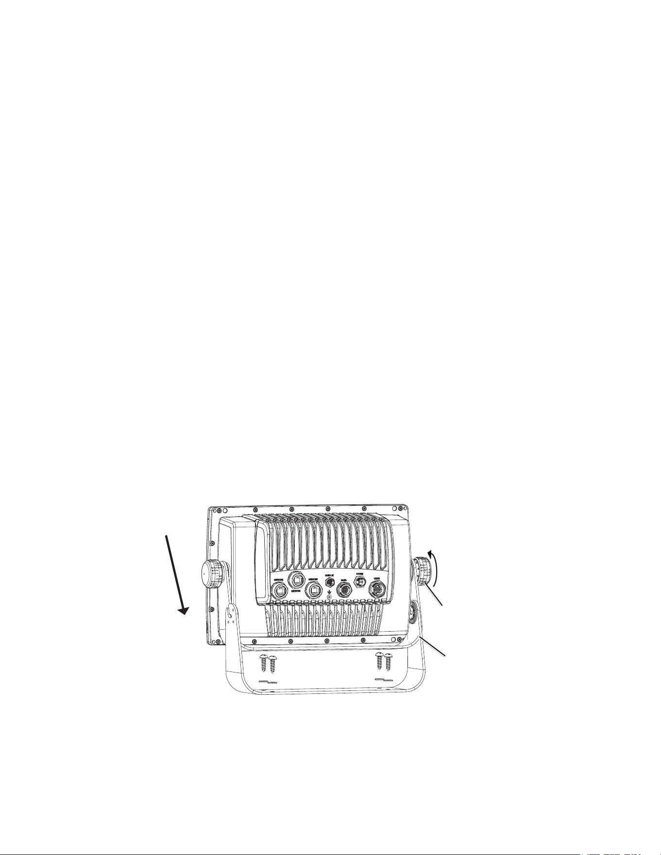
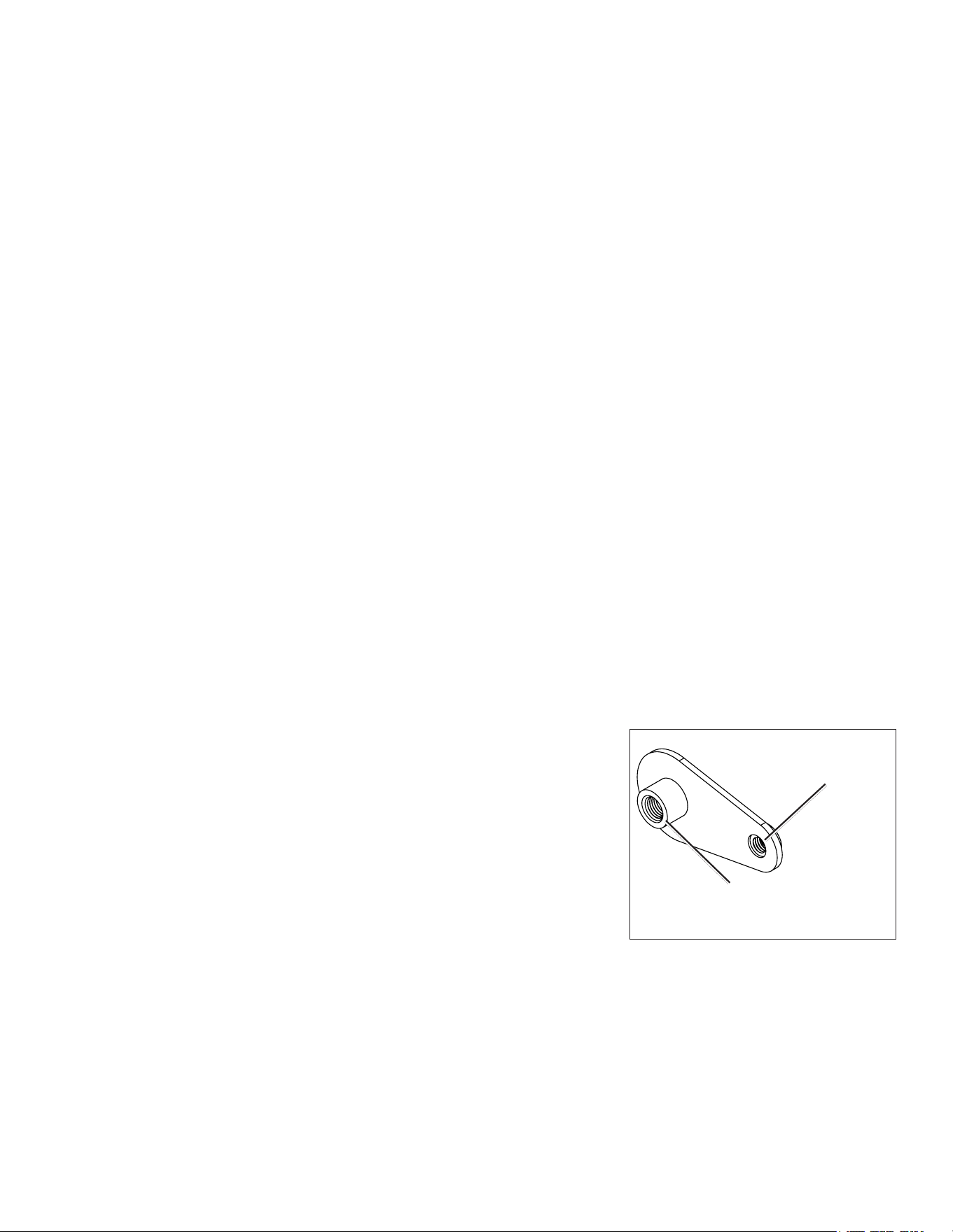
to install the GPSMAP 6000/7000 series chartplotter on the bail-mount bracket:
1. LooselyattachthemountingknobstotheGPSMAP6000/7000serieschartplotter.
2. Slidethechartplotterontothebailmount,andtightenthemountingknobs.
Bail-mount bracket
Mounting knob
Installing a GPSMAP 6000/7000 Series Chartplotter on the Bail-mount Bracket
GPSMAP 6000/7000 Series Installation Instructions 3
Flush Mounting the GPSMAP 6000/7000 Series Chartplotter
Hardware (included):
• Flush-mounttemplate
• Rubbergasket
• Fourush-mountnut-plates
• Four60mmM3× 0.5screws(tosecurethenutplatetothe
mountingsurface)
• FourM4× 0.7screws(tosecurethechartplottertothenutplate)
• Four7mmnylonwashers(fortheM4×0.7screws)
tools required (not included):
• Jigsaw
• Scissors
• Drill
• Drillbits—
3
/
8
in.(9.5mm),
9
/
32
in.(7.2mm),and
9
/
64
in.(3.5mm)
• Number2Phillipsscrewdriver
• Centerpunchandhammer
• Fileandsandpaper
1. Theush-mounttemplateisincludedintheproductbox.Trimthetemplateandensurethatitwilltinthelocationatwhichyouwanttoush
mountthechartplotter.
NotES:
• Ensurethatthesurfaceonwhichyoumountthechartplotterhasenoughopenspacebehindittoaccommodatethechartplotterandthe
connectedwires.Refertothediagramontheush-mounttemplatefortheclearance-spaceneededbyyourchartplotter.
• Ensurethatthereisatleast
1
/
2
in.(13mm)ofspaceontherightsideofthechartplottertoaccesstheSDcarddoor,asindicatedonthe
ush-mounttemplate.
• Ensurethatenoughventilationispresentbehindthemountingsurfacetocreatesufcientairowtopreventthechartplotterfrom
overheating.
• Toavoidinterference,mountGPSMAP6008/6208chartplotters15in.(38.1cm),GPSMAP6012/6212chartplotters16in.(40.6cm),
GPSMAP7012/7212chartplotters25in.(63.5cm)and7015/7215chartplotters17in.(43.2cm)fromamagneticcompass.
2. Theush-mounttemplatehasadhesiveontheback.Removetheprotectivelinerandapplythetemplatetothelocationatwhichyouwantto
ushmountthechartplotter.
3. Usinga
3
/
8
in.(9.5mm)drillbit,drilloneormoreofthefourpilotholesinsidethecornerofthetemplatetobegincuttingthemounting
surface.
4. Usingajigsaw,cutthemountingsurfacealongtheinsideofthesolidlineindicatedontheush-mounttemplate.Usealeandsandpaperto
renethesizeofthehole.Be very careful when cutting this hole. there is only a small amount of clearance between the case and
the mounting holes.
5. Placethechartplotterintheholeandensurethatthemountingholesonthechartplotterlineupwiththelarger
9
/
32
in.(7.2mm)holesonthe
ush-mounttemplateaftercutting,sanding,andlingthehole.Iftheydonotlineup,marknewlocationsforthelargerholes.
6. Usingacenterpunch,indentthecenterofeachofthelarger
9
/
32
in.(7.2mm)mounting-holelocations.
7. Usinga
9
/
32
in.(7.2mm)drillbit,drillthefourlargerholes.
8. Startinginonecornerofthetemplate,placeanutplateoverthelargerholeyoudrilledinstep
7.Ensurethatthesmaller
9
/
64
in.(3.5mm)holeonthenutplatelinesupwiththesmallerhole
onthetemplate.Iftheydonotlineup,markanewlocationforthesmallerhole.Repeatthis
stepforeachcornerofthetemplate.
9. Usingacenterpunch,indentthecenterofeachofthesmaller
9
/
64
in.(3.5mm)mounting-hole
locations.
10.Removetheush-mounttemplatefromthemountingsurface.
11.Startinginonecornerofthemountinglocation,placeanutplateonthebackofthemounting
surface,liningupthelargeandsmallholes.Theraisedportionofthenutplateshouldtinto
thelargerhole.
12.Securethenutplatetothemountingsurfacebyfasteninganincluded60mmM3×0.5screw
throughthesmaller
9
/
64
in.(3.5mm)hole.
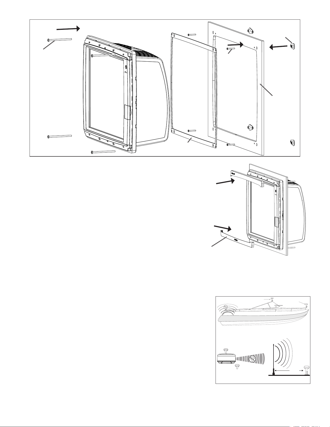
Use the 60 mm M3 × 0.5 screw
to fasten the nut plate to the
mounting surface
Use the 70 mm M4 × 0.7 screw
to fasten the chartplotter to the
nut plate
Flush-mount Nut Plate
4 GPSMAP 6000/7000 Series Installation Instructions
Flush-mounting a GPSMAP 6000 or 7000 Series Chartplotter
Mounting surface
Nut plate (×4)
60 mm M3×0.5
screw (×4)
70 mm M4×0.7
screw (×4)
Rubber gasket
(4 pieces)
13.Repeatsteps11–12foreachnutplateontheremainingthreecornersofthemountingsurface.
14.Installtherubbergasketonthebackofthechartplotter.Thetopandbottomsections
lineupwiththeholes.
15.Ifyouwillnothaveaccesstothebackofthechartplotterafteryoumountit,connect
allnecessarycablestothechartplotterbeforeplacingitintothecutout.
16.Placethechartplotterintothecutout.
17.Securethechartplottertothemountingsurfaceusingtheincluded70mmM4×0.7
screwsand7mmblacknylonwashers.
NotE:Topreventcorrosionofthemetalcontacts,coverunusedconnectors
(page17)withtheattachedweathercaps.
18.Installthemountingcoversbysnappingthemintoplace.
Mounting the GPS Antenna
You can surface mount the GPS antenna, attach it to a standard 1 in. OD pipe-threaded-pole marine mount (14 threads-per-inch—not included),
or install the antenna under berglass.
Select a suitable location for the GPS antenna on your boat. To ensure the best reception, mount the GPS antenna in a location that has a clear,
unobstructed view of the sky in all directions.
• Avoid mounting the GPS antenna where it is shaded by the superstructure of the boat, a
radome antenna, or a mast.
• On a sailboat, avoid mounting the GPS antenna high on the mast to prevent inaccurate
speed readings caused by excessive heeling.
• The GPS antenna provides more-stable readings when located nearer to water level.
• Mount the GPS antenna at least 3 ft. (1 m) away from (preferably above) the path of
any radar beam or a VHF radio antenna.
Temporarily secure the antenna in the preferred mounting location and test it for correct
operation. If you experience interference with other electronics, try a different location. After
you verify correct operation, permanently mount the antenna.
tools required (not included):
• Drillanddrillbits
• Screwdrivers
• Marinesealant(optional)
Mounting covers (×2)
SS BARNETT
Radar
VHF Radio Antenna
3 ft.
(1 m)
Above - best
Below - OK
EMI (Electromagnetic Interference)
from engine components
Best
Better
Good
EMI
GPS Antenna Placement Considerations
GPSMAP 6000/7000 Series Installation Instructions 5
Surface-mounting the GPS Antenna
1. Usethesurface-mountbracketasyourmountingtemplate,usingthefollowingsteps:.
• Useacenterpunchtomarkthethreescrewlocationsonthesurface.
• Useapenciltotracethecable-holeinthecenterofthebracket.
• Setthesurface-mountbracketaside.Donotdrillthroughthesurface-mount
bracket.
2. Drill
1
/
8
in.(3mm)pilotholesatthethreemarkedlocations.
NotE:IfyouaremountingtheGPSantennaonberglass,itisrecommendedtouse
acountersinkbittodrillaclearancecounterborethroughthetopgelcoatlayer(but
nodeeper).Thiswillhelptoavoidcrackinginthegelcoatlayerwhenthescrewsare
tightened.
3. Usea1in.(25mm)holesawtocutthecableholeinthecenter.
4. Placethesealpadonthebottomofthesurface-mountbracket.Makesurethatthescrew
holesalign.
5. UsetheincludedM4screwstoattachthesurface-mountbrackettothemountingsurface.
6. RoutetheNMEA2000cablethroughthe1in.(25mm)cableholeandconnectittotheGPSantenna.
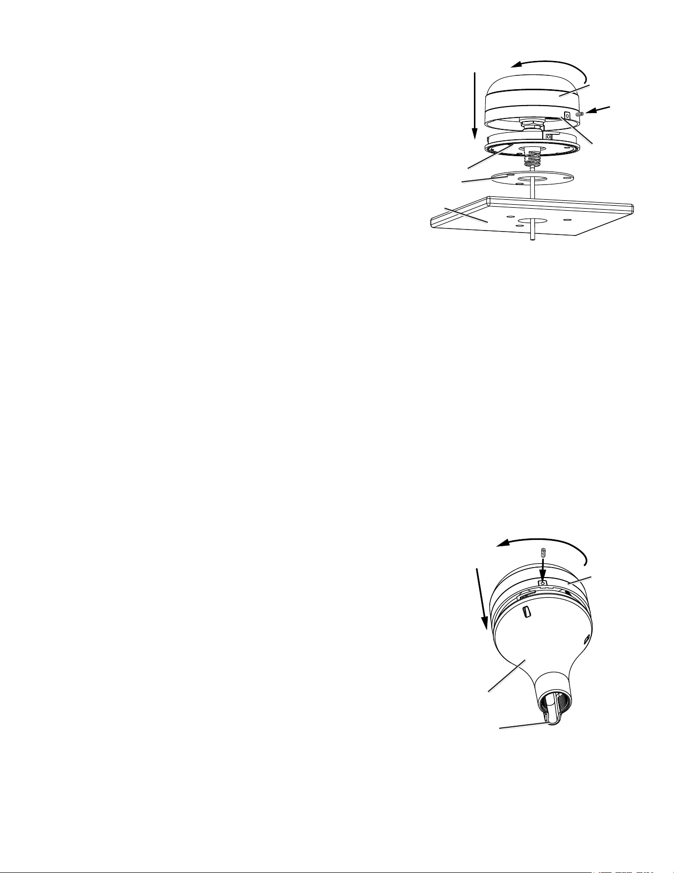
7. MakesurethelargegasketisinplaceonthebottomoftheGPSantenna,placetheantennaonthesurface-mountbracket
➊
,andtwistit
clockwisetolockitinplace
➋
.
8. SecuretheantennatothemountingbracketwiththeincludedM3setscrew
➌
.
9. RoutetheNMEA2000dropcableawayfromsourcesofelectronicinterference,andconnectittoyourNMEA2000network(page8).
Pole Mounting the GPS Antenna
With the pole-mount adapter attached to the GPS antenna, you can install it on a standard 1 in. OD pipe-threaded-pole marine mount
(14 threads per inch—not included). You can run the NMEA 2000 cable through the pole or outside the pole.
to mount the GPS antenna with the cable run outside the pole:
1. RoutetheNMEA2000dropcablethroughthepole-mountadapter,andplacethecableintheverticalslotalongthebaseofthepole-mount
adapter.
2. Threadthepole-mountadapterontoastandard1in.ODpipe-threaded-polemarinemount(14threadsperinch—notincluded).Donot
overtightentheadapter.
3. ConnectaNMEA2000dropcabletotheGPSantenna.
4. PlacetheGPSantennaonthepole-mountadapter
➊
andtwistitclockwisetolockitinplace
➋
.
5. SecuretheantennatotheadapterwiththeincludedM3setscrew
➌
.
6. (Optional)WiththeGPSantennainstalledonthepolemount,lltheremaininggapinthe
verticalcableslotwithamarinesealant.
7. Attachthemarinemounttotheboatifitisnotalreadyattached.
8. Routethecableawayfromsourcesofelectronicinterference,andconnectittoyourNMEA
2000network(page8).
to mount the GPS antenna with the cable run through the pole:
1. Positionastandard1in.ODpipe-threaded-polemarinemount(14threadsperinch—not
included)inthepreferredlocation,andmarktheapproximatecenterofthepole.
2. Drillaholeusinga
3
/
4
in.(19mm)drillbitforthecabletopassthrough.
3. Fastenthemarinemounttotheboat.
4. Threadthepole-mountadapterontothepole.Donotovertightentheadapter.
5. RouteaNMEA2000dropcablethroughthepoleandconnectittotheGPSantenna.
6. PlacetheGPS19xantennaonthepole-mountadapter
➊
andtwistitclockwisetolockitinplace
➋
.
7. SecuretheantennatotheadapterwiththeincludedM3setscrew
➌
.
8. (Optional)WiththeGPS19xinstalledonthepolemount,lltheverticalcableslotwithamarinesealant.
9. RoutetheNMEA2000dropcableawayfromsourcesofelectronicinterference,andconnectittoyourNMEA2000network(page8).
GPS
antenna
Surface-mount
bracket
Seal pad
Mounting
surface
➊
➋
➌
Rubber
gasket
GPS
antenna
Pole-mount
adapter
Vertical cable
slot
➊
➋
➌
6 GPSMAP 6000/7000 Series Installation Instructions
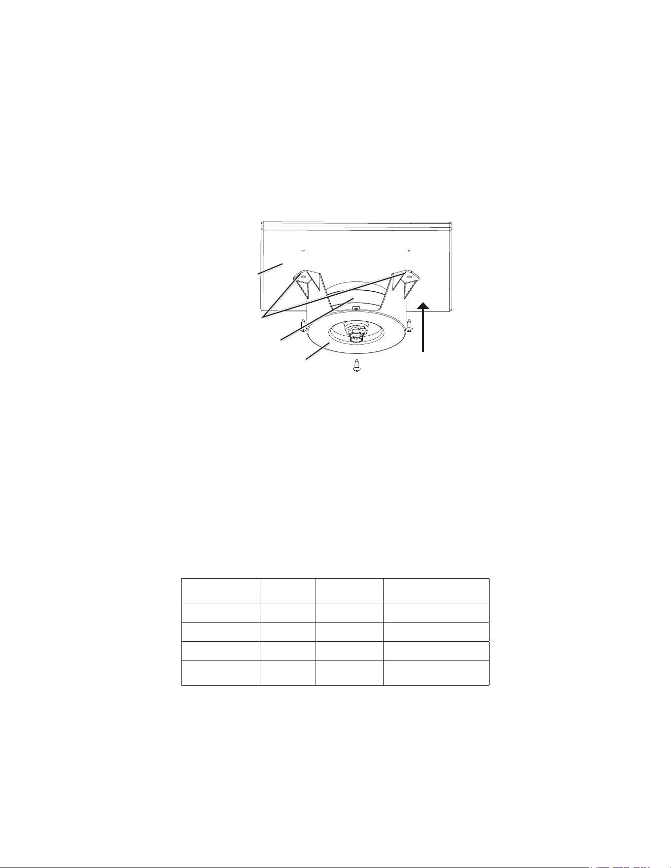
under-deck-mounting the GPS 19x Antenna
The GPS 19x antenna can be mounted under a berglass surface with the adhesive pads attached to the under-deck mounting bracket. The GPS
19x will not acquire satellite signals through metal—you can only use the under-deck mount under a berglass surface.
1. DeterminethelocationontheberglasssurfacewhereyouwanttomounttheGPS19x.
2. Placetheadhesivepadsontheunder-deckmountingbracket.
3. PlacetheGPS19xintheunder-deckmountingbracket.
4. Adheretheunder-deckmountingbrackettothemountingsurface.
5. Securetheunder-deckmounttothemountingsurfacewithscrews.Useextremecaretoensurethatthescrewsdonotpenetratetheupper
surfaceofthedeck.
6. ConnectaNMEA2000dropcabletotheGPS19x.
7. RoutetheNMEA2000dropcableawayfromsourcesofelectronicinterference,andconnectittoyourNMEA2000network(page8).
GPS 19x
antenna
Under-deck-
mounting bracket
Mounting
surface
Adhesive
pads
Installing Cables
The GPSMAP 6000/7000 series chartplotter is packaged with the following cables:
• A two-pin power cable
• A 19-pin NMEA 0183 data cable
• A 17-pin marine video cable (the GPSMAP 7015/7215 chartplotter is packaged with two different marine video cables)
• NMEA 2000 cables and connectors
Installing Locking Rings on the Cables
To help make the cable-routing process easier, the locking rings are packaged separately from the cables. Each locking ring is packaged in a
small bag with a number on the label for easy identication. After you route the cables, use the following table to identify the correct locking
ring for each cable:
Cable Connector
Color
Locking Ring
Number
Replacement Locking
Ring Part Number
Power Red
➀
010-11170-01
NMEA0183 Blue
➁
010-11170-02
Video Yellow
➂
010-11170-00
Video2
(7015/7215only)
Purple
➂
010-11170-00
NoteS:
• The NMEA 2000 cables and connectors come with the locking rings pre-installed. Do not remove the locking ring from a NMEA 2000 cable
while routing the cable.
• Optional Garmin Marine Network components use specialized Garmin Network cables (not included). Each network cable is also
packaged with a separate locking ring, in a bag labeled with a
➃
. A network-cable specic locking ring should not be used with a
GPSMAP 6000/7000 cable.
GPSMAP 6000/7000 Series Installation Instructions 7
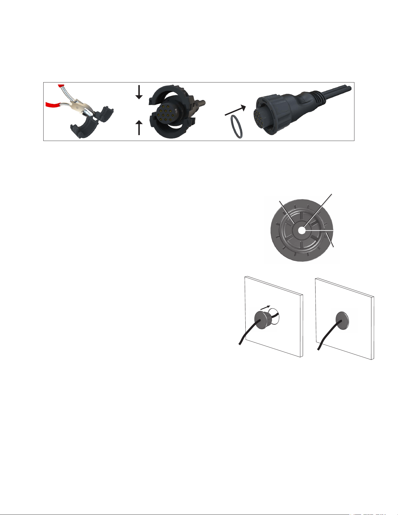
Installing a locking ring on a cable:
1. Routethecableawayfromsourcesofelectronicinterferencesothatthecableconnectorisatthemountinglocationofthechartplotter.
2. Usethetableabovetoidentifythecorrectlockingringforthecable,andlocatethelockingringbagbynumber.
3. Separatethetwohalvesofthelockingring.
4. Alignthetwohalvesofthelockingringoverthecableandsnapthemtogether.
5. InserttheO-ringintotheendoftheconnector.
Installing a Locking Ring
Installing Cable Grommets
Depending on the installation, it may be necessary to drill holes to route the connector end of the GPSMAP cables. Rubber grommets are
provided to cover the cable holes for a nished look. You may not need the grommets in some installations. The grommets do NOT create a
waterproof seal. To create a waterproof seal, apply a marine sealant around the
grommet and cable after installation. Be sure to test the system before installing and
sealing the grommets. Purchase additional grommets from your Garmin dealer or
directly from Garmin at www.garmin.com.
tools Required
• Drill
• 1
1
/
4
in. (31.7 mm) paddle drill bit or hole saw
• Utility knife
• Marine sealant (optional)
to install the cable grommet:
1. Markthelocationwhereyouwanttoroutethecable(power,NMEA0183,NMEA
2000,MarineVideo,orMarineNetwork.)
2. Usinga1
1
/
4
in.(31.7mm)paddledrillbitorholesaw,drilltheinstallationhole.
3. Refertothediagramonpage7fortrimminginstructions.Carefullytrimthecable
holeinthegrommet,asneeded.
4. Routethecabletothechartplotter,andtestthesystem.
5. Spreadthegrommetapartatthesplitandplaceitaroundthecable.
6. Firmlypushthegrommetintotheinstallationholeuntilitisseated.
7. Applymarinesealant,asneeded,toweatherprooftheinstallation-hole(optional).
Wiring the Power Cable
The GPSMAP 6000/7000 series chartplotter must be connected to the power supply for the boat.
1. Routetheincluded2-pinpowercabletotheboatbatteryandtothechartplotter.
2. Connectthepower(red)andground(black)wirestothebatteryterminals.
NotES:
• Use14AWGshieldedwiringforextendedrunsofwiretothepowercable.
• Solderallconnectionsandsealthemwithheat-shrinktubing.
Trim to this line for the
Marine Video cable.
Use this hole (no
trim) for a power,
NMEA 0183,
Marine Network, or
NMEA 2000 cable
Split
8 GPSMAP 6000/7000 Series Installation Instructions
Installing the GPSMAP 6000/7000 Series Chartplotter and the GPS 19x Antenna NMEA
2000 Network Connections
The GPSMAP 6000/7000 series chartplotter is packaged with the necessary NMEA 2000 connectors and cable to either connect a GPSMAP
6000/7000 series chartplotter and a GPS 19x antenna to your existing NMEA 2000 network, or to build a basic NMEA 2000 network. For more
information on NMEA 2000, visit www.garmin.com.
If you are unfamiliar with NMEA 2000, be sure to read the “NMEA 2000 Network Fundamentals” chapter of the Technical Reference for
Garmin NMEA 2000 Products on the included CD or click on the “Manuals” hyperlink on the product page for your chartplotter at
www.garmin.com. For example, www.garmin.com/products/GPSMAP7212/.
Connecting to an Existing NMEA 2000 Network
If your boat already has a NMEA 2000 network installed, use the included T-connectors and drop cable to connect a GPSMAP 6000/7000 series
chartplotter and a GPS 19x antenna to the existing network.
Notice
If you have an existing NMEA 2000 network on your boat, it should already be connected to power. Do not connect the included NMEA 2000
power cable to an existing NMEA 2000 network.
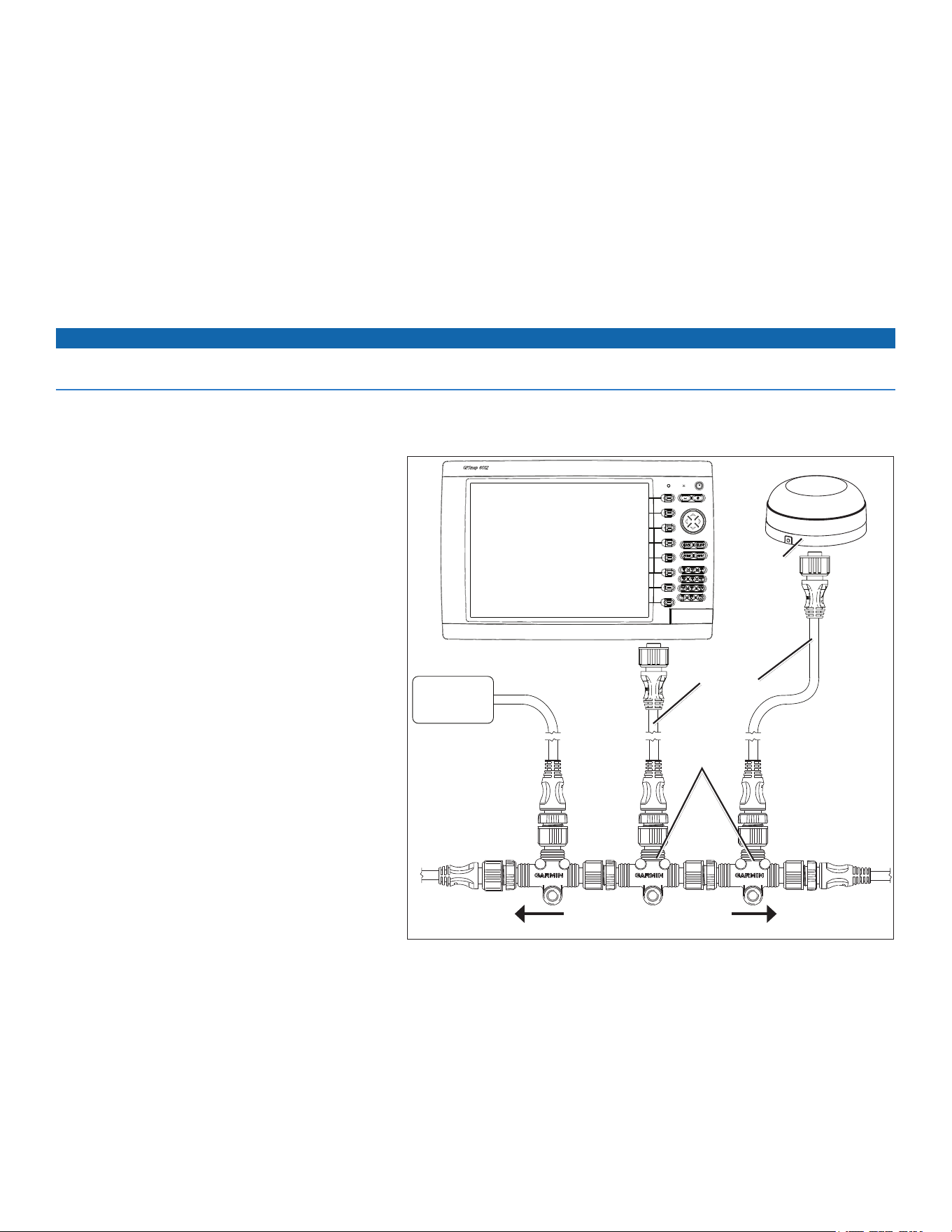
to connect a GPSMAP 6000/7000 series chartplotter and a GPS 19x to your existing NMEA 2000 network:
1. IdentifywhereyouwanttoconnecttheGPSMAP6000/7000serieschartplotterandtheGPS19xtoyourexistingNMEA2000backbone.
2. DisconnectonesideofaNMEA2000T-connectorfrom
thebackbonenearesttothelocationwhereyouwant
toconnectthechartplotter.
ToextendtheNMEA2000backbone(ifnecessary),
connectanappropriateNMEA2000backbone
extensioncable(notincluded)tothesideofthe
T-connectoryoudisconnected.
3. ConnectanincludedT-connectortotheNMEA2000
backbone(forthechartplotter).
4. Routeanincludeddropcabletothechartplotterand
tothetopoftheT-connectoryouaddedtoyourNMEA
2000network.
Iftheincludeddropcableisnotlongenough,youcan
addadropcableextensionupto13ft.(4m).Ifmore
cableisneeded,addanextensiontoyourNMEA2000
backbone,basedontheNMEA2000guidelines.
5. DisconnectonesideofaNMEA2000T-connectorfrom
thebackbonenearesttothelocationwhereyouwant
toconnecttheGPS19xantenna.
ToextendtheNMEA2000backbone(ifneeded),
connectanappropriateNMEA2000backbone
extensioncable(notincluded)tothesideofthe
T-connectoryoudisconnected.
6. ConnectanincludedT-connectorintheNMEA2000
backbone(fortheGPS19xantenna).
7. RouteanincludeddropcablefromtheGPS19x
antennatothetopoftheT-connectoryouaddedto
yourNMEA2000network.
Iftheincludeddropcableisnotlongenough,youcanaddadropcableextensionupto13ft.(4m).Ifmorecableisneeded,addan
extensiontoyourNMEA2000backbone,basedontheNMEA2000guidelines.
NotES:
• Thediagramonpage8showsonlytheNMEA2000dataconnectiontoaGPSMAP6000/7000serieschartplotter.Thechartplottermust
alsobeconnectedtopoweroritwillnotfunction.
• OneGPSantennawillprovidepositiondataforeverydeviceontheNMEA2000network.DonotconnectmultipleGPSantennasifyou
areusingmultiplechartplotters.
Connecting a GPSMAP 6000/7000 Series Chartplotter and a GPS 19x
Antenna to an Existing NMEA 2000 Network
T-connectors
(included)
Drop cables
(included)
Existing NMEA 2000 network
(not included)
GPS 19x
antenna
GPSMAP 6000/7000
series chartplotter
NMEA 2000
device
(not included)
GPSMAP 6000/7000 Series Installation Instructions 9
Creating a Basic NMEA 2000 Network
If your boat does not already have an existing NMEA 2000
network installed, you must create a basic NMEA 2000 network.
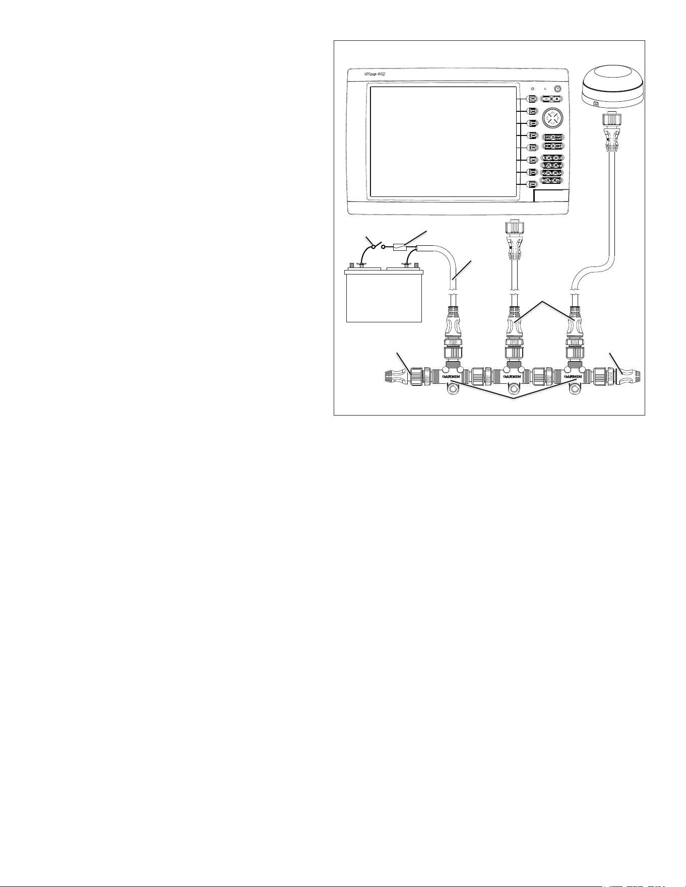
to create a basic NMEA 2000 network:
1. ConnectthethreeincludedT-connectorstogether,sideby
side.
2. Connecttheterminatorstotheendsofthecombined
T-connectors.
3. WiretheincludedNMEA2000powercabletoa12Vdcpower
sourcethroughaswitch.Connectthepowercabletothe
ignitionswitchoftheboatifpossible.
4. ConnecttheNMEA2000powercabletothetopofoneofthe
T-connectors.
5. RouteandconnecttheincludedNMEA2000dropcables
fromtheGPS19xandfromtheGPSMAP6000/7000series
chartplottertothetopsoftheotherT-connectors.
NotES:
• ThediagramshowsonlytheNMEA2000dataconnection
totheGPSMAP6000/7000serieschartplotter.The
chartplottermustalsobeconnectedtopoweroritwillnot
function(page7).
• OneGPSantennawillprovidepositiondataforevery
deviceontheNMEA2000network.Donotconnectmultiple
GPSantennasifyouareusingmultiplechartplotters.
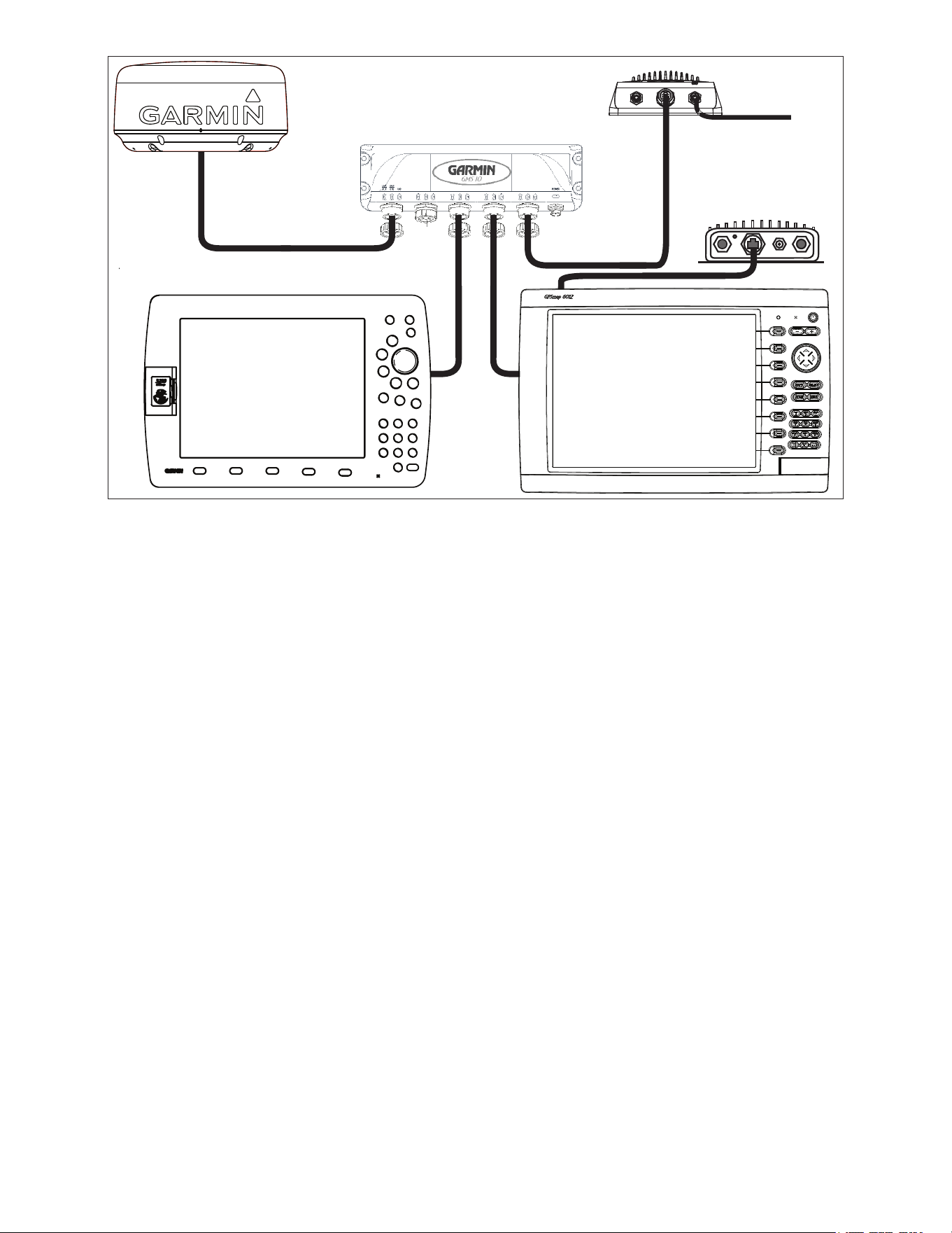
Wiring a Garmin Marine Network
The optional Garmin Marine Network is a plug-and-play system
that allows for high-speed data transfer between multiple Garmin chartplotters and other network-compatible Garmin devices such as a Garmin
sonar unit (GSD 22), or a Garmin radar (GMR™ 18 HD or GMR 1206 xHD). The GPSMAP 6000/7000 series chartplotters have three network
ports that can be used to connect other Garmin network-compatible chartplotters and devices. If the network requires more ports, use a Garmin
Marine Network port extender (GMS 10), or another GPSMAP 6000/7000. Data from each connected component is shared by all the connected
Garmin chartplotters.
NoteS:
• NMEA 0183 devices must all be wired to one chartplotter on the network. The data is then shared over the network to other connected
chartplotters.
• Connect all chartplotters to the NMEA 2000 network as well as to the Garmin Marine Network. NMEA 2000 data is not shared over the
Garmin Marine Network.
• Connect network components, such as a Garmin GMR radar or GSD sounder to any chartplotter on the network or to an optional GMS 10
Network Port Expander. Data is shared between all chartplotters on the network.
• BlueChart
®
g2 Vision
®
cartography data is shared between any connected GPSMAP 6000/7000 series and GPSMAP 4000/5000 series
chartplotter.
• Video inputs from the Marine Video cables are only viewable on the connected chartplotter.
• You can connect a GPSMAP 6000/7000 chartplotter to a Marine Network with a GPSMAP 3000 series chartplotter:
◦ They will share GPS position information as well as information to and from standard NMEA 0183 devices.
◦ They will share information from connected network compatible Garmin devices such as a sonar unit (GSD 22) or a radar (GMR 18 HD
or GMR 1206 xHD).
◦ Garmin GPSMAP 3000 series chartplotters cannot share cartography data with the GPSMAP 6000/7000 series chartplotters.
• All network components must be connected to the power source of the boat according to their installation instructions. The following
diagrams show only the network connections, not power connections..
Creating a Basic NMEA 2000 Network
+
-
Drop cables
Male
terminator
T-connectors
Female
terminator
NMEA 2000
power cable
Ignition or
in-line switch
12 Vdc battery
Fuse
GPS 19x
antenna
GPSMAP 6000/7000
series chartplotter
10 GPSMAP 6000/7000 Series Installation Instructions
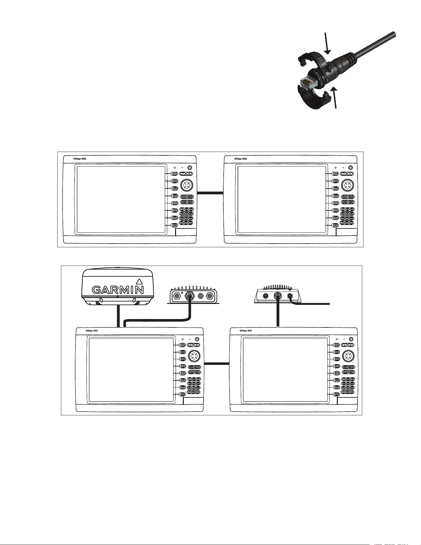
the Garmin Marine Network Cable:
• The Garmin Marine Network Cable (not included) has a locking ring that secures the cable to the
chartplotter or marine network device. Because of the size of this locking ring, it is not connected to
the network cable at the factory to make it easier to install on your boat.
• After the cable is run to the chartplotter or network device, snap the locking ring together around the
connector and insert the rubber washer as indicated on the instructions packaged with the cable.
Note: The locking ring packaged with a Garmin Marine Network Cable should not be used with
any cable packaged with the GPSMAP 6000/7000 series chartplotter.
Sample Garmin Marine Network Setups:
The following illustrations show common Garmin Marine Network setups. The illustrations only show how the devices connect to each other
using Garmin Marine Network cables. No power connections are shown in any of the diagrams. Ensure that you wire each device to power
according to the appropriate installation instructions.
Garmin GPSMAP
6000/7000 series
chartplotter
Garmin GPSMAP
6000/7000 series
chartplotter
Marine Network with two Chartplotters
Extended Marine Network with two Chartplotters
x
x
x
x
x
x
x
x
xxxxxxxxx x x x x x x x x x x
Garmin GPSMAP
6000/7000 series
chartplotter
Garmin GPSMAP
6000/7000 series
chartplotter
Garmin marine radar
GSD 22 sounder
To transducer
GDL 30A XM
®
weather receiver
GPSMAP 6000/7000 Series Installation Instructions 11
Connecting a GPSMAP 6000/7000 Series Chartplotter to an Existing Garmin Marine Network
x
x
x
x
x
x
x
x
xxxxxxxx x xx x x x x x x x x
Garmin
GPSMAP 6000/7000
series chartplotter
GSD 22 sounder unit
To transducer
Garmin marine radar
Garmin
GPSMAP 3000 series
chartplotter
GMS 10 marine network port expander
GDL 30A
XM weather receiver
NoteS:
• Every device connected to the Garmin Marine Network must be connected to the power supply for the boat. These diagrams show the
network connections; however, they do not show the power connections. Wire each device according to the appropriate installation
instructions.
• These diagrams show the Garmin Marine Network connections; however, they do not show NMeA 2000 or NMeA 0183 connections.
• When connecting a GPSMAP 6000/7000 series chartplotter to an existing Garmin Marine Network, the GMS 10 can be used but is not
necessary. The GPSMAP 6000/7000 series chartplotter has three network ports and acts as a port expander. Wire the GPS antenna and
additional NMEA devices to either an existing chartplotter or the new GPSMAP 6000/7000 Series chartplotter. The existing chartplotter and
the new GPSMAP 6000/7000 series chartplotter share NMEA 0183 data and Garmin Marine Network data.
12 GPSMAP 6000/7000 Series Installation Instructions
Wiring Additional NMEA 0183 Devices
The NMEA 0183 data cable included with the GPSMAP 6000/7000 series chartplotter supports the NMEA 0183 standard, which is used to wire
various NMEA 0183-compliant devices, such as VHF radios, NMEA instruments, autopilots, or a computer.
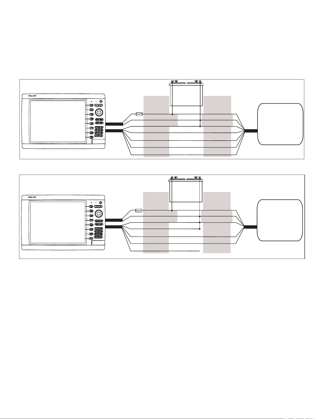
Basic NMEA 0183 Wiring
These diagrams illustrate basic NMEA 0183 wiring used to connect your GPSMAP 6000/7000 series chartplotter to NMEA 0183-compliant
devices such as an AIS or DSC device. For more-complete information on the NMEA 0183 capabilities of the GPSMAP 6000/7000 series
chartplotter, see the “Advanced NMEA 0183 Wiring” section (page 13).
Wiring to a NMEA 0183-compliant Device (AIS)
+
-
>
>
>
>
>
>
>
>
PINk RECEIvE B(-)
Garmin
GPSMAP 6000/7000 series
chartplotter
NMEA 0183-compliant
device
(AIS)
BAttERY
10–35 vdc
WIRE CoLoR WIRE
RED (PoWER)
BLACk (PWR GND)
RED (PoWER)
FuSE
7.5 A - 42 v
BLACk (DAtA GND)
WHItE
oRANGE/WHItE
GRAY
tRANSMIt A(+)
tRANSMIt B(-)
RECEIvE A(+)
BLACk (PWR GND)
BLACk (DAtA GND)
PoWER
CABLE
NMEA 0183
CABLE
Wiring to a Single-ended NMEA 0183-compliant Device
+
-
>
>
>
>
>
>
Garmin
GPSMAP 6000/7000 series
chartplotter
NMEA 0183-compliant
device
BAttERY
10–35 vdc
WIRE CoLoR WIRE
RED (PoWER)
BLACk (PWR GND)
RED (PoWER)
FuSE
7.5 A - 42 v
BLACk (DAtA GND)
WHItE
oRANGE/WHItE
GRAY
PINk
BLACk (PWR GND)
BLACk (DAtA GND)
PoWER
CABLE
NMEA 0183
CABLE
tRANSMIt
RECEIvE
uNCoNNECtED
Notes:
• If the NMEA 0183-compliant device has only one receiving wire (no A, B, +, or -), leave the pink wire unconnected.
• If the NMEA 0183-compliant device has only one transmitting wire (no A, B, +, or -), connect the orange/white wire to ground.
• Consult the installation instructions of your NMEA 0183-compliant device to identify the Transmit A(+) and B(-) wires and Receive A(+)
and B(-) wires.
• Use 28 AWG, shielded, twisted-pair wiring for extended runs of wire.
• Solder all connections and seal them with heat-shrink tubing.
GPSMAP 6000/7000 Series Installation Instructions 13
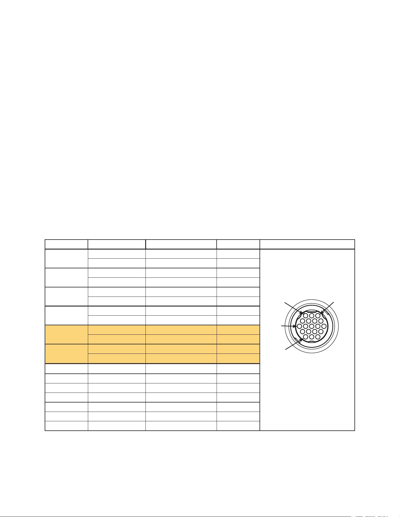
Advanced NMEA 0183 Wiring
The GPSMAP 6000/7000 series chartplotter has four ports to receive NMEA 0183 data (RX ports), and two ports to send NMEA 0183 data
(TX ports). Wire one NMEA 0183 device per RX port to send data to a 6000/7000 series chartplotter, wire up to three NMEA 0183 devices in
parallel to each TX port to receive data from a 6000/7000 series chartplotter.
Each RX and TX port has 2 wires, labeled A (+) and B (-) according to the NMEA 0183 convention. Connect the corresponding A (+) and B (-)
wires of each port to the A (+) and B (-) wires of your NMEA 0183-compliant device. Refer to the table and wiring diagrams when wiring the
6000/7000 chartplotter to NMEA 0183 devices.
Consult the installation instructions for your NMeA 0183-compliant device to identify the transfer (tX) A (+) and B (-) wires and
Receiving (RX) A (+) and B (-) wires. Use 28 AWG, shielded, twisted-pair wiring for extended runs of wire. Solder all connections and seal
them with heat-shrink tubing.
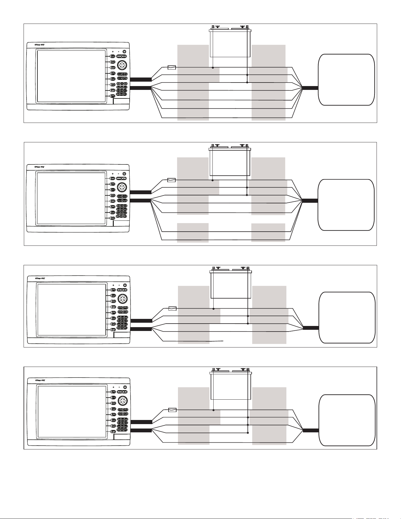
Notes:
• For two-way communication with a NMEA 0183 device, the ports on the GPSMAP 6000/7000 chartplotters are not linked. For example,
if the RX port of the NMEA-compliant device is wired to TX port 1 on the GPSMAP 6000/7000, you can wire the TX port of your NMEA
0183-compliant device to RX port 1, port 2, port 3, or port 4 on the GPSMAP 6000/7000.
• The ground wires on the NMEA 0183 data cable from the GPSMAP 6000/7000 series chartplotter and your NMEA 0183-compliant device
must both be grounded.
• Approved NMEA 0183 sentences—GPAPB, GPBOD, GPBWC, GPGGA, GPGLL, GPGSA, GPGSV, GPRMB, GPRMC, GPRTE, GPVTG,
GPWPL, GPXTE, and Garmin proprietary sentences —PGRME, PGRMM, and PGRMZ.
• The GPSMAP 6000/7000 series chartplotter also includes support for the WPL sentence, DSC, and sonar NMEA 0183 input with support for
the DPT (depth) or DBT, MTW (water temperature), and VHW (water temperature, speed, and heading) sentences.
• Select Congure > Communications on the GPSMAP 6000/7000 series chartplotter to set up NMEA 0183 communications. See the
GPSMAP 6000/7000 Series Owner’s Manual for details.
Port Wire Function Wire Color Pin Number Connector
Receiving
Port 1
RX / A (+)
White
1
RX / B (-)
orange/White
2
Receiving
Port 2
RX / A (+)
Brown
5
RX / B (-)
Brown/White
6
Receiving
Port 3
RX / A (+)
violet
9
RX / B (-)
violet/White
10
Receiving
Port 4
RX / A (+)
Black/White
11
RX / B (-)
Red/White
12
transmitting
Port 1
tX / A (+)
Gray
3
tX / B (-)
Pink
4
transmitting
Port 2
tX / A (+)
Blue
7
tX / B (-)
Blue/White
8
N/A GPS 17 IN
Green/White
13
N/A GPS 17 out
Green
14
N/A SPARE 15
N/A ALARM
Yellow
16
N/A ACCESSoRY oN
orange
17
N/A GRouND
Black
18
N/A SPARE 19
GPSMAP 6000/7000 Series NMEA 0183 Data Cable
NMEA 0183 Cable
End view
PIN 1
PIN 3
PIN 8
PIN 17
14 GPSMAP 6000/7000 Series Installation Instructions
Wiring to a Standard NMEA 0183-compliant Device with 2-way Communication
+
-
>
>
>
>
>
>
>
>
Garmin
GPSMAP 6000/7000 series
chartplotter
NMEA 0183-compliant
device
BAttERY
10–35 vdc
WIRE
SEE tABLE FoR
WIRE CoLoRS
WIRE
RED (PoWER)
BLACk (PWR GND)
RED (PoWER)
FuSE
7.5 A - 42 v
BLACk (DAtA GND)
RX / A(+)
RX / B(-)
tX / A(+)
tX / B(-)
tX / A (+)
tX / B(-)
RX / A(+)
RX / B(-)
BLACk (PWR GND)
BLACk (DAtA GND)
PoWER
CABLE
NMEA 0183
CABLE
Wiring to a Standard NMEA 0183-compliant Device for one-Way Communication
+
-
>
>
>
>
>
>
>
>
Garmin
GPSMAP 6000/7000 series
chartplotter
NMEA 0183-compliant
device
BAttERY
10–35 vdc
WIRE
SEE tABLE FoR
WIRE CoLoRS
WIRE
RED (PoWER)
BLACk (PWR GND)
RED (PoWER)
FuSE
7.5 A - 42 v
BLACk (DAtA GND)
RX / A(+)
RX / B(-)
tX / A(+)
tX / B(-)
tX / A(+)
tX / B(-)
RX / A(+)
RX / B(-)
BLACk (PWR GND)
BLACk (DAtA GND)
PoWER
CABLE
NMEA 0183
CABLE
oR oR
Wiring to Send Data to a NMEA 0183-compliant Device With a Single Wire tX Connection
+
-
>
>
>
Garmin
GPSMAP 6000/7000 series
chartplotter
NMEA 0183-compliant
device
BAttERY
10–35 vdc
WIRE
SEE tABLE FoR
WIRE CoLoRS
WIRE
RED (PoWER)
BLACk (PWR GND)
RED (PoWER)
FuSE
7.5 A - 42 v
BLACk (DAtA GND)
tX / A(+)
tX / B(-)
RX
BLACk (PWR GND)
BLACk (DAtA GND)
PoWER
CABLE
NMEA 0183
CABLE
uNCoNNECtED
Wiring to Receive Data from a NMEA 0183-compliant Device With a Single Wire RX Connection
+
-
>
>
>
Garmin
GPSMAP 6000/7000 series
unit
NMEA 0183-compliant
device
BAttERY
10–35 vdc
WIRE
SEE tABLE FoR
WIRE CoLoRS
WIRE
RED (PoWER)
BLACk (PWR GND)
RED (PoWER)
FuSE
7.5 A - 42 v
BLACk (DAtA GND)
RX / B(-)
RX / A(+)
tX
BLACk (PWR GND)
BLACk (DAtA GND)
PoWER
CABLE
NMEA 0183
CABLE
GPSMAP 6000/7000 Series Installation Instructions 15
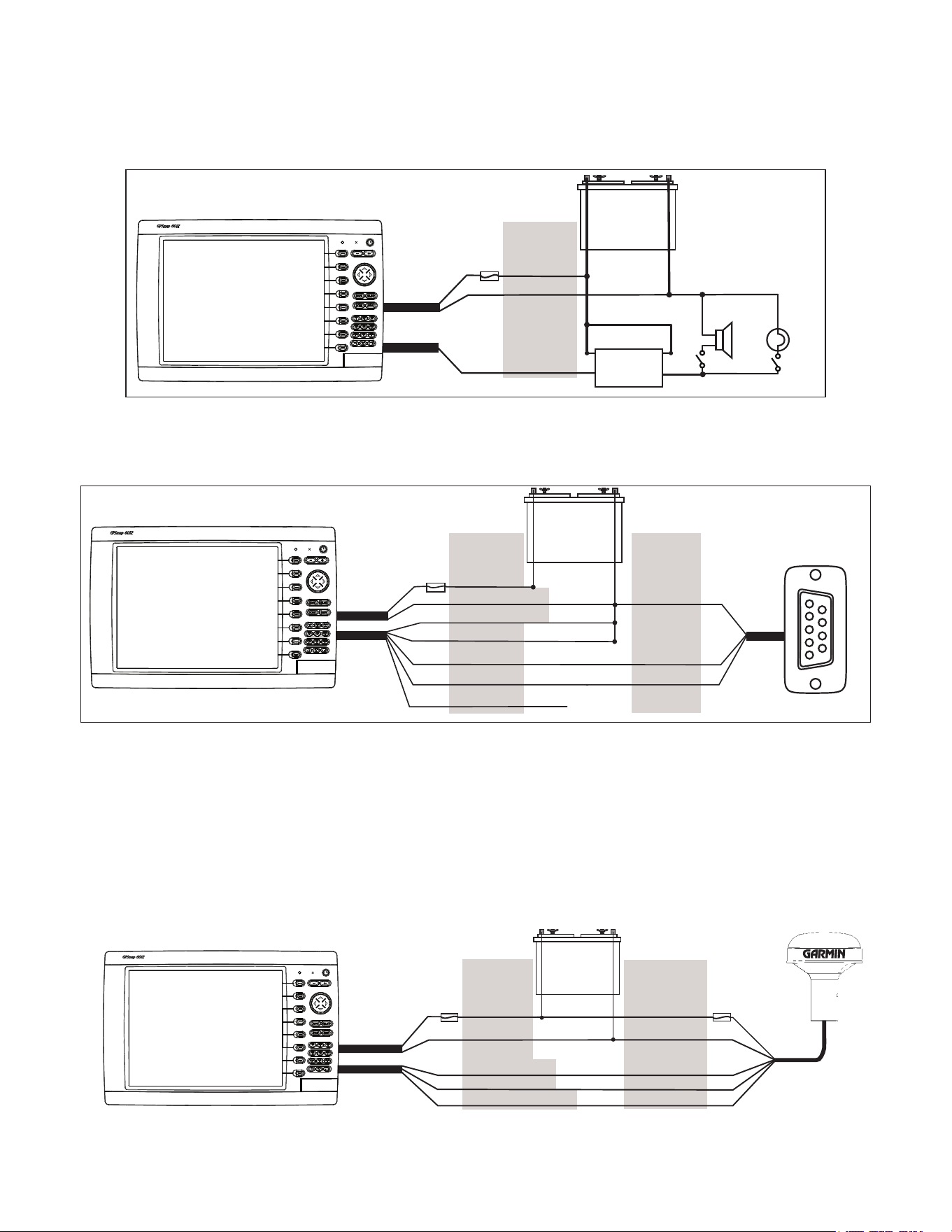
Wiring to a Lamp or to a Horn (optional)
The GPSMAP 6000/7000 series chartplotter can be used with a lamp, a horn, or both, to sound or ash an alert when the chartplotter displays a
message. The alarm does not need to be wired for the GPSMAP 6000/7000 chartplotter to function. The alarm circuit switches to a low-voltage
state when the alarm sounds. The maximum current is 100 mA, and a relay is needed to limit the current from the chartplotter to 100 mA. To
manually toggle visual and audible alerts, install single-pole, single-throw switches.
Wiring to a Lamp, a Horn, or Both
+
-
Garmin
GPSMAP 6000/7000 series
chartplotter
WIRE
CoLoR
RED (PoWER)
BLACk (GND)
YELLoW (ALARM)
BAttERY
10–35 vdc
RELAY
100 mA MAX
CoIL CuRRENt
HoRN
LAMP
FuSE
7.5 A - 42 v
PoWER
CABLE
NMEA 0183
CABLE
Wiring to a DB-9 PC Serial Connector
The GPSMAP 6000/7000 series chartplotters can be connected to a PC with a serial port by wiring the chartplotter to a DB-9 serial connector.
Wiring to a DB-9 Serial PC Connector
+
-
>
>
>
>
>
>
1
4
6
7
8
9
2
3
5
Garmin
GPSMAP 6000/7000 series
chartplotter
DB-9 serial
PC connector
BAttERY
10–35 vdc
WIRE
SEE tABLE FoR
WIRE CoLoRS
DB-9 PIN
NuMBERS
RED (PoWER)
BLACk (PWR GND)
FuSE
7.5 A - 42 v
BLACk (DAtA GND)
RX / B(-)
RX / A(+)
PIN 5: GND
PIN 3: tX
PoWER
CABLE
NMEA 0183
CABLE
uNCoNNECtED
PIN 2: RX
tX / B(-)
tX / A(+)
End view
Wiring to a GPS 17 or GPS 17 HvS Antenna
If you already have a Garmin GPS 17 or GPS 17 HVS installed on your boat, you can wire it to the GPSMAP 6000/7000 series chartplotter
instead of installing the included GPS 19x. Wire the existing GPS 17 or GPS 17 HVS antenna to the included 19-pin NMEA 0183 cable as well
as to the power supply for the boat, referring to the diagram below. Use 22 AWG shielded wiring for extended runs of wire to the NMEA 0183
cable or GPS 17 HVS cable. Solder all connections and seal them with heat-shrink tubing.
Note: If you are using more than one Garmin chartplotter over a Garmin Marine Network, do not wire more than one chartplotter to a GPS
antenna. The GPS signal is shared between multiple chartplotters connected to a Garmin Marine Network.
Wiring to a GPS 17 or GPS 17 HvS Antenna
+
-
>
>
>
>
BAttERY
10–35 vdc
WIRE
CoLoR
WIRE
CoLoR
RED (PoWER)
BLACk (GND)
oRANGE (ACC. oN)
GREEN (DAtA out)
GREEN/WHItE (DAtA IN)
RED (PoWER)
BLACk (GND)
YELLoW (oN)
BLuE (DAtA IN)
WHItE (DAtA out)
FuSE
7.5 A - 42 v
FuSE
1 A
Garmin
GPSMAP 6000/7000 series
chartplotter
GPS 17 or
GPS 17 HVS
antenna
PoWER
CABLE
NMEA 0183
CABLE
16 GPSMAP 6000/7000 Series Installation Instructions
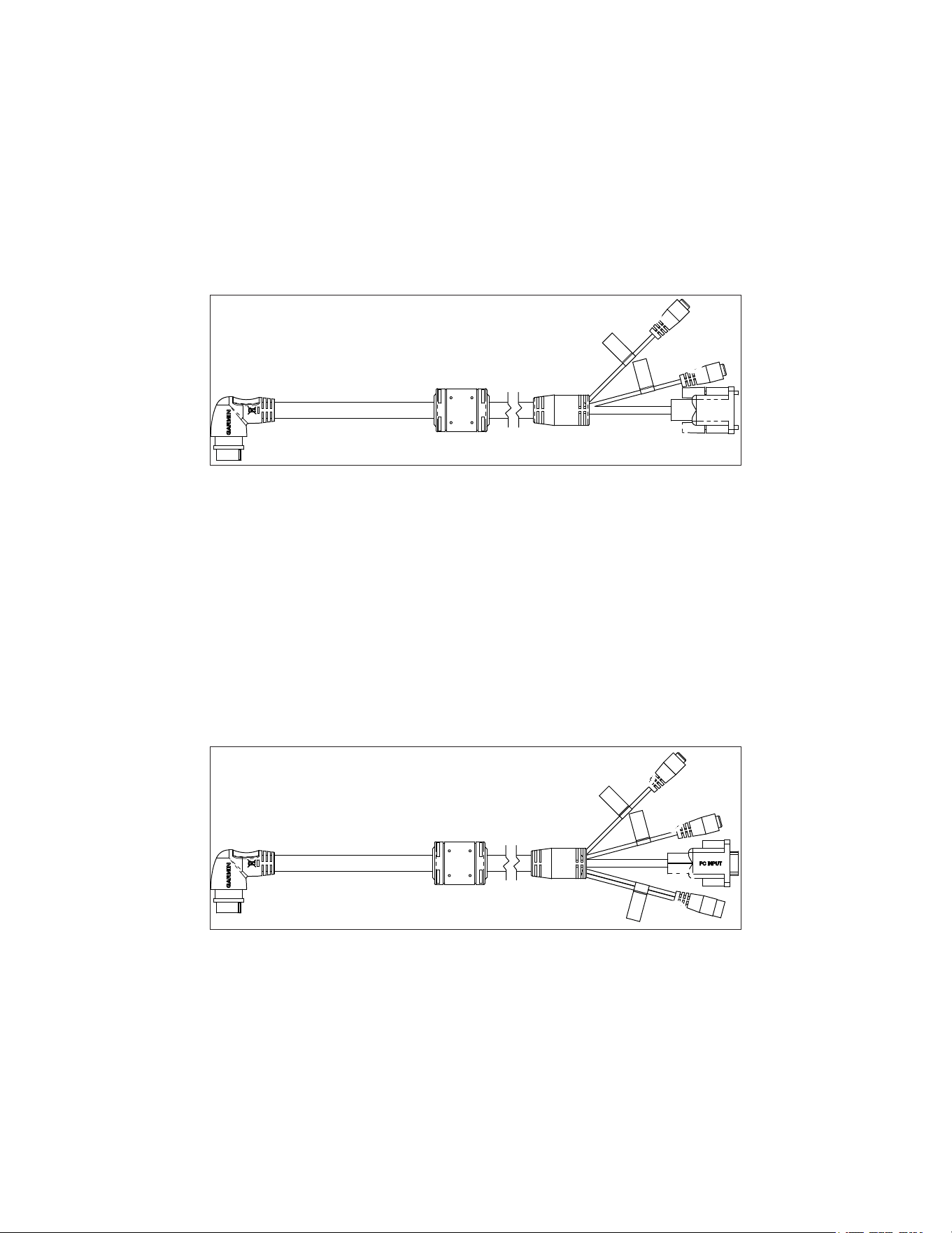
Installing video Cables
The GPSMAP 6000/7000 series chartplotters allow video input and monitor output using the included marine video 17-pin cable. The
GPSMAP 7015/7215 chartplotters have a second marine video 17-pin cable to allow for additional video sources. The GPSMAP 6000/7000
series chartplotters allow for National Television System Committee (NTSC) and Phase Alternate Line (PAL) composite video sources, and PC
monitor output (6008/6208 = VGA output, 6012/6212/7012/7212/7015/7215 = XGA output). The marine video cable inputs are only available
on the chartplotter to which they are attached and will not transmit over the Garmin Marine Network. For detailed marine video pinout
information, see the appendix (page 19).
Primary video Cable (video—Yellow Connector)
This cable is supplied with all GPSMAP 6000/7000 series chartplotters, and connects to the yellow video connector on the back of the
chartplotter. This cable allows for two separate composite video sources and it allows for video output to an external PC monitor.
Primary video Cable
DWG. NO.
SHT
320-00238-30
1
➊
➊
➋
➊
Video 1 and Video 2 inputs (RCA connectors) allow input from two separate NTSC/PAL compatible composite video devices, such as a
VCR, a DVD player, a TV, or a video camera. The chartplotter can display one video input at a time or alternate between the two. See the
GPSMAP 6000/7000 Series Owner’s Manual for details. Sound from a video source must be attached to a separate stereo/audio system.
➋
Use the PC monitor output (HD 15-pin) connector for remote viewing of the chartplotter display on a computer monitor. The remote
monitor must be capable of at least VGA resolution and have multi-sync capability. Ensure that the ground of the connected monitor is
connected to the same ground as the GPSMAP 6000/7000 series chartplotter to avoid interference.
Secondary video Cable (video 2—Purple Connector)
This cable is supplied with the GPSMAP 7015/7215 chartplotters, and it is not compatible with any other GPSMAP 6000/7000 series
chartplotter. This cable connects to the purple connector on the back of the GPSMAP 7015/7215 chartplotter, and it allows two additional
composite video sources, an S-Video source, and PC VGA input.
➌
➌
➍
➎
Secondary video Cable (GPSMAP 7015/7215 only)
➌
Video 3 and Video 4 inputs (RCA connectors) allow two NTSC/PAL compatible composite video devices, such as a VCR, a DVD player,
a TV, or a video camera. The GPSMAP 7015/7215 chartplotter can display up to four video inputs at a time, or it can cycle through all
connected video inputs. See the GPSMAP 6000/7000 Series Owner’s Manual for details. Sound from a video source must be attached to a
separate stereo/audio system.
➍
Connect a computer to the PC monitor input (HD 15-pin) connector to use the GPSMAP 7015/7215 chartplotter as a computer monitor. See
the GPSMAP 6000/7000 Series Owner’s Manual for details.
➎
S-Video input (S-Video connector) allows input of NTSC/PAL compatible S-Video devices, such as a VCR, a DVD player, a TV, or a video
camera. An S-Video connection provides a higher-quality video signal than a composite video connection.
GPSMAP 6000/7000 Series Installation Instructions 17
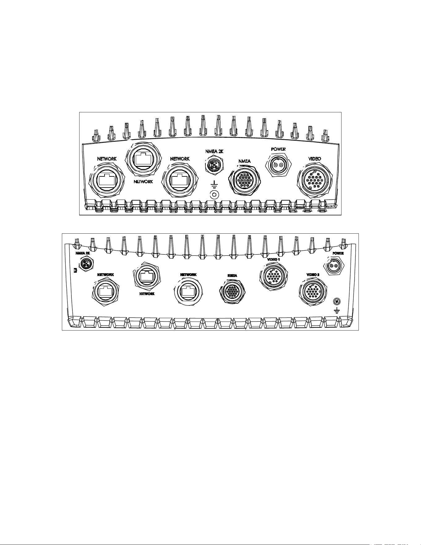
Making the Final Connections to the GPSMAP 6000/7000 Series Chartplotter
After the power cable and the GPS antenna (as well as any optional Garmin Marine Network devices, NMEA 0183 devices, NMEA 2000
connections, or video connections) are wired to the boat, connect the cables to the GPSMAP 6000/7000 series chartplotter.
Note: You must install the locking rings before connecting the cables to the chartplotter (page 6).
to connect a cable to the back of a GPSMAP 6000/7000 series chartplotter:
1. Carefullypressthecableintothecorrectportonthebackofthechartplotteruntilitisrmlyseated.Do not force the cable, because this
may damage the pins.
2. Afterthecableisseated,turnthelockingringclockwiseuntilitistight.Becarefulnottoovertightenthelockingring.
➊
➊
➊
➋
➌
➍
➎
➏
GPSMAP 6008/6208/6012/6212/7012/7212 Connectors
➊
➊
➊
➋
➌
➍
➎
➏
➐
GPSMAP 7015/7215 Connectors
➊
Garmin Marine Network connectors (×3) (Black)
➋
NMEA 2000 connector (Black)
➌
NMEA 0183 connector (Blue)
➍
Power connector (Red)
➎
Video connector (Yellow)
➏
Grounding lug (unused in a typical installation)
➐
Video 2 connector (GPSMAP 7015/7215 only) (Purple)
updating the Chartplotter Software
The GPSMAP 6000/7000 series chartplotter may contain a software update SD card. If so, follow the instructions provided with the card.
If a software update SD card is not included, visit www.garmin.com to make sure your chartplotter software is up-to-date. To identify the
version of software on your chartplotter, select or touch Congure > System > System Information.
18 GPSMAP 6000/7000 Series Installation Instructions
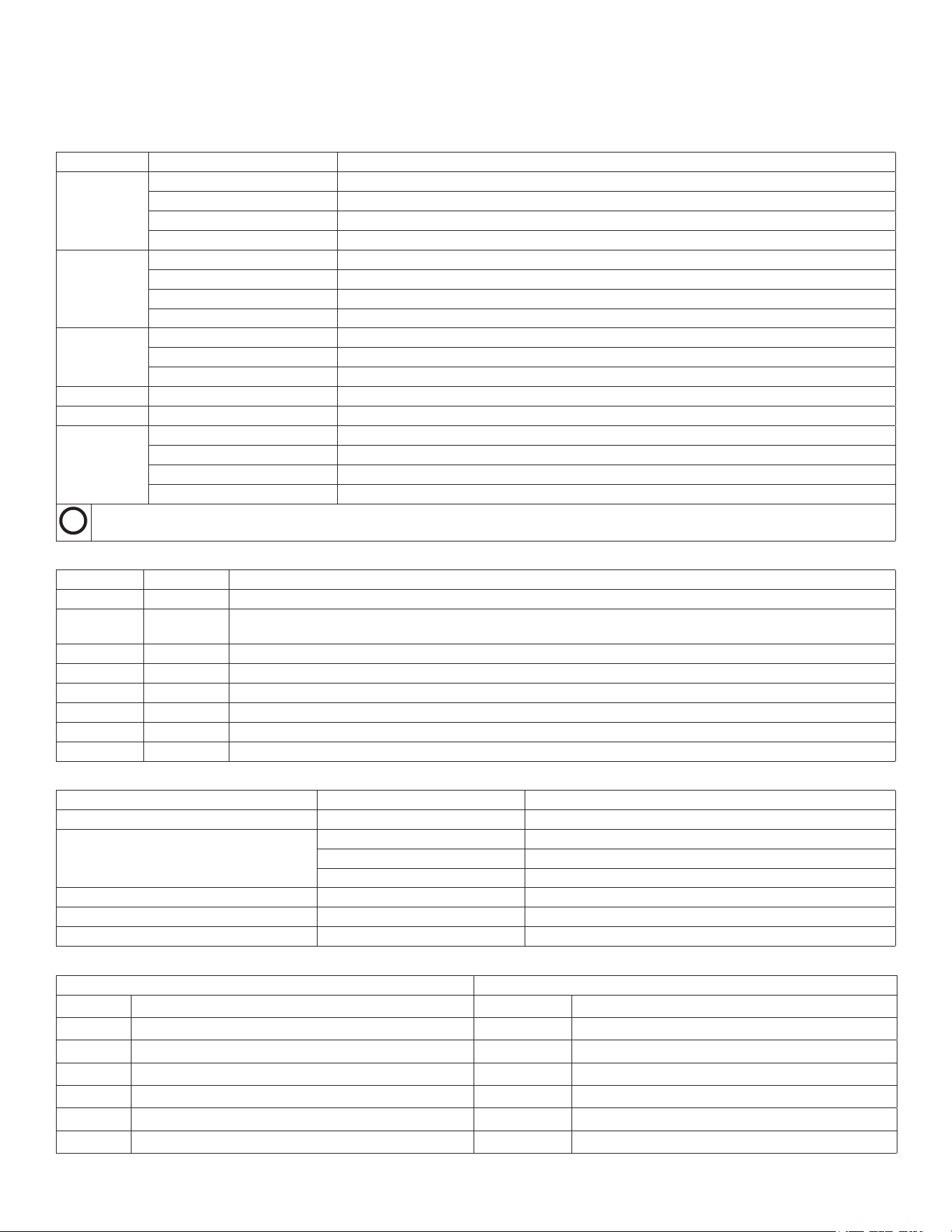
Appendix
Specications
Physical Specications
Specication Devices Measurement
Size GPSMAP6008,6208 W×H×D:11
1
/
2
×7
3
/
8
×5
7
/
8
in.(291.5×187.8×148.5mm)
GPSMAP6012,6212 W×H×D:15
1
/
32
×9
57
/
64
×5
27
/
32
in.(381.7×251.2×148.7mm)
GPSMAP7012,7212 W×H×D:13
9
/
32
×9
7
/
8
×5
27
/
32
in.(336.8×251.5×147.8mm)
GPSMAP7015,7215 W×H×D:15
17
/
32
×11
27
/
32
×5
7
/
8
in.(394.9×300.7×148.5mm)
Weight GPSMAP6008,6208 11lb.,5oz.(5.12kg)
GPSMAP6012,6212 15lb.,15oz.(7.23kg)
GPSMAP7012,7212 15lb.,5oz.(6.94kg)
GPSMAP7015,7215 17lb.,6oz.(7.87kg)
Display GPSMAP6008,6208 W×H:6¾×5
1
/
8
in.(174×131.3mm)
GPSMAP6012,6212,7012,7212 W×H:9
11
/
16
×7
1
/
4
in.(245.8×184.3mm)
GPSMAP7015,7215 W×H:12×9in.(304.1×228.1mm)
Case Allmodels Fullygasketed,high-impactplasticandaluminumalloy,waterprooftoIEC60529IPX-7
Temp.Range Allmodels From5°Fto131°F(from-15°Cto55°C)
CompassSafe
Distance
GPSMAP6008,6208 15in.(38.1cm)
GPSMAP6012,6212 16in.(40.6cm)
GPSMAP7012,7212 25in.(63.5cm)
GPSMAP7015,7215 17in.(43.2cm)
Hg
-Lampsinsidethisproductcontainmercuryandmustberecycledordisposedofaccordingtolocal,state,orfederallaws.Forinformation,goto:
www.garmin.com/aboutGarmin/environment/disposal.jsp.
GPS Performance
Specication Parameter Measurement
Receiver GPS19x:HighSensitivityDifferential-ready12parallelchannelWAAS-capablereceiver
Acquisition
Time
Warm Approximately38sec.(Thedeviceisatornearthelastlocationatwhichyourecentlyacquiredsatellites)
Cold Approximately45sec.(Thedevicehasmovedmorethanabout500mi.(800km)sinceitwasturnedoff.)
Reacquisition <2seconds
UpdateRate 1/sec.,continuous
Accuracy GPS <33ft.(10m)95%typical
DGPS 10-16ft.(3-5m)95%typical(WAAS/EGNOSaccuracy)
Velocity 0.05m/sec.steadystate
Power
Specication Devices Measurement
Source Allmodels 10-35Vdc
Usage GPSMAP6008,6208 35Wmax.at10Vdc
GPSMAP6012,6212,7012,7212 45Wmax.at10Vdc
GPSMAP7015,7215 65Wmax.at10Vdc
Fuse Allmodels 7.5A,42Vfast-acting
NMEA2000LoadEquivalencyNumber(LEN) Allmodels 2
NMEA2000Draw Allmodels 75mAmaximum
NMEA 2000 PGN Information
Receive transmit
059392 ISOAcknowledgment 059392
ISOAcknowledgment
059904 ISORequest 059904
ISORequest
060928 ISOAddressClaim 060928
ISOAddressClaim
126208 NMEA-Command/Request/AcknowledgeGroupFunction 126208
NMEA-Command/Request/AcknowledgeGroupFunction
126464 Transmit/ReceivePGNListGroupFunction 126464
Transmit/ReceivePGNListGroupFunction
126992 SystemTime 126996
ProductInformation
126996 ProductInformation 127250
VesselHeading
GPSMAP 6000/7000 Series Installation Instructions 19
Receive transmit
127250 VesselHeading 127258
MagneticVariance
127489 EngineParameters-Dynamic 128259
Speed-WaterReferenced
127488 EngineParameters-RapidUpdate 128267
WaterDepth
127493 TransmissionParameters,Dynamic 129025
Position-RapidUpdate
127505 FluidLevel 129026
COG&SOG-RapidUpdate
128259 Speed-WaterReferenced 129029
GNSSPositionData
128267 WaterDepth 129283
CrossTrackError
129025 Position-RapidUpdate 129284
NavigationData
129026 COG&SOG-RapidUpdate 129285
NavigationRoute/WaypointInfo
129029 GNSSPositionData 129540
GNSSSatsinView
129038 AISClassAPositionReport 130306
WindData
129039 AISClassBPositionReport 130312
Temperature
129040 AISClassBExtendedpositionreport
129539 GNSSDOPs
129540 GNSSSatsinView
129794 AISClassAStaticandVoyageRelatedData
GPSMAP6000/7000serieschartplottersare
NMEA2000certied.
129808 DSCCallInformation
129809 AISClassB"CS"StaticDataReport,PartA
129810 AISClassB"CS"StaticDataReport,PartB
130306 WindData
130310 EnvironmentalParameters
130311 EnvironmentalParameters
130312 Temperature
130313 Humidity
130314 ActualPressure
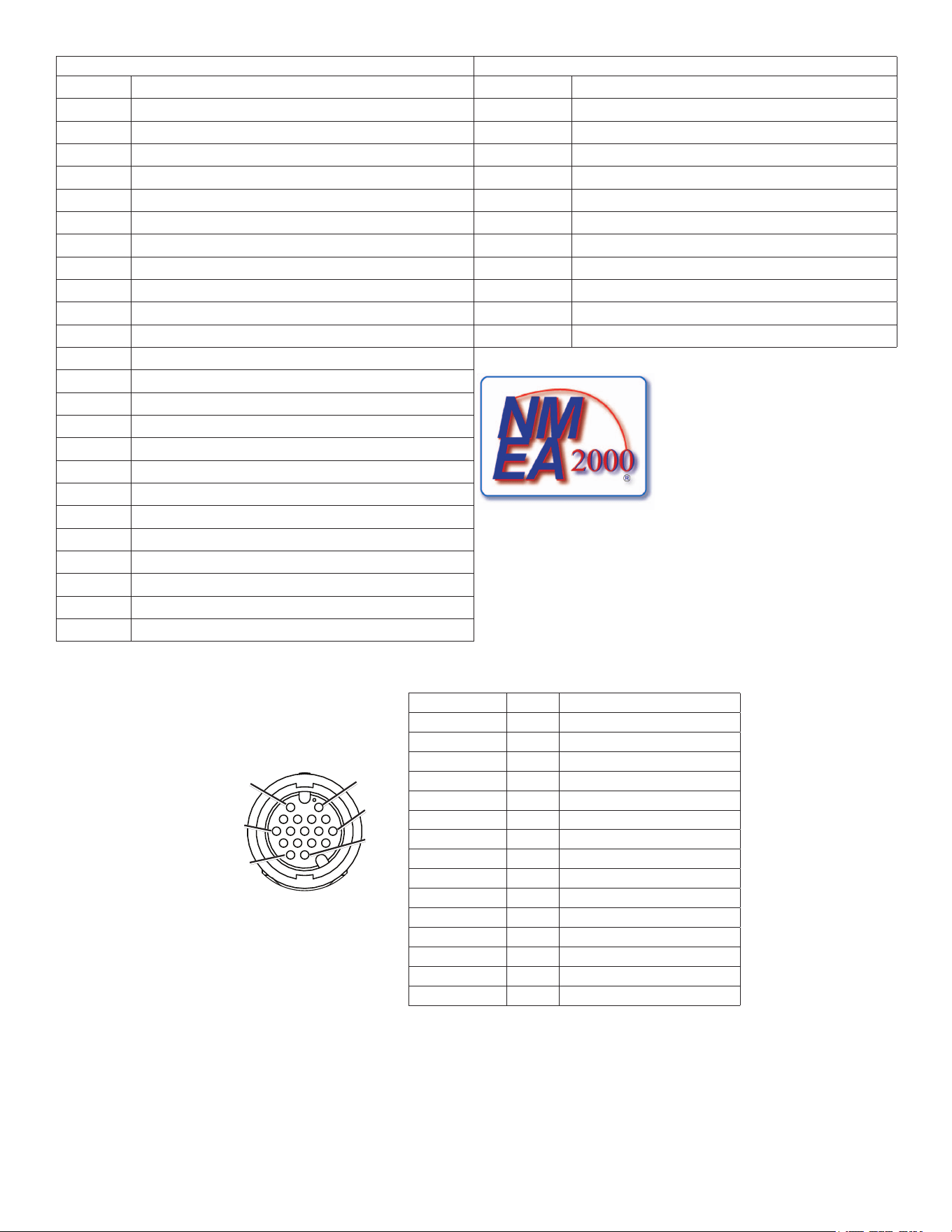
Marine video Cable Pin Assignments
Connector Pin Function
RCA1center 2 Video1in
RCA1outer 6 Video1ground
RCA2center 11 Video2in
RCA2outer 15 Video2ground
HD-15pin1 1 VGA,analog—red
HD-15pin2 4 VGA,analog—green
HD-15pin3 3 VGA,analog—blue
HD-15pin5 13 VGA,analog—ground
HD-15pin6 8 VGA,analog—red,ground
HD-15pin7 8 VGA,analog—green,ground
HD-15pin8 8 VGA,analog—blue,ground
HD-15pin10 13 VGA,syncground
HD-15pin13 7 VGA,horizontalsync
HD-15pin14 12 VGA,verticalsync
HD-15shell 9 VGA,overallshield
Primary Marine
video Cable
Pin 1Pin 2
Pin 7
Pin 16
Pin 11
Pin 17
Primary Marine video Cable Pin Assignments
© 2012 Garmin Ltd. or its subsidiaries
All rights reserved. Except as expressly provided herein, no part of this manual may be reproduced, copied, transmitted, disseminated, downloaded or stored in any storage
medium, for any purpose without the express prior written consent of Garmin. Garmin hereby grants permission to download a single copy of this manual onto a hard drive or
other electronic storage medium to be viewed and to print one copy of this manual or of any revision hereto, provided that such electronic or printed copy of this manual must
contain the complete text of this copyright notice and provided further that any unauthorized commercial distribution of this manual or any revision hereto is strictly prohibited.
Information in this document is subject to change without notice. Garmin reserves the right to change or improve its products and to make changes in the content without
obligation to notify any person or organization of such changes or improvements. Visit the Garmin Web site (www.garmin.com) for current updates and supplemental
information concerning the use and operation of this and other Garmin products.
Garmin
®
, the Garmin logo, GPSMAP
®
, BlueChart
®
, and g2 Vision
®
are trademarks of Garmin Ltd. or its subsidiaries, registered in the USA and other countries. These
trademarks may not be used without the express permission of Garmin. NMEA 2000
®
is a registered trademark of the National Marine Electronics Association.
XM
®
and XM WX Satellite Weather
®
are registered trademarks of XM Satellite Radio Inc.
For the latest free software updates (excluding map data) throughout the life of your
Garmin products, visit the Garmin Web site at www.garmin.com.
©2012GarminLtd.oritssubsidiaries
GarminInternational,Inc.
1200East151
st
Street,Olathe,Kansas66062,USA
Garmin(Europe)Ltd.
LibertyHouse,HounsdownBusinessPark,Southampton,Hampshire,SO409LRUK
GarminCorporation
No.68,Zhangshu2
nd
Road,XizhiDist.,NewTaipeiCity,221,Taiwan(R.O.C.)
April2012 PartNumber190-01495-02Rev.B PrintedinTaiwan
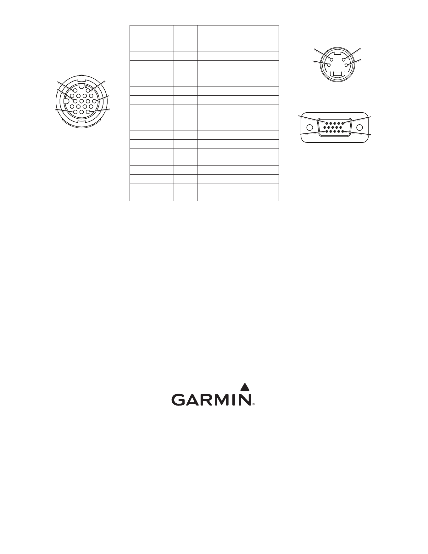
Secondary Marine
video Cable
(7015/7215 only)
Pin 1Pin 2
Pin 7
Pin 16
Pin 11
Pin 17
Connector Pin Function
RCA1center 2 Video3in
RCA1outer 6 Video3ground
RCA2center 11 Video4in
RCA2outer 10 Video4ground
HD-15pin1 1 VGA,analog—red
HD-15pin2 4 VGA,analog—green
HD-15pin3 3 VGA,analog—blue
HD-15pin5 13 VGA,analog—ground
HD-15pin6 8 VGA,analog—red,ground
HD-15pin7 8 VGA,analog—green,ground
HD-15pin8 8 VGA,analog—blue,ground
HD-15pin10 13 VGA,syncground
HD-15pin13 7 VGA,horizontalsync
HD-15pin14 12 VGA,verticalsync
HD-15shell 9 VGA,overallshield
S-Videopin3 16 S-Videoin,luminance
S-Videopin1 14 S-Videoin,luminance,ground
S-Videopin4 17 S-Videoin,chrominance
S-Videopin2 15 S-Videoin,chrominance,ground
S-video In
Pin 3
Pin 4
Pin 1
Pin 2
vGA In
Pin 5
Pin 1
Pin 15Pin 11
Secondary Marine video Cable Pin Assignments (GPSMAP 7015/7215 only)