REV A DATE: 5/22/24
21-33897 OASIS REF SELF-SERVICE MI-EN-A-052224
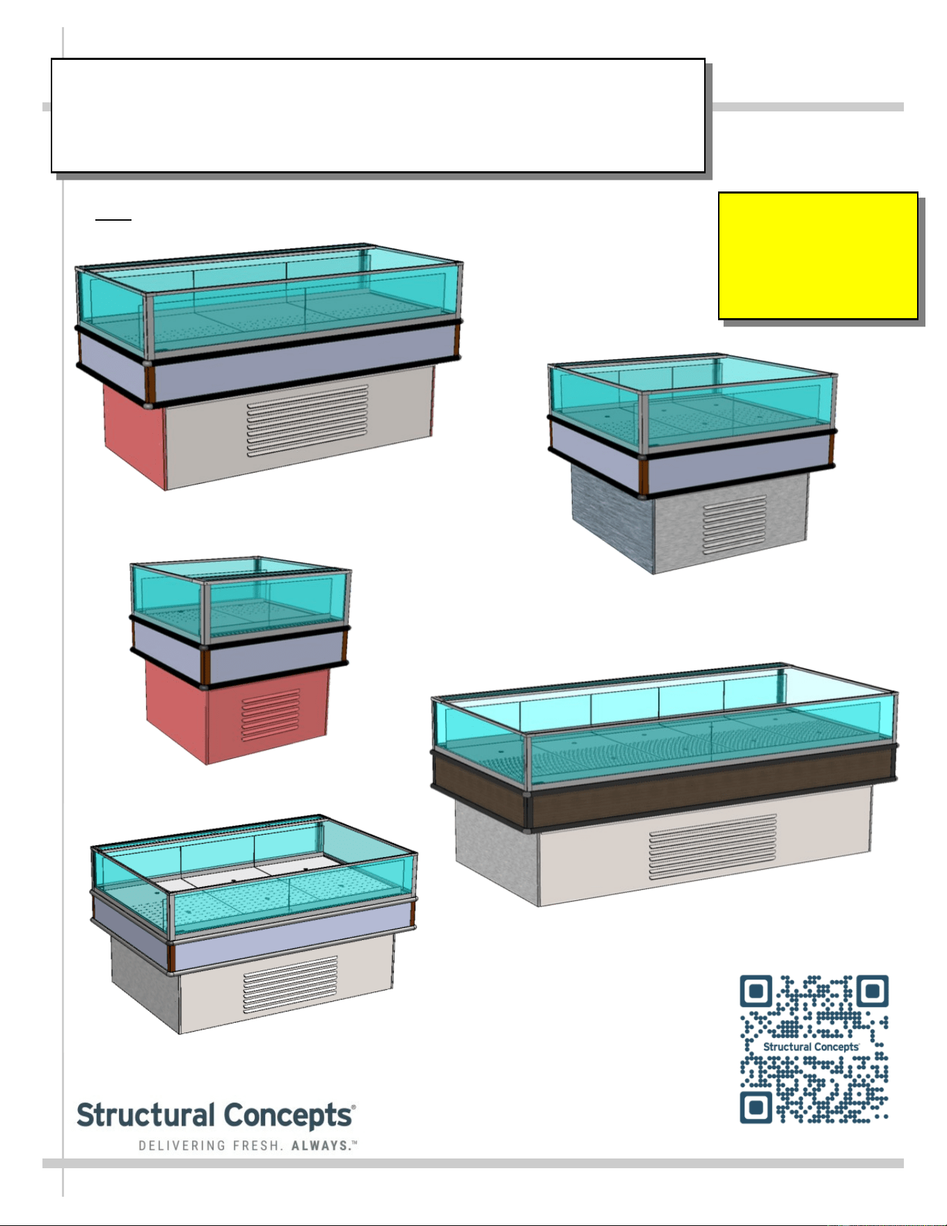
SELF-SERVICE MULTI-PURPOSE REFRIGERATED ISLAND DISPLAY CASES
> Note: See Next Page For List of Models To Which This Manual Applies
Important!
See Page 13
For Product And
Signage Placement
Guidelines!
MI48R / Removable Exterior Panels /
No Acrylic Airflow Risers or Dividers
MI36R
MI44R
MI33R
USER
MANUAL
PN 21-33897
OASIS
READ AND SAVE THESE INSTRUCTIONS
®
Structural Concepts Corp. ∙ 888 E. Porter Rd ∙ Muskegon, MI 49441 Phone: 231.798.8888 Fax: 231.798.4960 ∙ www.structuralconcepts.com
MI46R
2
TABLE OF CONTENTS
OVERVIEW / TYPE / COMPLIANCE / WARNINGS / PRECAUTIONS / WIRING / PLUGS .............…..
CASE REMOVAL FROM SKID (LOCKING/UNLOCKING CASTERS) ……………………..………….…..
EXTERIOR PANEL ATTACHMENT (AFTER REMOVAL FROM SKID AND PROPERLY
POSITIONED) …………………………………………………………………………………….……..
POSITIONING-LEVELING UNIT / START-UP / TEMPERATURE CONTROL / 41 °F & 38 °F
SWITCH ………………………..…………………………………………………………………….…..
ADJUSTABLE ACRYLIC DIVIDERS / FIXED ACRYLIC DIVIDERS / HORIZONTAL GLASS
FIXTURES …………………………………………………….………………………………………....
EVAPORATOR SECTION ACCESS: BAFFLED DECK PAN ASSEMBLIES / THERMOMETER .…......
EVAPORATOR SECTION ACCESS, CONT’D: LOWER DECK PAN REMOVAL / EVAPORATOR
SECTION COMPONENTS ………………………………………………………………………….….
LOAD LIMIT (LOAD LINE) GUIDELINES / CASE FRONT & REAR DESIGNATIONS /
THERMOMETER ………………………………………………………………………………….…….
PRODUCT AND SIGNAGE PLACEMENT GUIDELINES …………………………………………………..
REFRIGERATION FUNDAMENTALS - REFRIGERATION. PACKAGE / TEMPERATURE
CONTROLLER / EVAPORATOR PAN ACCESS ……...……………………………….…………...
CONDENSER PACKAGE EXPLODED PICTORIAL - WITH SMALL HOT GAS LOOP
CONDENSATE UNIT …..……………………………………………………………………………...
CONDENSER PACKAGE EXPLODED PICTORIAL - WITH LARGE HOT GAS LOOP
CONDENSATE UNIT ...………………………………………………………………………………...
CLEANING SCHEDULE …………….………………….……………………………….…………………….
PREVENTIVE MAINTENANCE (PERFORMED BY TRAINED SERVICE PROVIDER) ………………...
TROUBLESHOOTING (GENERAL) ..………………….………………………………….……….………….
SERIAL LABEL LOCATION & INFORMATION LISTED / TECH INFO & SERVICE …………..………..
PROGRAMMABLE CONTROLLER INFORMATION…... …….…………………………………………….
TECHNICAL SERVICE CONTACT INFORMATION / WARRANTY INFORMATION ...……………..…
3-6
7
8
9
10
11
12
13
14
15
16
17
18
19-24
25-26
27
28
29
This Operating Manual Applies To The Following Models*:
MI3R.5429, MI3R.6212B, MI36R, MI5R, MI6R, MI6R.6212C, MI6R.6620, MI6R.7065, MI8R,
MI8R.6212A, MI32R, MI33R, MI36R, MI44R, MI44R.7523, MI45R, MI46R, MI48R & MI48R.7788
*Note: Manual May Also Apply To Additional Models Not Listed Herein.
3
OVERVIEW / TYPE / COMPLIANCE / WARNINGS / PRECAUTIONS / WIRING / PLUGS - PAGE 1 of 4
OVERVIEW
• These Structural Concepts merchandisers are designed
to merchandise packaged products at 41°F (5°C) or less
product temperatures.
• Refrigerated Display cases are classified by “Test Room
Climate Class.” Test Room Climate Class 8 is to be
operated in a environment of 24°C (75.2°F) 55% R.H.
• Cases should be installed and operated according to
this operating manual’s instructions to ensure proper
performance. Improper use will void warranty.
NSF/ANSI TYPE II ENVIRONMENTAL CONDITIONS
• This unit is designed for the display of products in
ambient indoor store conditions where temperature and
humidity are maintained within a specific range.
• This NSF/ANSI Type II display refrigerator is intended to
be used where environmental conditions are controlled
and maintained so that ambient temperature does not
exceed 80 °F (27 °C) and 55% relative humidity.
• Due to atmospheric pressure considerations, it is not
recommended that these box door cases operate
beyond 6,562 FASL (feet above sea level) / 2,000 MASL
(meters above sea level). If your facility exceeds this
thresholds, please contact Structural Concepts Corp.
COMPLIANCE
• Performance issues when in violation of applicable NEC,
federal, state and local electrical and plumbing codes
are not covered by warranty. See below.
REFRIGERANT DISCLOSURE STATEMENT
• This equipment is prohibited from use in California with
any refrigerants on the “List of Prohibited Substances”
for that specific end-use, in accordance with California
Code of Regulations, title 17, section 95374.
• This disclosure statement has been reviewed and
approved by Structural Concepts and Structural
Concepts attests, under penalty of perjury, that these
statements are true and accurate.
>> See next page for continuation.
WARNING
Hazardous moving parts. Do not operate unit with covers removed.
Fan blades may be exposed when deck panel is removed.
Disconnect power before removing deck panel.
WARNING
Risk of electric shock. Disconnect power before servicing unit.
CAUTION! More than one source of electrical supply is
employed with units that have separate circuits.
Disconnect ALL ELECTRICAL SOURCES before servicing.
WARNING
Condensate Pan is Hot!
Disconnect and allow to cool before cleaning or removing from case.
WARNING
ELECTRICAL
HAZARD
WARNING
HOT
SURFACE
COMPLIANCE
• These cases MUST be installed in compliance with all applicable NEC,
federal, state and local electrical and plumbing codes.
• These cases must ALSO be installed in accordance with the Safety
Standard for Refrigeration Systems, ANSI/ASHRAE 15.
• ONLY factory authorized service personnel are to service these box cases.
ATTENTION
CONTRACTORS
WARNING
KEEP HANDS
CLEAR
WARNING
This product can expose you to chemicals, including
Urethane (Ethyl Carbamate), which are known to the state of
California to cause cancer and birth defects or other reproductive harm.
For more information go to P65Warnings.ca.gov.
4
OVERVIEW / TYPE / COMPLIANCE / WARNINGS / PRECAUTIONS / WIRING / PLUGS - PAGE 2 of 4
OVERVIEW, CONT’D
• This sheet details dangers due to flammable refrigerant. It
addresses operational area required, case placement
guidelines, child-proofing the unit and refrigerant
recycling and/or disposal, etc.
• Appliance is to be installed in accordance with the Safety
Standard for Refrigeration Systems., ANSI/ASHRAE15.
DANGER
• Please read section shown below for specifics on risk of
fire explosion, service guidelines, LFL, etc.
CAUTION
• This sheet also details the area required for operation,
areas to avoid placing case, guidelines for children (and
others with limited capabilities) while near box door
cases.
• This sheet also provides information on refrigeration
recovery, recycling and disposal.
>> See next page for continuation.
DANGER
• Refrigeration unit contains gas under high pressure. Do not tamper with or
puncture the system. Contact qualified service personnel before disposal.
• Risk of fire or explosion. Flammable refrigerant is used in this case.
• Consult repair manual/owner’s guide before servicing this product.
• Do not store explosive substances (such as aerosol cans with a flammable
propellant) in this case.
• Do not use an electrical appliance INSIDE the food storage compartments
unless its type is recommended by manufacturer.
• To minimize risk of ignition due to incorrect parts or improper service, this case
is ONLY to be serviced by factory authorized service personnel.
• Flammable refrigerant type specified on case nameplate is on serial label.
• Contains a charge of 150g of R290 refrigerant with a lower flammability limit
(LFL) of .038kg/m³
CAUTION
• This unit is not intended for use by persons (including children) with reduced
physical, sensory or mental capabilities, or lack of experience and knowledge,
unless they have been given supervision or instruction concerning use of the
unit by a person responsible for their safety.
• Children should be supervised to ensure that they do not ‘play with’ the unit.
CAUTION
CAUTION: REFRIGERANT RECOVERY/RECYCLING/DISPOSAL
• When recycling or discarding case, refrigerants MUST BE handled according to
local, state and federal codes, requirements and regulations.
• If disposing of a refrigerated case that uses ozone depleting chemicals in its re-
frigeration system, make sure the refrigerant is removed by a qualified
service technician and properly disposed of.
• If you intentionally release refrigerant into the atmosphere, you may be
subject to fines or other penalties (under regulations mandated by
environmental regulators and/or legislative edict).
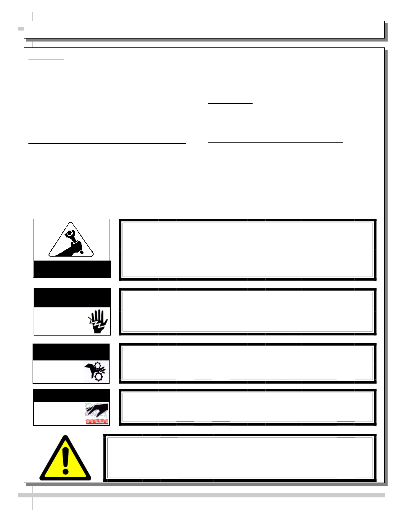
≥7.1m²
CAUTION
Minimum room floor area required for operation of
these cases is ≥7.1m².
CAUTION
• These cases are NOT to be installed in lobbies or locations of egress, such as
hallways, public corridors.
• If case is placed in an enclosure or surrounding structure, keep all of the case’s
ventilation openings clear of obstructions.
5
OVERVIEW / TYPE / COMPLIANCE / WARNINGS / PRECAUTIONS / WIRING / PLUGS - PAGE 3 of 4
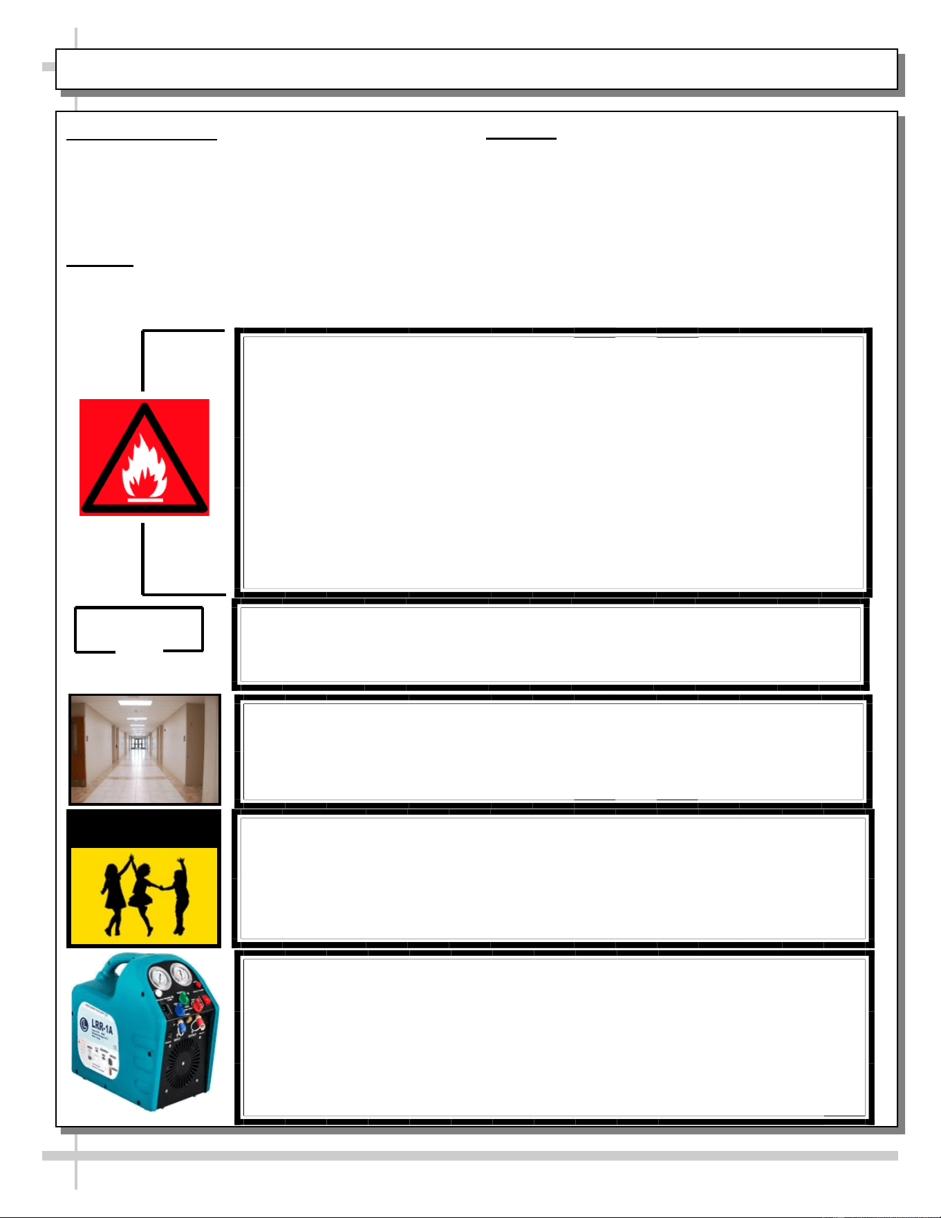
CAUTION! GFCI BREAKER USE REQUIREMENT
If N.E.C. (National Electric Code) or local code requires GFCI (Ground
Fault Circuit Interrupter), use a GFCI breaker in lieu of a GFCI receptacle.
CAUTION! LAMP REPLACEMENT GUIDELINES
LED lamps reflect specific size, shape and design.
Any replacements must meet factory specifications, resist breakage
and reflect similar appearance as lamps from factory.
CAUTION
CAUTION! POWER CORD AND PLUG MAINTENANCE
Risk of electric shock. If cord or plug becomes damaged,
replace only with cord and plug of same type.
CAUTION! CHECK CONDENSATE PAN, POSITION & CONNECTIONS!
Water on flooring can cause extensive damage!
• Before powering up case, check that condensate pan is positioned directly
under case’s condensate drain.
• Also, check that there are NO LOOSE CONNECTIONS, including overflow
condensate pan and its power cord plug (if part of the condensate package).
CAUTION! DO NOT RELY ON THERMOMETERS OR
THERMOSTATS FOR PRODUCT (FOOD) TEMPERATURES.
• Thermometers & thermostats reflect air temperatures ONLY.
• For ACTUAL product (food) temperatures, use a calibrated food
probe thermometers ONLY.
• For accurate readings, DO NOT use infrared food thermometers.
WIRING DIAGRAM FORMAT & LOCATION
• Each case has its own wiring diagram folded and in its own packet.
• Wiring diagram placement may vary; it may be placed near ballast
box, field wiring box, raceway cover, or other related location.
• Adjoined cases must be connected to each other so that vending
controls system properly communicates with additional case.
PRECAUTIONS
• This sheet contains important precautions to prevent
damage to unit or merchandise. Please read carefully!
• See previous page for specifics on OVERVIEW,
TYPE, COMPLIANCE and WARNINGS.
• Do no use mechanical devices or other means to
accelerate the defrosting process, other than those
recommended by the manufacturer.
• Only factory OEM replacement parts may be used on
appliances using flammable refrigerants.
• Risk of electric shock. If the SUPPLY CORD is
damaged, it must be replaced by the manufacturer, its
service agent or similarly qualified persons with factory
OEM replacement parts only.
WIRING DIAGRAM
• Each case has its own wiring diagram folded and in its
own packet.
• Location: Diagram may be near ballast box, field wiring
box, raceway cover, or other related location.
6
OVERVIEW / TYPE / COMPLIANCE / WARNINGS / PRECAUTIONS / WIRING / PLUGS - PAGE 4 of 4
WARNING
Do not use means to accelerate the defrosting process or to clean, other than those recommend-
ed by the manufacturer.
The appliance shall be stored in a room without continuously operating ignition sources (for ex-
ample: open flames, an operating gas appliance or an operating electric heater.)
Do not pierce or burn.
Be aware that refrigerants may not contain an odor.
7 7
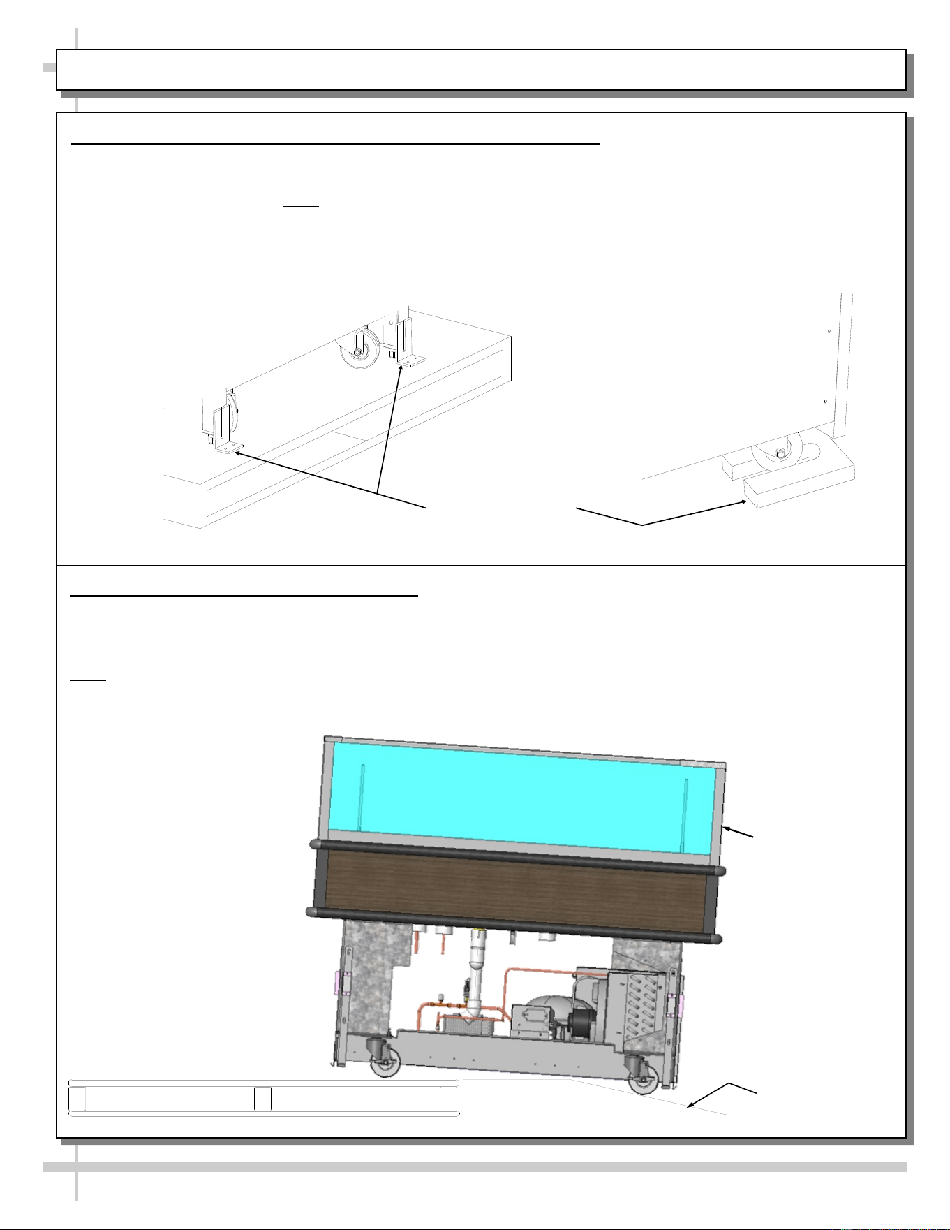
CASE REMOVAL FROM SKID (LOCKING/UNLOCKING CASTERS)
Various Types Of
Case Shipping
Brackets
1. Removing Case Shipping Brackets That Are Attached To Skid
• Remove screws holding shipping brackets to skid.
• Remove shipping brackets from skid.
• See illustrations below. Note: Shipping Brackets will vary in size, shape, material and location depending
upon case type and model.
2. Remove Case (With Casters) From Skid
A. Place ramp up against skid (to allow case to smoothly slide off from skid).
B. Maintain support of case at all times or center of gravity may cause case to fall.
C. Unlock Casters. Slide unit to rear of skid. Slide down ramp and off from skid.
Note: See next page for panel attachment instructions.
Support case
while sliding
down ramp.
Ramp
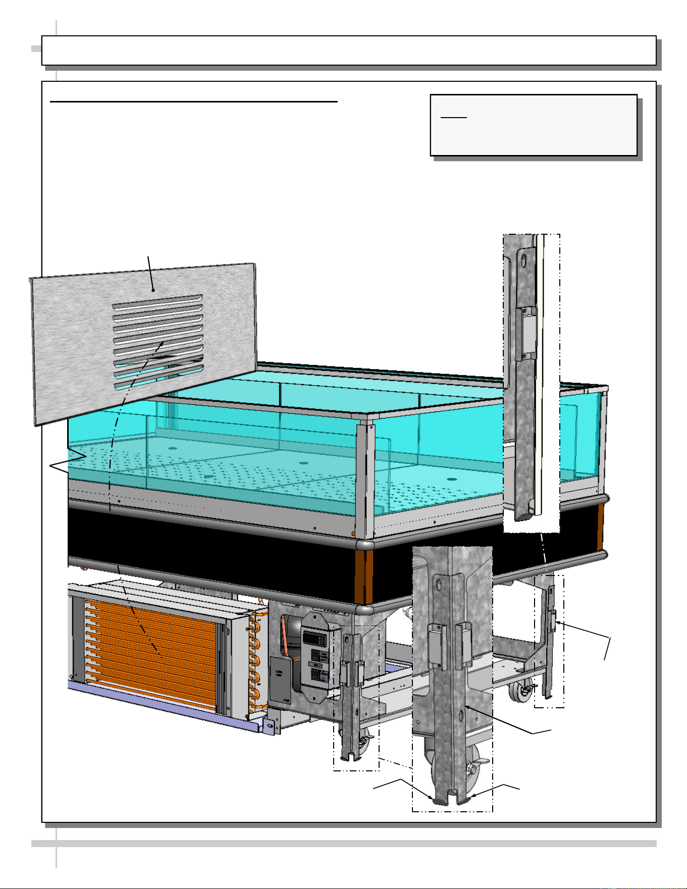
EXTERIOR PANEL ATTACHMENT (AFTER REMOVAL FROM SKID AND PROPERLY POSITIONED)
8
Exterior Panel Attachment (Both Grille and Solid)
• Attach to case after case has been removed and properly
positioned/located in store.
• All four (4) exterior panels may be removed without tools.
• Lift exterior panel up and off tabs.
• Separate lower panel from magnets
• See illustrations below.
Note: Illustrations Shown May Not
Reflect Every Feature Or Option
Of Your Particular Case.
Hook (Typ.)
Magnet (Typ.)
Front Base Panel
Bracket (Typ.)
Lower Front Panel
Hook (Typ.)
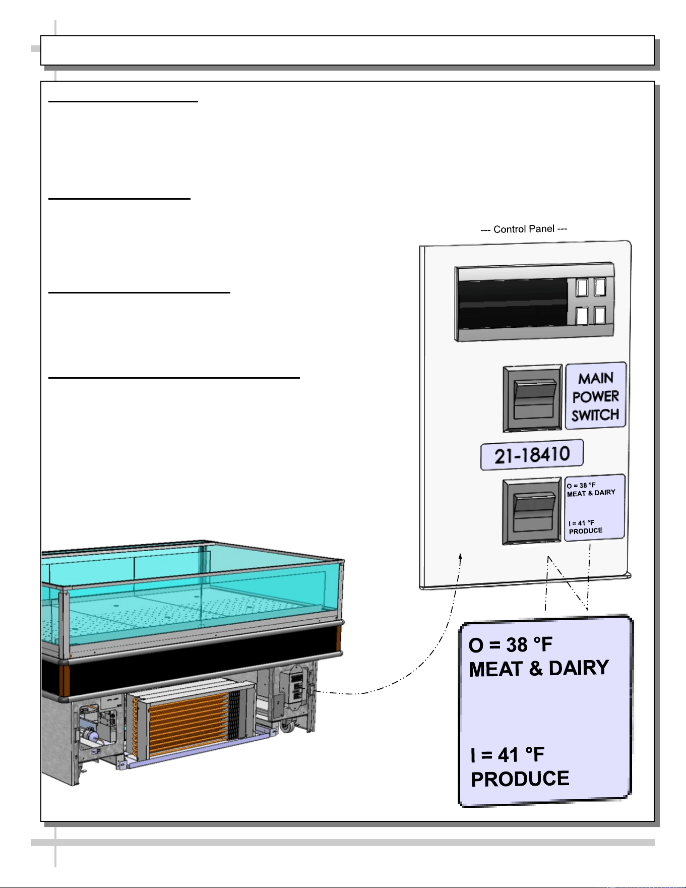
POSITIONING-LEVELING UNIT / START-UP / TEMPERATURE CONTROL / 41 °F & 38 °F SWITCH
9
1. Position and Level Unit
• Position unit. Remove either controls side or
opposite side grille to access levelers (see
below). Grilles may be simply lifted up and off.
• Level unit by either hand-cranking or using
adjustable wrench (see below). Return grilles.
2. Display Case Start-Up
• Lift up controls cover on control side of unit (see
illustrations below).
• Turn on main power switch.
• Main power switch will start evaporator coil fans,
and the compressor motor.
3. Temperature Control Access
• Lift up controls cover on control side of unit.
• See the temperature controller section of this
manual for instructions and details on proper
temperature controller settings.
4. 41 °F / 38 °F Temperature Control Switch
• “O” (Open Position Switch Setting): Controller
maintains the preset value for “Red Meat.”
• “I” (Closed Position Switch Setting): Controller
modifies the set point, adding the value of the
parameter (r4). For example, when ‘r4’ = 3 °F
(as a preset value), switching to “I” (closed
position) will INCREASE the setpoint by 3 °F
for “Produce.”
• To raise or lower temperature set points BEYOND
the preset values, see PROGRAMMABLE
CONTROLLER section in manual.
--- Front / Air Intake Side of Case ---
O
I
ADJUSTABLE ACRYLIC DIVIDERS / FIXED ACRYLIC DIVIDERS / HORIZONTAL GLASS FIXTURES
10
1. Adjustable Acrylic Dividers - Not All Models
Certain merchandisers have adjustable dividers.
• Dividers are entirely removable and adjustable.
2. Fixed Acrylic Dividers - Not All Models
• Certain merchandisers have fixed dividers.
• Dividers ARE NOT adjustable.
• See illustration below-right.
3. Horizontal Glass Fixtures
• Most merchandisers have horizontal glass
fixtures OVER the air discharge grille.
• Glass fixture is NOT removable or adjustable.
• See illustration below-right.
Note: Illustrations Shown May Not
Reflect Every Feature Or Option Of
Your Particular Case.
Fixed Acrylic Dividers
Horizontal Glass Fixture
Over Air Discharge Grille
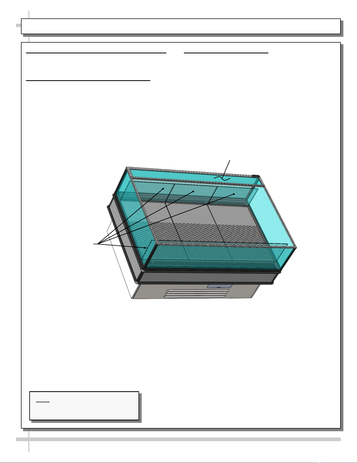
EVAPORATOR SECTION ACCESS: BAFFLED DECK PAN ASSEMBLIES / THERMOMETER
11
Caution! Turn Off Power To Unit Before Removing
Deck Pans! Rotating Fans Can Cause Severe Injury!
Evaporator Section Access
1. Baffled Deck Pan Assemblies Removal
• Baffled deck pan assemblies consist of pan, acrylic
product stop and finger hole inserts.
• To remove, lift pans at location nearest
thermometer UP AND OVER acrylic product stop.
• Remove remaining baffled deck pan assemblies in
like manner.
• See below illustration.
2. Thermometer
• Thermometer is located on air return duct (as illustrated
below).
• Thermometer reflects internal air temperature only (not
actual food temperature).
• Use probe thermometers to determine actual product
temperatures.
Random Model Is Shown Below. It May
Not Exactly Reflect Every Feature
Or Option Of Your Particular Model.
Finger
Hole (Typ.)
Baffled Deck
Pans (Typ.)
Acrylic Product
Stop (Typ.)
Acrylic Product
Stop (Typ.)
Sub-Deck
Sub-Deck
Baffled Deck
Pan (Typ.)
Baffled
Deck Pan
Thermometer
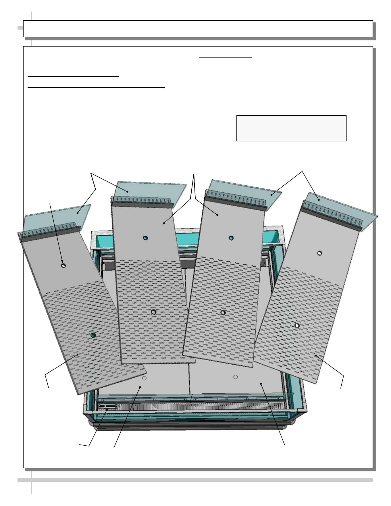
EVAPORATOR SECTION ACCESS, CONT’D: LOWER DECK PAN REMOVAL / EVAPORATOR COMP.
12
Caution! Turn Off Power To Unit Before Removing
Deck Pans! Rotating Fans Can Cause Severe Injury!
Evaporator Section Access, Cont’d
3. Lower Deck Pan Removal
• After baffled deck pans have been removed, you must
remove lower deck pans.
• Finger holes are provided for easy removal.
• Place in location away from foot traffic while cleaning
or servicing unit.
• See illustration below.
4. Evaporator Section Components
• After lower deck pans have been removed, you may
access TXV, drain, refrigeration lines, trough and drain
(as illustrated below).
• Follow cleaning and/or servicing instructions for
evaporator section components.
• After cleaning/servicing unit, return components in
reverse order they were removed.
Air Discharge
Thermometer
Refrigeration Lines
Trough
Drain
Tub
TXV
Wiring
Route
Lower
Deck Pans
Evaporator
Coil Fan
Evaporator Coil
Shroud
Random Model Is Shown Below. It May
Not Exactly Reflect Every Feature
Or Option Of Your Particular Model.
Deck Pan
Support
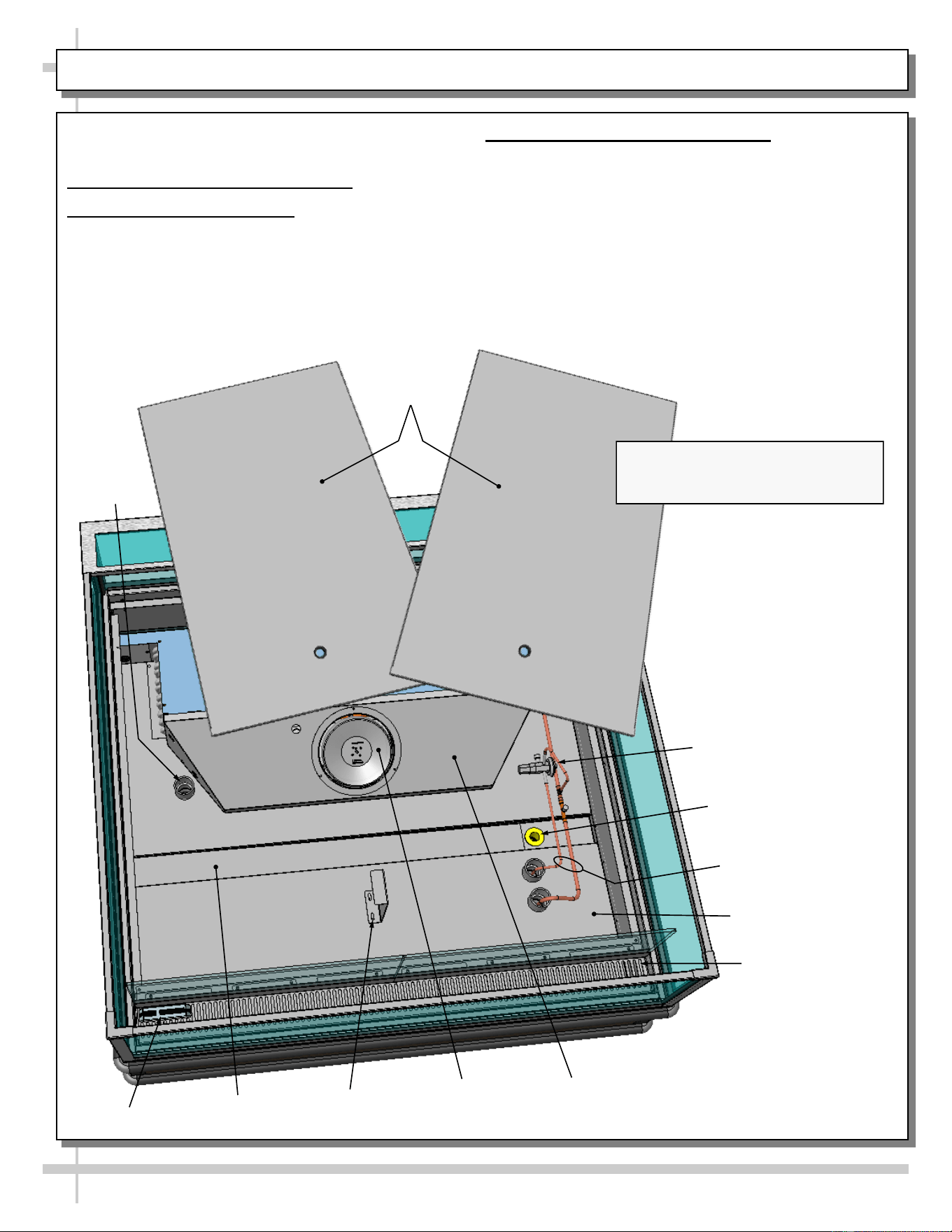
LOAD LIMIT (LOAD LINE) GUIDELINES / CASE FRONT & REAR DESIGNATIONS / THERMOMETER
13
1. Load Limit (Load Line) Guidelines
Caution! Stacking food beyond the load line will prevent food from being at proper temperature.
• Load line is placed at location to allow proper refrigerated airflow to product.
• Load line will be etched in acrylic on both sides of case.
• NEVER set product on air return grille!
• See illustration below for load line locations.
2. Case Front & Rear Designations
• Case front is the controls side and air intake side of case. This is also the side of case that the condensing
package is slid out for cleaning and/or servicing.
• Case rear is the air discharge side of case.
• See illustration below.
Load Line
Load Line
Case Rear
(Air Discharge)
Note: Illustrations Shown May Not
Reflect Every Feature Or Option
Of Your Particular Case.
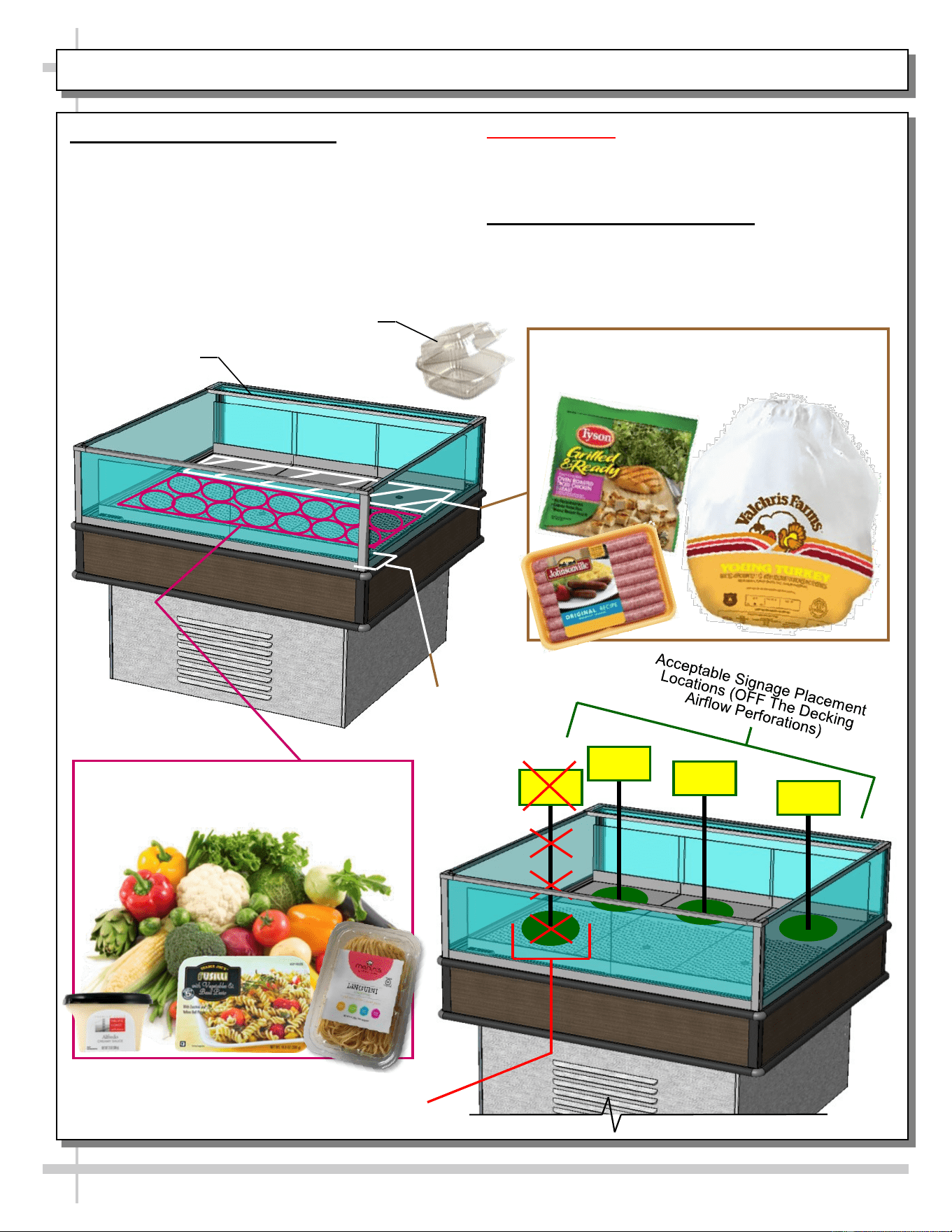
PRODUCT AND SIGNAGE PLACEMENT GUIDELINES
14
1. Product Placement Guidelines
• Higher protein products require the coolest air
temperatures on a case.
• Area of case nearest air discharge remains coolest
during regular operation.
• Place high protein products (such as poultry, sausage
and other meats) closer to air discharge side of
merchandiser.
• Place low protein products (such as produce, sauces
and pastas closer to air return side of merchandiser).
Unacceptable Signage Placement Location
(On Decking Airflow Perforations)
Cautionary Notes:
> NEVER set product on air return grille.
> Food in ‘clamshell containers’ must be placed at case
rear to insure proper cooling of its product!
2. Signage Placement Guidelines
• Airflow perforations through decking help keep product
at proper temperatures.
• DO NOT block airflow perforations on decking!
Air Discharge
Air Return
Place High Protein Products Such As Poultry,
Sausage and Other Meats Here (Closer To
Air Discharge Side of Merchandiser)
Place Low Protein Products Such As
Produce, Sauces and Pastas Here (Closer
To Air Return Side Of Merchandiser)
Sample Clamshell Container
--- Case Front ---
--- Case Rear ---
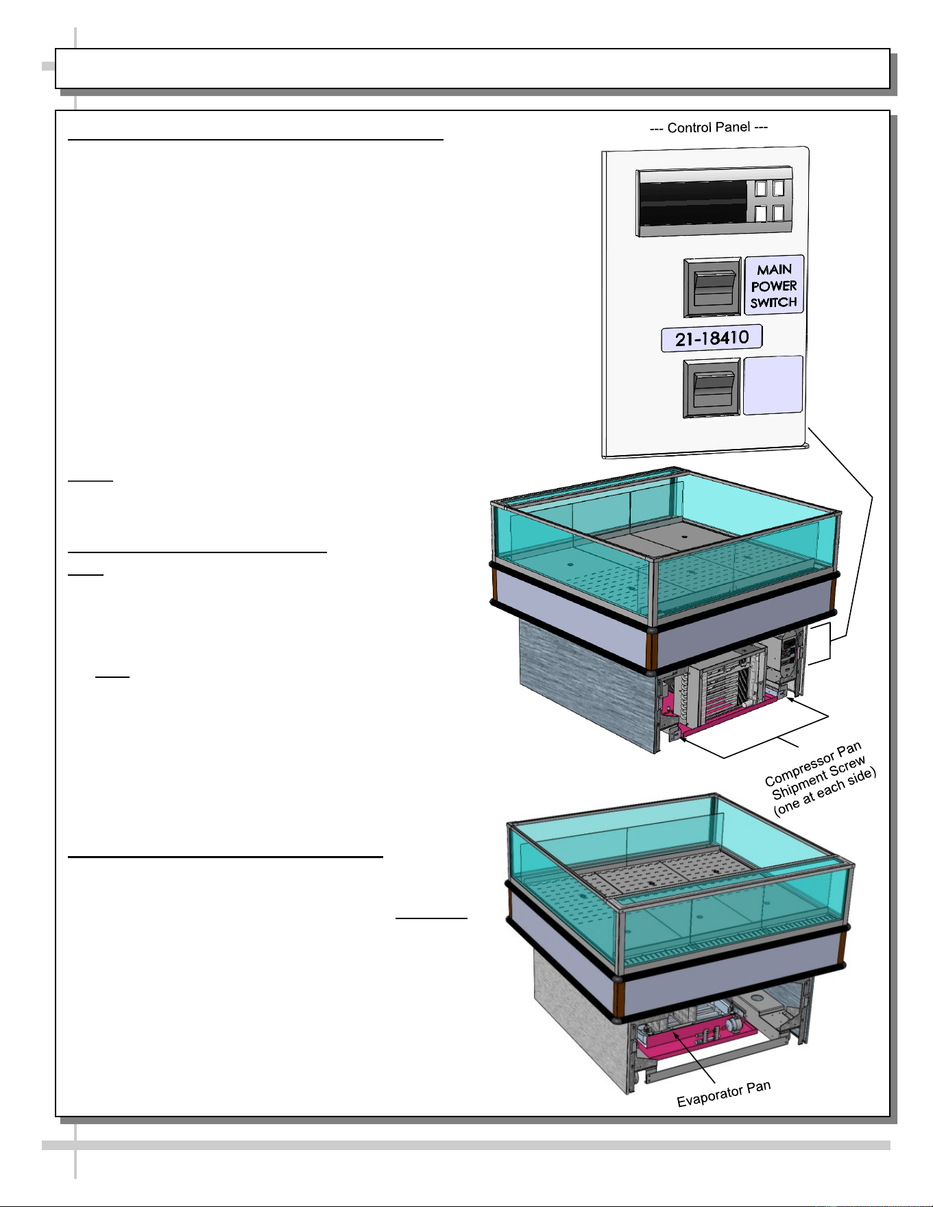
15
REFRIGERATION FUNDAMENTALS - REFRIG. PKG., TEMP. CONTROLLER, EVAP. PAN ACCESS
1. Temp. Controller (Self-Contained Units Only)
• Temperature controller is located behind the
front panel. See illustration at right.
• Temperature / Defrost control settings are
programmable from this location.
• Case Temperature Set Point is set at the factory,
as determined by case size & sensor probe location.
• Temperature is controlled by thermostat.
• If a temperature setting change is required, follow
instructions regarding Temperature Control
Programming Steps in the technical information
section of this operating manual.
• If service is required to the temperature control unit,
call Structural Concepts Corporation. Maintenance
should be performed by a certified technician.
• The toll-free number is listed in the Technical
Service section of this manual.
• See Temperature Controller section in this manual.
NOTE: Thermometers located in the refrigerated
compartment are for monitoring warmest air temperature
in accordance with NSF Std. 7
2. Refrigeration Package Access
Note: Servicing to be accomplished by licensed
electrical / refrigeration contractor.
Pull Out Refrigeration Package
• Slide grille (located opposite to temperature controls)
up and out. No tools are required.
• Note: At initial slide-out, it may be necessary to
remove compressor pan shipment screws (see
illustration at right for location).
• Refrigerant lines are flexible to facilitate rear access
maintenance.
• Plastic glides are mounted at base to assist in sliding
the condenser out for access.
• Slide condenser unit out 12 to 18 inches to access
high pressure service connection.
3. Evaporator Pan Access At Case Rear
• Turn off main power switch; allow evaporator
pan to cool.
• Evaporator pan is generally accessible by sliding out
condenser package from under case (as shown in
mid-right illustration).
• However, by removing air intake grille, it is possible to
access evaporator pan for cleaning.
• Replace rear intake grille to case when completed.
• See illustration at lower-right.
O = 38 °F
MEAT & DAIRY
I = 41 °F
PRODUCE
O
I
16
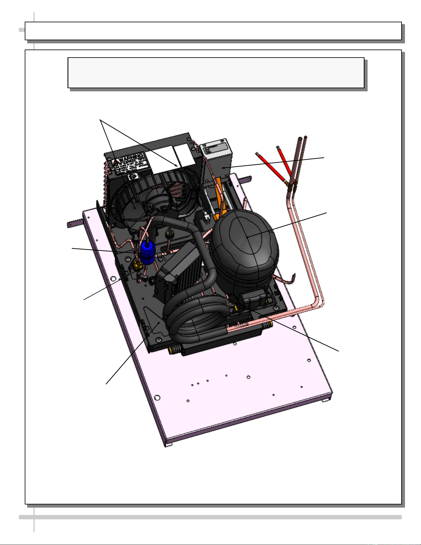
CONDENSER PACKAGE EXPLODED PICTORIAL - WITH SMALL HOT GAS LOOP CONDENSATE UNIT
Illustration Below May Not Reflect Every Feature Or Option Of Your Particular Case.
See Previous Page AND Next Page For Alternate Condenser Package Designs.
Sight Glass
Condensing Coil
(and Internal Fan)
Compressor
Filter Drier
Hot Gas Loop
Condensate Pan
Compressor
Electrical Box
Condensate
Overflow Pan
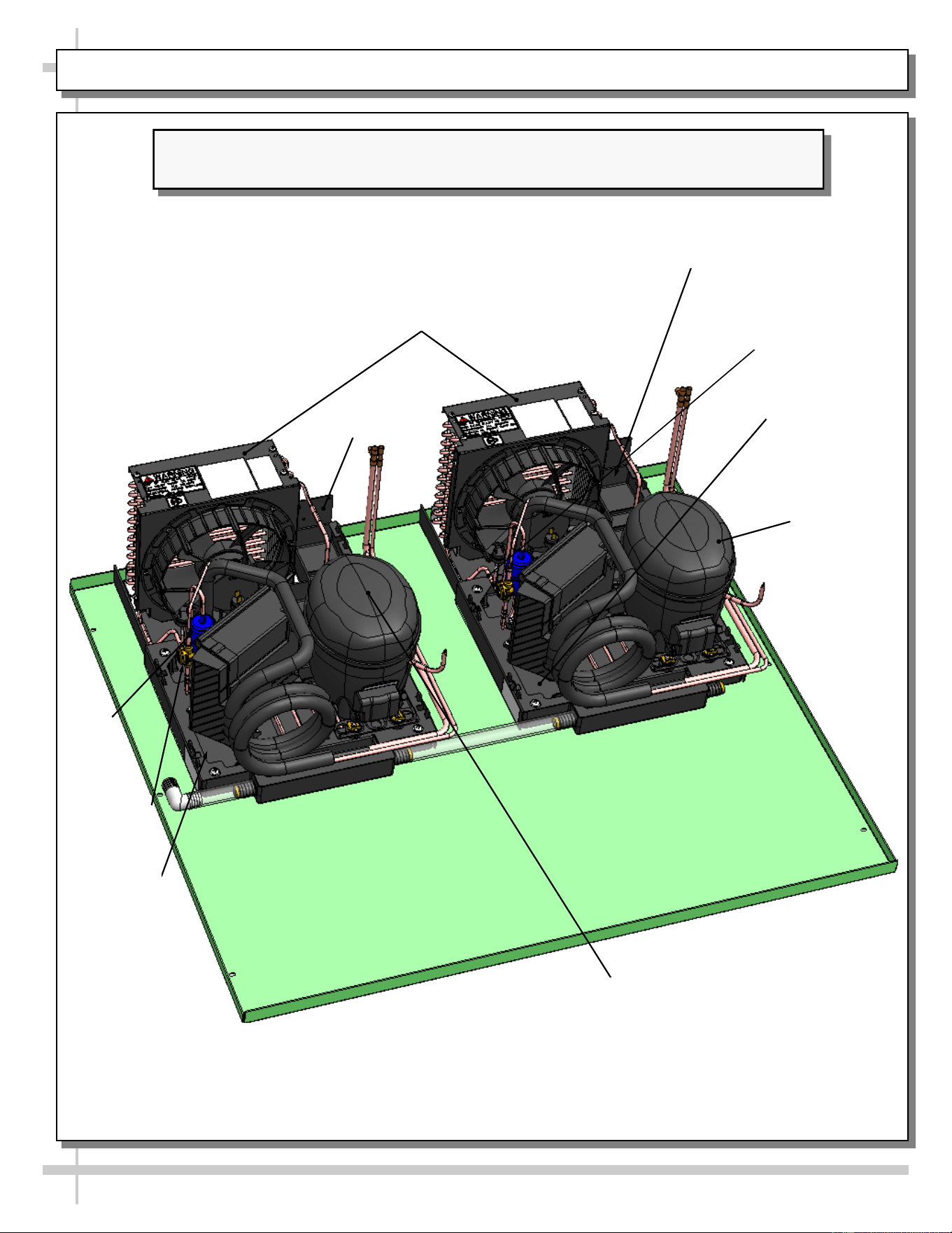
17
CONDENSER PACKAGE EXPLODED PICTORIAL - WITH SMALL HOT GAS LOOP CONDENSATE UNIT
Illustration Below May Not Reflect Every Feature Or Option Of Your Particular Case.
See Previous Page AND Next Page For Alternate Condenser Package Designs.
Sight Glass
Condensing Coil
(and Internal Fan)
Compressor
Filter
Drier
Hot Gas Loop
Condensate
Pan
Compressor
Electrical Box
Compressor
Electrical Box
Condensate
Overflow Pan
Condensate
Overflow Pan
Compressor
18
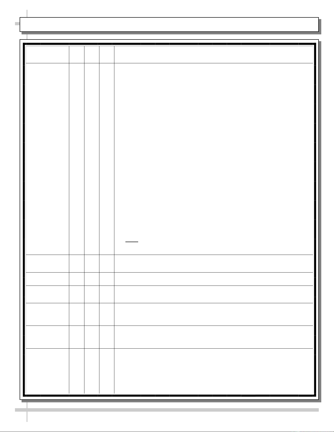
CLEANING SCHEDULE (“D” = Daily / “W” = Weekly / “M” = Monthly)
Area/
Component
D W M Task
Clean Acrylic X
Acrylic MUST BE cleaned according to these instructions to prevent
acrylic surfaces from becoming cloudy, dull or scratched.
• DO NOT use a dry cloth or paper towel to wipe off dust or debris
(this can rub dirt and dust into the acrylic surface).
• BEFORE cleaning, use air pressure or feather duster to blow or
remove all dust and debris.
• DO NOT use household cleaners (such as ammonia, bleach,
Windex® or Formula 409®).
• DO NOT use powder scouring cleansers (such as Comet® or Ajax®)
or other abrasive cleansers on acrylic!
• DO use a soft sponge or cloth with a mix of warm (not hot!) water and
mild soap solution (such as Palmolive®, Joy®, Dawn®, or Ajax®
dishwashing detergents) to wipe down surfaces.
• DO use acrylic cleaning product such as Brillianize®, or Novus® #1
(if you want to purchase cleaners specifically formulated to clean
acrylic).
• DO rinse out the soft sponge or cloth often in the solution while
cleaning the acrylic. This keeps the dust and debris from being
collected in one area and relocated to another!
• DO wipe dry with a microfiber cloth, microfiber terry cloth or chamois
cloth to dry acrylic surfaces.
• DO NOT wipe dry with a dry cloth or paper towel!
• DO use products such as Novus® #2 to remove fine scratches,
haziness and abrasions that can form in acrylic. Also, Pittman ALR®
may be used to removed oxidation (cloudy or dull acrylic surfaces).
• Note: Model MI6R.6620 adjustable acrylic dividers may be removed,
submersed in warm, soapy water, rinsed, dried and returned to case.
Clean Case
Interior
X Shelves and decks can be cleaned with a warm soap and water solution.
X Remove the decks and clean with soap and water.
X
Vacuum tub under deck. Clean with soap and water. Wipe dry with clean
cloth.
X
Keep drains clean and free of debris which could clog the drain and rob
the case of needed refrigeration.
Clean
Condensing
Coil
X Clean the condenser coil.
X
Using air pressure if available, or an industrial strength vacuum, clean
the dust and dirt that collects on the condenser coil. Be careful not to
damage the fins on the coil.
19
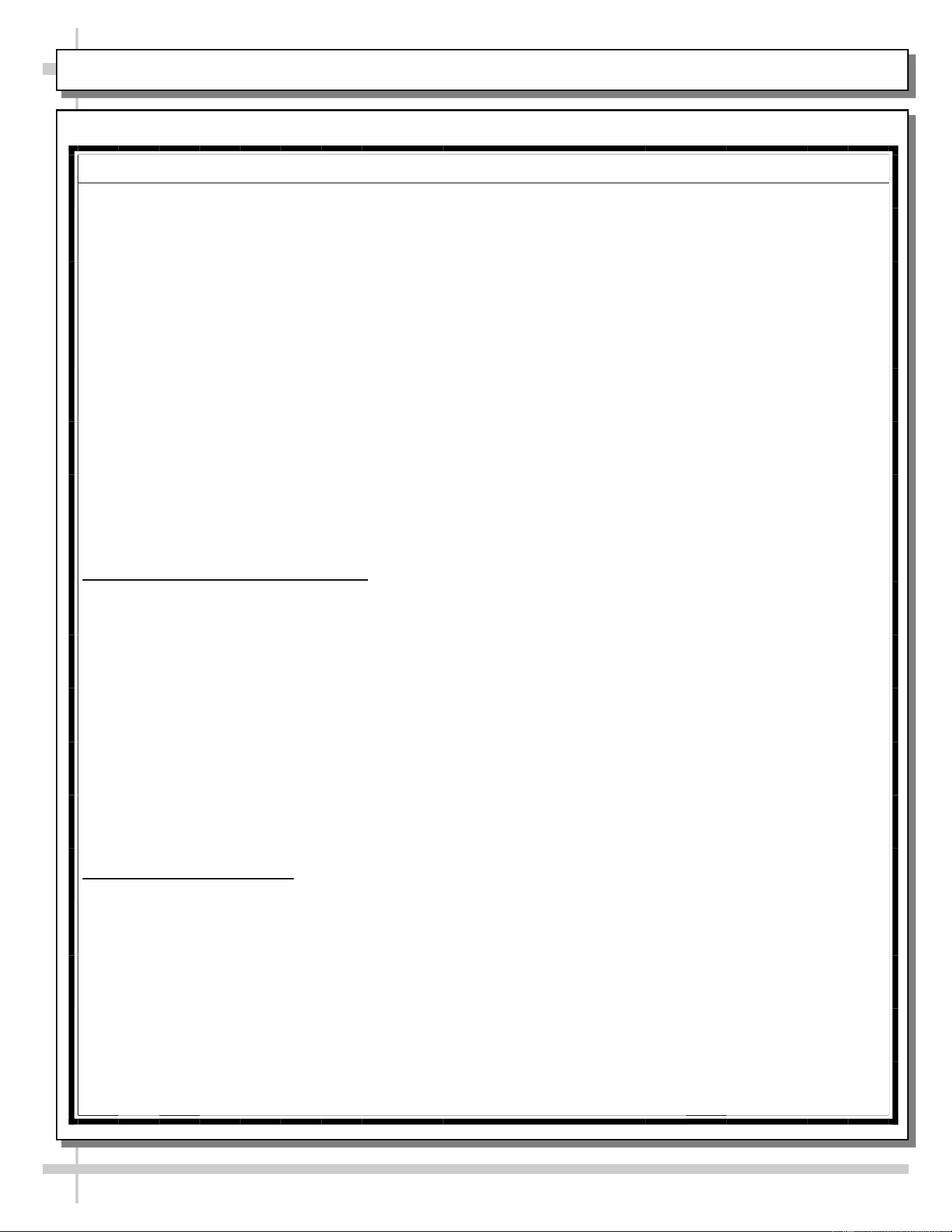
PREVENTIVE MAINTENANCE (TO BE PERFORMED BY TRAINED SERVICE PROVIDER)-2 of 2
Area of
Case
FREQ. INSTRUCTIONS
Case
Exterior
Monthly Condensing Coil:
• Remove panel to access area by lifting up and off (no screw removal is
required; simply lift up and off)
• Use air pressure or industrial strength vacuum; clean dust and dirt that may
collect on the condenser coil.
• Caution! Airborne dust can contaminating food! Use wet rags to cover area
where air pressure is blowing.
• Warning! Coil fins are sharp. Handle with care!
• Return panel to case.
Quarterly Condensate Package / Overflow Condensate Pan / Compressor Area: Caution!
Be certain to disconnect power from case before cleaning condensate package!
• Slide/roll compressor package out from under case.
• Use a scrub-brush and a de-scaling solution such as CLR® (to prevent
corrosion, lime and rust). Follow instructions as to proper dilution, safety
precautions and scrubbing method.
• Electric heater coil condensate pans can be removed and cleaned.
• After thoroughly cleaning pan with scrub-brush and solution, rinse thoroughly
with clean water (in spray bottle) and wipe dry with sponge or paper towel.
• Use moist cloth to wipe off dust & debris that collects on various parts (fans,
sight glass, overflow pan, etc.).
• Slide refrigeration assembly back under case.
• Replace lower panel via hook/magnet method (no screws required).
• Check if wicking material is dirty, worn, tattered or disintegrating. If so, it must be
replaced. Contact Structural Concepts for replacement wicking material (toll-free
number is listed on the last page of this operating manual).
Quarterly Under Case Cleaning: Once condenser package is clear of unit, vacuum under
case to remove dust and dirt that collects under case.
Case
Interior
Quarterly Tub, Coil, Drain, Fan Blade, Motor, Bracket:
Disconnect power from the case before cleaning tub, coil, fan, motor and drain area!
• Remove decking, sub-deck and fan shroud.
• Use vacuum to clean evaporator coils.
• Clean tub, coil and drain with warm water, clean cloth, brush and mild soap
solution.
• Remove any debris that may clog drain.
• Clean fan blade, motor and bracket by wiping down with moist cloth.
Quarterly Honeycomb Air Diffusers:
• Remove honeycomb air diffuser from case.
• Vacuum.
• Clean with warm water and soap.
• Return to case.
• See HONEYCOMB AIR DIFFUSER - MODEL MI6R.6620, MI6R.7065, ET AL.
in manual for removal/replacement illustrations.
WARNING! TURN OFF CASE BEFORE PERFORMING PREVENTIVE MAINTENANCE!
WARNING! TURN OFF CASE BEFORE PERFORMING PREVENTIVE MAINTENANCE!
Maintenance and Service Notes
• All maintenance staff and others working in the local area shall be instructed on the nature of work
being carried out. Work in confined spaces shall be avoided.
• The area shall be checked with an appropriate refrigerant detector prior to and during work, to ensure
the technician is aware of potentially toxic or flammable atmospheres. Ensure that the leak detection
equipment being used is suitable for use with all applicable refrigerants, i.e., nonsparking, adequately
sealed, or intrinsically safe.
• If any hot work is to be conducted on the refrigerating equipment or any associated parts, appropriate
fire extinguishing equipment shall be available on hand. A dry chemical or CO
2
fire extinguisher
should be adjacent to the charging area.
• No person carrying out work in relation to a refrigerating system which involves exposing any pipe
work shall use any sources of ignition in such a manner that it may lead to the risk of fire or explosion.
All possible ignition sources, including cigarette smoking should be keep sufficiently far away from the
site of installation, repairing, removing and disposal, during which refrigerant can possible be released
to the surround space. Prior to work taking place, the area around the equipment shall be surveyed to
make sure that there are no flammable hazards or ignition risks. “No Smoking” signs shall be dis-
played.
• Ensure that the area is in the open or that it is adequately ventilated before breaking into the system
or conducting any hot work. A degree of ventilation shall continue during the period that the work is
carried out. The ventilation should safely disperse any released refrigerant and preferably expel it ex-
ternally into the atmosphere.
Checks to the refrigerating equipment
• Where electrical components are being changed, they shall be fit for the purpose and to the correct
specification. At all times, the manufacturer’s maintenance and service guidelines shall be followed. If
in doubt, consult the manufacturer’s technical department for assistance.
• The following check shall be applied to installation using FLAMMABLE REFRIGERANTS:
a) the actual REFRIGERANT CHARGE is in accordance with the room size within which the re-
frigerant containing parts are installed;
b) the ventilation machinery and outlets are operating adequately and are not obstructed;
c) if an indirect refrigeration circuit is being used, the secondary circuit shall be checked for the
presence of refrigerant;
d) marking to the equipment continues to be visible and legible. Markings and signs that are illegi-
ble shall be corrected;
e) refrigerating pipe or components are installed in a position where they are unlikely to be ex-
posed to any substance which may corrode refrigerant containing components, unless the
components are constructed of materials which are inherently resistant to being corroded or
are suitably protected against being so corroded.
Checks to electrical devices
• Repair and maintenance to electrical components shall include initial safety checks and component
inspection procedures. If a fault exists that could compromise safety, then no electrical supply shall be
connected to the circuit until it is satisfactorily dealt with. If the fault cannot be corrected immediately
but it is necessary to continue operation, an adequate temporary solution shall be used. This shall be
reported to the owner of the equipment, so all parties are advised.
• Initial safety checks shall include:
a) that capacitors are discharged: this shall be done in a safe manner to avoid possibility of
sparking;
b) that no live electrical components and wiring are exposed while charging, recovering or purg-
ing the system;
c) that there is continuity of earth bonding.
PREVENTIVE MAINTENANCE - TO BE PERFORMED BY TRAINED SERVICE PROVIDERS ONLY - 1 of 6
20
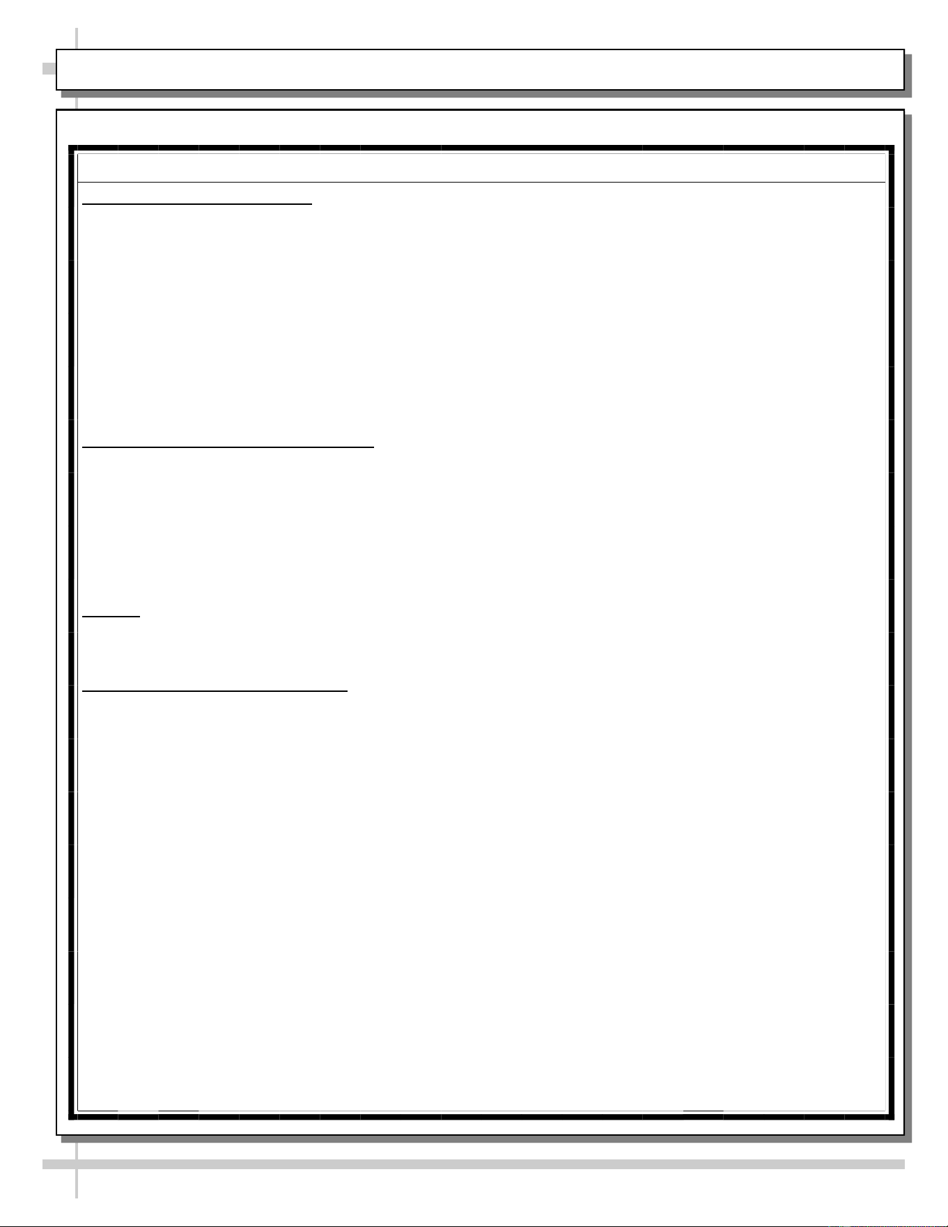
PREVENTIVE MAINTENANCE (TO BE PERFORMED BY TRAINED SERVICE PROVIDER)-2 of 2
Area of
Case
FREQ. INSTRUCTIONS
Case
Exterior
Monthly Condensing Coil:
• Remove panel to access area by lifting up and off (no screw removal is
required; simply lift up and off)
• Use air pressure or industrial strength vacuum; clean dust and dirt that may
collect on the condenser coil.
• Caution! Airborne dust can contaminating food! Use wet rags to cover area
where air pressure is blowing.
• Warning! Coil fins are sharp. Handle with care!
• Return panel to case.
Quarterly Condensate Package / Overflow Condensate Pan / Compressor Area: Caution!
Be certain to disconnect power from case before cleaning condensate package!
• Slide/roll compressor package out from under case.
• Use a scrub-brush and a de-scaling solution such as CLR® (to prevent
corrosion, lime and rust). Follow instructions as to proper dilution, safety
precautions and scrubbing method.
• Electric heater coil condensate pans can be removed and cleaned.
• After thoroughly cleaning pan with scrub-brush and solution, rinse thoroughly
with clean water (in spray bottle) and wipe dry with sponge or paper towel.
• Use moist cloth to wipe off dust & debris that collects on various parts (fans,
sight glass, overflow pan, etc.).
• Slide refrigeration assembly back under case.
• Replace lower panel via hook/magnet method (no screws required).
• Check if wicking material is dirty, worn, tattered or disintegrating. If so, it must be
replaced. Contact Structural Concepts for replacement wicking material (toll-free
number is listed on the last page of this operating manual).
Quarterly Under Case Cleaning: Once condenser package is clear of unit, vacuum under
case to remove dust and dirt that collects under case.
Case
Interior
Quarterly Tub, Coil, Drain, Fan Blade, Motor, Bracket:
Disconnect power from the case before cleaning tub, coil, fan, motor and drain area!
• Remove decking, sub-deck and fan shroud.
• Use vacuum to clean evaporator coils.
• Clean tub, coil and drain with warm water, clean cloth, brush and mild soap
solution.
• Remove any debris that may clog drain.
• Clean fan blade, motor and bracket by wiping down with moist cloth.
Quarterly Honeycomb Air Diffusers:
• Remove honeycomb air diffuser from case.
• Vacuum.
• Clean with warm water and soap.
• Return to case.
• See HONEYCOMB AIR DIFFUSER - MODEL MI6R.6620, MI6R.7065, ET AL.
in manual for removal/replacement illustrations.
WARNING! TURN OFF CASE BEFORE PERFORMING PREVENTIVE MAINTENANCE!
WARNING! TURN OFF CASE BEFORE PERFORMING PREVENTIVE MAINTENANCE!
Maintenance and Service Notes
Repairs to sealed components
• During repairs to sealed components, all electrical supplies shall be disconnected from the equipment
being worked upon prior to any removal of sealed covers, etc. If it is absolutely necessary to have an
electrical supply to equipment during servicing, then a permanent opening form of leak detection shall
be located at the most critical point to warn of a potentially hazardous situation.
• Particular attention shall be paid to the following to ensure that by working on electrical components,
the casing is not altered in such a way that the level of protection is affected. This shall include dam-
age to cables, excessive number and connections, terminals not made to original specification, dam-
age to seals, incorrect fitting of glands, etc.
• Ensure that the apparatus is mounted securely.
• Ensure that seals or sealing materials have not degraded to the point that they no longer serve the
purpose of preventing the ingress of flammable atmospheres. Replacement parts shall be in accord-
ance with the manufacturer’s specifications.
Repair to intrinsically safe components
• Do not apply any permanent inductive or capacitance loads to the circuit without ensuring that this will
not exceed the permissible voltage and current permitted for the equipment in use.
• Intrinsically safe components are the only types that can be worked on while live in the presence of a
flammable atmosphere. The test apparatus shall be at the correct rating.
• Replace components only with parts specified by the manufacturer. Other parts can result in the igni-
tion of refrigerant in the atmosphere from a leak.
• NOTE The use of silicon sealant can inhibit the effectiveness of some types of leak detection equip-
ment. Intrinsically safe components do not have to be isolated prior to working on them.
Cabling
• Check that cabling will not be subject to wear, corrosion, excessive pressure, vibration, sharp edges,
or any other adverse environmental effects. The check shall also take into account the effects of aging
or continual vibration from sources such as compressors or fans.
Detection of flammable refrigerants
• Under no circumstances shall potential sources of ignition be used in the searching for or detection of
refrigerant leaks. A halide torch (or any other detector using a naked flame) shall not be used.
• The following lead detection methods are deemed acceptable for all refrigerant systems.
• Electronic leak detectors may be used to detect refrigerant leaks but, in the case of FLAMMABLE RE-
FRIGERANTS the sensitivity might not be adequate, or might need recalibration. (Detection equip-
ment shall be calibrated in a refrigerant-free area.) Ensure that the detector is not a potential source of
ignition and is suitable for the refrigerant used. Leak detection equipment shall be set at a percentage
of the LFL of the refrigerant and shall be calibrated to the refrigerant employed, and the appropriate
percentage of gas (25% maximum) is confirmed.
• Leak detection fluids are also suitable for use with most refrigerants but the use of detergents contain-
ing chlorine shall be avoided as the chlorine can react with the refrigerant and corrode the copper pipe
-work.
• NOTE examples of leak detection fluids are
-bubble method.
-fluorescent method agents.
• If a leak is suspected, all naked flames shall be removed/extinguished.
• If a leakage of refrigerant is found which requires brazing, all of the refrigerant shall be recovered from
the system, or isolated (by means of shut off valves) in a part of the system remote from the leak. Re-
moval of refrigerant shall be according to the removal and evacuation procedures below.
PREVENTIVE MAINTENANCE - TO BE PERFORMED BY TRAINED SERVICE PROVIDERS ONLY - 2 of 6
21
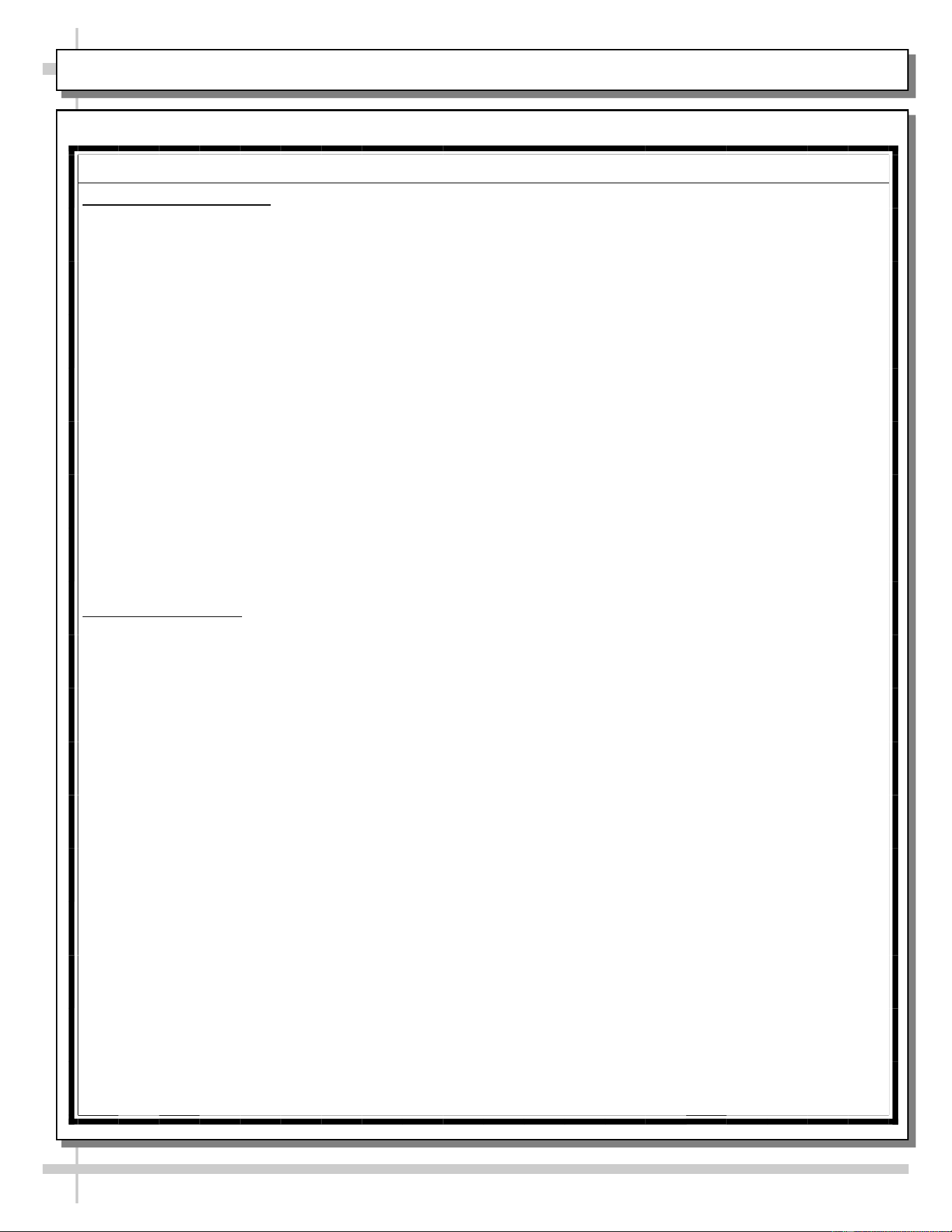
PREVENTIVE MAINTENANCE (TO BE PERFORMED BY TRAINED SERVICE PROVIDER)-2 of 2
Area of
Case
FREQ. INSTRUCTIONS
Case
Exterior
Monthly Condensing Coil:
• Remove panel to access area by lifting up and off (no screw removal is
required; simply lift up and off)
• Use air pressure or industrial strength vacuum; clean dust and dirt that may
collect on the condenser coil.
• Caution! Airborne dust can contaminating food! Use wet rags to cover area
where air pressure is blowing.
• Warning! Coil fins are sharp. Handle with care!
• Return panel to case.
Quarterly Condensate Package / Overflow Condensate Pan / Compressor Area: Caution!
Be certain to disconnect power from case before cleaning condensate package!
• Slide/roll compressor package out from under case.
• Use a scrub-brush and a de-scaling solution such as CLR® (to prevent
corrosion, lime and rust). Follow instructions as to proper dilution, safety
precautions and scrubbing method.
• Electric heater coil condensate pans can be removed and cleaned.
• After thoroughly cleaning pan with scrub-brush and solution, rinse thoroughly
with clean water (in spray bottle) and wipe dry with sponge or paper towel.
• Use moist cloth to wipe off dust & debris that collects on various parts (fans,
sight glass, overflow pan, etc.).
• Slide refrigeration assembly back under case.
• Replace lower panel via hook/magnet method (no screws required).
• Check if wicking material is dirty, worn, tattered or disintegrating. If so, it must be
replaced. Contact Structural Concepts for replacement wicking material (toll-free
number is listed on the last page of this operating manual).
Quarterly Under Case Cleaning: Once condenser package is clear of unit, vacuum under
case to remove dust and dirt that collects under case.
Case
Interior
Quarterly Tub, Coil, Drain, Fan Blade, Motor, Bracket:
Disconnect power from the case before cleaning tub, coil, fan, motor and drain area!
• Remove decking, sub-deck and fan shroud.
• Use vacuum to clean evaporator coils.
• Clean tub, coil and drain with warm water, clean cloth, brush and mild soap
solution.
• Remove any debris that may clog drain.
• Clean fan blade, motor and bracket by wiping down with moist cloth.
Quarterly Honeycomb Air Diffusers:
• Remove honeycomb air diffuser from case.
• Vacuum.
• Clean with warm water and soap.
• Return to case.
• See HONEYCOMB AIR DIFFUSER - MODEL MI6R.6620, MI6R.7065, ET AL.
in manual for removal/replacement illustrations.
WARNING! TURN OFF CASE BEFORE PERFORMING PREVENTIVE MAINTENANCE!
WARNING! TURN OFF CASE BEFORE PERFORMING PREVENTIVE MAINTENANCE!
Maintenance and Service Notes
Removal and evacuation
• When breaking into the refrigerant circuit to make repairs-or for any other purpose-conventional proce-
dures shall be used. However, for flammable refrigerants it is important that the best practice be fol-
lowed, since flammability is a consideration. The following procedure shall be adhered to:
a) safely remove refrigerant following local and national regulations;
b) purge the circuit with inert gas;
c) evacuate (optional for A2L);
d) purge with inert gas (optional for A2L);
e) open the circuit by cutting or brazing.
• The refrigerant change shall be recovered into the correct recovery cylinders if venting is not allowed
by local and national codes. For appliances containing flammable refrigerants, the system shall be
purged with oxygen-free nitrogen to render the appliance safe for flammable refrigerants. This process
might need to be repeated several times. Compressed air or oxygen shall not be used for purging re-
frigerant systems.
• For appliances containing flammable refrigerants, refrigerant purging shall be achieved by breaking
the vacuum in the system with oxygen-free nitrogen and continuing to fill until the working pressure is
achieved, then venting to atmosphere, and finally pulling down to a vacuum (optional for A2L). This
process shall be repeated until no refrigerant is within the system (optional for A2L). When the final
oxygen-free nitrogen change is used, the system shall be vented down to atmospheric pressure to
enable work to take place.
• Ensure that the outlet for the vacuum pump is not close to any potential ignition sources and that ven-
tilation is available.
Charging procedures
• In addition to conventional charging procedures, the following requirements shall be followed.
a) Ensure that contamination of different refrigerants does not occur when using charging equip-
ment. Hoses or lines shall be as short as possible to minimize the amount of refrigerant con-
tained in them.
b) Cylinders shall be kept in an appropriate position according to the instructions.
c) Ensure that the REFRIGERATING SYSTEM is earthed prior to charging the system with refrig-
erant.
d) Label the system when charging is complete (if not already).
e) Extreme care shall be taken not to overfill the REFRIGERATING SYSTEM.
• Prior to recharging the system. It shall be pressure-tested with the appropriate purging gas. The sys-
tem shall be lead-tested on completion of charging but prior to commissioning. A follow up leak test
shall be carried out prior to leaving the site.
PREVENTIVE MAINTENANCE - TO BE PERFORMED BY TRAINED SERVICE PROVIDERS ONLY - 3 of 6
22
PREVENTIVE MAINTENANCE (TO BE PERFORMED BY TRAINED SERVICE PROVIDER)-2 of 2
Area of
Case
FREQ. INSTRUCTIONS
Case
Exterior
Monthly Condensing Coil:
• Remove panel to access area by lifting up and off (no screw removal is
required; simply lift up and off)
• Use air pressure or industrial strength vacuum; clean dust and dirt that may
collect on the condenser coil.
• Caution! Airborne dust can contaminating food! Use wet rags to cover area
where air pressure is blowing.
• Warning! Coil fins are sharp. Handle with care!
• Return panel to case.
Quarterly Condensate Package / Overflow Condensate Pan / Compressor Area: Caution!
Be certain to disconnect power from case before cleaning condensate package!
• Slide/roll compressor package out from under case.
• Use a scrub-brush and a de-scaling solution such as CLR® (to prevent
corrosion, lime and rust). Follow instructions as to proper dilution, safety
precautions and scrubbing method.
• Electric heater coil condensate pans can be removed and cleaned.
• After thoroughly cleaning pan with scrub-brush and solution, rinse thoroughly
with clean water (in spray bottle) and wipe dry with sponge or paper towel.
• Use moist cloth to wipe off dust & debris that collects on various parts (fans,
sight glass, overflow pan, etc.).
• Slide refrigeration assembly back under case.
• Replace lower panel via hook/magnet method (no screws required).
• Check if wicking material is dirty, worn, tattered or disintegrating. If so, it must be
replaced. Contact Structural Concepts for replacement wicking material (toll-free
number is listed on the last page of this operating manual).
Quarterly Under Case Cleaning: Once condenser package is clear of unit, vacuum under
case to remove dust and dirt that collects under case.
Case
Interior
Quarterly Tub, Coil, Drain, Fan Blade, Motor, Bracket:
Disconnect power from the case before cleaning tub, coil, fan, motor and drain area!
• Remove decking, sub-deck and fan shroud.
• Use vacuum to clean evaporator coils.
• Clean tub, coil and drain with warm water, clean cloth, brush and mild soap
solution.
• Remove any debris that may clog drain.
• Clean fan blade, motor and bracket by wiping down with moist cloth.
Quarterly Honeycomb Air Diffusers:
• Remove honeycomb air diffuser from case.
• Vacuum.
• Clean with warm water and soap.
• Return to case.
• See HONEYCOMB AIR DIFFUSER - MODEL MI6R.6620, MI6R.7065, ET AL.
in manual for removal/replacement illustrations.
WARNING! TURN OFF CASE BEFORE PERFORMING PREVENTIVE MAINTENANCE!
WARNING! TURN OFF CASE BEFORE PERFORMING PREVENTIVE MAINTENANCE!
Maintenance and Service Notes
Decommissioning
• Before carrying out this procedure, it is essential that the technician is completely familiar with the
equipment and all its detail. I tis recommended good practice that all refrigerants are recovered safe-
ly. Prior to the task being carried out, an oil and refrigerant sample shall be taken in case analysis is
required prior to re-use of recovered refrigerant. It is essential that electrical power is available before
the task is commenced.
a) Become familiar with the equipment and its operation.
b) Isolate the system electrically.
c) Before attempting the procedure, ensure that:
i) mechanical handling equipment is available, if required, for handling refrigerant cylin-
ders;
ii) all personal protective equipment is available and being used correctly;
iii) the recovery process is supervised at all times by a competent person;
iv) recovery equipment and cylinders conform to the appropriate standards.
d) Pump down refrigerant system, if possible.
e) If a vacuum is not possible, make a manifold so that refrigerant can be removed from various
parts of the system.
f) Make sure that cylinder is situated on the scales before recovery takes place.
g) Start the recovery machine and operate in accordance with instructions.
h) Do not overfill cylinders (no more than 80% volume liquid charge).
i) Do not exceed the maximum working pressure of the cylinder, even temporarily
j) When the cylinders have been filled correctly and the process completed, make sure that the
cylinders and the equipment are removed from the site properly and all isolation valves on the
equipment are closed off.
k) Recovered refrigerant shall not be charged into another refrigerating system unless it has been
cleaned and checked.
• Equipment shall be labelled stating that it has been de-commissioned and emptied of refrigerant. The
label shall be dated and signed. For appliances containing flammable refrigerants, ensure that there
are labels on the equipment stating the equipment contains flammable refrigerant.
PREVENTIVE MAINTENANCE - TO BE PERFORMED BY TRAINED SERVICE PROVIDERS ONLY - 4 of 6
23
PREVENTIVE MAINTENANCE (TO BE PERFORMED BY TRAINED SERVICE PROVIDER)-2 of 2
Area of
Case
FREQ. INSTRUCTIONS
Case
Exterior
Monthly Condensing Coil:
• Remove panel to access area by lifting up and off (no screw removal is
required; simply lift up and off)
• Use air pressure or industrial strength vacuum; clean dust and dirt that may
collect on the condenser coil.
• Caution! Airborne dust can contaminating food! Use wet rags to cover area
where air pressure is blowing.
• Warning! Coil fins are sharp. Handle with care!
• Return panel to case.
Quarterly Condensate Package / Overflow Condensate Pan / Compressor Area: Caution!
Be certain to disconnect power from case before cleaning condensate package!
• Slide/roll compressor package out from under case.
• Use a scrub-brush and a de-scaling solution such as CLR® (to prevent
corrosion, lime and rust). Follow instructions as to proper dilution, safety
precautions and scrubbing method.
• Electric heater coil condensate pans can be removed and cleaned.
• After thoroughly cleaning pan with scrub-brush and solution, rinse thoroughly
with clean water (in spray bottle) and wipe dry with sponge or paper towel.
• Use moist cloth to wipe off dust & debris that collects on various parts (fans,
sight glass, overflow pan, etc.).
• Slide refrigeration assembly back under case.
• Replace lower panel via hook/magnet method (no screws required).
• Check if wicking material is dirty, worn, tattered or disintegrating. If so, it must be
replaced. Contact Structural Concepts for replacement wicking material (toll-free
number is listed on the last page of this operating manual).
Quarterly Under Case Cleaning: Once condenser package is clear of unit, vacuum under
case to remove dust and dirt that collects under case.
Case
Interior
Quarterly Tub, Coil, Drain, Fan Blade, Motor, Bracket:
Disconnect power from the case before cleaning tub, coil, fan, motor and drain area!
• Remove decking, sub-deck and fan shroud.
• Use vacuum to clean evaporator coils.
• Clean tub, coil and drain with warm water, clean cloth, brush and mild soap
solution.
• Remove any debris that may clog drain.
• Clean fan blade, motor and bracket by wiping down with moist cloth.
Quarterly Honeycomb Air Diffusers:
• Remove honeycomb air diffuser from case.
• Vacuum.
• Clean with warm water and soap.
• Return to case.
• See HONEYCOMB AIR DIFFUSER - MODEL MI6R.6620, MI6R.7065, ET AL.
in manual for removal/replacement illustrations.
WARNING! TURN OFF CASE BEFORE PERFORMING PREVENTIVE MAINTENANCE!
WARNING! TURN OFF CASE BEFORE PERFORMING PREVENTIVE MAINTENANCE!
Maintenance and Service Notes
Recovery
• When removing refrigerant from a system, either for servicing or decommissioning, it is recommended
good practice that all refrigerants are removed safely.
• When transferring refrigerant into cylinders, ensure that only appropriate refrigerant recovery cylinders
are employed. Ensure that the correct number of cylinders for holding the total system charge is avail-
able. All cylinders to be used are designated for the recovered refrigerant and labeled for that refriger-
ant (i.e., special cylinders for the recovery of refrigerant). Cylinders shall be complete with pressure-
relief valve and associated shut-off valve in good working order. Empty recovery cylinders are evacu-
ated and, if possible, cooled before recovery occurs.
• The recovery equipment shall be in good working order with a set of instructions concerning the equip-
ment that is at hand and shall be suitable for the recovery of all appropriate refrigerants including,
when applicable, FLAMMABLE REFRIGERANTS. In addition, a set of calibrated weighing scales shall
be available and in good working order. Hoses shall be complete with leak-free disconnect coupling
and in good condition. Before using the recovery machine, check that it is in satisfactory working or-
der, has been properly maintained and that any associated electrical components are sealed to pre-
vent ignition in the event of refrigerant release. Consult manufacturer if in doubt.
• The recovered refrigerant shall be returned to the refrigerant supplier in the correct recovery cylinder,
and the relevant waste transfer note arranged. Do not mix refrigerants in recovery units and especially
not in cylinders.
• If compressors or compressor oils are to be removed, ensure that they have been evacuated to an
acceptable level to make certain that FLAMMABLE REFRIGERANT does not remain within the lubri-
cant. The evacuation process shall be carried out prior to returning the compressor to the suppliers.
Only electric heating to the compressor body shall be employed to accelerate this process. When oil is
drained from a system, it shall be carried out safely.
PREVENTIVE MAINTENANCE - TO BE PERFORMED BY TRAINED SERVICE PROVIDERS ONLY - 5 of 6
24
PREVENTIVE MAINTENANCE - TO BE PERFORMED BY TRAINED SERVICE PROVIDERS ONLY - 6 of 6
Area of
Case
FREQ. INSTRUCTIONS
Case
Exterior
Monthly Condensing Coil:
• Remove panel to access area by lifting up and off (no screw removal is
required; simply lift up and off)
• Use air pressure or industrial strength vacuum; clean dust and dirt that may
collect on the condenser coil.
• Caution! Airborne dust can contaminating food! Use wet rags to cover area
where air pressure is blowing.
• Warning! Coil fins are sharp. Handle with care!
• Return panel to case.
Quarterly Condensate Package / Overflow Condensate Pan / Compressor Area: Caution!
Be certain to disconnect power from case before cleaning condensate package!
• Slide/roll compressor package out from under case.
• Use a scrub-brush and a de-scaling solution such as CLR® (to prevent
corrosion, lime and rust). Follow instructions as to proper dilution, safety
precautions and scrubbing method.
• Electric heater coil condensate pans can be removed and cleaned.
• After thoroughly cleaning pan with scrub-brush and solution, rinse thoroughly
with clean water (in spray bottle) and wipe dry with sponge or paper towel.
• Use moist cloth to wipe off dust & debris that collects on various parts (fans,
sight glass, overflow pan, etc.).
• Slide refrigeration assembly back under case.
• Replace lower panel via hook/magnet method (no screws required).
• Check if wicking material is dirty, worn, tattered or disintegrating. If so, it must be
replaced. Contact Structural Concepts for replacement wicking material (toll-free
number is listed on the last page of this operating manual).
Quarterly Under Case Cleaning: Once condenser package is clear of unit, vacuum under
case to remove dust and dirt that collects under case.
Case
Interior
Quarterly Tub, Coil, Drain, Fan Blade, Motor, Bracket:
Disconnect power from the case before cleaning tub, coil, fan, motor and drain area!
• Remove decking, sub-deck and fan shroud.
• Use vacuum to clean evaporator coils.
• Clean tub, coil and drain with warm water, clean cloth, brush and mild soap
solution.
• Remove any debris that may clog drain.
• Clean fan blade, motor and bracket by wiping down with moist cloth.
Quarterly Honeycomb Air Diffusers:
• Remove honeycomb air diffuser from case.
• Vacuum.
• Clean with warm water and soap.
• Return to case.
• See HONEYCOMB AIR DIFFUSER - MODEL MI6R.6620, MI6R.7065, ET AL.
in manual for removal/replacement illustrations.
WARNING! TURN OFF CASE BEFORE PERFORMING PREVENTIVE MAINTENANCE!
25
TROUBLESHOOTING (GENERAL)
CONDITION TROUBLESHOOTING
Water Is On The
Floor
Check that the drain trap is free of debris.
Check that the drain hose is correctly positioned over evaporator pan (or floor drain,
for remote units).
Check store conditions. To prevent condensation in Type 1 environments,
maximum conditions are to be 55% humidity / 75 °F. For Type 2 units, maximum
conditions are to be 55% humidity / 80° F. See serial label (at case rear near main
power switch) for your case type.
Check evaporator pan float for proper operation.
Check that evaporator pan is plugged in.
Evaporator pan and/or overflow evaporator pan may be malfunctioning.
If so, water will overflow pan and seep onto flooring causing damage! Until evaporator
pan is functioning (or is replaced), the following procedures are recommended:
• Use wet-dry vacuum (or mop & bucket) to remove standing water.
• Use ‘catch pans’ for water to drain into. Swap out regularly until case has
completely drained.
Disruption of power can cause water to overflow pan and seep onto
flooring causing damage! Check that power to case is constant. Until power is
restored, following these procedures:
• Use wet-dry vacuum (or mop & bucket) to remove standing water.
• Use ‘catch pans’ for water to drain into. Swap out regularly until evaporation of
case is complete (or until power is restored).
• When power to case is restored, evaporator pan should function properly and
water will no longer overflow onto flooring.
Fan Emits
Excessive Noise
Check that the case is aligned, level and plumb.
Check evaporator fan for cleanliness.
Unplug fan motor; check motor shaft for excessive bearing wear.
Check that fan motor is securely mounted in brackets.
Verify that fan blade is securely mounted to fan motor.
Check that nothing is preventing blade rotation.
Check that the fan shroud is properly secured.
Fans Are Not
Working
Check that the MAIN power switch (if present) is on.
Check that fans are plugged in to fan shroud.
Check for foreign material obstructing fan performance.
Check that fan blade freely rotates within fan shroud.
26
TROUBLESHOOTING, GENERAL - CONTINUED
CONDITION TROUBLESHOOTING
Fan Is Not Working, Continued Check that power is going to fan
Check that fan wiring is connected on terminal blocks.
System Is Not Operating Check that the utility power is on.
Check the circuit breaker box for tripped circuits.
Case Is Not Holding Temperature If a large amount of warm product was added to the case, it will
take time for the temperature to adjust. Product should be
pre-chilled before placing in display case.
Check Temperature Controller section in this manual.
Check that the case is not in the sun or near a heat or air
conditioning vent.
If case is located near outside doors, temperature fluctuation can
hinder unit’s ability to maintain temperature.
Check air grilles for obstructions. Maintain airflow clearance of
6” (minimum) to 12” (recommended) at case front and rear.
Check sight glass for flashing and/or low charge.
Check set point Temperature; it may be adjusted too high.
Control Display Is Flashing Check Temperature Controller section in this manual.
Condensing Unit Is Not Operating
(Self-Contained Units Only)
Check Temperature Controller section in this manual.
Check that the power is turned on.
Review Temperature Controller’s Settings for accuracy.
27
SERIAL LABEL LOCATION & INFO LISTED / TECH INFO & SERVICE / REFRIGERATED CASES ONLY
--- Sample Serial Label For Refrigerated Cases ---
MODEL NRS3648RXV-SAMPLE
SERIAL NO. 12345X30DZ098765
TYPE II DISPLAY REFRIGERATOR: THIS EQUIPMENT IS INTENDED FOR USE IN AN AREA
WHERE THE ENVIRONMENTAL CONDITIONS ARE CONTROLLED AND MAINTAINED SUCH
THAT THE AMBIENT TEMPERATURE DOES NOT EXCEED 80 °F (27 °C).
888 E. Porter Rd - Muskegon, MI 49441
3048256
Conforms to UL Std. 471
Conforms to NSF/ANSI Stds. 2 & 7
CERTIFIED TO CAN/CSA
STD C22.2 NO 120
ELECTRICAL RATING
REFRIGERANT
DESIGN PRESSURE
MINIMUM CIRCUIT AMPACITY
MAXIMUM OVERCURRENT
120/1/60 16 A
R513A AMOUNT 50 OZ
HIGH 186 LOW 88
20A
20A
Super Heat Temp 6-8 °F FOR PARTS AND SERVICE
Defrost 6 defrosts per day, 45 °F CALL 1-800-433-9490
Serial Label Location & Information Listed /
Technical Information & Service
• Serial labels are affixed at a wide range of places
(on the header, near thermostat, at case rear,
behind panels/toe-kicks, on electrical boxes, etc.).
• Serial labels contain electrical, temperature and
refrigeration information, as well as regulatory
standards to which the case conforms.
• Sample serial label shown below.
• For additional technical information and service, see
the TECHNICAL SERVICE page in this manual for
instructions on contacting Structural Concepts’
Technical Service Department.
Oasis
Sample QR Code
SCAN FOR PRODUCT LITERATURE
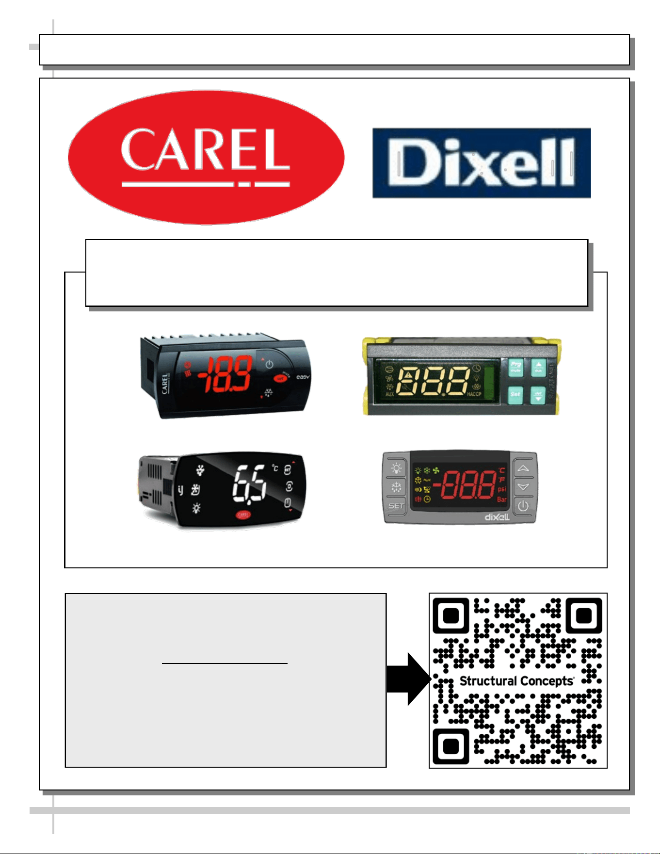
PROGRAMMABLE CONTROLLER (SELECT, CLICK ON OR SCAN QR CODE FOR INFORMATION)
28
Carel® iJF Platform
Carel® PJEZ Platform
Carel® ir33 Platform
Dixell® XM670K-XM679K Platform
To Access Information About The Programmable
Controller That Is Used On Your Case,
Follow These Instructions:
> If Viewing This Document on Smart Phone, Tablet
or Computer, Select/Click On The QR Code at Right.
> If Viewing This Document In Print (Hard Copy),
Scan The QR Code at Right With Your Smart Phone
or Tablet.
Determine Which Programmable Controller Is On Your Case (Controllers
That Are Commonly Used By Structural Concepts Are Shown Below).
Your Particular Programmable Controller May Differ.

STRUCTURAL CONCEPTS TECHNICAL SERVICE CONTACT INFORMATION & LIMITED WARRANTY
29
TECH SERVICE/WARRANTY CONTACT INFO:
1 (800) 433-9490 / EXTENSION 1
DAYS/HOURS AVAILABLE:
MONDAY - FRIDAY (CLOSED HOLIDAYS)
8:00 a.m. TO 5:00 p.m. EST
YOU MUST HAVE THE FOLLOWING INFO AVAILABLE
BEFORE CONTACTING STRUCTURAL CONCEPTS:
SERIAL NO. / MODEL NO. / STORE NO. / STORE
ADDRESS / DETAILS (PHOTOS, LEAK LOCATIONS,
DAMAGE, STORE’S AMBIENT CONDITIONS, ETC.)
To Access The Limited Warranty To Your
Case, Follow These Instructions:
> If Viewing This Document on Smart Phone,
Tablet or Computer, Select/Click On The QR
Code at Right.
> If Viewing This Document In Print (Hard
Copy), Scan The QR Code at Right With Your
Smart Phone or Tablet.