Copyright © 2025 Sol-Ark LLC
INSTALLATION GUIDE
AND USER MANUAL
COMMERCIAL & INDUSTRIAL
NORTH AMERICA
Effective Date: May 9, 2025
Sol-Ark 60K-3P-480V
EN
ii Copyright © 2025 Sol-Ark LLC
READ THE INSTRUCTIONS COMPLETELY BEFORE OPERATING THE EQUIPMENT
• Verify the utility voltage before turning ON the unit.
• For proper operation, this unit REQUIRES closed-loop communications with a compatible
high voltage battery. Visit www.Sol-Ark.com/battery-partners for a complete list of
compatible partners.
• Verify Output Voltage and “Grid Type” before connecting to the utility.
Disregarding these instructions could result in permanent damage to the
unit.

Sol-Ark 60K Installation Guide | SK140-0019 Rev 4 iii
Disclaimer
UNLESS SPECIFICALLY AGREED TO IN WRITING:
Sol-Ark assumes no responsibility or liability for any damages, property loss, personal injury, or any adverse consequences
resulting from improper use and installation of the product or the failure to adhere to the guidelines provided in this document.
Users are expressly advised to follow the instructions and guidelines outlined in the documentation accompanying the product.
Sol-Ark shall not be liable for any damages or losses incurred due to deviations from recommended usage, installation, or
maintenance procedures. By using the product, users acknowledge their understanding of these disclaimers and agree to use the
product at their own risk. Sol-Ark reserves the right to update or modify product information, specifications, and guidelines
without prior notice.
This guide is provided “as is,” without charge, and is intended solely for general informational purposes without any right or
presumption of reliance. Your sole and exclusive remedy for any defects, or other issues associated with, or related to, any sol-
product is limited and restricted solely to the limited warranty provided by Sol-Ark and included in any documentation provided
by Sol-Ark or otherwise made available on the Sol-Ark website. Failure to use the most recent, commercially available version of
Sol-Ark software may void your warranty and may cause the performance or compatibility of your Sol-Ark product to be adversely
affected. You are urged, at all times, to use the most recently available Sol-Ark software for any Sol-Ark product, including all
updates, upgrades, and other modifications of that software made commercially available by Sol-Ark.
This guide is not intended to, and does not, supersede any instructions or directions that you may have received from the
manufacturer of any other products that you may use in combination with a Sol-Ark. To the fullest extent permitted by applicable
law, Sol-Ark hereby expressly and unconditionally disclaims liability for any and all indirect, incidental, exemplary, punitive or
consequential damages.
If you are uncertain about implementing or using any of the information contained in, or made available by, this Guide, you are
urged not to continue with this Guide and immediately to contact the Sol-Ark product support. This Guide does not modify,
extend, or change the terms of any warranty that may be applicable to your Sol-Ark products, and you should carefully consult
those warranty terms to ensure that you may not be voiding or violating those warranty terms if you undertake any of the actions
referred to in this Guide.
Sol-Ark retains the right to final interpretation of this document and all related materials pertaining to this product. This document
is subject to modifications, updates, revisions, or termination without prior notice. For the latest product information, please visit
Sol-Ark’s official website. www.Sol-Ark.com
Any action related to the information included in this Guide shall be governed by the internal laws of the State of Texas, United
States of America, without giving effect to any conflicts of laws principles. Any action, suit, or other legal proceeding that is
commenced to resolve any matter related to this Guide shall be commenced solely and exclusively in a state court sitting in Collin
County, Texas (or, if appropriate, a federal court located within Collin County in the Eastern District of Texas), and you hereby
consent to the personal jurisdiction of those courts.
This manual is only for use with the 60K-3P-480V Hybrid Inverter, as commercially available on the Effective Date of this manual.
For support, contact:
(USA) +1 (972) 575-8875 ext. (2)
support@Sol-Ark.com

iv Copyright © 2025 Sol-Ark LLC
Contents
Important Safety Instructions ............................................................................................................ v
1. Sol-Ark: At a First Glance ............................................................................................................. 1
1.1 General Description ......................................................................................................................................................................................................... 2
1.2 Specifications..................................................................................................................................................................................................................... 3
1.3 Connection Requirements .............................................................................................................................................................................................. 5
Installation .......................................................................................................................................... 7
2.1 Mounting the Inverter ...................................................................................................................................................................................................... 8
2.2 Integrating Batteries ....................................................................................................................................................................................................... 10
2.3 Battery Communications ............................................................................................................................................................................................... 12
2.4 Connecting Solar PV to the Inverter ............................................................................................................................................................................ 13
2.5 Integrating a Generator ................................................................................................................................................................................................. 16
2.6 Grid Peak Shaving........................................................................................................................................................................................................... 16
2.7 Automatic Generator Start ............................................................................................................................................................................................ 17
2.8 Integrating Sensors and Accessories........................................................................................................................................................................... 18
2.9 Connecting Current Transformers (CT Sensors) ........................................................................................................................................................ 21
2.10 PV Rapid Shutdown ...................................................................................................................................................................................................... 24
2.11 Inverter Startup and Commissioning ................................................................................... 25
2.12 Power Cycle Sequence ................................................................................................................................................................................................ 26
User Interface ................................................................................................................................... 27
3.1 LED Indicators ................................................................................................................................................................................................................. 27
3.2 Main Menus ..................................................................................................................................................................................................................... 28
3.3 Basic Setup....................................................................................................................................................................................................................... 31
3.4 Battery Setup ................................................................................................................................................................................................................... 32
3.5 Limiter ............................................................................................................................................................................................................................... 34
3.6 Grid Setup ........................................................................................................................................................................................................................ 40
Installation Tips ................................................................................................................................ 43
4.1 Battery Charge Controller ............................................................................................................................................................................................. 43
4.2 Grid Compliance Settings ............................................................................................................................................................................................. 44
Parallel Inverters .............................................................................................................................. 45
5.1 Before Enabling Parallel Operations ........................................................................................................................................................................... 45
5.2 Parallel Systems Programming ..................................................................................................................................................................................... 46
5.3 Troubleshooting Phase Sequence ............................................................................................................................................................................... 47
6. MySolArk: Remote Monitoring ................................................................................................. 48
6.1 MySolArk Setup Instructions ......................................................................................................................................................................................... 48
6.2 LED Indicator and troubleshooting ............................................................................................................................................................................. 54
7.0 Wiring Diagrams ....................................................................................................................... 55
8.0 Common Troubleshooting Steps ........................................................................................... 64
8.1 Sol-Ark Warning and Fault codes................................................................................................................................................................................. 66
8.2 Warranty Verification Checklist .............................................................................................. 68
8.3 Inverter UI Screens .................................................................................................................... 71
Sol-Ark 60K Installation Guide | SK140-0019 Rev 4 v
Important Safety Instructions
This manual provides crucial information for installing and operating the 60K-3P-480V Hybrid Inverter System. Qualified and
authorized personnel are required to perform the installation and maintenance procedures adhering to all safety standards and
system requirements outlined in this document. Sol-Ark assumes no responsibility for damage caused to a Sol-Ark product by
unauthorized or unqualified personnel.
This manual is applicable to countries that comply with the certification requirements. Standards and legal requirements of other
countries might differ from the specifications outlined in this manual.
Symbols in this Document
WARNING: This symbol indicates information that, if ignored, could cause serious injury, equipment damage, or death.
CAUTION: This symbol indicates information that, if ignored, could result in minor injury or equipment damage.
NOTE: This symbol indicates relevant information that is not related to hazardous situations.
Notices
ATTENTION: Read all instructions and cautionary markings in this document and on the equipment before installing the Sol-Ark
60K-3P-480V. Failing to follow any of these instructions may result in equipment damage, electric shock, serious injury, or loss of
life. Failing to follow any of these instructions may also void the limited warranty provided by Sol-Ark.
All installations must conform to the laws, regulations, codes and standards applicable in the jurisdiction of installation.
Before starting an installation, consult a local building or electrical inspector for current requirements. Local codes may vary but
are adopted and enforced to promote safe electrical installations. A permit may be needed to do electrical work, and some codes
may require an inspection of the electrical work. Sol-Ark is not responsible for system design or installation and makes no
representations regarding system performance, reliability or compliance with local or other codes or requirements.
When installed in the US, electrical installations are required to follow the National Electrical Code (ANSI/NFPA 70) adopted by
their local AHJ (Authority Having Jurisdiction) including any local amendments.
General
WARNING: Risk of electric shock. Risk of fire. Only qualified electrical personnel should install, troubleshoot, service, or replace
the equipment.
WARNING: Risk of electric shock. Apply appropriate personal protective equipment (PPE) and follow safe electrical work
practices during installation and service. Turn off all power supplying this equipment before working on or inside equipment and
ensure that no charge remains in the equipment. Always use a properly rated voltage sensing device to confirm power is off.
Replace all devices, covers, and doors before turning on power to the equipment.
WARNING: Inspect the equipment for damage before installation. Do not install the equipment if it has been damaged in any
way.
WARNING: Do not insert foreign objects into any part of the equipment.
WARNING: Do not expose the equipment or any of its components to direct flame.
WARNING: Do not attempt to open, disassemble, repair, tamper with, or modify the equipment other than what is expressly
permitted in this manual. The equipment contains no user-serviceable parts. Contact the installer who installed the equipment for
any repairs.
WARNING: Do not connect life-support systems, other medical equipment, or any other use where product failure could lead to
injury to persons or loss of life.
CAUTION: Do not use solvents to clean the equipment or expose the equipment to flammable or harsh chemicals or vapors. Do
not allow petroleum-based paints, solvents, or sprays to contact nonmetallic parts of the equipment.
CAUTION: Do not use parts or accessories other than those specified for use with the equipment.

vi Copyright © 2025 Sol-Ark LLC
Installation and Use
WARNING: Risk of electric shock. Risk of fire. Only use electrical system components approved for dry locations.
WARNING: Risk of electric shock. Risk of fire. Ensure that all wiring is correct and that none of the wires are pinched or damaged.
WARNING: Risk of electric shock. Risk of fire. Before making any connections verify that the DC disconnect(s) are in the off position.
Double check all wiring before applying power.
WARNING: Risk of electric shock. Improper servicing of the equipment or its components may result in a risk of shock or fire. To reduce
these risks, disconnect all wiring before attempting any maintenance or cleaning.
WARNING: Risk of electric shock. Always de-energize the equipment before servicing.
WARNING: Risk of electric shock. Do not use equipment in a manner not specified by the manufacturer. Doing so may cause injury or loss
of life, or damage to equipment.
CAUTION: Risk of damage. DO NOT connect the grid to the “LOAD” output terminal.
CAUTION: Risk of damage. Do not exceed 1,000Voc on any MPPT on the 60K-3P-480V.
CAUTION: Risk of damage or electric shock. All inverter inputs should only have one conductor connected to them.
NOTE: This device complies with part 15 of the FCC Rules. Operation is subject to the following two conditions: (1) This device may not
cause harmful interference, and (2) this device must accept any interference received, including interference that may cause undesired
operation. Changes or modifications not expressly approved by the party responsible for compliance could void the user’s authority to
operate the equipment.
Environmental Conditions
WARNING: This equipment is intended for operation in an environment having a minimum temperature of -40°C (-40°F) and a maximum
temperature of 60°C (140°F).
WARNING: Install the equipment in a location that prevents damage from flooding. Ensure that no water sources are above or near the
equipment, including downspouts, sprinklers, or faucet.
Transportation and Handling
WARNING: To protect the equipment and its components from damage when transporting, handle with care. To help prevent damage,
leave all equipment in its shipping packaging until it is ready to be installed.
WARNING: Risk of physical injury or death. Use caution when using lifting equipment to move battery modules and components.
WARNING: Risk of physical injury or death. Boxed battery modules.
Requirements for Installation Personnel
All work MUST comply with local code, regulations, and industry standards. The installation of the 60K-3P-480V can only be
completed by qualified people with appropriate qualifications as determined by the local AHJ.
Sol-Ark 60K Installation Guide | SK140-0019-004 1
1. Sol-Ark: At a First Glance
Inspect Shipment
The box should include all items shown in the component guide. If there is damage or missing parts, immediately call the phone number
(USA) +1 (972) 575-8875 Ext. 2.
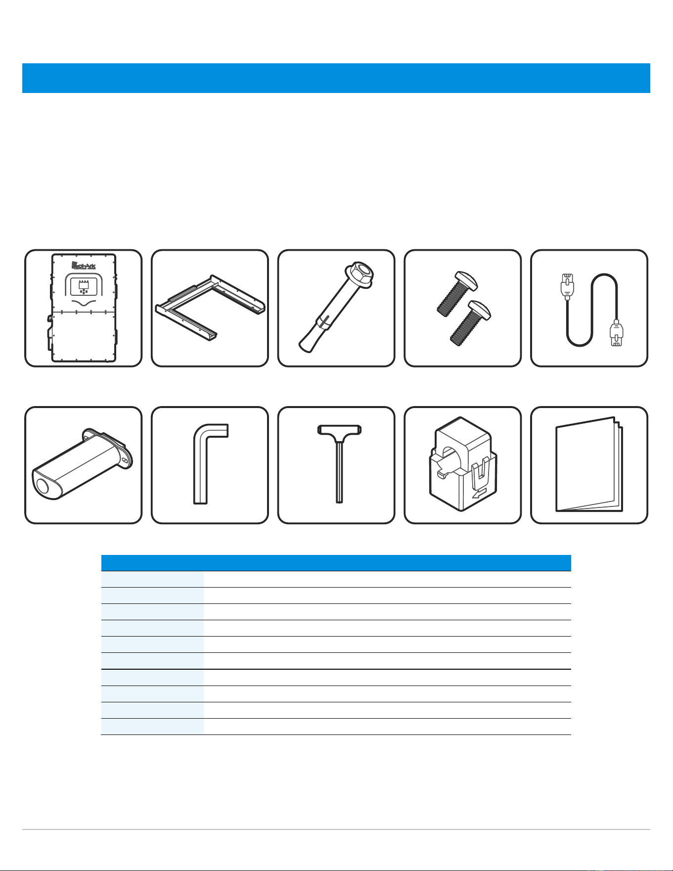
Component Guide
The Sol-Ark 60K-3P-480V system includes the following components:
Component
Description
Quantity
A
Sol-Ark 60K-3P-480V inverter
1
B
Inverter Mounting Cleat
1
C
M12x60mm expanding anchors for masonry anchoring
4
D
M4x12mm screws – Set screws for mounting carrier
9
E
Inverter Parallel Cable - CAT 5 Communication cable
1
F
Wi-Fi / Ethernet Gateway (dongle)
1
G
3mm L-type hex key for front panel screws
1
H
8mm T-type hex key for AC terminals
1
I
300A Current transformers (CT sensors)
3
J
User Manual (may not be included with all units)
1
A B C D E
F G H I J
2 Copyright © 2025 Sol-Ark LLC
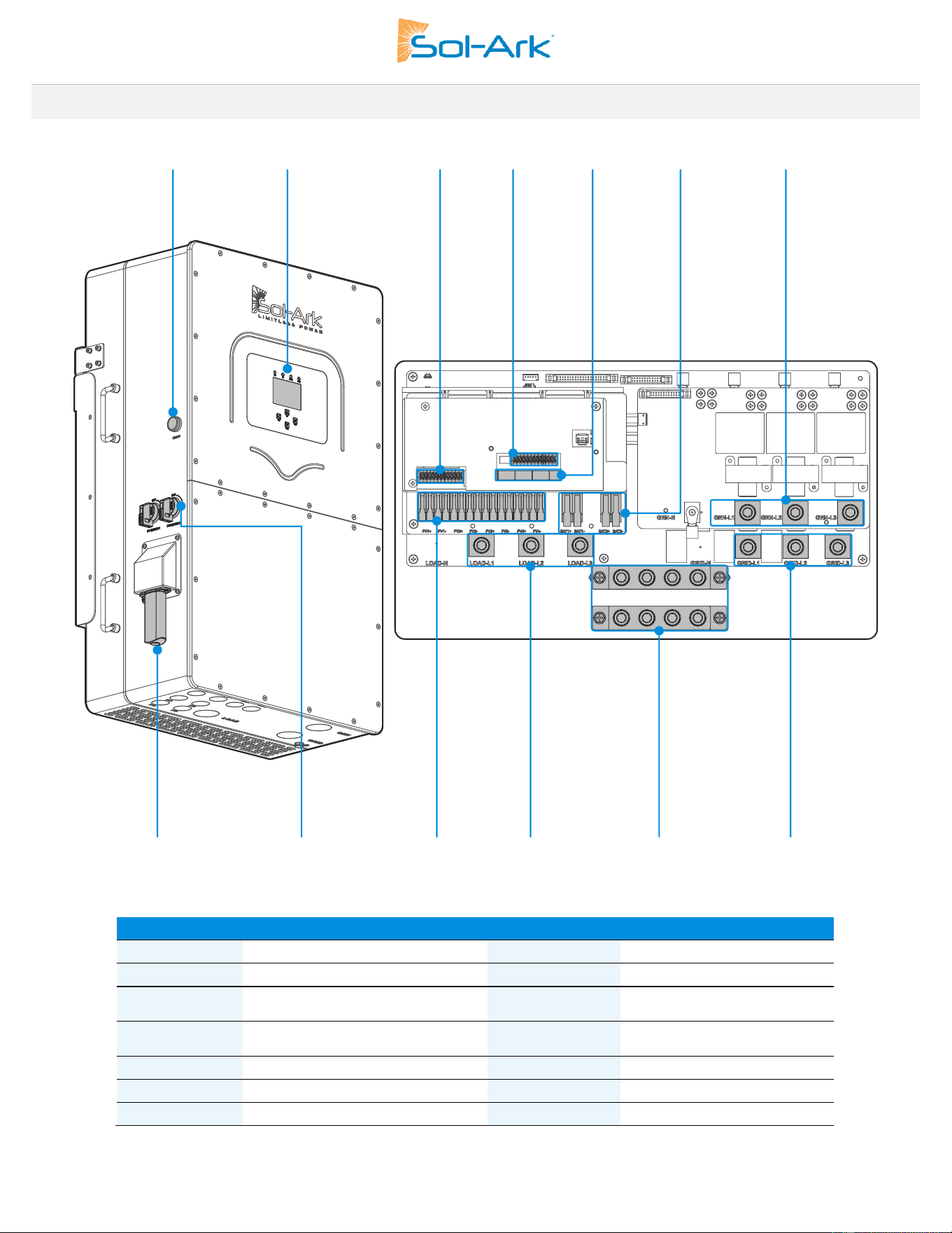
1.1 General Description
Component
Name
Component
Name
A
ON / OFF Button
H
Wi-Fi / Ethernet Gateway
B
LCD touch screen
I
2x PV DC disconnects
C
CN1 - Terminal block for sensors
and accessories
J
4x MPPT inputs terminals
D
CN2 - Terminal block for sensors
and accessories
K
(200A) LOAD terminal
E
Communication Ports
L
NEUTRAL / GROUND Busbars
F
2x (50A) Battery port
M
(200A) GRID terminal
G
(200A) GEN terminal
A
B
C
D
F
G
H
I
J
L
M
K
Sol-Ark 60K Installation Guide | SK140-0019 Rev 4 3
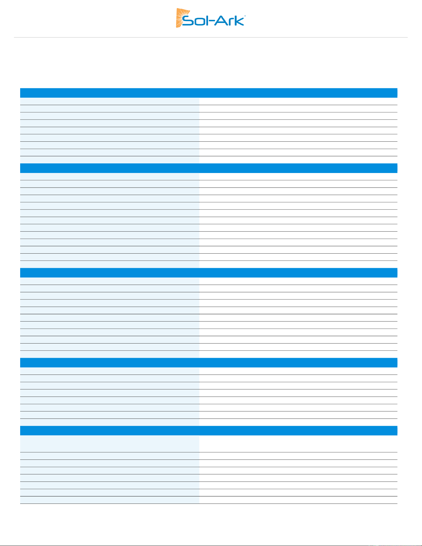
1.2 Specifications
NOTE: Temperature Derating Starts at 75°C with inverter shutdown at 82°C
SOL-ARK 60K-3P-480V FASTENER TORQUE TABLE
Do not use impact drivers to tighten any fasteners on the inverter
Terminal / Breaker
Torque [ft-lb]
Torque [Nm]
“LOAD”
18.75 ft-lb
25.5 Nm
“GRID”
18.75 ft-lb
25.5 Nm
“GEN”
18.75 ft-lb
25.5 Nm
Neutral / Ground (Busbar)
18.75 ft-lb
25.5 Nm
Cover Screws
15.5 in-lb
1.75 Nm
Battery Terminals
Push-in Cage Clamp
Push-in Cage Clamp
4 Copyright © 2025 Sol-Ark LLC
DATASHEET
60K-480V
C&I Hybrid Inverter
Inverter Model Name:
60K-3P-480V
Sol-Ark Product SKU:
60K-3P-480V
Input Data (PV)
Max. Allowed PV Power (STC)
78,000W
MPPT Voltage Range
150-850V
Startup Voltage
180V
Max. Input Voltage
1
1,000V
Max. operating input current per MPPT
36A
Max. short circuit current per MPPT
55A
No. of MPP Trackers
4
No. of PV Strings per MPPT
2
Max. AC Coupled Input
60,000W
Output Data (AC)
Nominal AC Voltage (3Φ)
277/480V
Grid Frequency
50 / 60Hz
Real Power, max continuous (3Φ)
60,000W
Max. Output Current
72.3A
Peak Apparent Power (10s, off-grid, 3Φ)
90,000VA
Max. Grid Passthrough Current (10min)
200A
Continuous Grid Passthrough Current
180A
Power Factor Output Range
+/- 0.8 adjustable
Backup Transfer Time
5ms (adjustable)
CEC Efficiency
96.5%
Max Efficiency
97.5%
Design (DC to AC)
Transformerless DC
Stackable
Up to 10 in parallel
Battery Input Data (DC)
Supported Battery Chemistry
Lithium-ion
No. of Battery Inputs
2
Battery Input Terminal Rating
50A
Nominal DC Voltage
≥ 600V
Operating Voltage Range
160 - 700V
Battery Capacity Range
50 — 9900Ah
Max. Battery Charge / Discharge Current
100A (50A per input)
Charge Controller Type
CC/CV - BMS Controlled
Grid to Battery Charging Efficiency
96.0%
Automatic Generator Start (AGS)
2 Wire Start - Integrated
BMS Communication
2
CAN (Controller Area Network)
General Data
Dimensions (H x W x D)
894 x 528 x 295 mm (35.2 x 20.8 x 11.6 in)
Weight
80 Kg / 176 lb.
Enclosure
IP65 / NEMA 3R
Operating Temperature
-40 – 60°C, >45°C Derating
Noise Level @ 1m
< 30 dB @ 25°C (77°F)
Idle Consumption - No Load
60W
Communication and Monitoring
Wi-Fi & LAN Hardware Included
Warranty
3
10 Years
Category
Certifications and Listings
(Grid Support Interactive Inverter)
UL 1741-2021 (UL1741SB), CSA C22.2 No 107.1-16,
IEEE 1547-2018 & 1547a-2020 & 1547.1-2020 (SRD V2.0),
UL 1741 CRD-PCS, UL1699B, CEC, SGIP, CSIP
PV DC Disconnect Switch — NEC 240.15
Integrated
Ground Fault Detection — NEC 690.5
Integrated
PV Rapid Shutdown Control — NEC 690.12
Integrated
PV Arc Fault Detection — NEC 690.11
Integrated
PV Input Lightning Protection
Integrated
PV String Input Reverse Polarity Protection
Integrated
Surge Protection
DC Type II / AC Type III
1. See Installation Guide for more details on sizing array strings. The highest input voltage is based on the open-circuit voltage of the array at the minimum design temperature.
2. Active BMS communication is required for all lithium batteries. A list of compatible battery partners can be found on our website.
Sol-Ark has a policy of continuous improvement and reserves the right to modify its specifications at any time and without prior notice. Please visit sol-ark.com for the latest information.
Sol-Ark 60K Installation Guide | SK140-0019 Rev 4 5
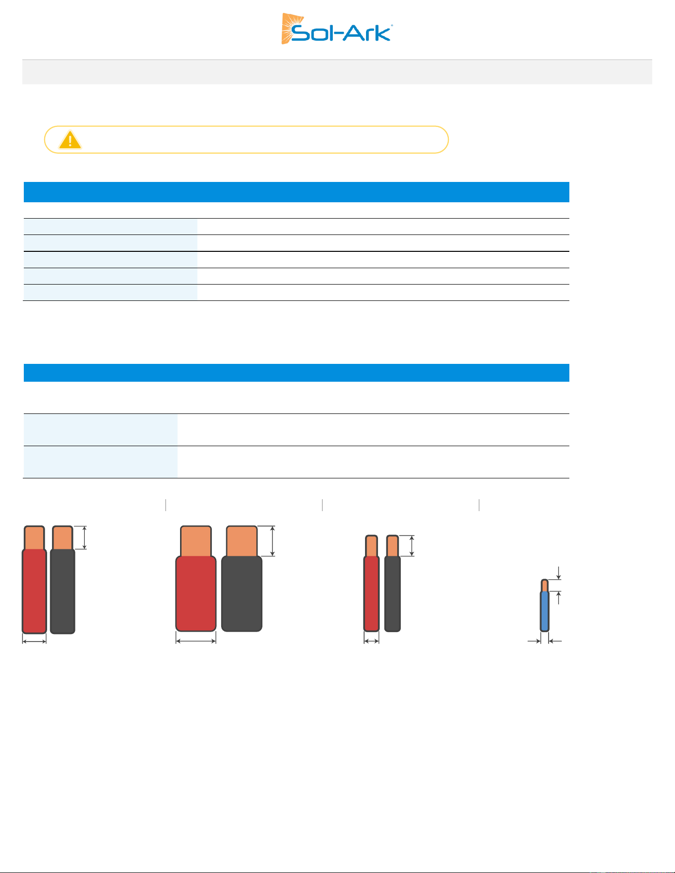
1.3 Connection Requirements
AC / DC Connection Requirements
GRID
200Aac
2AWG – 4/0 AWG
LOAD
200Aac
2AWG – 4/0 AWG
GEN
200Aac
2AWG – 4/0 AWG
MPPT
55AIsc
12 – 10 AWG
Battery Port A
50Adc
6 – 4 AWG
Battery Port B
50Adc
6 – 4 AWG
Sensors and Communications Requirements
CT Sensor
16 - 22 AWG
0’ – 10’ [3 m]: 16 AWG included
10’ – 50’ [15.3 m]: 14AWG twisted pair extension
Communications
16 – 22 AWG
0’ – 100’ [30 m]: 24 AWG
100’ – 400’ [120 m]: 23 AWG
RJ45 Parallel Communication
CAT 5E or better
0’ – 7’ [2.1 m]: Included
7’ – 20’ [6m]: Extendable
Batteries
AC Conductors
PV Conductors
Sensors
All wire runs should be sized to be at or below a 2.5% voltage drop at full load.
Equipment wire sizing must comply with the NEC or local electrical code.
Port
Max. Terminal Rating
Terminal Wire Size Range (min-max)
Component
Wire Size Range
Max Distance
0.8 in
[20.3 mm]
4/0 AWG MAX
1 in
[25.4 mm]
4 AWG MAX
10 AWG MAX
5/8 in
[16 mm]
22 AWG MAX
1/4 in
[6.35 mm]
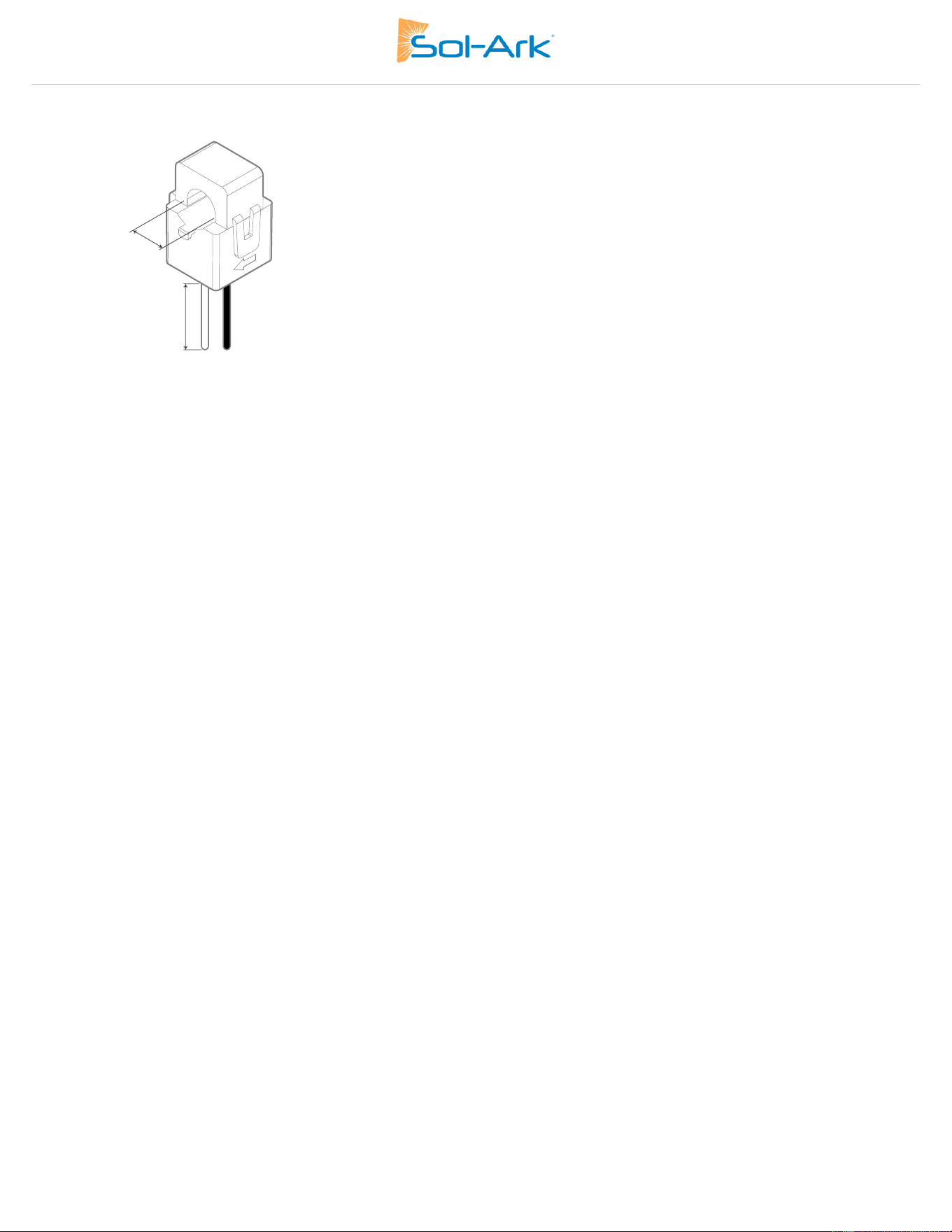
6 Copyright © 2025 Sol-Ark LLC
CT Sensors (Included)
1.85“
[47 mm]
10 ft
[3 m]
Sol-Ark 60K Installation Guide | SK140-0019 Rev 4 7
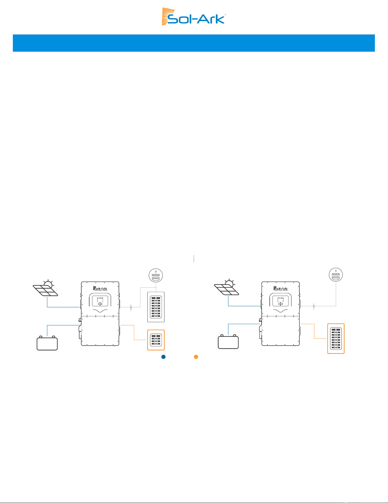
Installation
Backup Circuits
A. The “LOAD” connected service panel will be referred to as the Essential Loads Panel.
B. You must keep the essential loads panel within the limitations of the unit:
• Three phase power in a Wye configuration is calculated as follows → Real Power (W) = √3 x V
L
x I
L
x PF
• Assuming a unity power factor (PF=1) then the following represents the maximum power levels for each condition.
• Grid Tie Pass Through → 149.6kW cont. = 1.73 * 480V * 180A * 1.0
• Off-Grid → 60.1kW cont. (batteries or PV) = 1.73 x 480V x 72.3A x 1.0
C. Verify that any individual load circuit power or the aggregate rating of the whole panel does not surpass the limits listed above.
Single System Install
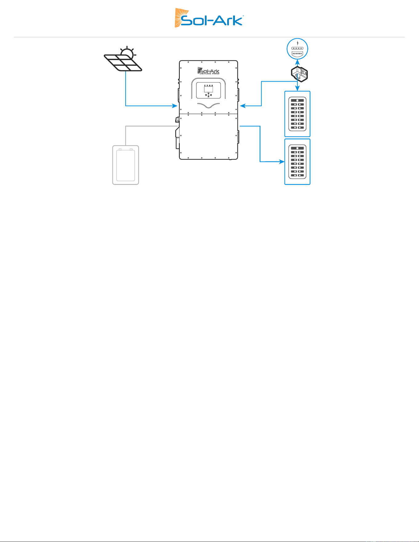
A. FOR PARTIAL BACKUP: Use a supply side connection or a load side connection with PCS as point of interconnection to integrate
the utility grid to the Sol-Ark inverter through the “GRID” terminal.
• An external service rated disconnect must be installed between the interconnection and the Sol-Ark. Size the disconnect
according to code.
• Connect the "LOAD" output to the Essential Loads Panel. Follow electric code to select proper wire gauge.
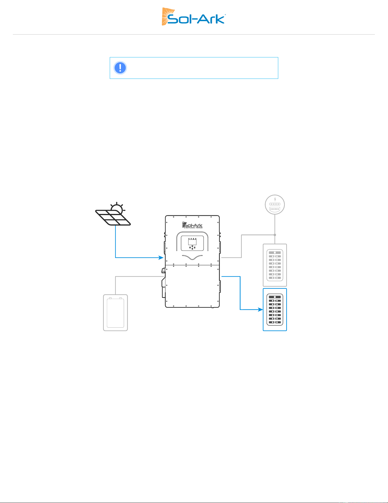
B. FOR WHOLE-SITE BACKUP: Connect the utility grid feed to the “GRID” terminal.
• An external service disconnect must be installed between the grid and the Sol-Ark. Size the disconnect according to code.
• Connect the “LOAD” output to the Main Service Panel. Follow electric code to select proper wire gauge.
It’s possible to connect a generator, or an AC coupled source such as grid-tie string or micro inverters, to the “GEN” terminal of the
inverter. Only one AC source can be connected to the “GEN” terminal at a time.
Partial Backup
Whole-Site Backup
AC
DC
PV
Battery
Grid
Main Panel
Subpanel
PV
Battery
Grid
Main Panel
8 Copyright © 2025 Sol-Ark LLC
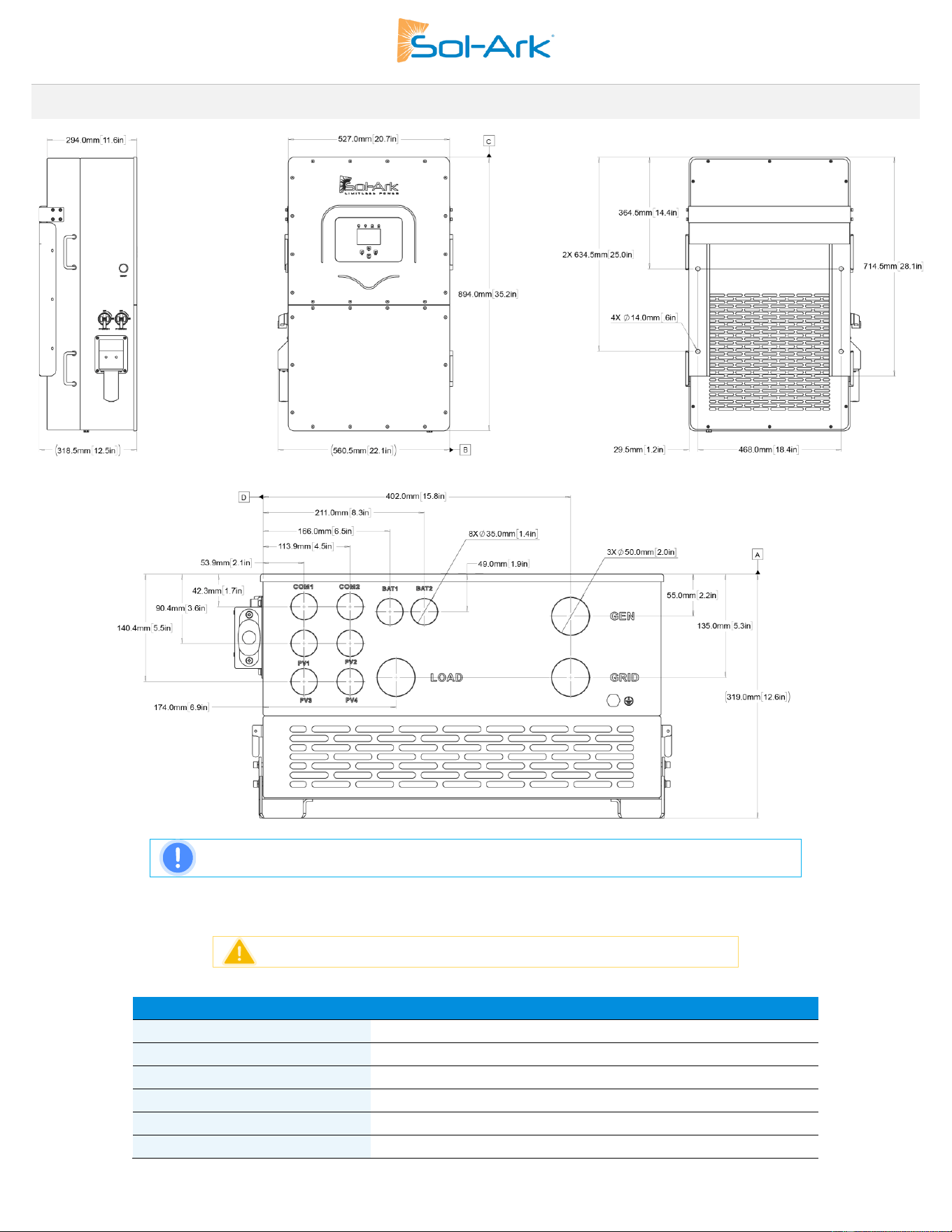
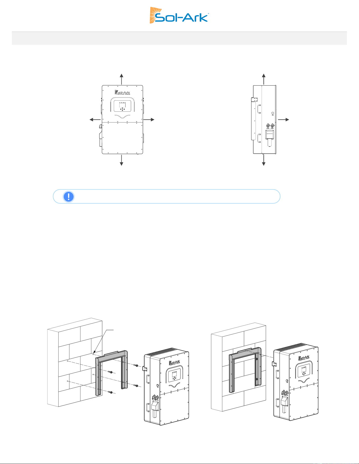
2.1 Mounting the Inverter
Considering the dimensions of the inverter, find a suitable location for the system. There must be at least 6 in [15 cm] of vertical clearance
and 2 in [5 cm] of side clearance for proper heat dissipation.
Figure 1: Inverter Clearances Overview
NOTE: Inverter has a Maximum Heat Dissipation of 2,100W or 7,165BTU/hour
• Under certain conditions, the National Electrical Code® specifies greater clearances. Be sure to adhere to the clearances listed in
the National Electrical Code®, paragraph 110.26 and Canadian Electrical Code® CSA C22.1.
• The Sol-Ark 60K-3P-480V is a NEMA 3R - IP65 enclosure rated for outdoor installation, but it can also be installed indoors.
• Use screws or anchors suitable for the support surface and capable of supporting the weight of the inverter (176 lb / 80kg).
a. For Concrete or Masonry Mounting: Use a minimum of four M12x60mm expanding anchors (included).
b. For Wood Frame Mounting: Use a minimum of four ½-in lag screws with flat washers (not included), making sure to anchor
into at least 2 framing members.
c. For Metal Framing Mounting: Use a minimum of four ¼-in self-tapping metal screws with flat washers (not included).
• If you need a different anchorage, calculate the number of anchor points needed to properly hold the weight of the
equipment.
• Secure the inverter to the French Cleat with six of the provided M4x12mm socket head screws.
Figure 2: Inverter Mounting Diagram
≥ 6” [15 cm]
≥ 6”[15 cm]
≥ 2” min [5 cm]
6” if next to
another system
≥ 2” min [5 cm]
6” if next to
another system
≥ 20” [50 cm]
≥ 6” [15 cm]
≥ 6”[15 cm]
Suitable anchor for
the wall surface
Sol-Ark 60K Installation Guide | SK140-0019 Rev 4 9
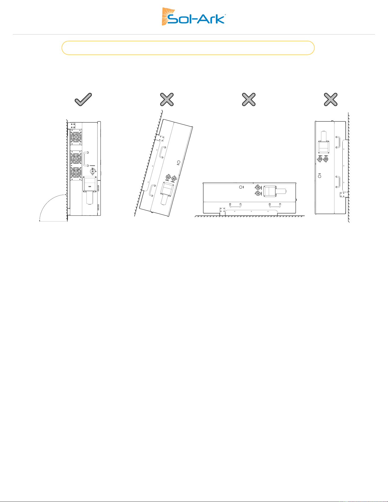
Damage to the LCD Screen due to direct sunlight exposure will not be covered by warranty.
• Mount the inverter in the optimal orientation as shown below.
Figure 3: Inverter Mounting Orientation
10 Copyright © 2025 Sol-Ark LLC
2.2 Integrating Batteries
A. Sol-Ark 60K-3P-480V must be OFF while you connect the batteries.
B. Be sure that the external battery disconnect is OFF or arcing may occur. If your battery bank does not have a built-in disconnect,
maintain the necessary safety measures when handling the connections.
C. The 60K-3P-480V reaches a max battery charge/discharge of 50A per terminal for a total max of 100A if using both sets of battery
terminals. If only one set of terminals is used, the battery charge/discharge will be limited to 50A.
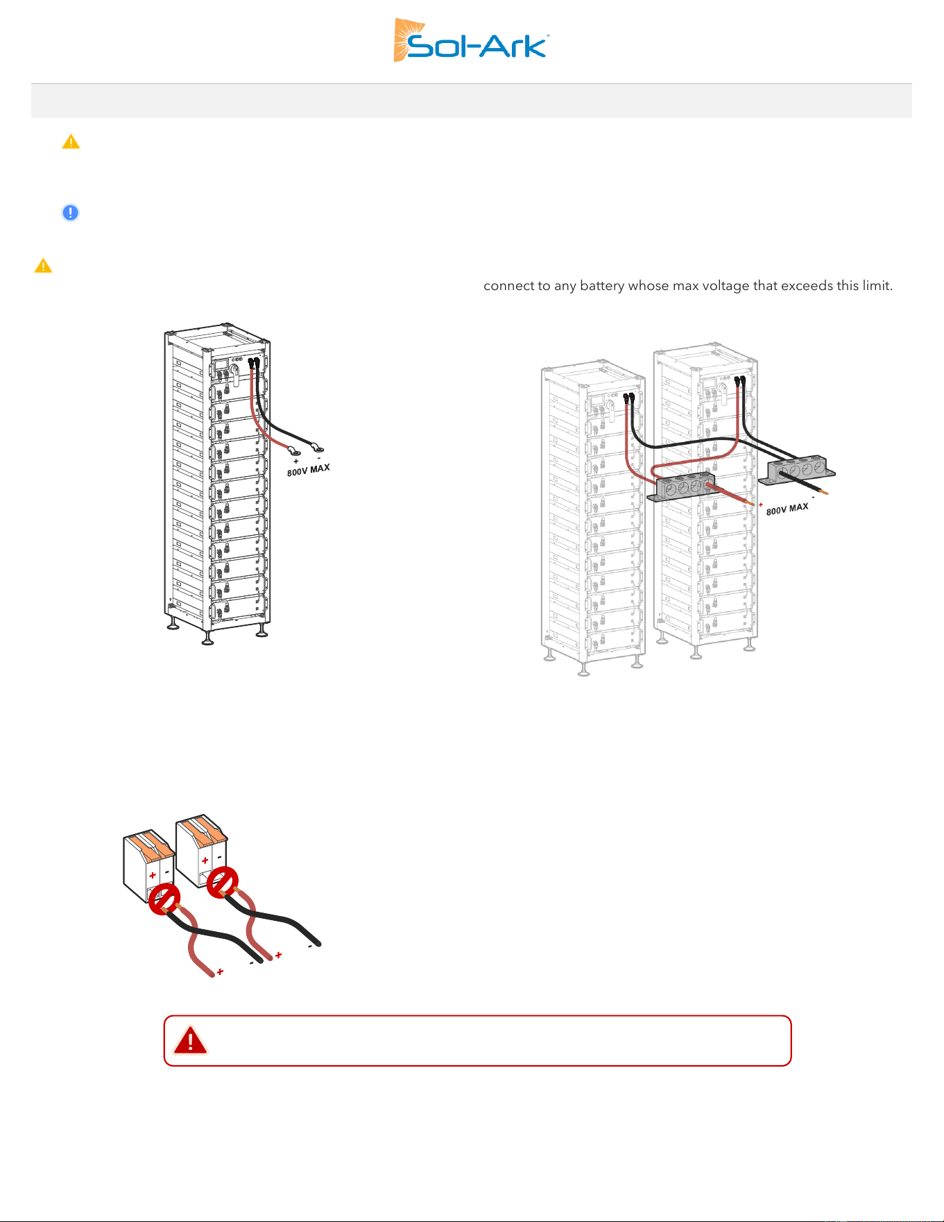
Sol-Ark 60K-3P-480V is a HIGH VOLTAGE BATTERY system. You MUST NOT exceed 800V
DC
as shown below. The HV battery must
stay within the 160V
DC
- 700V
DC
operating voltage range. DO NOT connect to any battery whose max voltage that exceeds this limit.
a) Single HV battery
b) Bank of multiple HV batteries
Figure 4: Battey Wiring Output
The Sol-Ark inverter has two input battery terminals for single or dual battery connections. To wire a battery to the inverter, lift the actuation
levers and insert the 6-4 AWG battery conductor fully into the terminal. DO NOT force open the battery actuation levers more than 90°.
DANGER: Reverse Polarity
DO NOT reverse the battery input wires, the system will be damaged, and the warranty voided.
Sol-Ark 60K Installation Guide | SK140-0019 Rev 4 11
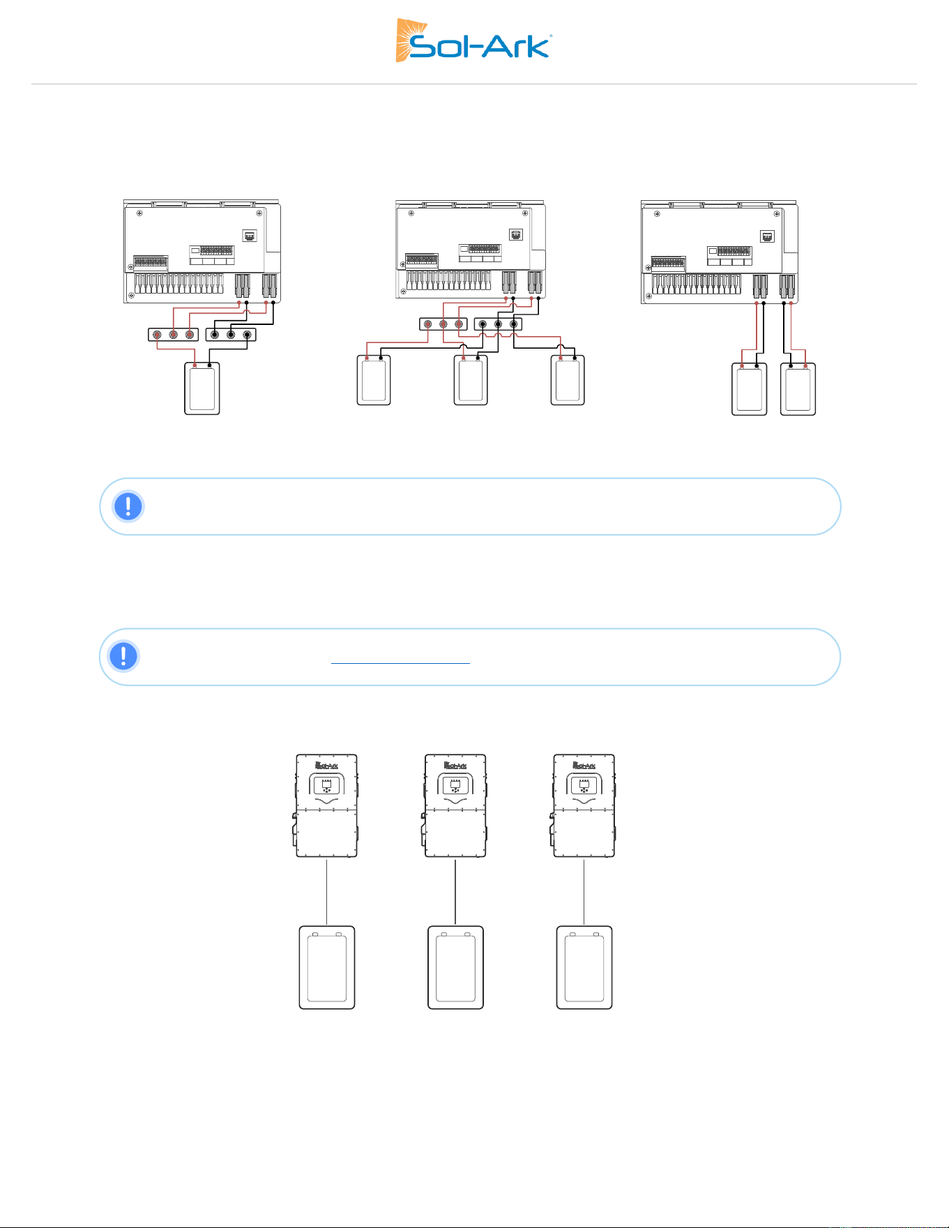
Multi-Terminal Installation
The two battery input terminals of the 60K-3P-480V can be configured for parallel battery stacks in settings screens. If the charge/discharge
rate of 100A is needed, the battery must be connected to both input terminals. If connecting more than one battery to a single inverter
input terminal, you must use an external busbar or combiner to combine batteries positive and negative outputs before connecting to the
inverter terminals.
a. Single battery
B. Parallel battery bank
c. Dual battery bank
NOTE: If a single battery is capable of charge/discharge currents above 50A, connect the battery to both
input terminals. Otherwise, the charge and discharge rate will be limited to 50A max. Only connect
batteries of the same model to the terminals
Parallelled Battery Installations
A. ALL systems MUST be connected to their own battery bank, and the battery banks must be the same size.
B. DO NOT parallel batteries between inverters.
Figure 5: Inverter to Battery Ratio Diagram
NOTE: Multi-Inverter Installations
Please contact Sol-Ark at: [email protected] or +1 (972) 575-8875, Ex. 2 for help with commissioning
multiple parallelled inverters.
12 Copyright © 2025 Sol-Ark LLC
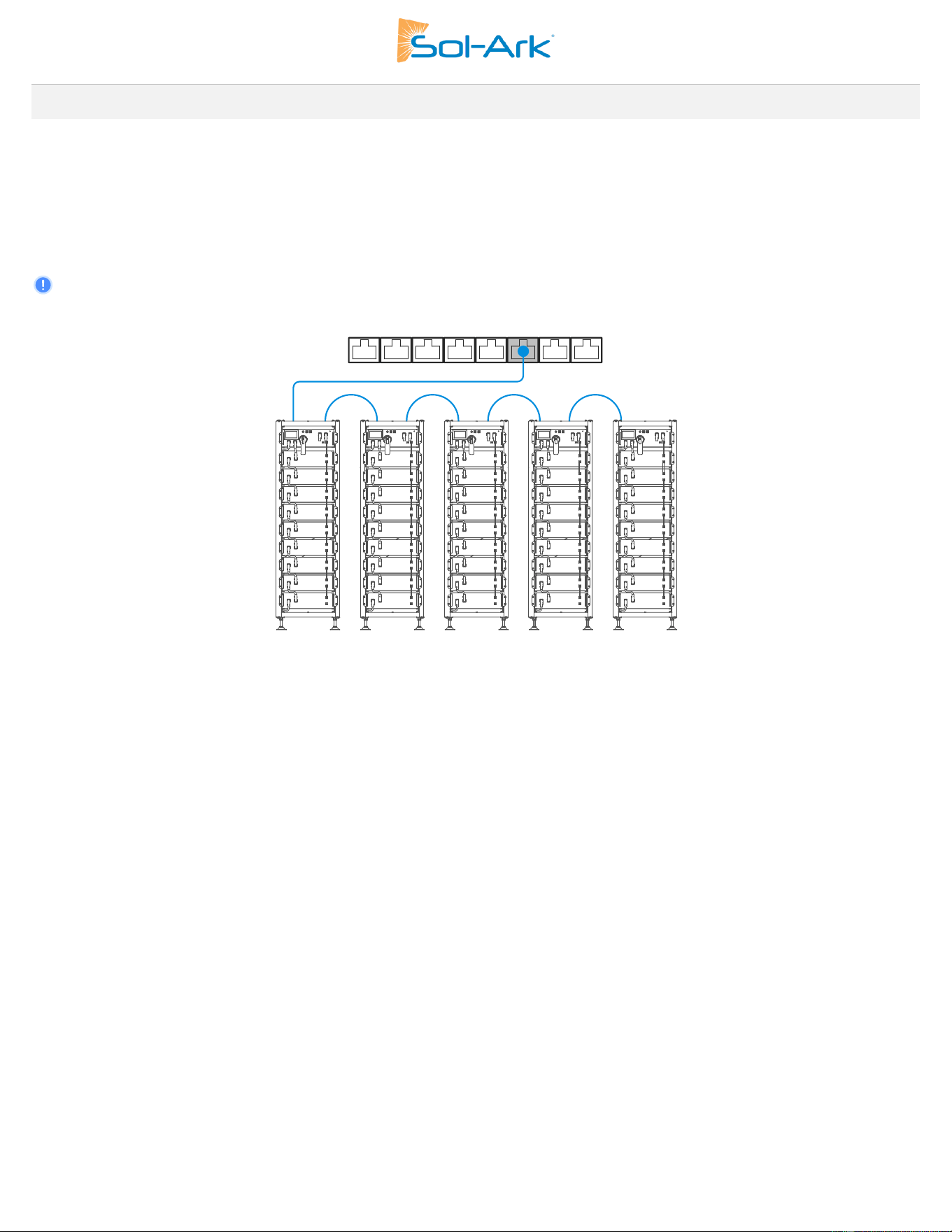
2.3 Battery Communications
The Sol-Ark 60K-3P-480V inverter can establish closed-loop battery communication through one or two separate RJ-45 ports labeled
“BMS1” and “BMS2”. Communication with battery BMS will depend on the wiring of the battery bank and the wiring to the Sol-Ark inverter.
The following two methods show how communications can be established:
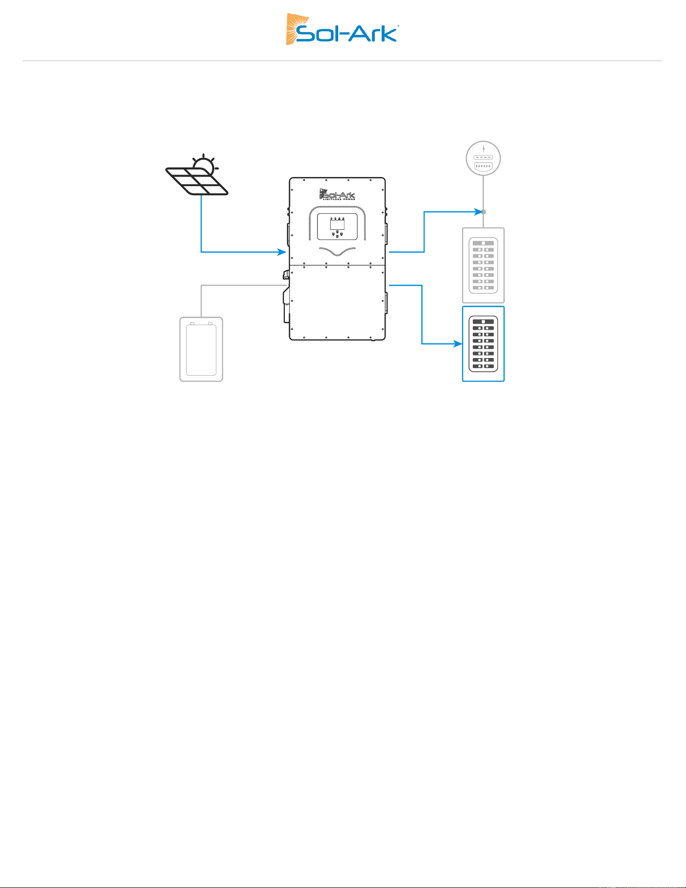
Single Battery Bank Communication
Configure and wire the HV batteries so that there is one battery bank with a single communication source. Closed-loop communication is
established by connecting the com cable to the “BMS1” port of the Sol-Ark inverter.
“🗹 Parallel Bat1&Bat2” setting on the Batt setup menu MUST be enabled and batteries must be connected in parallel on the DC side.
See previous section “Multi-Terminal Installation” for detailed wiring of multi-terminal, single battery bank installation.
Figure 6: Single battery bank communication
Parallel bat1&bat2: Must be checked when using both battery inputs for the same battery bank. When enabled, the inverter will expect a
single battery communication source.
Sol-Ark 60K Installation Guide | SK140-0019 Rev 4 13
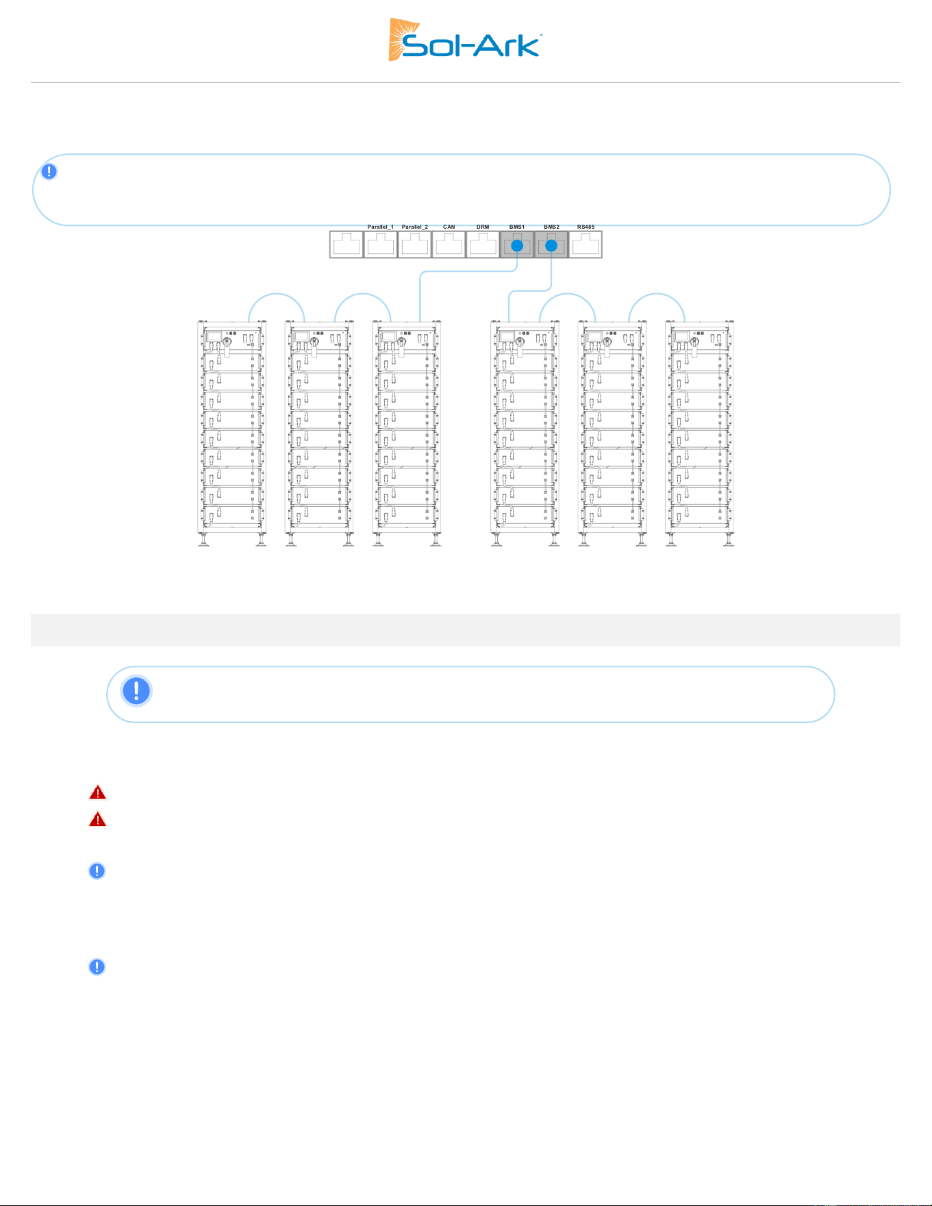
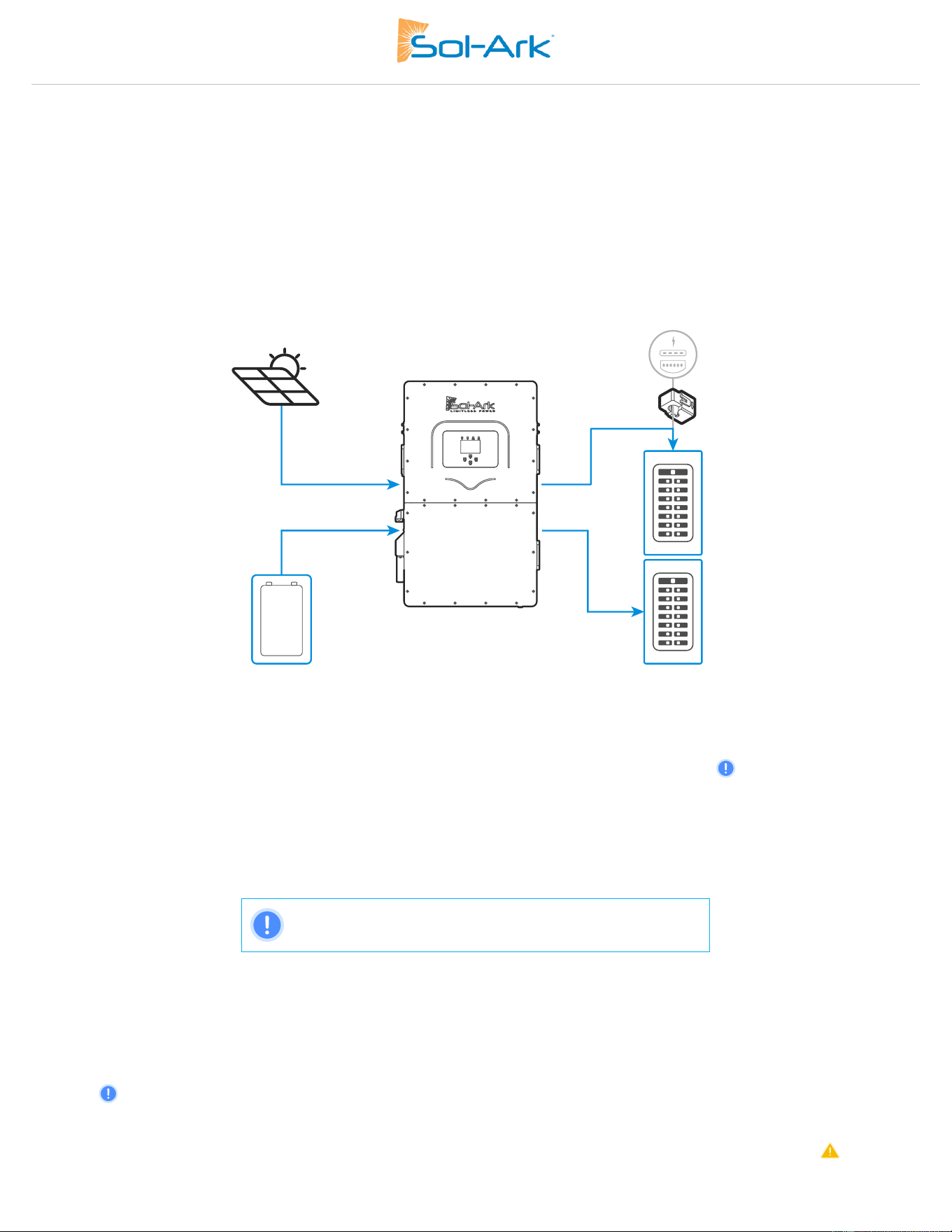
Separate Battery Banks Communications
Configure and wire the HV batteries so that there are two battery banks, each with their separate communication source. Closed-loop
communications are established by connecting each communication cable to a BMS port of the Sol-Ark (“BMS1” and “BMS2”).
“Parallel Bat1&Bat2” setting on the Batt setup menu SHOULD NOT be enabled, the dual battery bank wiring configuration shown
earlier MUST be carried out. See previous section “Multi-Terminal Installation” for detailed wiring of parallel battery bank and dual
battery bank installation.
Figure 7: Multi-Battery Bank Communications
2.4 Connecting Solar PV to the Inverter
A. Max DC solar input = 78 kW (± 5%) | Max input power per MPPT = 19.5 kW | Max recommended input voltage per MPPT = 850
V
OC
| Max input current per MPPT = 36A (self-limiting).
B. Design for an input current of 36A per MPPT. The inverter will self-limit beyond 36A. If I
SC
exceeds 55A, damage will occur.
C. PV Source Circuit max voltage of 1,000V
OC
D. Damage can occur with PV strings whose open-circuit voltage exceeds 1,000V
OC
E. Strings in parallel on the same MPPT must have the same designed open-circuit voltage (Voc), otherwise the system will be
limited to the lowest string voltage.
• PV1 A/B must have the same Voc.
• If the solar panels are oriented in different directions and connected in the same MPPT, there will be a loss in PV efficiency.
F. Per NEC Art 690.43, exposed non-current-carrying metal parts of PV module frames, electrical equipment, and conductor
enclosures of PV systems shall be connected to an equipment grounding conductor. All grounding conductors and grounding
electrodes should be installed according to NEC Art 690.47 or as required by the AHJ.
G. For ground mounted arrays, Sol-Ark recommends installing an auxiliary grounding electrode placed near the array to ensure
optimal earth-to-ground resistance of the grounding system. This auxiliary electrode would need to follow the requirements of
NEC Art. 250.54.
NOTE: 60K-3P-480V has 4 independent MPPTs that support up to 2 PV strings each. The MPPTs can
handle a maximum V
OC
of 1,000V and an I
SC
of 55A but will self-limit and operate at I
mp
of 36A max.
14 Copyright © 2025 Sol-Ark LLC
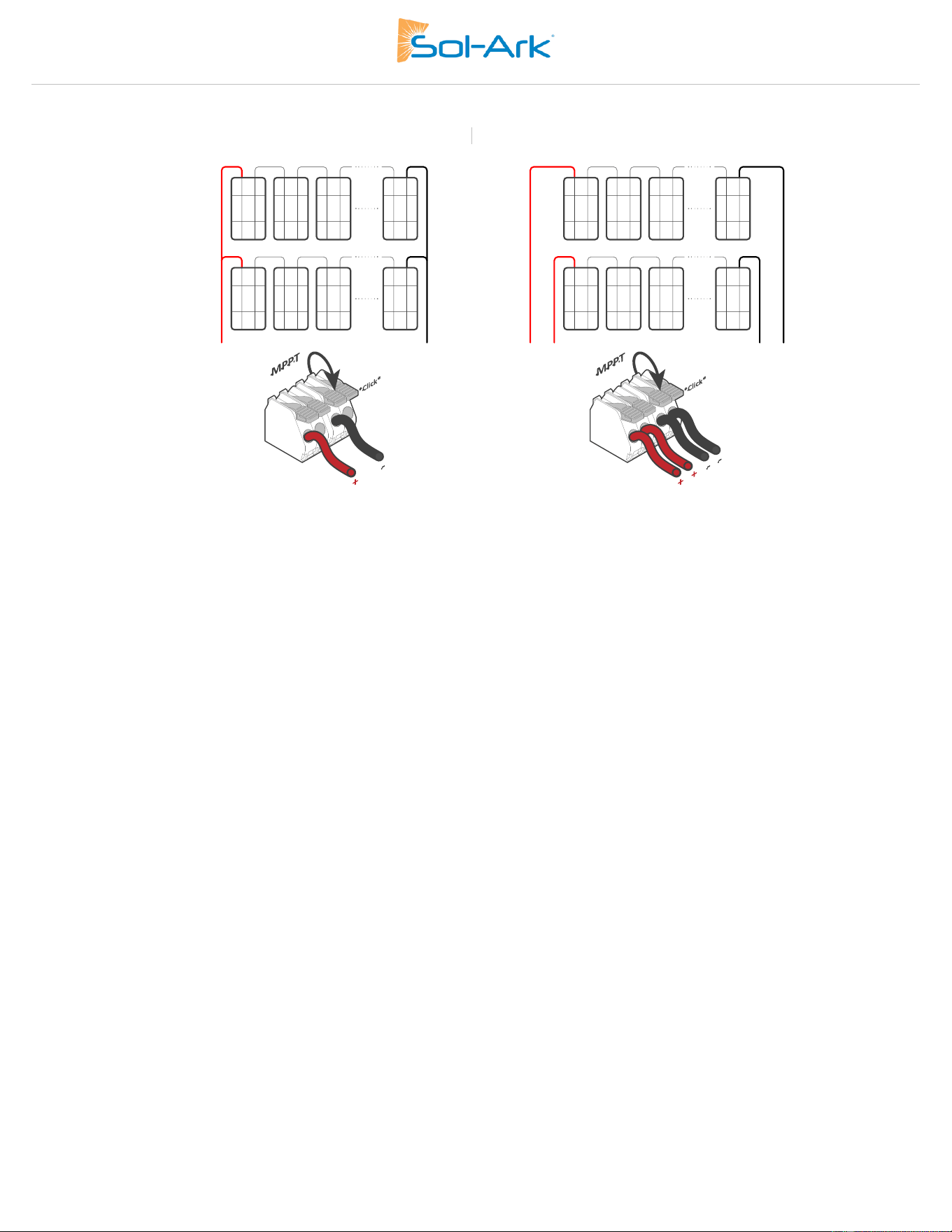
H. Connect the solar panel strings using either of the following configurations:
“Y” connection or PV Combiner
Individual strings
String PV1B
String PV1A
String PV1B
Y Connector
Y Connector
String PV1A
Sol-Ark 60K Installation Guide | SK140-0019 Rev 4 15
AC Coupling
The Sol-Ark 60K-3P-480V supports the addition of grid-tied solar inverters, this allows the systems total solar power input to be expanded
by coupling 3Φ micro or string inverters into the “GEN” terminals of the inverter.
An entirely AC-coupled solar system is not recommended as power control and monitoring is limited but is supported. Having DC-coupled
modules, or a combination of DC-coupled modules and AC-coupled inverters is always preferred. AC-coupled inverters used in this
application need to be either UL 1741SA or SB certified. This certification confirms the inverters’ ability to disconnect from the grid based
on frequency and ensures that the Sol-Ark will safely be able to frequency shift to control the AC coupled production.
In off-grid systems or during grid-forming operation, the 60K-3P-480V uses frequency shifting to curtail and shutdown AC-coupled
inverters when the battery is full, allowing AC-coupled solar to produce power in an outage scenario. When the 60K-3P-480V is connected
to the grid any AC-coupled inverters connected will always sell all excess solar power back to the grid. Selecting “Limited to Load” will
NOT limit production when AC coupled.
Maximum allowed AC coupling input: 60,000W
AC
AC Coupling on the GRID Side
Installing AC coupled inverters upstream of the GRID port of the 60K-3P-480V, such as with a load or supply side connection, is supported
for grid connected systems but has some notable limitations when using the inverter for backup or grid-forming mode:
• Does NOT allow the usage of grid-tied inverter production during grid outages to charge batteries or power loads.
• Does NOT allow monitoring of PV production in inverter and MySolArk monitoring.
AC Coupling on the GEN Terminal
AC Coupling via the GEN Terminal is the preferred method for integrating AC-coupled solar on the 60K-3P-480V. This method offers
several key advantages:
• Allows the usage of grid-tied inverter production during grid outages.
• Allows the integration of grid-tie inverters in off-grid systems.
Using the GEN terminal also allows for comprehensive monitoring of solar production, giving users valuable insights into the system's
performance. See Section 3.4 - AC Coupling Settings for details on programming the 60K-3P-480V for this mode of operation.
AC Coupling on the LOAD Terminal
NOTICE: Sol-Ark does not support AC-coupling on the LOAD terminal with the 60K-3P-480V.
16 Copyright © 2025 Sol-Ark LLC
2.5 Integrating a Generator
Generators Smaller than 149kW → On “GEN” Input
1. ONLY supports three-phase 480Vac generators.
2. 200A rated “GEN” terminal. 180A continuous.
3. A THD (Total Harmonic Distortion) of less than 15% is required for stable operation.
Generators Greater than 149kW → On “GRID” Input
1. ONLY supports three-phase 480Vac generators.
2. Optimal way to integrate generators for Off-Grid or Grid-Tied systems with automatic or manual transfer switches.
3. Programming “GEN Connect to Grid Input” is required: → Limiter → Other →
🗹
GEN Connect to Grid Input.
4. DO NOT use “Grid Sell” when generator is connected to the GRID input, can cause potential damage the generator.
Installation of CT sensors on generator lines is only required if “Peak Shaving” is intended to be used.
Improve the Generator & Sol-Ark Compatibility
Navigate to Settings → Grid Setup → Grid Selection → Grid Mode and program the following values to improve the Sol-Ark and generator
compatibility and operating range to avoid frequent disconnections.
1. Change the grid mode to General Standard: → Grid Setup → Grid Selection → Grid Mode.
a. Tap and use the navigation arrows to cycle through the different grid modes. Choose “General Standard”.
2. Increase the frequency range of operation: → Grid Setup → Connect → Reconnect
a. Increase “Grid Hz High” to 65Hz.
b. Decrease “Grid Hz Low” to 55Hz.
c. Replicate changes for the “Normal Connect” settings.
3. Increase the voltage range of operation:
a. Increase “Grid Volt High” to 528V.
b. Decrease “Grid Volt Low” to 432V.
c. Replicate changes for the “Normal Connect” settings.
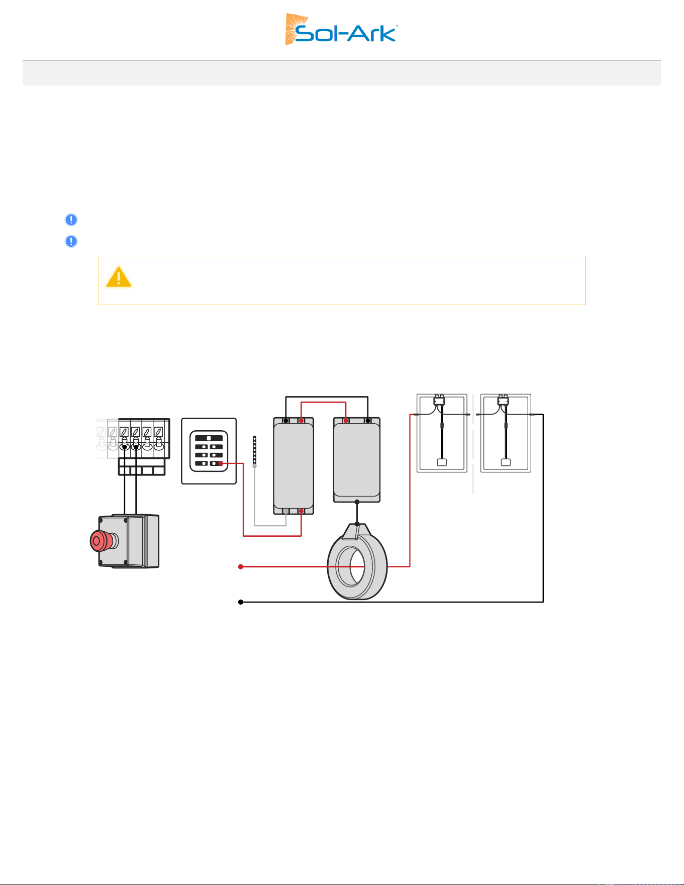
2.6 Grid Peak Shaving
1. To use Peak-Shaving on a generator, the equipment MUST be connected to the
“GRID” terminal of the inverter.
2. Peak-Shaving helps reduce grid consumption during peak demand by utilizing battery
backup power. It can also be used to prevent generator overload above a specified
power threshold.
3. Install the CT sensors on grid / generator lines L1, L2, L3. The arrows on the CTs MUST
point toward the inverter.
4. The Sol-Ark supplies power from the batteries whenever the “Power” threshold is met.
5. This mode will automatically adjust the “Grid Charge” amperage (A) to avoid
generator overloads during battery charging.
6. Grid Peak-Shaving will automatically enable “Time of Use” and MUST be configured.
Grid peak-
shaving
Generator and grid
charge settings
Sol-Ark 60K Installation Guide | SK140-0019 Rev 4 17
2.7 Automatic Generator Start
1. “ 🗹 Gen Charge” is used when the generator is connected to the “GEN” terminal.
a. “Start V” or “Start %” is the set-point/condition that must be fulfilled to automatically start the generator.
b. To charge from the “GEN” source, “🗹 Gen Charge” must be enabled.
c. Batteries will charge from a generator until the battery bank accepts 5% of its programmed capacity in Amperes (A). This
is equivalent to around 95% of the state of charge (SOC).
2. “🗹 Grid Charge” is used to charge the battery from the “GRID” source (grid or a generator).
a. “Start V” or “Start %” is the set-point/condition that must be fulfilled to start the battery charge from the “GRID” source. This
will auto-start a generator as well.
b. To charge the battery from the “GRID” source, “🗹 Grid Charge” must be selected: → Battery Setup → Charge.
c. From utility grid: the batteries will be charged to 100% SOC.
d. From generator: the batteries will charge until the battery bank accepts 5% of its rated capacity in Amperes (A). This is
equivalent to around 95% SOC.
Gen Charge / Grid Charge “A”
“A” is how many amps (DC) are supplied to the battery from the “GRID” or “GEN” source. Adjusting and limiting the Gen or Grid “A” value
will ensure that small generators are not overloaded when charging the battery bank.
If connecting more than one HV battery in parallel to the Sol-Ark inverter, divide the Gen or Grid “A” value by the # of batteries to estimate
the current (A) flowing to each HV battery.
NOTE: If “Time of Use” (TOU) is enabled, a time to charge from that GRID or GEN source MUST be
designated. “🗹 Charge” must be checked on desired time intervals, otherwise the generator will not
start automatically even if the Start V or Start % condition has been met.
18 Copyright © 2025 Sol-Ark LLC
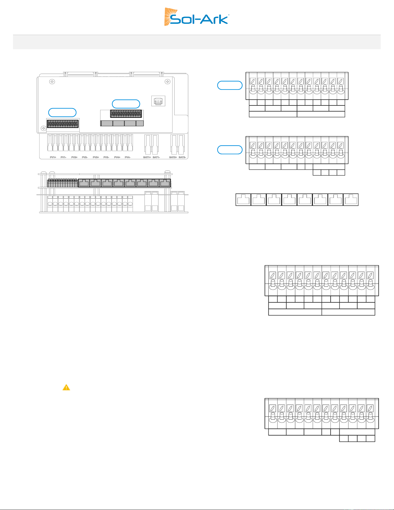
2.8 Integrating Sensors and Accessories
Figure 8: Overview of Inverter Pinouts
Figure 9: Inverter Terminal Blocks
Sensor Pin Out (Located in Sol-Ark user area)
CN1:
Max. 5A Secondary CTs ONLY:
• (1,2) 5A to 1A Input - CT-R: Current transformer (L1). Polarity sensitive.
• (3,4) 5A to 1A Input - CT-S: Current transformer (L2). Polarity sensitive.
• (5,6) 5A to 1A Input - CT-T: Current transformer (L3). Polarity sensitive.
Max. 50mA Secondary CTs ONLY:
• (7,8) 10mA to 50mA Input - CT-R: Current transformer (L1). Polarity sensitive.
• 9,10) 10mA to 50mA Input - CT-S: Current transformer (L2). Polarity sensitive.
• (11,12) 10mA to 50mA Input - CT-T: Current transformer. (L3). Polarity sensitive.
CN2:
• (1,2) G-Start: Normally Open (NO) relay for generator two-wire start
o ( 12V, 100mA max)
• (3,4) Dry-1 and (5,6) Dry-2: Reserved
• (7,8) RSD+/-: Reserved, DO NOT CONNECT ANY RSD TRANSMITTER
• (9,10) Emergency Stop Button: Normally Open (NO) dry contact for emergency
stop button
• (11, 12) +/- : Reserved, not used at this time.
CN1
CN2
CN1
CN2
Figure 11: CN2 Pinout
Figure 10: CT Sensor Input Pinout
Sol-Ark 60K Installation Guide | SK140-0019 Rev 4 19
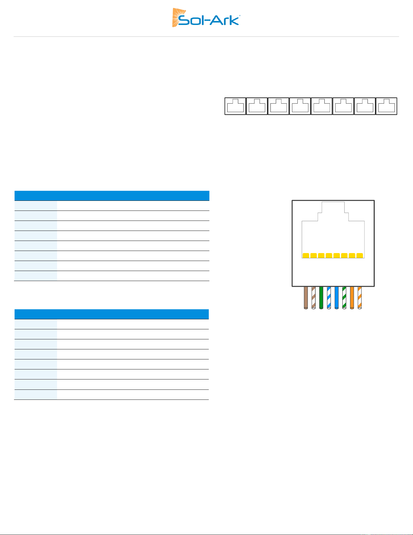
Communication Ports
• Meter: For external Revenue Grade energy meter communication.
• Parallel_1 & Parallel_2: Inverter parallel communications ports 1 and 2.
• CAN: Reserved.
• DRM: Reserved.
• RS-485: RS-485 port
• BMS1 & BMS2: BMS ports 1 and 2 for battery communications
CAN & RS485 Ports
• CAN port data is in a proprietary format. Sol-Ark currently does not support third-party usage.
• The RS485/RTU port utilizes the MODBUS protocol, data is in a proprietary format. Please contact Sol-Ark to request the MODBUS
register map if it is required for your application.
BMS Communication Ports
Pin
RS485
CAN
1
B-
B-
2
A+
A+
3
--
--
4
--
CAN High
5
--
CAN Low
6
GND
GND
7
A+
A+
8
B-
B-
Pin
BMS1
BMS2
1
--
--
2
--
--
3
--
--
4
CAN High
CAN High
5
CAN Low
CAN Low
6
GND
GND
7
--
--
8
--
--
8 7 6 5 4 3 2 1
Figure 12: Communication Ports
20 Copyright © 2025 Sol-Ark LLC
GEN Start Signal (Two-wire start)
• Gen start relay: CN2, pins 1 & 2.
• The signal comes from a normally open relay that closes when the generator Start condition is met.
Wi-Fi / Ethernet Antenna (Dongle)
• Remote monitoring and software updates require an internet connection through the Wi-Fi / Ethernet Gateway (Dongle).
• Supports with 2.4GHz Wi-Fi or Ethernet connections.
Figure 13: WiFi Gateway
Sol-Ark 60K Installation Guide | SK140-0019 Rev 4 21
2.9 Connecting Current Transformers (CT Sensors)
The CT sensors (or limit sensors) enhance system capabilities by enabling the use of the system work modes known as “Limited Power to
Home” (Meter Zero) and “Grid Peak-Shaving”. The CTs will measure and calculate total load demand which the Sol-Ark 60K-3P-480V will
then use to accurately supply and offset all existing loads (Meter Zero).
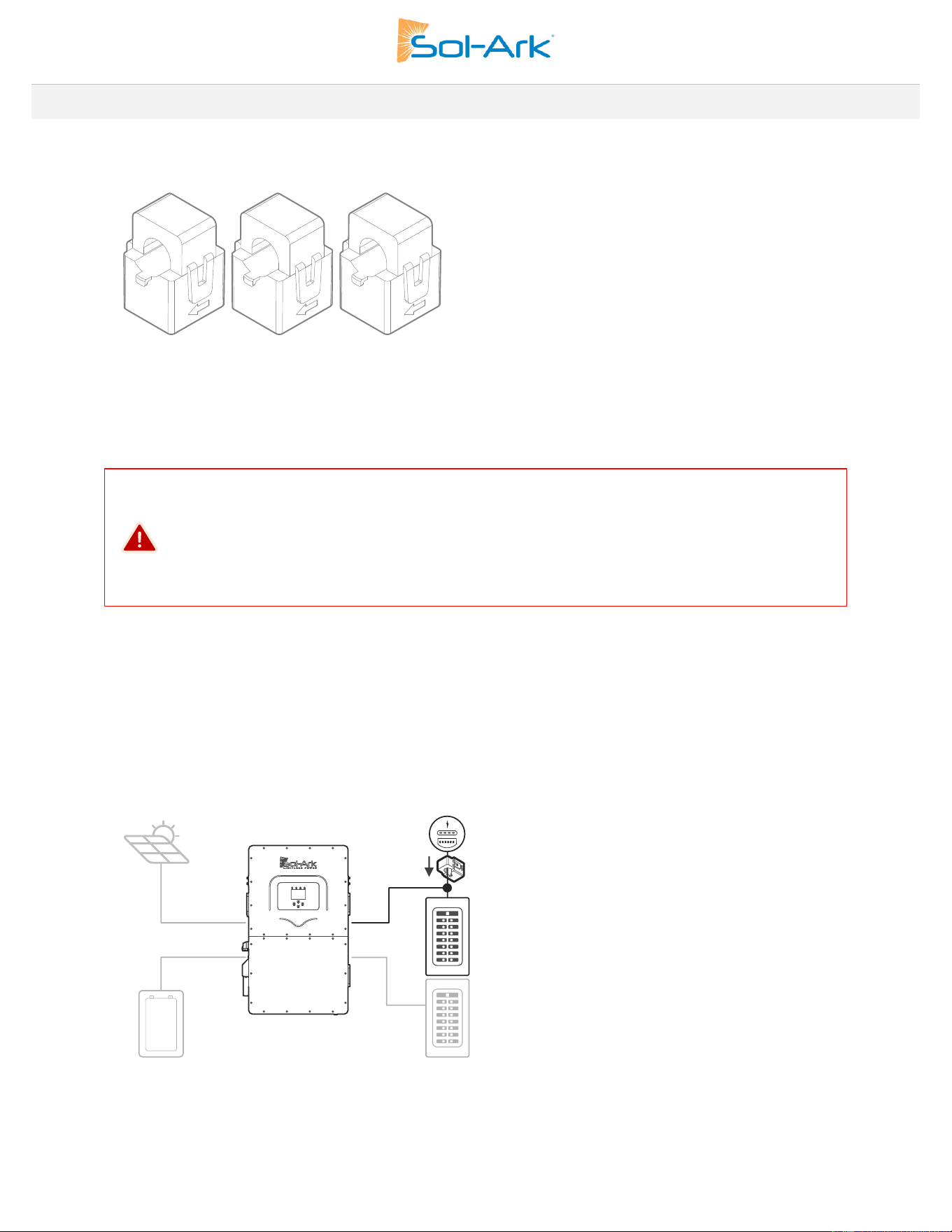
Figure 14: CT Sensors
1. Installing CT Sensors
DANGER: RISK OF ELECTRIC SHOCK
Before installing CT sensors around current-carrying conductors, you MUST:
1. Connect the CT outputs to the designated inverter input terminals, OR
2. Short the CT output wires using a CT shorting block
This step is crucial to prevent the generation of dangerously high voltages in the CT secondary
winding when this circuit is open and current is flowing through the primary.
• To begin, install sensors on incoming electrical service wires (L1, L2, L3).
• The marked arrows on the CT sensors must point towards the inverter.
• To ensure proper fit, check incoming wire diameters (grid or generator). If the sensors are too small, larger CTs can be purchased.
• “Limited Power to Home” (Meter Zero) and “Grid Peak Shaving” require CT sensors.
• See section 3.5, “Limiter” for more information about the different work modes.
• See section 7, “Wiring diagrams” for more information on CT installation.
Figure 15 Overview of CT Placement
2. CT Sensor Size
• The 60K-3P-480V inverter includes three 300A CT sensors with a 1.85x2” (47x52mm) opening.
• The inverter should be programmed to use a ratio of 6000:1 if using the included 300A CT’s.
• For sites with services larger than 300A see Section 4. Selecting Current Transformers for Larger Services
CTs
Meter
Main Panel
Line Side Tap
Subpanel
22 Copyright © 2025 Sol-Ark LLC
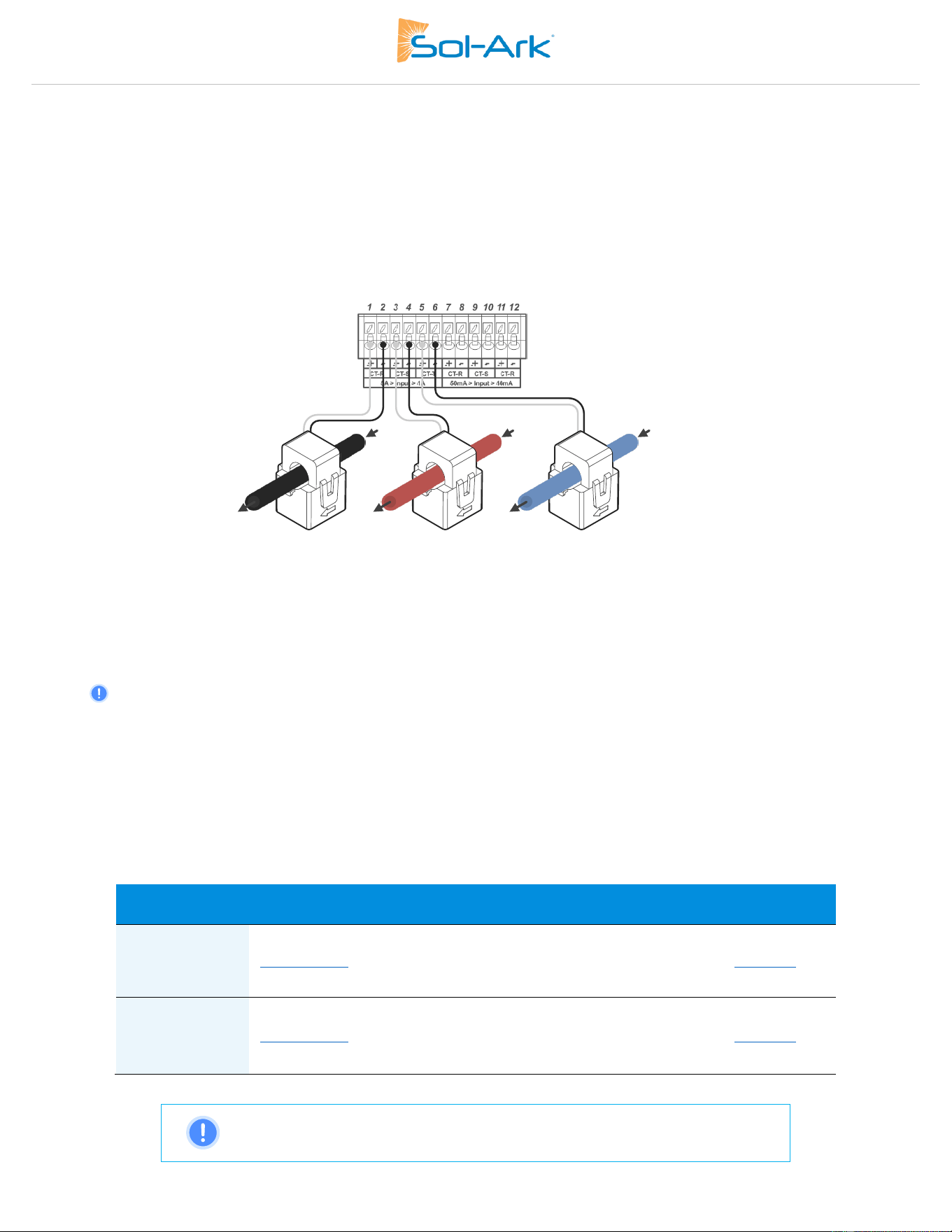
3. Wiring the CT sensors
• Connect CT1 of line L1 to pins 1+ (white) & 2- (black) of CN1 pin board as shown in Fig. 13.
• Connect CT2 of line L2 to pins 3+ (white) & 4- (black) of CN1 pin board.
• Connect CT3 of line L3 to pins 5+ (white) & 6- (black) of CN1 pin board.
• Keep the wires twisted throughout the run and only separate 1in (25mm) when making the termination at the inverter.
• If the wires need to be extended, use a minimum of 16AWG twisted pair shielded cable to make the extension.
o Max CT extension length is 50ft using 14AWG twisted pair cable, for longer runs contact Sol-Ark for design assistance.
Figure 16: CT to Inverter Wiring
CT Sensors with Parallel Inverters
• Only one set of CT sensors need to be wired to the designated “Master” inverter.
• CT sensors are required for multi-inverter systems.
Selecting Current Transformers for Larger Services
If the included CTs are not suitable for the installation service larger CTs can be purchased separately. When selecting the CT the primary
rating should be sized as close to the service size of the panel as practical. This ensures accurate measurements and proper system
operation. For example, for a site with a 400A service panel, choose a CT with a 400A primary rating or the next available higher rating.
Selecting a CT with a primary rating significantly higher than the service size may result in reduced accuracy for lower current
measurements.
The following devices have been thoroughly to comply with Power Control System (PCS) operation per UL1741 CRD with the 60K-3P-480:
Manufacturer
Model
Current
Rating
Inverter
CT Ratio
Window Size
Datasheet
AccuEnergy
AcuCT-3135R
600A:5A
800A:5A
1200A:5A
12000:1
16000:1
24000:1
80.0mm x 90.0mm
(3.10” x 3.50”)
Brochure
AccuEnergy
AcuCT-4161R
600A: 5A
800A:5A
1200A:5A
12000:1
16000:1
24000:1
105.0mm x
155.0mm (4.10” x
6.10”)
Brochure
NOTE: These CTs are compatible with Sol-Ark HV inverters only. Do not use with
Sol-Ark LV inverters.
Grid
Phase A
Inverter
Phase A
Inverter
Phase B
Inverter
Phase C
Grid
Phase B
Grid
Phase C
Sol-Ark 60K Installation Guide | SK140-0019 Rev 4 23
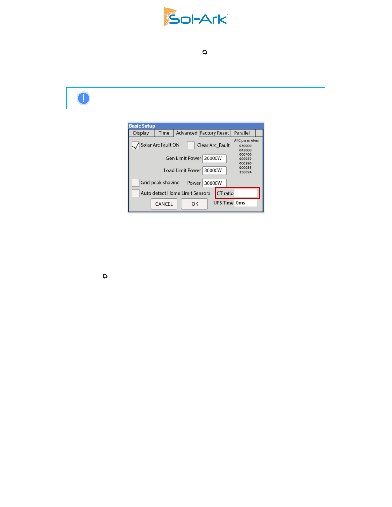
Programming CT Ratios
To program the inverter with the correct CT ratio, begin by going to the → Basic Setup → Advanced screen of the inverter, as shown in
Fig. 14. The correct CT ratio can be calculated by dividing the primary side current by the secondary side output current, the resulting
number should be multiplied by 100 before entering it into the CT Ratio setting on the inverter.
Example: 800A primary with a 5A secondary output, 800A / 5A = 160 or 16,000 ratio on the inverter.
NOTE: The maximum value that can be programmed on the inverter is 40,000
Figure 17: Settings Screen of the inverter for modifying CT Ratio
5. Automatic CT Limit Sensors Configuration
This function REQUIRES batteries to auto detect and auto correct CT orientation. AC coupled inverters need to be OFF during the
detection test. If this test is done with connected AC-coupled systems, a factory reset of the Sol-Ark must be performed. Install the CT
sensor as described previously. A battery connection and grid power are required before starting the automatic configuration.
→ Basic Setup → Advanced → 🗹 Auto detect Home Limit Sensors
Wait at least 10 to 15 seconds while the inverter performs the test. The inverter will alternate the current distribution in all lines,
determining the correct orientation of the sensor.
Operational Notes
• On “Limited power to Home” mode (no Grid Sell), HM values will read close to zero (0). Keep in mind that many sensors
can have a 1-3% error.
• To avoid selling power to the utility use “Zero Export Power” equal to or greater than 20W.
• Buying power from the grid will display positive (+) HM values, while selling to the grid displays negative (-) HM values
24 Copyright © 2025 Sol-Ark LLC
2.10 PV Rapid Shutdown
Rapid shutdown is a critical safety feature required by the National Electrical Code (NEC) for solar photovoltaic systems located on
buildings. It allows first responders to quickly de-energize the DC and AC conductors of a solar system in an emergency.
The 60K-3P-480V inverter implements rapid shutdown through the use of the emergency stop pins located in the CN2 wiring area. Pins 7/8
are a normally open (NO) contact that will trigger rapid shutdown (RSD) when closed. Closing this contact using an external e-stop button
(not included) will disable all power flows from the inverter, including the LOAD output when off-grid. When this same button is wired to
the RSD device power supply it will also trigger module level shutdown at the solar module using module level shutdown or optimizer
modules.
• Connect an emergency stop button connects to CN2, (B, B) pins 9 & 10 of the Sol-Ark.
• Rapid Shutdown Transmitters placed inside the user area of the Sol-Ark can cause interference.
• On parallel inverter installations, the emergency stop button must be wired to the designated “Master” inverter.
CAUTION: The 12Vdc power supply on Pins 7 & 8 of the 60K-3P-480V is not rated to power
Rapid Shutdown Transmitters. DO NOT CONNECT any device to these terminals
Third-party rapid shutdown transmitters should be powered by the 60K-3P-480V through an external power supply connected to the
“LOAD” output, as illustrated in Fig 15. Pressing the e-stop button will disconnect all AC outputs, cutting power to the “LOAD” connected
service panel which will initiate rapid shutdown.
Figure 18: Example Rapid Shutdown Wiring Configuration
Rapid Shutdown Product Recommendations
The following Rapid Shutdown Devices (RSDs) are compatible with the 60K-3P-480 inverter:
• Tigo TS4-A-F
• Tigo TS4-A-2F
• NEP PVG-Guard
• APsmart RSD S-PLC
• APsmart RSD-D
RSDs must be installed according to both manufacturer specifications and local electrical codes. For detailed installation procedures and
troubleshooting of Rapid Shutdown Devices, see the device manufacturer’s installation manual.
Transmitter Coil
Transmitter
Power Line
Communication
(PLC)
Emergency
Stop Button
To MPPT
Optimizers with RSD or standalone RSD
+
-
Receiver 1
Receiver n
V-
V
+
External
PSU
N
L
“LOAD”
service panel
Sol-Ark 60K Installation Guide | SK140-0019 Rev 4 25
2.11 Inverter Startup and Commissioning
NOTE: TURN ON the inverter with at least one of the following power sources:
1. Battery, 2. PV or 3. Grid/Generator
1. Verify the Battery Input
A. Voltage of the battery must be between 160V
DC
- 800V
DC
.
B. Turn ON battery modules and ensure appropriate voltage on each battery. Verify nominal voltage of battery bank according to
the battery installation manual.
C. Turn ON the external battery disconnect. Verify that the voltage at the Sol-Ark terminals is within 2% of the voltage measured at
the battery bank output.
D. DO NOT reverse polarity. DO NOT turn OFF battery disconnect if any current is flowing into or out of the battery.
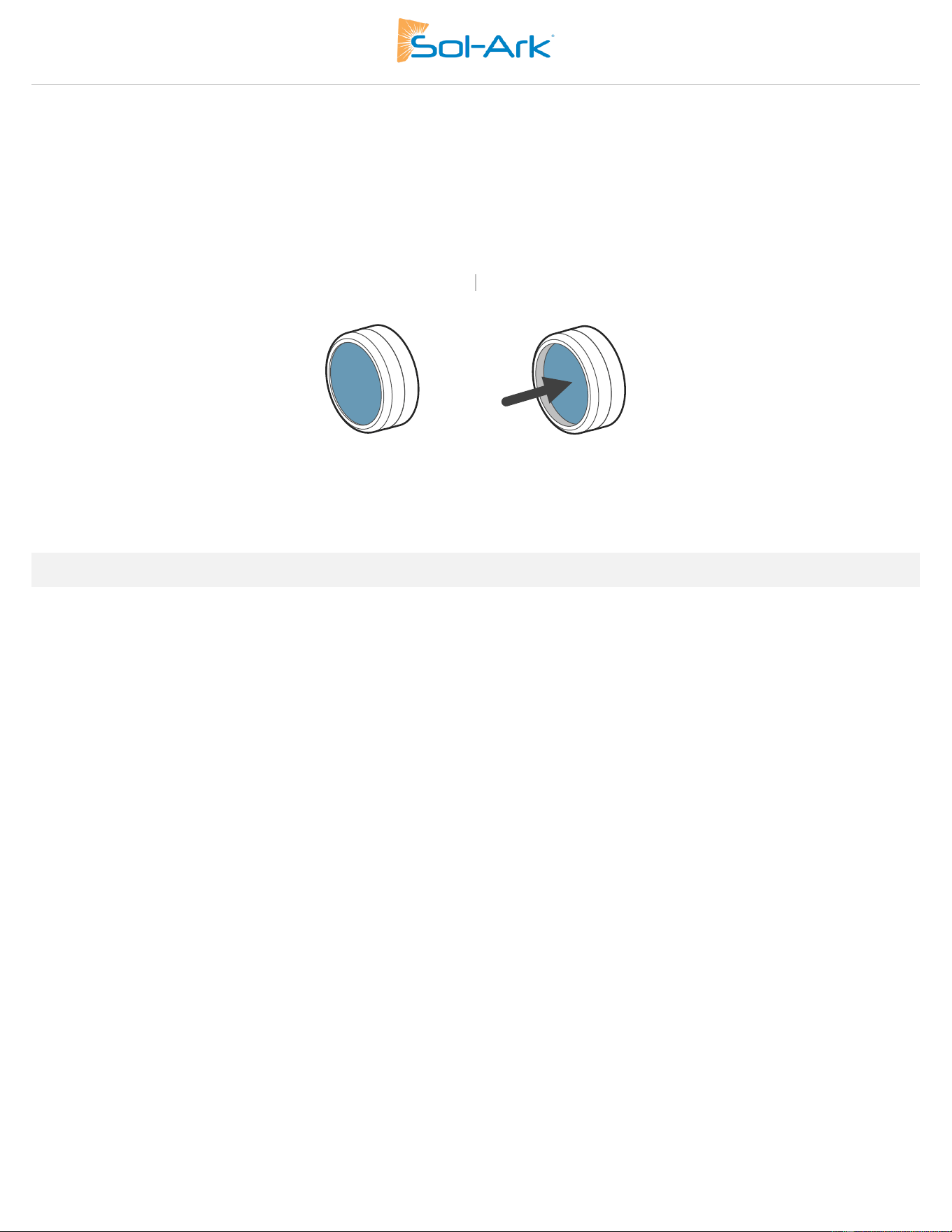
2. Verify the PV Input
A. Input voltage must not exceed 1,000V
DC
.
B. Input voltage must be above the startup voltage of 150V
DC
.
C. Do not ground PV+ or PV-.
D. Verify polarity in each PV string. Backward polarity will measure 0Vdc by the Sol-Ark and will cause long term damage.
E. PV alone turns LCD screen only. Inverter requires grid and/or batteries to operate, otherwise an “OFF” message will appear.
F. PV DC disconnect switches on the side of the inverter turn the PV ON or OFF.
Figure 19: PV Disconnect Operation
3. Verify the GRID Input
A. Verify that voltage between Neutral and Ground is 0V
AC
.
B. Verify that voltage between “GRID” L1 and “LOAD” L1 is 0V. Do the same for L2 and L3.
C. Verify the AC voltage on the “GRID” terminals using digital multimeter.
For 277/480V Wye Services
D. Measure line (L) to neutral (N) voltages on “GRID” terminals.
E. Ensure 277V
AC
on all phases to neutral or ground and 480V
AC
between all phases to each other.
For 480V Delta Services
F. Measure line (L) to line (L) voltages on “GRID” terminals. Ensure 480V
AC
between all phases to each other.
26 Copyright © 2025 Sol-Ark LLC
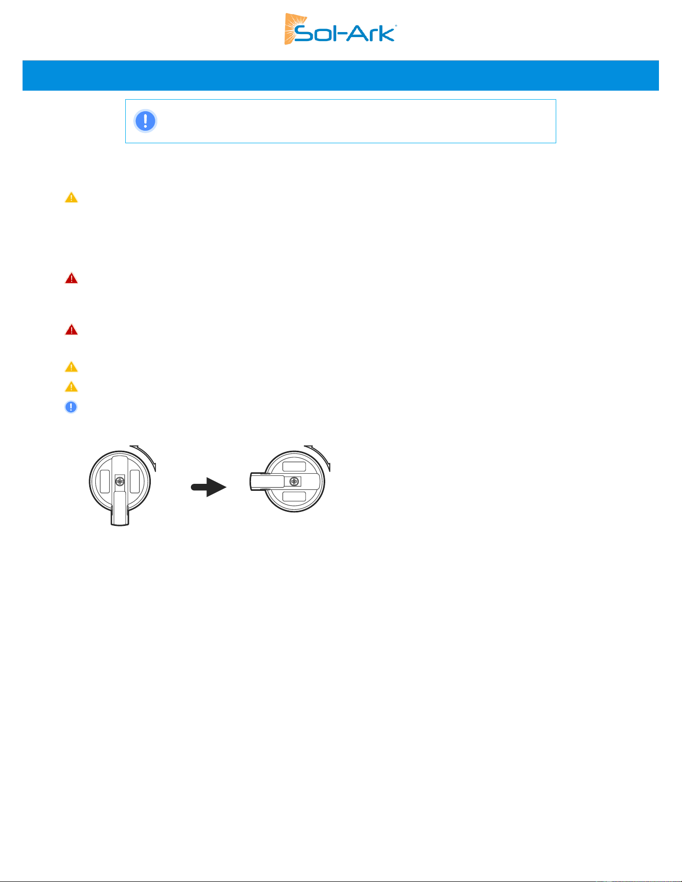
4. Power on Sol-Ark 60K-3P-480V
A. Turn ON the external “GRID” disconnect. Wait for the “AC” LED indicator to turn on.
B. Turn ON the PV DC disconnect switches. Wait for the “DC” LED indicator to turn on.
C. PRESS down the power button to the ON position. Wait for the “Normal” LED indicator to turn on. This may take a few minutes.
D. Turn ON the external battery disconnect if the system has batteries.
E. Turn ON any external “LOAD” and “GEN” breakers.
OFF
ON
Figure 20: Inverter Power Button Operation
2.12 Power Cycle Sequence
1. TURN OFF the external battery disconnect if the system has batteries.
2. PRESS the power button, making sure it is in the OFF position. An “OFF” message will appear after the “Normal” LED turns off.
3. TURN OFF the built-in PV DC disconnect switches on the side of the inverter.
4. TURN OFF all AC breakers / disconnects (“GRID”, “GEN” and “LOAD”).
5. Wait a moment (~1 min) to ensure the inverter is completely de-energized.
6. Make sure that the Sol-Ark is properly connected to the batteries, solar panels, “GRID”, “GEN”, and “LOAD”.
7. Reverse the steps to turn ON the Sol-Ark.
Sol-Ark 60K Installation Guide | SK140-0019 Rev 4 27
User Interface
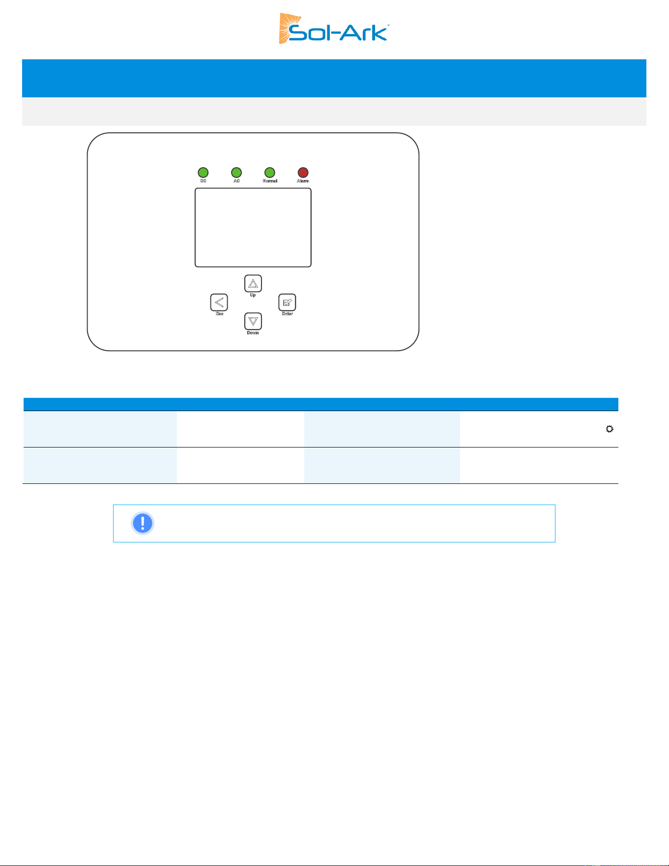
3.1 LED Indicators
Figure 21: Inverter Front Panel
DC
AC
Normal
Alarm
Green → DC PV input
connected and providing
voltage.
Green → Grid is
connected and providing
voltage.
Green → Sol-Ark is fully
energized* and operating.
Red → Alarm state. Check the
alarms menu. Home Screen→
→ “System Alarms”
OFF → Minimum MPPT voltage
not met, wrong polarity or no
PV
DC
.
OFF → Grid voltage out of
range or Off-Grid system.
OFF → Not fully energized*, in
fault state or in passthrough
mode.
OFF → No alarms / error codes /
setting change notifications
NOTE: Fully energizing the inverter requires having at least one of the following:
a) DC PV and Grid or b) Batteries
28 Copyright © 2025 Sol-Ark LLC
3.2 Main Menus
Figure 22: Main Menu Screens Overview
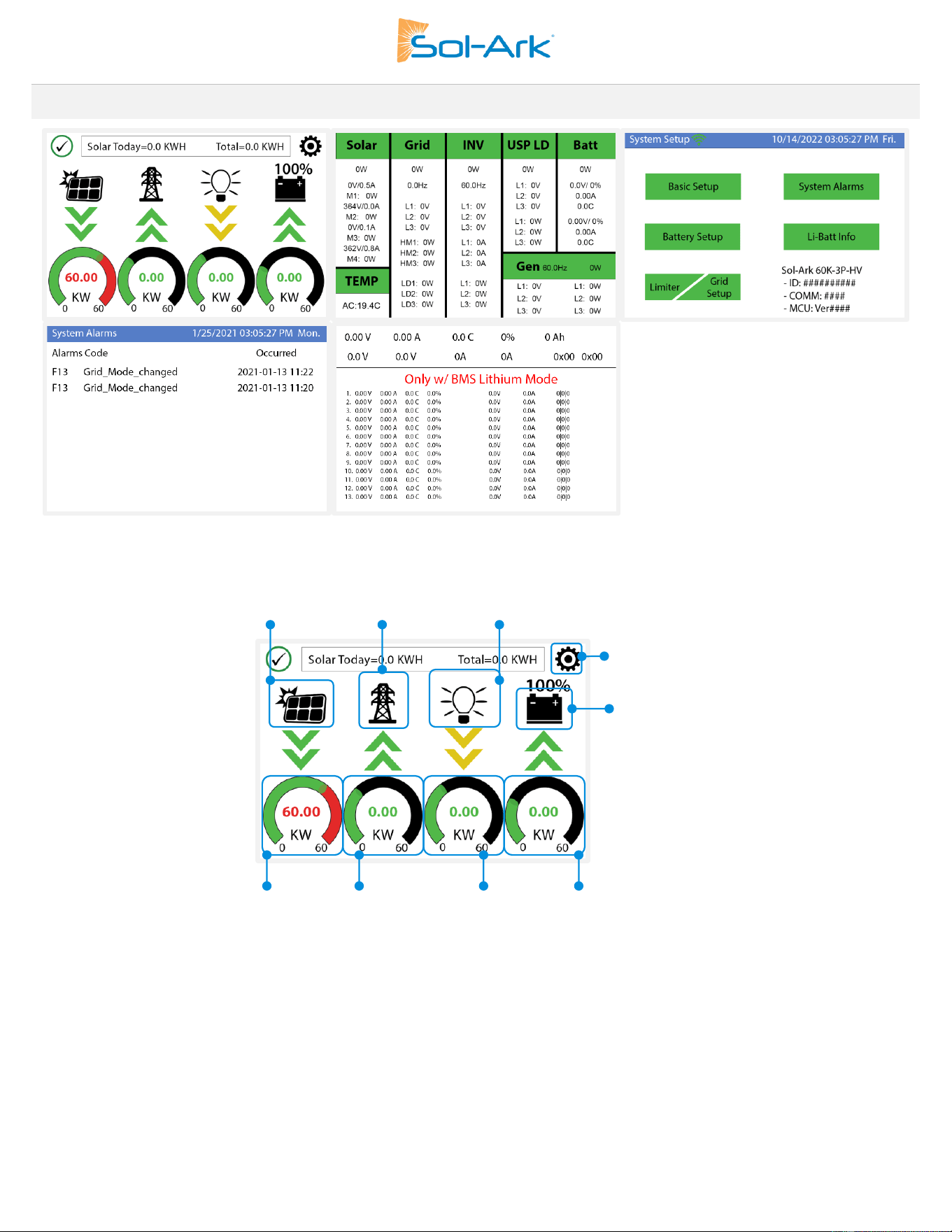
Main Screen
Figure 23: Home Screen Overview
PV power generation graph
Grid usage graph
Hold 4 s to force Smart Loads
Settings
Details Screen
Solar power production
Grid power
Sell (-) / Buy (+)
Load power
consumption
Battery power
Charge (-) / Discharge (+)
Sol-Ark 60K Installation Guide | SK140-0019 Rev 4 29
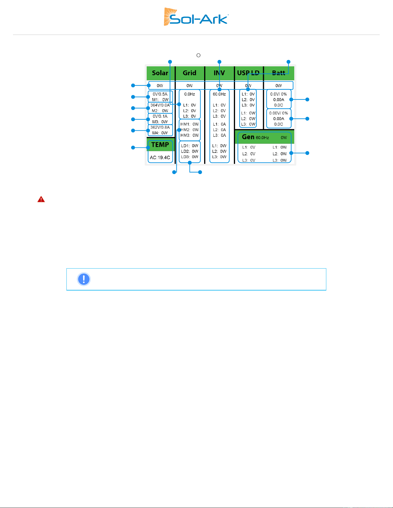
Details Screen
Figure 24: Parameters Screen Overview
• MPPT voltages MUST NOT exceed 1,000V.
• “TEMP” measures the internal temperatures of the AC conversion power electronics.
• “Grid” column measures: Voltage, Current, Power and frequency of the utility grid.
o If selling to the Grid: Watts = negative (-)
o If buying from the Grid: Watts = positive (+)
o HM: power measured by the external CT sensors. (L1, L2 & L3).
o LD: power measured by the internal sensor on “GRID” terminal. (L1, L2 & L3).
NOTE: Opposing “Grid” or “HM” values indicate an incorrect installation of CT.
See section 2.9, “Limit Sensor” for more information.
PV Power Generation Graph
A. Tap the solar panel icon to display the PV power generation graph.
B. Displays power production over time for the PV array.
C. Use up/down arrows (↑, ↓) to navigate between days.
D. Month view/year view/total production.
Grid Usage Graph
A. Tap the grid icon to display the grid usage graph.
B. Displays power drawn from grid (+) / sold to the grid (-).
C. Values above the line indicate “power bought” from the grid.
D. Values bellow the line indicate “power sold back” to the grid.
E. This view can help to determine when the peak power is used from the grid.
Total P & P
3
Φ
V, I & P of MPPT1
Internal AC temperatures
Battery 2:
V / %, I and T
GEN source V Φ, P Φ & f
Output VΦ, IΦ, PΦ & f
V, I & P of MPPT2
V, I & P of MPPT3
V, I & P of MPPT4
GRID VΦ & f
PΦ measured by external sensors
PΦ measured by internal sensors
Battery 1:
V / %, I and T
LOAD VΦ, & PΦ
30 Copyright © 2025 Sol-Ark LLC
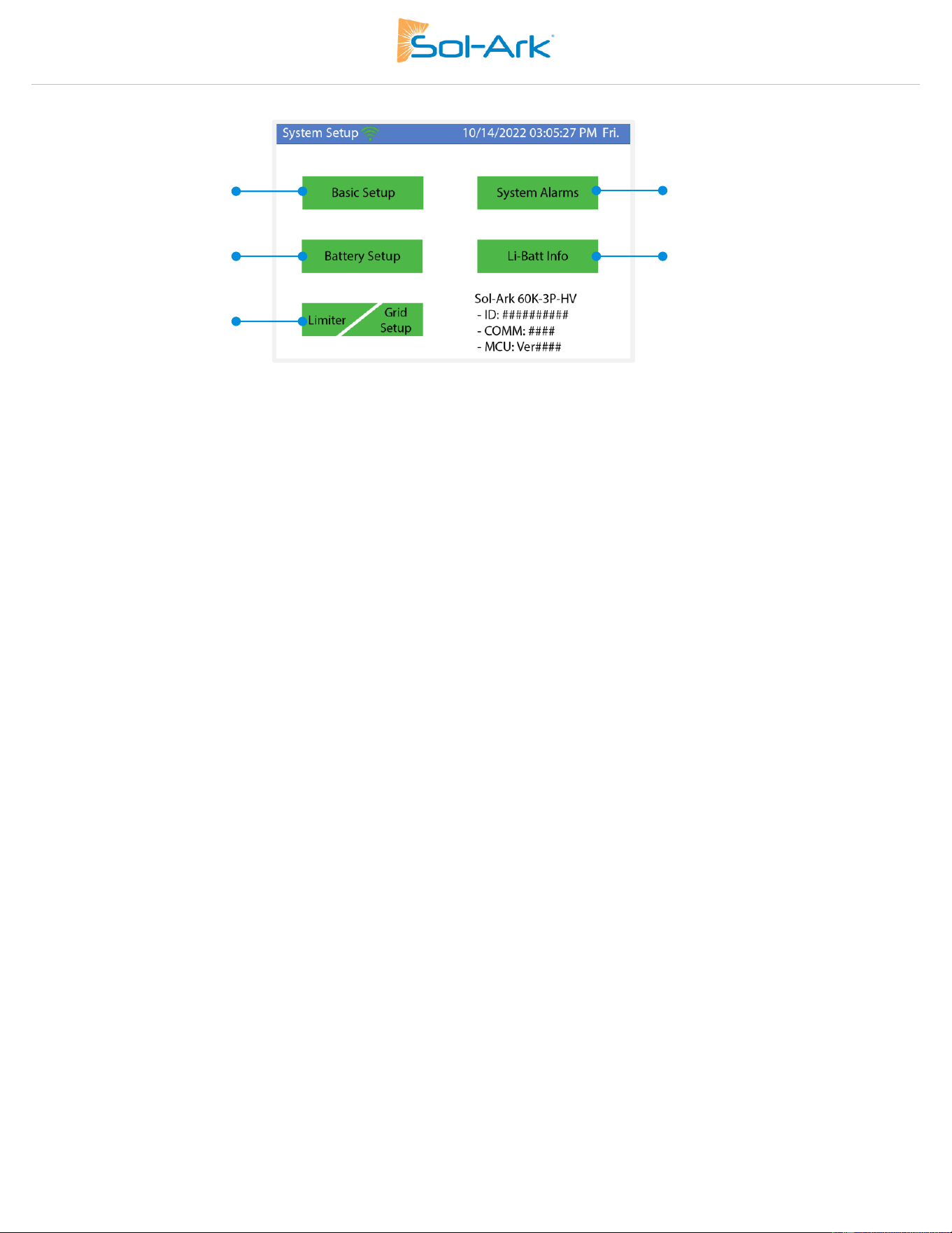
System Setup Menu
Figure 25: System Setup Screen Overview
(1)
(2)
(3,4)
(5)
Information
provided by the
BMS
Sol-Ark 60K Installation Guide | SK140-0019 Rev 4 31
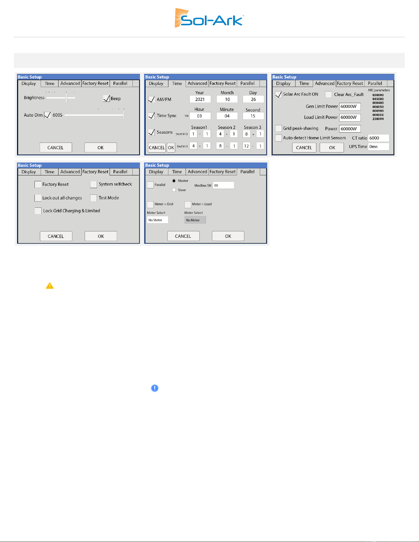
3.3 Basic Setup
Display
Brightness: Brightness adjustment (+, -).
Auto Dim: Must be always enabled to maintain the warranty of the LCD screen.
Beep: Enable / disable the alarm beep.
Time
Time Sync: Automatically syncs with the internet for daylight saving time changes (Enabling “Time sync” is recommended).
Seasons: Set up and customize the seasons for TOU. NOTE: This must be programmed using the touch screen; it’s currently not supported
on MySolArk.
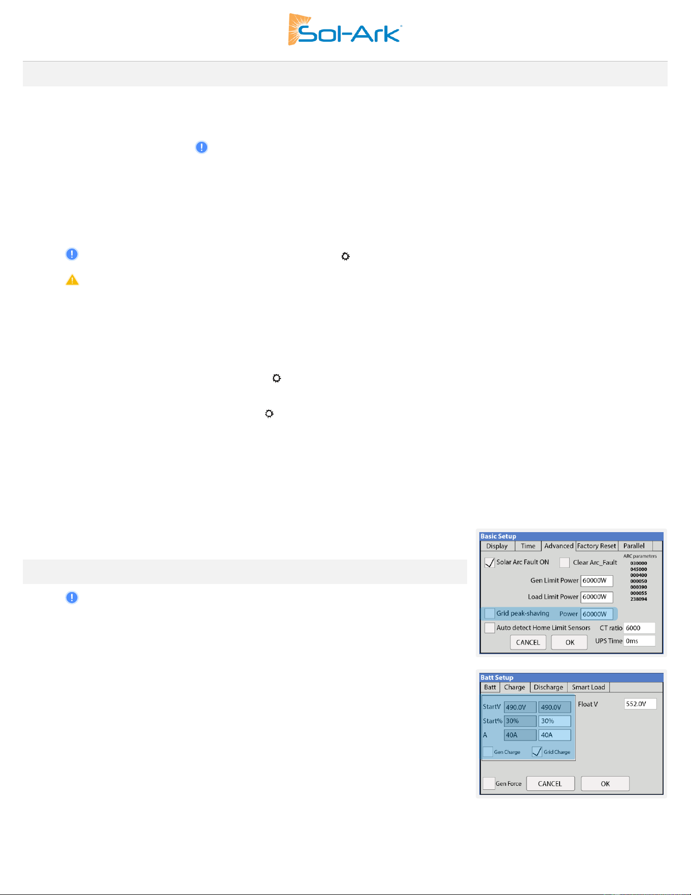
Advanced
Solar Arc Fault ON: Enables Arc fault detection algorithm on the MPPTs.
Clear Arc Fault: Command to clear an Arc Fault. It must be executed manually after the system detects an F63 Arc Fault alarm. See
section 8.1 "Sol-Ark Warnings and Fault Codes" for more detail.
Gen Limit Power: Limits the power drawn from the “GEN” AC source. The inverter will reduce battery charge when value is reached.
Load Limit Power: Sets a limit to the total “LOAD” output power. The max output power of the inverter is programmed by default.
Grid-Peak Shaving: Sets a “GRID” consumption threshold that allows use of battery backup power during peak demand. External CT
sensors are required. Peak shaving can be used on a generator provided it is wired to the “GRID” terminal.
Auto detect home Limit Sensor: Detects and auto-corrects the polarity of the CTs. See section 2.9 for details.
CT Ratio: Specifies the transformation ratio of the CT. Default value of 6000:1 for the 300A/5A sensors included with the inverter
UPS Time: Backup transfer time to essential loads upon grid disconnection. Default value of 5ms.
Factory Reset
Restrictions: Changes to these settings must be previously authorized by Sol-Ark technical support agents.
32 Copyright © 2025 Sol-Ark LLC
Parallel
Parallel: Enables communications between parallel inverters. “Master” and “Slave” inverters must be programmed.
MODBUS SN: Identification number for each system configured in parallel (1,2,3,4, n).
NOTE: See section 5, “Parallel Systems” for more information.
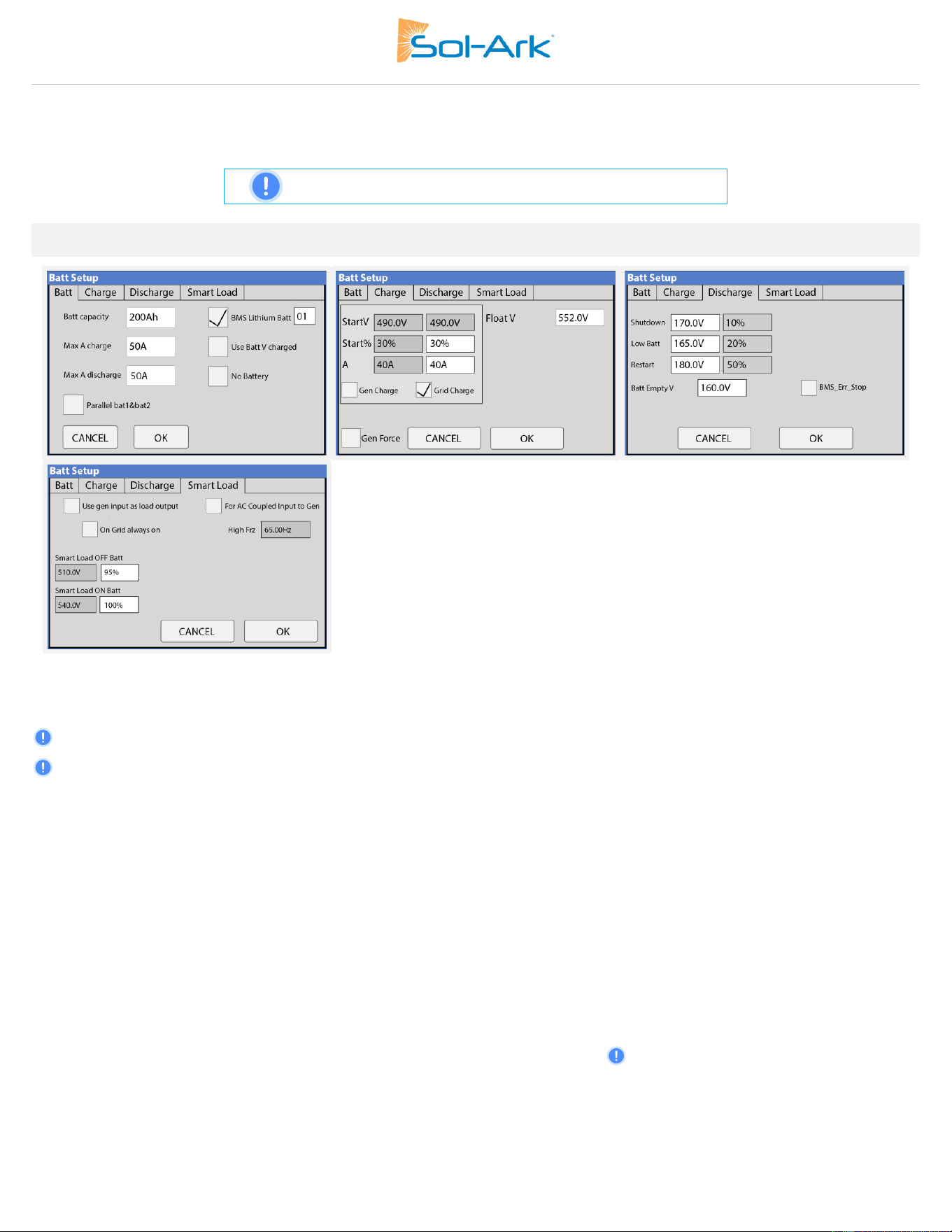
3.4 Battery Setup
Batt
Batt Capacity: Specifies the capacity of the battery bank. Value expressed in Amp Hour (Ah).
Batteries in series → Voltage adds up (V).
Batteries in parallel → Capacity adds up (Ah).
Max A Charge: Sets the maximum charge current (A) rate to the batteries when charged from solar power → 50 max allowed. 100A max
total if using both battery terminals.
Max A Discharge: Sets the maximum discharge current (A) rate from the batteries → 50A max per port. 100A total if using both battery
terminals. For off-grid systems, the battery bank will discharge 120% of this value for a 10 second surge before the inverter faults to
prevent battery damage.
BMS Lithium Batt (required): Enables closed communications with lithium batteries. Serial Number (01,02, ...) must be specified according
to communication protocol.
Use Batt V Charged: Displays battery charge in terms of voltage.
Parallel bat1&bat2: Must be checked when using both battery inputs for the same battery bank. When enabled, the inverter will expect a
single battery communication source. Follow Battery Communication instructions from section 2.3.
Charge
Float V: Lower steady voltage at which the battery is maintained after being fully charged. Not supported for Li-ion batteries.
Gen Charge: Uses the “GEN” AC source to charge the battery bank.
a. Start V: Voltage at which the system will auto-start and allow a generator or AC source to charge the battery.
b. Start %: SOC at which the system will auto-start and allow a generator or AC source to charge the battery.
c. A: Maximum rate of charge to the batteries (per terminal) from the generator or AC source (DC amps). Set value according to the
generator size.
Sol-Ark 60K Installation Guide | SK140-0019 Rev 4 33
Grid Charge: There are two scenarios in which this option is used:
a. Grid connected to “Grid” input: The inverter will limit the charge rate to the set value in “A” and the battery will charge to 100% SOC.
b. Generator connected to “Grid” input: It will be necessary to select “🗹 GEN connect to Grid input”. The system will use “Start V”,
“Start%” and “A” conditions to charge the battery and stop charging at 95% SOC. Adjustable upper limit if Time of Use is enabled.
Gen Force: Test function for generator auto-start. Enable and press OK to close normally open relay (CN2, pins 1,2) and force the
generator on. Disable and press OK to disengage. The generator will not provide power during this test if grid power is available.
NOTE: The genset must be in automatic mode if applicable and must have a
two-wire start (dry-contact, normally open) connected to the Sol-Ark.
Discharge
Shutdown: Battery voltage or % at which the inverter will shut down to protect the battery from an over discharge situation (battery symbol
on the home screen will turn red).
Low Batt: Low battery voltage or % (battery symbol on the home screen will turn yellow). Stopping point for TOU.
Restart: Battery voltage or % at which AC output will resume after previously reaching “shutdown”.
Batt Empty V: Sets the empty voltage and associates this voltage to 0% SOC. This value determines the lowest % SOC limit.
BMS_Err_Stop: Enables system stop when there is loss of battery communications.
CAUTION: Do not exceed GEN port input/output current limit of 180Aac continuous.
Smart Load
A. This mode uses the “GEN” input as a load output that delivers power when the battery exceeds a user programmable threshold or
when the Sol-Ark is connected to the grid.
B. When “🗹 Use gen input as load output” is enabled, the “GEN” input turns into an output to power high-power loads such as a water
heater, irrigation pump, AC unit, pool pump, or any other load.
C. When “🗹 On Grid always on” is enabled, the “GEN” terminal will always output power as long as the grid is connected, regardless of
battery charge.
Smart Load OFF Batt: Battery voltage or % at which the “GEN” terminal will stop outputting power.
Smart Load ON Batt: Battery voltage or % at which the “GEN” terminal will start outputting power.
Solar Power (W): Amount of PV production needed before “GEN” terminal starts outputting power.
AC Coupling Settings - (For AC Coupled Input)
A. Grid-tied systems with AC coupled solar arrays must have “🗹 Grid Sell” enabled. Ensure you are allowed to sell back to the grid.
B. To use the “GEN” terminal as an AC coupling input for micro inverters or string inverters, enable " 🗹 For AC Coupled Input to Gen”.
C. In off-grid systems, the Sol-Ark will use frequency shifting to control the AC coupled solution based on the battery SOC.
34 Copyright © 2025 Sol-Ark LLC
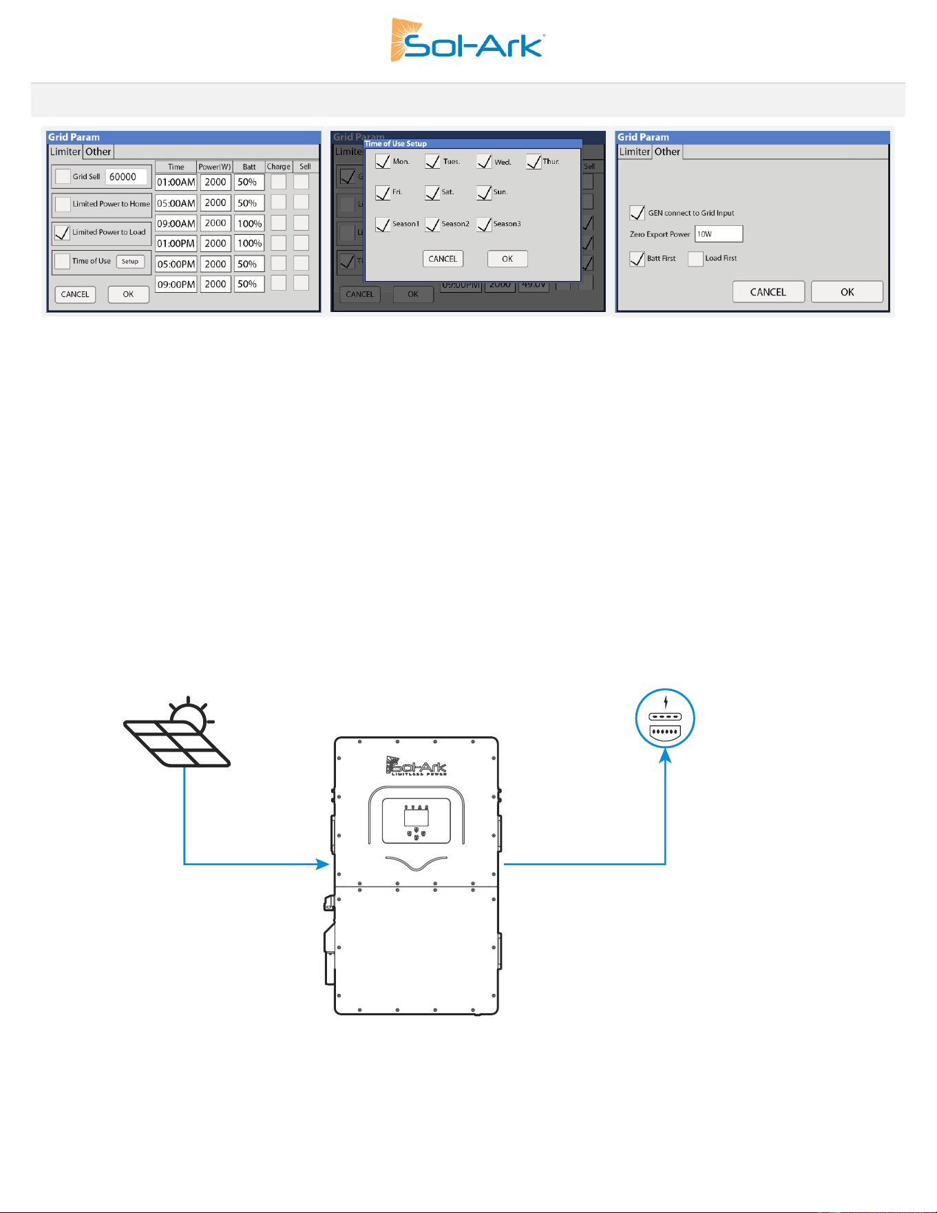
3.5 Limiter
Limiter
The Sol-Ark 60K-3P-480V inverter will simultaneously utilize different available power sources to satisfy load demand in the electrical
service panels (essential loads panel / main service panel). The following work modes allow the user to determine how power is generated
and utilized.
Grid Sell
Grid Sell: The inverter will produce as much power as it has available from PV array according to the programming. The maximum power
that can be generated from DC coupled arrays and sold to the grid is 60,000W.
Description
a. This mode allows the inverter to sell back power generated from the solar arrays up to a programmable limit.
b. The inverter will only measure loads connected to the “LOAD” terminal.
c. The inverter will measure all power in/out of the “GRID” terminal as grid either consumption (+) or grid sell back (-).
Figure 26: Operating Mode Diagram - Limited Power to Home
Sol-Ark 60K Installation Guide | SK140-0019 Rev 4 35
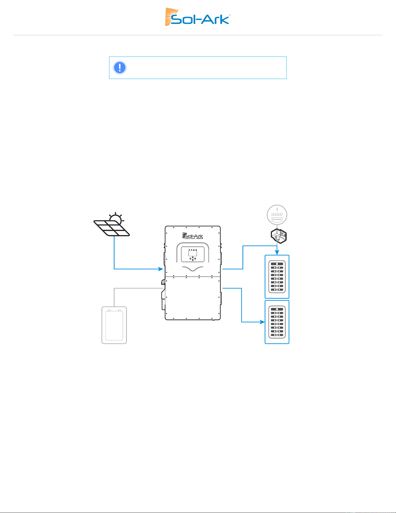
Limited Power to Home
NOTE: This operating mode REQUIRES batteries.
Limited Power to Home (Meter Zero): This mode limits the energy produced by the inverter to satisfy the total demand (essential loads
panel + main service panel). In this mode, the inverter delivers power to the “LOAD” terminal (essential loads panel) + the “GRID” terminal
(main service panel). CT sensors MUST be installed. These sensors measure load consumption in the main service panel to offset total load
demand and prevent selling to the utility. This system work mode is useful for users that don’t have a permit to sell back. See section 2.9
“Limit Sensors” for proper external CT installation.
General description
a. Power is delivered to all home loads without selling excess solar to the grid. This mode is suitable for systems where selling to the
utility grid is not allowed.
b. External CT sensors are required for proper operation.
c. Monitored loads will be the addition of the main service panel + essential loads panel.
d. Energy Priority: 1. Solar PV Power | 2. Grid Power | 3. Batteries | 4. Generator
Figure 27: Operating Mode Diagram - Limited Power to Home
Limited Power to Home + Grid Sell: This mode will NOT limit solar production to home demand. In this mode, the inverter delivers power
to the “LOAD” terminal (essential loads panel) + excess power to the “GRID” terminal (main service panel AND grid). The Sol-Ark will
monitor grid sell and load consumption simultaneously (with +/ - 3% error from CT sensors). The CT sensors MUST be installed. The
inverter will sell excess solar power up to a programmable limit. See section 2.9 “Limit Sensors” for proper external CT placement.
36 Copyright © 2025 Sol-Ark LLC
Figure 28: Operating Mode Diagram - Limited Power to Home + Grid Sell
Sol-Ark 60K Installation Guide | SK140-0019 Rev 4 37
Limited Power to Load
NOTE: This operating mode REQUIRES batteries
Limited Power to Load: This mode limits the solar production to cover “LOAD” demand (essential loads panel) exclusively. In this mode,
the system disregards loads in the main service panel and will not deliver power to the “GRID” terminal.
Description
a. Power is limited to the “LOAD” demand. It will NOT produce more power than necessary.
b. Power will NOT be delivered to the “GRID” terminal (NO grid sell).
c. Monitored loads will be exclusive to the essential loads panel.
d. This mode is recommended for off-grid applications.
e. Energy Priority: 1. Solar PV Power | 2. Grid Power | 3. Batteries | 4. Generator
Figure 29: Operating Mode Diagram - Limited Power to Load
38 Copyright © 2025 Sol-Ark LLC
Limited to Load + Grid Sell: This mode will NOT limit solar production to “LOAD” demand. The inverter delivers power to the “LOAD”
terminal (essential loads panel) + excess power to the “GRID” terminal (main service panel AND grid), however it will track ONLY “LOAD”
demand and sell excess solar up to a programmable limit. “GRID” loads cannot be measured, only the total output through the “GRID”
terminal. This mode is recommended for single inverter systems or for whole-site backup installations.
Figure 30: Operating Mode Diagram - Limited Power to Load + Grid Sell
Sol-Ark 60K Installation Guide | SK140-0019 Rev 4 39
Time of Use
Time Of Use (TOU): This mode combined with “Limited Power to Home” or “Limited Power to Load” allows the use of battery backup
power to reduce consumption from the grid during specific time intervals. Battery power will cover load demand at a programmable
power rate “Power(W)” down to a programmable “Batt (V / %SOC)”. You can configure six different time intervals over a 24-hour period
to cover a wide range of battery discharge or charge behaviors.
Description
a. Uses battery power to reduce the power consumption during user defined time intervals.
b. Power (W) dictates the rate at which the battery discharges to assist with load demand.
c. Batt (V or %) dictates the lower discharge limit or upper charge limit.
d. Energy Priority: 1. Solar PV Power | 2. Batteries (down to programmed discharge V or %) | 3. Grid Power | 4. Generator.
Figure 31: Operating Mode Diagram - Limited Power to Home + TOU
Time: Programable time intervals over a 24h period. All time slots MUST follow chronological order and must be programmed.
Power(W): Sets the maximum discharge rate of the battery during the corresponding time slot.
Batt: V or % used to specify a lower discharge limit or upper charge limit whenever “🗹 Charge” is enabled. Grid-tied systems will not
allow TOU to discharge lower than “Low Batt V/%”. Off-grid systems allow TOU discharge down to “Shutdown V/%”.
🗹 Charge: During the hours selected, it is allowed to charge batteries from an external AC source up to a programmed voltage or %. If the
external AC power source is a generator, the “Start V” or “Start %” condition must be fulfilled first. If available, the solar array will always
charge the batteries at 100% regardless of “🗹 Charge” in TOU.
🗹 Sell: Allows batteries to discharge and sell power to the grid at the programable “Power(W)” rate. “🗹 Grid Sell” MUST be enabled.
NOTE: Do not enable “Charge” and “Sell” at the same time
Other
GEN Connect to Grid Input: Specifies when a generator is connected to the “GRID” terminal.
Zero Export Power: Minimum power imported from the grid. Helps avoid selling back by ensuring constant grid consumption. The value
can be set between 1 – 100W (recommended 20W).
Batt First: Default and recommended option. Sets the solar power priority of the system to charge batteries first. Do NOT change
unless instructed by Sol-Ark technical support.
Load First: Sets the solar power priority of the system to cover loads demand first and deliver remaining power to batteries. Only
recommended for very specific situations.
40 Copyright © 2025 Sol-Ark LLC
3.6 Grid Setup
WARNING:
Consult with your utility before changing grid interconnection settings.
DANGER! SHOCK HAZARD:
Ensure inverter settings for are correctly configured for 480V Delta or 277/480V Wye Service. Failure to
configure the inverter correctly could lead to equipment failure, shock hazard, and/or serious injury.
DANGER! DO NOT USE WITH 240V DELTA HIGH LEG SERVICES:
Delta High Leg, or "Wild Leg" 3-phase systems have an unbalanced phase-to-neutral voltages that can
severely damage the 60K inverter if connected, leading to equipment failure and/or serious injury.
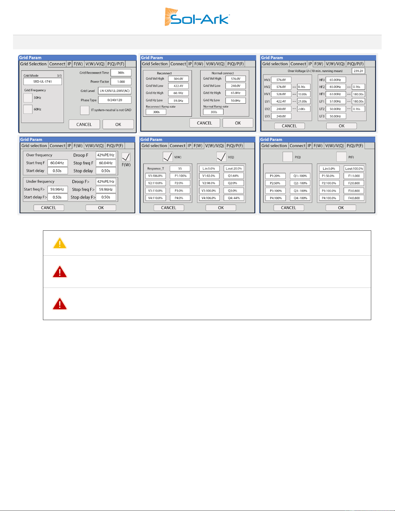
Grid Selection
Grid Mode: Tap and use navigation arrows to cycle through different grid modes:
1. General Standard: Applies general grid interconnection standards. Enables grid frequency and voltage adjustments.
This is useful for off-grid applications with backup generators.
2. UL1741 & IEEE1547: Applies UL 1741 and IEEE 1547 grid interconnection requirements and standards.
3. CPUC RULE21: Applies California’s grid interconnection requirements and standards.
4. SRD-UL-1741: Applies UL 1741SB grid interconnection requirements and standards.
Grid Frequency: Frequency of the AC sine wave.
Grid Reconnect Time: The amount of time in seconds the inverter will wait before reconnecting to the grid.
Fixed PF: Allows for power factor correction, ±0.8 to 1.0
Fixed Q: Allows for power factor correction based on desired reactive power percentage.
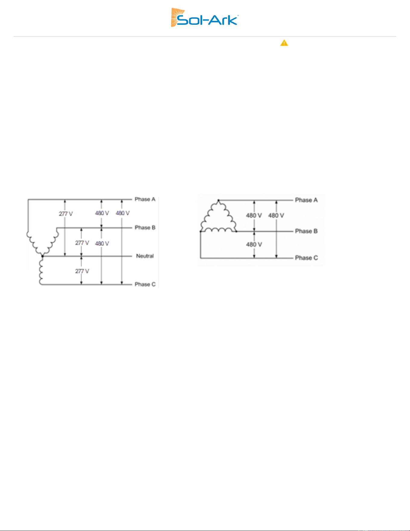
Sol-Ark 60K Installation Guide | SK140-0019 Rev 4 41
Grid Level: Tap and use navigation arrows to cycle through different nominal grid voltage levels. Grid level must be selected according
to nominal grid voltage.
1. Most Common: LN:277VAC LL:480VAC
2. LN:230VAC LL:400VAC
3. LN:220VAC LL:380VAC
Phase Type: Tap and use navigation arrows to specify phase sequence.
1. Most Common: 0/240/120: Positive sequence A-B-C
2. 0/120/240: Negative sequence A-C-B
IT system-neutral is not GND: Configures an inverter to operate in either a Wye or Delta configuration (See Fig: 29)
1. 480V Delta Configuration (3W no neutral): Checked
2. 277/480V Wye Configuration (3W with neutral): Un-Checked
Three-Phase Wye Voltage Configuration Three-Phase Delta Voltage Configuration
Figure 32 Wye versus Delta Voltage Configuration

42 Copyright © 2025 Sol-Ark LLC
Connect
Reconnect: Parameters used to determine an allowable range of frequency and voltages to dictate a reconnection to the grid after initial
grid loss. Frequency and voltages must be within these margins during Grid Reconnect Time to allow grid reconnection.
Parameters will be set automatically based on selected grid mode compliance, unless “General Standard” is selected.
Normal connect: Parameters used to determine an allowable range of frequency and voltages to retain connection to the grid following a
reconnect and normal operation.
Parameters will be set automatically based on selected grid mode compliance, unless “General Standard” is selected.
Reconnect Ramp Rate: Reconnection power ramp time in seconds.
Normal Ramp Rate: Startup power ramp time in seconds.
IP
HV1/HV2/HV3: Overvoltage protection point.
LV1/LV2/LV3: Undervoltage protection point.
HF1/HF2/HF3: Over frequency protection point.
LF1/LF2/LF3: Under frequency protection point.
F(W)
F(W): Enables the use of Frequency-Watt. The Sol-Ark regulates its power output to the grid as a function of the frequency to support grid
stabilization during over and under-frequency conditions.
Droop F: Percentage of inverter’s nominal power increase / decrease per Hert (Hz).
Start freq F: Frequency at which the inverter will start decreasing active power by the programmed Droop F percentage.
Stop freq F: Frequency at which the inverter will stop decreasing active power by the programmed Droop F percentage.
V(W) / V(Q)
V(W): Enables the use of Volt-Watt. The Sol-Ark regulates active power output to the grid as a function of voltage to support stabilization
during over and under-voltage conditions.
V(Q): Enables the use of Volt-VAr. The Sol-Ark regulates reactive power output to the grid as a function of the voltage to support
stabilization during over and under-voltage conditions.
V, P & Q: Percentage of nominal grid voltage (V) to which the Sol-Ark will reduce its active power (P) or reactive power (Q).
P(Q) / P(F)
P(Q): Enables the use of Watt-VAr to regulate reactive power output according to programable active power parameters.
P(F): Enables PF regulation according to programmable active power parameters.
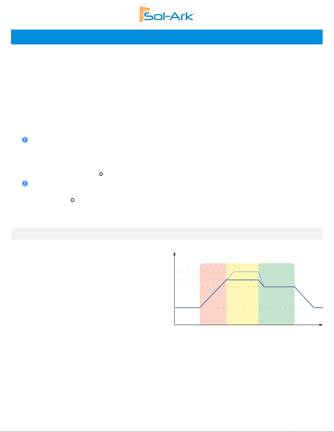
Sol-Ark 60K Installation Guide | SK140-0019 Rev 4 43
Installation Tips
Off-Grid Installation
1. Limit sensors (CTs) are not required for completely off-grid installations unless using “Grid Peak Shaving” for a generator connected
to the “GRID” terminal.
2. Connecting generators to the “GRID” terminal is recommended to facilitate the integration “GEN” connected service panel. This setup
enables the utilization of the “Smart Load” function.
3. There is no need for a transfer switch. Connect the “LOAD” output to the main panel.
4. DO NOT use “Grid Sell” mode when Off-Grid. ONLY “Limited Power to Load” (default).
5. When using a Generator in an Off-Grid situation, it is recommended to change the “Grid Mode” to “General Standard” and a “Grid
Reconnect Time” to 30 seconds. See section 2.5 “Integrating a Generator” for detailed instructions.
6. The Auto Gen-Start activates when the battery voltage (V) or percentage (%) reaches the pre-set “Start V / %” value. Subsequently, the
generator will sustain the charging process until the batteries reach approximately 95% capacity.
This is a non-modifiable upper limit unless Time of Use is enabled and programmed.
7. Remember to set the battery capacity and reasonable charge/discharge rates.
Grid-Tie PV Only, No Battery Configuration
1. Check the “🗹 No Battery” setting: → Battery Setup → Batt → No Battery . The inverter will fault momentarily.
2. A complete Power Cycle IS REQUIRED when changing the battery mode to No Battery. See section 2.12, “Power cycle Sequence”
for detailed instructions.
3. Enable “🗹 Grid Sell”: → Limiter → Grid Sell. Make sure to disable all other modes.
4. Tap the battery Icon to access the “Details Screen” and verify grid parameters and power import/export.
4.1 Battery Charge Controller
2-Stage Charging
The MPPT charge controller is 2 stage (CC/CV) type
controlled by the BMS when in closed loop mode for
optimized and safe charging. Fig 33 shows the
charging stage sequence.
Constant Current (CC) Stage
In the Constant Current stage, the battery is not at a
100% state of charge and has not yet reached the
Constant Voltage setpoint. The controller will deliver
100% of available solar power to recharge the
battery.
Constant Voltage (CV) Stage
When the battery has reached the Constant Voltage setpoint, the Sol-Ark inverter will regulate charging current to maintain the batteries
voltage at the CV setpoint, preventing overcharging. The battery is allowed to come to a full state of charge at the CV setpoint. Constant
Voltage lasts until the BMS sets the Charge Current Limit to 0A.
CC
CV
Resting
V
t
CV Setpoint
Resting V
Shutdown V
Empty V
Low Batt V
Restart V
Night
Night
Figure 33: Lead Acid Charge Controller Stages
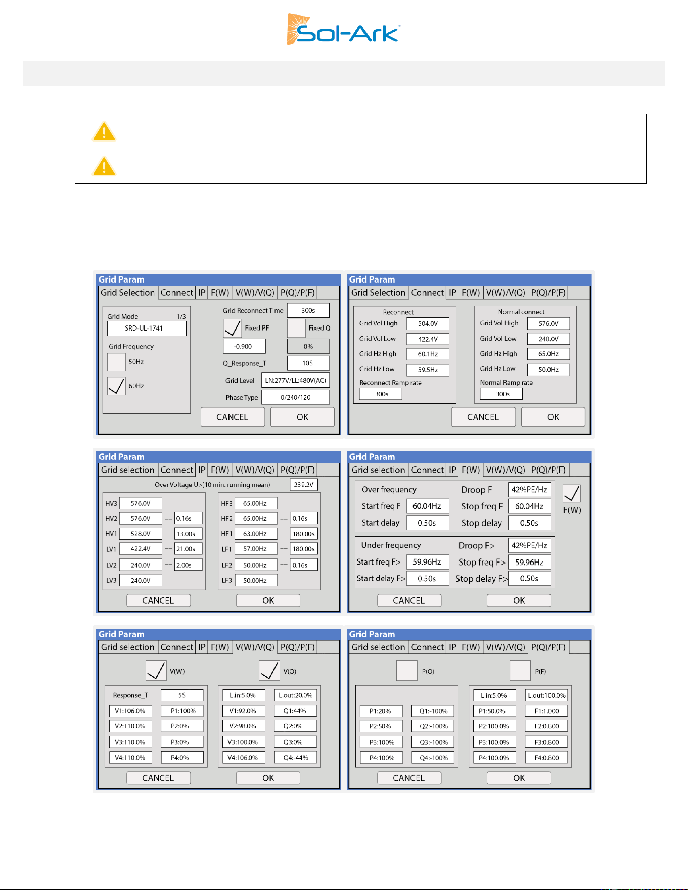
44 Copyright © 2025 Sol-Ark LLC
4.2 Grid Compliance Settings
CAUTION: Do not exceed continuous GEN port input/output of 180Aac.
CAUTION: Settings below are illustrative, exact values should be confirmed with your respective utility.
HECO Grid Compliance Verification for Sol-Ark
If HECO compliance requirements are mandated, it’s essential to program the following grid parameters according to the HECO
specifications. Follow the next GUI screens, program the settings, and verify alignment with HECO compliance.
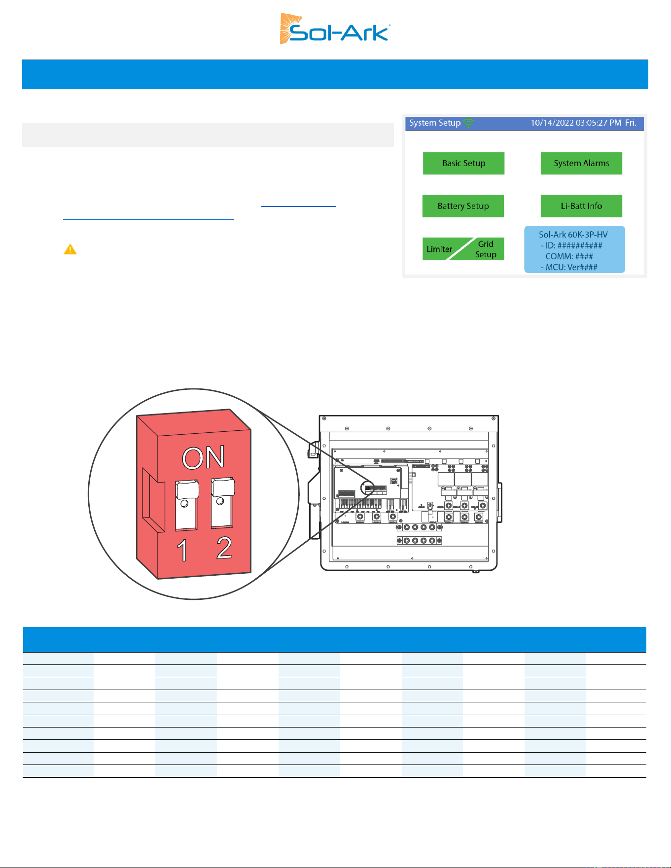
Sol-Ark 60K Installation Guide | SK140-0019 Rev 4 45
Parallel Inverters
5.1 Before Enabling Parallel Operations
A. Make sure all units in parallel have the same firmware version by verifying
the “COMM” and “MCU” numbers on Settings screen, Fig 32.
(highlighted in blue).
B. To ensure you have the latest firmware, visit https://www.Sol-
Ark.com/resources/software-updates/ to schedule an update, or contact
Sol-Ark Tech Support at [email protected]
C. Parallel systems REQUIRE that each inverter has its own HV battery /
battery bank.
D. If you do not have batteries on all inverters only parallel the units which
have a battery bank. All other units should be set to “Grid Sell” under
Settings→Limiter.
E. All GRID, GEN, and LOAD ports must be electrically parallelled with ALL parallel inverters.
DIP Switch Configuration for Parallel Systems
In parallel systems, set the DIP Switches shown in Fig 33 according to the table below.
Figure 35 Inverter Communication Settings DIP Switch
Inv 1
(Master)
Inv 2
Inv 3
Inv 4
Inv 5
Inv 6
Inv 7
Inv 8
Inv 9
Inv 10
OFF
ON
ON
ON
ON
ON
ON
ON
ON
ON
ON
ON
ON
ON
ON
ON
ON
ON
ON
ON
ON
ON
ON
ON
ON
ON
ON
ON
ON
ON
ON
ON
ON
ON
ON
ON
ON
ON
ON
ON
ON
ON
ON
ON
ON
ON
ON
ON
ON
ON
ON
ON
ON
ON
ON
Figure 34: Software Version
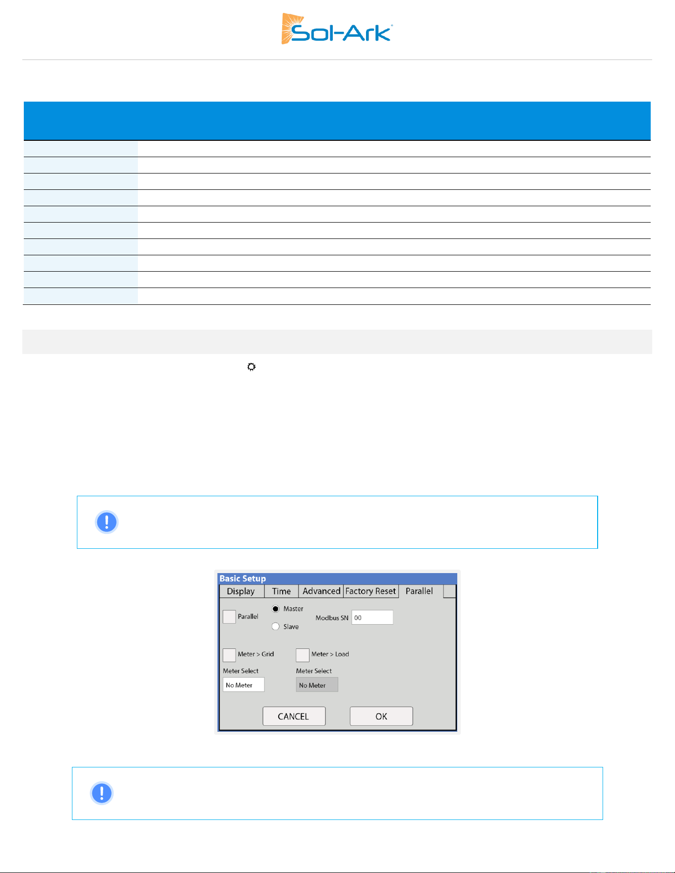
46 Copyright © 2025 Sol-Ark LLC
Parallel System Output Specifications 277/480V 3-Phase
# of inverters in
parallel
Continuous output power (kW)
Cont. Grid
Pass Through Current
(A)
Peak power 10 sec
(kVA)
1
60
180
90
2
120
360
180
3
180
540
270
4
240
720
360
5
300
900
450
6
360
1080
540
7
420
1260
630
8
480
1440
720
9
540
1620
810
10
600
1800
900
5.2 Parallel Systems Programming
1. Program each inverter for parallel operation: → Basic Setup → Parallel → “
🗹
Parallel”
2. Assign a “Master” inverter, Modbus SN: 1
3. Assign all other units as “Slave” | Modbus SN: 02, 03, 04…etc.
4. Connect communication cables between the inverters using the included RJ45 cable in daisy-chain configuration between ports:
“Parallel_1” or “Parallel_2” from Master to Slave and then from Slave to Slave thereafter.
5. Perform a power cycle (see section 2.12 “Power Cycle Sequence” for power cycle sequence instructions).
6. Once the power cycle is completed, turn on the “Slave” units FIRST. Then turn ON the “Master” LAST.
7. Inverters will likely fault momentarily with F29 and F41 codes until all inverters are ON.
NOTE: When integrating a generator, it must be connected to all the systems in parallel. The
inverter assigned as “Master” will control the two-wire start feature so the generator contacts
should be connected to this inverter only.
Figure 36 Parallel Setup Tab
NOTE: If an inverter goes into a fault state, all other units will stop and the system will automatically
try to restart. If the system faults 5 consecutive times, it will stop completely and it will require a
manual restart. See section 2.12 “Power cycle sequence” for detailed instructions.
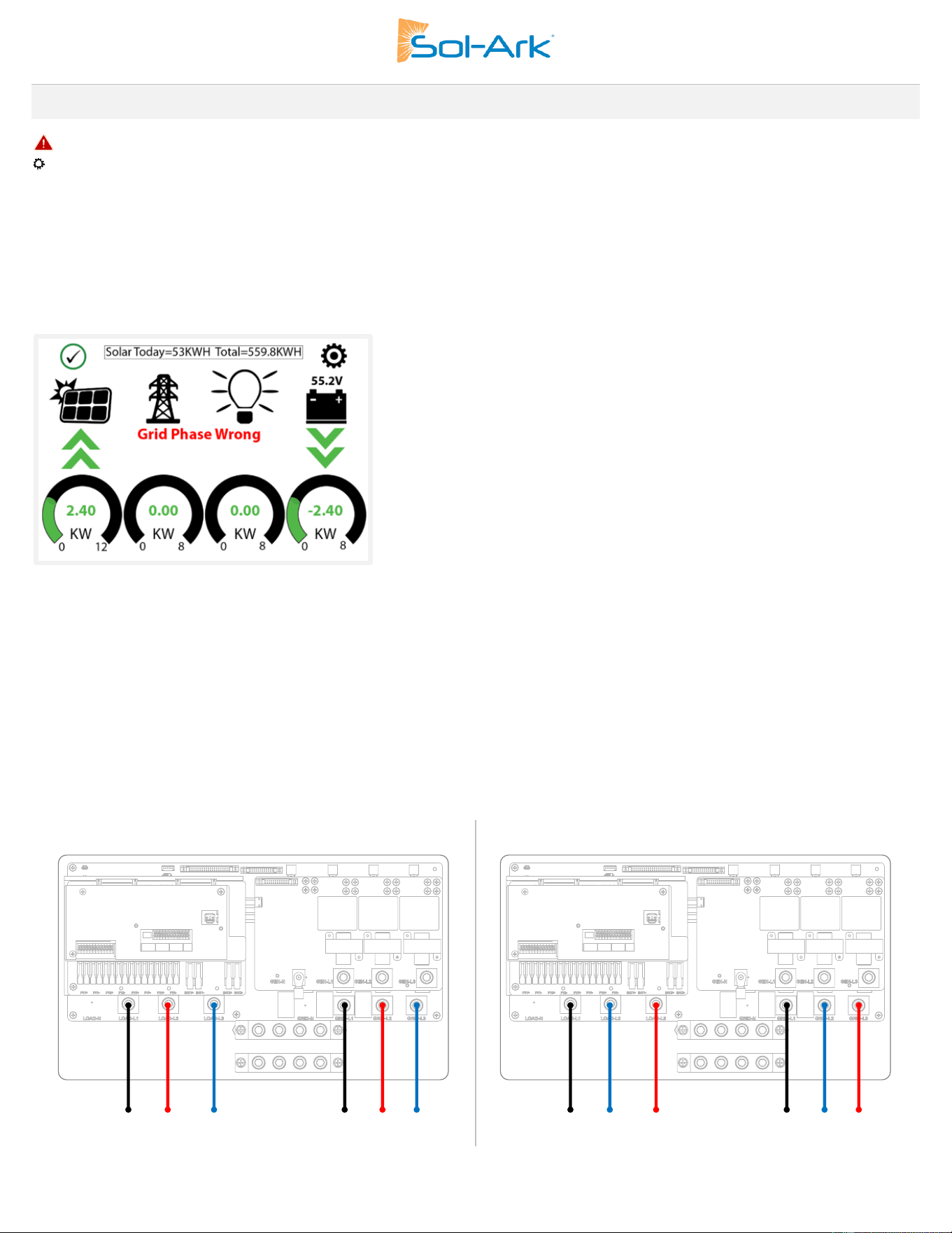
Sol-Ark 60K Installation Guide | SK140-0019 Rev 4 47
5.3 Troubleshooting Phase Sequence
If the screen of the Sol-Ark inverter shows the error in Fig 35, ensure the phase sequence follows the “Phase Type” programmed under
→ Grid Setup → Grid Selection. The message “Grid Phase Wrong” is displayed when the inverter does not detect the correct phase
sequence. This situation can cause overloads faults in the system (F18, F26, F34) even with the “LOAD” disconnected and WILL CAUSE
DAMAGE to the equipment if it is not corrected.
If the programmed phase type is “0/240/120”, ensure the wiring follows a positive sequence A-B-C. If the programmed phase type is
“0/120/240” ensure the wiring follows a negative sequence A-C-B.
Figure 37 Grid Phase Wrong Error
Troubleshooting “Grid Phase Wrong”
• Measure L-L voltages from “GRID” to “LOAD” terminals.
• Voltage between lines should be 0Vac.
• Measuring a voltage different than 0Vac means the lines are not the same phase.
Be sure to check both “GRID” and “LOAD” terminal connections; both must be correct. If the error persists you will need to check your AC
connection beyond the inverter and you will need to verify that the phases are correctly labeled from your meter.
0/240/120
0/120/240
A
B
C
A
B
C
A
C
B
A
C
B
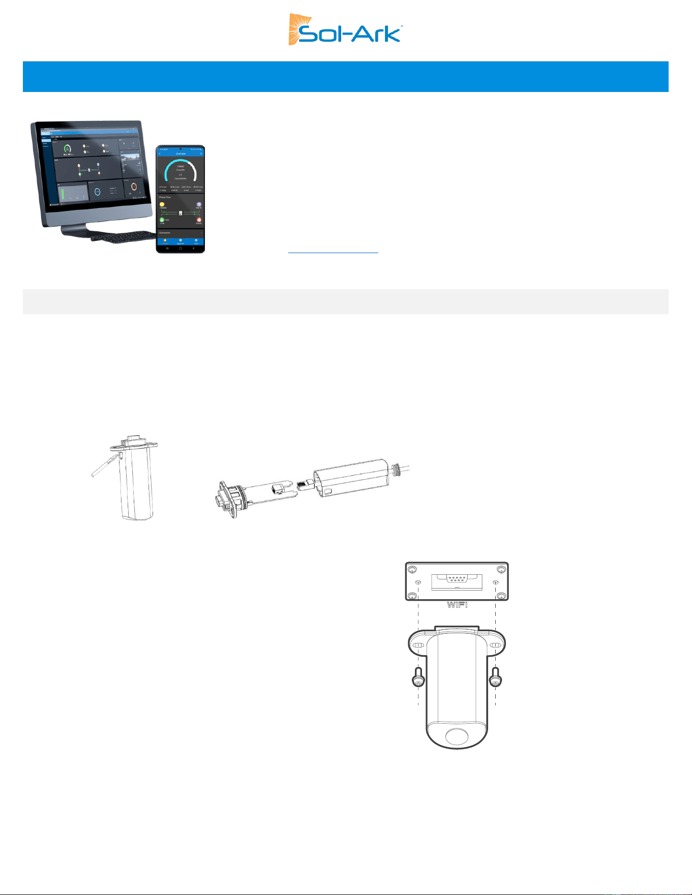
48 Copyright © 2025 Sol-Ark LLC
6. MySolArk: Remote Monitoring
"MySolArk" is a powerful and comprehensive tool designed for remote system monitoring of
Sol-Ark inverters and solar systems. This remote monitoring solution offers detailed insights into
energy generation and power consumption, allowing users to track system performance with
great precision. MySolArk displays all relevant electrical data on easy-to-understand energy
generation graphs, providing a comprehensive overview of electrical usage.
Beyond its monitoring capabilities, MySolArk offers users the flexibility to remotely adjust inverter
settings, allowing them to seamlessly configure their system from any location. This ensures that
users can fine-tune parameters to optimize performance effortlessly. With MySolArk, users can
confidently manage their solar systems and inverters to always ensure peak performance and
efficiency. Visit www.mysolark.com to access the desktop version of MySolArk.
6.1 MySolArk Setup Instructions
Connecting to MySolArk through Ethernet
A. Remove the plastic enclosure of the dongle by pressing the plastic latches with a flat screwdriver as shown in the figure below.
B. Insert the ethernet cable through the plastic enclosure and connect the cable to the RJ45 port.
C. Reassemble the dongle housing and plug the dongle into the Sol-Ark, securing it with screws. You will see solid red and green lights
after a couple of minutes.
D. Follow “STEP 1” instructions on the following page in order to create a plant on MySolArk.
Connecting to MySolArk through Wi-Fi
A. Plug the Wi-Fi dongle into the Sol-Ark DB-9 port.
B. Use two M4X10 screws to secure the dongle to the port.
C. Follow Steps 1-3 in order to:
a. Create a plant on the MySolArk monitoring platform.
b. Connect the dongle to MySolArk through a Wi-Fi network.
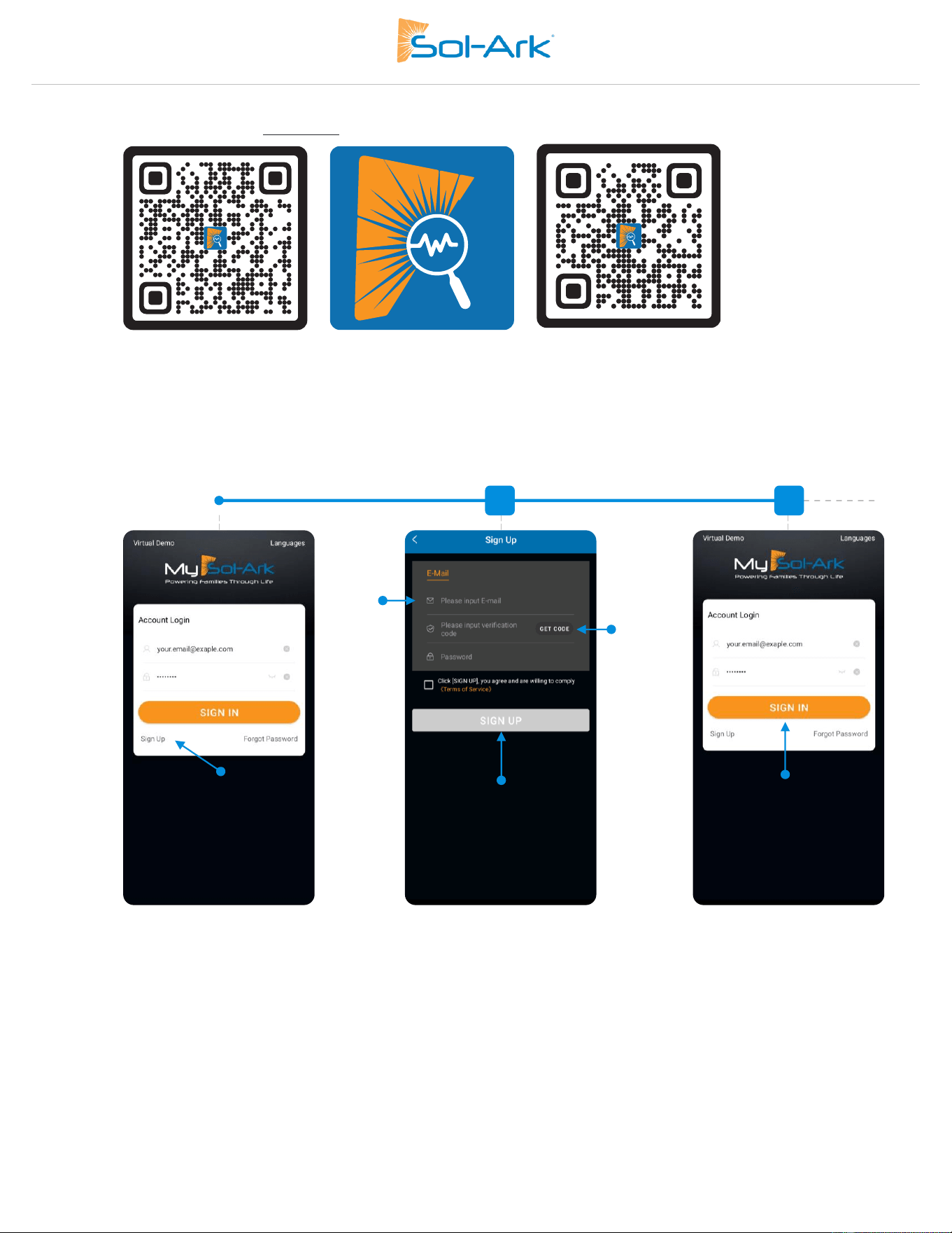
Sol-Ark 60K Installation Guide | SK140-0019 Rev 4 49
Step 1: Create a “Plant” on MySolArk
A. Download and install the “MySolArk” app for android or apple smartphones. QR codes are provided below.
Google Play
Store
MySolArk
Apple App
Store
B. Create a MySolArk account and log in.
1
2
3
4
5
Login
Signup
E-mail & verification code
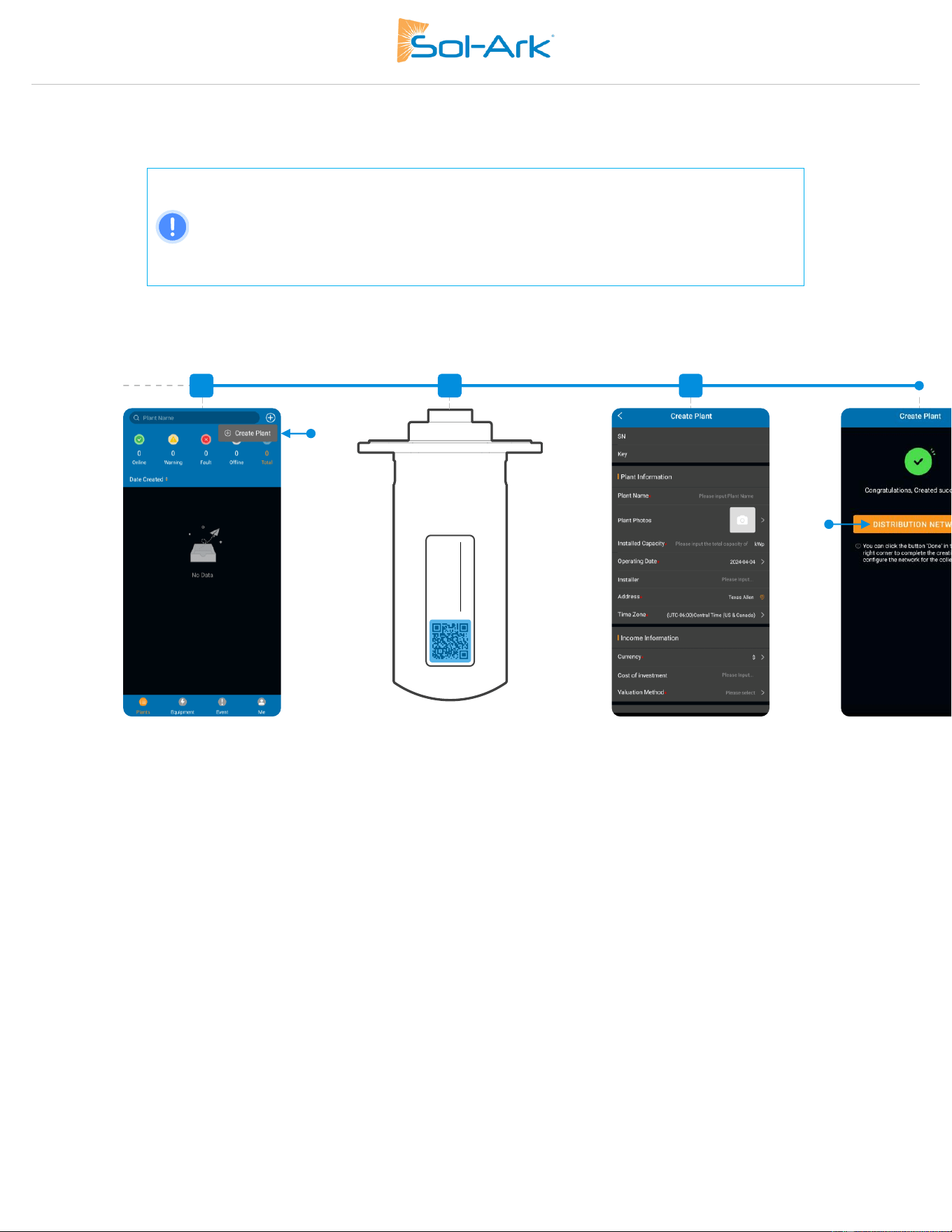
50 Copyright © 2025 Sol-Ark LLC
C. Create the Plant.
For Installers:
Create the plant and configure the system before sharing it with the owner.
After creating and configuring the plant, the installer can share and grant manager
permissions to the owner by navigating to My Plants → … → Share → Add Account.
The homeowner must create their own MySolArk account first.
6
EA##########
############
8
7
9
Create plant
Configure network
Plant information
Scan QR code or type manually
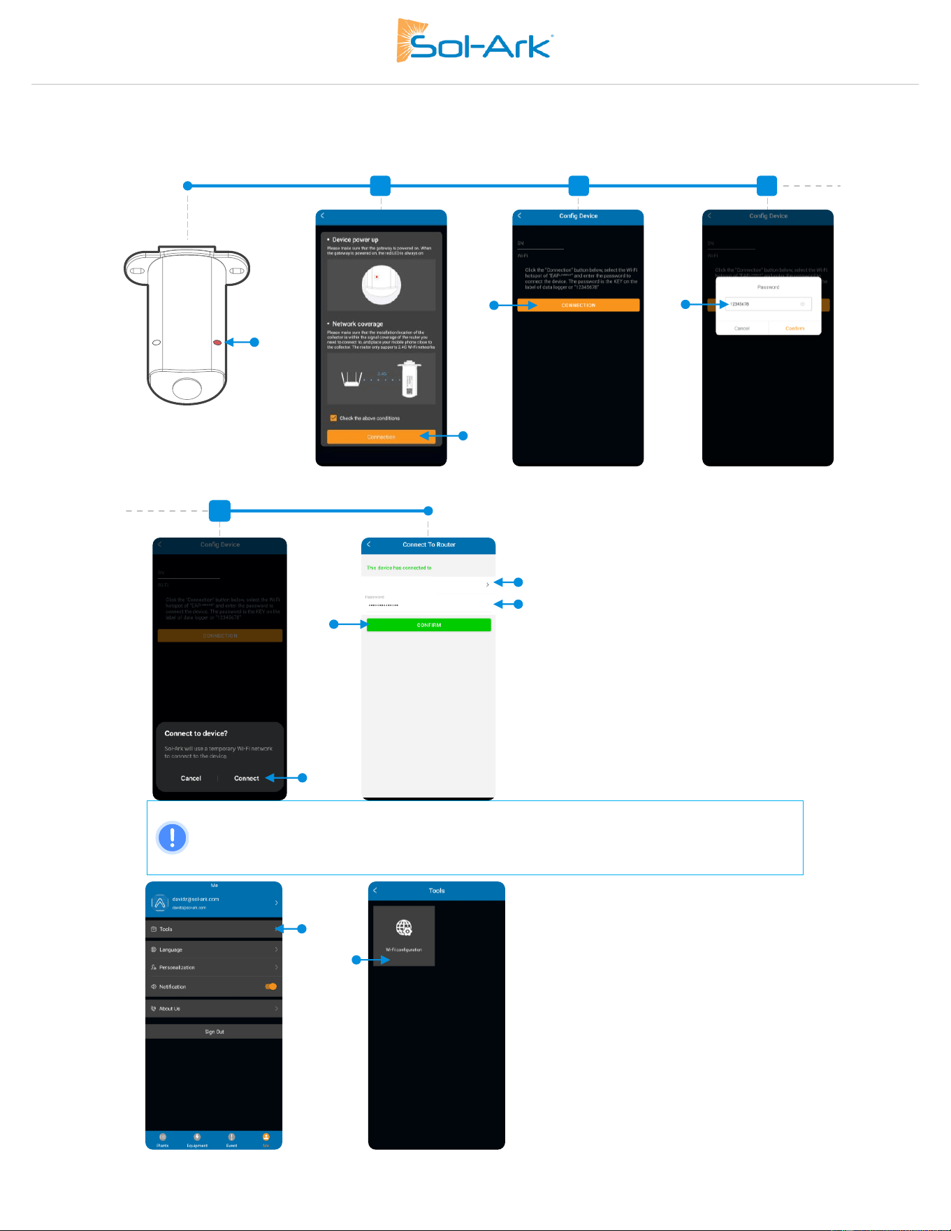
Sol-Ark 60K Installation Guide | SK140-0019 Rev 4 51
Step 2: Configure Wi-Fi network though MySolArk
D. Configure Wi-Fi network.
Note: You can access the Wi-Fi configuration tool at any other time by tapping Me at the
bottom right corner, then Tools → Wi-Fi configuration. Step 3 shows another method of
connecting the Wi-Fi dongle to a local network through an IP address.
Password
Connection
Turn inverter ON
to power dongle
Accept conditions
11
12
10
13
E4A0########
EAP-#####
E4A0########
EAP-#####
1
2
Confirm Wi-Fi network
Connect
E4A0########
EAP-#####
EAP-#####
My local network
My local Wi-Fi network
17
15
16
14
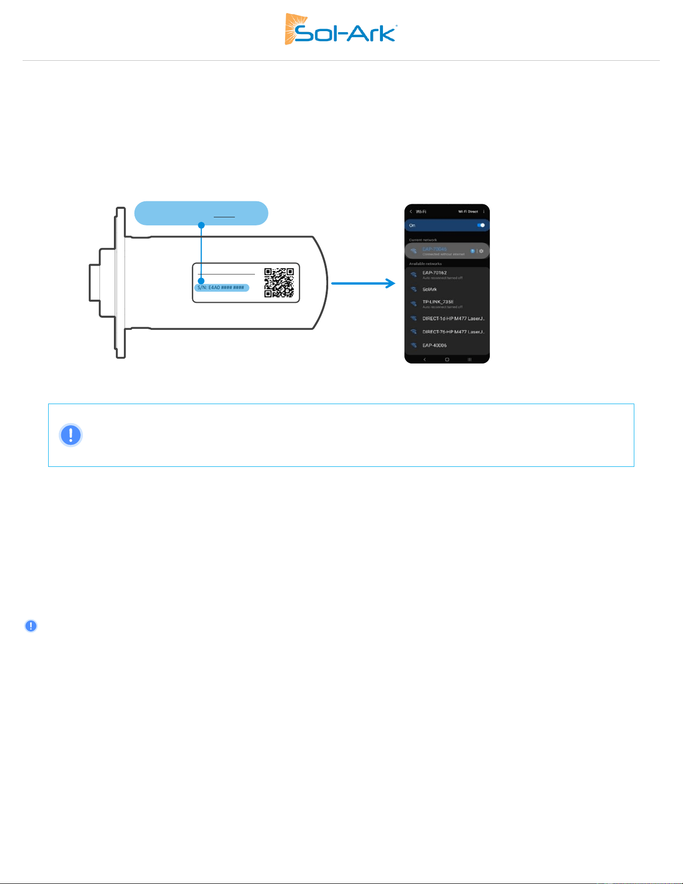
52 Copyright © 2025 Sol-Ark LLC
Step 3 (alternate method): Configure Wi-Fi Network Through an IP Address
An alternative to the “Distribution Network” configuration at the end of step C or using the “Wi-Fi configuration” tool, is by configuring a
Wi-Fi network through an IP address.
A. On a smart phone or computer, connect to the EAP-##### network. You can do this by going to: Settings → Wi-Fi → Select the
EAP-##### network → Password= 12345678. The EAP-##### network contains the last 5 digits of the Dongle Serial Number. You
can find this number on the label.
B. A message such as “Connected without internet” will appear once the device is connected to the EAP-#####.
Figure 38: Locating the Dongle Network Name
EAP-##### Network Password= 12345678
NOTE: The Wi-Fi dongle does NOT provide internet access. It needs an external internet provider to connect to.
The dongle is compatible with Wi-Fi signal broadcasted at 2.4 GHz (it is not compatible with 5 GHz networks)
C. Once connected, open an internet browser on that same device such as Safari, Chrome, Firefox, Edge, or another browser.
D. On the address bar, type the following IP address: 10.10.10.1 as shown in the figure below. If you cannot access the configuration
page, try again on a different device.
E. Scroll down to the "Wlan Connection" section and press the “Scan” button to scan for local Wi-Fi networks.
F. Nearby Wi-Fi networks will appear. Select the local network you would like to connect to, input your credentials, and tap
“Connect”.
G. Once connected, a “Connection Successful” message will appear. Press the “Save” button next to “Scan” to save settings.
H. Wait a moment (~5 minutes). The dongle will then connect to the Wi-Fi network and will now have access to MySolArk.
NOTE: DO NOT connect to the EAP-##### network as that is the Wi-Fi dongle itself. The device does not provide internet access.
E4A0 #### ####
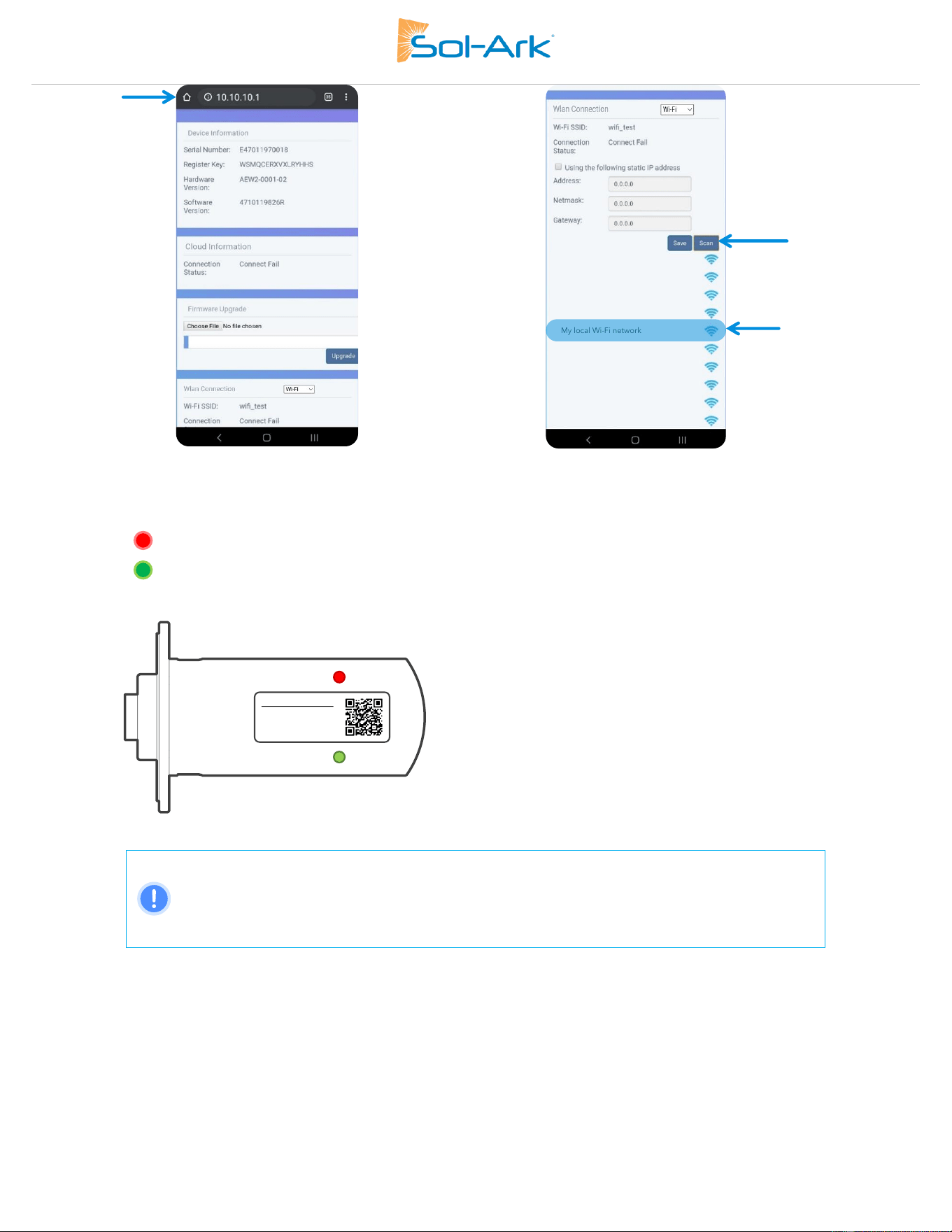
Sol-Ark 60K Installation Guide | SK140-0019 Rev 4 53
a) Internet browser IP address
b) Wi-Fi network scan
If the connection succeeds, you’ll see the following LED indicators.
o SOLID : Connected and powered by the Sol-Ark inverter.
o SOLID : Connected to the router and to MySolArk.
Figure 39: Wi-Fi dongle LED indicators
NOTE: Local Dongle Connection
Connecting through the local hotspot broadcast by the dongle is only meant to provide access to
the Wi-Fi dongle for troubleshooting or firmware updates.
Users must still create a MySolArk account and must create a Plant to access monitoring data.
Example 1
Example 2
Example 3
My local Wi-Fi network
Example 5
Example 6
Example 7
Example 8
Example 4
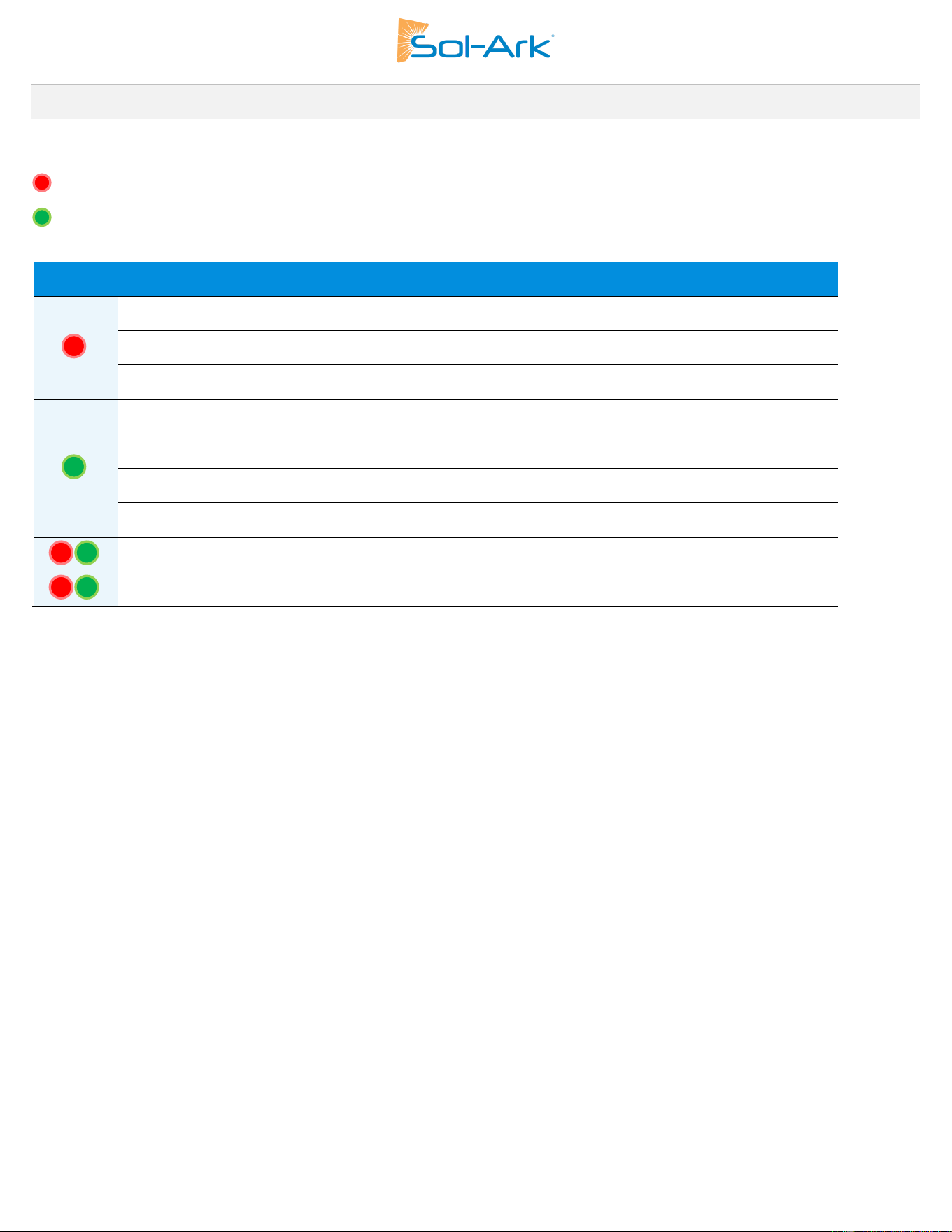
54 Copyright © 2025 Sol-Ark LLC
6.2 LED Indicator and troubleshooting
When both the red and green LEDs on the Wi-Fi dongle are consistently illuminated, it signifies normal operation, while flashing indicates
data transmission. If this isn't the case, reference the next table of LED indications for troubleshooting and corrective measures.
RED LED: Device communication indicator.
GREEN LED: MySolArk server communication indicator.
LED
State
Indication
Initial flashing, then constant illumination
Normal communication.
Initial flashing but no further illumination
Communication failure. Check proper device connection.
LED not illuminating
Power supply or device is abnormal. Contact technical
support.
5 second illumination interval
Normal communication.
1 flash every minute
Router not connected.
3 flashes every minute
Connected to router but no internet access. Usually, a VPN or
firewall issue. Ports 80 and 51100 must be enabled.
4 flashes every minute
Device communication error. Contact Sol-Ark Support.
2 synchronized flashes
Ethernet cable inserted
3 synchronized flashes
Ethernet cable disconnected

Copyright © 2025 Sol-Ark LLC | SK140-0015-004 55
7.0 Wiring Diagrams
CAUTION: These diagrams are illustrative and not exhaustive. They may not cover all variations required by local codes and
should not be solely relied upon for permitting or warranty purposes. Consult relevant authorities and ensure full compliance
before installation. Installers should exercise caution, seek professional advice when necessary, and adhere to established
electrical standards and regulations during all installations.
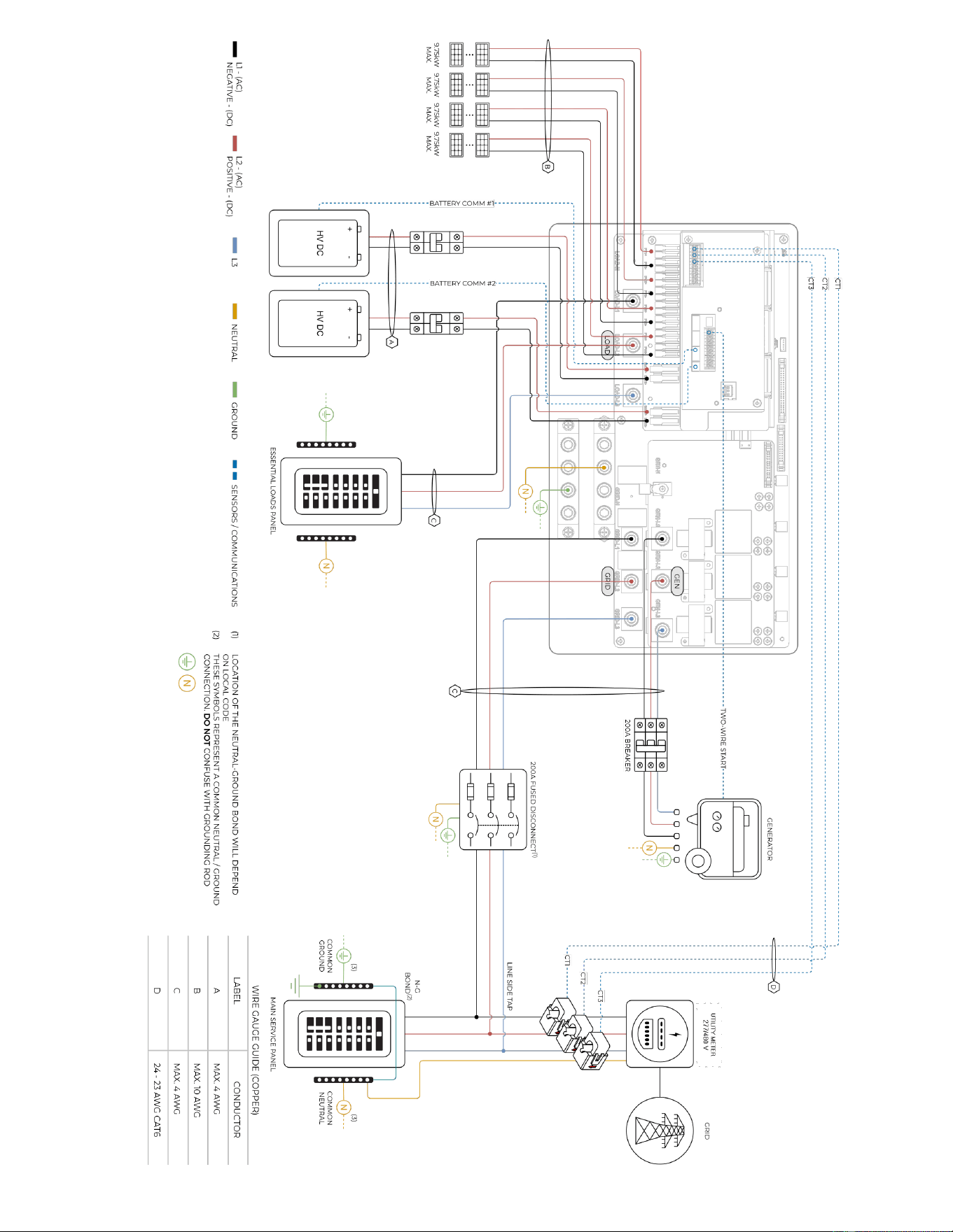
56 Copyright © 2025 Sol-Ark LLC | SK140-0015-004
Sol-Ark 60K-3P-480V
Standard Wiring Diagram
Diagram 01
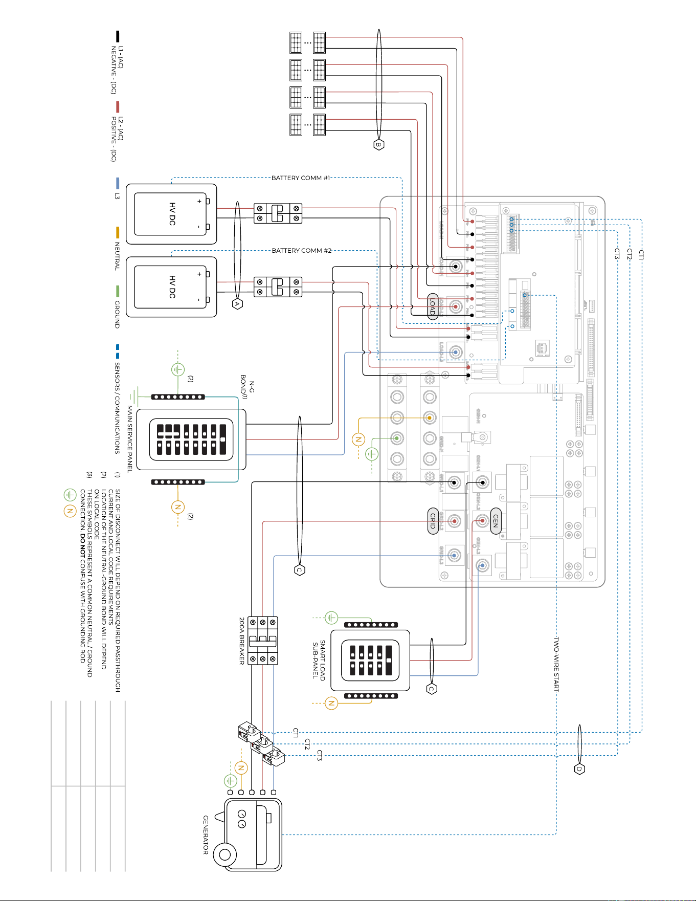
Copyright © 2025 Sol-Ark LLC | SK140-0015-004 57
Sol-Ark 60K-3P-480V
Standard Wiring Diagram
– Off Grid
Diagram 0
2
78 kW
MAX.
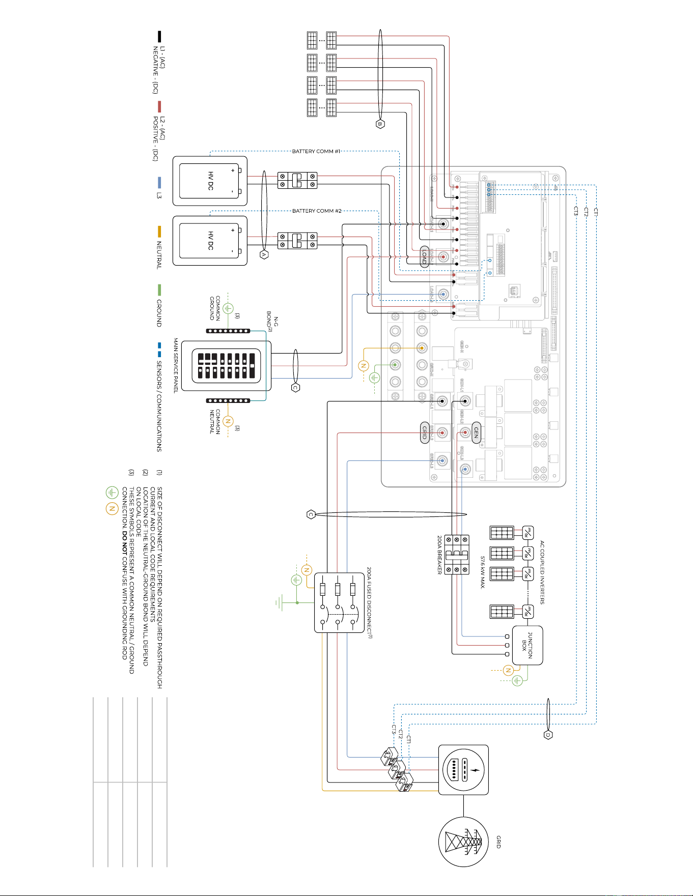
58 Copyright © 2025 Sol-Ark LLC | SK140-0015-004
Sol-Ark 60K-3P-480V
Standard Wiring Diagram
– AC Coupling
Diagram 0
3
78 kW
MAX.
UTILITY METER
277/480V
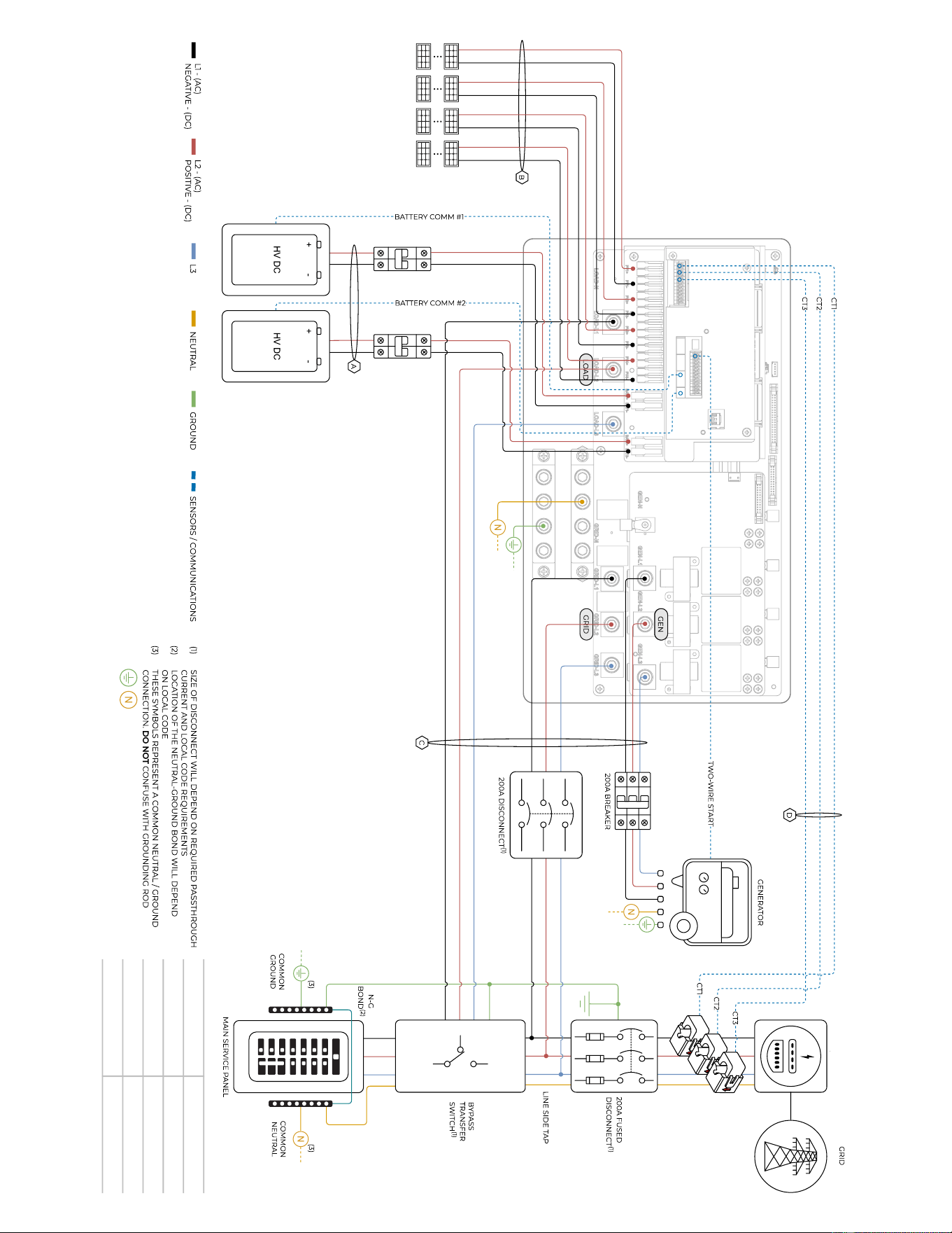
Copyright © 2025 Sol-Ark LLC | SK140-0015-004 59
Sol-Ark 60K-3P-480V
Standard Wiring Diagram
– Bypass Transfer Switch
Diagram 0
4
78 kW
MAX.
UTILITY METER
277/480V
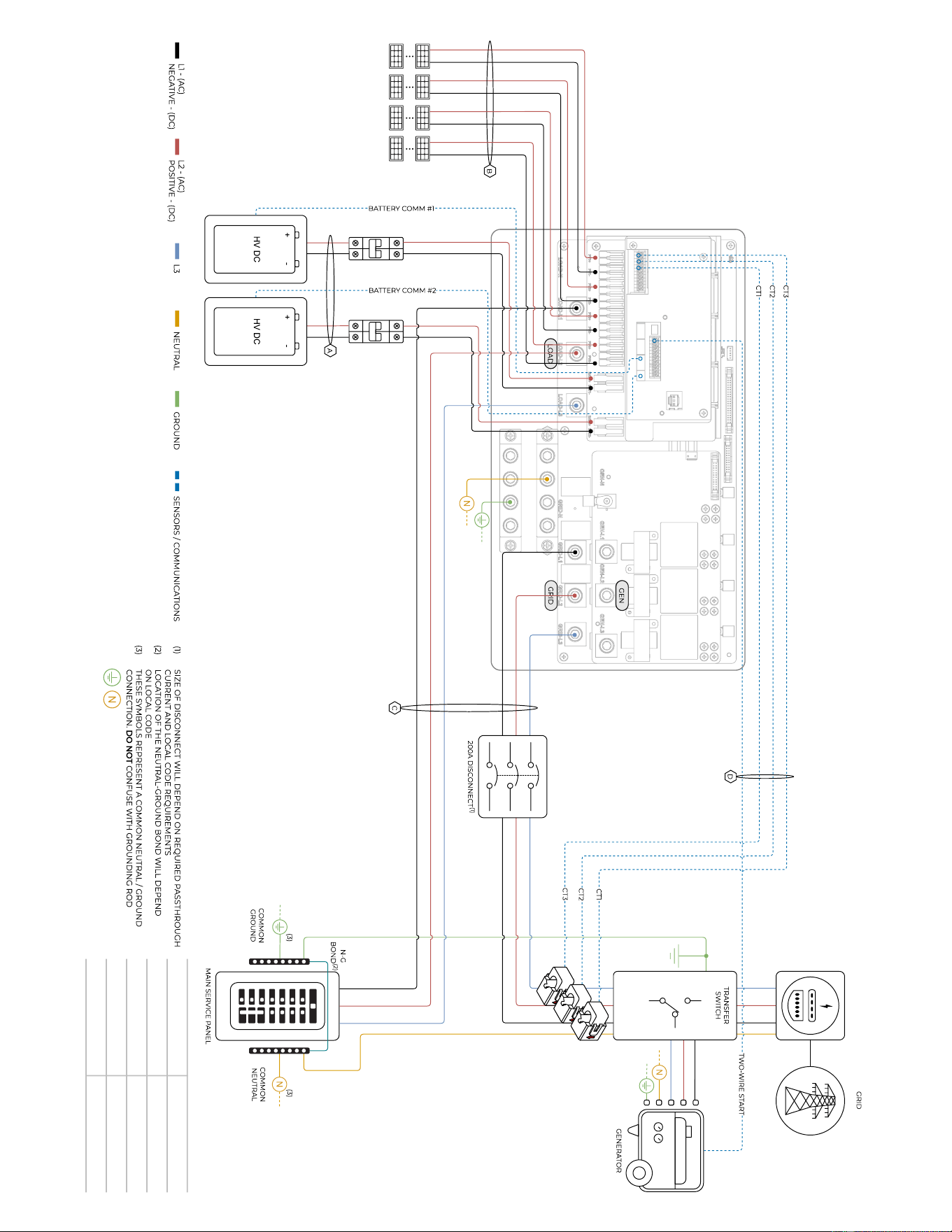
60 Copyright © 2025 Sol-Ark LLC | SK140-0015-004
Sol-Ark 60K-3P-480V
Standard Wiring Diagram
– Standby Generator
Diagram 0
5
78 kW
MAX.
UTILITY METER
277/480V
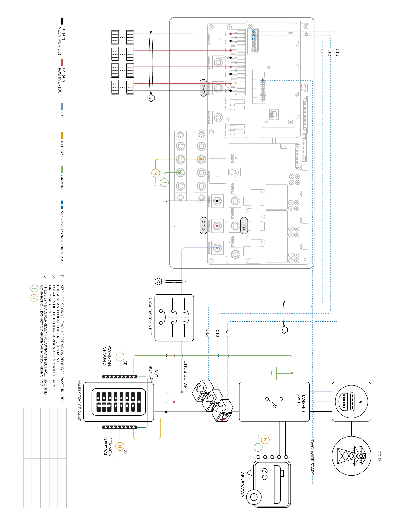
Copyright © 2025 Sol-Ark LLC | SK140-0015-004 61
Diagram 0
6
Sol-Ark 60K-3P-480V
Standard Wiring Diagram
– Grid-Tide Only with Standby Generator
78 kW
MAX.
UTILITY METER
277/480V
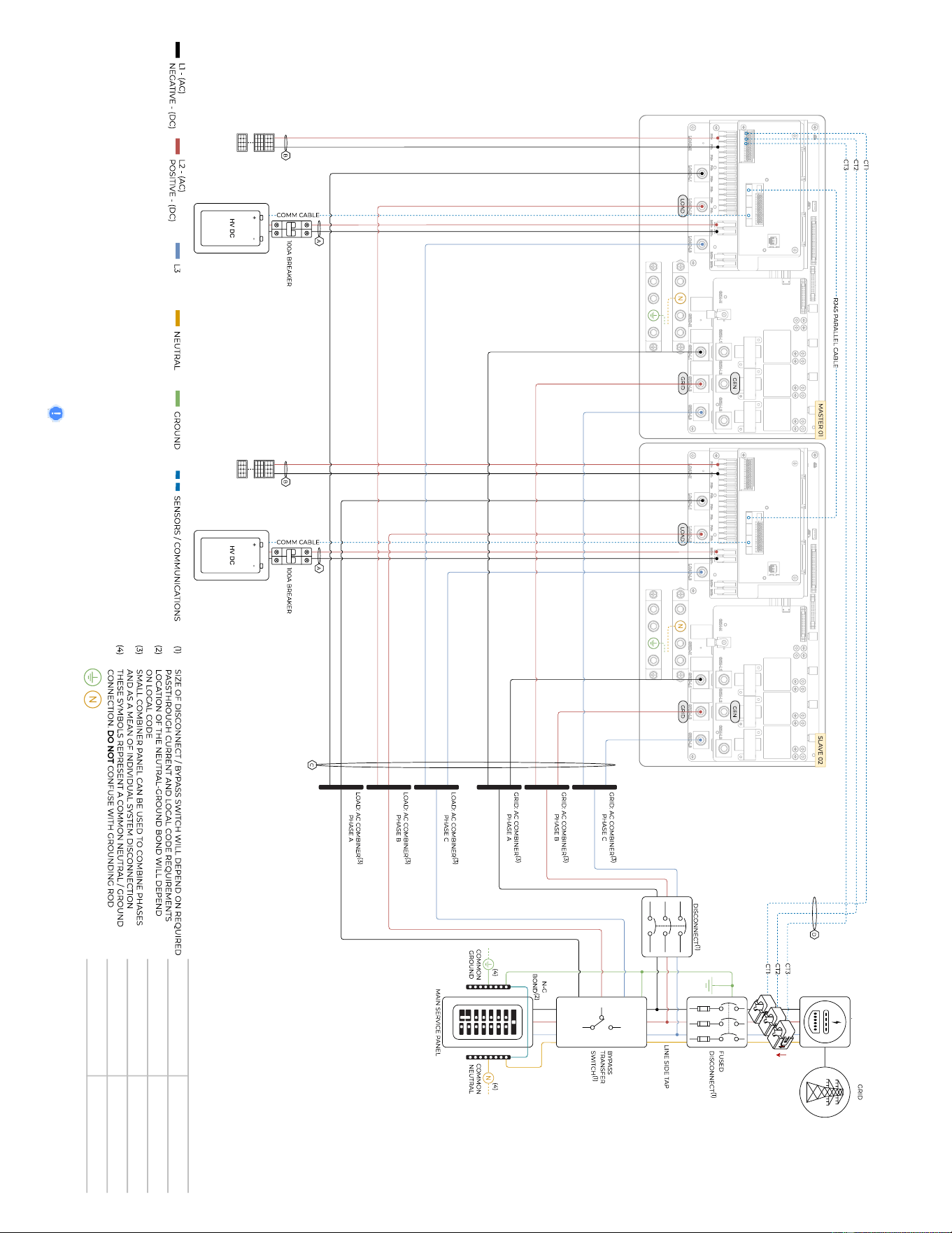
62 Copyright © 2025 Sol-Ark LLC | SK140-0015-004
Sol-Ark 60K-3P-480V
Standard Wiring Diagram
– 2 Parallel Inverters, Standard Wiring
Diagram 0
7
Before powering up Parallel System installs, please see section 5 “Parallel
Systems”
78 kW MAX.
78 kW MAX.
UTILITY METER
277/480V
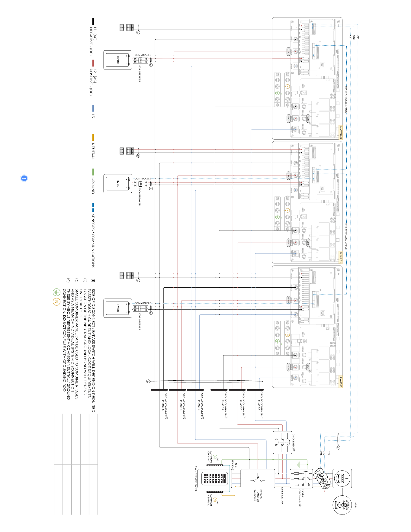
Copyright © 2025 Sol-Ark LLC | SK140-0015-004 63
Diagram 0
8
Before powering up Parallel System installs, please see section 5 “Parallel
Systems”
Sol-Ark 60K-3P-480V
Standard Wiring Diagram
– 3 Parallel Inverters, Standard Wiring
78 kW MAX.
78 kW MAX.
78 kW MAX.
UTILITY METER
277/480V

64 Copyright © 2025 Sol-Ark LLC
8.0 Common Troubleshooting Steps
LCD is not powering on
- Check all connections – at least one of the following power sources is required: PV/Grid/Battery
- Try pressing the power button, touchscreen, or navigation buttons
Panels are connected, but “DC” LED indicator is not on
- Startup voltage is 180V. Voltage must be above 180V and below 1,000V
- Wrong polarity. Check string polarity on MPPT
- PV DC disconnect switches are not on the ON position
Panels are not producing
- Check for proper wiring on all solar panel connections
- Turn PV disconnect switches "ON"
- Check that the PV input voltage is not greater than 1,000V
- If the system measures 0V even when PV DC disconnect is ON, polarity might be wrong. Check PV polarity
Panels are not producing much power
- PV Wire Strip Length: 5/8". Your batteries are charged and is limited to house loads; you can test Grid Sell to verify.
The system does not keep batteries charged
- Verify there is proper communication between the Sol-Ark and the battery. : → Li-Batt Info
- Verify proper Charge and Voltage settings according to battery manufacturer and battery bank arrangement
Auto Gen-Start is not working
- Make sure the generator has a compatible Two-Wire
- Verify adequate connection to the Sol-Ark auto-start input pins
“Normal” LED indicator is not on
- Sol-Ark is in pass-through mode (only Grid connection and no other power source)
- Not fully energized (DC Solar panels AND Grid or batteries only)
- In alarm state.
- Sol-Ark is not working correctly (Call technical support +1 (972) 575-8875 Ext. 2)
The “Alarm” LED indicator is on
- Check the system alarms menu to identify the alarm
Grid HM value is negative when it should be positive (only applies in Limited to Home mode)
- Limiter Sensors are backwards, L1/L2/L3 sensors are swapped, or incorrectly wired. Execute the "Auto Learn Home Limit Sensors"
command described in section 2.9 "Limit Sensors, Automatic CT Limit Sensors Configuration"
AC Overload Fault or Bus Unbalance Fault
- Check Transfer Switch/Subpanel wiring
- Check for large loads that consume more than the inverter rating
The system connects to grid and quickly disconnects
- Verify Neutral wire connection (0Vac referenced to GND)
- Check the programmed frequency, and verify the Sol-Ark measures 277V between L and N
- If the system is overloading: verify that proper phase sequence between “GRID” and “LOAD” terminals

Sol-Ark 60K Installation Guide | SK140-0019-004 65
DC Overload Fault
- Check PV voltage. Ensure no more than 1,000V
- Make sure you have not wired more than two (2) solar strings in parallel per MPPT
System is beeping
- Check the System Alarms menu to see which alarm has been triggered. Most alarms will self-reset
- Do a Power Cycle as described in section 2.12 “Power Cycle Sequence”
Battery cable sparks when connected
- If applicable, flip the built-in breakers of the battery bank before connecting or disconnecting batteries
Battery symbol on the home screen is red
- The battery is below the empty voltage
- Battery is over-voltage or under-voltage
Battery symbol on the home screen is yellow
- The battery is low, or the charge/discharge current is close to the programmed limit
Grid symbol on the home screen is yellow
- Grid parameters are out of specified operating range
- There is a grid outage and there is no voltage on the “GRID” terminal
- System is Off-Grid
System has restarted
- Occurs when the system has overloaded, battery voltage has surpassed 800V
- There was a Software update
Batteries were connected backwards
- System may be damaged and warranty will be void.
Why is the LCD screen still on when the power button is off?
- Occurs when the power button is in the “OFF” position
- Occurs when the system is not fully energized: PV or Grid only
The Batt SOC% is not reaching 100%
- BMS communication is not working properly. Verify with battery integration and communication steps
Generator setup is reading 0Hz
- Generator is operating at a frequency outside the permissible range. Select " General Standard " grid mode. Widen the frequency
range to 55Hz-65Hz as described in section 2.5 “Integrating a Generator”
Color Touchscreen is Frozen
- Press and hold the escape button [◄] for 7-10 seconds
- Perform a power cycle sequence in case the above suggestion does not work. See section 2.12 “Power Cycle Sequence”
Grid Phase Wrong
- If the Sol-Ark screen shows a “Grid Phase Wrong” message, it means there is a phasing issue in the wiring. If left unchecked it
may cause overload faults and DAMAGE. See section 5.3 “Troubleshooting Phase Sequence”
66 Copyright © 2025 Sol-Ark LLC
8.1 Sol-Ark Warning and Fault codes
Fault
Description
Common Cause/Remedy
W03
Grid_Phase_Warn
Grid phasing sequence error. Verify order of the three phases of the GRID input are in
the order ABC, or change the phase setting value on the LCD.
W04
Meter_Offline_Warn
Communication failure with external revenue grade meter. Verify that the meter is
powered on and the RJ45 connection is secure.
W31
BMS_LostComm_Warn
Contact Sol-Art Support.
W32
Parallel_Comm_Warn
The quality of parallel inverter communication is poor. Communication is possible but
there may be packet loss. Verify if the DIP switch of each inverter is set to 'ON'. Check
the length of the parallel communication cables, the length should not be more than
16ft (5m) between inverters.
F1
DC_Inversed_Failure
Verify that the PV input wires are not reverse polarity.
If you have parallel systems and turn one system off, you will get this notification.
F8
GFDI_Relay_Failure
Check for continuity on the inverter's neutral and ground. Ensure there is only ONE
neutral-to-ground bond in the system. Current Leakage from inverter AC output to
Ground, check Ground and neutral are connected at the main panel.
F13
Grid_Mode_change
It can happen when not using batteries or if Grid Input settings are changed. This is a
notification, NOT a fault. If you switch from No Batt to Battery mode, power the system
down completely to restart.
F15
AC_OverCurr_Failure
It is usually caused by Loads too large for the inverter. If Off-Grid, the battery discharge
Amps are programmed too low. Overloads can result in F15, F18, F20, or F26.
F16
GFCI_Failure
Ground fault. Check PV+ or PV- wiring (which must be ungrounded). Exposed PV
conductors + rain can also cause. Check that the neutral line and Ground are not
double-bonded (common with portable generators).
F18
HW_Ac_OverCurr_Fault
Overloaded the Load Output (reduce loads) or overloaded a generator (reduce Gen
Start A). Wiring Short on the AC Side can also cause this error. Overloads can result in
F15, F18, F20, or F26.
F20
Tz_Dc_OverCurr_Fault
It is typically caused by DC current from the battery that is too large (ex: 4 Ton AC Unit)
or too much PV current (3 or more strings in parallel). Overloads can result in F15, F18,
F20, or F26.
F22
Tz_EmergStop_Fault
Initiated emergency stop by opening the B/B circuit. Reset e-stop button (close
contacts) to clear fault.
F24
DC_Insulation_Fault
An exposed PV conductor combined with moisture is faulting (can cause F16, F24, and
F26).
F25
DC_Feedback_Fault
No battery connection to the Inverter and Activate Battery is enabled. Disable Activate
Battery in settings while no battery is connected.
F26
BusUnbalance_Fault
Too much load on one leg (L1 or L2) vs. the other leg or DC loads on the AC output
when Off-Grid. Grounded PV+/- wire can cause F20, F23, or F26.
F29
Parallel_CANBus_Fault
Usually, a communication error for parallel systems. Check cables, and MODBUS
addresses.
F31
AC_SlaveContactor_Fault
Soft Start of the large motor failed.
F34
AC_Overload_Fault
AC Overload or load shorted. Reduce heavy loads.
F35
AC_NoUtility_Fault
Grid connection lost.
F37
DCLLC_Soft_Over_Cur
Software DC overcurrent.
F39
DCLLC_Over_Current
Hardware DC overcurrent.
F40
Batt_Over_Current
Batteries exceeded their current discharge limit.
F41
Parallel_System_Stop_Fault
If one system faults in parallel, this normal fault will register on the other units as they
disconnect from the grid.
F45
AC_UV_OverVolt_Fault
Grid under voltage causes a disconnect. This will self-reset when the grid stabilizes.
F46
Battery_Backup_Fault
Cannot communicate with other parallel systems. Check Master = 1, Slaves = 2-9 and
that ethernet are connected.
F47
AC_OverFreq_Fault
Grid over Frequency (common in power outages) causes disconnect. Will self-reset
when grid stabilizes.
F48
AC_UnderFreq_Fault
Grid under Frequency (common in power outages) causes a disconnect. Will self-reset
when grid stabilizes.

Sol-Ark 60K Installation Guide | SK140-0019-004 67
F50
BAT_V_float
Battery voltage reading fault. This can happen if BMS V reading is too different than
internal reading. Check external breakers and BMS battery relay status.
F52
DC_VoltHigh_Fault
HV bus V is too high. Please reboot inverter and wait to see if fault comes back. Check
PV and Batt V.
F54
BAT2_VoltHigh_Fault
PV may be higher than 500V. Battery voltage should not be above 59V or 63V
(depending on the model).
F55
BAT1_VoltHigh_Fault
Batt Voltage on input 1 is too high. Verify V reading on inverter screen and with meter.
Stop operation and immediately check with the battery manufacturer.
F56
BAT1_VoltLow_Fault
Batteries are overly discharged, the inverter is Off-Grid and exceeded the
programmed batt discharge current by 20%, or Lithium BMS has shut down. If battery
settings are incorrect, this can also happen.
F57
BAT2_VoltLow_Fault
Batt Voltage on input 2 is too low.
Check BMS status and verify readings with a meter and at screen.
F58
BMS_Communication Fault
Sol-Ark is programmed to BMS Lithium Battery Mode but cannot communicate with a
BMS. BMS_Err_Stop is enabled, but cannot communicate with a battery BMS
F59
BAT_OverCurr_Fault
Excessive load is drawing too much current from the battery
The battery voltage is too low for the inverter to operate
F60
Gen_Volt_or_Fre_Fault
Generator Voltage or Frequency went outside the allowable range.
F61
Button_Manual_OFF
The parallel “slave” system turned off without turning off the “master.”
F63
Arc_Fault
It can be a poor PV connector / Connection, or sometimes a false alarm due to
powerful lighting storms.
F64
Heatsink_HighTemp_Fault
Check that the built-in fans are running; the ambient temperature may be too high.
Ensure proper clearances.
68 Copyright © 2025 Sol-Ark LLC
8.2 Warranty Verification Checklist
MUST complete this form AFTER the system is operational. To register the product warranty, this verification checklist
must be filled out and submitted to Sol-Ark. Visit https://www.Sol-Ark.com/register-your-Sol-Ark/ to register warranty.
Installer/Company:___________________________________ Date: (YYYY-MM-DD) __________________________________
Inverter SN: _________________________________________ Gateway SN:_________________________________________
Mark ✓ for all that apply
Indicate the type of system (all that apply):
Grid-Tied only
Grid-Tied with battery backup
Off-Grid
Parallel system: # inverters
Indicate integrated components (all that apply):
Utility grid
DC solar panels
AC coupled solar panels
Generator
“LOAD” installed service panel
“GRID” installed service panel
“GEN” installed service panel
Batteries
Lead-Acid batteries
Wind Turbine
It is strongly recommended to send a Wiring Diagram of the installation to [email protected] for verification, otherwise Sol-Ark
expressly disclaims any responsibility for performance issues arising from improper installation. Installers and users are solely responsible
for following proper installation procedures outlined in provided documentation. Sol-Ark disclaims any liability for changes in the
installation that might result in electrical malfunctions or any other issues related to the Sol-Ark product.
Circle N/A (Not Applicable) if the verification step is not relevant to the type of system or does not apply to the integrated components.
1. A wiring diagram of the installation was sent to Sol-Ark for verification
Y N
2. Setup for remote system monitoring through Wi-Fi / Ethernet is completed. Gateway
SN:_______________________
Y N
3. The inverter is installed in a location where the LCD screen is always protected from direct sunlight
4. The inverter has the minimum specified vertical and lateral clearance for proper heat dissipation
5. The maximum DC input voltage does not surpass 1,000V
DC
6. The HV Battery bank voltage does not surpass 700V
DC
7. All battery conductors are properly connected and secured to the (+, -) terminals of the inverter
N/A
8. Battery communication was successfully established
N/A
9. All Battery Setup parameters are programmed according to battery manufacturer specifications
N/A
10. The Sol-Ark properly generates power from the solar panels to charge the batteries
N/A
11. Grid / Generator is properly connected to the Sol-Ark and the phase sequence was verified
N/A
12. “🗹 Grid / Gen Charge” settings are programmed correctly. Grid / Generator adequately charge the batteries
N/A
13. For Off-Grid systems: The mode “General Standard” is programmed and the V & f ranges are increased
N/A
14. When “🗹 Grid Sell” is enabled, the Sol-Ark sells power back to the grid (negative HM measurements for L1, L2,
L3)
N/A
15. CT sensors are correctly installed on Grid / Generator lines
N/A

Sol-Ark 60K Installation Guide | SK140-0019-004 69
16. Only when “🗹 Limited Power to Home” is enabled, the Sol-Ark matches total load demand (Meter Zero)
N/A
17. Disconnect the grid: during Off-Grid operation, the inverter properly supplies “LOAD” demand for PV and
batteries
N/A
18. Disconnect the grid AND solar panels: during Off-Grid operation, the inverter properly draws power from
batteries
N/A
In the event of system-related issues, forward a comprehensive description of the problem via email to support@Sol-Ark.com. Ensure the
addition of images, including the "Details Screen" with all electrical measurements, as well as images of the inverter, wiring configuration,
user area, batteries, and any other integral components constituting the power system.
______________________________________
______________________________________
______________________________________
Installer name and signature
Customer name and signature
Date

70 Copyright © 2025 Sol-Ark LLC
Copyright © 2024 Sol-Ark LLC | SK150-0051-002
Limited Warranty: Sol-Ark 60K-3P-480V
10-Year Limited Warranty for Sol-Ark LLC Products. Sol-Ark LLC provides a Ten-year (10) limited
Warranty ("Warranty") against defects in materials and workmanship for its Sol-Ark LLC products
("Product"). The term of this warranty begins on the Product(s) initial purchase date, or the date
of receipt of the Product(s) by the end user, whichever is later. This must be indicated on the
invoice, bill of sale from your installer. This warranty applies to the original Sol-Ark LLC Product
purchaser and is transferable only if the Product remains installed in the original use location.
Please call Sol-Ark LLC to let us know if you are selling your Home and give us name and contact
of the new owner.
The warranty does not apply to any Product or Product part that has been modified or damaged by the following:
• Installation or Removal (examples: wrong voltage batteries, connecting batteries backward, damage due to water/rain to
electronics, preventable damage to solar wires.)
• Alteration or Disassembly.
• Normal Wear and Tear.
• Accident or Abuse.
• Unauthorized Firmware updates/software updates or alterations to the software code.
• Corrosion.
• Lightning: unless using EMP hardened system, then Sol-Ark LLC will repair the product.
• Repair or service provided by an unauthorized repair facility.
• Operation or installation contrary to manufacturer product instructions.
• Fire, Floods, or Acts of Nature.
• Shipping or Transportation.
• Incidental or consequential damage caused by other components of the power system.
• Any product whose serial number has been altered, defaced, or removed.
• Any other event not foreseeable by Sol-Ark LLC
Sol-Ark LLC liability for any defective Product, or any Product part, shall be limited to the repair or replacement of the Product, at Sol-Ark
LLC discretion. Sol-Ark LLC does not warrant or guarantee workmanship performed by any person or firm installing its Products. This warranty
does not cover the costs of installation, removal, shipping (except as described below), or reinstallation of Products or parts of Products. LCD
screen and fans are covered for 5 years from date of purchase.
THIS LIMITED WARRANTY IS THE EXCLUSIVE WARRANTY APPLICABLE TO SOL-ARK LLC PRODUCTS. SOL-ARK LLC EXPRESSLY DISCLAIMS
ANY OTHER EXPRESS OR IMPLIED WARRANTIES OF ITS PRODUCTS. SOL-ARK LLC ALSO EXPRESSLY LIMITS ITS LIABILITY IN THE EVENT
OF A PRODUCT DEFECT TO REPAIR OR REPLACEMENT IN ACCORDANCE WITH THE TERMS OF THIS LIMITED WARRANTY AND
EXCLUDES ALL LIABILITY FOR INCIDENTAL OR CONSEQUENTIAL DAMAGES, INCLUDING WITHOUT LIMITATION ANY LIABILITY FOR
PRODUCTS NOT BEING AVAILABLE FOR USE OR LOST REVENUES OR PROFITS, EVEN IF IT IS MADE AWARE OF SUCH POTENTIAL
DAMAGES.
Return Policy - No returns will be accepted without prior authorization and must include the Return Material Authorization (RMA) number.
Please call and talk to one of our engineers to obtain this number at 972-575-8875.
Return Material Authorization (RMA) A request for an RMA number requires all the following information: 1. Product model and serial
number; 2. Proof-of-purchase in the form of a copy of the original Product purchase invoice or receipt confirming the Product model number
and serial number; 3. Description of the problem; 4. Validation of problem by Technical Support, and 5. Shipping address for the repaired
or replacement equipment. Upon receiving this information, the Sol-Ark LLC representative can issue an RMA number. Any product that is
returned must be brand new, in excellent condition and packaged in the original manufacturer's carton with all corresponding hardware
and documentation. Returns must be shipped with prepaid freight and insured via the carrier of your choice to arrive back at Sol-Ark LLC
within 30 days of your initial delivery or pick-up. Shipping charges will not be refunded. All returns are subject to a 35% restocking fee. No
returns will be accepted beyond 30 days of original delivery. The value and cost of replacing any items missing (parts, manuals, etc.) will be
deducted from the refund. If you have any questions regarding our return policy, please email us at [email protected] or call us at the
number above during regular (Monday to Friday) business hours.
Sol-Ark 60K-3P-480V Install Operational Verification Checklist Questionnaire must be filled out, signed, and dated to secure full warranty
coverage.
Contact: (USA) +1-972-575-8875
For Info/Purchasing:
[email protected]om | ext.1
For Tech Support/Warranty Claim:
support@sol-ark.com | ext.2
For Administrative Help | ext.3
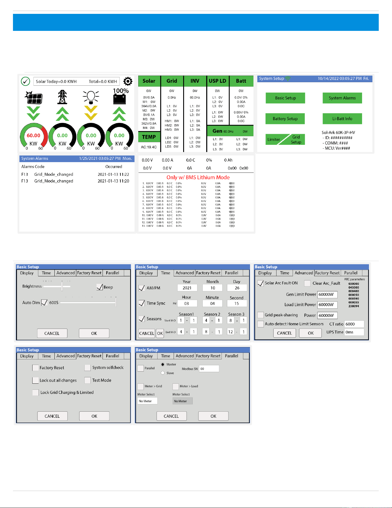
Sol-Ark 60K Installation Guide | SK140-0019-004 71
8.3 Inverter UI Screens
.The user interface (UI) screens shown in the following pages represent the version of the Sol-Ark inverter firmware as of the Effective Date.
Sol-Ark continually improves its products through firmware updates, which may alter the appearance, layout, or functionality of the UI
screens. Sol-Ark does not warranty performance if you fail to update or use the most recent version of Sol-Ark software.
1. Main Menu
2. Basic Setup
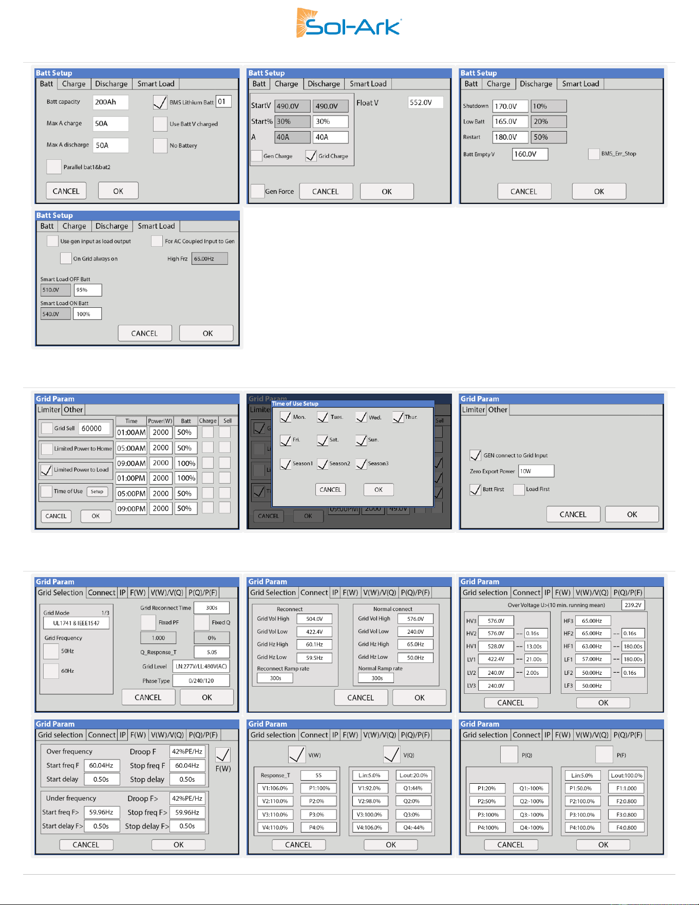
72 Copyright © 2025 Sol-Ark LLC
3. Batt Setup
4. Limiter
5. Grid Setup

Sol-Ark 60K Installation Guide | SK140-0019-004 73