enfr
RollUp S Art. 18604
RollUp M Art. 18614
18604-80.960.01/0124
en Operator‘s manual
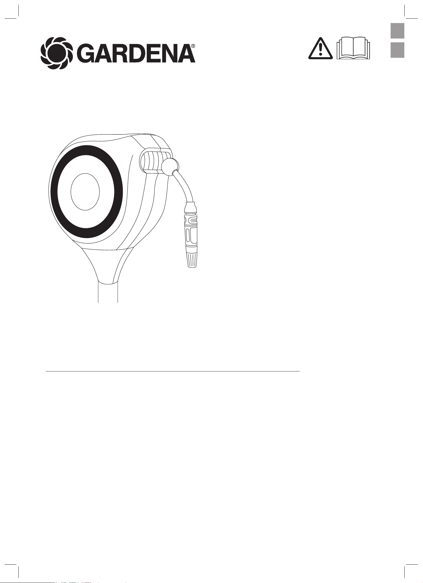
Garden Hose Box
fr Manuel d‘utilisation
Dévidoir automatique sur pic
2
A
1x
B1x
C1x
D 1x E 1x F 1x G 1x H 2x I 3x
K1x
L1x M 3x
J1x
A 1x + B 1x + C
C
I
1x + I 3x
G
A
3
G 1x
4
F 1x +G 1x
F 1x +G 1x
3
1.
3.
2.
E
5
6 7
8
D
F
A
H
or
L
J
M
N
A 1x +D 1x + E 1xH 2x
J 1x +L 1x +L 1x +M 1x or N 1xM 1x + N 1x
4
en
3. ASSEMBLY
WARNING!
Risk of suocation.
Small parts can be easily swallowed. Toddlers can suocate on the
polybag.
Æ Keep toddlers away when you assemble the product.
3.1. Preparation
Prepare the following tool:
Æ A hand-operated Phillips screwdriver.
3.2. Choosing a mounting location
Æ Choose a mounting location that is near an outdoor faucet.
Æ Choose a mounting location that prevents water from entering the buil-
ding in the event of a leak.
Æ Choose a mounting location that is protected against direct sunlight so
that the product, the hose and the water won’t overheat.
Æ Choose a mounting location where no electrical cables or other lines
can be drilled into.
Æ Choose a solid, stable and at area of grass and soil that ensures the
hose box won’t tip over.
Æ Choose a solid area of grass and soil in your private garden.
Æ Make sure that there are no loose stones or sand underneath the area.
Æ Check the stability of the area to ensure it is strong enough to support
the weight of the hose box.
Æ If you have any questions about mounting, please contact the
GARDENA service team.
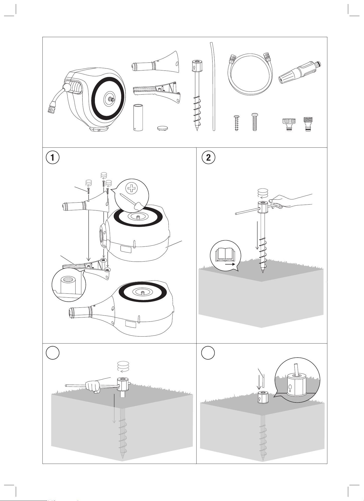
3.3. Fitting the half shells onto the hose box [Fig. 1]
1. Place the hose box A at on a stable and clean surface, ensuring that it
is secure and cannot roll away.
2. Insert the two half shells B and C into the round brackets on the hose
box.
3. Use the three screws I provided and insert them into the designated
screw drill holes on the half shell B.
4. Use a Phillips screwdriver to tighten the screws, securing the half shell
B to the half shell C.
5. Make sure that the half shells B and C are securely attached to the
hose box A and do not slip o.
6. Tighten the three screws I.
The half shells B and C are tted.
3.4. Inserting the earth spike into the ground [Fig. 2–4]
3.4.1 Attaching the lever G to the earth spike F [Fig. 2]
1. Guide the lever G with the straight side pointing forward through the
opening on the side of the head of the earth spike F.
2. Stop the movement when the curved side of the lever G reaches its
end.
3.4.2 Drilling the earth spike F into the ground [Fig. 3]
WARNING!
Electric shock.
Injuries caused by drilling into power cables.
Æ Make sure that there are no electrical cables or other lines under
the ground before drilling into the ground.
1. Place the earth spike F with the tip facing forward onto the ground.
2. Hold the lever G at the outer end of its straight side to prevent your
hand from getting caught between the earth spike F and the lever G.
3. Use the lever G as a handle to drill the earth spike F clockwise into the
ground.
4. Stop the movement when only the head of the earth spike F is visible.
The earth spike F is drilled into the ground.
5. Guide the lever G with the straight side pointing forward through the
opening on top of the head of the earth spike F.
6. Stop the movement when the curved side of the lever G reaches its
end.
en Garden Hose Box
Original instructions
1. SCOPE OF DELIVERY
A Hose box E Lid for the sleeve H STS screw 40x16
B Half shell F Earth spike J Connection hose
C Half shell G Lever K Nozzle
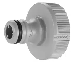
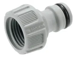
D Metal sleeve H STS screw 40x16 L Tap connector
M Accessories adapter
2. SAFETY INSTRUCTIONS
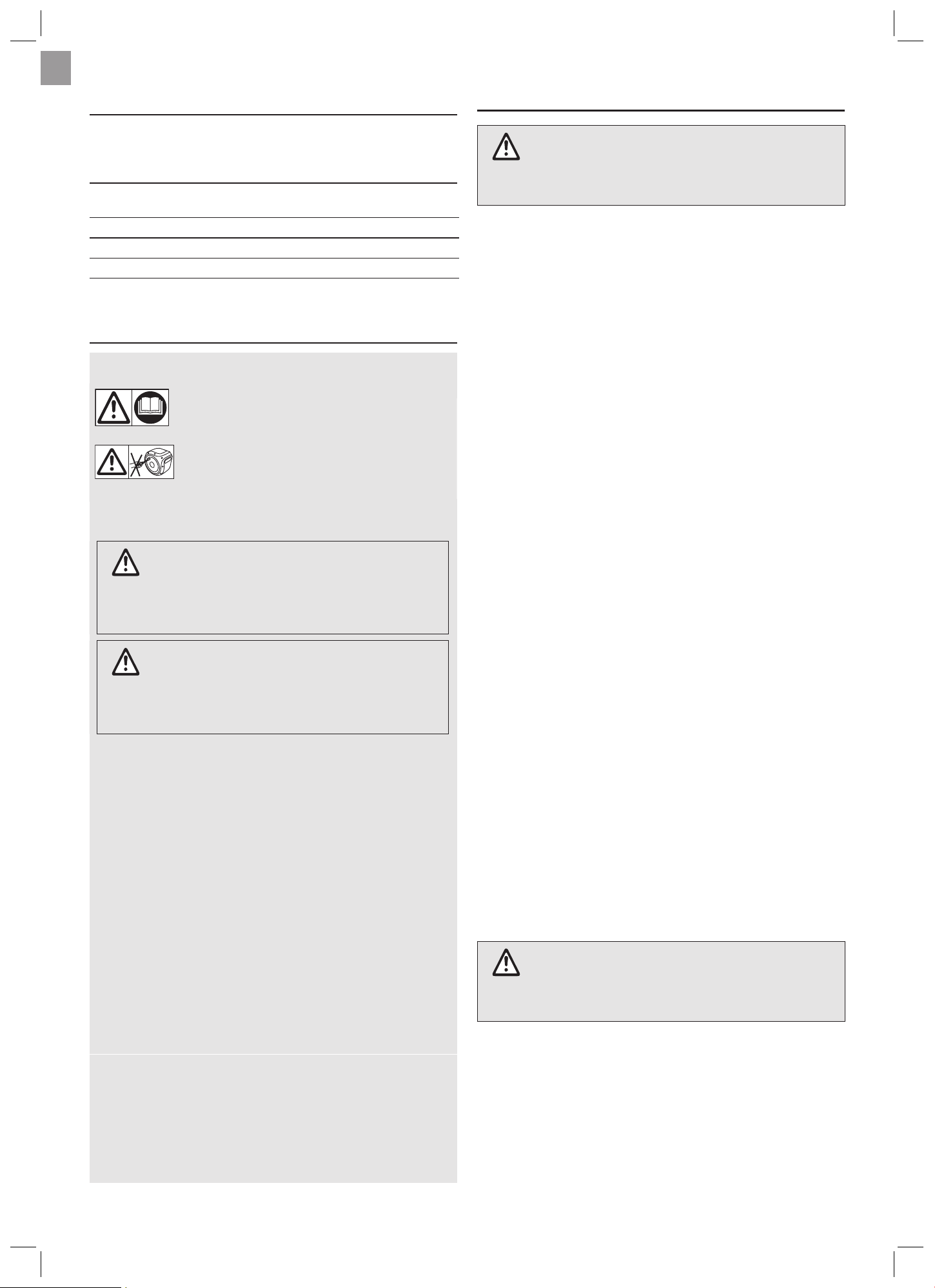
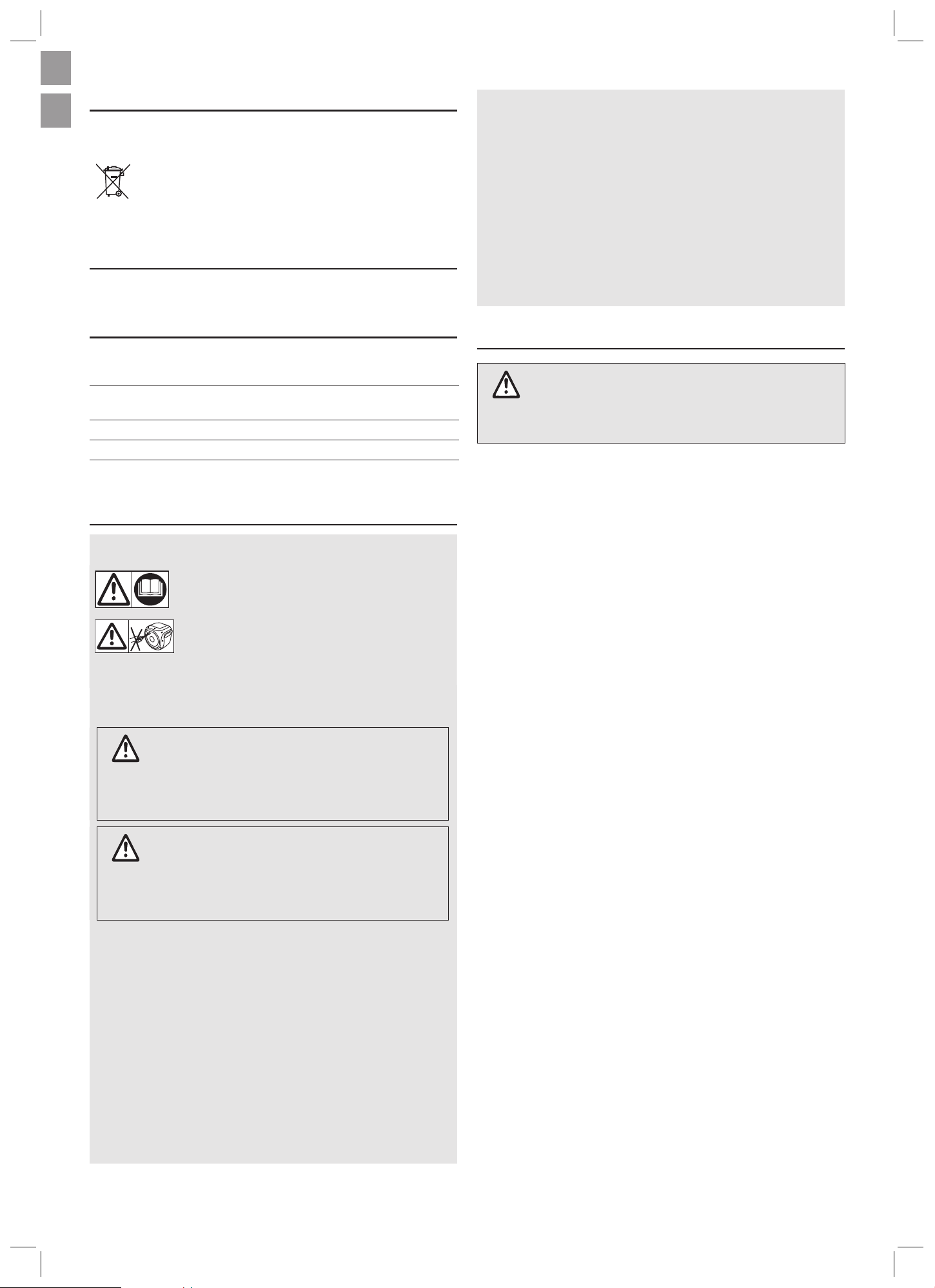
2.1. Explanation of the symbols on the product
CAUTION!
Read the operating instructions before initial ope-
ration.
WARNING!
Physical injury through prestressed springs.
The hose box may not be opened.
2.2. Explanation of the safety warnings
CAUTION!
Indicates a hazardous situation that, if not avoided, could result in
minor or moderate injury.
Æ Follow the instructions of the safety warning to prevent the
threat.
WARNING!
Indicates a hazardous situation that, if not avoided, could result in
death or serious injuries.
Æ Follow the instructions of the safety warning to prevent the
threat.
2.3. General safety instructions
ÆRead the operator’s manual carefully before use and keep for future
reference.
ÆNever operate the product when you are tired, ill or under the inuence
of alcohol, drugs or medicine.
ÆThis product contains springs that are under tension and could result
in injury if the product is operated by someone who is: unfamiliar with
this product, needs adult supervision, or has impaired judgment due
to fatigue, medication, or other substances that can impair judgment
or coordination.
ÆChildren must be supervised to ensure that they do not play with the
product.
ÆNever drink the water from the hose.
ÆNever use hot water with this product.
ÆDo not place any additional load onto the earth spike F.
ÆDepressurize the hose when not in use.
ÆRegularly inspect the earth spike F for signs of wear and tear.
ÆDo not use the hose box and earth spike F to hang objects such as
hammocks.
ÆUse the adapter M only with nozzles, designed for gardening.
2.4. Intended use
The hose box is intended for use with cold water for outdoor irrigation
only.
The hose is not intended to be used as a drinking water hose.
The earth spike F is suitable for use with the hose box only.
The product is intended exclusively for use in private household gar-
dens or on private allotments.
5
en
4.3. Retracting the hose
CAUTION!
Risk of injury due to uncontrolled hose feed.
Æ Do not allow the hose to be retracted without supervision.
Æ Keep people and animals away from the hose feed.
1. Release the locking device by pulling briey on the hose.
2. Hold the end of the hose rmly and walk the hose back to the box with
the nozzle K.
The hose rolls up securely and evenly on its own.
The locking mechanism clicks during unwinding and retraction.
5. DISASSEMBLY
5.1. Removing the hose box from the earth spike F [Fig. 7]
1. Ensure you have a secure footing and carry the hose box as close to
your body as possible.
2. Pull the hose box A out of the metal sleeve D with both hands.
3. Push the lid E onto the open end of the metal sleeve D.
6. TRANSPORTATION AND STORAGE
The hose box is not frost-proof.
Æ Disconnect the hose box A from the faucet when it is not in use for
long periods of time.
Æ Remove the hose box from the earth spike F in winter to prevent frost
damage.
6.1. How to transport and store the hose box
Æ Empty the hose before transporting it.
Æ Store the hose box in a location that is out of the reach of children.
7. ACCESSORIES AND SPARE PARTS
Half shell Art. 18604-00.600.01
Half shell with threads Art. 18604-00.610.01
Earth spike Art. 18604-00.620.00
Lid for the sleeve Art. 18604-00.600.12
Metal sleeve Art. 18604-00.600.06
Lever Art. 18604-00.600.11
Tap connector L Art. 18220-20/Art. 18221-20/
Art. 18222-20
Accessories connector M GA110-0099
8. TECHNICAL DATA
18604 18614
Hose length 50 ft/15 m 65 ft/20 m
Weight 14.1 lbs/6.4 kg 16.3 lbs/7.4 kg
9. SERVICE / WARRANTY
9.1. Product registration
Please register your product at gardena.com/registration.
9.2. Service
Please nd the current contact information of our service on the back page
and online:
• USA: https://us.gardena.com/pages/contact-1
• Canada: https://www.gardena.com/ca-en/support/advice/contact/
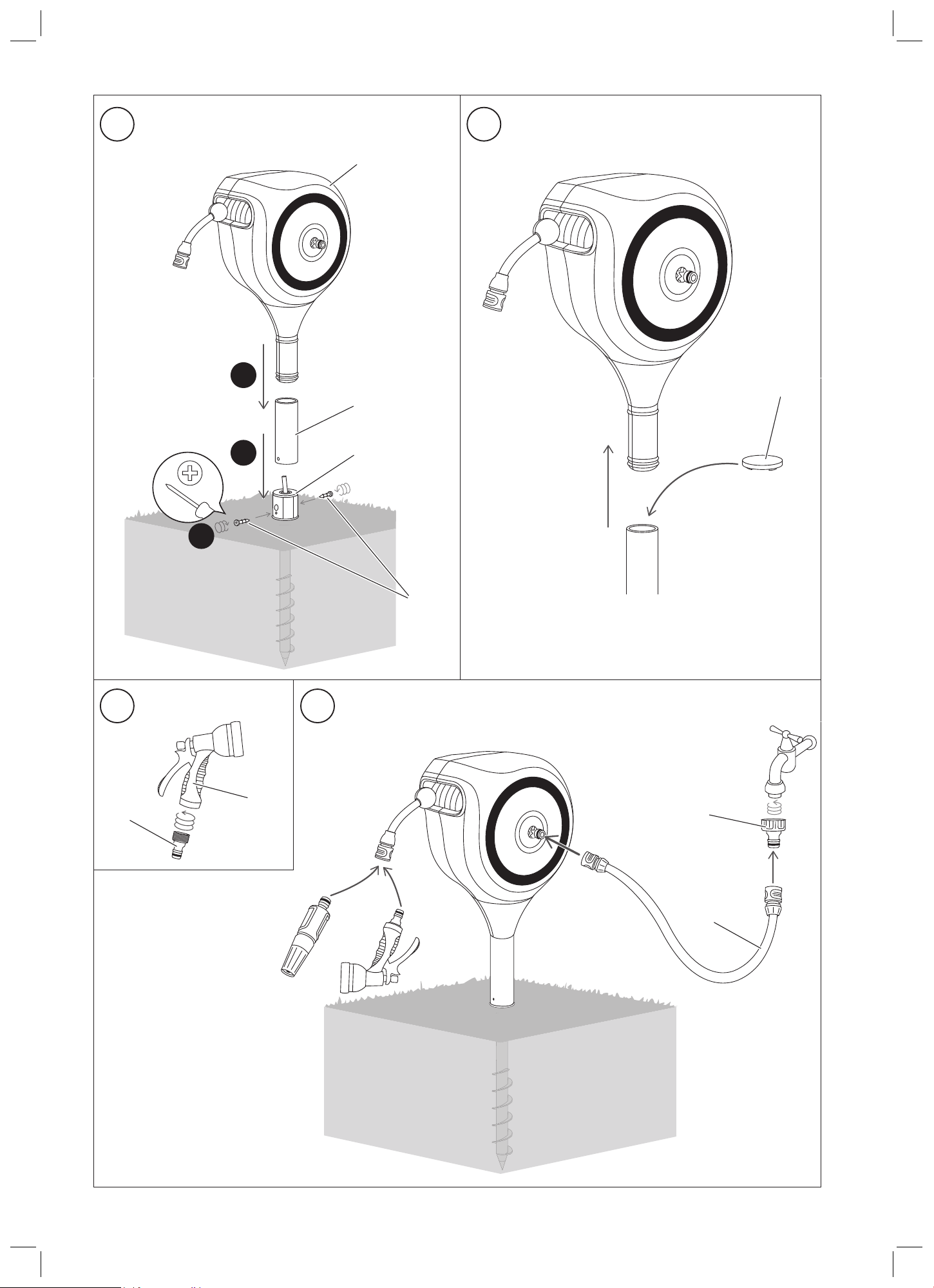
3.5. Fitting the hose box onto the earth spike [Fig. 5]
CAUTION!
Risk of crushing between the product and the earth
spike!
The product is heavy. Body parts between the hose box and the earth
spike can be injured.
Æ Do not reach between the product and the holder.
Æ If necessary, ask for help to carry the product.
3.5.1 Fitting the metal sleeve onto the earth spike [Fig. 5]
1. Guide the metal sleeve D carefully onto the earth spike F until the metal
sleeve D hits the ground.
2. Align the holes on the side of the metal sleeve D with the holes on the
side of the head of the earth spike F.
3. Insert the two screws H into the designated openings of both the metal
sleeve D and the earth spike F.
4. Use a Phillips screwdriver to tighten the screws H.
3.5.2 Fitting the hose box A to the metal sleeve F [Fig. 5]
1. Ensure you have a secure footing and carry the hose box as close to
your body as possible.
2. Push the hose box A into the metal sleeve D with both hands.
3.6. Assembling your own nozzle N [Fig. 6]
With the accessories adapter M you can attach every nozzle with an inner
thread to the hose.
Æ Drill the accessories adpater M clockwise into the inner thread of your
own nozzle N.
The combination of M and N can be attached to the hose.
3.7. Connecting the hose box A to the faucet [Fig. 7]
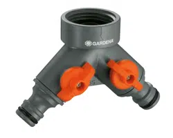
1. Twist the tap connector L onto the faucet.
2. Connect one end of the connection hose J to the tap connector L.
3. Push the other end of the connection hose J onto the connector on the
side of the hose box A.
The hose box A is connected to the faucet.
4. Push the nozzle into the connector on the hose.
5. Carefully open the faucet and make sure that the water only comes out
of the nozzle.
The hose box A is ready for use.
4. OPERATION
CAUTION!
Crushing and entanglement hazard due to high spring
force.
Æ Keep your ngers, hair, clothing and all other objects away from the
hose and inlet shaft!
Æ Keep children away from the product.
This product is not a toy and children should not be allowed to play with
or use the hose box.
4.1. Preparation
CAUTION!
Risk of scalding due to heated water from the hose.
The water in the hose may heat up in strong sunlight.
Æ Carefully check the temperature of the water. Do not spray people
with the water.
Æ Check the product for damage before retracting and unwinding.
Æ Do not use a damaged product.
Æ Keep people and animals away from the product while it is in use.
4.2. Unwinding the hose
Æ Pull out the hose to desired length.
Æ The hose can be locked at intervals of approximately 25–45 cm.
6
fr
10. DISPOSAL
Disposal of the hose box
The product must not be disposed of together with
normal household waste. It must be disposed of in
line with local environmental regulations.
fr Dévidoir automatique sur pic
Traduction des instructions originales.
1. SONT COMPRIS DANS LA LIVRAISON
A Dévidoir E Couvercle du man-
chon
I Vis M5x25
B Demi-coque F Piquet de terre J Tuyau de raccor-
dement
C Demi-coque G Levier K Buse
D Manchon en métal H Vis STS 40x16 L Nez de robinet
M Adaptateur d‘accessoires
2. CONSIGNES DE SÉCURITÉ
2.1. Explication des symboles gurant sur le produit
ATTENTION!
Lisez les instructions avant la première utilisation.
AVERTISSEMENT!
Risques de blessures physiques par des ressorts pré-
contraints.
Ne pas ouvrir le dévidoir.
2.2. Explication des avertissements de sécurité
ATTENTION !
Indique une situation dangereuse qui, si elle n‘est pas évitée, peut
entraîner des blessures mineures ou modérées.
Æ Suivez les instructions de l‘avertissement de sécurité pour éviter
la menace.
AVERTISSEMENT !
Indique une situation dangereuse qui, si elle n‘est pas évitée, peut
entraîner la mort ou des blessures graves.
Æ Suivez les instructions de l‘avertissement de sécurité pour éviter
la menace.
2.3. Instructions générales de sécurité
ÆLisez attentivement ce manuel avant toute utilisation et conservez-le
pour vous y reporter ultérieurement.
ÆN'utilisez jamais le produit si vous êtes fatigué ou malade, ou si vous
êtes sous l'emprise de l'alcool, de drogues ou de médicaments.
ÆCe produit contient des ressorts sous tension qui peuvent provoquer
des blessures s'il est utilisé par une personne qui n'est pas familiarisée
avec ce produit, qui a besoin de la surveillance d'un adulte ou dont le
jugement est altéré par la fatigue, des médicaments ou d'autres sub-
stances susceptibles d'altérer le jugement ou la coordination.
ÆIl convient de surveiller les enfants et de les empêcher de jouer avec le
produit.Ne buvez jamais l'eau du tuyau.
ÆN'utilisez jamais d'eau chaude avec ce produit.
ÆNe placez aucune charge supplémentaire sur le piquet de terreF.
ÆDépressurisez le tuyau s'il n'est pas utilisé.
ÆInspectez régulièrement le piquet de terreF pour vérier qu'il ne pré-
sente pas de signes d'usure.
ÆN‘utilisez l‘adaptateur M qu‘avec des buses conçues pour le jardinage.
2.4. N'utilisez pas le dévidoir et le piquet de terreF pour
suspendre des objets tels que des hamacs.Utilisation
prévue
Le dévidoir est destiné à être utilisé avec de l'eau froide pour l'arrosage
extérieur uniquement.Le tuyau n'est pas conçu pour être utilisé comme
tuyau d'eau potable.
Le piquet de terreF est uniquement adapté à une utilisation avec le
dévidoir.
Le produit est exclusivement destiné à une utilisation dans les jardins
privés et familiaux.
3. MONTAGE
AVERTISSEMENT!
Risque d'étouement.
Les pièces de petites dimensions peuvent être avalées facilement. Les
jeunes enfants peuvent s'étouer avec le sachet en plastique.
Æ Éloignez les jeunes enfants lors du montage du produit.
3.1. Préparation
Préparez l'outil suivant:
Æ Un tournevis cruciforme manuel.
3.2. Choix d'un emplacement de montage
Æ Choisissez un emplacement de montage proche d'un robinet extérie-
ur.
Æ Choisissez un emplacement de montage qui empêche la pénétration
dans le bâtiment d'eau en cas de fuite.
Æ Choisissez un emplacement de montage protégé de la lumière directe
du soleil an que le produit, le tuyau et l'eau ne surchauent pas.
Æ Choisissez un emplacement de montage où aucun câble électrique ou
autre ligne ne peut être percé.
Æ Choisissez une surface d'herbe et de terre solide, stable et plane qui
empêche le dévidoir de se renverser.
Æ Choisissez une surface d'herbe et de terre solide dans votre jardin
privé.
Æ Assurez-vous qu'il n'y a pas de pierres ou de sable sous la surface.
Æ Vériez la stabilité de la zone pour vous assurer qu'elle est susam-
ment solide pour supporter le poids du dévidoir.
Æ Pour toute question relative au montage, contactez l'équipe du service
GARDENA.
3.3. Montage des demi-coques sur le dévidoir [Fig.1]
1. Placez le dévidoirA à plat sur une surface stable et propre, en veillant à
ce qu'il soit bien immobilisé et ne puisse pas rouler.
2. Insérez les deuxdemi-coquesB et C dans les supports ronds du dévi-
doir.
3. Utilisez les trois visI fournies et les insérer dans les trous prévus à cet
eet sur la demi-coqueB.
4. Utilisez un tournevis cruciforme pour serrer les vis xant la demi-coquil-
leB à la demi-coqueC.
5. Assurez-vous que les demi-coquesB et C sont solidement xées au
dévidoirA et ne glissent pas.
6. Serrez les troisvisI.
Les demi-coquesB et C sont montées.
3.4. Insertion du piquet de terre dans le sol [Fig.2–4]
3.4.1 Fixation du levierG au piquet de terreF [Fig.2]
1. Guidez le levierG avec le côté droit orienté vers l'avant à travers l'ou-
verture située sur le côté de la tête du piquet de terreF.
2. Arrêtez le mouvement lorsque le côté courbé du levierG atteint sa
butée.
en
7
fr
4. UTILISATION
ATTENTION!
Risque d'écrasement et d'enchevêtrement en raison de
la force élevée du ressort.
Æ Tenez vos doigts, vos cheveux, vos vêtements et tout autre objet
à l'écart du tuyau et du compartiment de rangement! Tenez les
enfants à distance du produit.
Ce produit n'est pas un jouet. Les enfants ne doivent pas jouer avec le
dévidoir ni l'utiliser.
4.1. Préparation
ATTENTION!
Risque de brûlure en raison de l'eau chaude provenant
du tuyau.
L'eau contenue dans le tuyau peut chauer en plein soleil.
Æ Vériez avec précaution la température de l'eau. N'arrosez pas les
personnes.
Æ Vériez la présence de dommages sur le produit avant d'enrouler et de
dérouler le tuyau.
Æ N'utilisez pas un produit endommagé.
Æ Tenez les personnes et les animaux à l'écart du produit pendant l'utili-
sation.
4.2. Déroulement du tuyau
Æ Déroulez le tuyau de façon à obtenir la longueur souhaitée.
Æ Le tuyau peut être verrouillé à des intervalles d'environ 25 à 45cm.
4.3. Enroulement du tuyau
ATTENTION!
Risque de blessure dû à un déroulement/enroulement
incontrôlé du tuyau.
Æ Ne laissez pas le tuyau s'enrouler sans surveillance. Tenez les per-
sonnes et les animaux à l'écart du déroulement/de l'enroulement
du tuyau.
1. Débloquez le dispositif de verrouillage en tirant brièvement sur le tuyau.
2. Tenez fermement l'extrémité du tuyau et replacez le tuyau dans le dévi-
doir avec la buseK.
Le tuyau s'enroule de lui-même de manière sûre et régulière.Le méca-
nisme de verrouillage s'enclenche lors de l'enroulement et du déroule-
ment.
5. DÉMONTAGE
1. Dépose du dévidoir du piquet de terreF [Fig.7]Assurez-vous d'être
dans une position stable et portez le dévidoir aussi près que possible
de votre corps.
2. Tirez le dévidoirA hors du manchon en métalD avec les deuxmains.
3. Poussez le couvercleE sur l'extrémité ouverte du manchon en métalD.
6. TRANSPORT ET REMISAGE
Le dévidoir n'est pas résistant au gel.
Æ Débranchez le dévidoirA du robinet lorsqu'il n'est pas utilisé pendant
une période prolongée.
Æ En hiver, retirez le dévidoir du piquet de terreF pour éviter les domma-
ges causés par le gel.
6.1. Comment transporter et entreposer le dévidoir
Æ Videz le tuyau avant de le transporter.
Æ Entreposez le dévidoir dans un endroit hors de portée des enfants.
3.4.2 Enfoncement du piquet de terreF dans le sol [Fig.3]
AVERTISSEMENT!
Décharge électrique.
Blessures causées par le perçage dans des câbles d'alimentation.
Æ Assurez-vous qu'il n'y a pas de câbles électriques ou d'autres lig-
nes sous le sol avant de percer dans le sol.
1. Placez le piquet de terreF avec la pointe orientée vers le sol.
2. Maintenez le levierG à l'extrémité extérieure de son côté droit pour évi-
ter que votre main ne se coince entre le piquet de terreF et le levierG.
3. Utilisez le levierG comme poignée pour enfoncer le piquet de terreF
dans le sol en le tournant dans le sens des aiguilles d'une montre.
4. Arrêtez le mouvement lorsque seule la tête du piquet de terreF est
visible.
Le piquet de terreF est enfoncé dans le sol.
5. Guidez le levierG avec le côté droit orienté vers l'avant à travers l'ou-
verture située sur le dessus de la tête du piquet de terreF.
6. Arrêtez le mouvement lorsque le côté courbé du levierG atteint sa
butée.
3.5. Montage du dévidoir sur le piquet de terre [Fig.5]
ATTENTION!
Risque d'écrasement entre le produit et le piquet de
terre!
Ce produit est lourd. Vous pouvez vous blesser sur les parties du
corps situées entre le dévidoir et le piquet de terre.
Æ Ne passez pas la main entre le produit et le support. Si nécessaire,
demandez de l'aide pour porter le produit.
3.5.1 Montage du manchon en métal sur le piquet de terre
[Fig.5]
1. Guidez avec précaution le manchon en métalD sur le piquet de terreF
jusqu'à ce que le manchon en métalD touche le sol.
2. Alignez les trous situés sur le côté du manchon en métalD avec les
trous situés sur le côté de la tête du piquet de terreF.
3. Insérez les deuxvisH dans les ouvertures désignées du manchon en
métalD et du piquet de terreF.
4. Utilisez un tournevis cruciforme pour serrer les visH.
3.5.2 Montage du dévidoirA sur le manchon en métalF [Fig.5]
1. Assurez-vous d'être dans une position stable et portez le dévidoir aussi
près que possible de votre corps.
2. Poussez le dévidoirA dans le manchon en métalD avec les
deuxmains.
3.6. Assemblage de votre propre buse N [Fig. 6]
L‘adaptateur d‘accessoires M permet de xer toutes les buses à letage
intérieur au tuyau.
Æ Percez l‘adaptateur d‘accessoires M dans le sens des aiguilles d‘une
montre dans le letage intérieur de votre buse N.
La combinaison de M et N peut être xée au tuyau.
3.7. Raccordement du dévidoirA au robinet [Fig.7]
1. Vissez le nez de robinetL sur le robinet.
2. Raccordez l'une des extrémités du tuyau de raccordementJ au nez de
robinetL.
3. Poussez l'autre extrémité du tuyau de raccordementJ sur le raccord
sur le côté du dévidoirA.
Le dévidoir est raccordé au robinet.
4. Poussez la busedans le raccord du tuyau.
5. Ouvrez le robinet avec précaution et assurez-vous que l'eau s'écoule
uniquement de la buse.
Le dévidoirA est prêt à l'emploi.
8
fr
10. MISE AU REBUT
10.1. Mise au rebut de la cisaille à batterie
Le produit ne doit pas être jeté avec les ordures
ménagères. Il doit être mis au rebut conformément
aux prescriptions locales de protection de l'environne-
ment en vigueur.
IMPORTANT!
Æ Mettez le produit au rebut par le biais de votre point de collecte et de
recyclage local.
10.2. Mise au rebut du dévidoir
1. Videz le tuyau complètement avant de mettre le dévidoir au rebut.
2. Mettez le produit au rebut par le biais de votre point de collecte et de
recyclage local.
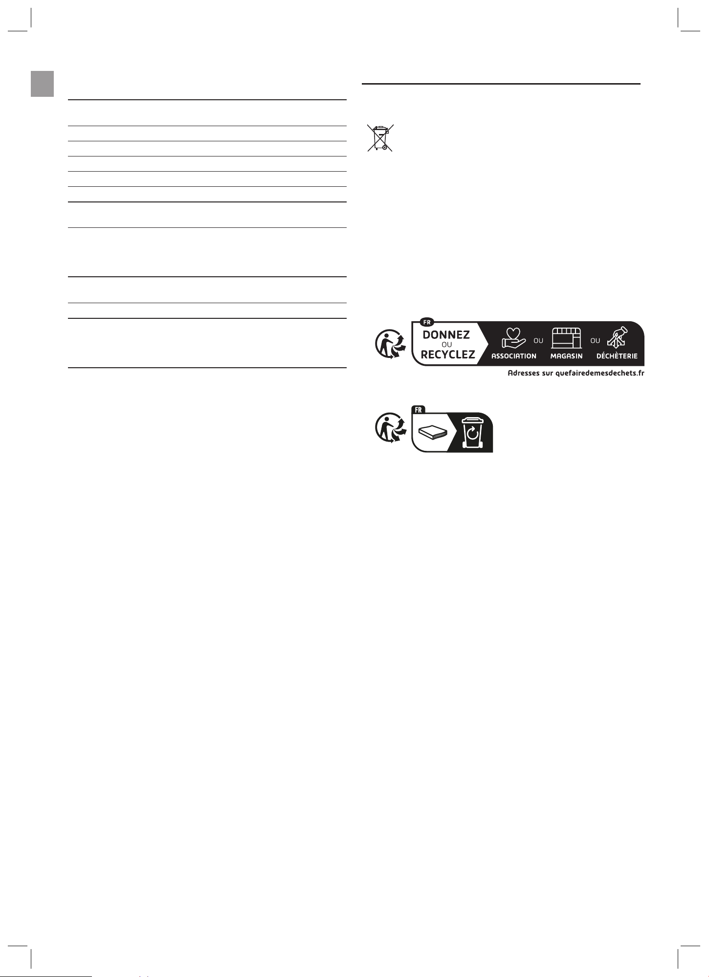
10.3. Mise au rebut en France
Ces instructions sont valables pour la France uniquement.
Æ Mettez le produit au rebut selon les consignes du Triman:
Æ Jetez la version papier du manuel d'utilisation dans le bac de tri:
7. ACCESSOIRES ET PIÈCES DE
RECHANGE
Demi-coque Réf.18604-00.600.01
Demi-coque avec letages Réf.18604-00.610.01
Piquet de terre Réf.18604-00.620.00
Couvercle du manchon Réf.18604-00.600.12
Manchon en métal Réf.18604-00.600.06
Levier Réf.18604-00.600.11
Nez de robinet L Réf.18220-20/Réf. 18221-20/
Réf.18222-20
Adaptateur d‘accessoires M GA110-0099
8. CARACTÉRISTIQUES TECHNIQUES
18604 18614
Longueur du tuyau 50ft/15m 65ft/20m
Poids 14,1lbs/6,4kg 16,3lbs/7,4kg
9. GARANTIE / SERVICE APRÈS-VENTE
9.1. Enregistrement du produit
Enregistrez votre produit sur gardena.com/registration.
9.2. Service après-vente
Vous trouverez les coordonnées actuelles de notre service après-vente à la
n de ce document ainsi qu'en ligne:
• France: https://www.gardena.com/fr/c/assistance/contact
• Belgique: https://www.gardena.com/be-fr/c/assistance/contact
• Canada: https://www.gardena.com/ca-fr/assistance/assistance/con-
tact/
• Luxembourg: https://www.gardena.com/de/service/service-lu/
• Suisse: https://www.gardena.com/ch-fr/assistance/conseils/contact/
• Autres pays: https://www.gardena.com/int/support/advice/contact/

9

10
18604-80.960.01/0124
© GARDENA Manufacturing GmbH
D-89079 Ulm
https://www.gardena.com
Service contact for Canada
GARDENA Canada Ltd.
Member Husqvarna Group
100 Summerlea Rd.
Brampton ON Canada
L6T 4X3
Phone: 905-792-9330
info@gardenacanada.com
Service contact for USA
Gardena Inc.
845 N OVERLAND RD
NORTH SALT LAKE, UT 84054
Phone: 1 (800) 818-8123
servicegardena.us@husqvarnagroup.com