REV-F DATE: 01/10/25 21-33895 OASIS REF SELF-SERVICE B BN C CN-EN
READ AND SAVE THESE INSTRUCTIONS
Important!
See Counter
Installation Guide
Section In This
Manual Before
Proceeding With
Installation!
SELF-SERVICE REFRIGERATED MERCHANDISERS
USER MANUAL
21-33895
OASIS
®
Structural Concepts Corp. ∙ 888 E. Porter Rd ∙ Muskegon, MI 49441 Phone: 231.798.8888 Fax: 231.798.4960 ∙ www.structuralconcepts.com
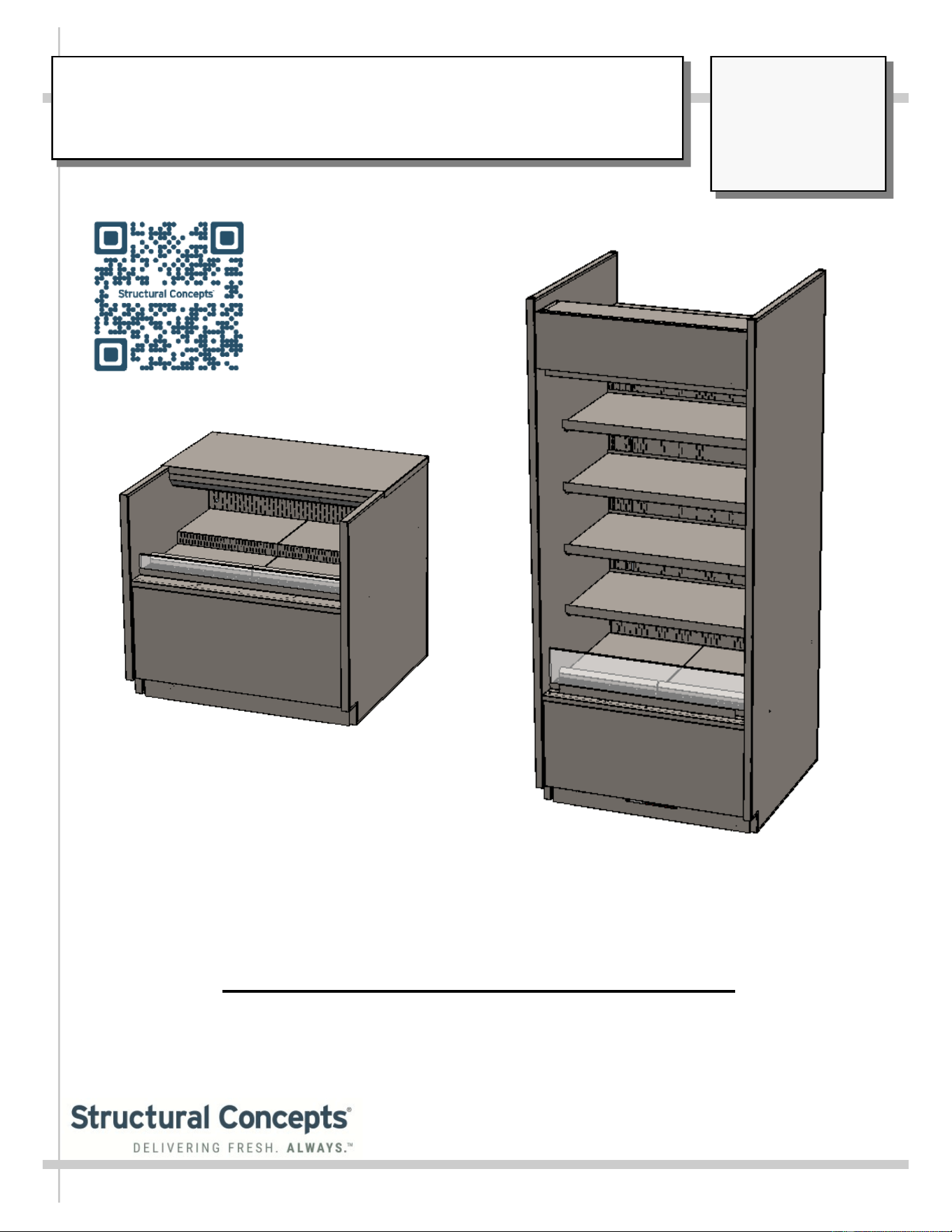
Model B37R
Model C33R
Models Represented In This Operating Manual*
C33R, C43R, C53R, CN33R, CN43R, CN53R, B37R, B47R, B57R, B67R, BN37R, BN47R,
BN47R.8128, BN47R.8128A, BN57R, B35R, B45R, B55R, B65R
* This Manual May Also Be Applicable To Models Not Listed Herein.
TABLE OF CONTENTS
2
TABLE OF CONTENTS ………………………………………………………………………………………..
OVERVIEW / TYPE / COMPLIANCE / WARNINGS / PRECAUTIONS / WIRING / PLUGS ……....…..
SHIPPING BRACKET REMOVAL / TOE-KICK REMOVAL / REMOVAL FROM SKID / CASE
ALIGNMENT …………………………………………………………………………………….………
SHIMMING FRAME SUPPORT RAILS / ADJUSTING LEVELERS ………………………………………
LOAD LEVEL & TEMPERATURE GUIDE .………………………………………………………………….
SHELF AND DECK LOAD LIMITS………..………………………………………………………………….
START-UP AND OPERATION: THERMOSTAT / MAIN POWER SWITCH / LIGHTS SWITCH /
FILTER .......................................................................................................................................
REFRIGERATION - REAR CONDENSATE PACKAGE ACCESS (NO SCREW REMOVAL
REQUIRED) ………………………………………………………………………………………….….
REFRIGERATION - FRONT CONDENSATE PACKAGE ACCESS (NO SCREW REMOVAL
REQUIRED) ……………………………………………………………………………………………..
REFRIGERATION - CONDENSATE PACKAGE ILLUSTRATED PARTS BREAKDOWN
……………………………………………………………………………………………………………………..
GENERAL CLEANING (TO BE PERFORMED BY STORE PERSONNEL) ………………..…………...
PREVENTIVE MAINTENANCE (TO BE PERFORMED BY TRAINED SERVICE PROVIDERS
ONLY) …………………………………………………………………………………………………...
TROUBLESHOOTING (TO BE PERFORMED BY STORE PERSONNEL) …...………………………..
SERIAL LABEL & LOCATION / TECHNICAL INFORMATION / ADD’L INFORMATION ...............….
PROGRAMMABLE CONTROLLER INFORMATION….……………………………………..…….……....
SCC TECHNICAL SERVICE CONTACT INFORMATION / LIMITED WARRANTY ………………..…
2
3-5
6
7
8-9
10
11
12
13
14
15
16-22
23-24
25
26
27
Models Represented In This Operating Manual*
C33R, C43R, C53R, CN33R, CN43R, CN53R, B37R, B47R, B57R, B67R, BN37R, BN47R,
BN47R.8128, BN47R.8128A, BN57R, B35R, B45R, B55R, B65R
* This Manual May Also Be Applicable To Models Not Listed Herein.
3
OVERVIEW
• These Structural Concepts merchandisers are designed
to merchandise packaged products at 41°F (5°C) or less
product temperatures.
• Refrigerated Display cases are classified by “test Room
Climate Class.” Test Room Climate Class 8 is to be
operated in a environment of 24°C (75.2°F) 55% R.H.
• Cases should be installed and operated according to this
operating manual’s instructions to ensure proper
performance. Improper use will void warranty.
• Component parts shall be replaced with like components.
NSF/ANSI TYPE II ENVIRONMENTAL CONDITIONS
• This unit is designed for the display of products in
ambient indoor store conditions where temperature and
humidity are maintained within a specific range.
•
NSF/ANSI Type II Conditions: Product is displayed in
store conditions with maximum ambient temperature of
80 °F (27 °C) and maximum relative humidity of 55%.
COMPLIANCE
• Performance issues when in violation of applicable NEC,
federal, state and local electrical and plumbing codes are not
covered by warranty. See below.
WARNINGS/DANGER
• This sheet contains important warnings to prevent injury or
death. Please read carefully!
REFRIGERANT DISCLOSURE STATEMENT
• This equipment is prohibited from use in California with any
refrigerants on the “List of Prohibited Substances” for that
specific end-use, in accordance with California Code of
Regulations, title 17, section 95374.
• This disclosure statement has been reviewed and approved
by Structural Concepts and Structural Concepts attests, under
penalty of perjury, that these statements are true & accurate.
WARNING: Hazardous moving parts. Do not operate unit with covers
removed. Fan blades may be exposed when deck panel is removed.
Disconnect power before removing deck panel.
WARNING
Risk of electric shock. Disconnect power before servicing unit.
CAUTION! More than one source of electrical supply is
employed with units that have separate circuits.
Disconnect ALL ELECTRICAL SOURCES before servicing.
WARNING
Condensate Pan is Hot!
Disconnect and allow to cool before cleaning or removing from case.
WARNING
ELECTRICAL
HAZARD
WARNING
KEEP
HANDS
CLEAR
HOT
SURFACE
WARNING
COMPLIANCE
This equipment MUST be installed in compliance with all applicable NEC,
federal, state and local electrical and plumbing codes.
OVERVIEW / TYPE / COMPLIANCE / WARNINGS / PRECAUTIONS / WIRING / PLUGS - PAGE 1 of 3
ATTENTION
CONTRACTORS
WARNING: This product can expose you to chemicals, including
Urethane (Ethyl Carbamate), which are known to the state of
California to cause cancer and birth defects or other reproductive
harm. For more information go to P65Warnings.ca.gov.
DANGER
Risk of fire or explosion. Flammable refrigerant is used in this case.
Consult repair manual/owner’s guide before servicing this product.
To minimize risk of possible ignition due to incorrect parts or improper service,
this case is ONLY to be serviced by factory authorized service personnel.
The flammable refrigerant type specified on case nameplate is on serial label.
4
OVERVIEW / TYPE / COMPLIANCE / WARNINGS / PRECAUTIONS / WIRING / PLUGS - PAGE 2 of 3
OVERVIEW, CONT’D
• This sheet details dangers due to flammable refrigerant. It
addresses operational area required, case placement
guidelines, child-proofing the unit and refrigerant
recycling and/or disposal, etc.
• Appliance is to be installed in accordance with the Safety
Standard for Refrigeration Systems, ANSI/ASHRAE15.
DANGER
• Please read section shown below for specifics on risk of
fire explosion, service guidelines, LFL, etc.
CAUTION
• This sheet also details the area required for operation,
areas to avoid placing case, guidelines for children (and
others with limited capabilities) while near box door
cases.
• This sheet also provides information on refrigeration
recovery, recycling and disposal.
>> See next page for continuation.
DANGER
• Refrigeration unit contains gas under high pressure. Do not tamper with or
puncture the system. Contact qualified service personnel before disposal.
• Risk of fire or explosion. Flammable refrigerant is used in this case.
• Consult repair manual/owner’s guide before servicing this product.
• Do not store explosive substances (such as aerosol cans with a flammable
propellant) in this case.
• Do not use an electrical appliance INSIDE the food storage compartments
unless its type is recommended by manufacturer.
• To minimize risk of ignition due to incorrect parts or improper service, this case
is ONLY to be serviced by factory authorized service personnel.
• Flammable refrigerant type specified on case nameplate is on serial label.
• Contains a charge of 150g of R290 refrigerant with a lower flammability limit
(LFL) of .038kg/m³
CAUTION
• This unit is not intended for use by persons (including children) with reduced
physical, sensory or mental capabilities, or lack of experience and knowledge,
unless they have been given supervision or instruction concerning use of the
unit by a person responsible for their safety.
• Children should be supervised to ensure that they do not ‘play with’ the unit.
CAUTION
CAUTION: REFRIGERANT RECOVERY/RECYCLING/DISPOSAL
• When recycling or discarding case, refrigerants MUST BE handled according to
local, state and federal codes, requirements and regulations.
• If disposing of a refrigerated case that uses ozone depleting chemicals in its re-
frigeration system, make sure the refrigerant is removed by a qualified
service technician and properly disposed of.
• If you intentionally release refrigerant into the atmosphere, you may be
subject to fines or other penalties (under regulations mandated by
environmental regulators and/or legislative edict).
≥7.1m²
CAUTION
Minimum room floor area required for operation of
these cases is ≥7.1m².
CAUTION
• These cases are NOT to be installed in lobbies or locations of egress, such as
hallways, public corridors.
• If case is placed in an enclosure or surrounding structure, keep all of the case’s
ventilation openings clear of obstructions.
5
PRECAUTIONS
• This sheet contains important precautions to prevent
damage to unit or merchandise. Please read carefully!
• See previous page for specifics on OVERVIEW, TYPE,
COMPLIANCE and WARNINGS.
• Do not use mechanical devices or other means to
accelerate the defrosting process, other than those
recommended by the manufacturer
• Only factory OEM replacement parts may be used on
appliances using flammable refrigerants.
• Risk of electric shock. If the SUPPLY CORD is
damaged, it must be replaced by the manufacturer, its
service agent or similarly qualified persons with factory
OEM replacement parts only.
OVERVIEW / TYPE / COMPLIANCE / WARNINGS / PRECAUTIONS / WIRING / PLUGS - PAGE 3 of 3
WIRING DIAGRAM FORMAT & LOCATION
• Each case has its own wiring diagram folded and in its own
packet.
• Wiring diagram may be near ballast box, field wiring box,
raceway cover, or other related location.
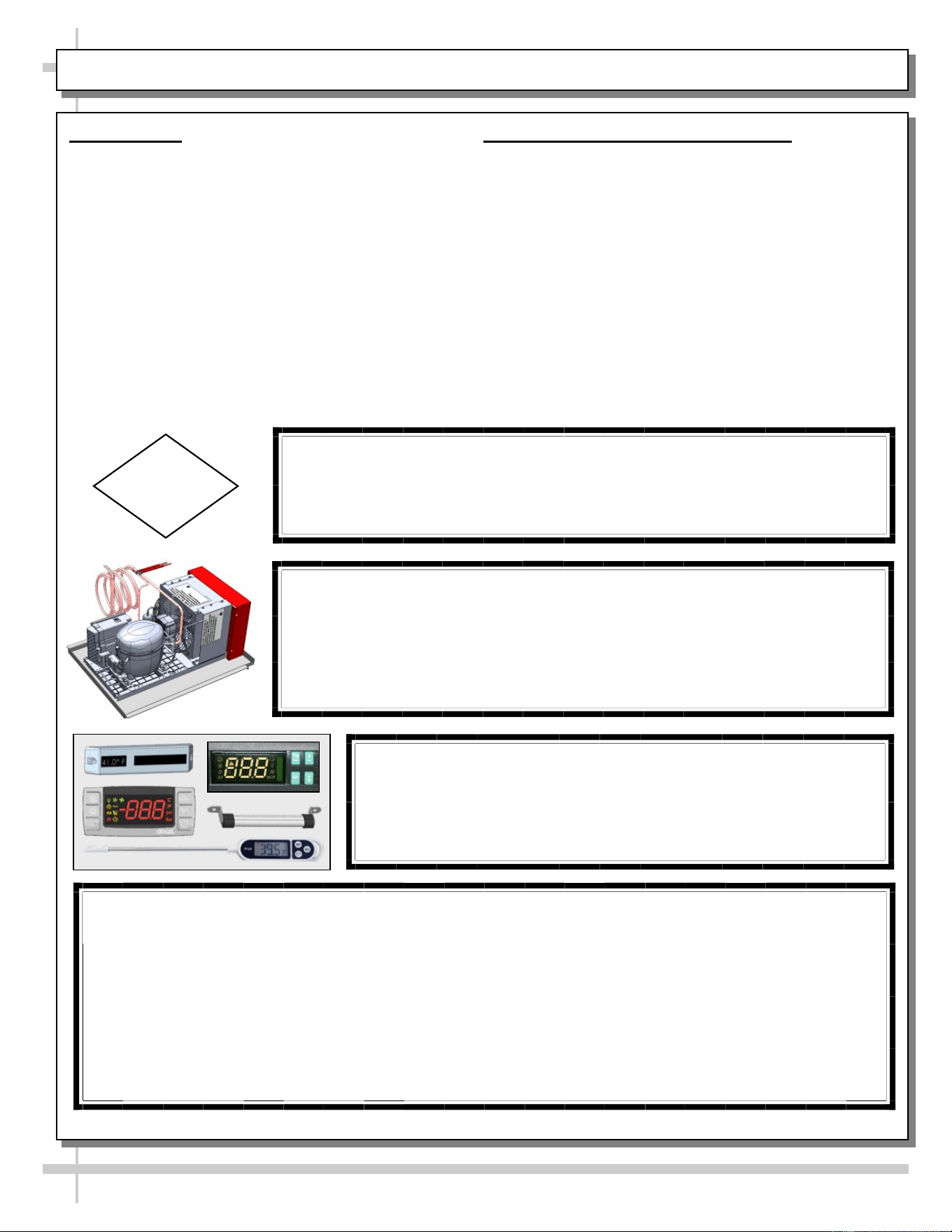
CAUTION! LAMP REPLACEMENT GUIDELINES
LED lamps reflect specific size, shape and design.
Any replacements must meet factory specifications, resist breakage
and reflect similar appearance as lamps from factory.
CAUTION
CAUTION! CHECK CONDENSATE PAN, POSITION & CONNECTIONS!
Water on flooring can cause extensive damage!
• Before powering up case, check that condensate pan is positioned directly
under case’s condensate drain.
• Also, check that there are NO LOOSE CONNECTIONS, including overflow
condensate pan and its power cord plug (if part of the condensate package).
CAUTION! DO NOT RELY ON THERMOMETERS OR
THERMOSTATS FOR PRODUCT (FOOD) TEMPERATURES.
• Thermometers & thermostats reflect air temperatures ONLY.
• For ACTUAL product (food) temperatures, use a calibrated food
probe thermometers ONLY.
• For accurate readings, DO NOT use infrared food thermometers.
WARNING
Do not use means to accelerate the defrosting process or to clean, other than those recommend-
ed by the manufacturer.
The appliance shall be stored in a room without continuously operating ignition sources (for ex-
ample: open flames, an operating gas appliance or an operating electric heater.)
Do not pierce or burn.
Be aware that refrigerants may not contain an odor.
6
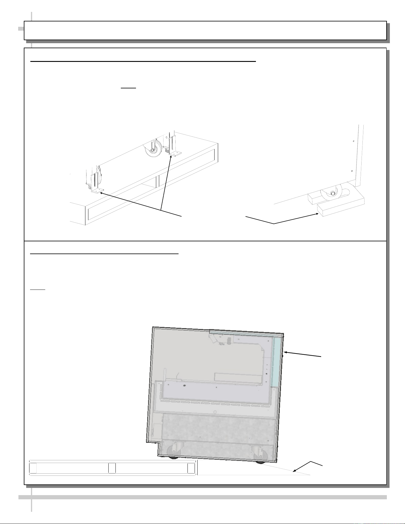
CASE REMOVAL FROM SKID (LOCKING/UNLOCKING CASTERS)
Various Types Of
Case Shipping
Brackets
1. Removing Case Shipping Brackets That Are Attached To Skid
• Remove screws holding shipping brackets to skid.
• Remove shipping brackets from skid.
• See illustrations below. Note: Shipping Brackets will vary in size, shape, material and location depending
upon case type and model.
2. Remove Case (With Casters) From Skid
A. Place ramp up against skid (to allow case to smoothly slide off from skid).
B. Maintain support of case at all times or center of gravity may cause case to fall.
C. Unlock Casters. Slide unit to rear of skid. Slide down ramp and off from skid.
Note: See next page for panel attachment instructions. CN33R shown for reference only, you model may
differ in appearance.
Support case
while sliding
down ramp.
Ramp
7
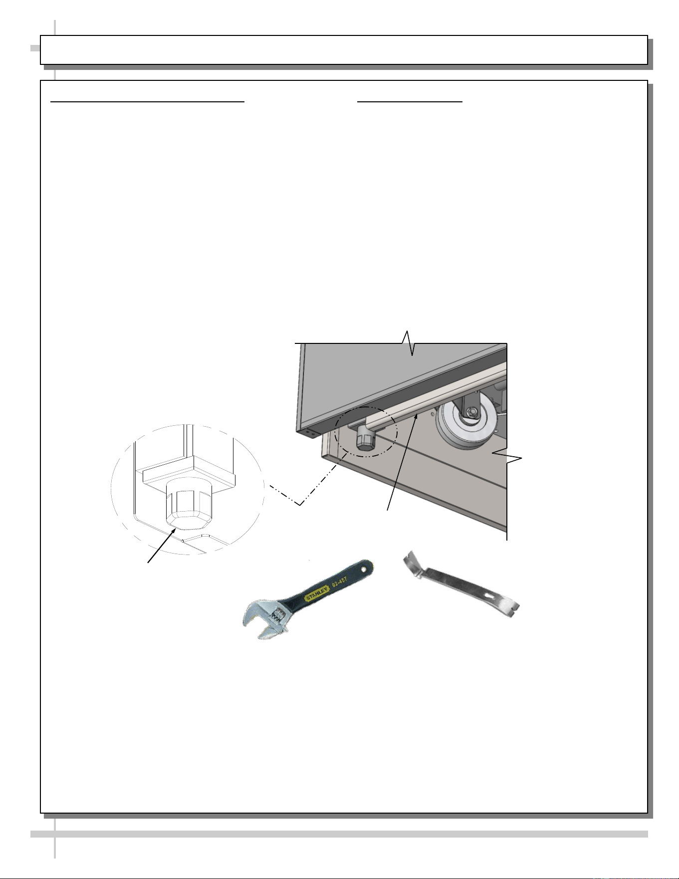
SHIMMING FRAME SUPPORT RAILS / ADJUSTING LEVELERS
1. Cases With Levelers: Adjust
• Important! For cases with casters, after case is in
proper position, levelers must then be
LOWERED to floor.
• Adjust case so it is level and plumb.
• You may need to remove front and/or rear
toe-kick to access levelers.
• Use adjustable wrench (and possibly a pry bar) to
adjust leveler.
• Do not use pry bar on toe-kick (it may buckle).
• Do not use pry bar on end panel (it may chip).
• Use pry bar ONLY on base frame to avoid
damaging case.
• Use a block to reach base frames with pry bar.
• See below illustrations.
2. Sealing Cases
• If the case is installed and intended to be sta-
tionary, a generous bead of food grade silicone
sealant along the bottom of the front toe-kick
and rear panel is needed.
• When properly applied, this food grade silicone
sealant will prevent water from seeping to the
floor as well as crumbs and other residue from
entering beneath the case.
Pry Bar
Base Frame
Leveler
Adjustable
Wrench
8
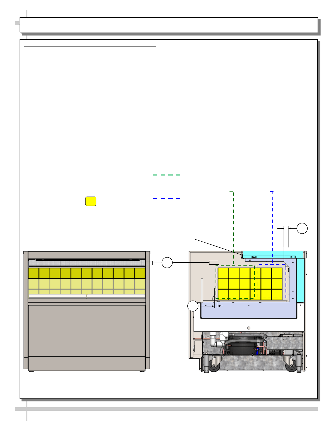
LOAD LEVEL GUIDE & TEMPERATURE GUIDE - MODELS C(T)(L)(H)R
LOAD LEVEL & TEMPERATURE GUIDE - MODELS C(T)(L)(H)R
>> FOLLOW THESE PRODUCT PLACEMENT GUIDELINES TO
MAINTAIN DESIRED PRODUCT TEMPERATURES.
>> FRONT TO REAR PRODUCT TEMPS ARE ESTIMATES ONLY.
>> NOTES CORRESPOND WITH ILLUSTRATIONS SHOWN.
1. ALLOW AT LEAST 1” SPACE BETWEEN PRODUCT AND
ITS SHELF ABOVE.
2. AT CASE REAR, ALLOW AT LEAST 1” SPACE BETWEEN
PRODUCT AND REAR PERFORATED PLENUM.
3. DO NOT BLOCK 1 1/4” AIR RETURN OPENING WITH PRODUCT.
>> IF YOU ARE UNABLE TO MAINTAIN DESIRED PRODUCT
TEMPERATURES, SEE TROUBLESHOOTING SECTION IN MANUAL.
37 °F TO 41 °F
PRODUCT AT
CASE FRONT
33 °F To 37 °F
PRODUCT AT
CASE REAR
MODEL C33R SHOWN ABOVE. CASE IS PARTIALLY DISASSEMBLED, CROSS SECTIONED
AND PACKAGED PRODUCT LADEN FOR ILLUSTRATIVE PURPOSES ONLY.
HEADER
PACKAGED
PRODUCT
ILLUSTRATION
PRODUCT
TEMPERATURE
RANGE SHOWN
AT RIGHT.
1
2
3
9
LOAD LEVEL GUIDE & TEMPERATURE GUIDE - MODELS C(L)(H)R
LOAD LEVEL & TEMPERATURE GUIDE - MODELS C(L)(H)R
>> FOLLOW THESE PRODUCT PLACEMENT GUIDELINES TO
MAINTAIN DESIRED PRODUCT TEMPERATURES.
>> FRONT TO REAR PRODUCT TEMPS ARE ESTIMATES ONLY.
>> NOTES CORRESPOND WITH ILLUSTRATIONS SHOWN.
1. ALLOW AT LEAST 1” SPACE BETWEEN PRODUCT AND
ITS SHELF ABOVE.
2. AT CASE REAR, ALLOW AT LEAST 1” SPACE BETWEEN
PRODUCT AND REAR PERFORATED PLENUM.
3. DO NOT BLOCK 1 1/4” AIR RETURN OPENING WITH PRODUCT.
>> IF YOU ARE UNABLE TO MAINTAIN DESIRED PRODUCT
TEMPERATURES, SEE TROUBLESHOOTING SECTION IN MANUAL.
37 °F TO 41 °F
PRODUCT AT
CASE FRONT
33 °F To 37 °F
PRODUCT AT
CASE REAR
MODEL C33R SHOWN ABOVE. CASE IS PARTIALLY DISASSEMBLED, CROSS SECTIONED
AND PACKAGED PRODUCT LADEN FOR ILLUSTRATIVE PURPOSES ONLY.
HEADER
PACKAGED
PRODUCT
ILLUSTRATION
PRODUCT
TEMPERATURE
RANGE SHOWN
AT RIGHT.
1
2
3
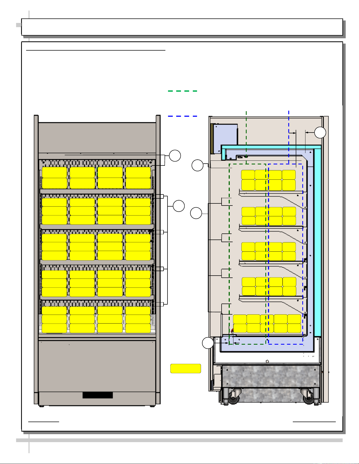
LOAD LEVEL GUIDE & TEMPERATURE GUIDE - MODEL B(T)(L)(H)R
LOAD LEVEL & TEMPERATURE GUIDE - MODEL B(T)(L)(H)R
>> FOLLOW THESE PRODUCT PLACEMENT GUIDELINES TO
MAINTAIN DESIRED PRODUCT TEMPERATURES.
>> FRONT TO REAR PRODUCT TEMPS ARE ESTIMATES ONLY.
>> NOTES CORRESPOND WITH ILLUSTRATIONS SHOWN.
1. AT TOP SHELF, KEEP PRODUCT BELOW THERMOMETER
(THAT IS ATTACHED TO REAR PERFORATED PLENUM).
2. ALLOW AT LEAST 1” SPACE BETWEEN PRODUCT AND ITS
SHELF ABOVE.
3. AT CASE REAR, ALLOW AT LEAST 1” SPACE BETWEEN
PRODUCT AND REAR PERFORATED PLENUM.
4. DO NOT BLOCK 1 1/4” AIR RETURN OPENING WITH PRODUCT.
>> IF YOU ARE UNABLE TO MAINTAIN DESIRED PRODUCT
TEMPERATURES, SEE TROUBLESHOOTING SECTION IN MANUAL.
37 °F TO 41 °F
PRODUCT AT
CASE FRONT
33 °F To 37 °F
PRODUCT AT
CASE REAR
PACKAGED
PRODUCT
ILLUSTRATION
PRODUCT
TEMPERATURE
RANGE SHOWN
AT RIGHT.
2
1
2
1
3
4
MODEL B37R SHOWN ABOVE. CASE IS PARTIALLY DISASSEMBLED, CROSS-SECTIONED
10
LOAD LEVEL GUIDE & TEMPERATURE GUIDE - MODELS C(L)(H)R
LOAD LEVEL & TEMPERATURE GUIDE - MODELS C(L)(H)R
>> FOLLOW THESE PRODUCT PLACEMENT GUIDELINES TO
MAINTAIN DESIRED PRODUCT TEMPERATURES.
>> FRONT TO REAR PRODUCT TEMPS ARE ESTIMATES ONLY.
>> NOTES CORRESPOND WITH ILLUSTRATIONS SHOWN.
1. ALLOW AT LEAST 1” SPACE BETWEEN PRODUCT AND
ITS SHELF ABOVE.
2. AT CASE REAR, ALLOW AT LEAST 1” SPACE BETWEEN
PRODUCT AND REAR PERFORATED PLENUM.
3. DO NOT BLOCK 1 1/4” AIR RETURN OPENING WITH PRODUCT.
>> IF YOU ARE UNABLE TO MAINTAIN DESIRED PRODUCT
TEMPERATURES, SEE TROUBLESHOOTING SECTION IN MANUAL.
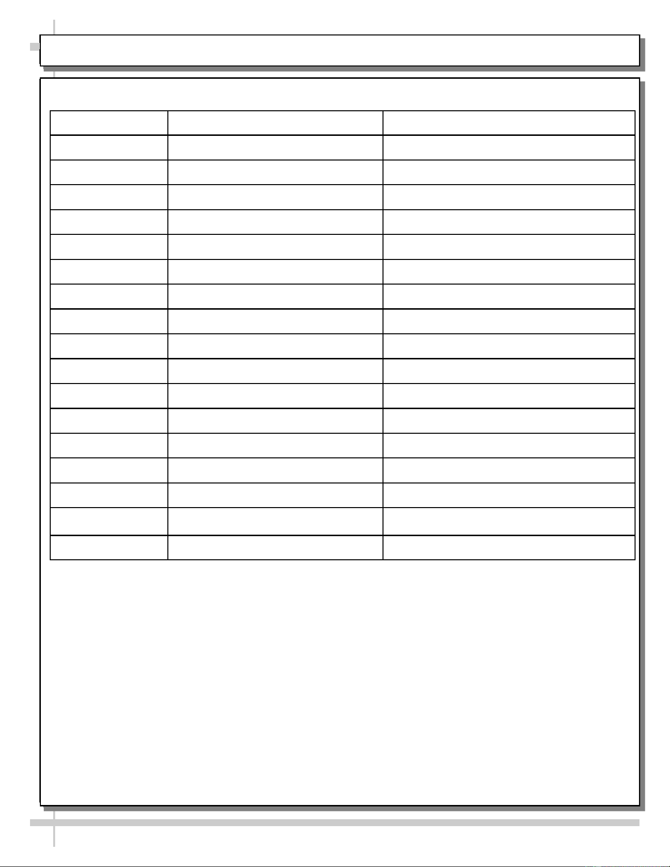
SHELF AND DECK LOAD LIMITS
The chart below are the load limits for the shelves and decks. All
weights below are for a uniform distributed load.
Model Max Shelf Load (lbs) Max Deck Pan Load (lbs)
B33R N/A 66
B43R N/A 92
B53R N/A 106
B63R N/A 132
B35R 110 66
B45R 154 92.4
B55R 198 105.6
B65R 231 132
BN37R 66 33
BN47R 92.4 46.2
BN57R 118.8 52.8
B37R 110 66
B47R 154 92.4
B57R 198 105.6
B67R 231 132
B37D 110 66
B47D 154 92.4
11
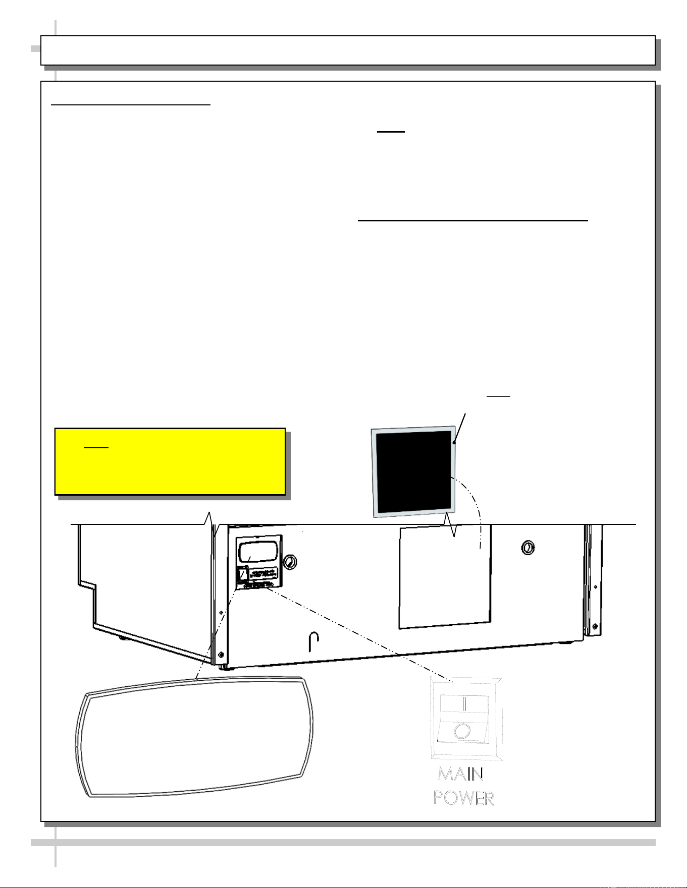
START-UP AND OPERATION: THERMOSTAT / MAIN POWER SWITCH / LIGHTS SWITCH / FILTER
1. Merchandiser Start-Up
• Do not use an extension cord with this appliance.
• Do not operate this equipment with a damaged
cord, plug or outlet.
• Ensure that the main power switch is off.
• Plug cord into a certified 110V electrical outlet with
ground.
• Turn main power switch on (see location at rear of
case in illustration below)
• Coil fans should turn on.
• From inside of the case, check for discharge
air from front baffle, to confirm that the fans
are functioning properly.
• When the case is in a start-up mode or has been
idle for a long period of time, unit may require 75
minutes running time to pull-down temperature.
• Turn lights on.
• Light switch is located on the ceiling of mer-
chandising area.
• The lights should come on at the same time.
• Always maintain front and rear airflow clearance
of twelve inches.
• Obstruction or restriction of air can void
warranty.
• Note: Case temperature setting is determined by
case size. Temperature is controlled by a
thermostat. If a temperature setting change is
required, refer to instructions in
PROGRAMMBLE CONTROLLER sections of
this manual.
2. Removable, Condenser Coil Filter
• A removable filter prevents impurities (dust, dirt
and debris) from entering condenser coil.
• Filter must be removed weekly and cleaned.
• See GENERAL CLEANING (TO BE
PERFORMED BY STORE PERSONNEL) -
EXTERIOR in this operating manual for
cleaning instructions.
Removable, Magnetic Condenser
Coil Filter (Optional). Note: Filter is
Placed over Condenser Coil Grille.
Note: Illustration Shown Reflects
REAR ACCESS Condenser Package.
Optional FRONT ACCESS Condenser
Package Has Similar Electrical Layout.
12
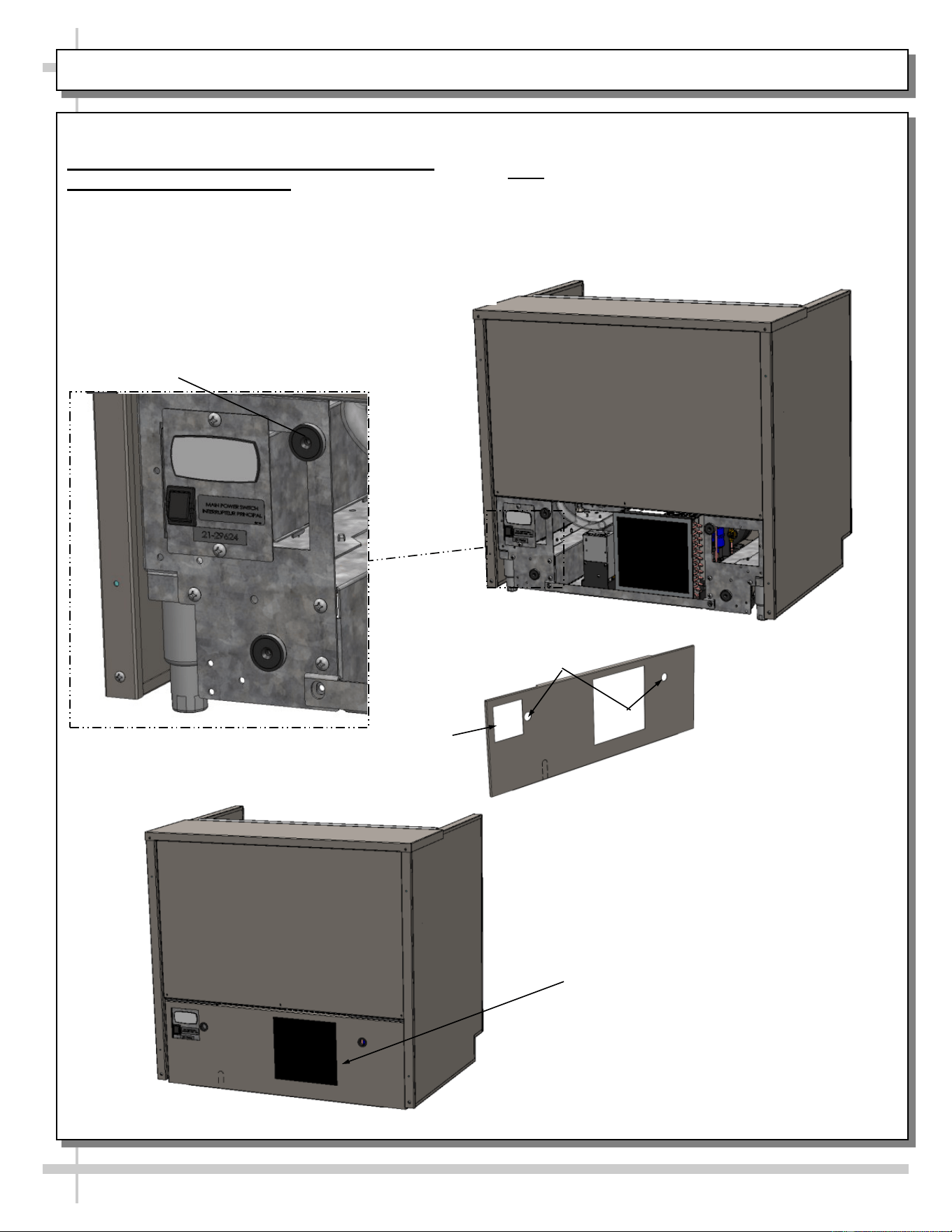
REFRIGERATION - REAR CONDENSATE PACKAGE ACCESS (NO SCREW REMOVAL REQUIRED)
Refrigeration Fundamentals, Continued
1. Rear Condensate Package Access - No
Screw Removal Required
• Assembly or disassembly and servicing of
condensate package is to be accomplished by
a licensed refrigeration contractor.
• Remove rear grille by grasping two (2) finger holes
and pulling outward.
• Rear grille will then be free from rear panel
magnets.
Note: CN33R shown for reference only, you model
may differ in appearance.
Model CN33R Fully Assembled
Model CN33R Disassembly
Rear Panel Magnet
Magnetic
Filter
Finger Holes
Controller Access
13
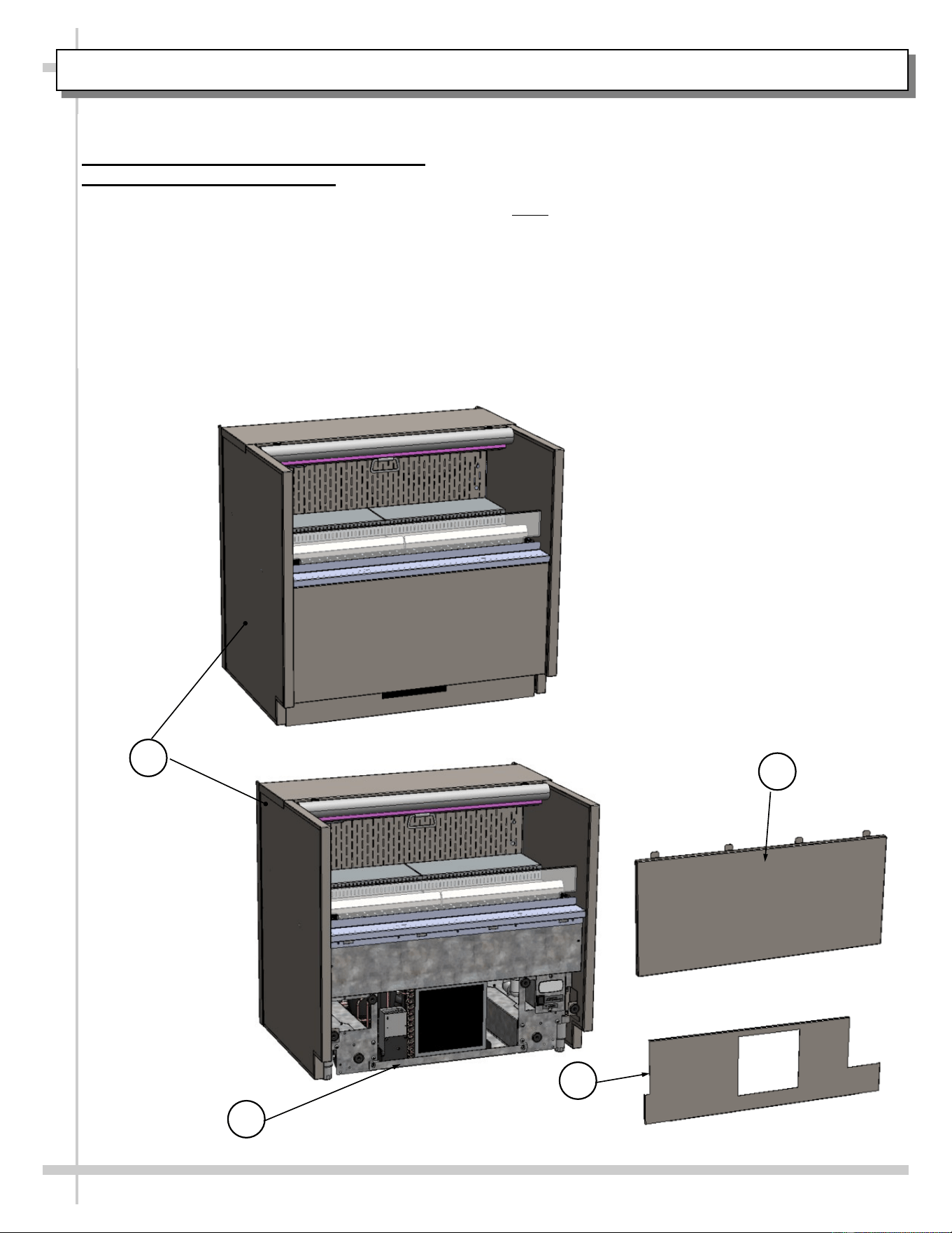
REFRIGERATION - FRONT CONDENSATE PACKAGE ACCESS (NO SCREW REMOVAL REQUIRED)
Refrigeration Fundamentals, Continued
2. Front Condensate Package Access -
No Screw Removal Required
• Assembly or disassembly and servicing of
condensate package is to be accomplished
by a licensed refrigeration contractor.
1. View of fully attached front panel and toe-kick.
2. Remove front panel by grabbing the bottom of
the panel and pull forward to release magnets.
Slide down to disengage the security tabs.
3. Remove the toe-kick from the magnets to access
the compressor package.
4. Carefully slide condenser package pan out
from under case to access various components.
>> Return all components to case in reverse or-
der they were removed.
Note: CN33R shown for reference only, you model
may differ in appearance.
1
2C
3B
2
4
3
4
14
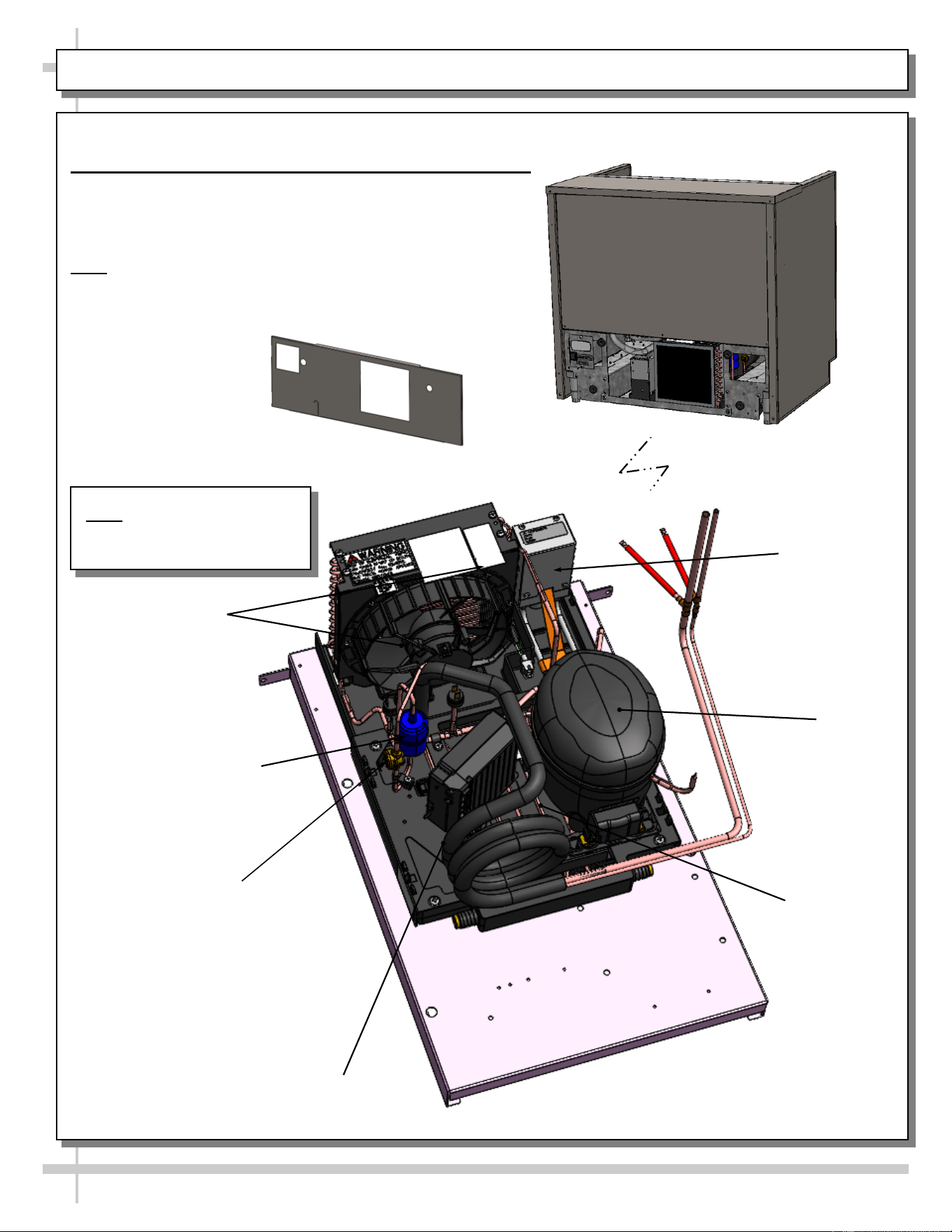
REFRIGERATION - CONDENSATE PACKAGE ILLUSTRATED PARTS BREAKDOWN
Refrigeration Fundamentals, Continued
3. Condensate Package Illustrated Parts Breakdown
• Assembly or disassembly and servicing to be
accomplished by licensed refrigeration contractor.
• After rear grille has been removed, slide condensate
package out slowly and carefully.
Note: CN33R shown for reference only, you model may differ
in appearance.
Note: Condensate Package
Is Shown Rotated For
Illustrative Purposes
Rear Grille
Sight Glass
Condensing Coil
(and Internal Fan)
Compressor
Filter Drier
Hot Gas Loop
Condensate
Pan
Compressor
Electrical
Box
Condensate
Overflow Pan
GENERAL CLEANING (TO BE PERFORMED BY STORE PERSONNEL)
15
FREQ. INSTRUCTIONS
Daily Sides/Top/Front Panel: Clean with mild all-purpose cleaner and soft cloth.
Daily Acrylic Air Deflector:
• Clean with mild all-purpose cleaner and soft cloth.
• Never use ammonia-based cleaners (nor household or commercial window cleaner) on
acrylic.
Daily Decks, Air Return Grilles, Product Display Risers & Shelving (If Any):
• Clean with mild all-purpose cleaner and soft cloth.
• For more thorough cleaning, remove from case rear (by lifting up and off). Submerse in
warm soapy water and use a nylon brush to remove hardened residue. Rinse thoroughly.
Dry with soft cloth. Return to case.
Weekly Magnetic Condenser Coil Filter (Self-Contained Units Only):
• Magnetic coil filter helps prevent dust particles from entering condenser coil.
• Access by removing front panel for front access cases or the rear panel for rear access
cases.
• Clean magnetic condenser coil filter by following these steps:
1. To clean by hand, (without using dishwasher), remove magnetic condenser coil filter
from case. Use a rag or soft-bristled brush to wipe off excess dust particles from filter.
Submerse in warm, soapy water. Use soft-bristled brush to remove dust, dirt, grease
and grime that may collect on filter. Rinse thoroughly. Skip to step #3.
2. As magnetic condenser coil filter is dishwasher safe, remove from case (no screw
removal required) and use a rag or soft-bristled brush to wipe off excess dust particles
from filter. Run in normal dishwasher cycle. Remove from dishwasher. Go to next step.
3. Dry with soft cloth or paper towel or allow to air dry. Replace.
Weekly Rear Perforated Plenum:
• Clean with mild all-purpose cleaner and soft cloth.
Monthly Security Cover (Optional):
• Wipe down with mild all-purpose cleaner and soft cloth.
• Dry with soft cloth.
Quarterly Under Case Cleaning: Quarterly (or whenever condenser package is removed from under
case, vacuum (or broom) under case to remove dust, debris and dirt that may collect.
Quarterly Evaporator Coil and Tub:
• Turn off the main power and unplug the case.
• Remove evaporator fan panel and clean tub, coil, and drain with warm water and mild
soap solution. Remove any debris that may clog drain.
• Plug the case back in and turn on the main power.
16
WARNING! TURN OFF CASE BEFORE PERFORMING PREVENTIVE MAINTENANCE!
Maintenance and Service Notes
• All maintenance staff and others working in the local area shall be instructed on the nature of work
being carried out. Work in confined spaces shall be avoided.
• The area shall be checked with an appropriate refrigerant detector prior to and during work, to ensure
the technician is aware of potentially toxic or flammable atmospheres. Ensure that the leak detection
equipment being used is suitable for use with all applicable refrigerants, i.e., nonsparking, adequately
sealed, or intrinsically safe.
• If any hot work is to be conducted on the refrigerating equipment or any associated parts, appropriate
fire extinguishing equipment shall be available on hand. A dry chemical or CO
2
fire extinguisher
should be adjacent to the charging area.
• No person carrying out work in relation to a refrigerating system which involves exposing any pipe
work shall use any sources of ignition in such a manner that it may lead to the risk of fire or explosion.
All possible ignition sources, including cigarette smoking should be keep sufficiently far away from the
site of installation, repairing, removing and disposal, during which refrigerant can possible be released
to the surround space. Prior to work taking place, the area around the equipment shall be surveyed to
make sure that there are no flammable hazards or ignition risks. “No Smoking” signs shall be dis-
played.
• Ensure that the area is in the open or that it is adequately ventilated before breaking into the system
or conducting any hot work. A degree of ventilation shall continue during the period that the work is
carried out. The ventilation should safely disperse any released refrigerant and preferably expel it ex-
ternally into the atmosphere.
Checks to the refrigerating equipment
• Where electrical components are being changed, they shall be fit for the purpose and to the correct
specification. At all times, the manufacturer’s maintenance and service guidelines shall be followed. If
in doubt, consult the manufacturer’s technical department for assistance.
• The following check shall be applied to installation using FLAMMABLE REFRIGERANTS:
a) the actual REFRIGERANT CHARGE is in accordance with the room size within which the re-
frigerant containing parts are installed;
b) the ventilation machinery and outlets are operating adequately and are not obstructed;
c) if an indirect refrigeration circuit is being used, the secondary circuit shall be checked for the
presence of refrigerant;
d) marking to the equipment continues to be visible and legible. Markings and signs that are illegi-
ble shall be corrected;
e) refrigerating pipe or components are installed in a position where they are unlikely to be ex-
posed to any substance which may corrode refrigerant containing components, unless the
components are constructed of materials which are inherently resistant to being corroded or
are suitably protected against being so corroded.
Checks to electrical devices
• Repair and maintenance to electrical components shall include initial safety checks and component
inspection procedures. If a fault exists that could compromise safety, then no electrical supply shall be
connected to the circuit until it is satisfactorily dealt with. If the fault cannot be corrected immediately
but it is necessary to continue operation, an adequate temporary solution shall be used. This shall be
reported to the owner of the equipment, so all parties are advised.
• Initial safety checks shall include:
a) that capacitors are discharged: this shall be done in a safe manner to avoid possibility of
sparking;
b) that no live electrical components and wiring are exposed while charging, recovering or purg-
ing the system;
c) that there is continuity of earth bonding.
PREVENTIVE MAINTENANCE - TO BE PERFORMED BY TRAINED SERVICE PROVIDERS ONLY - 1 of 7
17
WARNING! TURN OFF CASE BEFORE PERFORMING PREVENTIVE MAINTENANCE!
Maintenance and Service Notes
Repairs to sealed components
• During repairs to sealed components, all electrical supplies shall be disconnected from the equipment
being worked upon prior to any removal of sealed covers, etc. If it is absolutely necessary to have an
electrical supply to equipment during servicing, then a permanent opening form of leak detection shall
be located at the most critical point to warn of a potentially hazardous situation.
• Particular attention shall be paid to the following to ensure that by working on electrical components,
the casing is not altered in such a way that the level of protection is affected. This shall include dam-
age to cables, excessive number and connections, terminals not made to original specification, dam-
age to seals, incorrect fitting of glands, etc.
• Ensure that the apparatus is mounted securely.
• Ensure that seals or sealing materials have not degraded to the point that they no longer serve the
purpose of preventing the ingress of flammable atmospheres. Replacement parts shall be in accord-
ance with the manufacturer’s specifications.
Repair to intrinsically safe components
• Do not apply any permanent inductive or capacitance loads to the circuit without ensuring that this will
not exceed the permissible voltage and current permitted for the equipment in use.
• Intrinsically safe components are the only types that can be worked on while live in the presence of a
flammable atmosphere. The test apparatus shall be at the correct rating.
• Replace components only with parts specified by the manufacturer. Other parts can result in the igni-
tion of refrigerant in the atmosphere from a leak.
• NOTE The use of silicon sealant can inhibit the effectiveness of some types of leak detection equip-
ment. Intrinsically safe components do not have to be isolated prior to working on them.
Cabling
• Check that cabling will not be subject to wear, corrosion, excessive pressure, vibration, sharp edges,
or any other adverse environmental effects. The check shall also take into account the effects of aging
or continual vibration from sources such as compressors or fans.
Detection of flammable refrigerants
• Under no circumstances shall potential sources of ignition be used in the searching for or detection of
refrigerant leaks. A halide torch (or any other detector using a naked flame) shall not be used.
• The following lead detection methods are deemed acceptable for all refrigerant systems.
• Electronic leak detectors may be used to detect refrigerant leaks but, in the case of FLAMMABLE RE-
FRIGERANTS the sensitivity might not be adequate, or might need recalibration. (Detection equip-
ment shall be calibrated in a refrigerant-free area.) Ensure that the detector is not a potential source of
ignition and is suitable for the refrigerant used. Leak detection equipment shall be set at a percentage
of the LFL of the refrigerant and shall be calibrated to the refrigerant employed, and the appropriate
percentage of gas (25% maximum) is confirmed.
• Leak detection fluids are also suitable for use with most refrigerants but the use of detergents contain-
ing chlorine shall be avoided as the chlorine can react with the refrigerant and corrode the copper pipe
-work.
• NOTE examples of leak detection fluids are
-bubble method.
-fluorescent method agents.
• If a leak is suspected, all naked flames shall be removed/extinguished.
• If a leakage of refrigerant is found which requires brazing, all of the refrigerant shall be recovered from
the system, or isolated (by means of shut off valves) in a part of the system remote from the leak. Re-
moval of refrigerant shall be according to the removal and evacuation procedures below.
PREVENTIVE MAINTENANCE - TO BE PERFORMED BY TRAINED SERVICE PROVIDERS ONLY - 2 of 7
18
WARNING! TURN OFF CASE BEFORE PERFORMING PREVENTIVE MAINTENANCE!
Maintenance and Service Notes
Removal and evacuation
• When breaking into the refrigerant circuit to make repairs-or for any other purpose-conventional proce-
dures shall be used. However, for flammable refrigerants it is important that the best practice be fol-
lowed, since flammability is a consideration. The following procedure shall be adhered to:
a) safely remove refrigerant following local and national regulations;
b) purge the circuit with inert gas;
c) evacuate (optional for A2L);
d) purge with inert gas (optional for A2L);
e) open the circuit by cutting or brazing.
• The refrigerant change shall be recovered into the correct recovery cylinders if venting is not allowed
by local and national codes. For appliances containing flammable refrigerants, the system shall be
purged with oxygen-free nitrogen to render the appliance safe for flammable refrigerants. This process
might need to be repeated several times. Compressed air or oxygen shall not be used for purging re-
frigerant systems.
• For appliances containing flammable refrigerants, refrigerant purging shall be achieved by breaking
the vacuum in the system with oxygen-free nitrogen and continuing to fill until the working pressure is
achieved, then venting to atmosphere, and finally pulling down to a vacuum (optional for A2L). This
process shall be repeated until no refrigerant is within the system (optional for A2L). When the final
oxygen-free nitrogen change is used, the system shall be vented down to atmospheric pressure to
enable work to take place.
• Ensure that the outlet for the vacuum pump is not close to any potential ignition sources and that ven-
tilation is available.
Charging procedures
• In addition to conventional charging procedures, the following requirements shall be followed.
a) Ensure that contamination of different refrigerants does not occur when using charging equip-
ment. Hoses or lines shall be as short as possible to minimize the amount of refrigerant con-
tained in them.
b) Cylinders shall be kept in an appropriate position according to the instructions.
c) Ensure that the REFRIGERATING SYSTEM is earthed prior to charging the system with refrig-
erant.
d) Label the system when charging is complete (if not already).
e) Extreme care shall be taken not to overfill the REFRIGERATING SYSTEM.
• Prior to recharging the system. It shall be pressure-tested with the appropriate purging gas. The sys-
tem shall be lead-tested on completion of charging but prior to commissioning. A follow up leak test
shall be carried out prior to leaving the site.
PREVENTIVE MAINTENANCE - TO BE PERFORMED BY TRAINED SERVICE PROVIDERS ONLY - 3 of 7
19
WARNING! TURN OFF CASE BEFORE PERFORMING PREVENTIVE MAINTENANCE!
Maintenance and Service Notes
Decommissioning
• Before carrying out this procedure, it is essential that the technician is completely familiar with the
equipment and all its detail. I tis recommended good practice that all refrigerants are recovered safe-
ly. Prior to the task being carried out, an oil and refrigerant sample shall be taken in case analysis is
required prior to re-use of recovered refrigerant. It is essential that electrical power is available before
the task is commenced.
a) Become familiar with the equipment and its operation.
b) Isolate the system electrically.
c) Before attempting the procedure, ensure that:
i) mechanical handling equipment is available, if required, for handling refrigerant cylin-
ders;
ii) all personal protective equipment is available and being used correctly;
iii) the recovery process is supervised at all times by a competent person;
iv) recovery equipment and cylinders conform to the appropriate standards.
d) Pump down refrigerant system, if possible.
e) If a vacuum is not possible, make a manifold so that refrigerant can be removed from various
parts of the system.
f) Make sure that cylinder is situated on the scales before recovery takes place.
g) Start the recovery machine and operate in accordance with instructions.
h) Do not overfill cylinders (no more than 80% volume liquid charge).
i) Do not exceed the maximum working pressure of the cylinder, even temporarily
j) When the cylinders have been filled correctly and the process completed, make sure that the
cylinders and the equipment are removed from the site properly and all isolation valves on the
equipment are closed off.
k) Recovered refrigerant shall not be charged into another refrigerating system unless it has been
cleaned and checked.
• Equipment shall be labelled stating that it has been de-commissioned and emptied of refrigerant. The
label shall be dated and signed. For appliances containing flammable refrigerants, ensure that there
are labels on the equipment stating the equipment contains flammable refrigerant.
PREVENTIVE MAINTENANCE - TO BE PERFORMED BY TRAINED SERVICE PROVIDERS ONLY - 4 of 7
20
WARNING! TURN OFF CASE BEFORE PERFORMING PREVENTIVE MAINTENANCE!
Maintenance and Service Notes
Recovery
• When removing refrigerant from a system, either for servicing or decommissioning, it is recommended
good practice that all refrigerants are removed safely.
• When transferring refrigerant into cylinders, ensure that only appropriate refrigerant recovery cylinders
are employed. Ensure that the correct number of cylinders for holding the total system charge is avail-
able. All cylinders to be used are designated for the recovered refrigerant and labeled for that refriger-
ant (i.e., special cylinders for the recovery of refrigerant). Cylinders shall be complete with pressure-
relief valve and associated shut-off valve in good working order. Empty recovery cylinders are evacu-
ated and, if possible, cooled before recovery occurs.
• The recovery equipment shall be in good working order with a set of instructions concerning the equip-
ment that is at hand and shall be suitable for the recovery of all appropriate refrigerants including,
when applicable, FLAMMABLE REFRIGERANTS. In addition, a set of calibrated weighing scales shall
be available and in good working order. Hoses shall be complete with leak-free disconnect coupling
and in good condition. Before using the recovery machine, check that it is in satisfactory working or-
der, has been properly maintained and that any associated electrical components are sealed to pre-
vent ignition in the event of refrigerant release. Consult manufacturer if in doubt.
• The recovered refrigerant shall be returned to the refrigerant supplier in the correct recovery cylinder,
and the relevant waste transfer note arranged. Do not mix refrigerants in recovery units and especially
not in cylinders.
• If compressors or compressor oils are to be removed, ensure that they have been evacuated to an
acceptable level to make certain that FLAMMABLE REFRIGERANT does not remain within the lubri-
cant. The evacuation process shall be carried out prior to returning the compressor to the suppliers.
Only electric heating to the compressor body shall be employed to accelerate this process. When oil is
drained from a system, it shall be carried out safely.
PREVENTIVE MAINTENANCE - TO BE PERFORMED BY TRAINED SERVICE PROVIDERS ONLY - 5 of 7
21
WARNING! TURN OFF CASE BEFORE PERFORMING PREVENTIVE MAINTENANCE!
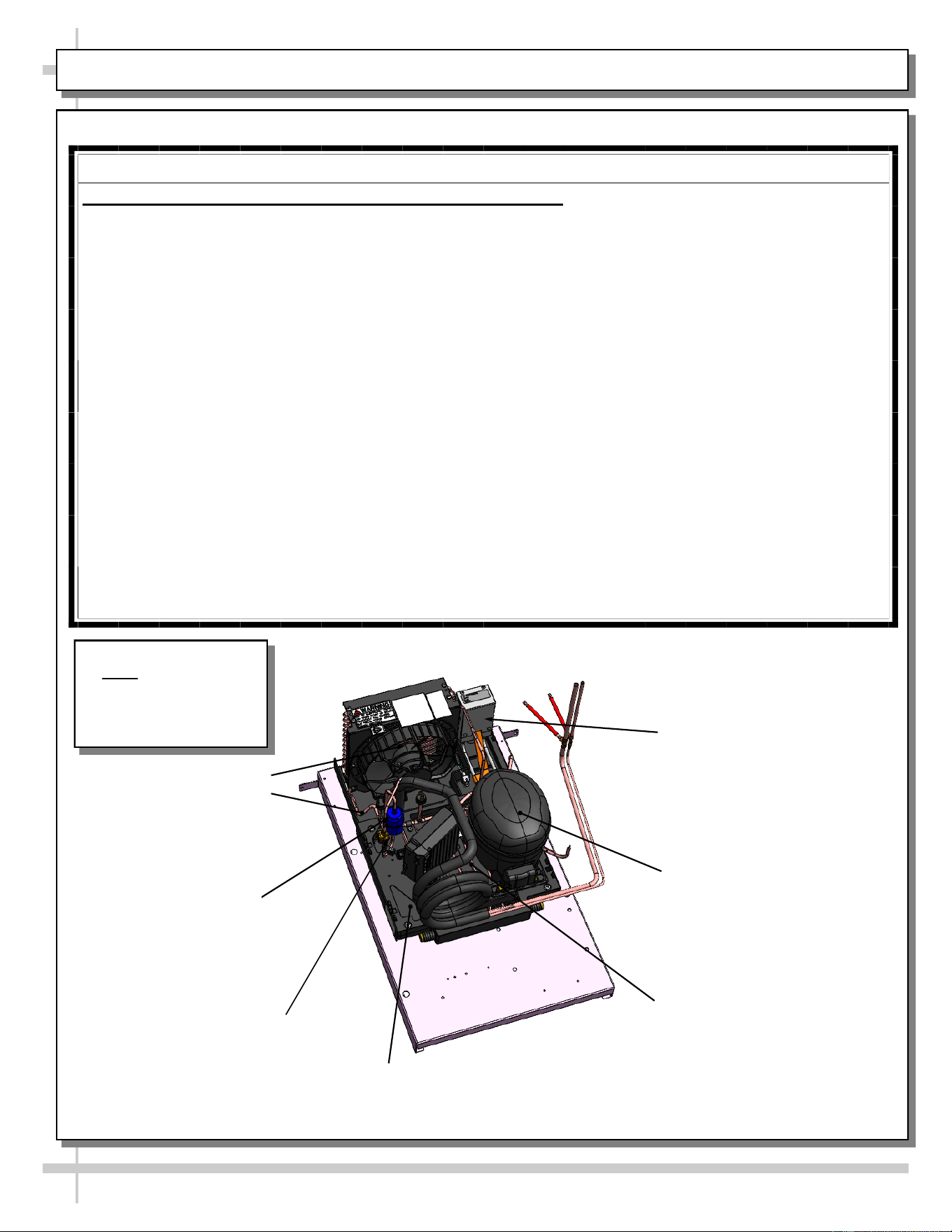
QUARTERLY PREVENTIVE MAINTENANCE INSTRUCTIONS
Condensate Package (Including Overflow Condensate Pan):
Caution! You must turn main power switch off before cleaning!
• Remove front (or rear) grille (by removing thumbscrews or disconnecting from magnets).
• Carefully slide out refrigeration assembly (taking care to not damage coil)!
• Remove wicking material (if any).
• Use vacuum (in suction mode) and brush to dislodge and remove dust both in and on coil fins.
• To remove dust/debris from inner fins, place damp rags around condensing fan motor brackets (to
collect airborne dust). Then, switch vacuum to blow mode to blow air through condenser coils and into
damp rags on fans. Blow entire surface of condensing coil to assure that all entrenched dust is
removed. Caution! Coil fins are sharp!
• Use a scrub-brush and a non-corrosive de-scaling solution (to remove calcium, lime and rust) from
condensate pan. Clean hot gas loop (for EnergyWise units) or electric coil (for standard units). Follow
instructions as to proper dilution, safety precautions and scrubbing method.
• After thoroughly cleaning pan with scrub-brush and solution, rinse component with clean water and
wipe dry with sponge or paper towel.
• Use mild all-purpose cleaner and soft cloth to clean fans, sight glass, overflow pan, etc.
• Return wicking material to mounting brackets. If wicking material is tattered, torn or disintegrating,
replace with new. If wicking material is not available, contact Structural Concepts. See toll-free
number at last page of operating manual.
• Slide condenser package back under case.
• Return front (or rear) grille to case.
• Turn power back on to case.
PREVENTIVE MAINTENANCE - TO BE PERFORMED BY TRAINED SERVICE PROVIDERS ONLY - 6 of 7
Note: Condensate
Package Is Shown
Rotated For
Illustrative Purposes
Sight Glass
Condensing Coil
(and Internal Fan)
Compressor
Compressor
Electrical Box
Filter
Hot Gas Loop
Condensate Pan
Condensate Overflow
Pan
22
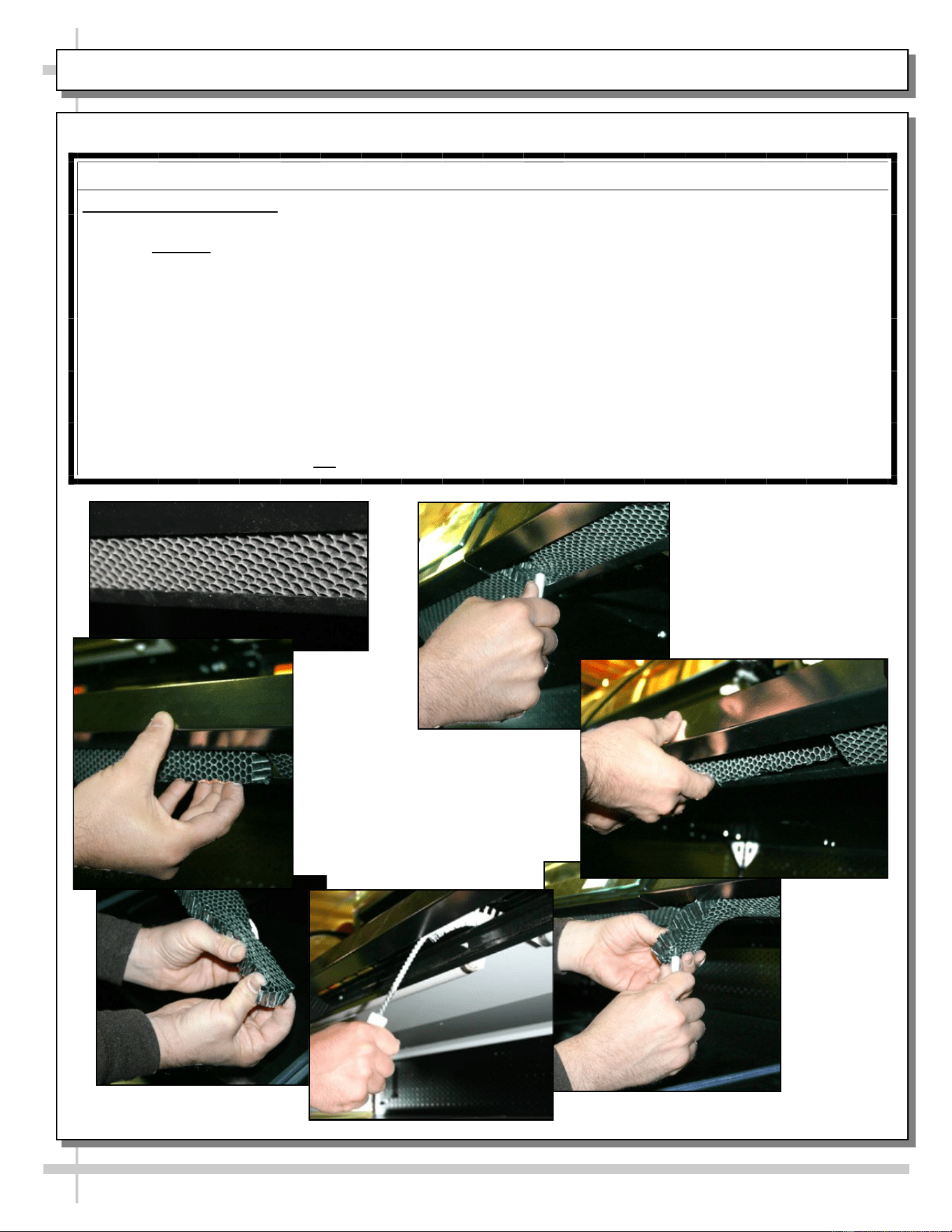
PREVENTIVE MAINTENANCE - TO BE PERFORMED BY TRAINED SERVICE PROVIDERS ONLY - 7 of 7
A
B
C
E
F
G
D
ANNUAL (OR AS NEEDED) PREVENTIVE MAINTENANCE INSTRUCTIONS
Honeycomb Air Diffuser:
A. Wedge a non-metallic device of suitable strength (such as a ballpoint pen) between honeycomb and its
housing. Caution! Use care not to dislodge the heating wire (that prevents condensation on the
honeycomb retainer).
B. Apply pressure to collapse honeycomb to pull it out of honeycomb retainer.
C. Carefully pry downward and away from the honeycomb retainer.
D. Use brush to reach in and, with outward sweeping motion, pull any crumbs or residue out of
honeycomb area.
> Clean honeycomb with warm water and soap solution. Submerse if necessary. Use brush to dislodge
stubborn or sticky residue. Dry by using vacuum’s blow mode.
E. After honeycomb has been thoroughly cleaned and dried, squeeze honeycomb to allow it to fit into the
honeycomb retainer.
F. Carefully slide honeycomb into place.
G. Adjust honeycomb so it fits flat against retainer (not be wavy or out of position).
WARNING! TURN OFF CASE BEFORE PERFORMING PREVENTIVE MAINTENANCE!
TROUBLESHOOTING (TO BE PERFORMED BY STORE PERSONNEL) - PAGE 1 OF 2
23
CONDITION TROUBLESHOOTING
Water Is On The Floor Call service provider.
Fan Emits Excessive Noise Call service provider.
No Case Lights Are Working Check that light switch is in the on position.
Check that ALL of the light cords and plugs are properly connected.
See LED LIGHT FIXTURES: REPAIR / REMOVAL / REPLACEMENT
section in this manual for specifics.
Check circuit breaker box for tripped circuit.
If case lights still do not come on, call service provider.
Case Light Is Not Working Check that ALL of the light cords and plugs are properly connected.
This includes the following items:
• Oval form of plug must connect to oval form of LED light.
• See MAINTENANCE FUNDAMENTALS - LED LIGHT FIXTURE /
LOCATION / REPAIR / REPLACEMENT section in this manual for
more specifics including illustrations.
If case light still does not come on, call service provider.
Case is Not Holding Proper
Temperature
If a large amount of warm product was added to the case, it will take time
for the temperature to adjust. Product must be pre-chilled before placing
in case.
Check that the case is not in the sun or near a heat or air-conditioning
vent. See OVERVIEW / TYPE / COMPLIANCE / WARNINGS /
PRECAUTIONS / WIRING / PLUGS section in manual for specifics.
If case is located near front doors, temperature fluctuation can hinder
unit’s ability to maintain temperature. See OVERVIEW / TYPE /
COMPLIANCE / WARNINGS / PRECAUTIONS / WIRING / PLUGS
section in this manual for specifics.
Check that filter and condenser coil has been cleaned. See GENERAL
CLEANING (TO BE PERFORMED BY STORE PERSONNEL) section in
this manual for specifics.
Check air return grilles (area at front of decking) for obstructions.
DO NOT set product on air grilles as this will prevent proper airflow!
If case still is not holding proper temperature, call service provider.
TROUBLESHOOTING (TO BE PERFORMED BY STORE PERSONNEL), CONT’D - PAGE 2 OF 2
24
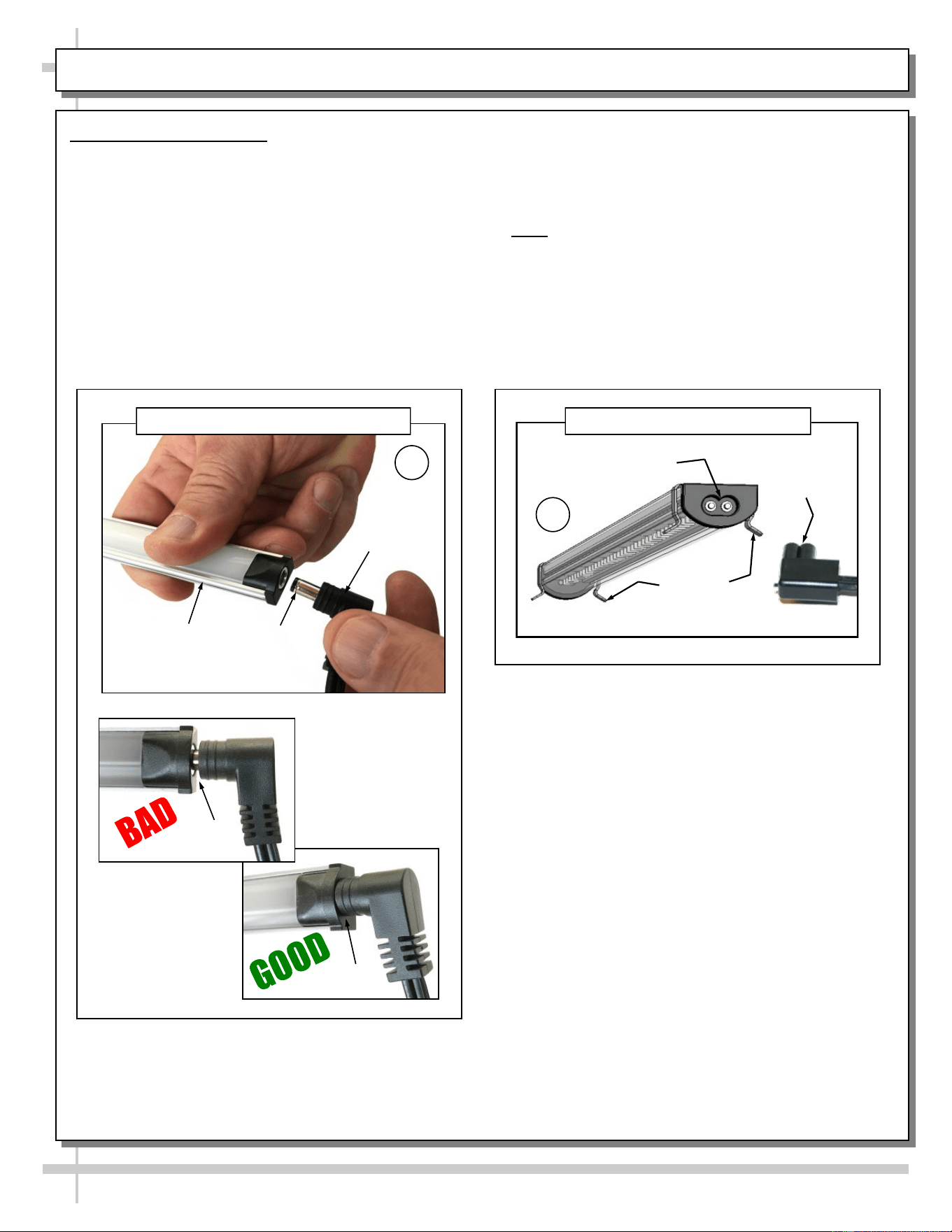
LED Style Light Fixtures
Removal of faulty LED light:
• LED lights rarely require change-out.
• To remove faulty LED light, simply grasp light
near retaining spring and carefully pull away
from its spring. Disconnect plug from LED’s
socket.
• Contact Structural Concepts’ Technical Service
Department for replacement parts (see
Technical Service section of this manual for
information).
LED’s Oval Form
Plug’s
Oval Form
--- LED Plug & Light Fixture ---
Retaining
Springs
Plug
A
B
LED’s Barrel
Shaped
Insert
LED
Light
“B-Shaped” LED Plug & Light Fixture
“Barrel-Shaped” LED Plug & Light Fixture
Replacement of LED light:
• To replace LED light fixture, simply insert new
LED light at proper position (socket must be near
plug). Carefully snap into metal springs so LEDs
are held firmly in place.
• Note: LED light and plug must be connected in a
specific manner or they will not work.
A. Certain plug designs (“barrel type”) merely require
that plug be pushed all the way in.
B. Other plugs require “oval edge” of plug to
connect to oval edge of LED light.
• See illustrations below.
No Gap
Gap
25
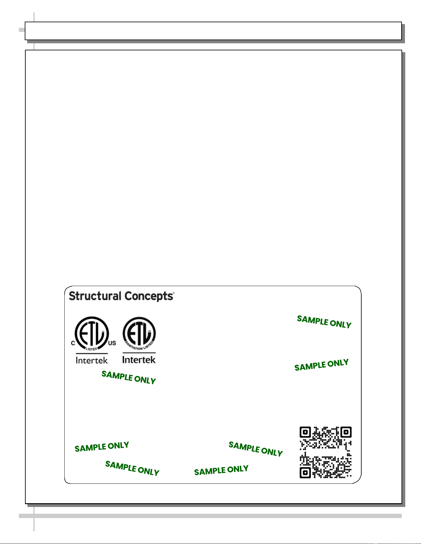
SERIAL LABEL LOCATION & INFO LISTED / TECH INFO & SERVICE / REFRIGERATED CASES ONLY
--- Sample Serial Label For Refrigerated Cases ---
MODEL NRS3648RXV-SAMPLE
SERIAL NO. 12345X30DZ098765
888 E. Porter Rd - Muskegon, MI 49441
3048256
Conforms to UL Std. 471
Conforms to NSF/ANSI Stds. 2 & 7
CERTIFIED TO CAN/CSA
STD C22.2 NO 120
ELECTRICAL RATING
REFRIGERANT
DESIGN PRESSURE
MINIMUM CIRCUIT AMPACITY
MAXIMUM OVERCURRENT
120/1/60 16 A
R513A AMOUNT 50 OZ
HIGH 186 LOW 88
20A
20A
Super Heat Temp 6-8 °F FOR PARTS AND SERVICE
Defrost 6 defrosts per day, 45 °F CALL 1-800-433-9490
Serial Label Location & Information Listed /
Technical Information & Service
• Serial labels are affixed at a wide range of places
(on the header, near thermostat, at case rear,
behind panels/toe-kicks, on electrical boxes, etc.).
• Serial labels contain electrical, temperature and
refrigeration information, as well as regulatory
standards to which the case conforms.
• Sample serial label is shown. A variety of models is
displayed on serial label for illustration purposes only.
Your case’s serial label will reflect only one model.
• For additional technical information and service, see
the TECHNICAL SERVICE page in this manual for
instructions on contacting Structural Concepts’
Technical Service Department.
Reveal
Harmony
Fusion
Impulse
Addenda
Blend
Grocerant
Oasis
Sample QR Code
SCAN FOR PRODUCT LITERATURE
SAMPLE ONLY
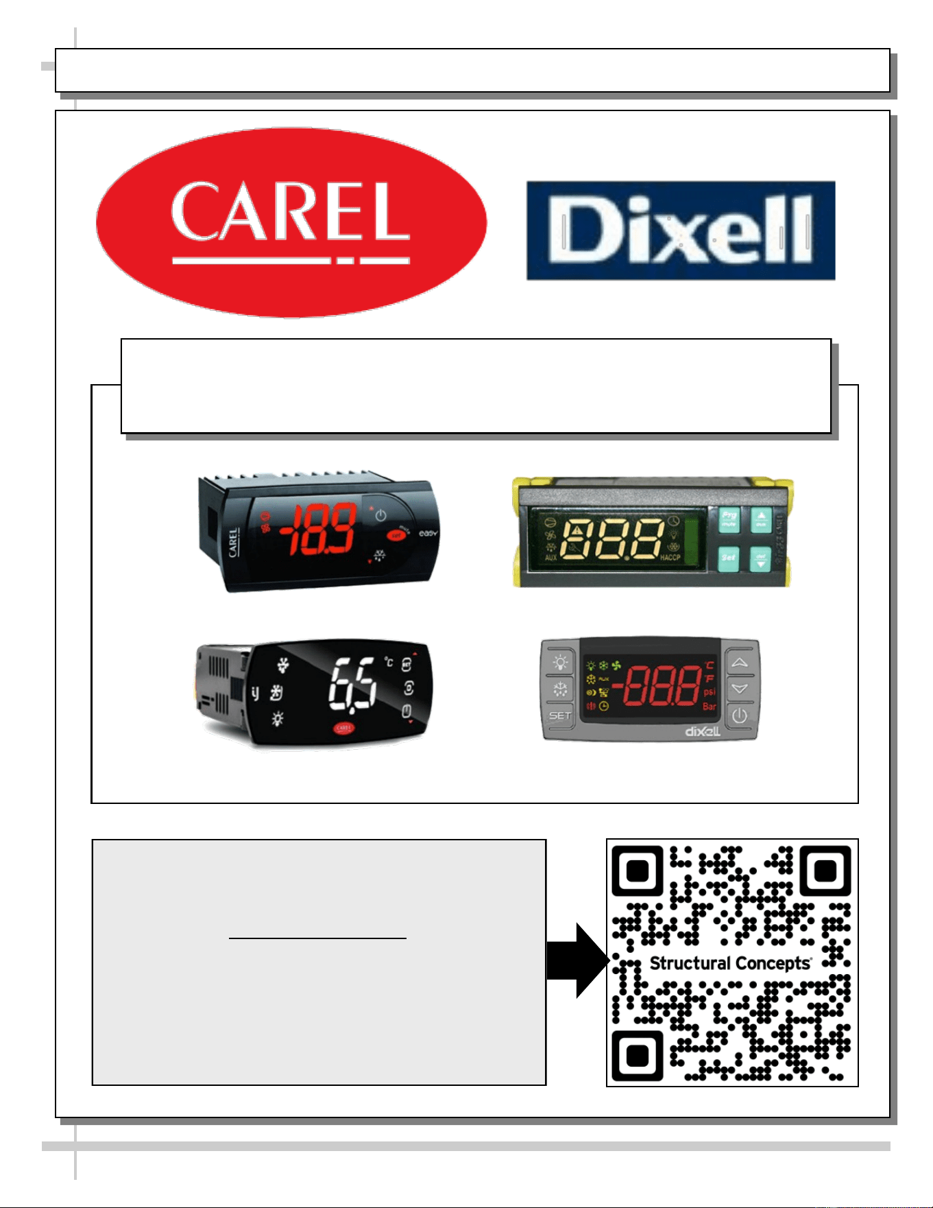
PROGRAMMABLE CONTROLLER (SELECT, CLICK ON OR SCAN QR CODE FOR INFORMATION)
26
Carel® iJF Platform
Carel® PJEZ Platform
Carel® ir33 Platform
Dixell® XM670K-XM679K Platform
To Access Information About The Programmable
Controller That Is Used On Your Case,
Follow These Instructions:
> If Viewing This Document on Smart Phone, Tablet
or Computer, Select/Click On The QR Code at Right.
> If Viewing This Document In Print (Hard Copy),
Scan The QR Code at Right With Your Smart Phone
or Tablet.
Determine Which Programmable Controller Is On Your Case (Controllers
That Are Commonly Used By Structural Concepts Are Shown Below).
Your Particular Programmable Controller May Differ.
STRUCTURAL CONCEPTS TECHNICAL SERVICE CONTACT INFORMATION & LIMITED WARRANTY
27
TECH SERVICE/WARRANTY CONTACT INFO:
1 (800) 433-9490 / EXTENSION 1
DAYS/HOURS AVAILABLE:
MONDAY - FRIDAY (CLOSED HOLIDAYS)
8:00 AM to 8:00 PM EST
YOU MUST HAVE THE FOLLOWING INFO AVAILABLE
BEFORE CONTACTING STRUCTURAL CONCEPTS:
SERIAL NO. / MODEL NO. / STORE NO. / STORE
ADDRESS / DETAILS (PHOTOS, LEAK LOCATIONS,
DAMAGE, STORE’S AMBIENT CONDITIONS, ETC.)
To Access The Limited Warranty To Your
Case, Follow These Instructions:
> If Viewing This Document on Smart Phone,
Tablet or Computer, Select/Click On The QR
Code at Right.
> If Viewing This Document In Print (Hard
Copy), Scan The QR Code at Right With Your
Smart Phone or Tablet.