MILWAUKEE ELECTRIC TOOL CORPORATION
13135 W. Lisbon Road., Brookfi eld, WI 53005
Drwg. 6
BULLETIN NO.
54-40-0925
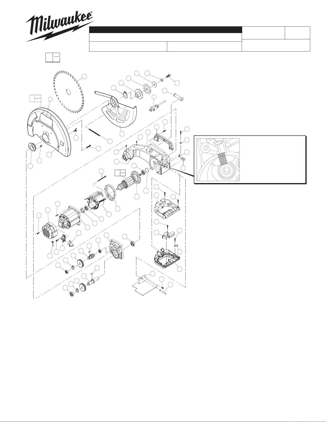
SERVICE PARTS LIST
EXAMPLE:
Component Parts (Small #) Are Included
When Ordering The Assembly (Large #).
0
00
CATALOG NO. 6190-20
REVISED BULLETIN
SPECIFY CATALOG NO. AND SERIAL NO. WHEN ORDERING PARTS
14" DRY CUT MACHINE
STARTING
SERIAL NO.
DATE
May 2014
WIRING INSTRUCTION
58-01-0575
892A
FIG. PART NO. DESCRIPTION OF PART NO REQ.
1 05-74-0040 M10 x 35 Socket Hd. Hex Screw (1)
2 45-88-1370 Split Washer (1)
3 45-88-1365 Flat Washer (1)
4 43-34-0425 Outer Flange (1)
5 43-34-0430 Inner Flange (1)
6 05-92-0085 Retaining Ring (1)
7 43-54-0405 Safety Cover Set (1)
8 06-72-1720 Service Rivet (4)
10 40-50-0045 Safety Cover Tension Spring (1)
11 05-81-0755 M5 x 35 Pan Hd. Screw (4)
12 05-89-0060 M5 x 6 Thumb Screw (1)
13 43-54-0385 Blade Cover (1)
14 05-80-0445 M4 x 10 Counter Sunk Hd. Screw (3)
15 43-56-0745 Safety Cover Guide (1)
16 22-64-0800 Cord (1)
17 44-76-0040 Cord Protector (1)
18 05-78-0030 TS5 x 20 Tapping Screw (2)
19 45-88-1025 Flat Washer (2)
20 05-74-0030 M4 x 16 Socket Hd. Hex Screw (2)
21 31-44-0170 Handle Cover (1)
22 05-92-0090 Retaining Ring (1)
23 40-50-0275 Spindle Lock Spring (1)
24 31-40-0090 Gear Housing (1)
25 05-86-0100 M4 x 10 Hex Socket Set Screw (1)
26 02-04-0060 Ball Bearing (1)
27 16-70-0530 Service Armature (1)
28 42-14-0420 Fan Guide (1)
29 05-78-0035 TS5 x 75 Tapping Screw (2)
30 18-70-0530 Service Field (1)
31 02-04-0065 Ball Bearing (1)
32 42-96-0020 Rubber Cup (1)
33 28-50-0040 Motor Housing (1)
34 05-81-0775 M5 x 30 Pan Hd. Screw (4)
35 42-92-0090 Motor Cover (1)
36 05-78-0040 TS4 x 18 Tapping Screw (2)
37 22-20-0025 Carbon Brush Holder (2)
38 22-16-0045 Carbon Brush (2)
39 40-50-0280 Brush Spring (2)
40 05-78-0045 TS4 x 12 Tapping Screw (4)
41 02-04-0085 Ball Bearing (1)
42 28-20-0210 Front Cover (1)
43 02-04-0075 Ball Bearing (1)
44 43-96-0050 Square Key (1)
45 36-14-0800 Gear Shaft (1)
46 32-75-0030 Gear (1)
47 05-92-0095 Retaining Ring (1)
48 02-04-1090 Ball Bearing (1)
49 43-96-0055 Square Key (1)
50 38-50-0095 Spindle Shaft (1)
51 32-75-0035 Gear (1)
52 02-04-0080 Ball Bearing (1)
53 31-44-0175 D-Handle Halves (1)
54 05-78-0055 TS4 x 28 Tapping Screw (2)
55 23-66-1035 Switch (Incl. 4 Screws & Star Washers) (1)
56 44-76-0045 Strain Relief (1)
57 05-78-0050 TS4 x 10 Tapping Screw (1)
58 05-78-0020 TS4 x 14 Tapping Screw (2)
59 43-54-0395 Chip Shield (1)
60 44-60-0170 Spindle Lock Pin (1)
62 05-81-0835 M4 x 12 Pan Hd. Screw (3)
107 22-84-0090 Fan with Bushing (1)
108 42-38-0125 Guard Bumper (1)
110 34-40-6180 O-Ring (1)
111 34-60-0335 Retaining Ring (1)
201 ------------- 14" Dry-Cut Blade (1)
302 10-15-2560 Logo Label (2)
303 12-99-6190 Service Nameplate (1)
FIG. LUBRICATION:
24 Place 3 to 3.25 ounces (85 - 92 grams) of Type 'Y' Grease,
No. 49-08-5270, in the gear cavity of the gear housing.
FIG. NOTES:
26 Seal to face spindle gear.
31 Seal to face armature.
32 Place in motor housing prior to inserting armature.
SERVICE TOOLS:
61-10-1025 3/8" Slide Hammer Attachment (1)
61-10-1050 1/2" Slide Hammer Attachment (1)
61-10-1075 1/4" Slide Hammer Attachment (1)
107
27
8
32
29
6
35
39
36
50
51
52
49
47
40
48
46
37
34
43
45
44
33
38
15
14
11
28
60
59
201
42
30
31
41
53
55
62
56
58
57
53
54
21
10
25
24
5
3
4
23
36
20
17
1
8
19
2
2
26
16
7
12
1
2
302
303
13
302
108
110
107
111
NOTE:
If bushing is not present in the
replacement Gear Housing
(Fig. 24), bushing from the old
Housing must be removed and
pressed into the new Housing.
View shown is with the Spindle Lock
Pin (Fig. 60), Spring (Fig. 23) and
Retaining Ring (Fig. 22) removed for
clarity of bushing spacing inside bore.
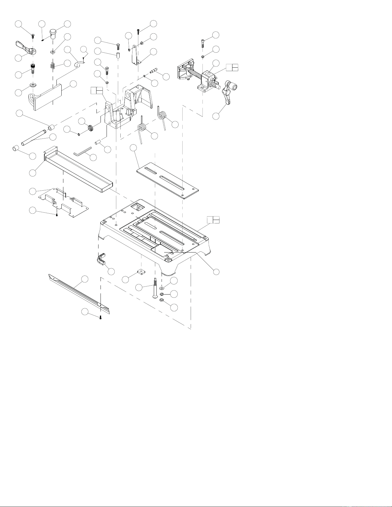
FIG. PART NO. DESCRIPTION OF PART NO REQ.
8 06-72-1720 Service Rivet (2)
63 45-84-0120 Service Vise Assembly (1)
64 45-84-0125 Vise Handle Set
(Includes two 1/4-20 Cup Point
Set Screws, No. 06-83-6035,
threaded into handle collar) (1)
65 05-74-0035 M8 x 35 Socket Hd. Hex Screw (2)
66 05-90-0030 Split Washer (6)
67 05-86-0105 M5 x 6 Hex Socket Set Screw (1)
68 43-98-0020 Fence Guide Knob (1)
69 45-88-1355 Flat Washer (2)
70 40-50-0285 Spring (1)
71 43-82-0140 Scale Indicator (1)
72 42-68-0715 Fence Guide (1)
73 05-80-0440 M6 x 12 Counter Sunk Hd. Screw (1)
74 44-10-0325 Fence Guide Lever (1)
75 42-32-0310 Fence Bolt (1)
76 45-88-1360 Flat Washer (1)
77 05-75-0010 M8 x 45 Hex Hd. Screw (1)
78 45-36-0630 Spacer (1)
79 05-75-0020 M8 x 50 Hex Hd. Screw (4)
80 05-92-0080 Retaining Ring (1)
81 31-01-0055 Transportation Lock Handle (1)
83 34-40-0030 O-Ring (1)
84 44-50-0100 Transportation Lock Pin (1)
85 05-81-0735 M5 x 20 Pan Hd. Screw (2)
86 44-60-1005 Guard Pin (1)
87 05-92-0100 Retaining Ring (1)
88 42-36-1765 Guard Linkage Bracket (1)
89 40-50-0320 Torsion Spring - Right (1)
90 40-50-0325 Torsion Spring - Left (1)
91 42-36-1745 Pivot Block with Bushings (1)
92 22-90-0205 Wrench Holder (1)
93 44-66-0210 Vise Guide Plate (1)
94 06-65-3745 Pivot Shaft (1)
95 44-54-0020 Chip Box (1)
96 44-66-0215 Chip Box Support Plate (1)
97 05-81-0745 M4 x 10 Pan Hd. Screw (8)
98 28-06-1120 Base (1)
99 05-55-0120 M10 Hex Nut (1)
100 42-32-0315 Fence Guide Bolt (1)
101 05-59-0110 Fence Guide Nut (1)
102 44-34-0210 Rubber Foot (4)
103 43-54-0350 Base Side Shield (1)
105 ------------- Bushing (20mm) Incl. with Pivot Block (1)
106 ------------- Bushing (22mm) Incl. with Pivot Block (1)
109 45-88-1370 Split Washer (1)
202 49-96-0110 8mm Wrench (1)
301 10-15-0425 Warning Label (1)
305 10-15-9460 Warning Label (1)
FIG. NOTES:
63,64 Vise handle set includes two (2) 1/4-20 cup
point set screws threaded into handle collar.
98,102 If replacing the rubber feet, 3M Scotch-Grip
®
Rubber Cement, No. 44-22-0060, must be used
to hold onto the base.
64
90
66
65
78
77
79
66
89
68
70
71
76
72
96
97
102
93
101
100
88
85
103
97
73
86
87
99
109
84
83
75
74
69
67
80
81
94
95
92
202
105
106
69
8
91
105
106
98
102
301
63
64
301
305

