1 2 3 4 5 6 7
A
B
C
D
E
F
G
H
I
J
标记 处数 分 区 更改文件号
设 计
校 对
审 核
工 艺
标准化
批 准
日 期
阶段标记
重量
比例
投影
共 张 第 页
日 期
签 字
S A B
R
法歌帝生活科技
(广东)有限公司
技术要求
1.成品尺寸:210*142mm;
2.所有尺寸公差均为±0.5mm;
3.封面封底彩色印刷,黑白印刷;
版本号
A0
封面105g 双铜纸
内页80g 双胶纸
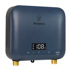
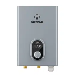
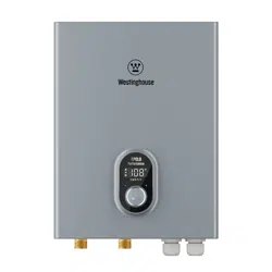
(WH)说明书
ET011K ET014K
ET018K ET024K ET027K
电即热
Electric Tankless Water Heater
WARNING
Please read all instructions before using this water heater. Failure to follow the information in these
instructions may result in fire, electric shock, property damage, injury or death.
User Manual
Products:
ET011K
ET014K
ET018K
ET024K
ET027K

CONTENTS
NOTICE
Ÿ SAVE THESE INSTRUCTIONS.
Ÿ As the appliance undergoes upgrades, there may be differences between the actual appliance and
the one described in the manual, so the content is subject to change without prior notice. Please
consult the actual product.
2.3 Technical Parameters
1.1 Safety Definitions
2.1 Function Introduction and Explanation
1 Safety Information
1.3 Important Safety Messages
2 General Information
1.2 General Information
2.2 Dimensions and Connection Points
3.2 Prepare for Installation
3.3 Installation Dimensions
3.5 Water Connections
3.6 Electrical Connection
3.7 Commissioning the Water Heater
4 Operation
4.1 Operation Instructions
2.4 Component Diagram
5 Maintenance
3.4 Installation Method
6 Troubleshooting
3 Installation
6.1 Fault Assessment and Troubleshooting
6.2 Diagnostic Codes
3.1 Installation Instructions
8 Packing List
7 Circuit Diagram
Warranty Policy
04
04
04
04
05
06
05
07
10
10
11
12
11
14
16
08
17
17
18
13
19
19
20
21
22
23
1 Safety Information
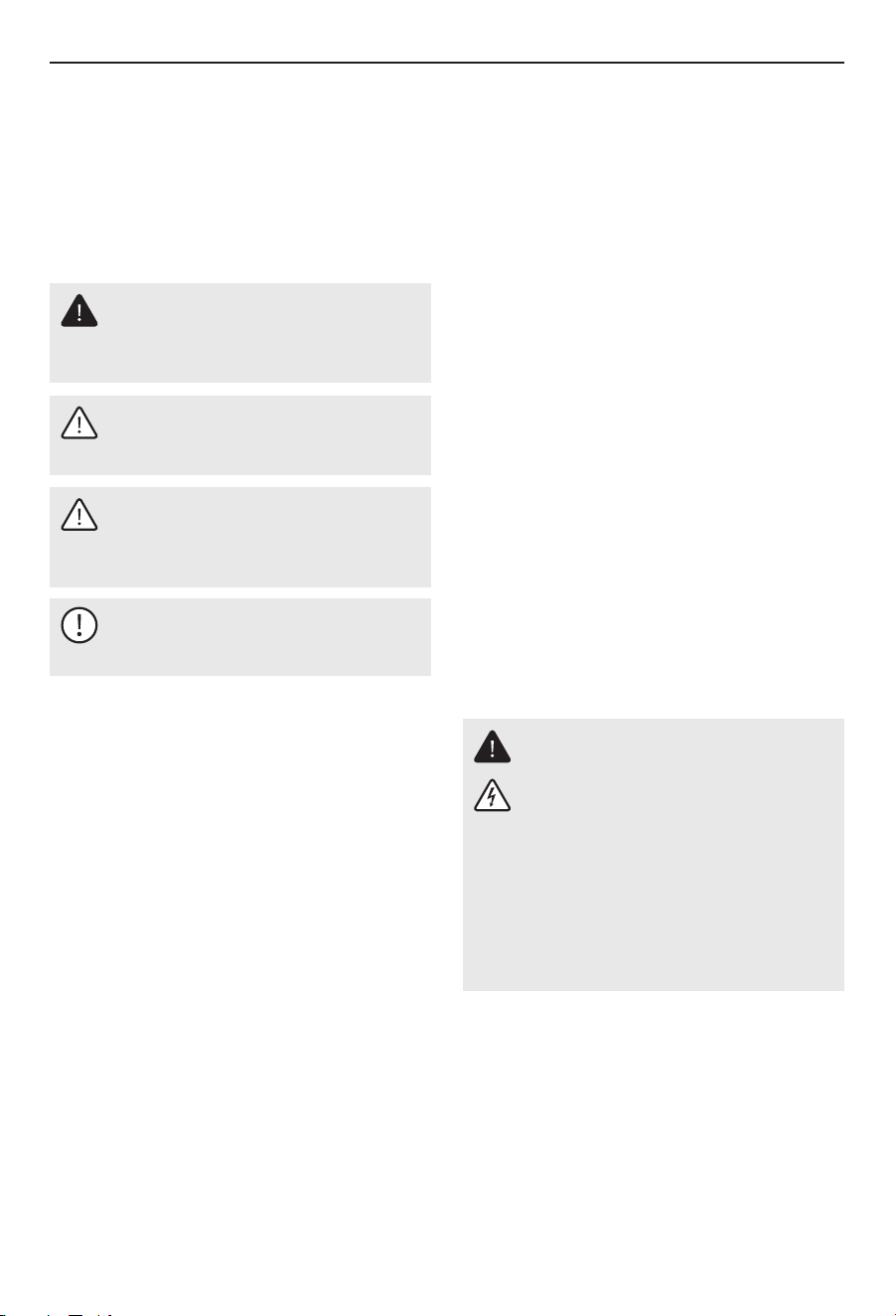
1.1 Safety Definitions
This manual has safety information and instructions
to help you eliminate or reduce the risk of accidents
and injuries.
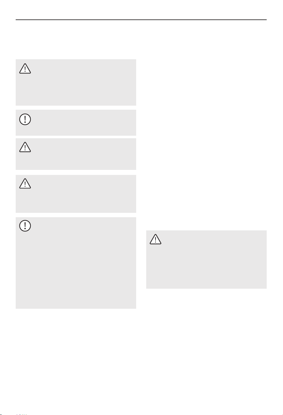
CAUTION
Indicates a hazardous situation which, if not
avoided, could result in property damage and
minor or moderate injury.
WARNING
Indicates a hazardous situation that, if not
avoided, could result in death or serious injury.
DANGER
Indicates an imminently hazardous situation
which, if not avoided, will result in death or
serious injury.
NOTICE
This symbol indicates important information
where there is no risk to people or property.
Safety Information
1.2 General Information
04
Ÿ Improper installation, adjustment, alteration,
service and use of this unit can result in serious
injury.
Ÿ Read this entire manual. Failure to follow all the
guides, instructions and rules could cause personal
injury or property damage.
Ÿ The installation must comply with all national, state
and local plumbing and electric codes. Proper
installation is the responsibility of the installer.
Failure to comply with the installation and
operating instructions or improper use voids the
warranty.
Ÿ This unit must be installed by a licensed electrician
and plumber.
Ÿ Save these instructions for future reference. The
installer should leave these instructions with the
consumer.
Ÿ If you have any questions regarding the installation,
use or operation of this water heater, or if you need
any additional installation manuals, please call our
technical service line.
1.3 Important Safety Messages
Observe the following safety information and
regulations.
Operate the appliance only when fully installed and
with all safety equipment fitted.
1.3.1 Intended Use
Observation of these instructions is also part of the
correct use of this appliance.
The appliance is intended for heating domestic hot
water and can supply several draw-off points.
Any other use beyond that described shall be deemed
inappropriate, and may void the manufacturers
warranty.
1.3.2 Safety Precautions
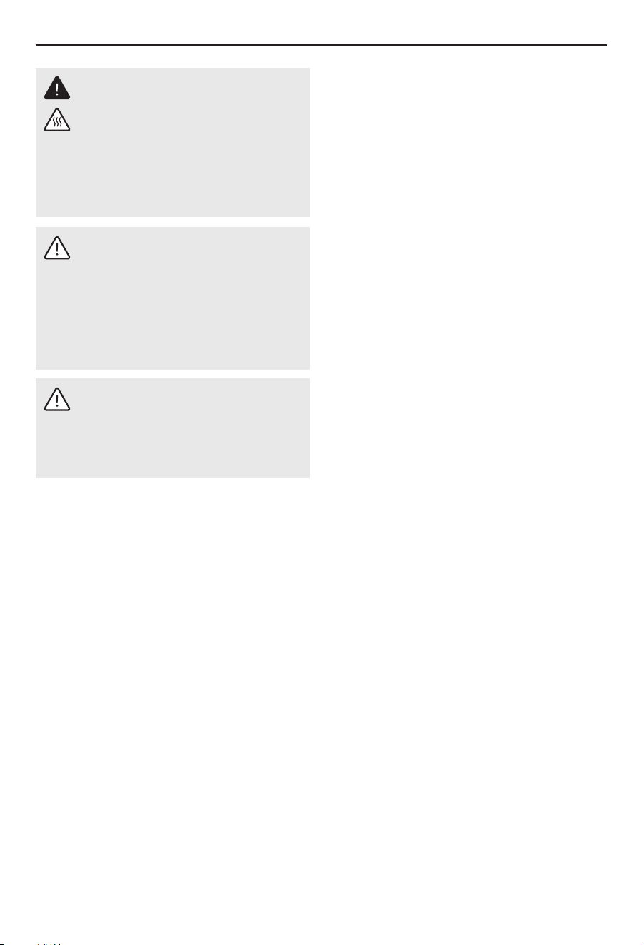
DANGER: Electrocution
The appliance must be properly grounded.
Failure to electrically ground the product could
result in serious personal injury or death.
Before proceeding with any installation,
adjustment, alteration, or service of this
appliance, all circuit breakers and disconnect
switches servicing the appliance must be
turned off. Never remove the appliance's cover
unless the electricity servicing the appliance is
turned off. Failure to do so could result in
personal injury or death.
General Information
05
2 General Information
The units are designed to supply hot water for a
house, apartment or certain commercial
applications.
Unlike a conventional storage type water heater, the
units tankless water heater does not store hot water.
Instead, water is heated instantaneously as it flows
through the unit. The units offers greater energy
efficiency than storage type water heaters due to the
absence of stand-by losses and reduced hot water
pipe runs.
The input of heat into the water is controlled
electronically. The units will deliver any water
temperature between 68 °F (20 °C) and 140 °F (60 °C).
Set the desired temperature using the knob on the
front cover. The units temperature adjustment knob
can be set to: OFF, 68-140 °F (20-60 °C). The
maximum temperature is electronically limited to
140 °F (60 °C).
For reasons of appliance efficiency and durability
(scaling), the optimum temperature setting lies
between 86 °F (30 °C) and 120 °F (50 °C).
WARNING
This product can expose you to lead, which is
known to the state of California to cause
cancer and birth defects or other reproductive
harm. For more information, go to
www.P65warnings.ca.gov.
DANGER: Burns
Water temperatures over 125°F (52°C) can
cause severe burns instantly or death from
scalding. A hot water scalding potential exists
if the thermostat on the appliance is set too
high. Households with small children, disabled
or elderly persons may require that the
thermostat be set at 113°F (45°C) or lower to
prevent possible injury from hot water.
WARNING: injury
Where children or persons with limited
physical, sensory or mental capabilities are to
be allowed to control this appliance, ensure that
this will only happen under supervision or after
appropriate instructions by a person
responsible for their safety. Children should be
supervised to ensure that they never play with
the appliance.
1.3.3 Test Symbols
See the type label on the appliance.
1.3.4 Licences / certificates
- UL (U.S.A) Std. 499
- CSA (Canada) Std. C22.2 No.88
- NSF/ANSI 372
2.1 Introduction and Explanation
General Information
06
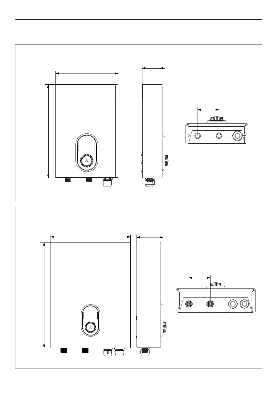
ET018K/ET024K/ET027K
3.5" (89 mm)
ET011K/ET014K
2.2 Dimensions and Connection Points
9.5" (242 mm)
3.26" (83 mm)
14.2"
(362 mm)
3.5" (88 mm)
4.3" (109 mm)13" (329 mm)
17"
(434 mm)
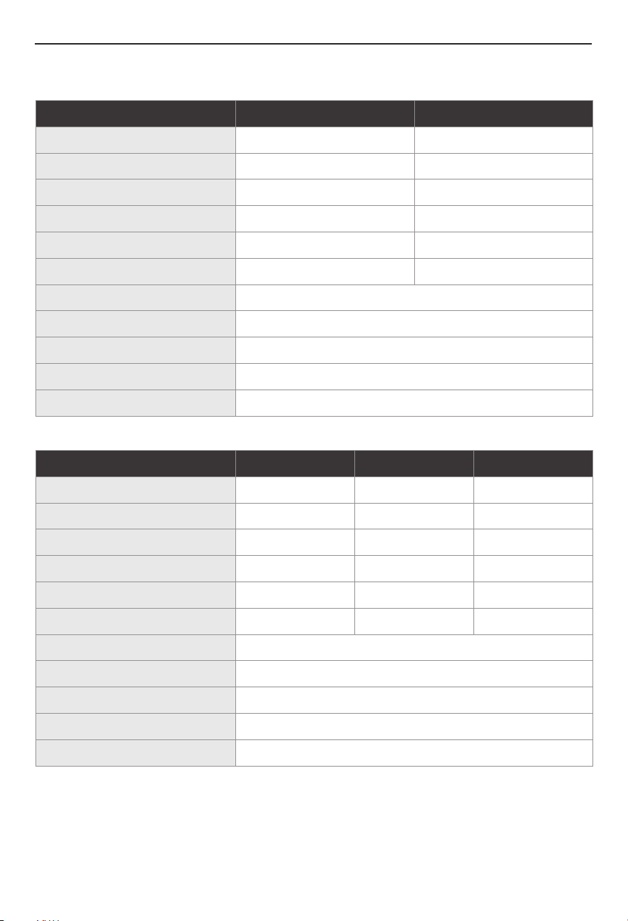
2.3 Technical Parameters
Model
Voltage
Wattage
Max. Amperage
Min. Required Circuit Breaker Size
Recommended Wire Size
0.4 GPM / 1.5 L/min 0.5 GPM / 1.8 L/min
Min. Water Flow to Activate the Unit
3 PSI - 120 PSI
Water Connections
1/2" NPT
Safe Operating Pressure
Installation
Wall mounted
Temperature Setting
Digital Panel
14.2" × 9.5" × 3.5" (362 × 242 × 89 mm)
Dimensions (H × W × D)
ET011K ET014K
240 V
11 kW
1 X 50 A
46 A
1 X 8 AWG
240 V
14 kW
1 X 60 A
59 A
1 X 6 AWG
Model
Voltage
240 V
Wattage
18 kW
ET018K
2 X 40 A
Max. Amperage
75 A
Min. Required Circuit Breaker Size
Recommended Wire Size
2 X 8 AWG
0.66 GPM / 2.5 L/min
Min. Water Flow to Activate the Unit
3 PSI - 120 PSI
Water Connections
3/4" NPT
Safe Operating Pressure
Installation
Wall mounted
Temperature Setting
Digital Panel
17" × 13" × 4.3" (434 × 329 × 109 mm)
Dimensions (H × W × D)
ET024K ET027K
240 V
24 kW
3 X 40 A
100 A
3 X 8 AWG
240 V
27 kW
3 X 40 A
113 A
3 X 8 AWG
0.79 GPM / 3.0 L/min 0.79 GPM / 3.0 L/min
General Information
07
General Information
08
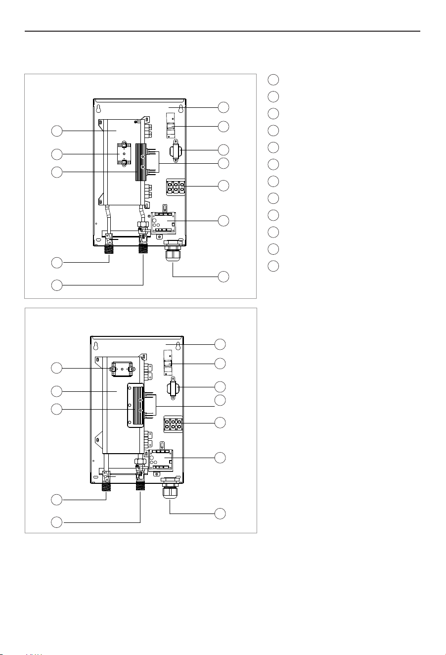
2.4 Component Diagram
ET011K
ET014K
1
2
3
5
6
4
7
8
9
12
10
11
Heating element
Thermostat
Cooling fin
Hot water connection
Cold water connection
Bottom case
Wave filter
Transformer
Silicon controlled rectifier
Terminal block
Control board
Cord clamp
1
2
3
5
6
4
7
8
9
12
10
11
1
2
3
5
6
4
7
8
9
12
10
11
General Information
09
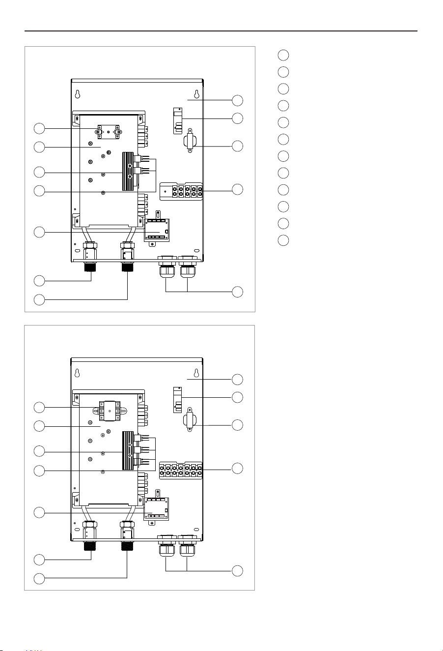
ET018K
ET024K/ET027K
1
2
3
5
6
4
7
8
9
12
10
11
Thermostat
Heating element
Cooling fin
Silicon controlled rectifier
Control Key
Hot water connection
Cold water connection
Bottom case
Wave filter
Transformer
Terminal block
Cord clamp
1
2
3
5
4
6
7
8
11
9
10
12
1
2
3
5
4
6
7
8
11
9
10
12
3 Installation
Installation
10
CAUTION
The water heater should not be located in an
area where leakage will result in damage to the
area adjacent to it or to lower floors of the
structure. Where such areas cannot be
avoided, it is recommended that a suitable
catch pan, adequately drained, be installed
under the water heater.
3.1 Installation Instructions
WARNING
Ÿ Installation must comply with the National
Electrical Code, local electrical and plumbing
codes.
Ÿ High voltage electrical installations should
be prioritized by professional electricians.
NOTICE
Unit must be installed in a vertical position
with the water fittings pointing downward.
WARNING
Do not install unit where it would routinely be
splashed with water. Electric shock may
result.
CAUTION
Hot water outlet pipes leaving unit can be hot
to the touch. Insulation must be used for hot
water pipes below 36" (0.9 m) due to burn risk
to children.
NOTICE
The unit should be located in an area where
water leakage from the unit or connections
will not result in damage to the area adjacent
to the unit. If such a location cannot be
avoided it is recommended that a drain pan be
installed under the unit.
This unit should not be installed in a location
where it may be exposed to temperatures less
than 36 °F (2 °C). If the unit may be subject to
freezing temperatures all water must be
drained from the unit. Failure to comply with
this instruction voids all warranties.
Ÿ The unit must be installed in a circuit suitable for
overcurrent. Must be grounded at the breaker
panel.
Ÿ Make sure the product is intact and complete with
accessories.
Ÿ Please ensure that the main power supply, water
pressure, grounding conditions, ammeter and
wires meet the installation requirements.
Ÿ Do not install the unit in the place of fire or strong
magnetic field. This unit needs to be installed
vertically. This unit should be connected to water
first and then to electricity.
Ÿ This unit must be permanently connected to a fixed
circuit breaker. If you are not using the unit, turn off
the circuit breaker.
Guidelines You Need to Be Aware of
Ÿ This unit is designed for indoor installation only.
However, it may be installed in an outdoor location
as long as it is mounted in a suitable enclosure that
provides protection from rain, splashed water,
freezing temperatures, direct sunlight, debris, and
insects.
Ÿ Install unit as close as possible to the main hot
water draw off points.
Ÿ Install unit in a frost free area. If frost might occur,
remove unit before freezing temperatures set in.
Ÿ Leave a minimum of 5" (120 mm) of clearance on all
sides for servicing.
Ÿ DO NOT install under water pipes or air conditioning
lines that might leak or condense moisture that
could then drip onto the unit.
Ÿ DO NOT install above electrical boxes or junctions.
Installation
11
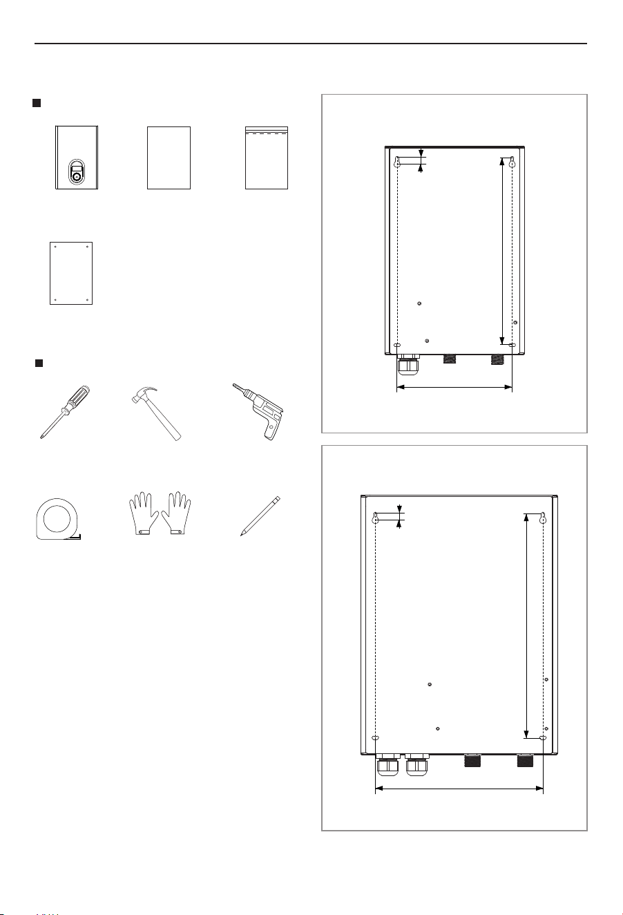
3.2 Prepare for Installation
Parts included
Water Heater User Manual Assembly Kit
Tools needed (Not included)
Phillips
screwdriver
Gloves
Hammer Drill
With Concrete Bits
Ruler Pencil
Hammer
Mounting template
3.3 Installation Dimensions
ET018K/ET024K/ET027K
ET011K/ET014K
7.88" (200 mm)
12.87" (327 mm)
11" (280 mm)
14.78" (375.5 mm)
0.5" (11 mm)
0.5" (11 mm)
Installation
12
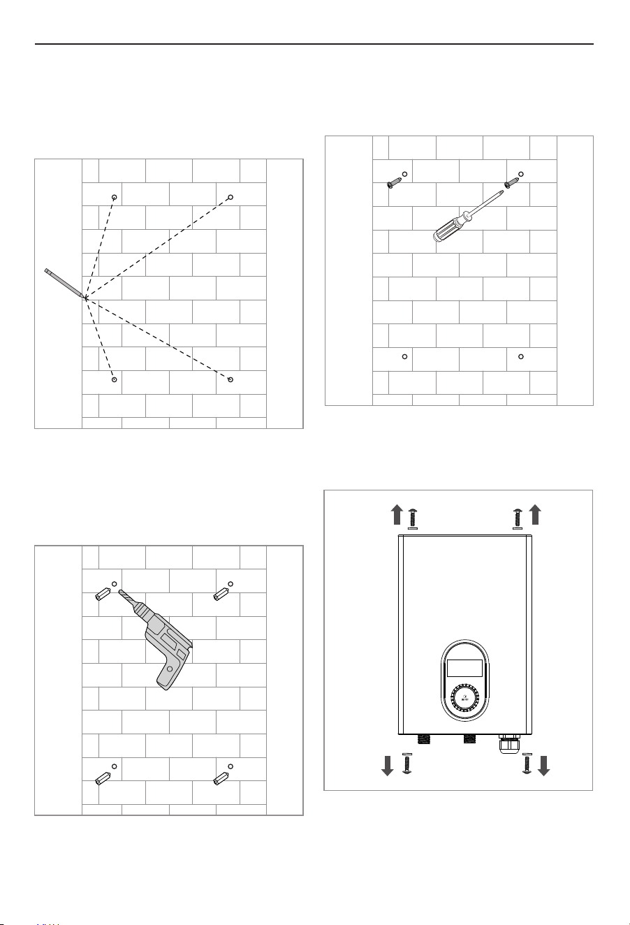
Fig.4
3.4Installation Method
4. Use a screwdriver to remove the four screws at
the top and bottom, then open the front cover
(Fig.4).
1. Figure out where to mount the water heater unit,
mark 4 mounting holes on the wall according to the
water heater or installation guide. (Fig.1).
Fig.1
Fig.2
2. Use a hammer drill with concrete bits to create a
hole in the wall according to the punching mark,
ensuring it is 0.24" (6mm) in diameter and 1.02-
1.1"(26-28mm) in depth. Then, insert the matching
4-M4 plastic wall anchors into the hole (Fig.2).
Fig.3
3. Insert M4 screws into the two upper holes, leaving
about 0.12 inches to 0.2 inches (3-5mm) not tightly
fastened (Fig.3).
Installation
13
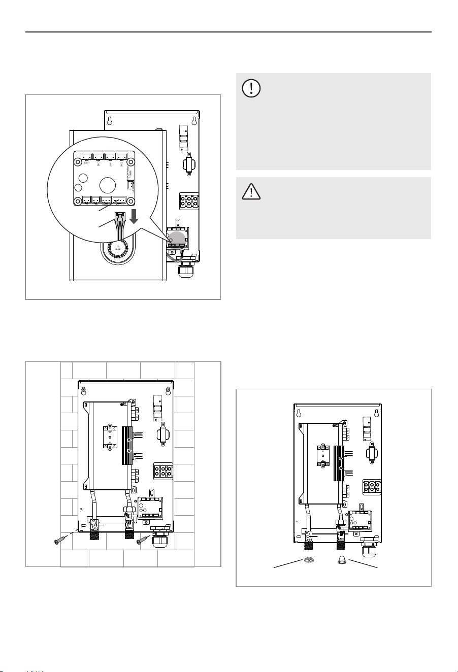
Fig.6
6. Hang the unit on the two screws installed
previously, secure the two lower screws, and
tighten the two upper screws (Fig.6).
3.5 Water Connections
NOTICE
The cold water connection to the unit must be
disconnected periodically in order to clean the
filter screen. It is required to use water
connections that are easily detachable such
as braided steel flex connectors.
Excessive heat from soldering on copper pipes
near the Unit may cause damage.
CAUTION
Hard water or water with a high mineral count
may damage the unit. Damage to the unit
caused by scale or a high mineral count is not
covered under the warranty.
Ÿ A pressure reducing valve must be installed if the
cold water supply pressure exceeds 150 PSI (10
bar).
Ÿ Make certain that the cold water supply line has
been flushed to remove any scale and dirt.
Ÿ All plumbing work must comply with national and
applicable state and local plumbing codes.
Ÿ The unit has a built in filter screen that should be
cleaned from time to time. Clean screen and put the
screen and the washer back into their original
position.
Ÿ The cold water connection (inlet) is on the right side
of the unit, and the hot water connection (outlet) is
on the left side of the unit.
Washer
Filter screen
5. For easier installation, carefully unplug ① the
display connect wire from ② the water heater
connector (Fig.5).
Fig.5
①
②
7. After completing all plumbing and electrical
connections, reconnect the display cable to the
water heater connector, install the front cover and
tighten the four upper and lower screws with a
screwdriver.
Installation
14
3.6 Electrical Connection
WARNING: Electrocution
Before beginning any work on the electric
installation, be sure that main breaker panel
switches are "Off" to avoid any danger of
electric shock. All mounting and plumbing
must be completed before proceeding with
electrical hook-up. Where required by local,
state or national electrical codes the circuits
should be equipped with a "ground fault
interrupter".
The unit must be properly grounded in
accordance with state and local codes, or in
absence of such codes, in accordance with
national electric code or the Canadian electric
code. Failure to electrically ground the product
could result in serious personal injury or death.
Ÿ The unit should be connected to properly grounded
dedicated branch circuits of proper voltage rating.
Ground must be brought to the "Ground" at the
circuit breaker panel.
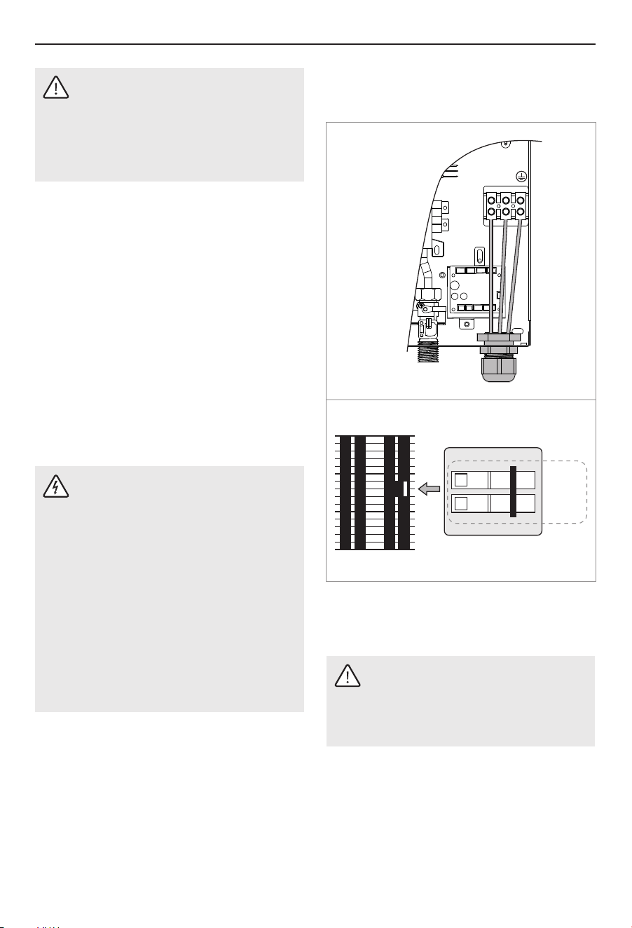
3.6.1 Circuit Layout
ET011K/ET014K
OFFOFF
ONON
ET011K/ET014K: These units can be connected to a
single circuit. Use a supply cable protected by a
double pole breaker.
L1
L2
WARNING
Ÿ ET011K and ET014K must be connected to 1
sets of 240V power. Each set power needs
to be connected to a two-pole breaker.
Ÿ L1 & L2 must be connected to breaker A.
Breaker
A
CAUTION
Tankless water heaters are not required to be
equipped with a temperature and pressure
relief valve (T&P). If the local inspector will not
pass the installation without a T&P, it should
be installed on the hot water outlet side of the
unit.
Ÿ The unit on the hot side is designed for connection
to copper tubing, PEX tubing or a braided stainless
steel hose with a female tapered thread.
Ÿ The plumbing on the cold water inlet side needs to
be such that it can easily be removed to allow
access to the inlet filter screen. The easiest way to
achieve this is to us a stainless steel braided hose
connector. If soldering near the unit is necessary,
please direct the flame away from the housing of
the unit in order to avoid damage.
Ÿ When all plumbing work is completed, check for
leaks and take corrective action before proceeding.
OFFOFF
ONON
Installation
15
OFFOFF
ONON
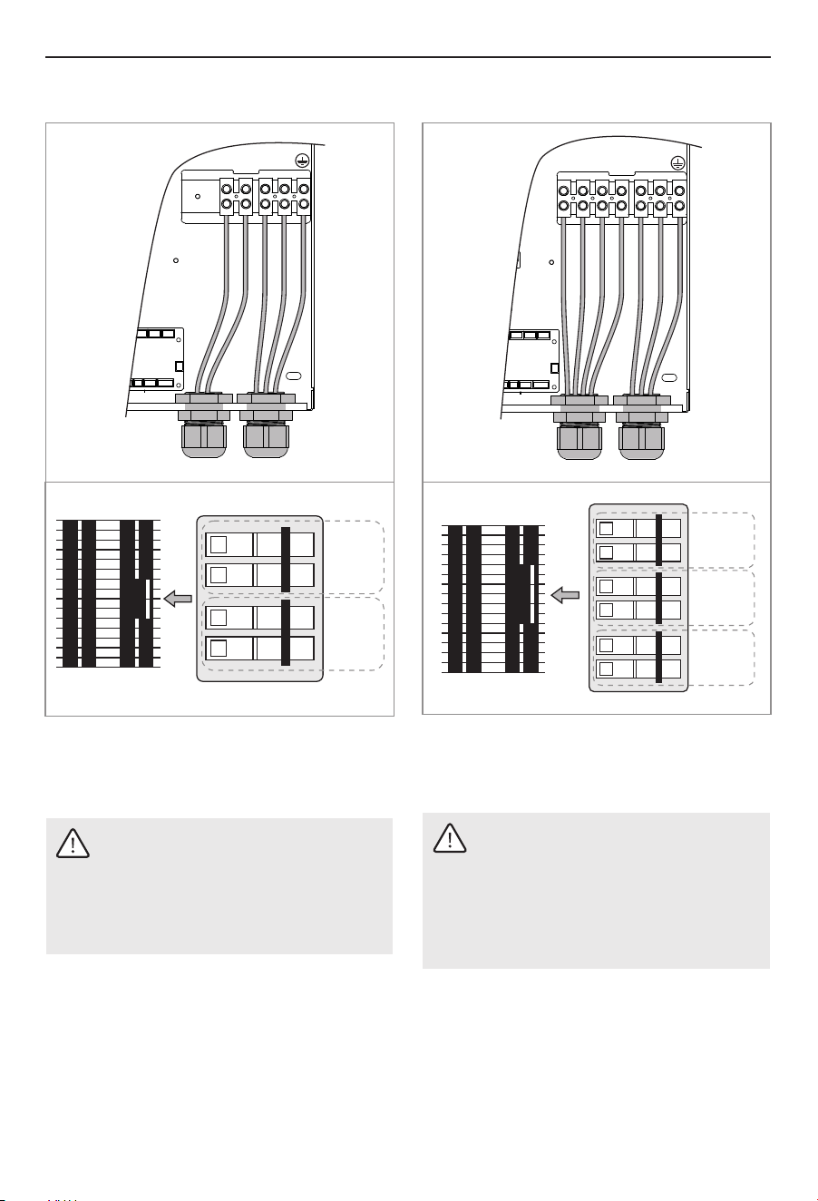
ET018K: These units require two independent circuits.
Use two supply cables protected by two separate
double pole breakers.
WARNING
Ÿ ET018K must be connected to 2 sets of
240V power. Each set power needs to be
connected to a two-pole breaker.
Ÿ L1 & L2 must be connected to breaker A, L1’ &
L2’ must be connected to breaker B.
ET024K/ET027K
L1
L2
L1'L2'L1"L2"
OFFOFF
ONON
OFFOFF
ONON
ET024K/ET027K: These units require three
independent circuits. Use two supply cables
protected by three separate double pole breakers.
WARNING
Ÿ ET024K and ET027K must be connected to 3
sets of 240V power. Each set power needs
to be connected to a two-pole breaker.
Ÿ L1 & L2 must be connected to breaker A, L1’
& L2’ must be connected to breaker B, L1" &
L2" must be connected to breaker C.
OFFOFF
ONON
ET018K
L1
L2
L1'L2'
Breaker
A
Breaker
B
Breaker
A
Breaker
B
Breaker
C
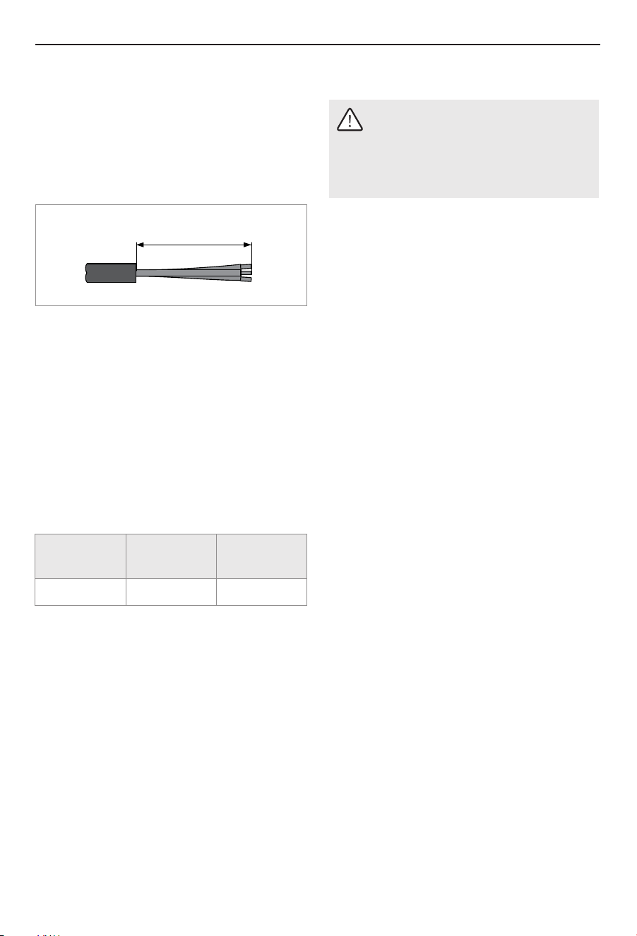
3.6.2 Circuit Connection
Please refer to "2.3 Technical Parameters" for the
correct wire and circuit breaker size. In all cases, make
sure that the unit is properly grounded.
Installation
16
Ÿ Cut the electrical connection cable to length and
strip.
15" (380 mm)
The wire must be fed through the Cord clamp (See
"3.6.1 Circuit Layout"). The "live" wires must be
connected to the slots on the terminal block marked
L1 and L2. The ground wire must be connected to slot
marked with the ground symbol (See "7 Wiring
Diagrams").
3.6.3 Terminal Block
Consult the chart below for the recommended torque
amounts on the terminal block screws.
Screw Size
(mm)
M4
Min. Torque
(N•cm)
100-140
Min. Torque
(lbf•in)
8.9-12.4
Using the proper torque specifications to secure wire
to the wiring block helps to avoid personal loss or
property damage.
3.7 Commissioning the Water Heater
WARNING
Open the hot water faucet for a few minutes
until water flow is continuous and all air is
purged from water pipes. The unit’s cover
must be installed before the circuit breakers
are turned on.
Ÿ Explain to the user how the unit works and
familiarize them with its use.
Ÿ Close the cover and fix it using the screw with the
lock washer.
Ÿ Adjust the water temperature to the desired level
using the knob on the front cover of the unit.
Ÿ Fill the unit up completely with water.
Ÿ Turn on circuit breakers to bring electrical power to
the unit.
Ÿ Turn on hot water and wait twenty seconds until
temperature has stabilized.
Ÿ Check the water temperature with your hand and
make sure that it does not feel too hot. Reduce if
necessary.
Ÿ Advise the user about possible hazards (hot water
temperature up to 140 °F (60 °C)). Hand over these
instructions, to be kept for future reference.
Operation
WARNING
Minors are not allowed to operate the water
heater themselves unless accompanied by a
guardian.
Ÿ If the unit is not used in winter drain out the water
completely so that the heater does not freeze.
Ÿ If the unit has been paused, you may initially get a
short burst of very hot water when you turn it on
again. Please run the water through for a few
seconds to let the temperature settle down. Please
check the hot water with your hand before taking a
shower.
Ÿ Please clean the inlet filter and the shower
periodically in order to keep a proper water flow.
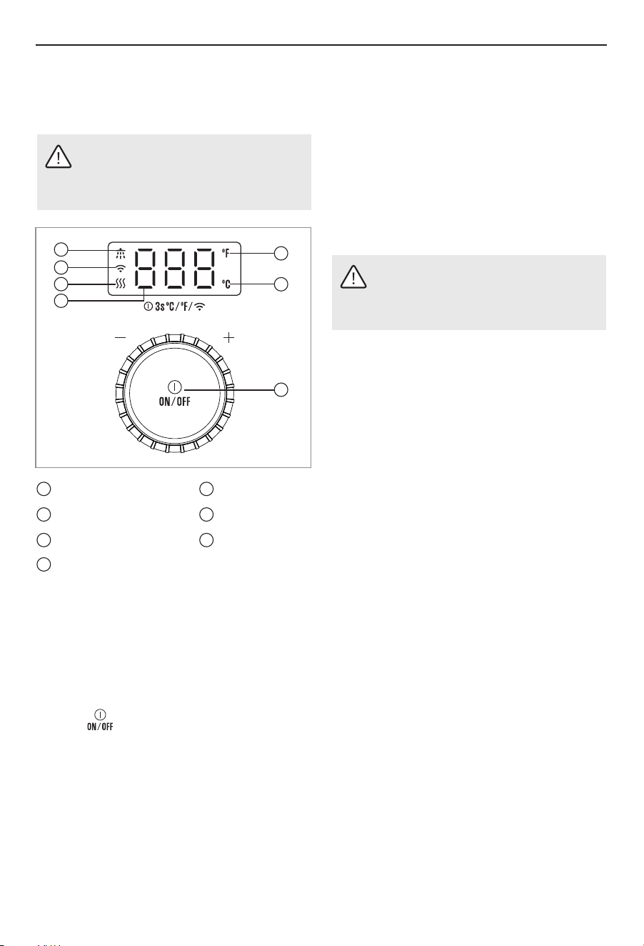
4 Operation
4.1 Operation Instructions
WARNING
Do not store or use gasoline or other flammable
vapors and liquids in the vicinity of this or any
other appliance.
3
6
Wifi icon
5
Water is heating up
Water flow signal
7
Fahrenheit
Celsius
1
2
Knob
4. Press " " to start.
2. Open the water faucet for a few minutes until the
water flow is continuous and all the air has been
purged from the water pipes.
3. After the device is powered on, there will be a
"beep" sound, and the appliance keeps standby.
5. Turning the knob clockwise increases the output
water temperature.
Temperature range is 86 - 140 °F (30 - 60°C).
6. Press the knob for 3 seconds, the display will
change from Fahrenheit to Celsius or vice versa.
Turning the knob counter clockwise decreases the
output water temperature.
1. Turn on the circuit breaker to supply electrical
power to the unit.
17
4
1
2
6
5
7
3
4
Outlet water temp

Maintenance
18
5 Maintenance
Ÿ The power supply always needs to be shut
off before these operations are carried out.
Ÿ Do not attempt to repair this water heater
yourself if the unit is not working properly.
Call a technician for assistance.
CAUTION
Ÿ Periodically remove scales and dirt that may build
up at the aerator of the faucet or in the shower
head.
Ÿ The tankless water heaters are designed for a very
long service life. Actual life expectancy will vary
with water quality and use. To ensure consistent
water flow, it is recommended to periodically
remove scale and dirt that may build up at the
aerator of the faucet(s), the filter screen in the unit,
or the heating canisters of the water heater.
Ÿ Periodically check the water quality supplied to the
water heater. Water quality can have an impact on
appliance longevity and may not be covered under
the manufacturer's warranty.
Ÿ There is a built-in filter at the inlet connection which
should be cleaned from time to time. Please cut the
water supply before doing this.
Ÿ If you live in hard water area and you get a descale
device installed prior to the tankless water heater, it
is recommended that you should annually change
the filter for the descale device, or do it according to
the instruction of its manufacturer.
3. Do not use thinner, alcohol, petrol, or any other
organic solutions to clean the set. use only a damp
cloth with mild detergent.
1. Any maintenance performed on the water heater
unit may introduce air into plumbing pipes, it is
important to purge all the air out before power on
again.
2. If you have a water supply with high level of
mineralization(hard water),you should increase the
frequency of your maintenance. Check the declare
device regularly to see if it is functional.
Important Note:
To ensure consistent Maximum performance of the
unit, it is recommended to follow these instructions:
Troubleshooting
19
6 Troubleshooting
6.1Fault Assessment and Troubleshooting
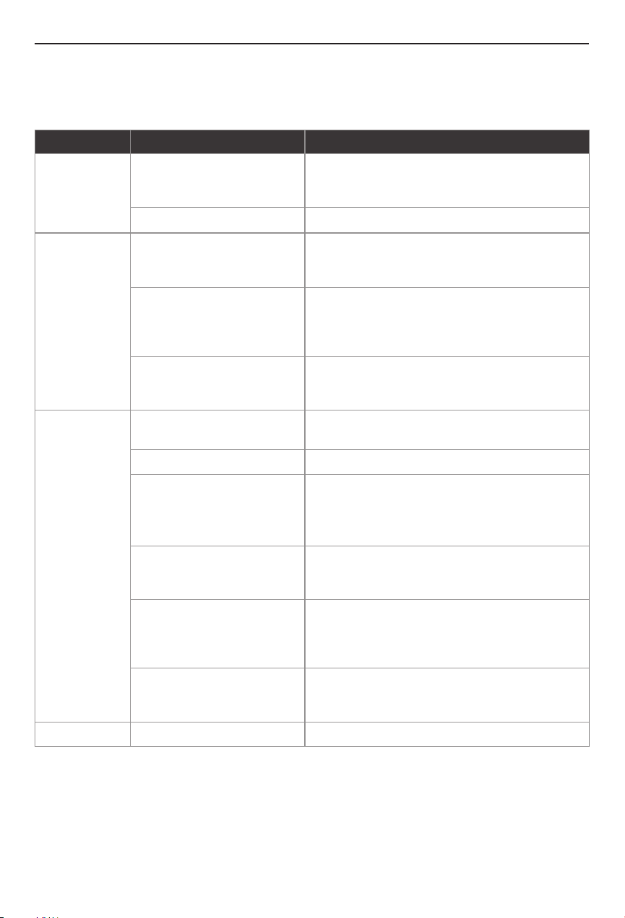
Problems
Possible Causes
Corrective Actions
Digital display is
not activated
No power or incorrect wiring
No hot water
Not enough flow
Hot water supply
is warm, but it
does not get hot
Water is too hot
No power or incorrect wiring
Overtemperature protection has
been triggered
Flow rate is too low
Temperature set point is too low
Flow rate is too high
Voltage less than 240 VAC
No power or incorrect wiring
Mixing too much cold water
Cold inlet temperature may be
lower during winter months
Temperature set point too high
Check breakers at main electrical panel to ensure it is
not tripped. If tripped, reset breaker. Check that water
heater is wired correctly.
Turn on hot water at fixture.
Check breakers at main electrical panel to ensure it is
not tripped. If tripped, reset breaker. Check that water
heater is wired correctly.
The water heater is equipped with software that turns
off the heating elements when water temperatures
reach a dangerous level. Turn off hot water, wait
several minutes for water to cool.
Each model water heater has an activation flow rate. If
the water flow is less than this flow level, unit will not
heat water. Increase the flow rate.
Increase the temperature set point, Be cautious of
scald risk.
Reduce flow rate.
The heating elements on your water heater are
designed for 240 VAC applications. When used a
lower voltage, the water heater will produce less hot
water.
Check breakers at main electrical panel to ensure it is
not tripped. If tripped, reset broker. Check that water
heater is wired correctly.
Tankless water heaters do not require mixing as much
cold water as a conventional storage water heater.
Adjust handle of fixture or mixing valve on faucet to
reduce the amount of cold water mixed.
This is normal. The colder inlet water requires more
heat to reach the temperature set point. Increase the
temperature set point.
Reduce temperature set point.
Troubleshooting
20
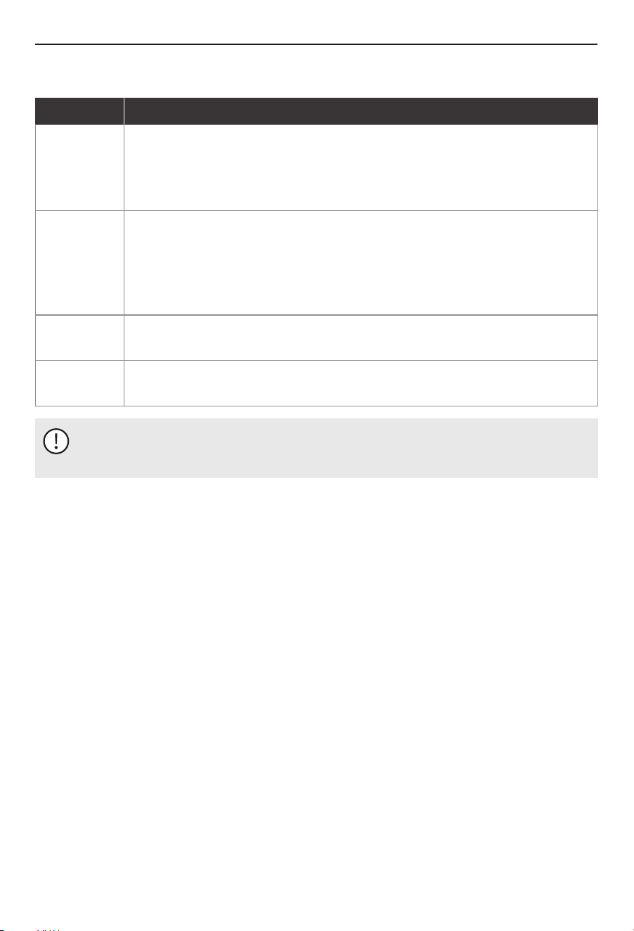
6.2 Diagnostic Codes
Error Code
E1
E3
When the outlet water temperature is <140 °F (60 °C), resume the heating operation;
After troubleshooting, power off and restart to restore.
Over temperature protection
When the outlet water temperature >158 °F (70 °C), stop working and display E1.
If the outlet water temperature is >149 °F (65 °C), stop heating;
Inlet water temperature sensor failure (after troubleshooting, power off and restart to
recover).
E4
Outlet water temperature sensor failure (after troubleshooting, power off and restart to
recover).
NOTICE
If the unit is still out of function after you have taken step above, please contact after sales service by phone
or e-mail.
Fault description and troubleshooting step
E0
Voltage Mismatch Warning: If the input voltage does not match the required voltage, the
system will display a fault code and the buzzer will sound continuously for 10 seconds. To
resolve this issue, please ensure the correct voltage is supplied.
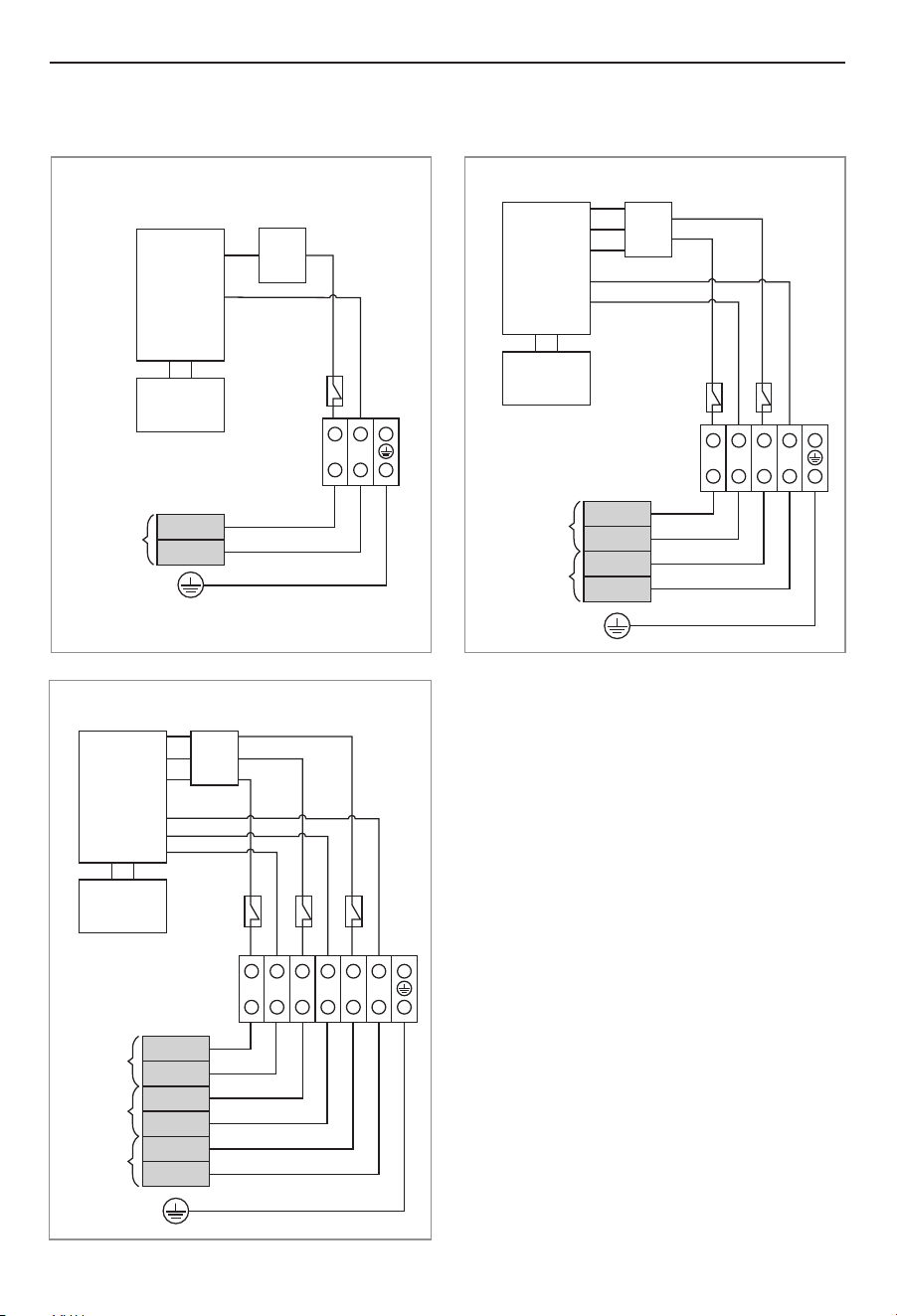
7 Wiring Diagrams
Wiring Diagrams
21
ET011K/ET014K ET018K
ET024K/ET027K
Triac
L1
L2
L1
L2
Breaker
A
Heating
element
Display
board
Triac
Heating
element
L1
L2
L1'
L2'
L1
L2
Breaker
A
L1'
L2'
Breaker
B
Display
board
Triac
Heating
element
L1
L2
L1'
L2'
L1
L2
Breaker
A
L1'
L2'
Breaker
B
Display
board
L1"
L2"
L1"
L2"
Breaker
C
Packing List
22
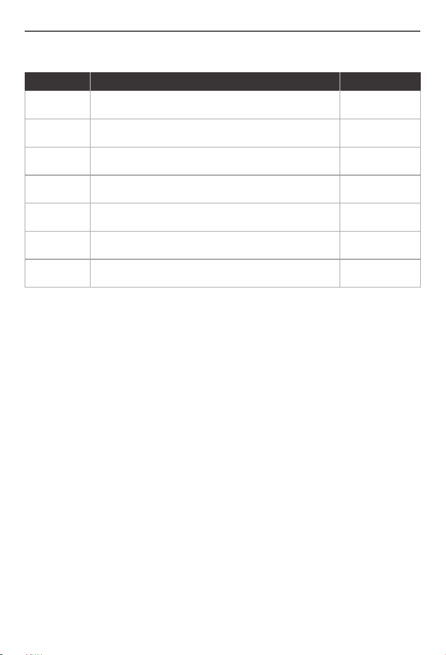
8 Packing List
Order
Design
1
Quantity
1 piece
2
The water heater
3
1 pieceInstallation and operation manual
4
1 pieceInstallation guide
5
5 piecesScrew M4 × 20
7
1 pieceInlet fliter
2 piecesRubber gasket for outlet and inlet
6
5 piecesRubber plug
23
Warranty Policy
What is covered
The Standard Limited Warranty covers any defects in materials or workmanship when the product is installed
and operated according to its written installation instructions, subject to the terms within this Limited
Warranty document. This Limited Warranty applies only to products that are installed correctly in the United
States and Canada. Improper installation may void this Limited Warranty. The supplier strongly recommends
that this tankless water heater to be installed by a contractor who is licensed, state qualified, and trained on
supplier's tankless products since improper installation may invalidate warranty coverage.
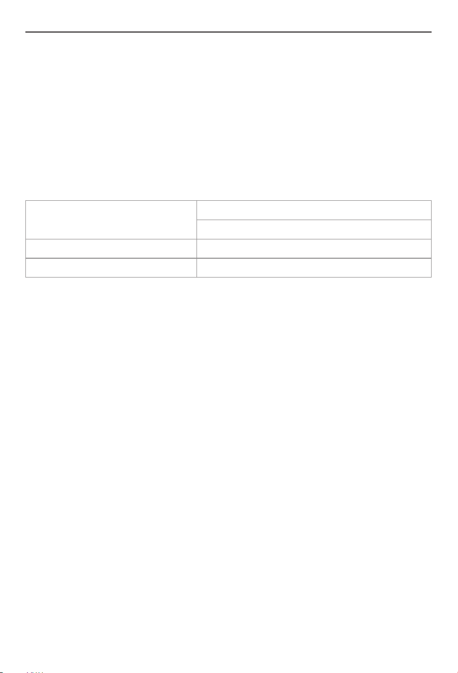
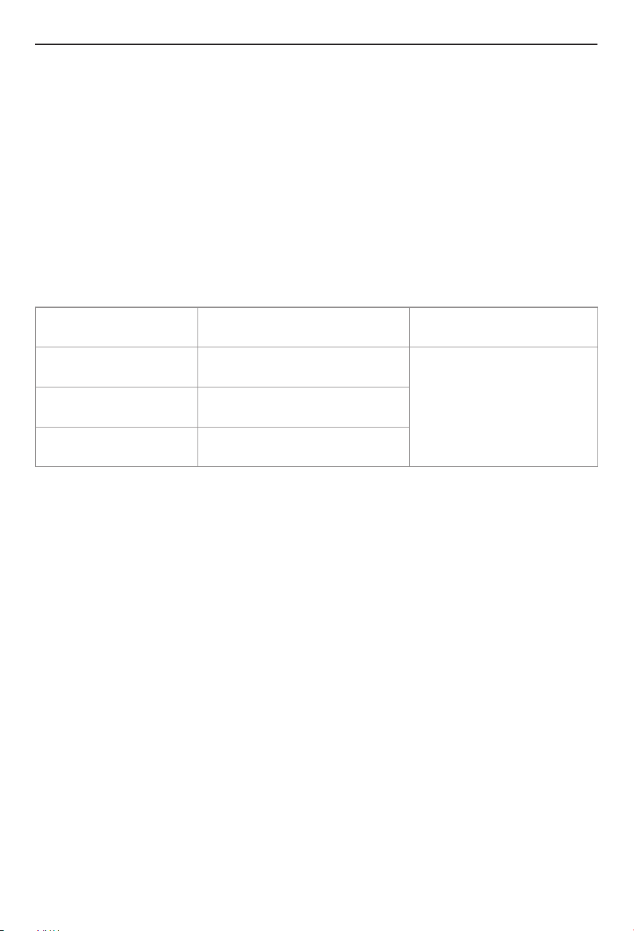
How long does coverage last
Item
All Other Parts and Components
*Shipping Costs
Period of Coverage (from date of purchase)
12 months
30 days
Residential Applications
* Which excluding Alaska, Hawaii, and any location outside of the continental US and Canada
Limitation on warranties
No one is authorized to make any other warranties on behalf of Westinghouse Corporation. Except as expressly
provided herein, there are no other warranties, expressed or implied, including, but not limited to warranties of
merchantability or fitness for a particular purpose, which extend beyond the description of the warranty herein.
Any implied warranties of merchantability and fitness arising under state law are limited in duration to the
period of coverage provided by this Limited Warranty, unless the period provided by state law is less. Some
states do not allow limitations on how long an implied Limited Warranty lasts, so the above limitation may not
apply to you. Westinghouse shall not be liable for indirect, incidental, special, consequential, or other similar
damages that may arise, including lost profits, damage to person or property, loss of use, inconvenience, or
liability arising from improper installation, service, or use. Some states do not allow the exclusion or limitation
of incidental or consequential damages, so the above limitation may not apply to you. This Limited Warranty
gives you specific legal rights, and you may also have other rights which vary from state to state.
During the Warranty Period, all repair parts must be genuine Westinghouse parts; all repairs or replacements
must be performed by a qualified professional who is professionally trained to do the type of repair. A
component in the product fails because of a manufacturing defect, Westinghouse will repair, replace, or refund
the product to the owner at Westinghouse’s sole discretion and as determined to be appropriate by the
Westinghouse Support Team.
Westinghouse does not authorize any person or company to assume for it any obligation or liability in
connection with the replacement of the product. If Westinghouse determines that repair of a product is not
possible, Westinghouse may replace the product with a comparable product at Westinghouse’s sole discretion.
The warranty claim for product parts and labor may be denied if a component or product returned to
Westinghouse is found to be free of defects in material or workmanship; damaged by improper installation, use
or operation; or damaged during return shipping.

24
How To Obtain Service
All shipments of any type of product coming to Westinghouse for any reason must have a Return Goods
Authorization (“RGA”) number for any repairs to be made. Please contact Westinghouse to obtain an RGA
number prior to shipping anything to Westinghouse. Failure to do so could result in loss of product.
Westinghouse will not be responsible for replacement due to loss or damage if above steps are not properly
followed.
To make a warranty claim through this Limited Warranty, the owner must contact Westinghouse’s Customer
Service team at[email protected], schedule a call or live chat on the Westinghouse Whatsapp. It
is within Westinghouse’s sole discretion when a repair, replacement, or refund will be issued. Any return for
refund must be approved by Westinghouse’s Customer Service team prior to shipping the product back to
Westinghouse. Please refer to Returning Your Product for Repair or Refund Policy provided with the Product.
Within the first 30 days of purchase, Westinghouse will cover all ground shipping costs for warranty related
issues in the US and Canada, excluding Alaska, Hawaii, and any location outside of the continental US and
Canada. After the first 30 days of purchase, the owner is responsible for all shipping to Westinghouse,
regardless of reason or circumstance. Westinghouse will cover the warranty related shipping costs when
returning the product to the owner after repair/inspection. The method for warranty related shipping will be
ground equivalent with the provider within Westinghouse’s sole discretion.
What information you will need for processing of your warranty claim:
Ÿ Proof of purchase
Ÿ Serial numbers
Ÿ Photos of the installation
Ÿ Photos of the damage part (if there is one)
Any returns to Westinghouse must be sent in the original packaging.If your returned product does not have the
original packaging and/or is missing any of the components that came with the product, there will be a
nonnegotiable 15% restock fee.
What Is Not Covered
1. A repair, replacement, or refund will not be provided under this Limited Warranty unless the Product
containing the defective component is properly installed and maintained according to Westinghouse’s
Installation Manual and Use & Care Manual and in compliance with all applicable federal, state/province, and
local laws, regulations, codes, policies, and licensing requirements. Any abuse, misuse, alteration, neglect, or
misapplication of the product will void this Limited Warranty.
3. Westinghouse systems is not responsible for any expenses arising from labor services, including but not
limited to, installation or removal services due to a warranty claim.
5. A repair, replacement, or refund will not be provided if the product is damaged because of improper use,
including freezing within the unit or surrounding piping, incorrect sizing for the application, scale build up, or
incorrect gas and/or water pressure.
2. A repair, replacement, or refund will not be provided if the product is damaged by services performed by third
party service providers other than Westinghouse Systems.
The following exclusions apply to this Limited Warranty:
4. A repair, replacement, or refund will not be provided if the product is damaged because of improper
installation, including sizing, length, elevation, condensation drainage, or inadequate airflow.
25
9. Westinghouse will not pay increases in electricity for any reason whatsoever, including additional or unusual
use of supplemental electrical heat.
7. A repair, replacement, or refund will not be provided if the product is damaged by the use of non-potable,
untreated or poorly treated well water, or water with high PH levels or hardness levels in excess of 12 grains
per gallon (200 mg/L).
8. A repair, replacement, or refund will not be provided under this Limited Warranty if the original serial number
on the product has been removed or altered in a way that causes the serial number to not be readily
determined.
6. This product shall not be used as a pool or spa heater. Use of the Product as a pool or spa heater shall be
considered misuse and will void this Limited Warranty.
10. Westinghouse will not be responsible for any default or delay in performance under this Limited Warranty
caused by any factor or contingency outside of its control.
The water heater Serial number
Product name
Product model
Purchasing date


Tel: +1 833 566 1779
Email:support@tl.westinghouse.com
and Westinghouse are trademarks of Westinghouse Electric Corporation.
Used under license by Fogatti Holdings Limited.