INSTALLATION AND
OPERATING
High-efficiency
Condensing Boiler
110,000 Btu/hr
150,000 Btu/hr
199,000 Btu/hr
(Natural Gas or Propane)
WARNING
If the information in this manual is not followed exactly, a fire or explosion may result causing
property damage, personal injury, or loss of life.
Do not store or use gasoline or other flammable vapors and liquids or other combustible
materials in the vicinity of this or any other appliance.
If you smell gas:
Do not try to light any appliance.
Do not touch any electrical switch; do not use any phone in your building.
Immediately call your gas supplier from a nearby phone. Follow the gas supplier’s
instructions.
If you cannot reach your gas supplier, call the fire department.
Installation and service must be performed by a qualified installer, service agency or the gas
supplier.

Water quality
Warning
Water quality has a significant impact on the lifetime and performance of a boiler's heat
exchanger.
Improperly prepared water in a heating circuit may cause damage to the heat exchanger
through fouling or corrosion. Repeated or uncontrolled water fills will increase the potential
for damage.
High levels of dissolved solids or minerals may precipitate out of the fluid onto the hottest part
of the heat exchanger, impairing heat transfer and resulting in overheating and premature
failure. The amount of solids that may form on the heat exchanger will depend on the degree
of hardness and the total water volume in the system. A high water volume system with a low
hardness count may cause as much damage as a system with less volume and higher
hardness, so for high-volume systems it is recommended to reduce dissolved solids to 10
ppm - 30 ppm before the introduction of inhibitors and / or glycol. Final water chemistry limits
are as follows:
Hardness to be between 1 and 9 grains
TDS is to be between 10 and 150 ppm
Acidity pH is to be between 6.6 and 8.5
Chloride is to be less than 125 mg/l
Iron is to be less than 0.3 mg/l
Cu less than 0.1 mg/l
Conductivity is to be between 20 and 300 μS/cm at 77°F (25°C)
Important: Ensure that these limits are acceptable for the other water-side components in
the system.
Shipped with the boiler:
1 x Wall mounting bracket, P-9092
1 x Condensate trap assembly, P-115
1 x 30 psig pressure relief valve, P-9009
1 x Outdoor temperature sensor, P-9067
6 x ¼" x 2 ½" Lag screws/w flat washers
1 x Propane fuel conversion kit
3
Safety information
Manual safety markings
Danger
Points out an immediate hazardous
situation that must be avoided to
prevent serious injury or death.
Warning
Points out a potential hazardous
situation that must be avoided to
prevent serious injury or death.
Caution
Points out a potential hazardous
situation that must be avoided to
prevent possible moderate injury
and/or property damage.
Note
Points out installation, maintenance
and operational notes to enhance
efficiency, longevity and proper
operation of the boiler.
Important safety instructions
Installation, start-up and servicing of the boilers must be performed by competent, qualified, licensed
and trained heating technicians.
Failure to read and comply with all instructions and applicable national and local codes may result in
hazardous conditions that could result in property damage and injury to occupants, and in extreme
cases to death. Keep instructions near the air handling appliance for future reference.
Danger
Should overheating occur or the gas supply fails to shut off, do not turn off or disconnect the
electrical supply to the pump. Instead shut off the gas supply at a location external to the
appliance.
Danger
Do not store or use gasoline or other flammable vapors or liquids in the vicinity of this or
any other appliance. If you smell gas vapors, do not try to operate any appliance - do not
touch any electrical switch or use any phone in the building. Immediately, call the gas
supplier from a phone located remotely. Follow the gas supplier’s instructions, or if the
supplier is unavailable, contact the fire department.
Warning
If the boiler is likely to be exposed to fluid temperatures below 34°F (1°C), use a method to
prevent freezing of condensate. Contact the factory for further information.
Warning
Do not use this boiler if any part has been under water. Immediately call a qualified
service technician to inspect the boiler and to replace any part of the control system and
any gas control that has been under water.
Warning
Improper installation, adjustment, alteration, service or maintenance can cause
property damage, personal injury, or loss of life. Read and understand the entire
manual before attempting installation, start-up, operation, or service. Installation and
service must be performed only by an experienced, skilled installer or service agency.
Failure to follow all instructions in the proper order can cause personal injury or death.
Read all instructions, including all those contained in component manufacturers’
manuals before installing, starting up, operating, maintaining, or servicing the
appliance.
Warning
Disconnect power supply before any wiring/service is performed. Failure to do so could
result in damage to appliance and/or electric shock.
Caution
The boiler must be installed so that electrical components are not exposed to water
during operation.
Known contaminants
Known Corrosive Contaminants to Avoid
Cements and glues Refrigerant leaks from cracks in coils
Paint or varnish removers Sodium chloride or potassium chloride used for
water softening
Adhesives used to fasten building products
and other similar products
Chemicals in perming solutions
Chlorinated waxes or cleaners Chlorofluorocarbon chemicals found in spray cans
Chlorine-based swimming pool chemicals Antistatic dryer sheets in clothes dryers
Hydrochloric acid or muriatic acid used in
household cleaning and stain removal
Chlorine-type bleaches, detergents, and cleaning
solvents found in household laundry rooms
Calcium chloride used for snow clearing
4
Section: Safety information

5
Contents
Safety information 3
Manual safety markings 3
Important safety instructions 3
Known contaminants 4
1.0 Specifications 1
Cabinet dimensions 2
Boiler Model 110 dimensions 2
Boiler Model 150 dimensions 3
Boiler Model 199 dimensions 4
Connection specifications 5
2.0 Introduction 7
2.1 Standard features and benefits 7
2.2 Warranty 8
3.0 Before installation 9
4.0 Installation 11
4.1 Code requirements 11
4.2 Removing an existing boiler 11
4.3 Determining location of the appliance 12
4.3.1 Best installation conditions 13
4.4 Mounting the boiler 14
4.5 Connecting the vent and air intake pipes 15
4.6 Installation clearances 16
4.7 Exhaust venting and air intake 16
4.7.1 Venting code 17
4.7.2 Venting options 17
4.7.3 Exhaust vent material 17
4.7.4 Direct vent 18
4.7.5 Rooftop vent termination 21
4.7.6 Sidewall vent termination 24
4.7.7 Indoor air combustion air intake 31
4.7.8 Combustion air filtration system 32
4.7.9 Using an existing vent as a chase 33
4.8 Closet installations 33

4.9 Installing a condensate trap 34
4.10 Installing a condensate neutralizer 35
4.11 Water Piping 37
4.11.1 General piping best practices 40
4.11.2 System piping 40
4.12 Gas piping 47
4.12.1 Gas pressure 47
4.13 Electrical connections 48
4.13.1 Power management, quality and electrical protection 49
4.13.2 120VAC line-voltage hook-up 49
4.13.3 Sensor and other wiring 51
4.13.4 Thermostat wiring 51
4.13.5 Thermostat heat anticipator 52
5.0 About the boiler controller 53
5.1 Controller 53
5.2 Control interface 54
6.0 Before operating the boiler 55
Important pre-ignition checks 55
Checklist for electrical conditions, ducting and water connections 55
7.0 Boiler operation 57
7.1 Lighting and shutting down the boiler 57
7.2 Testing the ignition safety shutoff 58
7.3 Commissioning 58
7.3.1 Checking a boiler's fuel source 59
7.3.2 Performing a fuel conversion 59
7.3.3 Adjusting the gas valve 60
7.3.4 Testing the LWCO function 64
7.3.5 Testing the Hi-Limit cutoff temperature function 65
8.0 Service and maintenance 67
8.1 Maintenance checklist for homeowner 67
8.2 Maintenance checklist for heating contractor 67
8.2.1 Touchscreen boiler controller 68
8.3 Torque 68
6
Section: Contents

8.4 General boiler maintenance 68
8.5 Replacing the fan, gas valve, and burner 72
8.5.1 Replacing the fan 73
8.5.2 Replacing the gas valve 74
8.5.3 Replacing the burner 75
8.6 Cleaning the sight glass 77
8.7 Cleaning the condensate trap 78
8.8 Ensure door in place 78
9.0 Troubleshooting 79
9.1 Electronic components 79
9.1.1 Temperature sensors 79
9.1.2 Fan 80
9.1.3 Water pressure sensor 80
9.1.4 Safety and Ignition Module (SIM+) 81
9.2 Troubleshooting error messages 83
9.2.1 Ignition trials exceeded error 84
9.2.2 Water High Limit error 84
9.2.3 Low Water Cut-off error 84
9.2.4 Interlock 1 or 2 error 85
9.2.5 Vent High Limit 85
9.3 Miscellaneous touchscreen controller errors 85
9.3.1 Ignition issues 87
9.3.2 Temperature issues 88
9.3.3 Miscellaneous issues 89
9.3.4 Cycling issues 90
Appendices 93
Wiring diagrams 93
Part diagrams - Boiler Model 110, Boiler Model 150, Boiler Model 199 96
Installation and Commission Report 102
7

Intentionally left empty

1
1.0 Specifications
Specification 110,000 BTU/hr 150,000 BTU/hr 199,000 BTU/hr
CSA Input (Natural Gas or Propane) 16.9 - 110 MBH 23 - 150 MBH 30.6 - 199 MBH
CSA Input (Natural Gas or Propane) 5 - 32.2 kW 6.7 - 44 kW 8.8 - 58.3 kW
CSA Output 16.2 - 101.5 MBH 22 - 138.5 MBH 29.2 - 183.7 MBH
CSA Output 4.74 - 29.8 kW 6.5 - 40.6 kW 8.6 - 53.8 kW
AFUE 95% 95% 95%
Min. gas supply pressure (NG or LP) 4 inch w.c. 4 inch w.c. 4 inch w.c.
Max. gas supply pressure (NG or LP) 14 inch w.c. 14 inch w.c. 14 inch w.c.
Minimum Ambient temperature 32°F / 0°C 32°F / 0°C 32°F / 0°C
Maximum Ambient temperature 122°F / 50°C 122°F / 50°C 122°F / 50°C
Max. relative humidity (non-
condensing)
90% 90% 90%
Minimum water temp. 34°F / 1°C 34°F / 1°C 34°F / 1°C
Max. water temp. (electronic hi-limit) 190°F / 88°C 190°F / 88°C 190°F / 88°C
Max. ΔT - supply/return (electronic
fence)
40°F / 22.2°C 40°F / 22.2°C 40°F / 22.2°C
Max. water temperature lockout limit 201°F / 94°C 201°F / 94°C 201°F / 94°C
Power use (120Vac/60Hz) @ full fire
(without pumps)
90 Watts 79 Watts 90 Watts
Weight (empty) 67 lbs / 30.4 Kg 78 lbs / 35.4 Kg 88 lbs / 39.9 Kg
Pressure vessel water content 1.88 USG/ 7.12 L 2.79 USG/ 10.56 L 3.51 USG/ 13.29 L
Maximum boiler flow rate 14 USgpm 19 USgpm 25 USgpm
Minimum boiler flow rate 2 USgpm 3 USgpm 4 USgpm
Maximum operating water pressure 50 psig 50 psig 50 psig
Minimum boiler water pressure 8 psig 8 psig 8 psig
Relief valve pressure (supplied) 30 psig 30 psig 30 psig
Approved installation altitude 0 - 12,000' ASL 0 - 12,000' ASL 0 - 12,000' ASL
Max. equiv. 2" (vent & intake each)
1
100' 50' N/A
Max. equiv. 3" (vent & intake each)
1
240' 170' 100'
CRN 9585.7CL 9415.7CL 9298.7CL
(Natural Gas Only) Meets Ultra Low
NO
x
14 ng/J requirements
Yes Yes Yes
Table 1 Boiler Specifications
1
Air intake either direct vent or indoor supply
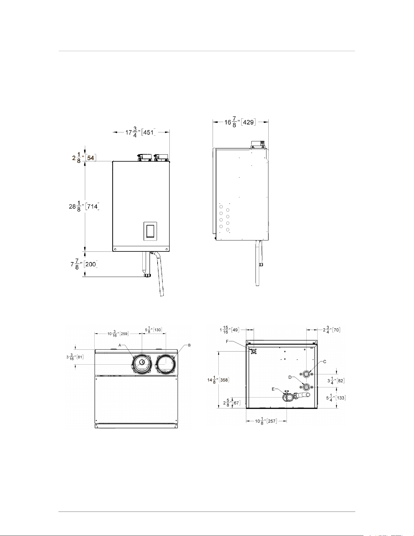
Cabinet dimensions
Boiler Model 110 dimensions
Figure 1 Frontal view - Boiler Model 110 Figure 2 Side view - Boiler Model 110
Figure 3 Top view - Boiler Model 110 Figure 4 Bottom view - Boiler Model 110
2
Section: Specifications
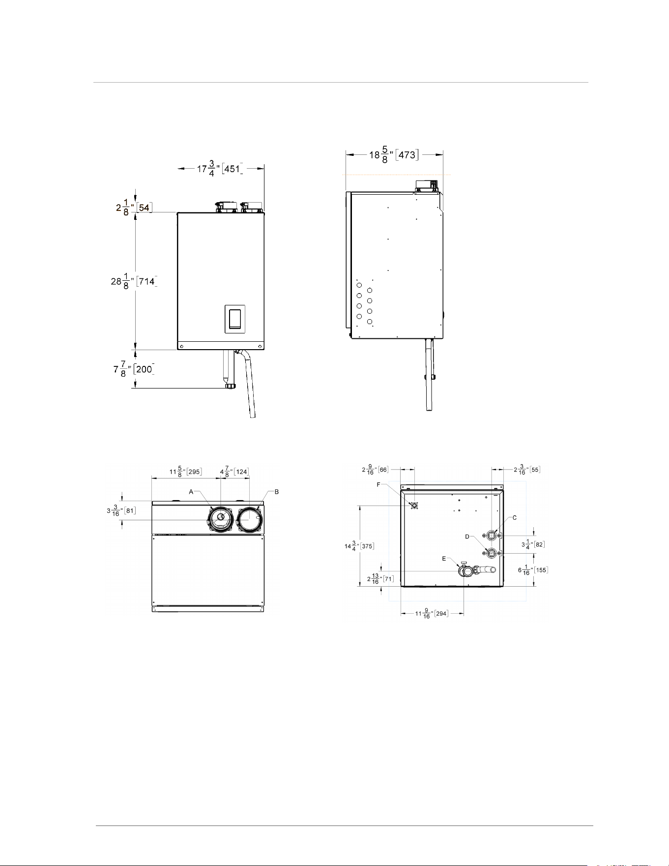
Boiler Model 150 dimensions
Figure 5 Frontal view - Boiler Model 150 Figure 6 Side view - Boiler Model 150
Figure 7 Top view - Boiler Model 150 Figure 8 Bottom view - Boiler Model 150
3
Boiler Model 150 dimensions
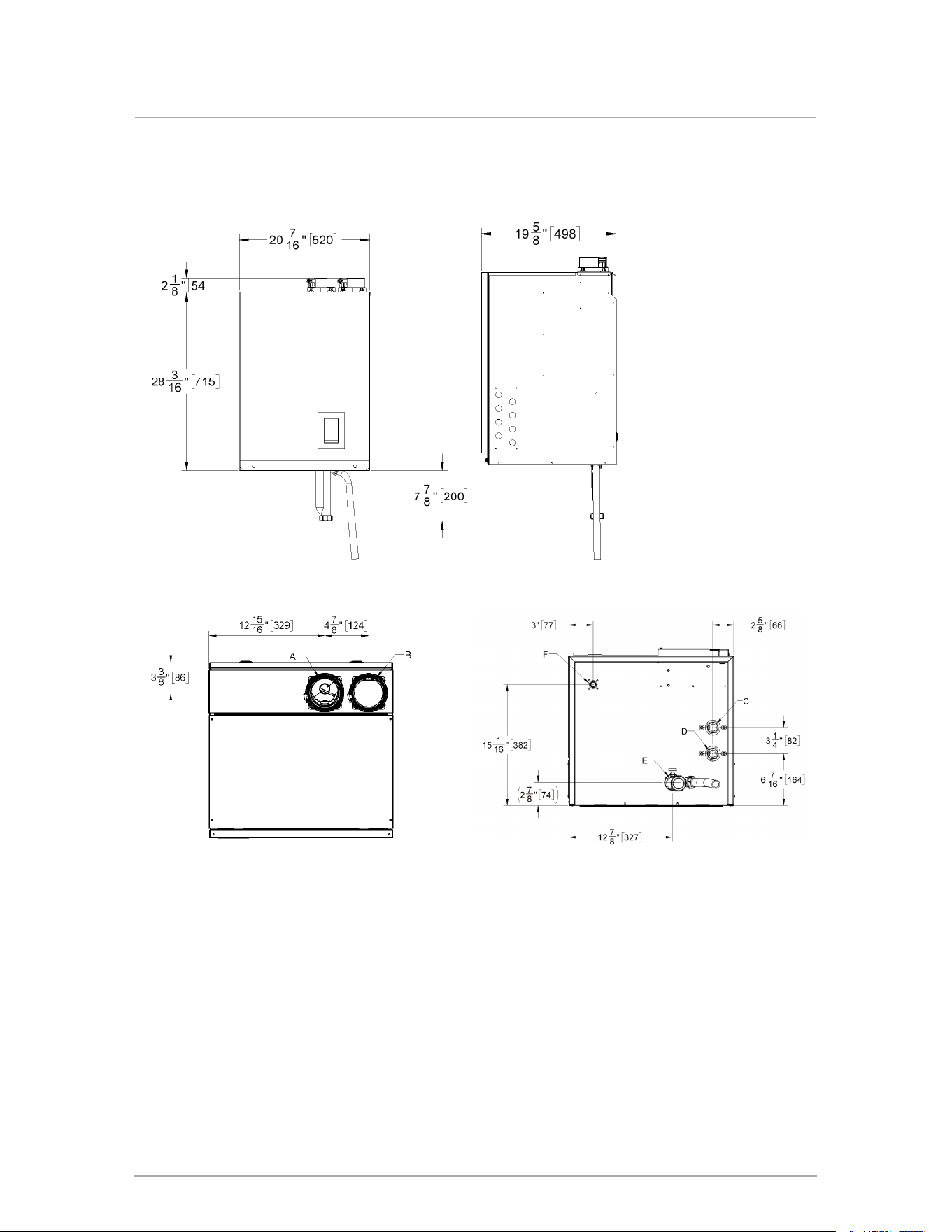
Boiler Model 199 dimensions
Figure 9 Frontal view - Boiler Model 199 Figure 10 Side view - Boiler Model 199
Figure 11 Top view - Boiler Model 199 Figure 12 Bottom view - Boiler Model 199
4
Section: Specifications

Connection specifications
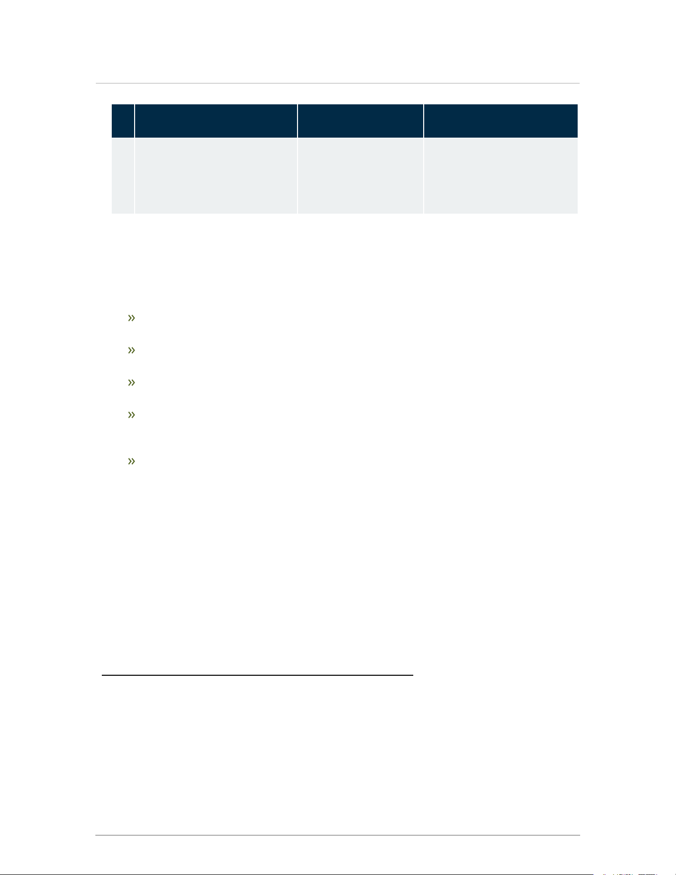
The following table displays the required connection specifications.
Description 110,000 BTU/hr 150,000 BTU/hr 199,000 BTU/hr
A Flue Outlet 3" Schedule 40 or 3" PP (80 mm)
B Combustion Air Inlet 3" Schedule 40 or 3" PP (80 mm)
C Return Water Inlet 1" NPT-M
D Supply Water Outlet 1" NPT-M
E Condensate Outlet ¾" Hose
F Gas Inlet ½" NPT-F
Table 2 Connections
Ignition Stages Timings
Fan Pre-purge 15 seconds
Trial for Ignition 4 seconds
Flame Failure Response <0.8 second
Table 3 Ignition Timings
5
Connection specifications

Intentionally left empty
7
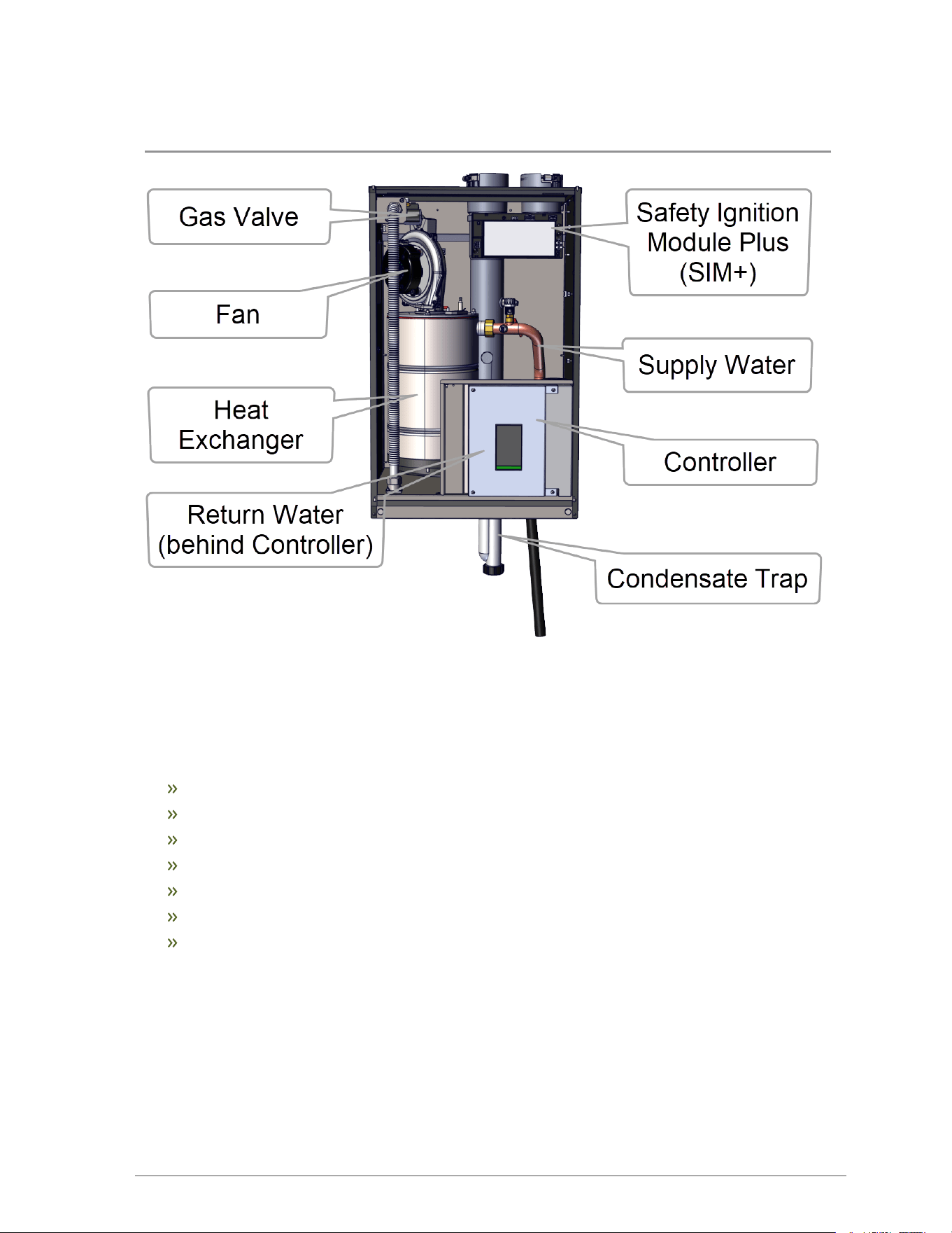
2.0 Introduction
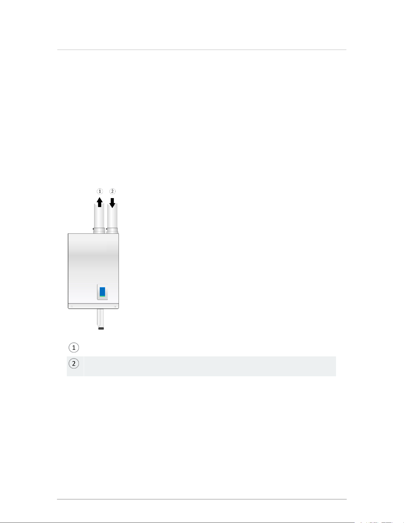
Figure 13 View from the front
2.1 Standard features and benefits
High thermal efficiency
Compact
Turn-down ratio 6.5 to 1
Cascade up to 4 boilers
4 load pump management
1 boiler pump management
Easy-to-use touchscreen

2.2 Warranty
For residential applications, the boiler carries a 5-year warranty on all parts against defects in
materials or workmanship and failures due to thermal shock.
The heat exchanger carries a 15-year limited warranty.
For commercial applications, the boiler carries a 5-year warranty on the heat exchanger and a 2-
year warranty on all parts against defects in materials or workmanship and failures due to
thermal shock.
8
Section: Introduction

9
3.0 Before installation
Caution
Care must be taken to properly size the boiler for its intended use. Prolonged full fire run
time, over-sizing or under-sizing, and incorrect flow rates through the boiler can lead to
increased maintenance costs, equipment stress and premature failure.
Before installing the appliance, it is important to review and observe the following checklist of
precautions:
Precautions Check
Ensure you install the appliance where the combustion air source is not subject to
chemical fouling or agricultural vapors. Exposure to corrosive chemical fumes such as
chlorinated and/or fluorinated hydrocarbons can reduce the life of a boiler. Cleaners,
bleaches, air fresheners, refrigerants, aerosol propellants, dry-cleaning fluids, de-greasers
and paint-removers all contain vapors that can form corrosive acid compounds when
burned in a gas flame. Airborne chlorides such as those released with the use of laundry
detergents are also to be avoided.
□
Locate the appliance where water leakage will not result in damage to the area. If there is
no suitable location, install a suitable drain pan under the boiler. Do not install above
carpeting.
□
At a new construction site, or during renovations, protect the appliance from drywall dust or
other construction-related contaminants. Draw combustion air from a clean source (e.g.,
outdoors) and isolate the boiler from interior dust sources. Do not seal boiler case
openings directly when firing - allow for air circulation and ventilation in the immediate
area.
□
Place the exhaust outlet 12" minimum above the down-turned intake to avoid exhaust re-
ingestion.
□
For sidewall venting options, place the inlet and exhaust terminations on the same side of
the building. The elevation of both pipes can be raised in “periscope style” after passing
through the wall to gain required clearance above grade and snow level.
□
If using the indoor combustion air option, ensure combustion air openings to the boiler
room remain unblocked and free of obstructions.
□
Examine the condensate outlet to ensure proper disposal of condensate will occur during
operation. If condensates are to be discharged into building drain piping materials that are
subject to corrosion, a neutralization package must be used.
□
Ensure that the pressure relief valve is installed with no valves or other means of isolation
between its inlet and the boiler. Make sure the relief valve outlet is piped with unobstructed
piping (minimum ¾" diameter) to a safe discharge location.
□
If the appliance is likely to be exposed to fluid temperatures below 34° F (1° C), a method
of protection to prevent freezing of condensate should be employed. Contact Tech
Support for further information.
□

Precautions Check
When the appliance is in operation, assess the impact of the steam plume typical of a
condensing boiler's exhaust terminal. Generally, intake and exhaust pipes should
terminate at a rooftop or sterile wall location. Boiler condensate is corrosive. Protective
measures must be taken to prevent corrosion damage to metal roofs or other metal
building components in contact with the condensate. Keep exhaust plumes well away from
all building air intakes including those of neighboring properties.
□
10
Section: Before installation

11
4.0 Installation
Refer to the Specifications section for dimensional drawings and connection specifications. Use these
drawings to find a suitable location for the appliance.
4.1 Code requirements
The appliances are tested and certified under CSA 4.9 / ANSI Z21.13 (latest edition). Below are the
code requirements for every installation.
Canada US
Conform to local codes, or in the absence of
these, with the latest editions of CAN/CGA
B149.1 and the Canadian Electrical Code Part 1
CSA C22.2 No. 1.
Where required by jurisdiction, installation must
conform to the Standard for Controls and Safety
Devices for Automatically Fired Boilers,
ANSI/ASME CSD-1.
If there is any conflict, follow the more stringent
regulations.
Conform to the current National Fuel Gas Code
ANSI Z223.1 and the National Electrical Code
ANSI/NFPA 70.
Where required by jurisdiction, installation must
conform to the Standard for Controls and Safety
Devices for Automatically Fired Boilers,
ANSI/ASME CSD-1.
If there is any conflict, follow the more stringent
regulations.
Table 4 Code requirements by country
4.2 Removing an existing boiler
When an existing boiler is removed from a common venting system, the common venting system
may be too large for proper venting of the appliances that remain connected to it. When resizing
any portion of the common venting system, use the minimum size according to the appropriate
tables in the National Fuel Gas Code, ANSI Z223.1- latest edition. In Canada, follow the B149.1
Installation Code.
When removing an existing boiler, the following checks must be carried out for each of the
appliances still connected to the common exhaust system, by operating them one at a time:
Seal any unused opening in the common venting system.
Visually inspect the venting system for proper size and horizontal pitch. Determine that there
is no blockage or restriction, leakage, corrosion and other deficiencies that could cause an
unsafe condition.
(Where practical) Close all building doors and windows such as doors adjacent to
appliances remaining connected to the common venting system and other spaces of the
building.
Turn on clothes dryers and any appliance not connected to the common venting
system.
Turn on any exhaust fans, such as range hoods and bathroom exhausts, so they
will operate at maximum speed. Do not operate a summer exhaust fan.
Close fireplace dampers.
Place in operation the appliance being inspected.
Follow the lighting instructions.
Adjust the thermostat so that the appliance operates continuously.
After determining that each appliance remaining connected to the common venting
system properly vents when tested as outlined above, return doors, windows, exhaust
fans, fireplace dampers and any other gas-burning appliance to their previous condition.
Any improper operation of the common venting system should be corrected, so the
installation conforms with the National Fuel Gas Code, ANSI Z223.1 - latest edition. In
Canada, all installations must conform with the current CAN/CGA - B149.1-10
Installation Code and/or local codes.
4.3 Determining location of the appliance
The boilers are designed and approved for indoor installation (wall or rack mounting) in areas
such as an alcove, basement, or utility room. These areas should have a surrounding
temperature of 32 °F (0°C) to 122 °F (50 °C) and less than 90% relative humidity.
Danger
Do not common vent this appliance with other existing appliances or with a new
appliance.
Warnings
Keep the area around a boiler clear of combustible materials, gasoline, and
other flammable vapors and liquids.
Ensure combustion air is not drawn from areas containing corrosive air such as
swimming pools or spas, including air directly next to outdoor pools and spas.
Ensure that a boiler is not exposed to water leaks from piping or components
located overhead, including condensation from uninsulated cold water lines
overhead.
Protect the gas ignition system components from water (dripping, spraying,
rain, etc.) during appliance operation and when servicing (pump replacement,
condensate trap servicing, control replacement, etc.).
Ensure that combustible materials do not make contact with exposed water
piping and associated components (relief valves, circulators, etc.). Check local
codes for required clearances and/or provide adequate insulation.
12
Section: Installation

4.3.1 Best installation conditions
Below are some factors to consider for best installation conditions:
Install the boiler in areas where the combustion air source is not subject to chemical fouling or
agricultural vapors. Exposure to corrosive chemical fumes such as chlorinated and/or
fluorinated hydrocarbons can reduce the life of a boiler. See list of Known contaminants on
page 4. If boiler is installed in a laundry room, boiler must be direct vented and the intake
cannot terminate near a dryer vent. Similarly, ensure any direct vent air source is not near a
clothes dryer exhaust terminal. Avoid locating the boiler and intake air where they can be
affected by ammonia and/or dust.
Avoid installing a boiler where water leakage will cause damage; for example, above
carpeting. If unavoidable, install a suitable drain pan under the appliance.
Vent location - An important consideration is managing the impact of the steam plume
normally at the exhaust terminal of a condensing boiler. Generally, intake and exhaust pipes
should terminate at a rooftop or sterile wall location to maximize customer satisfaction. Keep
exhaust plumes well away from all building air intakes including those of neighboring
properties. Refer to Sidewall vent termination on page 24.
The minimum clearance requirements for combustible materials (see Table 5 ).
For adequate servicing, we recommend a minimum 24" clearance at the front and 6" above
the boiler. Check local codes for additional access and service clearance requirements.
At a new construction site, or when renovating:
Protect the boiler from drywall dust or other construction related contaminants.
Ensure combustion air is drawn from a clean source (e.g., outdoors).
Isolate the boiler from interior dust sources.
If a dusty environment is temporarily unavoidable, shut off the boiler and service boiler
thoroughly after resuming operation.
13
4.3.1 Best installation conditions
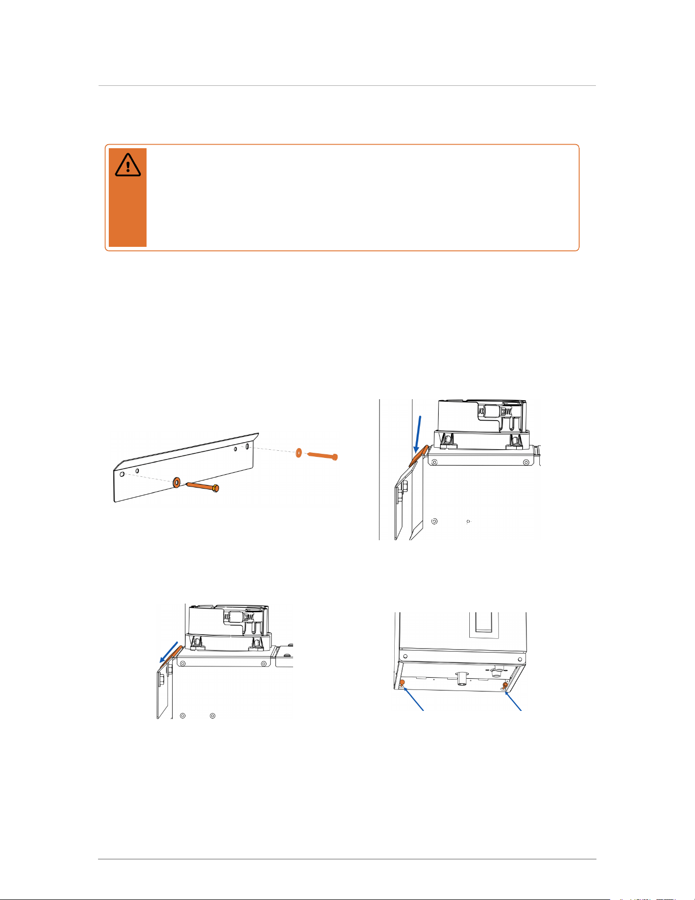
4.4 Mounting the boiler
Warning
Do not mount the appliance to hollow wall structures - The combined weight of
the boiler, its water content and associated piping components can exceed 120
pounds. Fasteners must be rated for this strain, and must be firmly anchored into
solid material that will support this weight. Installers must take necessary precautions
to avoid injury during the installation of this boiler.
You must attach fasteners to solid material capable of supporting the combined weight of the
boiler and piping assembly components. Boiler weight – without water, system piping and
components – is approximately 90 lbs / 40 kg.
1.
Attach the support bracket
(supplied) to the wall studs using
the two ¼" x 2½" long lag screws
with flat washers.
2.
Hook the boiler tab (located on
back of boiler) over the support
bracket flange.
3.
Ensure that the boiler tab is flush
against the mounting bracket
flange.
4.
Secure the lower part of the boiler
to the wall with two field-supplied
¼" bolts.
14
Section: Installation
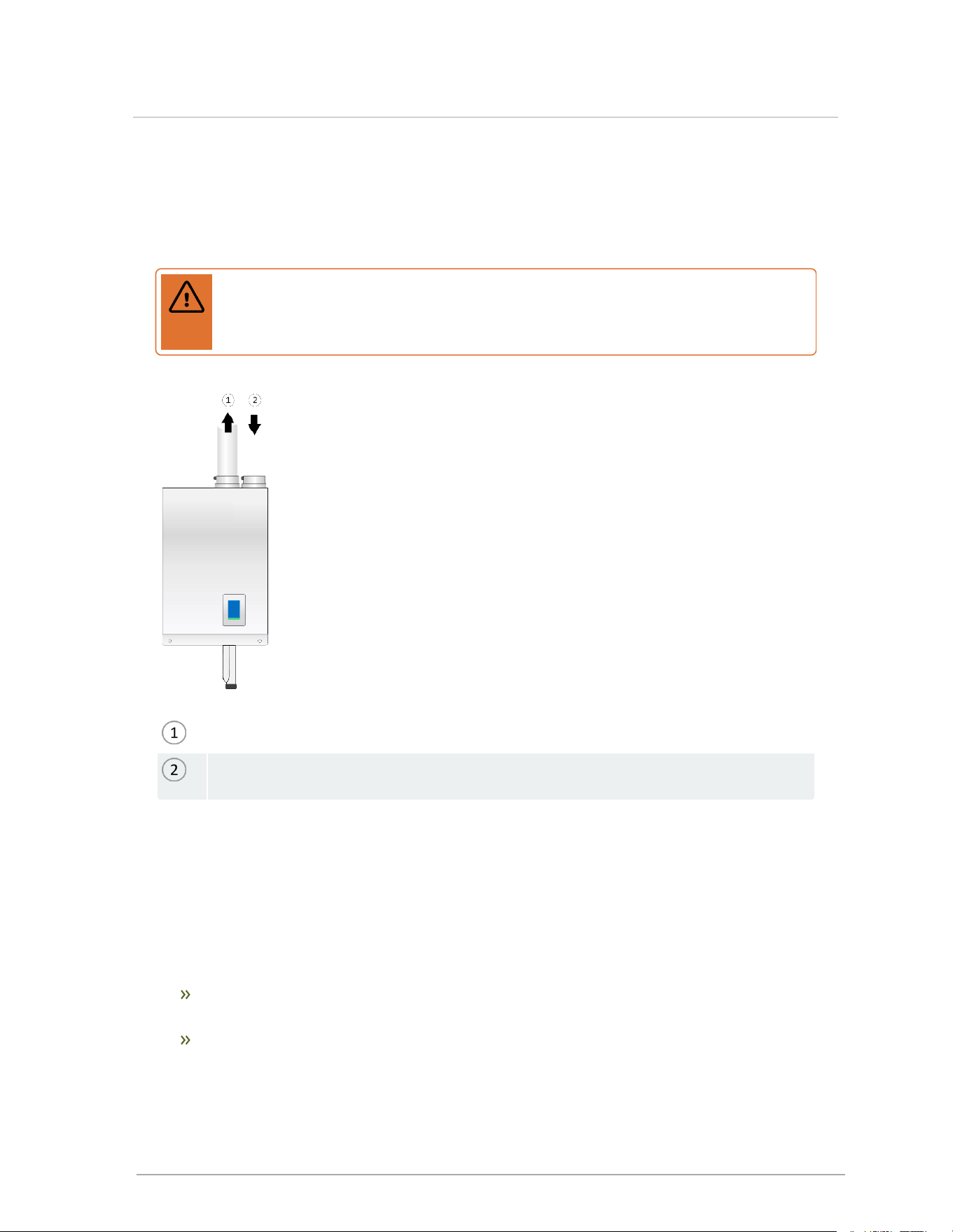
4.5 Connecting the vent and air intake pipes
The appliance offers 3" connections that accept standard 3" PVC/CPVC and polypropylene (PP)
pipe. Use reducing fittings (not bushings)to adapt to smaller diameter pipe. Insert pipe directly into
the 3" female fitting past the gasket, and secure with the built-in clamp (see image below).
Note
Mark the full-insertion depth on the vent pipe.
For PP, no transition adapter is required: the vent connection has a second gasket, approximately
2.5” below the first 3” PVC/CPVC sized gasket, that will seal to standard 80 mm PP pipe. Care
should be taken to ensure that polypropylene pipe is installed so that it extends past this second
gasket. For polypropylene material exposed to outdoor conditions, follow the venting supplier’s
recommendations on UV protection.
Figure 14 Securing a pipe connection
Warning
Ensure that you lubricate the gasket with silicone grease before inserting the venting
material. Fully insert the approved venting material into the boiler's exhaust outlet, and
tighten clamp to ensure the venting connection is locked in place (as shown above).
Combustion air piping - if used - is inserted directly into the 3" connector on the right side. PP pipe
should be inserted firmly into the connector until it cannot go further. The pipe must be secured with
the built-in clamp.
Venting must be supported in accordance with the applicable code and instructions supplied by the
manufacturers.
Warning
Do not mix polypropylene venting materials from different manufacturers. These venting
materials are designed to be installed as part of a complete system. Failure to comply
may result in severe personal injury or death
15
4.5 Connecting the vent and air intake pipes
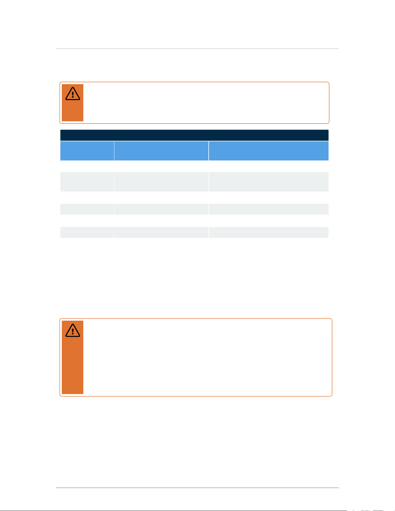
4.6 Installation clearances
Warning
Exposed water piping and associated components (relief valves, circulators, etc.,
should not be in contact with combustible materials. Check local codes for required
clearances and / or provide adequate insulation.
110,000 BTU/hr, 150,000 BTU/hr, 199,000 BTU/hr Clearances
Surface
Minimum distance from
combustible surfaces
Recommended clearance for
installation and service
Front 2" 24"
Rear flue
connection
0" 0"
Left side 0" 4" (allow access to water connections)
Right side 1" 4" (allow access to water connections)
Top 2" 6" (for vent connections)
Bottom 0" (clearance for pipes) 12" (for condensate trap and piping)
Table 5 Clearance distances for boiler mounting sites
A minimum distance below the boiler of 12" is required to provide clearance for the supplied
condensation trap assembly. More clearance will typically be required to accommodate
associated water and gas piping.
4.7 Exhaust venting and air intake
Warning
Venting, condensate drainage, and combustion air systems for the boiler must be
installed in compliance with all applicable codes and with instructions provided in the
respective installation manuals.
Inspect finished vent and air piping thoroughly to ensure all are airtight, and comply
with the instructions provided as well as with the requirements of applicable codes.
Failure to comply will result in severe personal injury or death.
These approved “Category IV” vented appliances offer flexible installations via direct vent (sealed
combustion) or indoor combustion air.
When planning a boiler's installation, consider the appropriate vent materials, travel and
termination.
16
Section: Installation
4.7.1 Venting code
All venting must be installed in accordance with the requirements of the jurisdiction having
authority: in Canada, Part 8, Venting Systems of the B149.1-10 Code and any other local building
codes are to be followed. In the USA, the National Fuel Gas Code, ANSI 223.1, latest edition,
prevails. Where there is a discrepancy between the installation instructions provided, and the
code requirements, apply the more stringent.
4.7.2 Venting options
These appliances are approved with alternative venting options: either 2-pipe direct vent or vent
pipe with indoor air. With direct vent, combustion air is piped directly to the boiler’s air intake from
outdoors. Using the indoor air alternative, air for combustion is drawn from the indoor air
surrounding the boiler.
Provided the maximum overall vent length limit is not exceeded, the boiler may be vented through
the wall, directly through the roof, or upward using an existing, but otherwise unused, chimney as
a vent raceway.
4.7.3 Exhaust vent material
Warning
Covering non-metallic vent pipe and fittings with thermal insulation is prohibited.
Exhaust vent material – Canada
Use PVC, CPVC, Polypropylene (PP), or Stainless Steel (SS) vent component systems approved
under ULC-S636 Standard for Type BH Gas Venting Systems, or stainless steel Type BH venting
systems. ULC-S636 components are certified as systems including pipe, fittings and
cement/primer for PVC/CPVC and must be installed in strict accordance with manufacturers
instructions. The vent temperature is limited by the boiler controller with the use of a flue
temperature sensor to ensure the maximum temperature of the PVC venting material is not
exceeded.
Exhaust vent material – U.S.A
PVC, CPVC, PP, or SS venting materials are approved for use with these boilers in most of the
USA. Check local codes to determine if any materials are prohibited. The vent temperature is
limited with the use of the flue temperature sensor and software to ensure that the maximum
temperature of the PVC venting material is not exceeded. PVC venting material shall be certified
to Sch. 40 ASTM D1785 or D2665. CPVC material shall be certified to Sch. 40/ASTM F441.
17
4.7.1 Venting code
Exhaust vent material - general
Use of cellular core PVC (ASTMF891), cellular core CPVC, ABS or Radel®
(polyphenolsulfone) in venting systems is prohibited. Do not use ABS or any cellular core pipe
for exhaust venting.
4.7.4 Direct vent
Direct vent is a two-pipe system that draws combustion air (air intake) from outdoors, and
discharges exhaust gases to the outdoors. Ensure that adequate separation is maintained
between the air intake inlet and the exhaust vent terminal. Refer to the vent terminal
configuration drawings in the "Vent Termination" sections.
Flue gas exhaust to outdoors
Combustion air from outdoors. "Direct Vent" installation: check air intake outside is
clear of obstructions.
Figure 15 Direct vent
Air intake installation
At a new construction site, or during renovations, action must be taken to protect the boiler
from drywall dust or other construction related contaminants; combustion air should be drawn
from a clean source (e.g. outdoors) and the boiler should be isolated from interior dust
sources. Do not seal boiler case openings directly when firing (See Known contaminants on
page 4).
18
Section: Installation
Warnings
The boiler door must be in place during operation (except for maintenance and
service).
In addition to preventing ingestion of chemical contaminants, ensure air intake
terminals are not installed in locations where contamination might occur due to
ingestion of particulate foreign material (dust, dirt and debris).
Configure intake air openings, so that rain or other forms of moisture cannot
enter the air intake piping system. Otherwise serious damage to the boiler may
result.
Notes
When installing air intake piping, ensure that a "trap" is not formed in the piping
causing a build-up of water and blockage of intake air. Such blockages will
cause a boiler safety shut-down.
Filters require checking and cleaning or replacing on a regular schedule based
on the severity of the problem.
Exhaust venting installation
Horizontal sections of PVC/CPVC exhaust venting must slope down to towards the boilers
maintaining a minimum of 1/4" per foot slope so condensate runs back to the boiler.
Polypropylene exhaust venting requires 5/8" per foot minimum.
Exhaust piping is inserted directly into the left connector on the top of the boiler, then runs
horizontally or vertically to the outdoors. Screen material can be placed at the outlet as
appropriate for the environment (e.g., insects, dust).
Check that material meets local codes including fire stopping requirements. Some local
jurisdictions require a minimum initial length of pipe be exposed or accessible for
inspection. Pipe clearances - no manufacturers' requirements; follow local codes. All piping
must be liquid and pressure tight.
Ensure all venting components are clear of burrs/debris prior to assembly. Clear plastic
debris left in the combustion air piping to avoid intake into the fan.
For PVC, CPVC and ABS (Intake only) secure joints using (CPVC cement approved under
ULC-S636, in accordance with its manufacturer instructions; PVC (ASTM D2564), or
PVC/ABS (D2235) - Use transition glue anywhere that PVC and CPVC are joined. Follow
the cement manufacturer’s instructions closely when joining various components. For
polypropylene, connections must be secured using approved clips or clamps (follow vent
manufacturers installation instructions).
Ensure that vent connections are liquid and pressure tight. Prior to firing the boiler, and
before any of the venting run is concealed, run the fan in high fire via the test operation
menu on the boiler display. Then coat all joints with an approved leak test solution just as
you would joints in a gas line and inspect to see if bubbles form, indicating that there is a
leak. The installer must fill the condensate trap prior to testing.
19
4.7.4 Direct vent
Re: venting passage through ceiling and floor:
Confirm material meets local codes including fire stopping requirements.
Check the local jurisdiction on the minimum initial length of pipe that should be
exposed or accessible for inspection.
Follow the local codes for pipe clearances - no manufacturers requirements.
Ensure that piping is liquid and pressure tight.
Air intake and exhaust vent length allowance
Warning
Follow all installation instructions supplied by the piping and fitting manufacturer.
The maximum vent lengths shown are separate for the intake and exhaust. For example, for a
maximum vent length of 100 ft, the exhaust can travel a maximum of 100 equivalent ft and the
intake can travel a maximum of 100 equivalent ft. Any unused vent lengths used on one side
can not be added to the other. Equivalent feet of any elbows, termination kits, or flexible pipe
must be subtracted from the maximum length using the following table:
Intake/Exhaust 110,000 BTU/hr 150,000 BTU/hr 199,000 BTU/hr
2-inch rigid pipe 100 ft (max.) 50 ft (max.) Not permitted
3-inch rigid pipe 240 ft (max.) 170 ft (max.) 100 ft (max.)
90° elbow Each 90° elbow is equivalent to 8 feet
90° long sweep
elbow
Each 90° elbow is equivalent to 5 feet
45° elbow Each 45° elbow is equivalent to 3 feet
PPs 87-90° elbow Each 87-90° elbow is equivalent to 8 feet
(Intake only)Air
Intake Filter (P-357)
Equivalent to 8 ft
2-inch Stainless
Sidewall Terminal
exhaust vent (P-256)
Exhaust:equivalent
to 20 feet
Not permitted
Intake: equivalent to
0 (zero)feet
3-inch Stainless
Sidewall Terminal -
(P-257)
Exhaust: equivalent to 20 feet
Intake: equivalent to 0 (zero)feet
Flexible PP 3-inch
Flexible pipe
maximums
Limited to 45 feet Limited to 45 feet Limited to 30 feet
20
Section: Installation
Intake/Exhaust 110,000 BTU/hr 150,000 BTU/hr 199,000 BTU/hr
Flexible PP 3-inch
Flexible pipe
equivalents
Allow 1.2 x actual
length (e.g., 10 feet of
3-inch flexible pipe =
12 feet of rigid pipe)
Allow 2 x actual
length (e.g., 10 feet
of 3-inch flexible
pipe = 20 feet of
rigid pipe)
Allow 3.3 x actual
length (e.g., 10 feet
of 3-inch flexible
pipe = 33 feet of
rigid pipe)
Table 6 Maximum air intake pipe and maximum exhaust vent length
Notes
Unused intake travel cannot be added to the exhaust. Unequal intake and exhaust
piping is allowed.
Support should be provided for intake and vent piping, particularly for horizontal runs
(follow local code).
Example of equivalent length calculations for a Boiler Model 110:
A Boiler Model 110 can be situated up to 100 feet (actual vent length allowance)from the
vent termination using 2-inch pipe, or up to 240 feet using 3-inch pipe.
For 6 x 90º elbows, equivalent vent length is 6 x 8 ft = 48 ft; in this case the maximum lineal
(straight) length of pipe allowed using 2-inch pipe is 52 feet (100’ – 48' = 52'). The same
boiler using 3-inch pipe can have up to 192 feet (240' – 48' = 192').
For 3-inch flexible PPS pipe, up to 45 linear feet is allowed in vertical orientation (> 45 °).
The equivalent length of 3-inch flexible PP pipe should be calculated using a multiple of
1.2 (e.g., 45 'x 1.2 = 54').
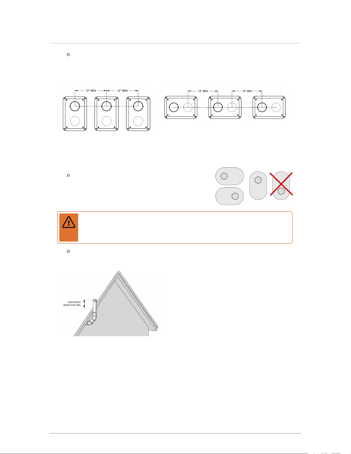
4.7.5 Rooftop vent termination
Warning
Condensate can cause corrosion of metal roofing components and other roofing
materials. pH levels can be as low as 3.0. Check with the builder or roofing contractor
to ensure that materials are resistant to acidic condensate.
a. Rooftop vents must terminate as follows:
Do not exhaust vent into a common venting system.
The exhaust pipe can terminate in an open vertical orientation without concern
about rain infiltration; rain will drain away through the condensate trap.
Optional bird screen may be placed in a termination fitting. Leave unglued, and hold
in place with a short nipple. This permits easy access for cleaning.
21
4.7.5 Rooftop vent termination
b. For rooftop direct vent systems:
Rooftop, two-pipe, direct vent configurations, including typical clearance
requirements are shown below in the following images.
Figure 16 Rooftop vent terminal
configurations
Figure 17 Rooftop vent termination
with sidewall combustion air
Vent screen retainer
Exhaust
Vent screen
22
Section: Installation
Inlet
Flashing
Figure 18 Rooftop vent terminal vent screen and retainer
The intake air pipe is not typically drained, so it must be terminated with a down-
turned elbow as shown.
The intake pipe does not need to penetrate the roof at the same elevation as the
exhaust (as shown); lower down on the roof is acceptable.
Best Practice: To reduce the possibility of expansion noise, allow a ¼" gap
around the exhaust and air intake piping.
For roof top venting of multiple boiler sets, group all intake terminals together for a
common penetration through a custom cap. Alternatively, place close together
using commonly available pipe flashing. Similarly, group the exhaust pipes and
place the two separate groups of pipes at least 3' apart (the closest intake and
exhaust pipes must be 36", or more, apart). Use the same 12" (minimum) vertical
separation for all termination options. For alternate group terminations, contact
Tech Support for written guidance.
Roof top concentric termination kits are approved for use with this boiler model.
Installation of the vertical roof top termination must follow the installation
instructions supplied with the venting material manufacturer. Care must be taken to
install the termination kit a minimum horizontal distance of 10' (305 cm) away from
any portion of the building and a minimum of 1 foot (30 cm) above the roof line plus
the anticipated snow line.
Caution
Take care installing termination kits when the outdoor temperature drops below 5°F/-
15°C. Possible blockage of the combustion air intake can occur when the outdoor
temperature drops below this temperature.
23
4.7.5 Rooftop vent termination
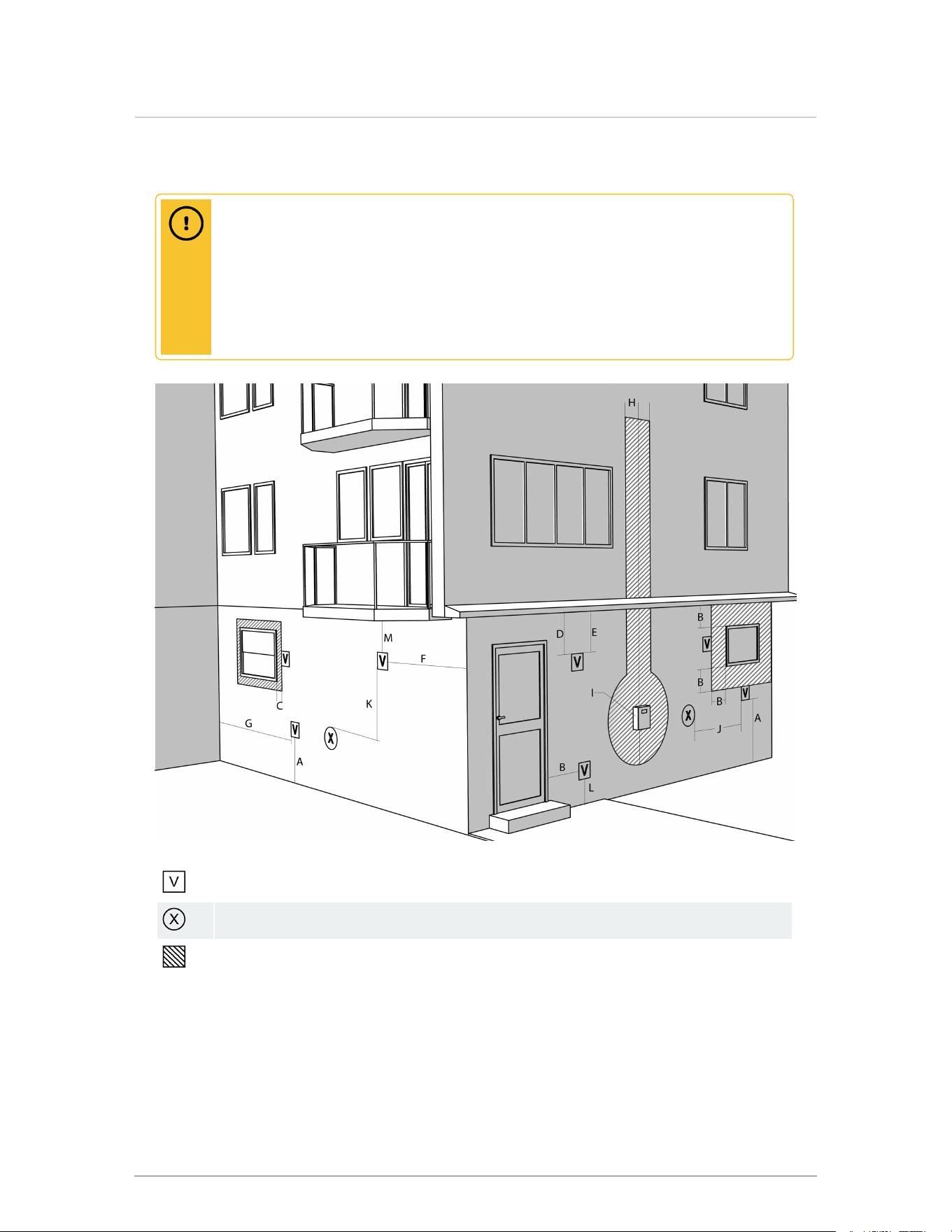
4.7.6 Sidewall vent termination
Caution
Vent termination clearances in this section are code minimum and may be
inadequate for your installation. Building envelope details must be examined
carefully. Take action to avoid moisture entering building structures. Serious
structural damage may occur if adequate precautions and clearances are not
considered. These precautions apply to neighboring structures as well as to the
structure the boiler(s) are installed in.
Vent terminal
Air supply inlet
Area where terminal is not permitted
Figure 19 Minimum clearances from vent/air inlet terminations
24
Section: Installation

Description
Canadian
Installations
1,2
12
US Installations
2,3
3
A Clearance above grade,
veranda, porch, deck, or
balcony
12 in (30 cm) 12 in (30 cm)
B Clearance to window or door
that may be opened
36 in (91 cm) for
appliances >100,000
Btuh (30 kW)
12 in (30 cm) for appliances >
50,000 Btuh (15 kW)
C Clearance to permanently
closed window
*
*
D Vertical clearance to ventilated
soffit located above the terminal
within a horizontal distance of
2ft (61 cm) from the center line
of the terminal
* *
E Clearance to unventilated soffit * *
F Clearance to outside corner * *
G Clearance to inside corner 4 ft (122 cm) 4 ft (122 cm)
H Clearance to each side of center
line extended above
meter/regulator assembly
3 ft (91 cm) within a
height 15 ft above the
meter/ regulator
assembly
*
I Clearance to service regulator
vent outlet
Above a regulator within
3 ft (91 cm) horizontally
of the vertical center line
of the regulator vent
outlet to a maximum
vertical distance of 15 ft
(4.5 m)
*
J Clearance to non-mechanical
air supply inlet to building or the
combustion air inlet to any other
appliance
36 in (91 cm) for
appliances >100,000
Btuh (30 kW)
12 in (30 cm) for appliances >
50,000 Btuh (15 kW)
K Clearance to mechanical air
supply inlet
6 ft (1.83 m)
3 ft (91 cm) above if within 10 ft
(3 m) horizontally
1
In accordance with the current CAN/CSA-B149 Installation Codes.
2
If locally adopted installation codes specify clearances different than those illustrated, then the most stringent shall apply.
3
In accordance with the current ANSI Z223.1 / NFPA 54 National Fuel Gas Code.
*
Clearances in accordance with local installation codes and the requirements of the gas supplier. The minimum distance from adjacent public
walkways, adjacent buildings, openable windows, and building openings shall not be less than those values specified in the National Fuel Gas
Code, ANSI Z223.1/NFPA 54, and/or the Natural Gas and Propane Installation Code, CSA 8149.1.
25
4.7.6 Sidewall vent termination
Description
Canadian
Installations
1,2
12
US Installations
2,3
3
L Clearance above paved
sidewalk or paved driveway
7 ft (2.13 m)
4
Vents cannot be located
above public walkways or
other areas where condensate
or vapor can cause a nuisance
or hazard.
M Clearance under veranda,
porch, deck or balcony
12 in (30 cm)
5
*
Table 7 Vent/air inlet termination clearances
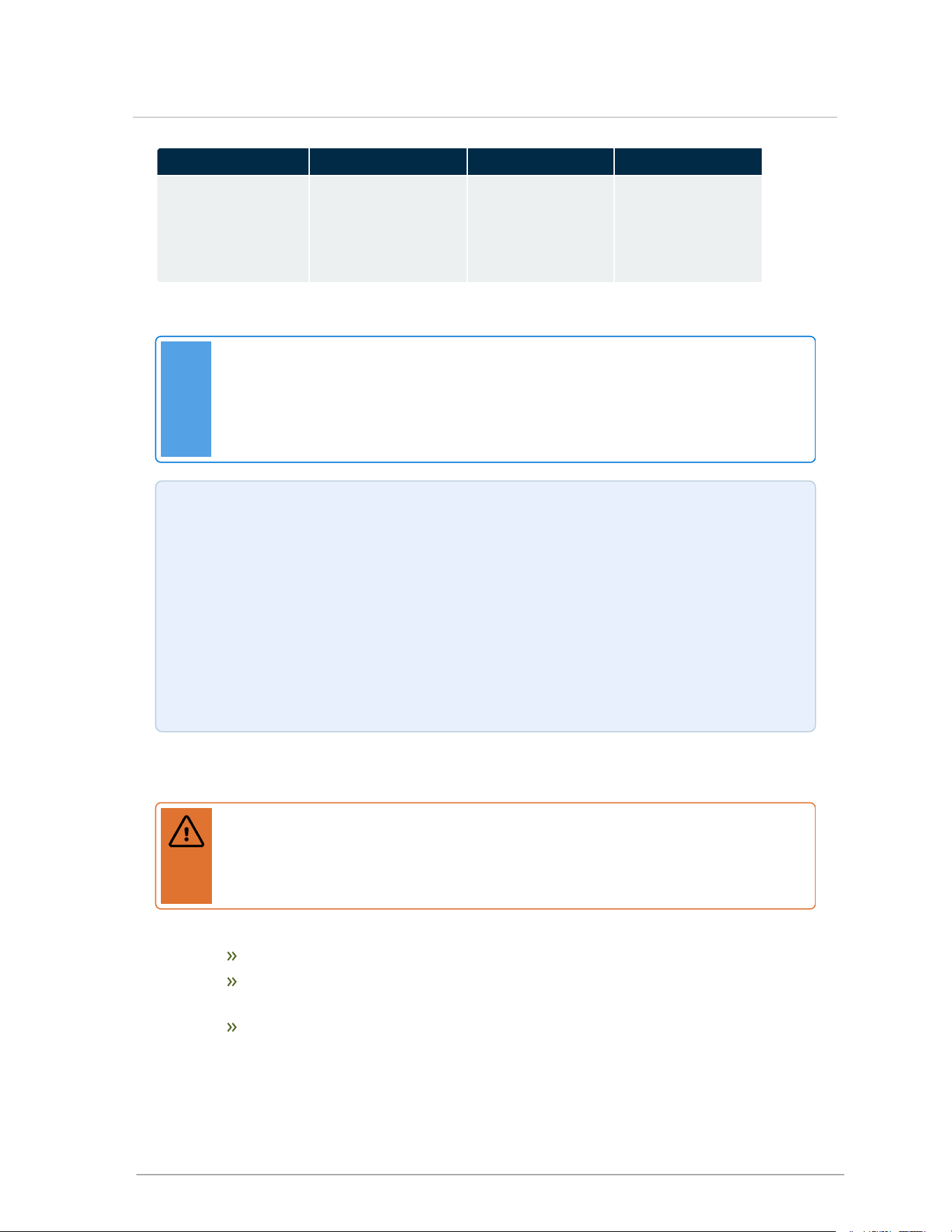
Sidewall direct vent with separate vent and air pipes must be terminated as follows:
Locate the intake air and exhaust vent terminations on the same plane (side) of the
building.
Place the exhaust vent termination so that it reaches minimum 12" above the down-
turned intake to avoid exhaust re-ingestion.
(Optionally) Raise the elevation of exhaust termination “periscope style” after passing
through the wall, to gain the required clearance as shown in Figure 20 and Figure 21 .
Use a 45° elbow on the exhaust termination to launch the plume up and off the sidewall
(for protection of wall). A short piece of venting cut at 45° gives a horizontal termination
protected from wind loads (see Figure 21 , and Figure 23 ).
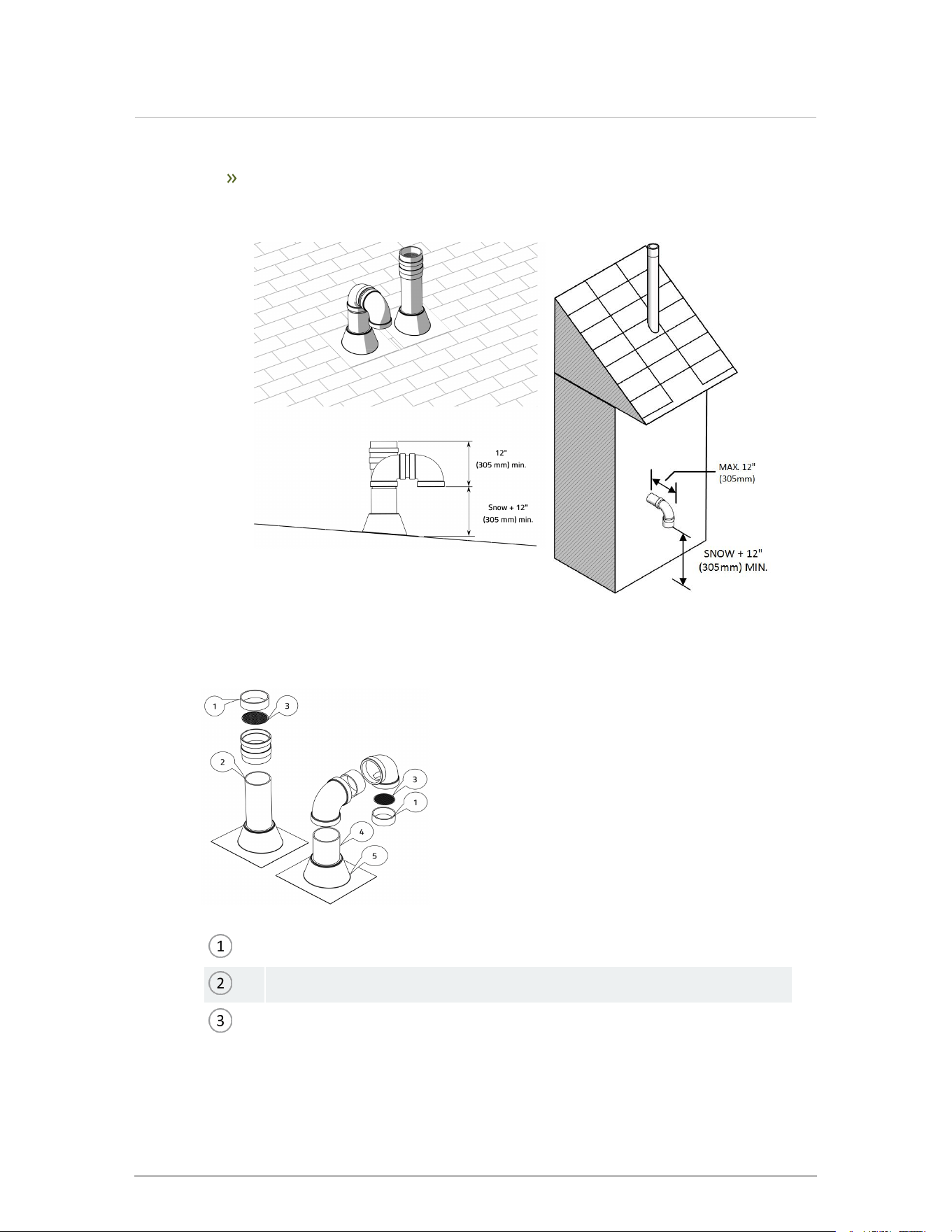
Recommended: the use of a bird screen of ¼" stainless steel or plastic mesh (IPEX
System 636 drain grate) to guard against foreign objects.
1
In accordance with the current CAN/CSA-B149 Installation Codes.
2
If locally adopted installation codes specify clearances different than those illustrated, then the most stringent shall apply.
3
In accordance with the current ANSI Z223.1 / NFPA 54 National Fuel Gas Code.
4
A vent shall not terminate directly above a sidewalk or paved driveway that is located between two single family dwellings and serves both
dwellings.
5
Permitted only if veranda, porch, deck, or balcony is fully open on a minimum of two sides beneath the floor.
*
Clearances in accordance with local installation codes and the requirements of the gas supplier. The minimum distance from adjacent
public walkways, adjacent buildings, openable windows, and building openings shall not be less than those values specified in the National
Fuel Gas Code, ANSI Z223.1/NFPA 54, and/or the Natural Gas and Propane Installation Code, CSA 8149.1.
26
Section: Installation
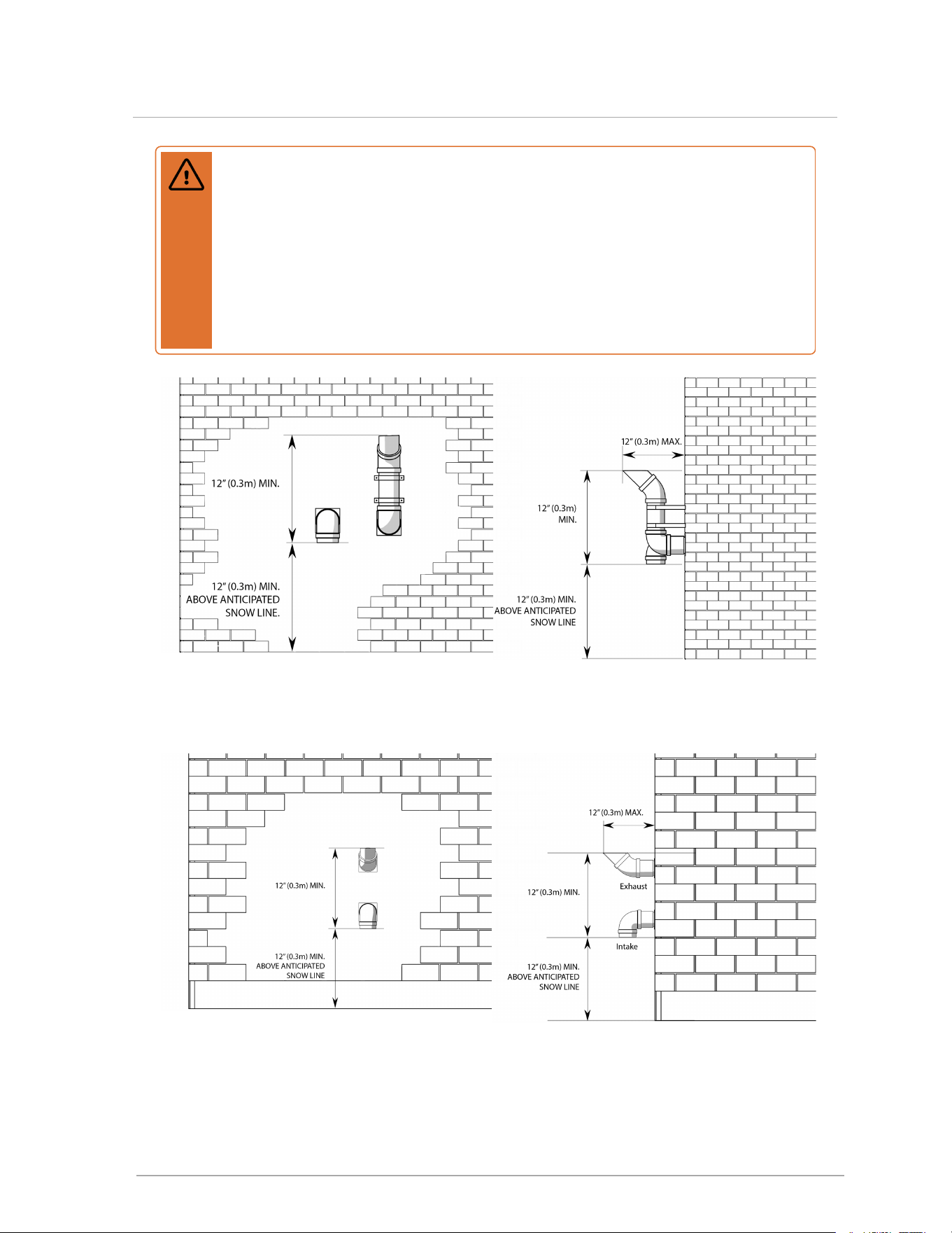
Warning
Important!: Maintain at least the minimum separation of exhaust vent termination from
boiler intake air as illustrated in Figure 20 , Figure 21 , Figure 22 and Figure 23 .
Failure to do maintain the minimum separation can result in a dangerous situation
where exhaust gasses are re-ingested with combustion air. Damage to the boiler can
result from a failure to maintain these separations. Third party vent termination kits and
concentric wall penetration kits that do not maintain these minimum separations must
not be used. Improper installation will void the warranty.
Figure 20 Vent termination clearance--horizontal
perforations
Figure 21 Vent termination clearances--horizontal
perforations, side view
Figure 22 Vent termination clearance--vertical
alignment
Figure 23 Vent termination clearances--vertical
alignment, side view
27
4.7.6 Sidewall vent termination
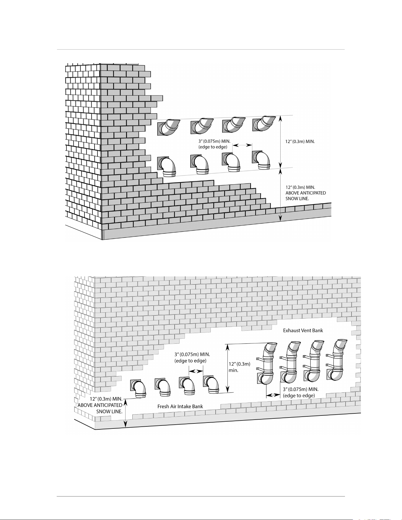
Figure 24 Sidewall vent termination configuration option 1
Figure 25 Sidewall vent termination configuration option 2
28
Section: Installation
Sidewall direct vent with stainless sidewall terminal must be terminated as follows:
The 3-inch Stainless Sidewall Terminal (SST) P-257 kit is approved for use with boiler
models 110, 150, and 199 when the equivalent length calculation (for exhaust) in the table
Air intake and exhaust vent length allowance on page 20 is used. The 2-inch P-256 is
approved for the Boiler Model 110 only.
Install the SST to comply with the minimum vent clearances listed in Table 7 .
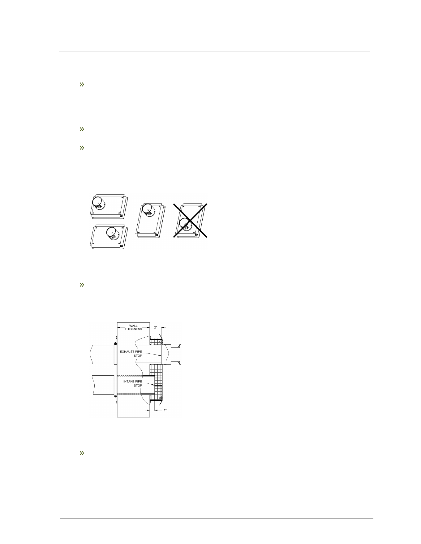
Install the SST with the vent and intake pipes horizontally beside each other or vertically
with the vent pipe on top. The vent pipe cannot be installed below the intake. The vent cap
must be installed with the openings directed up and down (see Figure 26), and not side to
side.
Figure 26 Allowed SST installation orientations
The SST vent/air connections fit Sched. 40 PVC/CPVC pipe. PP pipe cannot be used with
the SST. The pipes must extend completely through the wall as shown below. The SST is
an external fixture, and is not part of the sealed vent system that runs inside the building.
Figure 27 Pipes extend completely through the wall (Vertical orientation shown)
Ensure that the vent termination location does not exceed the allowed maximum
equivalent vent length, including the allowance for the SST.
29
4.7.6 Sidewall vent termination
Install multiple vent SST installations level with one another and maintain at least the
minimum separation distances shown below. The terminals shall not be stacked
vertically.
Figure 28 : Minimum separation for multiple
vent installation - vertical orientation
Figure 29 : Minimum separations for multiple vent
installation - horizontal orientation
Approved PVC Side Wall Termination kits are listed below:
Ipex # 196985 3"
Figure 30 Approved PVC Side Wall Termination configuration
Warning
In areas of high snowfall, users must be advised to check side wall vent and air
intake terminations on a regular basis to ensure blockage does not occur.
Where an exhaust passes through a sidewall too close to a soffit, the venting must
extend past the soffit by transitioning to vertical as shown below.
Figure 31 Sidewall vent termination transition to vertical to clear soffit
30
Section: Installation
4.7.7 Indoor air combustion air intake
An “Indoor Combustion Air installation” can be described as air for combustion that is taken from
the air surrounding the boiler.
Warning
When using indoor air options, supply adequate combustion air to the boiler room
according to the requirements of all applicable codes.
Flue gas exhaust to outdoors
Combustion air from boiler room. For indoor air installation, check air intake and boiler
room combustion air opening(s) to ensure they are clear of obstructions.
Figure 32 Indoor combustion air intake
To support combustion, an ample air supply is required. This may require direct openings in the
boiler room to the outside. If the boiler is not in a room adjacent to an outside wall, air may be
ducted from outside wall openings.
Provisions for combustion and ventilation air must be made as follows:
in the USA, in accordance with the National Fuel Gas Code, ANSI Z223.1 (latest edition),
or applicable provisions of the local building codes
in Canada, in compliance with B149.1 (latest edition).
31
4.7.7 Indoor air combustion air intake
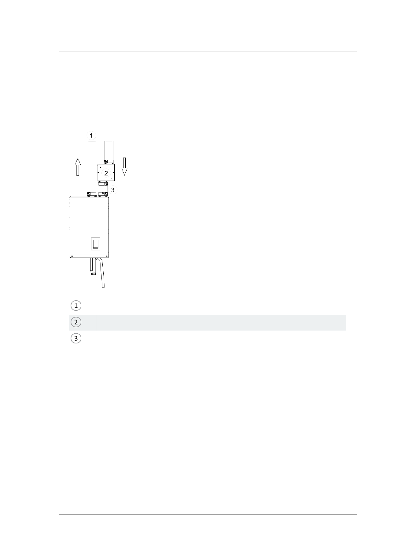
4.7.8 Combustion air filtration system
If combustion air contamination from ingested particulate matter is a concern in any
installation, an optional air intake filter may be installed. The P-357 kit air intake filter has a low
pressure drop and is equivalent to straight venting in the boiler's intake air venting.
Flue gas exhaust to outdoors
Air intake filter
3-inch schedule 40 pipe
Figure 33 Direct vent - intake, exhaust system with optional air intake filter (filtration may also be used
on indoor air applications as required)
32
Section: Installation
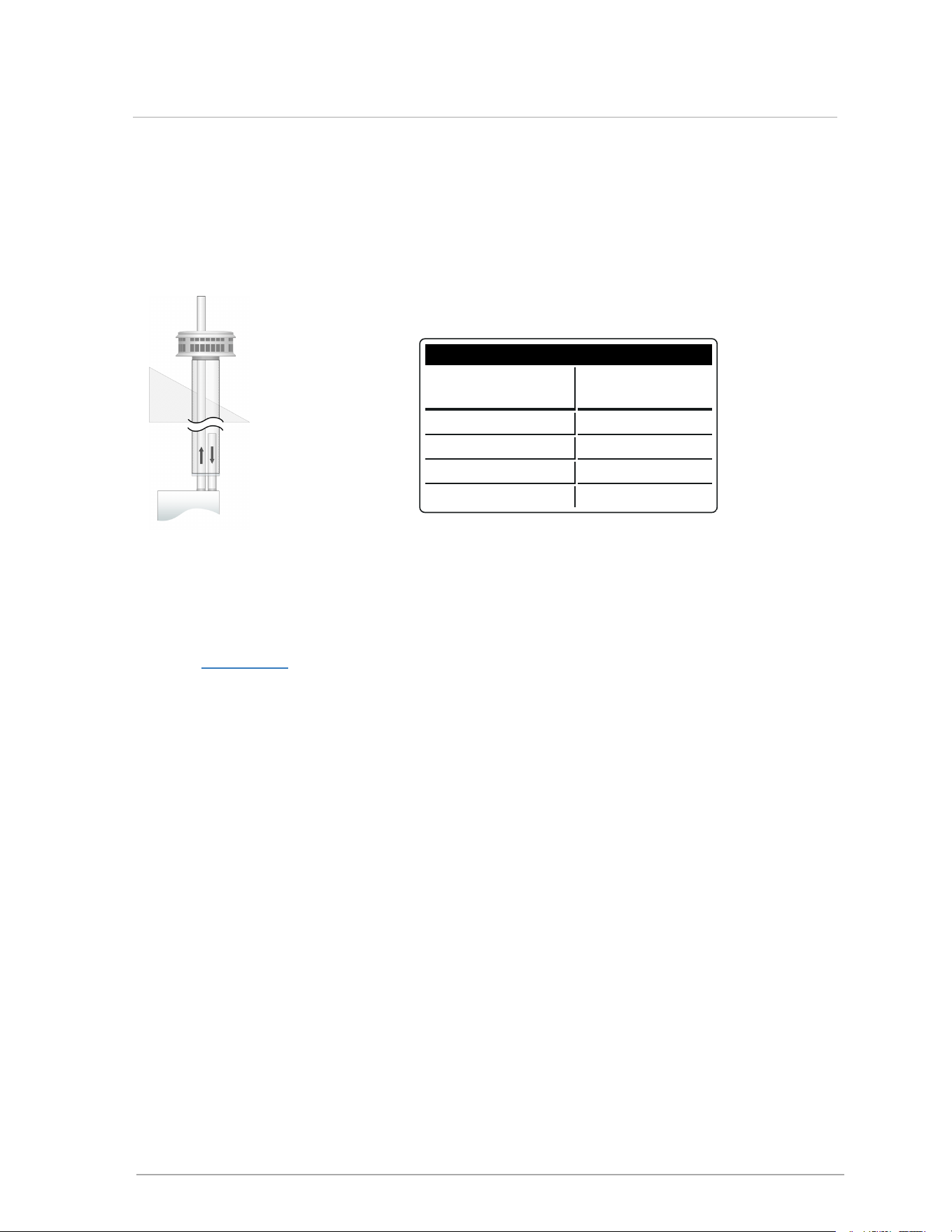
4.7.9 Using an existing vent as a chase
Existing, de-commissioned venting can serve as a chase to greatly simplify the venting of a retrofit
boiler. B-vent from a replaced atmospheric boiler can be used as a chase for a boiler's exhaust
venting and also a source for its intake air, as illustrated, if the chase vent meets the minimum size
shown below.
Figure 34 Using an existing vent as a
chase for exhaust venting and intake air
supply
R
Exhaust chase / intake air vent size
Boiler vent
requirement
Chase vent
minimum
2 " 4"
3" 6"
4" 7"
6" 10"
Table 8 Minimum vent sizes for exhaust chase and intake
air
Refer to Rheem.com for a Technical Note on details that must be observed. Information is also given
on using existing vent as a chase to vent multiple boilers.
4.8 Closet installations
For installations in a confined space (such as a closet), ventilation openings may be needed through
a door or wall to prevent excessive heat from building up inside the space.
The appliance must not be exposed to surrounding air above 122°F (50°C) or below 32°F (0°C).
33
4.7.9 Using an existing vent as a chase
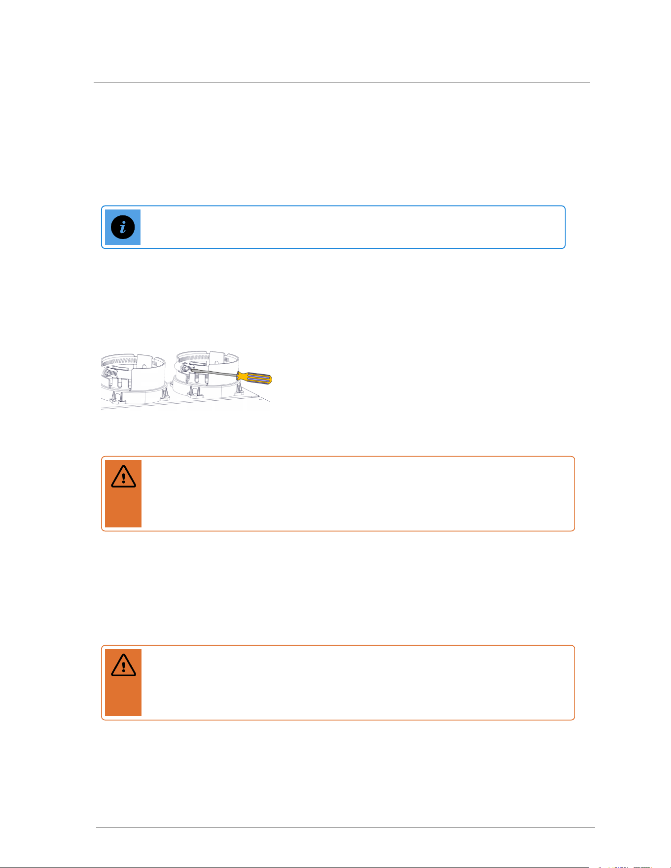
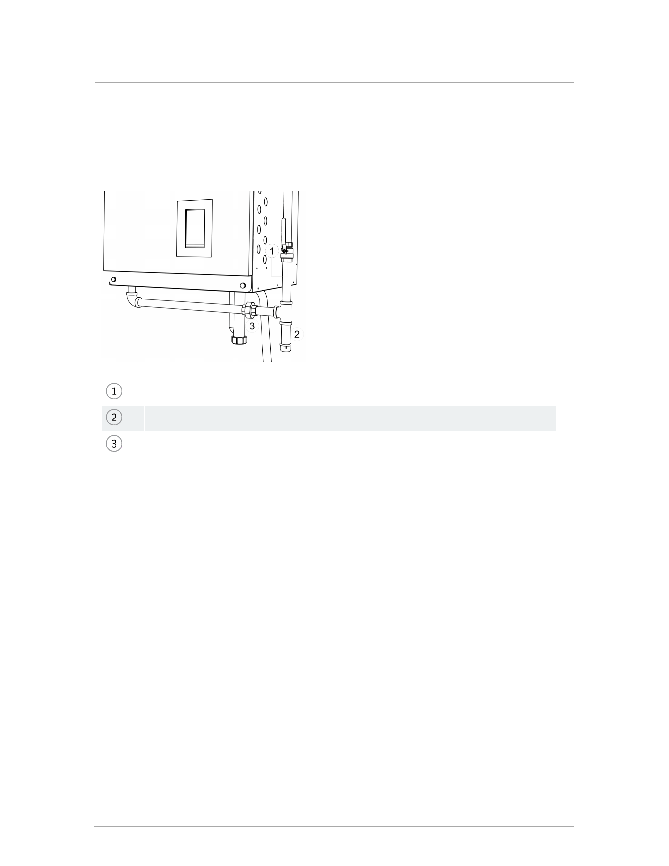
4.9 Installing a condensate trap
The vent configuration promotes the safe drainage of moisture from the boiler and exhaust
venting without flowing liquids back through the heat exchanger (as done by some other
condensing boilers).
Warning
Fill the trap with water before initially firing the boiler to prevent exhaust fumes from
entering the room. Never operate the boiler unless the trap is filled with water. Failure
to comply will result in severe personal injury or death.
Ensure the supplied trap is correctly installed and filled with water.
When required, add (and maintain in good condition) a neutralization tank. For information
on installing a condensate neutralizer, see Installing a condensate neutralizer on page 35.
The condensate trap must be installed on the drain connection at the base of the boiler.
The condensate drain must be piped to within 1" of a drain or connected to a condensate
pump. The drainage line must slope down to the drain at a pitch of ¼" per foot so
condensate runs towards the drain.
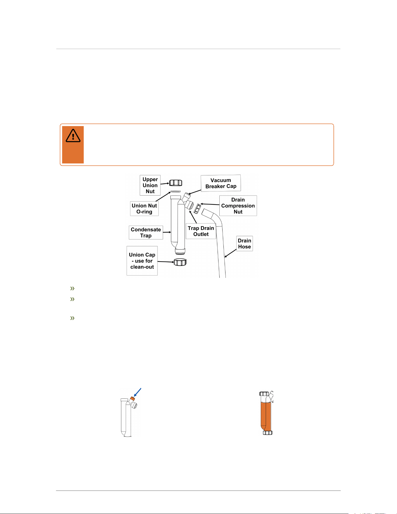
1.
Place the vacuum breaker cap over
the vacuum breaker opening and
push firmly.
2.
Fill the condensate trap with
water.
34
Section: Installation
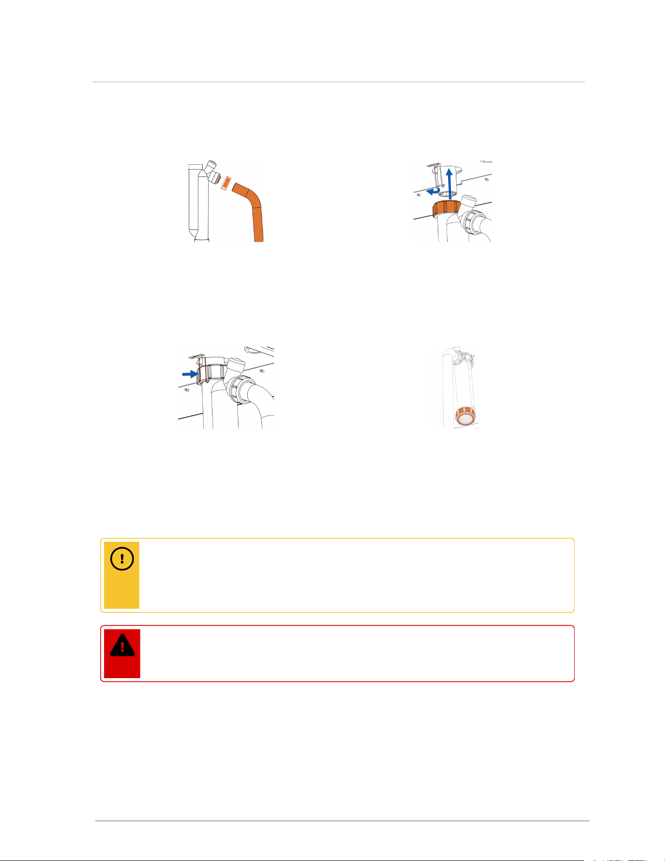
3.
Attach the drain hose and tighten
the drain compression nut
(including washer).
4.
Slide the trap over the boiler drain
outlet, and tighten upper union
nut.
5.
Ensure that the trap upper union nut
is secured by the outlet clip.
6.
Check that all trap fittings have
been hand-tightened to prevent
leakage of flue gases. Do not use
tools and over-torque. Check for
leaks.
4.10 Installing a condensate neutralizer
If discharging condensate into building drain piping materials that are subject to corrosion, use a
neutralization package.
Caution
After installing a condensate neutralization package, the pH of the condensate discharge
must be measured on a regular schedule to ensure the neutralizing agent is active and
effective.
Danger
The water in the condensate neutralizer can cause severe burns to the skin. Wear
protective gloves and eye wear when servicing the condensate neutralizer.
35
4.10 Installing a condensate neutralizer
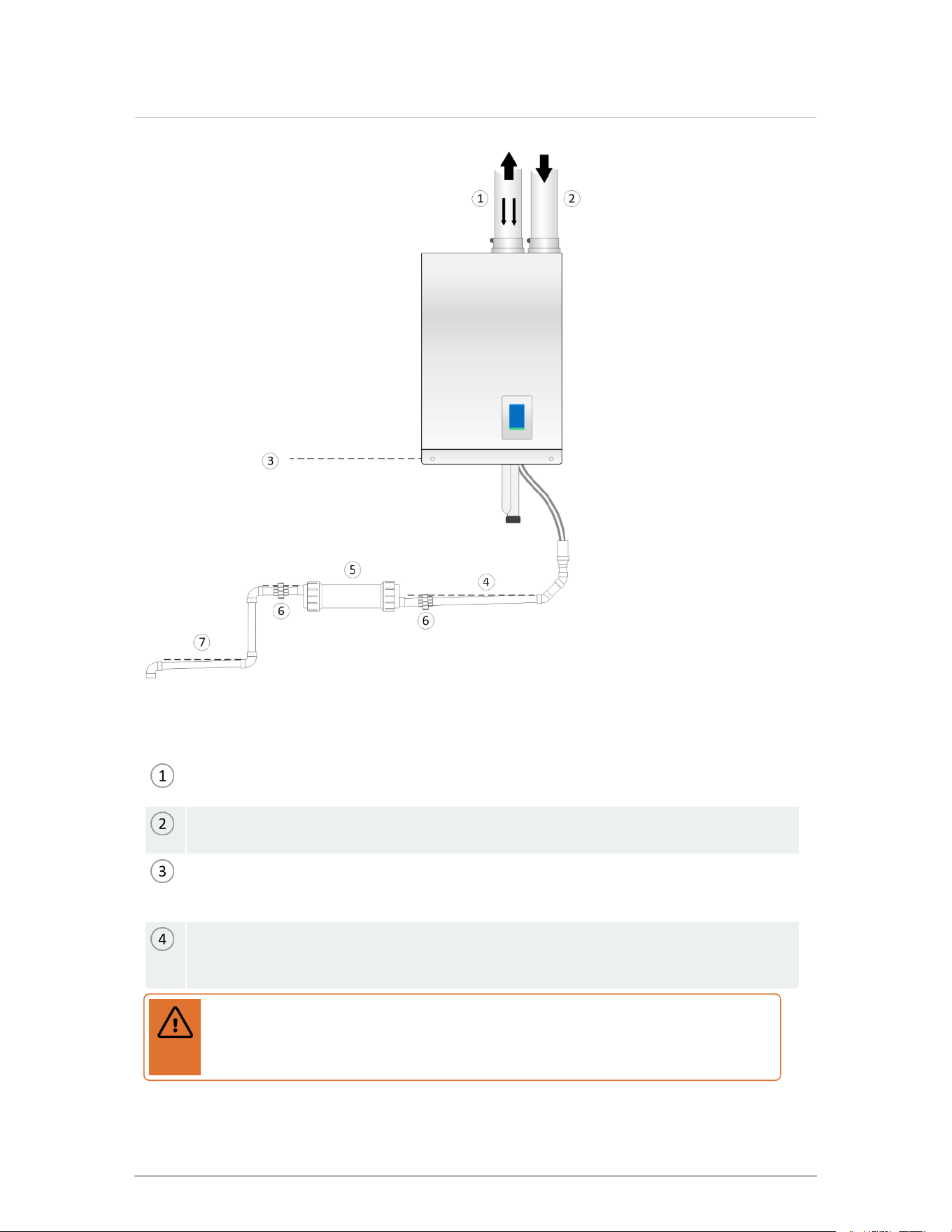
Figure 35 Condensate neutralization tank
Flue gas exhaust: condensate, and potentially rain water, flow back from the venting
system.
Air intake piping: fresh air supply for boiler. Ensure that rain water cannot enter air intake
to avoid damage to the appliance.
Condensate water line: All condensate discharge lines, including neutralization tank inlet,
must be at a lower elevation than the condensate water line of the appliance to avoid
damage to the appliance.
Free flow of condensate from venting systems and the pressure vessel must be
maintained at all times. Trap and condensate drain piping must be accessible to allow
regular inspection and cleaning.
Warning
Risk of injury. Tank fluid can be highly acidic. Do not use hands to stir material.
Refer to the neutralization instructions of the manufacturer.
36
Section: Installation
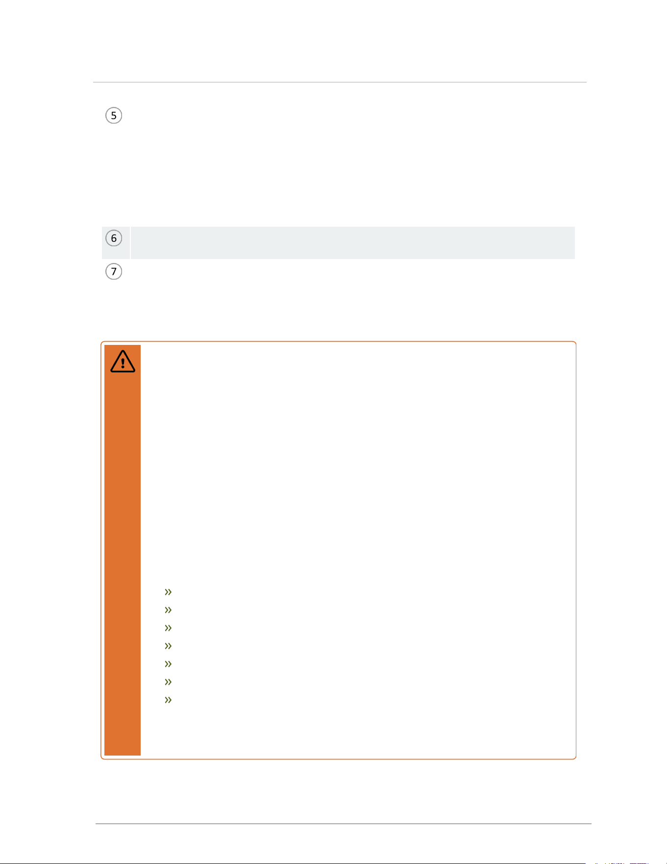
Condensate neutralizer: Drain materials subject to corrosion must be protected by acid
neutralization.
Access to the discharge, before the drain, is necessary for proper maintenance in order to
check the effectiveness of the neutralizing agent. A simple pH test should be performed
annually to ensure neutralizing agent is still effective. If the pH falls below 6.5 the neutralizing
material should be replaced. The agent (limestone chips with a minimum calcium carbonate
content of 85%) can be purchased from a local supplier.
¾" FPT inlet and outlet. Unions for ease of maintenance (ships with shown model NT-1S,
available from plumbing supply houses).
To drain. Confirm slope. Slope the condensate hose and drain piping toward the drain and
secure to prevent accidental disassembly.
4.11 Water Piping
Warning
Water quality has a significant impact on the lifetime and performance of a boiler's heat
exchanger.
Improperly prepared water in a heating circuit may cause damage to the heat exchanger
through fouling or corrosion. Repeated or uncontrolled water fills will increase the
potential for damage.
High levels of dissolved solids or minerals may precipitate out of the fluid onto the hottest
part of the heat exchanger, impairing heat transfer and resulting in overheating and
premature failure. The amount of solids that may form on the heat exchanger will depend
on the degree of hardness and the total water volume in the system. A high water volume
system with a low hardness count may cause as much damage as a system with less
volume and higher hardness, so for high-volume systems it is recommended to reduce
dissolved solids to 10 ppm - 30 ppm before the introduction of inhibitors and / or glycol.
Final water chemistry limits are as follows:
Hardness to be between 1 and 9 grains
TDS is to be between 10 and 150 ppm
Acidity pH is to be between 6.6 and 8.5
Chloride is to be less than 125 mg/l
Iron is to be less than 0.3 mg/l
Cu less than 0.1 mg/l
Conductivity is to be between 20 and 300 μS/cm at 77°F (25°C)
Important: Ensure that these limits are acceptable for the other water-side components
in the system.
37
4.11 Water Piping

Boiler Head Loss - 110,000 BTU/hr
Flow rate (gpm) 2 4 6 8 10 12 14
Head @ flow (ft) 0.18 0.51 0.99 1.59 2.49 3.55 4.75
Table 9 Boiler Model 110 Head Loss
Boiler Head Loss - 150,000 BTU/hr
Flow rate (gpm) 4 6 8 10 12 14 16
Head @ flow (ft) 0.42 0.9 1.52 2.26 3.25 4.31 5.61
Table 10 Boiler Model 150 Head Loss
Boiler Head Loss - 199,000 BTU/hr
Flow rate (gpm) 4 7 10 13 16 19 22
Head @ flow (ft) 0.44 0.9 1.73 2.91 4.36 6.23 8.4
Table 11 Boiler Model 199 Head Loss
Ensure that the pump is rated for the design circulating water temperatures; some pumps have a
minimum water temperature rating above the low temperature potential of the boiler. Following
installation, confirm the actual performance by measuring Δ°T (under high and low flow
conditions) after establishing the correct firing rate.
After a call for heat is satisfied, there can be a significant amount of residual heat contained in the
heat exchanger. This residual heat is utilized by a feature called pump post-purge. Default
settings will run the primary pump for up to 5 minutes after a call for heat is completed. Secondary
pumps can be configured to run up to 15 minutes after a call for heat is completed. However,
secondary pumps should only be configured to do so when zone valves are not used, as this will
protect the pump from deadheading when the zone valves are closed.
In order for built-in pump-purge to operate, boiler and system pumps must be wired to boiler. To
allow pump purge after burner shut-down, the primary pump must be under the control of the
boiler.
38
Section: Installation
Propylene glycol usage
Warning
Do not use automotive-type ethylene or other types of automotive glycol antifreeze, or
undiluted antifreeze of any kind. This may result in severe boiler damage. Installers must
ensure that glycol solutions are formulated to inhibit corrosion in hydronic heating
systems of mixed materials. Improper mixtures and chemical additives may cause
damage to ferrous and non-ferrous components as well as non-metallic, wetted
components, normally found in hydronic systems. Ethylene glycol is toxic, and may be
prohibited for use by codes applicable to your installation location. For environmental and
toxicity reasons, it is recommended to only use non-toxic propylene glycol.
Propylene glycol solution is commonly used in a closed loop where freeze protection is required. Its
specific gravity is lower than that of water, resulting in lower thermal performance at a given flow and
pressure. Generally, a 50:50 solution of glycol and water requires an increased system circulation
rate (gpm up 10%), and system head (up 20%) to provide performance equivalent to straight water.
These boilers are designed for use within a closed loop, forced circulation, low pressure system. A
30 psi pressure relief is supplied for field installation on the outlet piping. Relief valve discharge
piping must terminate between 6" (15 cm) and 12" (30 cm) above the floor or per local code.
Warning
During operation, the relief valve may discharge large amounts of steam and/or hot water.
To reduce the potential for bodily injury and property damage, install a discharge line that:
Is connected from the valve outlet with no intervening valve and directed
downward to a safe point of discharge.
Allows complete drainage of both the valve and the discharge line.
Is independently supported and securely anchored, so as to avoid applied stress
on the valve.
Is as short and straight as possible.
Terminates freely to atmosphere where any discharge will be clearly visible and is
at no risk of freezing. Terminates with a plain end which is not threaded.
Is constructed of a material suitable for exposure to temperatures of 375° F or
greater.
Is, over its entire length, of a pipe size equal to or greater than that of the valve
outlet (¾" NPT).
Do not cap, plug or obstruct the discharge pipe outlet.
39
4.11 Water Piping
4.11.1 General piping best practices
Primary/secondary piping, or the use of a hydraulic separator (such as the Caleffi 549 SEP4™
4-in-1 Magnetic Hydraulic Separators) is recommended for maximum flexibility in multi-load
applications. Piping loads in parallel is also encouraged in systems that only have two loads, or
when loads are operating simultaneously. The extremely low pressure drop through the heat
exchanger affords more flexible options unavailable in other designs.
Caution
Contact local water purveyors about the suitability of the supply for use in hydronic
heating systems. If unsure about water quality, request testing and assessment
(and treatment, if required) from a local water treatment expert. Alternatively, water
or hydronic fluid of known quality can be brought to the site.
4.11.2 System piping
Note
The piping drawings in this manual are simple schematic guides to a successful
installation. There are many necessary components not shown, and details such
as thermal traps are left out so the drawings have greater clarity. Boilers must be
installed by licensed and experienced heating professionals familiar with the
applicable local and national codes. System design is to be completed by an
experienced hydronic designer or engineer. You should carefully read and follow
the installation instructions along with the application drawing that fits your system.
System piping is connected to the boiler using 1" NPT-Male threaded fittings. To simplify
servicing, we recommend using unions at the boiler's supply and return water connections.
40
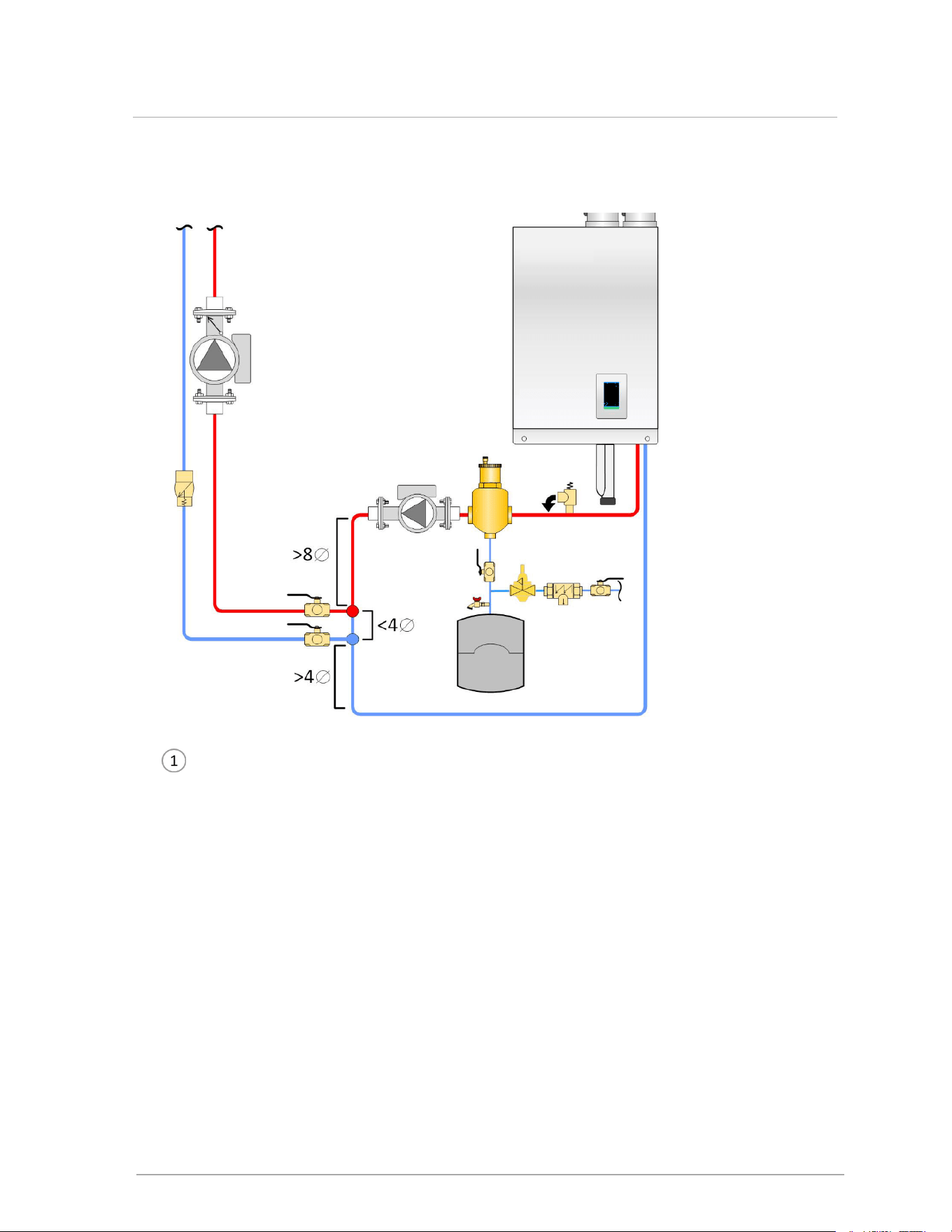
Section: Installation
Pressure relief valve (shipped with the boiler): no isolation valve permitted between
boiler and relief valve
Microbubble air eliminators should be installed as close as reasonably possible to the
supply outlet of the boiler.
Expansion tank connection (point of no pressure change) should be on the suction side
of the circulator, with minimal pressure drop between.
Fill station with isolation valve closed, or fill tank.
Boiler (primary) pump
To/ from load
Dirt separator recommended
Figure 36 Boiler trim options - single boiler
Fluid fill is most often accomplished by using a boiler regulator and fill valve set at 12 psig or
more, with the appropriate backflow prevention device as required by local code. This is
41
4.11.2 System piping
acceptable in areas where municipal water or well water has been treated and filtered to
remove excessive minerals and sediment, and water chemistry is known to be suitable for
closed loop hydronic systems. In areas where water quality is in question, or when chemical
treatment or glycol is required, other options should be considered. Follow the applicable
codes and good piping practice.
Warning
Close the fill valve after any addition of water to the system, to reduce risk of water
escaping.
Today there are a number of boiler feed and pressurization devices on the market that may
be a better choice than a raw water fill from the mains. When regular maintenance requires
relief valve blow-off, the discharge may be directed back into the pressurization appliance for
recycling of boiler fluid and chemicals back into the system. In buildings that may be
unoccupied for long periods of time, pressurization appliances are useful to prevent flood
damage should leakage occur from any component in the system. An additional benefit is
that backflow prevention devices are not required when using these devices.
Do not place any water connections above the boiler to avoid damage to the fan and controls.
If needed, create a shield over the top of the cover, but allow clearance for airflow and service
access.
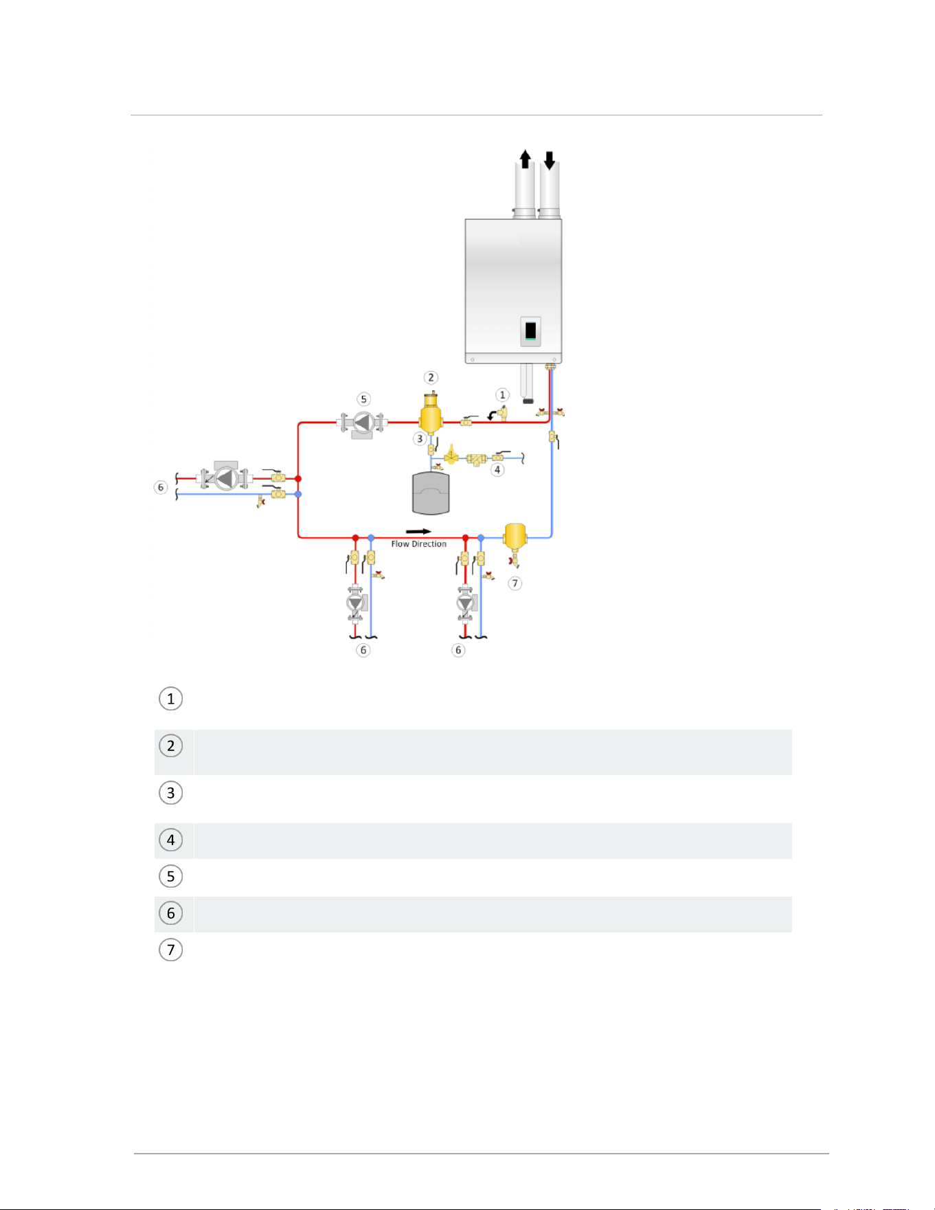
Primary-Secondary piping
For best results use a primary / secondary piping system ensuring that the boiler loop is
adequately sized. Primary / Secondary piping ensures adequate flow and de-couples Δ°T
issues (boiler vs. distribution). Aim for a 20°F to 30°F Δ°T across the heat exchanger at high
fire (there is a boiler protection throttle fence limiting the Δ°T to 40°F).
These boilers can supply four different heating loads within the temperature range of 34°F to
180°F to meet four separately-piped loads. Use closely spaced tees to connect each pumped
“load” (e.g. DHW, baseboards or radiant floor) to the primary loop. Alternatively, use a
hydraulic separator between the boiler loop and the system. As well, two load systems may
also be piped in parallel.
To ensure adequate water flow through the boiler under high-head / single-zone space
heating conditions, a pressure-activated bypass or other means of bypass must be used on
any load where the flow rate might drop below minimum requirements.
Ensure that the pump is rated for the design circulating water temperatures; some pumps
have a minimum water temperature rating above the low temperature potential of the boiler.
Following installation, confirm the actual performance by measuring Δ°T (under high and low
flow conditions).
Check valves or thermal traps should be used to isolate both the supply and return piping for
each load - to avoid thermal siphoning and reverse flow.
42
Section: Installation
In primary / secondary piping, the boiler pump is sized for the boiler loop only. For the Boiler Model
110 model, the heat exchanger head loss is only 1.5’ at 4 US gpm, and 2.5’ at 10 US gpm.
Closely-spaced tees: Install tees with straight piping (min. 8 x pipe diameter upstream
and 4 x pipe diameter downstream), with tees maximum 4 pipe diameters apart, with no
restrictions between fittings.
Figure 37 Primary-secondary piping details with closely-spaced tees
43
4.11.2 System piping
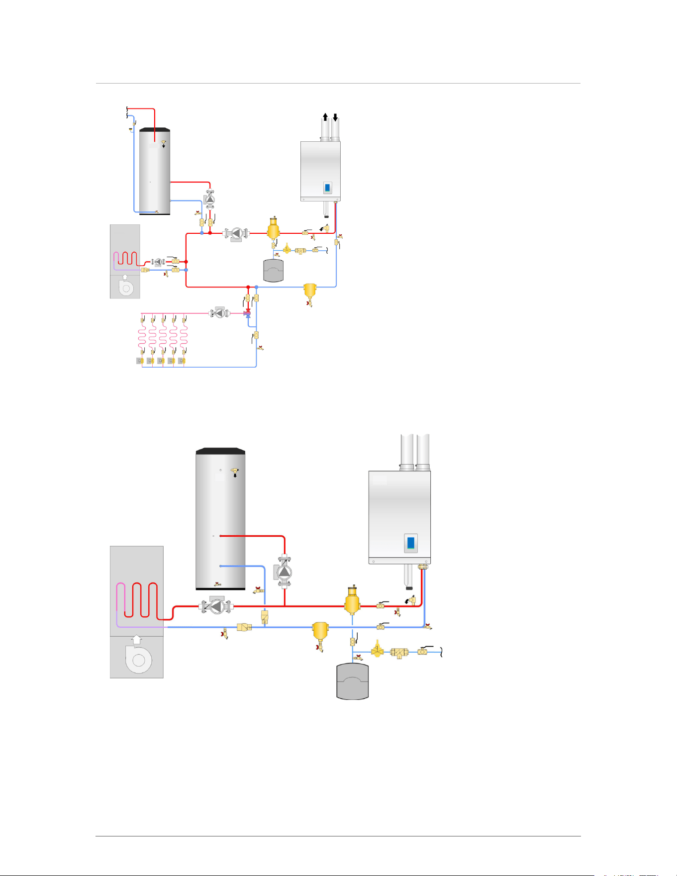
Figure 38 Primary-secondary piping with simultaneous heating calls
Figure 39 Two pump, two load - parallel piping concept
44
Section: Installation
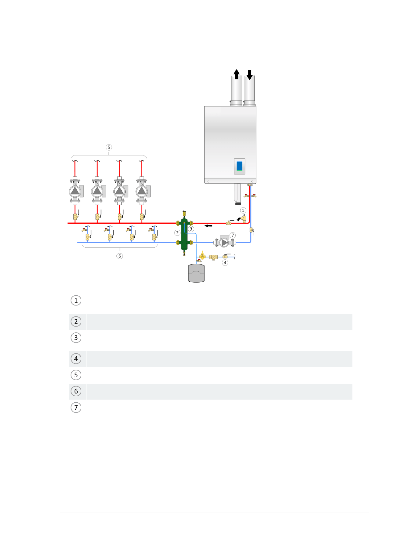
Pressure relief valve (shipped with boiler): no isolation valve permitted between boiler
and relief valve
Hydraulic separator
Expansion tank connection (point of no pressure change)should be on the suction side
of the circulator, with minimal pressure drop between.
Fill station with isolation valve closed, or fill tank
Supply piping to loads
Returns to loads
Boiler (primary)pump
Figure 40 Primary-Secondary piping concept with hydraulic separator
The boilers can supply multiple heating loads with compatible supply temperature requirements.
Always ensure that loads sensitive to high temperatures are protected using means such as
mixing valves.
45
4.11.2 System piping
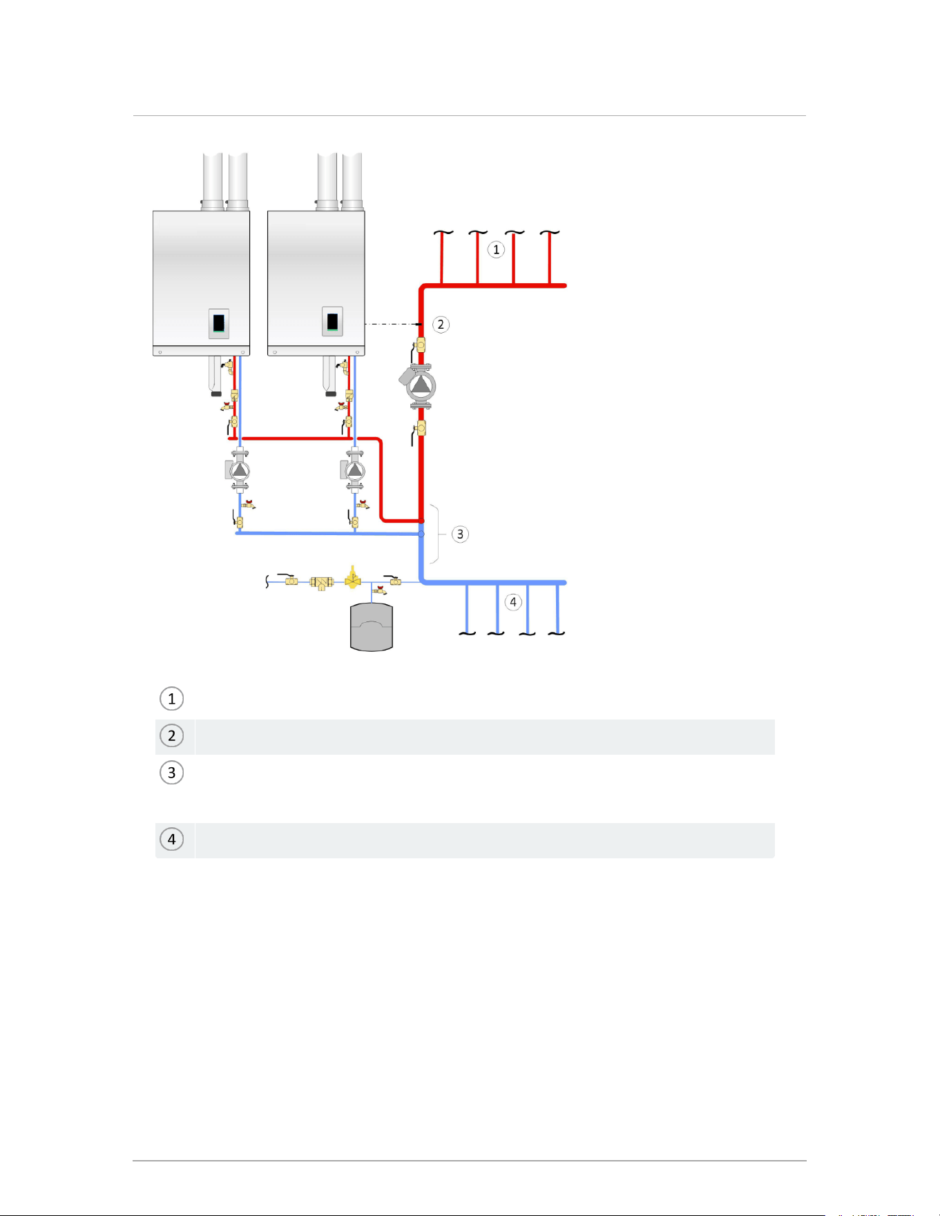
Supply to heating system.
Secondary loop sensor (to master boiler).
Closely-spaced tees are a maximum of four pipe diameters apart, with a minimum of
eight pipe diameters of straight piping upstream of the first tee and a minimum of four
pipe diameters of straight piping downstream of the second tee.
Return from heating system.
Figure 41 Multiple boiler piping
46
Section: Installation

4.12 Gas piping
Note
Due to the precision of modern modulating boilers it is important to pay special attention to
gas pressure regulation.
Important: Check gas supply pressure to each boiler with a manometer or other high-
quality precision measuring device. Pressure should be monitored before firing the boiler,
during operation throughout the boiler's full modulation range, and after the call when the
regulator is in a "lock-up" condition.
Pay special attention to retrofit situations where existing regulators may have an over-
sized orifice and/or worn seats, causing pressure “creep” and high lock-up pressures.
A high quality regulator will maintain constant pressure above the boiler’s minimum
specification at all firing rates, and will not exceed the boiler’s maximum pressure rating
when locked-up with no load.
4.12.1 Gas pressure
The boilers require a minimum inlet gas supply pressure of 4.0" w.c. for natural gas or propane
during high fire operation. For either fuel, the inlet pressure shall be no greater than 14.0" w.c.
Confirm this pressure range is available with your local gas supplier.
The inlet gas connection to the boiler is ½" NPT (female).
Adequate gas supply piping must be installed with no smaller than ½" Schedule 40 (e.g., Iron Pipe
Size (IPS) and using a 1" w.c. pressure drop, in accordance with the following chart.
Maximum Gas Pipe Length (ft)
Model ½" IPS ¾" IPS 1" IPS 1¼ " IPS
110,000 BTU/hr (natural gas) 30' 125' 400' 1,600
110,000 BTU/hr (propane) 90' 350' 1000' 2,000
150,000 BTU/hr (natural gas) 20' 80' 200' 900'
150,000 BTU/hr (propane) 50' 200' 600' 2,000'
199,000 BTU/hr (natural gas) 10' 40' 150' 900'
199,000 BTU/hr (propane) 30' 125' 400' 1,400'
Table 12 Maximum Gas Pipe Length (ft)
47
4.12 Gas piping
Gas piping must have a sediment trap ahead of the boiler’s gas valve. A manual shutoff valve
must be located outside the boiler, in accordance with local codes or standards. All threaded
joints in gas piping should be made with an approved piping compound resistant to the action of
natural gas or propane. Use proper hangers to support gas supply piping as per applicable
codes.
Install manual shut-off valve. Check local code for height requirement
Full-sized sediment trap
Union
Figure 42 Typical gas piping
The boiler must be disconnected or otherwise isolated from the gas supply during any pressure
testing of the system at test pressures in excess of ½ psig. Dissipate test pressure prior to
reconnecting. The boiler and its gas piping must be leak-tested before being placed into
operation.
The gas valve is provided with pressure taps to measure gas pressure upstream (supply
pressure) and downstream (manifold pressure) of the gas valve. Note that manifold pressure
varies slightly in accordance with firing rates with the modulating series boilers, but will always
be close to zero " wc.
4.13 Electrical connections
All electrical wiring to the boiler (including grounding) must conform to local electrical codes and/or
to the National Electrical Code, ANS/NFPA No. 70 – latest edition, or to the Canadian Electrical
Code, C22.1 - Part 1.
48
Section: Installation
4.13.1 Power management, quality and electrical protection
In areas of unreliable power, appropriate surge protectors and or power conditioning equipment
should be installed in power supply wiring circuits.
Note
The boiler (like any modern appliance that contains electronic equipment) must have a
“clean” power supply, and is susceptible to power surges and spikes, lightning strikes
and other forms of severe electrical “noise”. Power conditioning equipment (surge
protectors, APC or UPS devices) may be required in areas where power quality is
suspect.
In temporary or manual operation, for example in new construction heating, use a construction
thermostat or jumper with an in-line on/off switch for on/off management of the boiler. Do not turn off
the heat by removing power to the boiler. This will interrupt the moisture management routine (fan
turns at ultra-low RPM for 90 minutes after burner shutdown) resulting in serious damage to the
boiler. Treat the boiler like a computer, where you do not just pull the plug when done.
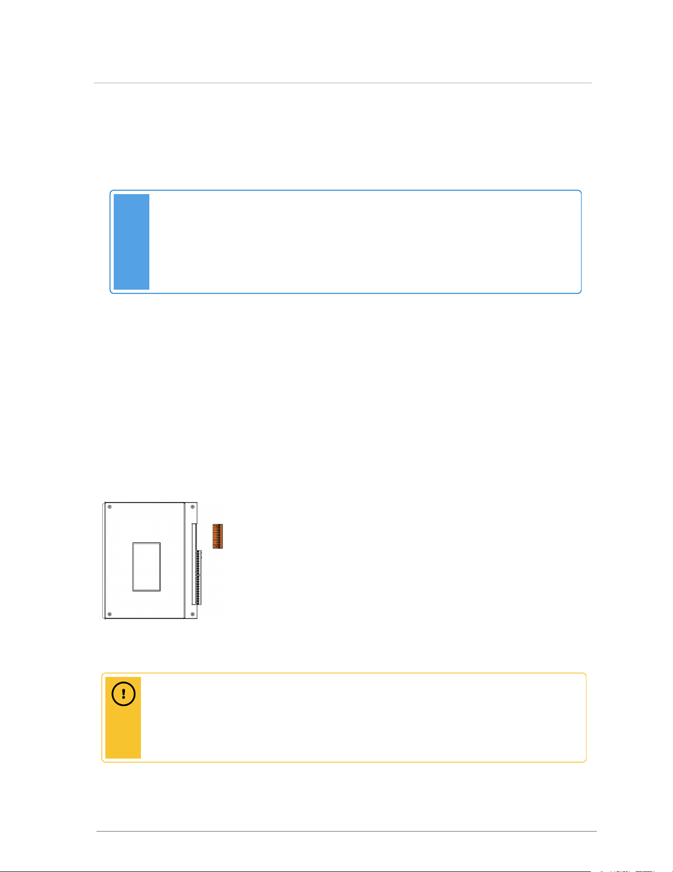
4.13.2 120VAC line-voltage hook-up
Line-voltage wiring is done within the field-wiring box (see Wiring diagrams on page 93). Connect the
boiler to the grid power using a separate, fused circuit and on/off switch within sight of the boiler. Use
14-gauge wire in BX cable or conduit properly anchored to the boiler case for mains supply and pump
circuits.
Figure 43 Line voltage load pump terminals
Caution
The on-board controller load pump relays are protected with five Amp fuses. The maximum
recommended load on each fuse is four Amps (80% of rating). The maximum combined
pump load is 10 Amps. Isolation relays or contactors must be used if the loads exceed
these maximums.
49
4.13.1 Power management, quality and electrical protection
Connect a 120VAC / 15 amp supply to the "AC IN" tagged leads in the wiring box. The maximum
actual draw (with five typical residential size pumps) is less than four Amp.
Boiler pump
The boiler (primary) pump is powered by the white/yellow wire from the pair labeled "Boiler Pump".
This lead is factory wired to the controller (and its 120 VAC supply) at the upper right backside of
the controller board. Do not attempt to connect the primary pump to the Pump/ Zone Valve
Terminal Block along the controller’s right edge - this is for the secondary pumps and/or zone
valves only. Connect the pump’s Black wire to the Yellow of this pair (switched Hot). The White/
Yellow pair should be individually capped if the primary pump does not obtain its power from this
pair (e.g. if a variable speed primary pump is connected to the mains power).
The VS Output leads are not commonly used, except when providing a boiler output signal to an
external direct digital control (DDC).
Load pumps
The 120 VAC power supply to the load pumps (P/V1, P/V2, P/V3, and P/V4) has been factory
installed and connected to P/V-L and P/V-N for your convenience. The upper four pairs of contacts
on this connector strip (labeled TB1) are then powered to manage up to 4 load pumps. Once the
controller is programmed for the respective loads, the boiler manages all the loads without need of
further relays, for loads up to 1/3 HP. For loads drawing over 1/3HP, use a protective relay..
Pumps can be switched on/off using the touchscreen controller, so there is no need for temporary
pump wiring during system filling / air purging.
Instructions for manual pump purge:
Warning
Ensure zone valves are open and system is not air-locked to avoid deadheading
pumps..
1. After defining loads, go to [More] > System Settings > Site Settings > In the Manual Pump
Purge field, set to "On". The manual pump purge runs until it is turned off, or until there is a
call for heat.
2. To shut off the manual pump purge, tap "On" to toggle to "Off"
The combined current of all load pumps connected through the on-board pump relays should not
exceed 10 amps. The control circuit board is protected using on-board field replaceable fuses.
Each pump is fused with a separate 5 Amp fuse. The Alarm contact is fused with a 5 Amp fuse and
the 24VAC boiler control circuit is protected with a 2 Amp fuse.
50
Section: Installation
4.13.3 Sensor and other wiring
Danger
Do not connect sensors to “Therm” terminals. Overheating components can result in
serious personal injury and/or property damage.
Other optional low voltage connections to the control board include:
Two auxiliary Interlocks - for external safety devices as may be required by some
jurisdictions, such as an external low-water cutoff.
Contacts for Indoor and Outdoor temperatures Sensors associated with reset heating. A
10K ohm thermister (resistor dependent on temperature) for outdoor reset sensing is
supplied with the boiler for improved comfort and combustion efficiency.
One pair for a DHW tank sensor. Connect to DHW S (not the respective Therm. 1,2,3,4
location) and the boiler automatically runs a smart DHW routine.
One pair of contacts for remote Secondary Loop temperature control.
One pair (marked BoilerNet) for network connection – this is used for connecting multiple
V10 controller appliances for autonomous staging.
The bottom pair of contacts (labeled External Control) receives a 0-10VDC (default) or 4-20
mA signal from an external boiler controller for direct throttle control. The boiler’s own
sensors act as high limits only. The user must enter maximum and minimum boiler supply
temperatures.
Note
Sensors connected to any sensor input contacts must be of the NTC 10k ohm type 2
thermistor with a resistance of 10,000 ohms at 77°F (25°C) and β = 3892. We do not
recommend using 3rd party supplied sensors. Compatible water temperature sensors
and outdoor sensors can be supplied by your distributor.
4.13.4 Thermostat wiring
Thermostat wiring
Each of the four loads has dry contacts for thermostats as marked on the lower connector strip (for
example, Therm 1 is associated with Load 1). Ensure that there are no disturbing influences on the
call-for-heat lines - for example, from being run in the same conduit as line voltage wires.
Most power stealing thermostats can be connected directly to the Therm terminals.
Caution: power-stealing thermostats
The V10 controller does not support power-stealing thermostats. Power stealing
thermostats take their operating power from the thermostat line. If a t-stat has electronic
display but does not use a C-wire or a battery, it is power-stealing.
51
4.13.3 Sensor and other wiring
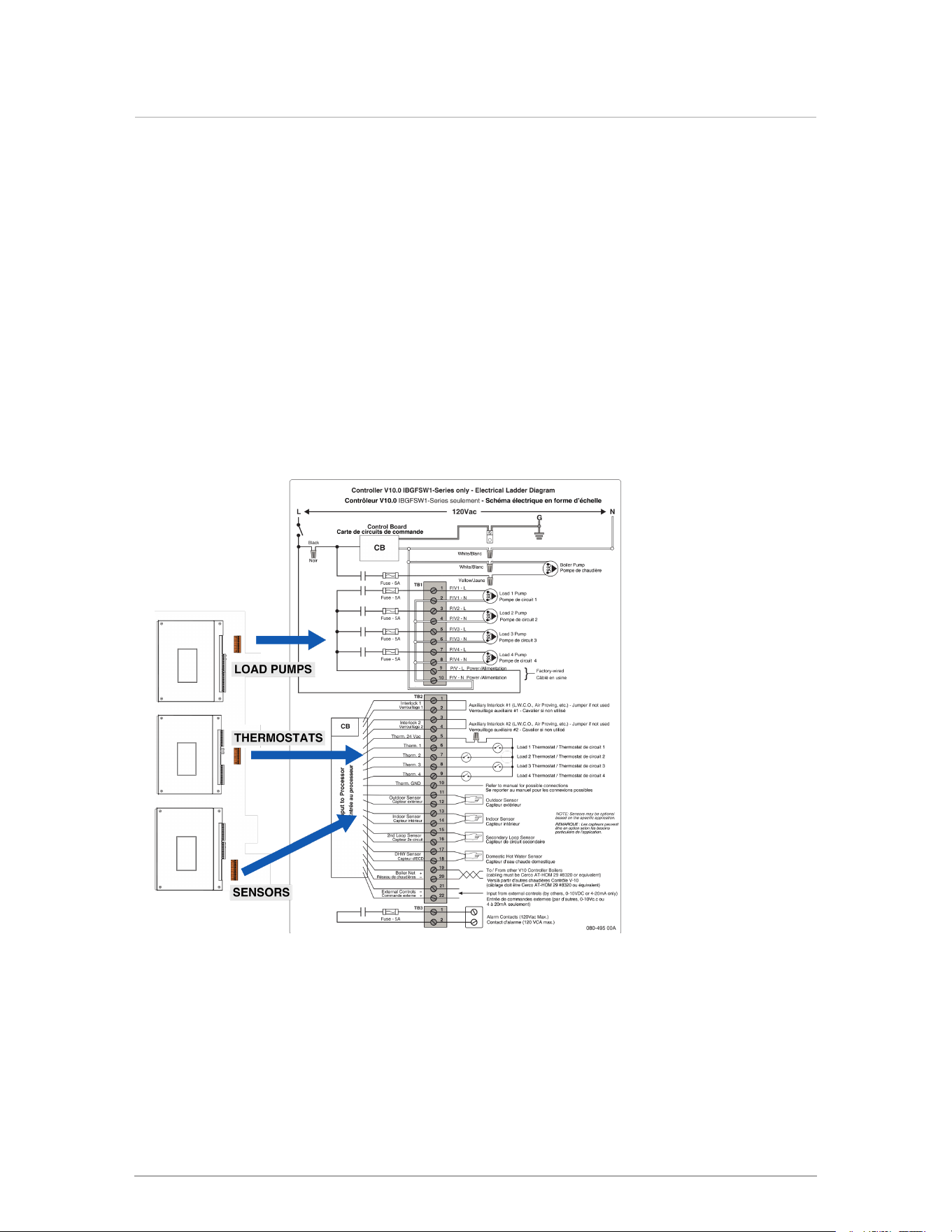
When the thermostats are being used to energize zone valves, the end switch of the zone valve
can be wired back to the therm connections. For multi-zoned loads, the end switches can be
ganged together and wired to a single therm connection.
When wiring thermostats directly to the V10, ensure no other electrical components are wired in
series with the thermostat, such as relay coils or zone valves. Consult the V10 Controller manual
for more detailed instructions.
4.13.5 Thermostat heat anticipator
"Therm” contacts draw no power, so an thermoostat anticipator setting of zero is applicable for
the V10. In the case of a single temperature / heat load where zone valves are used to manage
individual thermostatically controlled zones, each room thermostat’s heat anticipator should be
adjusted to the current draw of its associated zone valve.
Figure 44 Electric wiring connections
52
Section: Installation
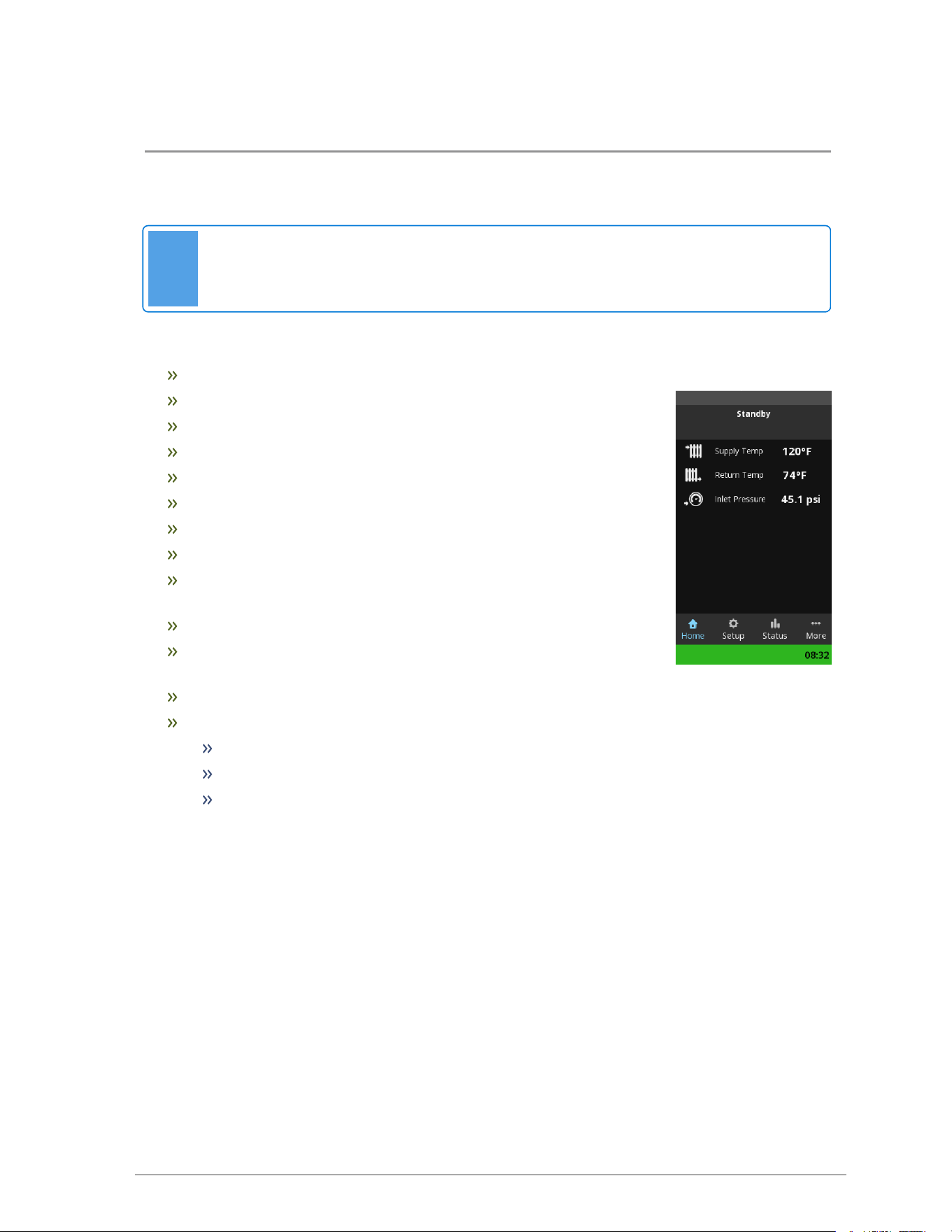
53
5.0 About the boiler controller
This boiler is equipped with a touchscreen controller for programming the boiler. For detailed
instructions on using the controller, see the Touchscreen Controller manual.
Note
Use only a stylus or a clean finger to interact with the touchscreen. Using sharp or metallic
objects will cause damage.
The controller is equipped to provide:
Control of up to five pumps – one boiler pump + four separate load pumps
Outdoor Reset control
Set Point temperature regulation
Domestic Hot Water (DHW)
External control using 0-10VDC or 4-20mA signal
Manual control of firing rate for gas valve calibration
Alarm dry contacts
Zoning - simultaneous operation of up to four pumps
Load Combining – simultaneous operation of two similar water
temperature loads
Programmable setback / override schedule
The control can manage or operate in a network of up to four V10
contoller boilers without additional controller
Connectivity with Sky-35 controller.
Features available in the touchscreen control include:
Setup Menu for simple, quick programming
Superior warning messages while setting up the control
Advanced Error messages with visual display on the Home Screen
5.1 Controller
When the boiler is first energized, the controller will go through a power up sequence that will take
approximately 60 seconds. During this time the controller is completing a self-diagnostic and loading
all previous settings. In the event of a power interruption the boiler will automatically resume operation
when power is restored with all the previously stored values.
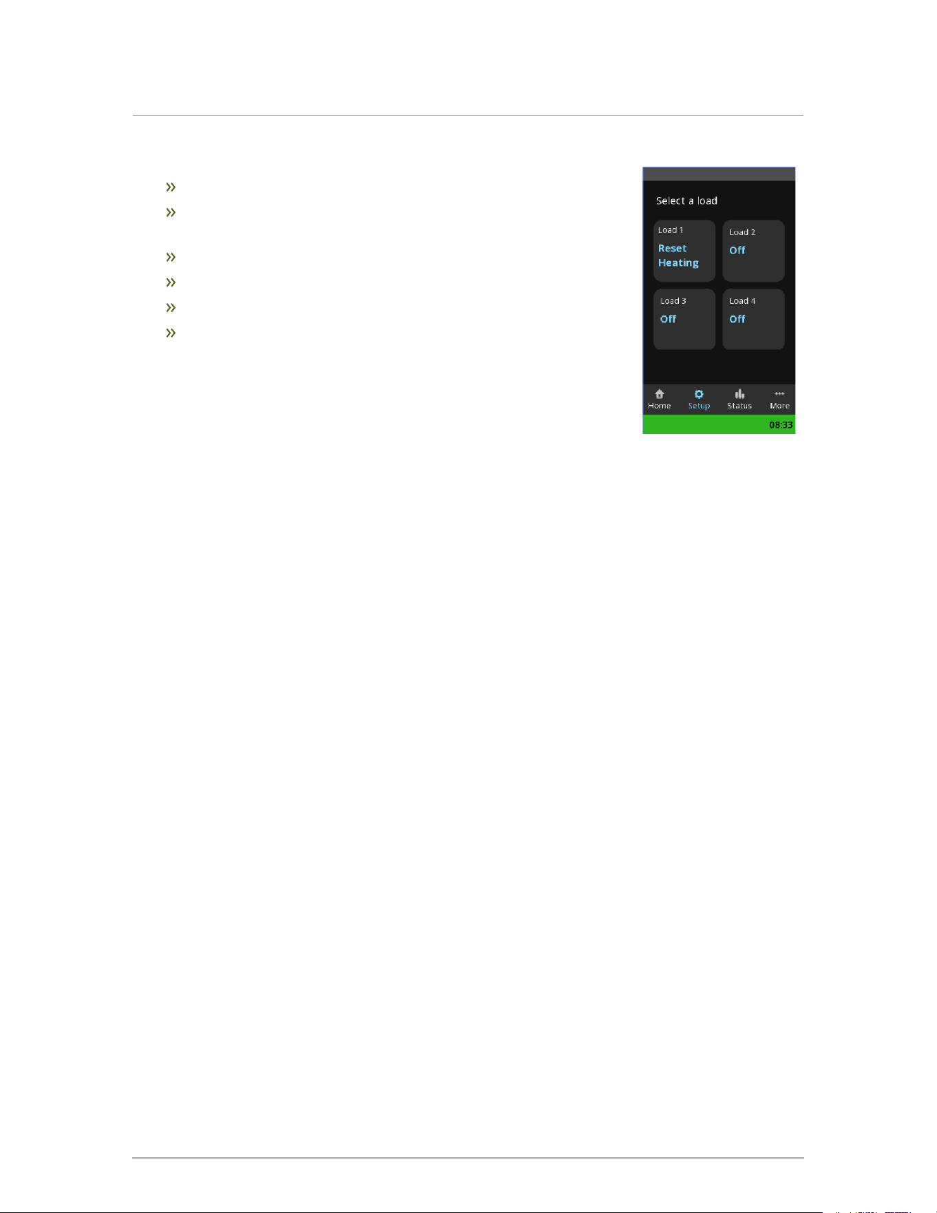
The controller provides overall management of the boiler operations including:
Power-up, self-diagnostics, easy Load parameter adjustments
Burner operation, safety management systems, call-for-heat
management and load priority
Real time boiler data
Temperature and throttle operation
Maintenance of operational and error service logs
2-way communication with other V10 controller boilers
Operational and historical data may be accessed from the Status menu >
Load Status > Load Profiles and Load Statistics screens. Also in the
Status menu, you can view error logs, including records of all errors since
original power-up complete with the date and time of the error.
5.2 Control interface
The control interface is provided through a color touchscreen display. The touchscreen responds
to a light finger touch on the screen. You can also use a stylus, pencil, or similar device to operate
the touch controls. Do not use a sharp or metallic object such as a screw driver to operate the
control as it could damage the touchscreen.
Prior to any interaction with the touchscreen, the display shows the Home screen details of the
current boiler status. If the controller is not interacted with for 10 minutes the display dims to save
power. The power saving display feature is user adjustable and is set to 10 minutes by default.
The control automatically returns to the home screen if left unattended. The screens will step back
one screen at a time in 10-minute increments if the touchscreen has not been touched. The pop-
up windows will also step back automatically in 2-minute intervals.
The boiler status bar indicates if the boiler is in a normal, warning or alarm state. When no warning
or alarm state is present, the bar will be green and the time will be displayed inside the green area.
The bar can also be yellow or red corresponding a warning or alarm state. Text inside the bar will
indicate the specific warning or alarm present. If more than one alarm is present the text display
will slowly change, rotating though the alarms that are present.
54
Section: About the boiler controller
55
6.0 Before operating the boiler
Danger
Do not store or use gasoline or other flammable vapors or liquids in the vicinity of this or
any other appliance. If you smell gas vapors, do not try to operate any appliance - do not
touch any electrical switch or use any phone in the building. Immediately, call the gas
supplier from a phone located remotely. Follow the gas supplier’s instructions, or if the
supplier is unavailable, contact the fire department.
Do not use this boiler if any part has been under water. Immediately call a qualified service
technician to inspect the boiler and to replace any part of the control system and any gas
control that has been under water.
Should overheating occur or the gas supply fails to shut off, do not turn off or disconnect the
electrical supply to the pump. Instead shut off the gas supply at a location external to the
appliance.
Important pre-ignition checks
Once installation of the appliance is completed, and before operating the appliance, it is important to
review the following checklist of precautions:
Checklist for electrical conditions, ducting and water connections
Checking electrical conditions Check
Check all line voltage electrical connections to ensure all connections are correct and tight.
□
Check thermostat connections.
□
Thermostat in a suitable location.
□
Checking venting connections Check
All vent pipe are installed in the correct size and that joints are sealed.
□
Confirm any common venting system at the installation site is isolated and independent of
the boiler.
□
Confirm that any holes left from the removal of a previous boiler have been sealed, and
that any resizing of the old flue has been done.
□
Checking piping connections Check
Check that the water piping system is fully flushed and charged, and that all air has been
discharged through loosened bleed caps.
Note that it is possible to run all pumps from the touchscreen – without a call for heat. This
simplifies system filling and air bleeding (refer to "Performing a manual pump purge" in the
Controller manual). Load must be assigned. Use a minimum water pressure of 12 psig and
confirm that the pressure relief valve is installed and safely drained.
□
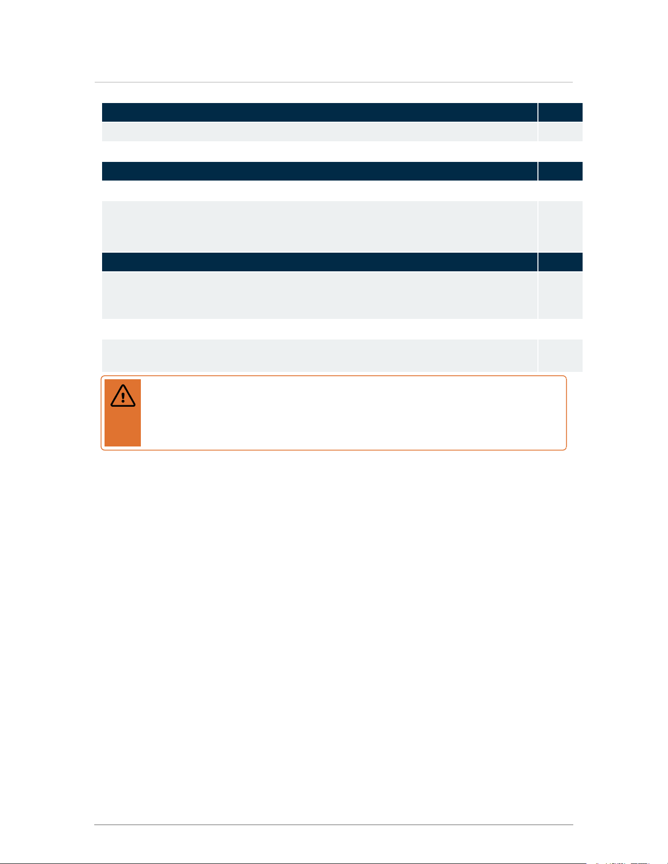
Checking electrical conditions Check
All connections are pressure-tested and leak free.
□
Check the external pump is flowing in the correct direction.
□
Checking gas connections Check
All connections are pressure tested and leak free.
□
Check to see that adequate gas pressure is present at the inlet gas supply test port.
Connect a manometer and open the gas control valve. Requirements are minimum 4" w.c
and maximum 14" w.c.
□
Powering on the Boiler Check
The installer must verify that at least one carbon monoxide alarm has been installed within
a residential living space or home following the alarm manufacturer’s instructions and
applicable local codes before putting the appliance into operation.
□
Boiler door must be in place during normal operation.
□
Perform a final check of electrical wiring, and provide power to the boiler to initialize
operation.
□
Warning
Fill the condensate trap with water before you first fire the boiler to prevent exhaust
fumes from entering the room. Never operate the boiler unless the trap is filled with
water. Failure to comply will result in severe personal injury or death.
56
Section: Before operating the boiler
57
7.0 Boiler operation
Before operating the appliance, there are some important pre-igntion checks that need to be
performed. For more information, see Before operating the boiler on page 55. To understand the
boiler start-up process, see Sequence of Operation on page 95. If the sight glass viewport clouds up
at start-up, see Cleaning the sight glass on page 77.
7.1 Lighting and shutting down the boiler

Start-up Checklist Check
Followed lighting and shutting down procedure.
□
Tested the ignition safety shutoff function (see Testing the ignition safety shutoff).
□
Checked the appliance's fuel source, and if necessary, performed a fuel conversion
using the appropriate P-kit.
□
Performed gas pressure test by measuring the inlet gas pressure.
□
Tested efficiency of the appliance and made necessary adjustments by Performing a
combustion test and adjustment.
□
Tested the low water cutoff function to check that the LWCO sensor is working. See
Testing the LWCO function on page 64.
□
Tested the high limit temperature function to check that the High limit temperature
sensor is working. See Testing the Hi-Limit cutoff temperature function on page 65.
□
7.2 Testing the ignition safety shutoff
To test the ignition system safety shutoff function:
1. With the boiler in operation, shut off the gas control valve directly outside the boiler case.
2.
The controller will cycle through purging and igniting three times. When the ignition
attempt is unsuccessful, Ignition Trials Exceeded will be displayed in red on the bottom of
the screen.
3.
On the touchscreen controller tap (Status)> Clear Errors > Yes.
7.3 Commissioning
The appliances are factory calibrated to operate with natural gas (or propane if desired) at sea
level. The gas-air ratio or zero-offset adjustment screw may need adjusting to attain optimum
combustion results. Note that only qualified technicians using properly functioning and calibrated
combustion analyzing equipment should perform a mixture adjustment.
58
Section: Boiler operation
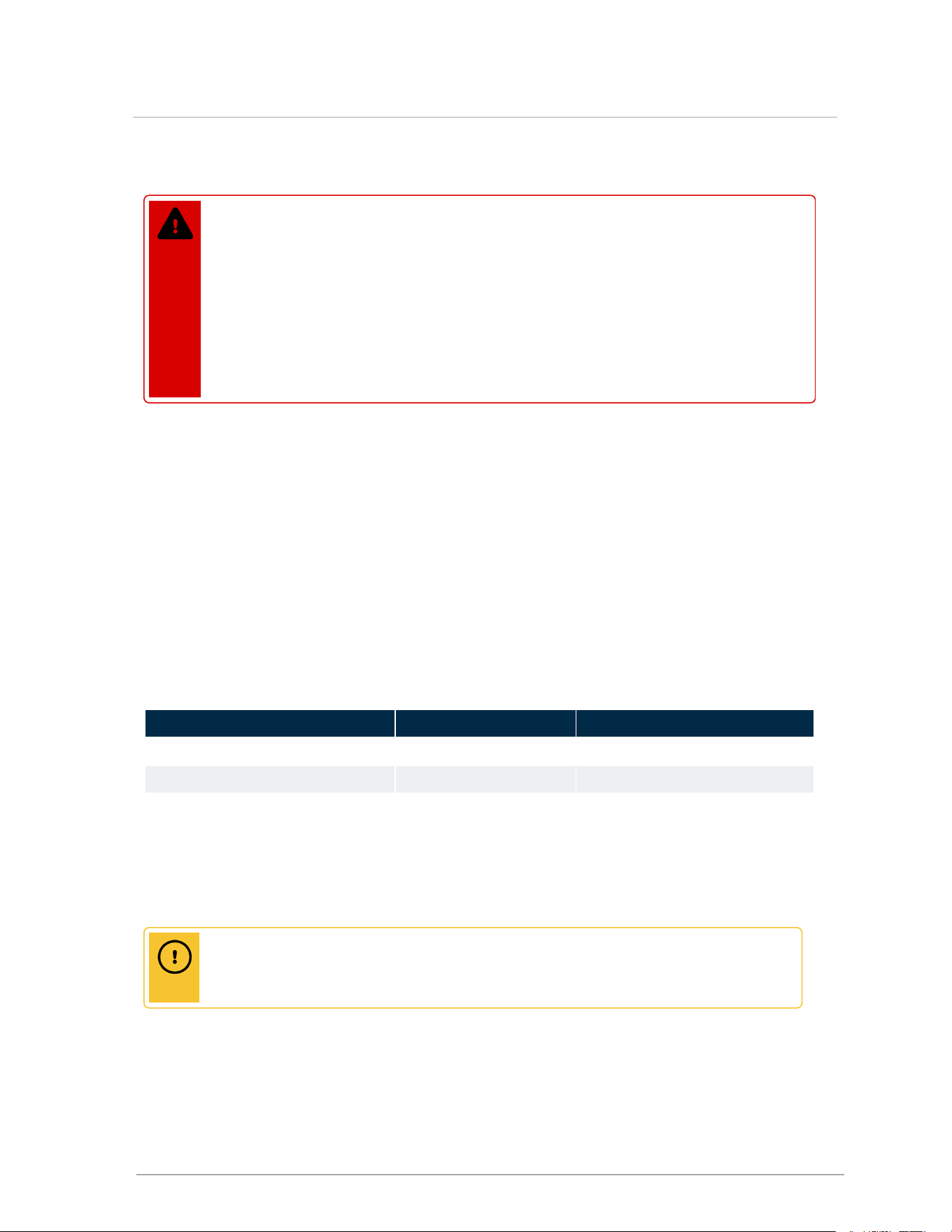
7.3.1 Checking a boiler's fuel source
Danger
Operating any appliance using a fuel other than the fuel listed on its rating plate is
prohibited. Failure to follow the instructions on converting to alternate fuels can result in
a fire or explosion, which may cause property damage, personal injury, or loss of life.
Check the rating plate of the appliance to ensure it is configured for the fuel you are
using. If the fuel is incorrect for the appliance, a conversion kit must be ordered and the
gas valve adjusted accordingly. Failure to perform the required fuel conversion can
result in an immediate hazard.
This boiler model can burn either natural gas or propane if equipped with the correct fuel-air
metering device. Examine the rating plate of the boiler to ensure it is configured for the fuel you are
using. For example, if the boiler is configured for natural gas, but needs to be converted to propane,
use the conversion kit to install the appropriate fitting(s) and adjust the gas valve accordingly. See
Table 13 for the required conversion kit.
The V10 touchscreen controller will automatically detect the installation’s altitude and make the
appropriate adjustments to operate the boiler up to 4,500 feet in elevation without de-ration. The
boiler will automatically de-rate at altitudes above 4,500 feet.
Fuel conversion kit numbers
Compare the boiler model number with the Kit # found in the table below:
Model Number to Propane to Natural Gas
Boiler Model 110
P-1500 P-1501
Boiler Model 150
P-1502 P-1503
Boiler Model 199
P-1504 P-1505
Table 13 Fuel Conversion Kits
7.3.2 Performing a fuel conversion
Caution
The gas supply shall be shut off prior to disconnecting the electrical power, before
proceeding with the conversion.
You must be a qualified heating professional to perform this procedure. In this fuel conversion, you
will be replacing the orifice, located between the gas valve and gas line to the fan, with the fuel-
appropriate orifice supplied in the kit.
59
7.3.1 Checking a boiler's fuel source
To perform a fuel conversion:
1. Turn off the gas supply.
2. Change the gas fuel source.
3. Before you disconnect the electrical power, shut off the gas supply at the gas shut-off
valve.
4. Disconnect the electrical power.
5. Remove the front door cover.
6.
Remove the top panel of the appliance to access the gas valve.
7. Undo the union nut connecting the gas line to the gas valve (gas valve outlet).
8. Remove the O-ring and orifice.
9. Place the fuel-appropriate orifice (supplied in the kit) into the O-ring, and re-install.
10. Tighten the union nut at the gas valve outlet.
11. Reinstall the top panel.
12. Restore the gas supply by opening the gas control valve and reconnect the electrical
power.
13. Perform a combustion test (see instructions below).
14. When the boiler is running, use an approved leak detection solution to soap test all joints.
15.
Place conversion labels associated with the new fuel onto the boiler.
7.3.3 Adjusting the gas valve
Danger
Making adjustments to the gas valve without a properly calibrated gas combustion
analyzer and by persons who are not trained and experienced in its use is forbidden.
Failure to use an analyzer can result in an immediate hazard.
60
Section: Boiler operation
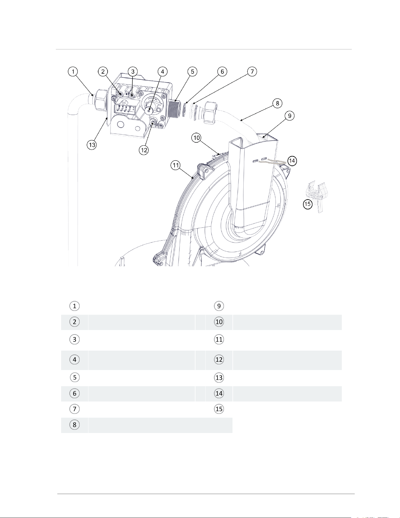
Figure 45 Gas valve and fan components
Gas valve inlet Fan inlet
Inlet gas pressure test port Fan plug
Manifold gas pressure test port (not
for field use)
Fan
Low fire adjustment (offset
pressure)
High Fire Adjustment
Gas valve outlet Gas valve support bracket
Orifice Venturi insert clip
O-ring Venturi insert
Gas valve outlet pipe
61
7.3.3 Adjusting the gas valve
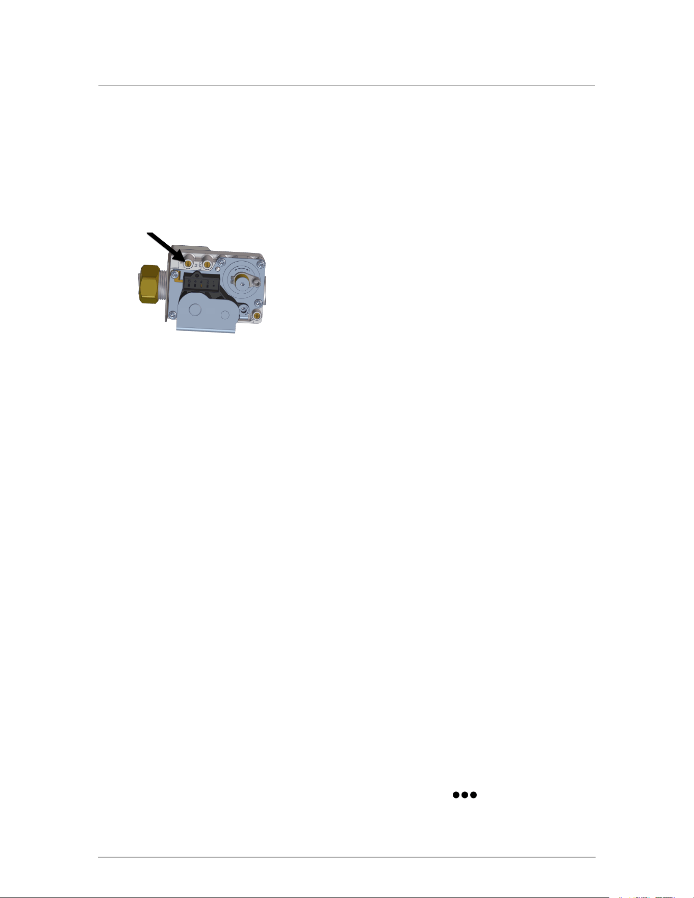
Measuring the inlet gas pressure
To perform a gas pressure test, you will need to use a Torx 15 screwdriver and a manometer.
1. Shut off the gas supply. You will be measuring the inlet gas supply from the test port (see
Figure 46 ). Do not perform a test from the manifold gas pressure test port.
2.
On the gas valve, loosen the inlet gas pressure test port screw counter-clockwise.
Figure 46 Location of inlet gas pressure test port
3. Attach the manometer to the inlet gas pressure test port.
4. To measure the inlet gas pressure, switch on the gas supply and record the static
pressure.
5. Give the boiler a call for heat.
6. To run the boiler at high fire, you can set the heat-out value in Test Operation mode to the
maximum MBH for the boiler. To do this, on the controller, go to >Test Operation > In the
Fan Test: Heat Outfield, tap 0 MBtu, then enter the maximum MBH. Record the working
pressure.
7. Typical static gas pressure for Natural Gas is 7" wc and 11" wc for propane. Working
pressure should be no more than 1" wc less than static pressure.
8. After completing the inlet gas pressure test, switch off the gas supply.
9. Remove the manometer from the inlet gas pressure test port.
10. Tighten inlet gas pressure test port screw.
11. Switch on the gas supply, and return the boiler to normal operation.
Performing a combustion test and adjustment
The High Fire (gas-air ratio) adjustment screw will have to be adjusted to attain optimum
combustion results whenever fuel conversion is undertaken, however, no mixture adjustment
must be performed unless done by a qualified technician using properly functioning and
calibrated combustion analyzing equipment.
1. Turn on the boiler’s external gas shut-off valve.
2. Give the boiler a call for heat.
3. To run the boiler at high fire, you can set the heat-out value in Test Operation mode to the
maximum MBH for the boiler. To do this, on the controller, go to > Test Operation >
62
Section: Boiler operation
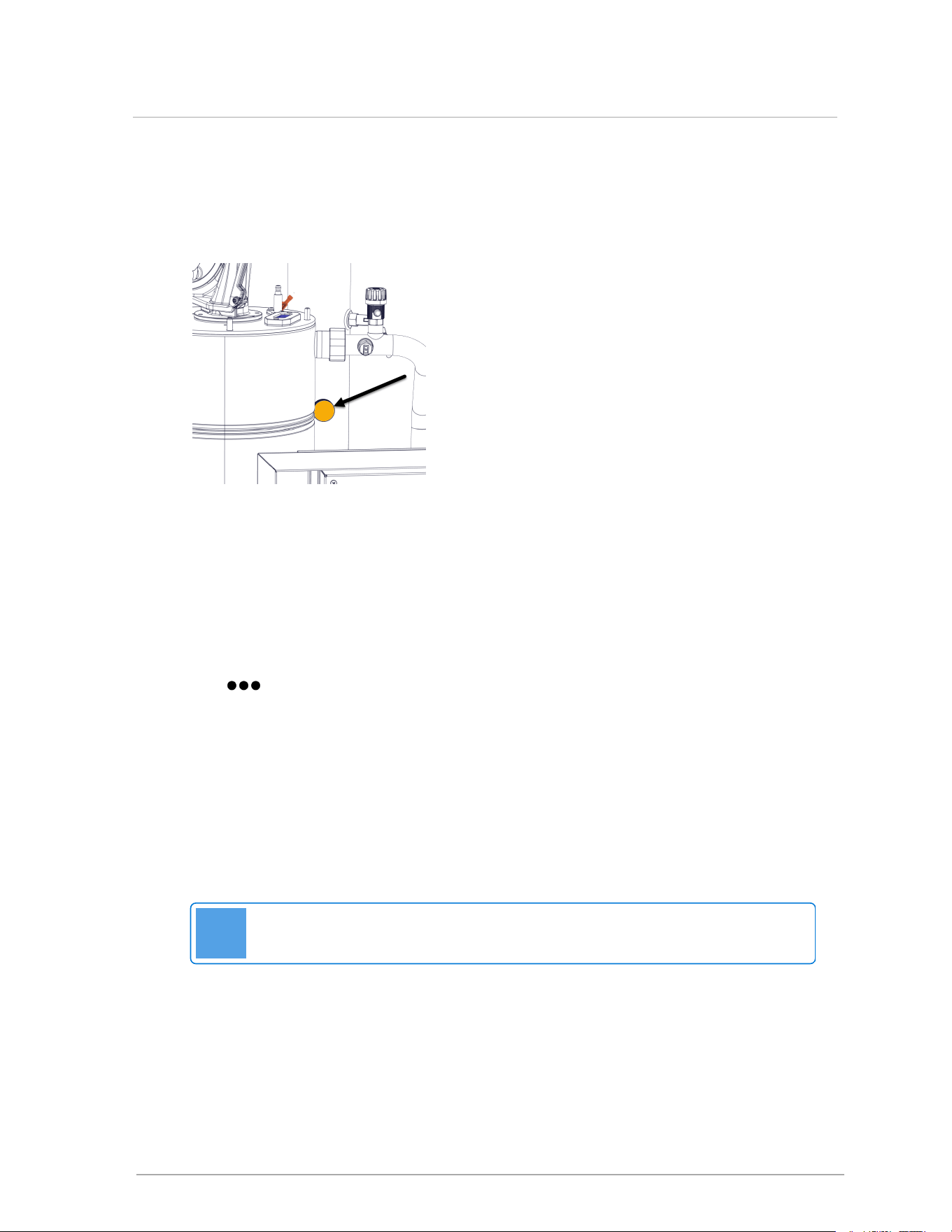
In the Fan Test: Heat Out field, tap 0 MBtu, then enter the maximum MBH.
When the boiler reaches high fire, insert the combustion analyzer test probe into the flue gas
test port. Then verify that the CO2 reading is within the combustion test targets at
Table 14
values.
Figure 47 Flue gas test port
4. Adjust the high fire according to values in Table 14 using a Torx 15 screwdriver. Turn the
screwdriver clockwise no more than a maximum of one full rotation at a time to raise the
CO
2
% (to richen). Turn counter-clockwise no more than a maximum of one full rotation at a
time to lower CO
2
%.
5.
Set the heat-out value in Test Operation mode to the minimum MBH for the boiler. To do this,
go to > Test Operation > In the Fan Test: Heat Out field, tap 0 MBtu, then enter the
minimum MBH.
6. Adjust the low fire according to values in Table 14 using a Torx 15 screwdriver. Turn the
screwdriver clockwise to raise the CO
2
% (to richen). Turn counter-clockwise to lower
CO
2
%. Start with ⅛ of a turn until you see the analyzer measure a change then only make
1/16 adjustments. If changing direction on this adjustment you may notice a significant
backlash. Do not over-adjust.
7.
Check the results and confirm the correct settings when you return the boiler to high fire, and
then to low fire.
Note
For Natural Gas, clock the gas meter to confirm full maximum rating plate input.
8. To exit the Test Operation screen, select Back.
9. Remove the call for heat.
63
7.3.3 Adjusting the gas valve

10. If a manometer is connected to the gas valve inlet gas pressure port:
a. Turn off the gas supply at the external gas shut-off valve.
b. Disconnect the manometer.
c. Tighten the inlet pressure port screw with a Torx 15 screwdriver.
11. Remove the analyzer probe, and install the test port plug.
12. Turn on the gas supply shut off valve.
Fuel
High fire CO
2
Low fire CO
2
CO
max
PPM
Range Target
Range Target
Natural Gas
8.9 % - 10.0 % 9.5 %
8.2 % - 9.2 % 8.7 %
<150
Propane
10.3 % - 11.3 % 10.8 %
9.3 % -10.3 % 9.8 %
< 250
Table 14 Combustion test target ranges - CO
2
/ Maximum CO
7.3.4 Testing the LWCO function
The low water cutoff (LWCO) function provides continuous protection against low water in the
boiler. If the SIM detects low water, the boiler enters a lockout state. Perform the test to ensure
that the LWCO sensor is functioning.
1.
Go to Status > SIM Menu > LWCO Test > Read the instructions.
2. After the test, on the touchscreen controller, select the Reset button.
The message: "The SIM Module has been reset" is displayed.
3. Tap Close > Back to exit the test.
64
Section: Boiler operation

7.3.5 Testing the Hi-Limit cutoff temperature function
The hi-limit temperature function monitors the maximum supply temperature set in the safety
ignition module (SIM). If the water temperature exceeds the hi-limit temperature, the boiler goes
into a lockout condition, requiring a manual reset. Perform the test to ensure that the water
temperature sensor is functioning.
To test the Hi-limit temperature function:
1.
Go to > SIM Menu > Hi-Limit Test > Read the instructions.
You will need to enter a cutoff temperature below the actual supply temperature value
currently displayed. For example, if the Supply Temp. value is 180°F, enter 170°F in
the Cut Off Temp. box.
2. In the Cut-Off Temp. field, enter a number value > OK.
The message: "Hi-Limit Detected" is displayed.
3. To reset the boiler, select the Reset button. The cutoff value reverts to normal upon reset.
The message: "The SIM module has been reset" is displayed.
4. Tap Close > Back to exit the test.
65
7.3.5 Testing the Hi-Limit cutoff temperature function

Intentionally left empty
67
8.0 Service and maintenance
Inspection of the boiler is to be performed annually by a qualified service technician.
Caution
The owner is responsible for general care of the boiler. Improper maintenance of the boiler
may result in a hazardous condition.
8.1 Maintenance checklist for homeowner
Maintenance Required Frequency Check
Inspect system for unusual noises or odors. Call your local heating
contractor for service if needed
As needed
□
Keep vent terminals clear of obstructions (snow, dirt, etc.). As needed
□
Keep combustible materials and flammable liquids and vapors away from
the boiler.
As needed
□
Check for signs of corrosion and deposits at venting transitions and
terminations, or the appearance of soot at the vent termination: any such
signs should be brought to the immediate attention of a qualified service
technician.
Monthly
□
Check system for signs of leaks. Monthly
□
Inspection of the boiler is to be performed annually by a qualified service
technician.
Annually
□
8.2 Maintenance checklist for heating contractor
Caution
Label all wires prior to disconnection when servicing controls. Wiring errors can cause
improper and dangerous operation.
Maintenance Required Check
Remove any obstructions (e.g. leaves, dust, other debris) from vent terminals
□
Check and clean or replace intake air filters or screens as required.
□
Check for holes or leaks in venting. Replace venting as needed.
□
Examine for any signs of moisture caused by sweating intake air pipes; insulate as
required.
□
Ensure proper resealing or re-installation of venting on each servicing.
□

Maintenance Required Check
Test Low-water cut-off (LWCO) safety operation on each servicing: see Testing LWCO
function in the Touchscreen Boiler Controller Manual.
□
8.2.1 Touchscreen boiler controller
Maintenance Required for Boiler Controller Frequency Check
Check that boiler operation is consistent with the steps in the
Touchscreen Boiler Controller Manual.
Annually
□
Check that water temperature targets and setpoint is satisfactory and
have not been adversely amended.
Annually
□
Check the operating history using the boiler's Logs menu and Error
Logs menu. The controller tracks the duty cycle of the boiler in each of
the loads separately. This information can be used to adjust the water
temperatures of each load.
As needed
□
8.3 Torque
Heat exchanger cleaning requires removal of the heat exchanger lid. The heat exchanger lids are
fastened by (depending on model) 4, 5 or 6 nuts. Upon reassembly these should be tightened,
using a cross pattern, to a torque between 50 inch•lb and 60 inch•lb.
8.4 General boiler maintenance
Boiler
Component
Maintenance Required Frequency Check
Condensate
trap
Remove and clean annually (see Cleaning the
condensate trap on page 78). Ensure that the trap
has been re-filled completely before firing the boiler.
Annually
□
If condensate neutralization is used, check the pH
level of condensate discharge.
Annually
□
68
Section: Service and maintenance
Boiler
Component
Maintenance Required Frequency Check
Burner Remove the burner to inspect for fouling (see
Replacing the burner on page 75).
a. Rinse the burner thoroughly from outside to
inside using a kitchen sprayer or hose and dry
using compressed air.
b. Reassemble. Visually inspect the burner
through sight glass. Ensure the flame is
stable, without excessive fluttering. Normal
flame pattern is evenly distributed over the
burner surface.
Annually
□
Warning
When removing the burner for inspection or boiler servicing, examine the sealing
gaskets and replace if damaged. Upon re-assembly, test all sealing areas to ensure
there is no leakage of combustible gas/air premix.
If the burner is operating improperly, remove and
clean or replace. Use a CO
2
analyzer to determine
proper combustion. See Combustion test target
ranges - CO
2
/ Maximum CO on page 1 for correct
values.
Annually
□
Heat exchanger With the heat exchanger lid removed, examine the
heat exchanger for signs of contamination and clean
if necessary. When cleaning use only water, stainless
steel safe cleaners and plastic bristled brushes. Do
not use anything metallic that may damage the
stainless surface. Ensure condensate trap is in place
and directed to a drain then run water through the fire
tubes.
Annually
□
Boiler Pump Check that the pump is on in normal operation.
Visually check for leaks or damage and ensure the
pump operates smoothly without unusual noises.
Excessive Δ°T or frequent circulating statuses during
boiler operation can be signs of a failing pump.
Annually
□
Gas Piping Check for damage or leaks and repair as needed. Annually
□
Boiler treatment Check consistency of any boiler treatment used, for
appropriate mixture. Chemical inhibitors are
consumed over time, lowering their density.
Annually
□
Verify proper operation after servicing. Annually
□
69
8.4 General boiler maintenance
Boiler
Component
Maintenance Required Frequency Check
Freeze
protection
Check the effectiveness of the glycol in the system (if
used). Use only antifreeze made specifically for
hydronic systems. Inhibited propylene glycol is
recommended. Antifreeze volume must be between
25% and 50% of the total volume of water in the
system.
Annually
□
Warning
Do not use automotive-type ethylene or other types of automotive glycol antifreeze,
or undiluted antifreeze of any kind. This may result in severe boiler damage. It is the
responsibility of the Installer to ensure that glycol solutions are formulated to inhibit
corrosion in hydronic heating systems of mixed materials. Improper mixtures and
chemical additives may cause damage to ferrous and non-ferrous components as
well as non-metallic, wet components, normally found in hydronic systems. Ethylene
glycol is toxic, and may be prohibited for use by codes applicable to your installation
location. For environmental and toxicity reasons, it is recommended to use only using
non-toxic propylene glycol.
Water Check water pressure. There should be no
noticeable change if boiler is functioning normally.
Annually
□
Test water quality for excessive TDS. Refer to the
Water Quality Guidelines for more information.
Annually
□
Check water piping for damage or leaks and repair as
needed.
Annually
□
Check the water pressure. Pressure should be stable
when the boiler is firing and the water temperature is
rising. If pressure rises sharply, consider
replacement of expansion tank.
Annually
□
Check also for noise at high fire, which may signal
water quality problems.
Annually
□
Ensure any direct “city fill” water connections are left
in the closed position to minimize exposure to leaks
and flooding.
Annually
□
Caution
Installers should inquire of local water purveyors as to the suitability of their supply for
use in hydronic heating systems. If water quality is questionable, a local water
treatment expert must be consulted for testing, assessment and, if required,
treatment. Alternatively, water or hydronic fluid of known quality can be brought to the
site.
70
Section: Service and maintenance

Boiler
Component
Maintenance Required Frequency Check
Relief valve -
maintenance
and testing
The relief valve manufacturer requires that under
normal operating conditions a “try lever test” must be
performed every two months. Under severe service
conditions, or if corrosion and/or deposits are noticed
within the valve body, testing must be performed
more often. A “try lever test” must also be performed
at the end of any non-service period.
Test at or near the maximum operating pressure by
holding the test lever fully open for at least 5 seconds
to flush the valve seat free of sediment and debris.
Then release the lever and allow the valve to snap
shut. If the lever does not activate, or if there is no
sign of discharge, discontinue use of equipment
immediately and contact a licensed contractor or
qualified service personnel. If the relief valve does
not completely seal, and fluid continues to leak from
the discharge pipe - perform the test again to try and
flush any debris that may be lodged in the valve. If
repeated tries fail to stop the leakage, contact a
licensed contractor or qualified service personnel to
replace the valve.
While performing a "try lever test", a quantity of heat
transfer fluid will be discharged from the piping
system and the system pressure will drop. This fluid
must be replaced. If the system uses only water and
is equipped with a boiler auto fill valve, the valve must
be turned on in order to recharge the lost fluid.
Alternatively, if the system has glycol and a system
feeder, the discharged fluid will need to be captured
and returned to the system feeder appliance.
Annually
□
71
8.4 General boiler maintenance
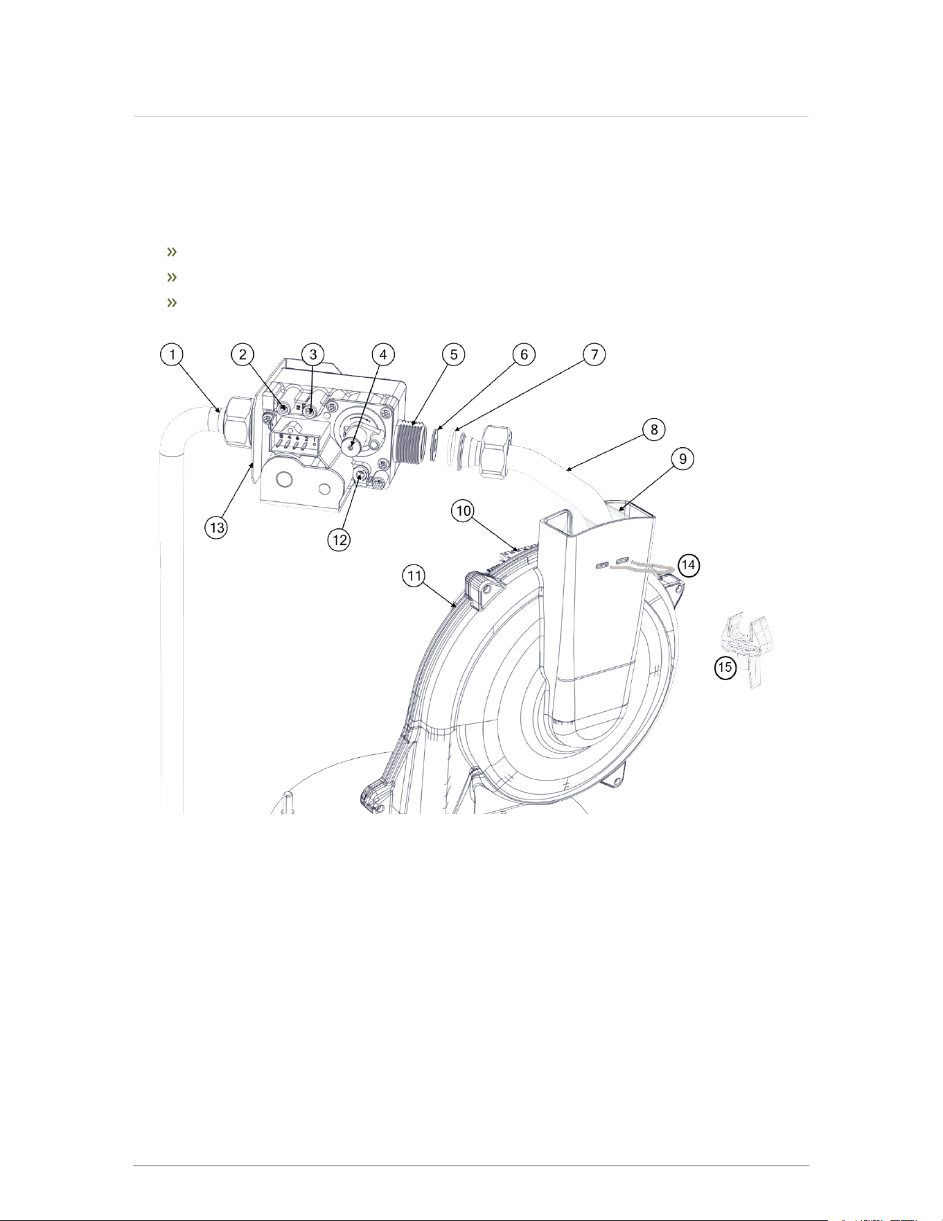
8.5 Replacing the fan, gas valve, and burner
This section documents the following maintenance procedures:
Replacing the fan
Replacing the gas valve
Replacing the burner.
Figure 48 Gas valve and fan components
72
Section: Service and maintenance
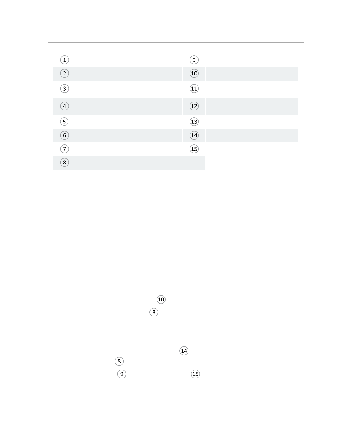
Gas valve inlet Fan inlet
Inlet gas pressure test port Fan plug
Manifold gas pressure test port
(not for field use)
Fan
Low fire adjustment (offset
pressure)
High Fire Adjustment
Gas valve outlet Gas valve support bracket
Orifice Venturi insert clip
O-ring Venturi insert
Gas valve outlet pipe
8.5.1 Replacing the fan
1. Turn off the electric power and gas supply to the boiler.
2. Ensure the boiler cools down to the surrounding temperature. Do not drain the boiler unless
freezing conditions are expected during this procedure.
3. Remove the front cover, and then remove the four Torx 20 head screws on the top panel of
the boiler.
A ladder or step may be required to have a clear vertical view of the work area. Do not
attempt to reach from the front without a clear view, as damage to connectors, screws or
refractory may occur.
4. Undo the union nut at the gas valve outlet.
5. Carefully remove the O-ring and orifice for re-installation later.
6.
Remove the electrical connection to the fan.
7.
Move the gas valve outlet tube away from the gas valve.
8. To remove the fan, unscrew the two bolts at the base of the fan, and retain with the washers
and fan gasket.
9. Carefully lift and remove the fan from the boiler case.
10.
From the fan, remove the venturi insert clip (with a flathead screwdriver) and the gas
valve outlet tube . Retain for reassembly.
11.
From the fan inlet , remove the venturi insert .
12. Remove the fan gasket.
13. Position the fan gasket (supplied in kit) onto the new fan, so that the holes align.
73
8.5.1 Replacing the fan

14. Secure the new fan onto the heat exchanger lid with bolts and washers.
15. Ensure that the venturi insert is in place.
16. Insert the gas valve outlet pipe and venturi clip.
17. Reinstall the components in reverse order. Upon reassembly, ensure that all O-rings and
gaskets are correctly positioned.
18. Check for leaks at the gas valve outlet and at the connection point between the fan and
the heat exchanger lid.
8.5.2 Replacing the gas valve
1. Turn off the electric power and gas supply to the boiler.
2. Ensure that the boiler cools down to the surrounding temperature.
3. Remove the front cover, and then remove the four Torx 20 head screws on the top panel of
the boiler.
A ladder or step may be required to have a clear vertical view of the work area. Do not
attempt to reach from the front without a clear view, as damage to connectors, screws or
refractory may occur.
4.
Remove the electrical connection to the fan.
5.
Move the gas valve outlet tube away from the gas valve.
6. Unscrew the top union nut of the flexible pipe attached to the gas valve/ bracket. Retain the
gasket.
7. Push the flexible pipe to the side.
8. To remove the gas valve, undo the union nut at the gas valve outlet.
9. Carefully remove the O-ring and orifice for re-installation later.
10. Install the new gas valve, tightening the union nut on the gas valve outlet with the O-ring
and orifice in place.
11. Reinstall the components in reverse order. Upon reassembly, ensure that all O-rings and
gaskets are correctly positioned.
12. Before restoring the boiler to normal operation, check for leaks at the gas valve inlet .
13. With the boiler operating, check for leaks at the gas valve outlet.
14. Tune the gas valve. For instructions, see Adjusting the gas valve on page 60.
15. After removing test equipment, check test ports and replace door.
74
Section: Service and maintenance
8.5.3 Replacing the burner
Warning
The heat exchanger has a small amount of combustion chamber insulation (refractory),
which contains ceramic fibers.
When exposed to extremely high temperatures, the ceramic fibers that contain crystalline
silica can be converted into cristobalite, classified as a possible human carcinogen.
Avoid disturbing or damaging the refractory. If the refractory is damaged it must be
replaced following the directions below.
Avoid breathing and contact with skin and eyes and follow these precautions:
1. For conditions of frequent use or heavy exposure, respirator protection is required.
Refer to the “NIOSH Guide to the Selection and Use of Particulate Respirators
Certified under 42 CFR 84” for selection and use of respirators certified by NIOSH.
For the most current information, NIOSH can be contacted at 1-800-356-4676 or on
the web at www.cdc.gov/niosh.
2. Wear long sleeved, loose fitting clothing, gloves and eyes protection.
3. Assure adequate ventilation.
4. Wash with soap and water after contact.
5. Wash potentially contaminated clothes separately from other laundry and rinse
washing machine thoroughly.
6. Discard used insulation in an air tight plastic bag.
NIOSH stated first aid:
Eye contact - Irrigate and wash immediately.
Breathing - Provide fresh air.
1. Turn off the electric power and gas supply to the boiler.
2.
Remove the front cover, and then remove the boiler's top panel by removing the four Torx head
screws on the top panel of the boiler.
Warning
Wear a suitable protective mask to avoid ingesting particles from the refractory.
3. Remove the electrical connection from the gas valve.
4. Undo the union nut at the gas valve outlet.
5. Carefully remove the O-ring and orifice for re-installation later.
75
8.5.3 Replacing the burner
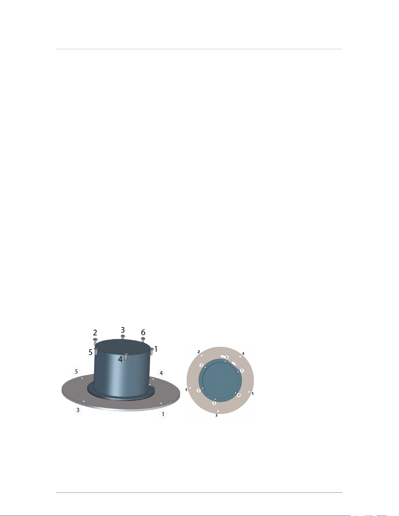
6. Remove the electrical connection to the fan.
7. For instructions on removing the fan, see Replacing the fan on page 73.
8. Remove the ignitor cables (green and red).
9. Remove the four (4) nuts securing the lid to the heat exchanger. The burner is attached to
the underside of the heat exchanger lid.
10. Carefully lift the lid upwards away from the studs. The gasket/refractory/burner should stay
with the lid as it is removed.
11. Remove the screws securing the ignitor, and then remove the ignitor and ignitor gasket.
12. Remove the refractory by sliding it over the burner.
13. Turn the heat exchanger lid over.
14. Remove the screws securing the burner to the heat exchanger lid, and remove the burner
and gasket. The burner gasket will likely be damaged during removal, and will need to be
replaced.
15. Install the new burner and gasket, ensuring that all screws are tightened evenly by
repeating the tightening sequence a few times as shown in the images below.
16. Reinstall the refractory. Carefully slide it over the burner all the way to the lid, ensuring that
the openings for the ignitor, view port and heat exchanger studs are aligned correctly.
17. Reinstall the ignitor gasket and ignitor with two screws.
18. Re-install the lid with burner and gasket/refractory assembly. Ensure that you tighten each
nut evenly by following the order indicated in the pattern below.
19. Re-install the remaining components in reverse order.
20. Turn on the electric power and gas supply to the boiler.
21. After firing the boiler, check for leaks at the gas valve inlet and at the connection between
the fan and the heat exchanger lid (if the fan was removed).
22. Check the gas valve tuning, and adjust as needed.
23. After removing test equipment, check test ports and replace door.
Figure 49 Order for tightening screws on burner and nuts on the lid
76
Section: Service and maintenance
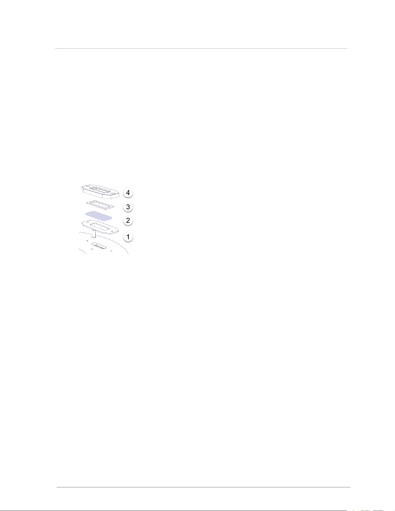
8.6 Cleaning the sight glass
When a new boiler is first fired up, gases in the system can cloud up the viewport. If so, you will need
to clean the sight glass to view the presence of a flame.
1. Turn off the electric power and gas supply to the boiler.
2. Remove the two screws holding the sight glass in place.
3. Remove the four components of the sight glass and wipe the glass clean.
4. Before you reassemble the sight glass, check that the gaskets are in good condition.
5.
Assemble the components (see image below), by first inserting the rubber gasket l inside
the refractory top m followed by the glass k, and then the graphite gasket j.
Figure 50 Four components of the sight glass
6. Replace onto the lid, and fasten with the two screws.
77
8.6 Cleaning the sight glass
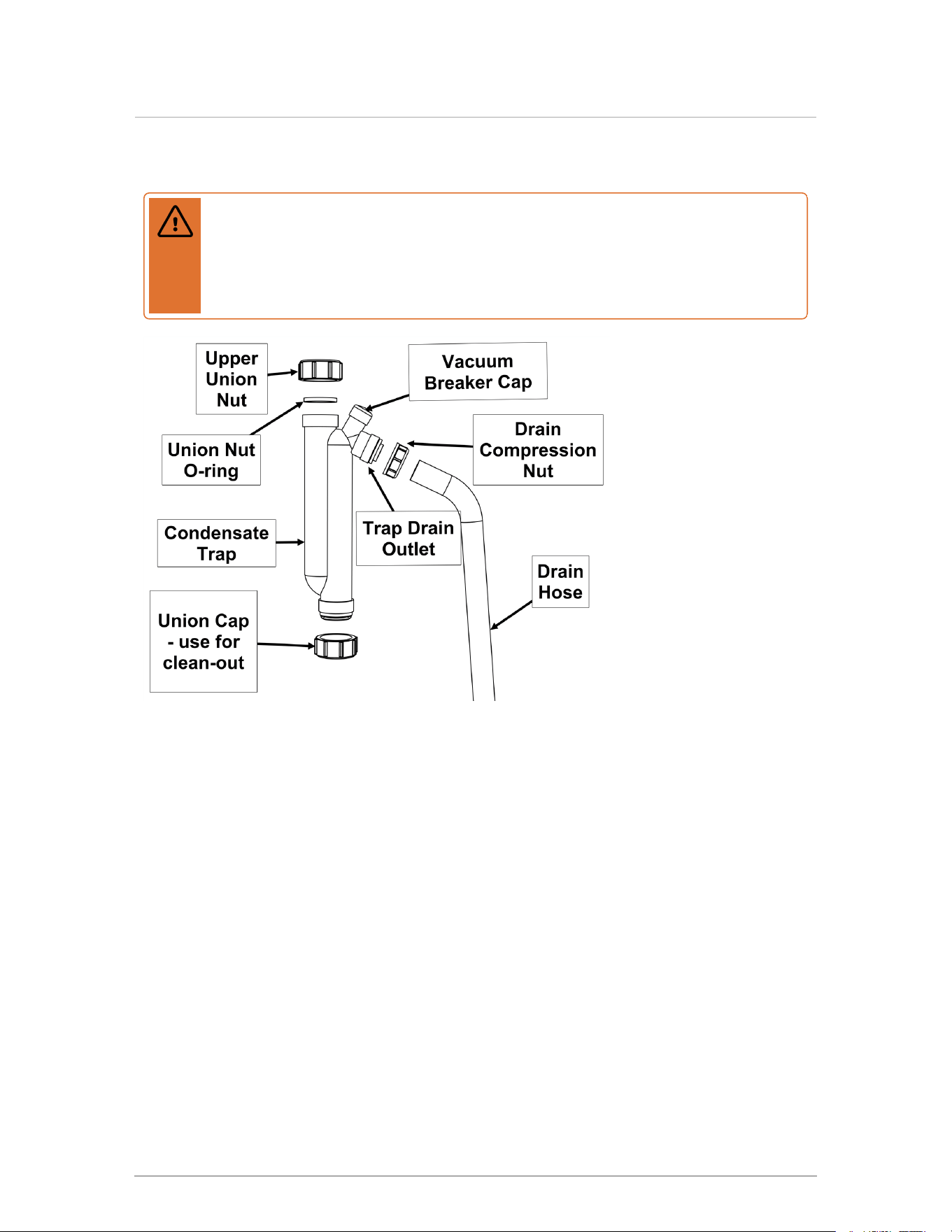
8.7 Cleaning the condensate trap
Warning
If condensate neutralization is used, check the pH level of condensate before and after
neutralization to verify effectiveness and ensure that the discharge has neutral pH
levels. Never operate the boiler unless the trap is filled with water. Failure to comply will
result in severe personal injury or death.
Condensate traps
should be checked
every year, cleaned
and refilled as
necessary. Before
cleaning the
condensate trap, you
must turn off the power
to the boiler, and allow
it to cool down.
Important: Installers or
service contractors
should ensure that the
end user is instructed
on cleaning and refilling
the trap.
For details, see Installing a condensate trap on page 34.
8.8 Ensure door in place
The boiler door must be in place during normal operation. Ensure door is in place after service.
78
Section: Service and maintenance
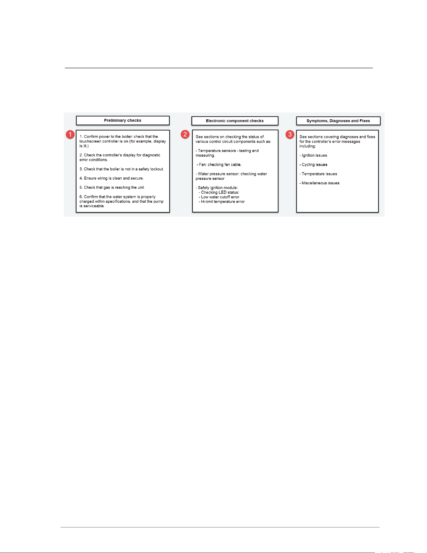
79
9.0 Troubleshooting
This section includes various conditions as well as possible solutions. Often, a problem can be
identified and solved through basic checks: confirming the electrical power supply, gas flow and
resetting the thermostat control. Below are some common troubleshooting issues including fixes.
9.1 Electronic components
This section details the method for troubleshooting the non-standard electronic components on the
boiler.
9.1.1 Temperature sensors
The resistance of the temperature sensors varies inversely with temperature. To test, measure the
temperature of the sensed environment and compare with the value derived from the measurement
of the resistance (obtained by connecting a good quality test meter capable of measuring up to 5,000
kΩ (5,000,000Ω) at the controller end of the sensor lead).
To obtain a resistance reading, remove power to the boiler. For the supply water, return water, and
vent temperature sensors, remove the wire leads by disconnecting their respective Molex
connectors. Place multi-meter probes into the sensor’s female Molex connector socket. Do not apply
voltage to the sensor as damage may result.
The supply water and vent temperature sensors each contain two separate circuits. Test each pair.
Both circuits must deliver accurate (although not necessarily identical) readings. Note that failures
may occur only within certain temperature ranges.

Temp. °F/°C
Resist.
Ω – Ohm
Temp. °F/°C
Resist.
Ω – Ohm
0 / -18 85,362 100 / 38 5,828
5 / -15 72,918 105 / 41 5,210
10 / -12 62,465 110 / 43 4,665
15 / -9 53,658 115 / 46 4,184
20 / -7 42,218 120 / 49 3,760
25 / -4 39,913 125 / 52 3,383
30 / -1 34,558 130 / 54 3,050
35 / 2 29,996 135 / 57 2,754
40 / 4 26,099 140 / 60 2,490
45 / 7 22,763 145 / 63 2,255
50 / 10 19,900 150 / 66 2,045
55 / 13 17,436 155 / 68 1,857
60 / 16 15,311 160 / 71 1,689
65 / 18 13,474 165 / 74 1,538
70 / 21 11,883 170 / 77 1,403
75 / 24 10,501 175 / 79 1,281
80 / 27 9,299 180 / 82 1,172
85 / 29 8,250 185 / 85 1,073
90 / 32 7,334 190 / 88 983
95 / 35 6,532 195 / 91 903
Table 15 Temperature sensor resistance values - 10K ohms
9.1.2 Fan
The fan is controlled via the SIM+ control. The SIM+ provides electronic commutating power to
the fan motor coilers determining the fan speed and power usage.
9.1.3 Water pressure sensor
The water pressure sensor ensures that there is adequate pressure in the heating system for
safe operation. The pressure is displayed in PSI as the default. If the system pressure should
drop below 8PSI the firing rate of the boiler is reduced. If the pressure drops to 4PSI or lower, the
boiler will not fire.
80
Section: Troubleshooting

Check the operation of the sensor by isolating the boiler from its system piping, and close the system
fill valve, and then crack the pressure relief valve. The pressure displayed should reflect declining
pressure. If it remains “fixed”, drain the boiler and replace the sensor, or dislodge any blocking debris
from the sensor inlet channel and reinsert.
9.1.4 Safety and Ignition Module (SIM+)
The SIM+ is a safety control, certified to conform to the UL 60730-5-5 and ANSI Z21.20-2014 •
CAN/CSA-C22.2 No. 60730-2-5-14 standards.
The module controls the boiler’s combustion fan, gas valve, sensors, safety and ignition functions
including:
Direct spark automatic ignition
Flame detection and current measurement
Supply water temperature sensing
Flue gas temperature sensing
Supply water maximum temperature shutdown
Flue gas maximum temperature shutdown
Low water cut-off.
The SIM+ continuously communicates with the boiler’s main controller reporting sensor readings
and status. The sensor readings and error status, if any are displayed on the boiler controller’s
screen.
81
9.1.4 Safety and Ignition Module (SIM+)
Table showing LED operating status
Its two status LEDs indicate the operating status as shown in the table below.
SIM Status Indicators
LED 1 LED 2 State
Description, LED status
indication
Rapid flash
Power up or
resetting
startup checks and initialization
Off Off Standby
LED 1 Off = No flame or sparking
LED 2 = Burner-on call state
Off On
Pre-purge or
inter-purge
LED 1 Off =No flame or sparking
LED 2 = Burner-on call state
On On Heating
LED 1 On = Flame detected
LED 2 = Burner-on call state
Rapid flash On Igniting
LED 1 Flashing - Electrode sparking
LED 2 = Burner-on call state
Off Flashing Lockout
Possible errors:
An operating limit was
exceeded
A sequence failed
An external sensor fault was
detected.
Flash alternately
with LED 2
Flash alternately
with LED 1
Fail-safe
An error was detected - the boiler
requires a power cycle
Table 16 SIM+ LED status Indicators
9.1.4.1 Resetting a boiler after a LWCO lockout
A boiler in a lockout condition due to a LWCO error will need to be reset.
1.
Go to > Clear Errors > Yes.
2. Check that there is enough water in the system and that the boiler is pressurized.
3.
To reset the boiler, go to > SIM Menu> LWCO Test > Reset > Yes.
4. Run the boiler to ensure that the error has been cleared.
5.
If the error persists, perform a LWCO test. Go to > SIM Menu> Hi-Limit Test > Run
the test to check if the low water cutoff sensor is opening.
82
Section: Troubleshooting
9.1.4.2 Resetting a boiler after a hi-limit temperature lockout
A boiler in a lockout condition due to a hi-limit temperature error will need to be reset.
1.
Go to > Clear Errors > Yes.
2. Check that there is no air trapped in the system and that the boiler is pressurized.
3.
To reset the SIM Module, go to > SIM Menu> Hi-Limit Test > Reset > Yes.
4. Run the boiler to ensure that the error has been cleared.
5.
If the error persists, perform a hi-limit test. Go to > SIM Menu> Hi-Limit Test > Run the
test to see if the hi-limit switch is operational. You can also perform this test for gasket
blowouts.
9.2 Troubleshooting error messages
The bottom line of the touchscreen displays the boiler's error status. The following colors represent
the boiler's operating status:
Green – Normal
Yellow – Warning
Red – Alarm
Errors shown on the touchscreen controller are described below as well as diagnoses and fixes. The
text inside the bar will indicate the specific warning or alarm. If there is more than one alarm present
the text will scroll slowly through all current alarm conditions. Besides the errors listed below, see
also Miscellaneous touchscreen controller errors on page 85.
83
9.2 Troubleshooting error messages

9.2.1 Ignition trials exceeded error
Ignition Trials Exceeded Error
Issue Diagnosis Fix
Error – Ignition trials
exceeded. Ignition
Failure after 3 tries
boiler has failed to
ignite on 3 successive
attempts. Boiler is in
lockout for 1 hour,
then repeats 3-try
sequence. Consult
service technician if
error recurs.
No spark • Check that ignition lead is secure
at the control module and at the
probe.
• Adjust ignition probe rod gap
between ⅛ and 3/16th inch (3.2-4.7
mm).
Gas line not fully purged, or
manual shutoff closed.
Purge gas lines. Check for gas flow.
Open manual gas shutoff and reset
boiler.
Boiler ignites, but shuts off at
the end of the ignition trial.
Improperly grounded pressure
vessel/burner or unserviceable
ignition lead or spark module.
Ensure the pressure vessel is
grounded. Check the ignition
probe/flame sensor is electrically
isolated from the vessel, and its
ceramic insulator is intact. Replace
ignition lead. Replace spark
module.
9.2.2 Water High Limit error
Water High Limit Error
Issue Diagnosis Fix
Error –
Water
High-Limit
Water temperature exceeds 208°F, or
201°F for 15 sec. Boiler is in hard lockout
mode.
See Resetting a boiler after a hi-
limit temperature lockout on page
83.
9.2.3 Low Water Cut-off error
Low Water Cutoff Error
Issue Diagnosis Fix
Error - Low
Water Cutoff
The Safety and Ignition module has
detected a low water condition.
See Resetting a boiler after a
LWCO lockout on page 82.
84
Section: Troubleshooting

9.2.4 Interlock 1 or 2 error
Interlock 1 or 2 error
Issue Diagnosis Fix
Error:Interlock [1 or
2] Open
Jumper lead on Interlock terminals of TP2 is
loose or compromised.
Replace the jumper
lead.
External safety is in an alarm state. Inspect the external
safety devices.
9.2.5 Vent High Limit
Vent High Limit
Issue Diagnosis Fix
Error:
Vent
High
Limit
• Venting material set to CPVC or Polypropylene (PP): exhaust gas
temperature exceeds 248°F for 6 seconds, or 232°F for 60 sec. Boiler
is in hard lockout mode.
• Venting material set to PVC:exhaust gas temperature exceeds
205°F for 6 seconds, or 189°F for 60 sec. Boiler is in hard lockout
mode.
• Check return
water
temperature.
9.3 Miscellaneous touchscreen controller errors
Miscellaneous errors
Issue Diagnosis Fix
Error - Max. delta
T Exceeded
• Outlet is more than 45°F
(25°C) above the inlet
temperature.
• Outlet is rising faster than 9°F
(5°C) per minute
• Check water flow.
• Check temperature sensor.
• Check wiring to temp sensor and control
module.
Error - LowRPM/
Air Flow
Fan is below 1150 RPM at the
end of fan pre-purge, or below
100 RPMduring heating.
• Check for blocked vent
• Check fan wiring connections
Error - Fan
Pressure
Exceeded SIM+fan power
threshold
• Check for blocked vent
Error - Module
High Current
Exceeded 24 VAC to SIM+ and
gas valve
• Check transformer output
Error - Low
Module Current
Inadequate current to gas valve
(starts below 25mA or stays
below 20mA)
• Inspect harness and ignition cable
• Inspect Interlock 1 & 2 external safety
circuits for excessive resistance
85
9.2.4 Interlock 1 or 2 error
Miscellaneous errors
Issue Diagnosis Fix
• Verify good supply voltage and ground
• On SIM+ check for constant 24V
between J2 harness terminals 1 (Red) & 7
(Blue)
• On SIM+ check for 24V during a trial for
ignition between J2 harness terminals 2
(Orange) & 7 (Blue)
Error - Low Water
Pressure
Inlet water pressure below 4 psi • Check system for leaks
• Check water pressure, expansion tank
• Check pressure sensor connection
Error - Inlet Pres.
Sensor
Inlet water pressure sensor
appears to be shorted or
disconnected.
• Check wiring to sensor
• Replace sensor.
Error -
See:Status > SIM
menu > Status
SIM/SIM+ has detected an error
that has subsequently cleared
• Note error in log
• Restart to observe operation
Error - Roll Out
Switch
Rollout switch, by combustion
chamber, has detected 230°F
temperature.
• Inspect lid, fan and ignitor gaskets
• Manually reset when safe
Error - Controller
Board
Error internal to control board • Typically result of poor incoming power
• May require a reboot
Error - No
Boilernet Comm
Controller set as Master cannot
detect at least one other board
• Check Subordinate boiler is on
• Check network wiring
• Check IPNetwork numbers
Error - No
MACaddress
Boiler cannot verify a valid
MACaddress
• See Network Settings
Error - Flame
Signal / Vent
Block
SIM+flame current drops below
minimum values shown here:
Flame Current Minimums
Model
≤ 3500
RPM
3500
RPM
110 2.8 μA 2.3 μA
150 3.4 μA 2.9 μA
199 4.8 μA 4.0 μA
• Check for vent blockage
• Check for poor gas pressure
• Check for unstable flame or improper
combustion CO
2
%
• Check condition and grounding of flame
rod
Error - Reversed
Flow
Return temperature reads
higher than supply temperature
for 10 minutes
• Check boiler pump flow direction
• Check wiring connections for supply and
return sensors
86
Section: Troubleshooting
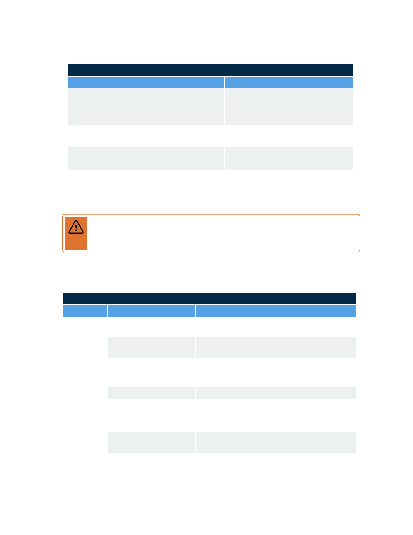
Miscellaneous errors
Issue Diagnosis Fix
Error - Temp.
probe error
An internal temperature sensor
appears to be shorted or open
circuit.
• Check supply, return and vent
temperature sensors
• Error will trigger if above dual sensors
deliver divergent values
Error - Unhandled
error code
Reserved for unforeseen
conditions
Contact Tech Support
Blank – screen
dark
• Check transformer; replace if damaged.
• Check circuit board for visible damage.
Controller is stuck
in "service" mode
after software
update.
If update fails or no updates
applied.
• Restarting returns the boiler to normal
operation.
Warning
Never attempt to repair the control module (circuit board). If the control module is
defective, replace it immediately.
9.3.1 Ignition issues
Ignition issues
Issue Diagnosis Fix
Noisy spark
when igniting
Ignition lead is not firmly
connected.
Reconnect ignition lead.
Contaminants/moisture on
igniter probe/flame sensor.
Ensure probe is dry by re-running post-purge;
otherwise, clean or replace igniter probe.
Boiler
rumbles
when
igniting.
Fluctuating gas pressure/
gas pressure too high/too
low.
Check CO
2
level via analyzer.
Check for proper gas piping Check pressure with manometer during ignition.
Boiler will not
attempt to
ignite. Fan
and pump
are operating
normally.
No power to ignition control
module.
Check system wiring.
Check air reference tubing.
Igniter probe/flame sensor
disconnected.
Reconnect probe.
Defective Control Module. Check ignition output from control module.
87
9.3.1 Ignition issues

Ignition issues
Issue Diagnosis Fix
Boiler will not
attempt to
ignite. Fan
and / or pump
are off.
Display not
illuminated
No power to boiler. Check line voltage.
Defective transformer. Check transformer. Reconnect or replace as needed.
9.3.2 Temperature issues
Temperature issues
Issue Diagnosis Fix
Low heat Operating
temperature too low.
Increase temperature target.
Priority parameters or
load configuration
improperly set up.
Review load configuration parameters.
appliance undersized. Refer to Load Calculation vs. Boiler Output.
Air trapped within
system.
Bleed system as required.
Improper system
piping.
Refer to recommended piping guidelines for the
respective boiler model.
System pump
undersized.
Check pump manufacturer’s data/check temp
differential across heat exchanger.
Poor gas:air mixing. Check CO
2
level.
Defective thermostat. Refer to manufacturer’s instructions.
Obstruction in
condensate drain.
Inspect and clean condensate drain.
appliance cycling on
operating/ safety
controls.
Check operation with Ohmmeter/Voltmeter.
System radiation
undersized.
Check manufacturer’s rating tables for capacity per
foot.
Temperature
exceeds
thermostat
setting
Incorrect anticipator
setting.
Check with Ammeter if connected to zone value; if to
boiler, set to zero
Mercury thermostat
not level.
Check level.
88
Section: Troubleshooting

Temperature issues
Issue Diagnosis Fix
One or more
zones do not
heat properly
Air trapped within
zone(s) piping
Vent system/zone as required.
Low radiation/
excessive heat loss.
Check actual length of pipe using radiation / heat loss
calculation.
Low flow rate to zone
(s).
Check temperature drop across zone.
Defective zone valve/
zone circulator.
Check operation per manufacturer’s instructions.
9.3.3 Miscellaneous issues
Miscellaneous issues
Issue Diagnosis Fix
Fumes and
High
Humidity
Improperly installed
condensate trap
Refer to installation/operation instructions.
Leak in vent piping Inspect using soap solution.
Flue gas leak within
boiler
Visually inspect all mechanical connections.
‘Ghost’ call
for heat.
Triac or ‘Power-
robbing’ thermostat
sending current to
boiler.
Remove Therm. connections from boiler to confirm that
stray voltage, or current induced in thermostat wiring, is
source of nuisance signal. Replace the Power Robbing
thermostat, isolate the thermostat with a relay or install a
properly sized resistor.
Error: Water
High Limit /
Low Water
Cutoff won’t
clear.
Boiler is in 1-hour
safety lockout.
For instructions on clearing errors, see Resetting a boiler
after a hi-limit temperature lockout on page 83 and
Resetting a boiler after a LWCO lockout on page 82.
DHW taking
too long to
heat.
Sensor may be under-
reading actual water
temp.
Check sensor engagement; note well is 15 cm / almost 6
inches deep and sensor must be fully set to back. Check
programmed settings boiler temp set too close to the
required DHW temperature.
89
9.3.3 Miscellaneous issues

Miscellaneous issues
Issue Diagnosis Fix
Boiler output
not
modulating
up to
maximum
despite target
not being
reached.
Possible flow issue:
check for 35 or 40 °F
temperature difference
between boiler supply
and return water
temperatures (evokes
electronic fence).
Confirm that primary pump is able to overcome head loss
of boiler and primary loop piping at the required flow rate.
Primary
Pump runs
but load
pumps do
not.
Wiring not complete. Supply power to the PV/L and PV/N terminals from the
incoming power supply to the boiler. (Factory wired on
boilers with a factory installed touchscreen controller)
9.3.4 Cycling issues
Short-Cycling Issues
Diagnosis Fix
Improper values entered via
keypad.
Check load maximum temps are above target temps, by ½ of
the selected boiler differential. Ensure boiler differential is OK
(16 - 30 °F is generally adequate)
Excess condensate in venting. Check venting slopes on horizontal runs. Look for sags.
Obstruction in condensate trap. Inspect and clean condensate trap.
Improper vent length or
improper slope to vent.
Check venting. Compare vent length and diameter.
Incorrect settings or defective
thermostat.
Check operation. Refer to manufacturer’s instructions. Check
setting with ammeter.
Air in system or marginal water
flow.
Bleed/purge system as required. Confirm adequate pump
size and temp rise in the heat exchanger.
Slow combustion air blower. Check that CO
2
level is within specification.
Dirty burner/heat exchanger. Check pressure drop.
Low water flow due to improper
piping.
Refer to recommended piping for the respective boiler model.
Low water flow due to
undersized pump.
Check manufacturer’s rating charts/check temperature
differential across heat exchanger.
Low water flow due to
restrictions in water pipe.
Check temperature differential across zone/heat exchanger.
90
Section: Troubleshooting

Short-Cycling Issues
Diagnosis Fix
Low radiation. Check actual amount of radiation per zone and refer to
manufacturer’s rating tables.
Appliance over-fired. Clock gas meter/check gas pressure with manometer/ check
CO
2
level.
Appliance Oversized. Check load calculation vs. minimum boiler output.
Improperly set or defective
controls.
Check operation with ohmmeter/voltmeter.
91
9.3.4 Cycling issues

Intentionally left empty
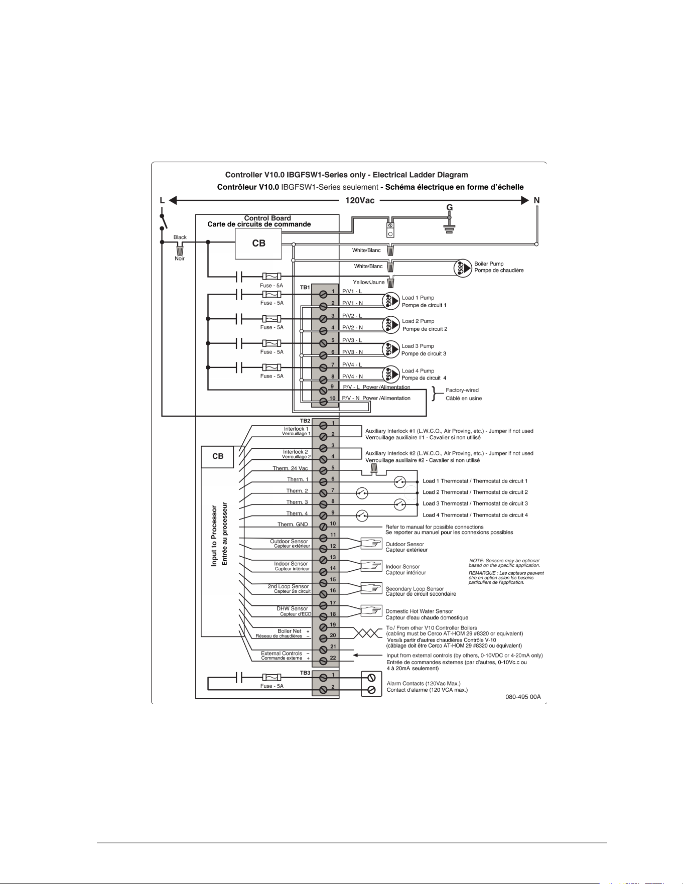
93
Appendices
Wiring diagrams
Figure 51 Controller electrical diagram
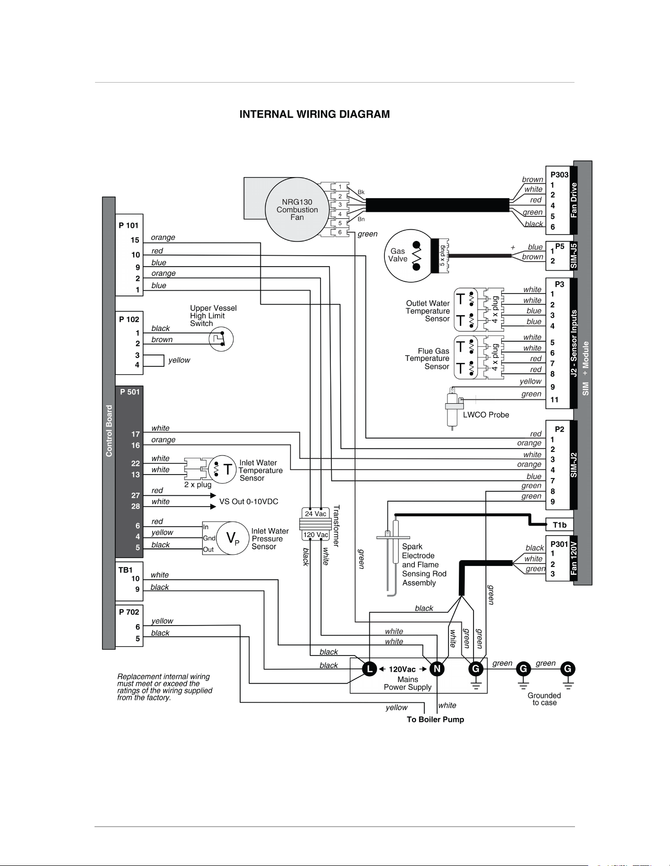
Figure 52 Boiler internal wiring diagram
94
Section: Appendices
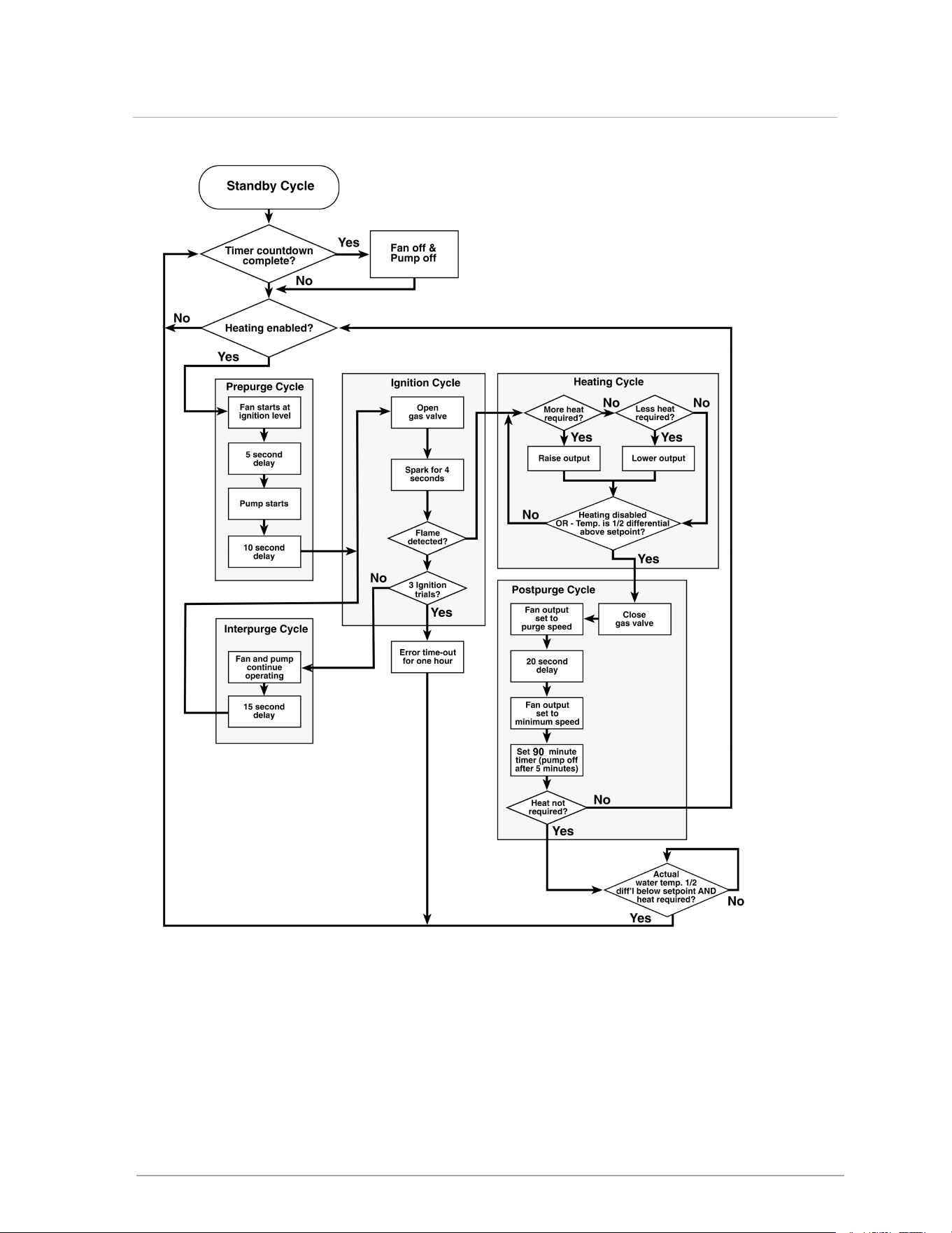
Figure 53 Sequence of Operation
95
Appendices
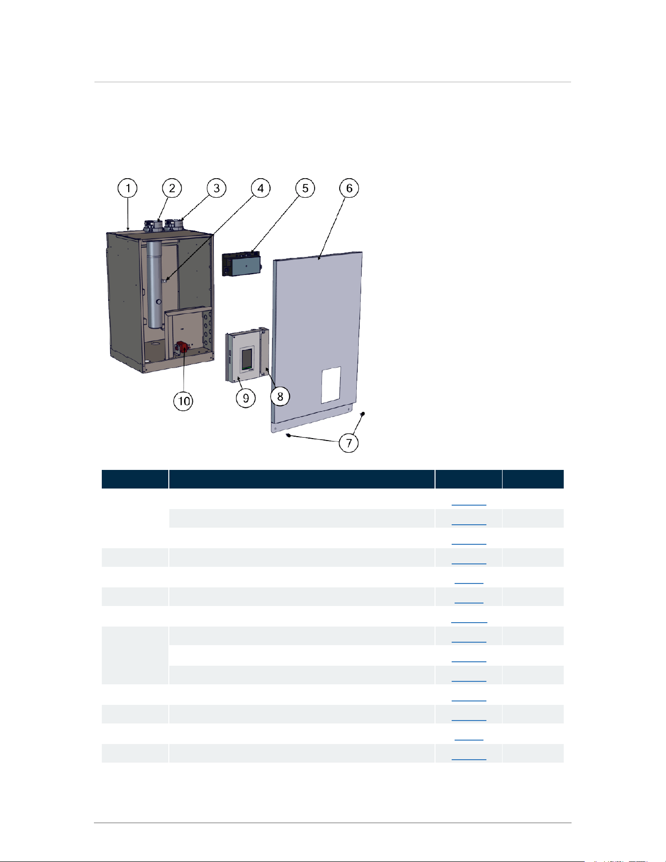
Part diagrams - Boiler Model 110, Boiler Model
150, Boiler Model 199
Item ID Description P-kit # Qty
1
Top access cover - Boiler Model 110
P-1506 1
Top access cover - Boiler Model 150
P-1531 1
Top access cover - Boiler Model 199
P-1532 1
2 Exhaust duct P-1507 1
3 Intake duct P-391 1
4 High limit temperature sensor P-361 1
5 Safety Ignition Module plus (SIM+) P-271B 1
6
Front door cover - Boiler Model 110
P-1508 1
Front door cover - Boiler Model 150
P-1533 1
Front door cover - Boiler Model 199
P-1534 1
7 Thumb screw (in hardware kit) P-1541 2
8 Terminal block cover P-1509 1
9 V-10 touchscreen controller P-242 1
10 Transformer P-9059 1
96
Section: Appendices
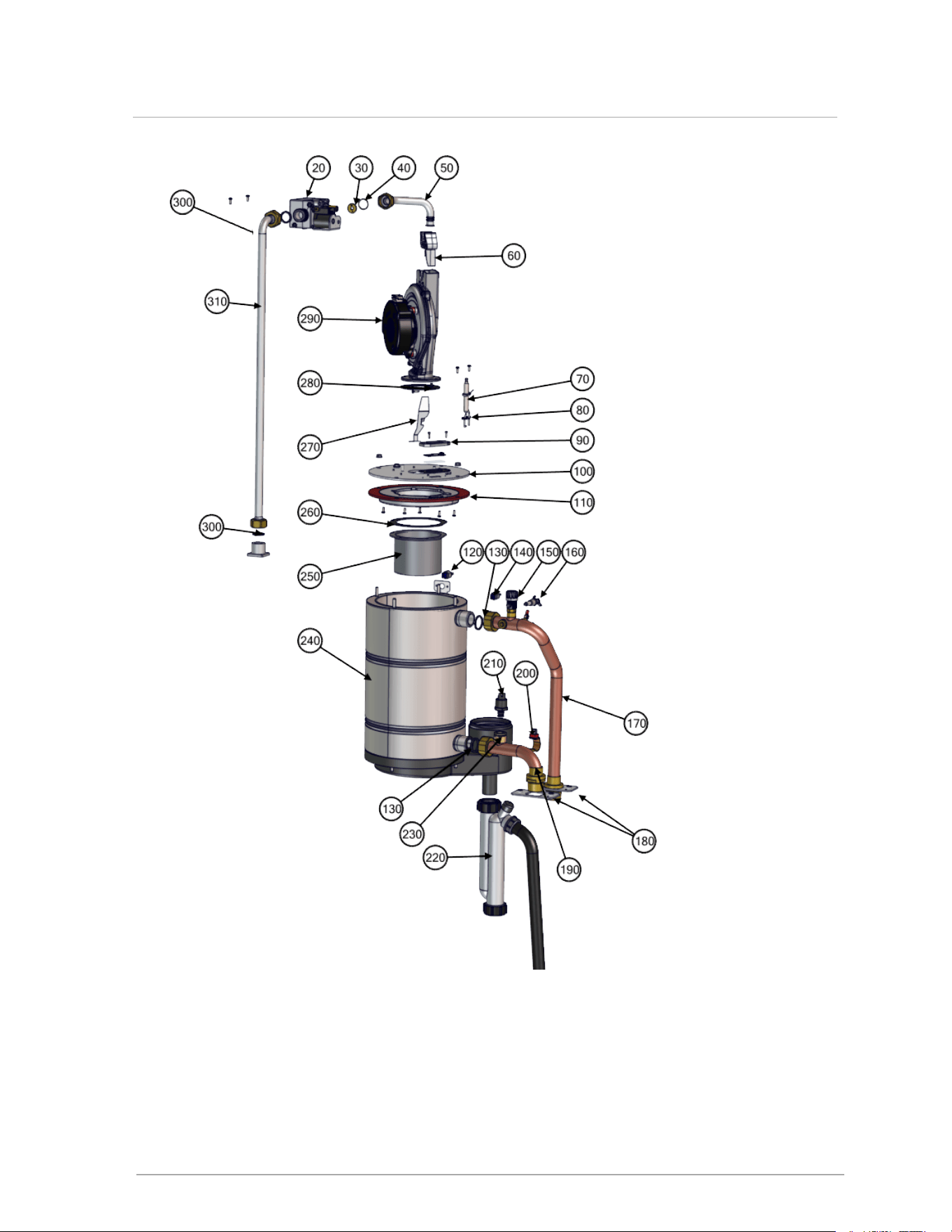
97
Part diagrams - Boiler Model 110, Boiler Model 150, Boiler Model 199
Item ID Description
P-kit
replacement
#
Quantity
20 Gas valve P-326B 1
30
Orifice NG 505
P-1501
1
Orifice LP 410
P-1500
1
Orifice NG 620
P-1503
1
Orifice LP 520
P-1502
1
Orifice NG 705
P-1505
1
Orifice LP 580
P-1504
1
40 O-ring, gas valve outlet (in gasket pack) P-1522 1
50 Gas valve outlet pipe P-1510 1
60
Venturi insert - Boiler Model 110 (NRG 130) 50 mm
P-821 1
Venturi insert - Boiler Model 150 (NRG 130) 43.5 mm
P-338 1
Venturi insert - Boiler Model 199 (NRG 130) 37.5 mm
P-336
1
70 Ignitor and 2 screws P-1511 1
80 Ignitor gasket (pack of 5) P-117 1
90 Sight glass and 2 screws P-107A 1
100
Heat exchanger lid - Boiler Model 110
P-1512 1
Heat exchanger lid - Boiler Model 150
P-1524 1
Heat exchanger lid - Boiler Model 199
P-1528 1
110
Refractory and gasket - Boiler Model 110
P-1513 1
Refractory and gasket - Boiler Model 150
P-1525 1
Refractory and gasket - Boiler Model 199
P-1529 1
120 Rollout switch P-9070 1
130 Gasket, supply/ return pipe union P-9235 2
140 Supply temperature sensor P-362 1
150 Manual air vent P-1219 1
160 Low water cutoff (behind supply pipe) P-9061 1
170 Supply water pipe P-1514 1
180 Supply / return water pipe bracket P-1515 2
190 Return water pipe P-1516 1
200 Return water temperature sensor P-1011 1
210 Water pressure sensor P-1517 1
98
Section: Appendices
Item ID Description
P-kit
replacement
#
Quantity
220 Condensate trap P-115 1
230 Water pressure sensor clip (sold with sensor) P-1517 1
240
Heat exchanger - Boiler Model 110
P-1518 1
Heat exchanger - Boiler Model 150
P-1523 1
Heat exchanger - Boiler Model 199
P-1527 1
250
Burner 110 P-1519 1
Burner 150 P-1526 1
Burner 199 P-1530 1
260
Burner gasket Boiler Model 110 (in gasket pack)
P-1522 1
Burner gasket Boiler Model 150 & Boiler Model 199 (in
gasket pack)
P-1522 1
270 Fan insert P-1520 1
280 Fan gasket P-1520 1
290 Fan P-1520 1
300 Inlet gas line union gasket (in gasket pack) P-1522 2
310 Gas line P-1521 1
99
Part diagrams - Boiler Model 110, Boiler Model 150, Boiler Model 199

Intentionally left empty

101
Installation and Commission Report
Model Number Serial Number
Date of Installation
User contact information Installer Information Company
Fuel (select type) Gas Supply Pressure Measured Rate of Input
Natural Gas Propane Gas
(high fire)Inches w.c. (high fire)Btu/hr
Leak testing completed
Gas Piping Venting System Fan
Combustion Components
System Cleaned and Flushed
System Filled
Type of Cleaner Used Glycol/ chemicals used?Type/ concentration
Ignition Safety Shutoff test completed
Flame Current Reading
High Fire µA
Low fire µA
Air purge completed
Relief Valve Condensate trap
Correctly
installed and
piped
Relief valve “try
lever” test
performed
Filled
Drain
clear and
free
flowing
Condensate
Neutralization?
Combustion Readings: CO
2
% CO ppm Flue temperature Return water temperature
High Fire
Low Fire
measure simultaneously
Commissioning has been completed as listed on this report
Owner advised and instructed in the safe operation and maintenance of the boiler and
system.
Information regarding the appliance and installation received and left with owner.
Installer Signature :
Yes No
102
Section: Appendices

The following message is relevant to users in the USA:
Important
This Boiler is equipped with a feature that saves energy by reducing the boiler water
temperature as the heating load decreases. This feature is equipped with an override
which is provided primarily to permit the use of an external energy management system
that serves the same function.
THIS OVERRIDE MUST NOT BE USED UNLESS AT LEAST ONE OF THE
FOLLOWING CONDITIONS IS TRUE:
• An external energy management system is installed that reduces the boiler water
temperature as the heating load decreases.
• This boiler is not used for any space heating.
• This boiler is part of a modular or multiple boiler system having a total input of
300,000 BTU/hr or greater.
• This boiler is equipped with a tankless coil.
US installers should contact their distributor for any further information required.

May 02, 2025 | 120-619E0
©2025
Information in this document is subject to change without notice. The distributor assumes no responsibility for changes
made to the manual due to clerical errors, to regulation changes, or to product development.