GRID
™
20
INSTALLATION INSTRUCTIONS
Important Safety Information
WARNING
See the Important Safety and Product Information guide in the product box for product warnings and other
important information.
When connecting the power cable, do not remove the in-line fuse holder. To prevent the possibility of personal
injury or product damage caused by fire or overheating, the appropriate fuse must be in place as indicated in
the product specifications. Connecting the power cable without the appropriate fuse in place voids the product
warranty.
Failure to install this device according to these instructions could result in personal injury, damage to the vessel
or device, or poor product performance.
CAUTION
To avoid possible personal injury, always wear safety goggles, ear protection, and a dust mask when drilling,
cutting, or sanding.
To avoid possible personal injury or damage to the device and vessel, disconnect the vessel's power supply
before beginning to install the device.
To avoid possible personal injury or damage to the device or vessel, before applying power to the device, make
sure that it has been properly grounded, following the instructions in the guide.
To avoid possible personal injury or damage to this device and vessel, only install this device when the vessel is
on land, or when properly secured and docked in calm water conditions.
NOTICE
When drilling or cutting, always check what is on the opposite side of the surface to avoid damaging the vessel.
Read all installation instructions before proceeding with the installation. If you experience difficulty during the
installation, contact Garmin
®
Product Support.
Software Update
You must update the Garmin chartplotter software when you install this device. For instructions on updating the
software, see your chartplotter owner's manual at support.garmin.com.
GUID-36F2BF7D-574E-4423-B70B-BE3EB05AC4CD
v4
February 2025
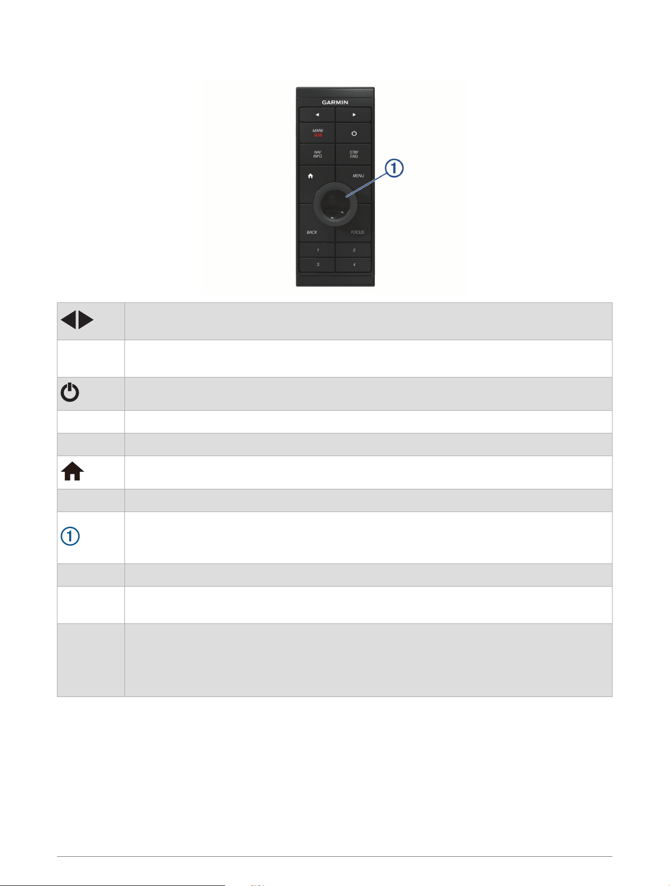
Keys
Hold both keys to begin pairing.
Press to move between displays in the station.
MARK SOS
Press to save the present location as a waypoint.
Hold for one second to mark an SOS location and begin a route back to the location.
Press repeatedly to scroll through the backlight brightness levels.
NAV INFO Press to display navigation information, such as points of interest, user data, and graphs.
STBY ENG Press to engage the autopilot or put it in standby mode.
Press to return to the home screen.
MENU Press to open or close additional settings about that screen.
Spin or tilt to move the cursor or highlight.
Spin to zoom in or out of a view.
Press to make a selection.
BACK Press to return to the previous screen.
FOCUS
Press to move a highlight to a different section of the screen.
Press to move a highlight to a different function or window on a combination screen.
1 2 3 4
Hold to assign a shortcut key to the active screen.
NOTE: If necessary, use the FOCUS key to highlight the active screen.
TIP: You can also assign a shortcut to a highlighted home screen icon.
Press to open the assigned screen.
2

Tools Needed
• Drill and drill bits
◦ 3mm (
1
/
8
in.) drill bit
◦ 13mm (
1
/
2
in.) drill bit
◦ 2mm (
1
/
4
in.) drill bit for wood screws
◦ 4mm (
3
/
16
in.) drill bit for the nut plates
◦ 5mm (
3
/
16
in.) drill bit for the nut plates
• #2 Phillips screwdriver
• Jigsaw or rotary tool
• File and sandpaper
• Marine-grade sealant, approved for use on plastics (recommended)
• Two AA alkaline, NiMH, or lithium batteries (if powering with batteries)
Mounting and Connection Considerations
NOTICE
This device should be mounted in a location that is not exposed to extreme temperatures or conditions. The
temperature range for this device is listed in the product specifications. Extended exposure to temperatures
exceeding the specified temperature range, in storage or operating conditions, may cause device failure.
Extreme-temperature-induced damage and related consequences are not covered by the warranty.
The mounting surface must be flat to avoid damaging the device when it is mounted.
The GRID 20 device requires a power connection and a data connection, using one of three methods:
• NMEA 2000
®
network for power and data
• Included power cable and an ANT
®
wireless connection
• AA batteries (not included) and an ANT wireless connection
This device can be mounted in a dashboard or other surface using the included hardware. When selecting a
mounting location, observe these considerations.
• To avoid interference with a magnetic compass, you must not mount the device closer to a compass than
11.4cm (4.5in.).
• You must mount the device in a location that allows room for the routing and connection of the NMEA 2000
cable, power cable, or the replacement of the batteries.
• The NMEA 2000 connection method can be used to remove all risk of issues caused by wireless interference
from other devices and in cases where there are wireless range concerns. The cables necessary to connect
to the NMEA 2000 network are not included.
• When connecting wirelessly, you must test the GRID 20 device's performance at the selected location before
mounting.
3

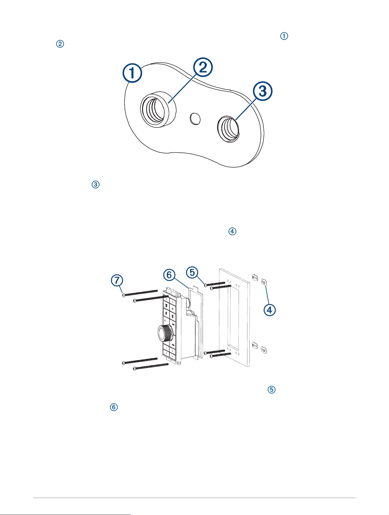
Mounting the Device
NOTICE
Use only the included hardware when mounting this device. Using mounting hardware not provided with the
device may damage the device.
Be careful when cutting the hole to flush mount the device. There is only a small amount of clearance between
the case and the mounting holes, and cutting the hole too large could compromise the stability of the device
after it is mounted.
If you are mounting the device on fiberglass with screws, it is recommended to use a countersink drill bit to drill
a clearance counterbore through only the top gel-coat layer. This will avoid cracking in the gel-coat layer when
the screws are tightened.
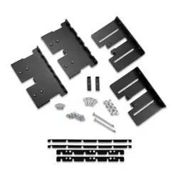
The included template and hardware can be used to flush mount the device at the selected location. There are
three options for hardware based on the mounting surface material.
• You can drill holes and use the included nut plates and machine screws. The nut plates can add stability to a
thinner surface and allow you to more easily remove the device when you need to change the batteries.
• You can drill pilot holes and use the included wood screws. You should only use wood screws if you are
connecting to power using the included cable or the NMEA 2000 network, or if you are using batteries and
have access to the back of the device to replace the batteries. Do not use wood screws if you are using
batteries and do not have access to the back of the device to replace the batteries.
• You can drill and tap holes, and use the included machine screws.
1 Trim the template and make sure it fits in the location where you want to mount the device.
2 Secure the template to the selected location.
3 Using a 3mm (
1
/
8
in.) drill bit, drill a hole in each corner of the solid line on the template.
4 Using a 13 mm (
1
/
2
in.) drill bit, drill one or more of the large holes indicated along the inside of the solid line
on the template to allow access for a jigsaw.
5 Using a jigsaw or rotary tool, cut the mounting surface along the inside of the solid line on the template.
6 Place the device in the cutout to test the fit.
7 If necessary, use a file and sandpaper to refine the size of the cutout.
8 After the device fits correctly in the cutout, ensure the mounting holes on the device line up with the larger,
outer holes on the template.
9 If the mounting holes on the device do not line up, mark the new hole locations.
10 Based on your mounting method, drill the larger, outer holes:
• Drill 5mm (
3
/
16
in.) holes for the included nut plate and machine screws.
• Drill 2mm (
5
/
64
in.) pilot holes for the included wood screws, and skip to step 16.
• Drill and tap M3.5 holes for the included machine screws, and skip to step 16.
4
11 If you are using a nut plate, starting in one corner of the template, place a nut plate over the larger, outer
hole drilled in the previous step.
The smaller hole on the nut plate should line up with the smaller hole on the template.
12 If the smaller hole on the nut plate does not line up with the smaller hole on the template, mark the new hole
location.
13 If you are using a nut plate, drill a 4mm (
3
/
16
in.) hole in the smaller hole location.
14 Remove the template from the mounting surface.
15 Starting in one corner of the mounting location, place a nut plate on the back of the mounting surface,
lining up the large and small holes.
The raised portion of the nut plate should fit into the larger hole.
16 Secure the nut plates to the mounting surface by fastening the shorter screws through the smaller, inner
hole.
17 Install the foam gasket on the back of the device.
The pieces of the foam gasket have adhesive on the back. Make sure you remove the protective liner before
installing them on the device.
18 If you will not have access to the back of the device after you mount it, connect the necessary cable or install
the AA batteries (observing polarity) as needed before placing the device into the cutout.
NOTE: To prevent corrosion of the metal contacts, if you are not using a cable, firmly press the weather cap
over the connector.
5
19 Apply marine sealant between the mounting surface and the device to properly seal and prevent leakage
behind the dashboard.
20 If you will have access to the back of the device, apply marine sealant around the cutout.
21 Place the device into the cutout.
22 Secure the device to the mounting surface using the longer machine screws or included wood screws,
depending on the mounting method.
23 Wipe away all excess marine sealant.
24 Install the trim caps by snapping them in place around the top and bottom of the device.
Connecting the GRID 20 Device
The GRID 20 device requires a power connection and a data connection, using one of three methods:
• NMEA 2000 network for power and data
• Included power cable and an ANT wireless connection (Pairing the GRID 20 Device with the Chartplotter,
page8)
• AA batteries (not included) and an ANT wireless connection (Pairing the GRID 20 Device with the Chartplotter,
page8)
NOTE: The NMEA 2000 connection method can be used to remove all risk of issues caused by wireless
interference from other devices and in cases where there are wireless range concerns. The cables necessary to
connect to the NMEA 2000 network are not included.
After you supply power to the GRID 20 device, you must pair it with the chartplotter to make the data connection
(Pairing the GRID 20 Device with the Chartplotter, page8).
NMEA 2000 Connection Considerations
NOTICE
If you are connecting to an existing NMEA 2000 network, identify the NMEA 2000 power cable. Only one NMEA
2000 power cable is required for the NMEA 2000 network to operate properly.
A NMEA 2000 Power Isolator (010-11580-00) should be used in installations where the existing NMEA 2000
network manufacturer is unknown.
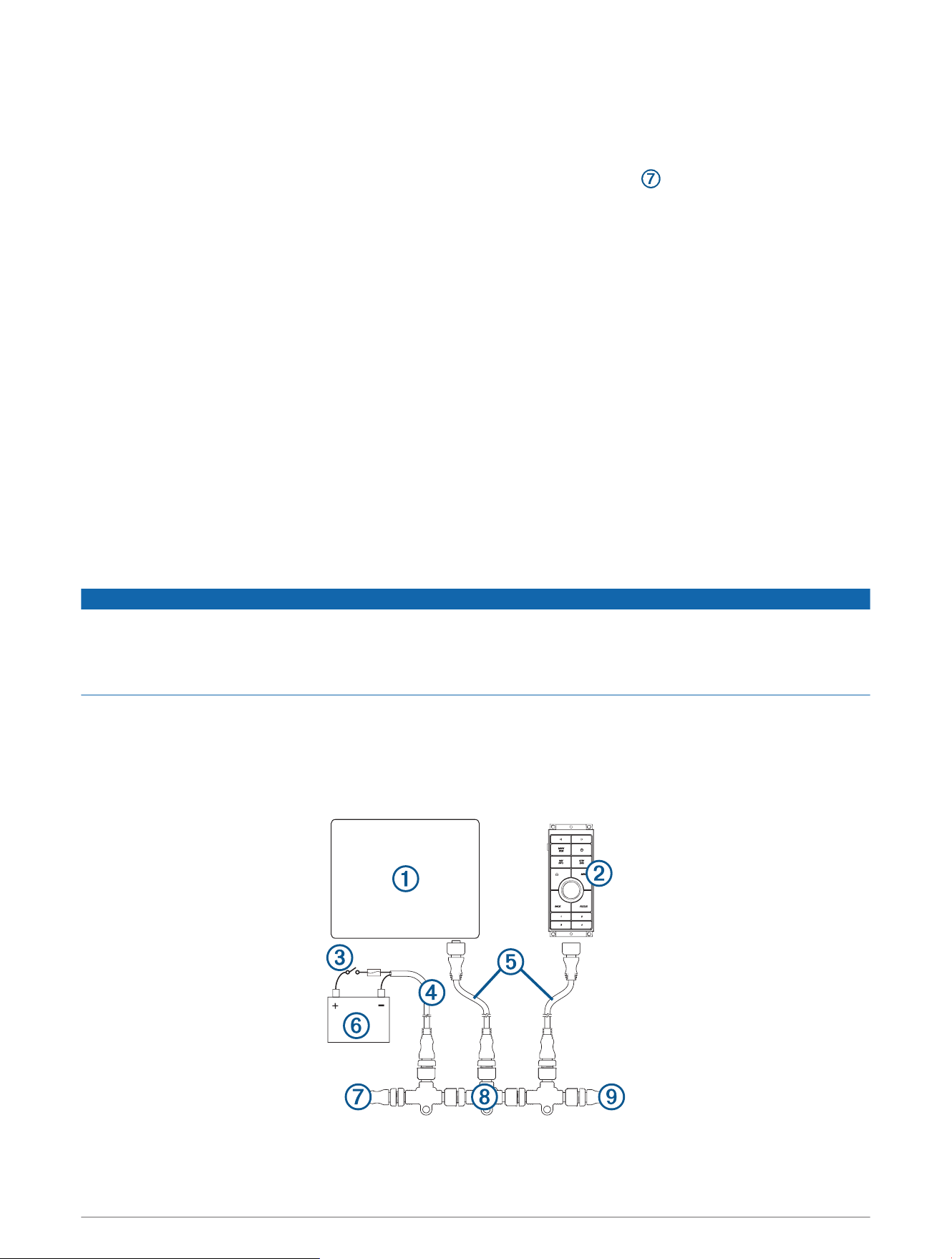
You can connect the GRID 20 device to a NMEA 2000 network on your boat to provide a power and data
connection. If you connect the GRID 20 device to a NMEA 2000 network, you do not need to use batteries, the
included power cable, or an ANT wireless connection.
If you need to create a NMEA 2000 network and are unfamiliar with it, go to support.garmin.com for more
information.
6
Compatible Garmin chartplotter
GRID 20
Ignition or in-line switch
NMEA 2000 power cable
NMEA 2000 drop cable
12Vdc power source
NMEA 2000 terminator or backbone cable
NMEA 2000 T-connector
NMEA 2000 terminator or backbone cable
After making the NMEA 2000 network connection, you must pair the GRID 20 device with the chartplotter
(Pairing the GRID 20 Device with the Chartplotter, page8).
Connecting to Power
WARNING
When connecting the power cable, do not remove the in-line fuse holder. To prevent the possibility of personal
injury or product damage caused by fire or overheating, the appropriate fuse must be in place as indicated in
the product specifications. Connecting the power cable without the appropriate fuse in place voids the product
warranty.
1 Route the power cable to the power source and to the device.
2 Connect the red wire to the positive (+) battery terminal, and connect the black wire to the negative (-) battery
terminal.
3 Connect the power cable to the device, and turn the locking ring clockwise to tighten it.
After connecting to power, you must pair the device with the chartplotter (Pairing the GRID 20 Device with the
Chartplotter, page8)
7
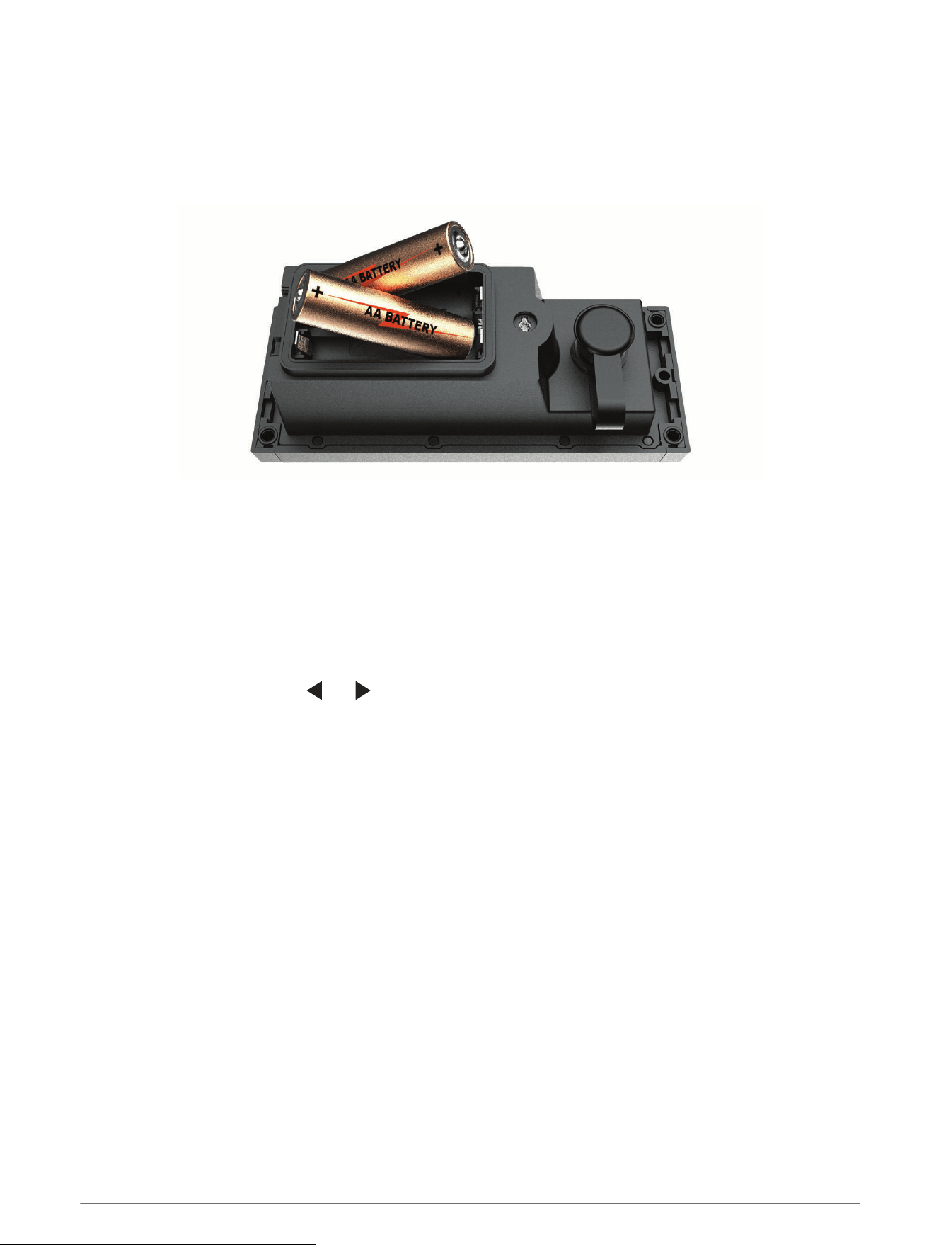
Installing the Batteries
You can use AA alkaline, NiMH, or lithium batteries (not included). Use lithium batteries for best results.
NOTE: Do not install batteries if you are using the included power cable or a NMEA 2000 network connection.
1 Turn the D-ring counter-clockwise, and pull up to open the battery door.
2 Insert two AA batteries, observing polarity.
NOTE: You should verify the gasket and battery compartment are free of debris.
3 Close the battery door, and turn the D-ring clockwise.
After installing batteries, you must pair the device with the chartplotter (Pairing the GRID 20 Device with the
Chartplotter, page8)
Pairing the GRID 20 Device with the Chartplotter
After you supply power to the GRID 20 device, you must pair it with the chartplotter to make the data
connection.
1 On the compatible chartplotter, select Settings > System > Station Information > GRID™ Pairing > Add.
2 On the GRID 20 device, press and until the device beeps.
After the GRID 20 device connects to the chartplotter, the GRID 20 device emits a single, long beep.
NOTE: If you are using multiple GRID 20 devices in your installation, at least one of them must be wired to a
NMEA 2000 network to access the autopilot control.
8

Specifications
Dimensions (W×H×D) 14.1 × 5.6 × 6.8cm (5.6 × 2.2 × 2.7in.)
Material Fully gasketed, high-impact plastic
Water resistance IEC 60529 IPX7
1
Weight 179g (6.3oz.)
Temperature range From -15° to 70°C (from 5° to 158°F)
Input power 9 to 32Vdc (from included power cable or NMEA 2000 network)
Fuse 1A, 32V fast-acting
Max. power usage at 9Vdc 1.5W
Typical current draw at 12Vdc 40mA
Max. current draw at 12Vdc 120mA
Battery type Two AA batteries (Alkaline, NiMH, or lithium. Not included.)
Battery life About 70 days of typical use
Compass-safe distance 11.4cm (4.5in.)
Wireless frequency/protocol 2.4GHz @ 4.83dBm nominal
© 2018 Garmin Ltd. or its subsidiaries
Garmin
®
, the Garmin logo, and ANT
®
are trademarks of Garmin Ltd. or its subsidiaries, registered in the USA and other countries. ActiveCaptain
™
and GRID
™
are
trademarks of Garmin Ltd. or its subsidiaries. These trademarks may not be used without the express permission of Garmin.
Android
™
is a trademark of Google Inc. Apple
®
is a trademark of Apple Inc., registered in the U.S. and other countries. NMEA 2000
®
and the NMEA 2000 logo are
registered trademarks of the National Marine Electronics Association. Wi‑Fi
®
is a registered mark of Wi-Fi Alliance Corporation. Windows
®
is a registered trademark of
Microsoft Corporation in the United States and other countries.
1
The device withstands incidental exposure to water of up to 1m for up to 30min. For more information, go to www.garmin.com/waterrating.
9

© 2018 Garmin Ltd. or its subsidiaries
support.garmin.com