Complete Fan and Fixture
Installation Kit
MODEL 01010
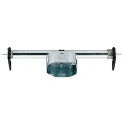
The Saf-T-Brace
®
easily installs through a 4" diameter hole in the ceiling. It is U.L. listed for fan support, and exceeds
the requirements of the National Electric Code for fans weighing up to 70 lbs., for lighting fixtures mounted on 16” cen-
ter joists weighing up to 150 lbs., and lighting fixtures mounted on 24” center joists weighing up to 50 lbs.
Included
non-metallic connector for use with 14-2 and 12-3 AWG sheathed cable.
figure 10figure 9
figure 6
figure 5
figure 1
figure 11
figure 12
figure 2
24” configuration
16” configuration
figure 3
end “A”
figure 4
figure 7
16”
24”
figure 8
16”
24”
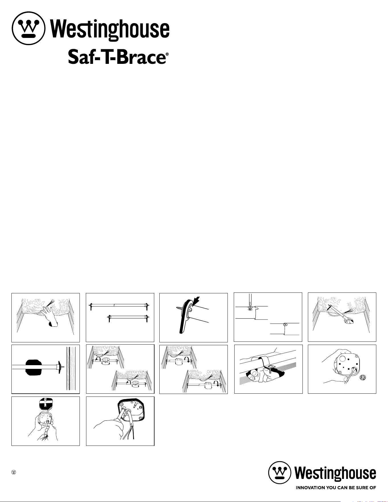
INSTALLATION INSTRUCTIONS
Turn off electrical power at breaker!
1. If there is not a hole where you want to hang the fan, cut a hole in the sheetrock using the electrical box provided as a template. Be cautious of
sharp teeth and screws on each end of the Saf-T-Brace
®
. Clear the installation site of any insulation, wiring and existing lightweight bar hanger
(figure 1). Remove wiring from the sides of the joist.
2. Determine if you have 16” or 24’ ceiling joist centers (figure 2). The Saf-T-Brace
®
is preset at the factory for 16”centers. If you have 24” centers,
you will need to slide the inner tube (end “A”) out about 8” (figure 3) and insert the small sheet metal screw provided in the hole of the inner
tube. After installing this stop screw, slide the notch on the outer tube up to lock it around the screw (figure 4).
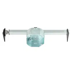
3. Insert Saf-T-Brace
®
through the opening in the ceiling as shown (figure 5). It may be necessary to insert the Saf-T-Brace
®
parallel to the ceiling
joist and then turn it perpendicular to the joist above the sheetrock. Once Saf-T-Brace
®
is in the attic and standing on the sheetrock, the outer
tube must be positioned over the hole. If it is not, turn the brace 180 degrees. Center the brace over the hole in the sheetrock (figure 6).
4. Using one hand, push end “A” toward the ceiling joist and screw into the wood until it is hand tight (figure 7). Do not use pliers or a wrench.
During this process, the outer tube acts as a notched screwdriver.
5. Slide the outer tube (end “B”) toward the opposite joist. Screw end “B” into the joist until it is hand tight (figure 8). Do not use pliers or a
wrench.
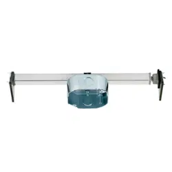
6. Snap the bracket over the outer tube and center it over the hole with the screws facing downward (figure 9).
7. Remove one of the knockouts from the electrical box and install the yellow wire connector (figure 10).
8. Make sure electrical power is off! Pull the wires down through the hole in the sheetrock and push them through the connector from the top of the
electrical box (figure 11).
9. Insert the electrical box into the hole on the ceiling and onto the bolts of the bracket. Secure the electrical box to the bracket with the two nylon
locknuts (figure 12). Be sure to tighten the locknuts securely!
Do not overtighten.
10. When you are ready to hang the fan or fixture, remove Saf-T-Cap
®
. Install fan or fixture screwing the 10-24 x
3
⁄4” bolts into the threaded inserts,
NOT THE ELECTRICAL BOX EARS! Box ears can be used to mount lightweight fixtures or cover plates. Finish installation according to fan or
fixture manufacturer’s instructions.
Westinghouse Lighting, Philadelphia, PA 19154-1029, U.S.A.
www.westinghouselighting.com
and Westinghouse are trademarks of
Westinghouse Electric Corporation.
Used under license by Westinghouse Lighting.
All Rights Reserved.
Made in China

Juego Completo de Instalacion para
el Montaje de Abanicos de Techo y
Accessorios de Iluminación
MODELO 01010
La Saf-T-Brace
®
se instala fácilmente a través de un agujero de 4 pulg. (10,16 cm) de diámetro en el techo. Figura en la lista de UL para soportar
ventiladores y excede los requisitos del Código Eléctrico Nacional (National Electrical Code) para ventiladores que pesan hasta 70 libras (32 kg), para
artefactos de iluminación con un peso de hasta 150 libras (68 kg) montados en vigas que tienen 16 pulg. (40,64 cm) entre centros, y artefactos de
iluminación con un peso de hasta 50 libras (22,7 kg) montados en vigas que tienen 24 pulg. (60,96 cm) entre centros. Incluye abrazadera no metálica
para uso con cableado envainada de tamaño 14-2 o 12-3 AWG.
INSTRUCCIONES PARA INSTALACION
¡Apague la corriente eléctrica en el disyuntor!
1. Si no hay hueco donde usted desea colgar el ventilador, corte un hueco en la plancha de estuco usando la caja de empalme como guia. Cuidado
con los dientes y tornillos afilados en ambos extremos del Saf-T-Brace
®
. Aclare el sitio donde va a instalar de cualquier aislamiento, cableado o
barra colgante de las luces existentes (figura 1). Quite el cableado de los lados de la vigueta.
2. Determine si usted tiene centros de 16” o 24” en las viguetas del techo (figura 2). El Saf-T-Brace
®
esta preprogramado en la factoria para centros
de 16”. Si usted tiene 24” usted necesita deslizar hacia afuera el tubo interior (extremo “A”) como 8” (figura 3) y entrar el tornillo pequeño para
plancha de metal provisto en el hueco del tubo interior. Despues de instalar es tornillo de retencion, deslize la muesca en el tubo exterior hacia
arriba para asegurarlo alrededor del tornillo (figura 4).
3. Entre el Saf-T-Brace
®
atraves del hueco en el techo como se muestra (figura 5). Talvez sea necesario que entre el Saf-T-Brace
®
paralelo a la
vigueta del techo y entonces dar vueltas perpendicular a la vigueta sobre la plancha de estuco. Una vez que Saf-T-Brace
®
esta en el atico y este
parado en la plancha de estuco, el tubo exterior no debe estar posicionado sobre el hueco. Si no esta, gire la abrazadera 180 Grados. Centralize la
abrazadera sobre el hueco en la plancha de estuco (figura 6).
4. Usando una mano, empuje la vigueta del techo en la madera hasta que este apretado bien a mano (figura 7). No use alicate o una llave.
Durante este proceso, el tubo exterior hace el papel de destornillador con muesca.
5. Deslize el tubo exterior (extremo “B”) hacia la vigueta opuesta. Atornille el extremo “B” dentro de la vigueta hasta que este bien apretado bien a
mano (figura 8). No use alicate o llave.
6. Cierre automáticamente la abrazadera sobre el tubo exterior y ponga en el centro sobre el hueco con los tornillos boca abajo (figura 9).
7. Quite uno de los huecos de la caja de empalme e instale el conector de cable amarillo (figura 10).
8. ¡Asegurese que la energía eléctrica este apagada! Hale los cables hacia debajo através del hueco en la plancha de estuco y empuje através del
conector de encima de la caja de empalme (figura 11).
9. Entre la caja de empalme en el hueco en el techo y sobre las pernas de la abrazadera. Sujete la caja de empalme a la abrazadera con las dos
tuercas de nilon (figura 12). ¡Asegurese que apriete bien las tuercas! No sobre apriete.
10. Cuando este listo para colgar el ventilador o adorno, quite la Saf-T-Cap
®
. Instale el Ventilador o Adorno atornillando las tuercas de 10-20 x
3
⁄4” en
los intercalados con roscados, NO LAS OREJAS DE LA CAJA! Las orejas de la caja pueden ser usados para montar los adornos ligeros o chapas
de cubiertas. Termine de instalar de acuerdo a las instrucciones del ventilador o adorno.
figura 10
figura 9
figura 6
figura 5
figura 1
figura 11
figura 12
figura 2
24” configuration
16” configuration
figura 3
end “A”
figura 4
figura 7
16”
24”
figura 8
16”
24”
Westinghouse Lighting, Philadelphia, PA 19154-1029, U.S.A.
www.westinghouselighting.com
and Westinghouse are trademarks of
Westinghouse Electric Corporation.
Used under license by Westinghouse Lighting.
All Rights Reserved.
Made in China