Quick Reference Installation Guide
810006 v1.00 08.24 G5 BC Quick Reference Installation Guide
1
Quick Reference Installation Guide
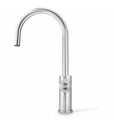
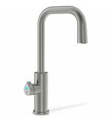
Zip HydroTap G5
Command Centre -
BC HOME, BC H HOME, BC20, BC20 H, BC30, BC30 H,
BC40, BC40 H, BC60, BC60 H, BC100, BC100 H
1
2
Read the safety information
overleaf.
!
!
!
!
UV
!
Contact us if you need support and advice.
Follow these steps for a safe and effective install.
Full installation
instructions
BC Home, BC H Home
BC20, BC20 H
BC30 , BC30 H
Installation
videos
Full installation
instructions
BC40, BC40 H
BC60, BC60 H
BC100, BC100 H
!
!
This QRIG may be sufficient
for installers who have
had previous HydroTap
installation experience.
Inexperienced installers
please scan the QR codes
for detailed installation
instructions.
Zip Water UK
Trafalgar House, Rash’s Green, Dereham,
Norfolk, NR19 1JG
United Kingdom, Tel 0345 6 005 005
Zip Water Australia
67 - 77 Allingham Street, Condell Park NSW 2200
Postal: Locked Bag 80, Bankstown 1885
Australia, Tel (+612) 9796 3100, Free call 1800 947 827 (1800 ZIP TAP)

2
Quick Reference Installation Guide
810006 v1.00 08.24 G5 BC Quick Reference Installation Guide
Safety information
This document is a Quick Start Installation Guide. Download &
read the full Command Centre installation instructions for more
installation information.
!
!
!
!
!
UV
!
Read the
instructions
WARNING
Danger of
electric shock
Highly
flammable
Compressed
Gas WARNING
!
!
HOT
Surface
Explanation of symbols
Lithium
Coin cell
• Compliance : In Australia electrical installation must comply with AS/NZS3000.
• In Australia plumbing installation must comply with AS/NZS3500.
• In Australia For residential chilled models, all refrigeration must comply with AS/NZS
60335.2.24. In the UK the system must be installed in accordance with water supply by-laws,
current IEEE regulations and local authority by-laws.
• This appliance is not intended for use by children under 8 years or persons (including
children under 8 years) with reduced physical, sensory or mental capabilities, or lack
of experience and knowledge, unless they have been given supervision or instruction
concerning the use of the appliance by a person responsible for their safety. Children should
be supervised to ensure that they do not play with the appliance.
• The Zip HydroTap Command Centre range uses HIGHLY FLAMMABLE R290 refrigerant
under pressure.
• Check the rating plate or contact Zip before commencing work.
• To avoid hazards, all installation procedures must be carried out by a suitably qualified
tradesperson. Maintenance of the refrigeration unit specifically must be carried out by an
accredited service provider or qualified refrigeration technician. Faulty operation due to
unqualified persons working on this product may void warranty coverage.
• Warning! Keep ventilation openings in the appliance enclosure or in the built-in structure
clear of obstruction.
• Do not use mechanical devices or other means to accelerate the defrosting process,
other than those recommended by the manufacturer.
• Do not store explosive substances such as aerosol cans with a flammable propellant in
this appliance.
• The HydroTap G5 Home series is intended to be used in household and similar
applications such as:
• Staff kitchen areas in shops, offices and other working environments;
• Farm houses and by clients in hotels, motels and other residential type environments;
• Bed and breakfast type environments;
• Catering and similar non-retail applications.
• For continued safety of this appliance it must be installed, operated and maintained in
accordance with the manufacturer’s instructions.

Quick Reference Installation Guide
810006 v1.00 08.24 G5 BC Quick Reference Installation Guide
3
• This appliance may deliver water at high temperature. Refer to the Plumbing Code of
Australia (PCA), local requirements and installation instructions to determine if additional
delivery temperature control is required.
• The button/coin battery is hazardous and is to be kept away from children. It can cause
severe or fatal injuries in 2 hours or less if it is swallowed or placed inside any part of the
body. Medical attention should be sought immediately if it is suspected the battery has
been swallowed or placed inside any part of the body.
• The Zip HydroTap must be earthed. Earthing is provided via the supplied power cord. The
resistance of the earth connection to each exposed metal part must be less than 1Ω. Use the
power cable supplied. Power point earthing is the responsibility of the installer.
• Do not remove the cover of the appliance under any circumstances without first
isolating the appliance from the power supply.
• Connect only to a potable (wholesome, cat1) mains water supply.
• The new hose sets supplied with the product must be used. Do not re-use old hose sets.
• Never locate the system near, or clean with water jets.
• The integrated vent provides a safe exhaust for the refrigerant gas in the event of a leak.
• The power cord and general power outlet must be in a safe and accessible position after
installation. When positioning the appliance, ensure the power supply cord is not trapped or
damaged. If the power supply cord is damaged it must be replaced by a Zip service provider or a
qualified electrician.
• Do not locate multiple portable socket-outlets or portable power supplies at the rear of
the appliance.
Safety information
4
Quick Reference Installation Guide
810006 v1.00 08.24 G5 BC Quick Reference Installation Guide
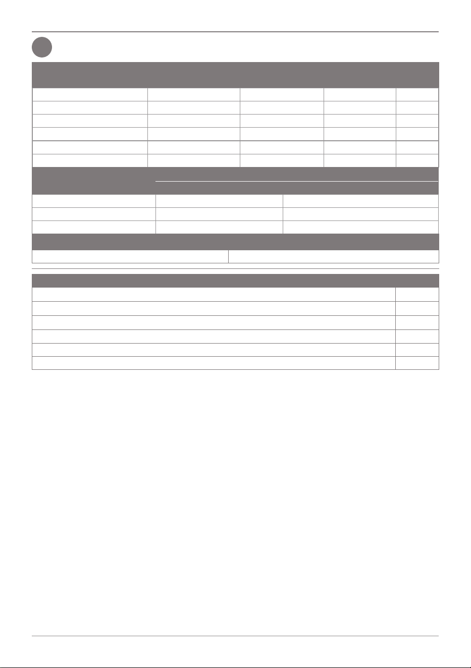
Installation -Technical data, part supplied
Review the technical data & parts supplied in the kit.
Model
Power rating, kW
220-240V, 50Hz
Dimensions
W x D x H (mm)
Water supply
Connection
Weight
(kg)
BC100,BC100 H 2.1 + Booster 395 x 487 x 333 G 1/2 30
BC60,BC60 H 2.1 395 x 487 x 333 G 1/2 30
BC40,BC40 H 1.97 395 x 487 x 333 G 1/2 30
BC30,BC30 H 1.9 + Booster 280 x 478 x 333 G 1/2 23
BC20,BC20 H 1.9 280 x 478 x 333 G 1/2 23
BC Home,BC H Home 1.44 280 x 478 x 333 G 1/2 23
Component
Min - Max pressure, kPA (bar)
Australia UK
HydroTap 170 (1.7 ) - 700 (7.0) 170 (1.7) - 500 (5.0)
Vented Mixer Tap 300 (3.0) - 700 (7.0) 200 (2.0) - 500 (5.0)
Booster & Limescale filter 200 (2.0) - 700 (7.0) 200 (2.0) - 500 (5.0)
Booster electrical rating
230V 50/60Hz - 2.20kW 240V 50/60Hz - 2.40kW
Parts supplied with the Command Centre
Command Centre, instructions, power cable, supply hose, door buffers.
Vent kit inc. 2 Exhaust vent mounting plates,(use either, depending on cupboard overhang)
Water supply inlet adaptor and strainer.
Install rail kit (inc isolation valve), & instructions. (UK only)
Booster & hoses. Optional
Limescale filter kit. Optional
3
Quick Reference Installation Guide
810006 v1.00 08.24 G5 BC Quick Reference Installation Guide
5
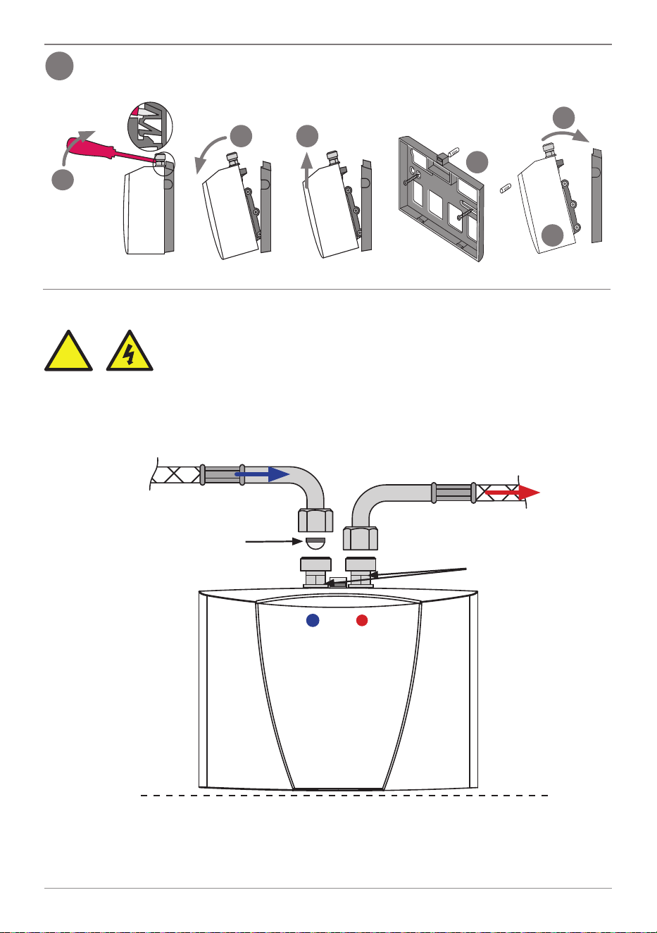
Ventilation installation instructions
4
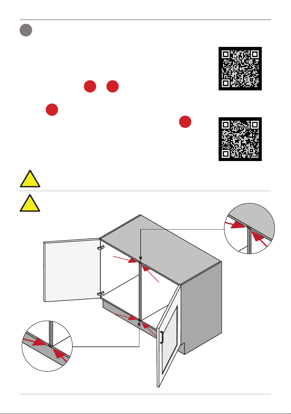
Make sure there’s enough ventilation in the cupboard, air needs to circulate as follows:
Cold air is drawn in through the gaps provided by the door buffers
(supplied), they must be fitted. Command Centre clearances
must be observed.
Warm air is expelled through the integrated vent in the base of the
Command Centre, via the vent cut-out in the cupboard floor.
If installing in a warm space, use optional extra, inlet vent .
The inlet vent cut-out may be positioned in the cupboard side, door
or floor (depending on cupboard size and overhang).
Observe 100mm inlet / outlet vent separation.
To install the mounting plate & optional extra inlet vent grilles,
scan the QR Codes , follow the instructions:
A vent mounting plate or (supplied) covers the cut out.
c
b
a
If installing in a cupboard with less than 40mm overhang,
use vent
too.
d
Ventilation
Installation
Video
!
The door buffers (supplied) must be fitted to the cupboard, for each
door, in all installations, to maintain effective airflow. See below:
Bottom door
buffers
Top door
buffers
Ventilation
Installation
Instructions
Incorrect ventilation installation may void warranty
coverage.
!
6
Quick Reference Installation Guide
810006 v1.00 08.24 G5 BC Quick Reference Installation Guide
Ventilation installation instructions
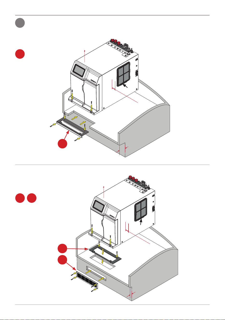
Option 1: Ventilation arrangement using small cupboard with min. 40mm overhang
Directing warm air straight into
the room.
40mm min. overhang
50mm min
Clearance
beside inlet
200mm
Clearance
a
Inlet
Must be
installed
a
Must be installed
BC Home, BC H Home, BC20, BC20 H, BC30, BC30 H ventilation options
Option 2: Ventilation arrangement using small cupboard with less than 40mm, or no
overhang. Directing warm air into
the kick space & out through a
vent grille.
Less than 40mm or no
overhang
50mm min
Clearance
beside inlet
200mm
Clearance
b
d
Must be
installed
b
d
Both
must be
installed
Inlet
5
Quick Reference Installation Guide
810006 v1.00 08.24 G5 BC Quick Reference Installation Guide
7
6
Ventilation installation instructions
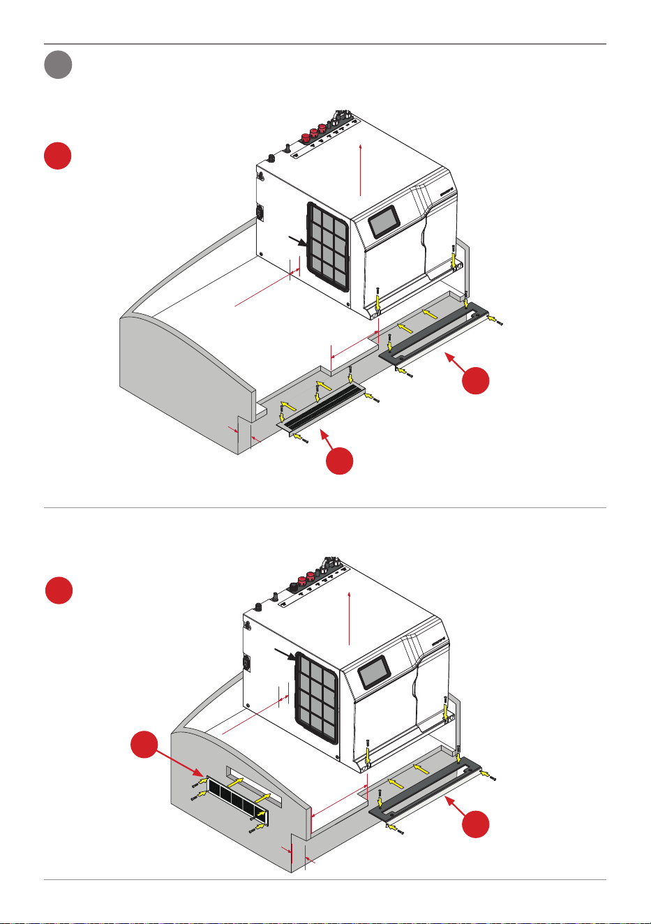
Option 3: Ventilation arrangement using large cupboard with min. 40mm overhang
Directing warm air straight into
the room.
40mm min overhang
100mm
min
50mm min.
clearance
beside inlet
200mm
Clearance
a
Inlet
c
Extra Inlet
vent option
Must be
installed
a
Must be installed
BC40, BC40 H, BC60, BC60 H, BC100, BC100 H ventilation options
Option 4: Ventilation arrangement using small cupboard with min. 40mm overhang
Directing warm air straight into
the room.
a
Must be installed
100mm
min
40mm min overhang
200mm
Clearance
50mm min.
clearance
beside
inlet
a
Must be
installed
c
Extra Inlet
vent option
Inlet
8
Quick Reference Installation Guide
810006 v1.00 08.24 G5 BC Quick Reference Installation Guide
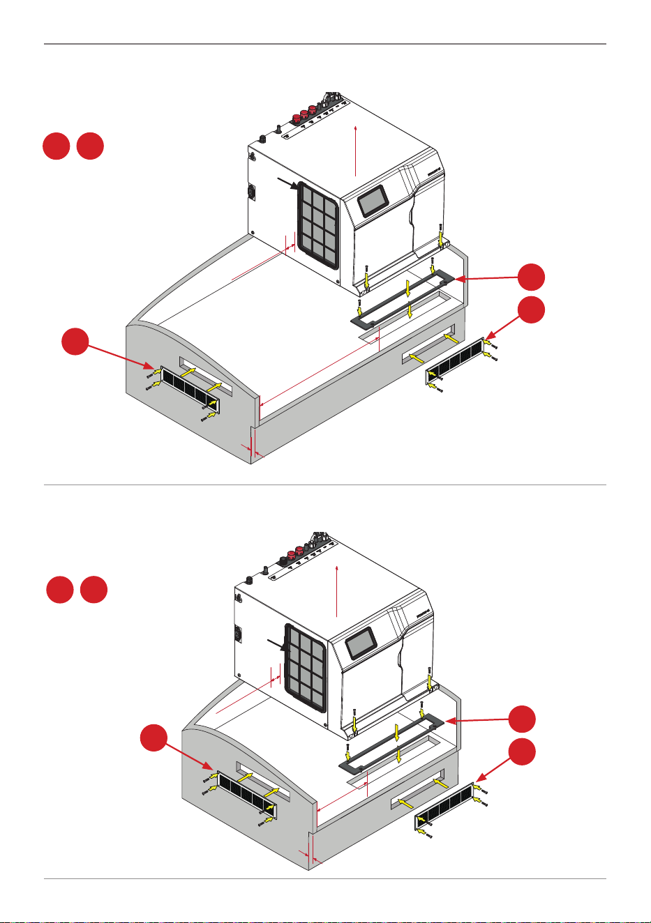
100mm min
Less than 40mm
or no overhang
50mm min.
clearance
beside inlet
200mm
Clearance
b
c
d
Both
must be
installed
Option 5: Ventilation arrangement if using a large cupboard with less than 40mm, or no
overhang. Directing warm air into
the kick space & out through a
vent grille.
Extra Inlet
vent option
Inlet
b
d
Must be
installed
Ventilation installation instructions
Option 6: Ventilation arrangement if using small cupboard with less than 40mm, or no
overhang. Directing warm air into
the kick space & out through a
vent grille.
100mm
min
Less than 40mm
or no overhang
50mm min.
clearance
beside
inlet
200mm
Clearance
c
b
d
Both
must be
installed
Inlet
b
d
Must be
installed
Extra Inlet
vent option
Quick Reference Installation Guide
810006 v1.00 08.24 G5 BC Quick Reference Installation Guide
9
7
If supplied as part of the kit mount the Booster as follows:
a
b
10⁰
c
d
e
f
15⁰
Installation - Ancillary components, Booster
Booster
Hold connections
with spanner
while tightening hoses
Strainer
Cold water into Booster,
connect to Command Centre
BYPASS OUT
Hot water out of Booster,
connect to Command Centre
BYPASS IN
Mount
horizontally
Connect the braided hoses to the Booster:
Do not over tighten hose connections. Braided hoses supplied cannot
be lengthened.
!
!
!
Mount
horizontally
10
Quick Reference Installation Guide
810006 v1.00 08.24 G5 BC Quick Reference Installation Guide
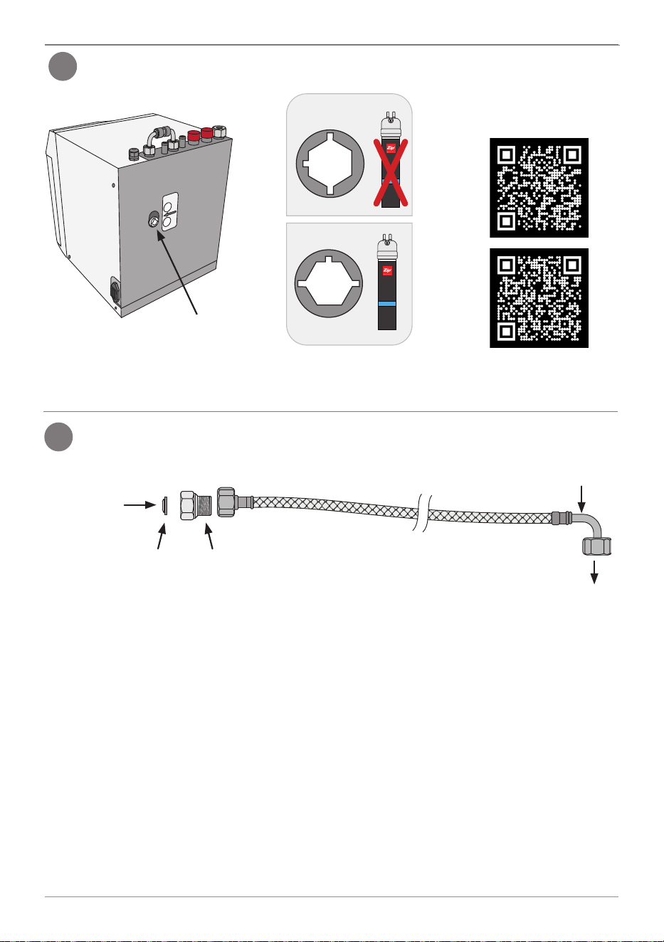
Bypass valve
UK only If installing a limescale filter, set the bypass valve (Rear of the Command Centre).
9560395601, 95602
Scan the QR Codes &
read the filter instructions
8
Installation - Ancillary components, Limescale filter
Make sure the braided hose and adaptor arrangement for the mains water
supply are installed as follows:
Mains cold
water supply
Inline filter
adaptor
Inline
filter
90º bend
Command
Centre
9
General installation arrangement instructions
Quick Reference Installation Guide
810006 v1.00 08.24 G5 BC Quick Reference Installation Guide
11
Command
Centre
BC Home, BC H Home, BC20, BC20 H, BC30, BC30 H Installation
!
Install Rail
UK only
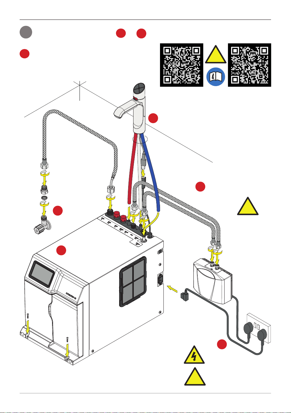
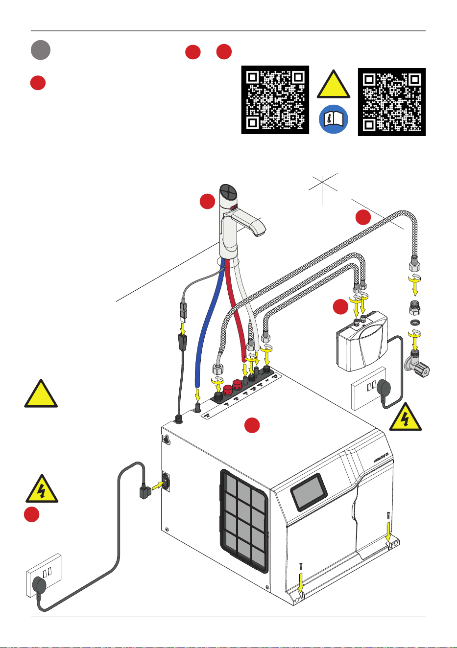
10
Install the HydroTap in order to .
a
f
Establish the water
supply (install inlet
adaptor & hose).
Fit the Booster & hoses
(if supplied in the kit).
c
d
DO NOT
SWITCH ON
Booster until
Commissioning.
e
f
Connect to
the power supply
DO NOT SWITCH ON
Command Centre until
Commissioning.
!
For UK, fit the install
rail (scan the QR Code
for instructions).
!
!
!
Fit the tap connections:
RED silicone - Boiling Out
Clear silicone - Vent
Blue silicone -Chilled Out
USB
b
Note For mixer tap
configuration, see full
instruction manual .
a
Install the vent mounting plate
on the cupboard floor, scan the QR Code
& read the instructions.
Install the
Command Centre
Scan the QR Code & read
the instructions
Ventilation Installation
Instructions
12
Quick Reference Installation Guide
810006 v1.00 08.24 G5 BC Quick Reference Installation Guide
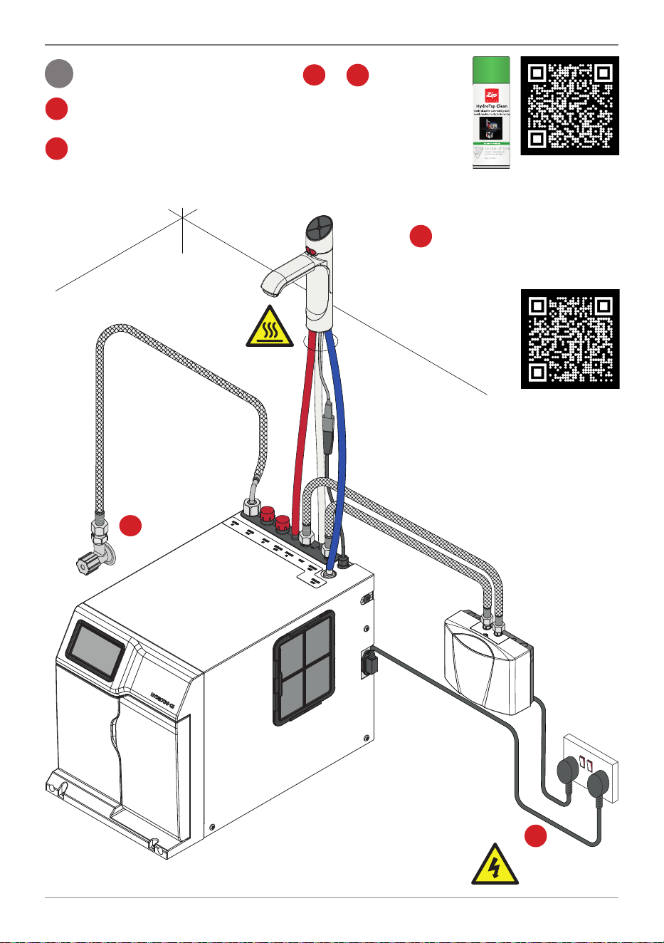
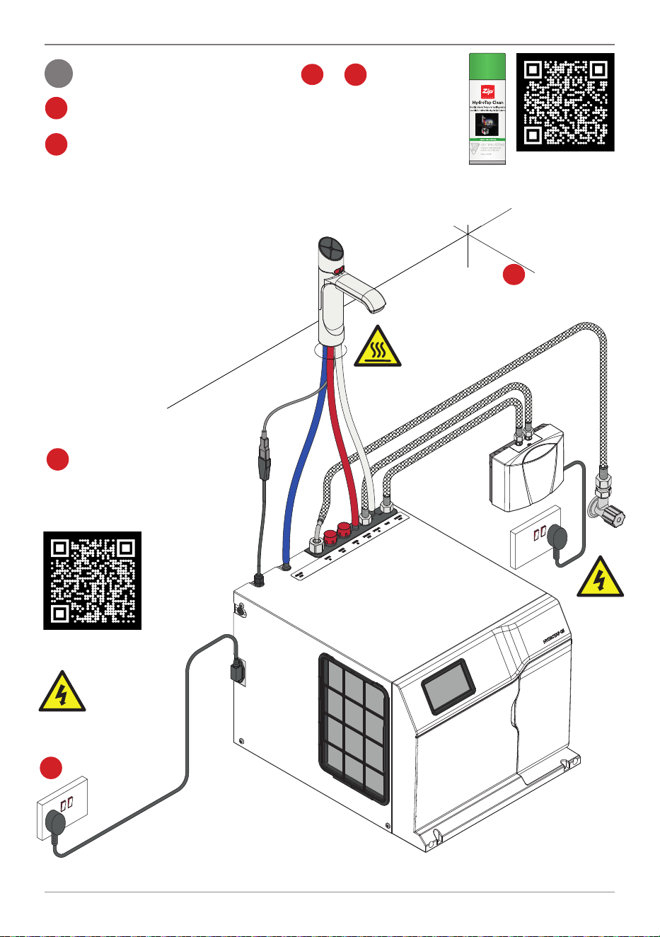
BC Home, BC H Home, BC20, BC20 H, BC30, BC30 H Commissioning
Commission the HydroTap in order to .
HydroTap Clean
If cupboard temperatures exceed 35
O
C additional ventilation
will be required.
Commissioning process, follow screen prompts, scan HydroTap
Clean QR for more information.
Turn on the
power supply.
g
Turn on water
supply & check
for leaks.
h
g
j
k
To use the HydroTap, scan the
User Guide QR Code & read the
instructions.
User Guide
!
!
!
!
k
i
11
Quick Reference Installation Guide
810006 v1.00 08.24 G5 BC Quick Reference Installation Guide
13
BC Home, BC H Home, BC20, BC20 H, BC30, BC30 H Commissioning
Turn on the
power supply.
BC40, BC40 H, BC60, BC60 H, BC100, BC100 H Installation
12
Install the HydroTap in order to .
a
For UK, fit the install
rail (scan the QR Code
for instructions).
Fit the Booster
& hoses
(if supplied
in the kit).
c
!
DO NOT
SWITCH ON
Booster or Command
Centre until
Commissioning.
d
e
Connect to the
power supply.
Scan the QR Code & read
the instructions
Install Rail
(UK only)
!
!
!
!
!
Fit the tap connections:
RED silicone - Boiling Out
Clear silicone - Vent
Blue silicone - Chilled Out
USB
f
Note For mixer tap
configuration, see full instruction manual.
a
b
Install the
Command Centre
f
Establish the water
supply (install inlet
adaptor & hose).
Install the vent mounting plate
on the cupboard floor, scan the QR Code
& read the instructions.
Ventilation Installation
Instructions
14
Quick Reference Installation Guide
810006 v1.00 08.24 G5 BC Quick Reference Installation Guide
Commission the HydroTap in order to .
Commissioning process, follow screen prompts, scan HydroTap
Clean QR for more information.
To use the HydroTap, scan
the User Guide QR Code & read
the instructions.
User Guide
BC40, BC40 H, BC60, BC60 H, BC100, BC100 H Commissioning
Turn on water
supply &
check for leaks.
Turn on the
power supply.
HydroTap Clean
If cupboard
temperatures exceed
35
O
C additional
ventilation will be
required.
!
!
!
!
!
!
13
g
k
h
i
j
g
k

Quick Reference Installation Guide
810006 v1.00 08.24 G5 BC Quick Reference Installation Guide
15
Notes

16
Quick Reference Installation Guide
810006 v1.00 08.24 G5 BC Quick Reference Installation Guide
Refer to User Guide for operation and maintenance.
As Zip policy is one of continuous product improvement, changes to specifications may be made without
prior notice. Images in this booklet have been modified and may not be true representations of the
finished goods.
The terms “Zip” and “HydroTap” are registered trade marks of Zip Heaters (Aust) Pty Ltd.