EN
Original Instructions
Version 1
08 557
500kg
TRANSMISSION
JACK
1.1 Product Reference
User Manual for: Draper Expert Evolution Transmission
Jack, 500kg
Stock No: 08557
Part No: TJ500EVO
1.2 Revisions
Version 1: March 2023
First release
As our manuals are continually updated, always ensure
that the latest version is used.
Please visit drapertools.com/manuals for the latest
version of this manual and the associated parts list, if
applicable.
1.3 Understanding the Safety Content of
This Manual
WARNING!
– Situations or actions that may result
in personal injury or death.
CAUTION! – Situations or actions that may result
in damage to the product or surroundings.
Important: – Information or instructions of particular
importance.
1.4 Copyright © Notice
Copyright © Draper Tools Limited.
Permission is granted to reproduce this manual for
personal and educational use ONLY. Commercial
copying, redistribution, hiring or lending is strictly
prohibited.
No part of this manual may be stored in a retrieval system
or transmitted in any other form or means without written
permission from Draper Tools Limited.
In all cases, this copyright notice must remain intact.
1. Preface
– 2 –
These are the original product instructions. This
document is part of the product; retain it for the life
of the product, passing it on to subsequent holders.
Read this manual in full before attempting to
assemble, operate or maintain this product.
This Draper Tools manual describes the purpose
of the product and contains all the necessary
information to ensure its correct and safe use.
Following all the instructions and guidance in
this manual will ensure the safety of both the
product and the operator and increase the
lifespan of the product.
All photographs and drawings within this manual are
supplied by Draper Tools to help illustrate correct
operation of the product.
Every eort has been made to ensure the
information contained in this manual is accurate.
However, Draper Tools reserves the right to amend
this document without prior warning. Always use the
latest version of the product manual.
EN

2. Contents
– 3 –
EN
1. Preface 2
1.1 Product Reference 2
1.2 Revisions 2
1.3 Understanding the Safety Content of This
Manual 2
1.4 Copyright © Notice 2
2. Contents 3
3. Product Introduction 4
3.1 Intended Use 4
3.2 Specication 4
4. Health and Safety Information 5
4.1 General Health and Safety Instructions for this
Product 5
4.2 Correct Use of the Transmission Jack 5
4.3 Residual Risk 6
5. Identication and Unpacking 7
5.1 Product Overview 7
5.2 What’s in the Box? 8
5.3 Packaging 8
6. Assembly Instructions 9
7. Operating Instructions 10
7.1 Preparing the Jack for Use 10
7.2 Operating the Jack 11
8. Maintenance 12
8.1 General Maintenance 12
8.2 Checking and Replacing the Oil 12
8.3 Storing the Jack 12
8.4 Troubleshooting 13
9. Spares, Returns and Disposal 14
10. Warranty 15
11. Explanation of Symbols 16

3. Product Introduction
Stock No. 08557
Part No. TJ500EVO
Rated capacity: 500kg
Working heights:
Minimum height: 90cm
Max. primary ram height: 139cm
Max. secondary ram height: 189cm
Saddle type: Adjustable
Saddle tilt:
Forward: 37°
Backwards: 2°
Sideways: 12°
Saddle size:
Max.: 52.5 x 52.5cm
Min.: 20.5 x 20.5cm
Base dimensions: 77 x 77cm
Net weight: 66kg
– 4 –
EN
3.2 Specication
3.1 Intended Use
This jack is designed for supporting transmission systems
and dierentials within the rated capacities during
installation and removal. Any other application beyond
the conditions established for use will be considered
misuse. Draper Tools accepts no responsibility for
improper use of this product.
Important: This product is NOT suitable for elevating or
supporting vehicles.
Part of our core range, this product is suitable for regular
use by enthusiasts and tradespersons alike.
WARNING! This product is not a toy and must be
respected.
Read this manual in full before attempting to assemble,
operate or maintain the product, and retain it for later use.
4. Health and Safety Information
Important: Read all Health and Safety instructions
before attempting to operate, maintain or repair this
product. Non-compliance with these instructions may
result in injury or damage to the user or the product.
4.1 General Health and Safety
Instructions for this Product
• Only personnel who have read and understood this
manual and are trained in the use of this product and
the relevant forces are authorised to operate this
device.
• Observe all standard safety precautions and good
practices when working in a workshop environment.
• Keep your work environment clear and well-lit, with
bystanders at a safe distance.
• Before every use, inspect the jack for broken, cracked,
loose or corroded parts.
Important: DO NOT use this product if it is damaged
in any way. Contact Draper Tools to discuss repair and
replacement options.
• DO NOT use this product if you suspect that it has
been subjected to abnormal loads or shock and have
it inspected by a qualied technician.
• Ensure that the warning labels and safety instructions
on the product are visible and legible.
• Use the product only in the manner instructed in this
manual and DO NOT modify it in any way.
• ONLY use spare parts supplied by Draper Tools
• DO NOT use this product if you are tired or under the
inuence of alcohol, drugs or other medication.
• ALWAYS wear eye protection and protective gloves
and footwear when assembling or operating the jack.
• Keep loose-tting clothes, jewellery and long hair tied
back to prevent it from snagging during operation.
• The wheels of this product DO NOT lock.
− Ensure that the jack will not roll once positioned
for use.
• ALWAYS ensure that the load is stable and secure in
the saddle and that the saddle parts are rmly
secured before raising, lowering or transporting the
load.
• Before moving the jack, ALWAYS inspect the intended
route and ensure that it is clear of obstructions.
• Take care when moving the jack.
− ALWAYS ensure that the load is fully secure
before moving the jack.
− DO NOT use the jack on uneven surfaces that may
cause it to tip over.
− ALWAYS bring the load to its lowest possible
position before transportation.
• NEVER leave the jack unattended when it is in use or
under load.
• When not in use, ensure that the ram is in its lowest
position and the release valve is fully closed.
• This jack does not emit noise that exceeds a level of
70 dB(A) during operation.
WARNING!
If the jack tips or leans while under
load, move immediately to a safe distance. DO
NOT attempt to steady or hold the jack.
4.2 Correct Use of the Transmission Jack
CAUTION! This product is designed to support
loads for short periods ONLY. DO NOT use this
product to support a load for longer than
30 minutes at a time.
• ALWAYS bleed the jack before use.
• ONLY operate the jack on solid, level and horizontal
surfaces.
− A concrete surface is recommended, where
possible.
W
ARNING! NEVER use the jack on any
surface that is slippery or may sink or rock.
• NEVER attempt to lift or support any load that
exceeds the rated capacity of the jack.
• NEVER attempt to lift any load higher than the
maximum safe height of the jack.
• DO NOT use excessive force when opening and
closing the release valve as this may damage the
piston.
• NEVER use a power tool to adjust the tilt screws.
• When attaching a load to the jack, ALWAYS use the
manufacturer’s recommended contact points.
• Ensure that the contact points are not dirty, greasy or
corroded.
• Ensure that the harnessing strap is as tight as possible
and eectively hold the load in position.
• ALWAYS ensure that the load is fully detached from
its surroundings before moving it.
– 5 –
EN

4. Health and Safety Information
• NEVER allow anyone to position themselves or other
obstructions beneath the load during raising and
lowering or below any load supported only by the
jack.
• DO NOT stand or climb on the jack.
• To prevent overloading, the jack is tted with an
overload valve set at the factory.
Important: The overload valve MUST NOT be
adjusted under any circumstances. If the safe
capacity of the jack is exceeded, the valve will prevent
the lifting operation.
• Take all precautions to prevent movement of the load
during raising and lowering.
− Be aware that external forces may cause the load
to rock.
• Stay alert to external interference that may cause the
raised load to rock during preparation and operation.
− Should any dangerous conditions occur, cease all
operation until these conditions have been
rectied.
• Stay alert to the possibility of the load slipping from
the saddle and remain observant at all times.
• ALWAYS ensure that the vehicle is raised to the
correct height before attempting to move the jack
underneath it.
• ALWAYS ensure that the vehicle is level and
adequately supported before removing the
transmission or dierentials.
• Take any necessary precautions to prevent the vehicle
from sliding, including chocking the wheels (Rubber
Wheel Chocks, Stock No. 54500, for example).
• DO NOT move the jack further than is absolutely
necessary while under load.
− ALWAYS ensure that the route from the location
of engine to its destination is clear of obstructions
and is as short as possible.
• If the jack vibrates excessively during use, have the
product serviced by a qualied and authorised
technician.
W
ARNING! NEVER work under an unsupported
vehicle.
4.3 Residual Risk
The safety instructions in this manual cannot account for
all possible conditions and situations that may occur.
Exercise common sense and caution when using this
product and protect against any additional conceivable
risks.
– 6 –
EN
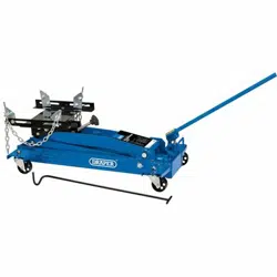
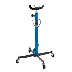
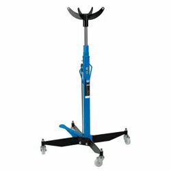
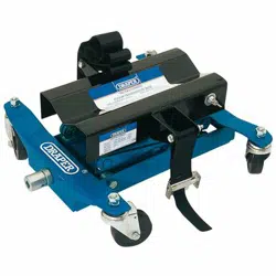
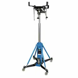
5. Identication and Unpacking
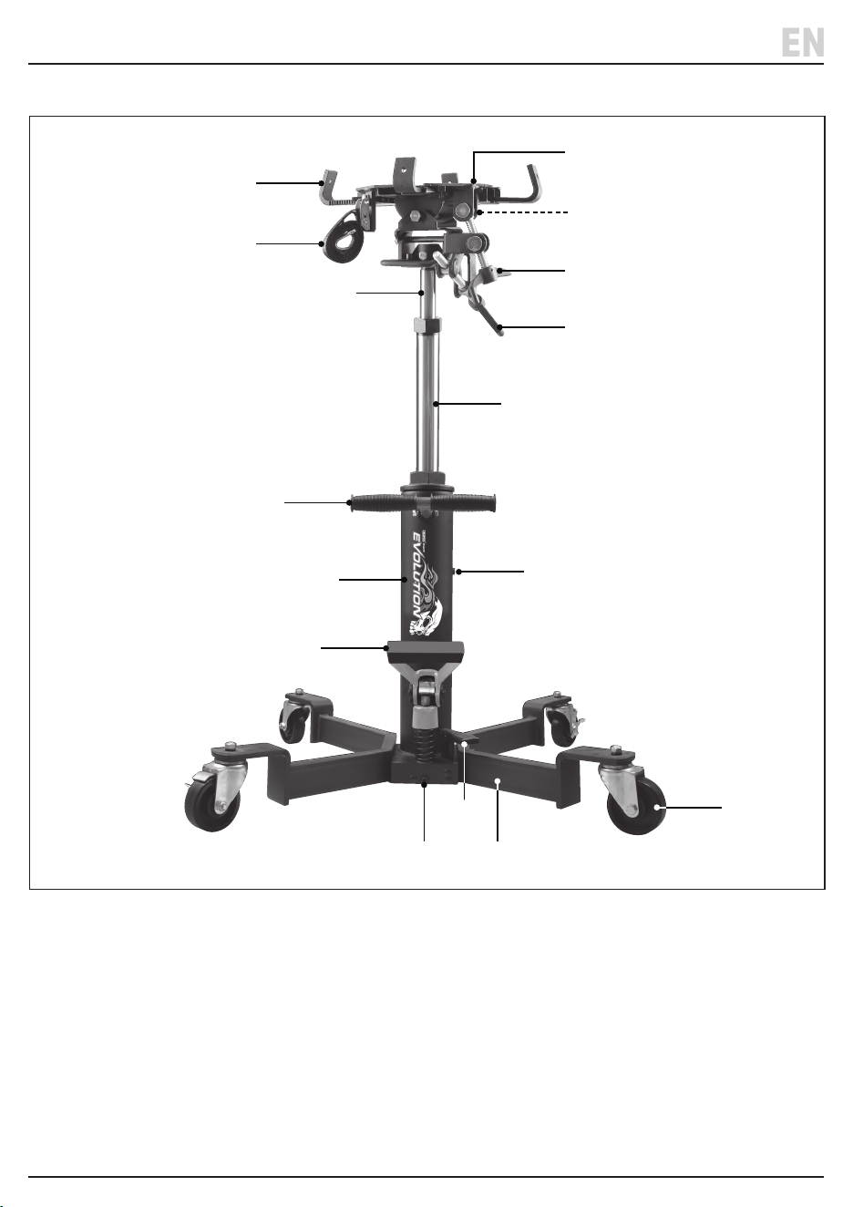
5.1 Product Overview
(1) Base frame
(2) Castors
(3) Forward/backward tilt handle
(4) Hydraulic unit
(5) Left/right tilt handle
(6) Oil ller cap
(7) Overload valve
(8) Primary ram
(9) Pump pedal
(10) Release valve pedal
(11) Saddle
(12) Saddle rachet arms
(13) Strap
(14) Strap attachment loop
(15) Secondary ram
(16) Transport handle
– 7 –
EN
(1)
(12)
(13)
(11)
(14)
(16)
(4)
(2)
(8)
(5)
(3)
(6)
(7)
(15)
(9)
(10)
5. Identication and Unpacking
5.3 Packaging
Keep the product packaging for the duration of the
warranty period for reference should the product need to
be returned for repair.
WARNING! Keep packaging materials out of
reach of children. Dispose of packaging
correctly and responsibly and in accordance
with local regulations.
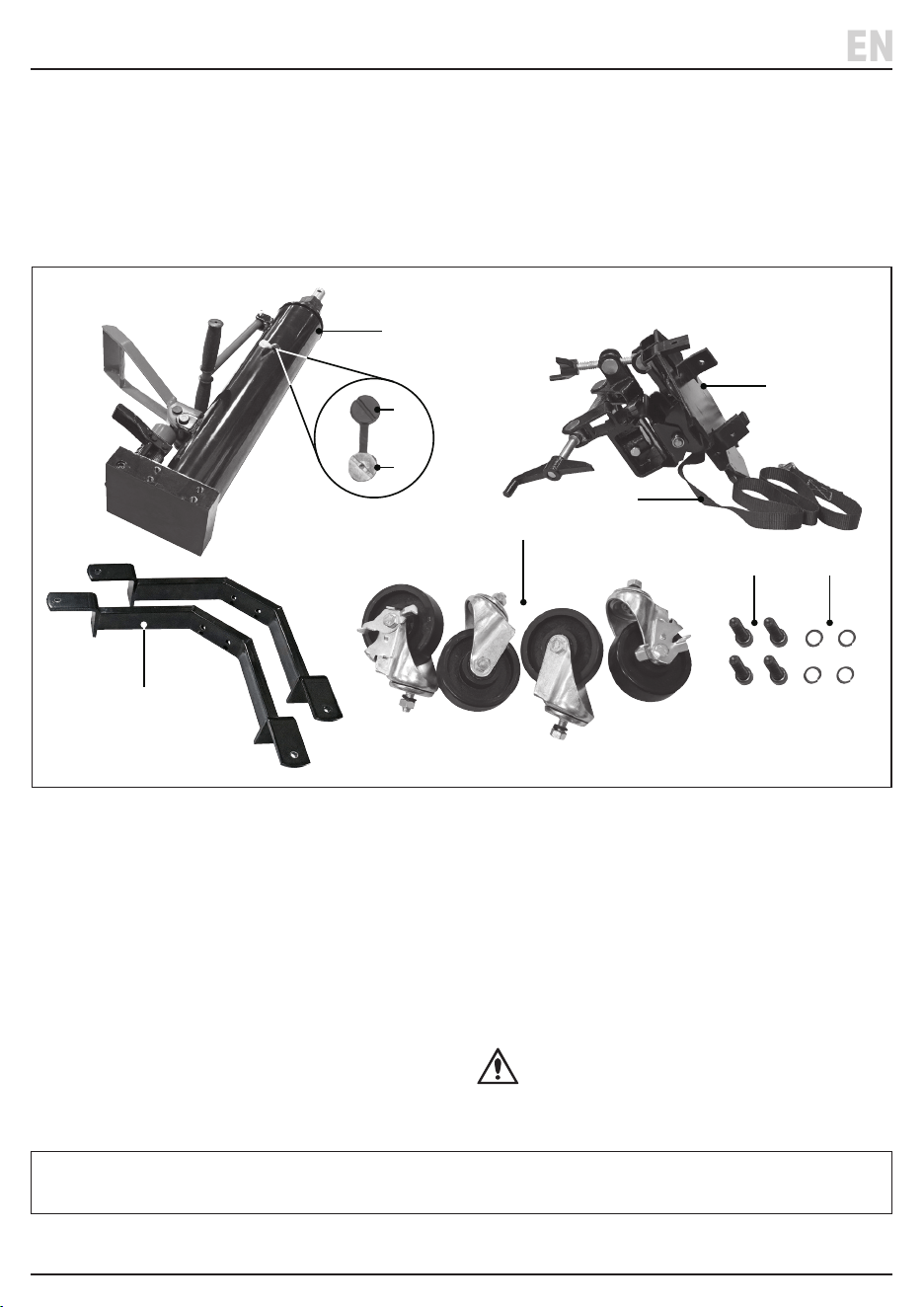
(A) 1 x Hydraulic unit
(B) 2 x Base frame brackets
(C) 1 x Saddle assembly
(D) 2 x Castor assemblies with brakes
(E) 2 x Castor assemblies without brakes
(F) 1 x Strap
(G) 4 x M12 x 45mm socket bolts
(H) 4 x M12 spring washers
(I) 1 x Permanent oil ller screw
(attached to hydraulic unit prior to shipment)
(J) 1 x Temporary oil ller screw
(installed prior to shipment)
Please visit drapertools.com for our full range of accessories and consumables.
– 8 –
EN
5.2 What’s in the Box?
Carefully remove the product from the packaging and
examine it for any signs of damage that may have
occurred during shipment.
Before assembling the product, lay the contents out and
check them against the parts shown below. If any part is
damaged or missing, do not attempt to use the product.
Please contact the Draper Helpline; contact details can
be found at the back of this manual.
(A)
(B)
(F)
(F, E)
(G) (H)
(C)
(J)
(I)

6. Assembly Instructions
Important: Read and understand all the safety
instructions listed in this manual before attempting to
assemble this product. Some parts may be assembled
before shipment.
Important: Hand-tighten all bolts xings during
assembly then tighten them securely once assembly is
complete.
1. Use two M12 x 45mm hex bolts (G) and M12 spring
washers (H) to secure each base frame bracket (B) to
the base of the hydraulic unit (A).
2. Remove the nut and washer from each castor
assembly (D) (E), then pass them up through each
base frame bracket socket and use the washers and
nuts to secure them in place.
Important: Install one castor assembly with brakes
(D) and one without brakes (E) onto each base frame
bracket. The brakes should be located on the castors
on the opposite side to the pedals.
3. Remove the bolt from the saddle assembly (C) socket
and place the saddle assembly over the secondary
ram (15) head.
4. Rotate the saddle assembly to align the socket and
ram head holes and insert the bolt to secure it in
place.
5. Remove the temporary oil ller screw (J) from the
hydraulic unit and replace it with the permanent oil
ller screw (I).
– 9 –
EN
7. Operating Instructions
Important: Before lifting any load, read and understand
all the safety instructions listed in this manual. ALWAYS
test the jack thoroughly, bleed the piston and ensure that
all bolts and attachments are securely fastened before
use.
CAUTION! This product is for lifting
transmission systems and dierentials ONLY.
DO NOT use this product to suspend equipment
for prolonged periods.
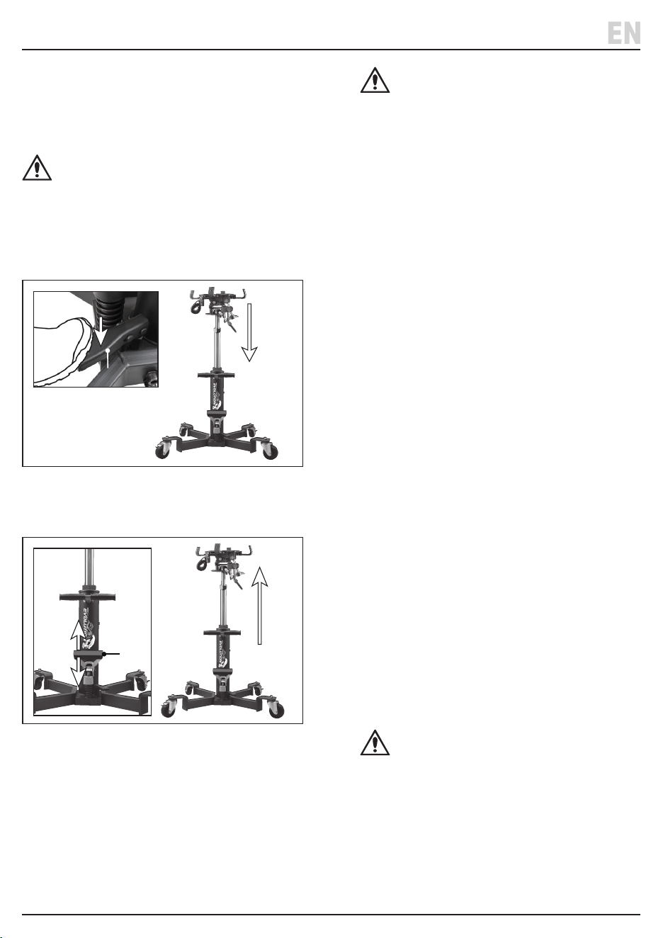
Depressing and holding the release valve pedal opens
the release valve. Releasing the release valve pedal
closes the release valve.
1 Fig.
(10)
Operating the pump pedal (9) raises the ram if the release
valve is closed.
2 Fig.
(9)
7.1 Preparing the Jack for Use
Prepare the jack correctly before EVERY use. For your
safety and comfort, Draper Tools recommends that this
process is carried out by two people working together.
Check the jack for bent, broken, cracked or loose parts,
and oil leaks and ensure that the castors (2) rotate freely.
WARNING! DO NOT use the product if
defects are present. If it is suspected that the
jack has been subjected to abnormal loads or
has suered any knocks, withdraw it from
service until the product has been repaired.
1. Check the piston oil level; see 8.2 Checking and
Replacing the Oil.
2. Bleed the pump:
a. Depress the release valve pedal (10) and allow both
the primary (8) and secondary (15) rams to drop
slowly to their lowest positions.
b. With the release valve pedal still depressed, rapidly
operate the pump pedal (9) at least fteen times
using the full stroke range to lubricate the rams
and expel any accumulated air.
c. Loosen the oil ller cap (6) and allow any additional
air to escape.
d. Release the release valve pedal (10) to close the
valve.
3. Bleed the ram:
a. Use a plain slot screwdriver to slightly loosen the
oil ller cap (6).
b. Lightly depress the pump pedal (9).
c. Tighten the oil ller cap and retest the jack.
4. Test the jack:
a. With the release valve closed, operate the pump
pedal to raise the rams to their highest position.
b. Observe the rams to check that they do not drop.
5. If the primary ram begins to drop without
intervention:
a. Depress the release valve pedal and allow the ram
to drop to its lowest position.
b. Operate the pump pedal another ten times.
c. Manually raise the ram and force it downwards as
quickly as possible several times.
WARNING! When manually lifting the ram,
keep in mind that it will not be held in place
by the piston when raised. Ensure that the
jack does not roll on its castors when the ram
is manually lowered.
d. Release the release valve pedal.
– 10 –
EN

7. Operating Instructions
6. Test the jack again by raising the ram and ensuring
that it extends fully and does not drop without
intervention.
7. Repeat this process several times. If the issue is not
resolved after several attempts, contact Draper Tools
for assistance.
7.2 Operating the Jack
1. Correctly prepare the jack for use; see 7.1 Preparing
the Jack for Use.
2. Raise the vehicle to an appropriate height and secure
it on suitable supports (not supplied).
3. Using the transport handle (16), move the jack into
position beneath the vehicle.
4. Ensure that the release valve is closed (Fig. 1) and
operate the pump pedal (9) to extend the rams until
the saddle (11) contacts the transmission system.
5. Adjust the position of the saddle rachet arms (12) to
properly grip the load by squeezing the locking tabs
either side of each arm and moving the arms as
appropriate.
6. Use the forward/backward (3) and left/right (5) tilt
handles to adjust the angle of the saddle as
appropriate.
7. Ensure that the load is positioned centrally in the
arms of the saddle, then carefully pump up the ram a
little further to transfer the weight of the load from
the vehicle to the jack.
Important: Grip the transport handle during lifting
and lowering to keep the jack steady.
8. Detach the transmission system from the vehicle,
ensuring that movement of the load is not obstructed
in any way.
9. Check that the saddle is securely and comfortably
holding the load and does not show signs of stress.
10. Secure the load tightly to the saddle using the
strap (13).
Important: Attach the strap hook to the strap
attachment loop (14) and use the strap ratchets to
tighten it around the load.
11. Ensure that no one is present beneath the load and
that the load can be lowered without obstruction,
then slowly depress release valve pedal just enough
to allow the ram to drop to its lowest position.
Important: The rate at which the load will drop is
dependent on its weight.
12. Check the saddle again for signs of stress or poor
seating of the load.
13. With the ram in its lowest position, manoeuvre the
jack to a suitable workspace to operate on the load.
14. When work is complete, perform this procedure in
reverse to install the transmission system back into
the vehicle.
– 11 –
EN

8. Maintenance
Important: Maintenance and repair of the jack must only
be performed by qualied personnel with sucient
knowledge of the hydraulics systems used in these
devices. All maintenance should be performed in
accordance with these instructions.
Important: ALWAYS drain the jack of oil before returning
it to Draper Tools for repair.
WARNING! DO NOT attempt to perform any
maintenance on the jack while it is under load.
Safely lower and remove any load from the jack
and drop the ram to its lowest position before
proceeding.
8.1 General Maintenance
• Keep the jack clean and regularly lubricate all moving
parts.
− Dust and debris may cause components to
become clogged or jammed, and the product may
not perform at its best.
• Protect the jack and its components from adverse
environmental and weather conditions, both during
use and when stored.
− The components may rust if exposed to water or
damp air for prolonged periods.
• Before each use, check the jack for signs of damage or
disrepair.
CAUTION! NEVER attempt to open the hydraulic
unit as this may irrevocably damage the
product.
8.2 Checking and Replacing the Oil
To extend the working life of the product, keep the oil at
an appropriate level and replace it after periods of
prolonged intensive use or at least once every year.
CAUTION! Use AW 22 hydraulic oil. Never use
brake or engine oil. DO NOT pump the piston
while topping up the oil.
WARNING! Oil spillage may cause the operating
surface to become slippery. Do not operate the
jack on oily surfaces.
1. Place the jack on a level, horizontal surface.
2. Open the release valve using the pedal (9) and fully
lower the rams.
3. Carefully unscrew and remove the oil ller cap (6).
4. If the oil must be drained, with assistance, tip the jack
and allow the oil to completely drain from the piston
into a suitable container.
5. Tip the jack upright and carefully pour oil into the
opening until it is completely full.
6. Replace the oil ller cap and wipe up any spillages.
7. Ensure that all xings are tight, then bleed and test
the jack; see 7.1 Preparing the Jack for Use.
Important: Dispose of oil according to local regulations.
8.3 Storing the Jack
When the jack is not in use:
• Remove any load installed on the jack.
• Move the rams to their lowest positions and ensure
that the release valve is closed.
• Store the jack in a clean and dry location, out of reach
of children.
• Keep the jack covered while it is stored.
– 12 –
EN

8. Maintenance
Problem Possible Cause Remedy
The rams do not raise when the
pump pedal is operated.
The release valve is not fully
closed.
Ensure that the release valve pedal is fully
released and has returned to its original
position. Bleed the piston if necessary.
The maximum load has been
exceeded.
Use an appropriately rated jack or reduce
the weight of the load. DO NOT adjust the
overload valve.
The piston system is corroded. DO NOT use the jack. Contact Draper Tools to
discuss repair or replacement options.
The piston oil level is too low. Top up the oil; see section 8.2.
The rams drop once lifted or will
not lift to its full height.
The release valve is not fully
closed.
Ensure that the release valve pedal is fully
released and has returned to its original
position. Bleed the piston if necessary.
The hydraulics mechanism is
damaged.
DO NOT use the jack. Contact Draper Tools to
discuss repair or replacement options.
There is air in the hydraulic
system.
Bleed the piston; see 7.1.
The rams do not extend to their
full height.
The oil level is low. Top up the oil; see section 8.2.
The rams extend at an angle. The base frame brackets are
not square.
Lower the rams and check the xings of the
base frame brackets.
The rams lower slowly or not at all
when the release valve is opened.
The oil reservoir is overlled. Follow the steps in section 8.2, adding less oil
than previously.
The piston rams are binding. Follow the steps in 7.1 to lubricate the
hydraulic mechanism.
The rams have been
overextended and cannot be
withdrawn.
Have the rams replaced; contact Draper Tools
for support.
The pump pedal is sti or the rams
raise slowly.
The piston system is not
appropriately lubricated.
Follow the steps in section 7.1.
Oil is leaking from the oil ller cap. The oil level is too high. Follow the steps in 8.2 to drain excess oil.
– 13 –
EN
8.4 Troubleshooting

For spare parts, servicing, and repair and replacement
options, please contact the Draper Tools Product
Helpline for details of your nearest authorised agent.
Draper Tools will endeavour to hold any spare parts, if
applicable, for seven years from the date that it sells the
nal matching stock item.
Any servicing or repairs carried out by unauthorised
personnel or installation of spare parts not supplied by
Draper Tools will invalidate your warranty.
Important: For safety, ALWAYS drain and clean the
product of any oil, fuel, chemicals or other substances
before returning it to Draper Tools or its authorised
agent. Store these materials in suitable containers and
dispose of them in accordance with local regulations.
Draper Tools and its agents cannot be responsible for the
disposal of these substances.
At the end of its working life, dispose of the product
responsibly and in line with local regulations. Recycle
where possible.
Dispose of oil separately and in accordance with local
regulations; DO NOT abandon it in the environment.
9. Spares, Returns and Disposal
– 14 –
EN

10. Warranty
Draper Tools products are carefully tested and inspected
before shipment and are guaranteed to be free from
defective materials and workmanship.
Should the tool develop a fault, return the complete tool
to your nearest distributor or contact Draper Tools
directly. Contact information can be found at the back of
this manual.
Proof of purchase must be provided.
If, upon inspection, it is found that the fault occurring is
due to defective materials or workmanship, repairs will
be carried out free of charge. This warranty period covers
parts and labour for 12 months from the date of
purchase. Where tools have been hired out, the warranty
period covers 90 days from the date of purchase.
This warranty does not apply to any consumable parts,
batteries or normal wear and tear, nor does it cover any
damage caused by misuse, careless or unsafe handling,
alterations, accidents, or repairs attempted or made by
any personnel other than the authorised Draper Tools
repair agent.
In all cases, to make a claim for faulty workmanship or
materials within the standard warranty period, please
contact or return the product to the place of purchase.
Proof of purchase may be required.
If the place of purchase is no longer trading or if you
experience any diculties with your warranty, please
contact Customer Services with the product details and
your proof of purchase. Contact details can be found at
the back of this manual.
If the tool is not covered by the terms of this warranty,
repairs and carriage charges will be quoted and charged
accordingly.
This warranty supersedes any other guarantees
expressed or implied and variations of its terms are not
authorised.
Your Draper Tools guarantee is not eective until you can
produce, upon request, a dated receipt or invoice to
verify your purchase within the guarantee period.
Please note that this warranty is an additional benet
and does not aect your statutory rights.
Draper Tools Limited
– 15 –
EN

11. Explanation of Symbols
– 16 –
EN
Read the instruction manual
902
mm
MIN.
Minimum lowering height
1891
mm
MAX.
Maximum lefting height
66
KG
Net tool weight
EN
1494
European conformity
UK Conformity Assessed

© Published by Draper Tools Limited© Published by Draper Tools Limited
Delta International
Delta International BV
Oude Graaf 8
6002 NL
Weert
Netherlands
Contact Details
Draper Tools
Draper Tools Limited
Hursley Road
Chandler’s Ford
Eastleigh
Hampshire
SO53 1YF
UK
Website: drapertools.com
Email: [email protected]
Product Helpline: +44 (0) 23 8049 4344
Telephone Sales Desk: +44 (0) 23 8049 4333
General Enquiries: +44 (0) 23 8026 6355
General Fax: +44 (0) 23 8026 0784
Please contact the Draper Tools Product Helpline for repair and servicing enquiries.