REV AD DATE: 07/07/2023
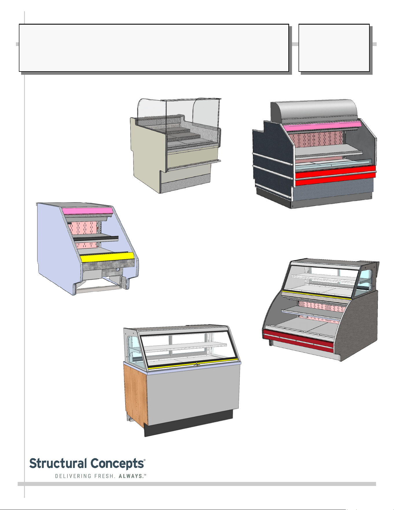
REFRIGERATED SELF-SERVICE SALAD/SANDWICH /BEVERAGE (GRAB-N-GO)
USER MANUALS\20-00045_FUSION_USER MANUAL_GP(L)XXDRLB_GP(L)XXRG_RRLB_REF_GRAB-N-GO_CASE
Model GP540RRLB.5571B
Model CDR5745A
Model GP236DRLB (Front Panel
To Be Attached As Part of Lineup)
Model GP441RG.6122 /
GP441RRC.6122.6527 (With Upper
Display Refrigeration Unit)
SCC P/N
20-00045
USER
MANUAL
FUSION
CAREFULLY FOLLOW THESE INSTRUCTIONS
Structural Concepts Corp. ∙ 888 E. Porter Rd ∙ Muskegon, MI 49441 Phone: 231.798.8888 Fax: 231.798.4960 ∙ www.structuralconcepts.com
Model GP340DRLB.5580
2
TABLE OF CONTENTS / MODELS INCLUDED IN MANUAL
TABLE OF CONTENTS / MODELS INCLUDED IN MANUAL ……………………….…..………………...
OVERVIEW / TYPE / COMPLIANCE / WARNINGS / PRECAUTIONS / WIRING / PLUGS ….….……...
INSTALLATION / SETUP / STARTUP / THERMOMETER / LED & FLUORESCENT LIGHTING /
EVAPORATOR COIL FAN DISCHARGE, ETC………………………………………………………..
INSTALLATION: SKID REMOVAL / ALIGNING CASE / FRAME SUPPORT RAILS ………….………..
CASE START-UP / THERMOMETER FUNCTION & LOCATIONS .………………..……………………...
LED LIGHT REMOVAL/REPLACEMENT, PLUG/CORD POSITIONING, PLUG INSERTION ………….
FLUORESCENT LIGHT REMOVAL/REPLACEMENT …………………………………......……………......
DECKING, EVAPORATOR COIL FAN DISCHARGE, TXV LOCATION ……………………………..........
GENERAL LAYOUT OF VARIOUS MODELS (COMPONENTS) …………………………………………...
MODEL GP236DRLB (DRY TOP UNIT) - REAR PANEL / FIELD ACCESS / TEMP. CONTROLLER ..
MODEL GP236DRLB (DRY TOP UNIT) - LED LIGHTS / THERMOMETER / HONEYCOMB /
EVAPORATOR COIL …………………………………………………………………………………….
MODEL GP441RRC.6122.6527 - ELECTRICAL BOX (FIELD ACCESS / ETHERNET / THERMOSTAT)..
MODEL GP540RRLB.5571B (SIMILAR TO GP440RRLB.5571) - OVERVIEW OF CASE ..………….…
MODEL GP540RRLB.5572C - OVERVIEW OF CASE ………………………..……………………….…….
MODEL CDR5745A (SERVICE CASE ONLY) - OVERVIEW OF CASE ………....…………………….….
MODEL GP441RG.6122 (REFRIGERATED SELF-SERVICE GRAB-N-GO - OVERVIEW OF CASE ...
MODEL GENERIC - OPTIONAL NIGHT AIR CURTAIN INSTALLATION / OPERATING
INSTRUCTIONS ..……………….………..………………………………………………………………
CLEANING SCHEDULE / PREVENTIVE MAINTENANCE / TROUBLESHOOTING …………………….
CLEANING SCHEDULE (TO BE PERFORMED BY STORE PERSONNEL) …...……………….............
PREVENTIVE MAINTENANCE (TO BE PERFORMED BY TRAINED SERVICE PROVIDER) ..……….
TROUBLESHOOTING (TO BE PERFORMED BY STORE PERSONNEL) ……..…………….….……….
TROUBLESHOOTING (TO BE PERFORMED BY TRAINED SERVICE PROVIDERS) ..…………….….
TECHNICAL INFORMATION (THERMOSTAT / SERIAL LABEL / WARRANTY / TECHNICAL
SERVICE INFORMATION, ETC.) ………………………………………………………………………
SERIAL LABEL LOCATION & INFORMATION LISTED / TECH INFO & SERVICE ………………........
PROGRAMMABLE CONTROLLER INFORMATION ………………………………………………………...
TECHNICAL SERVICE CONTACT INFORMATION / WARRANTY INFORMATION …………………..
2
3-4
5
6
7
8
9
10
11
12
13
14
15-18
19
20-24
25-26
27
28
29-32
33-34
35
36
37
38
39
40
3
OVERVIEW
• These Structural Concepts cases are designed to
merchandise packaged products at 41 °F (5 °C) or less
product temperatures (unless custom cases with wire
rack shelving).
• Product must be pre-chilled to 41 °F (5 °C) or less before
being placed in merchandiser.
• Cases should be installed and operated according to this
operating manual’s instructions to ensure proper
performance. Improper use will void warranty.
NSF/ANSI TYPE I vs. II ENVIRONMENTAL CONDITIONS
This unit is designed for the display of products in ambient
environmental conditions where temperatures and relative
humidity are maintained within a specific range.
•
NSF/ANSI Type I Conditions: Product is displayed in
store conditions with maximum ambient temperature of
75 °F (24 °C) and maximum relative humidity of 55%.
•
NSF/ANSI Type II Conditions: Product is displayed in
store conditions with maximum ambient temperature of
80 °F (27 °C) and maximum relative humidity of 55%.
• If you are unsure if your unit is classified as NSF/ANSI
Type I or Type II, see tag next to serial label on your case.
COMPLIANCE
• Performance issues when in violation of applicable
NEC, federal, state and local electrical and plumbing
codes are not covered by warranty.
• See below compliance guideline.
WARNINGS
• This page contains important warnings to prevent injury or
death. Please read carefully!
PRECAUTIONS and WIRING DIAGRAMS
• See next page for PRECAUTIONS and WIRING
DIAGRAM information.
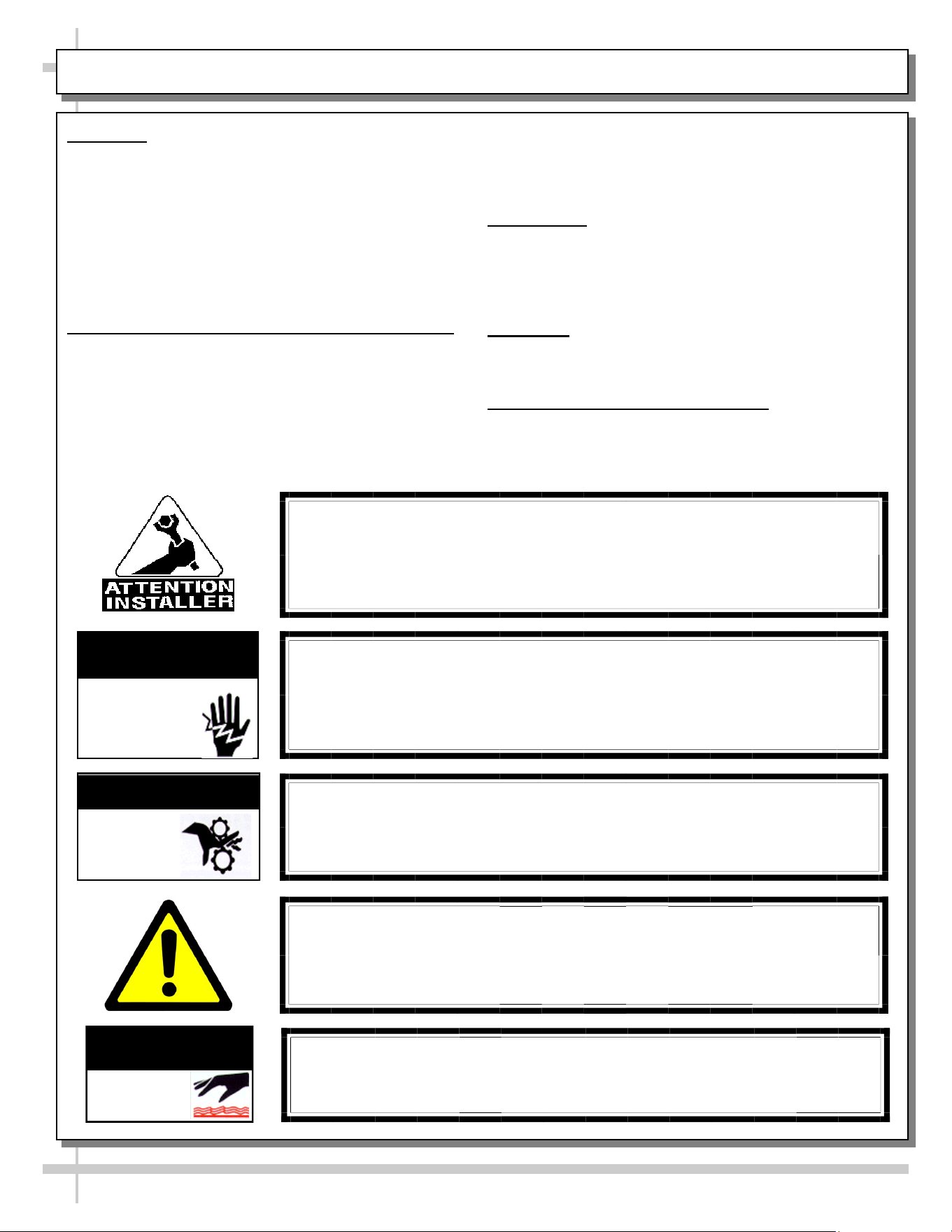
WARNING
Hazardous moving parts. Do not operate unit with covers removed.
Fan blades may be exposed when deck panel is removed.
Disconnect power before removing deck panel.
WARNING
Risk of electric shock. Disconnect power before servicing unit.
CAUTION! More than one source of electrical supply is
employed with units that have separate circuits.
Disconnect ALL ELECTRICAL SOURCES before servicing.
WARNING
ELECTRICAL
HAZARD
WARNING
KEEP
HANDS
CLEAR
COMPLIANCE
This equipment MUST be installed in compliance with
all applicable NEC, federal, state and local
electrical and plumbing codes.
OVERVIEW / TYPE / COMPLIANCE / WARNINGS / PRECAUTIONS / CORDS / WIRING - PAGE 1 of 2
WARNING
This product can expose you to chemicals, including
Urethane (Ethyl Carbamate), which are known to the state of
California to cause cancer and birth defects or other reproductive
harm. For more information go to P65Warnings.ca.gov.
WARNING
Condensate pan and overflow condensate pans are HOT!
Disconnect and allow to cool before cleaning or removing from case.
WARNING
HOT
SURFACE
PRECAUTIONS
• Following are important precautions to prevent damage
to unit or merchandise. Read carefully!
• See previous page for specifics on OVERVIEW,
CONDITION TYPE, COMPLIANCE and WARNINGS.
WIRING DIAGRAM
• Each case has its own wiring diagram folded and in its
own packet. It may be placed near ballast box, field
wiring box, raceway cover, or other related location.
REFRIGERANT DISCLOSURE STATEMENT
• This equipment is prohibited from use in California with
any refrigerants on the “List of Prohibited Substances” for
that specific end-use, in accordance with California Code
of Regulations, title 17, section 95374.
• This disclosure statement has been reviewed and
approved by Structural Concepts and Structural Concepts
attests, under penalty of perjury, that these statements
are true and accurate.
OVERVIEW / TYPE / COMPLIANCE / WARNINGS / PRECAUTIONS / CORDS / WIRING - PAGE 2 of 2
4
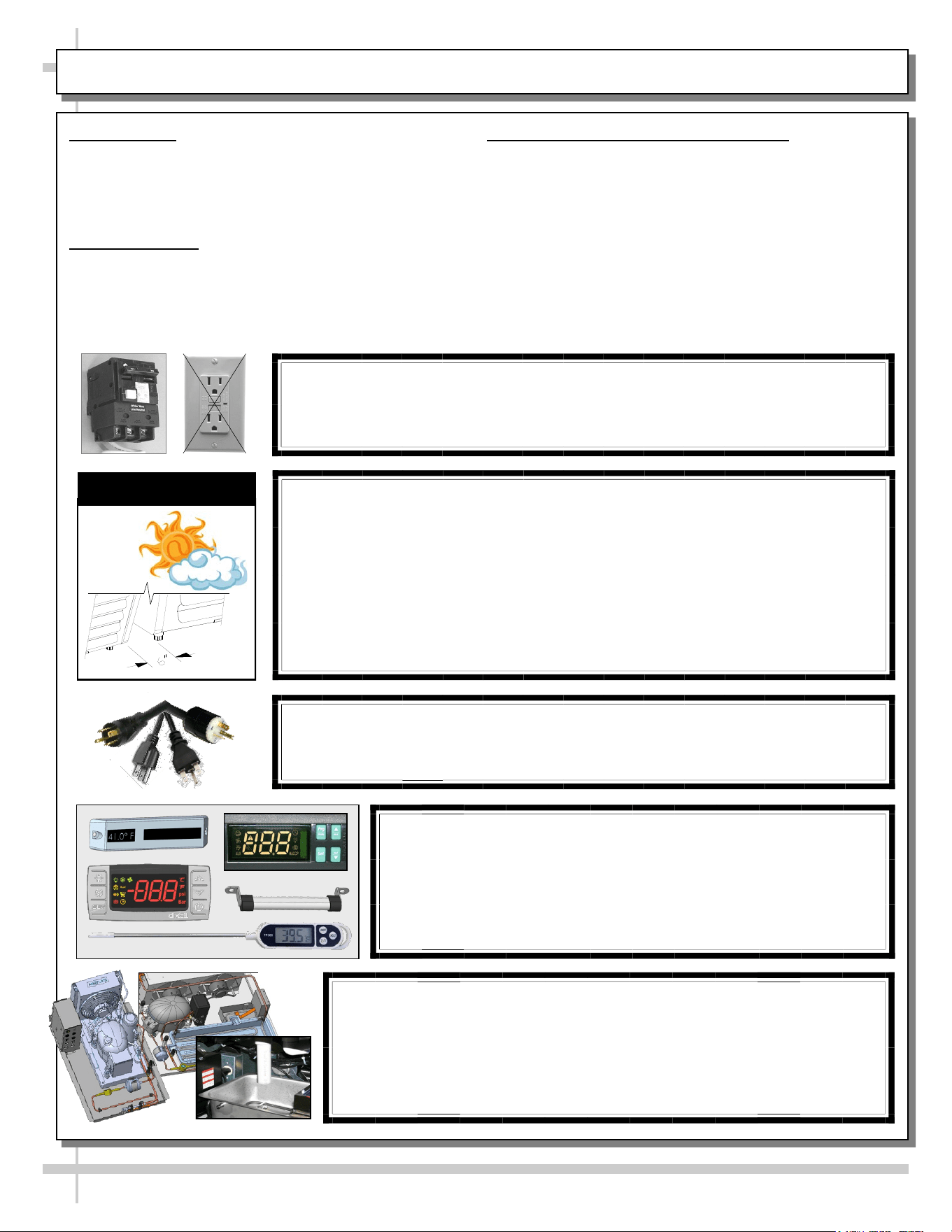
CAUTION! POWER CORD AND PLUG MAINTENANCE
Risk of electric shock. If cord or plug becomes damaged,
replace only with cord and plug of same type.
CAUTION! GFCI BREAKER REQUIREMENT
If N.E.C. (National Electric Code) or your local code
requires GFCI (Ground Fault Circuit Interrupter) protection,
you MUST use a GFCI breaker in lieu of a GFCI receptacle.
CAUTION! ADVERSE CONDITIONS / SPACING ISSUES
• Performance issues caused by adverse conditions are NOT warranted.
• To prevent damage to end panels due to condensation, apply industrial grade
silicone sealant and tightly join to opposite end panels. When not adjoining
cases, keep end panels at least 6” away from walls/structures. Rear panels
must also be kept at least 6” from walls and structures.
• Case must not be exposed to direct sunlight or any heat source.
• To maintain proper case temperature, keep case at least 15-feet from exterior
doors, overhead HVAC vents or any air curtain disruption.
• Self-contained case clearance: 6” min. air intake / 6” min. air discharge.
CAUTION
CAUTION! DO NOT RELY ON THERMOMETERS OR
THERMOSTATS FOR PRODUCT (FOOD) TEMPERATURES.
• Thermometers & thermostats reflect air temperatures ONLY.
• For ACTUAL product (food) temperatures, use a calibrated food
probe thermometers ONLY.
• For accurate readings, DO NOT use infrared food thermometers.
CAUTION! CHECK CONDENSATE PAN, ITS POSITION & PLUG!
Water on flooring can cause extensive damage!
• Before powering up case, check that condensate pan is positioned
directly under case’s condensate drain.
• Before powering up case, check that condensate pan’s electrical plug is
SECURELY connected to condensate system’s receptacle.
• If wicking material is used in condensate pan, check that it is secure.

5
INSTALLATION / SETUP / STARTUP / THERMOMETER / LIGHTING / EVAP. COIL FAN DISCHARGE, ETC.
INSTALLATION /
SETUP / STARTUP /
THERMOMETER /
LIGHTING /
EVAPORATOR COIL
FAN DISCHARGE,
TXV LOCATION, ETC.
6
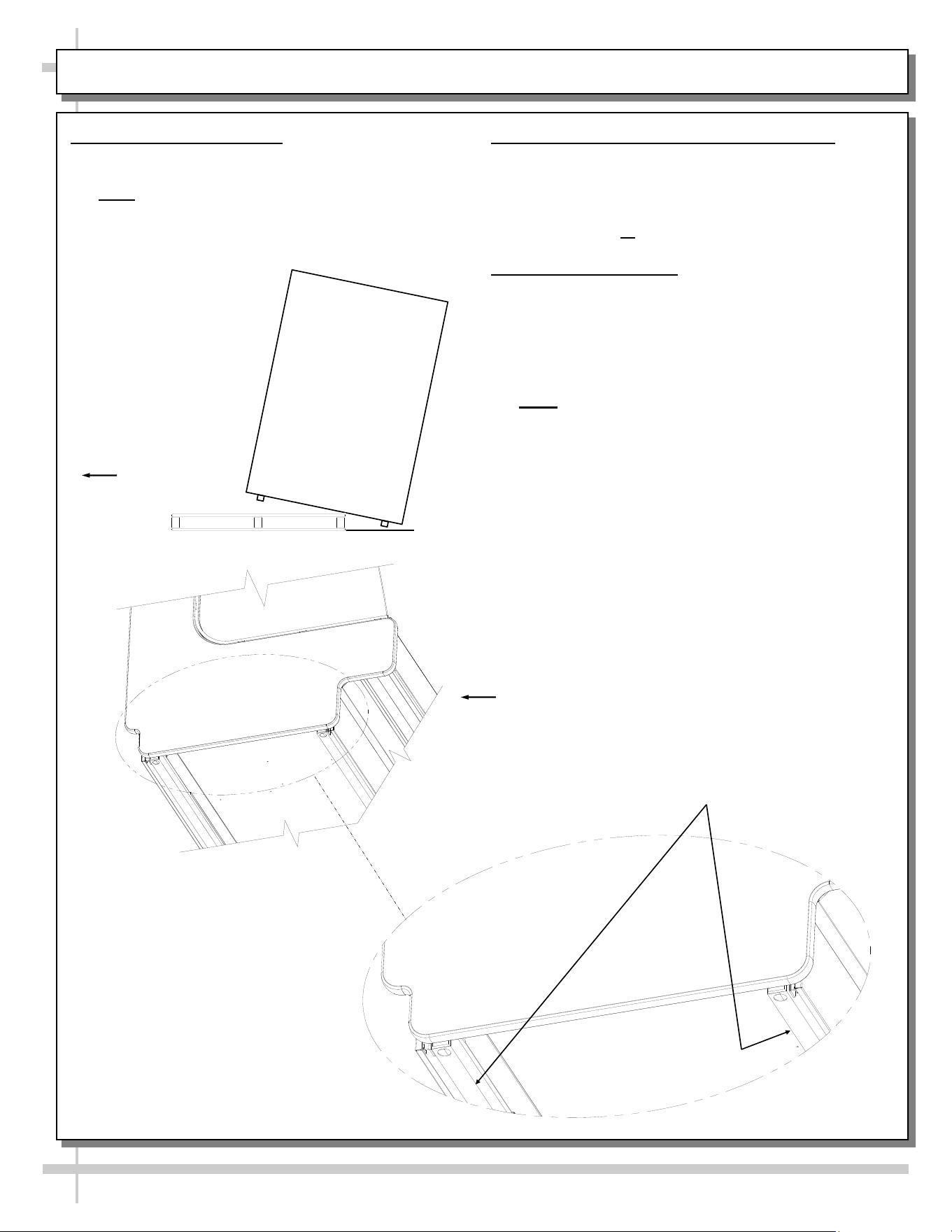
INSTALLATION: SKID REMOVAL / ALIGNING CASE / FRAME SUPPORT RAILS
1. Remove Unit From Skid
• Caution! To prevent damage, support case
while sliding skid out from under case.
• Note: Illustration below reflects general outline of
sample case and does not reflect any particular
model or options).
Carefully Slide
Skid Out From
Under Unit
2. Position & Align Case Alongside Others
• Before adjusting levelers, make certain that the
case is in proper position and, if required, aligned
with adjoining case(s).
• This may require repositioning of the case you
are installing or the already positioned case.
3. Frame Support Rails
• Illustration below shows case with frame support
rails (sample case - may not exactly reflect your
particular model).
• Shims will be provided with all cases that have
frame support rails.
• Use shims to level case.
• Note: After case is in position, it must be
sealed to floor to prevent entry or leakage of
liquid or moisture.
Case
Front
Frame
Support Rails
7
CASE START-UP / THERMOMETER FUNCTION & LOCATION
1. Case Start-Up
• Case will energize when properly field-wired.
• Refrigeration system will supply cold air to rear
drawers, rear door compartment and front grab-n
-go section upon being energized.
• Front refrigerated section shown below. Light
switch (if any) will turn on light at front of case.
• When properly field-wired, coil fans should turn
on. From inside of the case, check for discharge
air from the air diffusing honeycomb to confirm
that fans are functioning properly. See next
page for honeycomb location.
Thermometer to
Refrigerated Front
Grab-N-Go Section
• When case is in start-up mode (or has been idle
for a long period of time), unit requires 75
minutes of run time to pull-down temperature.
2. Thermometer Function & Placement
• A. Thermometers may provides temperature to
separate areas in the case.
• B. Thermometers reflect warmest air
temperature in merchandiser. They do not
provide actual food temperature.
• C. Use probe thermometers to determine
actual product temperatures.
8
LED LIGHT REMOVAL/REPLACEMENT, PLUG/CORD POSITIONING, PROPER PLUG INSERTION
Light Switch
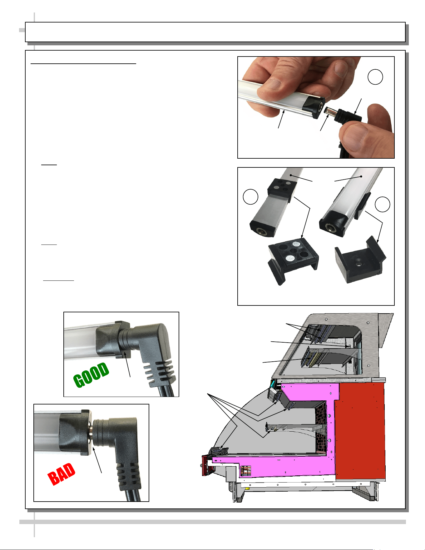
1. LED Style Light Fixtures
Removal of Faulty LED Lights:
• Contact Structural Concepts’ Technical Service
Department for replacement LED lights.
• Turn off LED light switch.
• To remove faulty LED light, follow these steps:
A. Disconnect plug from LED light.
B. Using both hands, grasp LED light assembly (with its
magnetic mounting clips). Pull downward and off its
shelf (or header).
C. Remove magnetic mounting clips from LED light by
pressing against flange part of clip with thumb.
>> Note: Mounting clips MAY be riveted to shelf or header.
In such instances, simply remove LED light from mounting
clips by pressing against flange part of clips with thumb.
Replacement of LED lights:
• Attach magnetic mounting clips onto LED light.
• Adjust magnetic mounting clips so they are equally
spaced on LED light.
• Reattach LED light assembly to its shelf/header.
• Position properly in shelf/header.
>> Note: If mounting clips are riveted to shelf (or header),
attach by placing LED in base of clip and then snapping into
clip at FLANGE SIDE.
• Press plug’s barrel-shaped insert deep into LED light.
• Important: If plug is not inserted ALL THE WAY IN the
LED light’s orifice, the light may not energize. See
“BAD” vs. “GOOD” insertion illustrations below-right.
• Turn LED light switch back on.
Magnetic Mounting
Clip View #2
LED
Lights
B
A
Plug
Barrel
Shaped
Insert
LED
Light
C
Magnetic Mounting
Clip View #1
No Gap
Gap
LED Lights
LED Lights
LED Lights
Note: Illustrations Shown May Not
Reflect Every Feature or Option of
Your Particular Case.
9
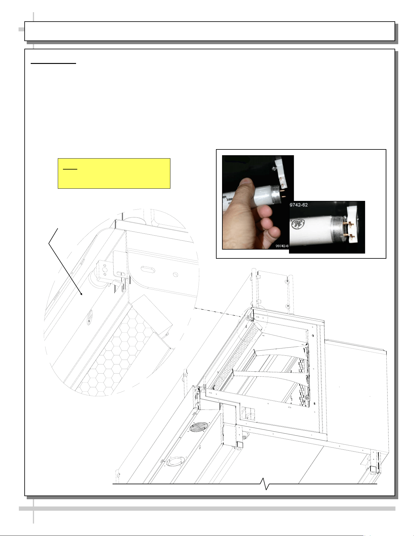
FLUORESCENT LIGHT REMOVAL/REPLACEMENT (FLUORESCENTS ONLY)
Fluorescent
Light
Installation of lamp:
• Align pins with slot.
• Insert pins into socket by rotating the bulb
1/4-turn to secure either the (upper or lower)
pinned contacts into the sockets.
• Rotate the remaining bulb contacts (1/4 turn)
into the remaining lamp mounting socket
contacts.
• See illustration below.
Light Fixture
Removal of lamp:
• Rotate lamp (1/4-turn) either direction to disengage
(upper or lower) pins/contacts from lamp mounting
sockets.
• Remove bulb by applying even pressure from the
back side at the bulb ends and pulling the
remaining contact from the sockets.
• See illustration at below-left.
Standard
Fluorescent
Light Fixtures
10
TXV Evaporator
Coils
Evap. Fan (Typ.)
Evap. Fan Shroud
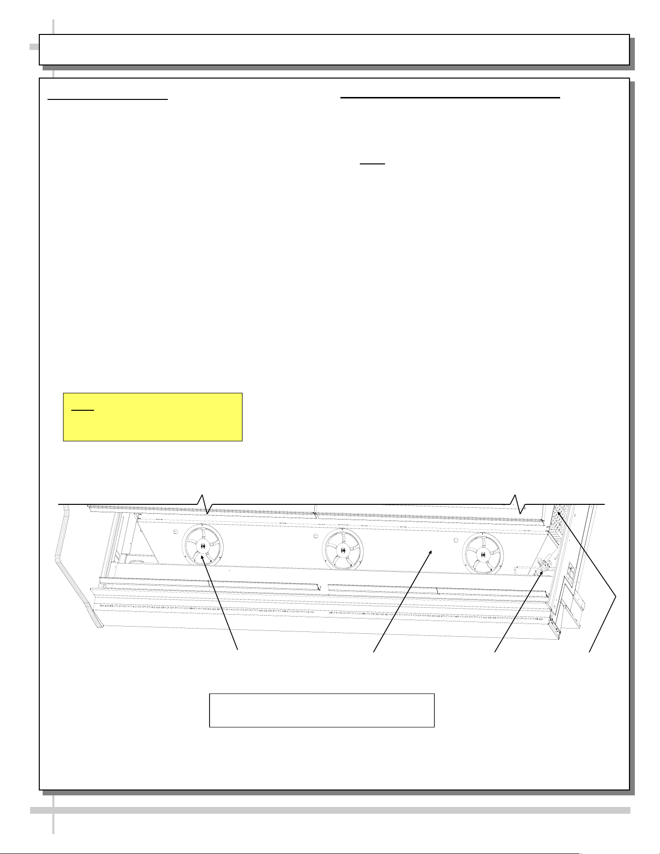
1. Coil Fan Discharge
When Main Power Switch is turned on, refrigeration
section will energize (see CASE START-UP section
in this manual).
• Evaporator coil fans should turn on. From inside
of the case, check for discharge air from fans to
confirm that they are functioning properly.
• When the case is in a start up mode or has been
idle for a long period of time, the unit will require
75 minutes of run time to pull-down
temperature.
• See below illustration.
2. TXV (Thermostatic Expansion Valve)
• TXV is under access panel (at customer
front-right of case).
• Decking must be removed for access.
• See illustration below for location.
• Note: Partially disassembled view below shown
for illustrative purposes only.
DECKING, EVAPORATOR COIL FAN DISCHARGE, TXV LOCATION
View of Case With Decking and End Panel
Removed for Illustrative Purposes Only
Note: Illustrations Shown May Not
Reflect Every Feature or Option of
Your Particular Case.

11
GENERAL LAYOUT OF VARIOUS MODELS (COMPONENTS)
GENERAL LAYOUT OF
VARIOUS MODELS
(WIDE RANGE OF
COMPONENTS,
THERMOSTATS,
THERMOSTAT PROBES,
ELECTRICAL BOXES,
TRANSFORMERS,
THERMOMETER, FIELD
SENSORS, SCALE
STANDS, CAT-5 ETC.)
12
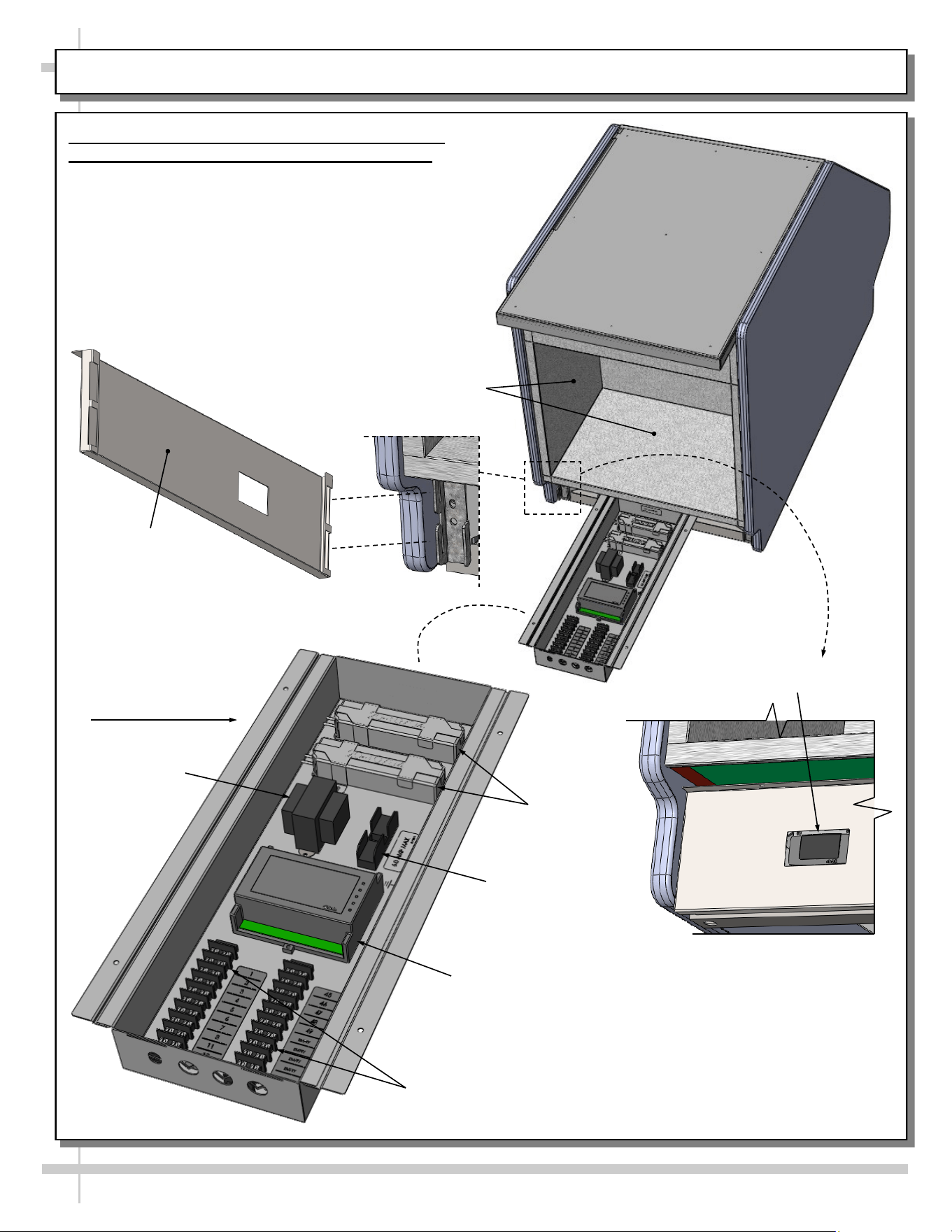
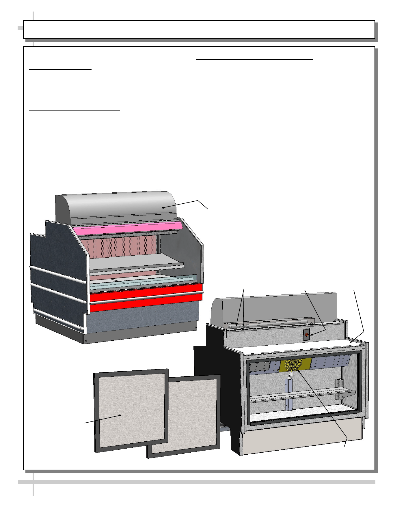
MODEL GP236DRLB (DRY TOP UNIT) - REAR PANEL / FIELD ACCESS BOX / TEMP. CONTROLLER
Model GP236DRLB Rear Panel / Field Access /
Temperature Controller (Customer Provided)
Illustration below shows general layout.
• Rear storage area is open with no shelving.
• Rear panel may be removed without screws (slot
to hook configuration).
• Field access box components are viewable by
removal of cover (for illustrative purposes only).
• Dixell® controller is customer maintained. See
your store manager for operational specifics.
Fuse Block
Terminal
Blocks
LED
Dixell® Controller
Transformer
Dixell® Display
View of Rear Panel
Attached To Case
Rear Panel
(Removable)
Field Access Box /
Electrical Box
Rear Storage
Area (Open)
13
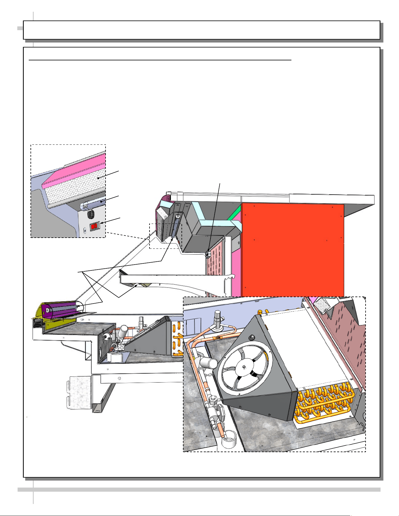
MODEL GP236DRLB (DRY TOP UNIT) - LED LIGHTS / THERMOMETER / HONEYCOMB / EVAP. COIL
Model GP236DRLB LED Lights / Thermometer / Honeycomb / Evaporator Coil
Illustration below is shown with end panel and deck pan removed for illustrative purposes only.
• LED lights are at nose, shelf and upper section (behind honeycomb).
• Light switch is at upper left below thermometer.
• Thermometer reflects warmest air temperature in merchandiser. They do not reflect actual food
temperature. Use probe thermometers to determine actual product temperatures.
• See MAINTENANCE FUNDAMENTALS - HONEYCOMB AIR DIFFUSERS section in this operating
manual for honeycomb cleaning specifics.
• Evaporator coil layout is shown rotated for layout purposes.
LED Lights
Honeycomb
Thermometer
Evaporator Coil Layout
(Rotated For Viewing Purposes Only)
LED
Light
LED Light / Honeycomb
(Rotated View)
Light
Switch
14
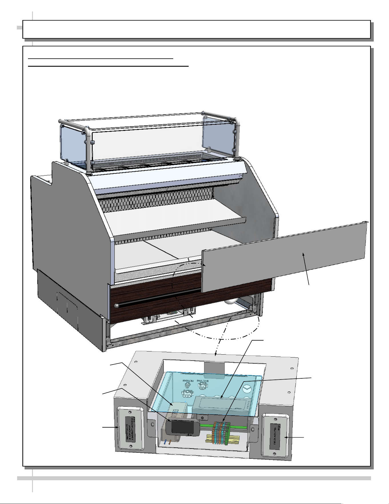
MODEL GP441RRC.6122.6527 - ELECTRICAL BOX (FIELD ACCESS / ETHERNET / THERMOSTAT, ETC.)
Model GP441RRC.6122.6527 Electrical/Field
Access / Ethernet Access Box / Thermostat, Etc.
Illustration below shows general layout.
• Front toe-kick (held in place with magnets) may
be removed by simply lifting up and off.
• Electrical box contains wide range of electrical
components .
• Electrical box may be slid outward (toward front of
case) to access electrical components.
• Dixell® controller is customer maintained. See
your store manager for operational specifics.
Field
Access Box
Terminal
Block
LED Driver
Dixell®
Thermostat
Front Toe-Kick
Receptacle & Optional
Ethernet Access Box
Dixell® Controller
15
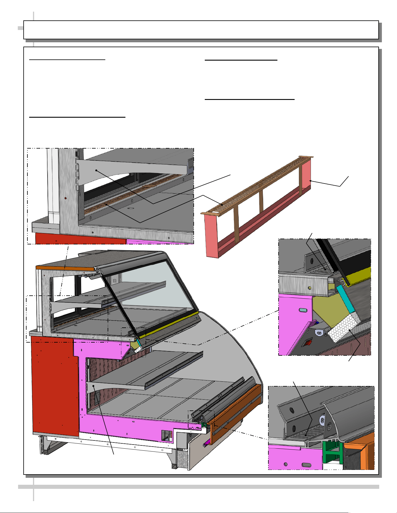
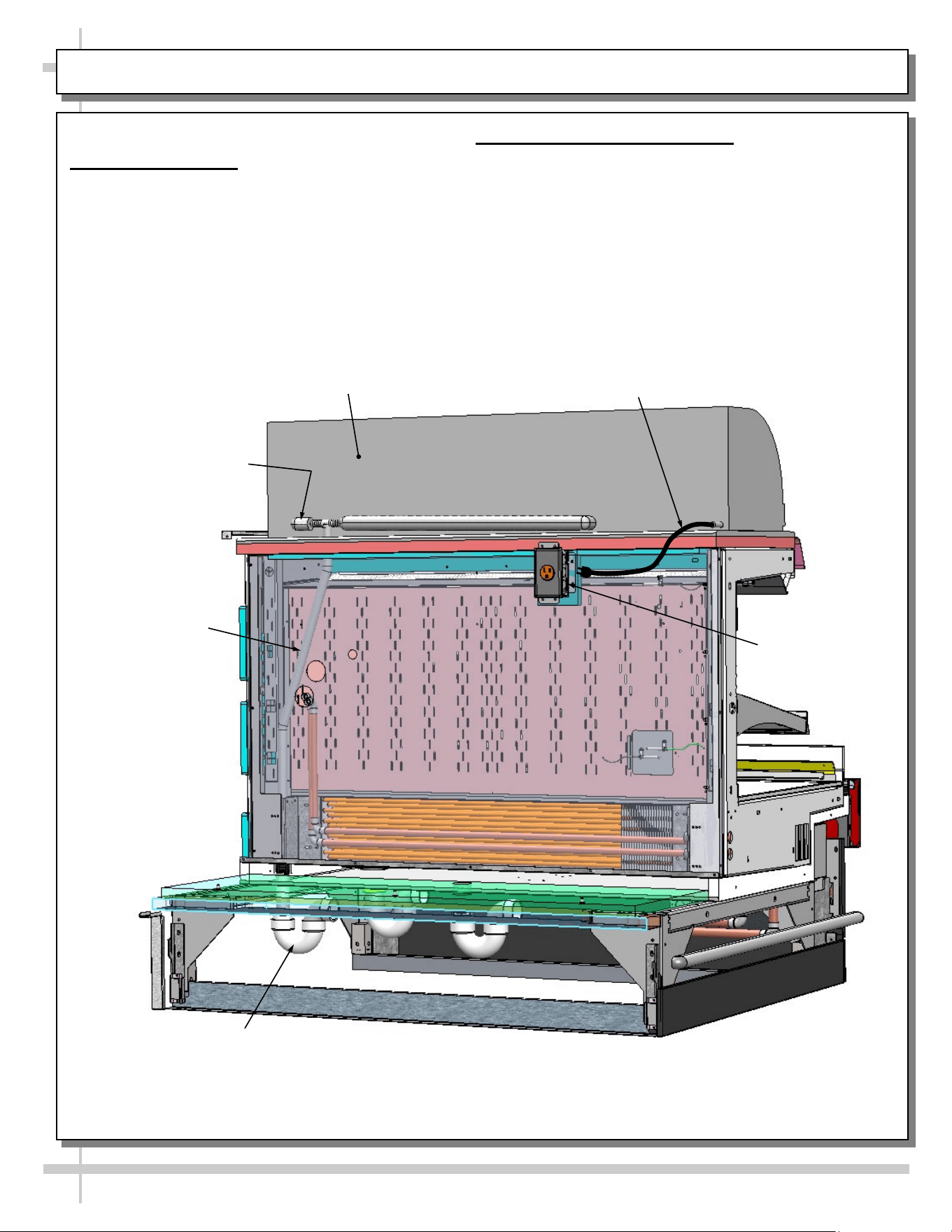
MODEL GP540RRLB.5571B (SIMILAR TO GP440RRLB.5571) - OVERVIEW OF CASE FRONT
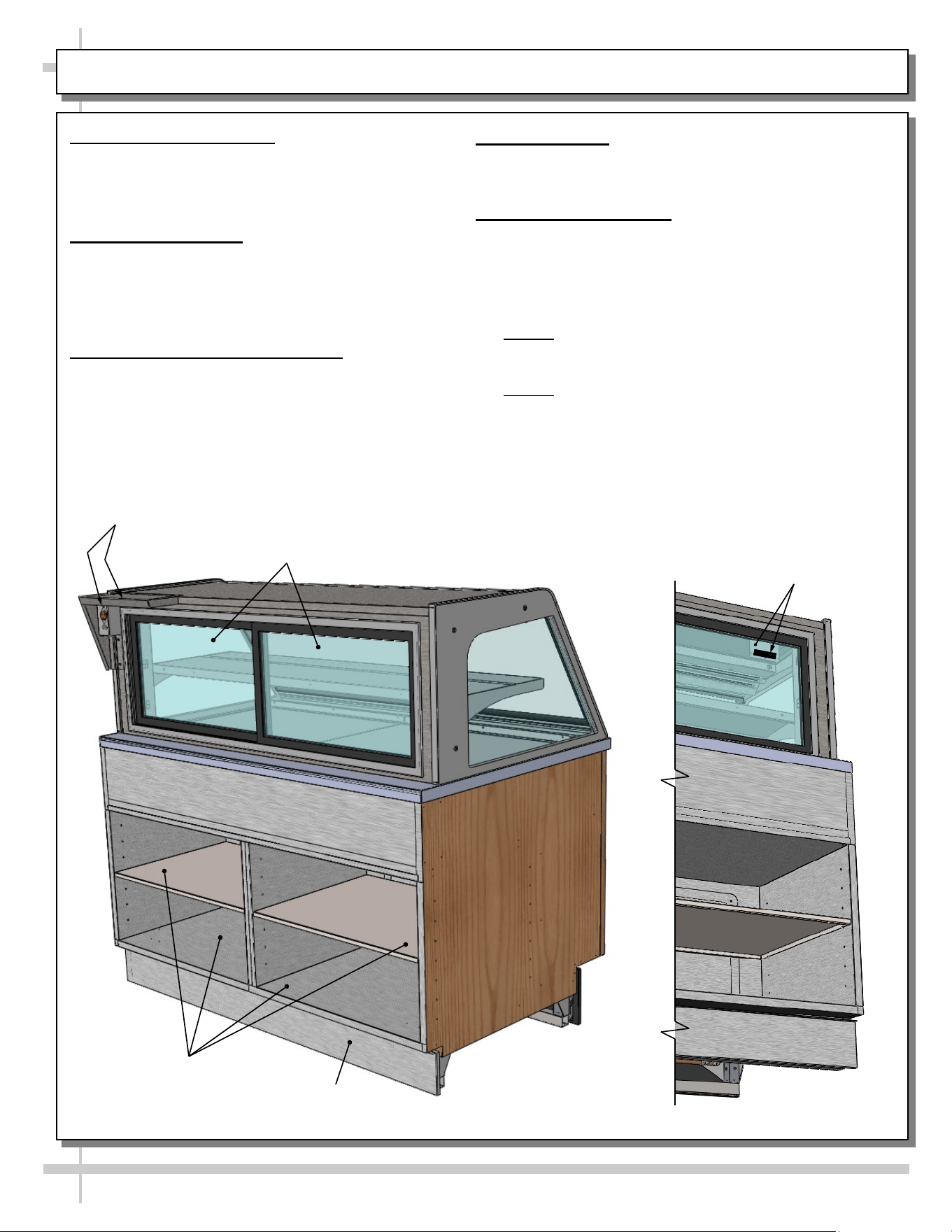
1. Thermometer Probe Location - Front Section
View below shows location of probe plate.
• Probe is positioned behind protective plate.
• See approximate location in illustration below.
• Thermometer probe is attached by spacer and
screw assembly.
• Spacer allows probe to garner accurate
temperature readings and transmit to
thermometer.
Honeycomb
Air Diffuser
Rear Plenum
Lower
Refrigerated Section
Light Switch
2. Thermometer
• Thermometer is located at front-right (as shown in
illustration below)
• Note 1: Thermometers reflect warmest air
temperature in merchandiser. They do not
provide actual food temperature.
• Note 2: Use probe thermometers to determine
actual product temperatures.
Thermometer
Probe Plate
Thermometer
16
MODEL GP540RRLB.5571B (SIMILAR TO GP440RRLB.5571) - OVERVIEW OF CASE REAR
1. Scale Stand and Outlet
• Scale stand and outlet provides support and
electrical means for scale.
• Caution! Use only approved plug for outlet.
2. Rear Sliding Doors
• Rear sliding doors are removable for cleaning
and/or serving.
Rear
Toe-Kick
Rear Storage
Area
• Use care when removing from case to prevent glass
breakage.
3. Rear Storage Area
• Rear storage area may be used for storing store
supplies.
• See cleaning section in manual.
4. Rear Toe-Kick
• Rear toe-kick may be removed by lifting up and off.
• No screw removal is required.
Scale Stand &
Outlet
Rear Sliding
Doors
17
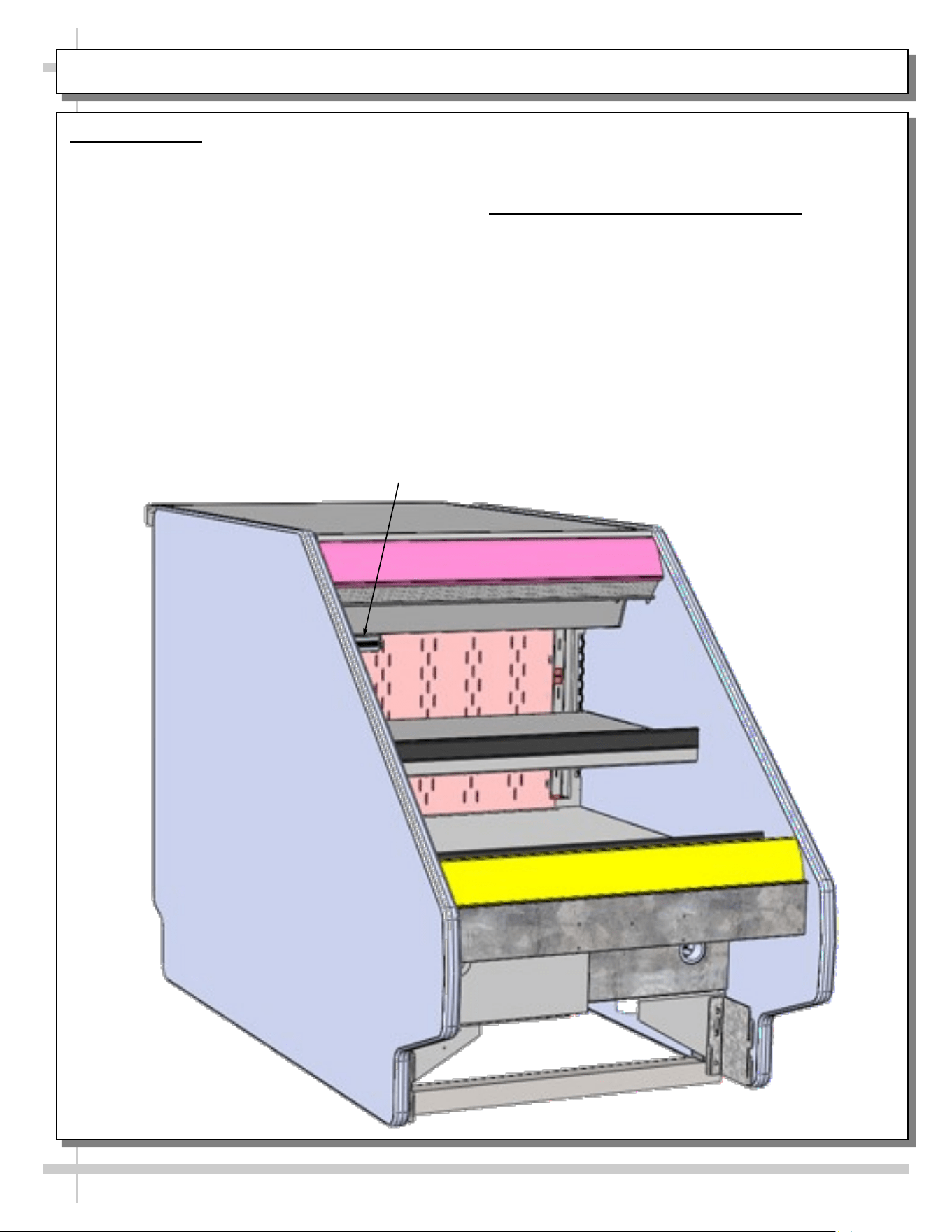
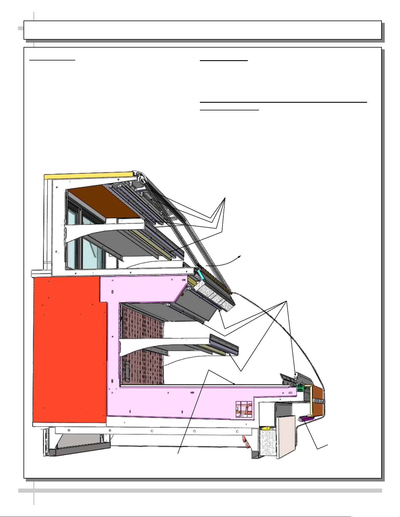
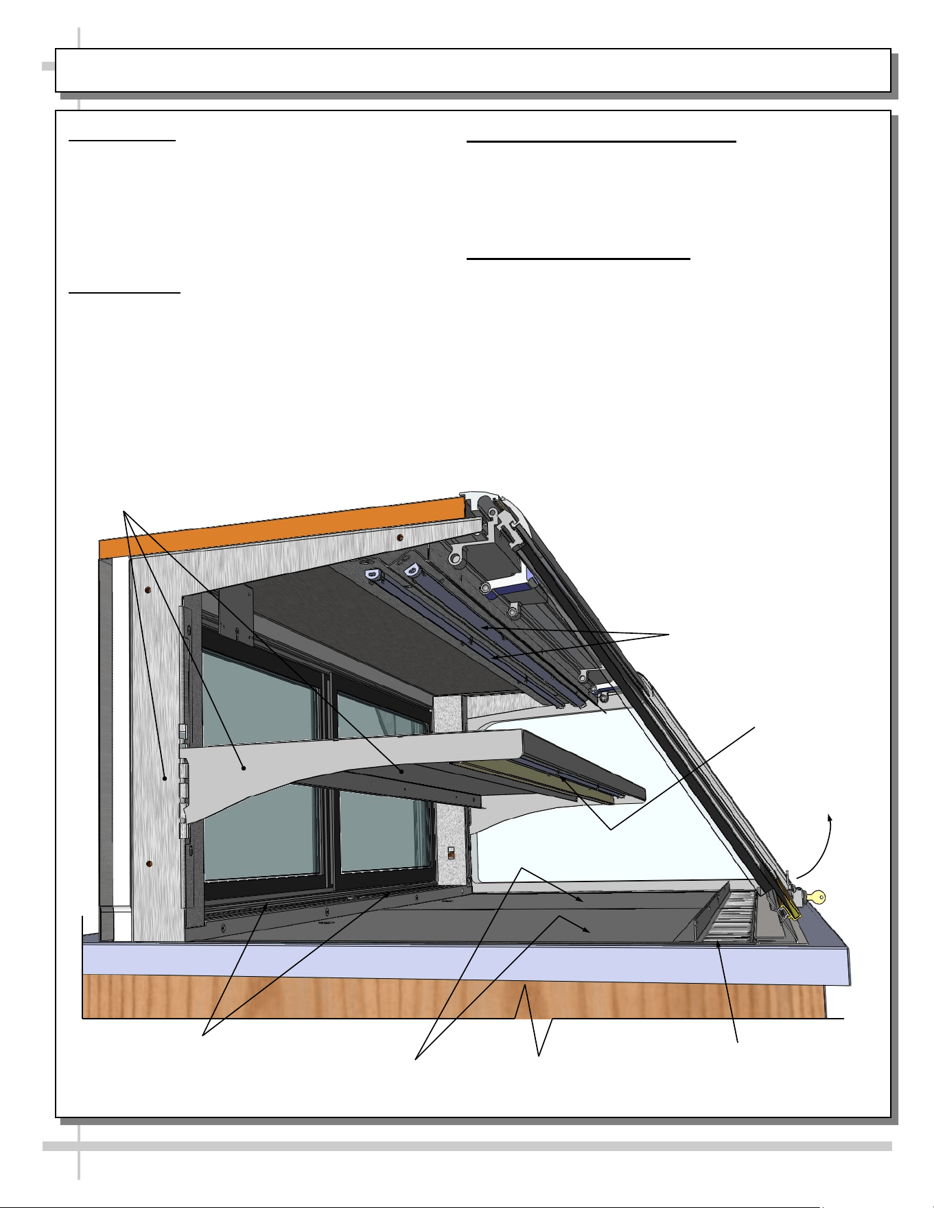
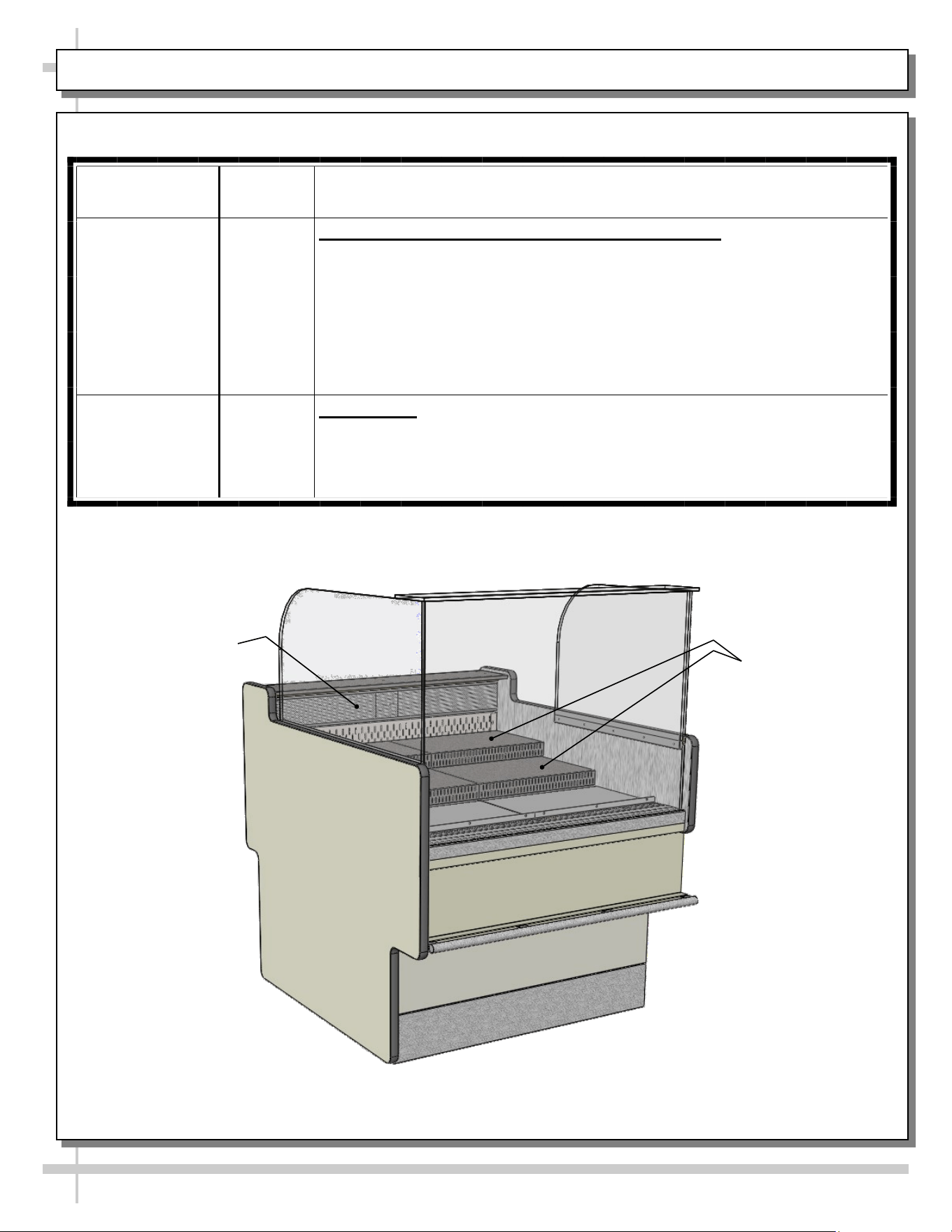
MODEL GP540RRLB.5571B - SHELVING / CRUMB TRAY / DECKING AIR RETURN / HONEYCOMB
1. Adjustable Shelving
• Upper shelving can be tipped downward either 5°
or 10° for display purposes.
• Lower shelving may either be tipped downward
OR raised or lowered (by simply removing and
placing in notches above or below.
2. Air Discharge/Crumb Tray
• Air discharge crumb tray can be lifted up and out
to empty crumbs and residue.
3. Decking/Air Return
• Decking/Air return must remain free from product.
• Do not place product on this area as it will prevent
proper airflow and prevent proper cooling of case.
4. Honeycomb Air Diffuser
• Honeycomb air diffuser can be removed for
cleaning and/or replacement.
• See MAINTENANCE FUNDAMENTALS -
HONEYCOMB AIR DIFFUSERS (SERVICE
TECHNICIANS ONLY) section in this manual.
Air Discharge /
Crumb Tray
Decking / Air
Return
Honeycomb
Air Diffuser
Air Return
Upper Section
Adjustable Shelving
Lower Section
Adjustable Shelving
18
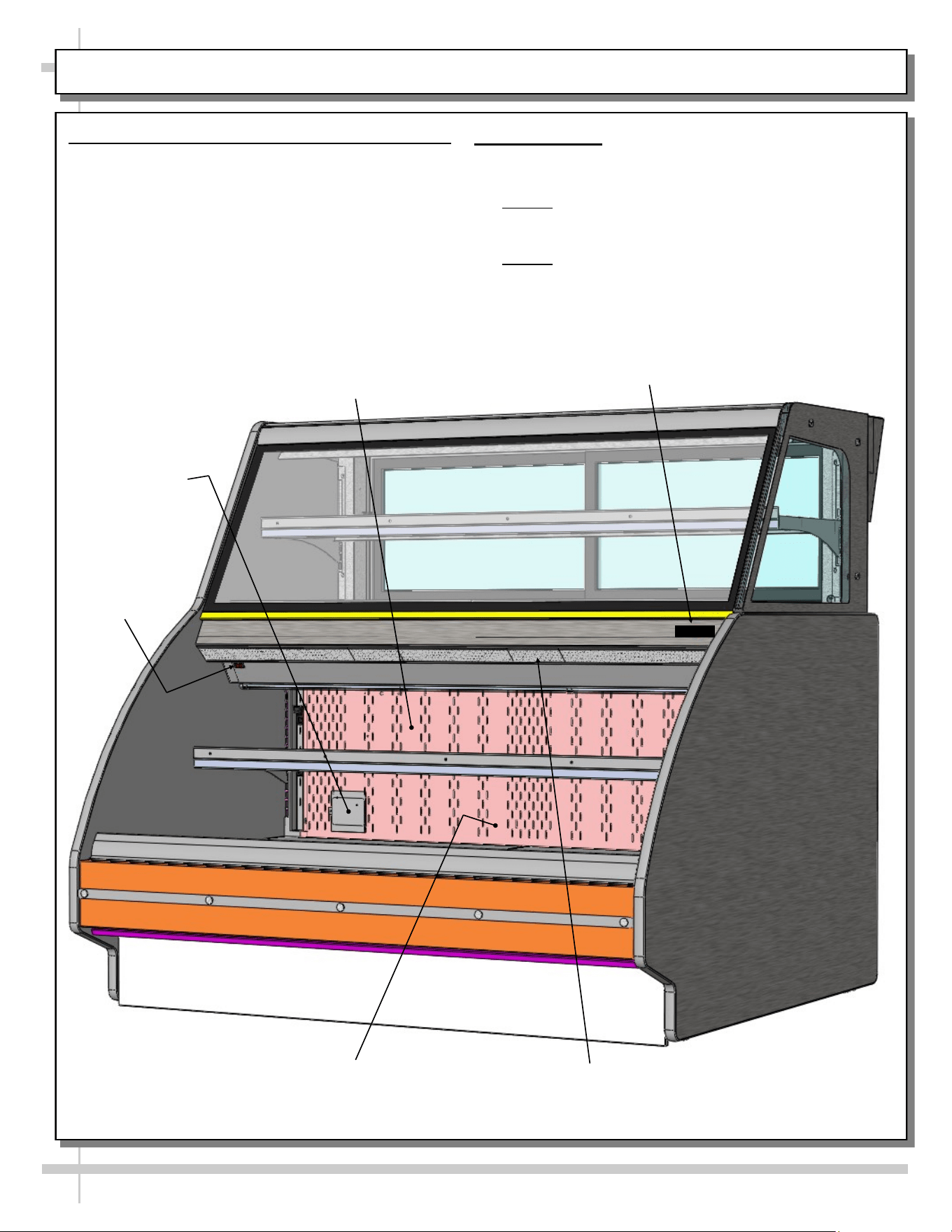
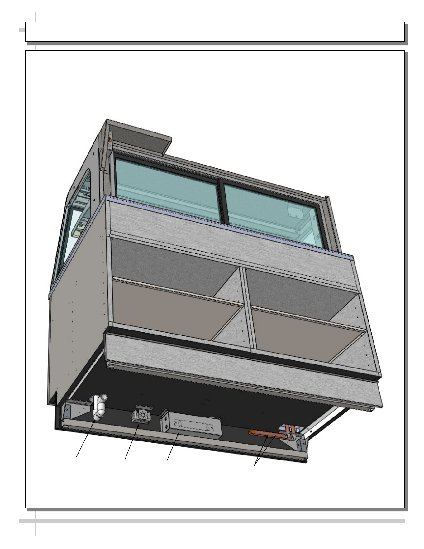
MODEL GP540RRLB.5571B - LED LIGHTING LAYOUT / FRONT GLASS / EVAP. COIL/TXV/FANS, ETC.
1. LED Lights
• Model GP540RRLB.5571B has LED lights only
(no fluorescent lights).
• Lights may be removed for servicing and/or re-
placement.
• See LED LIGHT REMOVAL/REPLACEMENT,
PLUG/CORD POSITIONING, PROPER PLUG
INSERTION section in manual for specifics on
care and maintenance.
2. Front Glass
• Caution! Only authorized service personnel are to
access front glass!
• Front glass may be raised for cleaning or servicing.
3. Evaporator Coil, TXV (Thermostatic Expansion
Valve), Fans, Etc.
• Caution! Only authorized service personnel are to
access area under deck!
• Rotating fans can cause injury!
Upper Section
LED Lights
Lower Section
LED Lights
Lower Skirt
LED Light
Front Glass
(May Be Raised)
Evaporator Coil, TXV, Fans, Etc.
(Under Decking)
19
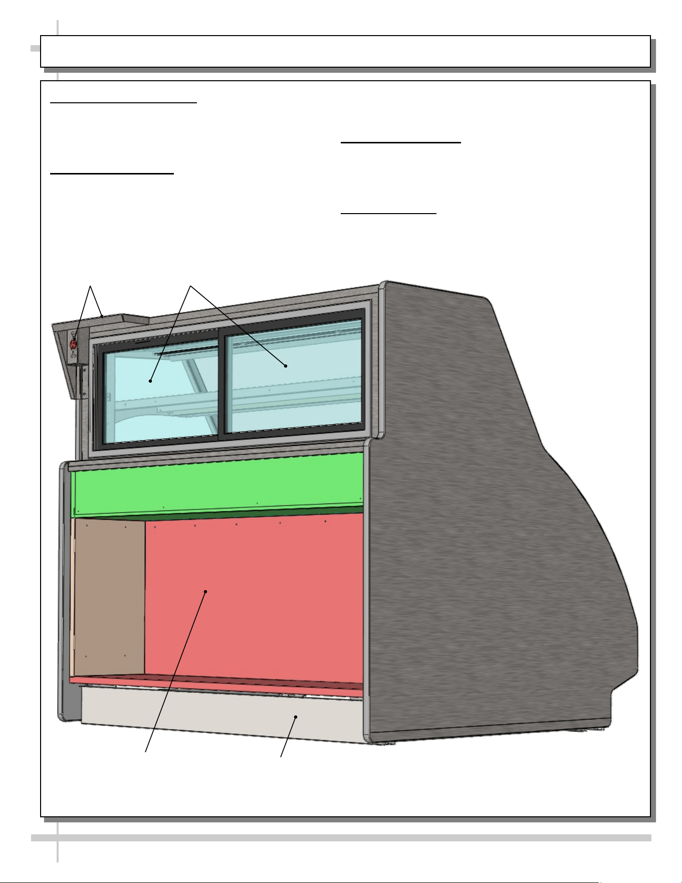
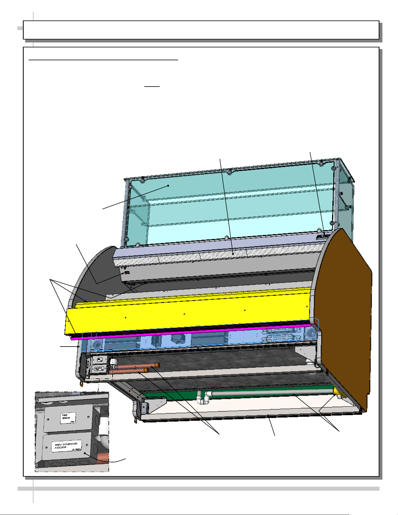
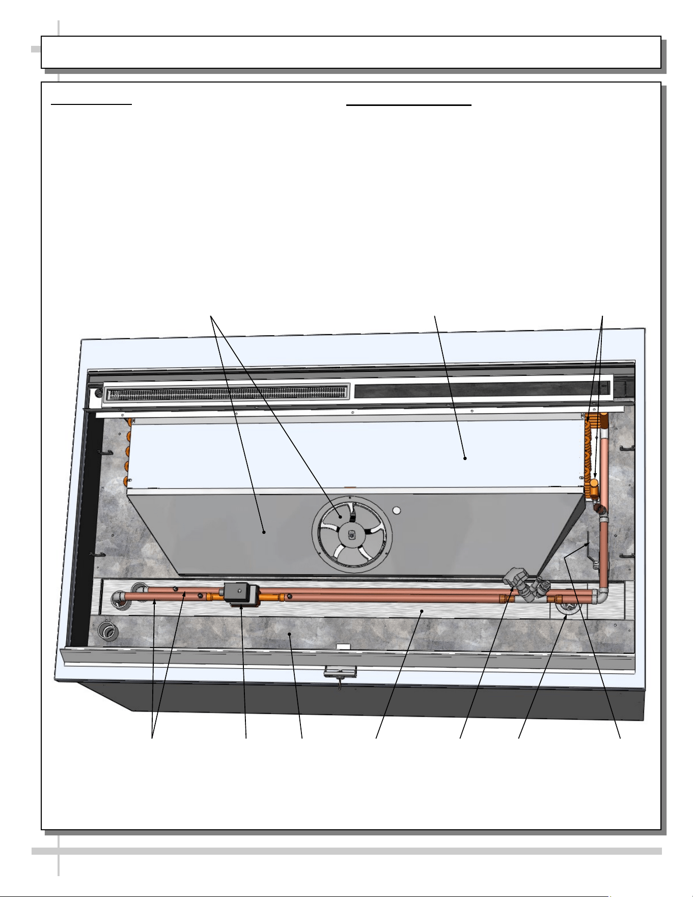
MODEL GP540RRLB.5572C - OVERVIEW OF CASE
Model GP540RRLB.5572C Overview of Case
View below shows general layout of:
• Glass upper sneeze guard (and its glass shelf)
• Thermometer for upper section. Note: Lower
section thermometer is located on rear plenum.
• Probe (positioned behind protective plate on
rear plenum).
Honeycomb
Air Diffuser
Glass Upper Sneeze
Guard With Shelf
Drain Route (From
Upper and Lower
Sections To
Floor Drain)
Light Switch
• Light switch (located at front-left, just below
honeycomb).
• Frame support rails.
• Field sensor box.
• 208V solenoid access box.
• Floor drain (from both upper and lower sections).
• Electrical raceway.
• Refrigeration lines.
Thermometer
Field Sensor / 208V
Solenoid Access
Frame
Support Rails
Refrigeration
Lines
Electrical
Raceway
Electrical
Raceway
20
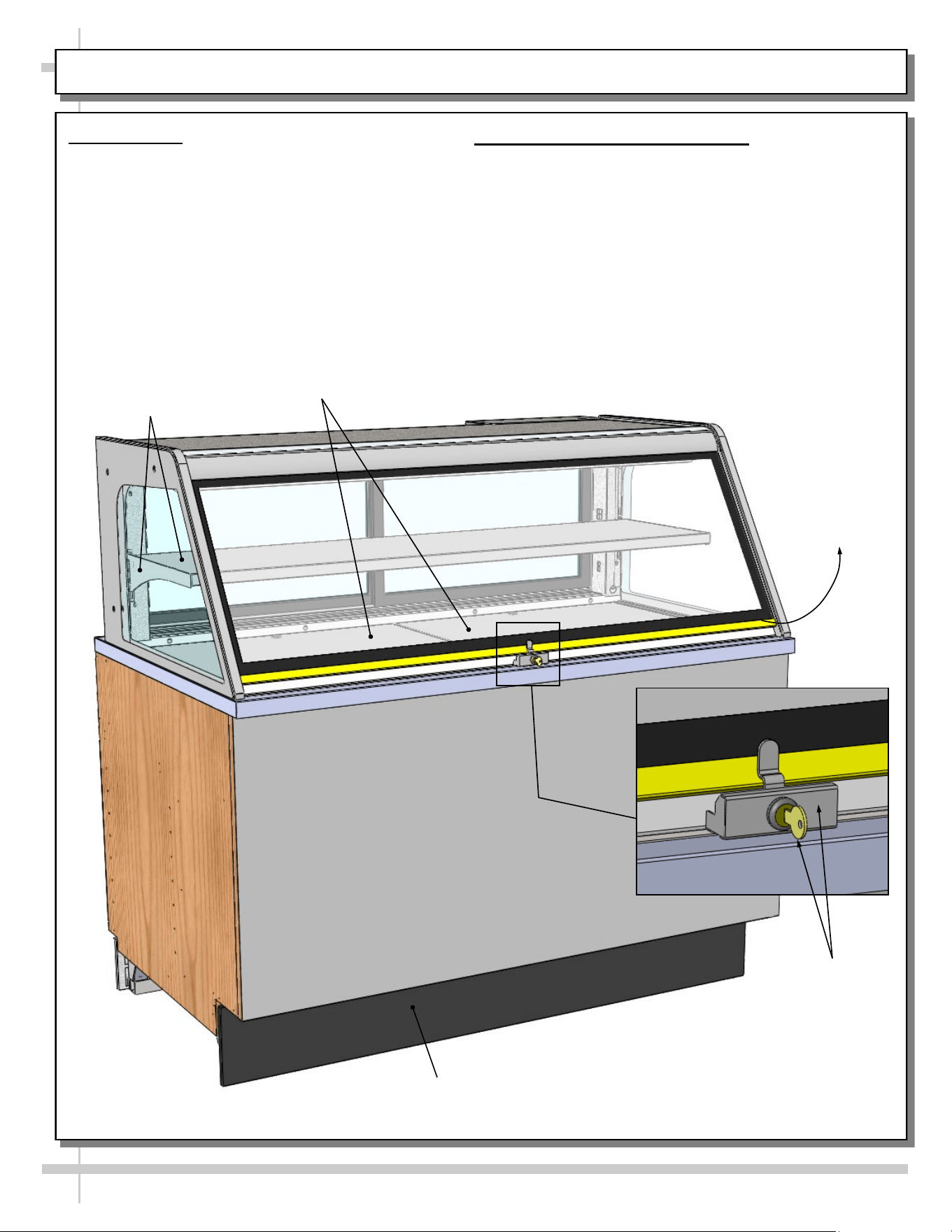
MODEL CDR5745A (SERVICE CASE ONLY) - OVERVIEW OF CASE FRONT
1. Front Glass
• Front glass may be raised for cleaning or
service.
• A lock and key prevent front glass from being
raised. Store key in safe place.
Decking
2. Shelf and Bracket is Adjustable
• As illustrated below, brackets can be adjusted
(up or down).
Shelf &
Bracket
Upper Section
Lock/Key
Front Glass
May Be Raised
Front
Toe-Kick
21
MODEL CDR5745A (SERVICE CASE ONLY) - OVERVIEW OF CASE REAR
1. Scale Stand and Outlet
• Scale stand and outlet provides support and
electrical means for scale.
• Caution! Use only approved plug for outlet.
2. Rear Sliding Doors
• Rear sliding doors are removable for cleaning
and/or serving.
• Use care when removing from case to prevent
glass breakage.
3. Rear Storage Area and Shelves
• Rear storage area and shelves may be used for
storing store supplies.
• See cleaning section in manual.
Rear
Toe-Kick
Rear Storage
Area & Shelves
4. Rear Toe-Kick
• Rear toe-kick may be removed by lifting up and off.
• No screw removal is required.
5. Thermometer Bracket
• Digital thermometer is attached to a suspended
bracket toward rear of case.
• Rear door may be opened (by sliding right-to-left)
to view thermometer’s temperature.
• See illustration below-right.
• Note 1: Thermometers reflect warmest air
temperature in merchandiser. They do not
provide actual food temperature.
• Note 2: Use probe thermometers to determine
actual product temperatures.
Scale Stand &
Outlet
Rear Sliding
Doors
Thermometer Bracket
& Thermometer
22
MODEL CDR5745A (SERVICE CASE ONLY) - OVERVIEW OF LED LIGHTS / AIRFLOW / SHELVING
1. LED Lights
• Model CDR5745A has LED lights only).
• Lights may be removed for replacement.
• See LED LIGHT REMOVAL/REPLACEMENT,
PLUG/CORD POSITIONING, PROPER PLUG
INSERTION section in manual for specifics on
care and maintenance.
2. Front Glass
• Front glass may be raised for cleaning or
servicing.
3. Shelf and Bracket is Adjustable
• As illustrated below, shelf can be adjusted (up or
down).
• Slots in upright allow brackets to be raised or
lowered.
4. Air Discharge / Air Return
• As shown below, air discharge is at case rear.
• Air return is at front of case.
Upper Section
LED Lights
Lower Section
LED Lights
Air Return
Evaporator Coil, TXV, Fans, Etc.
(Under Decking)
Shelf, Bracket &
Slotted Upright
Front Glass
May Be Raised
Air Discharge
23
MODEL CDR5745A (SERVICE CASE ONLY) - OVERVIEW OF EVAPORATOR COIL, FAN, DRAIN, ETC.
1. Tub Layout
• Illustration below reflects partially disassembled
merchandiser.
• Decking has been removed to show various
components.
• Fan, motor, trough, drain, valves, etc., are
shown below.
2. Cleaning Schedule
• See CLEANING SCHEDULE - TO BE
PERFORMED BY STORE PERSONNEL section in
this operating manual for cleaning instructions.
Evaporator
Coil
Drain
Solenoid
Fan, Motor,
Shroud
Refrigeration
Lines
Balancing
Valve
Trough
Sweat
Valve
Tub
Cover,
Evaporator Coil
--- Front of Model CDR5745A ---
24
MODEL CDR5745A (SERVICE CASE ONLY) - OVERVIEW OF UNDERSIDE OF UNIT
Model CDR5745A Underside
• Illustration below reflects view of case
underside.
• Drain/P-Trap must be properly connected to floor
drain at installation.
• J-box must be field-wired.
• Ballast (as shown outlined below) is in main
electrical box.
Drain / P-Trap
Ballast Box
--- Underside of Model CDR5745A ---
Refrigeration
Lines
J-Box
25
MODEL GP441RG.6122 (REF. SELF-SVC GRAB-N-GO FRONT WITH SELF-CONT. REFRIG. UNIT ATOP)
MODEL GP441RG.6122 ONLY
1. Energizing Case
• Case will energize when properly field-wired.
• Upper display unit, has its own on/off switch.
• See wiring diagram that accompanies case.
2. Front Grab-N-Go Section
• Grab-N-Go section is at front of case.
• It consists of decking and shelving.
• See illustration below.
3. Rear Refrigerated Section
• Rear refrigerated section accessible via sliding
doors.
• See illustration below.
4. Upper Display Refrigeration Unit
• Hoshizaki Model HNC-120BA-L-S upper
display refrigerated unit is used for this
merchandiser.
• Unit is self contained and rests on top of case
(as shown in illustration below).
• Unit has its own on/off switch.
• Consult the Hoshizaki operating manual that
accompanies upper display refrigeration unit for
operational specifics.
> See next page for Model GP441RG.6122 upper
display refrigeration unit’s power cord route /
refrigeration line route.
--- Case Front ---
--- Case Rear ---
Note: Self-Contained Upper Display Refrigeration Unit
To Sit Atop Merchandiser. For SCC Model
GP441RG.6122, Hoshizaki Model HNC-120BA-L-S Is
Used. Consult Its Installation and Operating Manual
(or Access Information at www.hoshizaki.com) For
Specifics Regarding Its Design, Electrical Connections,
Drain Connections, Startup, Warnings, Maintenance
and Cleaning of Unit.
Rear Sliding Doors
Hoshizaki Upper
Display Refrigeration
Unit’s Lines &
Connections
Dedicated Outlet
for Upper Display
Refrigeration
Unit
Unit Cooler
Fan Assembly
Sanalite
Wrapping /
Cutting
Board
26
MODEL GP441RG.6122 UPPER DISPLAY REFRIG. UNIT POWER CORD ROUTE / CONDENSATE LINE
MODEL GP441RG.6122 ONLY
1. Power Cord Route
• Power cord is at rear of upper display
refrigeration unit.
• Unit has its own on/off switch.
• Consult the Hoshizaki operating manual that
accompanies upper display refrigeration unit
for operational, cleaning and maintenance
specifics.
2. Condensate Drain Line Route
• Upper display refrigeration unit’s condensate drain
starts at rear of unit.
• It is then routed downward to floor drain.
• See illustration below.
Model GP441RG.6122 Shown
Partially Disassembled For
Illustrative Purposes Only
Upper Display Refrigeration
Unit Power Cord To
Connect To GFCI Outlet
Dedicated Outlet
For Upper Display
Refrigeration Unit
Upper Display
Refrigeration Unit
Condensate Drain
Elbow
Hoshizaki Model HNC-120BA-L-S
Upper Display Refrigeration Unit
Upper Display
Refrigeration Unit
Condensate
Drain Line
Upper Display
Refrigeration Unit
Condensate P-Trap
& Drain
27
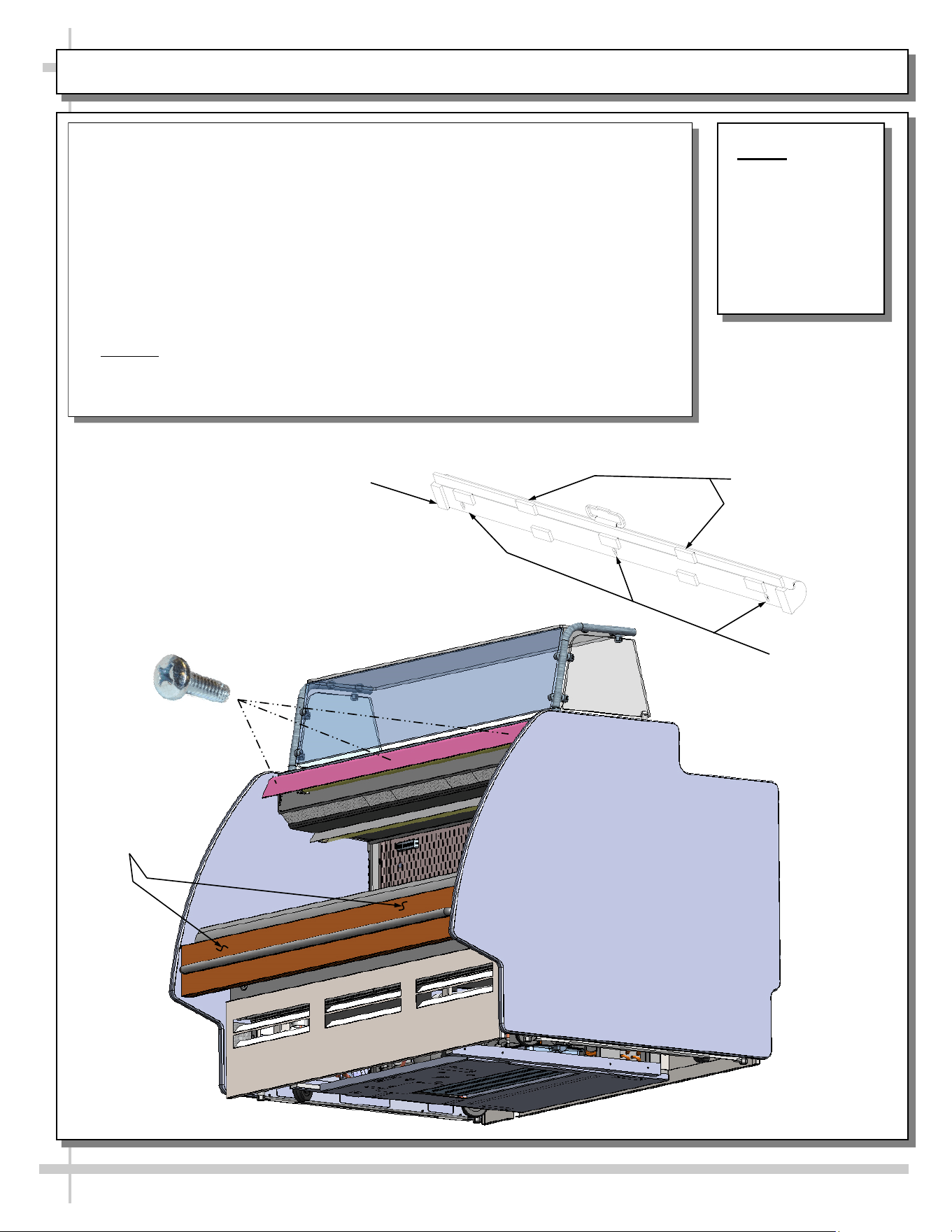
Night Air Curtain
Keyslots
NOTE: BELOW
ILLUSTRATION
MAY NOT
EXACTLY
REFLECT YOUR
CASE’S
FEATURES OR
OPTIONS.
Night Air Curtain Installation & Operating Instructions
1. Use caution when handling Night Air Curtain.
2. Display case may come with Night Curtain already attached. If not, a retrofit kit will
be provided.
3. If using SCC-supplied retrofit kit, place night curtain on top of case as shown. Mark
“keyslot” locations using underside of night curtain as a template. Drill pilot holes in
light shield and screw in #10-32 screws (leaving head exposed to allow “keyslots” to
fit over them). Attach Night Air Curtain to unit by #10-32 screws.
4. After Night Air Curtain is firmly attached to case, grasp handle and pull downward to
desired location (as shown below).
5. To return Night Air Curtain to its retracted position, grasp handle, lift up and away
from its magnetic attachment and carefully wind Night Air Curtain back into roll.
6. Caution! Do not allow spring-loaded Night Air Curtain to freely snap back into roll.
Doing so can eventually destroy Night Air Curtain’s tension and retractability.
7. To entirely detach Night Air Curtain from case, retract curtain (to access keyslots),
remove screws. Lift Night Air Curtain upward and away from case.
Night Air Curtain
Retraction
Magnets
Attachment Points
View of Night Air Curtain
(Underside / Detached)
Night Air Curtain
Retraction Magnets
#10-32 screw (to be
Inserted Into Light Shield
at Locations Matching
Night Air Curtain Keyslots)
MODEL GENERIC - OPTIONAL NIGHT AIR CURTAIN INSTALLATION / OPERATING INSTRUCTIONS
•
•
•

28
CLEANING SCHEDULE / PREVENTIVE MAINTENANCE / TROUBLESHOOTING
CLEANING
SCHEDULE /
PREVENTIVE
MAINTENANCE /
TROUBLESHOOTING
29
CLEANING SCHEDULE - BY STORE PERSONNEL: CRUMB TRAY / GRAB-N-GO AREA
AREA FREQ. INSTRUCTIONS
Air Discharge
Crumb Tray
(On Certain
Models Only)
Daily /
Weekly
Daily
• Air discharge crumb tray (MODEL GP540RRLB.5571B only).
• Slide rear doors open. Lift air discharge crumb trays up and out.
• Empty and return to case.
Weekly
• Perform above steps, but after emptying crumbs, submerse in warm, soapy
water, clean with soft-bristled brush. Dry and return to case.
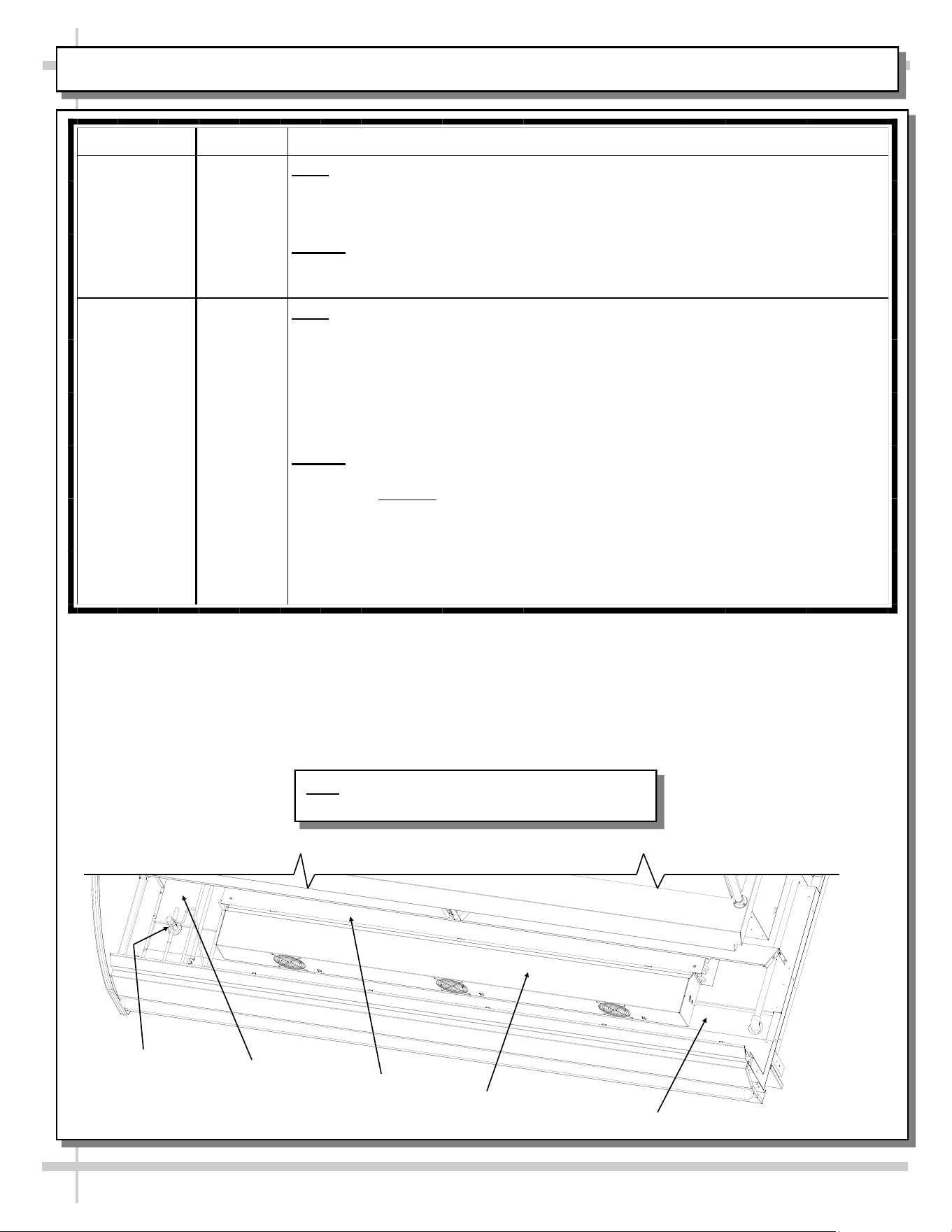
Front Grab-N-
Go Area
Daily /
Weekly
Daily
• Wipe down deck pans (deck pans have been removed for illustrative purposes
below) with warm, soapy water. Rinse with water-filled spray bottle and sponge
or clean cloth. Dry.
• For large spills or hardened residue, remove deck pans and submersed in warm
soapy water, and clean with sponge or cloth.
• Caution! Do not use Brillo® pad or similar abrasive cleaners as they may mar
decking finish. Rinse. Dry. Return decking to case.
Weekly
• Remove deck pans (deck pans have been removed for illustrative purposes
below). Caution! Due to functioning cooling fans, it is advisable to turn off power
to unit at this step.
• After pan covers, pans, dividers and pan supports are removed, clean entire area
(sides, tub, drain, Coil Cover and TXV) with warm water, mild soap solution and
soft cloth. Dry thoroughly.
• Replace all items in reverse order in which they were removed.
Trough
Fan
Shroud
TXV
Tub
Coil
Cover
Note: Illustrations shown may not exactly reflect
every feature or option of your particular case.
30
CLEANING SCHEDULE - BY STORE PERSONNEL, CONT’D: SNEEZE GUARD GLASS, ACRYLIC, ETC.
FREQ. INSTRUCTIONS
Daily Sneeze Guard Glass/Supports/Glass Sliding Doors: After removing pans, clean with a household or
commercial glass cleaner and a soft cloth or paper towel. Wipe off all residue.
Daily Acrylic: Acrylic sneeze guards and bins must be cleaned with a mild soap and water solution and a soft
cloth. Caution! Never use ammonia-based cleaners on acrylic. Incorrect cleaning agents or
abrasive cleaning cloths cause surface to ‘cloud’ over time.
Daily End Panels, Front Panel, Toe-Kick, Sliding Doors (Model GP841R.5184, Etc.), Storage Area,
Condiment Covers, etc.: Wipe with warm water & mild soap solution and non-abrasive cloth.
Daily Stainless Steel Surfaces: See CLEANING SCHEDULE - TO BE COMPLETED BY STORE
PERSONNEL, CONT’D: STAINLESS STEEL section in this manual for cleaning specifics.
Daily Storage Areas, Glove Box Holder, Sanalite Wrapping/Cutting Board: Wipe out with warm water and
mild anti-bacterial soap solution and non-abrasive cloth. See illustration below.
Daily Risers: Wipe down with warm water and mild anti-bacterial soap solution & non-abrasive cloth. For more
extensive cleaning (stubborn stain removal), remove from case, submerse in warm, soapy water and use
non-abrasive cloth. Note: See PREVENTIVE MAINTENANCE (TO BE PERFORMED BY TRAINED
SERVICE PROVIDER) section in manual for sample view of risers.
31
CLEANING SCHEDULE BY STORE PERSONNEL, CONT’D: ENGINEERED/SYNTHETIC QUARTZ
Engineered
Quartz
Overview
Engineered (Synthetic) Quartz Overview:
• Engineered (synthetic) quartz is a ‘man-made’ product. It is sometimes called “engineered stone.” It is made from
crushed quartz particles bonded with polyester, styrene, resin, pigments and tert-butyl peroxybenzoate.
• It is non-porous, mold and mildew-resistant, and impervious to odor-causing bacteria.
• Slabs are specifically sized. Engineered quartz contains a maximum of 94% mineral quartz (though percentages
vary). Engineered quartz is extremely resistant to damaging chemicals.
• There are many engineered (synthetic) quartz brands. These include Caesarstone, Cambria, Compac, Corian, Daltile
ONE, Granite HanStone, Transformations, Kowalski, LG Hausys, LG Viatera, Lunastone, Marble.com, MSI Q, Okite,
Pental, Polarstone, Pompeii, Samsung, Sensa, Silestone, Stone Italiana, Vadara, Vena & Vicostone.
Routine
Care
For Daily, Routine Care and Cleaning:
Engineered (synthetic) quartz require very little maintenance. Simply wipe the surface with neutral pH balanced
household detergent and warm water solution with soft sponge or microfiber cloth to maintain its shine.
• To prevent fading, keep from harsh, direct sunlight for long periods of time.
• General cleaners: use neutral pH balanced household detergent and warm water (4 cups of water/1 teaspoon of
detergent). Or isopropyl alcohol (aka rubbing alcohol). Or use any general, all-purpose cleaner, glass cleaner or Pine
Sol. Or use Clorox Wet Wipes (as they contain no bleach or and are soft). After cleaning, thoroughly rinse with water
and dry with clean cloth to prevent water spots from forming.
• Specifically designed cleaners for manufactured quartz: Black Diamond Stoneworks Granite Counter Cleaner,
Caldrea Countertop Spray, Clark’s Natural Stone Spray Cleaner, Granite Gold, Simple Green, Park & Bailey Granite
& Stone Cleaner, Seventh Generation Granite & Stone Cleaner, Stone Care Quartz Clean & Shine, Stone Pro Quartz
Countertop Cleaner, Weiman Quartz Countertop Cleaner and Polish.
Difficult
Spills
For Difficult Spills, Stains and Spots:
• Thoroughly clean with warm water and neutral pH detergent (mixture detailed above) before pursuing next steps.
• Clean up high staining liquids such as coffee, tea, fruit juice, lemon juice, vinegar, wine and tomato juice right away.
Use warm water and neutral pH detergent to do so. After cleaning, thoroughly rinse with water and dry.
• For residues that harden as they dry (food, gum, nail polish, and paint), place wet cloth or paper towel over residue
for 10 minutes (to soften its properties); then gently scrape off residue by using a plastic putty knife or plastic scraper;
avoid metal blades or scrapers if possible; then clean using warm water and soap. If you must use metal razor blade
or scraper, remove gray marks with soap and water. Thoroughly rinse with water and dry to prevent water spots.
• Difficult spots may need to be treated with solutions/chemicals BEYOND warm water and neutral pH detergents: A.
Water/white vinegar mixture: 2 cups of water with 1 tablespoon of white vinegar in spray bottle; spray surface; allow
solution to sit for 2 minutes; wipe off with soft cloth or sponge. B. Soft Scrub Liquid Gel: Apply gel to cloth or sponge
(not directly to quartz surface); wipe the area in a circular motion; repeat until spot is removed. C. Goo Gone
adhesive remover (for sticky residue). Thoroughly rinse the surface with water and wipe dry to prevent water spots.
• Water stain removal: 1 part vinegar + 3 parts baking soda in warm water. Dip cloth in mixture and thoroughly soak
stain. Leave for 5-10 minutes; then scrub area with soft brush. Rinse with water and dry with clean cloth.
Extreme
Heat
Protection
Extreme Heat Protection:
• Engineered quartz is extremely resistant to heat, and can withstand moderately high temperatures for brief periods of
time without being damaged.
• Engineered quartz CAN BE damaged by sudden and extreme temperature changes; thus, use a trivet or a hot pad to
protect its surface from hot pans, hot dishes or small appliances that may reach high temperatures.
Chemicals
To
Avoid
Chemicals To Avoid:
• Nail polish remover (acetone), oil soaps, and furniture cleaners or paint strippers that contain trichloroethane or
methylene chloride.
• Chemicals with an alkaline level of pH >10 (oven cleaners, chloring bleach, lacquer thinner, ammonia, tub and tile
cleaner, borax, etc.)
• Chlorinated solvents (trichloroethylene or methylene chloride)
• Concentrated acids (hydrocyanic acid, hydrofluoric acid, hydrochloric acid, sulfuric acid, nitric acid or CLR)
Caution must be used for the following products on engineered quartz surfaces:
• Avoid using products containing oils or powders as may leave a residue.
• Avoid abrasive scrubs/cleaners (such as Ajax, Comet, Scotch-Brite or oven cleaner) as it dull or discolor the finish.
Common stains like coffee, food, makeup, permanent markers, etc.:
• Apply the appropriate cleaner with a paper towel and wipe. If necessary, soak with paper towels from 3-10 minutes.
• Scrub the area with a non-abrasive cloth or sponge. Rinse and dry thoroughly.
Preventing
Scratches
Scratch Deterrence: Engineered quartz surfaces are scratch RESISTANT. However, they CAN be scratched or marred
by certain utensils or cleaning materials.
• Use a cutting board to avoid damaging the quartz surface and knives.
• Never use abrasive scouring pads, steel wool soap pads, Brillo® pads or “Magic Erasers.

32
CLEANING SCHEDULE - BY STORE PERSONNEL, CONT’D: STAINLESS STEEL
General Stainless Steel Surface Cleaning (To Be Performed As Often As Needed):
• Certain grades of stainless steel, and some are more prone to corrosion than others.
• Stainless steel can become exposed to a wide variety of contaminants, which if left untreated can cause
stains and rust.
• Stainless steel requires a specific cleaning procedure to maintain its sheen and remain rust-free.
• Wash with a solution of liquid dishwashing detergent and hot water.
• Rinse with pure hot water from spray bottle. Wipe with clean sponge. This will remove soap residue
that can lodge in stainless steel’s microscopic grooves, causing rust.
• Dry with clean, soft cloth or paper towel.
• Caution! To prevent rust, you MUST rinse with pure hot water from a spray bottle while wiping with
clean sponge after EACH cleaning.
• Caution! Never clean with scouring powder or steel wool as they can mar, scratch and/or erode the
surface of stainless steel. When the surface properties of stainless steel have been compromised, rust
can form.
Brightening:
• Method 1: Brighten by polishing with a soft cloth or sponge with a solution of one part vinegar to 2 parts
water in a spray bottle.
• Method 2: Sprinkle baking soda on sponge and rub gently with soft cloth or sponge.
• Caution! To prevent rust, you MUST rinse with pure hot water from a spray bottle while wiping with
clean sponge after EACH cleaning.
• Dry with clean, soft cloth or paper towel.
Removing Streaks or Stains:
• Method 1: Place two teaspoons of rubbing alcohol on a microfiber cloth or pad. Rub the cloth along the
grain of the appliance until the entire area has been wiped. The rubbing alcohol will air dry itself.
• Method 2: Dip soft cloth or sponge in club soda and rub gently over area of concern.
• Caution! To prevent rust, you MUST rinse with pure hot water from a spray bottle while wiping with
clean sponge after EACH cleaning.
• Dry with clean, soft cloth or paper towel.
Polishing:
• Place a dab of olive oil onto clean soft cloth. Spread over area until a light sheen is observed. Use
pressure to “work the oil” into the small grooves in the surface. Apply firm, steady pressure using small
circular motions.
> Dry buff: Remove excess oil with clean cloth or paper towel using small circular motions.
> Wet buff: Use an ounce or white vinegar with clean cloth or paper towel using small circular motions.
> Continue wiping until oily finish has been removed.
• Caution! To prevent rust, you MUST rinse with pure hot water from a spray bottle while wiping with
clean sponge after EACH cleaning.
• Dry with clean, soft cloth or paper towel.
Removing Rust:
• If rust has begun to form, there are a variety of products that can treat it.
• Among these are CLR® (calcium, lime and rust remover) and Chemetall Oakite 33 (rust, oxides and
scale remover).
• Caution! To prevent food contamination, personal injury or further corrosion, carefully
observe and follow the rust removing product’s precautions and instructions.
33
PREVENTIVE MAINTENANCE (TO BE PERFORMED BY TRAINED SERVICE PROVIDERS)
PREVENTIVE
MAINTENANCE
FREQ. INSTRUCTIONS
Case Interior Quarterly Tub Area (Evaporator Coil, Drain, Fans, Brackets):
Caution! Disconnect power from the case before cleaning tub, coil,
fan, motor and drain area!
• Use vacuum to clean entire area.
• After vacuuming, clean area with warm water, clean cloth, and mild
soap solution.
• Remove any debris that may clog drain.
• Wipe down fan blades, motors and brackets with moist cloth.
Quarterly Honeycomb: Check honeycomb air diffuser to determine if it is dirty.
If it is dirty, remove from case. See MAINTENANCE FUNDAMENTALS -
HONEYCOMB AIR DIFFUSERS (SERVICE TECHNICIANS ONLY)
section of this manual (next page) for cleaning specifics.
WARNING! TURN OFF CASE BEFORE PERFORMING PREVENTIVE MAINTENANCE!
Honeycomb (Typical)
Model GP340DRLB.5580
Risers (Typical)
34
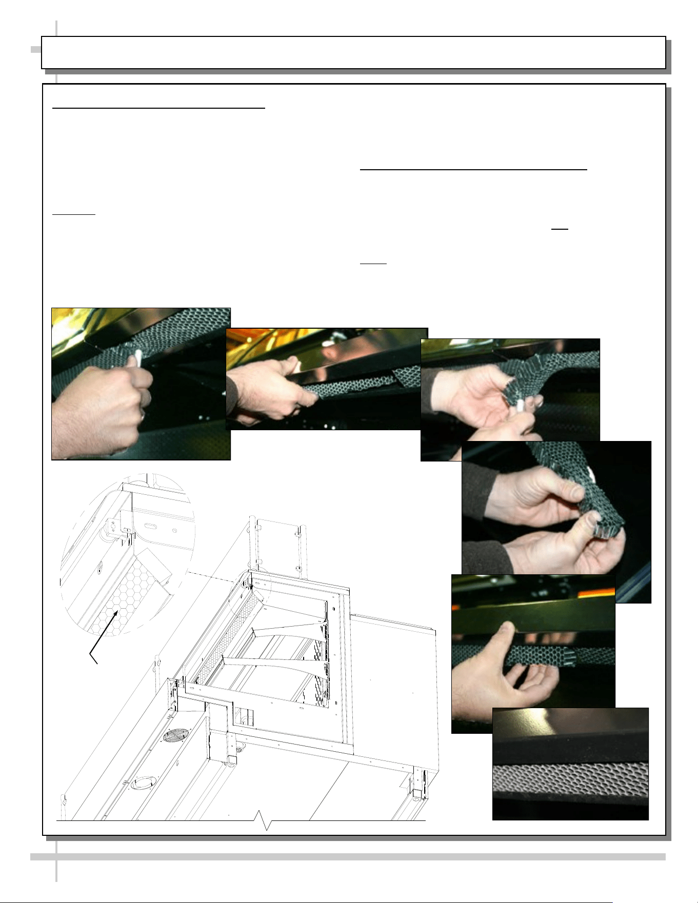
PREVENTIVE MAINTENANCE (TO BE PERFORMED BY TRAINED SERVICE PROVIDER), CONT’D.
1. Honeycomb Air Diffuser Removal
See PREVENTIVE MAINTENANCE (TO BE
PERFORMED BY TRAINED SERVICE PROVIDER)
section in this manual for cleaning frequency.
A. Wedge a non-metallic device of suitable strength
(such as a ballpoint pen) between the honeycomb
and the end panel.
Caution! Use care not to dislodge the heating wire
(that prevents condensation on the lamp assembly).
B. Apply pressure to collapse the honeycomb to
allow it to be pulled out of honeycomb retainer.
C. Carefully pry downward and away from the
honeycomb retainer.
A
B
C
D
E
F
Clean honeycomb with warm water and soap
solution. Submerse if necessary. Use brush to
dislodge stubborn or sticky residue. Dry by using
vacuum’s blow mode (vs. suction mode).
2. Honeycomb Air Diffuser Installation
D. Squeeze honeycomb to allow it to fit into the
honeycomb retainer.
E. Carefully slide honeycomb into place.
F. Adjust honeycomb so that it fits flat against
retainer. It must not be wavy or out of position.
Note: For honeycomb air diffusers in other
locations, these same general instructions apply.
Honeycomb
Model Shown With
End Panel Removed
for Illustrative
Purposes. Your
Model May Differ.
35
TROUBLESHOOTING (TO BE PERFORMED BY STORE PERSONNEL)
CONDITION TROUBLESHOOTING
Case Is Not Level See INSTALLATION section in this manual for additional information.
Case Not Lining Up See INSTALLATION section in this manual for instructions on properly
aligning case (alongside other cases) and adjusting levelers (or rails).
Water Is On The Floor Call service provider.
Fan Emits Excessive Noise Call service provider.
Case Lights Are Not
Working
Check that light switch is in the on position.
Turn light switch off and check bulb for proper connection.
• Check that the light cord is plugged in properly.
• Note: LED light and plug must be connected in a specific manner or
they will not work.
• Make certain flat edge of plug connects to flat edge of LED light.
• See LED LIGHT REMOVAL/REPLACEMENT, PLUG/CORD
POSITIONING, PROPER PLUG INSERTION section in this manual
for illustrations.
Fluorescent lights: Check bulbs for proper installation and connection.
Also, check that bulb connections are free from dust and dirt.
Fluorescent lights: Check for burned out bulbs.
If case lights still do not come on, call service provider.
Case is Not Holding Proper
Temperature
If a large amount of warm product was added to the case, it will take time
for the temperature to adjust. Product must be pre-chilled before placing
in case.
Check that the case is not in the sun or near a heat or air-conditioning
vent.
If case is located near front doors, temperature fluctuation can hinder
unit’s ability to maintain temperature.
Check air return grilles (area at front of decking) for obstructions.
DO NOT set product on air grilles as this will prevent proper airflow!
If case still is not holding proper temperature, call service provider.
36
TROUBLESHOOTING (TO BE PERFORMED BY TRAINED SERVICE PROVIDERS)
CONDITION TROUBLESHOOTING
Water Is On The Floor Check that drain trap is free of debris.
Check that the drain hose is correctly positioned over floor drain.
Check store conditions.
• To prevent condensation in NSF/ANSI Type I environments, maximum
conditions are to be 55% relative humidity / 75° Fahrenheit.
• For NSF/ANSI Type II environments, maximum conditions are to be
55% relative humidity / 80° Fahrenheit.
• If you are unsure if your unit is classified as NSF/ANSI Type I or Type
II, see tag next to serial label on your case.
Fan Emits Excessive Noise Check that the case is aligned, level and plumb.
Check evaporator fans for cleanliness.
Unplug/power off fan motors. Check to determine whether faulty.
Check that fan motors are securely mounted in brackets.
Check that the fan shroud is properly secured.
Fans Are Not Working Check that fans are plugged in at the fan shroud.
Check for foreign material obstructing fan performance.
Check that fan blades freely rotate within fan shrouds
Check that power is going to fans (certified electricians only).
Check that fan wiring is connected on terminal blocks (certified
electricians only).
System Is Not Operating Check that the utility power is on.
Check the circuit breaker box for tripped circuits.

37
TECHNICAL INFORMATION (THERMOSTAT / SERIAL LABEL / WARRANTY / TECH. SVC. INFO., ETC.)
TECHNICAL
INFORMATION
(THERMOSTAT /
SERIAL LABEL /
WARRANTY /
TECHNICAL SERVICE
INFO., ETC.)
38
SERIAL LABEL LOCATION & INFO LISTED / TECH INFO & SERVICE / REFRIGERATED CASES ONLY
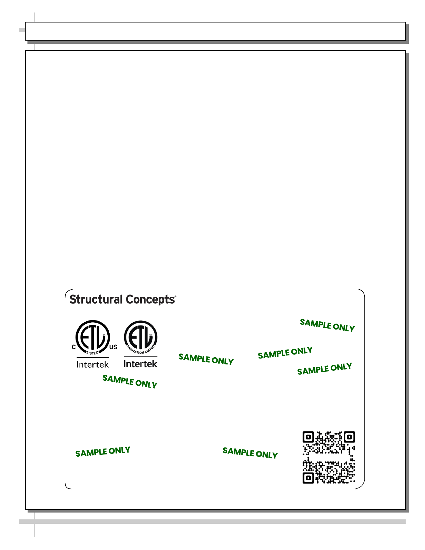
--- Sample Serial Label For Refrigerated Cases ---
MODEL NRS3648RXV-SAMPLE
SERIAL NO. 12345X30DZ098765
888 E. Porter Rd - Muskegon, MI 49441
3048256
Conforms to UL Std. 471
Conforms to NSF/ANSI Stds. 2 & 7
CERTIFIED TO CAN/CSA
STD C22.2 NO 120
ELECTRICAL RATING
REFRIGERANT
DESIGN PRESSURE
MINIMUM CIRCUIT AMPACITY
MAXIMUM OVERCURRENT
120/1/60 16 A
R513A AMOUNT 50 OZ
HIGH 186 LOW 88
20A
20A
Super Heat Temp 6-8 °F FOR PARTS AND SERVICE
Defrost 6 defrosts per day, 45 °F CALL 1-800-433-9490
Serial Label Location & Information Listed /
Technical Information & Service
• Serial labels are affixed at a wide range of places
(on the header, near thermostat, at case rear,
behind panels/toe-kicks, on electrical boxes, etc.).
• Serial labels contain electrical, temperature and
refrigeration information, as well as regulatory
standards to which the case conforms.
• Sample serial label shown below.
• For additional technical information and service, see
the TECHNICAL SERVICE page in this manual for
instructions on contacting Structural Concepts’
Technical Service Department.
Fusion
Sample QR Code
SCAN FOR PRODUCT LITERATURE
SAMPLE ONLY
SAMPLE ONLY
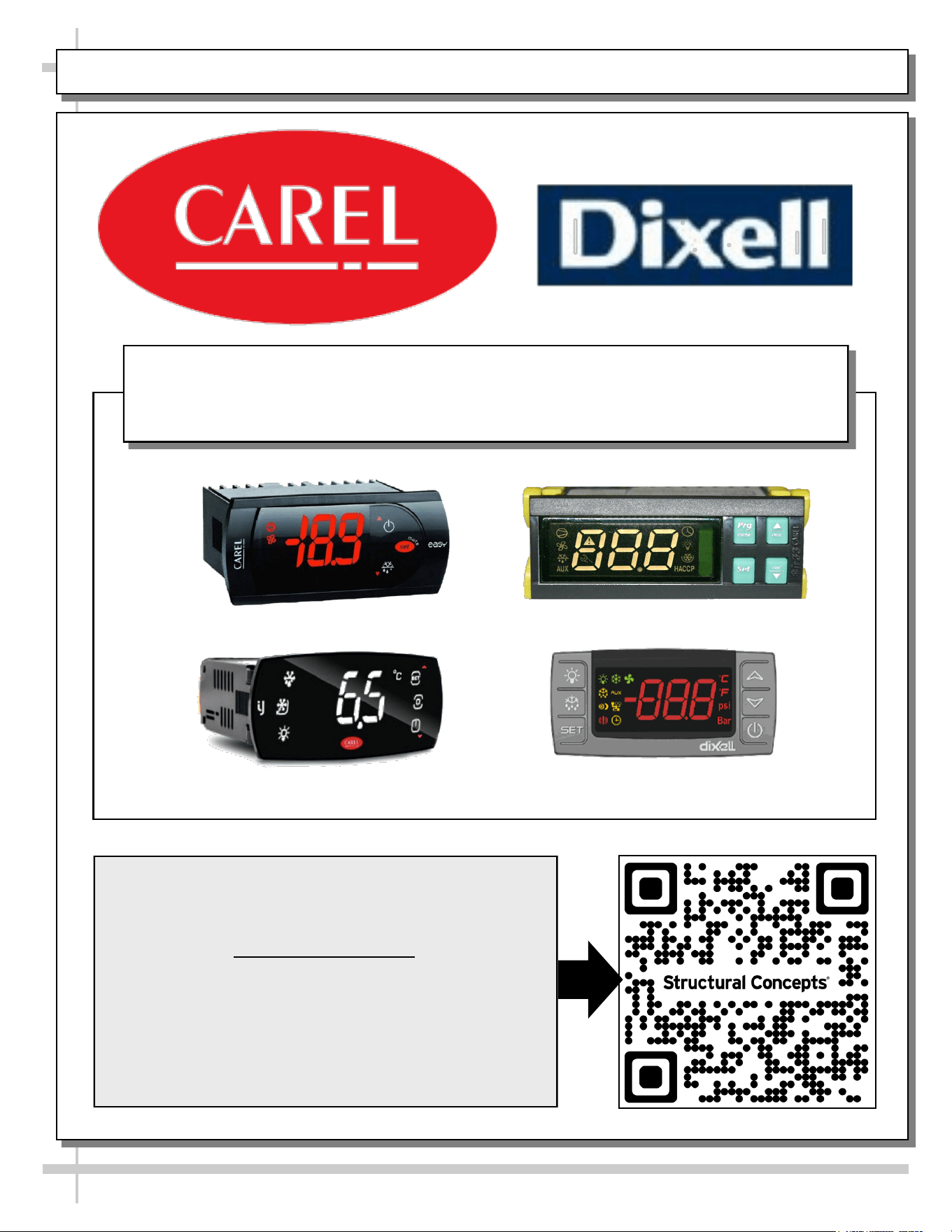
PROGRAMMABLE CONTROLLER (SELECT, CLICK ON OR SCAN QR CODE FOR INFORMATION)
39
Carel® iJF Platform
Carel® PJEZ Platform
Carel® ir33 Platform
Dixell® XM670K-XM679K Platform
To Access Information About The Programmable
Controller That Is Used On Your Case,
Follow These Instructions:
> If Viewing This Document on Smart Phone, Tablet
or Computer, Select/Click On The QR Code at Right.
> If Viewing This Document In Print (Hard Copy),
Scan The QR Code at Right With Your Smart Phone
or Tablet.
Determine Which Programmable Controller Is On Your Case (Controllers
That Are Commonly Used By Structural Concepts Are Shown Below).
Your Particular Programmable Controller May Differ.
STRUCTURAL CONCEPTS TECHNICAL SERVICE CONTACT INFORMATION & LIMITED WARRANTY
40
TECH SERVICE/WARRANTY CONTACT INFO:
1 (800) 433-9490 / EXTENSION 1
DAYS/HOURS AVAILABLE:
MONDAY - FRIDAY (CLOSED HOLIDAYS)
8:00 P.M. to 8:00 P.M. EST
YOU MUST HAVE THE FOLLOWING INFO AVAILABLE
BEFORE CONTACTING STRUCTURAL CONCEPTS:
SERIAL NO. / MODEL NO. / STORE NO. / STORE
ADDRESS / DETAILS (PHOTOS, LEAK LOCATIONS,
DAMAGE, STORE’S AMBIENT CONDITIONS, ETC.)
To Access The Limited Warranty To Your
Case, Follow These Instructions:
> If Viewing This Document on Smart Phone,
Tablet or Computer, Select/Click On The QR
Code at Right.
> If Viewing This Document In Print (Hard
Copy), Scan The QR Code at Right With Your
Smart Phone or Tablet.