
INSTALLATION, OPERATION, AND
MAINTENANCE MANUAL FOR ELECTRIC TANKLESS WATER HEATERS
SPECADVANTAGE | SAFE ADVANTAGE

i
IMPORTANT SAFETY INFORMATION
READ ALL INSTRUCTIONS BEFORE USING
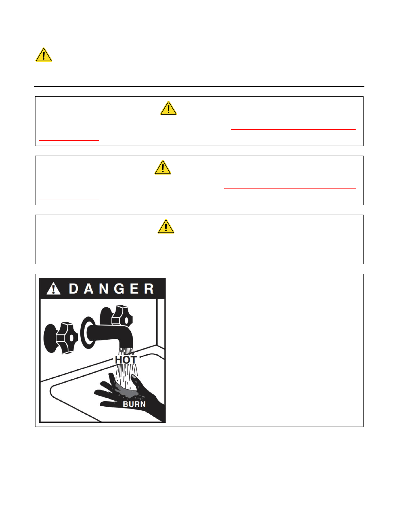
DANGER
Indicates an imminently hazardous situation which, if not avoided, will result in death
or serious injury.
WARNING
Indicates a potentially hazardous situation which, if not avoided, could result in death
or serious injury.
CAUTION
Indicates a potentially hazardous situation which, if not avoided, may result in minor
or moderate injury.
Hot water can be dangerous. There is a high scald
potential if the thermostat is set too high.
Water temperatures over 125 °F (51 °C) can cause
severe burns or scalding resulting in death.
Hot water can cause first degree burns with
exposure for as little as:
3 seconds at 140 °F (60 °C)
20 seconds at 130 °F (54 °C)
8 minutes at 120 °F (48 °C)

ii
IMPORTANT SAFETY INFORMATION
READ ALL INSTRUCTIONS BEFORE USING
1. You must read and follow all
instructions. Serious bodily injury or
death could occur if you ignore this
warning.
2. All circuit breakers and/or disconnect
switches servicing the heater must be
turned off when installing, uninstalling,
or repairing this water heater.
3. The unit must be installed by a
licensed electrician and plumber.
4. The unit must be wired in accordance
with the current version of the
National Electrical Code (US) or
Canadian Electric Code (Canada).
5. This installation must comply with all
national, state, and local plumbing and
electrical codes.
6. When the heater is not within sight of
the electrical circuit breakers, an
additional local means of
disconnection of all ungrounded
conductors must be provided that is
within sight of the appliance or a
circuit breaker lockout must be used.
(Ref. NEC 422.31)
7. Per UL 499, this water heater is not
required to be installed with a
Temperature and Pressure relief valve
(T&P). However, local codes may vary.
In case a T&P relief valve is required, it
must be installed on the outlet hot
water line heater between the heater
and the isolation valve.
8. If the Eemax Tank less Water Heater is
installed in a location where water
damage could occur in the event of a
leak, it is recommended that a drip
pan be installed and connected to a
suitable drain. Alternatively, an active
water leak detector and shut off valve
can be installed to turn off your water
supply in the event a leak is detected.
9. If water supply has a high mineral
content, a water softening system is
recommended. Damage to the water
heater resulting from scale or hard
minerals will not be covered under
warranty.

iii
IMPORTANT SAFETY INFORMATION
READ ALL INSTRUCTIONS BEFORE USING
10. When the heater is installed in a well
water system or if the plumbing
system is prone to introducing air into
the heater, it is highly recommended
that an air separator be installed in the
cold water feed to the heater to avoid
possible failure of the heating element
and/or heating chamber.
11. In accordance with NEC guideline, this
water heater is designed for a
continuous duty cycle of 3 hours at
100% power output. Exceeding this
rating could damage the heater and
void the warranty
12. Provide your heater with potable,
uninterrupted supply of water at a
constant minimum pressure of 35PSI
(based on model) and maximum
pressure of 150 PSI.
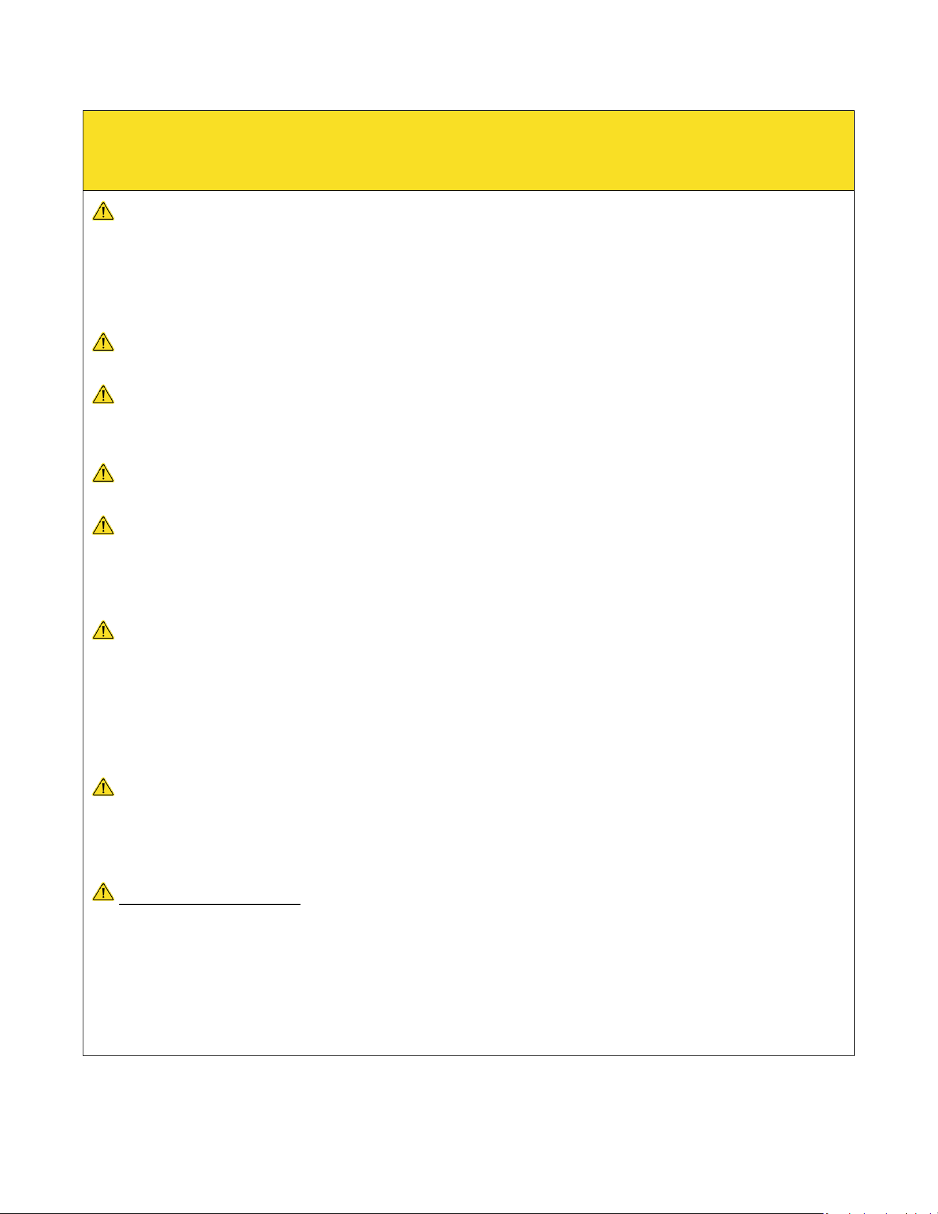
13. Use of Water Hammer Arrestors in
applications with excess pipe lengths
or fast acting valves strongly
recommended, neglecting to do so will
damage the heater and void the
warranty
14. This heater must be in a location
where it is not subject to freezing
temperatures unless supplied with
factory installed freeze protection
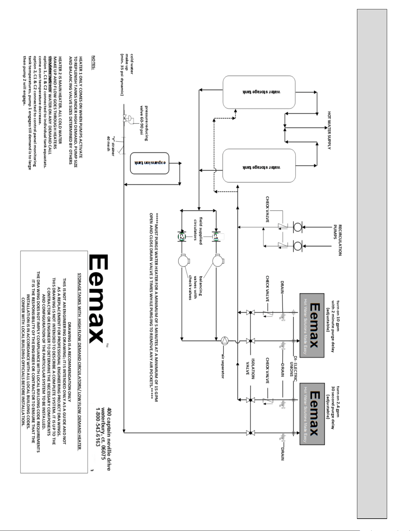
15. Properly purge air out of system
before power is applied.
Recommended to purge water
through system for minimum 2
minutes at a minimum 15 gpm, closing
and opening drain valve 3 times to
move any lodged air before power is
applied.
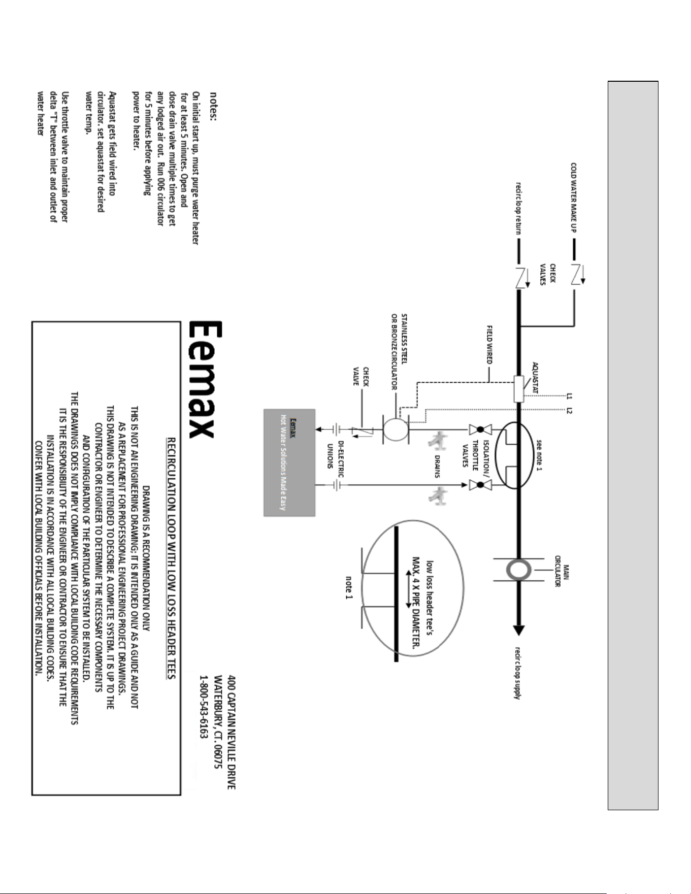
16. Sanitation models used in a circulator
system, a 30 second factory set delay
program will be installed to establish
flow before power is applied. Contact
Eemax for information 1-800-543-6163
17. Applications with the use of a
recirculation circulator must be
installed according schematics.
18. The use of Ethylene glycol antifreeze
is strictly prohibited. Propylene Glycol
is the only recommended antifreeze

iv

v
TABLE OF CONTENTS
PERFORMANCE FEATURES................................................................................................................. 1
OPERATION PRINCIPLE ...................................................................................................................... 3
MOUNTING THE HEATER TO THE WALL ............................................................................................. 4
ELECTRICAL HOOKUP ........................................................................................................................ 5
PLUMBING HOOKUP ......................................................................................................................... 7
COMMISSIONING THE WATER HEATER ............................................................................................ 10
MONITORING & PREVENTIVE MAINTENANCE .................................................................................. 14
CONTROL FEATURES ....................................................................................................................... 15
TROUBLESHOOTING PROCEDURES .................................................................................................. 18
TECHNICAL SUPPORT ...................................................................................................................... 20
APPLICATIONS SCHEMATICS ............................................................................................................ 24
WIRING SCHEMATICS ...................................................................................................................... 61

1
PERFORMANCE FEATURES
Heating Technology
Field Replaceable, non-ferrous, lead-free cartridge-style direct heating element
Safety and Reliability
Thermo-Optical sensor for protection against entrained air or improper commissioning
Materials and Construction
NSF-61 listed materials of construction
Control and Consumption
Active energy management to ensure optimal application of energy based on real-time system demands
Multistage element turn-on
Visual user interface for field programming
Turn-on Flow Rate
Integrated high-capacity flow meter
Field adjustable maximum activation flow rate (minimum activation flow rate factory set and is not field
adjustable.)
Pressure Rating
Operating pressure range not to exceed 60 – 90 PSI. Maximum pressure rating 150 psi
Available Enclosures
N4 – NEMA 4 (Standard)
N4X – NEMA 4X 304SS
N4X6 – NEMA 4X 316SS
Class l Div II enclosures
Optional Features
Indoor disconnect switch (fused or non-fused)
Stand Kits (for freestanding applications)
Beacon
Siren
Alarm contacts
GFCI
FREEZE PROTECTION
Additional Options available per customer request
2

3
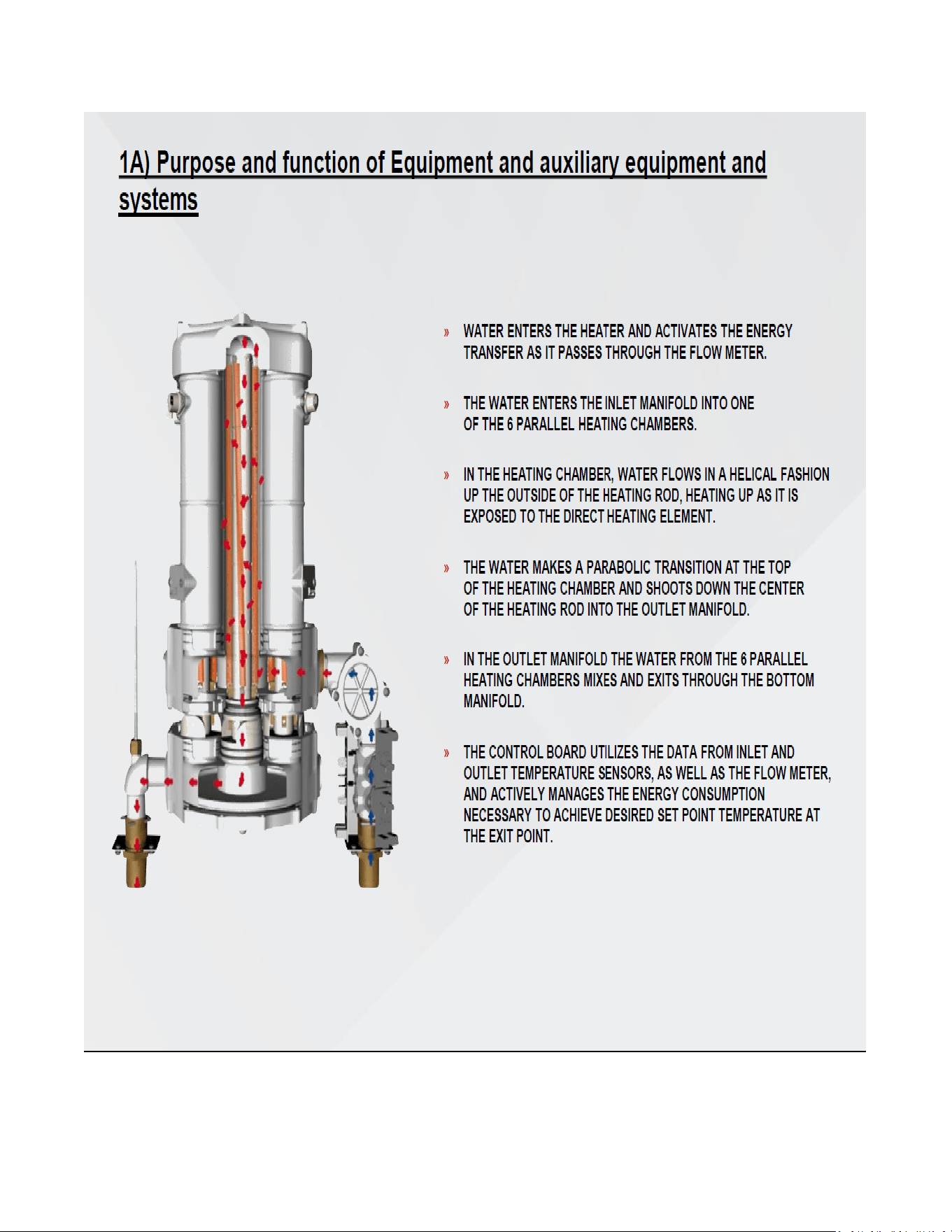
OPERATION PRINCIPLE
How the Eemax Tankless Water Heater Works
Operating the new Eemax tankless water heater is similar to using any traditional water heater system. However, it is
very important that all of the set-up procedures and operating instructions are carefully read to ensure maximum
performance and energy savings from the water heater.
The Eemax tankless water heater does not store hot water like a conventional tank-type water heater. It contains high
powered bare wire technology heating elements that are capable of heating water instantly on-demand. Whenever
there is a hot water demand, the patented flow meter within the heater recognizes the demand and initiates the
heating process. This meter measures the water flow rate while two thermistor sensors measure the incoming and
outgoing water temperature. This information is transmitted continually to the microprocessor controller which
determines the precise amount of power to send to the heating elements to heat the water to the desired temperature.
The Eemax tankless water heater only uses as much power as is needed to meet the demand by fully modulating the
heating elements from 0 to 100%.
It is important to keep in mind that all tankless water heaters are subject to a maximum flow rate. If this flow rate is
exceeded, the heater will not be capable of fully heating water. The amount of water that can be heated by the tankless
water heater at any given time will depend on the model selected and the incoming water temperature. See diagram
on below to determine the maximum flow rates. Since a tankless water heater eliminates the ongoing thermal losses
caused by storing hot water in a tank, there will be a significant energy savings compared to a conventional tank type
water heater.
Temperature Rise at Specified Flow Rate (°F)
MODEL
TURN-ON
GPM
3.0
GPM
4.0
GPM
6.0
GPM
8.0
GPM
12.0
GPM
20.0
GPM
25.0
GPM
30.0
GPM
AP032208
1.0
73
55
36
27
18
10
8
7
AP036208
1.0
82
61
41
29
20
12
9
8
AP041208
1.0
93
70
47
35
23
13
11
9
AP054208
1.5
123
92
61
46
31
18
14
12
AP064208
2.5
146
109
73
55
36
22
17
15
AP036480
1.0
82
61
41
31
20
12
9
8
AP039480
1.0
89
67
44
33
22
13
11
7
AP048480
1.0
109
82
55
41
27
16
13
11
AP054480
1.5
123
92
61
46
31
18
14
12
AP063480
2.5
143
108
72
53
36
22
17
14
AP072480
2.5
147
123
82
61
41
25
20
16
AP096480
2.5
-
-
109
82
54
33
26
22
AP108480
2.5
-
-
99
92
61
37
30
25
AP126480
2.5
-
-
143
107
72
43
34
29
AP144480
2.5
-
-
-
122
82
49
40
34
AP130600
2.5
-
-
-
111
73
44
35
30
AP150600
2.5
-
-
-
128
85
52
40
35
4
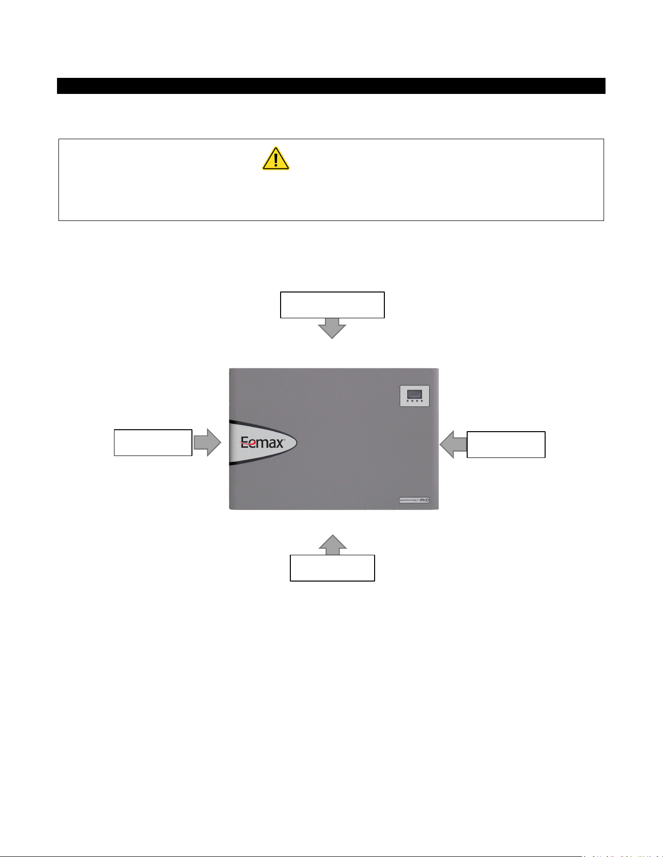
MOUNTING THE HEATER TO THE WALL
Please follow the mounting instructions as appropriate to your installation. Eemax recommends the heater be installed
close to the point of use.
CAUTION
This heater must be installed in a location where it is not subject to freezing
temperatures, unless supplied with factory installed freeze protection
Make sure the brass fittings are at the bottom of the heater. No other heater orientation is permitted.
The AP series is approved for zero clearance to combustibles.
Above clearances recommended for service and installation.
10” Top Clearance
8” Clearance
8” Clearance
18” Clearance
5
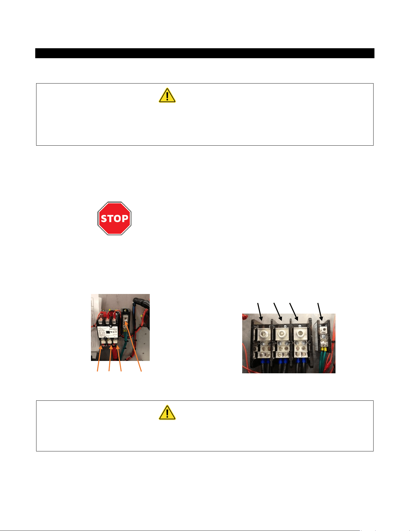
ELECTRICAL HOOKUP
Eemax recommends your heater be installed or serviced by a licensed plumber and electrician.
WARNING
Before beginning any work on this installation, BE SURE THAT THE ELECTRICAL
BREAKER IS “OFF” AND THAT ALL MOUNTING AND PLUMBING WORK HAS BEEN
COMPLETED PER THESE INSTRUCTIONS.
This heater must have its own independent circuit using insulated, UL listed wire conductors of the appropriate size
suitable for up to 90° C and protected by the correctly rated circuit breaker.
See chart on next page.
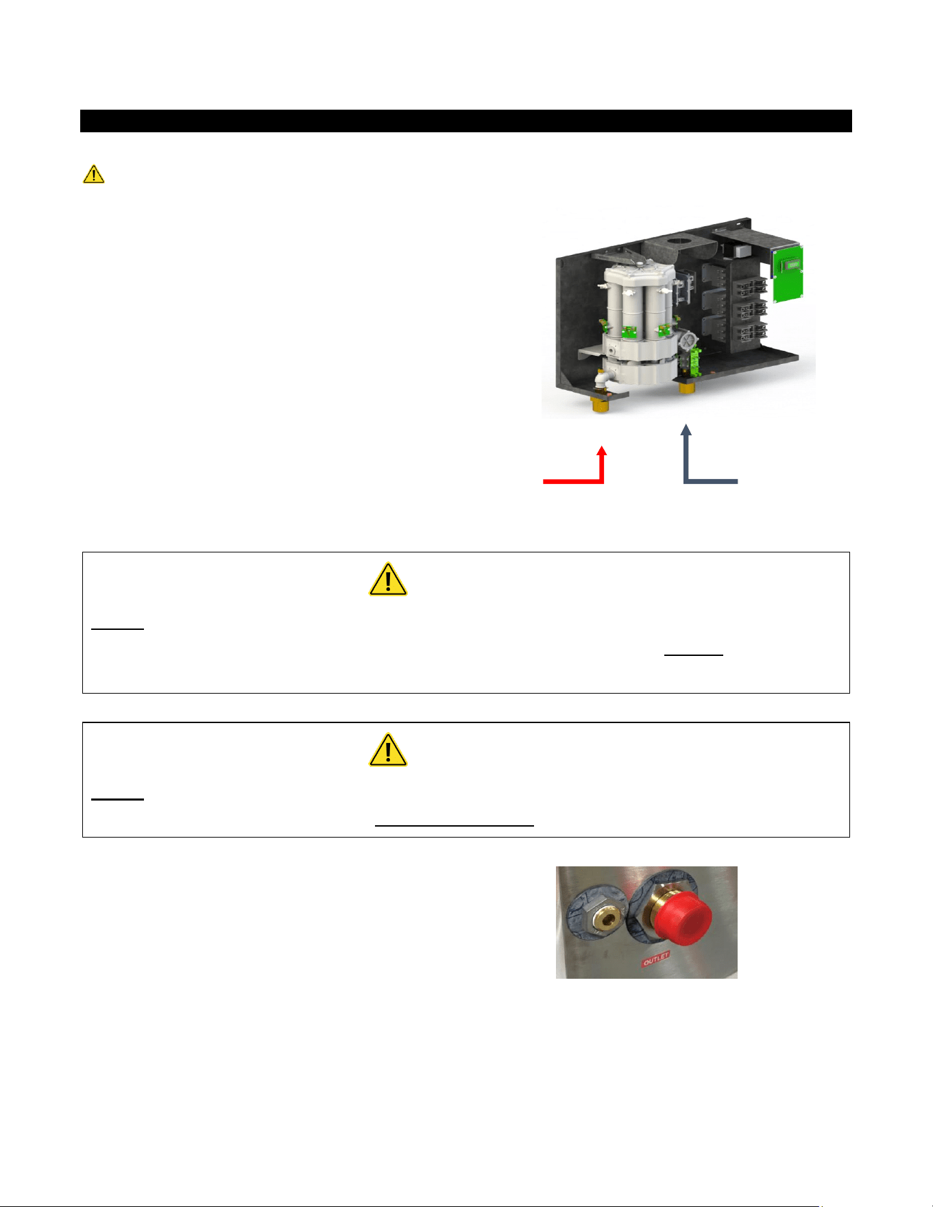
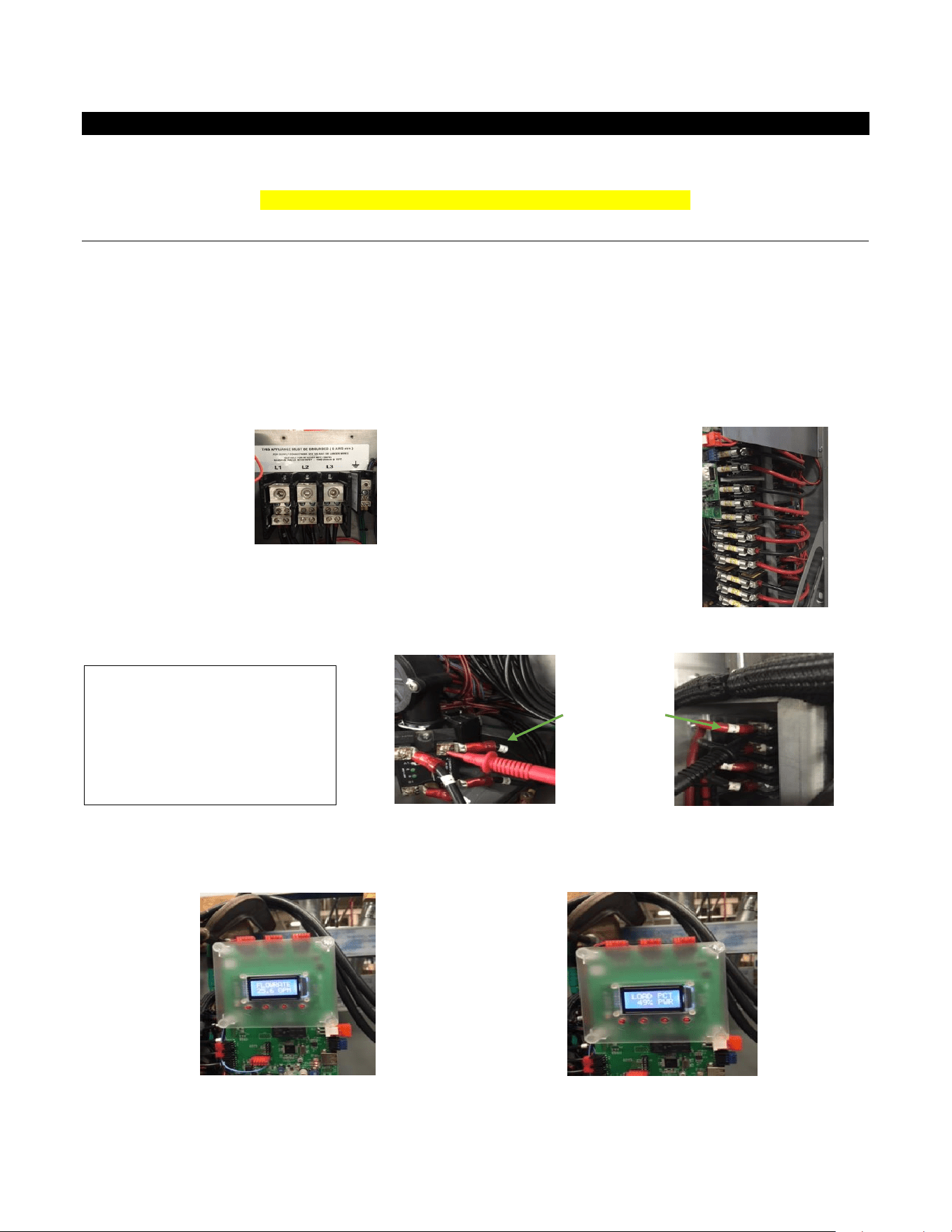
Before starting any electrical work VERIFY there is
no power at the heater before proceeding
The power conductors are to be secured to the L1, L2 and L3 connectors on the terminal block (Fig. 1) or
contactor (Fig. 2). The ground is to be secured to the GND connector to the right of the terminal block.
Fig. 1
L1 L2 L3 GND
Fig. 2
L1 L2 L3 GND
WARNING
FAILURE TO GROUND THE SYSTEM MAY RESULT IN SERIOUS INJURY,
DEATH AND/OR PROPERTY DAMAGE.

6
Electrical Specifications
MODEL
VOLTS
3-PHASE DELTA
KW
AMPS
PER PHASE
RECOMMENDED
WIRE SIZE (CU) 90° C
AP032208
208
32
89
1 AWG
AP036208
208
36
100
1 AWG
AP041208
208
41
114
1 AWG
AP054208
208
54
150
2/0
AP064208
208
64
178
3/0
AP036480
480
36
44
8 AWG
AP039480
480
39
47
8 AWG
AP048480
480
48
58
6 AWG
AP054480
480
54
65
4 AWG
AP063480
480
63
76
3 AWG
AP072480
480
72
86
3 AWG
AP096480
480
96
116
1 AWG
AP108480
480
108
130
1/0
AP126480
480
126
152
2/0
AP144480
480
144
173
3/0
AP048600
600
48
47
8 AWG
AP051600
600
51
50
6 AWG
AP061600
600
61
59
6 AWG
AP071600
600
71
69
4 AWG
AP102600
600
102
99
1 AWG
AP130600
600
130
130
1 AWG
AP150600
600
150
145
1/0
A green terminal (or a wire connector marked “G”, “GR, “Ground”, or “GROUNDING”) is provided within
the control box. To reduce the risk of electric shock, connect this terminal or connector to the grounding
terminal of the electric service or supply panel with a continuous copper wire in accordance with your
local electrical code.
7
PLUMBING HOOKUP
MUST FLUSH LINE A MINIMUM 5 MINUTES, AT A MINIMUM 15 GPM ON INITIAL START UP
The heater is equipped with NPT brass fittings.
Make sure ONLY NPT fittings are used for connection to this heater.
Connect the cold water line with the inlet connection
(RIGHT fitting)
Connect the outlet pipe with the outlet fitting
(LEFT fitting)
Do not reverse connections.
CAUTION
Never use pipe dope when making plumbing connections to this heater. Follow
standard industry practice with careful application of Teflon tape. Do not allow Teflon
tape to get into the heater.
CAUTION
Never solder any pipe connections while attached to this heater – damage to the
heater will result. Doing this will void the warranty.
PRV VENT LOCATION. The PRV Vent is not a code
compliant pressure relief valve. Check local codes to
see if a code compliant T&P Relief Valve is required
in your installation.
HOT
WATER
OUT
COLD
WATER
IN
8
WARNING
MUST FLUSH OUT WATER HEATER FOR MINIMUM 5 MINUTES AT A MINIMUM 15
GPM ON INITIAL START UP OR AFTER ANY SERVICE WORK HAS BEEN PERFORMED.
CLOSE AND OPEN DRAIN VALVE 3 TIMES TO REMOVE ANY LODGED AIR BUBBLES.
FAILURE TO DO SO MAY DAMAGE THE HEATER.
MINIMUM INLET WATER PRESSURE 35 PSI DYNAMIC.
MAXIMUM WATER PRESSURE NOT TO EXCEED 150 PSI. RECOMMENDED
OPERATING PRESSURE 60 – 90 PSI.
USE OF A PRESSURE REGULATOR RECOMMENDED.
Water supply inlet piping must be a minimum 1 ¼” pipe diameter and it must be a
dedicated supply line. 2 ½” minimum pipe diameter on trunk main when part of a
branch system.
THE USE OF DI-ELECTRIC UNIONS MUST BE USED ON THE INLET AND OUTLET
PORTS OF THE WATER HEATER. RECOMMENDED 40 MESH Y STRAINER BE INSTALLED
IN COLD WATER INLET TO PREVENT DEBRIS FROM ENTERING THE WATER CHAMBERS.
BLOCKAGE CAUSED BY DEBRIS MAY CAUSE ELEMENT FAILURE. ISOLATION VALVES
RECOMMENDED FOR SERVICING
In applications where a long duty cycle is needed (more than 3 hours continuous
run time), or a short duty cycle (less than 30 sec. on time with less than minute off
time) please contact applications department. 1-800-543-6163
HAMMER ARRESTOR: SYSTEMS WITH A LARGE WATER VOLUME, OR LONG
LENGTHS OF PIPING CAN BE SUSCEPTIBLE TO WATER HAMMER. THE USE OF SLOW
ACTING VALVES ALONG WITH THE INSTALLATION OF A WATER HAMMER ARRESTOR IS
HIGHLY RECOMMENDED ON ALL UNITS. FAILURE TO INSTALL A WATER HAMMER
ARRESTOR CAN CAUSE DAMAGE TO WATER HEATER AND VOID WARRANTY- Refer to
manufacturer’s installation manual for proper size and installation location.
9
Proper water conditions must be maintained to prevent damage to the water heater.
CONSTITUENT (MG/L)
MINIMUM REQUIREMENT
BETTER
BEST
Alkalinity
50
25
10
Calcium
25
5
0.5
Carbon Dioxide
0
0
0
Chlorine
100
15
1
Free Chlorine
1
1
0.05
Iron
0.2
0.1
0.01
Magnesium as Mg
0.5
0.1
0.1
Magnesium as Mn
0.1
0.1
0.1
Nitrate
25
25
10
Oxygen
2
1
0.1
Silica
15
10
1
Sodium
50
10
1
Sulfate
25
25
1
TDS*
200
100
5**
Total Hardness
25
10
1
pH
6.5 – 8.5
6.5 – 8.5
6.5 – 8.5
Turbidity (NTU)
5
5
1
* NOTE: Total dissolved solids
** NOTE: Do not reduce the TDS beyond this amount or the water will be too aggressive
10
COMMISSIONING THE WATER HEATER
CAUTION
BEFORE SWITCHING THE ELECTRICAL BREAKER “ON”, MAKE SURE THE INLET AND
OUTLET BALL VALVES ARE FULLY OPEN AND WATER IS FLOWING THROUGH ALL
POINTS OF USE FOR A MINIMUM OF 5 MINUTES AT A MINIMUM 15 GPM. Open and
close drain valve 3 times while purging to remove any lodged air bubbles. DO NOT
SWITCH THE BREAKER “ON” IF THERE IS ANY POSSIBILITY THE WATER IN THE HEATER
IS FROZEN.
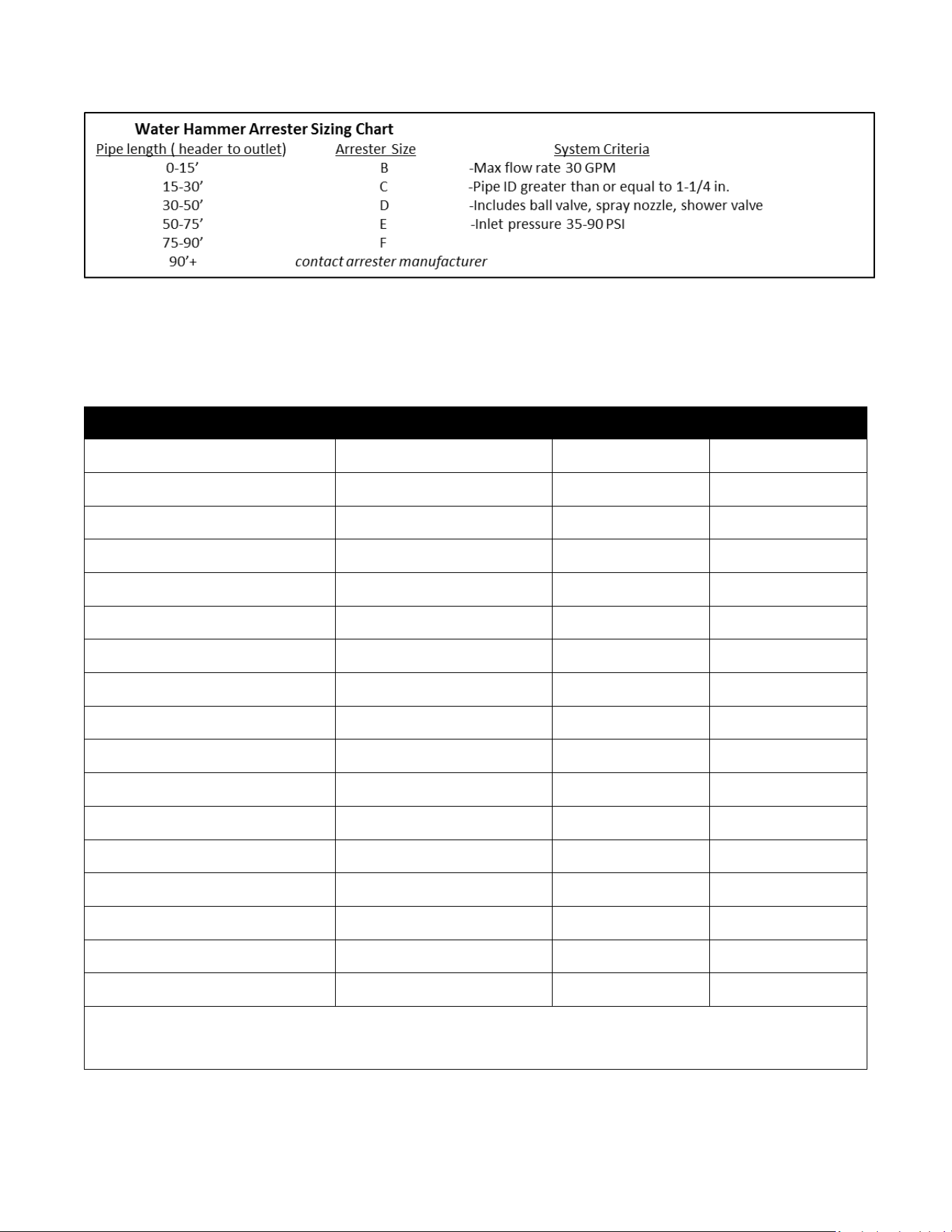
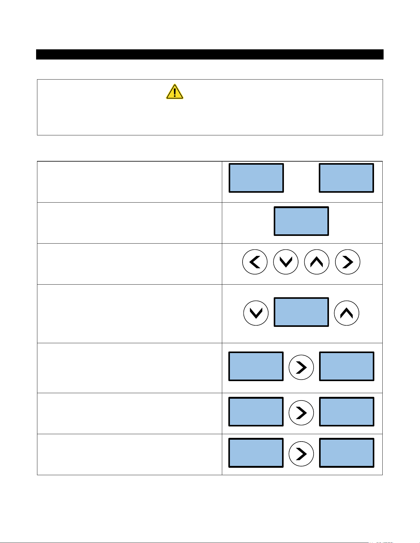
After verifying the heater has been purged of air (see above)
turn the circuit breaker/disconnect “ON” and observe the
start-up sequence on the display. The LCD screen will display
the SETPOINT TEMPERATURE in degrees F.
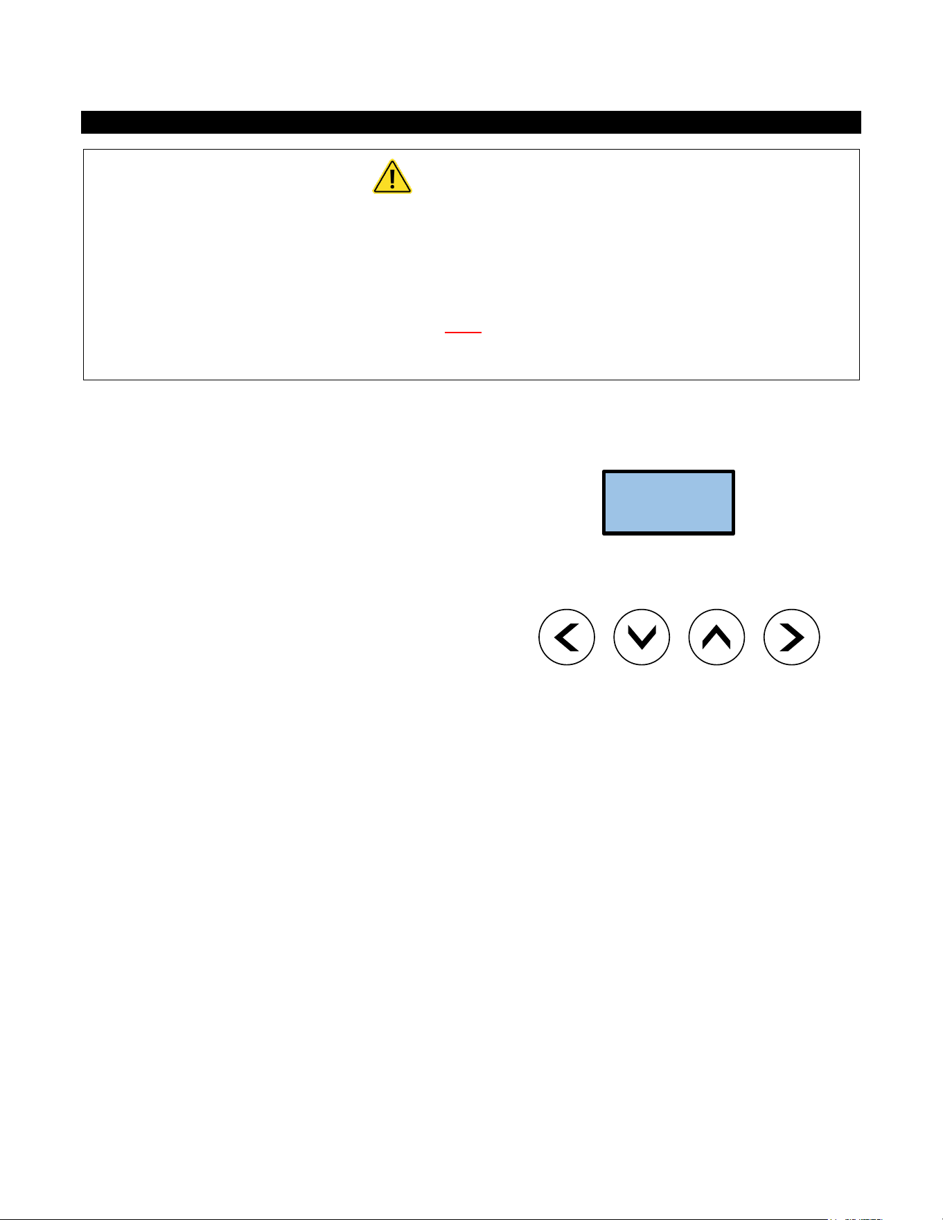
Below the display are 4 push buttons that are used to control
the function of the heater. Press the UP or DOWN buttons to
establish your desired temperature. Refer to the CONTROL
FEATURES section of this manual for additional information.
SETPOINT
TEMP 120F

11
Startup Process
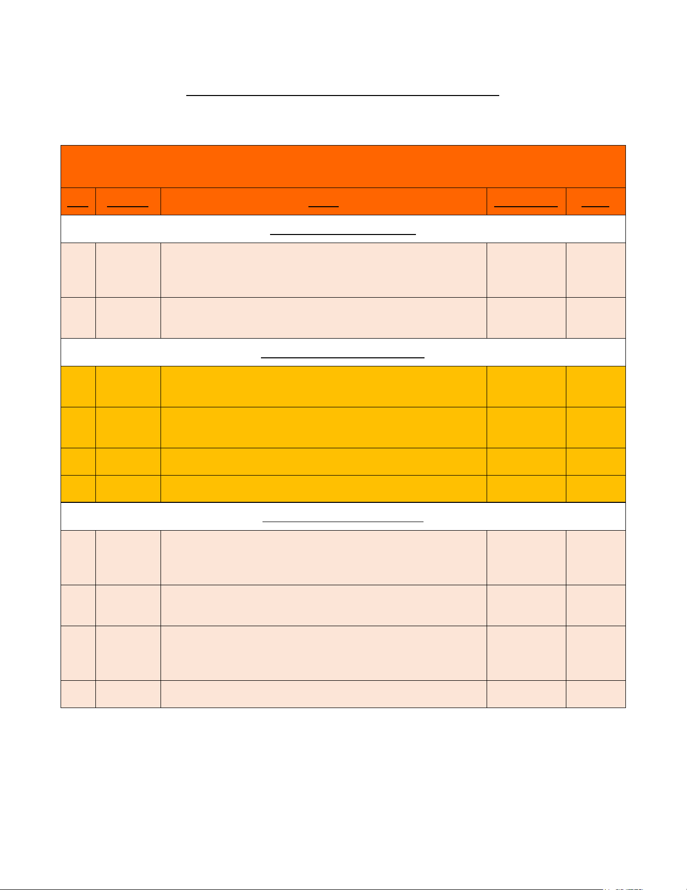
Plumbing Installation Checklist MUST BE FILLED OUT AND LEFT WITH WATER HEATER. MUST FLUSH WATER HEATER
FOR MINIMUM 5 MINUTES AT A MINIMUM.
Eemax Installation Checklist and Startup Procedure for SafeAdvantage and SpecAdvantage Water Heaters
Important - Read and fully understand all steps outlined below before proceeding. Failure to do so may damage the
water heater and void any warranty. Technical support is available at 1 (800) 543-6163
Plumbing Installation Checklist
Step
Category
Action
Confirmed By
Notes
1
Water
Heater is supplied with clean potable water
2
Water
Plumbing orientation is correct – water connections on the bottom - inlet on
the right, outlet on the left
3
Water
Ensure piping connections are not causing stress or torque on the inlet and
outlet fittings
4
Water
No leaks at water connection or in plumbing network
5
Water
Water pressure is between 40-90 PSI (min 35psi)
6
Water
Long pipe runs, high flow rates and valves closing can cause pressure spikes
(water hammer) above 1000 PSI. Consult piping schematic to ensure
arrestors and regulators are properly sized and located.
7
Water
(with power off) Open supply valves to water heater - run water through
fixtures to purge all air and debris in system. With water flowing, visually
inspect the clear element tubes between the inlet and outlet manifold to
ensure no air bubbles are present. (this may take several minutes)
8
Water
Using a flashlight, visually inspect heating chamber for any signs of leakage
9
Water
Ensure Water Heater will not freeze
10
Water
Ensure all local plumbing codes are met
11
Water
Plumbing installation correct and complete
Important - Read and fully understand all steps outlined below before proceeding. Failure to do so may damage the
water heater and void any warranty. Technical support is available at 1 (800) 543-6163
Electrical Installation Checklist
Step
Category
Action
Confirmed By
Notes
12
Power
(with power off) - Breaker and disconnect are of proper size and correctly
installed
13
Power
(with power off) - Wiring and conduit are of proper size and correctly
installed.
14
Power
(with power off) - Wiring connections at terminals are correct orientation,
tight, with no stray wire strands or pinched sheathing
15
Power
(with power off) - Proper ground,(not neutral) is clean, and tight
16
Power
(no water flowing, do not turn it on, close outlet water shut off valve if
uncontrolled environment-left hand side) Apply power - ensure voltage
and phasing is according to model rating
17
Power
Disengage power after voltage and phasing is confirmed (open outlet
shutoff valve if closed during step 14)
18
Power
Ensure all local electrical codes are met
19
Power
Electrical Installation correct and complete

12
Important - Read and fully understand all steps outlined below before proceeding. Failure to do so may damage the
water heater and void any warranty. Technical support is available at 1 (800) 543-6163
Startup Procedure and Checklist
Step
Category
Action
Confirmed By
Notes
20
Startup
Water requirements (Steps 1-11) are confirmed
21
Startup
Electrical requirements (Steps 12-19) are confirmed
22
Startup
Plumbing Codes and Electrical Codes are met and confirmed
23
Startup
(with power off) Open supply valves to water heater - run water through
fixtures to purge all air and debris in system. With water flowing, visually
inspect the clear element tubes between the inlet and outlet manifold to
ensure no air bubbles are present. (this may take several minutes)
Chugging or burping of water is also an indication of air
24
Startup
Turn off water flow at all fixtures, keeping water heater supply valves open
25
Startup
Apply power to water heater
26
Startup
Turn water flow on at fixtures
27
Startup
LCD display board is illuminated
28
Startup
Contactors engaged (audible click)
29
Startup
No error codes
30
Startup
Scroll through display (If display is locked, consult manual for unlock
procedure)
31
Startup
Adjust settings if needed. Note - Keep temperature setting as low as
possible for scald potential and minimizing abuse on the heater.
32
Startup
Confirm TURN-ON setting meets fixture flow rate
33
Startup
Confirm SETPOINT setting on display
34
Startup
Confirm ACTUAL TEMP output on display
35
Startup
If SETPOINT does not match ACTUAL TEMP then use the TEMPERATURE
RISE CHART in manual along with LOAD%, INLET TEMP and FLOW RATE on
display to determine the maximum theoretical output.
36
Startup
Shut water flow off at fixture
37
Startup
Power disengaged (audible)
38
Startup
Repeat startup steps 25-28 to ensure proper activation and performance
39
Startup
Water heater installed correctly and operating as designed
After all steps are completed, the heater is fully installed and ready for use.
13
Shutdown Process (Normal, Emergency, and Long Term)
Shut Down Procedure
Important - Read and fully understand all steps outlined below before proceeding. Failure to do so may damage
the water heater and void any warranty. Technical support is available at 1 (800) 543-6163
Step
Category
Action
Confirmed By
Notes
Normal Shut Down Procedure
1
Normal
Shut power off to unit in order of sequence - In-door (on-door)
disconnect (if applicable) local disconnect, main breaker - perform
lock out procedure per facilities requirements
2
Normal
Close applicable water valves - Inlet and outlet (water heater will
not be drained)
Emergency Shut Down Procedure
1
Emergency
Shut power off to unit In-door (on door) disconnect (if applicable) or
local disconnect
2
Emergency
Shut water valves off - inlet and outlet (water heater will not be
drained)
3
Emergency
Complete lock out procedures per facilities requirements
4
Emergency
Notify all parties involved that water heaters are shut down
Long Term Shut Down Procedure
1
Long Term
Shut power off to unit in order of sequence - Indoor disconnect (if
applicable) local disconnect, main breaker - perform lock out
procedure per facilities requirements
2
Long Term
Close applicable water valves - Inlet and outlet (water heater will
not be drained)
3
Long Term
Drain water heater through plumbing network, run compressed air
through the water heater to ensure the heater is completely
drained
4
Long Term
Lock out all applicable water valves per facilities procedures

14
MONITORING & PREVENTIVE MAINTENANCE
Recommended routine instrument readings and operation checking: Please note the instrument readings are
performed during water heater operation. No readings are required when the unit is not being used. Check the
following readings on the Remote display and ensure proper performance:
Inlet temperature
Temperature set point
Actual outlet temperature
Actual GPM
Error codes
Early warning signs of developing operational or equipment problems:
Based on the readings of 3A above water heater unit appears to be performing properly however there are
error codes.
Actual GPM appears to be lower than desired
Procedures for handling non-routine problems such as alarms, power failure, and component failure:
No alarms are built into the unit
Power failure will result in a non-operable system – restore power and startup unit per Start up process (2C)
Component failure will result in repeat error codes. Refer to manual page 16 for error codes and corrective
action
Preventative maintenance requirements: (PMR) Preventive maintenance requirements may impact other items of the
installation such as electrical supply and wiring, water piping and associated valves and controls.
Eemax water heaters are very low maintenance.
Ensure that the water heater is supplied with a clean potable, consistent water supply as outlined in the O+M.
Check filter screen or associated y-strainer or other pre-filters to ensure clear water supply within listed water pressure.
Ensure proper electrical supply as outlined within the O+M.
Perform PMR per site requirements not to exceed 90 days.
Maintenance inspection program: (MIP) Eemax water heaters are very low maintenance. Ensure PMR is completed
every 90 days.
Disable power to the unit via external disconnect or local disconnects. Per site lockout procedures open cabinet door
and visually inspect components for sings of damage associated with possible water leaks, excessive heat or external
factors that could impact the water heater and associated components.
Perform MIP per site requirements not to exceed 90 days.
15
CONTROL FEATURES
CAUTION
BEFORE USING THIS CONTROL, make sure all prior installation steps have been
properly completed, electrical power is on and water is present in the heater.
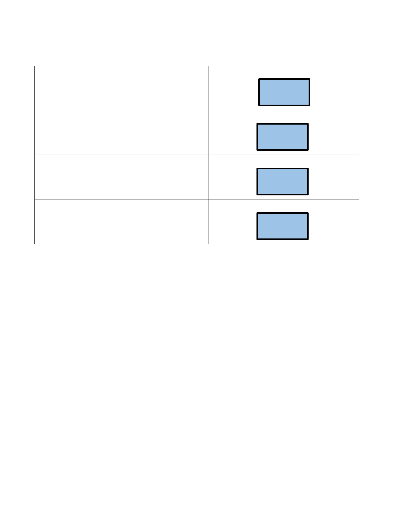
Push Button Flow Chart
1) The SETPOINT TEMP or ACTUAL TEMP screen can be
selected for display as the home screen. Either of these
screens will remain on the display when the backlight timer
expires.
OR
2) There is a 5-minute time delay built into the control.
Regardless of which screen is being displayed, after 5
minutes of inactivity, the display will revert to the SETPOINT
TEMP screen.
3) The 4 push buttons are used to control the operation of
the heater. The LEFT and RIGHT buttons shift the display
from one screen to another. The DOWN and UP buttons may
change the values within selected screens.
4) As an example, when the screen displays SETPOINT TEMP,
the desired hot water temperature will increase 1 degree for
each press of the UP button and decrease 1 degree for each
press of the DOWN button. Note that minimum and
maximum set point temperatures are established at the
factory.
5) The LEFT and RIGHT buttons shift the display from one
screen to another. From the INLET TEMP screen, one press
of the RIGHT button will shift the display to the SETPOINT
TEMP screen. INLET TEMP shows the actual temperature of
the water entering the heater.
6) From the SETPOINT TEMP screen, one press of the RIGHT
button will shift the display to the ACTUAL TEMP screen. This
shows the actual temperature of the water leaving the
heater.
7) Form the ACTUAL TEMP screen, one press of the RIGHT
button will shift the display to the LOAD PCT screen. This
shows the electrical power consumption as a percentage of
full power.
ACTUAL
TEMP 75F
SETPOINT
TEMP120F
SETPOINT
TEMP120F
SETPOINT
TEMP120F
SETPOINT
TEMP120F
INLET
TEMP 75F
ACTUAL
TEMP 75F
SETPOINT
TEMP120F
LOAD PCT
0% PWR
ACTUAL
TEMP 75F
16
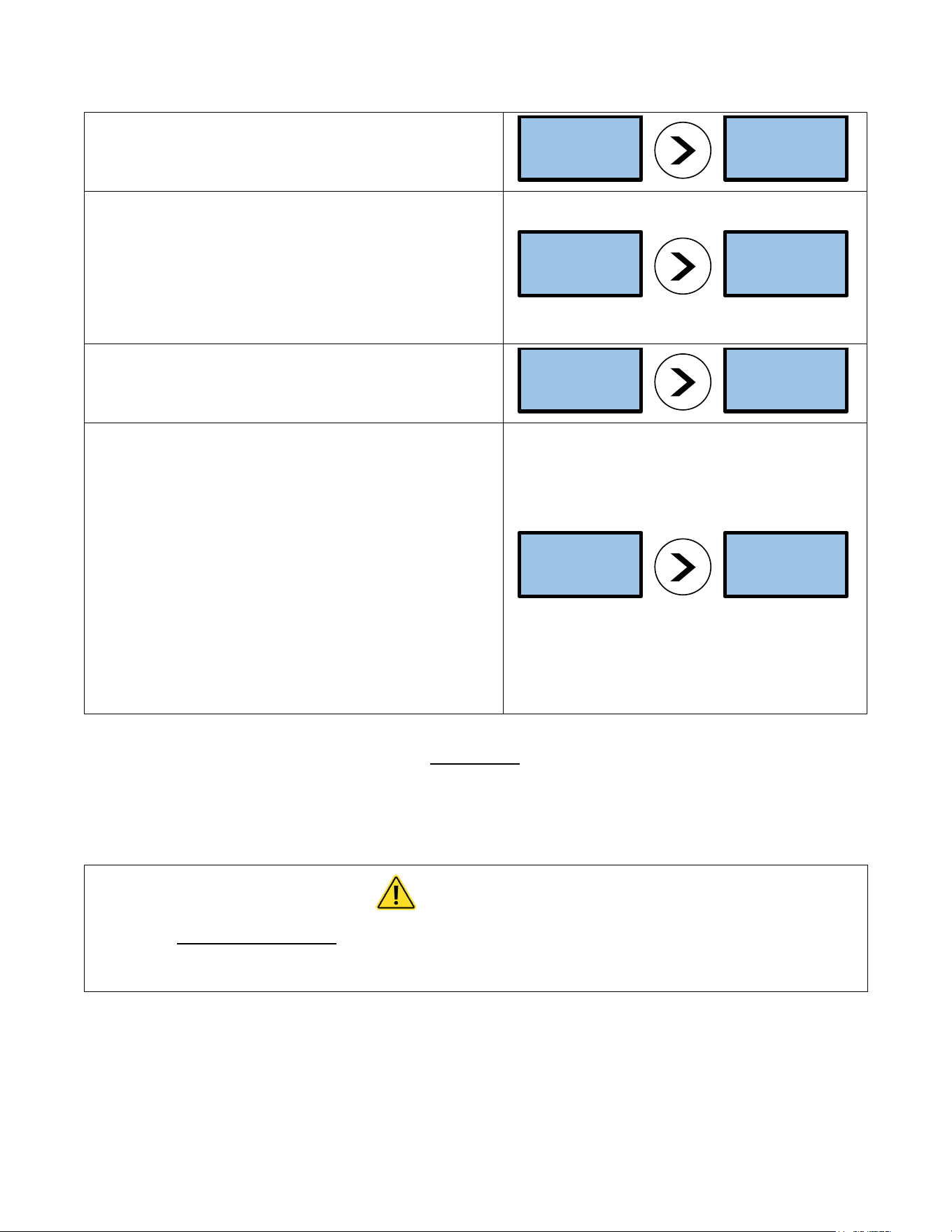
8) From the LOAD PCT screen, one press of the RIGHT button
will shift the display to the FLOWRATE screen. This shows the
rate of flow of water through the heater.
9) From the FLOWRATE screen, one press of the RIGHT
button will shift the display to the UNITS screen. This shows
the units of measure in either the ENGLISH or METRIC
systems. ENGLISH units are degrees Fahrenheit and gallons
per minute. METRIC units are degrees Celsius and liters per
second. Use the UP and DOWN buttons to select the desired
units of measure.
10) From the UNITS screen, one press of the RIGHT button
will shift the display to the SOFTWARE REVISION screen. This
shows the revision level of the software in the control.
11) From the SOFTWARE REVISION SCREEN, one press of the
right button will shift the display to the ERRORS screen. This
shows the error history of the heater. “0 ERRORS” means
that no errors have occurred.
If the heater has an error history of 4 errors: this history will
be displayed on the screen as shown. “CODE 1:E0” refers to
the first error and indicates it to be an E0 error. One press of
the UP button will show the second error as “CODE 2:E0”
error.
Continued pressing of the UP or DOWN buttons will scroll
through each of the errors in the history (in this case a total
of 4). ERRORS indicate an undesirable condition but will not
shut down the operation of the heater
Error Codes
E0: Excessive water flow detected
Corrective action: Using the OUTLET BALL VALVE, slowly reduce water flow until the desired temperature is achieved.
The temperature is proportional to the flow through the heater; the lower the flow, the higher the temperature and
vice versa.
CAUTION
Keep the INLET BALL VALVE fully “OPEN”. NEVER RESTRICT THE WATER FLOW USING
THE INLET VALVE.
E1: Inlet temperature too hot to generate heat
FLOWRATE
??? GPM
LOAD PCT
0% PWR
UNITS
ENGLISH
FLOWRATE
??? GPM
SOFTWARE
20131218
UNITS
ENGLISH
1 ERROR
CODE1:F0
SOFTWARE
20131218
17
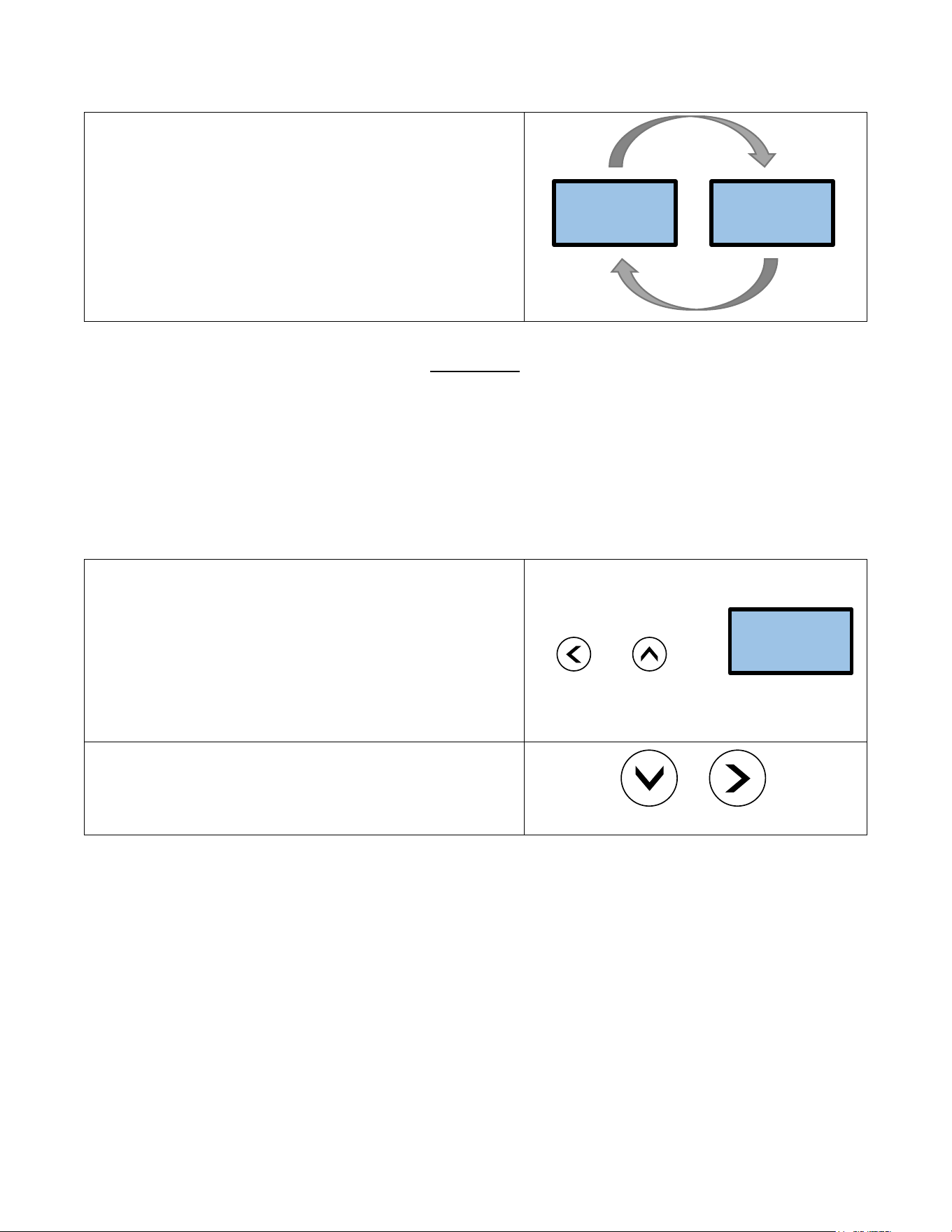
12) FAULTS are communicated through the LCD display. The
display will switch from the SETPOINT screen to the FAULT
screen and back again every 3 seconds. FAULTS indicate an
undesirable condition and will immediately shut down the
operation of the heater. If faults are appearing on your heater
call Eemax Technical Support for assistance.
Fault Codes
F0: Outlet thermistor out of range
F1: No change in water temperature detected
F2: Dry fire detected - Optical Sensor Tripped
F3: Excessive dry fire occurrences detected
F4: Inlet thermistor out of range
13) The security of the heater settings is provided by pressing
and holding the LEFT and UP buttons for 3 seconds to lock the
buttons. Once locked, the buttons have no function. Press and
hold the same LEFT and UP buttons for 3 seconds to unlock the
buttons.
The security status can be checked at any time by pressing any
one button. If the system is locked, the screen will display
“BUTTONS LOCKED”.
[ + ] =
14) The display can be turned off or on. Press and hold the
DOWN and RIGHT buttons for 3 seconds. If the display is off, it
can be turned on by pressing and holding the same DOWN and
RIGHT buttons for 3 seconds.
+
1 ERROR
CODE1:F0
SOFTWARE
20131218
BUTTONS
LOCKED

18
TROUBLESHOOTING PROCEDURES
If you need any assistance from our Technical Service Department, make sure you can identify this water heater by
having the model number and serial number.
Model No. ______________________________
Serial No. ______________________________
Call 203-267-7890
TOLL FREE: 1-800-543-6163
Eemax.S[email protected]
PROBLEM
POSSIBLE CAUSES
Action
IF TRUE
Proceed to Action
IF FALSE
Proceed to Action
Unit does
not power
on
Main Power issue
A1
Check main power supply voltage is
within +/- 5% of nominal. Check
breaker and wire size.
A2
Provide the correct
supply voltage to the
heater
Blown Fuse
A2
Check all fuses for continuity
A3
Check voltages and
elements, replace fuse
Transformer
overload
A3
Check circuit breaker on 24V control
transformer
A4
Check voltages and for
failed PCB, Contactors-
reset transformer
Printed circuit
board (PCB)
A4
Verify main PCB is plugged in at P16
Replace PCB
Check connection, and
reset connector
Display
ERROR E1
Water temperature
entering heater is
above SETPOINT
A5
Verify supply water supply
temperature is below set point.
Note - Heater will automatically
engage when incoming water drops
below set point.
A6
Adjust supply
temperature below set
point
Loose PCB
connection or
pinched wire
A6
Check PCB connection at P7 and
check wire routing
A7
Check connection, and
reset connector
Inlet thermistor
failure
A7
Check thermistor for proper
placement in well
Replace thermistor
Re-seat thermistor in
well
Display
FAULT F0
Outlet thermistor
out of range
A8
Check PCB connection at P7 and
check wire routing
A9
Check connection, and
reset connector
Outlet thermistor is
damaged or wire is
cut
A9
Check thermistor, wire, or
connector for damage
Replace thermistor
A10
Heater is frozen
A10
Verify supply and feed lines are not
frozen
Un-freeze heater and check
functionality
Display
FAULT F1
No change in water
temperature
detected
A11
Verify change in temperature by
checking ACTUAL TEMP vs INLET
TEMP
Lower flow rate to allow
heater to operate in range
of capability
A12
Thermistor failure
A12
Follow actions A5-A7
A13
Thermal trip at
ECO/ Damaged
wire
A13
Power off, Using a multimeter check
continuity at PCB P17 pins 1 and 3.
Check all wires for loose connection
A14
No continuity verifies a
thermal trip. Shut down
power and allow to
cool. Verify connector
is seated

19
Flow rate is too
high
A14
Check LOAD PCT for 100% load
Reduce flow rate, heater is
operating outside of
capability
A15
Element failure
A15
Power off, Using a multimeter check
continuity at between red and black
wires at each element chamber
A16
No continuity- replace
heater element. Check
water quality
Heating Elements
not modulating
A16
Verify SSR/Triac functionality by
checking current draw off each
SSR/Triac by means of an amp
clamp. Also verify signal wires are
connected from PCB P2, P3, and P4.
No current draw-
replace SSR/ Triac
Display
FAULT
Ambient light is
causing the optical
(overheat) sensors
to trip.
A17
Unit is to be operated with the
cover on or (if NEMA equipped)
door closed when power is applied
to the unit.
A18
Close door, or reinstall
cover
Air is present in the
heating chamber
A18
Verify air is not present in the
system by checking for a red led
light on the heating chamber. Look
between the black manifolds into
the clear tube sections for air
bubbles.
Remove air by installing an
air scrubber prior to heater,
or flushing system
thoroughly before use.
Check all wire connections
Replace light sensor
board
Loose /cut wire to
optical sensors
A19
Verify 5VDC is present on the last
optical sensor in the chain by using a
multimeter set for dc voltage at the
connector P12 with one meter lead
on the red wire and the other on the
black wire.
Check A17 and A18 again
Call Eemax for support
Display
FAULT F3
Multiple dry fire
conditions
detected (FAULT
F2) more than 3
times
A20
Recheck actions A17-A19. Shut
down power and restart.
Replace main PCB and
light sensor boards
Display
FAULT F4
Inlet thermistor out
of range
A21
Verify inlet thermistor is properly
seated in thermal well
Verify inlet temperature is
not below freezing, above
set point temperature, or
heater is piped backwards
Replace thermistor
inlet or outlet or both
No heat
Turn-on flow rate
not satisfied
A22
Toggle through display to verify
FLOWRATE and TURN-ON
Increase water flow rate
above TURN-ON setting
Check wiring to
flowmeter.
Display states
FLOW ???
A23
Power off unit, and verify no faults
are found. Verify flow meter harness
is seated in terminal P12 on the
main PCB and at flow meter PCB
Call Eemax for support,
firmware reload may be
required
If faults found
reference above
Note: Error code history is not self-clearing. Unit keeps track of past errors. Error codes do not necessarily mean
there is a current error.
20
TECHNICAL SUPPORT
TECHNICAL SUPPORT FORM
PERFORM STEPS BELOW BEFORE CALLING TECHNICAL SUPPORT
1 (800) 543-6163
WATER HEATER
MODEL # ____________________________________ SERIAL # ____________________________________
Inlet Water Pressure ____________________ Inlet Water Temperature ____________________
Incoming Voltage
L1 ____________
L2 ____________
L3 ____________
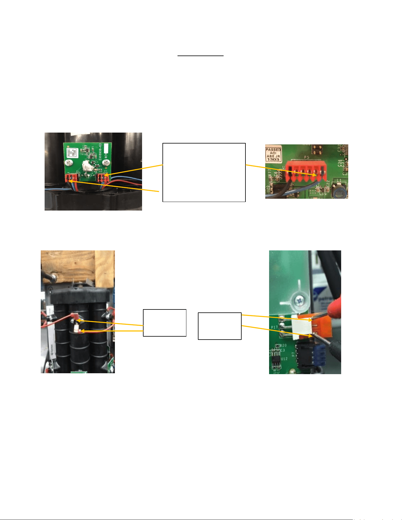
Testing Elements
Amp draw on each heating element,
place clamp on each red wire on inlet
side of contactor.
E1 ______ E2 ______ E3 ______
E4 ______ E5 ______ E6 ______
Testing Elements
Ohm out heating elements: place
#1 lead on 1 terminal on right side
of SSR (FIG 1); place #2 lead (FIG 2)
on the matching numbered red
wire on outlet side of contactor
GPM FLOW RATE _____________
LOAD PERCENTAGE _____________
FIG 1
FIG 2
Wire #1 TAG
21
Testing Points
Testing optical sensors:
Ohm out optical sensors: find jack plug p5 on circuit board and place #1 lead on the blue wire, then place #2 lead on
the on the blue wire on the back right optical board. Move #2 lead to each blue wire on optical boards to verify
continuity. Repeat with black wire.
Test ECO’s (electric cut offs):
To check ECO’S, on jack plug P17 put leads between top and bottom contact. If no continuity, then check across each
ECO
Lead placement: TEST BLUE
AND BLACK SEPERATELY. PUT
1 LEAD ON BLUE WIRE ON P5
PLUG THEN OTHER LEAD
GOES TO EACH BLUE WIRE
ALONG OPTICAL SENSORS.
REPEAT WITH BLACK WIRE.
Test points
for individual
ECO
Test points to
check all
ECOs

22
Configuration Parameters Loading Guide
Record and document any error codes on display,
inserting USB will erase all code history. Then
Disconnect power from the heater by turning off the
circuit breaker.
ERROR CODES:
Your heater may or may not be installed in a NEMA
4/4X cabinet. For units with the NEMA cabinet,
remove the 5 mounting screws to remove the cover.
Plug in the USB
Turn on the power
23
Home screen will appear first.
The heater has recognized the USB drive
CNF file has been successfully loaded-IF “CNF ERR” is
displayed, try removing reseating the USB into the slot.
It is now OK to turn off the power, remove the USB and
replace the cover
ACTUAL
TEMP 73F
USB CONN
90 73F
USB CONN
CNF READ
USB CONN
90 73F
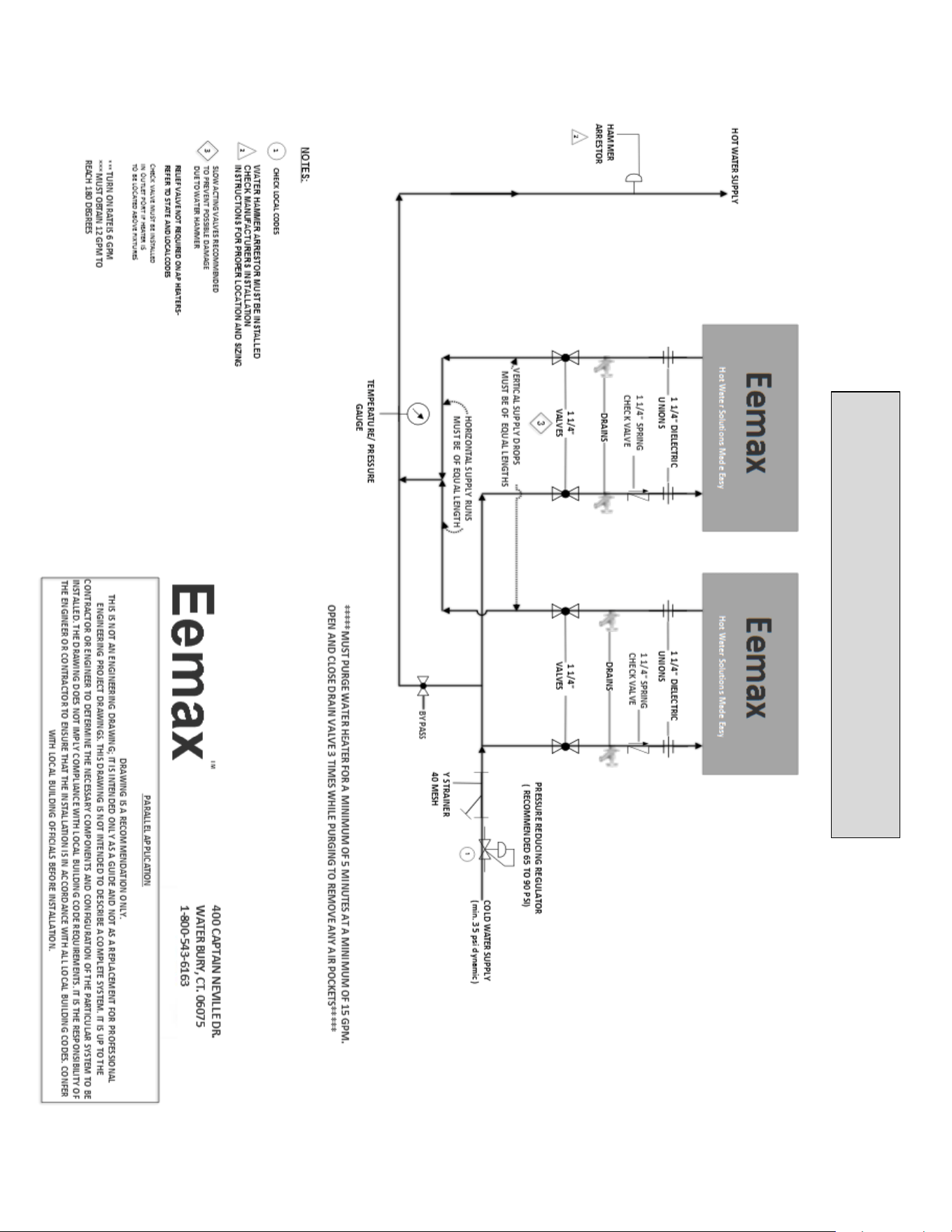
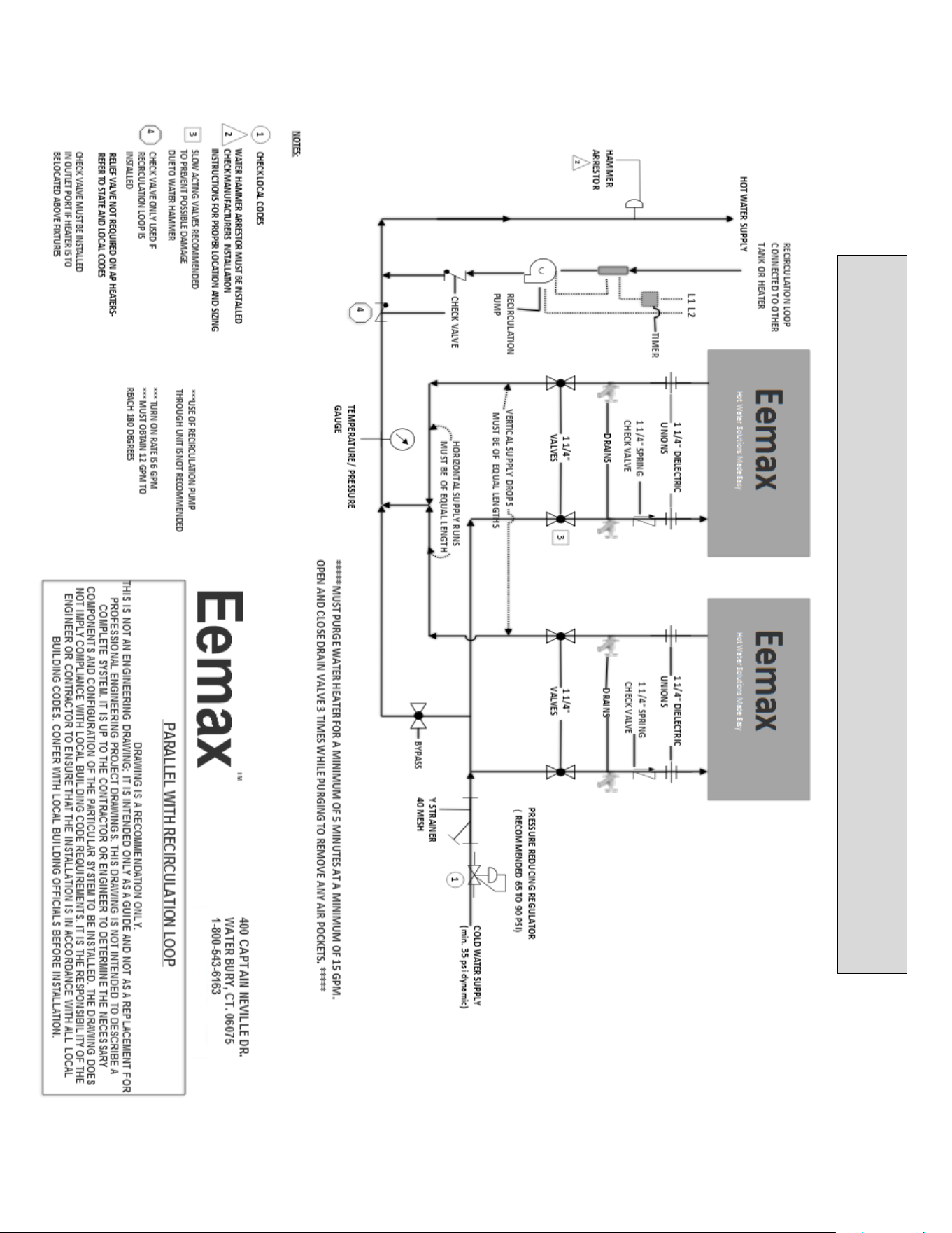
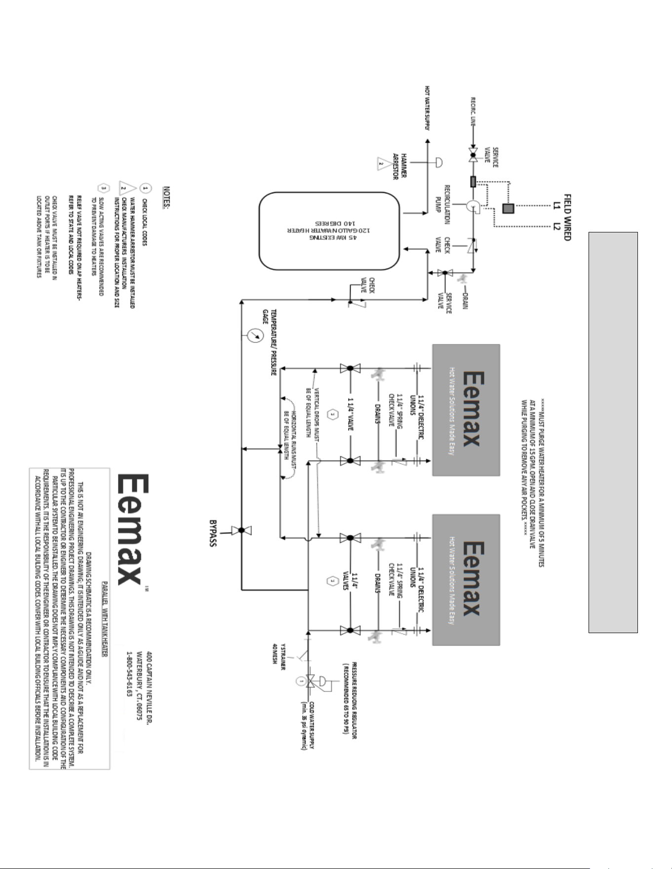
24
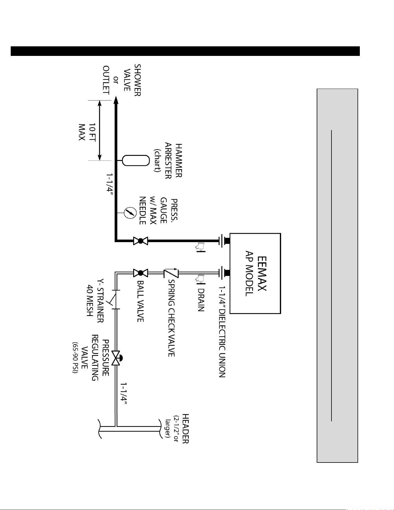
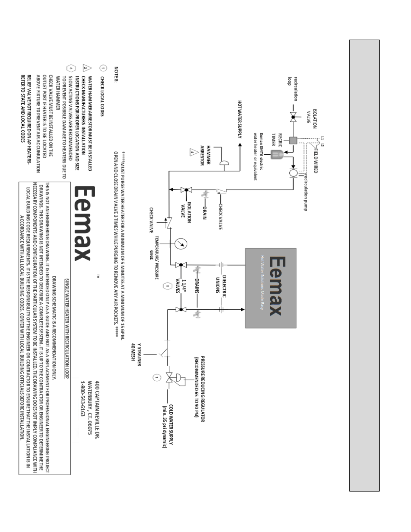
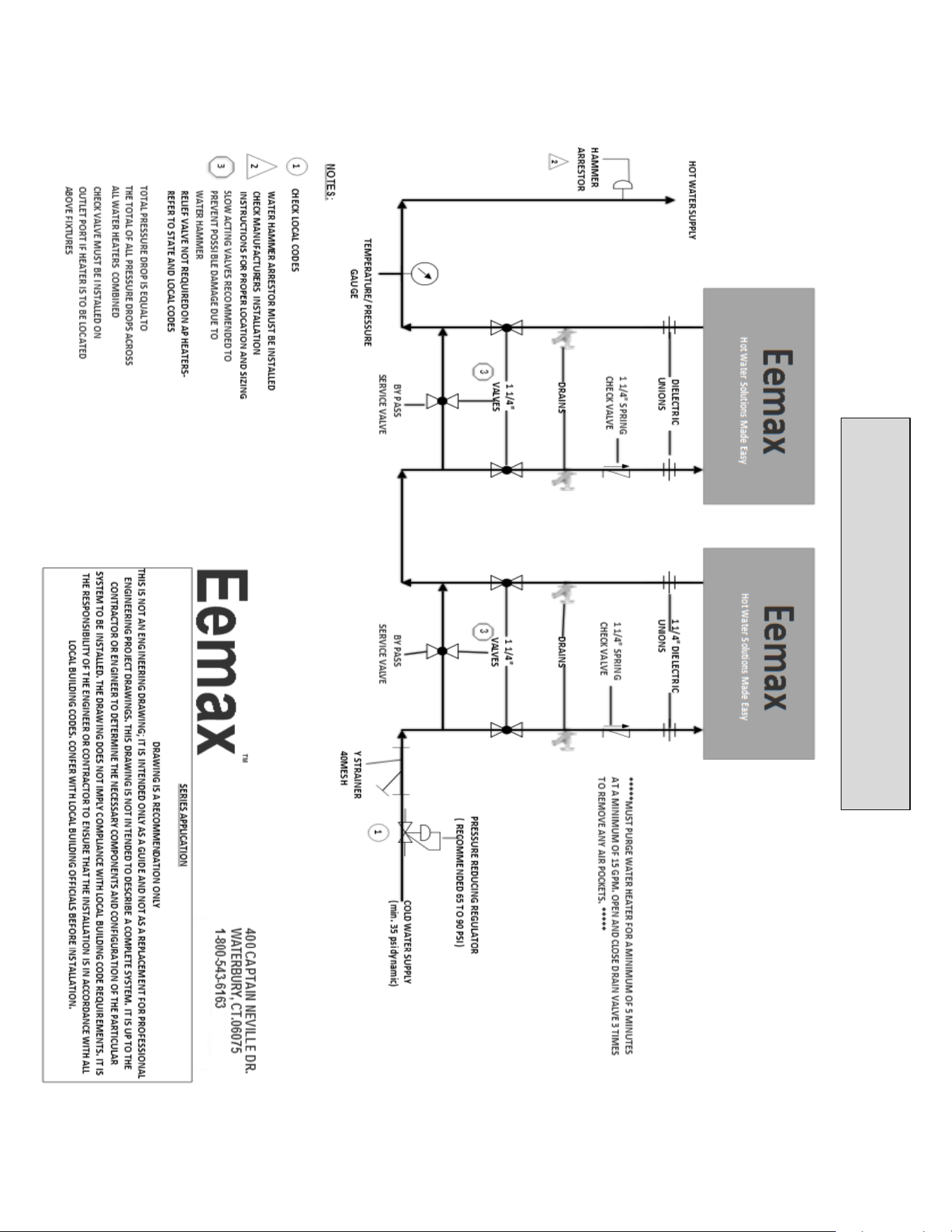
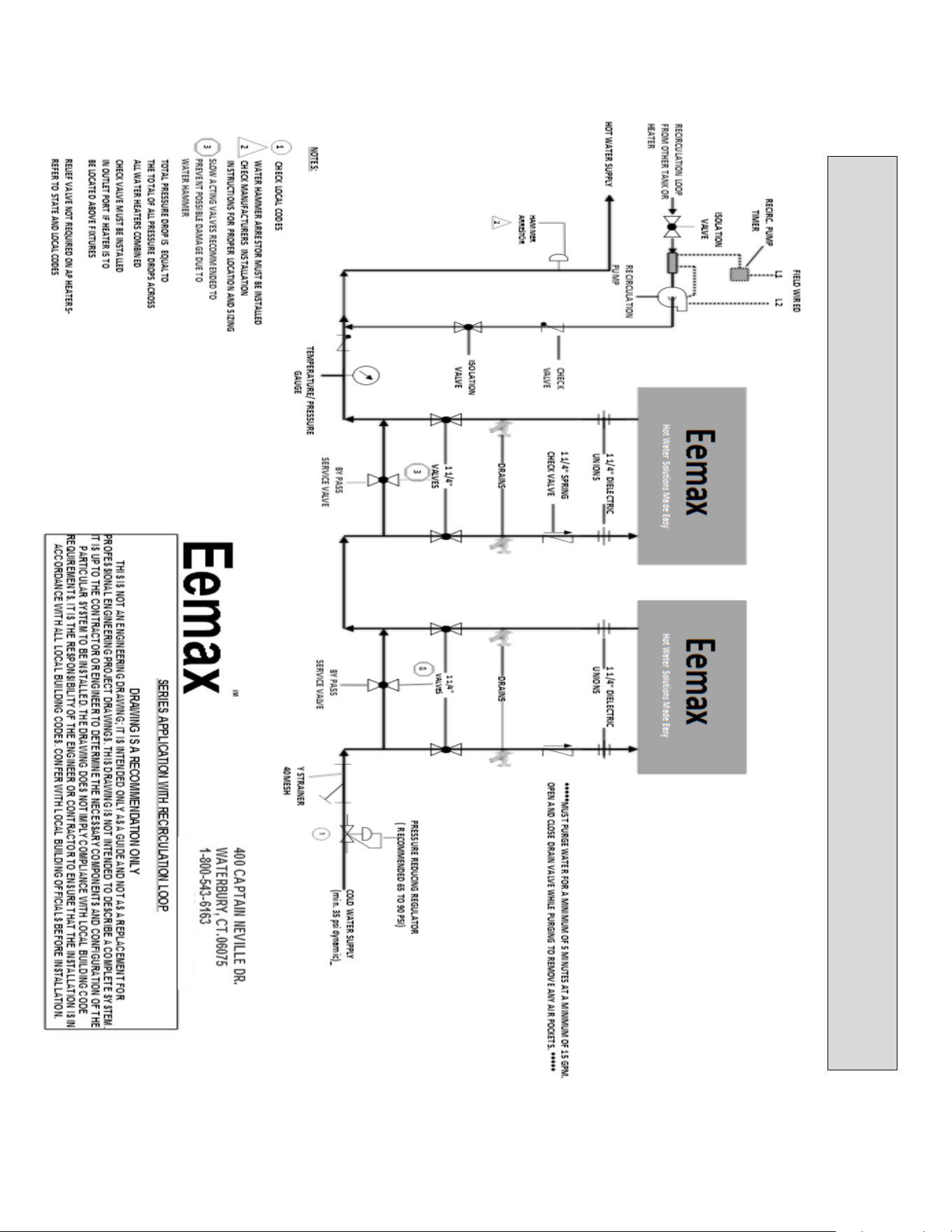
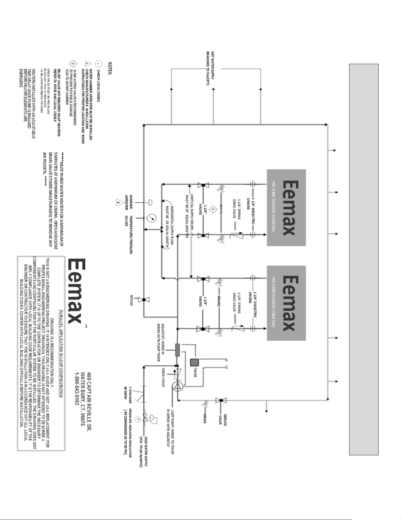
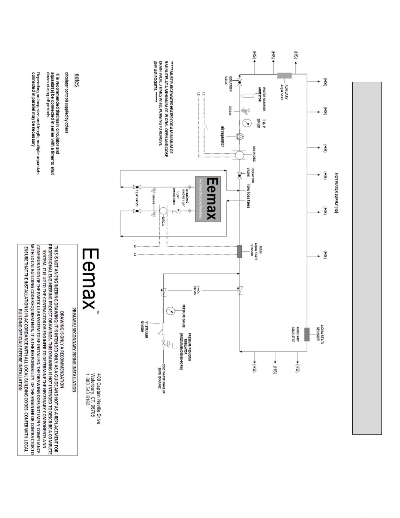
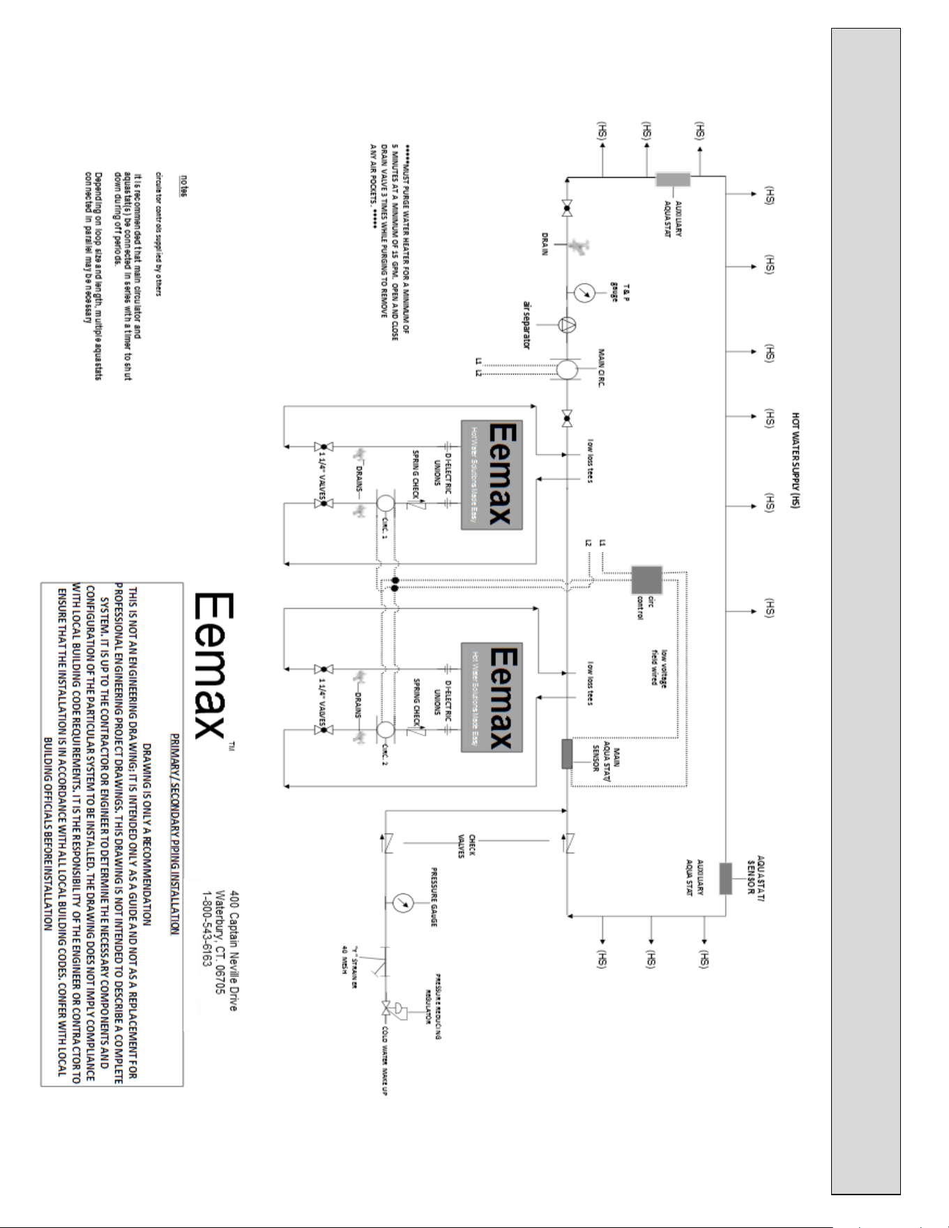
APPLICATIONS SCHEMATICS
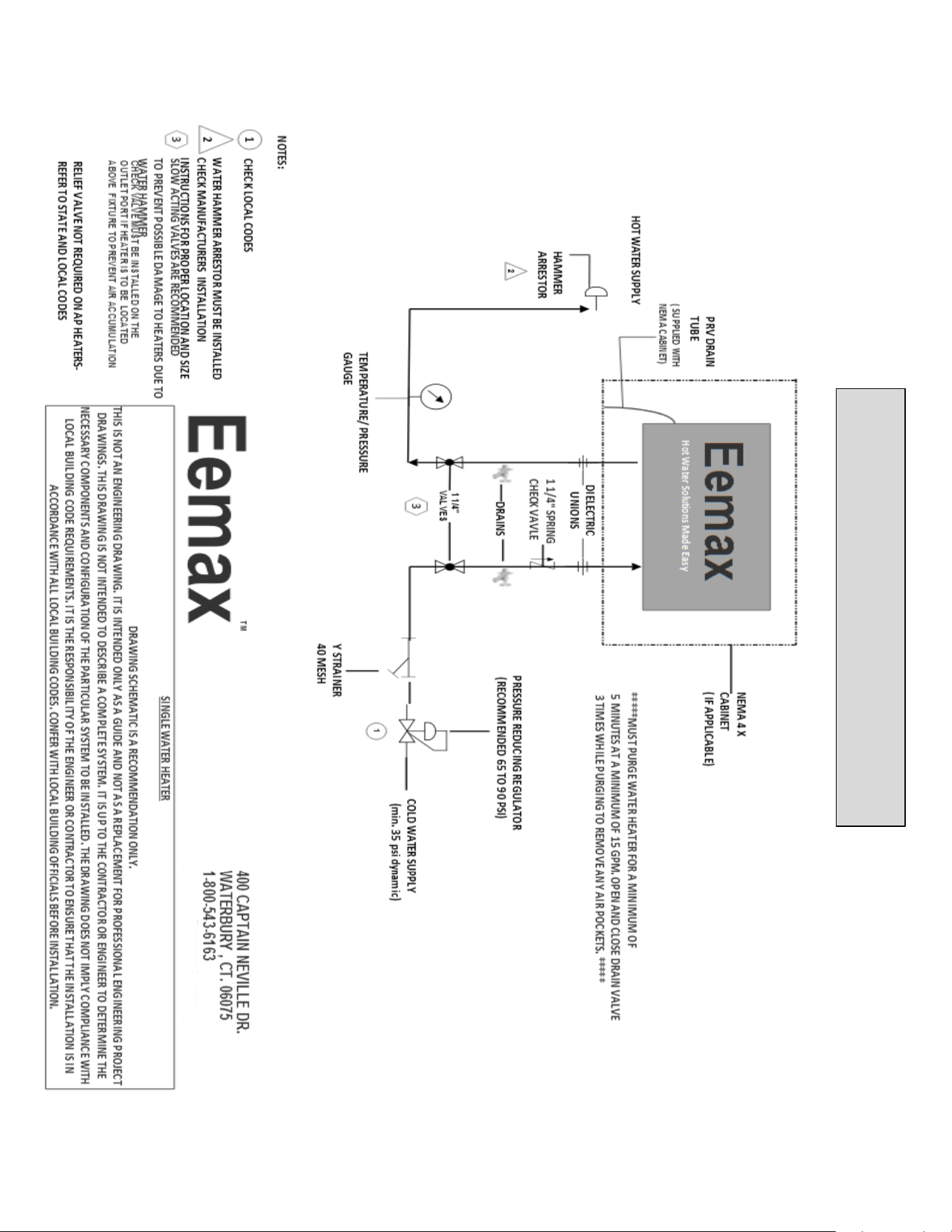
TYPICAL SAFETY SHOWER or POINT OF USE INSTALLATION
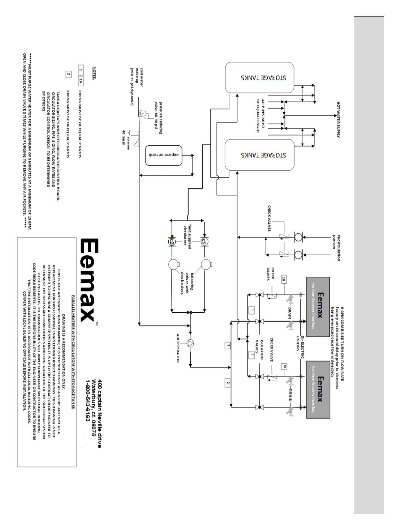
42
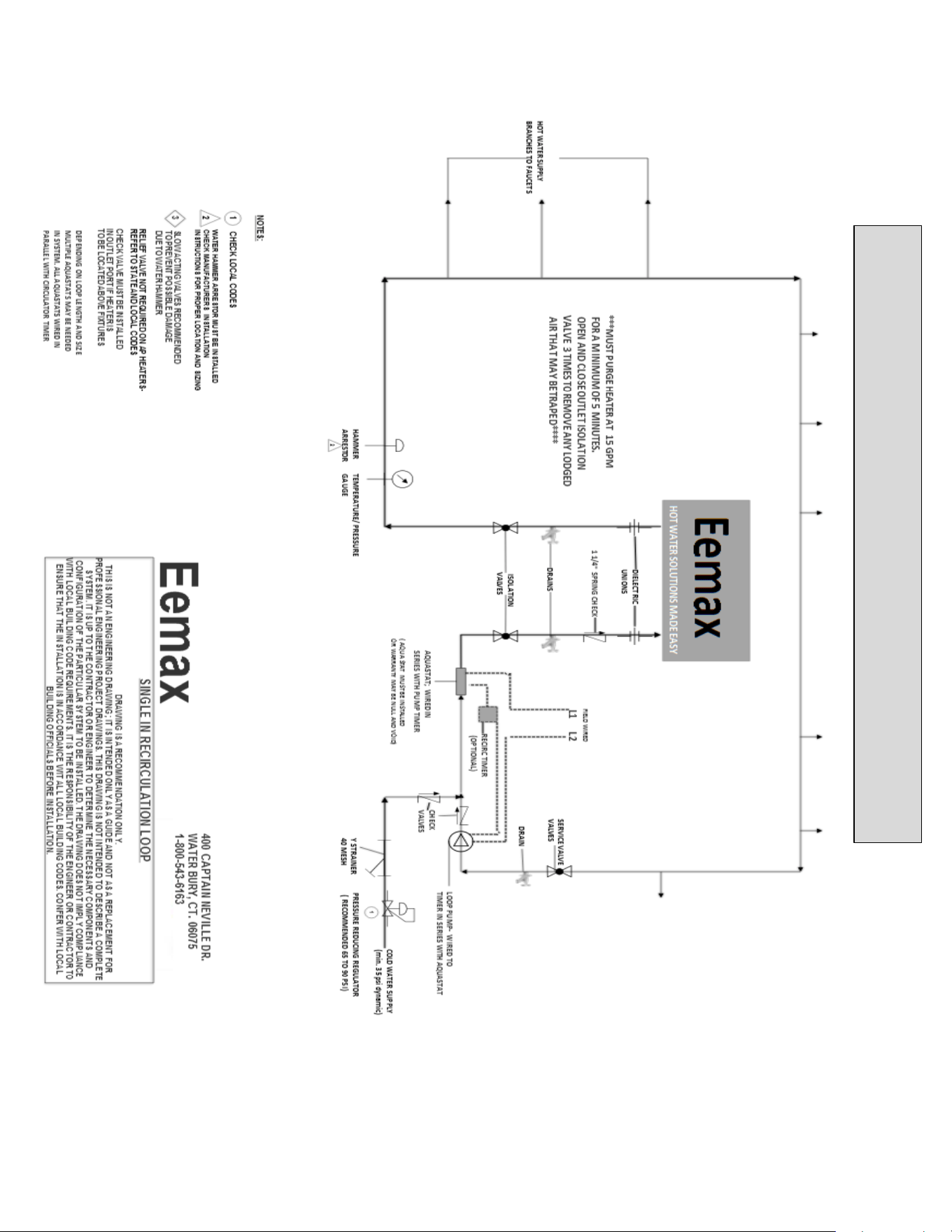
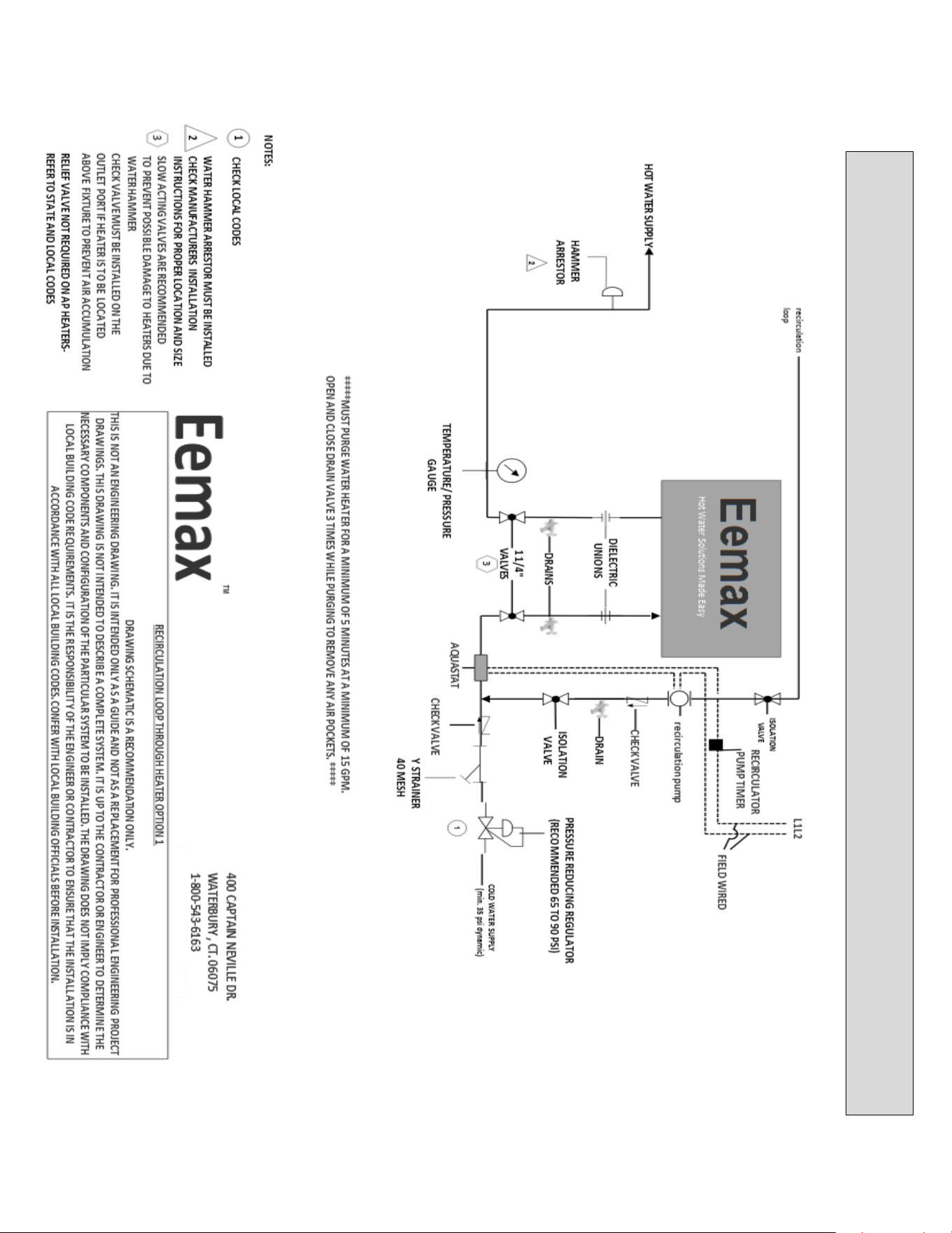
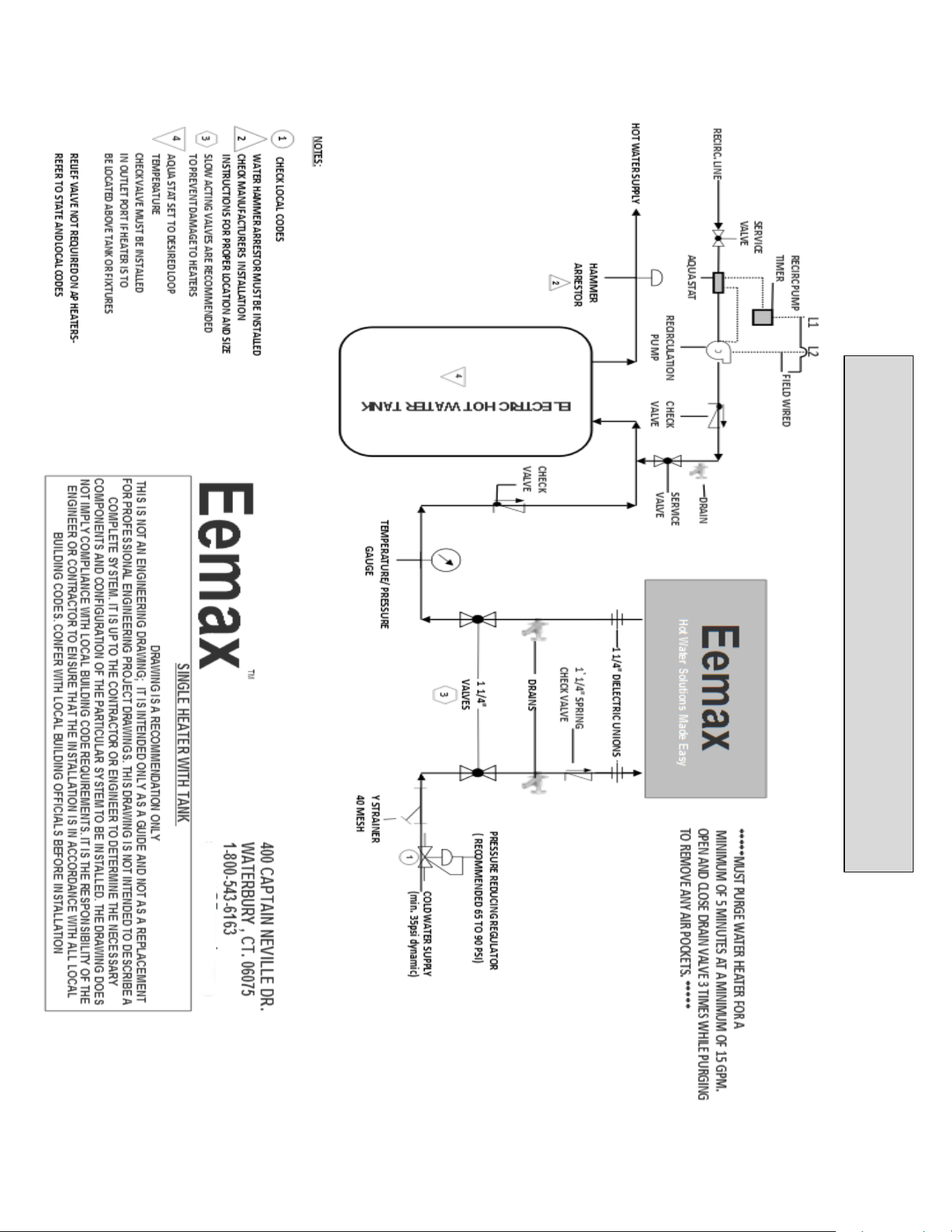
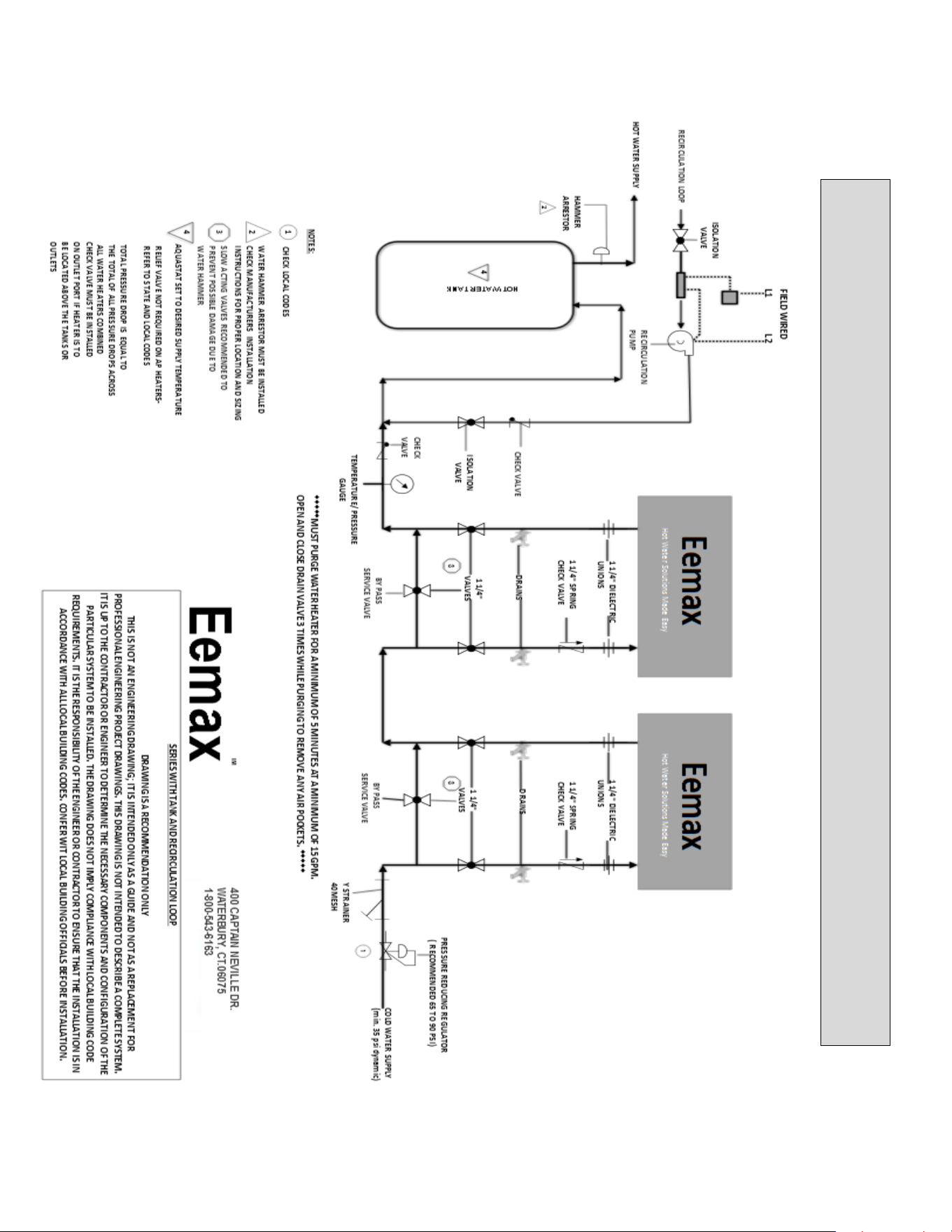
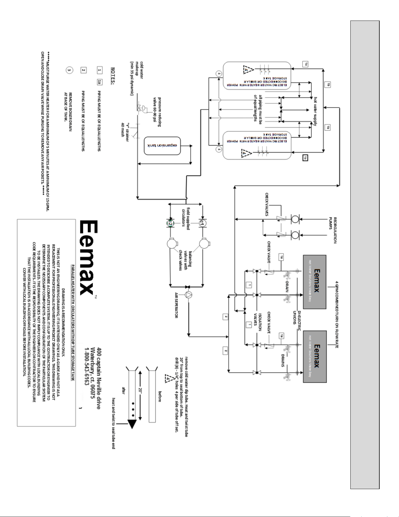
STORAGE TANKS WITH HIGH FLOW DEMAND CIRCULATORS/LOW FLOW DEMAND HEATER
INSTALLATION
45
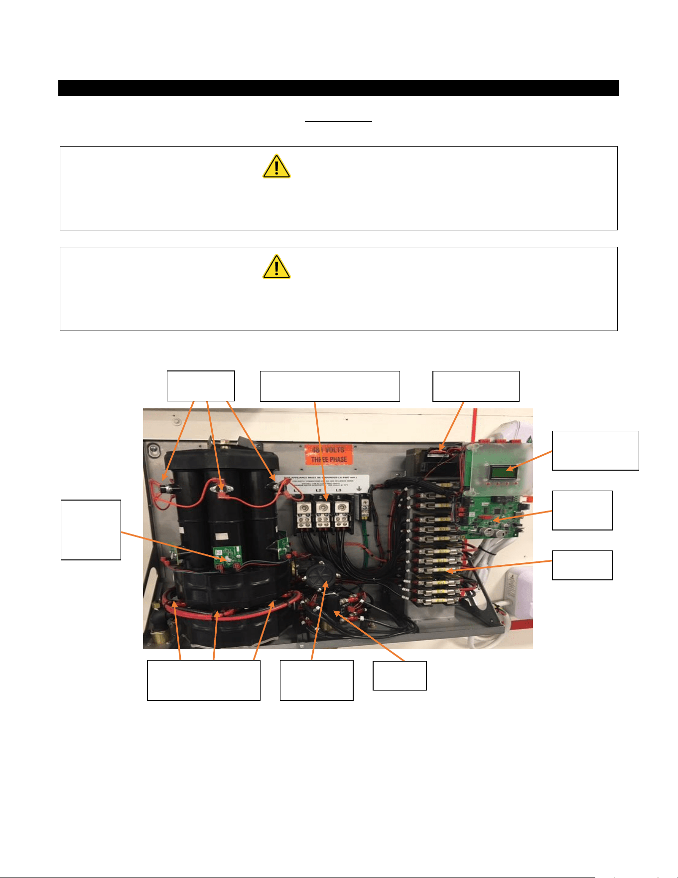
REPAIRS AND OPTIONS
Repair Parts
WARNING
Service and repairs are to be performed by licensed electricians or qualified
servicemen.
WARNING
Before attempting any repairs to the heater, make sure that the electrical breaker is
“off” and confirm that there is no voltage at the heater.
* HEATING ELEMENT ASSEMBLY CONSISTS OF ONE HEATER CORE AND WIRE ELEMENT(S)
** FLOW METER KIT CONSISTS OF PADDLE WHEEL, DOWEL PIN, O RING AND 4 MOUNTING SCREWS.
ECO’s
Electrical Connections
Transformer
LED Display
Board
Optical
Sensor
Boards
Control
Board
Fuses
Heating Element
Assembly*
Flow
Meter **
SSR’s

46
Repair Parts (continued)
Triacs Assembly replaced by SSR
Model
Number
Model
Number
Suffix
Element Number
Assembly
Flow Meter
Assembly
(inc board)
Master
Display
Board
Transformer
Fuses
SSR Assemble (incl. 3)
ECO
Assembly
Optical
Board
Assembly
208V
AP032208
EX77000-8.12 B02
EX78000-00
EX08300-00
EX08303-07
EX198
EX78009-00
EX278A-Kit
EX78001-00
AP032208
EE
EX77000-8.12 A04
EX78000-00
EX08300-00
EX08303-07
EX198
EX78009-00
EX278E-Kit
EX78001-00
AP032208
S
EX77000-8.12 B00
EX78000-00
EX08300-00
EX08303-07
EX198
EX78009-00
EX278D-Kit
EX78001-00
AP036208
EX77000-7.20 B02
EX78000-00
EX08300-00
EX08303-07
EX08200-11
EX78009-00
EX278A-Kit
EX78001-00
AP036208
EE
EX77000-7.20 A04
EX78000-00
EX08300-00
EX08303-07
EX08200-11
EX78009-00
EX278E-Kit
EX78001-00
AP036208
S
EX77000-7.20 B00
EX78000-00
EX08300-00
EX08303-07
EX08200-11
EX78009-00
EX278D-Kit
EX78001-00
AP041208
EX77000-6.33 B02
EX78000-00
EX08300-00
EX08303-07
EX08200-11
EX78009-00
EX278A-Kit
EX78001-00
AP041208
EFD
EX77000-6.33 A04
EX78000-01
EX08300-00
EX08303-07
EX08200-11
EX78009-00
EX278E-Kit
EX78001-00
AP041208
S
EX77000-6.33 B00
EX78000-00
EX08300-00
EX08303-07
EX08200-11
EX78009-00
EX278D-Kit
EX78001-00
AP054208
EX77000-4.81 B02
EX78000-00
EX08300-00
EX08303-07
EX198
EX78009-00
EX278A-Kit
EX78001-00
AP054208
EFD
EX77000-4.81 A04
EX78000-01
EX08300-00
EX08303-07
EX198
EX78009-00
EX278E-Kit
EX78001-00
AP054208
S
EX77000-4.81 B00
EX78000-00
EX08300-00
EX08303-07
EX198
EX78009-00
EX278D-Kit
EX78001-00
AP064208
EX77000-4.06 B04
EX78000-01
EX08300-00
EX08303-07
EX08200-11
EX78009-00
EX278A-Kit
EX78001-00
AP064208
EFD
EX77000-4.06 A04
EX78000-01
EX08300-00
EX08303-07
EX08200-11
EX78009-00
EX278E-Kit
EX78001-00
AP064208
S
EX77000-4.06 B00
EX78000-01
EX08300-00
EX08303-07
EX08200-11
EX78009-00
EX278D-Kit
EX78001-00
480
AP036480
EX77000-19.2 B02
EX78000-00
EX08300-00
EX08303-05
N/A
EX78009-00
EX278A-Kit
EX78001-00
AP036480
EE
EX77000-19.2 A04
EX78000-01
EX08300-00
EX08303-05
N/A
EX78009-00
EX278E-Kit
EX78001-00
AP036480
S
EX77000-19.2 B00
EX78000-00
EX08300-00
EX08303-05
N/A
EX78009-00
EX278D-Kit
EX78001-00
AP039480
EX77000-17.7 B02
EX78000-00
EX08300-00
EX08303-05
N/A
EX78009-00
EX278A-Kit
EX78001-00
AP039480
EE
EX77000-17.7 A04
EX78000-01
EX08300-00
EX08303-05
N/A
EX78009-00
EX278E-Kit
EX78001-00
AP039480
S
EX77000-17.7 B00
EX78000-00
EX08300-00
EX08303-05
N/A
EX78009-00
EX278D-Kit
EX78001-00
AP048480
EX77000-14.4 B02
EX78000-00
EX08300-00
EX08303-05
N/A
EX78009-00
EX278A-Kit
EX78001-00
AP048480
EFD
EX77000-14.4 A04
EX78000-01
EX08300-00
EX08303-05
N/A
EX78009-00
EX278E-Kit
EX78001-00
AP048480
S
EX77000-14.4 B00
EX78000-00
EX08300-00
EX08303-05
N/A
EX78009-00
EX278D-Kit
EX78001-00
AP054480
EX77000-12.8 B04
EX78000-00
EX08300-00
EX08303-08
EX08100-07
EX78009-00
EX278A-Kit
EX78001-00
45

47
AP054480
EFD
EX77000-12.8 A04
EX78000-01
EX08300-00
EX08303-08
EX08100-07
EX78009-00
EX278E-Kit
EX78001-00
AP054480
S
EX77000-12.8 B00
EX78000-00
EX08300-00
EX08303-08
EX08100-07
EX78009-00
EX278D-Kit
EX78001-00
AP063480
EX77000-18.2 B04
EX78000-01
EX08300-00
EX08303-08
EX198
EX78009-00
EX278A-Kit
EX78001-00
AP063480
EFD
EX77000-18.2 A04
EX78000-01
EX08300-00
EX08303-08
EX198
EX78009-00
EX278E-Kit
EX78001-00
AP063480
S
EX77000-18.2 B00
EX78000-01
EX08300-00
EX08303-08
EX198
EX78009-00
EX278D-Kit
EX78001-00
AP072480
EX77000-19.2 B04
EX78000-01
EX08300-00
EX08303-08
EX198
EX78009-00
EX278A-Kit
EX78001-00
AP072480
EFD
EX77000-19.2 A04
EX78000-01
EX08300-00
EX08303-08
EX198
EX78009-00
EX278E-Kit
EX78001-00
AP072480
S
EX77000-19.2 B00
EX78000-01
EX08300-00
EX08303-08
EX198
EX78009-00
EX278D-Kit
EX78001-00
AP096480
EX77000-14.4 B04
EX78000-01
EX08300-00
EX08303-08
EX198
EX78009-00
EX278A-Kit
EX78001-00
AP096480
EFD
EX77000-14.4 A04
EX78000-01
EX08300-00
EX08303-08
EX198
EX78009-00
EX278E-Kit
EX78001-00
AP096480
S
EX77000-14.4 B00
EX78000-01
EX08300-00
EX08303-08
EX198
EX78009-00
EX278D-Kit
EX78001-00
AP108480
EX77000-12.8 B04
EX78000-01
EX08300-00
EX08303-08
EX198
EX78009-00
EX278A-Kit
EX78001-00
AP108480
EFD
EX77000-12.8 A04
EX78000-01
EX08300-00
EX08303-08
EX198
EX78009-00
EX278E-Kit
EX78001-00
AP108480
S
EX77000-12.8 B00
EX78000-01
EX08300-00
EX08303-08
EX198
EX78009-00
EX278D-Kit
EX78001-00
AP126480
EX77000-10.97 B04
EX78000-01
EX08300-00
EX08303-08
EX08200-11
EX78009-00
EX278A-Kit
EX78001-00
AP126480
EFD
EX77000-10.97 A04
EX78000-01
EX08300-00
EX08303-08
EX08200-11
EX78009-00
EX278E-Kit
EX78001-00
AP126480
S
EX77000-10.97 B00
EX78000-01
EX08300-00
EX08303-08
EX08200-11
EX78009-00
EX278D-Kit
EX78001-00
AP144480
EX77000-9.6 B04
EX78000-01
EX08300-00
EX08303-08
EX08200-13
EX78009-00
EX278A-Kit
EX78001-00
AP144480
EFD
EX77000-9.6 A04
EX78000-01
EX08300-00
EX08303-08
EX08200-13
EX78009-00
EX278E-Kit
EX78001-00
AP144480
S
EX77000-9.6 B00
EX78000-01
EX08300-00
EX08303-08
EX08200-13
EX78009-00
EX278D-Kit
EX78001-00
600
AP130600
EX77000-16.4 B04
EX78000-01
EX08300-00
EX08303-06
EX08200-09
EX78009-00
EX278A-Kit
EX78001-00
AP130600
EFD
EX77000-16.4 A04
EX78000-01
EX08300-00
EX08303-06
EX08200-09
EX78009-00
EX278E-Kit
EX78001-00
AP130600
S
EX77000-16.4 B00
EX78000-01
EX08300-00
EX08303-06
EX08200-09
EX78009-00
EX278D-Kit
EX78001-00
AP150600
EX77000-14.4 B04
EX78000-01
EX08300-00
EX08303-06
EX08200-09
EX78009-00
EX278A-Kit
EX78001-00
AP150600
EFD
EX77000-14.4 A04
EX78000-01
EX08300-00
EX08303-06
EX08200-09
EX78009-00
EX278E-Kit
EX78001-00
AP150600
S
EX77000-14.4 B00
EX78000-01
EX08300-00
EX08303-06
EX08200-09
EX78009-00
EX278D-Kit
EX78001-00
46
48
Options
Optional Class 1 Division 2
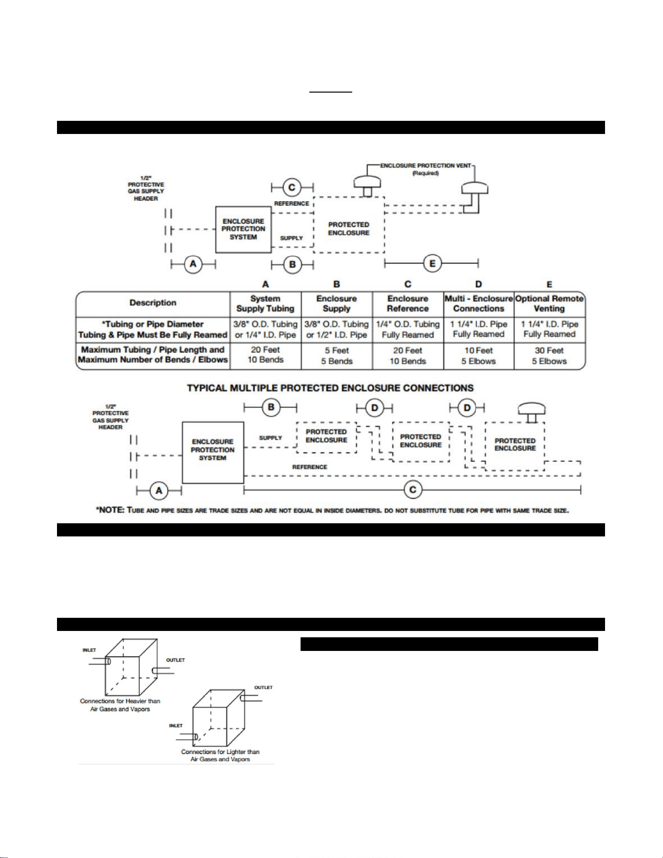
Establishing Connections Sizes, Lengths & Bends
Typical Single Protected Enclosure Connections
Helpful Hints
To ensure adequate protective gas flow to the protected enclosure(s), all piping and tubing must be fully reamed.
Precautions must be taken to prevent crimping and other damage to protective gas piping and tubing.
When protecting multiple enclosures with a single enclosure protection system, the enclosures must be connected
in series from the smallest to the largest to ensure adequate protective gas flow.
Determining Enclosure Inlet & Outlet Connection Locations
Helpful Hints
If flammable gases are lighter than air, the inlet connection to each
enclosure must enter near a bottom corner. The outlet connection, for
the required enclosure protection vent or piping to an adjacent
protected enclosure, must exit near an extreme opposite top corner. If
flammable gases are heavier than air, inlet and outlet connections must
be reversed. In all cases, the most prevalent gas must determine the
location of inlet and outlet connections.
49
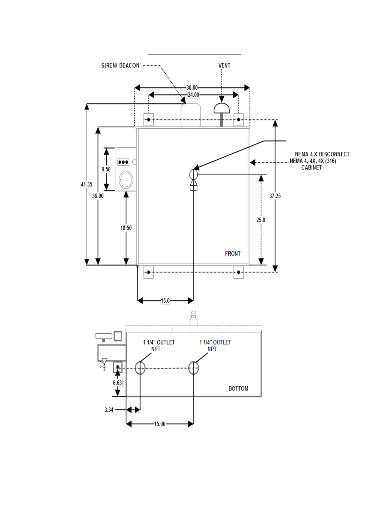
NEMA Cabinet 4, 4X, 4X (316)
50
Electrical Supply Requirements
General Wiring Requirements
WARNING
THIS DEVICE CONTAINS ELECTRICAL PARTS
WHICH CAN CAUSE SHOCK OR INJURY.
All electrical connections, conduit and fittings on the protected
enclosure must be suitable for the hazardous location in which
they are installed. In addition, all conduit and wire must be
installed in accordance with NEC as required and all relevant plant
and local codes. Note: Do not use seals on conduit used as a
protected "wireway" to supply protective gas to adjacent
protected enclosures. The same conduit can be utilized for both
electrical and pneumatic service to an adjacent protected
enclosure(s), provided the conduit is oversized to allow a
minimum free clearance equal to or larger than the pipe size
required between multiple enclosures.
Enclosure Power Requirements
The protected enclosure(s) electrical power source must originate
from a circuit breaker or fused disconnect suitable for the
hazardous location in which it is installed. The switch must be
located within fifty (50) (15.2 m) feet of the protected enclosure(s)
and the protection system and be properly marked.
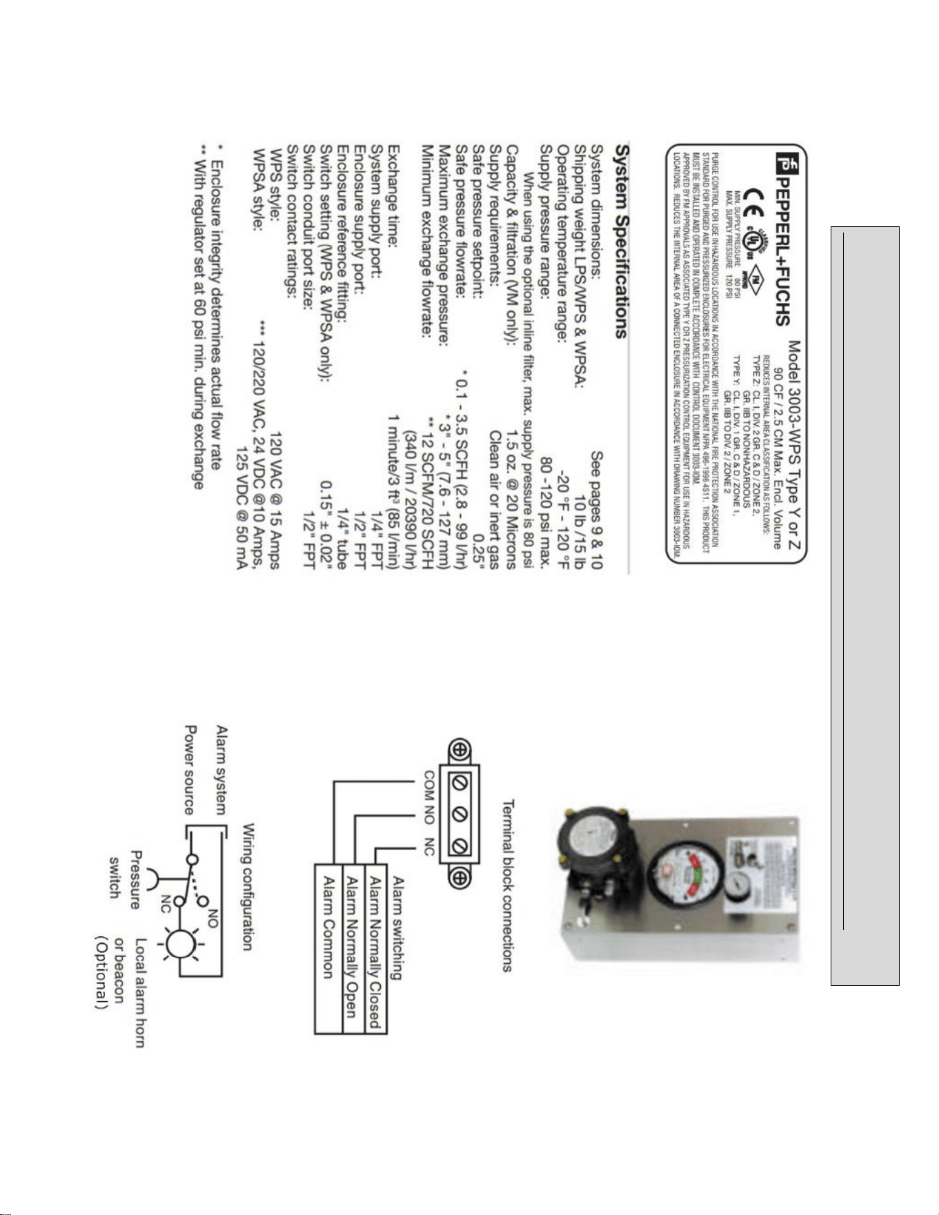
Alarm Signal Requirements
The WPSA style pressure switch requires a 120 VAC power supply
in addition to the alarm signal. The WPS and WPSA Style system
alarm signal may originate from the protected enclosure if the
alarm signal is disconnected by the protected enclosure's circuit
breaker or fused disconnect as stated in Enclosure Power
Requirements above.
The protected enclosure(s) alarm signal power may also originate
from outside of the protected enclosure. In this application, the
protected enclosure may be used as a "wireway" to pass alarm
signal wiring from the power source to the alarm device, if the
wiring is isolated and properly labeled. In addition, appropriate
conduit seals must be provided outside of the protected enclosure
separately.
Important Note
NFPA 496 requires the use of an alarm or an indicator to detect
the loss of safe enclosure pressure. In addition, the NFPA 496
requires that if an indicator alone is utilized, a protective gas
supply alarm must also be installed between the last valve in
the protective gas supply and the protected enclosure.
Therefore, the protective gas supply to all LPS Style systems
must be equipped with the above mentioned protective gas
supply alarm. Exception: Systems utilizing an EPSK or GPSK
enclosure pressure loss alarm switch accessory will satisfy the
above mentioned NFPA requirement.
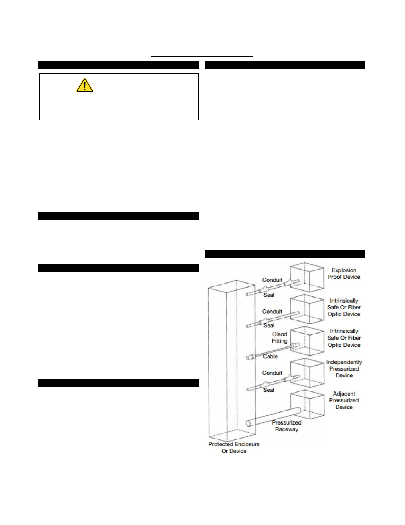
Typical Enclosure Wiring Methods
In a general sense, protected enclosures should be wired similar
to explosion proof enclosures, in accordance with Article 500 of
the National Electric Code - NFPA 70.
Single conductor wiring should be placed in rigid metal conduit,
seal-flex conduit or other mediums approved for use in the
hazardous location surrounding the protected enclosure.
Additionally, NFPA 496 requires the use of approved seals on all
pressurized enclosure conduit wiring entries, in accordance with
NFPA 70. Furthermore, the use of an approved seal is simply the
most practical way to prevent excessive leakage through conduit
connections.
However, while explosion proof enclosures require conduit seals
on all cable entries, in accordance with NFPA 70, other methods of
sealed cable entries that are suitable for hazardous locations can
be used, such as compression glands.
In conclusion, there are two primary goals. First, the installer
should ensure that all associated wiring and cable is protected by
pressurization or other means, such as explosion proof conduit or
intrinsic safety barriers. Secondly, the installer should ensure that
all associated conduit and wireways are sealed to conserve
protective gas, unless they are used to supply protective gas to
other enclosures or devices.
Typical Enclosure Wiring Connections
51
Conduit Installation
Electrical Conduit
1. Choose the location for the enclosure's electrical conduit
connection(s) based on the requirements on page 49,
"Electrical Supply Requirements".
2. Drill and deburr enclosure conduit fitting holes in the
protected enclosure. Mount the fittings.
3. Determine appropriate route for the enclosure electrical
and power alarm signal conduit
4. Measure, cut and thread conduit, check conduit fit to
ensure proper seating. Fully ream all conduit.
5. Install conduit and tighten all fittings to fitting
manufacturer’s specifications. Secure conduit to appropriate
structural supports as required.
6. Seal all conduit with an approved compound prior to
operation of the protection system.
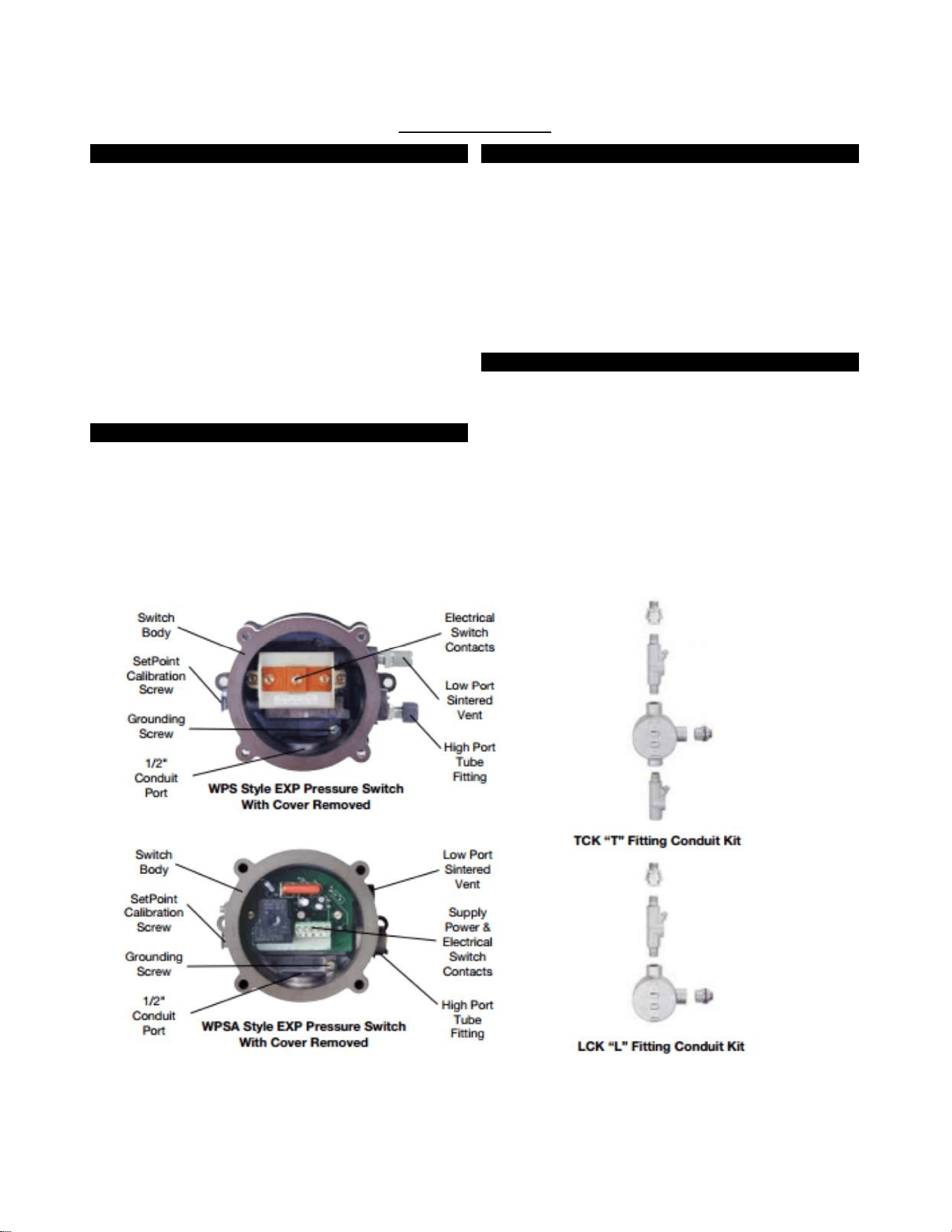
WPS Style Conduit Connection Parts
WPS & WPSA style systems provide electrical contacts for audible
or visual alarm devices that signal a loss of protected enclosure
pressure. They are calibrated to alarm at 0.15” (3.8 mm) for Class
I applications. The switches are suitable for hazardous (classified)
outdoor locations. Wiring must be installed with a seal and
conduit: fittings suitable for the area. Alarm circuit power may be
derived from the protected enclosure power source or an
intrinsically safe alarm signal source. All associated alarm devices
must be protected by suitable means (explosion proof, purged or
intrinsically safe).
WPS Style Conduit Connection Parts
Fitting Kits Can Be Bebco Furnished
1. For EXP pressure loss alarm switch connected to an
enclosure mounted alarm, one (1) LCK (L fitting Conduit Kit)
or equivalent conduit elbow, coupling and seal fittings.
2. For EXP pressure loss alarm switch connected to a remote
mounted alarm, one (1) TCK (T fitting Conduit Kit) or
equivalent conduit tee, coupling and seal fittings.
3. One (1) lot 150# rating 1/2" galvanized or aluminum pipe.
Helpful Hint
It may be impractical to pour all electrical conduit seals prior to
installation in the field. However, all conduit connections must
be sealed for proper testing and operation of the Enclosure
Protection System. Therefore, the use of temporary seals such as
duct seal or masking tape for bench or shop testing, prior to final
field installation may be used.

52
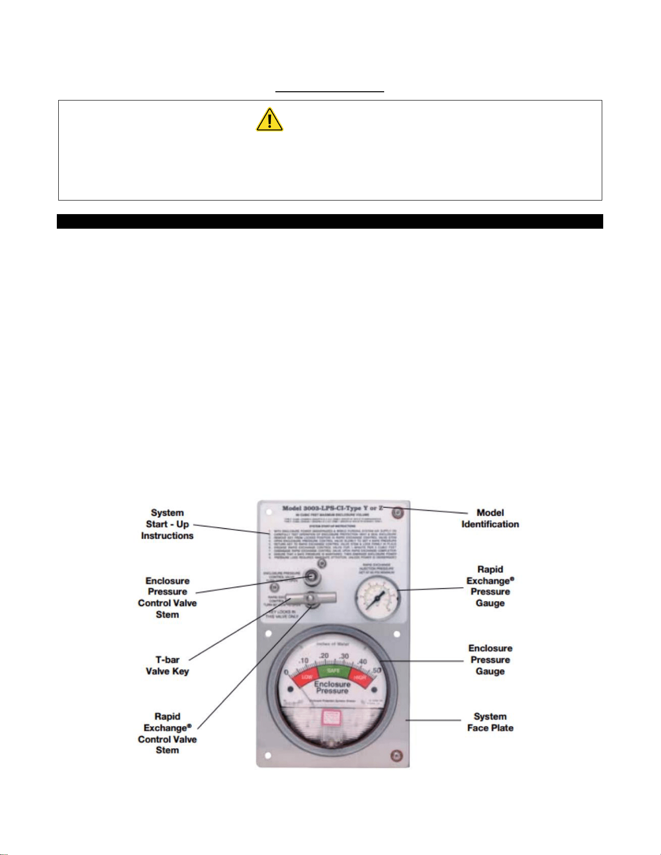
Set-up Procedure
Helpful Hints
“Safe" pressure, for purposes of this manual, is defined
as a minimum .25 inch (6.4 mm) of water column.
Regulator may be in the locked position upon arrival. To
adjust regulator, pull handle to outward position.
Carefully insert T-bar valve key to align valve stem tip of
both valves. Practice locking and unlocking key in the
RECV valve stem. Practice and familiarization of this
process should ease operation of the system.
To test the vent's operation, gently prod the vent flapper
open with a soft pointed object, (example: eraser end of
a pencil) ensuring that the vent valve works freely. On
vertically configured vents, this can be accomplished
from within the protected enclosure. Side mounted -90
configured vents can be tested by removing the conduit
plug at the bottom of the mounting tee. Multiple
operations require only one test per day if enclosure is
not opened or left unattended.
Important Notes
The Rapid Exchange® Control Valve and the Enclosure
Pressure Control Valve are both operated by utilizing the
removable T-bar Valve Key supplied with the system. The
purge system is shipped with the T-bar Valve Key locked in
the Rapid Exchange® Control Valve stem. To remove the T-
bar Valve Key, wrap your index and middle finger around
the T-Bar and place your thumb firmly against the system
face plate. Pull the T-bar Valve Key straight out firmly. This
will unlock and free the T-bar Valve Key for use in the
Enclosure Pressure Control Valve stem. When Set-Up or
Operating procedures are complete. Replace the T-bar
Valve Key in the Rapid Exchange® Control Valve stem and
push in firmly to lock in position. THE T-BAR VALVE KEY
LOCKS IN THE RAPID EXCHANGE® CONTROL VALVE STEM
ONLY.
Operators must secure wrist or stop watch to manually
time Exchange Cycle for all applications.
Pepperl+Fuchs Rapid Exchange® Purging Systems are
designed to provide a pre-calibrated and certified volume
exchange rate. With the Rapid Exchange® pressure gauge
set at 60 psi (4.14 bar) minimum, the model 3003 will
accomplish the required volume exchanges at a rate of
ONE MINUTE PER 3 CUBIC FOOT (85 /min) of enclosure
volume.
The volume exchange rate is based on a four (4) enclosure
volume exchange. Multiply the required exchange time by
2.5 for applications requiring a ten (10) volume exchange
for motors. Regardless of enclosure volume or system flow
rate. Pepperl+Fuchs requires that operators withhold
power to the enclosure while inducing the Class I
enclosure volume exchange, for at least five (5) minutes.
Normal exchange times should be doubled if large
obstructions block protective gas flow.
Class I Purging Set-Up
READ IMPORTANT NOTES BEFORE
PROCEEDING WITH SET-UP
1. Utilizing the T-bar Valve Key supplied with system (see
important notes), close Rapid Exchange® Control and
Enclosure Pressure Valves fully by turning clockwise (CW).
2. Engage the protective gas supply to the System Supply Inlet
and set the Rapid Exchanger Pressure Gauge to 60 psi.
3. Temporarily connect a 0-10 inch (0-254 mm) water column
pressure gauge or manometer to the protected enclosure.
4. Check operation of Enclosure Protection Vent as detailed
above. (see “Helpful Hints”)
5. Seal enclosure(s) and adjust Enclosure Pressure Control
Valve, utilizing the T-bar Valve Key, by opening slowly
counterclockwise (CCW) to set a "Safe" pressure on the
Enclosure Pressure Gauge. NOTE: If pressure setting is
difficult to stabilize or set. (see page 18, "Trouble-Shooting
Procedures").
6. Carefully remove T-bar Valve Key from Enclosure Pressure
Control Valve stem. Ensure Enclosure Pressure Gauge "Safe"
pressure setting is stable.
7. Utilizing the T-bar Valve Key supplied with system (see
important notes above), lock T-bar Valve Key into Rapid
Exchange® Control Valve stem. Open valve fully by turning
90° CCW and quickly ensure the Enclosure Protection Vent
opens. Note: The Enclosure Pressure Gauge should move
quickly off scale to the right, this is normal for all Rapid
Exchange® purging systems.
8. Readjust the regulator to 60 psi (4.14 bar) minimum, while
inducing Rapid Exchange® until the test gauge reads
approximately 3 to 5 inches (76-127 mm) of pressure and
does not fluctuate. (insufficient enclosure pressure will cause
the Enclosure Protection Vent to "shuttle') DO NOT exceed
10 inches (254 mm) of pressure within the protected
enclosure.
9. Close Rapid Exchanger Control Valve fully and ensure T-bar
Valve Key is firmly locked in Rapid Exchange® Control Valve
stem.
10. Cease testing and remove test equipment.
53
Operating Sequence
WARNING
Do not exceed “Safe” pressure with the Enclosure Pressure Control Valve.
Operators must follow step-by-step sequence of the Start-Up Instructions Nameplate
on the Protection System.
Class I Purging Operation
With the protective gas supply connected, enclosure power
deenergized and alarm system energized (if utilized).
1. Carefully read Start-Up Instructions on system.
2. Check operation of the Enclosure Protection Vent (EPV-3)
opening it manually several times. (see page 50, 'Helpful
Hint").
3. Seal protected enclosure(s).
4. Unlock T-bar Valve Key from the RECV stern and place in the
EPCV stern. (see important notes, page 50), open Enclosure
Pressure Control Valve, by turning CCW. to set Enclosure
Pressure Gauge at “Safe” pressure, the Pressure Loss Alarm
Switch (if utilized) should then activate to silence the alarm
system.
5. Ensure the Protection System Enclosure Pressure Gauge
maintains a "Safe" pressure for one (1) minute.
6. Carefully remove T-bar Valve Key from Enclosure Pressure
Control Valve stem. Ensure Enclosure Pressure Gauge “Safe”
pressure setting is stable.
7. Utilizing the T-Par Valve Key supplied with system, open
Rapid Exchange® Control Valve fully by turning 90° CCW and
quickly ensure the Enclosure Protection Vent opens. Note:
The Enclosure Pressure Gauge should move quickly off scale
to the right, this is normal for all Rapid Exchange® purging
systems.
8. Standby for the exchange time as specified on the Start-Up
Instructions (five minutes minimum) then close the Rapid
Exchange® Control Valve fully and ensure T-bar Valve Key is
firmly locked in Rapid Exchange® Control Valve stem.
9. Wait for the Enclosure Pressure Gauge to return to a “Safe”
pressure and energize the protected enclosure(s) power via
the local disconnect switch.
10. Ensure the Enclosure Pressure Indicator maintains a "Safe"
pressure before leaving system unattended.
54
STD WITH EP OPTION
(INERT GAS SUPPLIED BY CUSTOMER)
55
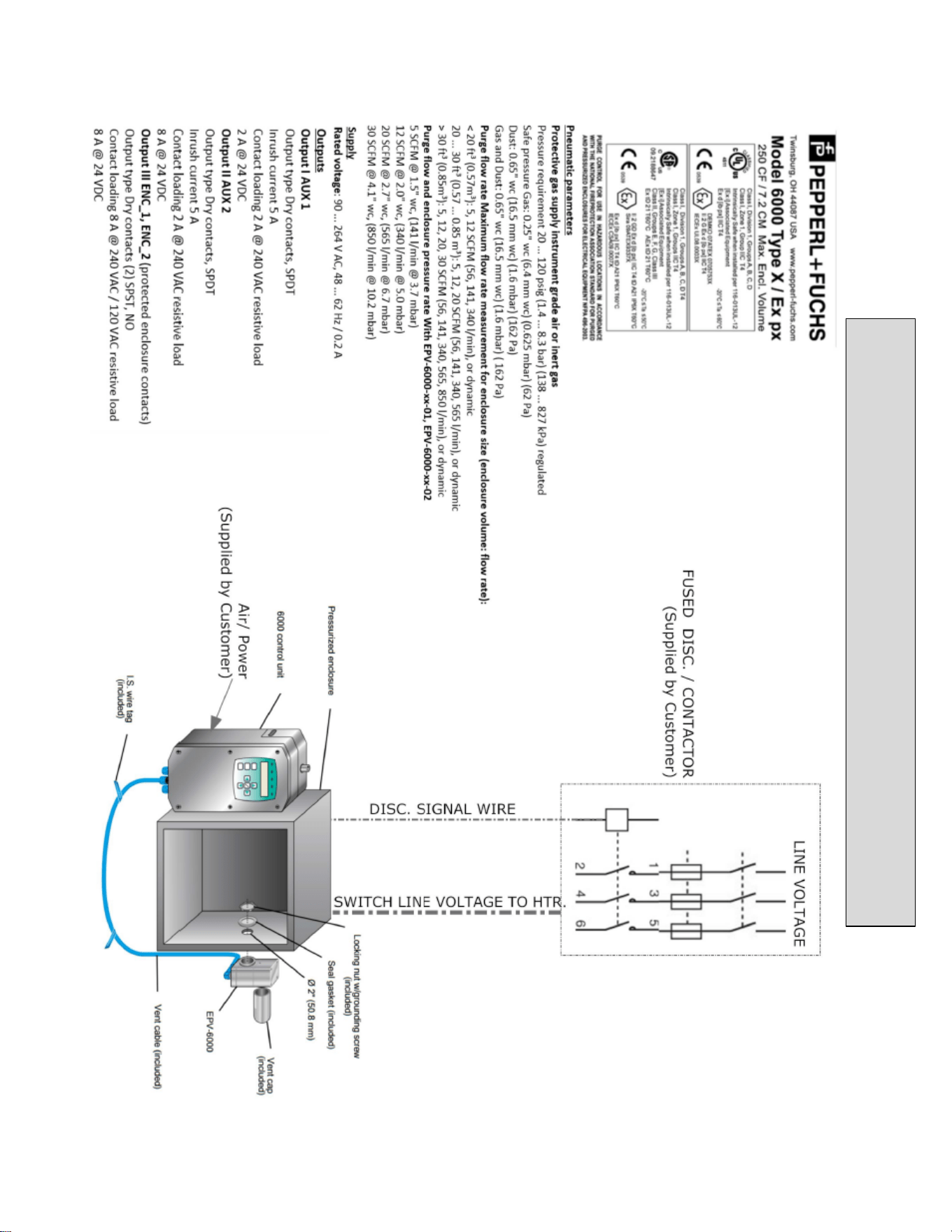
AVAILABLE WITH EP
-
6000 UNIT

56
System Maintenance
Regular Maintenance
Drain the Protection System Filter (if utilized) frequently and clean system with non-solvent cleaning agents only.
Long Term Maintenance
Calibrate the enclosure pressure indicator to 0 inches by venting the purge pressure reference port and the protected
enclosure to atmosphere and adjusting the calibration screw in the lower center portion of the indicator’s face.
Fully open the enclosure pressure control valve, to blow out any deposits around the tip of the valve and to ensure that
the enclosure protection vent is operating properly, then carefully readjust system according to the set-up procedure
and operating sequence on pages 50. Replace or tighten stem packing nut as required to prohibit stem packing leakage.
Carefully disassemble the enclosure protection vent by loosening the two bottom hex nuts that hold the unit together.
(DO NOT REMOVE CAP NUTS ON TOP OF VENT BODY)
Carefully clean the flapper valve and vent body seats with warm soap and water, being careful not to extend the vent
valve beyond its normal opening point, and being careful not to exert any stress on the valve hinge.
Examine the entire Protection System and the protected enclosure(s), and replace any defective parts curing routine
shutdown of the protected enclosure(s). Parts are available from Pepperl+Fuchs on immediate notice as required.
Maintenance Schedule
Date
Work Performed
Performed By
57
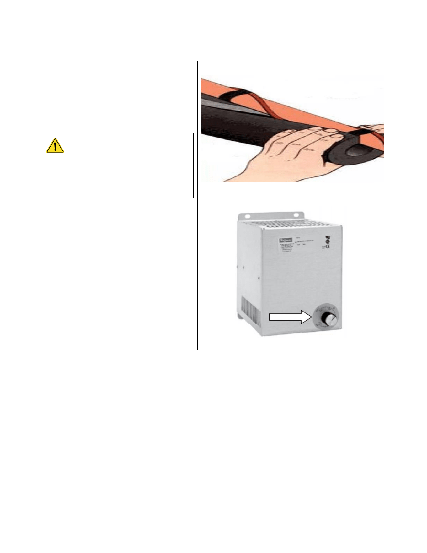
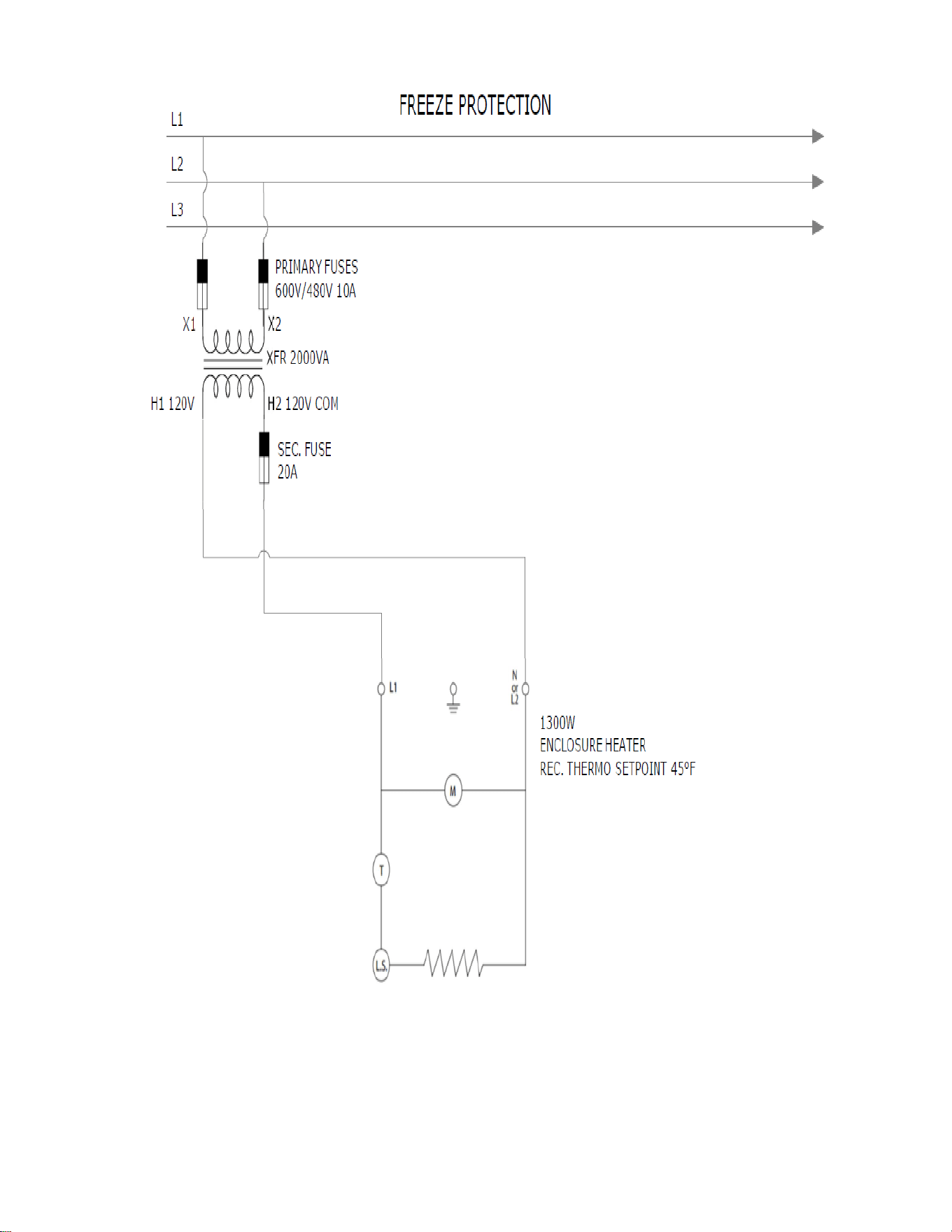
Optional Enclosure Heater
1) Attach heat tape and foam insulation to all
lengths of inlet and outlet water piping that are
exposed to freezing temperature. We recommend
a rating of -30 degrees F at 10 miles per hour
wind. Connect the heat tape to an independent
source of electrical power.
CAUTION
Failure to attached heat tape and
insulation to exposed inlet and
outlet pipes will void the warranty.
2) Set the thermostat on the enclosure heater,
located at the upper left corner in the enclosure,
to 40 – 70 degrees F.
Note: Heater fan continuously operates to
recirculate air in the enclosure. The heater coil will
activate based on thermostat set point.
Note: Power must be applied to the water heater for the freeze protection
system to operate. If power is not applied ensure the system is completely
drained. Neglecting to do so will damage the heater and void the warranty.
58
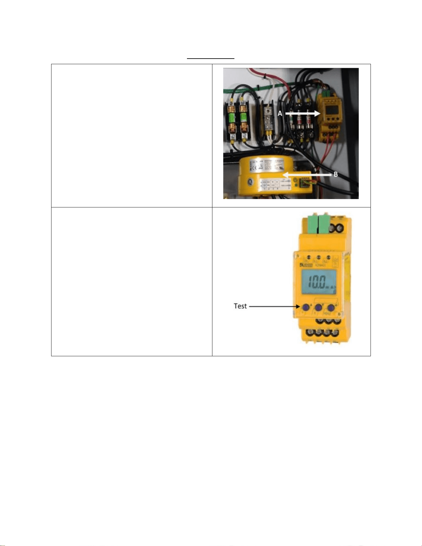
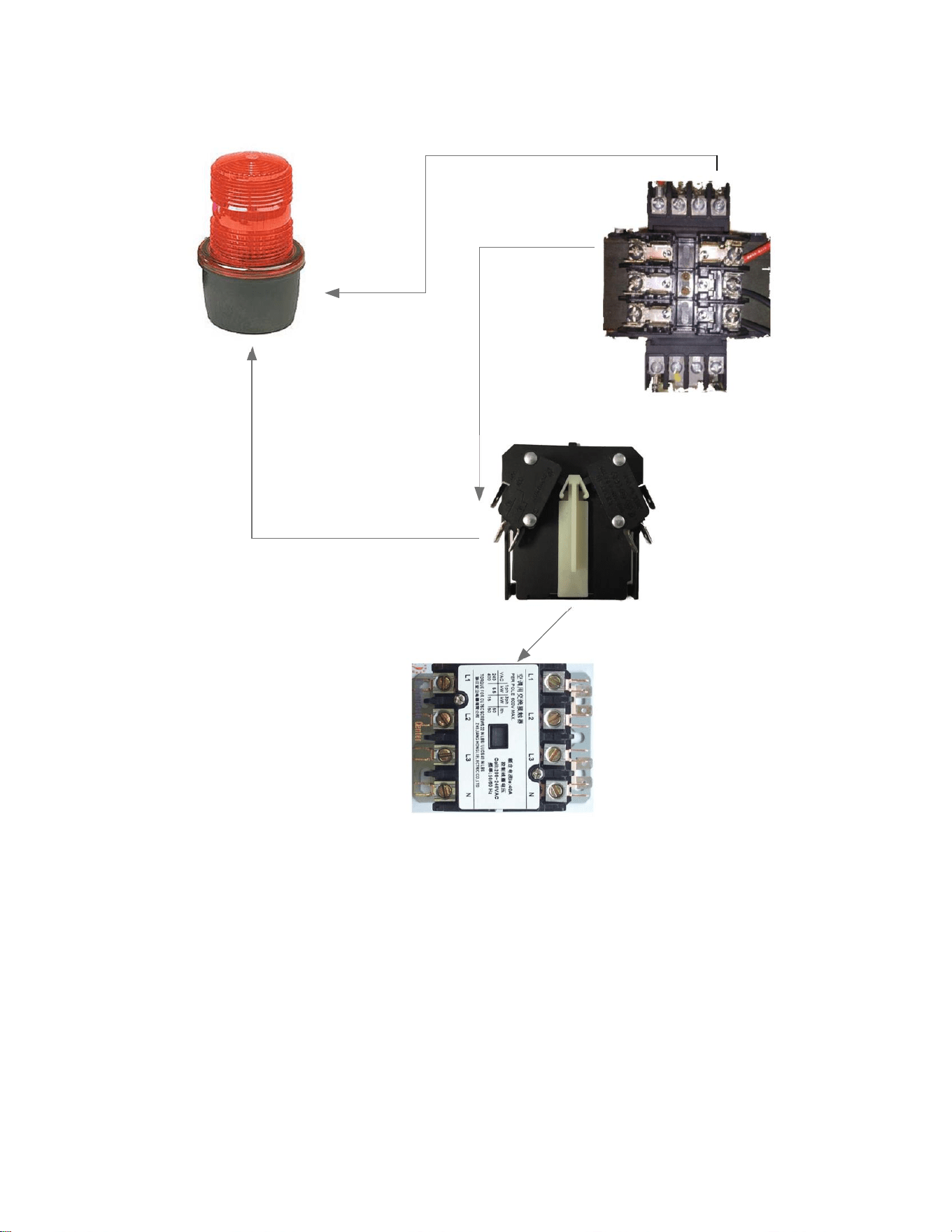
Optional GFCI
The optional GFCI consist of (A) Control Module
and (B) Current Transformer. This control module
has a LCD display indicating real-time
measurements. The GFCI module is preset from
factory to trip at 3.0 A.
Test and reset functions are carried out
automatically every 24 hours. To manual test the
GFCI, press the test button for a minimum of 1.5
seconds. To reset a tripped GFCI, cycle the power of
the unit. If equipped with a disconnect handle, turn
the handle to the “OFF” position then back to
“ON”.

59
DISCONNECT SWITCH MODEL
60 A
100 A
200 A
Operating Voltage
600 V
600 V
600 V
Max Horsepower Rating:
120 VAC 1-Phase
3
-
-
220/240 VAC 1-Phase
10
10
10
220/240 VAC 3-Phase
20
30
75
440/480 VAC 3-Phase
40
75
150
600 VAC 3=Phase
50
100
200
Short circuit rating with fuses
100
200
200
Branch circuit fuse type
J
J
J
Max fuse rating (A)
60
100
200
Disconnect Handle
NEMA Type: 4, 4X
Color: Red/Yellow
Optional NON-FUSIBLE Disconnect Switch

60
208 v
50/150
25/78.5
240 v
60/154
30/80
480 v
125/156
60/77
600 v
130/144
75/77
DC 125 V (2 pole in series)
15/112
7.5/58
DC 250 V (3 pole in series)
40/140
20/38
Short circuit rating with fuses
200
200
Branch circuit fuse type
J
J
Max fuse rating (A)
200
100
DISCONNECT SWITCH MODEL
200 AMP
100 AMP
RATING (A)
200 A
100 A
600 V
600 V
Max horsepower rating/ Max motor
FLA current phase Three
DISCONNECT HANDLE
NEMA TYPE: 4,4x
COLOR: RED/YELLOW
Optional FUSIBLE Disconnect Switch
61
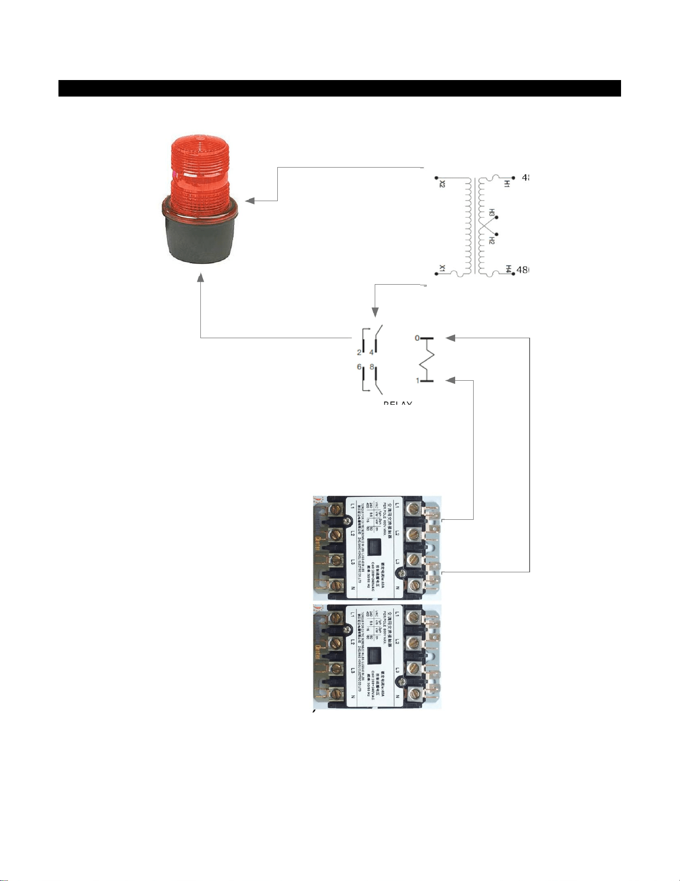
WIRING SCHEMATICS
COIL A1
COIL A2
RELAY
120V COM
120V
480V L1
480V L2
AP SIREN BEACON ONLY
WIRING DIAGRAM
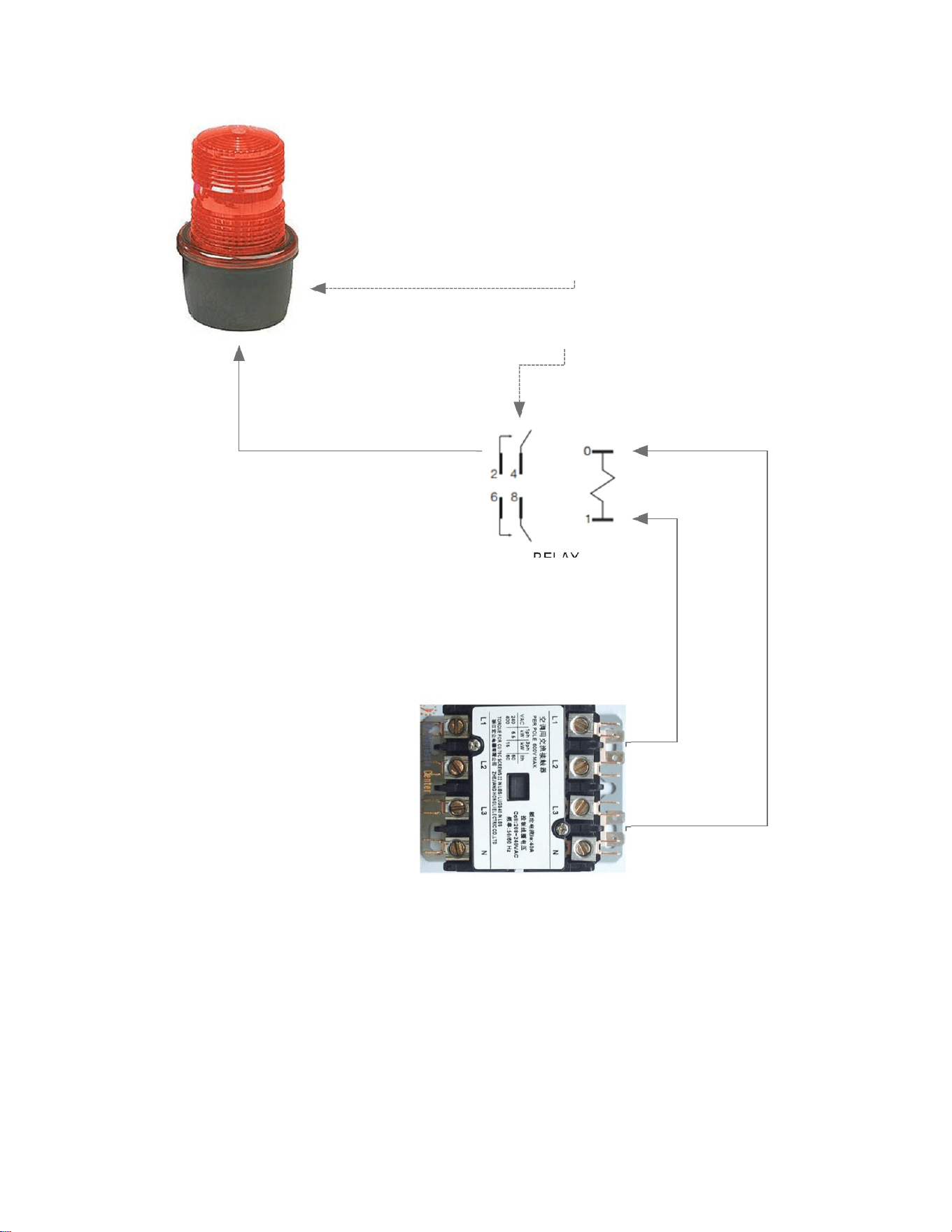
62
COIL A1
COIL A2
RELAY
120V COM
120V
AP SIREN BEACON ONLY
WIRING DIAGRAM
TOP CONTACTOR
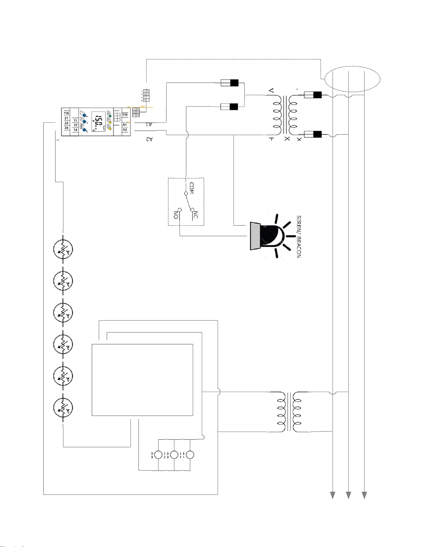
63
L1
L2
L3
X1 X2
H1 120V H2 120V COM
X1 X2
H1 24VAC H2 24VAC RTN
ECO ECO ECO ECO ECO ECO
C1
C2
C3
P16
P17
12
11
GFCI
FUSE
SB
FUSE
COM
NO
NC
AUX CONTACT 1
CT RING
PHD MCB
C
O
N
T
A
C
T
O
R
C
O
I
L
S
SIREN/ BEACON
A
2
A
1
PHD XFR
XFR 2
GFCI SIREN BEACON DIAG
64
COIL A1
COIL A2
AP SIREN BEACON ONLY
WIRING DIAGRAM
TOP CONTACTOR
(H2) 120V COM
TO COM
TO NO
ATTACHES TO SIDE OF
CONTACTOR
(H1) 120V
X1 208/480/600 L1
X2 208/480/600 L2
65
66
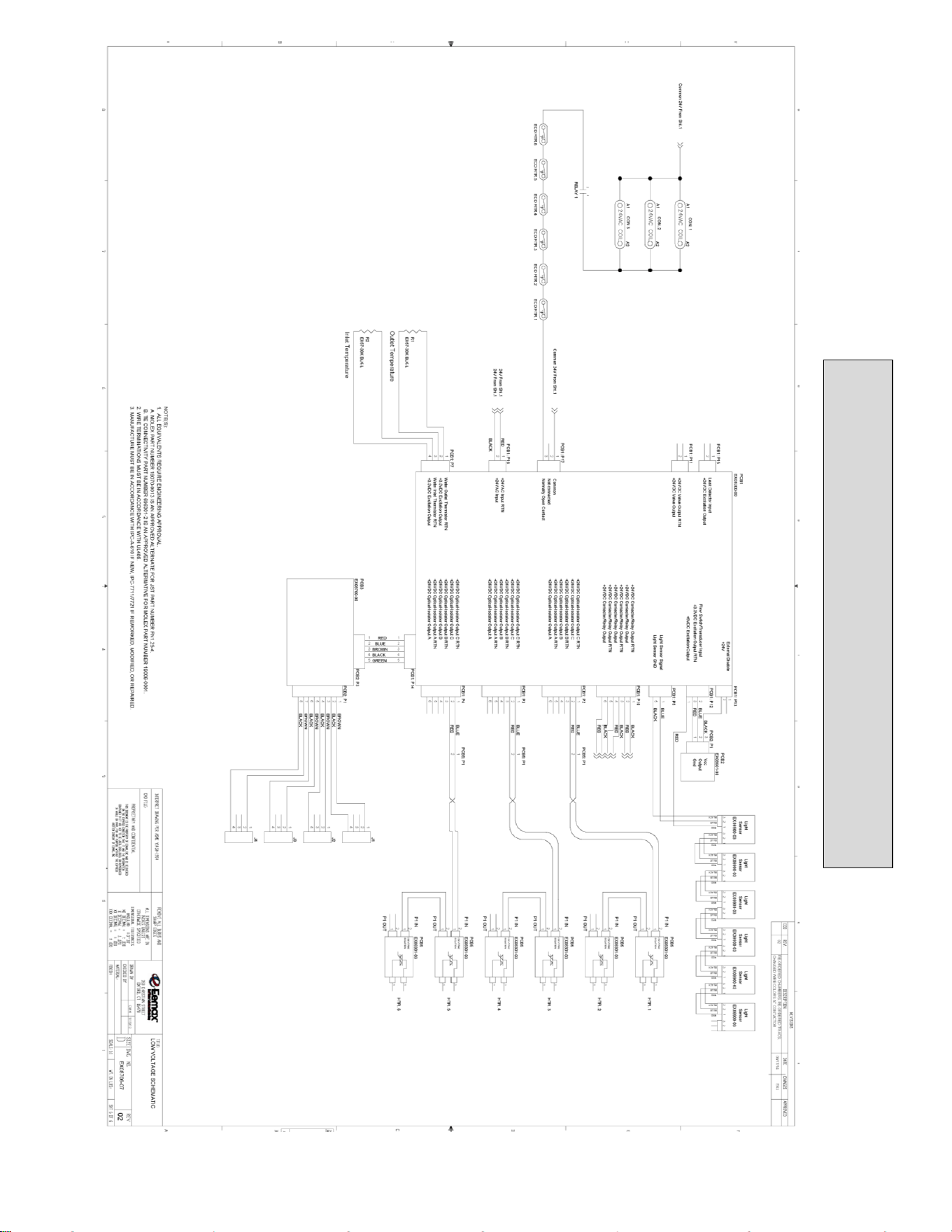
LOW VOLTAGE SCHEMATIC
67
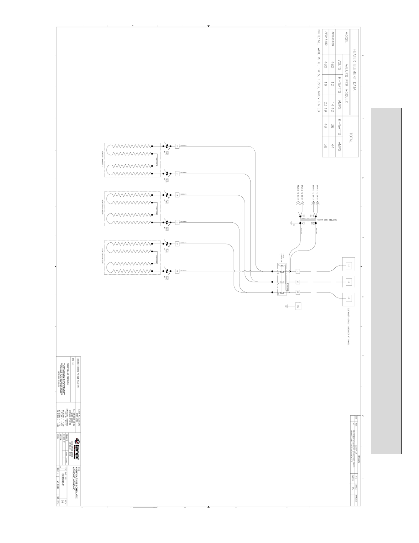
AP036480/AP048480 WIRING SCHEMATIC
68
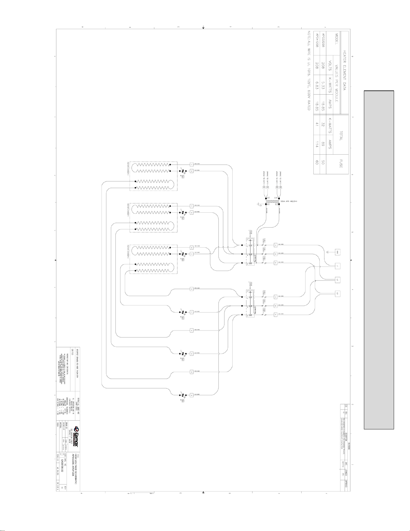
AP032208/AP041208 WIRING SCHEMATIC
69
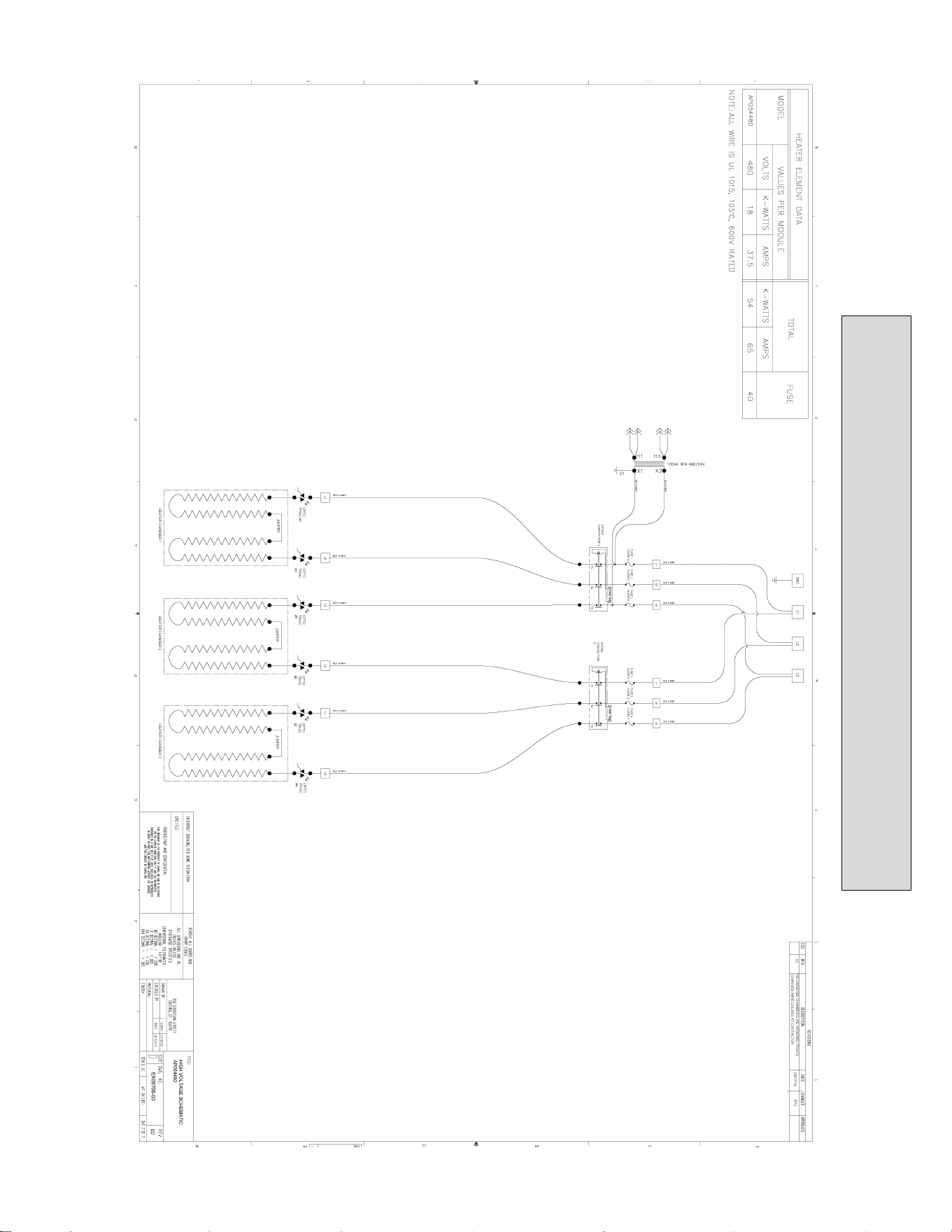
AP054480 WIRING SCHEMATIC
70
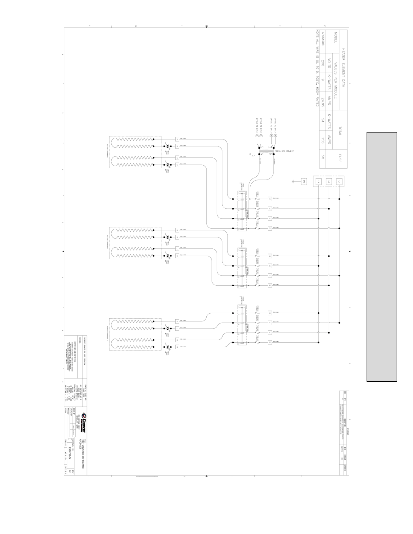
AP054208 WIRING SCHEMATIC
71
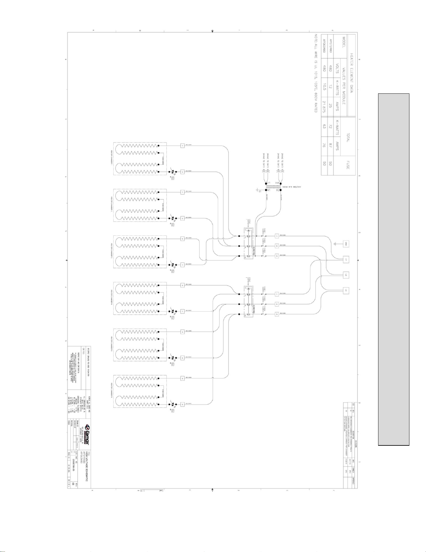
AP072480/AP063480 WIRING SCHEMATIC
72
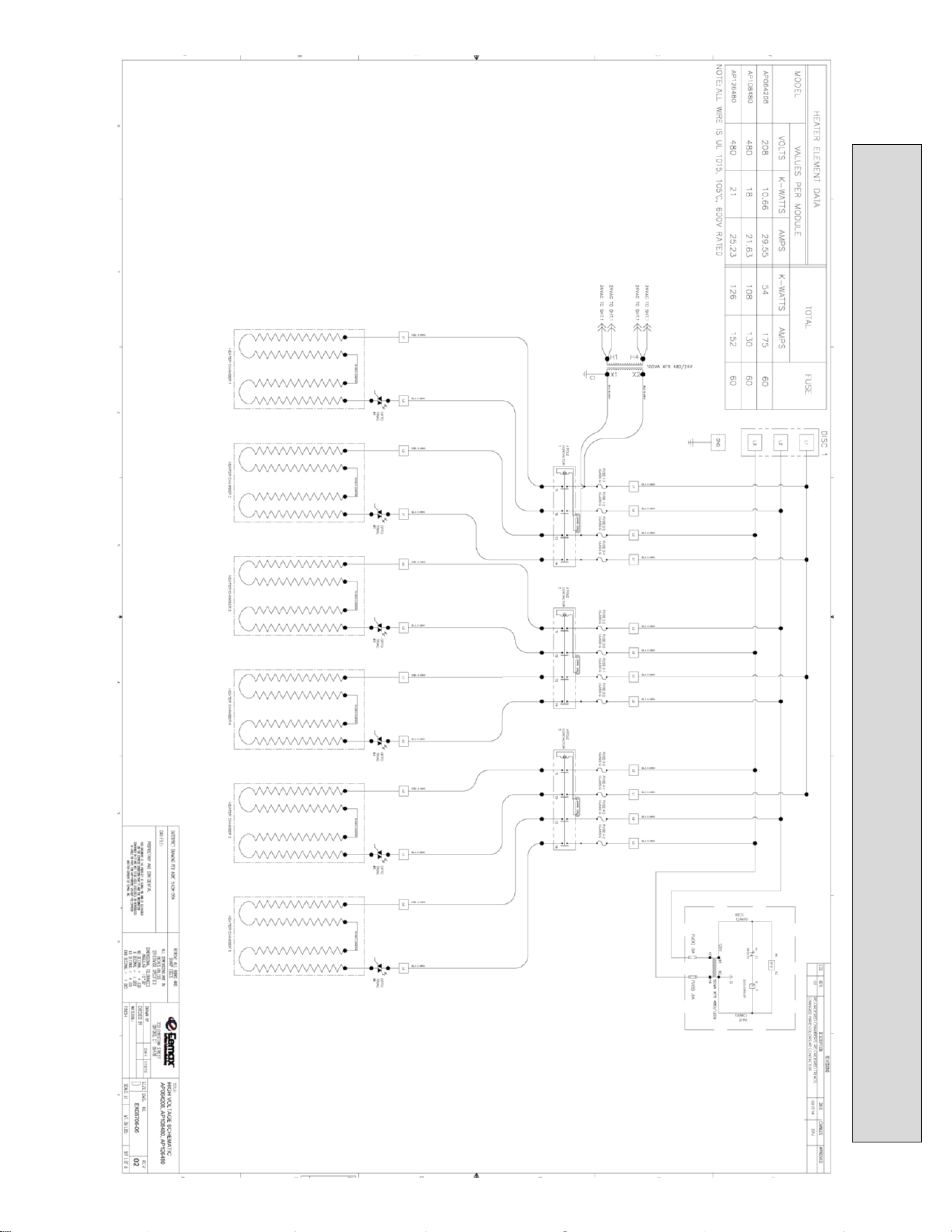
AP064208/AP096480/AP108480 WIRING SCHEMATIC

EX07200-15 REV 9
73
USA AND CANADA:
Eemax Inc.
400 Captain Neville Drive, Waterbury, CT 06705
Toll Free: 1-800-543-6163, or 203-267-7890 Fax: 203-267-7975
Eemax.Support@eemax.com

