TEC_TM_043 | REV. F | EN
03/2/2023
Page 1 of 40
TBR
|
TDR SERIES
INSTALLATION MANUAL
TRUE MANUFACTURING CO., INC.
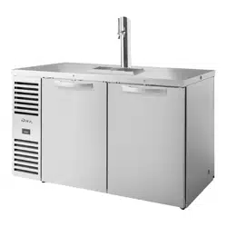
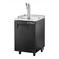
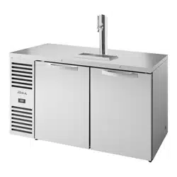
TDR48-RISZ1-L-B-SG
TBR32-RISZ1-L-B-S-1
INSTALLATION MANUAL
TBR
|
TDR SERIES
Original Instructions
TRUE MANUFACTURING CO., INC.
2001 East Terra Lane • O’Fallon, Missouri 63366-4434
(636) 240-2400 • FAX: (636)-272-2408
International FAX: (636)-272-7546 • (800)-325-6152
Parts Department: (800)-424-TRUE (424-8783)
Parts Department FAX: (636)-272-9471
North America – Canada and Caribbean
Warranty Phone: +1 855-878-9277
Warranty Fax: +1 636-980-8510
Warranty Email: WarrantyInquiries@TrueMfg.com
Technical Phone: +1 855-372-1368
Technical Email: Service@TrueMfg.com
7:00am–6:00pm CST Monday–Friday,
8:00am–12:00pm Saturday
UK, Ireland, Middle East, Africa
& India
Phone: +44 (0) 800-783-2049
Service-EMEA@TrueMfg.com
8:30am–5:00pm M–F
European Union & Commonwealth of
Independent States
Phone: +49 (0) 7622-6883-0
Service-EMEA@TrueMfg.com
8:00am–5:00pm M–F
Australia
Phone: +61 2-9618-9999
Service-Aus@TrueMfg.com
8:30am–5:00pm M–F
Mexico
Phone: +52 555-804-6343/44
Service-MexicoCity@TrueMfg.com
9:00am–5:30pm M–F
Latin America
Phone: +52 555-804-6343/44
ServiceLatAm@TrueMfg.com
9:00am–5:30pm M–F
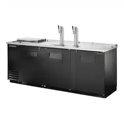
TBR72-RISZ1-L-S-GGG
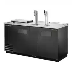
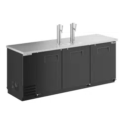
TBR72-RISZ1-L-B-111-1

TBR
|
TDR SERIES www.truemfg.com
TEC_TM_043 | REV. F | EN03/2/2023 Page 2 of 40 P#803294
THANK YOU
FOR YOUR PURCHASE
Congratulations!
You have just purchased the finest commercial refrigerator available. You can expect many
years of trouble-free operation.
Table of Contents
Safety Information
Safety Precautions & Proper Disposal ..........3
Prior to Installation
Ownership .............................................................4
Cabinet Location .................................................4
Notice to Customer ............................................4
Wire Gauge Chart ................................................4
Installation
Uncrating ................................................................5
Cabinet Location .................................................6
Leveling Leg, 6" Leveling Leg &
Castor Installation ........................................... 6
Leveling & Sealing the Cabinet
to the Floor ......................................................... 7
Electrical Installation & Safety ........................8
Cabinet Setup
Shelf Installation .................................................. 9
Draft Tower Installation ...................................10
Draft Spill Tray ....................................................11
Air Distributor Manifold &
Distributor Cover ...........................................12
CO2 & Keg Connections ...................................12
Beer Drain Bottle & Hanger ...........................13
Access Ports .........................................................13
Overlay Panel Specifications .........................15
Overlay Panel Installation...............................19
Cabinet Operation
Startup, Temperature Control &
Light Switch Location ..................................21
General Sequence of Operation ..................22
Draft Beer Storage, Handling &
Operation .........................................................23
Draft Beer Problems &
Troubleshooting ............................................24
Changing CO₂ Gas Cylinder ...........................25
Maintenance, Care, and Cleaning
Draft Tower Cleaning .......................................26
Condenser Coil Cleaning ................................27
Stainless Steel Care & Cleaning ....................29
Cabinet Adjustments, Servicing &
Component Replacement
Servicing & Replacing Components...........30
Reverse Door Swing .........................................30
Slide Door Removal ..........................................32
Slide Door Operation .......................................34
Gasket Replacement ........................................35
Swing Door Lock & Cam Replacement......36
Warranty
Warranty ...............................................................37
TBR
|
TDR SERIES
TEC_TM_043 | REV. F | EN
03/2/2023
Page 3 of 40
www.truemfg.com
How to Maintain Your True Refrigerator to Receive the Most Efficient and Successful Operation
You have selected one of the finest commercial refrigeration units made. It is manufactured under strict quality controls with only the best
quality materials available. Your TRUE cooler, when properly maintained, will give you many years of trouble-free service.
WARNING – Use this appliance for its intended purpose as described in this Installation Manual.
• Take care during operation, maintenance or repairs to avoid
cuts or pinching from any part/component of the cabinet.
• Units may pose a tipping hazard while uncrating, during
installation, or when moving the unit.
• Ensure the unit is properly installed and located in accordance
with the Installation Instructions before use.
• This appliance is not to be used, cleaned or maintained by
persons (including children) with reduced physical, sensory or
mental capabilities or lack of experience and knowledge, unless
they have been given supervision or instruction.
• DO NOT allow children to play with the appliance or climb,
stand, or hang on the unit's shelves to prevent damage to the
refrigerator and personal injury.
• DO NOT touch the cold surfaces in the freezer compartment
when hands are damp or wet. Skin may stick to these extremely
cold surfaces.
• Unplug the refrigerator before cleaning and making repairs.
• Setting temperature controls to the 0 position or powering
off an electronic control may not remove power from all
components (e.g., light circuits, perimeter heaters, and
evaporator fans).
• DO NOT store or use gasoline, or other flammable vapors and
liquids, in the vicinity of this or any other appliance.
• DO NOT store explosive substances such as aerosol cans with a
flammable propellant in this appliance.
• Keep fingers out of the “pinch point” areas; clearances between
the doors and cabinet are necessarily small; be careful closing
doors when children are in the area.
• DO NOT use electrical appliances inside the food storage
compartments of the units unless the appliances are of the
type recommended by the manufacturer.
NOTE: All servicing must be performed by a qualified
technician.
See the serial label inside the cabinet for the units refrigeration type. For Hydrocarbon Refrigeration (R290 only), see below:
DANGER – Risk of fire or explosion. Flammable refrigerant used. DO NOT use mechanical devices to defrost
refrigerator. DO NOT puncture refrigerant tubing; follow handling instructions carefully. To be repaired only by trained
service personnel.
DANGER – Risk of fire or explosion (flammable refrigerant used), consult repair manual/owner’s guide before
attempting to service this product. All safety precautions must be followed. Dispose of properly in accordance with
local and federal regulations. Follow all safety precautions.
CAUTION – Keep all ventilation openings clear of obstruction in the appliance enclosure or in the structure housing
the appliance.
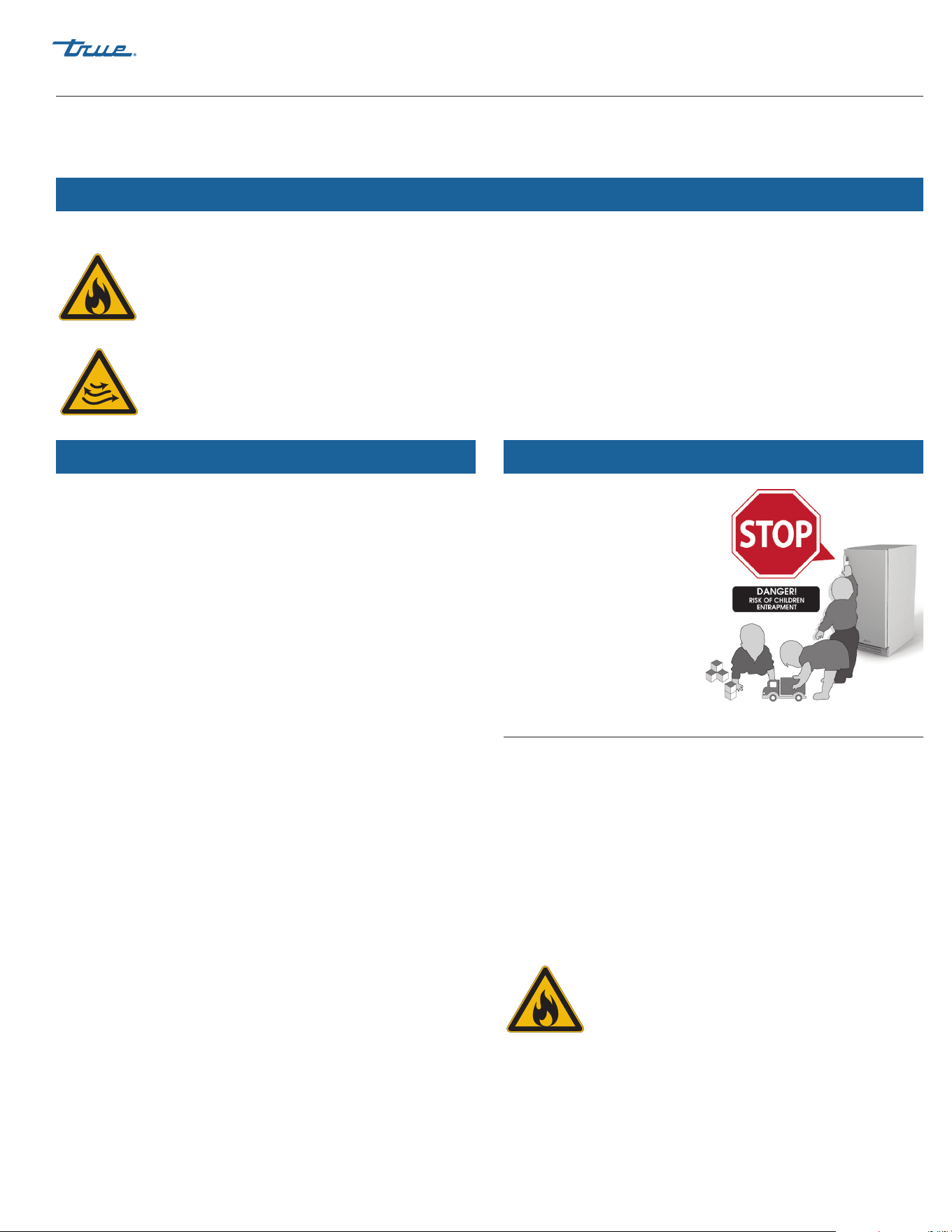
DANGER!
RISK OF CHILD
ENTRAPMENT
Proper Disposal of the Cabinet
Child entrapment and suffocation are not problems of the past.
Junked or abandoned refrigerators are still dangerous, even if
they will sit for “just a few days.” If you are getting rid of your old
refrigerator, please follow the instructions below to help prevent
accidents.
Before throwing away your old refrigerator or freezer:
• Take off the doors.
• Leave the shelves in place so that children may not easily
climb inside.
DANGER – Risk of fire or explosion. Flammable insulation and/
or refrigerant used. Dispose of all in accordance
with local and federal regulations. Follow all safety
precautions.
Cabinet Disposal Warning
Refrigerant Safety & Warning Information
Basic Safety & Warning Precautions
TBR
|
TDR SERIES www.truemfg.com
TEC_TM_043 | REV. F | EN03/2/2023 Page 4 of 40 P#803294
CLEARANCES
TOP SIDES BACK
TBR/TDR 0" (0 mm) 0" (0 mm) 0" (0 mm)
WARNING – Warranty is void if ventilation is insufficient.
Prior to Installation
Ownership
To ensure that your unit works properly from the first day, it must
be installed properly. We highly recommend a trained refrigeration
mechanic and electrician install your TRUE equipment. The cost of
a professional installation is money well spent.
Before you start to install your TRUE unit, carefully inspect it for
freight damage. If damage is discovered, immediately file a claim
with the delivery freight carrier.
TRUE is not responsible for damage incurred during shipment.
Cabinet Location
• Appliance tested for IEC to ISO Climate Class 5 [104°F (40°C)
temperature, 40% relative humidity].
• For proper operation, ambient temperatures shall not be less
than 60°F (15.5°C) and no greater than 104°F (40°C).
• Appliance is not suitable for outdoor use.
• Appliance is not suitable for an area where a pressure washer or
hose may be used.
• Ensure the location will provide adequate clearances and
sufficient airflow for the cabinet.
• Ensure the power supply for the cabinet matches the cabinet
specification sheet or cabinet data plate and is within the
rated voltage (+/-5%). Also, that the amp rating of the circuit is
correct and that it is properly grounded.
• The cabinet should always be plugged into its own individual
dedicated electrical circuit. The use of adapter plugs and
extension cords is prohibited.
Notice to Customer
Loss or spoilage of products in your
refrigerator/freezer is not covered by
warranty. In addition to following
recommended installation procedures, you
must run the refrigerator/freezer for 24 hours
prior to usage to verify its proper operation.
115
Volts Distance In Feet To Center of Load
AMPS 20 30 40 50 60 70 80 90 100 120 140 160
2 14 14 14 14 14 14 14 14 14 14 14 14
3 14 14 14 14 14 14 14 14 14 14 14 12
4 14 14 14 14 14 14 14 14 14 12 12 12
5 14 14 14 14 14 14 14 12 12 12 10 10
6 14 14 14 14 14 14 12 12 12 10 10 10
7 14 14 14 14 14 12 12 12 10 10 10 8
8 14 14 14 14 12 12 12 10 10 10 8 8
9 14 14 14 12 12 12 10 10 10 8 8 8
10 14 14 14 12 12 10 10 10 10 8 8 8
12 14 14 12 12 10 10 10 8 8 8 8 6
14 14 14 12 10 10 10 8 8 8 6 6 6
16 14 12 12 10 10 8 8 8 8 6 6 6
18 14 12 10 10 8 8 8 8 8 8 8 5
20 14 12 10 10 8 8 8 6 6 6 5 5
25 12 10 10 8 8 6 6 6 6 5 4 4
30 12 10 8 8 6 6 6 6 5 4 4 3
35 10 10 8 6 6 6 5 5 4 4 3 2
40 10 8 8 6 6 5 5 4 4 3 2 2
45 10 8 6 6 6 5 4 4 3 3 2 1
50 10 8 6 6 5 4 4 3 3 2 1 1
230
Volts Distance In Feet To Center of Load
AMPS 20 30 40 50 60 70 80 90 100 120 140 160
5 14 14 14 14 14 14 14 14 14 14 14 14
6 14 14 14 14 14 14 14 14 14 14 14 12
7 14 14 14 14 14 14 14 14 14 14 12 12
8 14 14 14 14 14 14 14 14 14 12 12 12
9 14 14 14 14 14 14 14 14 12 12 12 10
10 14 14 14 14 14 14 14 12 12 12 10 10
12 14 14 14 14 14 14 12 12 12 10 10 10
14 14 14 14 14 14 12 12 12 10 10 10 8
16 14 14 14 14 12 12 12 10 10 10 8 8
18 14 14 14 12 12 12 10 10 10 8 8 8
20 14 14 14 12 10 10 10 10 10 8 8 8
25 14 14 12 12 10 10 10 10 8 8 6 6
30 14 12 12 10 10 10 8 8 8 6 6 6
35 14 12 10 10 10 8 8 8 8 6 6 5
40 14 12 10 10 8 8 8 6 6 6 5 5
50 12 10 10 8 6 6 6 6 6 5 4 4
60 12 10 8 6 6 6 6 6 5 4 4 3
70 10 10 8 6 6 6 5 5 4 4 2 2
80 10 8 8 6 6 5 5 4 4 3 2 2
90 10 8 6 6 5 5 4 4 3 3 1 1
100 10 8 6 6 5 4 4 3 3 2 1 1
Wire Gauge Chart
TBR
|
TDR SERIES
TEC_TM_043 | REV. F | EN
03/2/2023
Page 5 of 40
www.truemfg.com
Installation
Uncrating
Tools Required
• Adjustable wrench
• Phillips screwdriver
• Level
The following procedure is recommended for uncrating the unit:
Procedure
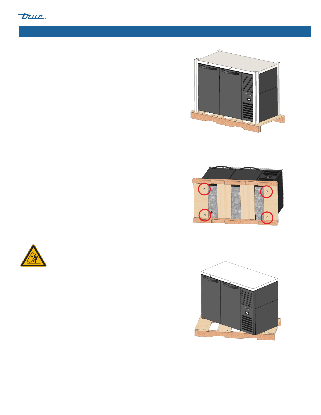
1. Remove the outer packaging (cardboard and bubbles or
styrofoam corners and clear plastic). See fig. 1. Inspect for
concealed damage. Again, immediately file a claim with the
freight carrier if there is damage.
NOTE: Move the unit as close as possible to the final
location before removing the wooden skid.
2. With an adjustable wrench, remove all shipping bolts securing
the wood skid to the bottom of the cabinet. See fig. 2.
NOTE: Some models may require removing the front and/or
rear grill to access the shipping bolts.
3. If leveling legs or castors will not be used, remove the
cabinet from the wood skid and set the skid aside.
NOTE: DO NOT lift the cabinet by the countertops, doors,
drawers, or grills.
If leveling legs or castors will be used, rotate the cabinet on
the skid (see fig. 3) and see the installation instructions on the
next page.
NOTE: Remember to leave cabinet upright for 24 hours before
plugging into a power source. Keys for cabinet with door locks
are located in the warranty packet.
WARNING – Units may pose a tipping hazard
while uncrating, during installation, or when
moving the unit.
Fig. 1. Remove the exterior packaging.
Fig. 2. Shipping bolt locations.
Fig. 3. When lifting unit, do not use countertops, doors/drawers, or grills
as a lifting point.
TBR
|
TDR SERIES www.truemfg.com
TEC_TM_043 | REV. F | EN03/2/2023 Page 6 of 40 P#803294
Installation (cont.)
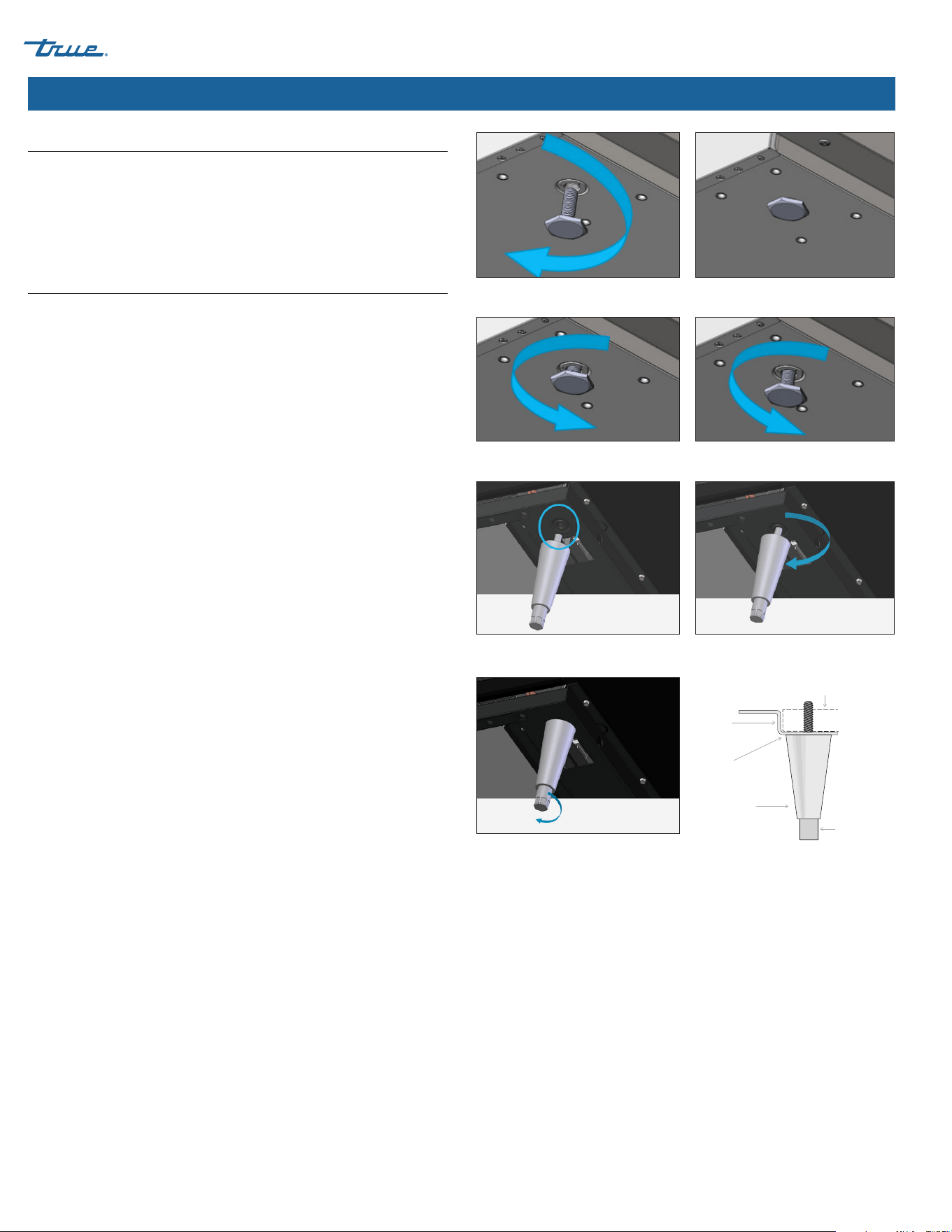
Fig. 1. Turn the leveling legs clockwise to lower the unit.
Cabinet Location
1. Ensure that the drain hose or hoses are positioned in the pan.
2. Free the plug and cord from inside the lower rear of the cooler
(DO NOT plug in).
3. Place the unit close enough to the electrical supply so that the
extension cords are never used.
Leveling Leg, 6" Leveling Leg, or Castor Installation
Leveling legs are provided to assist with leveling the cabinet.
Adjustable legs will provide 6" (152 mm) of clearance under the
cabinet. Castors provide cabinet mobility.
NOTE: If the cabinet has a center leveling screw, castor, or leg,
make sure it is adjusted properly so it makes full contact with
the floor after the cabinet has been leveled.
Required Tools
Required tools include (but may not be limited to) the following:
Adjustable Wrench
Procedure: Leveling Legs
With access to the bottom of the cabinet, thread the leveling legs
into the holes used to secure the cabinet to the skid. See figs. 1
and 2.
Procedure: 6" (152 mm) Leveling Legs
1. Access the bottom of the cabinet and thread the leveling legs
into the rail. See figs. 3 and 4.
2. Verify that the cabinet is level.
3. If the cabinet is not level, gently lift and support the low end
of the cabinet. With an adjustable wrench, screw the bottom
stem of the leveling leg in or out to level and support the
cabinet. See fig. 5.
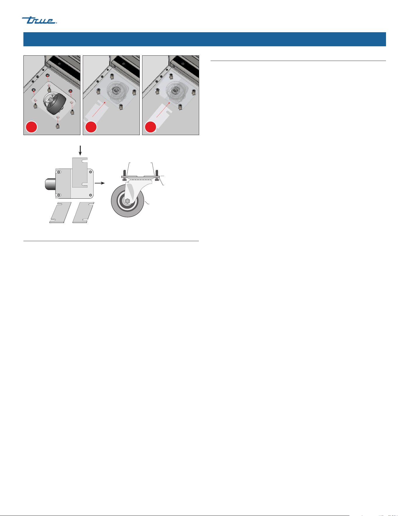
Procedure: Castors
1. Locate the castor anchor points on the underside of the
cabinet.
2. With an adjustable wrench and the provided hardware, install
the plate castors.
NOTE: DO NOT overtighten the bolts.
3. Verify the level of the cabinet. If the cabinet is not level, gently
lift and support the low end of the cabinet and add castor
shims.
a. Loosen the castor bolts to create space between the
mounting plate and the bottom of the cabinet. See fig. 6a.
b. Position the castor shims and tighten the castor bolts. See
figs. 6b and 6c.
c. Lower the cabinet and verify it is level. Repeat the process
until the cabinet is level.
NOTE: Install shims in pairs and ensure the shims contact
the castor mounting bolts.
Fig. 2. Turn the leveling legs counterclockwise to raise the unit.
Fig. 5. Turn the bottom stem to level the
cabinet.
Fig. 3. Locate the threaded hole in the
rail.
Fig. 4. Screw in the leveling legs.
Lower Rail Assembly
Seismic
Leg
Snug Fit
Here
Rail End
Bottom Stem
TBR
|
TDR SERIES
TEC_TM_043 | REV. F | EN
03/2/2023
Page 7 of 40
www.truemfg.com
Installation (cont.)
Leveling
Proper leveling of your TRUE cooler is critical to operating success
(for non-mobile models). Leveling impacts effective condensate
removal and door operation.
Procedure
Level the unit front-to-back and side-to-side.
1. Position the level on the inside floor of the unit near the doors
(the level should be parallel to cabinet front). Level the cabinet.
2. Position the level at the inside rear of cabinet (again, the level
should be placed parallel to cabinet back). Level the cabinet.
3. Perform procedures similar to steps 1 and 2 by placing the
level on inside floor (left and right side, parallel to the depth of
the cooler). Level the cabinet.
NOTE: If the cabinet has a center leveling screw, castor, or leg,
make sure it is adjusted properly so it makes full contact with
the floor after the cabinet has been leveled.
Sealing the Cabinet to the Floor
Asphalt floors are susceptible to chemical attack. A layer of tape
may be placed on the floor prior to applying the sealant to protect
the floor.
Procedure
1. Position the cabinet, allowing 3" (73 mm) between the wall
and the rear of the cabinet to ensure proper ventilation.
2. Level the cabinet. The cabinet should be level side-to-side
and front-to-back. To check that the cabinet is level, place a
carpenter's level on the interior cabinet floor in four places:
a. Position the level on the inside floor of the cabinet, near
the doors (the level should be placed parallel to the cabinet
front). Level the cabinet.
b. Position the level at the inside rear of the cabinet (the level
should be placed parallel to the cabinet back). Level the
cabinet.
c. Perform procedures similar to a and b by placing the level
on the left and right inside floor (level should be parallel to
the cabinet sides). Level the cabinet.
3. Draw an outline of the cooler base on the floor.
4. Raise and block the front side of the cabinet.
5. Apply a bead of NSF-approved sealant (see list below) to the
floor, 1/2" (13 mm) inside the front part of the outline drawn in
step 4. The bead of sealant must be heavy enough to seal the
entire cabinet surface when the cabinet is lowered on top of
the sealant.
6. Raise and block the rear of the cabinet.
7. Apply sealant to the floor on the other three sides, as outlined
in step 5.
8. Examine the the cabinet to ensure that it is sealed to the floor
around the entire perimeter.
NSF-Approved Sealants
• 3M #ECU800 Caulk
• 3M #ECU2185 Caulk
• 3M #ECU1055 Bead
• 3M #ECU1202 Bead
• Armstrong Cork – Rubber Caulk
• Products Research Co. #5000 Rubber Caulk
• G.E. Silicone Sealer
• Dow Corning Silicone Sealer
A B C
Fig. 6. Install castor shims in pairs.
Snug Fit
Here
Castor
Mounting
Plate
Castor
Leveling Shims
Leveling Shims
Side View
Left
Shim in
Position
Top View
TBR
|
TDR SERIES www.truemfg.com
TEC_TM_043 | REV. F | EN03/2/2023 Page 8 of 40 P#803294
Installation (cont.)
How to Connect Electricity
• The power cord from this appliance is equipped with a
grounding plug which minimizes the possibility of electric
shock hazard.
• The wall outlet and circuit should be checked by a licensed
electrician to make sure the outlet is properly grounded.
• If the outlet is a standard 2-prong outlet, it is your personal
responsibility and obligation to have it replaced with the
properly grounded wall outlet.
• DO NOT, under any circumstances, cut or remove the ground
prong from the power cord. For personal safety, this appliance
must be properly grounded.
• Before your new unit is connected to a power supply, check
the incoming voltage with a voltmeter. If the recorded voltage
is less than the rated voltage for operation (+/-5%) and amp
rating, correct immediately. Refer to cabinet data plate for this
voltage requirement.
• The refrigerator/freezer should always be plugged into a
dedicated electrical circuit. This provides the best performance
and prevents building wiring circuits from being overloaded,
which could cause a fire hazard from overheated wires.
• Never unplug your refrigerator/freezer by pulling on the power
cord. Always grip plug firmly and pull straight out from the
outlet.
• When moving the refrigerator/freezer, for any reason, be careful
not to roll over or damage the power cord.
• Repair or replace immediately all power cords that have
become frayed or otherwise damaged. DO NOT use a power
cord that shows cracks or abrasion damage along its length or
at either end.
• If the supply power cord is damaged, it should be replaced with
original equipment manufacturer (OEM) components. To avoid
hazard this should be done by a licensed service provider.
Cabinet Wiring Diagram
The cabinet's wiring diagram is in the exterior servicing
compartment space of the cabinet.
A copy of the wiring diagram may also be obtained at
www. truemfg.com/support/serial-number-lookup
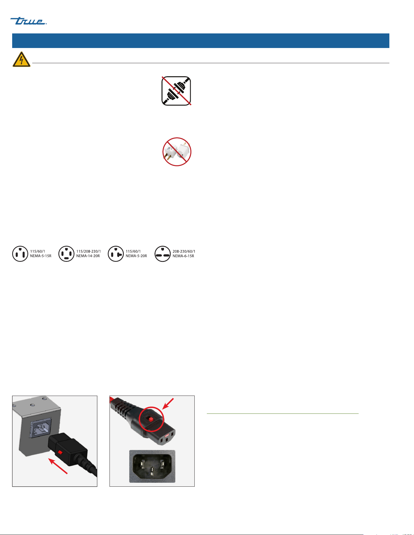
Fig. 1. Fully insert the power cord into
the receptacle.
Fig. 2. Push the red button to remove
the plug.
Use of Adapter Plugs
NEVER USE AN ADAPTER PLUG! An adapter plug
alters the original OEM plug configuration when
connecting it to a power source.
TRUE will not warranty any refrigerator/freezer that has been
connected to an adapter plug.
Use of Extension Cords
NEVER USE AN EXTENSION CORD! An extension
cord is determined to be any component that
adds length to the original OEM power cord when
connecting it to a power source.
TRUE will not warranty any refrigerator/freezer that has been
connected to an extension cord.
NEMA Plug Configurations
60 HZ USE ONLY!
TRUE uses these types of NEMA plugs shown. If you DO NOT have
the proper outlet, have a licensed electrician verify and install the
correct power source.
International (IEC) Plugs Only
International cabinets may be supplied with a power cord that will
require installation. Install this cord before connecting the unit to a
power source.
NOTE: International plug configurations will vary by country
and voltage
Installation
Fully seat the power cord into the cabinet receptacle until it locks
in position. See fig. 1.
Removal
Depress the red button. See fig. 2.
Electrical Installation & Safety
TBR
|
TDR SERIES
TEC_TM_043 | REV. F | EN
03/2/2023
Page 9 of 40
www.truemfg.com
Cabinet Setup
Shelf
Clip
Shelf
Shelf
Pillaster
(I-beam)
Shelf
Standards
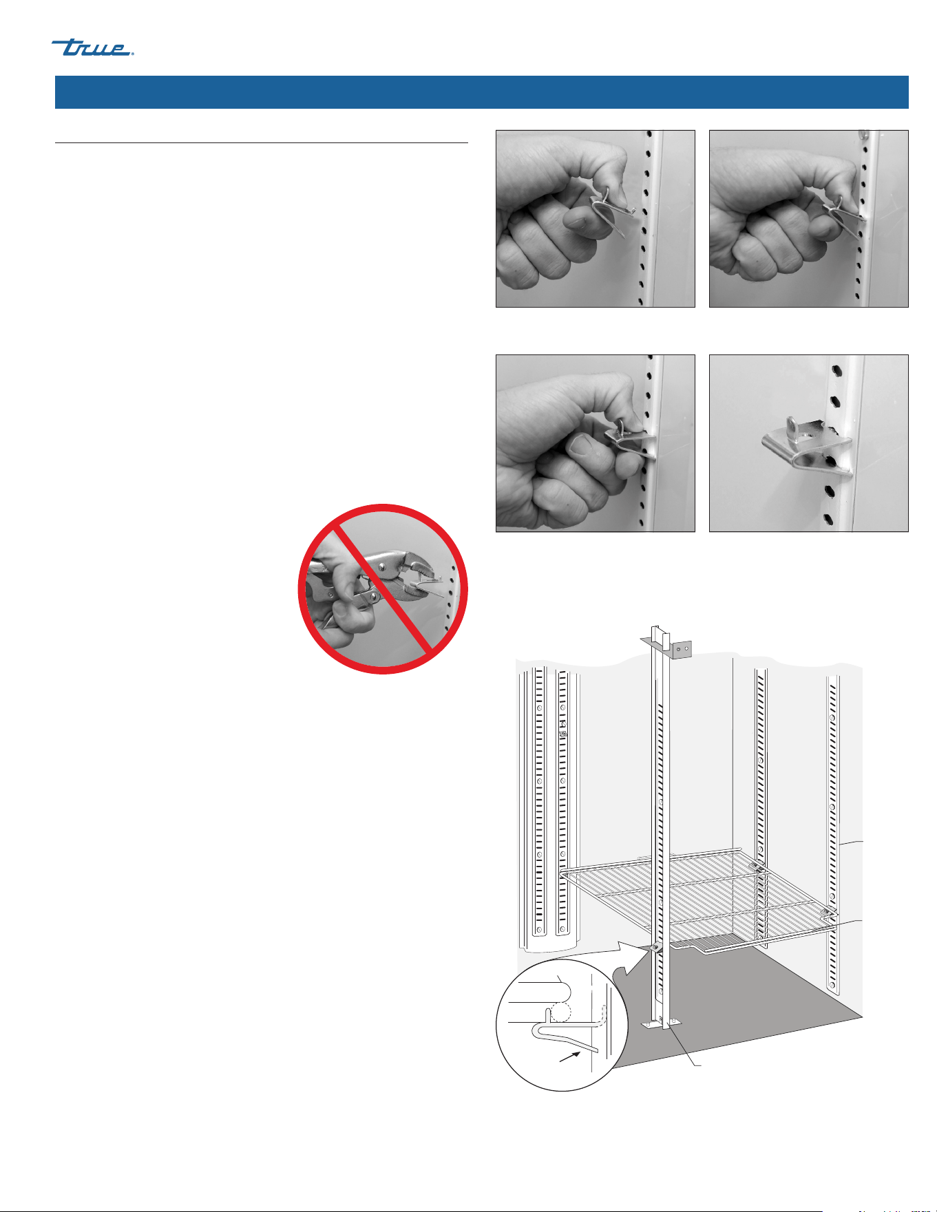
WARNING – DO NOT use pliers or
any crimping tools when installing
shelf clips. Altering shelf clips in any
way can lead to shelving instability.
Shelf Installation
Procedure
1. Hook the shelf clips into the shelf standards. See fig. 1.
2. Push up on the bottom of the clip. See fig. 2.
NOTE: You may need to squeeze or twist the bottom of the
shelf clip for proper installation. Position all four shelf clips
equal in distance from the floor for flat shelves.
3. Ensure the shelf clip is not loose or able to wiggle out of the
shelf standard. See figs. 3 and 4.
4. Place the shelves on the shelf clips with the cross support bars
facing down.
NOTE: Be sure all shelf corners are properly seated.
Installation Tips
• Install all the shelf clips before installing any shelves.
• Start at the bottom shelf and work your way up.
• Always lay the back of each shelf down on the rear clips before
the front.
Shelf Adjustment
Shelving is adjustable for customer application. This cabinet meets
the IEC Shelf Weight Capacity of 47lb/ft2
(230kg/m2).
Fig. 1. Installing top tab of shelf clip. Fig. 2. The bottom tab of the shelf clip
will fit tightly
Fig. 3. You may need to squeeze or twist
the bottom of the shelf clip to install.
Fig. 4. Installed shelf clip..
TBR
|
TDR SERIES www.truemfg.com
TEC_TM_043 | REV. F | EN03/2/2023 Page 10 of 40 P#803294
Cabinet Setup (cont.)
Draft Tower Installation
Procedure
1. Position the rubber washer (see fig. 1) over the mounting holes
in the cabinet countertop.
2. Thread the beer line connector (see fig. 2) to the draft arm.
See fig. 3.
3. Run the beer line through the hole and into the cabinet.
See fig. 4.
4. With the provided hardware, install the draft arm. See figs. 5
and 6.
5. Remove the top of the draft arm. See fig. 7a.
6. Insert the air hose [1” (25.4mm) plastic tube] into the draft arm.
See fig. 7b.
NOTE: Take care to not disturb the insulation.
7. Hook the air hose clip to the insulating sleeve at the top of the
draft arm. See fig. 8.
NOTE: The clip ensures the chill hose, which keeps the beer
faucet cold, remains correctly positioned.
8. Replace the top of the draft arm.
A B
Fig. 5. Ensure the rubber gasket is
between the countertop and draft
arm.
Fig. 6. Thread the handle onto the
beer draft arm.
Fig. 1. Draft arm components; draft
arm not shown.
Fig. 2. Be sure to insert the O-ring into
the beer line connector.
Fig. 3. Attach the beer line connector
to the draft arm.
Fig. 4. Run the line into the cabinet.
Fig. 7. Route the air hose through the draft tower from below.
Fig. 8. Hang the chill hose clip over the beer line.
TBR
|
TDR SERIES
TEC_TM_043 | REV. F | EN
03/2/2023
Page 11 of 40
www.truemfg.com
Cabinet Setup (cont.)
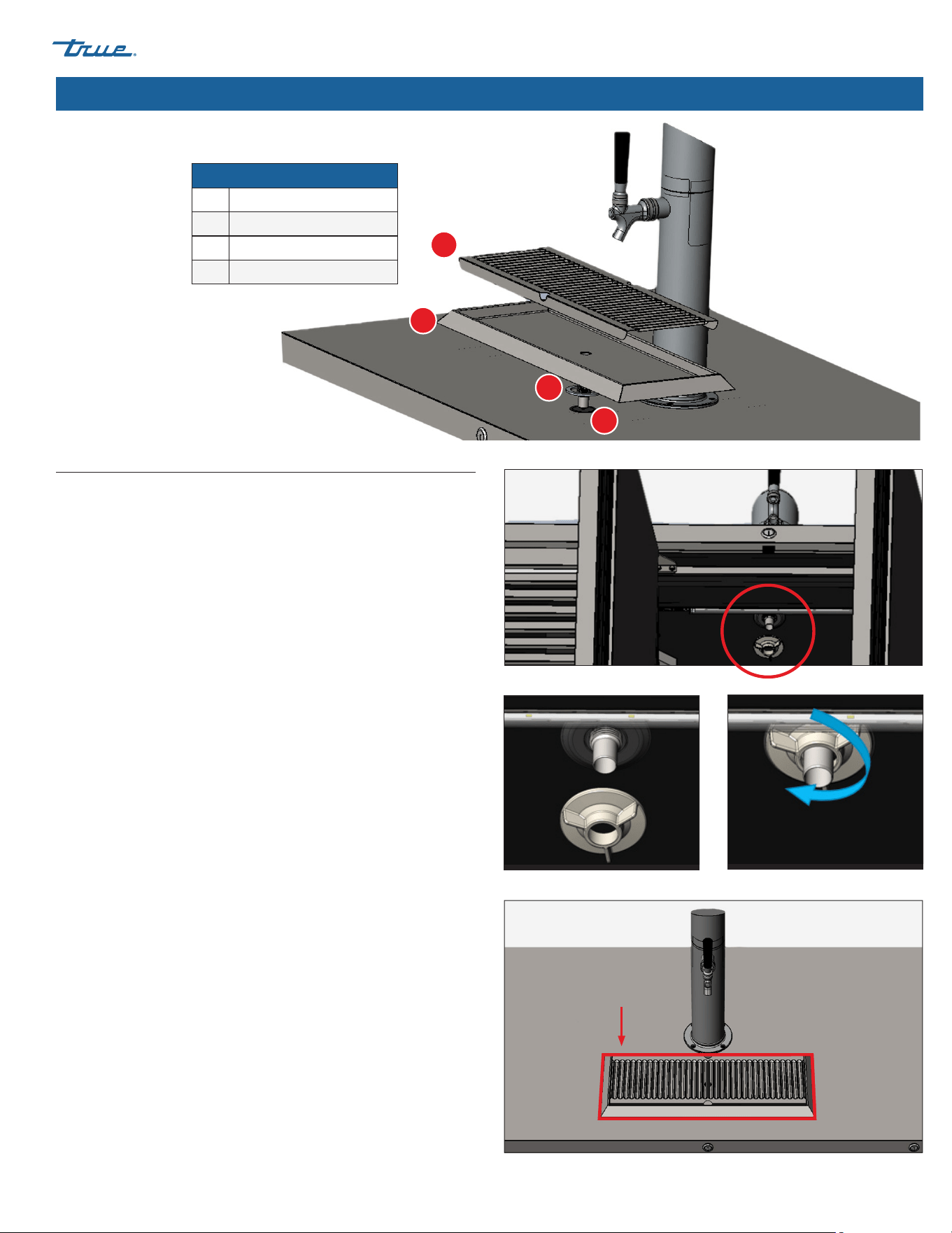
Draft Spill Tray
Procedure
1. Place the tray gasket over the spill tray tube.
2. Slide the spill tray tube into the spill tray access port.
3. Carefully position the spill tray on the countertop.
4. From the inside of the cabinet, thread the spill tray tube nut
onto the tube securing the spill tray to the countertop. See
figs. 1–3.
NOTE: Hand tighten only.
5. Place the spill tray grate into the spill tray.
6. Place a 3/4" (19 mm) i.d. hose onto the spill tray tube.
7. With the draft spill tray positioned and secured, apply a
bead of RTV Silicone (provided) to seal the spill tray to the
countertop. See fig. 4.
Parts Key
A Spill Tray Grate
B Spill Tray
C Tray Gasket
D Spill Tray Access Port
Fig. 1. Spill tray tube nut installation location.
Fig. 2. Thread the spill tray tube nut.
Fig. 3. Hand-tighten only.
Fig. 4. Apply silicone around the spill tray.
A
B
C
D
TBR
|
TDR SERIES www.truemfg.com
TEC_TM_043 | REV. F | EN03/2/2023 Page 12 of 40 P#803294
Cabinet Setup (cont.)
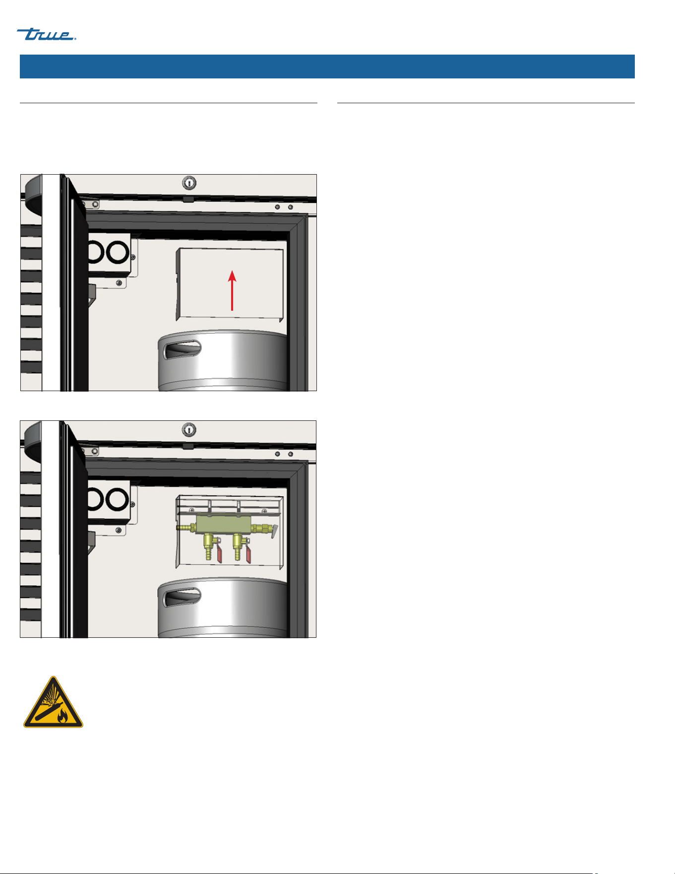
Air Distributor Manifold & Distributor Cover
A 2-way air distributor manifold is included to allow a single CO₂
supply line to pressurize two kegs. The air distributor is located
behind the distributor cover. To access, lift the cover off the
manifold mounting bracket. See figs. 1 and 2.
WARNING – Contents under pressure. Take care
when handling filled CO₂ tanks. If unfamiliar
with using CO₂ tanks and/or regulators, seek
information from your local distributor or brewer
representative before proceeding.
Fig. 1. LIft the distributor cover.
Fig. 2. The 2-way distributor manifold.
CO2 & Keg Connections
NOTE: CO2 cylinders, regulators, and keg tappers are not
provided by TRUE.
Required Tools
Required tools include (but may not be limited to) the following:
• CO2 Cylinder
• Pressure Regulator
• Tapper
NOTE: Be sure to use hose clamps for all air and beer lines as
applicable.
Procedure
1. Attach a pressure regulator to your CO2 cylinder.
2. Connect the pressure regulator to the distributor manifold.
3. Connect the distributor manifold to your tapper(s).
4. Connect the draft tower beer line(s) to your tapper(s).
5. Attach the tapper(s) to your keg(s).
6. Open the pressure regulator valve and pressurize the system.
NOTE: It requires 1/2 lb (0.23 kg) of CO2 to dispense a half-
barrel of beer at 38˚F (3.3˚C) with 15 psi (1.03 bar) of pressure
on the barrel.
7. Engage your tapper(s)
8. Check all connection points for leaks. If the system leaks, verify
all fittings and clamps are tight and seal correctly.
TBR
|
TDR SERIES
TEC_TM_043 | REV. F | EN
03/2/2023
Page 13 of 40
www.truemfg.com
Cabinet Setup (cont.)
Access Ports
Access ports provide optional locations to route external beer lines,
CO₂ lines, or overflow beer spill tray drain lines.
Carefully drill through the access port's inner and outer sleeves.
Once the lines have been routed, seal around the line with food
grade silicone.
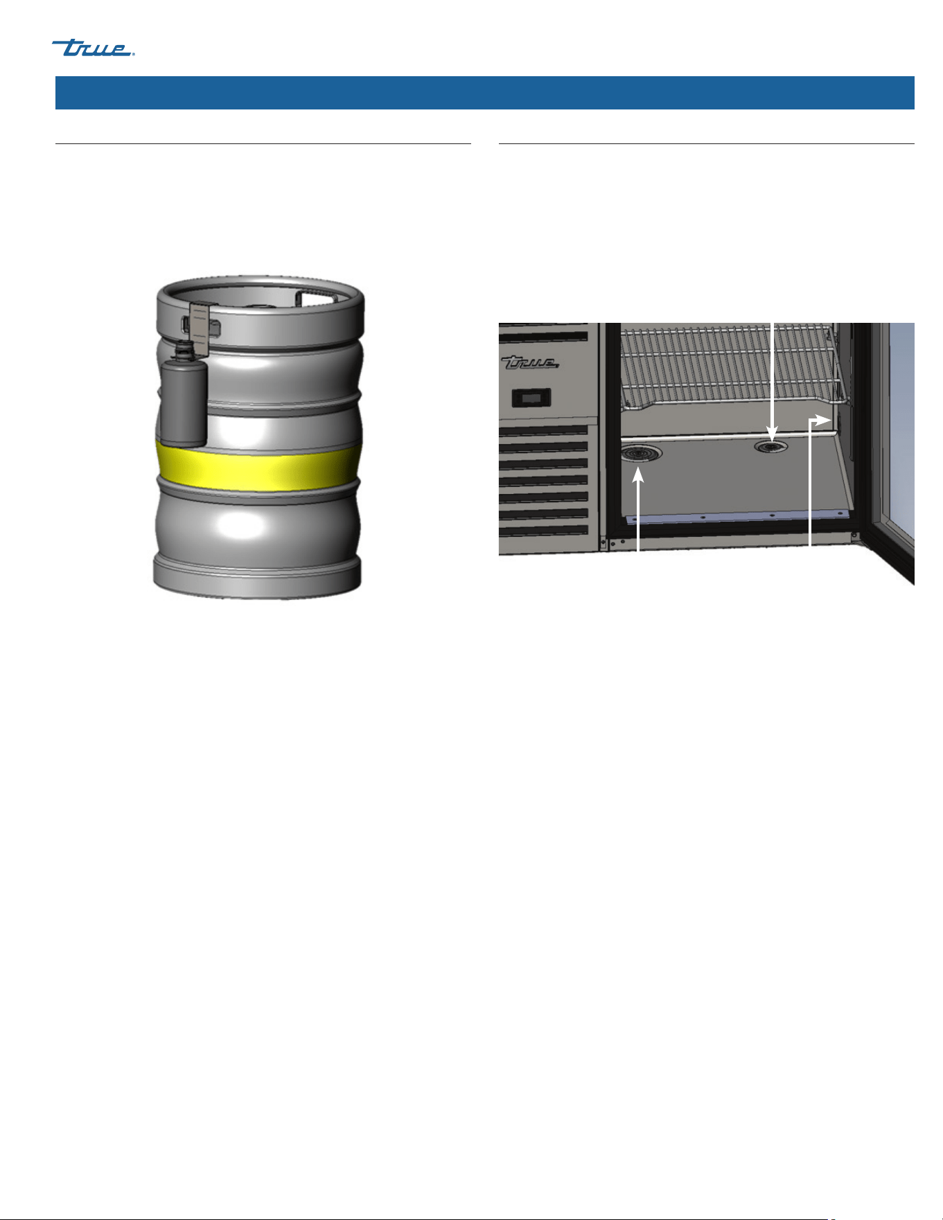
Beer Drain Bottle & Hanger
An optional beer drain bottle and hanger may be purchased to
collect the overflow from the draft spill tray. The bottle hanger
slides over the top of the beer keg. See fig. 3.
Route a 3/4" (19 mm) I.D. vinyl hose from the spill tray tube into the
drain bottle. Empty the bottle as determined by usage.
Fig. 3. Drain bottle and hanger on keg.
Standard small-floor
opposite evaporator cover.
Standard large-floor
next to evaporator cover.
Standard small-side wall
opposite evaporator cover.
TBR
|
TDR SERIES www.truemfg.com
TEC_TM_043 | REV. F | EN03/2/2023 Page 14 of 40 P#803294
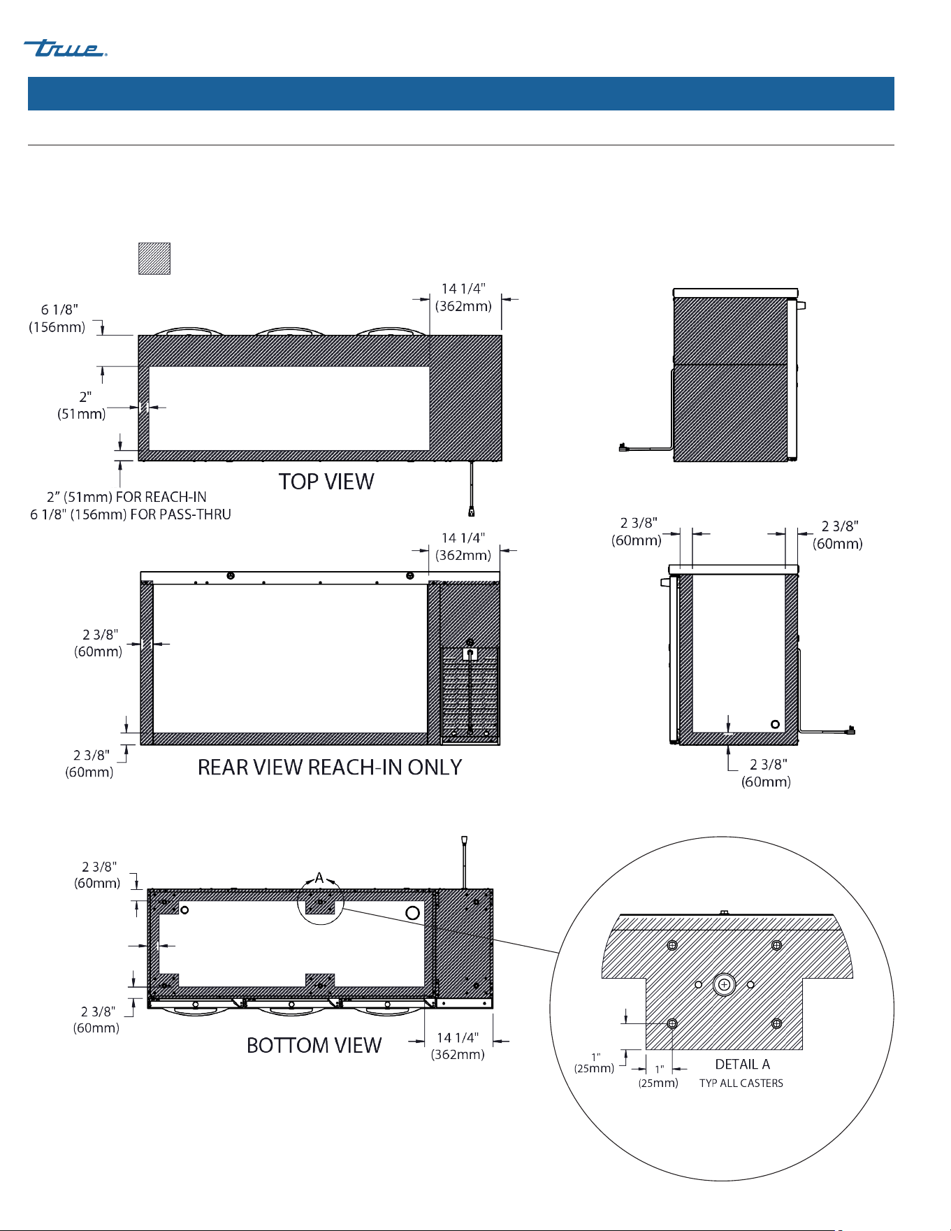
Cabinet Setup (cont.)
Access Ports (cont.)
NO DRILLING ALLOWED
Mirror dimensions for right-hand cooling systems
CONDENSING UNIT SIDE VIEW
NON-CONDENSING UNIT SIDE VIEW
DRILL ZONES* –
No drilling allowed on any face with doors!
Access ports are available for purchase to plug drilled holes.
*Applies to all sizes. 3-door model shown.
TBR
|
TDR SERIES
TEC_TM_043 | REV. F | EN
03/2/2023
Page 15 of 40
www.truemfg.com
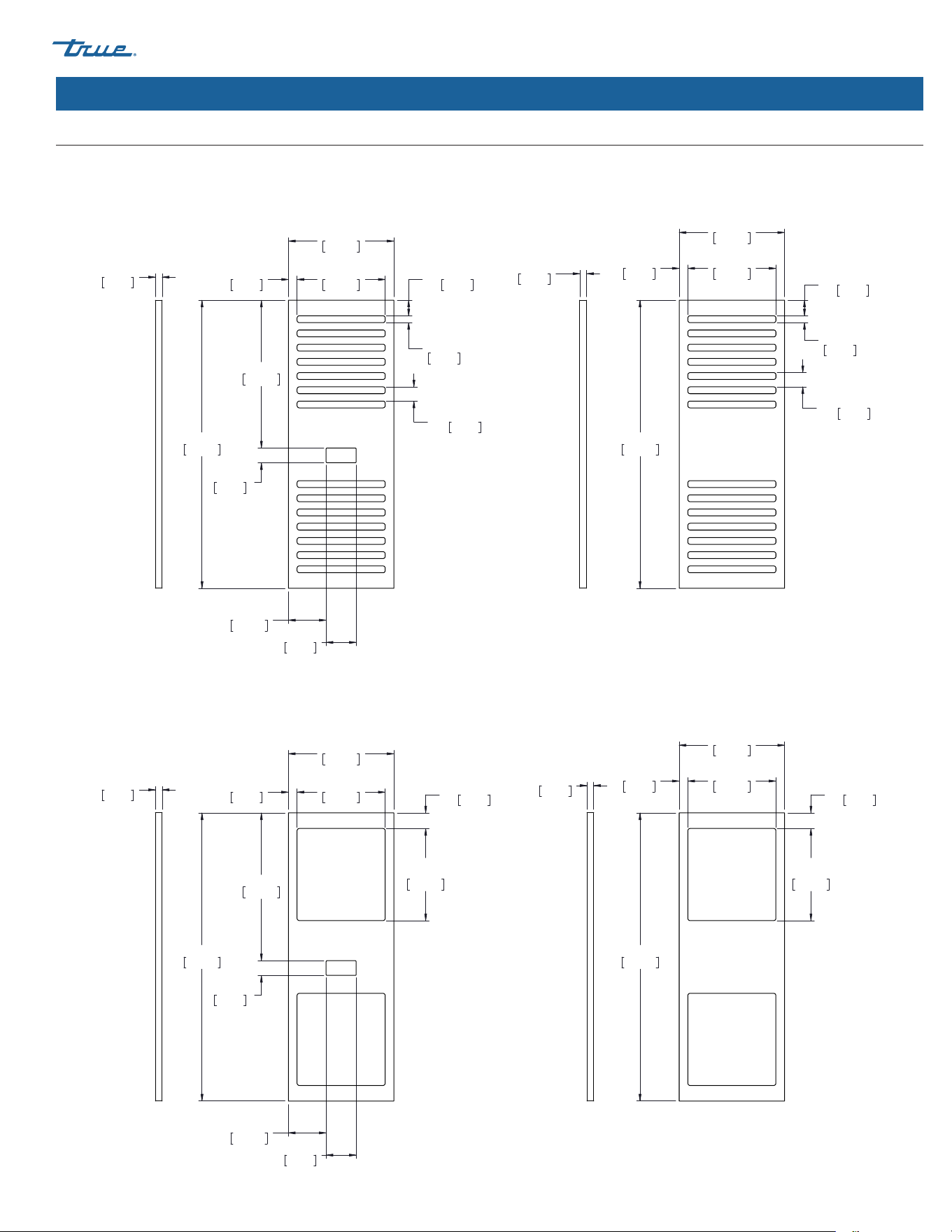
Overlay Panel Specifications
For panel installation instructions, see “Overlay Panel Installation” on page 19.
Slotted Grill
Cabinet Setup (cont.)
Grill with Holes
FRONT
FRONT
BACK
BACK
11 19/32"
294mm
31 11/16"
805mm
16 1/4"
413mm
1 5/8"
41mm
4 5/32"
105mm
3 5/16"
84mm
2X
1 23/32"
44mm
9 11/16"
246mm
31/32"
24mm
2X
10 1/8"
257mm
3/4"
19mm
11 19/32"
294mm
31 11/16"
805mm
2X
1 23/32"
44mm
9 11/16"
246mm
31/32"
24mm
2X
10 1/8"
257mm
3/4"
19mm
05/24/22
11 19/32"
294mm
31 11/16"
805mm
16 1/4"
413mm
1 5/8"
41mm
4 5/32"
105mm
3 5/16"
84mm
2X
1 23/32"
44mm
14X
3/4"
19mm
9 11/16"
246mm
31/32"
24mm
12X
1 9/16"
40mm
3/4"
19mm
11 19/32"
294mm
31 11/16"
805mm
2X
1 23/32"
44mm
14X
3/4"
19mm
9 11/16"
246mm
31/32"
24mm
12X
1 9/16"
40mm
3/4"
19mm
05/24/22

TBR
|
TDR SERIES www.truemfg.com
TEC_TM_043 | REV. F | EN03/2/2023 Page 16 of 40 P#803294
Cabinet Setup (cont.)
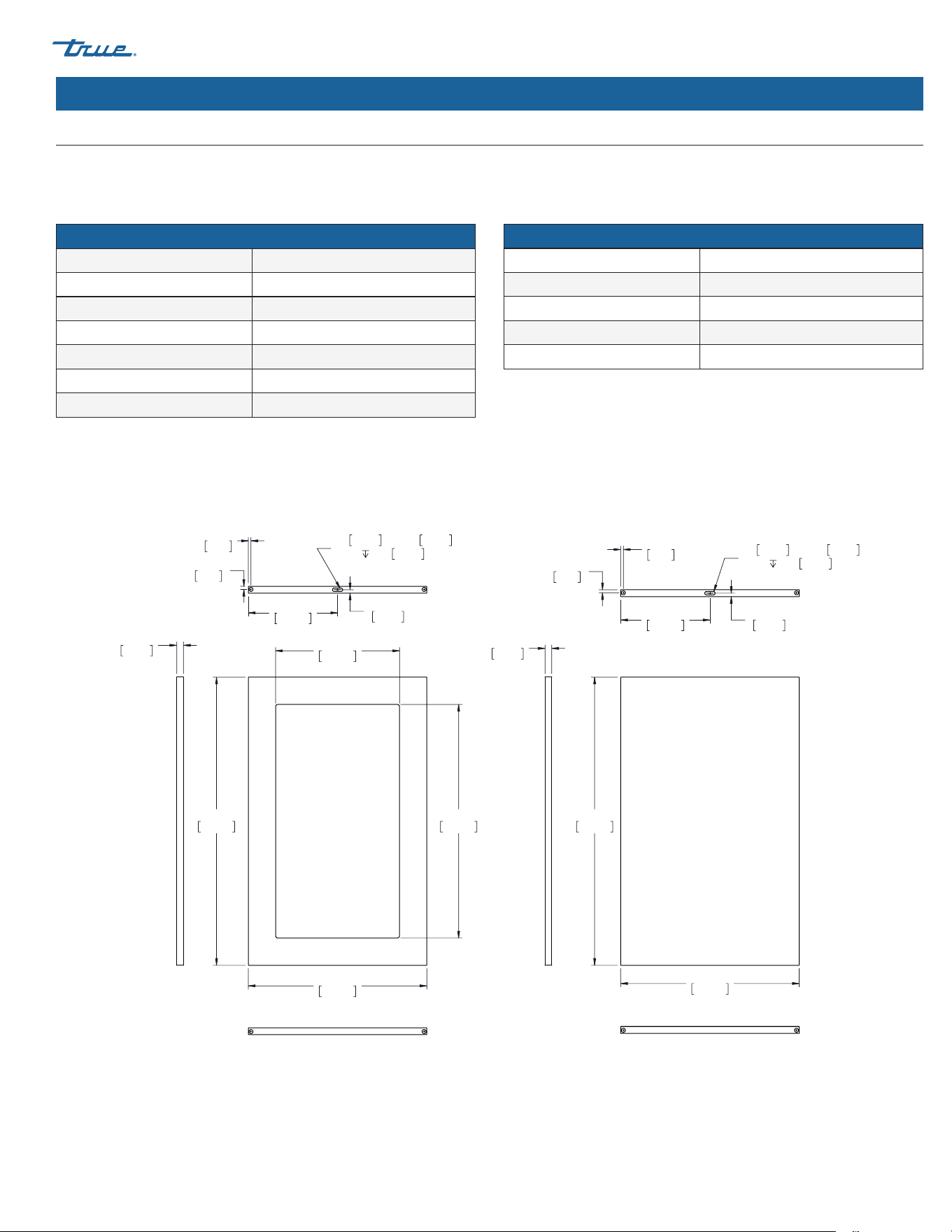
Overlay Panel Specifications (cont.)
For panel installation instructions, see “Overlay Panel Installation” on page 19.
17 5/8"
448mm
31 11/16"
805mm
11 5/8"
295mm
25 11/16"
652mm
3/8"
10mm
11/32"
9mm
9/32"
7mm
3/8"
10mm
X 1 1/8"
29mm
3/4"
19mm
8 13/16"
224mm
3/4"
19mm
31 11/16"
805mm
17 5/8"
448mm
3/4"
19mm
3/8"
10mm
11/32"
9mm
9/32"
7mm
3/8"
10mm
X 1 1/8"
29mm
3/4"
19mm
8 13/16"
224mm
05/24/22
GLASS DOOR SOLID DOOR
TBR | TDR–48
Glass Door Panel Specifications
Width 17-5/8" (448 mm)
Height 31-11/16" (805 mm)
Depth 3/4" (19 mm)
Weight 15 lb (6.8 kg) max
Rail Style Dimension 2" (50.8 mm) max
Viewable Area Height 25-11/16" (652 mm)
Viewable Area Width 11-5/8" (295 mm)
Solid Door Panel Specifications
Width 17-5/8" (448 mm)
Height 31-11/16" (805 mm)
Depth 3/4" (19 mm)
Weight 15 lb (6.8 kg) max
Rail Style Dimension 2" (50.8 mm) max
TBR
|
TDR SERIES
TEC_TM_043 | REV. F | EN
03/2/2023
Page 17 of 40
www.truemfg.com
Cabinet Setup (cont.)
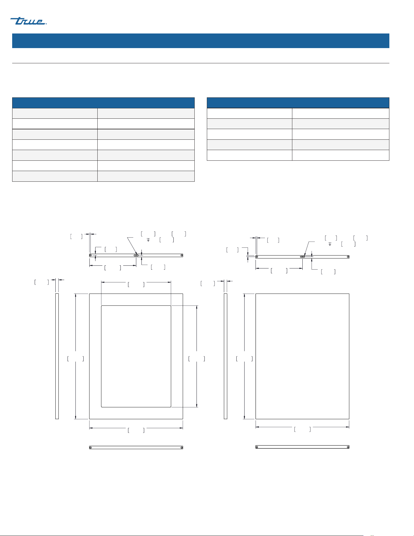
Overlay Panel Specifications (cont.)
For panel installation instructions, see “Overlay Panel Installation” on page 19.
19 5/8"
498mm
31 11/16"
805mm
13 5/8"
346mm
25 11/16"
652mm
3/8"
10mm
11/32"
9mm
9/32"
7mm
3/8"
10mm
X 1 1/8"
29mm
3/4"
19mm
9 13/16"
249mm
3/4"
19mm
31 11/16"
805mm
19 5/8"
498mm
3/4"
19mm
3/8"
10mm
11/32"
9mm
9/32"
7mm
3/8"
10mm
X 1 1/8"
29mm
3/4"
19mm
9 13/16"
249mm
05/24/22
GLASS DOOR SOLID DOOR
TBR | TDR–32/52/72/92
Glass Door Panel Specifications
Width 19-5/8" (498 mm)
Height 31-11/16" (805 mm)
Depth 3/4" (19 mm)
Weight 15 lb (6.8 kg) max
Rail Style Dimension 2" (50.8 mm) max
Viewable Area Height 25-11/16" (652 mm)
Viewable Area Width 13-5/8" (346 mm)
Solid Door Panel Specifications
Width 19-5/8" (498 mm)
Height 31-11/16" (805 mm)
Depth 3/4" (19 mm)
Weight 15 lb (6.8 kg) max
Rail Style Dimension 2" (50.8 mm) max
TBR
|
TDR SERIES www.truemfg.com
TEC_TM_043 | REV. F | EN03/2/2023 Page 18 of 40 P#803294
Cabinet Setup (cont.)
Overlay Panel Specifications (cont.)
For panel installation instructions, see “Overlay Panel Installation” on page 19.
23 5/8"
600mm
31 11/16"
805mm
17 5/8"
448mm
25 11/16"
652mm
3/8"
10mm
11/32"
9mm
9/32"
7mm
3/8"
10mm
X 1 1/8"
29mm
3/4"
19mm
11 13/16"
300mm
3/4"
19mm
31 11/16"
805mm
23 5/8"
600mm
3/4"
19mm
13/32"
10mm
11/32"
9mm
9/32"
7mm
5/16"
8mm
X 1 1/8"
29mm
3/4"
19mm
11 13/16"
300mm
05/24/22
GLASS DOOR SOLID DOOR
TBR | TDR–36/60/84/108
Glass Door Panel Specifications
Width 23-5/8" (600 mm)
Height 31-11/16" (805 mm)
Depth 3/4" (19 mm)
Weight 15 lb (6.8 kg) max
Rail Style Dimension 2" (50.8 mm) max
Viewable Area Height 25-11/16" (652 mm)
Viewable Area Width 17-5/8" (448 mm)
Solid Door Panel Specifications
Width 23-5/8" (600 mm)
Height 31-11/16" (805 mm)
Depth 3/4" (19 mm)
Weight 15 lb (6.8 kg) max
Rail Style Dimension 2" (50.8 mm) max
TBR
|
TDR SERIES
TEC_TM_043 | REV. F | EN
03/2/2023
Page 19 of 40
www.truemfg.com
Cabinet Setup (cont.)
Required Tool(s)
• Surface Protection*
• Phillips Screwdriver
• 2+ Clamps [≥2” (50.8 mm)]
• 5/16" Socketwrench
• 5/8" (15.8751 mm) Screws**
• Tape Measure
• Marking Utensil
• Tape
• 3/8" Drill Bit
• 17/64" Drill Bit
• Drill
TAKE CARE TO NOT DAMAGE THE PANEL FINISH!
This instruction demonstrates using cardboard from the
unit’s exterior packaging for surface protection.
Recommended panel thickness is 3/4" (19.05 mm).
Fig. 1. Pull the top of the cover forward
and then lift.
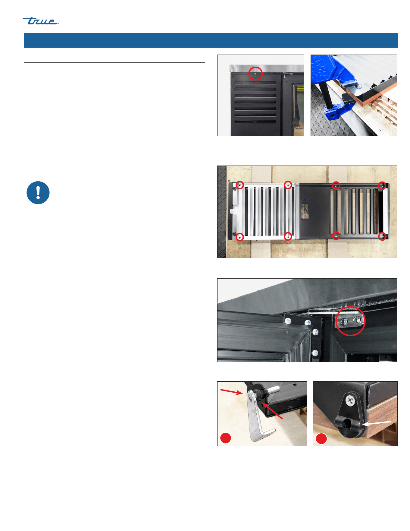
Grill Overlay Installation
Procedure
1. Carefully lay the grill overlay panel facedown on a protected
surface.
2. With a Phillips screwdriver, remove the cabinet grill. See fig. 1.
3. Place the grill facedown on the overlay panel. Then, center the
grill and overlay. See fig. 2.
NOTE: Center the cabinet grill and overlay panel at the
corners.
4. Clamp the grill and overlay. See fig. 2.
NOTE: If the clamp jaws are not padded, insert padding
between the clamp and the overlay to protect the panel’s
finish.
5. Fasten the overlay to the grill. See fig. 3.
NOTE: Be sure the mounting screws are shorter than the
overlay panel thickness.
6. Remove the clamps, and then reinstall the grill.
Fig. 2. Center the overlay and grill at the
corners. The panel is slightly larger than
the grill.
Fig. 3. Cabinet grill predrilled hole locations.
Fig. 4. Carefully remove the door from the unit.
*Cardboard, moving blanket, foam padding, etc.
** Required quantities vary by application. Be sure the screws are shorter
than the panel thickness.
Fig. 5. Remove the top hinge pin & bushing (A) and the door cam riser (B) from the
hinge brackets. Do not remove the hinge brackets.
A
B
Overlay Panel Installation
Overlay units are custom order.
Glass & Solid Door Overlay Installation
Procedure
1. Carefully lay the door overlay panel facedown on a protected
surface.
2. With a 5/16" socketwrench, remove the cabinet door. See fig. 4.
3. Remove the door gasket, top hinge pin & bushing (fig. 5a), and
door cam riser (fig. 5b).
4. Place the door facedown on the overlay. Then, center the door
and overlay. See fig. 6.
NOTE: Center the door and overlay panel at the corners.
TBR
|
TDR SERIES www.truemfg.com
TEC_TM_043 | REV. F | EN03/2/2023 Page 20 of 40 P#803294
Cabinet Setup (cont.)
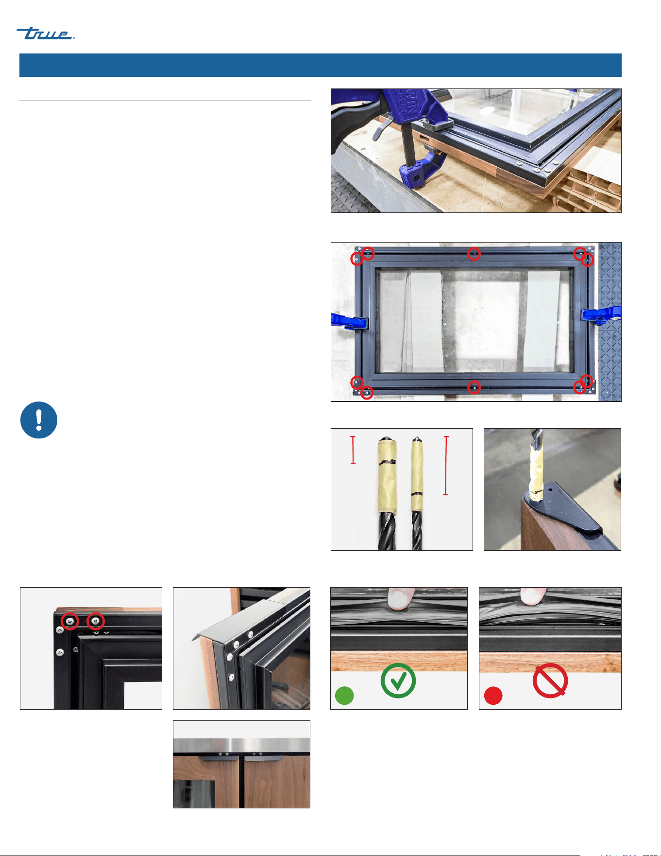
Procedure (cont.)
5. Clamp the door and panel. See fig. 6.
NOTE: If the clamp jaws are not padded, insert padding
between the clamp and the overlay to protect the panel’s
finish.
6. Fasten the overlay to the door (see fig. 7). Then, remove
the clamps.
NOTE: Be sure the mounting screws are shorter than
the panel width.
7. Mark the drill bits with the measures below. See fig. 8.
a. 3/8" bit at 1/2" (25.4 mm)
b. 17/64" bit at 1-1/8" (28.575 mm)
8. Carefully drill holes for both hinges as described below.
See fig. 9.
a. Drill the 3/8" hinge bushing/cam hole.
b. At the center of the bushing hole, drill the 17/64" hinge
pin hole.
NOTE: Drill the hinge pin hole until the mark reaches
the hinge bracket, not the bottom of the bushing hole.
See fig. 9.
Be sure to drill straight down to prevent
cracking the overlay and/or drilling through
the side.
9. With the existing hardware, install the door handle(s).
See figs. 10 and 11.
10. Install the hinge components.
11. Install the gasket.
NOTE: Verify the gasket is fully seated in the gasket
channel. See fig. 12.
12. Install the door assembly. Verify the door closes correctly
and the gasket seals without gaps. Repeat the process for
each door.
Fig. 6. Be sure the overlay’s center slot is positioned at the top of the door.
Fig. 7. Cabinet door predrilled hole locations.
Fig. 12. Pull the side of the gasket to check its installation.
A: CORRECT; gasket channel is NOT visible.
B: INCORRECT; gasket channel is visible.
Fig. 10. Handle screw locations.
Fig. 11. Installed door handles.
B
A
1/2"
(12.7 mm)
Bushing /
Cam Hole
1-1/8"
(28.575 mm)
Pin Hole
Fig. 8. Mark the hole depths on the drill
bits.
Fig. 9. Drill the 3/8" hole first.
THEN drill the 17/64" hole.
Overlay Panel Installation (cont.)
TBR
|
TDR SERIES
TEC_TM_043 | REV. F | EN
03/2/2023
Page 21 of 40
www.truemfg.com
Cabinet Operation
Startup
• The compressor is ready to operate when the unit is purchased.
All you need to do is plug in the cooler.
• Excessive tampering with the control could lead to service
difficulties. If replacing the temperature control is ever needed,
be sure to order the replacement from your TRUE dealer or
recommended service agent.
• Good air flow inside your TRUE unit is critical. Take care to
prevent product from pressing against the sides or back
wall and coming within 4" (101.6 mm) of the evaporator
housing. Refrigerated air off the evaporator coil must circulate
throughout the cabinet for even product temperatures.
NOTE: If the unit is disconnected or shut off, wait 5 minutes
before restarting.
RECOMMENDATION – Before loading product, run your TRUE
unit empty for 24 hours to verify proper operation. Remember,
our factory warranty DOES NOT cover product loss!
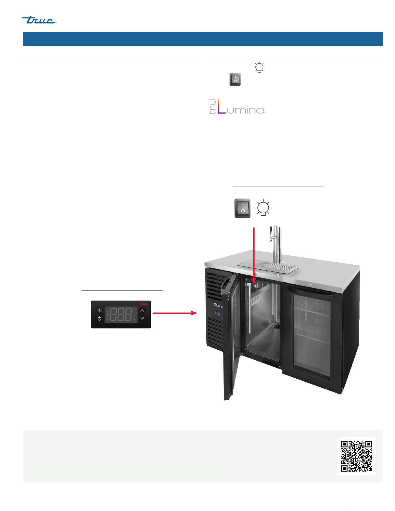
Factory Installed TruLumina LED
To change the display color of the TruLumina LEDs, toggle the light
switch off and then on. Repeat to cycle trough all available colors.
Leaving the light switch in the "off" position for two
seconds will turn off the lights.
Electronic Temperature Control
On the front of grill.
ECO
°C
°F
Light Switch on Glass Door Models
Inside the top ceiling.
Temperature Control & Light Switch Location
The light symbol
shows the approximate location of the light
switch.
FOR MORE INFORMATION
For more information regarding a cabinet's temperature control adjustment or general sequence of operation,
please see our Temperature Control Adjustment—Sequence of Operation Manual in our resource library at
https://www.truemfg.com/Service-Manuals/Sequence-of-Operation or follow the QR code.

TBR
|
TDR SERIES www.truemfg.com
TEC_TM_043 | REV. F | EN03/2/2023 Page 22 of 40 P#803294
Cabinet Operation (cont.)
General Sequence of Operation: Refrigerator and Freezer Cabinets
When the cabinet is plugged in
• Interior lights will illuminate on glass door models (see previous page for light switch location).
• An electronic control with digital display will illuminate (if installed).
• There may be a short delay before the compressor and/or evaporator fan(s) start. This delay may be determined by time or by
temperature, which could be the result of an initial defrost event that will last at least 6 minutes.
• The temperature control/thermostat may cycle the compressor and evaporator fan(s) on and off together. Every cabinet will
require a defrost event to ensure the evaporator coil remains clear of frost and ice buildup. Defrost is initiated by a defrost timer or
by the electronic control.
EXCEPTION – Models TSID, TDBD, TCGG, and TMW do not have an evaporator fan(s).
• The temperature control/thermostat senses either an evaporator coil temperature or air temperature, NOT product temperature.
• An analog thermometer, digital thermometer, or electronic control display may reflect the refrigeration cycle swings of up and
down temperatures, NOT product temperature. The most accurate method to determine a cabinet's operation is to verify
the product temperature.
• Refrigerators with mechanical temperature controls will defrost during every compressor off-cycle.
• Freezers with mechanical temperature controls will defrost by time initiation as determined by a defrost timer.
EXCEPTION – Models TFM, TDC, THDC and TMW require a manual defrost. The frequency of this manual defrost will
depend on the cabinet's usage and ambient conditions.
• An electronic control with a digital display (if installed) will show def during defrost.
NOTE: The display may have a short delay before showing a temperature after a defrost event has expired and instead
show def during a refrigeration cycle.
• Models with an analog or digital thermometer may show higher than normal temperatures during defrost.
• A refrigerator will use the evaporator fans to clear the coil during defrost.
EXCEPTION – Models TSID, TDBD, and TCGG do not have an evaporator fan(s).
• A freezer will use heaters to clear the evaporator coil during defrost.
NOTE: The evaporator coil heater and drain tube heater are only energized during defrost. Defrost is terminated when a
specific evaporator coil temperature is reached or by a time duration.

TBR
|
TDR SERIES
TEC_TM_043 | REV. F | EN
03/2/2023
Page 23 of 40
www.truemfg.com
Cabinet Operation (cont.)
Pressure
Dispensing pressures differ based on the following:
• Draft dispensing line length.
• Draft dispensing system type.
• Actual product (pressure requirements vary).
• Product temperature.
• Pressurizing agent: Air pressure, CO₂ or special blended gases.
Helpful Hints on Maintaining the Correct Pressure
• Know which pressurizing agent to use on which product, and
why.
• Monitor your regulators to ensure applied pressure remains
constant.
• Keep equipment in good repair.
Tapping
DO NOT agitate the kegs unnecessarily. If excessive agitation
occurs, allow kegs to settle 1 to 2 hours before tapping.
Prior to tapping the keg, ensure all beer faucets in the serving
location are in the off position. Completely remove the dust cover
(identification cap) from the keg.
DRAFT BEER SHOULD BE TREATED AS A FOOD PRODUCT.
In most instances draft beer is not pasteurized. It is very
important that you store and handle it properly.
Follow these steps to ensure the highest quality and consumer
satisfaction.
• Immediately store draft beer in a refrigerated cabinet.
• Draft beer products have a recommended shelf life. If you have
questions regarding the shelf life of any of your draft products,
please consult with your supplying depot or respective brewer
representative.
• Store kegs separately from food products. If your cooler is used
to refrigerate draft and food products, DO NOT store food near
or on the kegs.
• Keep keg storage and dispensing areas clean to prevent any
possibility of contaminating your draft products.
Temperature
Correct temperature is a key factor in storing and dispensing draft
beer. Beer that is too cool or too warm may be subject to flavor
loss, off taste and dispensing problems.
Helpful Hints for Controlling Temperature
• Keep a thermometer handy.
• Monitor the draft temperature in the cooler and at the tap.
• Keep cooler door closed as much as possible to avoid
temperature fluctuation.
• Regular maintenance of refrigeration equipment is
recommended.
Draft Beer Storage, Handling & Operation

TBR
|
TDR SERIES www.truemfg.com
TEC_TM_043 | REV. F | EN03/2/2023 Page 24 of 40 P#803294
Cabinet Operation (cont.)
To minimize draft beer problems, always follow the recommended
instructions for temperature and CO₂ pressures from your beer
supplier.
Flat Beer
Foamy head disappears quickly. Beer lacks usual zestful,
brewery-fresh flavor.
• CO₂ turned off when not in use.
• Contaminated air source (associated with compressed air).
• Greasy glasses.
• Not enough pressure.
• Pressure shut off during night.
• Loose tap or vent connection.
• Sluggish pressure regulator.
• Obstruction in lines.
False Head
Large soap-like bubbles, head dissolves very quickly.
• Dry glasses.
• Improper pour.
• Pressure required does not correspond to beer temperature.
• Coils or direct draw beer lines warmer than beer in keg.
• Small lines into large faucet shanks.
• Beer drawn improperly.
Wild Beer
Beer, when drawn, is all foam and not enough liquid beer.
• Beer drawn improperly.
• Faucet in bad or worn condition.
• Kinks, dents, twists or other obstructions in line.
• Traps in beer lines.
• Beer too warm in kegs or lines.
• Too much pressure.
• Creeping gauge causing too much pressure.
Cloudy Beer
Beer in the glass appears hazy, not clear.
• Dirty glass or faucet.
• Beer over-chilled.
• Beer temperature variance in keg (beer may have warmed
up at some time).
• Hot spots in beer lines.
• Cutting beer through faucet.
• Beer line in poor condition.
• Dirty lines.
• Beer that has been frozen.
Bad Taste
• Dirty faucet.
• Old or dirty beer lines.
• Failure to flush beer lines with water after each empty keg.
• Unsanitary conditions at bar.
• Foul air or dirt in lines.
• Oily air; greasy kitchen air.
• Temperature of package too warm.
• Dry glasses.
Draft Beer Problems & Troubleshooting
TBR
|
TDR SERIES
TEC_TM_043 | REV. F | EN
03/2/2023
Page 25 of 40
www.truemfg.com
Cabinet Operation (cont.)
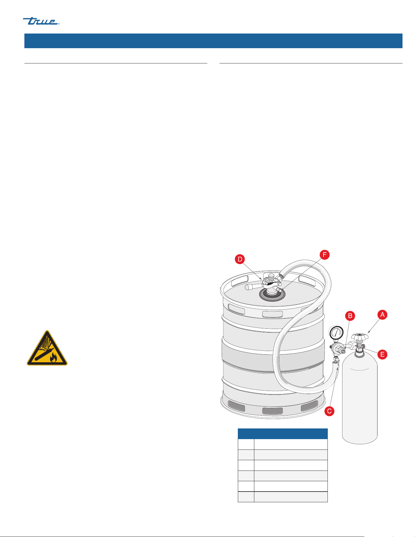
Changing CO₂ Gas Cylinder
CAUTION – Always follow these instructions when you replace
a CO₂ gas cylinder:
Procedure
1. Close cylinder valve A.
2. Remove tap head D from the barrel. Pull the pressure release
ring on the body of the tap to release pressure remaining in
the line (DO NOT close regulator shut-off C).
3. Remove or loosen regulator key B by turning counter
clockwise.
4. Remove the regulator from used cylinder at outlet E.
5. Remove the dust cap from new gas cylinder at outlet E and
clear dust from the outlet by opening and closing valve A
quickly using appropriate wrench.
6. Attach the regulator to the new cylinder at outlet E (use new
fiber/plastic washer, if required).
7. Completely open valve A.
8. Close valve C.
9. Adjust regulator key B by turning clockwise to set pressure.
Check setting by opening C and pulling and releasing the ring
F on the pressure release valve on the body of the tap.
10. Tap the barrel at D with valve C open.
NOTE:
• Don't lay CO₂ cylinders flat.
• Don't drop CO₂ cylinders.
• It requires 1/2 lb. (0.23 kg) of CO₂ to dispense a half-barrel of
beer at 38˚F (3.3˚C) with 15 psi (1.03 bar) of pressure on the
barrel.
Pressure Adjustment on CO₂ Regulator
Increasing Pressure
Procedure
1. Close regulator shut-off C.
2. Turn the regulator key B clockwise and adjust setting.
3. Tap the gauge for an accurate reading.
4. Open regulator shut-off C and draw beer.
Decreasing Pressure
Procedure
1. Close regulator shut-off C.
2. Untap the barrel at D and to bleed line, activate the tap
handle. Leave it in the open position.
3. Slowly open regulator shut-off C and simultaneously turn
regulator key B counter-clockwise to zero reading.
4. Close regulator shut-off C and set pressure by turning regulator
key B clockwise. Check the setting by opening and closing
valve C.
5. Close the tap head D (put in OFF position).
6. Tap the barrel at D and open regulator shut-off C.
WARNING – Contents under pressure. Take
care when handling filled CO₂ tanks. If unfamiliar
with using CO₂ tanks and/or regulators, seek
information from your local distributor or brewer
representative before proceeding.
Parts Key
A Cylinder Valve
B Regulator Key
C Regulator Shut-off
D Tap Head
E CO₂ Cylinder Outlet
F Ring
TBR
|
TDR SERIES www.truemfg.com
TEC_TM_043 | REV. F | EN03/2/2023 Page 26 of 40 P#803294
Maintenance, Care & Cleaning
Draft Tower Cleaning
Regardless of design, draught dispensers must be cleaned
regularly. Flushing the draught dispenser with only water is not
enough to maintain cleanliness. True recommends cleaning the
draught dispenser whenever changing to a fresh keg.
Clean dispensers ensure your draught beer will be at its best when
served. Although the beer in the barrel is in excellent condition,
the beer can become less satisfying if drawn through a beer line
and faucet that are not kept clean.
NOTE: Use cleaners approved by your beer supplier and follow
their instructions. If you are using the cleaning kit purchased
from TRUE, follow the instructions below:
Prepare Solution
Add 1/2 oz. (14.2 g) of cleaning solution to each quart of warm
water. Fill the pump bottle with the mixed cleaning solution.
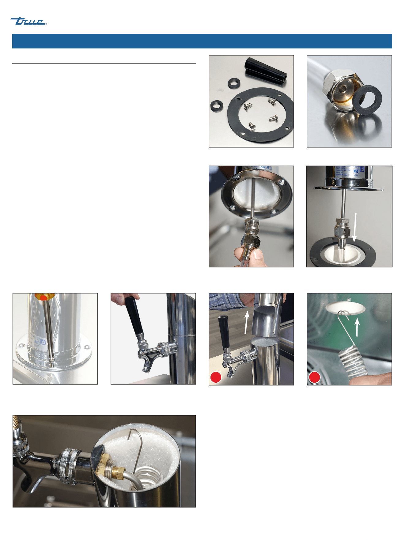
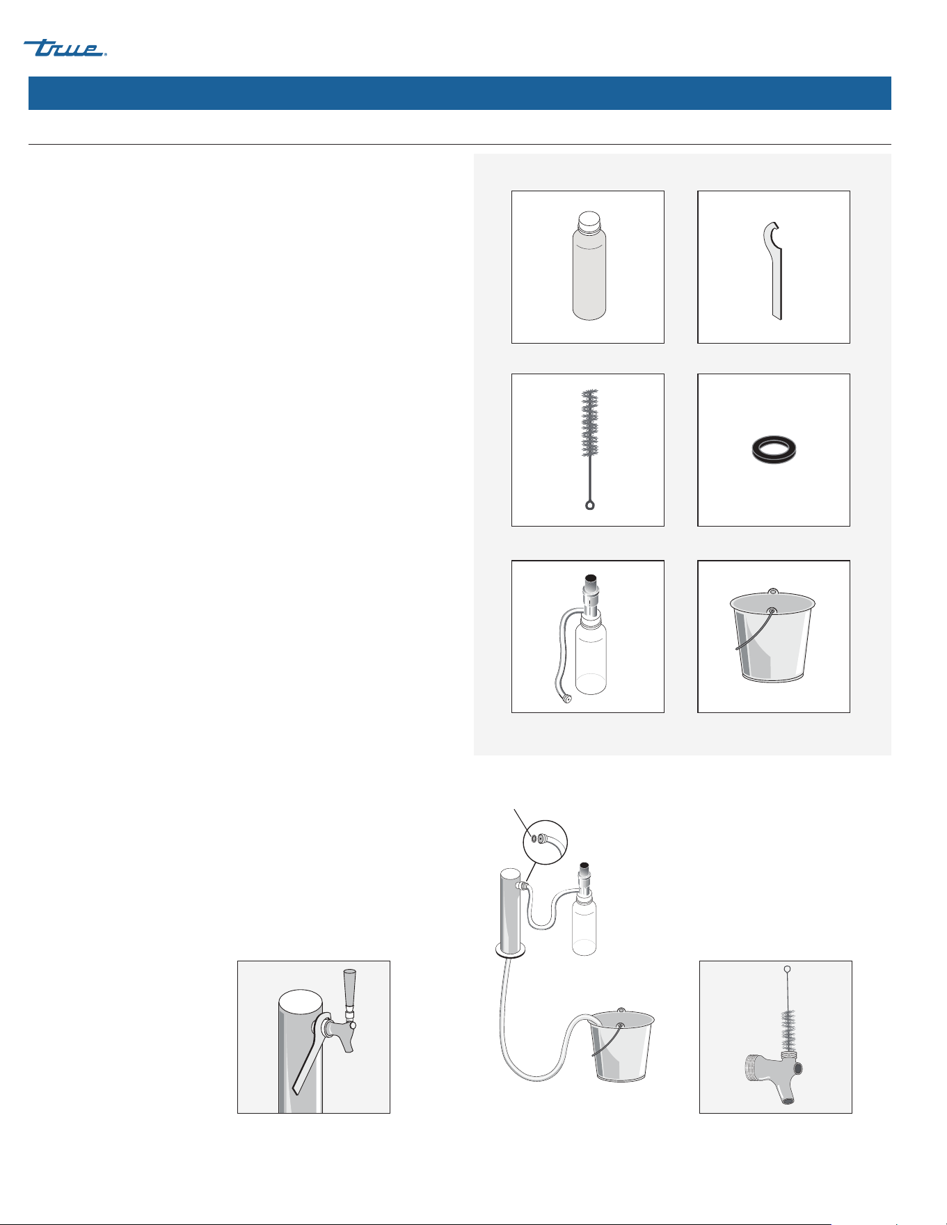
Procedure
1. Shut-off the CO₂ at the regulator.
2. Remove the tapping device (keg coupler) from the keg.
3. Unscrew the handle the from faucet.
4. Remove the beer faucet with the spanner wrench; turn the
faucet clockwise to remove. See fig. 1.
5. Put the tap and faucet parts in a bucket.
6. Thread the pump bottle hose to the beer column tap outlet
and allow the beer line to drain in the bucket. See fig. 2.
NOTE: Be sure the rubber gasket is in place to prevent leaks.
7. Pump the solution from the bottle through the beer line(s) and
into the bucket. Wait 10 minutes while the cleaning solution
works through the lines.
8. With the supplied brush, clean the beer faucet parts. See fig. 3.
9. Rinse all parts thoroughly.
10. Rinse the bucket, pump bottle and hose thoroughly with clean
cool water.
11. Fill the pump bottle with clean cool water and pump water
through lines until it runs clear. Repeat as necessary.
12. After the water runs clear, assemble and install the faucet. Then
re-tap the keg.
Beer Tap Cleaning Kit – Required Tools
BLC System Cleaner
Brush
Pump Bottle & Tube
Spanner Wrench
Rubber Gasket
Bucket & Fresh Water
Rubber
Gasket
Fig. 1. Carefully remove the faucet. Fig. 2. Drain the beer from the line. Fig. 3. Thoroughly clean the faucet
components.
TBR
|
TDR SERIES
TEC_TM_043 | REV. F | EN
03/2/2023
Page 27 of 40
www.truemfg.com
Maintenance, Care & Cleaning (cont.)
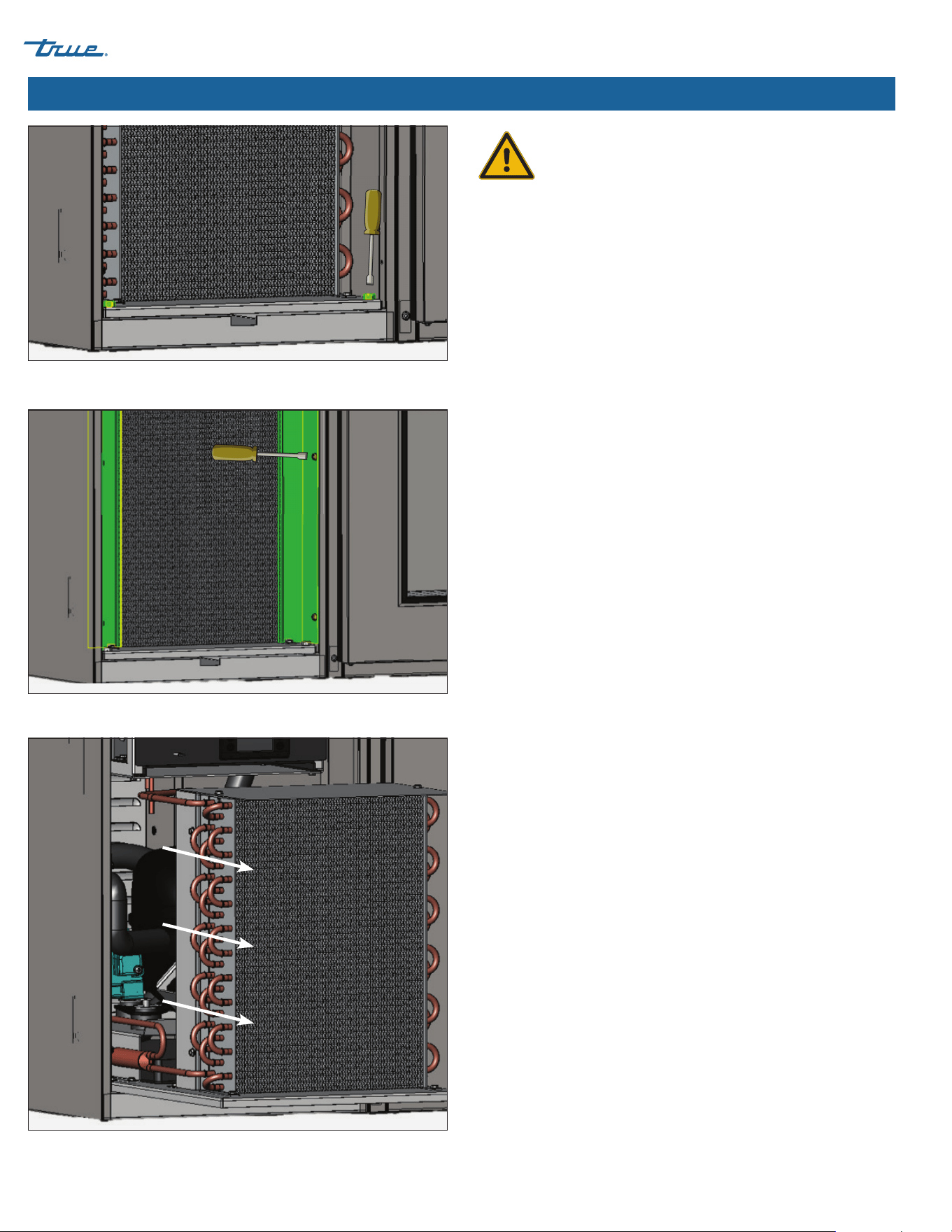
CAUTION - Take care during operation, maintenance or repairs
to avoid cuts or pinching from any cabinet part/component.
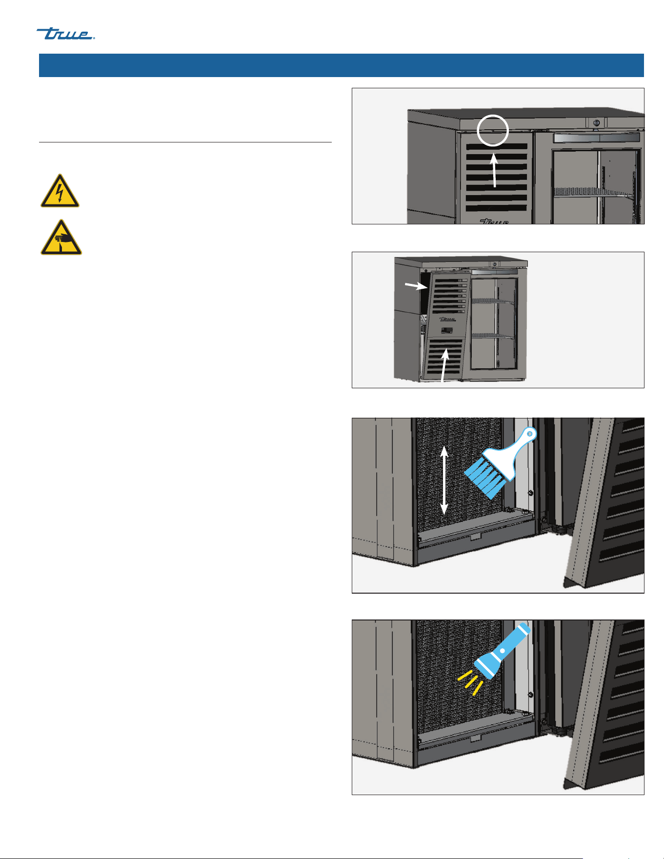
Condenser Coil Cleaning
When using electrical appliances, basic safety precautions should
be followed, including the following:
WARNING – DO NOT clean appliance with a pressure
washer or hose.
CAUTION – Fins are sharp. Caution must be used to
avoid eye injury. Eye protection is recommended.
Tools Required
• 1/4" nut driver
• 3/8" nut driver
• Stiff bristle brush
• Tank of compressed air
• Vacuum cleaner
• Flashlight
• Eye protection
Procedure
1. Disconnect power to unit.
2. Remove the screw securing the louvered grill to the cabinet.
See fig. 1.
3. Pull on the grill assembly to release it from the magnetic
brackets. See fig. 2.
4. Carefully clean off accumulated dirt from the front fins of the
condensing coil with a stiff bristle brush. See fig. 3.
5. With dirt removed from the surface of the coil, use a flashlight
to verify that you can see through the coil and observe the
condenser fan blade spinning. See fig. 4.
If the view is clear, reinstall louvered grill, connect unit to
power and verify operation.
If the view is still blocked with dirt, proceed to step 6.
6. Remove the condenser base bolts. See fig. 5.
7. Remove the condenser coil brackets. See fig. 6.
8. Carefully slide the condensing unit out (tubing connections are
flexible). See fig. 7. Gently blow compressed air or CO₂ through
the coil until it is clean.
9. Carefully vacuum any dirt around and behind the condensing
unit area.
10. Carefully slide the compressor assembly back into position and
replace the bolts.
11. Reinstall the louvered grill, connect power to the unit, and
verify operation.
Fig. 3. Never brush across the coil fins.
Fig. 2. Pull the grill forward before lifting up.
Fig. 4. Verify all blockages have been removed.
Fig. 1. Louver grill screw location.
TBR
|
TDR SERIES www.truemfg.com
TEC_TM_043 | REV. F | EN03/2/2023 Page 28 of 40 P#803294
Maintenance, Care & Cleaning (cont.)
Fig. 7. Carefully slide the condensing unit out.
Fig. 6. Remove the coil brackets.
Fig. 5. Remove the condensing base bolts.
Important Warranty Information
THE CLEANING OF THE CONDENSER IS NOT
COVERED BY WARRANTY!
If you have any questions, please contact your local
TRUE Manufacturing Service Department. See the front cover for
locations and contact information.
• Condenser coils accumulate dirt and require cleaning every 30
days or as needed.
• A dirty condenser coil can result in non-warranted repairs and/
or cabinet failure.
• Proper cleaning involves removing dust from the condenser by
using a soft brush, vacuuming the condenser with a shop vac,
or using CO₂, nitrogen or pressurized air.
• Do not place any filter material in front of the condensing coil.
• On most units, the condenser is accessible by removing the
cabinet's outer grill cover.
• If you cannot remove the dirt adequately, please contact your
licensed refrigeration service provider.

TBR
|
TDR SERIES
TEC_TM_043 | REV. F | EN
03/2/2023
Page 29 of 40
www.truemfg.com
Maintenance, Care & Cleaning (cont.)
Stainless Steel Care & Cleaning
CAUTION – DO NOT use any steel wool, abrasive or chlorine-
based products to clean stainless steel surfaces.
Stainless Steel Opponents
There are three basic things which can break down your stainless
steel’s passivity layer and allow corrosion to form.
• Scratches from wire brushes, scrapers, steel pads, and other
items that can be abrasive to stainless steel’s surface.
• Deposits left on your stainless steel can leave spots. You may
have hard or soft water depending on what part of the country
you live in. Hard water can leave spots. Hard water that is
heated can leave deposits if left to sit too long. These deposits
can cause the passive layer to break down and rust your
stainless steel. All deposits left from food prep or service should
be removed as soon as possible.
• Chlorides which are present in table salt, food and water, as well
as in household and industrial cleaners. These are the worst
type of chlorides to use on stainless steel.
Stainless Steel Cleaning and Restoration
DO NOT use stainless steel cleaners or similar solvents to clean
plastic or powder-coated parts. Instead, use warm soapy water.
• For routine cleaning and removal of grease and oil, apply white
vinegar, ammonia, or any good commercial detergent* with a
soft cloth or sponge.
• Stainless steel polish (e.g., Zep® Stainless Steel Polish, Weiman®
Stainless Steel Cleaner & Polish, Nyco® Stainless Steel Cleaner
& Polish, or Ecolab® Ecoshine®) and olive oil can act as a barrier
against fingerprints and smears.
• Degreasers* (e.g., Easy-Off® Specialty Kitchen Degreaser or
Simple Green® Industrial Cleaner & Degreaser) are excellent for
removal of grease, fatty acids, blood and burnt-on foods on all
surfaces.
*
DO NOT
use detergents or degreasers with chlorides or phosphates.
• For restoration/passivation or removing stubborn stains and
discoloration, Brillo® Cameo®, Zud® Cleanser, Ecolab® Specifax™
First Impression® Metal Polish, Sheila Shine, or talc can be
applied by rubbing in the direction of the polish lines.
NOTE: The use of proprietary names is intended for example
only and does not constitute or imply an endorsement.
Omission of proprietary cleansers from this list does not imply
inadequacy.
8 Tips to Help Prevent Rust on Stainless Steel
Maintain the Cleanliness of Your Equipment
Avoid build-up of hard stains by cleaning frequently. Use
cleaners at the recommended strength (alkaline chlorinated or
non-chloride).
Use the Correct Cleaning Tools
Use non-abrasive tools when cleaning your stainless steel products.
The stainless steel’s passive layer will not be harmed by soft cloths
and plastic scouring pads.
Clean Along Polishing Lines
Polishing lines ("grain") are visible on some stainless steels. Always
scrub parallel to polishing lines when visible. Use a plastic scouring
pad or soft cloth when you cannot see the grain.
Use Alkaline, Alkaline-Chlorinated or Non-Chloride
Cleaners
While many traditional cleaners are loaded with chlorides, the
industry is providing an ever increasing choice of non-chloride
cleaners. If you are not sure of your cleaner’s chloride content,
contact your cleaner supplier. If they tell you that your present
cleaner contains chlorides, ask if they have an alternative.
Avoid cleaners containing quaternary salts, as they can attack
stainless steel, causing pitting and rusting.
Rinse
When using chlorinated cleaners, you must rinse and wipe dry
immediately. It is better to wipe standing cleaning agents and
water as soon as possible. Allow the stainless steel equipment to
air dry. Oxygen helps maintain the passivity film on stainless steel.
Never Use Hydrochloric Acid (Muriatic Acid) on
Stainless Steel
Even diluted, hydrochloric acid can cause corrosion, pitting and
stress corrosion cracking of stainless steel.
Water Treatment
To reduce deposits, soften hard water when possible. Installation
of certain filters can remove corrosive and distasteful elements.
Salts in a properly maintained water softener can also be to your
advantage. Contact a treatment specialist if you are not sure of the
proper water treatment.
Regularly Restore & Passivate Stainless Steel
Stainless steel gets its stainless properties from the protective
chromium oxides on its surface. If these oxides are removed by
scouring, or by reaction with harmful chemicals, then the iron in
the steel is exposed and can begin to oxidize, or rust. Passivation is
a chemical process that removes free iron and other contaminants
from the surface of stainless steel, allowing the protective
chromium oxides to re-form.
TBR
|
TDR SERIES www.truemfg.com
TEC_TM_043 | REV. F | EN03/2/2023 Page 30 of 40 P#803294
Cabinet Adjustments, Servicing & Component Replacement
NOTE: Any cabinet adjustments are to be made AFTER the
cabinet has been verified level and properly supported.
Servicing & Replacing Components
• Replace component parts with OEM (original equipment
manufacturer) components.
• Have a licensed service provider service your unit to minimize
the risk of possible ignition due to incorrect parts or improper
service and to ensure the operator's health and safety.
• Unplug the refrigerator/freezer before cleaning or making
any repairs. Setting temperature controls to the 0 position or
powering off an electronic control may not remove power
from all components (e.g., light circuits, perimeter heaters, and
evaporator fans).
Reverse Door Swing
Kit Contents (shipped with cabinet)
• Bottom hinge bracket
• Top hinge bracket
• Door cam base and riser
• Top hinge bushing
Required Tool(s)
• Phillips screwdriver
• 5/16" socket wrench
• Flat blade screwdriver
NOTE: Make cabinet adjustments after verifying the cabinet is
level and supported properly. The example shown is a left hinge
door changing to a right hinge door.
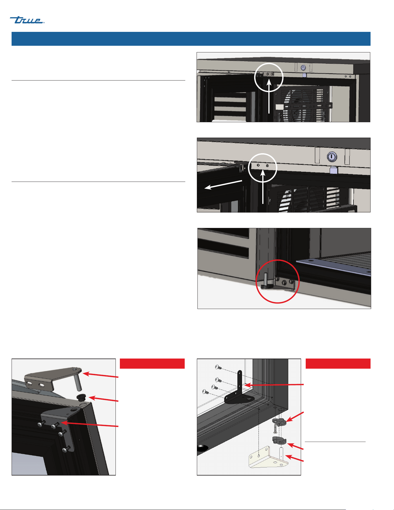
Procedure
1. Locate and remove the bolts securing the top hinge bracket to
the front of the cabinet base. Remove the bolts. See fig. 1.
2. With the bolts removed, swing the bracket onto the door.
Tilt the top of the door out to provide clearance from the
countertop. Lift the door to disengage it from the top hinge
bracket. See fig. 2.
3. Remove the bottom hinge assembly from the cabinet.
See fig. 3.
Top hinge bracket
and shaft
Top hinge bushing
Door bracket
Door Top
Door bracket
Door cam riser
Components not on the door
but included in the assembly.
Door cam base
Bottom hinge bracket
and shaft
Door Bottom
Fig. 1. Top hinge bolt locations.
Fig. 2. Remove the top hinge from the unit.
Fig. 3. Lift the door off the bottom hinge.
Fig. 4a. Top hinge components. Fig. 4b. Bottom hinge components.
TBR
|
TDR SERIES
TEC_TM_043 | REV. F | EN
03/2/2023
Page 31 of 40
www.truemfg.com
Cabinet Adjustments, Servicing & Component Replacement (cont.)
4. Remove all door hardware except the door
handle (see figs. 4a and 4b). Set the door
brackets aside.
NOTE: The door brackets are the only
hardware that will be relocated. All other
hardware is new and included in the kit.
Door brackets are reversible to the opposite
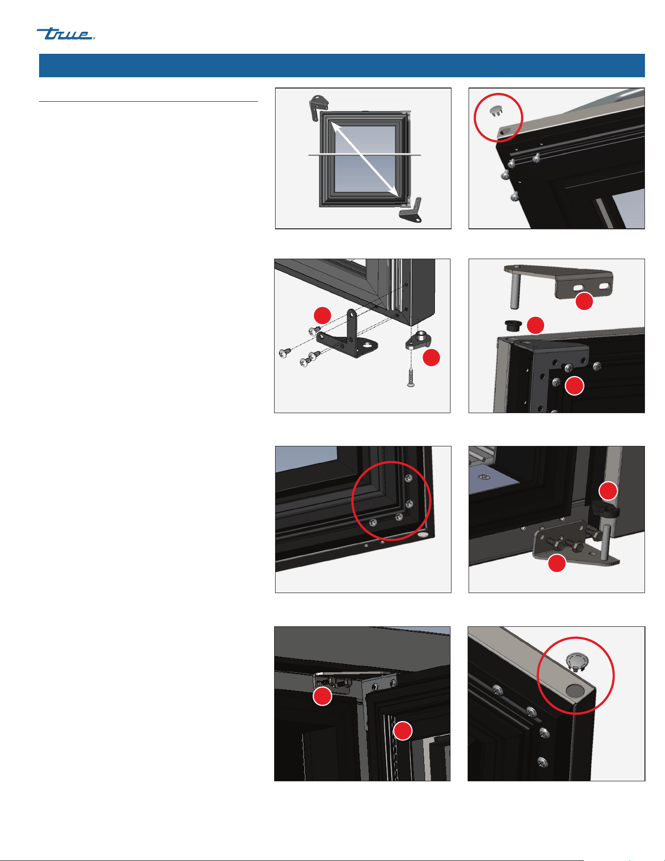
diagonal corner of the door. See fig. 5.
5. Remove any door plugs and all screws on
the opposite side of the original door hinge
placement. See fig. 6.
6. Install all hardware into the door's new
component locations.
Door Bottom (see fig. 7a)
a. Install the bottom door bracket.
b. Install the door cam riser.
Door Top (see fig. 7b)
a. Install the top door bracket.
b. Install the top hinge bushing.
c. Install top hinge bracket and shaft.
7. Insert the screws into the holes opposite their
original location. See fig. 8.
8. Install the bottom hinge bracket and shaft to
the cabinet. See fig. 9.
a. Install the door cam base to hinge shaft.
b. Lift door onto bottom door hinge bracket
and shaft.
9. Secure the top hinge bracket to the cabinet.
See fig. 10.
NOTE: Top hinge bracket is slotted for door
alignment.
10. Install plug in door in top of door (see fig. 11).
Verify correct door operation.
Fig. 6. The current bottom door bracket will be
the new top door bracket.
Fig. 5. Remove the door plugs and remaining
screws.
Fig. 7a. Bottom hinge component assembly. Fig. 7b. Top hinge component assembly.
Fig. 8. Move the hardware from step 5 to the side
opposite its original location.
Fig. 9. Install the bottom hinge pin in its new
location.
Fig. 10. Install the top hinge and the door. Fig. 11. Install the plug.
1
1
1
1
3
2
2
2
2
Reverse Door Swing (cont.)
TBR
|
TDR SERIES www.truemfg.com
TEC_TM_043 | REV. F | EN03/2/2023 Page 32 of 40 P#803294
Cabinet Adjustments, Servicing & Component Replacement (cont.)
CENTERED DOOR
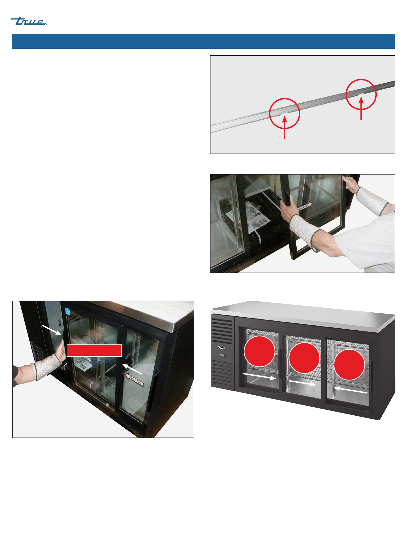
Fig. 1. Door channel openings.
Fig. 3. Two-Door Units: Position the front door at the center of the cabinet.
Fig. 4. Three-Door Units: Move the doors as directed to remove doors from channel.
Fig. 2. Carefully remove the door.
Slide Door Removal
DO NOT use the side latch before removing the slide door. The
tension on the door cord is needed to execute these operation
instructions.
The doors cannot be removed unless they are positioned as
described in the instructions below.
Procedure
1. Position the doors as described below. To remove, lift the
positioned door. Then, tilt the top of the door back until the
rollers exit the door channel. Then, swing the bottom of the
door out of the bottom channel. See figs. 1 and 2.
Two-Door Units
Center the front door on the cabinet opening. See fig. 3.
Three-Door Units See fig. 4
• Center Door: Slide 9” (228.6 mm) right
• Right Door: Slide 14” (355.6 mm) left
• Left Door: Slide 9-1/2” (241.3 mm) right
LEFT
9-1/2"
241.3
mm
CENTER
9"
228.6
mm
RIGHT
14"
355.6
mm
TBR
|
TDR SERIES
TEC_TM_043 | REV. F | EN
03/2/2023
Page 33 of 40
www.truemfg.com
Cabinet Adjustments, Servicing & Component Replacement (cont.)
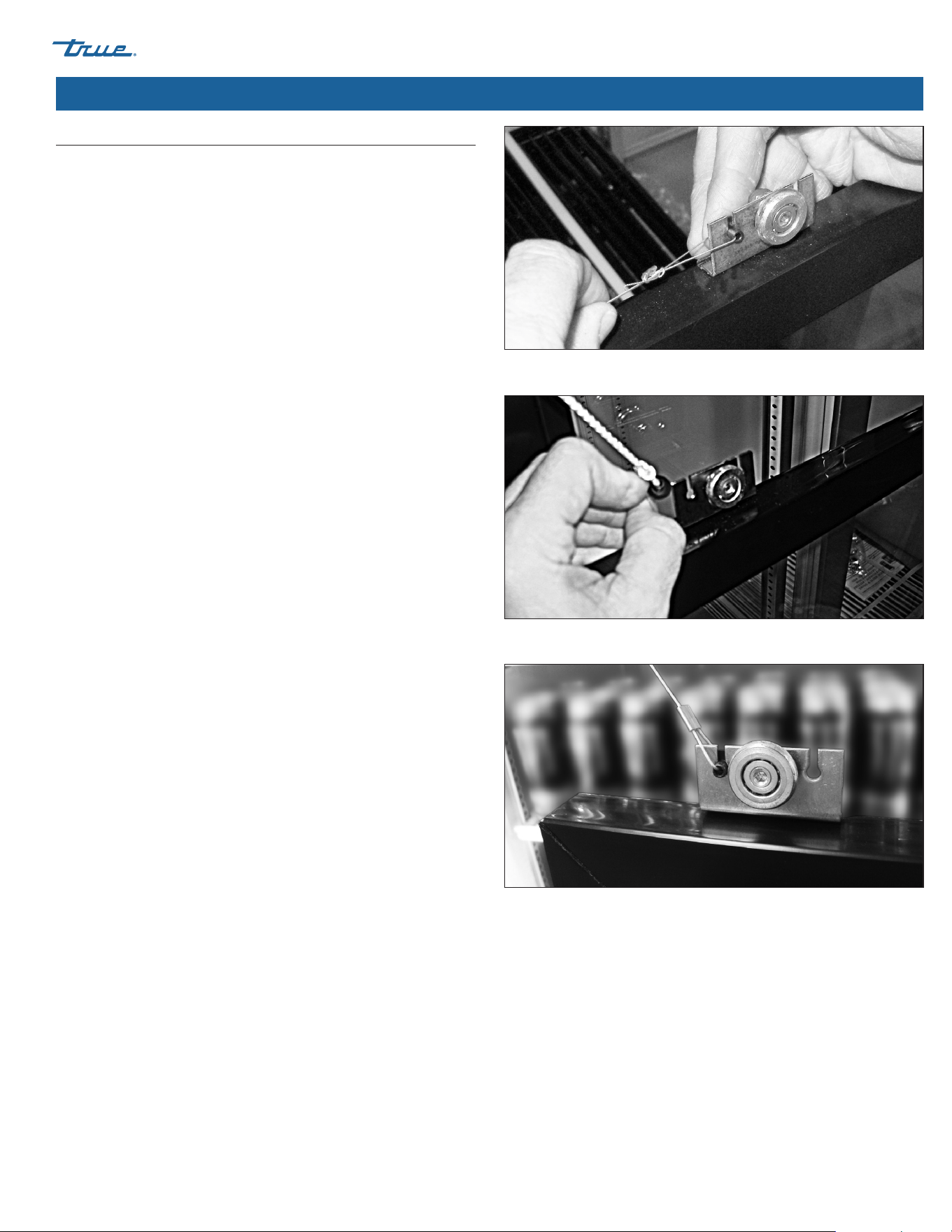
2. Remove the door cord from the roller bracket. See figs. 5 and 6.
NOTE: The black plastic tab holding the door cord slides out
the back.
3. Let the door cord slowly retract back into the door side
channel.
NOTE: When reinstalling the door, be sure the door cord
grommet attaches to roller slot closest to the pulley.
See fig. 7.
Slide Door Removal (cont.)
Fig. 5. Remove the door cord from the roller bracket.
Fig. 6. Slide the the black tab holding the door cord out the back
Fig. 7. Be sure the door cord is in the roller slot closest to the pulley.
TBR
|
TDR SERIES www.truemfg.com
TEC_TM_043 | REV. F | EN03/2/2023 Page 34 of 40 P#803294
Cabinet Adjustments, Servicing & Component Replacement (cont.)
Only adjust the cabinet after it has been installed in its final
location and correctly leveled.
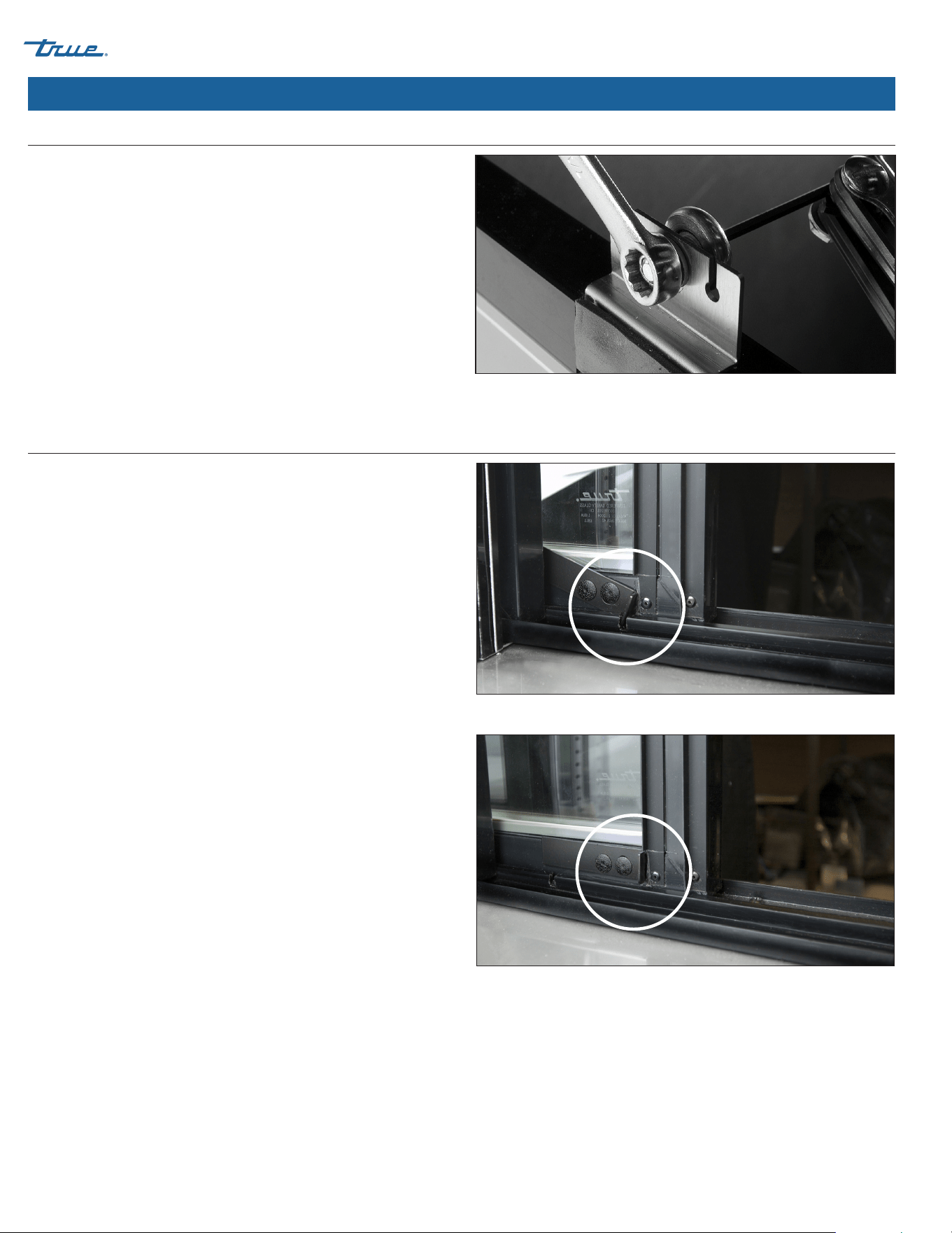
Procedure
1. Completely close the slide doors and check for openings. If
there are any gaps/openings between the closed doors and
cabinet, the doors will need to be adjusted.
2. With a 7/16" wrench or adjustable wrench and 1/8" Allen
wrench, loosen the roller and move it along the slotted hole.
After the adjustment has been made tighten the roller into
place. See fig. 1.
The hold-open feature keeps the door in the open position.
Procedure
1. Slide the door open.
2. Latch the door in the open position from the back side of door
(notch in track). See figs. 1 and 2.
NOTE: Figs. 1 and 2 show the rear view of the door and track.
Slide Door Operation – Hold-Open Feature
Fig. 1. Adjust the roller.
Fig. 1. Door latch is in the open position (engaged with notch).
Fig. 2. Door latch is in the closed position (disengaged from notch).
Slide Door Operation – Door Adjustment
TBR
|
TDR SERIES
TEC_TM_043 | REV. F | EN
03/2/2023
Page 35 of 40
www.truemfg.com
Cabinet Adjustments, Servicing & Component Replacement (cont.)
Gasket Replacement
Tools Required
• Caulk gun
• Black 100% silicone
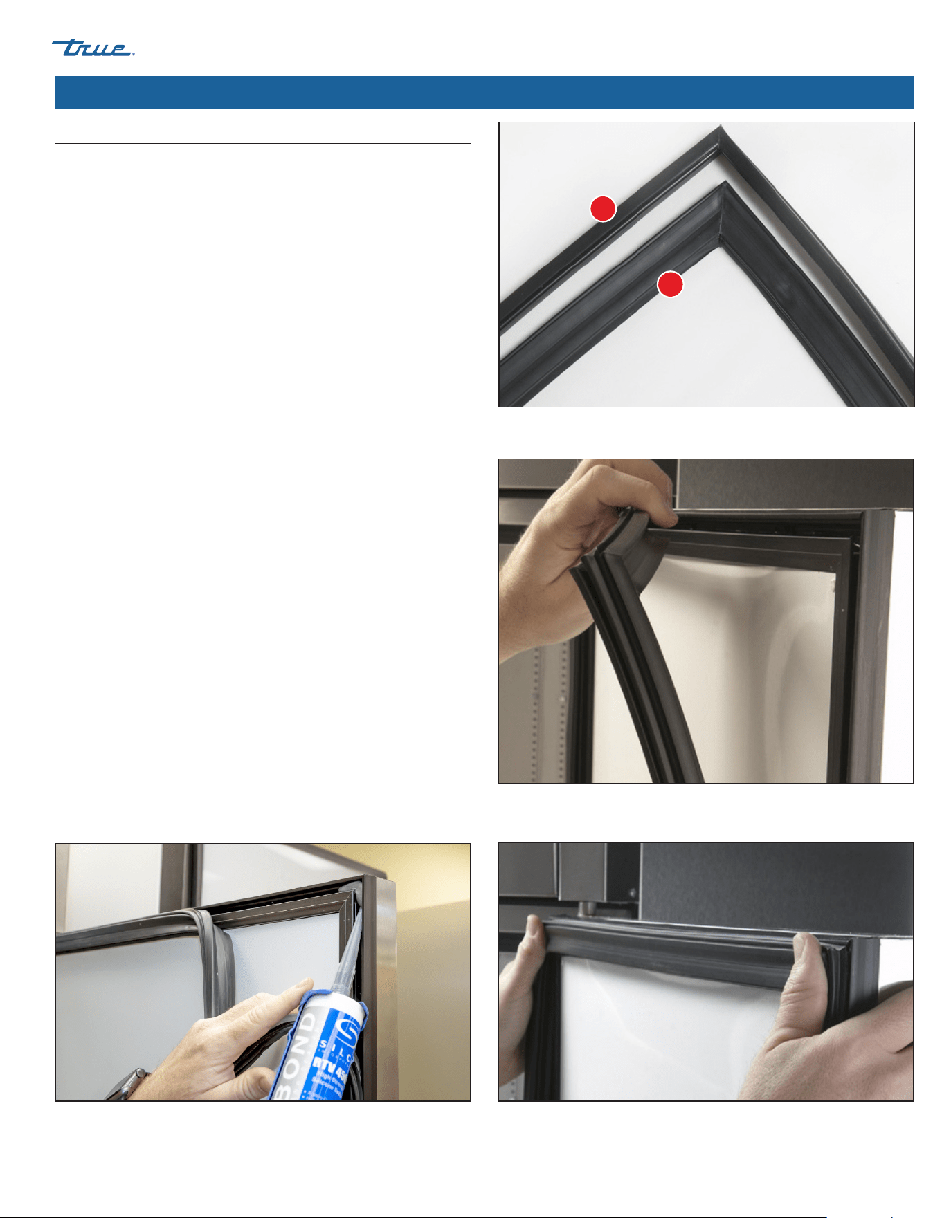
There are two types of door gaskets; narrow and wide gaskets (see
fig 1). The correct gasket for your unit varies by cabinet age and
model. The gaskets are NOT interchangeable.
NOTE: For narrow gaskets, it’s important to remember which
track the gasket was removed from. Normally, the gasket is in
the center track on the top, bottom, and handle sides. On the
hinge side, it's on the inside track.
Procedure
1. From the upper right or left-hand corner, carefully pull
removable gasket away from the door. See fig. 2.
2. Apply silicone to each corner of the door/gasket channel. See
fig. 3.
3. After applying silicone to the corners, push the gaskets back
into their original tracks. Press corners in
NOTE: The silicone will seal any possible air leaks. Excess
silicone should seep out of the track.
4. Clean any excess silicone.
NOTE: Gasket color may vary depending on unit.
Fig. 1. There are two gasket types. A: Narrow gasket; B: Wide gasket.
Fig. 2. Pull the gasket starting at an upper corner.
Fig. 3. Apply silicone to each corner of the gasket channel.
Fig. 4. It is common to see silicone pushed out of track around the gasket. This is
how you know enough silicone was used.
A
B
TBR
|
TDR SERIES www.truemfg.com
TEC_TM_043 | REV. F | EN03/2/2023 Page 36 of 40 P#803294
Cabinet Adjustments, Servicing & Component Replacement (cont.)
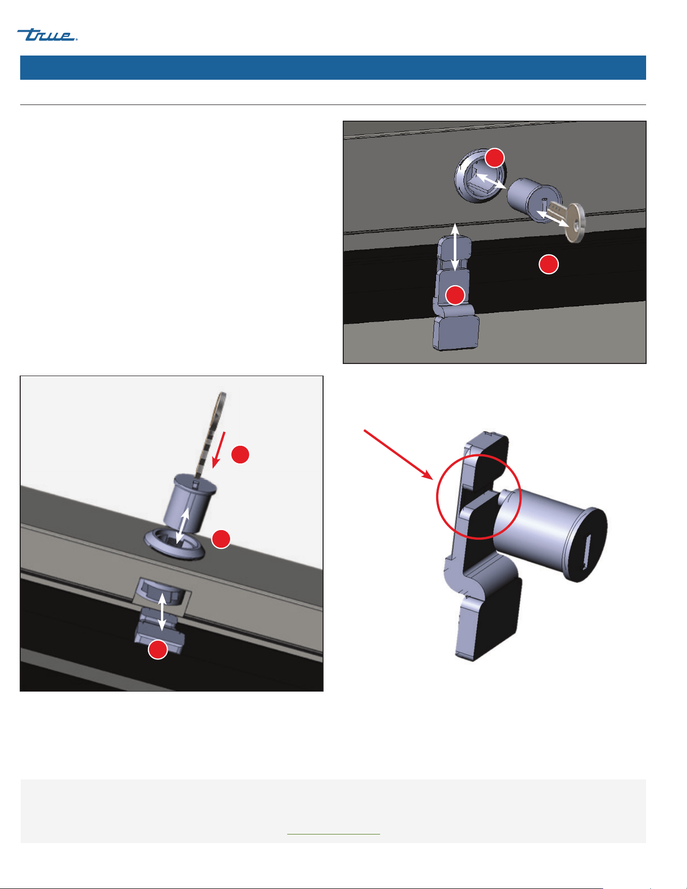
Swing Door Lock & Cam Replacement
The door must be open prior to proceeding.
Procedure: Removing Components
1. Insert the master key (included with the replacement lock kit)
into the lock cylinder.
2. Turn the key and pull to remove the cylinder from the lock
barrel.
3. Slide the lock cam/bar out of the bottom of the lock barrel.
Procedure: Installing Components
1. Slide the lock cam/bar into the bottom of the lock barrel.
2. Push the lock cylinder with master key into the lock barrel.
NOTE: Ensure the pin of the back of the lock cylinder aligns
with the notch in the lock cam/bar. See fig. 3.
Fig. 1. Front view of removing/installing components.
Fig. 2. Bottom view of removing/installing components. Fig. 3. Lock cam/bar notch
1
1
3
3
2
2
FOR MORE INFORMATION
For additional maintenance instruction, please visit the media center at
www.truemfg.com
TBR
|
TDR SERIES
TEC_TM_043 | REV. F | EN
03/2/2023
Page 37 of 40
www.truemfg.com
USA Foodservice & Canada Warranty Statement
To view and download the
Warranty Statements for USA and Canada,
please scan the QR code below.
Warranty Information

TBR
|
TDR SERIES www.truemfg.com
TEC_TM_043 | REV. F | EN03/2/2023 Page 38 of 40 P#803294
NOTES

TBR
|
TDR SERIES
TEC_TM_043 | REV. F | EN
03/2/2023
Page 39 of 40
www.truemfg.com
NOTES

TEC_TM_043 | REV. F | EN03/2/2023 Page 40 of 40 P#803294
BP_191148_07.22
truemfg.com