Installation Instructions for
*M9C80 & *C9C80*
Gas Furnace
CATEGORY I
CATÉGORIE I
These furnaces comply with requirements embod-
ied in the American National Standard / National
Standard of Canada ANSI Z21.47·CSA-2.3 Gas Fired
Central Furnaces.
Installer:
Affix all manuals
adjacent to the unit.
As a professional installer you have an obligation to know
the product better than the customer. This includes all safety
precautions and related items.
Prior to actual installation, thoroughly familiarize yourself
with this Instruction Manual. Pay special attention to all safe-
ty warnings. Often during installation or repair it is possible
to place yourself in a position which is more hazardous than
when the unit is in operation.
Remember, it is your responsibility to install the product
safely and to know it well enough to be able to instruct a
customer in its safe use.
Safety is a matter of common sense...a matter of thinking
before acting. Most dealers have a list of specic good safe-
ty practices...follow them.
The precautions listed in this Installation Manual are intend-
ed as supplemental to existing practices. However, if there is
a direct conict between existing practices and the content of
this manual, the precautions listed herein take precedence.
TABLE OF CONTENTS
Safety Considerations ................................................... 2
Product Application ....................................................... 4
Location Requirements & Considerations ................... 5
Combustion & Ventilation Air Requirements .............. 8
Masonry Chimneys ........................................................ 10
Electrical Connections ............................................... 10
Gas Supply and Piping ................................................... 10
Circulating Air ............................................................... 14
Electrical ....................................................................... 16
Circulating Air & Filters .............................................. 21
Airflow Tables ............................................................... 26
2 Stage Status Codes ................................................... 34
2 Stage Troubleshooting Codes ................................ 36
Wiring Diagram .............................................................. 38
Maintenance ................................................................... 39
Media Air Filter or Electronic Air
Cleaner Removal ...................................................... 39
Before Leaving an Installation ................................... 40
Repair and Replacement Parts ................................... 40
Start Up Checklist ....................................................... 41
Only personnel that have been trained to install, adjust, service
or repair(hereinafter, “service”) the equipment specied in this
manual should service the equipment. The manufacturer will
not be responsible for any injury or property damage arising
from improper service or service procedures. If you service this
unit, you assume responsibility for any injury or property dam-
age which may result. In addition, in jurisdictions that require
one or more licenses to service the equipment specied in this
manual, only licensed personnel should service the equipment.
Improper installation, adjustment, servicing or repair of the
equipment specied in this manual, or attempting to install,
adjust, service or repair the equipment specied in this manual
without proper training may result in product damage, property
damage, personal injury or death.
WARNING
RECOGNIZE THIS SYMBOL
AS A SAFETY PRECAUTION.
*NOTE: Please contact your distributor or our website for the
applicable Specication Sheet referred to in this manual.
IOG-2026A
08/2021
19001 Kermier Rd., Waller, TX 77484
www.goodmanmfg.com • www.amana-hac.com
© 2021 Goodman Manufacturing Company, L.P.
is a registered trademark of Maytag Corporation or its related companies and is used under license.
All rights reserved.
80% HEX
DO NOT LIFT
PRODUCT USING
HEAT EXCHANGER
2
Safety Considerations
Adhere to the following warnings and cautions when install-
ing,adjusting, altering, servicing, or operating the furnace.
To ensure proper installation and operation, thoroughly read
this manual for specics pertaining to the installation and
application of this product.
AVERTISSEMENT
WARNING
FIRE OR EXPLOSION HAZARD
Failure to follow the safety warnings exactly could result
in serious injury, death or property damage.
Never test for gas leaks with an open flame.
Use a commercially available soap solution made
specifically for the detection of leaks to check all
connections. A fire or explosion may result causing
property damage, personal injury or loss of life.
RISQUE D'INCENDIE OU D'EXPLOSION
Si les consignes de sécurité ne sont pas suivies à la lettre,
cela peut entraîner la mort, de graves blessures ou des
dommages matériels.
Ne jamais vérifier la présence de fuites de gaz au moyen
d'une flamme nue. Vérifier tous les raccords en utilisant
une solution savonneuse commerciale conçue
spécialement pour la détection de fuites. Un incendie ou
une explosion risque de se produire, ce qui peut entraîner
la mort, des blessures ou des dommages matériels.
This furnace is manufactured for use with natural gas. It
may be eld converted to operate on L.P. gas by using the
appropriate L.P. conversion kit listed in the PROPANE GAS/
HIGH ALTITUDE INSTALLATIONS section of this manual
Install this furnace only in a location and position as specied
in LOCATION REQUIREMENTS & CONSIDERATIONS
section and INSTALLATION POSITIONS section of this
manual.
Provide adequate combustion and ventilation air to the fur-
nace as specied in COMBUSTION & VENTILATION AIR
REQUIREMENTS section of this manual.
Combustion products must be discharged to the outdoors.
Connect this furnace to an approved vent system only, as
specied in Category 1 Venting section of this manual.
Never test for gas leaks with an open ame. Use a com-
mercially available soap solution made specically for the
detection of leaks to check all connections, as specied in
GAS SUPPLY AND PIPING section of this manual.
Always install a furnace to operate within the furnace’s
intended temperature-rise range with a duct system which
has external static pressure within the allowable range, as
specied on the furnace rating plate and OPERATIONAL
CHECKS section of these instructions.
When furnace duct(s) supply air outside the space contain-
ing the furnace, a return air duct must terminate in the same
space as the supply duct and be sealed to the furnace casing.
A gas-red furnace for installation in a residential garage
must be installed as specied in the LOCATION REQUIRE-
MENTS AND CONSIDERATIONS section of this manual.
This furnace may be used as a construction site heater only
if certain conditions are met. These conditions are listed in
the PRODUCT APPLICATION section of this manual.
WARNING
To prevent personal injury or death due to improper instal-
lation, adjustment, alteration, service, or maintenance, refer
to this manual. For additional assistance or information,
consult a qualified installer, servicer agency or the gas
supplier.
WARNING
If the information in these instructions is not followed
exactly, a fire or explosion may result causing property dam-
age, personal injury or loss of life.
– Do not store or use gasoline or other flammable vapors
and liquid in the vicinity of this or any other appliance.
– What to do if you smell gas:
• Do not try to light any appliance.
• Do not touch any electrical switch; do not use any
phone in your building.
• Immediately call your gas supplier from a neighbor’s
phone. Follow the gas supplier’s instructions. If you can
not reach your gas supplier, call the fire department.
– Installation and service must be performed by a qualified
installer, service agency or the gas supplier.
WARNING
This product contains or produces a chemical or chemicals
which may cause serious illness or death and which are
known to the State of California to cause cancer, birth de-
fects or other reproductive harms.
3
B10259-216
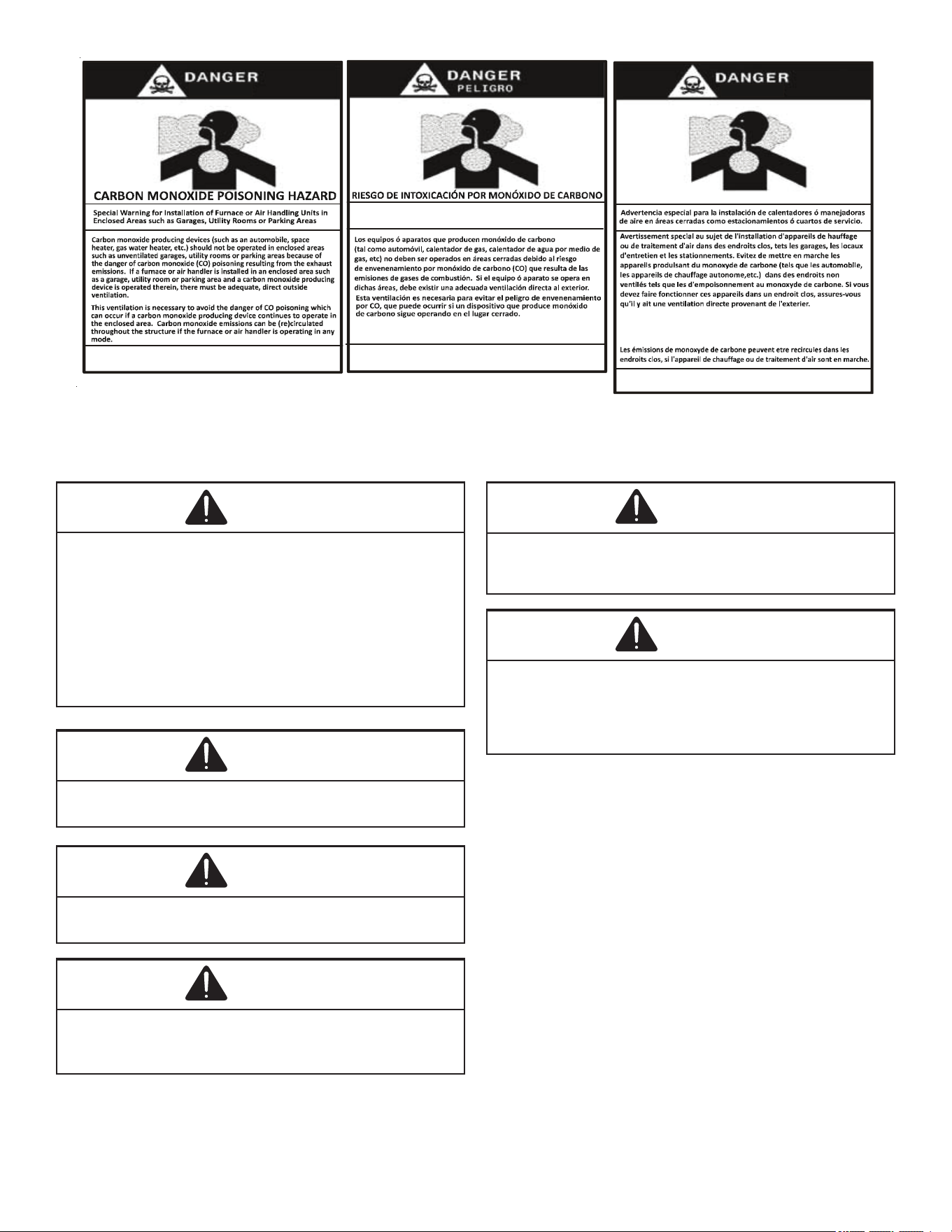
CO can cause serious illness including permanent brain
damage or death.
Advertencia especial para la instalación de calentadores ó manejadoras
de aire en áreas cerradas como estacionamientos ó cuartos de servicio.
B10259-216
El monóxido de carbono puede causar enfermedades severas
como daño cerebral permanente ó muerte.
Las emisiones de monóxido de carbono pueden circular a través
del aparato cuando se opera en cualquier modo.
B10259-216
RISQUE D'EMPOISONNEMENT AU
MONOXYDE DE CARBONE
Le monoxyde de
des
carbone peut causer des maladies graves telles que
dommages permanents au cerveau et meme la mort.
Ce�e ven�la�on est nécessaire pour éviter le danger d'intoxica�on
au CO pouvant survenir si un appareil produisant du monoxyde
de carbone con�nue de fonc�onner au sein de la zone confinée.
WARNING
Heating unit should not be utilized without reasonable rou-
tine, inspection, maintenance and supervision. If the building
in which any such device is routinely inspected, maintained
and monitored. In the event that the building may be exposed
to freezing temperatures and will be vacant, all water-bear-
ing pipes should be drained. The building should be properly
winterized and the water source closed. In the event that
the building may be exposed to freezing temperatures and
will be vacant, any hydronic coil units should be drained as
well and, in such case, alternative heat sources should be
utilized.
WARNING
To prevent possible property damage, personal injury or
death due to electrical shock, the furnace must be located
to protect the electrical components from water.
WARNING
Should overheating occur or the gas supply fail to shut off,
turn off the manual gas shutoff valve external to the fur-
nace before turning off the electrical supply.
WARNING
Possible property damage, personal injury or death due to
fire, explosion, smoke, soot, condensation, electrical shock,
or carbon monoxide may result from improper installation,
repair operation, or maintenance of this product.
WARNING
To prevent personal injury or death due to improper installa-
tion, adjustment, alteration, service or maintenance, refer to
this manual. For additional assistance or information, consult
a qualified installer, servicer agency or the gas supplier.
WARNING
To prevent personal injury or death due to asphyxiation, this
furnace must be Category I vented. Do not vent using Catego-
ry III Venting.
Provisions must be made for venting combustion products
outdoors through a proper venting system. This length of
flue pipe could be a limiting factor in locating the furnace.
Additional Safety Considerations
• This furnace is approved for Category I Venting only.
• Provisions must be made for venting combustion
products outdoors through a proper venting system. The
length of ue pipe could be a limiting factor in locating
the furnace.
Shipping Inspection
All units are securely packed in shipping containers tested
according to International Safe Transit Association speci-
cations. The carton must be checked upon arrival for exter-
nal damage. If damage is found, a request for inspection by
carrier’s agent must be made in writing immediately.
The furnace must be carefully inspected on arrival for damage
and bolts or screws which may have come loose in transit.
In the event of damage the consignee should:
1. Make a notation on delivery receipt of any visible
damage to shipment or container.
2. Notify carrier promptly and request an inspection.

4
3. With concealed damage, carrier must be notied as soon
as possible - preferably within ve days.
4. File the claim with the following support documents
within a nine month statute of limitations.
• Original or certied copy of the Bill of Lading, or
indemnity bond.
• Original paid freight bill or indemnity in lieu thereof.
• Original or certied copy of the invoice, showing trade
and other discounts or reductions.
• Copy of the inspection report issued by carrier’s
representative at the time damage is reported to carrier.
The carrier is responsible for making prompt inspection of
damage and for a thorough investigation of each claim. The
distributor or manufacturer will not accept claims from deal-
ers for transportation damage.
Keep this literature in a safe place for future refer ence.
Electrostatic Discharge (ESD) Precautions
NOTE: Discharge body’s static electricity before touching
unit. An electrostatic discharge can adversely aect electri-
cal components.
Use the following precautions during furnace installation and
servicing to protect the integrated control module from dam-
age. By putting the furnace, the control, and the person at
the same electrostatic potential, these steps will help avoid
exposing the integrated control module to electrostatic dis-
charge. This procedure is applicable to both installed and
non-installed (ungrounded) furnaces.
1. Disconnect all power to the furnace. Do not touch the
integrated control module or any wire connected to the
control prior to discharging your body’s electrostatic
charge to ground.
2. Firmly touch a clean, unpainted, metal surface of the
furnaces near the control. Any tools held in a person’s
hand during grounding will be discharged.
3. Service integrated control module or connecting wiring
following the discharge process in step 2. Use caution
not to recharge your body with static electricity; (i.e., do
not move or shue your feet, do not touch ungrounded
objects, etc.). If you come in contact with an ungrounded
object, repeat step 2 before touching control or wires.
4. Discharge your body to ground before removing a new
control from its container. Follow steps 1 through 3 if
installing the control on a furnace. Return any old or
new controls to their containers before touching any
ungrounded object.
To The Installer
Before installing this unit, please read this manual thoroughly
to familiarize yourself with specic items which must be ad-
hered to, including but not limited to: unit maximum external
static pressure, gas pressures, BTU input rating, proper elec-
trical connections, circulating air temperature rise, minimum
or maximum CFM, and motor speed connections, and vent-
ing. These furnaces are designed for Category I venting only.
WARNING
To prevent property damage, personal injury, or death due to
fire, do not install this furnace in a mobile home, trailer, or
recreational vehicle.
Product Application
This furnace is primarily designed for residential home-heat-
ing applications. It is NOT designed or certied for use in
mobile homes, trailers or recreational vehicles. Neither is it
designed or certied for outdoor applications. The furnace
must be installed indoors (i.e., attic space, crawl space, or
garage area provided the garage area is enclosed with an
operating door).
This furnace can be used in the following non-industrial
commercial applications:
Schools, Oce Buildings, Churches, Retail Stores,
Nursing Homes, Hotels/Motels, Common or Oce Areas
In such applications, the furnace must be installed with the
following stipulations:
• It must be installed per the installation instructions
provided and per local and national codes.
• It must be installed indoors in a building constructed
on site.
• It must be part of a ducted system and not used in a free
air delivery application.
• It must not be used as a “make-up” air unit.
• All other warranty exclusions and restrictions apply.
This furnace may be used as a construction site heater
ONLY if all of the following conditions are met:
• The vent system is permanently installed per these
installation instructions.
• A room thermostat is used to control the furnace. Fixed
jumpers that provide continuous heating CANNOT be
used and can cause long term equipment damage.
Bi-metal thermostats, or any thermostat aected by
vibration must not be used during construction.
• Return air ducts are provided and sealed to the furnace.
• A return air temperature range between 60ºF (16ºC) and
80ºF (27ºC) is maintained.
• Air lters are installed in the system and replaced daily
during construction and upon completion of construction.
• The input rate and temperature rise are set per the
furnace rating plate.
• 100% outside air must be used for combustion during
construction. Temporary ducting may be used to supply
outside air to the furnace for combustion – do not connect
this duct directly to the furnace. Size this duct according
to NFPA 54/ANSI Z223.1 section for Combustion and
Ventilation Air.
5
• The furnace heat exchanger, components, duct system,
air lters and evaporator coils are thoroughly cleaned
following final construction clean up by a qualified
person.
• All furnace operating conditions (including ignition,
input rate, temperature rise and venting) are veried
by a qualied person according to these installation
instructions.
• Furnace doors must be in place on the furnace while the
furnace is operating in any mode.
• Damage or repairs due to failure to comply with these
requirements are not covered under the warranty.
NOTE: The Commonwealth of Massachusetts requires that
the following additional requirements must also be met:
• Gas furnaces must be installed by a licensed plumber
or gas tter.
• A T-handle gas cock must be used.
• If the unit is to be installed in an attic, the passageway to
and the service area around the unit must have ooring.
WARNING
To prevent property damage, personal injury, or death due to
fire, do not install this furnace in a mobile home, trailer, or
recreational vehicle.
To ensure proper furnace operation, install, operate and
maintain the furnace in accordance with these installation
and operation instructions, all local building codes and
ordinances. In their absence, follow the latest edition of the
National Fuel Gas Code (NFPA 54/ANSI Z223.1) and/or local
plumbing or waste water codes, and other applicable codes.
A copy of the National Fuel Gas Code (NFPA 54/ANSI Z223.1)
can be obtained from any of the following:
American National Standards Institute
25 West 43rd Street, 4th Floor
New York, NY 10036
National Fire Protection Association
1 Batterymarch Park
Quincy, MA 02169-7471
CSA International
8501 East Pleasant Valley
Independence, OH 44131
The rated heating capacity of the furnace should be greater
than or equal to the total heat loss of the area to be heated.
The total heat loss should be calculated by an approved
method or in accordance with “ASHRAE Guide” or “Manual
J-Load Calculations” published by the Air Conditioning Con-
tractors of America.
In the USA, this furnace MUST be installed in accordance
with the latest edition of the ANSI Z223.1 booklet entitled
“National Fuel Gas Code” (NFPA 54), and the requirements
or codes of the local utility or other authority having jurisdic-
tion. Additional helpful publications available from the NFPA
are, NFPA 90A - Installation of Air Conditioning and Venti-
lating System and NFPA 90B - Warm Air Heating and Air
Conditioning System.
All venting shall be in accordance with the National Fuel Gas
Code, ANSI Z223.1, or applicable local building and/or air
conditioning codes.
NOTE: Furnaces with NOx screens meet the California NOx
emission standards and California seasonal eciency stan-
dards. ANNUAL inspections of the furnace and its vent sys-
tem is strongly recommended.
Location Requirements and Considerations
Your unit model type determines which installation proce-
dures must be used. For *M9C80 models, you must follow
instructions for Horizontal Left, Horizontal Right or Upow
installations only. These furnaces are not approved for Down-
ow installations.
*C9C80 models may be installed in the Downow position as
well as Horizontal Left & Horizontal Right positions.
WARNING
To prevent possible equipment damage, property damage,
personal injury, or death, the following bullet points must
be observed when installing this unit.
Follow the instructions listed below when selecting a furnace
location. Refer also to the guidelines provided in the Com-
bustion and Ventilation Air Requirements.
• Centrally locate the furnace with respect to the proposed
or existing air distribution system.
• Ensure the temperature of the return air entering the
furnace is between 55°F and 100°F when the furnace
is heating.
• Provisions must be made for venting combustion products
outdoors through a proper venting system. The length of
ue pipe could be a limiting factor in locating the furnace.
• Ensure adequate combustion air is available for
the furnace. Improper or insucient combustion air
can expose building occupants to gas combustion
products that could include carbon monoxide. Refer to
Combustion and Ventilation Air Requirements section.
• The furnace must be level. If the furnace is to be set
on a oor that may become wet or damp at times,
the furnace should be supported above the oor on a
concrete base sized approximately 1-½” larger than the
base of the furnace.
• Ensure upow or horizontal furnaces are not installed
directly on carpeting, or any other combustible material.
The only combustible material allowed is wood.
6
• Exposure to contaminated combustion air will result in
safety and performance-related problems. Do not install
the furnace where the combustion air is exposed to the
following substances:
chlorinated waxes or cleaners
chlorine-based swimming pool chemicals
water softening chemicals
deicing salts or chemicals
carbon tetrachloride
halogen type refrigerants
cleaning solutions (such as perchloroethylene)
printing inks
paint removers
varnishes
hydrochloric acid
cements and glues
antistatic fabric softeners for clothes dryers
and masonry acid washing materials
• If the furnace is used in connection with a cooling unit,
install the furnace upstream or in parallel with the cooling
unit coil. Premature heat exchanger failure will result if
the cooling unit coil is placed ahead of the furnace.
• For vertical applications, the minimum cooling coil
width shall not be less than furnace width minus 1”.
Additionally, a coil installed above an upow furnace or
under a counterow furnace may be the same width as
the furnace or may be one size larger than the furnace.
Example: a “C” width coil may be installed with a “B”
width furnace.
• For upow applications, the front of the coil and furnace
must face the same direction.
• If the furnace is installed in a residential garage, position
the furnace so that the burners and ignition source are
located not less than 18 inches (457 mm) above the oor.
Protect the furnace from physical damage by vehicles.
• If the furnace is installed horizontally, the furnace access
doors must be vertical so that the burners re horizontally
into the heat exchanger. Do not install the unit with the
access doors on the “up/top” or “down/bottom” side of
the furnace.
• Do not connect this furnace to a chimney ue that serves
a separate appliance designed to burn solid fuel.
• Counterow installation over a noncombustible oor.
Before setting the furnace over the plenum opening,
ensure the surface around the opening is smooth and
level. A tight seal should be made between the furnace
base and floor by using a silicon rubber caulking
compound or cement grout.
• Counterow installation over a combustible oor. If
installation over a combustible oor becomes necessary,
use an accessory subbase (see Specication Sheet
applicable to your model for details). A special accessory
subbase must be used for upright counterow unit
installations over any combustible material including
wood. Follow the instructions with the subbase for proper
installations.
• Do not install the furnace directly on carpeting, tile, or
other combustible material other than wood ooring.
(NOTE: The subbase will not be required if an air
conditioning coil is installed between the supply air
opening on the furnace and the oor. The air conditioning
coil must be downstream from the heat exchanger of
the furnace.
Top - 1"
Side
Clearance - 1"
Back - 0"
Front Clearance - 3"
Vent Pipe Clearance to Combustibles-
6" using Single Wall Connector or 1"
using B-1 vent.
Figure 1
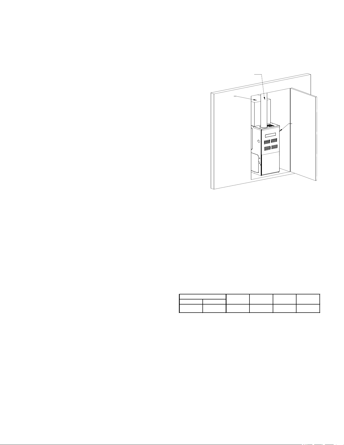
• Adequate combustion/ventilation air must be supplied
to the closet.
• Furnace must be completely sealed to oor or base.
Combustion/ventilation air supply pipes must terminate
12” from top of closet and 12” from oor of closet. DO
NOT remove solid base plate for side return.
• Return air ducts must be completely sealed to the
furnace and terminate outside the enclosure surfaces.
Clearances and Accessibility
Unobstructed front clearance of 24” for servicing is
recommended.
TOP
B1-VENT SINGLE
(PLENUM)
1" 6" 1" 3" 0" 1"
VENT
SIDES
FRONT
BACK
Top clearance for horizontal conguration - 1”
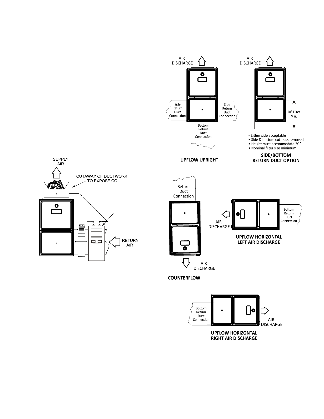
Installation Positions
*M9C80 model furnaces may be installed vertically (upow)
or horizontally with left or right side down. *C9C80 model
furnaces may be installed vertically (downow) or horizon-
tally with left or right side down. Do not install this furnace
on its back. For vertically installed upow furnaces, return
air ductwork may be attached to the side panel(s) and/or
basepan. For horizontally installed upow furnaces, return
air ductwork must be attached to the basepan. For coun-
terow furnaces, return ductwork must be attached to the
blower compartment end of the furnace.
7
NOTE: Ductwork must never be attached to the back of the
furnace.
Horizontal Installation
Line contact to framing is permitted when installed in the hor-
izontal conguration. Line contact is dened as the portion
of the cabinet that is formed by the intersection of the top
and side. ACCESSIBILITY CLEARANCE, WHERE GREAT-
ER, SHOULD TAKE PRECEDENCE OVER MINIMUM FIRE
PROTECTION CLEARANCE. A gas-red furnace for instal-
lation in a residential garage must be installed so that the
ignition source and burners are located not less than eigh-
teen inches (18”) above the oor and is protected or located
to prevent physical damage by vehicles. A gas furnace must
not be installed directly on carpeting, tile, or other combusti-
ble materials other than wood ooring.
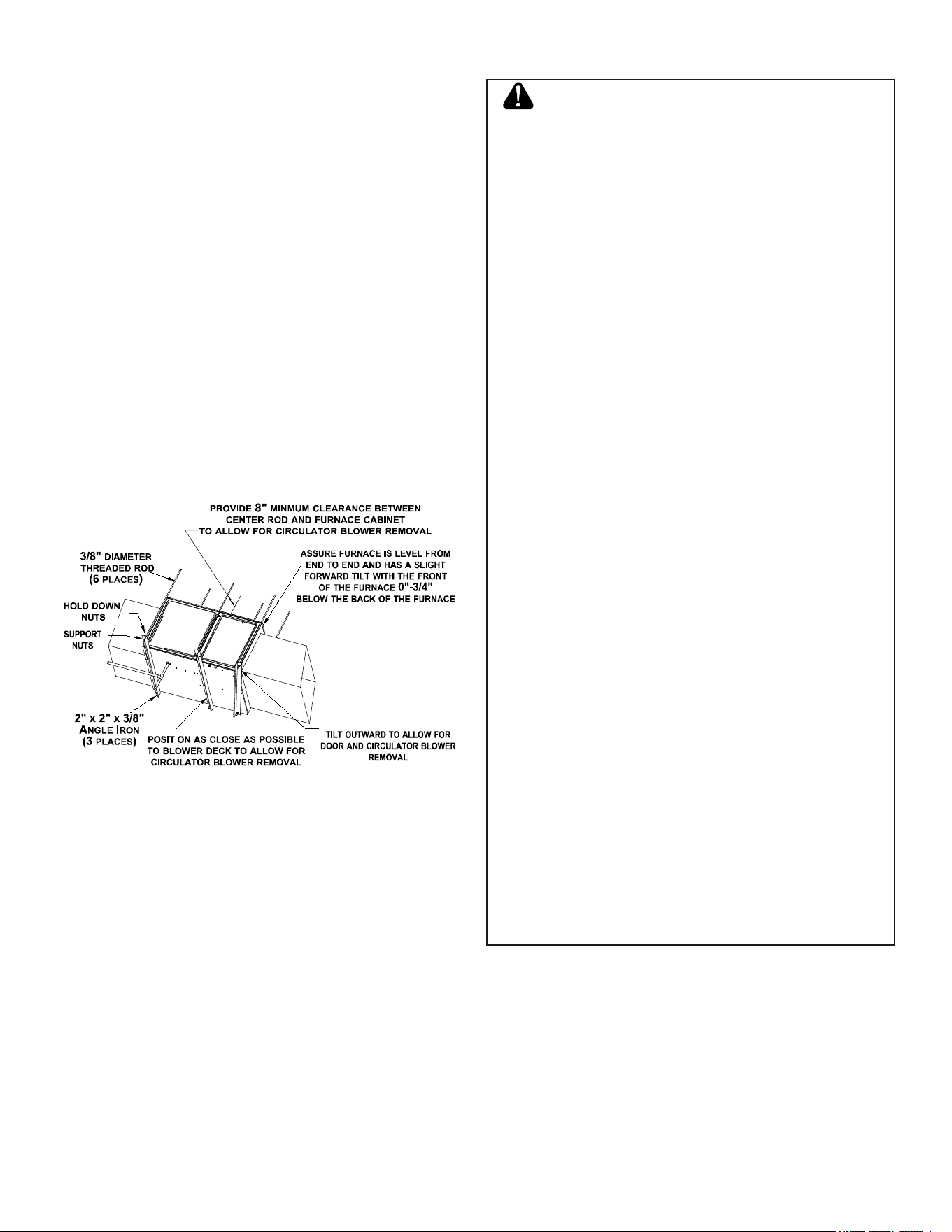
Furnace Suspension
If suspending the furnace from rafters or joist, use 3/8”
threaded rod and 2”x2”x3/8” angle iron as shown below. The
length of rod will depend on the application and the clear-
ances necessary.
Suspended Furnace
Figure 2
Existing Furnace Removal
WARNING
CARBON MONOXIDE POISONING HAZARD
Failure to follow the steps outlined below for each
appliance connected to the venting system being placed
into operation could result in carbon monoxide poisoning or
death.
The following steps shall be followed for each appliance
connected to the venting system being placed into
operation, while all other appliances connected to the
venting system are not in operation:
1) Seal any unused openings in the venting system.
2) Inspect the venting system for proper size and horizontal
pitch, as required in the National Fuel Gas Code, ANSI
Z223.1/NFPA 54 or the Natural Gas and Propane
Installation Code, CSA B149.1 and these instructions.
Determine that there is no blockage or restriction,
leakage, corrosion and other deficiencies which could
cause an unsafe condition.
3) As far as practical, close all building doors and windows
and all doors between the space in which the
appliance(s) connected to the venting system are located
and other spaces of the building.
4) Close fireplace dampers.
5) Turn on clothes dryers and any appliance not connected
to the venting system. Turn on any exhaust fans, such as
range hoods and bathroom exhausts, so they are
operating at maximum speed. Do not operate a summer
exhaust fan.
6) Follow the lighting instructions. Place the appliance being
inspected into operation. Adjust the thermostat so
appliance is operating continuously.
7) Test for spillage from draft hood equipped appliances at
the draft hood relief opening after 5 minutes of main
burner operation. Use the flame of a match or candle.
8) If improper venting is observed during any of the above
tests, the venting system must be corrected in
accordance with the National Fuel Gas Code, ANSI
Z223.1/NFPA 54 and/or Natural Gas and Propane
Installation Code, CSA B149.1.
9) After it has been determined that each appliance
connected to the venting system properly vents when
tested as outlined above, return doors, windows, exhaust
fans, fireplace dampers and any other gas-fired burning
appliance to their previous conditions of use.
8
RISQUE D'INTOXICATION AU MONOXYDE DE CARBONE
Si les étapes décrites ci-dessous ne sont pas suivies pour
chacun des appareils raccordés au système de ventilation
au moment de sa mise en marche, cela peut entraîner une
intoxication au monoxyde de carbone ou la mort. Les
étapes suivantes doivent être suivies pour chacun des
appareils raccordés au système de ventilation au moment
de sa mise en marche, alors que tous les autres appareils
raccordés au système de ventilation ne sont pas en marche:
1) Sceller toutes les ouvertures inutilisées du système
de ventilation.
2) Inspecter le système de ventilation afin de vérifier si la
taille et l'inclinaison par rapport à l'horizontale sont
conformes aux exigences du National Fuel Gas Code,
ANSI Z223.1/NFPA 54 ou du Code d'installation du gaz
naturel et du propane, CSA B149.1 et à ces instructions.
Vérifier qu'il n'y a pas d'obstruction ou de restriction, de
fuite, de corrosion et d'autres problèmes qui pourraient
entraîner une situation dangereuse.
3) Si possible, fermer toutes les portes et fenêtres du
bâtiment ainsi que toutes les portes séparant l'endroit
où se trouvent les appareils raccordés au système de
ventilation et les autres zones du bâtiment.
4) Fermer le registre des foyers.
5) Mettre les sécheuses en marche ainsi que tous les
autres appareils qui ne sont pas raccordés au système de
ventilation. Mettre en marche tous les ventilateurs de
tirage, comme celui des hottes de cuisine et des salles de
bains, et les régler à la puissance maximale. Ne pas
mettre en marche les ventilateurs d'été.
6) Suivre les instructions d'allumage. Mettre en marche
l'appareil soumis à l'inspection. Régler le thermostat
de manière à ce que l'appareil fonctionne en continu.
7) Vérifier la présence de fuite au niveau de l'ouverture
du coupe-tirage des appareils qui en sont dotés après 5
minutes de fonctionnement du brûleur principal. Utiliser
la flamme d'une allumette ou d'une bougie.
8) Si un problème de ventilation est observé pendant
l'un des essais décrits ci-dessus, des correctifs doivent
être apportés au système de ventilation conformément
au National Fuel Gas Code, ANSI Z223.1/NFPA 54 et (ou)
au Code d'installation du gaz naturel et du propane, CSA
B149.1.
9) Une fois qu'il a été déterminé que chaque appareil
raccordé au système de ventilation fonctionne
correctement au moyen des essais décrits ci-dessus,
les portes, les fenêtres, les ventilateurs, les registres
de foyer et tous les autres appareils de combustion
alimentés au gaz doivent être remis dans leur état
initial.
AVERTISSEMENT
Corrections must be in accordance with the latest edition of
the National Fuel Gas Code NFPA 54/ANSI Z223.1 and/or
CAN/CSA B149 Installation Codes.
If resizing is required on any portion of the venting system,
use the appropriate table in the latest edition of the National
Fuel Gas Code ANSI Z223.1.
Thermostat Location
In an area having good air circulation, locate the thermostat
about ve feet high on a vibration-free inside wall. Do not
install the thermostat where it may be inuenced by any of
the following:
• Drafts, or dead spots behind doors, in corners, or under
cabinets.
• Hot or cold air from registers.
• Radiant heat from the sun.
• Light xtures or other appliances.
• Radiant heat from a replace.
• Concealed hot or cold water pipes, or chimneys.
• Unconditioned areas behind the thermostat, such as
an outside wall.
Consult the instructions packaged with the thermostat for
mounting instructions and further precautions.
Combustion and Ventilation
Air Requirements
WARNING
To avoid property damage, personal injury or death, suffi-
cient fresh air for proper combustion and ventilation of
flue gas must be supplied. Most homes require outside air be
supplied into the furnace area.
Improved construction and additional insulation in build-
ings have reduced heat loss by reducing air inltration and
escape around doors and windows. These changes have
helped in reducing heating/cooling costs but have created
a problem supplying combustion and ventilation air for gas
red and other fuel burning appliances. Appliances that pull
air out of the house (clothes dryers, exhaust fans, replaces,
etc.) increase the problem by starving appliances for air.
House depressurization can cause back drafting or improp-
er combustion of gas-red appliances, thereby exposing
building occupants to gas combustion products that could
include carbon monoxide.
If this furnace is to be installed in the same space with other
gas appliances, such as a water heater, ensure there is an
adequate supply of combustion and ventilation air for all ap-
pliances. Refer to the latest edition of the National Fuel Gas
Code NFPA 54/ANSI Z223.1 or CAN/CSA B149 Installation
Codes or applicable provisions of the local building codes
for determining the combustion air requirements for the ap-
pliances.
This furnace must use indoor air for combustion. It cannot be
installed as a direct vent (i.e., sealed com bustion) furnace.
9
Most homes will require outside air be supplied to the fur-
nace area by means of ventilation grilles or ducts connecting
directly to the outdoors or spaces open to the outdoors such
as attics or crawl spaces.
Category I Venting (Vertical Venting)
WARNING
To prevent possible personal injury or death due to asphyx-
iation, this furnace must be Category I vented. Do not vent
using Category III venting.
Category I Venting is venting at a non-positive pressure. A
furnace vented as Category I is considered a fan-assisted
appliance and the vent system does not have to be “gas
tight”. NOTE: Gas furnaces with induced draft blowers draw
products of combustion through a heat exchanger allowing,
in some instances, common venting with natural draft appli-
ances (i.e. water heaters). All installations must be vented
in accordance with National Fuel Gas Code NFPA 54/ANSI
Z223.1 - latest edition.
NOTE: The vertical height of the Category I venting system
must be at least as great as the horizontal length of the vent-
ing system.
WARNING
To prevent possible personal injury or death due to asphyx-
iation, common venting with other manufacturer’s induced
draft appliances is not allowed.
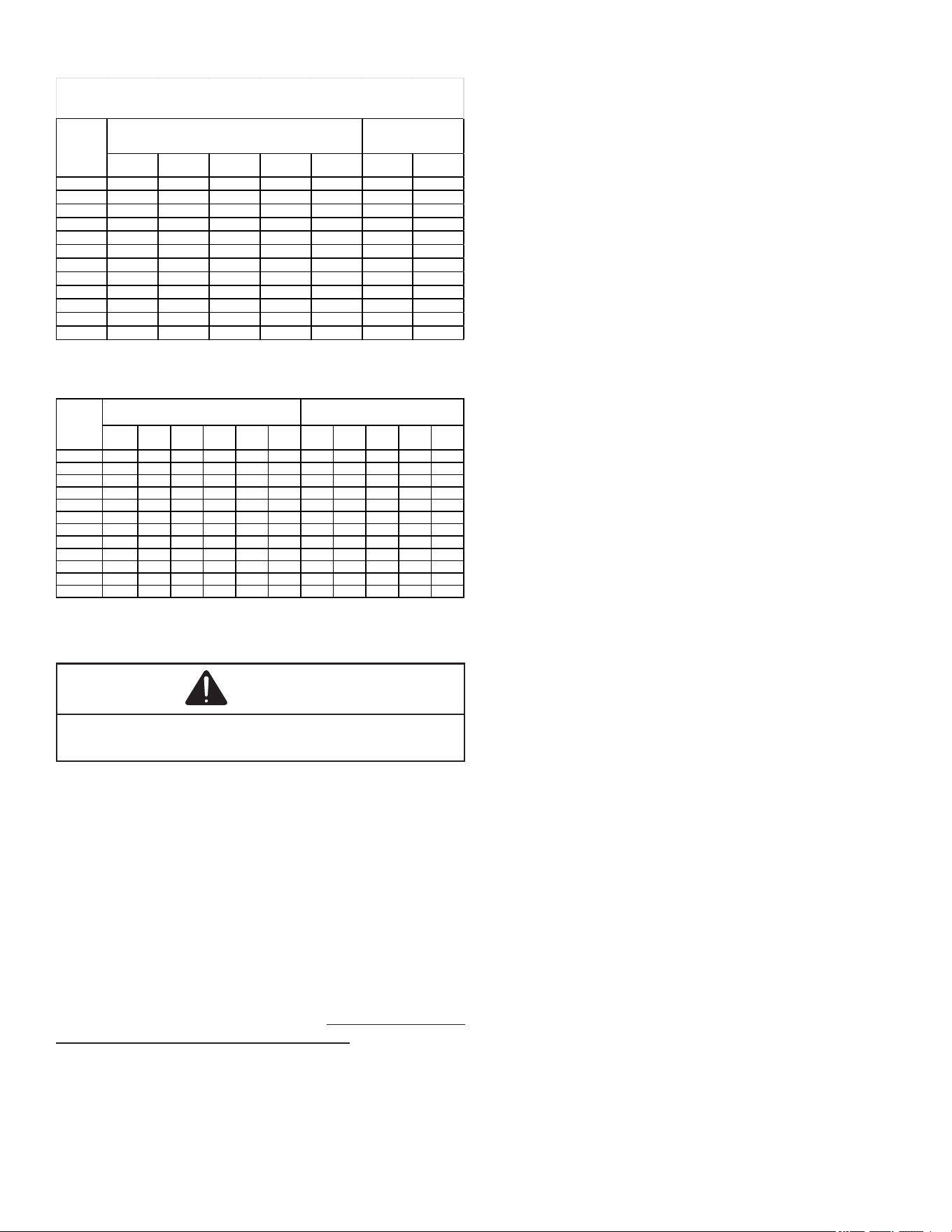
The minimum vent diameter for the Category I venting sys-
tem is as shown:
UPFLOW
COUNTERFLOW
060
4 inch
4 inch
080
4 inch
4 inch
100
5 inch
4 inch
MINIMUM VENT
MODEL
Under some conditions, larger vents than those shown
above may be required or allowed. When an existing fur-
nace is removed from a venting system serving other appli-
ances, the venting system may be too large to properly vent
the remaining attached appliances.
Furnaces are shipped with the induced draft blower dis-
charging from the top of the furnace. (“Top” is as viewed for
an upow installation.) The induced draft blower on *M9C80
models can be rotated 90 degrees for Category I venting.
For furnaces installed vertically or horizontally, a four-inch
single wall pipe can be used to extend the induced draft
blower outlet ½” beyond the furnace cabinet. On *M9C80
furnaces installed upow or horizontally with left side down,
the draft inducer may be rotated to discharge from the right
side of the cabinet. When rotating the inducer a chimney
transition bottom kit (part # 4053501S) is needed for prop-
er alignment of the inducer outlet and the vent exit hole in
the side of the cabinet. The inducer may NOT be rotated on
*C9C80 model furnaces regardless of installation position.
THIS PRODUCT IS NOT DESIGNED FOR COUNTER-
CLOCKWISE INDUCED DRAFT BLOWER ROTATION.
Vent the furnace in accordance with the National Fuel Gas
Code NFPA 54/ANSI Z223.1 - latest edition.
Venting
THIS FURNACE IS NOT DESIGN CERTIFIED TO BE HOR-
IZONTALLY VENTED.
To rotate the induced draft blower clockwise, you will need
to purchase one (4053501S) chimney transition bottom kit.
1. Disconnect electrical power from the furnace.
2. Disconnect the induced draft blower power leads, ue
pipe, and pressure switch tubing.
3. Remove the round cutout from the right side of the
wrapper.
4. Remove and save the four screws that fasten the
induced draft blower to the ue collector box.
5. Remove and save the three screws that hold the
chimney assembly to the induced draft blower.
6. Remove and save the four screws that fasten the
chimney top to the chimney bottom.
7. Remove the chimney transition bottom from the
transition bottom kit.
8. Install the chimney top with the four screws retained from
step 6 onto the new chimney transition bottom from the
transition bottom kit.
9. Install chimney assembly with the three screws retained
from step 5 onto the induced draft blower.
10. Reinstall the induced draft blower rotating it 90 degrees
clockwise from the original upow conguration using the
four screws retained in step 3. Ensure the gasket located
between the induced draft blower and the collector box
is rotated accordingly.
11. Reconnect the induced draft blower power leads. NOTE:
If the wires are not long enough, pull extra wire from the
wire bundle in the blower compartment.
12. Reconnect the ue pipe, and the pressure switch tubing.
Ensure that all wires and the pressure switch tubing is at
least one inch from the ue pipe, or any other hot surface.
13. Restore power to furnace.
Counterow units are shipped with the induced draft blow-
er discharging from the top of the furnace. (“Top” as viewed
for a counterow installation.)
Vent the furnace in accordance with the National Fuel Gas
Code NFPA54/ANSI Z223.1 - latest edition.
WARNING
Never allow the products of combustion, including carbon
monoxide, to enter the return ductwork or circulation air
supply.
10
Masonry Chimneys
WARNING
Possibility of property damage, personal injury or death
damaging condensation can occur inside masonry chimneys
when a single fan-assisted Category I appliance (80% AFUE
furnace) is vented without adequate dilution air. Do not
connect an 80% furnace to a masonry chimney unless the fur-
nace is common vented with a draft hood equipped appliance
or the chimney is lined with a metal liner or Type B metal
vent. All installations using masonry chimneys must be sized
in accordance with appropriate venting tables. If an 80% fur-
naces common vented with a draft hood equipped appliance,
the potential for condensation damage may still exist with
extremely cold conditions, long vent connectors, exterior
chimneys, or any combination of these conditions. The risk
of condensation damages is best avoided by using masonry
chimney as a pathway for properly sized metal liner or Type B
metal vent.
Masonry Chimney Terminations
A masonry chimney used as a vent for gas red equipment
must extend at least three feet above the highest point
where it passes through the roof. It must extend at least two
feet higher than any portion of a building within a horizontal
distance of 10 feet. In addition, the chimney must terminate
at least three feet above any forced air inlet located within
10 feet. The chimney must extend at least ve above the
highest connected equipment draft hood outlet or ue collar.
Electrical Connections
WARNING
HIGH VOLTAGE!
To avoid the risk of electrical shock, wiring to
the unit must be polarized and grounded.
CAUTION
Label all wires prior to disconnection when servicing
controls. Wiring errors can cause improper and dangerous
operation. Verify proper operation after servicing.
WARNING
HIGH VOLTAGE!
To avoid risk of injury, electrical shock or death,
the furnace must be electrically grounded in
accordance with local codes or in their absence,
with the latest edition of the National Electric
Code.
WARNING
Edges of sheet metal holes may be sharp. Use gloves as a
precaution when removing hole plugs.
Wiring Harness
The wiring harness is an integral part of this furnace. Field
alteration to comply with electrical codes should not be re-
quired. Wires are color coded for identication purposes.
Refer to the wiring diagram for wire routings. If any of the
original wire as supplied with the furnace must be replaced,
it must be replaced with wiring material having a tempera-
ture rating of at least 105°C. Any replacement wiring must
be a copper conductor.
115 Volt Line Connections
Before proceeding with electrical connections, ensure that
the supply voltage, frequency, and phase correspond to that
specied on the unit rating plate. Power supply to the fur-
nace must be NEC Class 1, and must comply with all appli-
cable codes. The furnace must be electrically grounded in
accordance with local codes or, in their absence, with the
latest edition of The National Electric Code, ANSI NFPA 70
and/or The Canadian Electric Code CSA C22.1.
Use a separate fused branch electrical circuit containing
properly sized wire, and fuse or circuit breaker. The fuse or
circuit breaker must be sized in accordance with the max-
imum overcurrent protection specied on the unit rating
plate. An electrical disconnect must be provided at the fur-
nace location.
Connect hot, neutral, and ground wires as shown in the wir-
ing diagram located on the unit’s blower door. Metal conduit
is not considered a substitute for an actual ground wire to
the unit.
Line polarity must be observed when making eld connec-
tions. Line voltage connections can be made through either
the right or left side panel. The furnace is shipped congured
for a right side electrical connection with the junction box lo-
cated inside the burner compartment (blower compartment
for downows). To make electrical connections through the
opposite side of the furnace, the junction box must be relo-
cated to the other side of the burner (or blower) compart-
ment prior to making electrical connections. To relocate the
junction box, follow the steps shown below.
NOTE: Wire routing must not to interfere with circulator
blower operation, lter removal, or routine maintenance.
Junction Box Relocation
WARNING
Edges of sheet metal holes may be sharp. Use gloves as a
precaution when removing hole plugs.
WARNING
To prevent personal injury or death due to electric shock,
disconnect electrical power before installing or servicing
this unit.
11
1. Remove both doors from the furnace.
2. Remove and save the screws holding the junc tion box
to the right side of the furnace.
3. Attach the junction box to the left side of the fur nace,
using the screws removed in step 2.
4. Check the location of the wiring. Conrm that it will not be
damaged by heat from the burners or by the rotation of
the fan. Also conrm that wiring location will not interfere
with l ter removal or other maintenance.
IMPORTANT NOTE: To avoid possible equipment malfunc-
tion, route the low voltage wires to avoid interference with
lter removal or other maintenance.
WARNING
HIGH VOLTAGE!
To avoid risk of injury, electrical shock or death,
the furnace must be electrically grounded in
accordance with local codes or in their absence,
with the latest edition of the National Electric
Code.
To ensure proper unit grounding, the ground wire should run
from the furnace ground screw located inside the furnace
junction box all the way back to the electrical panel. NOTE:
Do not use gas piping as an electrical ground. To conrm
proper unit grounding, turn o the electrical power and per-
form the following check.
1. Measure resistance between the neutral (white)
connection and one of the burners.
2. Resistance should measure 10 ohms or less.
This furnace is equipped with a blower door interlock switch
which interrupts unit voltage when the blower door is opened
for servicing. Do not defeat this switch.
Gas Supply and Piping
The furnace rating plate includes the approved furnace gas
input rating and gas types. The furnace must be equipped to
operate on the type of gas applied. This includes any con-
version kits required for alternate fuels and/or high altitude.
CAUTION
To prevent unreliable operation or equipment damage, the
inlet gas supply pressure must be as specified on the unit
rating plate with all other household gas fired appliances
operating.
Inlet gas supply pressures must be maintained within the
ranges specied in the following table. The supply pressure
must be constant and available with all other household gas
red appliances operating. The minimum gas supply pres-
sure must be maintained to prevent unreliable ignition. The
maximum must not be exceeded to prevent unit overring.
NOTE: Do not remove the gas valve inlet plug before the
gas line is installed. Replace if water or debris has been
introduced.
Natural Gas Minimum: 4.5" w.c. Maximum: 10.0" w.c.
Propane Gas Minimum: 11.0" w.c. Maximum: 13.0" w.c.
INLET GAS SUPPLY PRESSURE
NOTE: Adjusting the minimum supply pressure below the
limits in the above table could lead to unreliable ignition.
Gas input to the burners must not exceed the rated input
shown on the rating plate. Overring of the fur nace can re-
sult in premature heat exchanger failure. Gas pressures in
excess of 13 inch es water column can also cause perma-
nent damage to the gas valve.
At all altitudes, the manifold pressure must be within 0.3
inches w.c. of that listed in the Specication Sheet applica-
ble to your model for the fuel used. At all altitudes and with
either fuel, the air tempera ture rise must be within the range
listed on the furnace nameplate. Should this appliance be
converted to LP, refer to the instructions included in the fac-
tory authorized LP conversion kit.
High Altitude Derate
High altitude installations may require both a pressure
switch and an orice change. These changes are necessary
to compensate for the natural reduction in the density of
both the gas fuel and the combustion air at higher altitude.
Clearance in accordance with local installation codes, the
requirements of the gas supplier and the manufacturer’s
installation instructions.
Dégaugement conforme aux dodes d’installation locaux,
aux exigences du fournisseur de gaz et aux instructions
d’installation du fabricant.
High Stage Low Stage
Natural None
#45 3.5" w.c. 1.9" w.c. None
Propane
LPM-06 H/W
GAS VALVE
#55 10.0" w.c. 6.0" w.c. None
Propane 0-7000
LPM-08 W-R
VALVE
#55 10.0" w.c. 6.0" w.c. None
NOTE: In Canada, gas furnaces are only certified to 4500 feet.
Gas
0-7000
Manifold Pressure
Pre ssure
Switch Change
Altitude
Kit
Orifice
Consult the furnace Specication Sheet for appropriate
manufacturer’s kits for propane gas and/or high altitude in-
stallations. The indicated kits must be used to insure safe
and proper furnace operation. All conversions must be per-
formed by a qualied installer, or service agency.
Propane Gas Conversion
WARNING
Possible property damage, personal injury or death may
occur if the correct conversion kits are not installed. The
appropriate kits must be applied to ensure safe and proper
furnace operation. All conversions must be performed by a
qualified installer or service agency.
12
This unit is congured for natural gas. The appropriate man-
ufacturer’s propane gas conversion kit must be applied for
propane gas installations.
If converting to LP gas, it is recommended that an LPLP0* kit
also be installed. The use of this kit will prevent the furnace
from ring when the LP gas supply pressure is too low to
support proper combustion.
Gas Piping Connections
When sizing gas lines, be sure to include all appliances
which will operate simultaneously.
The gas piping supplying the furnace must be properly sized
based on the gas ow required, specic gravity of the gas,
and length of the run. The gas line installation must comply
with local codes, or in their absence, with the latest edition of
the National Fuel Gas Code, NFPA 54/ANSI Z223.1.
Natural Gas Capacity of Pipe
In Cubic Feet of Gas Per Hour (CFH)
Length of Nominal Black Pipe Size
Pipe in Feet 1/2" 3/4" 1" 1 1/4" 1 1/2"
10 132 278 520 1050 1600
20 92 190 350 730 1100
30 73 152 285 590 980
40 63 130 245 500 760
50 56 115 215 440 670
60 50 105 195 400 610
70 46 96 180 370 560
80 43 90 170 350 530
90 40 84 160 320 490
100 38 79 150 305 460
(Pressure 0.5 psig or less and pressure drop of 0.3" W.C.; Based on
0.60 Specif ic Gravity Gas)
CFH =
BTUH Furnace Input
Heating Value of Gas (BTU/Cubic Foot)
To connect the furnace to the building’s gas piping, the in-
staller must supply a ground joint union, drip leg, manual
shuto valve, and line and ttings to connect to gas valve.
In some cases, the installer may also need to supply a tran-
sition piece from ½” pipe to a larger pipe size.
The following stipulations apply when connecting gas piping.
• Gas piping must be supported external to the furnace
cabinet so that the weight of the gas line does not distort
the burner rack, manifold or gas valve.
• Use black iron or steel pipe and ttings for the building
piping.
• Use pipe joint compound on male threads only. Pipe
joint compound must be resistant to the action of the
fuel used.
• Use ground joint unions.
• Install a drip leg to trap dirt and moisture before it can
enter the gas valve. The drip leg must be a minimum of
three inches long.
• Use two pipe wrenches when making connection to
the gas valve to keep it from turning. The orientation of
the gas valve on the manifold must be maintained as
shipped from the factory.
• Install a manual shuto valve between the gas meter and
unit within six feet of the unit. If a union is installed, the
union must be downstream of the manual shuto valve,
between the shuto valve and the furnace.
• Tighten all joints securely.
• Connect the furnace to the building piping by one of the
following methods:
– Rigid metallic pipe and ttings.
– Semi-rigid metallic tubing and metallic ttings. Alu-
minum alloy tubing must not be used in exterior loca-
tions.
– Use listed gas appliance connectors in accordance
with their instructions. Connectors must be fully in the
same room as the furnace.
– Protect connectors and semi-rigid tubing against
physical and thermal damage when installed. Ensure
aluminum-alloy tubing and connectors are coated to
protect against external corrosion when in contact
with masonry, plaster, or insulation, or subjected to re-
peated wetting by liquids such as water (except rain
water), detergents, or sewage.
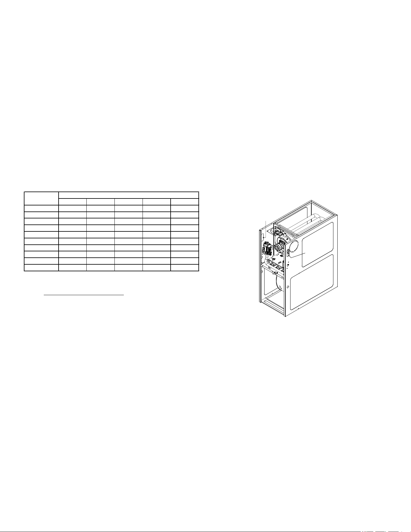
Gas line
entrance
Right side
gas entrance
(alternate)
General Furnace Layout
Figure 3
Upflow Installations
When the gas piping enters through the side of the furnace,
the installer must supply the following t tings (starting from
the gas valve):
• Close nipple.
• 90 degree elbow.
• Straight pipe to reach the exterior of the furnace.
A ground joint union, drip leg, and manual shuto valve must
also be supplied by the installer. In some cases, the installer
may also need to supply a transition piece from ½” to anoth-
er pipe size.
When the gas piping enters through the left side of the fur-
nace, the installer must supply the following ttings (starting
from the gas valve):
• 90 degree elbow.
• Straight pipe to reach the exterior of the furnace.
13
• A ground joint union, drip leg, and manual shuto valve
must also be supplied by the installer. In some cases,
the installer may also need to supply a transition piece
from ½ inch to another pipe size.
Counterflow Installations
When the gas piping enters through the left side of the fur-
nace, the installer must supply a straight pipe and a 90 de-
gree elbow to reach the exterior of the furnace.
A ground joint union, drip leg and manual shuto valve must
also be supplied by the installer. In most cases, the installer
may also need to supply a transition piece from ½” to anoth-
er pipe size. When the gas piping enters through the right
side of the furnace, the installer must supply the following
ttings (starting at the gas valve):
• Close Nipple
• 90 Degree Elbow
• Straight Pipe to Reach Exterior of Furnace.
Gas Piping Checks
Before placing unit in operation, leak test the unit and gas
connections.
WARNING
To avoid the possibility of explosion or fire, never use a
match or open flame to test leaks.
Check for leaks using an approved chloride-free soap and
water solution, an electronic combustible gas detector, or
other approved testing methods.
WARNING
To prevent property damage or personal injury due to fire,
the following instructions must be performed regarding gas
connections, pressure testing, location of shutoff valve and
installation of gas piping.
NOTE: Never exceed specied pressures for testing. Higher
pressure may cause gas valve failure.
Disconnect this unit and shuto valve from the gas supply
piping system before pressure testing the supply piping sys-
tem with pressures in excess of ½ psig (3.48 kPa).
This unit must be isolated from the gas supply system by
closing its manual shuto valve before pressure testing of
gas supply piping system with test pressures equal to or less
than ½ psig (3.48 kPa).
Propane Gas Tanks and Piping
A gas detecting warning system is the only reliable way to
detect a propane gas leak. Rust can reduce the level of
odorant in propane gas. Do not rely on your sense of smell.
Contact a local propane gas supplier about installing a gas
detecting warning system. If the presence of gas is suspect-
ed, follow the instructions on Page 3 of this manual.
All propane gas equipment must conform to the safety stan-
dards of the National Board of Fire Underwriters, NBFU
Manual 58.
For satisfactory operation, propane gas pressure must be
10 inch WC at the furnace manifold with all gas appli ances
in operation. Maintaining proper gas pressure depends on
three main factors:
1. Vaporization rate, depending on temperature of the
liquid, and “wetted surface” area of the con tainer or
containers.
2. Proper pressure regulation (Two-stage regulation is
recommended for both cost and eciency).
3. Pressure drop in lines between regulators, and between
second stage regulator and the appliance. Pipe size
will depend on length of pipe run and total load of all
appliances.
Complete information regarding tank sizing for vaporiza tion,
recommended regulator settings, and pipe sizing is avail-
able from most regulator manufacturers and propane gas
suppliers.
Use a pipe thread compound that is approved for natural
gas and LP Gas.
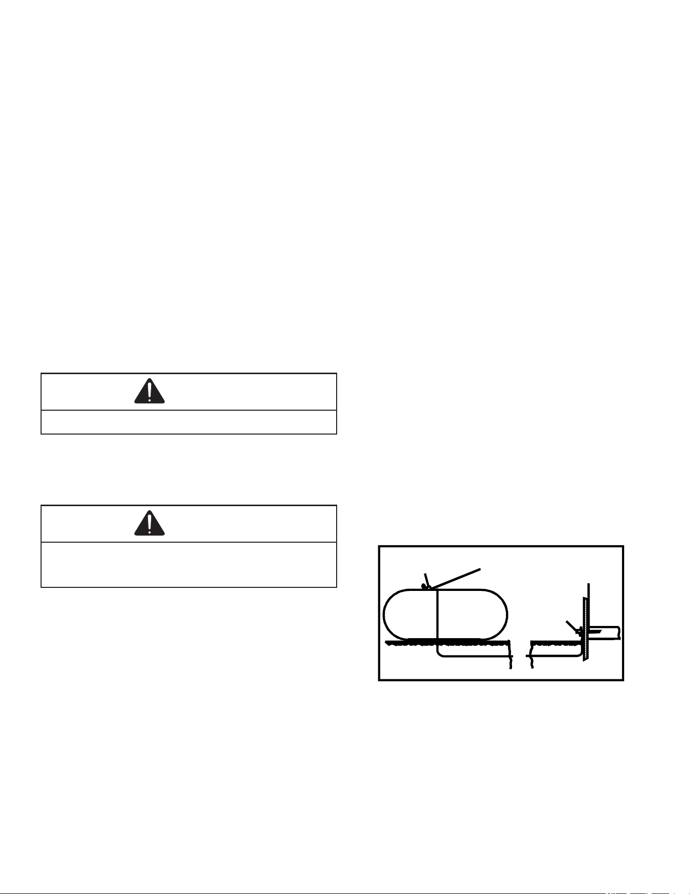
Refer to the following illustration for typical propane gas in-
stallations and piping.
200 PSIG
Maximum
5 to 15 PSIG
(20 PSIG Max.)
Continuous
11" W.C.
Second Stage
Regulator
First Stage
Regulator
Propane Gas Installation (Typ.)
Figure 4
14
Propane Gas Piping Charts
3/8" 1/2" 5/8" 3/4" 7/8" 1/2" 3/4"
10 730 1,700 3,200 5,300 8,300 3,200 7,500
20 500 1,100 2,200 3,700 5,800 2,200 4,200
30 400 920 2,000 2,900 4,700 1,800 4,000
40 370 850 1,700 2,700 4,100 1,600 3,700
50 330 770 1,500 2,400 3,700 1,500 3,400
60 300 700 1,300 2,200 3,300 1,300 3,100
80 260 610 1,200 1,900 2,900 1,200 2,600
100 220 540 1,000 1,700 2,600 1,000 2,300
125 200 490 900 1,400 2,300 900 2,100
150 190 430 830 1,300 2,100 830 1,900
175 170 400 780 1,200 1,900 770 1,700
200 160 380 730 1,100 1,800 720 1,500
Sizing Between First and Second Stage Regulator*
Maximum Propane Capacities listed are based on 2 psig pressure drop at 10 psig setting.
Capacities in 1,000 BTU/hour.
Nominal Pipe Size
Schedule 40
Tubing Size, O.D. Type L
Pipe or
Tubing
Length,
Feet
3/8" 1/2" 5/8" 3/4" 7/8" 1-1/8" 1/2" 3/4" 1" 1-1/4" 1-1/2"
10 39 92 199 329 501 935 275 567 1,071 2,205 3,307
20 26 62 131 216 346 630 189 393 732 1,496 2,299
30 21 50 107 181 277 500 152 315 590 1,212 1,858
40 19 41 90 145 233 427 129 267 504 1,039 1,559
50 18 37 79 131 198 376 114 237 448 910 1,417
60 16 35 72 121 187 340 103 217 409 834 1,275
80 13 29 62 104 155 289 89 185 346 724 1,066
100 11 26 55 90 138 255 78 162 307 630 976
125 10 24 48 81 122 224 69 146 275 567 866
150 9 21 43 72 109 202 63 132 252 511 787
200 8 19 39 66 100 187 54 112 209 439 665
250 8 17 36 60 93 172 48 100 185 390 590
Pipe or
Tubing
Length,
Feet
Nominal Pipe Size
Schedule 40
Tubing Size, O.D. Type L
Sizing Between Second Stage and Appliance Regulator*
Maximum Propane Capacities listed are based on 2 psig pressure drop at 10 psig setting.
Capacities in 1,000 BTU/hour.
Circulating Air
WARNING
Never allow the products of combustion, including carbon
monoxide, to enter the return duct work or circulation air
supply.
Duct systems and register sizes must be properly designed
for the CFM and external static pressure rat ing of the fur-
nace. Ductwork should be designed in accor dance with the
recommended methods of “Air Conditioning Contractors of
America” Manual D.
A duct system must be installed in accordance with Stan-
dards of the National Board of Fire Underwriters for the In-
stallation of Air Conditioning, Warm Air Heating and Ventilat-
ing Systems. Pamphlets No. 90A and 90B.
A closed return duct system must be used, with the return
duct connected to the furnace. NOTE: Ductwork must nev-
er be attached to the back of the furnace. For installations
requiring more than 1800 CFM, use a bottom return or two
sided return. Supply and return con nections to the furnace
may be made with exible joints to reduce noise transmis-
sion. To prevent the blower from inter fering with combustion
air or draft when a central return is used, a connecting duct
must be installed between the unit and the utility room wall.
A room, closet, or alcove must not be used as a return air
chamber.
When the furnace is used in connection with a cooling unit,
the furnace should be installed in parallel with or on the
upstream side of the cooling unit to avoid condensa tion in
the heating element. With a parallel ow arrange ment, the
dampers or other means used to control the ow of air must
be adequate to prevent chilled air from entering the furnace
and, if manually operated, must be equipped with means to
prevent operation of either unit unless the damper is in the
full heat or cool position.
When the furnace is installed without a cooling coil, it is rec-
ommended that a removable access panel be provided in
the outlet air duct. This opening shall be accessible when
the furnace is installed and shall be of such a size that the
heat exchanger can be viewed for visual light inspection
or such that a sampling probe can be inserted into the air
stream. The access panel must be made to prevent air leaks
when the furnace is in operation.
When furnace duct(s) supply air outside the space contain-
ing the furnace, a return air duct must terminate in the same
space as the supply duct and be sealed to the furnace casing.
When the furnace is heating, the temperature of the return
air entering the furnace must be between 55°F and 100°F.
Checking Duct Static
Refer to your furnace rating plate for the maximum ESP (ex-
ternal duct static) rating.
Total external static refers to static pressure created by all
components external to the furnace cabinet. Cooling coils,
lters, ducts, grilles, registers must all be considered when
reading your total external static pressure. The supply duct
pressure must be read between the furnace and the cool-
ing coil. This reading is usually taken by removing the “A”
shaped block o plate from the end on the coil; drilling a
test hole in it and reinstalling the block o plate. Take a duct
static reading at the test hole. Tape up the test hole after
your test is complete. The negative pressure must be read
between the lter and the furnace blower.
Too much external static pressure will result in insucient air
that can cause excessive temperature rise. This can cause
limit switch tripping and heat exchanger failure.
To determine total external duct static pressure, proceed as
follows:
1. With clean lters in the furnace, use a manometer to
measure the static pressure of the return duct at the
inlet of the furnace. (Negative Pressure)
15
2. Measure the static pressure of the supply duct. (Positive
Pressure)
3. The dierence between the two numbers is .4” w.c.
Example:
static reading from return duct = -.1” w.c.
static reading from supply duct = .3” w.c.
total external static pressure on this system = .4” w.c.
NOTE: Both readings may be taken simultaneously and
read directly on the manometer if so desired. If an air
conditioner coil or Electronic Air Cleaner is used in con-
junction with the furnace, the readings must also include
these components, as shown in the following drawing.
4. Consult proper tables for the quantity of air.
If the total external static pressure exceeds the maximum
listed on the furnace rating plate, check for closed dampers,
registers, undersized or poorly laid out duct work.
Digital
Manometer
Checking Static Pressure
Figure 5
Filters - Read This Section Before Installing The
Return Air Ductwork
Filters must be used with this furnace. Discuss lter main-
tenance with the building owner. Filters do not ship with this
furnace, but must be provided by the installer. Filters must
comply with UL900 or CAN/ULCS111 standards. Damage or
repairs due to the installation of the furnace without lters is
not covered under the warranty.
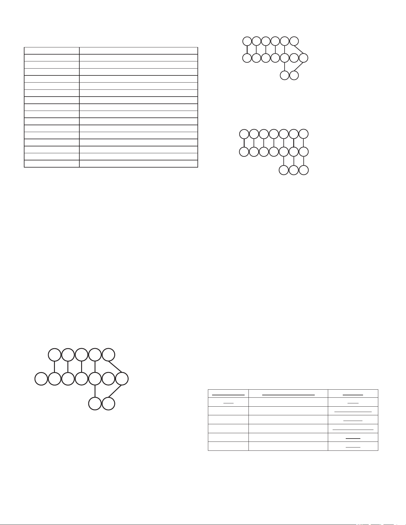
Upright Installations
Depending on the installation and/or customer preference,
diering lter arrangements can be applied. Filters can be
installed in the central return register or a side panel external
lter rack kit (upows), or the ductwork above a downow
furnace. As an alternative, a media air lter or electronic air
cleaner can be used as the primary lter.
Horizontal Installations
Filters must be installed in either the central return register
or in the return air duct work.
Circulation Air Filters
Figure 6 Figure 7
Figure 8 Figure 9
Figure 10
One of the most common causes of a problem in a forced
air heating system is a blocked or dirty lter. Circulating air
lters must be inspected monthly for dirt accumulation and
replaced if necessary. Failure to maintain clean lters can
cause premature heat exchanger failure.
16
A new home may require more frequent replacement until all
construction dust and dirt is removed.
Upflow Models Minimum Recommended Filter Size
*0403A* 1 - 16 X 25 Side or 1 - 14 X 24 Bottom Return
*0603A* 1 - 16 X 25 Side or 14 X 24 Bottom Return
*0603B* 1 - 16 X 25 Side or Bottom Return
*0803B* 1 - 16 X 25 Side or Bottom Return
*0804B* 1 - 16 X 25 Side or Bottom Return
*0804C* 1 - 16 X 25 Side or Bottom Return
*0805C* 1 - 16 X 25 Side or Bottom Return¹
*0805D* 2 - 16 X 25 Side or 1 - 20 X 25 Bottom Return¹
*1004C* 2 - 16 X 25 Side or 1 - 20 X 25 Bottom Return
*1005C* 2 - 16 X 25 Side or 1 - 20 X 25 Bottom Return
*1205D* 2 - 16 X 25 Side or 1 - 24 X 24 Bottom Return
Downflow Models
*0403A* 2 - 10 X 20 or 1 - 14 X 25 Top Return
*0603A* 2 - 10 X 20 or 1 - 14 X 25 Top Return
*0804B* 2 - 14 X 20 or 1 - 16 X 25 Top Return
*1005C* 2 - 14 X 20 or 1 - 20 X 25 Top Return
Larger filters may be used, filters may also be centrally located
¹ = Use 2 - 16 X 25 filters and two side returns or 20 X 25 filter on bottom
return if furnace is connected to a cooling unit over 4 tons nominal capacity
A combination of one side & bottom may be used instead of both sides
Electrical
24 Volt Thermostat Wiring
Important Note: Wiring routing must not interfere with circu-
lator blower operation, lter removal or routine maintenance.
Low voltage connections can be made through either the
right or left side panel. Thermostat wiring entrance holes
are located in the blower compartment. The following gure
shows connections for a “heat/cool system”.
This furnace is equipped with a 40 VA transformer to facili-
tate use with most cooling equipment. Consult the wiring di-
agram, located on the blower compartment door, for further
details of 115 Volt and 24 Volt wiring.
Thermostat Wiring Diagrams
Y
C
Y
C
G
R
W
Y2
Y/Y1
C
G
R
W/W1
W2
ROOM THERMOSTAT
INTEGRATED FURNACE
CONTROL MODULE
REMOTE COOLING UNIT
(SINGLE STAGE)
Thermostat - Single -Stage Heating with Single-Stage Cooling
Thermostat - Single -Stage Heating with Single-Stage Cooling
NOTE: To apply a single-stage Heating Thermostat, the staging option
must be set on single-stage.
Figure 11
Y
C
Y
C
G
R
W/W1
Y2
Y/Y1
C
G
R
W/W1
W2
ROOM THERMOSTAT
INTEGRATED FURNACE
CONTROL MODULE
REMOTE COOLING UNIT
(SINGLE STAGE)
W2
Thermostat - Two-Stage Heating with Single-Stage Cooling
Figure 12
Y1
C
Y1
C
G
R
W1
Y2
Y/Y1
C
G
R
W/W1
W2
ROOM THERMOSTAT
INTEGRATED FURNACE
CONTROL MODULE
REMOTE COOLING UNIT
(TWO STAGE)
W2
Y2
Y2
Thermostat - Two-Stage Heating with Two-Stage Cooling
Figure 13
Using a Single-Stage Heating Thermostat
A single-stage heating thermostat may be used to control
this furnace; however, the furnace is setup by default to use
a two-stage heating thermostat. To use a single stage heat-
ing thermostat the installer must make the desired selec-
tions in the user menus using the push button switches on
the control board. When a single stage heating thermostat is
used there are two options for controlling the timed transition
from low to high re: 1) Auto 2) Fixed Time.
• Press the Left or Right menu switches to get to the
•AHS menu.
• The menu will display these options: no10203060AUt
• Fixed time options are expressed in minutes on the
display as: 10203060.
• If AUt (Automatic) is selected, the actual timing for the
transition to 2nd stage heat will be calculated by the
control board based on length of run time of previous
heating cycles (duty cycle).
• Press the center switch to save the selection.
In Auto mode, the transition to 2nd stage heat will vary be-
tween 1 to 12 minutes.
Duty Cycle %
Heating Stage Timing
Demand
0-38
1
st
Stage, 12 minute 2
nd
Stage
Light
39-50
1
st
Stage, 10 minute 2
nd
Stage
Light to Average
51-62
1
st
Stage, 7 minute 2
nd
Stage
Average
63-75
1
st
Stage, 5 minute 2
nd
Stage
Average to Heavy
76-88
1
st
Stage, 3 minute 2
nd
Stage
Heavy
89-100
1
st
Stage, 1 minute 2
nd
Stage
Heavy
17
Using a Two Stage Heating Thermostat
• The furnace is setup by default to use a two-stage
heating thermostat.
• The menu may be accessed by pressing the Left or Right
menu switches to get to theAHSmenu.
• The menu will display these options: no10203060
AUt.
• Select no.
• Press the center switch to save the selection.
• In this mode only a W2 signal on the control board will
bring on 2nd stage heat.
Fossil Fuel Applications
This furnace can be used in conjunction with a heat pump
in a fossil fuel application. A fossil fuel application refers to
a combined gas furnace and heat pump installation which
uses an outdoor temperature sensor to determine the most
cost ecient means of heating (heat pump or gas furnace).
A heat pump thermostat with three stages of heat is required
to properly use a two-stage furnace in conjunction with a
heat pump. Refer to the fossil fuel kit installation instructions
for additional thermostat requirements.
Strictly follow the wiring guidelines in the fossil fuel kit instal-
lation instructions. All furnace connections must be made
to the furnace two-stage integrated control module and the
“FURNACE” terminal strip on the fossil fuel control board.
Twinning
Two furnaces of the same model may be twinned. The in-
tegrated control board has a 3/16” terminal labeled “TWIN”
located beside the low voltage thermostat connection strip.
Twinning allows simultaneous operation of two furnaces and
forces the indoor blower motors of each furnace to operate
synchronously into a common duct system. Using the twin-
ning function will require only eld installed wiring with no
external kits or parts. The staging and speed tap options
must be set the same on both furnaces.
NOTE: Each furnace must be connected to it’s own 115 VAC
power supply. The L1 connection to each furnace must be in
phase (connected to circuit breakers on the same 115 VAC
service panel phase leg). To verify that the furnaces are in
phase, check from L1 to L1 on each furnace with a voltme-
ter. If the furnaces are in phase, the voltage between both
furnaces will be ZERO.
ROOM THERMOSTAT
Y2
Y/Y1
C
G
R
W/W1
W2
Y2
Y/Y1
C
G
R
W/W1
W2
Y2
Y/Y1
C
G
R
W/W1
W2
TWIN
TWIN
COND UNIT
CONTACTOR
COND UNIT
CONTACTOR
FURNACE 1
FURNACE 2
Figure 14
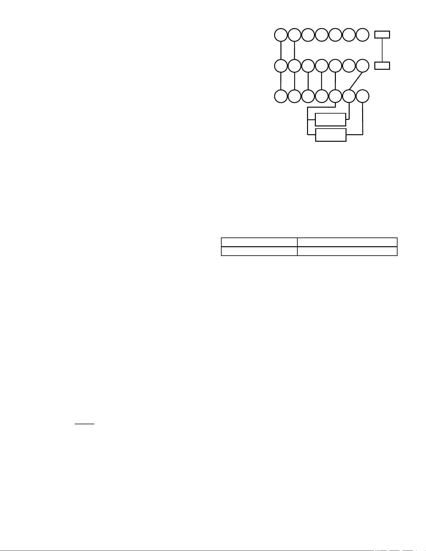
115 Volt Line Connection of Accessories (Humidifi-
er and Electronic Air Cleaner)
The furnace integrated control module is equipped with line
voltage accessory terminals for controlling power to an op-
tional eld-supplied humidier and/or electronic air cleaner.
The accessory load specications are noted in the chart
below:
Humidifier
1.0 Amp maximum at 120 VAC
Electronic Air Cleaner
1.0 Amp maximum at 120 VAC
Turn OFF power to the furnace before installing any acces-
sories. Follow the humidier or air cleaner manufacturers’ in-
structions for locating, mounting, grounding, and controlling
these accessories. Accessory wiring connections are to be
made through the 1/4” quick connect terminals provided on
the furnace integrated control module. The humidier and
electronic air cleaner hot terminals are identied as HUM H
and EAC H. The humidier and electronic air cleaner neutral
terminals are identied as NEUTRAL. All eld wiring must
conform to applicable codes. Connections should be made
as shown.
If it is necessary for the installer to supply additional line
voltage wiring to the inside of the furnace, the wiring must
conform to all local codes, and have a minimum temperature
rating of 105°C. All line voltage wire splices must be made
inside the furnace junction box.
The integrated control module humidier terminal (HUM
H) is energized with 115 volts whenever the induced draft
blower is energized. The integrated control module electron-
ic air cleaner terminal (EAC H) is energized with 115 volts
whenever the circulator blower is energized. This terminal
can also be used to provide 115 volt power to a humidier
transformer. The remaining primary transformer wire would
be connected to the Line N on the control board.
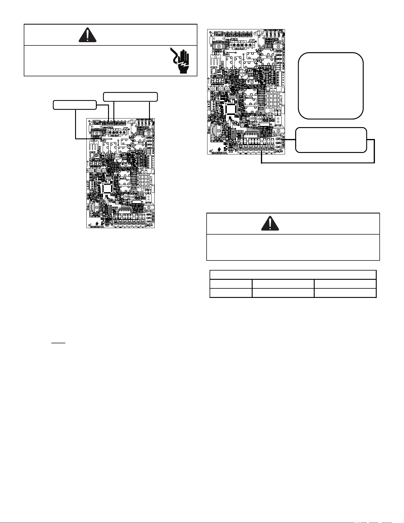
18
WARNING
HIGH VOLTAGE!
To avoid personal injury or death due to electri-
cal shock, disconnect electrical power before
servicing or changing any electrical wiring.
W2 W/W1 R G C Y/Y1 Y2
115 VAC EAC
115 VAC HUM
Accessories - Accessories Wiring
Figure 15
Low Voltage Humidifier
The furnace integrated control module is equipped with
a low voltage terminal for providing power to an optional
eld-supplied 24 volt humidier. The 24V HUM terminal is
energized any time the draft inducer is powered. See con-
nection diagram below.
NOTE: This is a 24 volt circuit only, the common connec-
tion must be on C terminal of the low voltage terminal strip
(where thermostat wires are connected). Wiring for this cir-
cuit must NOT be connected to the line N location where line
voltage neutral wires are connected.
W2 W/W1 R G C Y/Y1 Y2
24V HUM
Terminal is
energized when
pressure switch
is closed
24 VOLT HUM.
& HUMIDISTAT
24 Volt Humidier Connection
Figure 16
Gas Supply and Piping
WARNING
To avoid possible unsatisfactory operation of equipment
damage due to underfiring pf equipment, use the proper size
of natural/propane gas piping needed when running pipe from
the meter/tank to the furnace.
Natural Gas Minimum: 4.5" w.c. Maximum: 10.0" w.c.
Propane Gas Minimum: 11.0" w.c. Maximum: 13.0" w.c.
INLET GAS SUPPLY PRESSURE
The furnace rating plate includes the approved furnace gas
input rating and gas types. The furnace must be equipped to
operate on the type of gas applied. This includes any con-
version kits required for alternate fuels and/or high altitude.
Inlet gas supply pressures must be maintained within the
ranges specied in the adjacent table. The supply pressure
must be constant and available with all other household gas
red appliances operating. The minimum gas supply pres-
sure must be maintained to prevent unreliable ignition. The
maximum must not be exceeded to prevent unit overring.
High Altitude Derate
When this furnace is installed at high altitude, the appropri-
ate High Altitude orice kit must be applied. This is required
due to the natural reduction in the density of both the gas
fuel and combustion air as altitude increases. The kit will
provide the proper design certied input rate within the spec-
ied altitude range.
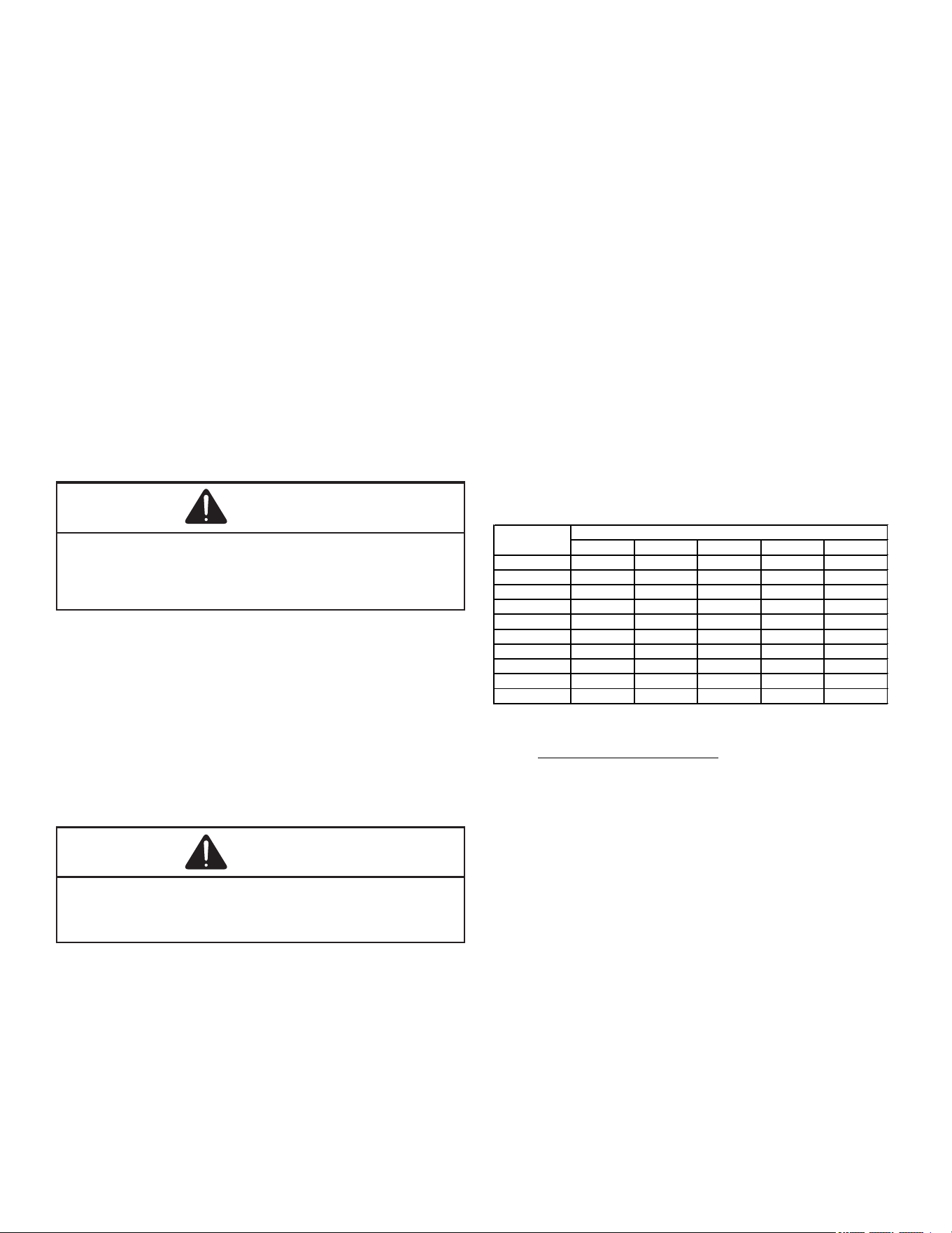
19
High altitude kits are purchased according to the installation
altitude and usage of either natural or propane gas. Consult
the furnace Specication Sheet for appropriate kits.
Do not derate the furnace by adjusting the manifold pressure
to a lower pressure than specied on the furnace rating plate.
The combination of the lower air density and a lower manifold
pressure will prohibit the burner orice from drawing the prop-
er amount of air into the burner. This may cause incomplete
combustion, ashback, and possible yellow tipping.
In some areas the gas supplier may articially derate the
gas in an eort to compensate for the eects of altitude.
If the gas is articially derated, the appropriate orice size
must be determined based upon the BTU/ft
3
content of the
derated gas and the altitude. Refer to the National Fuel Gas
Code, NFPA 54/ANSI Z223.1, and information provided by
the gas supplier to determine the proper orice size.
A dierent pressure switch may be required at high altitude
regardless of the BTU/ft
3
content of the fuel used. Consult
the furnace Specication Sheet for pressure switch.
WARNING
Possible property damage, personal injury or death may
occur if the correct conversion kits are not installed. The
appropriate kits must be applied to ensure safe and proper
furnace operation. All conversions must be performed by a
qualified installer or service agency.
Propane Gas Conversion
This unit is congured for natural gas, but may be converted
for use with L.P. gas. Refer to the section on PROPANE GAS/
HIGH ALTITUDE INSTALLATIONS for L.P. kit selection.
Consult the furnace Specication Sheet for a listing of ap-
propriate kits. The indicated kits must be used to insure safe
and proper furnace operation. All conversions must be per-
formed by a qualied installer, or service agency.
CAUTION
To prevent unreliable operation or equipment damage, the
inlet gas supply pressure must be as specified on the unit
rating plate with all other household gas fired appliances
operating.
Gas Valve
This unit is equipped with a 24 volt gas valve controlled
during furnace operation by the integrated control module.
As shipped, the valve is congured for natural gas. The valve
is eld convertible for use with propane gas by replacing the
regulator spring with a propane gas spring from an appro-
priate manufacturer’s propane gas conversion kit. Taps for
measuring the gas supply pressure and manifold pressure
are provided on the valve.
The gas valve has a manual ON/OFF control located on the
valve itself. This control may be set only to the “ON” or “OFF”
position. Refer to the lighting instructions label or Startup
Procedure & Adjustment for use of this control during start
up and shut down periods.
Gas Piping Connections
The gas piping supplying the furnace must be properly sized
based on the gas ow required, specic gravity of the gas,
and length of the run. The gas line installation must comply
with local codes, or in their absence, with the latest edition of
the National Fuel Gas Code, NFPA 54/ANSI Z223.1.
Natural Gas Capacity of Pipe
In Cubic Feet of Gas Per Hour (CFH)
Length of Nominal Black Pipe Size
Pipe in Feet 1/2" 3/4" 1" 1 1/4" 1 1/2"
10 132 278 520 1050 1600
20 92 190 350 730 1100
30 73 152 285 590 980
40 63 130 245 500 760
50 56 115 215 440 670
60 50 105 195 400 610
70 46 96 180 370 560
80 43 90 170 350 530
90 40 84 160 320 490
100 38 79 150 305 460
(Pressure 0.5 psig or less and pressure drop of 0.3" W.C.; Based on
0.60 Specif ic Gravity Gas)
CFH =
BTUH Furnace Input
Heating Value of Gas (BTU/Cubic Foot)
To connect the furnace to the building’s gas piping, the in-
staller must supply a ground joint union, drip leg, manual
shuto valve, and line and ttings to connect to gas valve.
In some cases, the installer may also need to supply a tran-
sition piece from ½” pipe to a larger pipe size.
The following stipulations apply when connecting gas pip-
ing. Refer to Gas Piping Connections gure for typical gas
line connections to the furnace.
• Gas piping must be supported external to the furnace
cabinet so that the weight of the gas line does not distort
the burner rack, manifold or gas valve.
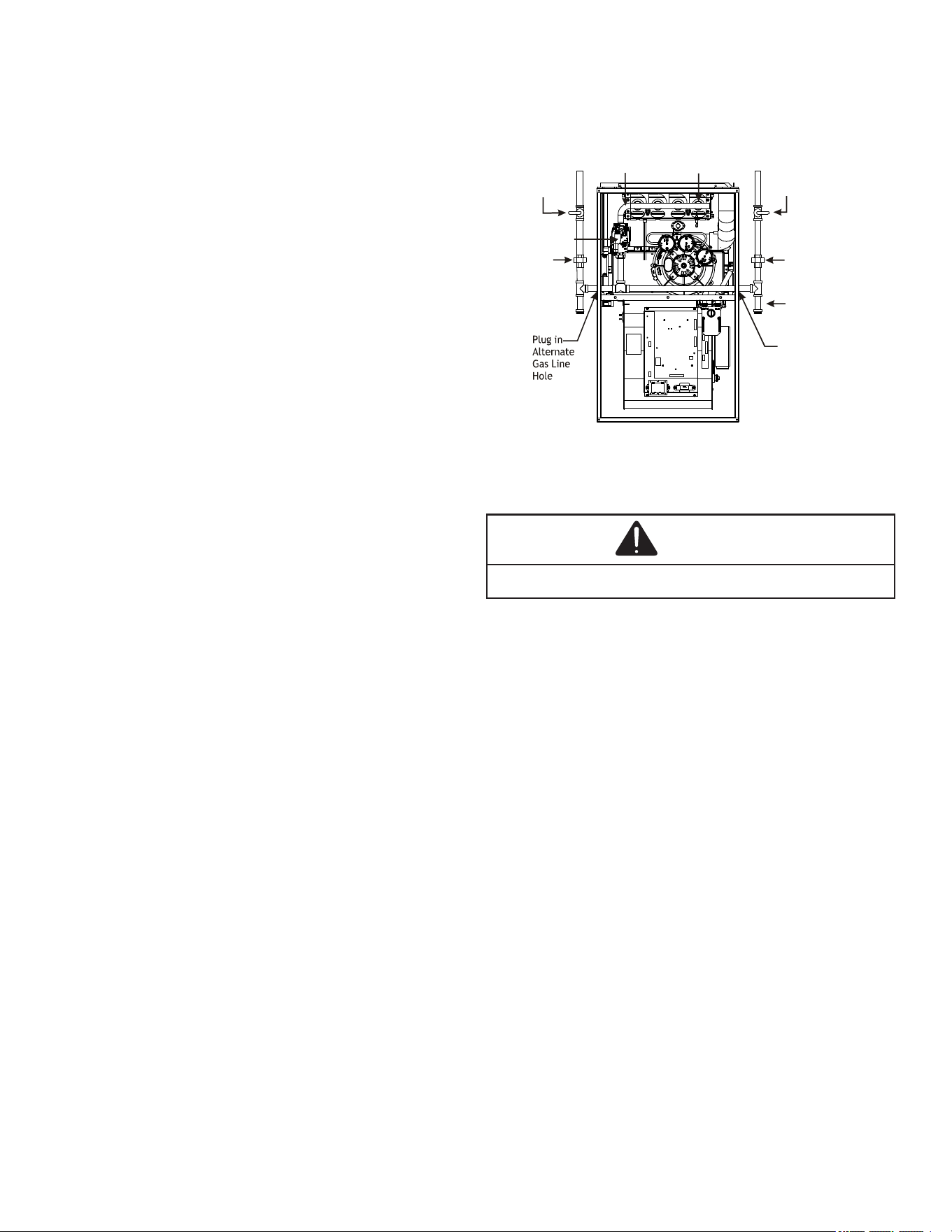
20
• Use black iron or steel pipe and ttings for building
piping. Where possible, use new pipe that is properly
chamfered, reamed, and free of burrs and chips. If old
pipe is used, be sure it is clean and free of rust, scale,
burrs, chips, and old pipe joint compound.
• Use pipe joint compound on male threads ONLY. Always
use pipe joint compound (pipe dope) that is APPROVED
FOR ALL GASES. DO NOT apply compound to the rst
two threads.
• Use ground joint unions.
• Install a drip leg to trap dirt and moisture before it can
enter the gas valve. The drip leg must be a minimum of
three inches long.
• Install a 1/8” NPT pipe plug tting, accessible for test
gage connection, immediately upstream of the gas
supply connection to the furnace.
• Always use a back-up wrench when making the
connection to the gas valve to keep it from turning. The
orientation of the gas valve on the manifold must be
maintained as shipped from the factory. Maximum torque
for the gas valve connection is 375 in-lbs; excessive
over-tightening may damage the gas valve.
• Install a manual shuto valve between the gas meter and
unit within six feet of the unit. If a union is installed, the
union must be downstream of the manual shuto valve,
between the shuto valve and the furnace.
• Tighten all joints securely.
• Connect the furnace to the building piping by one of the
following methods:
– Rigid metallic pipe and ttings.
– Semi-rigid metallic tubing and metallic ttings. Alu-
minum alloy tubing must not be used in exterior lo-
cations. In order to seal the grommet cabinet pene-
tration, rigid pipe must be used to reach the outside
of the cabinet. A semi-rigid connector to the gas pip-
ing may be used from there.
• Use listed gas appliance connectors in accordance with
their instructions. Connectors must be fully in the same
room as the furnace.
• Protect connectors and semirigid tubing against
physical and thermal damage when installed. Ensure
aluminum-alloy tubing and connectors are coated to
protect against external corrosion when in contact with
masonry, plaster, or insulation, or subjected to repeated
wetting by liquids such as water (except rain water),
detergents, or sewage.
The gas piping may enter the left or right side of the furnace
cabinet. The installer must supply rigid pipe long enough to
reach the outside of the cabinet to seal the grommet cabinet
penetration. A semi-rigid connector to the gas piping can be
used outside the cabinet per local codes. ½” NPT pipe and
ttings are required. For models with an “L” shaped mani-
fold, a 4 ½” long nipple is required. For models with a hook
shaped manifold, a 2” long nipple is required.
A semi-rigid connector to the gas piping can be used outside
the cabinet per local codes. From the elbow, the length of
pipe and the ttings required will vary by the side chosen, lo-
cation of union and cabinet width. The union may be placed
inside or outside of the cabinet.
Alternate
Gas Line
Location
Gas Valve
Burners
Manual Shut Off Valve
(upstream from
ground joint
pipe union)
Drip Leg
Grommet
in Standard
Gas Line
Hole
*Ground
Joint
Pipe
Union
*Ground
Joint
Pipe
Union
*NOTE: Union may be inside furnace cabinet where allowed by local codes.
Manifold
UPFLOW
Figure 17
Gas Connections
WARNING
To avoid the possibility of explosion or fire, never use a
match or open flame to test leaks.
Gas Piping Checks
Before placing unit in operation, leak test the unit and gas
connections.
Check for leaks using an approved chloride-free soap and
water solution, an electronic combustible gas detector, or
other approved testing methods.
NOTE: Never exceed specied pressures for testing. Higher
pressure may damage the gas valve and cause subsequent
overring, resulting in heat exchanger failure.
Disconnect this unit and shuto valve from the gas supply
piping system before pressure testing the supply piping sys-
tem with pressures in excess of ½ psig (3.48 kPa).
Isolate this unit from the gas supply piping system by closing
its external manual gas shuto valve before pressure testing
supply piping system with test pressures equal to or less
than ½ psig (3.48 kPA).
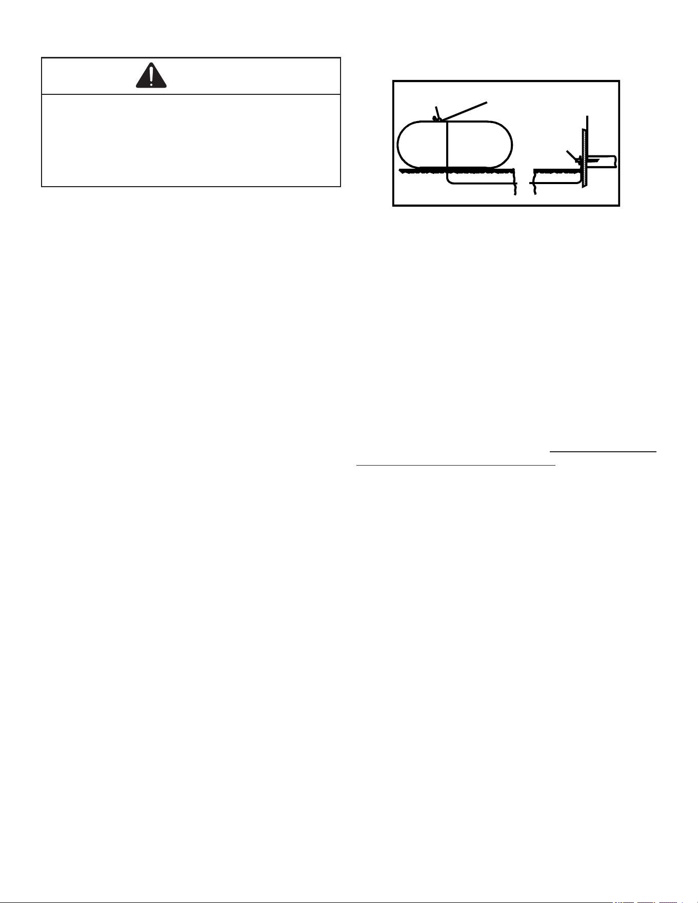
21
Propane Gas Tanks and Piping
WARNING
If the gas furnace is installed in a basement, an excavat-
ed area or confined space, it is strongly recommended to
contact a propane supplier to install a gas detected warning
device in case of a gas leak.
• Since propane gas is heavier than air, any leaking gas
can settle in any low areas or confined spaces.
• Propane gas odorant may fade, making the gas undetect-
able except a warning device.
A gas detecting warning system is the only reliable way to
detect a propane gas leak. Rust can reduce the level of
odorant in propane gas. Do not rely on your sense of smell.
Contact a local propane gas supplier about installing a gas
detecting warning system. If the presence of gas is suspect-
ed, follow the instructions listed in the Safety Considerations
section of this manual.
All propane gas equipment must conform to the safety stan-
dards of the National Board of Fire Underwriters, NBFU
Manual 58.
For satisfactory operation, propane gas pressure must be
10” WC at the furnace manifold with all gas appli ances in op-
eration. Maintaining proper gas pressure depends on three
main factors:
1. Vaporization rate, depending on temperature of the
liquid, and “wetted surface” area of the con tainer or
containers.
2. Proper pressure regulation (Two-stage regulation is
recommended for both cost and eciency).
3. Pressure drop in lines between regulators, and between
second stage regulator and the appliance. Pipe size
will depend on length of pipe run and total load of all
appliances.
Complete information regarding tank sizing for vaporiza tion,
recommended regulator settings, and pipe sizing is avail-
able from most regulator manufacturers and propane gas
suppliers.
Since propane gas will quickly dissolve white lead and most
standard com mercial compounds, special pipe dope must
be used. Always use a pipe thread sealant approved for all
gases.
Refer to the this illustration for typical propane gas installa-
tions and piping.
200 PSIG
Maximum
5 to 15 PSIG
(20 PSIG Max.)
Continuous
11" W.C.
Second Stage
Regulator
First Stage
Regulator
Propane Gas Installation (Typ.)
Figure 18
Circulating Air & Filters
Duct work - Air Flow
Duct systems and register sizes must be properly designed
for the CFM and external static pressure rat ing of the furnace.
Design the ductwork in accor dance with the recommended
methods of “Air Conditioning Contractors of America” Manual D.
Install the duct system in accordance with Standards of the
National Board of Fire Underwriters for the Installation of Air
Conditioning, Warm Air Heating and Ventilating Systems.
Pamphlets No. 90A and 90B.
A closed return duct system must be used, with the return
duct connected to the furnace. NOTE: Ductwork must never
be attached to the back of the furnace. For upow installa-
tions requiring 1800 CFM or more, use either two side re-
turns or bottom return or a combination of side /bottom. Flex-
ible joints may be used for supply and return con nections to
reduce noise transmission. To prevent the blower from inter-
fering with combustion air or draft when a central return is
used, a connecting duct must be installed between the unit
and the utility room wall. Never use a room, closet, or alcove
as a return air chamber.
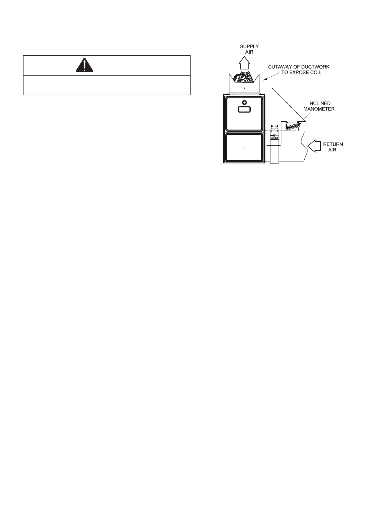
22
Checking Duct Static
Refer to your furnace rating plate for the maximum ESP (ex-
ternal duct static) rating.
WARNING
Never allow the products of combustion, including carbon
monoxide, to enter the return duct work or circulation air
supply.
Total external static refers to everything external to the fur-
nace cabinet. Cooling coils, lters, ducts, grilles, registers
must all be considered when reading your total external
static pressure. The supply duct pressure must be read be-
tween the furnace and the cooling coil.
This reading is usually taken by removing the “A” shaped
block o plate from the end on the coil; drilling a test hole
in it and reinstalling the block o plate. Take a duct static
reading at the test hole. Tape up the test hole after your test
is complete. The negative pressure must be read between
the lter and the furnace blower.
Too much external static pressure will result in insucient air
that can cause excessive temperature rise. This can cause
limit switch tripping and heat exchanger failure.
To determine total external duct static pressure, proceed as
follows:
1. With clean lters in the furnace, use a manometer to
measure the static pressure of the return duct at the
inlet of the furnace. (Negative Pressure)
2. Measure the static pressure of the supply duct. (Positive
Pressure)
3. The dierence between the two numbers is .4” w.c.
Example:
static reading from return duct = -.1” w.c.
static reading from supply duct = .3” w.c.
total external static pressure on this system = .4” w.c.
NOTE: Both readings may be taken simultaneously and read
directly on the manometer if so desired. If an air conditioner
coil or Electronic Air Cleaner is used in conjunction with the
furnace, the readings must also include theses components,
as shown in the following drawing.
4. Consult proper tables for the quantity of air.
If the total external static pressure exceeds the maximum list-
ed on the furnace rating plate, check for closed dampers, reg-
isters, undersized and/or oversized poorly laid out duct work.
The temperature rise of the furnace must be within the tem-
perature rise range listed on the furnace rating plate.
Checking Static Pressure
Figure 19
Furnace Startup
1. Close the manual gas shuto valve external to the
furnace.
2. Turn o the electrical power to the furnace.
3. Set the room thermostat to the lowest possible setting.
4. Remove the burner compartment door.
NOTE: This furnace is equipped with an ignition device
which automatically lights the burner. Do not try to light the
burner by hand.
5. Move the furnace gas valve manual control to the OFF
position.
6. Wait ve minutes then smell for gas. Be sure check near
the oor as some types of gas are heavier than air.
7. If you smell gas after ve minutes, immediately follow
the safety instructions in the Safety Considerations on
page 2 of this manual. If you do not smell gas after ve
minutes, move the furnace gas valve manual control to
the ON position.
8. Replace the burner compartment door.
9. Open the manual gas shuto valve external to the
furnace.
10. Turn on the electrical power to the furnace.
11. Adjust the thermostat to a setting above room
temperature.
12. After the burners are lit, set the thermostat to desired
temperature.
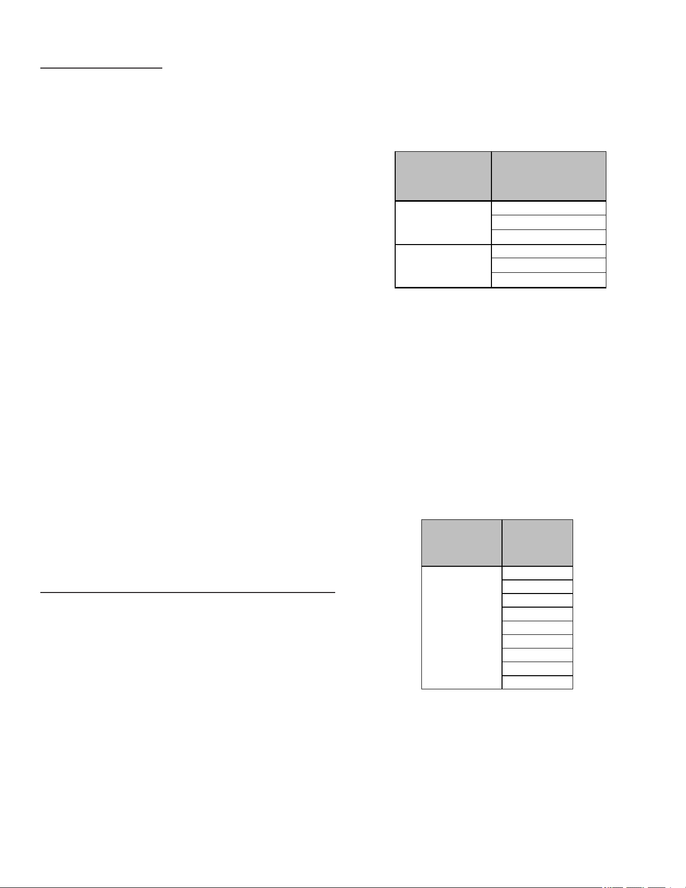
23
Gas Heat Sequence of Operation
Call for 1st Stage Heat
• On a call for heat, the thermostat contacts close & the
control board receives 24 VAC on the W1 terminal.
• The control board microcomputer runs its self-check
routine.
• The control veries the limit switch is closed (24 VAC on
Pin 8 of the 12 Pin connector).
• The control veries that pressure switch circuit is open
(0 VAC on Pin 5).
• The control module performs a gas valve circuitry check
to verify gas valve relay state and presence of voltage
at the valve.
• The system will energize the Induced draft blower.
• The pre-purge period begins once the low re pressure
switch is detected closed (24 VAC on Pin 5).
• After the completion of pre-purge, the control will
energize the igniter.
• After completion of the ignitor warm-up period:
• The gas valve is energized.
• The ignitor is de-energized as soon as ame is sensed.
• After 30 seconds the indoor blower is energized on
heating speed.
• When using a single-stage heating thermostat, the
furnace will transition to 2nd stage gas heat by either a
xed time or auto mode depending on menu selections
made by the installer.
• The inducer motor is enabled at high speed.
• Closure of the 2nd stage pressure switch will energize
the high re stage of the gas valve.
• The 2nd stage gas heat speed of the indoor blower is
energized
• When the thermostat is satised:
• The gas valve is de-energized.
• The inducer remains energized for the post purge period
(15 seconds).
• The indoor blower runs for the selected o delay period
(90 seconds by default, adjustable from 30 – 180
seconds).
Call for 2nd Stage Heat During 1st Stage Heat Operation
• The control board receives a 24 VAC signal on the W2
terminal.
• The inducer motor is enabled at high speed.
• Closure of the 2nd stage pressure switch will energize
the high re stage of the gas valve.
• The 2nd stage gas heat speed of the indoor blower is
energized.
Heating Mode Speed Selection
To change the main blower speed in HEATING mode, follow
the following steps:
1. Press the left or right switch until LED displays “gA1”
(for single-stage HEATING) or “gA2” (for two-stage
HEATING). Press the center switch and LED will display
the selected speed number as Fxx (xx: Blower speed
number).
2. The control will rotate available speed number every
time left / right switches are pressed. The table below
shows the available speeds for low & high heat mode.
3. Press the center switch to save the selection.
NOTE: Always refer to the Heating Chart to choose from
available heating speeds
THERMOSTATCALL AVAILABLESPEEDS
W/W1
F01(DEFAULT)
F03
F04
W2
F02(DEFAULT)
F04
F05
One and Two-Stage Heating Speed Table for 2 Stage IFC
Continuous Fan Mode Speed Selection
To change the main blower speed in circulation mode, follow
the following steps:
1. Press the left or right switch until LED displays “FSd”.
Press the center switch and LED will display the selected
speed number as Fxx (xx: Blower speed number from 1
to 9). F03 is the default speed for circulation.
2. The control will rotate available speed number every
time left/right switches are pressed. All 9 speeds are
available for circulation.
3. When the center switch is pressed, the current displayed
speed will be selected, and control will immediately apply
that speed setting.
THERMOSTAT
CALL
AVAILABLE
SPEEDS
G
F01
F02
F03(DEFAULT)
F04
F05
F06
F07
F08
F09
Circulation Speed Table for 2 Stage IFC
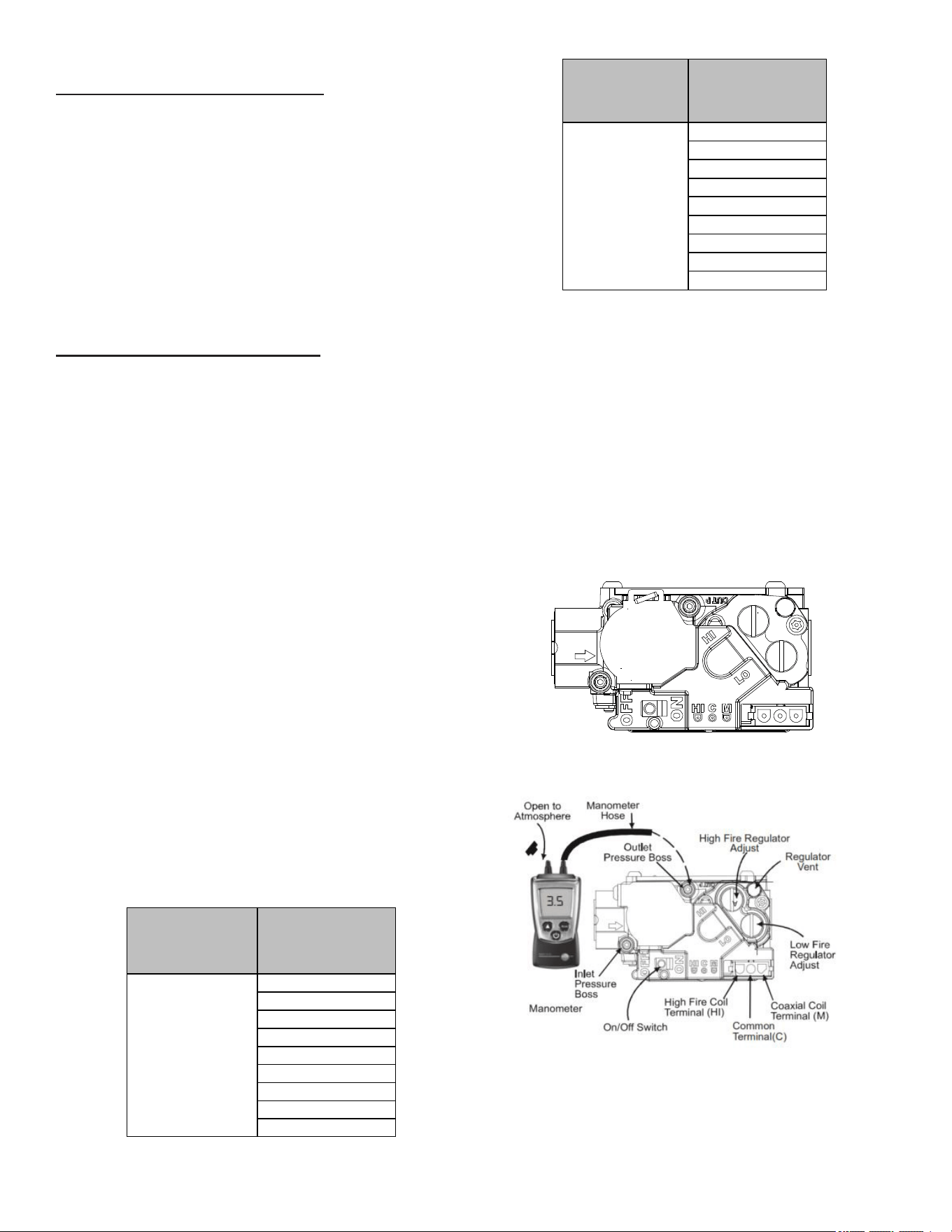
24
Cooling Mode Sequence of Operation
Low Stage Cooling Mode Sequence:
On a call for low stage cooling, the Y/Y1 or Y/Y1 and G ther-
mostat contacts close signaling the furnace control board
with 24 VAC on Y/Y1 or Y/Y1 and G terminals.
• The 7-Segment will display the cool mode:1AC
• The compressor and condenser fan are energized.
• The circulator fan is energized at low cool speed after
a cool on delay. The electronic air cleaner will also be
energized.
• After the thermostat is satised, the compressor is de-
energized and the Cool Mode Fan O Delay period begins.
• Following the Cool Mode Fan O Delay period, the cool
circulator and air cleaner relay are de-energized.
2nd Stage Cooling Mode Sequence:
On a call for 2nd stage cooling, the Y2 or Y2 and G thermo-
stat contacts close signaling the furnace control board with
24 VAC on Y2 or Y2 and G terminals.
• The 7-Segment will display the cool mode: 2AC
• The compressor and condenser fan are energized.
• The circulator fan is energized at cool speed after a
cool on delay. The electronic air cleaner will also be
energized.
• After the thermostat is satised, the compressor is
de-energized and the Cool Mode Fan O Delay period
begins.
• Following the Cool Mode Fan O Delay period, the cool
circulator and air cleaner relay are de-energized
Cooling Mode Speed Selection
To change the main blower speed in COOLING mode, follow
the following steps:
1. Press the left or right switch until LED displays “AC1
“(for single stage COOLING) or “AC2 “(for two-stage
COOLING). Press the center switch and LED will display
the selected speed number as Fxx (xx: Blower speed
number from 1 to 9).
2. The control will rotate available speed number every time
left/right switches are pressed. All 9 speeds are available
for both Single and Two Stage cooling.
3. When the center switch is pressed, the current displayed
speed will be selected, and control will apply the newly
selected speed in next cooling call.
THERMOSTATCALL AVAILABLESPEEDS
Y/Y1
F01
F02
F03
F04(DEFAULT)
F05
F06
F07
F08
F09
Single-Stage Cooling Speed Table for 2 Stage IFC
THERMOSTATCALL AVAILABLESPEEDS
Y2
F01
F02
F03
F04
F05(DEFAULT)
F06
F07
F08
F09
Two-Stage Cooling Speed Table for 2 Stage IFC
Furnace Shutdown
1. Set the thermostat to the lowest setting. The integrated
control will close the gas valve and extinguish ame.
Following a 15 second delay, the induced draft blower
will be de-energized. After the blower o delay time
expires, the blower de-energizes.
2. Remove the burner compartment door and move the
furnace gas valve manual control to the OFF position.
3. Close the manual gas shuto valve external to the
furnace.
4. Replace the burner compartment door.
Gas Supply Pressure Measurement
White-Rodgers Model 36J54 (Two-Stage)
White-Rogers Model 36J54 (Two-Stage)
Figure 20A
White-Rogers Model 36J54 Connected to Manometer
Figure 20B
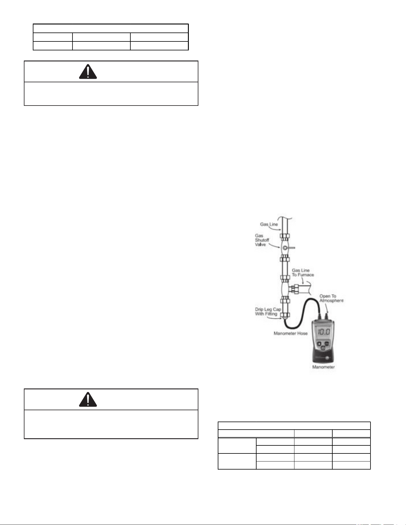
25
Natural Gas Minimum: 4.5" w.c. Maximum: 10.0" w.c.
Propane Gas Minimum: 11.0" w.c. Maximum: 13.0" w.c.
INLET GAS SUPPLY PRESSURE
CAUTION
To prevent unreliable operation or equipment damage, the gas
manifold pressure must be as specified on the unit rating plate
with all other household gas fired appliances operating.
The line pressure supplied to the gas valve must be within
the range specied below. The supply pressure can be mea-
sured at the gas valve inlet pressure tap or at a hose tting
installed in the gas piping drip leg. The supply pressure must
be measured with the burners operating. To measure the
gas supply pressure, use the following procedure.
1. Turn OFF gas to furnace at the manual gas shuto valve
external to the furnace.
2. Connect a calibrated water manometer (or appropriate
gas pressure gauge) at either the gas valve inlet pressure
tap or the gas piping drip leg. See White-Rodgers 36J54
gas valve (Figure 20B) to locate the inlet pressure tap.
NOTE: If using the inlet pressure tap on the White-Rodgers
36J54 gas valve, then use the 36G/J Valve Pressure Check
Kit, Part No. 0151K00000S.
3. Turn ON the gas supply and operate the furnace and
all other gas consuming appliances on the same gas
supply line.
4. Measure furnace gas supply pressure with burners ring.
Supply pressure must be within the range specied in
the Inlet Gas Supply Pressure table.
If supply pressure diers from table, make the necessary
adjustments to pressure regulator, gas piping size, etc., and/
or consult with local gas utility.
5. Turn OFF gas to furnace at the manual shuto valve and
disconnect manometer. Reinstall plug before turning on
gas to furnace.
6. Turn OFF any unnecessary gas appliances stated in
step three.
Gas Manifold Pressure Measurement
and Adjustment
CAUTION
To prevent unreliable operation or equipment damage, the
gas manifold pressure must be as specified on the unit rating
plate. Only minor adjustments should be made by adjusting
the gas valve pressure regulator.
Only small variations in gas pressure should be made by
adjusting the gas valve pressure regulator. The manifold
pressure must be measured with the burners operating. To
measure and adjust the manifold pressure, use the following
procedure.
1. Turn OFF gas to furnace at the manual gas shuto valve
external to the furnace.
2. Turn o all electrical power to the system.
3. Outlet pressure tap connections:
White-Rodgers 36J54 valve: Back outlet pressure
test screw (inlet/outlet pressure tap) out one turn
(counterclockwise, not more than one turn).
4. Attach a hose and manometer to outlet pressure tap.
5. Turn ON the gas supply.
Run High Fire
The furnace should be inspected by a qualied installer, or
service agency at least once per year. This check should be
performed at the beginning of the heating season. This will
ensure that all furnace components are in proper working or-
der and that the heating system functions appropriately. Pay
particular attention to the following items. Repair or service
as necessary.
Measuring Inlet Gas Pressure (Alt. Method)
Figure 21
NOTE: When converting from natural gas to L.P. consult
your distributor for proper conversion kit.
Range Nominal
Low Stage 1.6 - 2.2" w.c. 1.9" w.c.
High Stage 3.2 - 3.8" w.c. 3.5" w.c.
Low Stage 5.7 - 6.3" w.c. 6.0" w.c.
High Stage 9.7 - 10.3" w.c. 10.0" w.c.
Manifold Gas Pressure
Gas
Natural
Propane
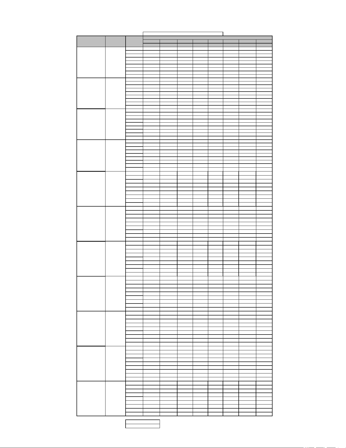
26
Airflow Tables
GM9C80
0.1 0.2 0.3 0.4 0.5 0.6 0.7 0.8
CFM CFM CFM CFM CFM CFM CFM CFM
F01
749 697 652 607 554 509 459 406
F02
1130 1090 1059 1022 991 957 926 895
F03
584 553 501 447 395 335 N/A N/A
F04^
882 841 800 760 719 678 641 602
F05
1158 1113 1090 1057 1024 996 964 935
F06
925 881 840 800 760 721 681 645
F07
1270 1235 1208 1179 1147 1119 1088 1060
F08
1330 1295 1273 1251 1223 1195 1168 1142
F09
1417 1380 1359 1336 1314 1288 1261 1238
F01
880 837 794 756 717 678 641 602
F02
1268 1221 1188 1154 1122 1091 1060 1029
F03
659 599 542 490 437 383 320 N/A
F04^
1026 982 943 906 869 834 799 765
F05
1308 1262 1224 1197 1167 1141 1117 1089
F06
1118 1070 1033 997 963 929 896 865
F07
1087 1044 1008 973 938 905 871 841
F08
1382 1341 1311 1291 1263 1234 1206 1177
F09
1492 1448 1409 1381 1354 1332 1310 1288
F01
1125 1089 1052 1013 973 947 909 863
F02
1413 1386 1360 1330 1302 1270 1242 1211
F03
720 660 614 542 468 413 359 313
F04^
1146 1113 1076 1039 1002 969 933 891
F05
1370 1345 1317 1286 1260 1224 1187 1168
F06
922 872 830 786 736 683 616 565
F07
1252 1198 1153 1110 1069 1028 990 953
F08
1289 1260 1232 1194 1161 1125 1087 1073
F09
1544 1500 1459 1419 1387 1349 1317 1286
F01
1036 985 940 895 848 799 751 705
F02
1391 1352 1314 1278 1241 1209 1175 1140
F03
710 646 580 515 432 367 314 274
F04^
1138 1091 1045 1001 959 920 876 832
F05
1209 1166 1124 1083 1045 1005 964 923
F06
977 931 880 836 785 734 683 626
F07
1298 1255 1216 1178 1140 1102 1067 1028
F08
1456 1414 1376 1341 1302 1270 1238 1200
F09
1533 1488 1452 1415 1383 1350 1317 1286
F01 1104 1056 1010 968 925 880 831 784
F02
1395 1347 1309 1270 1233 1199 1164 1125
F03
841 657 595 522 439 367 315 N/A
F04^
1311 1267 1226 1189 1150 1114 1072 1034
F05
1490 1447 1407 1373 1336 1303 1269 1237
F06
1553 1510 1469 1435 1401 1368 1335 1300
F07
1776 1735 1695 1661 1628 1601 1570 1542
F08
1593 1548 1508 1474 1440 1409 1376 1343
F09
1853 1812 1773 1739 1708 1679 1650 1623
F01 1214 1158 1103 1045 989 936 883 823
F02
1518 1465 1418 1372 1328 1284 1237 1195
F03
831 750 671 588 501 405 348 300
F04^
1303 1249 1191 1136 1081 1028 974 928
F05
1588 1539 1494 1447 1401 1358 1313 1267
F06
1426 1375 1324 1277 1229 1177 1124 1078
F07
1785 1751 1717 1675 1639 1596 1557 1516
F08
1710 1666 1632 1595 1554 1512 1473 1431
F09
1845 1805 1771 1733 1695 1655 1618 1576
F01 1420 1359 1301 1254 1206 1152 1100 1044
F02
1825 1769 1718 1673 1629 1584 1540 1497
F03
826 744 661 573 485 399 339 N/A
F04^
1623 1567 1516 1468 1423 1374 1328 1281
F05
1697 1644 1596 1551 1505 1457 1413 1367
F06
1741 1686 1639 1592 1550 1504 1462 1417
F07
1906 1855 1809 1763 1722 1682 1641 1597
F08
1966 1914 1869 1825 1782 1745 1703 1660
F09
2201 2152 2107 2073 2034 1996 1962 1925
F01 1175 1109 1044 977 905 830 750 681
F02
1828 1778 1731 1687 1643 1597 1556 1512
F03
972 899 822 741 659 574 503 438
F04^
1401 1338 1290 1234 1179 1126 1073 1014
F05
1627 1574 1526 1479 1428 1370 1326 1285
F06
1863 1810 1772 1726 1683 1638 1596 1547
F07
1920 1873 1835 1795 1751 1704 1673 1633
F08
2026 1980 1932 1894 1852 1816 1777 1737
F09
2183 2140 2095 2057 2020 1978 1947 1917
F01 1405 1356 1308 1262 1210 1155 1102 1057
F02
1846 1807 1762 1731 1685 1646 1615 1574
F03
802 724 637 551 468 389 342 294
F04^
1260 1207 1156 1103 1037 982 932 878
F05
1811 1769 1730 1686 1649 1610 1572 1525
F06
1541 1487 1440 1395 1353 1310 1251 1203
F07
1587 1545 1494 1451 1409 1367 1316 1266
F08
1703 1659 1613 1579 1537 1495 1451 1401
F09
1892 1850 1805 1774 1735 1692 1658 1621
F01 1589 1539 1498 1459 1417 1377 1334 1293
F02
2153 2119 2073 2044 2003 1971 1939 1907
F03
1034 745 642 550 462 374 329 287
F04^
1579 1525 1483 1443 1400 1358 1313 1260
F05
1891 1843 1804 1767 1730 1698 1660 1626
F06
1824 1784 1739 1700 1667 1624 1592 1555
F07
1731 1677 1637 1600 1556 1518 1474 1439
F08
1944 1901 1864 1823 1786 1748 1719 1680
F09
2219 2175 2134 2106 2071 2039 2008 1982
F01 1355 1301 1249 1196 1142 1078 1023 970
F02
1806 1764 1729 1688 1654 1615 1578 1535
F03
851 774 692 615 535 470 411 359
F04^
1154 1098 1043 983 932 874 819 755
F05
1712 1660 1614 1580 1540 1501 1461 1417
F06
1617 1568 1525 1481 1439 1402 1354 1309
F07
1869 1816 1773 1731 1693 1661 1629 1589
F08
1947 1903 1865 1833 1802 1769 1743 1708
F09
2107 2066 2030 1996 1963 1932 1899 1867
NOTE:
^ Default Speed
LOW STAGE COOLING AIRFLOW
*M9C800603A* Y/Y1
*M9C800603B* Y/Y1
*M9C800803B* Y/Y1
MODEL
THERMOSTAT
CALL
TAP #
EXTERNAL STATIC PRESSURE, (INCHES WATER COLUMN)
*M9C800403A* Y/Y1
Y/Y1
Y/Y1 *M9C801205D*
*M9C800804B* Y/Y1
*M9C800804C* Y/Y1
*M9C800805C*
*M9C800805D*
*M9C801004C*
*M9C801005C*
Y/Y1
Y/Y1
Y/Y1
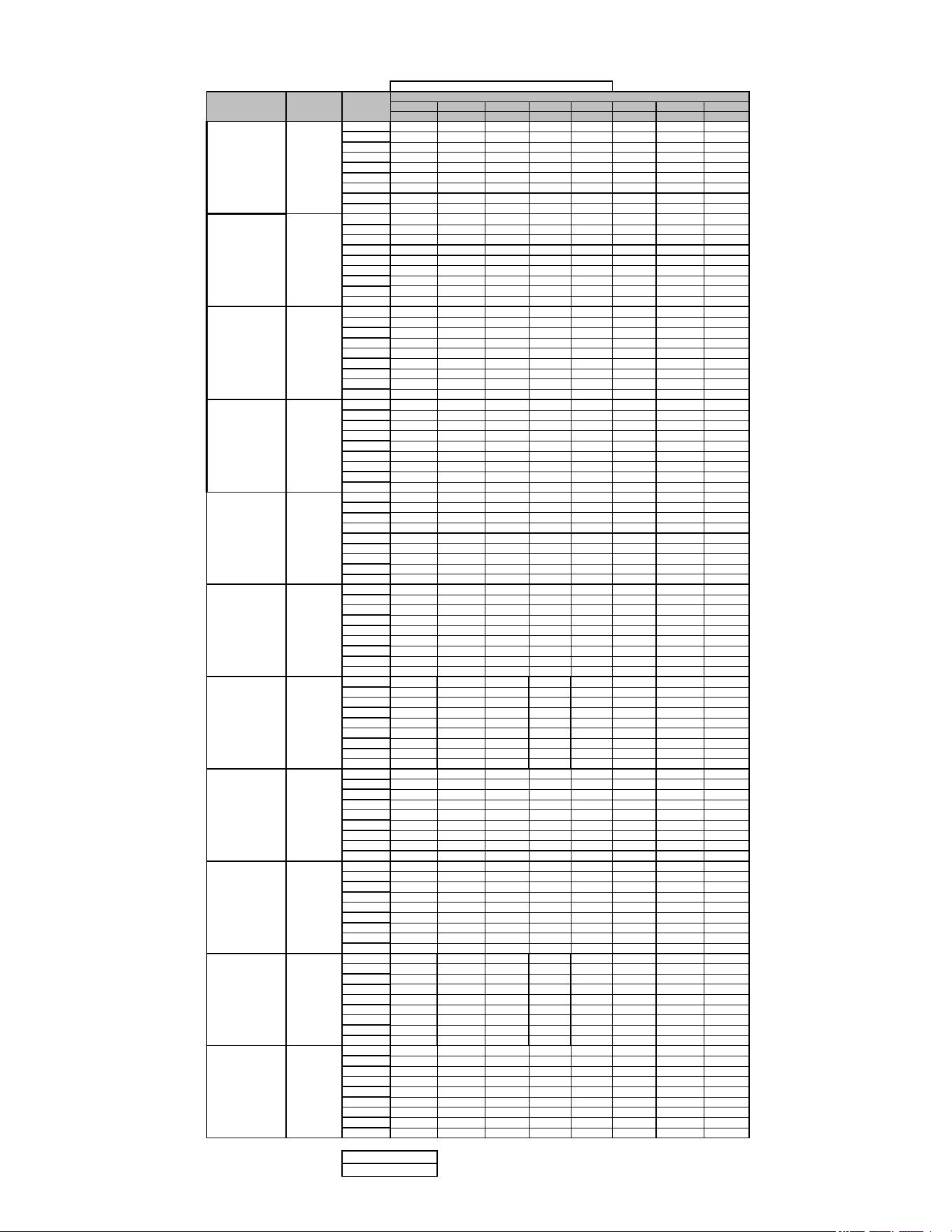
27
Airflow Tables
GM9C80
0.1 0.2 0.3 0.4 0.5 0.6 0.7 0.8
CFM CFM CFM CFM CFM CFM CFM CFM
F01
749 697 652 607 554 509 459 406
F02
1130 1090 1059 1022 991 957 926 895
F03
584 553 501 447 395 335 N/A N/A
F04
882 841 800 760 719 678 641 602
F05^
1158 1113 1090 1057 1024 996 964 935
F06
925 881 840 800 760 721 681 645
F07
1270 1235 1208 1179 1147 1119 1088 1060
F08
1330 1295 1273 1251 1223 1195 1168 1142
F09
1417 1380 1359 1336 1314 1288 1261 1238
F01 880 837 794 756 717 678 641 602
F02
1268 1221 1188 1154 1122 1091 1060 1029
F03
659 599 542 490 437 383 320 N/A
F04
1026 982 943 906 869 834 799 765
F05^
1308 1262 1224 1197 1167 1141 1117 1089
F06
1118 1070 1033 997 963 929 896 865
F07
1087 1044 1008 973 938 905 871 841
F08
1382 1341 1311 1291 1263 1234 1206 1177
F09
1492 1448 1409 1381 1354 1332 1310 1288
F01 1125 1089 1052 1013 973 947 909 863
F02
1413 1386 1360 1330 1302 1270 1242 1211
F03
720 660 614 542 468 413 359 313
F04
1146 1113 1076 1039 1002 969 933 891
F05^
1370 1345 1317 1286 1260 1224 1187 1168
F06
922 872 830 786 736 683 616 565
F07
1252 1198 1153 1110 1069 1028 990 953
F08
1289 1260 1232 1194 1161 1125 1087 1073
F09
1544 1500 1459 1419 1387 1349 1317 1286
F01 1036 985 940 895 848 799 751 705
F02
1391 1352 1314 1278 1241 1209 1175 1140
F03
710 646 580 515 432 367 314 274
F04
1138 1091 1045 1001 959 920 876 832
F05^
1209 1166 1124 1083 1045 1005 964 923
F06
977 931 880 836 785 734 683 626
F07
1298 1255 1216 1178 1140 1102 1067 1028
F08
1456 1414 1376 1341 1302 1270 1238 1200
F09
1533 1488 1452 1415 1383 1350 1317 1286
F01
1104 1056 1010 968 925 880 831 784
F02
1395 1347 1309 1270 1233 1199 1164 1125
F03
841 657 595 522 439 367 315 N/A
F04
1311 1267 1226 1189 1150 1114 1072 1034
F05^
1490 1447 1407 1373 1336 1303 1269 1237
F06
1553 1510 1469 1435 1401 1368 1335 1300
F07
1776 1735 1695 1661 1628 1601 1570 1542
F08
1593 1548 1508 1474 1440 1409 1376 1343
F09
1853 1812 1773 1739 1708 1679 1650 1623
F01
1214 1158 1103 1045 989 936 883 823
F02
1518 1465 1418 1372 1328 1284 1237 1195
F03
831 750 671 588 501 405 348 300
F04
1303 1249 1191 1136 1081 1028 974 928
F05^
1588 1539 1494 1447 1401 1358 1313 1267
F06
1426 1375 1324 1277 1229 1177 1124 1078
F07
1785 1751 1717 1675 1639 1596 1557 1516
F08
1710 1666 1632 1595 1554 1512 1473 1431
F09
1845 1805 1771 1733 1695 1655 1618 1576
F01
1420 1359 1301 1254 1206 1152 1100 1044
F02
1825 1769 1718 1673 1629 1584 1540 1497
F03
826 744 661 573 485 399 339 N/A
F04
1623 1567 1516 1468 1423 1374 1328 1281
F05^
1697 1644 1596 1551 1505 1457 1413 1367
F06
1741 1686 1639 1592 1550 1504 1462 1417
F07
1906 1855 1809 1763 1722 1682 1641 1597
F08
1966 1914 1869 1825 1782 1745 1703 1660
F09
2201 2152 2107 2073 2034 1996 1962 1925
F01
1175 1109 1044 977 905 830 750 681
F02
1828 1778 1731 1687 1643 1597 1556 1512
F03
972 899 822 741 659 574 503 438
F04
1401 1338 1290 1234 1179 1126 1073 1014
F05^
1627 1574 1526 1479 1428 1370 1326 1285
F06
1863 1810 1772 1726 1683 1638 1596 1547
F07
1920 1873 1835 1795 1751 1704 1673 1633
F08
2026 1980 1932 1894 1852 1816 1777 1737
F09
2183 2140 2095 2057 2020 1978 1947 1917
F01
1405 1356 1308 1262 1210 1155 1102 1057
F02
1846 1807 1762 1731 1685 1646 1615 1574
F03
802 724 637 551 468 389 342 294
F04
1260 1207 1156 1103 1037 982 932 878
F05^
1811 1769 1730 1686 1649 1610 1572 1525
F06
1541 1487 1440 1395 1353 1310 1251 1203
F07
1587 1545 1494 1451 1409 1367 1316 1266
F08
1703 1659 1613 1579 1537 1495 1451 1401
F09
1892 1850 1805 1774 1735 1692 1658 1621
F01
1589 1539 1498 1459 1417 1377 1334 1293
F02
2153 2119 2073 2044 2003 1971 1939 1907
F03
1034 745 642 550 462 374 329 287
F04
1579 1525 1483 1443 1400 1358 1313 1260
F05^
1891 1843 1804 1767 1730 1698 1660 1626
F06
1824 1784 1739 1700 1667 1624 1592 1555
F07
1731 1677 1637 1600 1556 1518 1474 1439
F08
1944 1901 1864 1823 1786 1748 1719 1680
F09
2219 2175 2134 2106 2071 2039 2008 1982
F01
1355 1301 1249 1196 1142 1078 1023 970
F02
1806 1764 1729 1688 1654 1615 1578 1535
F03
851 774 692 615 535 470 411 359
F04
1154 1098 1043 983 932 874 819 755
F05^
1712 1660 1614 1580 1540 1501 1461 1417
F06
1617 1568 1525 1481 1439 1402 1354 1309
F07
1869 1816 1773 1731 1693 1661 1629 1589
F08
1947 1903 1865 1833 1802 1769 1743 1708
F09
2107 2066 2030 1996 1963 1932 1899 1867
Y2
*M9C801004C* Y2
*M9C800803B* Y2
*M9C800804B* Y2
*M9C801005C* Y2
*M9C801205D* Y2
Y2
*M9C800603B* Y2
*M9C800805C* Y2
*M9C800805D*
NOTE:
^ Default Speed
HIGH STAGE COOLING AIRFLOW
MODEL
THERMOSTAT
CALL
TAP #
EXTERNAL STATIC PRESSURE, (INCHES WATER COLUMN)
*M9C800403A* Y2
*M9C800603A*
*M9C800804C* Y2
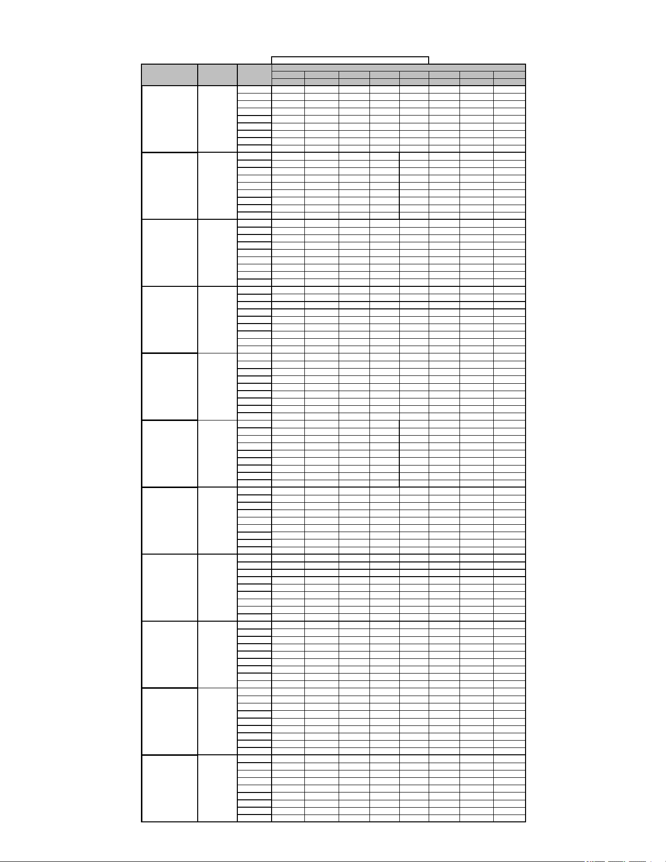
28
Airflow Tables
GM9C80
0.1 0.2 0.3 0.4 0.5 0.6 0.7 0.8
CFM CFM CFM CFM CFM CFM CFM CFM
F01
749 697 652 607 554 509 459 406
F02
1130 1090 1059 1022 991 957 926 895
F03
584 553 501 447 395 335 N/A N/A
F04
882 841 800 760 719 678 641 602
F05
1158 1113 1090 1057 1024 996 964 935
F06
925 881 840 800 760 721 681 645
F07
1270 1235 1208 1179 1147 1119 1088 1060
F08
1330 1295 1273 1251 1223 1195 1168 1142
F09
1417 1380 1359 1336 1314 1288 1261 1238
F01 880 837 794 756 717 678 641 602
F02
1268 1221 1188 1154 1122 1091 1060 1029
F03
659 599 542 490 437 383 320 N/A
F04
1026 982 943 906 869 834 799 765
F05
1308 1262 1224 1197 1167 1141 1117 1089
F06
1118 1070 1033 997 963 929 896 865
F07
1087 1044 1008 973 938 905 871 841
F08
1382 1341 1311 1291 1263 1234 1206 1177
F09
1492 1448 1409 1381 1354 1332 1310 1288
F01 1125 1089 1052 1013 973 947 909 863
F02
1413 1386 1360 1330 1302 1270 1242 1211
F03
720 660 614 542 468 413 359 313
F04
1146 1113 1076 1039 1002 969 933 891
F05
1370 1345 1317 1286 1260 1224 1187 1168
F06
922 872 830 786 736 683 616 565
F07
1252 1198 1153 1110 1069 1028 990 953
F08
1289 1260 1232 1194 1161 1125 1087 1073
F09
1544 1500 1459 1419 1387 1349 1317 1286
F01 1036 985 940 895 848 799 751 705
F02
1391 1352 1314 1278 1241 1209 1175 1140
F03
710 646 580 515 432 367 314 274
F04
1138 1091 1045 1001 959 920 876 832
F05
1209 1166 1124 1083 1045 1005 964 923
F06
977 931 880 836 785 734 683 626
F07
1298 1255 1216 1178 1140 1102 1067 1028
F08
1456 1414 1376 1341 1302 1270 1238 1200
F09
1533 1488 1452 1415 1383 1350 1317 1286
F01 1104 1056 1010 968 925 880 831 784
F02
1395 1347 1309 1270 1233 1199 1164 1125
F03
841 657 595 522 439 367 315 N/A
F04
1311 1267 1226 1189 1150 1114 1072 1034
F05
1490 1447 1407 1373 1336 1303 1269 1237
F06
1553 1510 1469 1435 1401 1368 1335 1300
F07
1776 1735 1695 1661 1628 1601 1570 1542
F08
1593 1548 1508 1474 1440 1409 1376 1343
F09
1853 1812 1773 1739 1708 1679 1650 1623
F01 1214 1158 1103 1045 989 936 883 823
F02
1518 1465 1418 1372 1328 1284 1237 1195
F03
831 750 671 588 501 405 348 300
F04
1303 1249 1191 1136 1081 1028 974 928
F05
1588 1539 1494 1447 1401 1358 1313 1267
F06
1426 1375 1324 1277 1229 1177 1124 1078
F07
1785 1751 1717 1675 1639 1596 1557 1516
F08
1710 1666 1632 1595 1554 1512 1473 1431
F09
1845 1805 1771 1733 1695 1655 1618 1576
F01 1420 1359 1301 1254 1206 1152 1100 1044
F02
1825 1769 1718 1673 1629 1584 1540 1497
F03
826 744 661 573 485 399 339 N/A
F04
1623 1567 1516 1468 1423 1374 1328 1281
F05
1697 1644 1596 1551 1505 1457 1413 1367
F06
1741 1686 1639 1592 1550 1504 1462 1417
F07
1906 1855 1809 1763 1722 1682 1641 1597
F08
1966 1914 1869 1825 1782 1745 1703 1660
F09
2201 2152 2107 2073 2034 1996 1962 1925
F01 1175 1109 1044 977 905 830 750 681
F02
1828 1778 1731 1687 1643 1597 1556 1512
F03
972 899 822 741 659 574 503 438
F04
1401 1338 1290 1234 1179 1126 1073 1014
F05
1627 1574 1526 1479 1428 1370 1326 1285
F06
1863 1810 1772 1726 1683 1638 1596 1547
F07
1920 1873 1835 1795 1751 1704 1673 1633
F08
2026 1980 1932 1894 1852 1816 1777 1737
F09
2183 2140 2095 2057 2020 1978 1947 1917
F01 1405 1356 1308 1262 1210 1155 1102 1057
F02
1846 1807 1762 1731 1685 1646 1615 1574
F03
802 724 637 551 468 389 342 294
F04
1260 1207 1156 1103 1037 982 932 878
F05
1811 1769 1730 1686 1649 1610 1572 1525
F06
1541 1487 1440 1395 1353 1310 1251 1203
F07
1587 1545 1494 1451 1409 1367 1316 1266
F08
1703 1659 1613 1579 1537 1495 1451 1401
F09
1892 1850 1805 1774 1735 1692 1658 1621
F01 1589 1539 1498 1459 1417 1377 1334 1293
F02
2153 2119 2073 2044 2003 1971 1939 1907
F03
1034 745 642 550 462 374 329 287
F04
1579 1525 1483 1443 1400 1358 1313 1260
F05
1891 1843 1804 1767 1730 1698 1660 1626
F06
1824 1784 1739 1700 1667 1624 1592 1555
F07
1731 1677 1637 1600 1556 1518 1474 1439
F08
1944 1901 1864 1823 1786 1748 1719 1680
F09
2219 2175 2134 2106 2071 2039 2008 1982
F01 1355 1301 1249 1196 1142 1078 1023 970
F02
1806 1764 1729 1688 1654 1615 1578 1535
F03
851 774 692 615 535 470 411 359
F04
1154 1098 1043 983 932 874 819 755
F05
1712 1660 1614 1580 1540 1501 1461 1417
F06
1617 1568 1525 1481 1439 1402 1354 1309
F07
1869 1816 1773 1731 1693 1661 1629 1589
F08
1947 1903 1865 1833 1802 1769 1743 1708
F09
2107 2066 2030 1996 1963 1932 1899 1867
CIRCULATION AIRFLOW
*M9C800803B* G
*M9C800804B* G
*M9C800804C* G
*M9C800805C* G
*M9C800603B* G
*M9C800805D* G
*M9C801004C* G
*M9C801005C* G
*M9C801205D* G
MODEL
THERMOSTAT
CALL
TAP #
EXTERNAL STATIC PRESSURE, (INCHES WATER COLUMN)
*M9C800403A* G
*M9C800603A* G
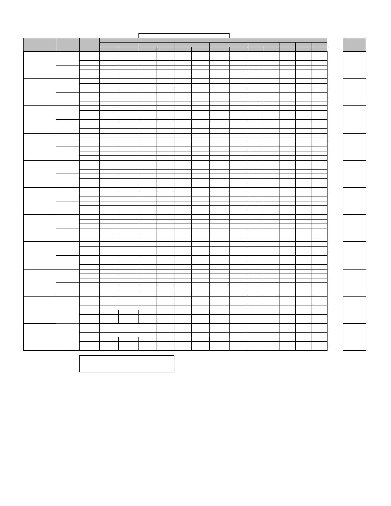
29
Airflow Tables
GM9C80
0.6 0.7 0.8
CFM RISE CFM RISE CFM RISE CFM RISE CFM RISE CFM CFM CFM
F01^ 749 28 697 30 652 32 607 34 554 37 509 459 406
F03^^ 584 N/A 553 N/A 501 N/A 447 N/A 395 N/A 335 N/A N/A
F04 882 24 841 25 800 26 760 27 719 29 678 641 602
F02^ 1130 26 1090 27 1059 28 1022 29 991 30 957 926 895
F04 882 34 841 35 800 37 760 39 719 41 678 641 602
F05
1158
26
1113
27
1090
27
1057
28
1024
29
996 964 935
F01^ 880 35 837 37 794 39 756 41 717 43 678 641 602
F03^^ 659 N/A 599 N/A 542 N/A 490 N/A 437 N/A 383 320 N/A
F04 1026 30 982 32 943 33 906 34 869 36 834 799 765
F02^ 1268 35 1221 36 1188 37 1154 38 1122 40 1091 1060 1029
F04^^ 1026 N/A 982 N/A 943 N/A 906 N/A 869 N/A 834 799 765
F05 1308 34 1262 35 1224 36 1197 37 1167 38
1141 1117 1089
F01^ 1125 28 1089 29 1052 30 1013 31 973 32 947 909 863
F03^^ 720 N/A 660 N/A 614 N/A 542 N/A 468 N/A 413 359 313
F04 1146 27 1113 28 1076 29 1039 30 1002 31 969 933 891
F02^ 1413 31 1386 32 1360 33 1330 33 1302 34 1270 1242 1211
F04 1146 39 1113 40 1076 41 1039 43 1002 44 969 933 891
F05 1370 32 1345 33 1317 34 1286 35 1260 35
1224 1187 1168
F01^ 1036 40 985 42 940 44 895 46 848 49 799 751 705
F03^^ 710 N/A 646 N/A 580 N/A 515 N/A 432 N/A 367 314 274
F04 1138 36 1091 38 1045 40 1001 41 959 43 920 876 832
F02^ 1391 43 1352 44 1314 45 1278 46 1241 48 1209 1175 1140
F04^^ 1138 N/A 1091 N/A 1045 N/A 1001 N/A 959 N/A 920 876 832
F05 1209 49 1166 51 1124 53 1083 55 1045 57
1005 964 923
F01^ 1104 38 1056 39 1010 41 968 43 925 45 880 831 784
F03^^ 841 N/A 657 N/A 595 N/A 522 N/A 439 N/A 367 315 N/A
F04 1311 32 1267 33 1226 34 1189 35 1150 36 1114 1072 1034
F02^ 1395 42 1347 44 1309 45 1270 47 1233 48 1199 1164 1125
F04 1311 45 1267 47 1226 48 1189 50 1150 52 1114 1072 1034
F05 1490 40 1447 41 1407 42 1373 43 1336 44
1303 1269 1237
F01^ 1214 34 1158 36 1103 38 1045 40 989 42 936 883 823
F03^^ 831 N/A 750 N/A 671 N/A 588 N/A 501 N/A 405 348 300
F04 1303 32 1249 33 1191 35 1136 37 1081 38 1028 974 928
F02^ 1518 39 1465 40 1418 42 1372 43 1328 45 1284 1237 1195
F04 1303 45 1249 47 1191 50 1136 52 1081 55 1028 974 928
F05 1588 37 1539 39 1494 40 1447 41 1401 42
1358 1313 1267
F01^ 1420 29 1359 31 1301 32 1254 33 1206 34 1152 1100 1044
F03^^ 826 N/A 744 N/A 661 N/A 573 N/A 485 N/A 399 339 N/A
F04^^ 1623 N/A 1567 N/A 1516 N/A 1468 N/A 1423 N/A 1374 1328 1281
F02^ 1825 32 1769 33 1718 34 1673 35 1629 36 1584 1540 1497
F04 1623 37 1567 38 1516 39 1468 40 1423 42 1374 1328 1281
F05 1697 35 1644 36 1596 37 1551 38 1505 39
1457 1413 1367
F01^ 1175 35 1109 37 1044 40 977 42 905 46 830 750 681
F03^^ 972 N/A 899 N/A 822 N/A 741 N/A 659 N/A 574 503 438
F04 1401 30 1338 31 1290 32 1234 34 1179 35 1126 1073 1014
F02^ 1828 32 1778 33 1731 34 1687 35 1643 36 1597 1556 1512
F04 1401 42 1338 44 1290 46 1234 48 1179 50 1126 1073 1014
F05 1627 36 1574 38 1526 39 1479 40 1428 41
1370 1326 1285
F01^ 1405 37 1356 38 1308 40 1262 41 1210 43 1155 1102 1057
F03^^ 802 N/A 724 N/A 637 N/A 551 N/A 468 N/A 389 342 294
F04 1260 41 1207 43 1156 45 1103 47 1037 50 982 932 878
F02^ 1846 40 1807 41 1762 42 1731 43 1685 44 1646 1615 1574
F04^^ 1260 N/A 1207 N/A 1156 N/A 1103 N/A 1037 N/A 982 932 878
F05 1811 41 1769 42 1730 43 1686 44 1649 45
1610 1572 1525
F01^ 1589 33 1539 34 1498 35 1459 36 1417 37 1377 1334 1293
F03^^ 1034 N/A 745 N/A 642 N/A 550 N/A 462 N/A 374 329 287
F04 1579 33 1525 34 1483 35 1443 36 1400 37 1358 1313 1260
F02^ 2153 34 2119 35 2073 36 2044 36 2003 37 1971 1939 1907
F04 1579 47 1525 49 1483 50 1443 51 1400 53 1358 1313 1260
F05 1891 39 1843 40 1804 41 1767 42 1730 43
1698 1660 1626
F01^ 1355 46 1301 48 1249 50 1196 52 1142 54 1078 1023 970
F03^^ 851 N/A 774 N/A 692 N/A 615 N/A 535 N/A 470 411 359
F04 1154 54 1098 57 1043 60 983 63 932 67 874 819 755
F02^ 1806 49 1764 50 1729 51 1688 53 1654 54 1615 1578 1535
F04^^ 1154 N/A 1098 N/A 1043 N/A 983 N/A 932 N/A 874 819 755
F05 1712 52 1660 54 1614 55 1580 56 1540 58
1501 1461 1417
*M9C800804C*
W/W1
W2
30 - 60
25 - 55
TEMP RANGE
15 - 45
20 - 50
15 - 45
30 - 60
EXTERNAL STATIC PRESSURE, (INCHES WATER COLUMN)
0.1
0.2
0.3
W/W1
W2
MODEL
THERMOSTAT
CALL
0.4
0.5
25 - 55
20 - 50
25 - 55
25 - 55
40 - 70*M9C801205D*
W/W1
W2
W/W1
W2
W/W1
W2
W/W1
W2
W/W1
W2
*M9C800805C*
*M9C800805D*
*M9C801004C*
*M9C801005C*
^DEFAULT & RECOMMENDED
^^NOT RECOMMENDED FOR HEATING
NOTE:
*M9C800603B*
W/W1
W2
*M9C800803B*
W/W1
W2
*M9C800804B*
W/W1
W2
HEATING AIRFLOW
TAP #
*M9C800403A*
W/W1
W2
*M9C800603A*
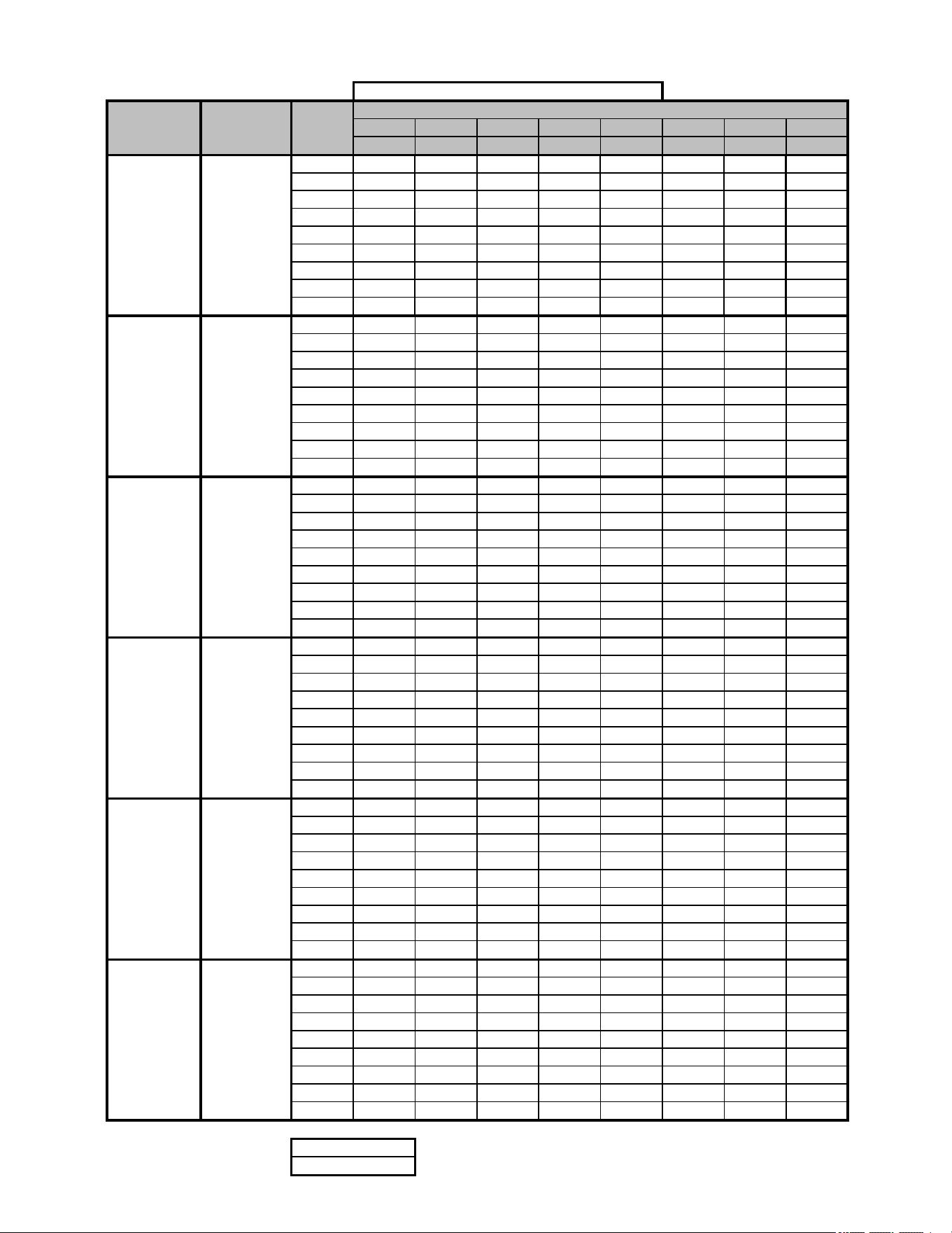
30
Airflow Tables
GC9C80
0.1 0.2 0.3 0.4 0.5 0.6 0.7 0.8
CFM CFM CFM CFM CFM CFM CFM CFM
F01 712 663 610 559 514 462 395 337
F02 1120 1081 1053 1022 990 955 918 887
F03 619 568 510 459 404 325 269 216
F04^ 825 784 741 694 650 609 563 520
F05 1000 963 930 893 852 816 776 745
F06 88 844 799 758 721 684 646 601
F07 1212 1198 1161 1138 1103 1076 1037 1007
F08 1362 1342 1307 1273 1252 1237 1211 1185
F09 1426 1405 1380 1359 1335 1312 1280 1254
F01 706 655 604 555 505 455 395 328
F02 1035 991 951 913 876 844 807 770
F03 630 572 521 466 411 341 269 216
F04^ 897 851 808 764 725 686 646 603
F05 1155 1113 1074 1039 1006 974 945 913
F06 1123 1077 1041 1006 973 941 907 875
F07 1255 1214 1181 1147 1116 1087 1056 1028
F08 1388 1331 1298 1266 1235 1207 1179 1151
F09 1421 1380 1348 1318 1289 1262 1233 1207
F01 868 811 752 692 631 510 452 399
F02 1157 1105 1058 1014 968 924 877 827
F03 738 672 598 510 413 360 309 N/A
F04^ 967 912 861 809 755 693 609 565
F05 1207 1158 1112 1065 1021 978 934 886
F06 1146 1111 1078 1041 1007 975 942 896
F07 1254 1213 1176 1137 1097 1054 1014 970
F08 1293 1264 1229 1199 1170 1138 1115 1074
F09 1394 1358 1322 1302 1267 1232 1196 1160
F01 1176 1105 1020 935 864 797 729 673
F02 1513 1459 1400 1335 1253 1182 1122 1067
F03 1022 813 674 585 511 431 334 282
F04^ 1640 1595 1540 1489 1436 1367 1307 1254
F05 1843 1786 1747 1690 1643 1575 1497 1435
F06 1580 1534 1495 1459 1429 1390 1356 1324
F07 1753 1713 1677 1642 1611 1576 1549 1518
F08 1523 1483 1438 1403 1370 1336 1299 1266
F09 1643 1599 1562 1525 1491 1462 1431 1394
F01 1176 1105 1020 935 864 797 729 673
F02 1513 1459 1400 1335 1253 1182 1122 1067
F03 1022 813 674 585 511 431 334 282
F04^ 1640 1595 1540 1489 1436 1367 1307 1254
F05 1843 1786 1747 1690 1643 1575 1497 1435
F06 1859 1819 1779 1734 1691 1641 1593 1520
F07 2028 1982 1946 1907 1861 1814 1749 1683
F08 2096 2045 2006 1974 1927 1882 1818 1765
F09 2203 2170 2138 2113 2074 2032 1990 1948
F01 1628 1571 1521 1472 1425 1380 1337 1291
F02 2159 2116 2072 2032 1992 1953 1916 1882
F03 956 777 675 587 468 377 324 296
F04^ 1561 1499 1441 1385 1336 1289 1243 1197
F05 2222 2174 2132 2090 2053 2013 1976 1944
F06 1833 1784 1735 1688 1645 1605 1562 1520
F07 1714 1659 1611 1564 1519 1473 1432 1387
F08 1926 1894 1849 1807 1764 1720 1683 1642
F09 1899 1853 1804 1761 1720 1681 1640 1602
EXTERNAL STATIC PRESSURE, (INCHES WATER COLUMN)
LOW STAGE COOLING AIRFLOW
^ Default Speed
NOTE:
Y/Y1
Y/Y1
Y/Y1
TAP #
*C9C800403A*
*C9C800603A*
Y/Y1 *C9C800603B*
*C9C800805C*
Y/Y1 *C9C801005C*
MODEL
THERMOSTAT
CALL
*C9C800804B* Y/Y1
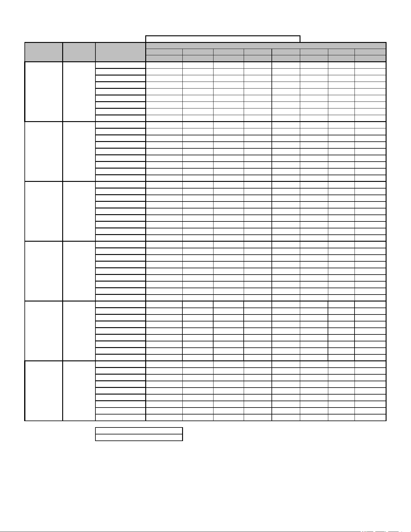
31
Airflow Tables
GC9C80
0.1 0.2 0.3 0.4 0.5 0.6 0.7 0.8
CFM CFM CFM CFM CFM CFM CFM CFM
F01
712 663 610 559 514 462 395 337
F02
1120 1081 1053 1022 990 955 918 887
F03
619 568 510 459 404 325 269 216
F04
825 784 741 694 650 609 563 520
F05^
1000 963 930 893 852 816 776 745
F06
889 844 799 758 721 684 646 601
F07
1212 1198 1161 1138 1103 1076 1037 1007
F08
1362 1342 1307 1273 1252 1237 1211 1185
F09
1426 1405 1380 1359 1335 1312 1280 1254
F01
706 655 604 555 505 455 395 328
F02
1035 991 951 913 876 844 807 770
F03
630 572 521 466 411 341 269 216
F04
897 851 808 764 725 686 646 603
F05^
1155 1113 1074 1039 1006 974 945 913
F06
1123 1077 1041 1006 973 941 907 875
F07
1255 1214 1181 1147 1116 1087 1056 1028
F08
1388 1331 1298 1266 1235 1207 1179 1151
F09
1421 1380 1348 1318 1289 1262 1233 1207
F01
868 811 752 692 631 510 452 399
F02
1157 1105 1058 1014 968 924 877 827
F03
738 672 598 510 413 360 309 N/A
F04
967 912 861 809 755 693 609 565
F05^
1207 1158 1112 1065 1021 978 934 886
F06
1146 1111 1078 1041 1007 975 942 896
F07
1254 1213 1176 1137 1097 1054 1014 970
F08
1293 1264 1229 1199 1170 1138 1115 1074
F09
1394 1358 1322 1302 1267 1232 1196 1160
F01
1176 1105 1020 935 864 797 729 673
F02
1513 1459 1400 1335 1253 1182 1122 1067
F03
1022 813 674 585 511 431 334 282
F04
1640 1595 1540 1489 1436 1367 1307 1254
F05^
1843 1786 1747 1690 1643 1575 1497 1435
F06
1580 1534 1495 1459 1429 1390 1356 1324
F07
1753 1713 1677 1642 1611 1576 1549 1518
F08
1523 1483 1438 1403 1370 1336 1299 1266
F09
1643 1599 1562 1525 1491 1462 1431 1394
F01
1176 1105 1020 935 864 797 729 673
F02
1513 1459 1400 1335 1253 1182 1122 1067
F03
1022 813 674 585 511 431 334 282
F04
1640 1595 1540 1489 1436 1367 1307 1254
F05^
1843 1786 1747 1690 1643 1575 1497 1435
F06
1859 1819 1779 1734 1691 1641 1593 1520
F07
2028 1982 1946 1907 1861 1814 1749 1683
F08
2096 2045 2006 1974 1927 1882 1818 1765
F09
2203 2170 2138 2113 2074 2032 1990 1948
F01
1628 1571 1521 1472 1425 1380 1337 1291
F02
2159 2116 2072 2032 1992 1953 1916 1882
F03
956 777 675 587 468 377 324 296
F04
1561 1499 1441 1385 1336 1289 1243 1197
F05^
2222 2174 2132 2090 2053 2013 1976 1944
F06
1833 1784 1735 1688 1645 1605 1562 1520
F07
1714 1659 1611 1564 1519 1473 1432 1387
F08
1926 1894 1849 1807 1764 1720 1683 1642
F09
1899 1853 1804 1761 1720 1681 1640 1602
HIGH STAGE COOLING AIRFLOW
TAP #
EXTERNAL STATIC PRESSURE, (INCHES WATER COLUMN)
NOTE:
^ Default Speed
*C9C800603A* Y2
*C9C800603B* Y2
MODEL
THERMOSTAT
CALL
*C9C800403A* Y2
*C9C800804B* Y2
*C9C800805C* Y2
*C9C801005C* Y2
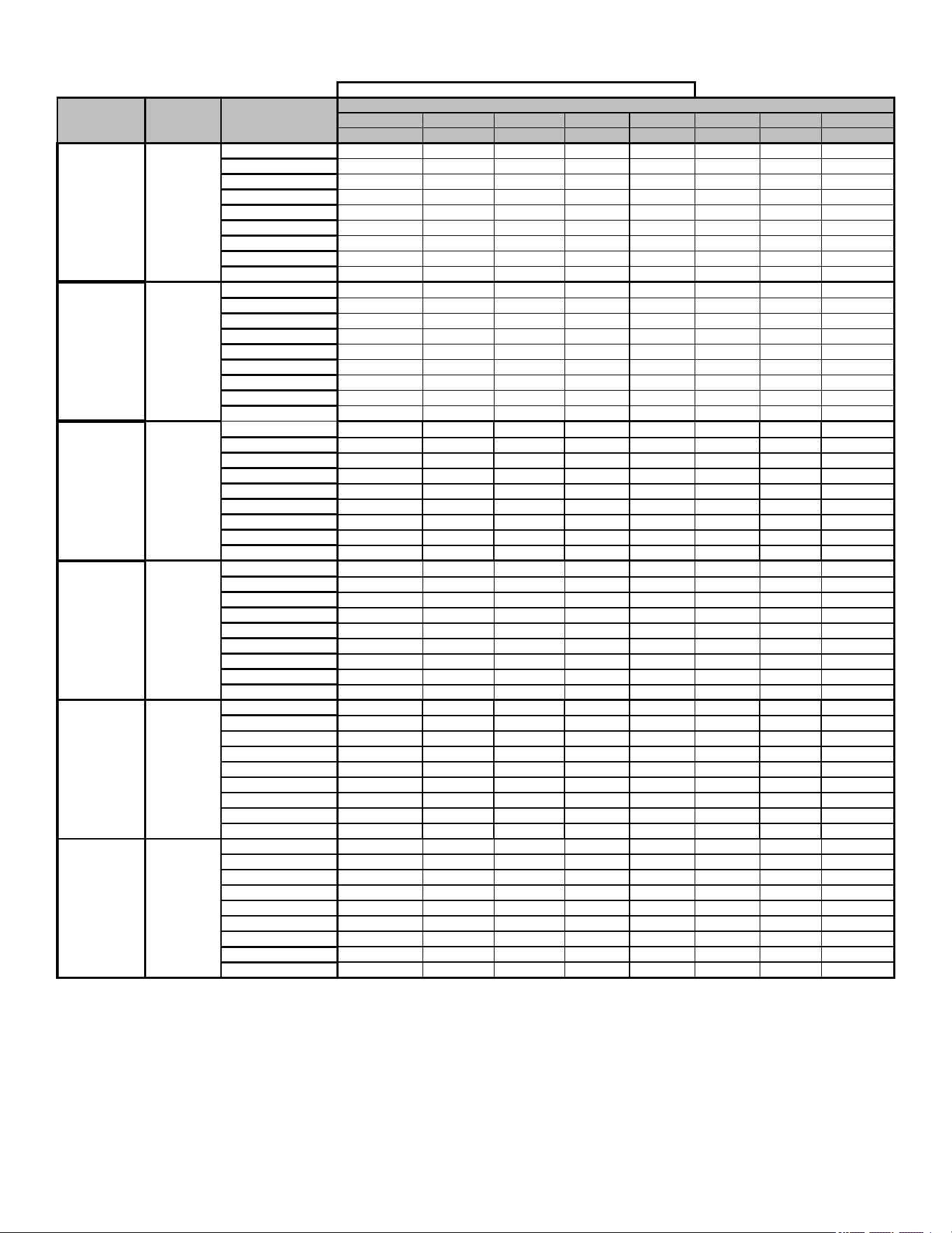
32
Airflow Tables
GC9C80
0.1 0.2 0.3 0.4 0.5 0.6 0.7 0.8
CFM CFM CFM CFM CFM CFM CFM CFM
F01
712 663 610 559 514 462 395 337
F02
1120 1081 1053 1022 990 955 918 887
F03
619 568 510 459 404 325 269 216
F04
825 784 741 694 650 609 563 520
F05
1000 963 930 893 852 816 776 745
F06
889 844 799 758 721 684 646 601
F07
1212 1198 1161 1138 1103 1076 1037 1007
F08
1362 1342 1307 1273 1252 1237 1211 1185
F09
1426 1405 1380 1359 1335 1312 1280 1254
F01
706 655 604 555 505 455 395 328
F02
1035 991 951 913 876 844 807 770
F03
630 572 521 466 411 341 269 216
F04
897 851 808 764 725 686 646 603
F05
1155 1113 1074 1039 1006 974 945 913
F06
1123 1077 1041 1006 973 941 907 875
F07
1255 1214 1181 1147 1116 1087 1056 1028
F08
1388 1331 1298 1266 1235 1207 1179 1151
F09
1421 1380 1348 1318 1289 1262 1233 1207
F01
868 811 752 692 631 510 452 399
F02
1157 1105 1058 1014 968 924 877 827
F03
738 672 598 510 413 360 309 N/A
F04
967 912 861 809 755 693 609 565
F05
1207 1158 1112 1065 1021 978 934 886
F06
1146 1111 1078 1041 1007 975 942 896
F07
1254 1213 1176 1137 1097 1054 1014 970
F08
1293 1264 1229 1199 1170 1138 1115 1074
F09
1394 1358 1322 1302 1267 1232 1196 1160
F01
1176 1105 1020 935 864 797 729 673
F02
1513 1459 1400 1335 1253 1182 1122 1067
F03
1022 813 674 585 511 431 334 282
F04
1640 1595 1540 1489 1436 1367 1307 1254
F05
1843 1786 1747 1690 1643 1575 1497 1435
F06
1580 1534 1495 1459 1429 1390 1356 1324
F07
1753 1713 1677 1642 1611 1576 1549 1518
F08
1523 1483 1438 1403 1370 1336 1299 1266
F09
1643 1599 1562 1525 1491 1462 1431 1394
F01
1176 1105 1020 935 864 797 729 673
F02
1513 1459 1400 1335 1253 1182 1122 1067
F03
1022 813 674 585 511 431 334 282
F04
1640 1595 1540 1489 1436 1367 1307 1254
F05
1843 1786 1747 1690 1643 1575 1497 1435
F06
1859 1819 1779 1734 1691 1641 1593 1520
F07
2028 1982 1946 1907 1861 1814 1749 1683
F08
2096 2045 2006 1974 1927 1882 1818 1765
F09
2203 2170 2138 2113 2074 2032 1990 1948
F01
1628 1571 1521 1472 1425 1380 1337 1291
F02
2159 2116 2072 2032 1992 1953 1916 1882
F03
956 777 675 587 468 377 324 296
F04
1561 1499 1441 1385 1336 1289 1243 1197
F05
2222 2174 2132 2090 2053 2013 1976 1944
F06
1833 1784 1735 1688 1645 1605 1562 1520
F07
1714 1659 1611 1564 1519 1473 1432 1387
F08
1926 1894 1849 1807 1764 1720 1683 1642
F09
1899 1853 1804 1761 1720 1681 1640 1602
*C9C801005C* G
*C9C800804B* G
*C9C800805C* G
*C9C800603A* G
*C9C800603B* G
MODEL
THERMOSTAT
CALL
TAP #
EXTERNAL STATIC PRESSURE, (INCHES WATER COLUMN)
*C9C800403A* G
CIRCULATION AIRFLOW
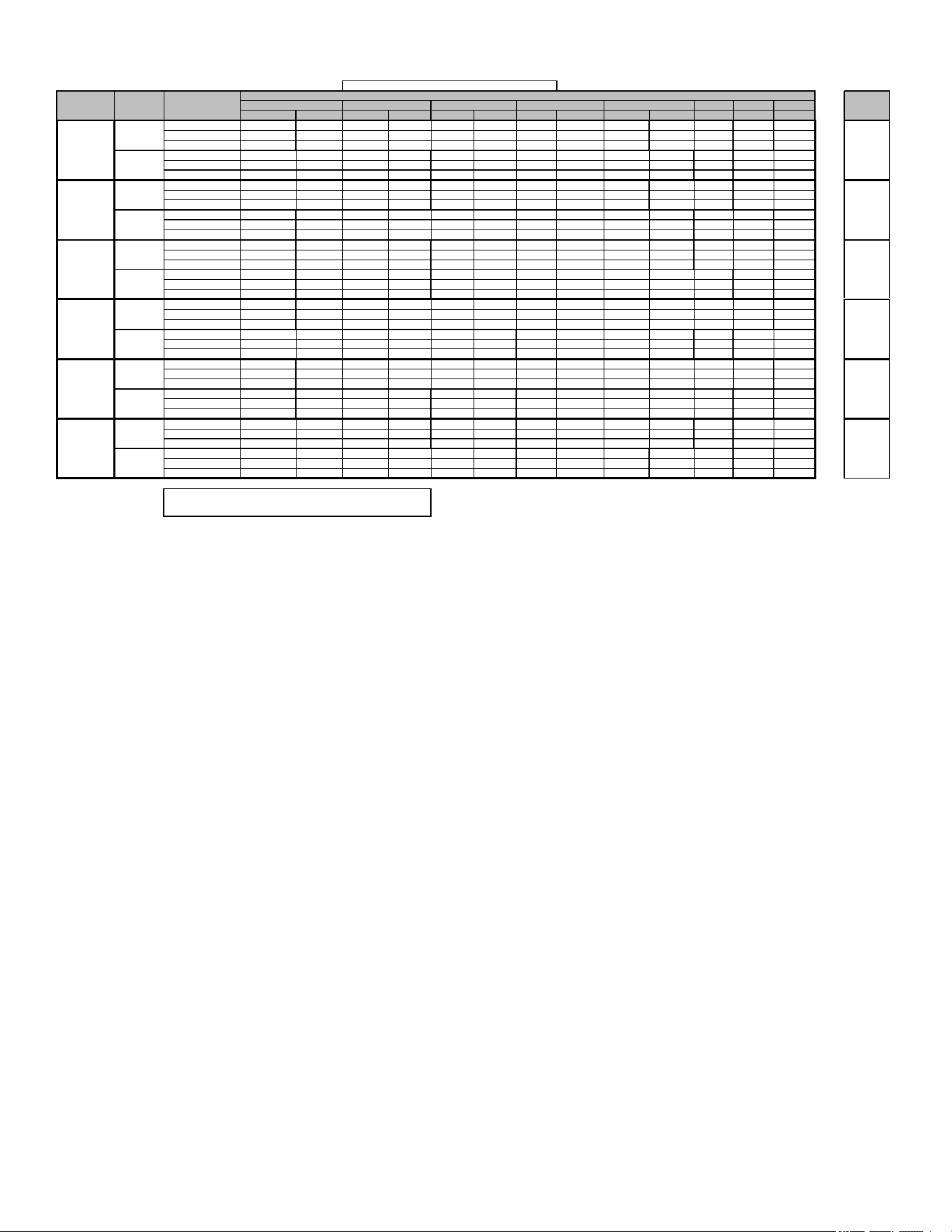
33
Airflow Tables
GC9C80
0.6 0.7 0.8
CFM RISE CFM RISE CFM RISE CFM RISE CFM RISE CFM CFM CFM
F01^ 712 29 663 31 610 34 559 37 514 40 514 395 337
F03^^ 619 N/A 568 N/A 510 N/A 459 N/A 404 N/A 325 269 216
F04 825 25 784 26 741 28 694 30 650 32 609 563 520
F02^ 1120 26 1081 27 1053 28 1022 29 990 30 955 918 887
F04 825 36 784 38 741 40 694 43 650 45 609 563 520
F05
1000
30
963
31
930
32
893
33
852
35
816 776 745
F01^ 706 44 655 48 604 52 555 56 505 59 455 395 328
F03^^ 630 N/A 572 N/A 521 N/A 466 N/A 411 N/A 341 269 216
F04 897 35 851 37 808 39 764 41 725 43 686 646 603
F02^ 1035 43 991 45 951 47 913 49 876 51 844 807 770
F04^^ 897 N/A 851 N/A 808 N/A 764 N/A 725 N/A 686 646 603
F05 1155 38 1113 40 1074 41 1039 43 1006 44
974 945 913
F01^ 868 36 811 38 752 41 692 45 631 49 510 452 399
F03^^ 738 N/A 672 N/A 598 N/A 510 N/A 413 N/A 360 309 N/A
F04 967 32 912 34 861 36 809 38 755 41 693 609 565
F02^ 1157 38 1105 40 1058 42 1014 44 968 46 924 877 827
F04 967 46 912 49 861 52 809 55 755 59 693 609 565
F05 1207 37 1158 38 1112 40 1065 42 1021 44
978 934 886
F01^ 1011 41 958 43 912 46 866 48 815 51 763 710 642
F03^^ 760 N/A 697 N/A 636 N/A 569 N/A 481 N/A 402 349 300
F04 1309 32 1261 33 1218 34 1182 35 1142 36 1103 1064 1025
F02^ 1393 43 1348 44 1308 45 1270 47 1230 48 1196 1158 1123
F04 1309 45 1261 47 1218 49 1182 50 1142 52 1103 1064 1025
F05 1459 41 1414 42 1371 43 1336 44 1297 46
1264 1229 1193
F01^ 1176 35 1105 38 1020 41 935 44 864 48 797 729 673
F03^^ 1022 N/A 813 N/A 674 N/A 585 N/A 511 N/A 431 334 282
F04^^ 1640 N/A 1595 N/A 1540 N/A 1489 N/A 1436 N/A 1367 1307 1254
F02 1513 39 1459 41 1400 42 1335 44 1253 47 1182 1122 1067
F04 1640 36 1595 37 1540 38 1489 40 1436 41 1367 1307 1254
F05 1843 32 1786 33 1747 34 1690 35 1643 36
1575 1497 1435
F01^ 1628 32 1571 33 1521 34 1472 35 1425 36 1380 1337 1291
F03^^ 956 N/A 777 N/A 675 N/A 587 N/A 468 N/A 377 324 296
F04 1561 33 1499 35 1441 36 1385 37 1336 39 1289 1243 1197
F02^ 2159 34 2116 35 2072 36 2032 36 1992 37 1953 1916 1882
F04^^ 1561 N/A 1499 N/A 1441 N/A 1385 N/A 1336 N/A 1289 1243 1197
F05 2222 33 2174 34 2132 35 2090 35 2053 36
2013 1976 1944
NOTE:
^DEFAULT & RECOMMENDED
^^NOT RECOMMENDED FOR HEATING
W/W1
W2
*C9C800804B*
15 - 45
30 - 60
30 - 60
30 - 60
TEMP RANGE
W2
30 - 60
W/W1
W2
W/W1
W2
W/W1
W2
W/W1
W2
W/W1
20 - 50
*C9C800805C*
*C9C801005C*
HEATING AIRFLOW
MODEL
THERMOSTAT
CALL
TAP #
EXTERNAL STATIC PRESSURE, (INCHES WATER COLUMN)
0.1
0.2
0.3
0.4
0.5
*C9C800403A*
*C9C800603A*
*C9C800603B*
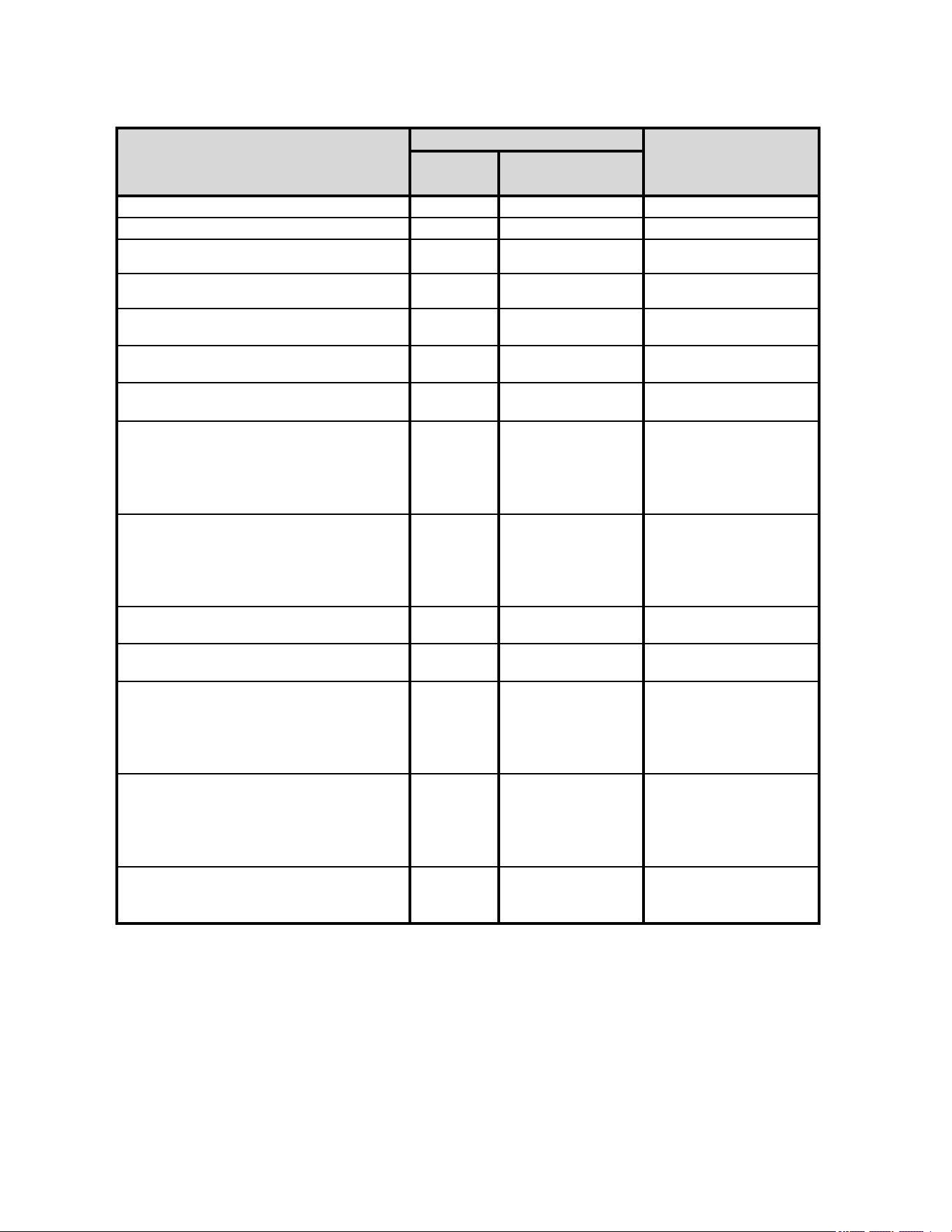
34
2 Stage Status Codes
Main Menu Option Menu
Active Alarm menu
xx
( xx: code numbers )
Last 6 Faults
xx
( xx: code numbers )
Code Release Number
CR Number
Reset to Factory Default
yes, no
Blower Speed for Continous Fan Mode
xx
( xx: Blower Speed Number
F01, F02.. )
Blower Speed for 1st Stage Compressor Mode
xx
( xx: Blower Speed Number
F01, F02.. )
Blower Speed for 2nd Stage Compressor Mode
xx
( xx: Blower Speed Number
F01, F02.. )
Cool On Delay
Delay, Seconds
Default set at 7 Secs,
Adjustments can be made in
7 Secs increments from 0 to
35 Secs
Cool Off Delay
Delay, Seconds
Default set at 65 Secs,
Adjustments can be made in
5 Secs increments from 0 to
120 Secs
Blower Speed for 1st Stage Gas Heat Mode
xx
( xx: Blower Speed Number
F01, F02.. )
Blower Speed for 2nd Stage Gas Heat Mode
xx
( xx: Blower Speed Number
F01, F02.. )
Gas Heat On Delay
Delay, Seconds
Default set at 30 Secs,
Adjustments can be made in
5 Secs increments from 5 to
30 Secs
Gas heat Off Delay
Delay, Seconds
Default set at 90 Secs,
Adjustments can be made in
30 Secs increments from 30
to 180 Secs
Automatic Heat Staging - For Two Stage Control
no, 10, 20,
30, 60, AUt
Refer to Section
"CHANGING HEATING
MODE SETTING"
Menu Description
LED Display
Notes
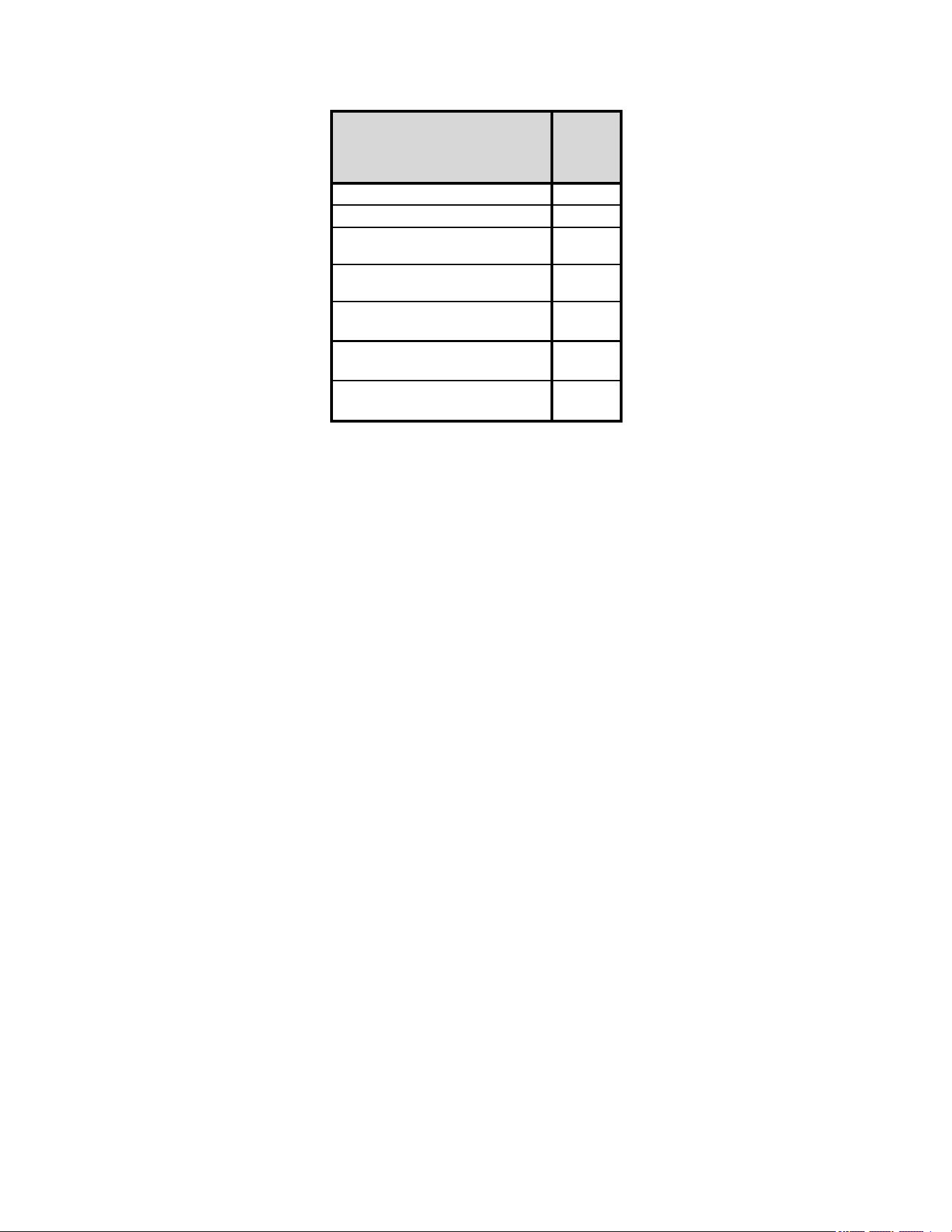
35
2 Stage Status Codes Status Menu
Idle
Continous Fan
Compressor Cooling, Low Stage
Compressor Cooling, High Stage
Gas heat, Low Stage
Gas heat, High Stage
OEM test Mode
Mode
Main
Menu
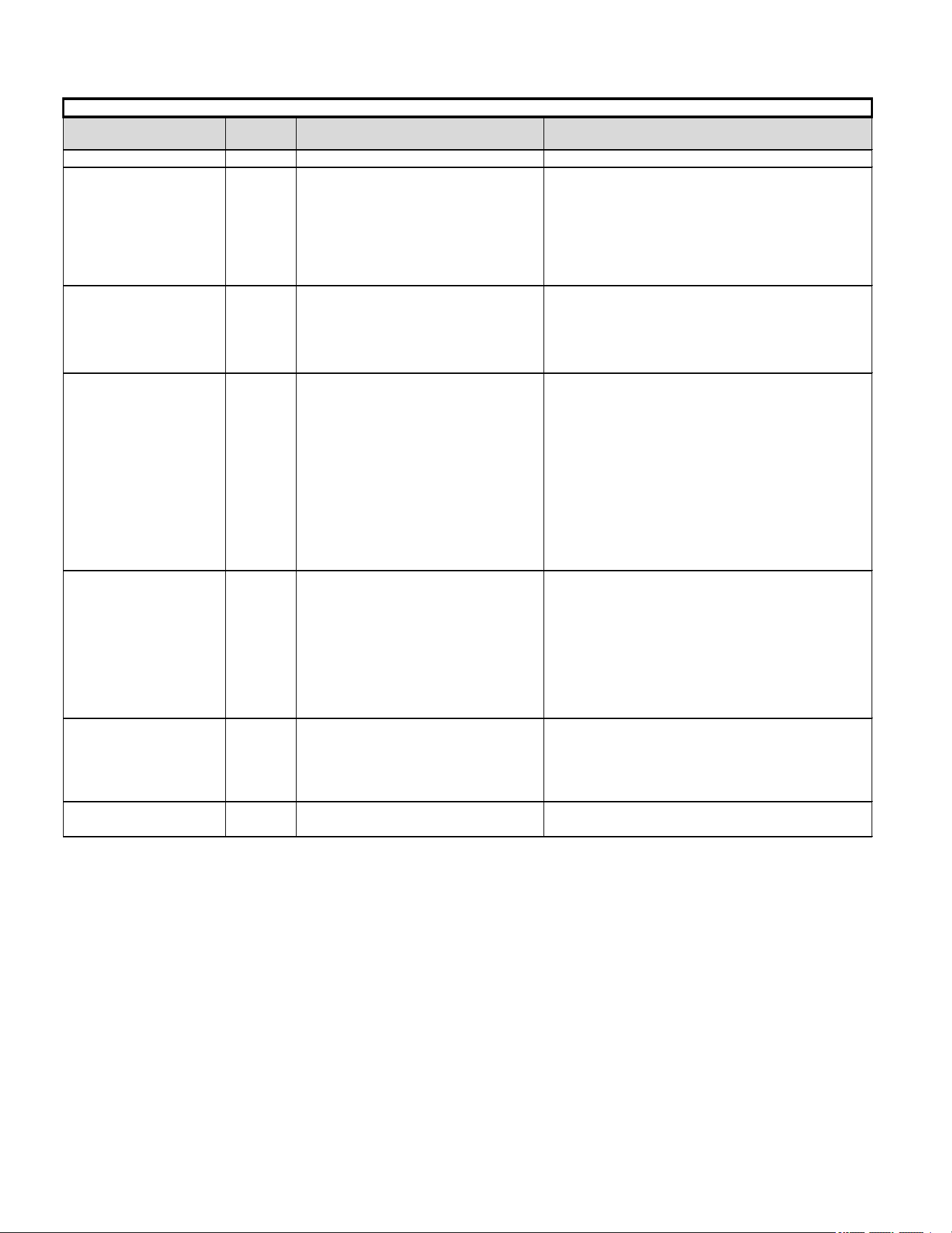
36
2 Stage Troubleshooting Codes
Symptom LED Status Fault Description Corrective Actions
Normal operation
Normal operation None
Locate and correct gas interruption
Replace or realign igniter
Check flame sense signal, clean sensor if coated or
oxidized
Check flue piping for blockage, proper length, elbows, and
termination
Verify proper induced draft blower performance
Low stage pressure switch circuit is closed at
start of heating cycle
Low stage pressure switch contacts sticking
Short in pressure switch circuit wiring
Low stage pressure switch circuit is not
closed
Pressure switch hose blocked pinched, or
connected improperly
Inspect flue for blockage, proper length, elbows, and
termination
Check induced draft blower performance, correct as
necessary
Incorrect pressure switch set point or
malfunctioning switch contacts
Check pressure switch operation, replace as needed
Loose or improperly connected wiring Tighten or correct wiring connection
Primary limit circuit is open
Check filters and ductwork for blockage Clean filters or
remove obstruction
Insufficient conditioned air over the heat
exchanger
Check circulator blower speed and performance
Blocked filters, restrictive ductwork, improper
circulator blower speed, or failed circulator
blower motor
Correct speed or replace blower motor if necessary
Loose or improperly connected wiring in high
limit circuit
Tighten or correct wiring connection
Flame sensed with no call for heat Correct short at flame sensor or in flame sensor wiring
Short to ground in flame sense circuit
Lingering burner flame Slow closing gas
valve
Open fuse Replace fuse
Short in low voltage wiring Locate and correct short in low voltage wiring
Induced draft blower and
circulator blower runs
continuously
No furnace operation
Check for lingering or lazy flame Verify proper operation of
gas valve
No furnace operation
TROUBLESHOOTING CHART
Induced draft blower runs
continuously with no furnace
operation
Inspect pressure switch hose, repair/replace if necessary
Blocked flue and/or inlet air pipe, blocked
drain system or weak induced draft blower
Replace low stage pressure switch Repair short in wiring
Circulator blower runs
continuously
No furnace operation
Furnace fails to operate
Furnace lockout due to an excessive number
of ignition “retries” (3 total)
Failure to establish flame
Loss of flame after establishment
Furnace fails to operate
To View & Clear Fault Codes
• Press either the Left or Right switch until L6F is displayed.
• Press the center switch to view stored faults.
• Press and hold the center switch for 5 to 30 seconds.
• All stored faults will be erased, and the display will ash - - - three times and return to L6F.
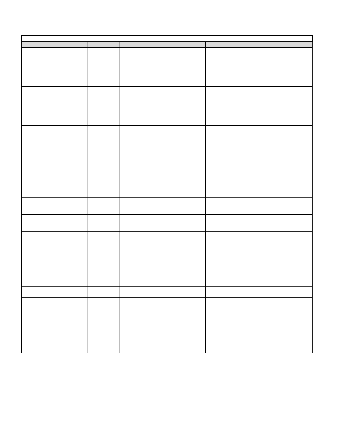
37
2 Stage Troubleshooting Codes
Symptom LED Status Fault Description Corrective Actions
Flame sense micro amp signal is minimal
Flame sensor is coated/oxidized
Flame sensor incorrectly positioned in burner
fame
Lazy burner flame due to improper gas
pressure or combustion air
Compare current gas pressure to rating plate and adjust
as needed
Problem with igniter circuit
Check and correct wiring from integrated control module
to igniter
Improperly connected or shorted igniter
Poor unit ground
Igniter relay fault on integrated control module
Check igniter output from control, replace if necessary
High stage pressure switch circuit is closed at
start of heating cycle.
High stage pressure switch contacts sticking
Shorts in pressure switch circuit wiring Repair short in wiring
Furnace fails to operate on high
stage; furnace operates normally
on low stage
Inspect pressure switch hose, repair/replace if necessary
Inspect flue and/or inlet air piping for blockage, proper
length, elbows, and termination
Check induced draft blower performance, correct as
necessary
Tighten or correct wiring connection
Polarity of 115 volt AC is reversed Correct polarity, check and correct wiring if necessary
Poor unit ground Verify proper ground, correct if necessary
Gas valve is not energized when it should be Check wiring in gas valve circuit
External Gas Valve Error Replace integrated control board
Gas valve is energized when it should not be Check wiring in gas valve circuit
Internal gas valve error Replace integrated control board
Furnace fails to operate.
No 115 power to furnace or no 24 volt power
to integrated control module.
Restore high voltage power to furnace and integrated
control module.
Blown fuse or tripped circuit breaker
Correct condition which caused fuse to open, replace
fuse
Integrated control module is non- functional
Replace non-functional integrated control module.
Furnace fails to operate
Grounding fault
Poor neutral connection
Verify neutral wire connection to furnace & continuity to
ground source
Furnace fails to operate
Open roll out switch
Check for correct gas pressure Check for correct burner
alignment
Check for and correct burner restriction
Furnace fails to operate
Ignitor Open
Check for Ignitor wiring.
Replace Damaged Ignitor
Furnace fails to operate
Inducer relay Error Replace integrated control board
Twinning feature not working
TWIN Error
Check for wiring connections.
Replace integrated control board
Furnace fails to operate
Internal Faults or IRQ Loss in Control Board Replace integrated control board
Clean flame sensor if coated or oxidized Inspect for
proper flame sensor alignment
Furnace fails to operate
Diagnose and replace shorted igniter as needed Verify
and correct unit ground wiring if needed
None
Integrated control module LED
display provides no signal
TROUBLESHOOTING CHART
Furnace fails to operate
Furnace fails to operate
Furnace fails to operate
Furnace fails to operate on high
stage; furnace operates normally
on low stage
Induced draft blower operating
Diagnose and replace high stage pressure switch if
needed
High stage pressure switch circuit is not
closed
Induced draft blower operating
Normal furnace operation
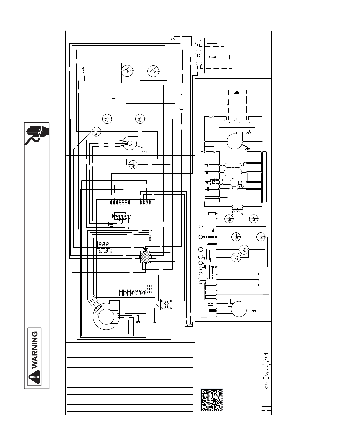
38
Wiring Diagram
HIGH VOLTAGE!
Disconnect ALL power before servicing or installing this unit. Multiple
power sources may be present. Failure to do so may cause property
damage, personal injury or death.
Wiring is subject to change. Always refer to the wiring diagram on the unit for the most up-to-date wiring.
G
N
G
N
D
R
D
GN
24
VAC
115
VAC
G
N
D
GRD
0
1
4
0
F
0
2
6
3
0
-
A
BK
E
A
C
H
U
M
I
D
I
F
I
E
R
ID
N
E
U
T
R
A
L
W
IR
IN
G
T
O
U
N
I
T
L
INTEGRATED CONTROL MODULE
H
O
T
S
U
R
F
A
C
E
G
N
D
B
L
W
R
N
E
U
T
R
A
L
W
A
R
N
I
N
G
:
G
R
O
U
N
D
E
D
.
O
V
E
R
C
U
R
R
E
N
T
P
R
O
T
E
C
T
IO
N
D
E
V
IC
E
M
U
S
T
B
E
P
R
O
P
E
R
L
Y
S
W
I
T
C
H
N
E
U
T
R
A
L
E
L
E
C
T
R
O
N
I
C
A
I
R
I
G
N
I
N
D
H
I
D
I
S
C
O
N
N
E
C
T
F
S
P
O
L
A
R
IZ
E
D
A
N
D
N
E
U
T
R
A
L
L
I
N
E
N
E
U
T
R
A
L
J
U
N
C
T
IO
N
B
O
X
B
L
W
R
I
N
D
L
O
N
I
N
D
O
O
R
A
I
R
C
L
E
A
N
E
R
H
U
M
D
O
O
R
N
E
U
T
R
A
L
INTEGRATED CONTROL MODULE
T
O
1
1
5
V
A
C
/
1
Ø
/6
0
H
Z
P
O
W
E
R
S
U
P
P
L
Y
W
IT
H
1
1
5
V
A
C
H
U
M
-
O
U
T
I
G
N
I
T
E
R
C
I
R
C
U
L
A
T
O
R
B
E
F
O
R
E
S
E
R
V
I
C
I
N
G
.
F
L
A
M
E
S
E
N
S
O
R
D
IS
C
O
N
N
E
C
T
P
O
W
E
R
L
I
N
E
G
N
D
BR
WH
GY
YL
OR
PK
RD
WH
BK
GY
L
IM
I
T
C
O
N
T
R
O
L
A
U
X
I
L
I
A
R
Y
A
U
T
O
R
E
S
E
T
P
K
W
A
R
N
I
N
G
:
D
I
S
C
O
N
N
E
C
T
40 VA
TRANSFORMER
N
N
O
G
C
S
W
I
T
C
H
P
R
E
S
S
U
R
E
L
O
W
F
IR
E
S
E
N
S
O
R
F
L
A
M
E
1
R
O
L
L
O
U
T
S
W
I
T
C
H
S
O
M
E
U
N
IT
S
M
A
Y
H
A
V
E
C
T
O
U
N
IT
M
U
S
T
B
E
P
U
BK
A
N
D
G
R
O
U
N
D
E
D
.
1
JUNCTION BOX
WH
3
BL
B
R
WH
N
O
L
I
M
IT
C
O
N
T
R
O
L
A
U
T
O
R
E
S
E
T
P
R
I
M
A
R
Y
W
H
1
W
H
L
R
D
G
Y
B
K
S
W
I
T
C
H
A
S
S
E
M
B
L
Y
ID
B
L
O
W
E
R
T
W
O
-
S
T
A
G
E
P
R
E
S
S
U
R
E
O
R
S
E
R
V
IC
IN
G
.
W
IR
IN
G
S
W
I
T
C
H
P
R
E
S
S
U
R
E
H
IG
H
F
IR
E
PK
RD
L
N
B
K
C
D
O
O
R
O
P
E
N
)
(
O
P
E
N
W
H
E
N
D
O
O
R
S
W
I
T
C
H
C
O
M
P
A
R
T
M
E
N
T
B
L
O
W
E
R
G
N
D
1
BLOWER
CIRCULATOR
OR
Ø
/6
0
H
Z
D
IS
C
O
N
N
E
C
T
(
W
H
IT
E
R
O
D
G
E
R
S
)
G
A
S
V
A
L
V
E
T
W
O
S
T
A
G
E
O
V
E
R
C
U
R
R
E
N
T
C
O
N
N
E
C
T
O
R
2
C
IR
C
U
IT
G
N
D
WH
CHASSIS
GROUND
2
3
I
G
N
I
T
E
R
S
U
R
F
A
C
E
H
O
T
2
YL
PU
2
C
B
L
O
W
E
R
D
R
A
F
T
I
N
D
U
C
E
D
PM
BK
B
L
O
W
E
R
C
O
M
P
A
R
T
M
E
N
T
1
1
5
V
A
C
/
1
BK
ECM MTR
HARNESS
HI
OR
POWER BEFORE
R
D
BK
T
O
P
O
W
E
R
S
U
P
P
L
Y
W
I
T
H
B
U
R
N
E
R
C
O
M
P
A
R
T
M
E
N
T
P
R
O
T
E
C
T
I
O
N
D
E
V
IC
E
PROPERLY PO
LARIZED
NOTES:
1. SET HEAT ANTICIPATOR ON ROOM THERMOSTAT AT 0.7 AMPS.
2. MANUFACTURER'S SPECIFIED REPLACEMENT PARTS MUST BE USED
WHEN SERVICING.
3. IF ANY OF THE ORIGINAL WIRE AS SUPPLIED WITH THE FURNACE
MUST BE REPLACED IT MUST BE REPLACED WITH WIRING MATERIAL
HAVING A TEMPERATURE RATING OF AT LEAST 105
C. USE COPPER
CONDUCTORS ONLY.
4. UNIT MUST BE PERMANENTLY GROUNDED AND CONFORM TO N.E.C.
AND LOCAL CODES.
5. TO RECALL THE LAST 6 FAULTS, MOS
T RECENT TO LEAST RECENT,
DEPRESS SWITCH FOR MORE THAN 2 SECONDS WHILE IN STANDBY
(NO THERMOSTAT INPUTS)
COLOR CODES:
PK PINK
BR BROWN
WH WHITE
BL BLUE
GY GRAY
RD RED
YL YELLOW
OR ORANGE
PU PURPLE
GN GREEN
BK BLACK
1
2
3
4
5
6
7
8
9
10
11
12
READ CODES FROM LEFT TO RIGHT
EAC-H
XFMR-H
CIRC-H
LINE-H
E20
E39
E2
E1
E15
E8
E5
E4
E3
E7
E6
E
2
5
5
E
26
W
1
4
H
U
M
-
H
K
8
1
LEFT
CENTER
RIGHT
SW
3
3
1
3
1
3
SW
1
R
2
2
3
S
W
2
6
R
2
2
6
TWIN DEHUM 24V HUM
E21
E34
E24
W2 W/W 1 R G R Y/Y1 Y2
RD
BL
RD
BR
BR
BK
BK
BK
WH
WH
WH
WH
RD
BK
YL
GY
WH
OR
GN
PU
PU
PU
PU
NEUT2
NEUT1
CIRC-N
EAC-N
HUM-N
XFMR-N
LINE-N
G
N
D
M
I
C
R
O
T
O
P
S
2
(
9
)
TR (7)
G
C
C
TH (3)
24V THERMOSTAT CONNECTIONS N.E.C. CLASS 2 WIRE
V
A
L
V
E
G
A
S
W
2
TRANS
FORMER
HLI (8)
Y
2
Y
1
R
L
O
(6
)
O
MVL (10)
NO
W
1
HI
R
M
A
N
U
A
L
R
E
S
E
T
R
O
L
L
O
U
T
L
I
M
IT
S
W
IT
C
H
H
I
G
H
F
I
R
E
P
R
E
S
S
.
S
W
T
I
C
H
.
C
L
O
W
F
I
R
E
P
R
E
S
S
S
W
IT
C
H
MVH (4)
D
E
H
U
M
PS1(5)
A
U
T
O
R
E
S
E
T
P
R
IM
A
R
Y
L
IM
IT
2
4
V
A
C
NO
PM
MVC (11)
C
BLWR
AIR
INDOOR
CIRCULATOR
R
TO
MICRO
TO
T
O
+
V
D
C
40 VA
INTERGRATED CONTROL MODULE
RLI (12)
A
U
T
O
R
E
S
E
T
A
U
X
L
I
M
IT
HLO (1)
Internal Faults or IRQ Loss E E E
Lockout Due to Excessive Retries Recycle E E 0
Low Stage Pressure Switch Stuck Closed E E 1
Low Stage pressure Switch Open E E 2
Open High Limit Switch E E 3
Flame Detected When no Flame Should be E E 4
Open Fuse E E 5
Low Flame Signal E E 6
Ignitor Relay Fault E E L
High Stage Pressure Switch Stuck Closed E E 8
High Stage Pressure Switch Open E E 9
Reversed Line Polarity or Grounding Error E E A
Internal Gas Valve Error E E b
External Gas Valve Error E E C
Open Rollout Switch E 1 1
ignitor Open E E N
Inducer Relay Error E E j
Twin Error E E H
Grounding Error E 1 0
Seven Segment Display
Status
Seg#3 Seg#2 Seg#1
5
3 41 2
R
D
B
K
O
R
B
L
Y
L
R
D
B
L
O
R
B
K
Y
L
T
1
T
2
T
3
T
4
T
5
C
O
M
R
D
SWITCH (PRESS.)
FIELD SPLICE
FIELD GND
EQUIPMENT G
ND
INTERNAL TO
PROT. DEVICE
INTEGRATED CONTROL
PLUG CONNE
CTION
SWITCH (TEMP.)
JUNCTION
LOW VOLTAGE (24V)
OVERCURRENT
TERMINAL
IGNITER
LOW VOLTAGE FIELD
HI VOLTAGE (115V)
HI VOLTAGE FIELD
39
Maintenance
WARNING
To avoid electric shock, injury or death, discon-
nect electrical power before performing any
maintanence. If you must handle the igniter, handle
with care. Touching the igniter element with bare
fingers, rough handling or vibration could damage
the igniter resulting in premature failure. Only a
qualified servicer should ever handle the igniter.
Annual Inspection
The furnace should be inspected by a qualied installer, or
service agency at least once per year. This check should be
performed at the beginning of the heating season. This will
ensure that all furnace components are in proper working or-
der and that the heating system functions appropriately. Pay
particular attention to the following items. Repair or service
as necessary.
• Flue pipe system. Check for blockage and/or leakage.
Check the outside termination and the connections at
and internal to the furnace.
• Heat exchanger. Check for corrosion and/or buildup
within the heat exchanger passageways.
• Burners. Check for proper ignition, burner ame, and
ame signal.
• Wiring. Check electrical connections for tightness and/
or corrosion. Check wires for damage.
• Filters.
Filters
CAUTION
To ensure proper unit performance, adhere to the filter
sizes given in the recommended Minimum Filter Size Table or
Specification Sheet applicable to your model.
Filter Maintenance
Improper lter maintenance is the most common cause of in-
adequate heating or cooling performance. Filters should be
cleaned (permanent) or replaced (disposable) as required.
Filter Removal
Depending on the installation, diering lter arrangements
can be applied. Filters can be installed in either the cen-
tral return register or a side panel external lter rack (upow
only). A media air lter or electronic air cleaner can be used
as an alternate lter. Follow the lter sizes given in the Rec-
ommended Minimum Filter size table to ensure proper unit
performance.
To remove lters from an external lter rack in an upright up-
ow installation, follow the directions provided with external
lter rack kit.
Horizontal Unit Filter Removal
Filters in horizontal installations are located in the central
return register or the ductwork near the furnace.
To remove:
1. Turn OFF electrical power to furnace.
2. Remove filter(s) from the central return register or
ductwork.
3. Replace lter(s) by reversing the procedure for removal.
4. Turn ON electrical power to furnace.
Media Air Filter or Electronic
Air Cleaner Removal
Follow the manufacturer’s directions for service.
Burners
Visually inspect the burner ames periodically during the
heating season. Turn on the furnace at the thermostat and
allow several minutes for ames to stabilize, since any dis-
lodged dust will alter the ames normal appearance. Flames
should be stable, quiet, soft, and blue (dust may cause or-
ange tips but they must not be yellow). They should extend
directly outward from the burners without curling, oating, or
lifting o. Flames must not impinge on the sides of the heat
exchanger ring tubes.
Induced Draft and Circulator Blowers
The bearings in the induced draft blower and circulator blow-
er motors are permanently lubricated by the manufacturer.
No further lubrication is required. Check motor windings for
accumulation of dust which may cause overheating. Clean
as necessary.
Flame Sensor (Qualified Servicer Only)
Under some conditions, the fuel or air supply can create a
nearly invisible coating on the ame sensor. This coating
acts as an insulator causing a drop in the ame sense sig-
nal. If the ame sense signal drops too low the furnace will
not sense ame and will lock out. The ame sensor should
be carefully cleaned by a qualied servicer using steel wool.
Following cleaning, the ame sense signal should be as in-
dicated in the Specications Sheet.
Flue Passages (Qualified Servicer Only)
The heat exchanger ue passageways should be inspected
at the beginning of each heating season.

40
Before Leaving an Installation
• Cycle the furnace with the thermostat at least three
times. Verify cooling and fan only operation.
• Review the Owner’s Manual with the homeowner and
discuss proper furnace operation and maintenance.
• Leave literature packet near furnace.
Repair and Replacement Parts
• When ordering any of the listed functional parts, be sure
to provide the furnace model, manufacturing, and serial
numbers with the order.
• Although only functional parts are shown in the parts
list, all sheet metal parts, doors, etc. may be ordered
by description.
• Parts are available from your distributor.
Functional Parts List
Gas Valve Blower Motor
Gas Manifold Blower Wheel
Natural Gas Orice Blower Mounting Bracket
Propane Gas Orice Blower Cuto
Igniter Blower Housing
Flame Sensor Inductor
Rollout Limit Switch Heat Exchanger
Primary Limit Switch Auxiliary Limit Switch
Pressure Switch Integrated Control Module
Induced Draft Blower Transformer
Door Switch
41
Furnace
ELECTRICAL
Line Voltage (Measure L1 to N and N to Ground Voltage) L - N
N - G
Secondary Voltage (Measure Transformer Output Voltage) R - C
Blower Amps
BLOWER EXTERNAL STATIC PRESSURE
Return Air Static Pressure IN. W.C.
Supply Air Static Pressure IN. W.C.
Total External Static Pressure (Ignoring +/- from the reading above, add total here) IN. W.C.
TEMPERATURES
Return Air Temperature (Dry bulb / Wet bulb) DB °F WB °F
DB °F WB °F
Heating Supply Air Temperature DB °F
Temperature Rise DB °F
Delta T (Difference between Supply and Return Temperatures) DB °F
GAS PRESSURES
Gas Inlet Pressure IN. W.C.
Gas Manifold Pressure (Low Fire) IN. W.C.
Gas Manifold Pressure (High Fire) IN. W.C.
Gas Type (NG) = Natural Gas / (LP) = Liquid Propane
Additional Checks
Check wire routings for any rubbing
Check for kinked pressure switch tubing.
Check flue elbow for alignment and clamp tightness.
Check screw tightness on blower wheel.
Check factory wiring and wire connections.
Check product for proper clearances as noted by installtion instructions
°F to °C formula: (°F - 32) divided by 1.8 = °C °C to °F formula: (°C multiplied by 1.8) + 32 = °F
Model Number
Serial Number
Cooling Supply Air Temperature (Dry bulb / Wet bulb)

42
THIS PAGE IS LEFT INTENTIONALLY BLANK.

43
THIS PAGE IS LEFT INTENTIONALLY BLANK.
44
GOODMAN® BRAND
AMANA® BRAND
CUSTOMER FEEDBACK
We are very interested in all product comments.
Please ll out the feedback on one of the following links:
Goodman® Brand Products: (http://www.goodmanmfg.com/about/contact-us).
Amana® Brand Products: (http://www.amana-hac.com/about-us/contact-us).
You can also scan the QR code on the right for the product brand
you purchased to be directed to the feedback page.
GOODMAN® BRAND
AMANA® BRAND
Product Registration
Thank you for your recent purchase. Though not required to get the protection of
the standard warranty, registering your product is a relatively short process, and
entitles you to additional warranty protection, except that failure by California ad Quebec
residents to register their product does not diminish their warranty rights.
For Product Registration please register by following this link:
Goodman® Brand Products: (https://www.goodmanmfg.com/product-registration).
Amana® Brand Products: (http://www.amana-hac.com/product-registration).
You can also scan the QR code on the right to be directed to the Product Registration Page.
Our continuing commitment to quality products may mean a change in specications without notice.
© 2021 Goodman Manufacturing Company, L.P.
19001 Kermier Rd., Waller, TX 77484
www.goodmanmfg.com • www.amana-hac.com