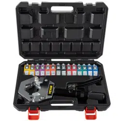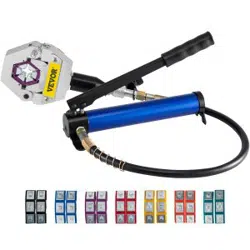
Instruction of Pipe Bender
(Integral-unit SWG series)

8. Put the lock cap (NO.18) into the inner hole of vat plug. fasten the lock-cap and
connect with the vat pipe. Then put the inner lock-cap into the big lock-cap fasten.
Note: above 7 steps the contour of bender will be finished.
9. Mount the front wheel rack (NO.16) and front wheel (NO.15) to the down wing
(NO.17), then fixed the vat plug (NO.8) with four hex-caps.
10. Mount the back wheel rack (NO.27) and front wheel (NO.26) to the below of the pump
body.
11. Set up the up wing (NO.10) to the vat plug (NO.8) then insert the wing plug (NO.9)
and insert the plug of sustain rack (NO.14) to the hole of mould wheel (NO.13), after
blocked by block-spring, then insert into the holes of both up wing (NO.10) and down wing
(NO.17).
12. When in operating, open the oil cap of the oil jaws, check the oil
If empty or not full, please fill full the oil (L-HV15) and assemble the
13. Mould (NO.11) to the head of piston, when working please daub the lube to the
concave of mould (NO.11) and mould wheel (NO.13). Then wear the handle sleeve (NO.12)
to the handle (NO.6), Last, insert one end of the handle (NO.6) into the hole of handle rack
(NO.2), starting working then.
Technique Parameter
Hydraulic oil: L-HV15 hydraulic oil
Introduction
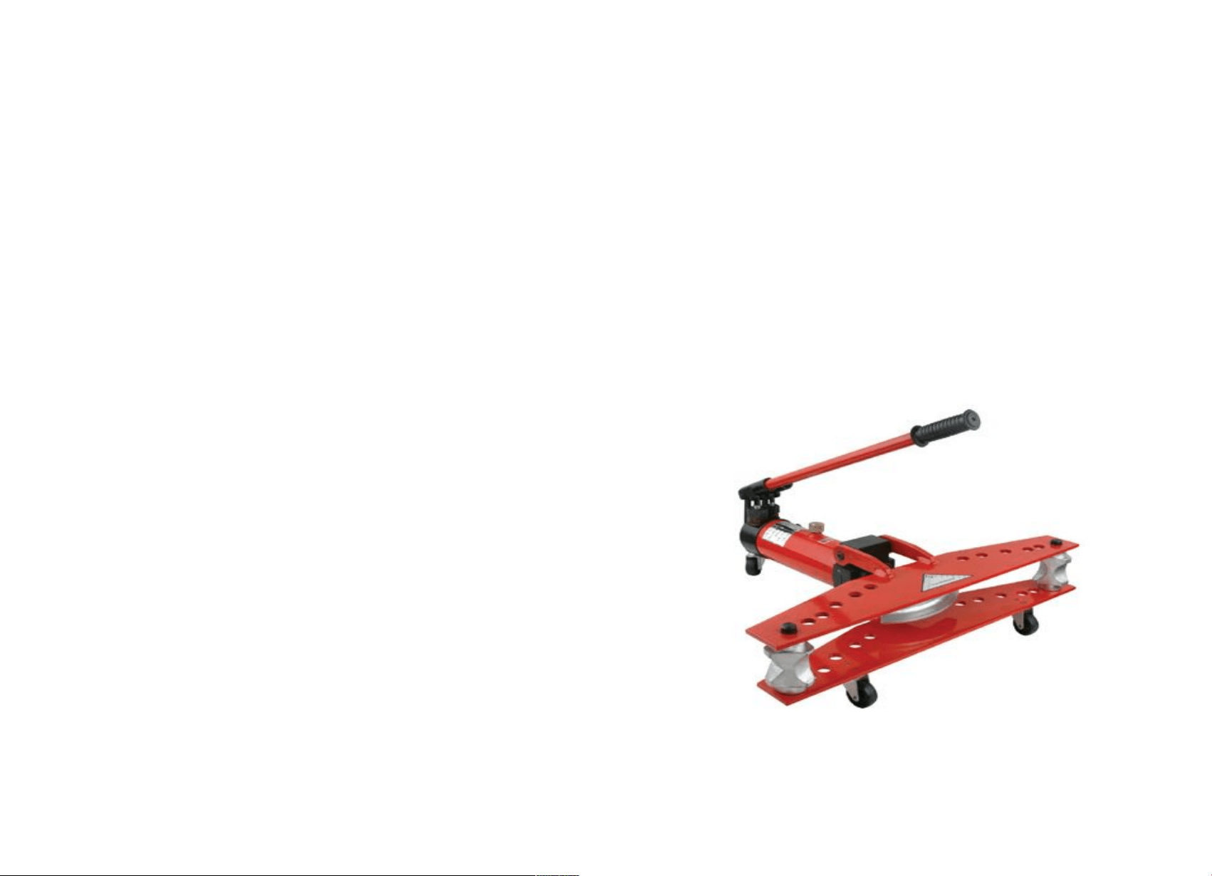
The pipe bender is suit for bending welding steel tube which has low pressure to deliver
liquid in cold situation. It is also suit for bending common water pipe; carbon steel pipe and
thick-wall conduit tube. It is not suit for bending the steel pipe with different diameter and
colored metal pipe. The machine can be use in building, Petrol, mines and shipbuilding
industry.
Working Method
1. Turn the switch tightly with clockwise direction.
2. Loosen the bolt.
3. Add lubrication on mould and the pipe.
4. Choosing corresponding mould base on size of pipe, set mould on the top of actuating
rod. Then insert the rocker on nether molding board. Put the pipe, turn two rockers and
make the groove point to the mould.
5. Turn back the upper mounding board; shake the handle of pump to make the mould press
the pipe, bending the pipe until the angle is shaped.
6. After bending. Loosen the switch anti-clockwise. The actuating rod would be back
automatically. Open the upper molding board, get out the pipe.
Attention Item
1. Diameter and the thickness of wall
Φ13 Φ16
Φ
19
Φ
22
Φ28 Φ34 Φ42
Φ
48
Φ
60
Φ
75.5
Φ89
Φ
108
Φ
114
2 2 2.5 2.75 2.75 3.25 3.25 3.5 3.5 3.75 4 4.5 5
If the thickness of steel pipe is less than the diameter number, it is called thin-wall
conduit tube. After bending the thin-wall conduit tube it would appear ruffle.
2. Before using, loosen the bolt to aerate.
3. The switch should turn tightly before bending, otherwise the pressure
could not exist in such situation.
The size of the tube must be suit for the grooves otherwise the bend pipe will
4. appear curves or splits.
5. The pipe and two rockers must be lubricity, the welding gap of pipe can not put toward
Item No
Output
(T)
Travel
(mm)
Outside Dia.
Mould
Disposition
Thickness of
Pipe(mm)
Weight
(kg)
SWG-1 10 170 Φ13mm-34mm
1/4" 5/16" 3/8" 1/2" 3/4"
1"
1-3.5 20
SWG-2 16 240 Φ22mm-60mm
1/2" 3/4" 1" 1
1
/4" 1
1
/2"
2"
2.75-4.5 44.5
SWG-3 18 320 Φ22mm-89mm
1/2" 3/4" 1" 1
1
/4" 1
1
/2"
2" 2
1
/2" 3"
2.75-6 91
SWG-4 20 380 Φ22-108mm
1/2" 3/4" 1" 1
1
/4" 1
1
/2"
2" 2
1
/2" 3" 4"
2.75-6 126.5
outside and inside of the bending part.
6. When you are working, the air may get inside of the machine. Shake the handle and
make the pump working. Get out the actuating rod, open the head of oil-vat and make the
bender in the situation angle of declining 45
。
. Then loosen the switch anti-clockwise, let the
air get out, if air is still inside, do it again and again.
7. Insert two rockers should be symmetry and make sure that they are in the right stage.
8. Costumers use our products should apply the main technique parameter. Warning that
working can not be overloaded to avoid damage.
9. The machine should be clean. The oil must be filtered clean by 200-mesh net to avoid
impurity in it.
10. It is not suitable for being used in acid, alkali and corrosive gas.
11. The pressure has been adjusted in factory, costumers do not adjust it at will.
12. If the machine finishes working, you should turn the valve switch tightly.
Instruction of assemble of bender
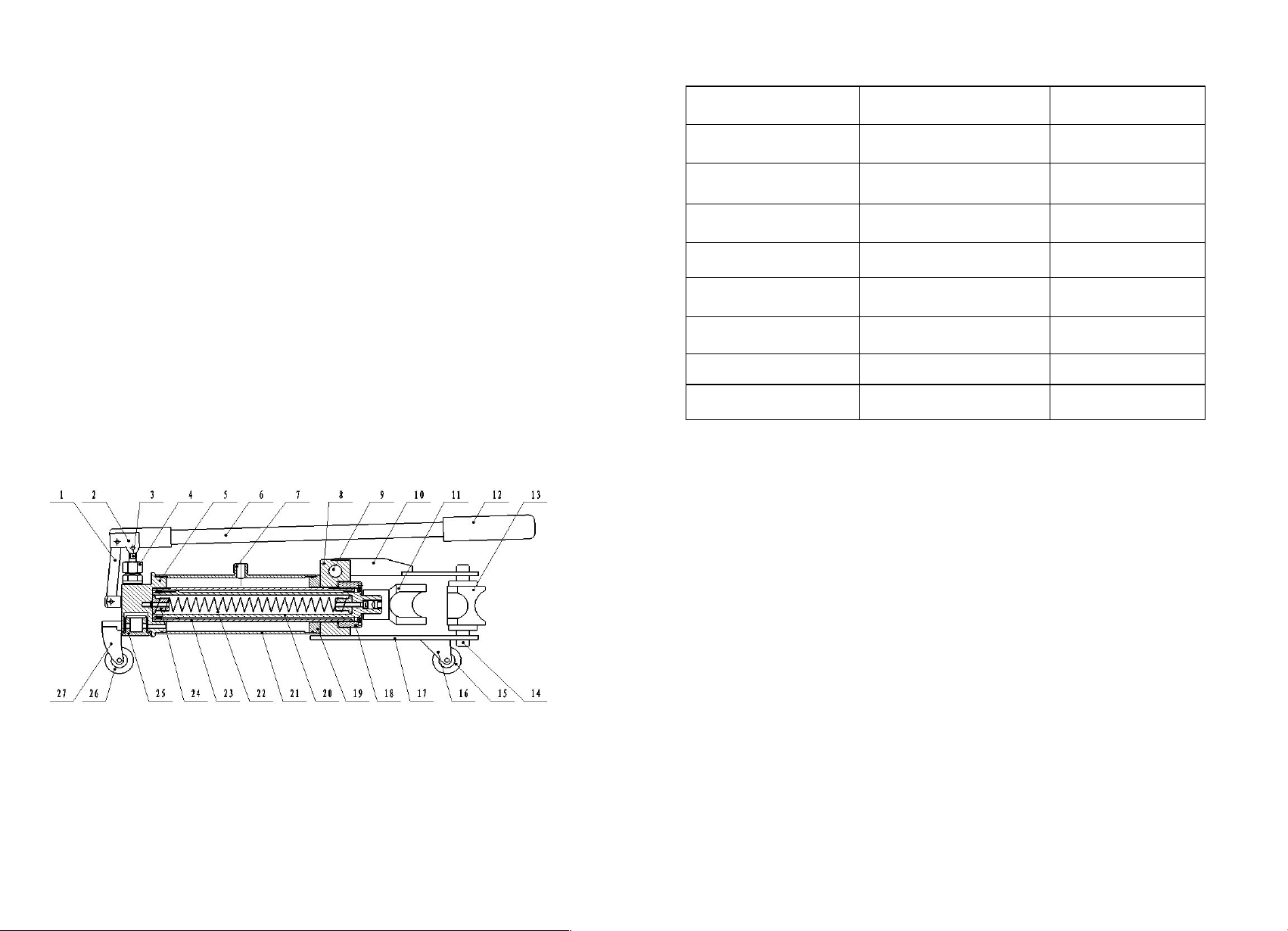
Description of the components
1: pull sheet 2.handle rack 3.pump cartridge
4:pump cover 5:pump body 6: handle
7. oil jaws 8. vat plug 9: wing plug
10. upper wing 11.bender mould 12. handle sleeve
13.mould wheel 14.plug of sustain wheel 15. front wheel
16. front wheel rack 17.down wing 18. lock cap
19. ring of press sheet 20. piston 21.outer vat pipe
22.spring 23. vat pipe 24. spring plug
25.filtration cap 26. back wheel 27. back wheel rack
1. Firstly (NO. 5) set up the steel ball, spring, valve to the head of pump. Then (NO. 3)
set up the pump cartridge and pump sleeve (NO.4). Last fitting the pull sheet (NO.1) and
handle rack (NO.2).
2. Assemble the pump body to the pliers. Put the O-Ring into pump1.
3. Body, then screw the spring which with screw cap into the pump body (NO. 22).
4. After mount the “v” type O-Ring to the O-Ring groove of big end of (NO.20) piston,
wrapping the spring outside. Meanwhile fasten the pull rod into the small end of piston.
Screw the bolt plug to the small piston.
5. Wrap the piston by pump pipe (NO.23) and screw one end fasten, put the other end
with leading- ring out of the piston but between pump pipe and piston.
6. Mount the O-Ring to the outer of pump jaws, embed the out vat pipe (NO.21) TO the
pump body, then set up the O-Ring to the ring of press sheet(NO.19)and cover the other end
of out vat pipe, forcibly so that in seal station.
7. Put the O-Ring to the tangency between ring of press sheet and vat pipe, then put the
vat plug (NO.8) onto the ring of press sheet.