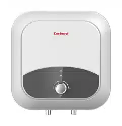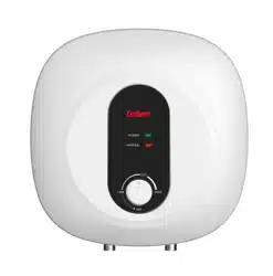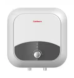

CTMVD30CM
CTMVD15CM
Termo eléctrico de almacenamiento sellado
MANUAL DE INSTRUCCIONES
1
La instalación y el mantenimiento de este aparato deben ser realizados por personal calificado
y/o técnicos autorizados por el representante de la marca.
El representante no se responsabiliza por daños y problemas de funcionamiento causados por no
cumplir las indicaciones y recomendaciones detalladas en este material.
Lea atentamente las precauciones y advertencias presentadas. No utilice este producto
para otros fines que no sean los mencionados.
CONTENIDO
TÍTULO PÁGINA
1.PRECAUCIONES............................................................................................................. 2
2.INTRODUCCIÓN DEL PRODUCTO ................................................................................ 3
3.INSTALACIÓN DE LA UNIDAD........................................................................................ 5
4.MÉTODOS DE UTILIZACIÓN.......................................................................................... 7
5.MANTENIMIENTO ........................................................................................................... 8
6.RESOLUCIÓN DE PROBLEMAS .................................................................................... 9
7.Información de product conforme la regulación UE ......................................................... 10
Observaciones generales
En caso de avería del cable de alimentación, éste deberá ser sustituido por el fabricante, su
agente de servicio o personas cualificadas del mismo tipo para evitar riesgos.
For appliance no está destinado a ser utilizado por personas (incluidos niños) con capacidades
psíquicas o mentales reducidas, o falta de experiencia y conocimiento, a menos que hayan
recibido supervisión o instrucciones sobre el uso del aparato por una persona responsable de su
seguridad.
Los niños deben ser supervisados para asegurarse de que no juegan con el aparato
Este aparato puede ser utilizado por niños a partir de 8 años y más y las personas con capaci-
dades sensorifísicas o mentales reducidas o falta de experiencia y conocimiento bajo la
condición de que se les ha dado supervisión oiinstrucción sobre el uso del aparato de una
manera segura y entender los peligros involucrados. Los niños no deberán jugar con el aparato.
Los niños no deberán realizar la limpieza y el mantenimiento sin supervisión.
●
●
●
●
2
El toma corriente eléctrico debe estar instalado y conectado a tierra de forma segura. La
corriente nominal del toma corriente no debe ser inferior a 10A. El toma corriente y el enchufe
deben permanecer secos para prevenir fugas eléctricas. Controlar frecuentemente que el
enchufe se encuentre bien conectado en el toma corriente. El método de control debe
realizarse de la siguiente manera: insertar el enchufe de abastecimiento en el toma corriente,
luego de utilizar la unidad durante media hora, apagarla y desconectar el enchufe. Controlar si
el enchufe quema al contacto con la mano. Si lo hiciera (esto sucede por encima de los 50ºC),
sirvase cambiar a otro toma corriente bien conectado a tierra para evitar que el enchufe se
dañe, si hubiese un mal contacto, podrian generarse accidentes,lesiones y/o incendios.
La altura de la instalación del toma corriente no debe ser inferior a 1,8 metros.
La pared en la cual se instale el termocalefón, deberá poder soportar el doble del peso del
calefón completamente lleno de agua sin deformaciones o grietas. De lo contrario, se deben
tomar otras medidas de refuerzo.
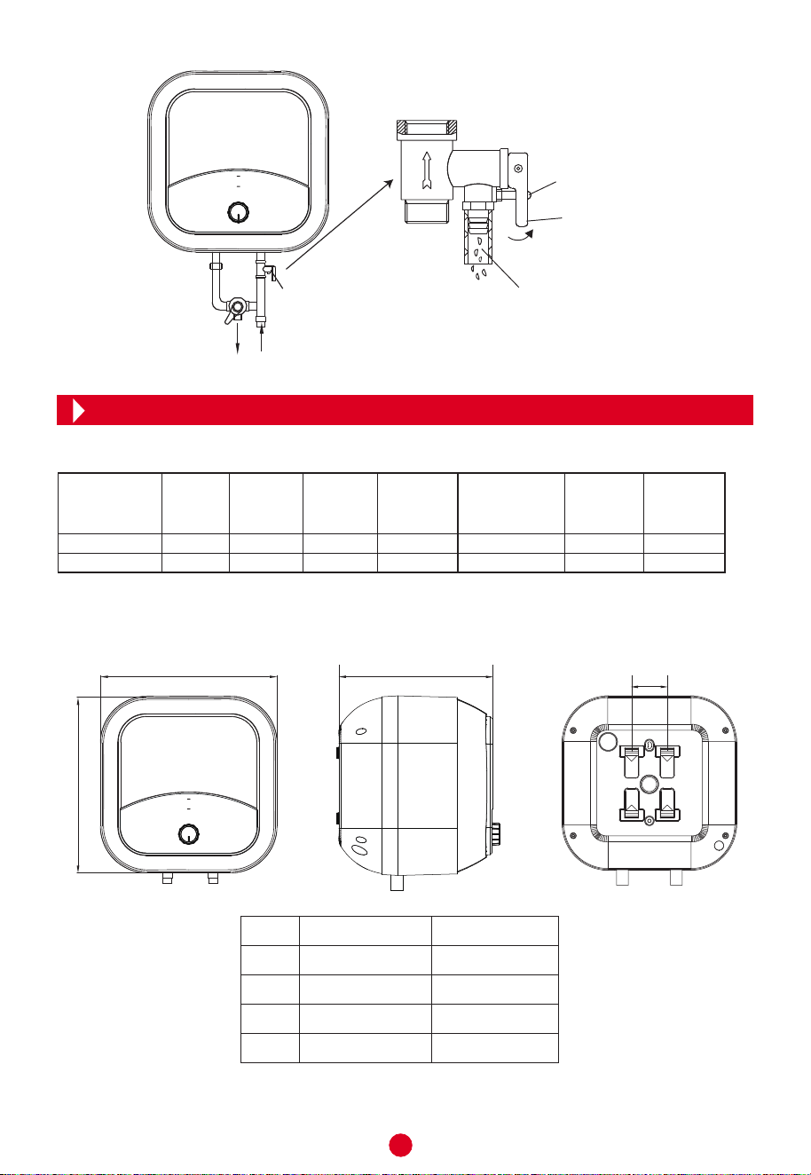
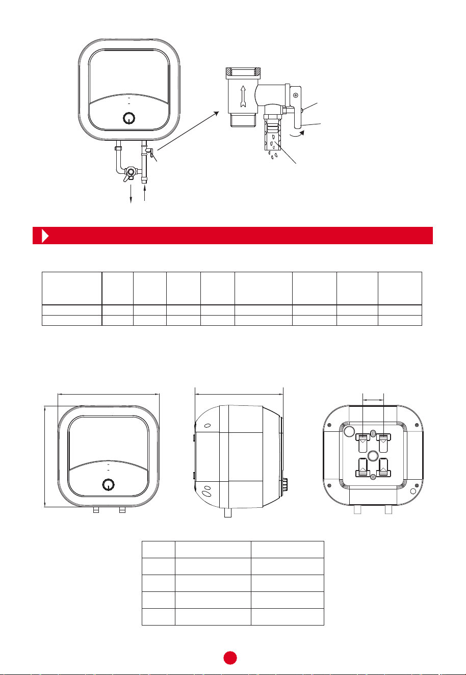
La válvula de descarga de presión que viene con el termocalefón, debe ser instalada en la
entrada de agua fria de este aparato (ver Figura 1), asegúrese de no exponerla al vapor. El
agua puede derramarse de la válvula de descarga de presión, por lo tanto el tubo de escape
debe abrirse en un costado; la válvula
de descarga de presión se debe revisar y limpiar
regularmente, de tal modo a prevenir cualquier tipo de obstrucción.
Antes de instalar este termocalefón, revisar y confirmar que la conexión a tierra del toma
corriente se encuentra instalado a tierra correctamente. De lo contrario, el producto no po-
drá ser colocado y/o utilizado. No utilizar prolongadores, adaptadores ni enchufes múltiples. Si la
la instalación no se hace de forma correcta, esto puede derivar en fallas, lesiones y daños
materiales.
Indicaciones especiales
Al utilizar el termocalefón por primera vez (o al utilizarlo por primera vez luego de realizar el
mantenimiento), el mismo no puede ser encendido hasta que haya sido llenado de agua por
completo. Al llenar el agua, al menos una de las válvulas de salida del termocalefón debe ser
abierta para liberar el aire. Esta válvula puede ser cerrada luego de que el termocalefón se
llene de agua.
El termocalefón no está diseñado para ser utilizado por personas (incluyendo niños) con
capacidades físicas, sensoriales y/o mentales reducidas o que carezcan de conocimiento
sobre el manejo del aparato, a menos que hayan sido instruidos por una persona responsa-
ble de su seguridad y sean vigilados constantemente. Los niños deben ser supervisados para
evitar que jueguen con el producto.
1. PRECAUCIONES
Durante el proceso de calentamiento, podrían caer gotas del orificio de descarga de presión
de las válvulas multifuncionales. Este es un fenómeno normal. Si hay una fuga grande de
agua, contacte con el Servicio Técnico Autorizado por el representante para la revisión. El
orificio de descarga de presión no debe ser bloqueado bajo ninguna circunstancia; de lo
contrario se pueden generar situaciones de riesgo y accidentes.
El tubo de drenaje conectado al orificio de descarga de presión se debe apuntar hacia abajo.
Ya que la temperatura del agua en el interior del termocalefón puede llegar a 65°C o 75°C de-
pendiendo del modelo, no debe ser expuesta directamente a la piel. Proceda a ajustar la tem-
peratura para evitar quemaduras.
Aflojar el tornillo de rosca en la válvula de seguridad multifuncional, y levantar la manija de
drenaje hacia arriba (ver Figura 1) para desagotar el agua del tanque interno.
Si el enchufe y/o el cable de alimentación eléctrica se dañan, deben ser reemplazados por el
Servicio Técnico Autorizado o por personal similarmente calificado. No intente desarmar ni
desmontar el aparato por cuenta propia. Ignorar esto puede ocasionar lesiones y accidentes.
No modifique ni utilice el producto para otro fin que no sea el mencionado en este material.
3
A
B
C
D
368
368
297
66
440
440
385
66
CTMVD15CM CTMVD30CM
Agua caliente
Agua fría
Válvula de descarga
de presión
Tornillo de rosca
Manija de drenaje
Orificio de descarga
Figura 1
CTMVD15CM
CTMVD30CM
2.2 Medidas y dimensiones
Tensión
Nominal
(V)
IPX4750.75220-240150015
Potencia
Nominal
(W)
Volumen
(L)
Presión
Nominal
(MPa)
Temperatura
máxima de agua
(°C)
Clasifica-
ción
Eléctrica
Grado de
impermea-
bilidad
2.1 Especificaciones técnicas
I
IPX4750.75220-240150030
I
Modelo
2. INTRODUCCIÓN DEL PRODUCTO
Nota: Todas las dimensiones están en mm
C
A
B
D
4
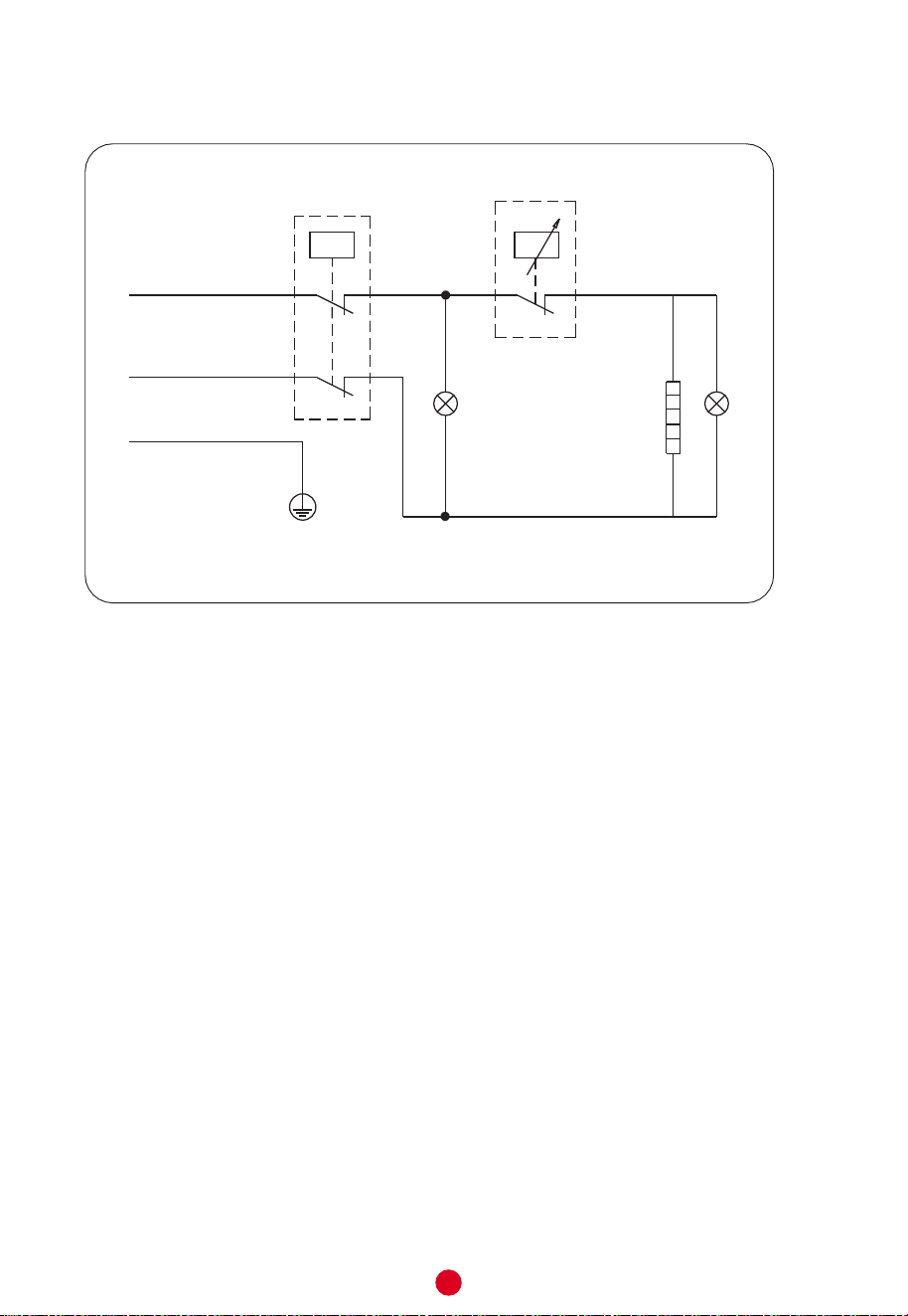
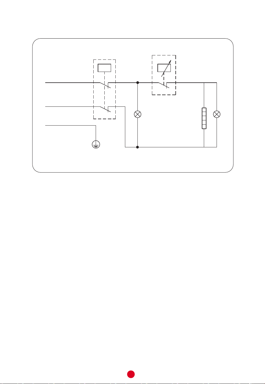
2.3 Diagrama eléctrico
ESQUEMA DE CONEXIÓN
Calentador eléctrico
Luz indicadora de
calentamiento
Apagado
Térmico
Termostato
Marrón
Azul
Amarillo/verde
E
N
L
Q
Q
Indicador de
encendido
5
3.2 Conexiones de mangueras y tuberías
3.1 Instrucciones de instalación
5
Este termocalefón eléctrico debe ser instalado en una pared firme, sólida y nivelada que
pueda soportar la carga igual a dos veces el peso del termocalefón totalmente lleno de
agua. Si fuera necesario se puede emplear un soporte reforzado.
En caso de que la pared tenga ladrillos huecos, asegurarse de llenarlos por completo con
cemento antes de colocar el aparato.
Si el baño es muy pequeño, el termocalefón puede ser colocado en otro lugar donde no se
encuentre expuesto a la luz solar directa y/o a la lluvia. Tenga en cuenta que para reducir la pérdida
de calor a través de los tubos y mangueras, el termocalefón debe instalarse lo más cerca posible
de donde se vaya a utilizar el agua caliente.
La dimensión de cada manguera es de G1/2”; para medir la presión (tanto de entrada y
de salida) se debe utilizar la unidad Pa (Pascal), respetando los valores requeridos.
La conexión de la válvula de descarga de presión del termocalefón debe realizarse en
la entrada de agua fría.
Para evitar pérdidas al conectar la mangueras, coloque las juntas y anillos de goma en
cada uno de los extremos roscados. Ignorar esto ocasionará fugas de agua y filtraciones
(ver Figura 5).
Los requisitos de alimentación eléctrica son los siguientes: 220V - 240V 50/60Hz (monó-
fásica) de tres electrodos. Es recomendable colocar la toma de corriente a la derecha por
encima del termocalefón. La altura de la toma de corriente al suelo no debe ser menor de
1,8 metros (ver la Figura 4).
Figura 4
3. INSTALAClÓN DE LA UNIDAD
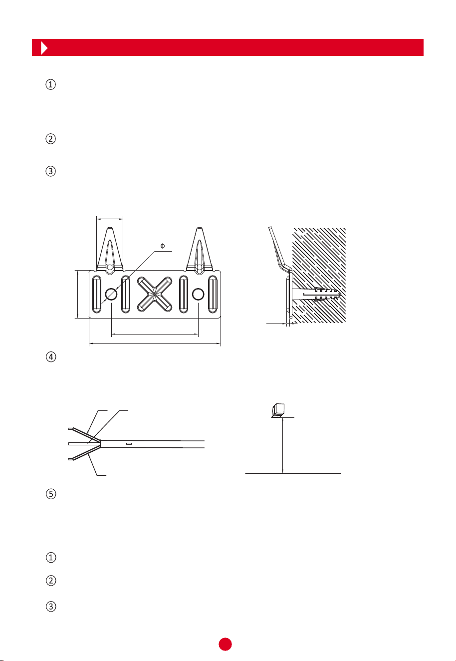
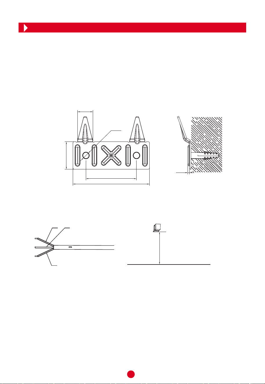
Después de seleccionar una ubicación adecuada, coloque el soporte en la pared. Siga los
pasos mostrados. La fijación debe hacerse empleando tornillos y tarugos como se muestra
en la Figura 3. La apariencia del soporte es la que aparece en la Figura 2.
Alinee las ranuras en la parte trasera del termocalefón con las 2 pestañas metálicas del
soporte y proceda a fijar el producto. Compruebe que la colocación se ha completado in-
tentando mover el calefón.
Figura 2 Figura 3
100
36
20
66
2- 8.5
2.2
≥1.8m
Suelo
L (Marrón)
E (Amarillo/verde)
N (Azul)
6
NOTA
Asegúrese de utilizar los accesorios y componentes proveídos con su aparato Tokyo. El termo-
calefón eléctrico no debe ser montado antes de comprobar que el soporte está firmemente co-
locado en la pared. Ignorar esto puede derivar en situaciones riesgosas (como la caída del pro-
ducto), lesiones y/o accidentes.
Al determinar el lugar para realizar las perforaciones para los tornillos del soporte, tenga en
cuenta que debe dejar una distancia libre no inferior a 0,2 metros (20 cm) del lado derecho
del termocal
efón, esto con objetivo de tener suficiente espacio para hacer el mantenimiento.
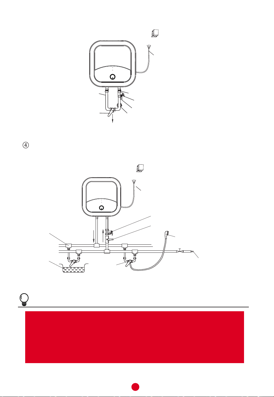
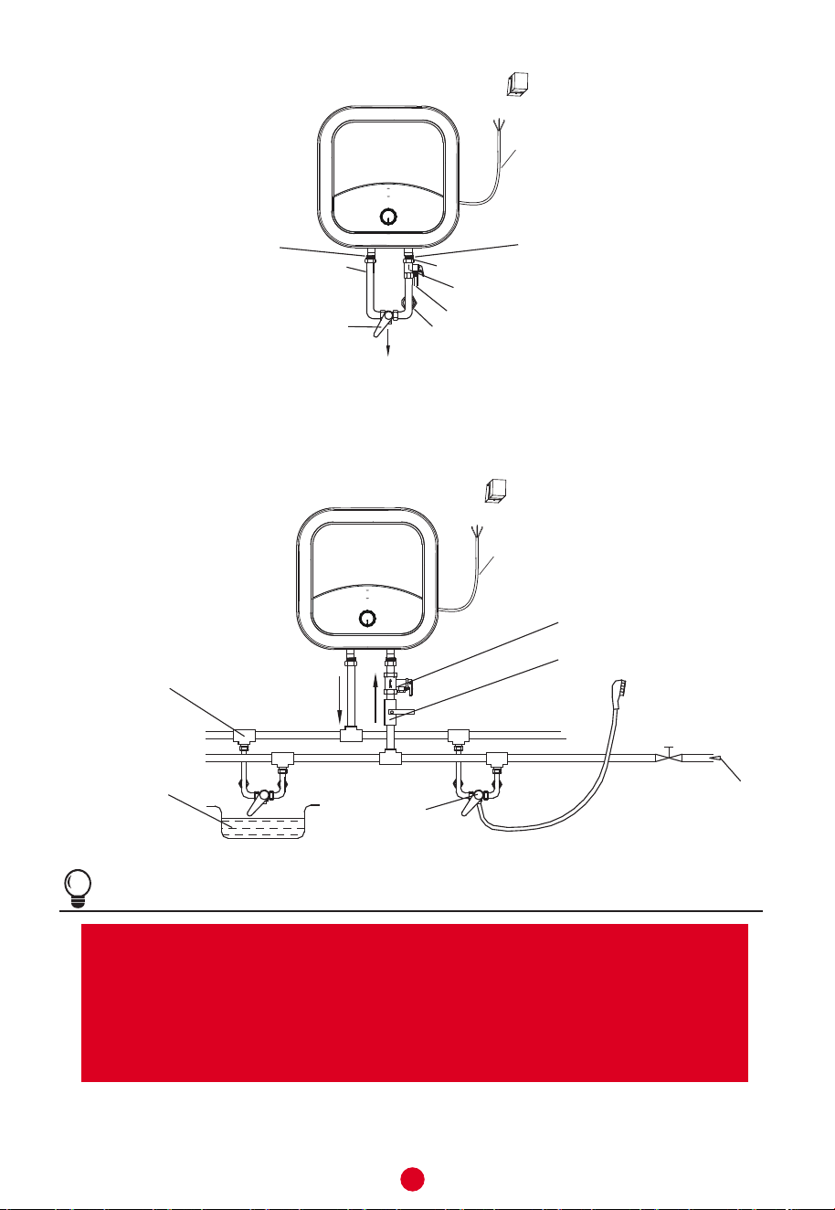
Si el usuario desea realizar un sistema de abastecimiento de vía múltiple, observe el
método ilustrado en la figura 6 para la conexión de mangueras.
Figura 6
Figura 5
Salida de
agua caliente
Entrada de agua fría
Válvula de descarga de presión
Agujero de descarga
Llave de paso de agua
Manivela de ajuste
de mezcla (opcional)
Agua caliente
Cable de alimentación eléctrica
Cable de alimentación eléctrica
Llave de paso de agua
Válvula de entrada de agua
Manguera de entrada
Válvula de
mezcla
Receptáculo
de agua
Unión
triple
Boquilla de la ducha
Válvula de descarga de presión
Salida de
agua
caliente
Entrada
de agua
fría
7
4. MÉTODOS DE UTILIZACIÓN
NOTA
Durante el funcionamiento normal del aparato, la válvula de entrada debe ser mantenida
abierta.
Abrir primeramente cualquiera de las válvulas de salida de agua del termocalefón, luego abrir
la válvula de entrada. El termocalefón se llenará de agua. Cuando el agua fluya por la man-
guera de salida, esto indica que el aparato se ha llenado por completo. En este punto, se pue-
de iniciar el proceso de calentamiento.
Figura 7
Inserte el enchufe de alimentación en la toma eléctrica.
Si el indicador se ilumina, significa que el aparato recibe corriente. El termostato controla
la temperatura del agua dentro del termocalefón de forma automática. Cuando se alcance el
nivel requerido, el aparato pasa al estado de reposo (la luz indicadora se apaga). El ciclo se
inicia nuevamente cuando la temperatura del agua baje (se enfríe).
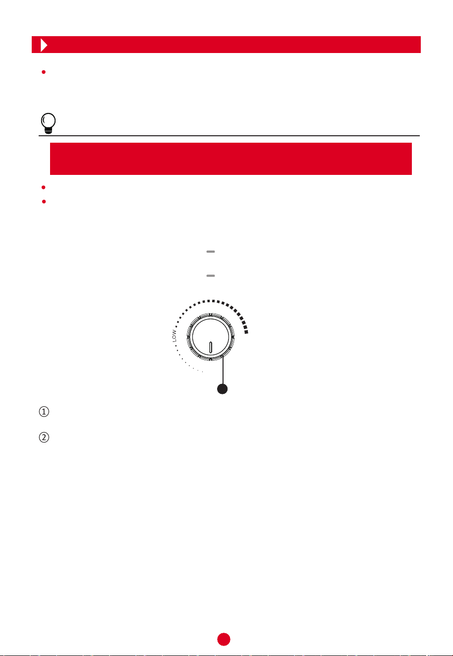
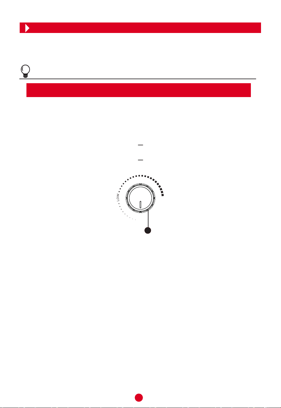
Gire la perilla de izquierda a derecha para aumentar la temperatura y de derecha a izquierda
para disminuirla. La regulación se realiza automáticamente por acción del termostato.
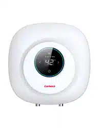
El LED superior corresponde a la luz de encendido. El LED inferior corresponde a la luz de
calentamiento. La luz de encendido se mantiene iluminada cuando hay alimentación eléctrica.
La luz de calentamiento solo se ilumina cuando el termocalefón se encuentra trabajando
(elevando la temperatura del agua) y se apaga cuando finaliza el proceso. Esto depende
de la posición de la perilla.
1
Power
Heating
OFF
MAX
8
Revisar el cable de alimentación y el toma corriente lo más a menudo posible. Asegurarse
de que los contactos eléctricos y las conexiones a tierra se encuentren en buen estado. El
cable y el toma corriente no se deben calentar en exceso.
Si no se va a utilizar el termocalefón durante un período prolongado de tiempo, especial-
mente en regiones con temperatura baja (bajo 0ºC), es necesario drenar el agua del
interior para prevenir daños y averías debido al congelamiento. Consulte la sección de
Precauciones en este manual para para obtener información respecto al procedimiento
de drenaje del agua.
Para asegurar un funcionamiento confiable y prolongado del termocalefón, es necesario
limpiar el tanque interno de manera regular y extraer los sedimentos del termocalefón Tokyo.
Además es recomendable revisar las condiciones de desgaste (completo o no) del ánodo de
magnesio (ubicado en el interior) y si fuese necesario, reemplazarlo con uno nuevo. La fre-
cuencia de la limpieza del tanque depende de la dureza del agua desu zona. Este proceso
deb ser realizado por agentes del Servicio Técnico Autorizado. Consulte con el representante
de la marca para obtener información al respecto.
5. MANTENIMIENTO
ADVERTENCIA
Para evitar riesgos de descargas eléctricas, corte la alimentación de corriente antes de
realizart trabajos de limpieza y/o mantenimiento.
!
!
Figura 8
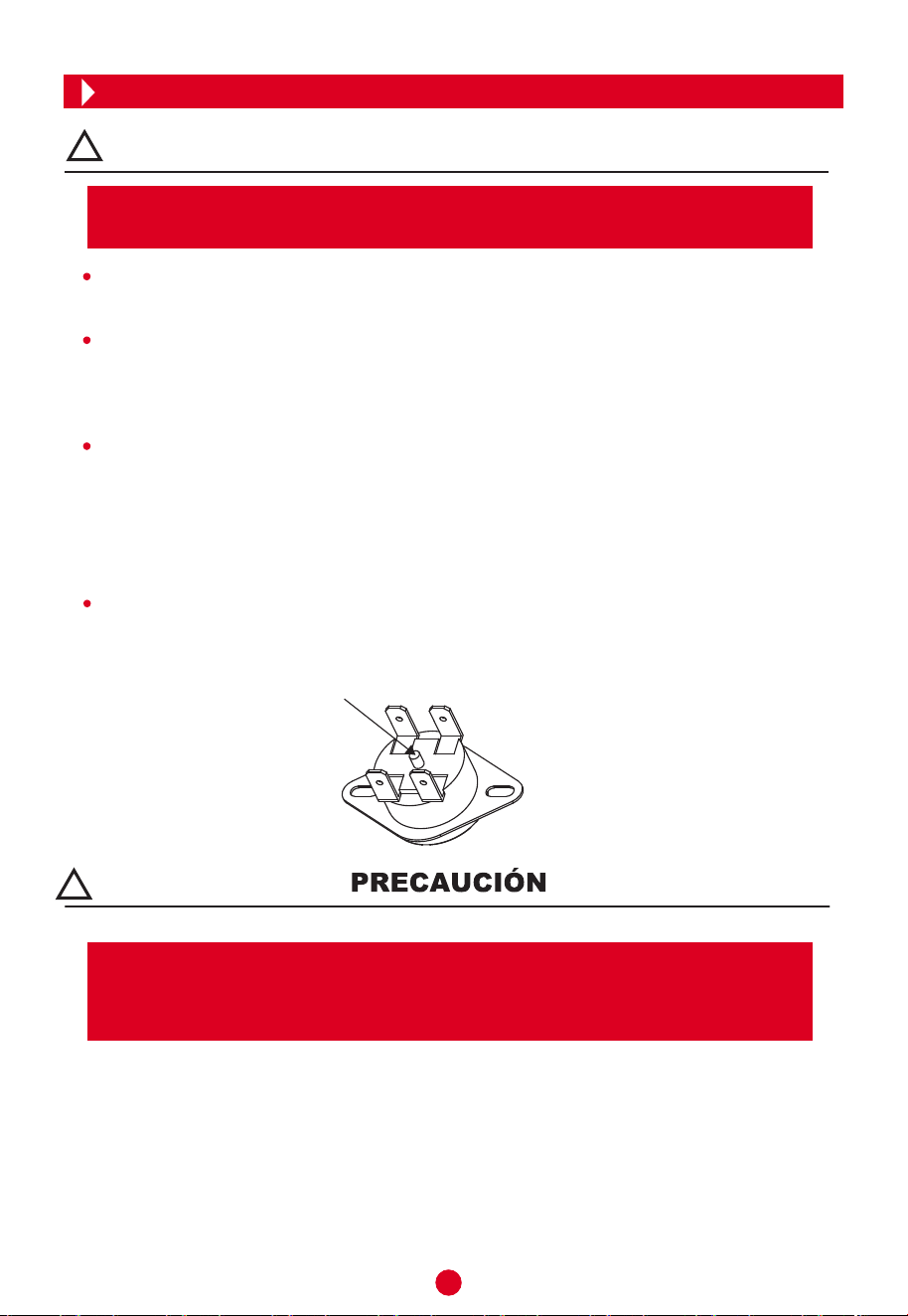
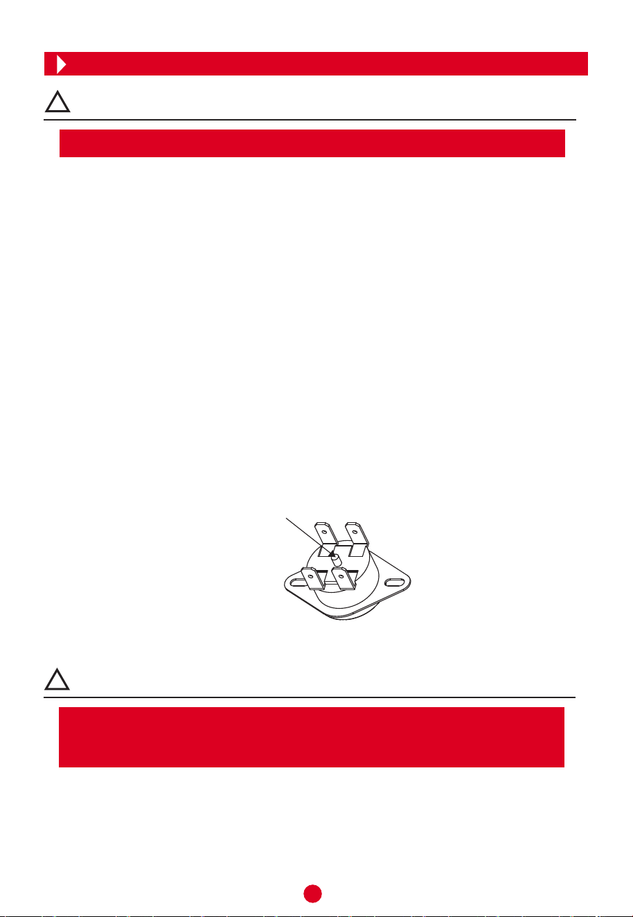
El limitador de temperatura interrumpe el funcionamiento si el termocalefón se sobrecalienta
o si el termostato presenta alguna avería. El limitador debe ser reiniciado manualmente en el
caso que se active por alguna de estas dos razones (Ver Figura 8).
Tenga en cuenta que el desmontaje y reinicio del limitador de temperatura debe ser hecho
por el Servicio Técnico Autorizado o personal similarmente calificado. El representante no
se hace responsable por averías, daños, accidentes y/o lesiones. Para realizar consultas
y averiguaciones sobre su producto Tokyo puede llamar al (021)288 0000.
Botón de reinicio
9
6. RESOLUCIÓN DE PROBLEMAS
NOTA
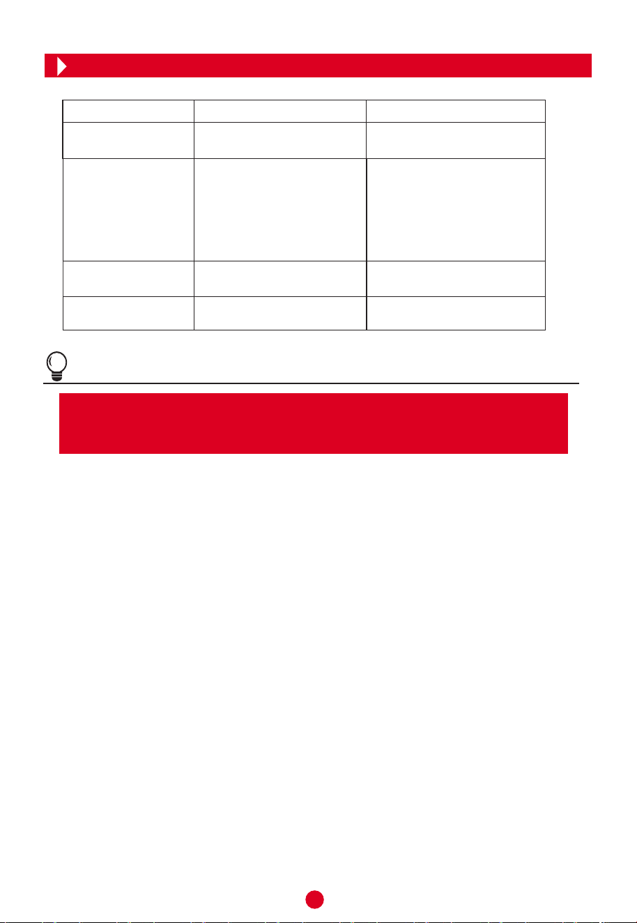
Problema Causa Solución
La luz de calentamiento
está apagada
No sale agua caliente
La temperatura del
agua es muy caliente
Pérdidas de agua
Avería en el regulador
de temperatura (termostato).
1. Se corta la fuente de agua
corriente.
2. La presión del agua es
demasiado baja.
3. La válvula de entrada de
agua no está abierta.
1. Espere a que se restaure el
suministro de agua.
2. Utilice el aparato cuando
aumente la presión.
3. Abra la válvula de entrada de
agua.
Selle las pérdidas instalando
correctamente las juntas y anillos.
Contacte al servicio técnico o
personal especializado.
Avería en el sistema de control
de temperatura (termostato).
Contacte al servicio técnico o
personal especializado.
Las juntas y anillos de goma
están mal colocadas.
Las ilustraciones utilizadas en este material son de carácter referencial y pueden presentar
diferencias con el producto adquirido por usted. Este aparato es solamente para uso do-
méstico. Las especificaciones y características están sujetas a cambios sin previo aviso.
10
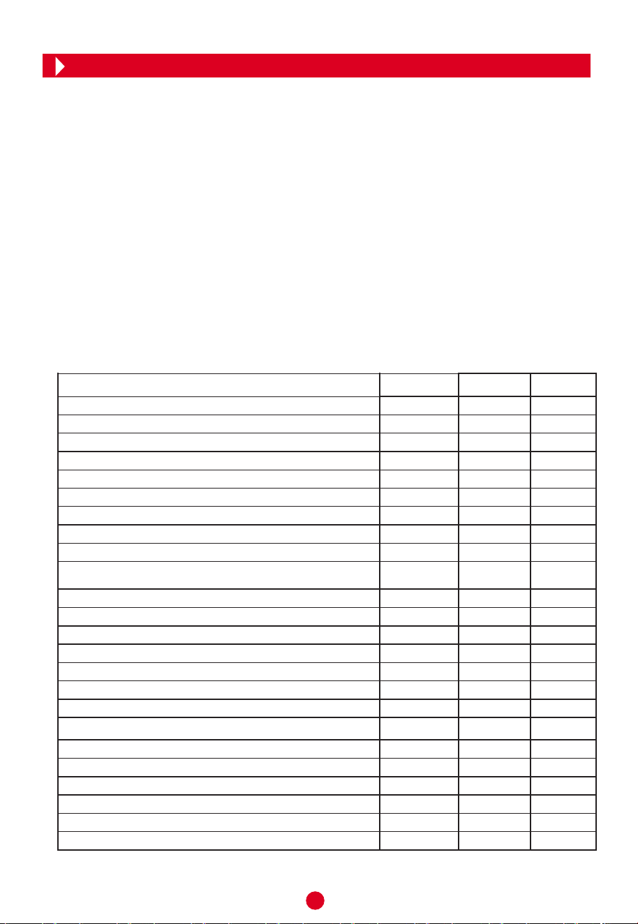
Descripción Parámetros Valor Unit
k-Valor
k
Cumplimiento control inteligente
inteligente
Factor control inteligente
SCF
Conversion coeficiente
CC
Término de corrección ambiental Q
cor
kWh
Energía referente
Q
ref
kWh
Contenido de energía útil
Q
H2O
kWh
Relación de Corrección de referencia y energía útil
Q
ref/
Q
H2O
kWh
Consumo eléctrico diario (medido)
Q
test_elec
kWh
Temperatura del agua al principio del ciclo de medición 24h
T3
℃
Temperatura del agua al final del ciclo de medición 24h
T5
℃
Volumen de almacenamiento
M
act
kg
Volumen de almacenamiento
C
act
L
Consumo de electricidad diaria (corregido)
Q
elec
kWh
El producto cumple y se corresponde con los requisitos de las normas del Reglamento
(No 814/2013) para el calentador de agua de almacenamiento eléctrico y logró una
eficiencia energética del calentamiento de agua ηwh = 33%
De acuerdo con el Anexo II artículo 1 del Reglamento de la comisión de Clases de
Eficiencia energética, La evaluación de los resultados de este informe con respecto
a la conformidad con el Reglamento de la Comisión relacionada (No 812/2013 y
814/2019) es sólo una parte de la evaluación de la conformidad para lograr la
etiqueta ERP
El consumo de electricidad Qelec, ηwh eficiencia energética del calentamiento de
agua energética y agua mezclada a 40 ºC(V40)
Eficiencia energética Calentamiento de agua
η
wh
Consumo de electricidad Anual
AEC
kWh
Clase energética de calentamiento de agua
Temperatura del agua sin gotear
T
set
℃
Temperatura media del agua de salida de agua caliente
θ'
p
℃
Temperatura media del agua de entrad de agua fría
θ
c
℃
Valor normalizado de la temperatura media
θ
p
℃
Volumen de entregade agua de al menos 40 ºC
V
40exp
L
Volumen calculado de entrega de agua caliente de al menos 40 ℃
V
40
L
El calentador de agua de almacenamiento eléctrico CTMVD15CM de la empresa
Corberó Ltd. Fue testado con un perfil de carga declarada del tamaño "XXS"
que corresponden a la clase energética de calentamiento de agua "B"
0.23
0
0
2.5
-0.337
2.1
2.351
0.893
2.955
70
67
15.2
15.2
2.687
32.9
560
B
69.5
63.7
10.4
63.7
10
18
Información de product conforme la regulación UE
11
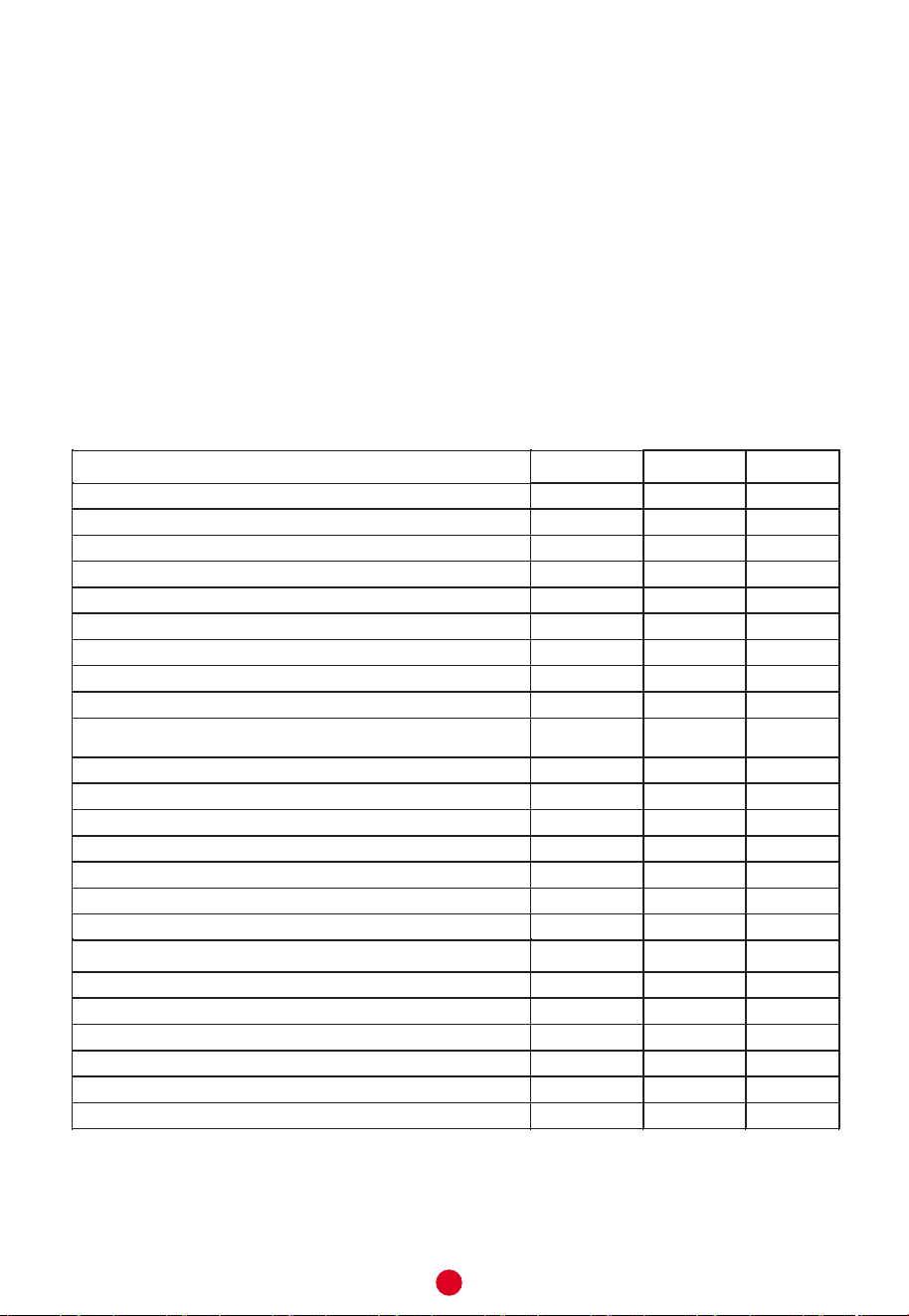
Descripción Parámetros Valor Unit
k-Valor
k
Cumplimiento control inteligente
inteligente
Factor control inteligente
SCF
Conversion coeficiente
CC
Término de corrección ambiental Q
cor
kWh
Energía referente
Q
ref
kWh
Contenido de energía útil
Q
H2O
kWh
Relación de Corrección de referencia y energía útil
Q
ref/
Q
H2O
kWh
Consumo eléctrico diario (medido)
Q
test_elec
kWh
Temperatura del agua al principio del ciclo de medición 24h
T3
℃
Temperatura del agua al final del ciclo de medición 24h
T5
℃
Volumen de almacenamiento
M
act
kg
Volumen de almacenamiento
C
act
L
Consumo de electricidad diaria (corregido)
Q
elec
kWh
El producto cumple y se corresponde con los requisitos de las normas del Reglamento
(No 814/2013) para el calentador de agua de almacenamiento eléctrico y logró una
eficiencia energética del calentamiento de agua ηwh = 33%
De acuerdo con el Anexo II artículo 1 del Reglamento de la comisión de Clases de
Eficiencia energética, La evaluación de los resultados de este informe con respecto
a la conformidad con el Reglamento de la Comisión relacionada (No 812/2013 y
814/2019) es sólo una parte de la evaluación de la conformidad para lograr la
etiqueta ERP
El consumo de electricidad Qelec, ηwh eficiencia energética del calentamiento de
agua energética y agua mezclada a 40 ºC(V40)
Eficiencia energética Calentamiento de agua
η
wh
Consumo de electricidad Anual
AEC
kWh
Clase energética de calentamiento de agua
Temperatura del agua sin gotear
T
set
℃
Temperatura media del agua de salida de agua caliente
θ'
p
℃
Temperatura media del agua de entrad de agua fría
θ
c
℃
Valor normalizado de la temperatura media
θ
p
℃
Volumen de entregade agua de al menos 40 ºC
V
40exp
L
Volumen calculado de entrega de agua caliente de al menos 40 ℃
V
40
L
El calentador de agua de almacenamiento eléctrico CTMVD30CM de la empresa
Corberó Ltd. Fue testado con un perfil de carga declarada del tamaño "S"
que corresponden a la clase energética de calentamiento de agua "C"
0.23
0
0
2.5
-0.321
2.1
2.335
0.899
2.907
76.1
74.7
29.6
29.6
2.658
33.2
555
C
76.8
70.2
10.4
70.1
23
46


Kurbin Lane S.L. Paseo del Ferrocarril 335
08860 Castelldefels BARCELONA (ESPAÑA)
Corbero es una marca registrada bajo licencia
de Electrolux España S.A.
CTMVD30CM
CTMVD15CM
Storage Electric Water Heater
INSTRUCTION MANUAL
1
The installation and maintenance has to be carried out by qualified professionals or authorized
technicians.
The manufacturer shall not be held responsible for any damage or malfunction caused by wrong
installation or failing to comply with following instructions included in this pamphlet.
For more detailed installation and maintenance guidelines, please refer to below chapters.
TITLE PAGE
1.Cautions ...........................................................................................................................(2)
2.Product introduction .........................................................................................................(3)
3.Unit installation .................................................................................................................(5)
4.Methods of using ..............................................................................................................(7)
5.Maintenance.....................................................................................................................(8)
6.Troubleshooting................................................................................................................(9)
7.Produce information with EU regulation .........................................................................(10)
●
●
●
General Remark
TABLE OF CONTENTS
If the supply cord is damaged, it must be replaced by the manufacturer, its service agent or
similarly qualified persons in order to avoid a hazard.
For appliance is not intended for use by persons (including children) with reduced physjsensory
or mental capabilities, or lack of experience and knowledge, unless they have been given
supervision or instruction concerning use of the appliance by a person responsible for their
safety.
Children should be supervised to ensure that they do not play with the appliance
This appliance can be used by children aged from 8 years and above and persons with reduced
physical sensory or mental capabilities or lack of experience and knowledge under the condition
of that they have been given supervision oiinstruction concerning use of the appliance in a safe
way and understand the hazards involved. Children shall not play with the appliance. Cleaning
and user maintenance shall not be made by children without supervision.
●
●
●
●
2
Before installing this water heater,check and confirm that the earthing on the supply socket is
reliably grounded. Otherwise, the electrical water heater can not be installed and used. Do not use
extension boards. Incorrect installation and use of this electrical water heater may result in serious
injuries and loss of property.
Special Cautions
The water heater is not intended for use by persons (including children) with reduced physical,
sensory or mental capabilities, or lack of experience and knowledge, unless they have been given
supervision or instructions concerning use of the appliance by a person responsible for their safety.
Children should be supervised to ensure that they do not play with the heater.
The wall in which the electrical water heater is installed must be able to bear the load more than
two times of the heater filled fully with water without distortion and cracks. Otherwise, other
strengthening measures must be adopted.
The supply socket must be earthed reliably. The installation height of the supply socket must not
be lower than 1.8m. The rated current of the socket must not be lower than 16A. The socket and
plug must be kept dry to prevent electrical leakage. If the flexible power supply cord is damaged, the
special supply cord provided by the manufacturer must be selected, and replaced by the professional
maintenance personnel.
The maximum inlet water pressure is 0.5MPa; the minimum inlet water pressure is 0.1MPa, if this
is necessary for the correct operation of the appliance.
When using the heater for the first time (or the first use after maintenance), the heater can not be
switched on until it has been filled fully with water. When filling the water, at least one of the outlet
valves at the outlet of the heater must be opened to exhaust the air. This valve can be closed after
the heater has been filled fully with water.
The pressure relief valve attached with the heater must be installed at the cold water inlet of this
heater, and make sure it is not exposed in the foggy. The water may be outflowed from pressure
relief valve, so the outflow pipe must open wide in the air. In order to drain away the water inside
the inner container, it can be drained away from the pressure release valve. Twist the thread screw
of the pressure release valve off, and lift the drain handle upwards(See Fig.1) . The drainage pipe
connected to the pressure release hole must be kept sloping downwards and in a frost-free
environment. The water may drip from the discharge pipe of the pressure-relief device and that this
pipe must be left open to the atmosphere.
During heating, there may be drops of water dripping from the pressure release hole of the
pressure relief valve, this is a normal phenomenon. The pressure release hole shall not be blocked
under no circumstances, otherwise, the heater may get damaged, even resulting in accidents. If
there is a large amount of water leak, please contact customer care center for repair.
The pressure relief valve need to be checked and cleaned regularly, so as to make sure it will not
be blocked.
Since the water temperature inside the heater can reach up to 75℃, the hot water must not be
exposed to human bodies when it is initially used. Adjust the water temperature to a suitable
temperature to avoid scalding.
If any parts and components of this electrical water heater are damaged please contact customer
care center for repair.
1. CAUTIONS
3
2.1 Technical Performance Parameters
2.2 Brief introduction of product structure
(Fig.1)
Hot water
Cold water
Pressure relief valve
Thread screw
Drain handle
Pressure release hole
CTMVD15CM
CTMVD30CM
Rated
Voltage
(ACV)
220-240
220-240
Model
IPX4
IPX4
75
75
75
75
1500
1500
Rated
Power
(W)
15
30
Volume
(L)
0.75
0.75
Rated
Pressure
(MPa)
Rated Of Water
Temperature
(°C)
Rated
Thermostat
SET(°C)
Protection
Class
Waterproof
Grade
I
I
(Note:All dimensions are in mm)
C
A
B
D
A
B
C
D
368
368
297
66
440
440
385
66
CTMVD15CM CTMVD30CM
2. PRODUCT INTRODUCTION
4
2.3 Internal Wire Diagram
WIRING DIAGRAM
E
N
L
Q
Q
Heating Element
Heating Indicator light
Thermal
Cut Out
Thermostat
Power
Indicator
Brown
Blue
Yellow/Green
5
N (Blue)
Ground
≥1.8m
L (Brown)
E (Yellow/Green)
3.2 Pipelines Connection
3.1 Installation Instruction
①
②
③
This electrical water heater shall be installed on a solid wall. If the strength of the wall cannot bear
the load equal to two times of the total weight of the heater filled fully with water, it is then neces-
sary to install a special support.
In case of hollow bricks wall, ensure to fill it with cement concrete completely.
After selecting a proper location, install the mounting bracket to a solid wall.
Methods of installation: Follow the installation as shown in Fig.3. Use the anchors and fasteners
provided along with the product for securing the bracket(Fig.2) firmly in the wall.
Align the slots on the back of the water heater with the projections on the bracket and mount the
water heater on the bracket. Thereafter slide the water heater gently towards the bottom side on
lock the water heater.
①
②
③
The dimension of each pipe part is G1/2” ; The massive pressure of inlet should use Pa as the
unit; The minimum pressure of inlet should use Pa as the unit.
Connection of pressure relief valve with the heater on the inlet of the water heater.
In order to avoid leakage when connecting the pipelines, the rubber seal gaskets provided with the
heater must be added at the end of the threads to ensure leak proof joints (see Fig.5).
(Fig.2) (Fig.3)
If the bathroom is too small, the heater can be installed at another place. However, in order to
reduce the pipeline heat losses, the installation position of the heater shall be closed to the
location shall be as near as possible to the heater.
④
Install the supply socket in the wall. The requirements for the socket are as follows: 250V/10A, single
phase, three electrodes. It is recommended to placed the socket on the right above the heater.
The height of the socket to the ground shall not be less than 1.8m (see Fig.4).
(Fig.4)
⑤
100
36
20
66
2-Φ8.5
2.2
3. UNIT INSTALLATION
NOTE
Please be sure to use the accessories provided by our company to install this electric
water heater. This electric water heater can not be hung on the support until it has been
confirmed to be firm and reliable. Otherwise, the electric water heater may drop off from
the wall, resulting in damage of the heater, even serious accidents of injury. When
determining the locations of the bolt holes, it shall be ensured that there is a clearance
not less than 0.2m on the right side of the electric heater, to convenient the maintenance
of the heater, if necessary.
If the users want to realize a multi-way supply system, refer to the method shown in fig.5 for
connection of the pipelines.
④
6
(Fig.4)
(Fig.5)
Pressure relief valve
Water inlet valve
Water inlet valve
Running water pipe
Mixing valve
Water pool
Triple joint
Shower nozzle
Hot water outlet
Cold water inlet
Pressure relief valve
Pressure release hole
Joint screw for cold water inlet
Adjusting handle for
mixing valve
Hot water
Hot water
outlet
Cold water
inlet
Rubber seal gaskets
Rubber seal gaskets
Power cord
Power cord
7
(Fig.6)
NOTE
During normal operation, the inlet valve shall be always kept open.
First, open any one of the outlet valves at the outlet of the water heater, then, open the inlet valve.
The water heater gets filled with water. When water flows out of the outlet pipe it implies that the
heater has been filled fully with water, and the outlet valve can be closed.
Insert the supply plug into the socket.
●
●
If the indicator lights up, the thermostat will automatically control the temperature. When the water
temperature inside the heater has reached the set temperature, it will switch off automatically,
when the water temperature falls below the set point the heater will be turned on automatically to
restore the heating.
●
①
②
Rotate the knob according to the marking on the knob to increase or decrease the setting
temperature.
The White (up) LED is the power light. The White (down) LED is the heating light. The power light
remains ON when machine is connected to power. The heating light will be ON once the knob is
rotated to adjust the temperature and will be OFF when the heating process is finished.
1
Power
Heating
OFF
MAX
4. METHODS OF USING
8
Manual reset button
Check the power plug and outlet as often as possible. Secure electrical contact and also proper
grounding must be provided. The plug and outlet must not heat excessively.
If the heater is not used for a long time, especially in regions with low air temperature(below 0℃),
it is necessary to drain water from the heater to prevent damage of the water heater, due to water
freezing in the internal tank.(Refer Cautions in this manual for the method to drain away the water
from the inner container).
To ensure long reliable water heater operation, it is recommended to regularly clean the internal
tank and remove deposits on the electric heating element of the water heater, as well as check
condition (fully decomposed or not) of the magnesium anode and, if necessary, replace it with a
new one in case of full decomposition.Tank cleaning frequency depends on hardness of water
located in this territory. Cleaning must be performed by special maintenance services. You can ask
the seller for address of the nearest service center.
●
●
●
●
WARNING
Do cut off power supply before maintenance, to avoid danger like electric shock.
!
WARNING
Non-professionals are not allowed to disassemble the thermal switch to reset.
Please contact professionals to maintain. Otherwise our company will not take
responsibility if any quality accident happens because of this.
!
The water heater is equipped with a thermal switch, which cuts off power supply of the heating element upon
water overheating or its absence in the water heater. If the water heater is connected to the mains, but water
is not heated and the indicator doesn’t light up, then the thermal switch was switched off or not switched on.
To reset the water heater to the operating condition, it is necessary to:
1. De-energize the water heater, remove the plate of the side/lower cover.
2. Press the button, located at the center of the thermal switch, see Fig.7;
3. If the button is not pressed and there is no clicking, then you should wait until the thermal switch
cools down to the initial temperature.
(Fig.7)
5. MAINTENANCE
9
NOTE
Parts illustrated in this use and care manual are indicative only, parts provided with the
product may differ with illustrations.This product is intended for household use only.
Specifications are subject to change without notice.
Failures Reasons Treatment
The heating indicator
light is off.
Failures of the temperature
controller.
Contact with the professional
personnel for repair.
Contact with the professional
personnel for repair.
No water coming out
of the hot water outlet.
The water temperature
is too high.
Water leak.
1. The running water supply
is cut off.
2. The hydraulic pressure is
too low.
3. The inlet valve of running
water is not open.
1. Wait for restoration of
running water supply.
2. Use the heater again
when the hydraulic
pressure is increased.
3. Open the inlet valve of
running water.
Failures of the temperature
control system.
Seal problem of the joint of
each pipe.
Seal up the joints.
6. TROUBLESHOOTING
10
0.23
0
0
2.5
-0.337
2.1
2.351
0.893
2.955
70
67
15.2
15.2
2.687
32.9
560
B
69.5
63.7
10.4
63.7
10
18
Description tinUeulaVretemaraP
k-Value k
Smart control compliance smart
Smart control factor SCF
Conversion coefficient CC
Ambient correction term Q
cor
kWh
Referenct energy
Q
ref
kWh
Useful energy content Q
H2O
kWh
Correction ratio of reference and useful energy Q
ref/
Q
H2O
kWh
Daily electricity consumption (measured) Q
test_elec
kWh
Water temperature at the beginning of the 24h measurement
cycle
T3
℃
Water temperature at the end of the 24h measurement cycle
T5
℃
Storage volume M
act
kg
Storage volume C
act
L
Daily electricity consumption (corrected) Q
elec
kWh
that correspond to the water heating efficiency class
The product fulfills and corresponds to the requirements of the commission regulation
standards (No 814/2013) for electrical storage water heater and achieved a water
heating energy efficiency of
The evaluation of the result of this report with respect of conformity with the related
commission regulation (No 812/2013 and 814/2019) is only a part of the conformity
assessment to achieve the ErP-Label.
Electricity
consumption Qelec、water heating energy efficiency ηwh and mixed water
at 40℃(V40)
“B”
η
wh
=33%
Water heating energy efficiency
η
wh
Annual Electricity Consumption
AEC kWh
Water heating energy efficiency class
Description Parameter Value Unit
Water temperature without tapping
T
set
℃
Average water temperature of outlet warm water
θ'
p
℃
Average water temperature of inlet cold water
θ
c
℃
Normalised value of the average temperature
θ
p
℃
Volume that delivered water of at least 40℃
V
40exp
L
Calculated volume that delivered hot water of at least 40℃
V
40
L
The electrical storage water heater CTMVD15CM of the company Midea was tested
with a declared load profile of the size “XXS”
In accordance with Annex
II Enercy Efficiency Classes article 1 of the commission
regulation (No 812/2013)
7. Produce information with EU regulation
11
The electrical storage water heater CTMVD30CM of the company Midea was tested
with a declared load profile of the size “S”
Description tinUeulaVretemaraP
k-Value k
Smart control compliance smart
Smart control factor SCF
Conversion coefficient CC
Ambient correction term Q
cor
kWh
Referenct energy
Q
ref
kWh
Useful energy content Q
H2O
kWh
Correction ratio of reference and useful energy Q
ref/
Q
H2O
kWh
Daily electricity consumption (measured) Q
test_elec
kWh
Water temperature at the beginning of the 24h measurement
cycle
T3
℃
Water temperature at the end of the 24h measurement cycle
T5
℃
Storage volume M
act
kg
Storage volume C
act
L
Daily electricity consumption (corrected) Q
elec
kWh
that correspond to the water heating efficiency class
The product fulfills and corresponds to the requirements of the commission regulation
standards (No 814/2013) for electrical storage water heater and achieved a water
heating energy efficiency of
In accordance with Annex II Enercy Efficiency Classes article 1 of the commission
regulation (No 812/2013)
The evaluation of the result of this report with respect of conformity with the related
commission regulation (No 812/2013 and 814/2019)
is only a part of the conformity
assessment to achieve the ErP-Label.
Electricity consumption Q
elec、water heating energy efficiency ηwh and mixed water
at 40℃(V40)
“C”
η
wh=33%
Water heating energy efficiency
η
wh
Annual Electricity Consumption
AEC kWh
%
Water heating energy efficiency class
Description Parameter Value Unit
Water temperature without tapping
T
set
℃
Average water temperature of outlet warm water
θ'
p
℃
Average water temperature of inlet cold water
θ
c
℃
Normalised value of the average temperature
θ
p
℃
Volume that delivered water of at least 40℃
V
40exp
L
Calculated volume that delivered hot water of at least 40℃
V
40
L
0.23
0
0
2.5
-0.321
2.1
2.335
0.899
2.907
76.1
74.7
29.6
29.6
2.658
33.2
555
C
76.8
70.2
10.4
70.1
23
46


Kurbin Lane S.L. Paseo del Ferrocarril 335
08860 Castelldefels BARCELONA (ESPAÑA)
Corbero es una marca registrada bajo licencia
de Electrolux España S.A.

CERTIFICADO DE GARANTÍA
Imprescindible la presentación de la factura de compra acompañada del presente certificado de garantía.
Riesgos cubiertos.
Este aparato está garantizado contra cualquier defecto de funcionamiento, siempre que se destine a uso doméstico,
procediéndose a su reparación dentro del plazo de garantía y sólo por la red de SAT autorizados.
Nuestros electrodomésticos Corberó cuentan con la garantía legal del fabricante que cubre cualquier avería o defecto durante
36 meses, desde su fecha factura de 1 de enero del 2022. En caso de que fuera necesario, nosotros nos ocupamos de cualquier
posibleincidencia siempre que se deba a un componente defectuoso o fallo de fabricación.
Excepciones de garantía.
•
Que la fecha del certificado no coincida con la fecha de venta de la factura original.
•
Averías producidas por golpe, por caída o cualquier otra causa de fuerza mayor.
•
Si el aparato ha sido manipulado por personal
no autorizado.
•
Las averías producidas o derivadas como consecuencia de un uso inadecuado, por defectos de
instalación,por introducir modificaciones en el aparato que alteren su funcionamiento.
•
Puestas en marcha, mantenimiento, limpiezas, componentes sujetos a desgaste, lámparas, piezas estéticas,
oxidaciones, plásticos, gomas, carcasas y cristales.
•
Los hornos microondas (a excepción de los integrables) y los hornos sobremesa en el caso de cualquier
incidencia de
funcionamiento, deben de llevarse al servicio técnico más próximo por parte del cliente. No se
recogen ni reparan en eldomicilio.
•
Garantía termos eléctricos. Garantía de 3 años incluyendo los costes de desplazamiento y mano de obra que
correspondan de la reparación del producto, debiendo tener un mantenimiento una vez cada 12 meses.
Especialmente si Ud. ha instalado un aparato a gas, tenga presente como titular de la instalación, la obligatoriedad de
realizar una revisión completa de los equipos, (según Real Decreto 238 / 2013, del 5 abril. RITE. IT3, M. Lo termos
eléctricos y calderas que incluyen depósitos acumuladores de agua caliente, para que se aplique la prestación de la
Garantía, es obligatorio que el ánodo de magnesio esté operativo y que realice la función de protección
adecuadamente. Para ello es recomendable que el ánodo se revise bianualmente por el Servicio Oficial y sea
renovado cuando fuera necesario. Periodicidad que deberá ser anual en aquellas zonas con aguas críticas (contenido
de CaCO3 superiores a 200mg/L, es decir a partir de 20ºfH de dureza). Depósitos sin el correcto estado del ánodo de
protección, notienen la cobertura de la garantía. Independientemente del tipo de depósito o producto, todas las
válvulas de sobrepresión de calefacción o a.c.s., deberán ser canalizadas para evitar daños en Ia vivienda por
descargas de agua. La garantía del producto no asume los daños causados por Ia no canalización del agua
derramada por esta válvula.
•
Garantía de estufas de Pellets y Estufas de gas, necesario disponer de la acreditación de puesta en marcha del SAT
oficial Corberó, para beneficiarse del servicio de garantía de 3 años.
“ESTAS EXCEPCIONES ANULAN LA GARANTÍA, SIENDO LA REPARACIÓN CON CARGO AL CLIENTE”
Periodo amparado en aparatos según ley de garantias en la venta de bienes de consumo Ley vigente es “RD 7/2021”
Sevicio Técnico Oficial:
911 08 08 08
Horario de atención Lunes a Viernes de 9h00 a 19h00. Teléfono de contacto_ 911 08 08 08 Mail de contacto_ info@corbero.es web_
www.corbero.es
Dirección de Servicio técnico oficial_Vidal i Ribes 8-10 08950 Esplugues de Llobregat Barcelona
CERTIFICATE OF GUARANTEE
The presentation of the purchase invoice accompanied by this guarantee certificate is essential.
Covered Risks.
This appliance is guaranteed against any malfunction, provided that it is intended for domestic use, proceeding to its repair
withinthe warranty period and only by the authorized SAT network.
Our Corberó appliances have the manufacturer's legal warranty that covers any breakdown or defect for 36 months, from the
invoice date of January 1, 2022. If necessary, we take care of any possible incident whenever it is due to a defective component
ormanufacturing fault. Warranty Exceptions
Warranty Exceptions
•
That the date of the certificate does not coincide with the date of sale of the original invoice.
•
Faults produced by blow, by fall or any other cause of force majeure.
•
If the device has been manipulated by unauthorized personnel.
•
Faults produced or derived as a consequence of improper use, installation defects, or modifications to the device
that
alter its operation.
•
Start-up, maintenance, cleaning, components subject to wear, lamps, aesthetic
parts,
oxidation, plastics, rubbers, housings and crystals.
•
Microwave ovens (with the exception of built-in ones) and tabletop ovens in the event of any incident of
operation, they must be taken to the nearest technical service by the customer. They are not collected or repaired at
home.
•
Electric thermos guarantee. 3-year warranty including travel and labor costs that correspond to the repair of the
product, having to have maintenance once every 12 months. Especially if you have installed a gas appliance, keep in
mind as the owner of the installation, the obligation to carry out a complete review of the equipment, (according to
Royal Decree 238 / 2013, of April 5. RITE. IT3, M. Lo thermos electrical and boilers that include hot water storage tanks,
for the benefit of the Guarantee to apply, it is mandatory that the magnesium anode is operational and that it
performsthe protection function adequately.For this, it is recommended that the anode be checked biannually by the
Official Service and is renewed when necessary Periodicity that must be annual in those areas with critical waters
(CaCO3 content greater than 200mg/L, that is, from 20ºfH of hardness) Deposits without the correct state of the
protection anode are not covered by the warranty Regardless of the type of tank or product, all heating or DHW
overpressure valves must be channeled to avoid damage and n the house due to water discharges. The product
warranty does not cover damages caused by not channeling the water spilled by this valve.
•
Guarantee of pellet stoves , Gas Stoves, it is necessary to have the start-up accreditation from Corberó SAT, to benefit
from the 3-year guarantee service.
“THESE EXCEPTIONS VOID THE WARRANTY, THE REPAIR BEING CHARGED TO THE CUSTOMER”
Period covered in devices according to the law of guarantees in the sale of consumer goods Current law is “RD 7/2021”
Official Technical Service:
911 08 08 08
Hours of operation Monday to Friday from9h00 a 19h00. Telephone contact_ 911 08 08 08 Contact email_ info@corbero.es web_ www.corbero.es
Official Technical Service Address_Vidal i Ribes 8-10 08950 Esplugues de Llobregat Barcelona
CERTIFICADO DE GARANTIA
A apresentação da factura de compra acompanhada deste certificado de garantia é indispensável.
Riscos cobertos.
Este aparelho está garantido contra qualquer avaria, desde que se destine ao uso doméstico, reparando-o dentro do período
degarantia e apenas pela rede SAT autorizada.
Nossos eletrodomésticos Corberó têm garantia legal do fabricante que cobre qualquer avaria ou defeito por 36 meses, a partir
dadata da fatura de 1º de janeiro de 2022. Se necessário, cuidamos de qualquer eventual incidente desde que seja devido a um
componente ou fabricação defeituoso falta.
Exceções de garantia.
•
Que a data do certificado não coincida com a data de venda da fatura original.
•
Avarias causadas por pancadas, quedas ou qualquer outra causa de força maior.
•
Se o dispositivo foi adulterado por pessoal não autorizado.
•
Avarias produzidas ou derivadas como resultado de uso indevido, defeitos de instalação, fazendo alterações
no
dispositivo que alteram seu funcionamento.
•
Comissionamento, manutenção, limpeza, componentes sujeitos a desgaste, lâmpadas, peças
estéticas,
oxidação, plásticos, borrachas, invólucros e vidros.
•
Fornos de microondas (exceto os embutidos) e fornos de mesa em caso de qualquer incidência de
operação, devem ser levados ao serviço técnico mais próximo pelo cliente. Eles não são recolhidos ou reparados em
casa.
•
Garantia térmica elétrica. Garantia de 3 anos incluindo despesas de deslocação e mão-de-obra que correspondam à
reparação do produto, devendo ter manutenção a cada 12 meses. Especialmente se instalou um aparelho a gás,
tenha em atenção como proprietário da instalação, a obrigação de realizar uma revisão completa do equipamento,
(de acordocom o Decreto-Lei n.º 84/2021. Lo thermos eléctricos e caldeiras que incluam acumuladores de água
quente, para o benefício da Garantia a aplicar, é obrigatório que o ânodo de magnésio esteja operacional e que
desempenhe a função de protecção de forma adequada. ser verificado a cada dois anos no Serviço Oficial e renovado
quando necessário Periodicidade que deve ser anual nas áreas com águas críticas (teor de CaCO3 superior a 200mg/L,
ou seja, a partir de 20ºfH de dureza) Depósitos sem o estado correto do ânodo de proteção não estão cobertos pela
garantia Independentemente do tipo de tanque ou produto, todas as válvulas de aquecimento ou de
sobrepressão deágua quente sanitária devem ser canalizadas
para
evitar
danos
e na casa devido a
descargas de
água. A garantia do produto não cobre danos causadospela não canalização da água derramada por esta válvula.
Garantia das estufas a Pellets, Fogões a gás, é necessário ter a acreditação de arranque do oficial Corberó SAT, para
beneficiar do serviço de garantia de 3 anos.
“ESTAS EXCEÇÕES ANULAM A GARANTIA, SENDO A REPARAÇÃO POR CONTA DO CLIENTE.”
Período
abrangido em dispositivos de acordo com a lei de garantias na venda de bens de consumo A lei atual é "Decreto-Lei n.º 84/2021"
Serviço Técnico Oficial:
351 225 191 300
Horário de atendimento de segunda a sexta das 9h às 19h. Telefone de contato_ 351 225 191 300 Email de contato_
info@corbero.esweb_ www.corbero.es Serviço Técnico Oficial Endereço_Vidal i Ribes 8-10 08950 Esplugues de Llobregat Barcelona