
2
I
Model Number AE-238, AE-243 AE-23A, AE-23B, AE-
23C, AE-23D
AE-239, AE-244 AE-23E-v2, AE-23F
Power Input 24V AC/ DC 24V AC/ 28V DC PoE: 50~57V DC PoE 802.3 bt, (AE-23E-v2)
PoE 50~57V DC, (AE-23F)
Max. Output power
budget
30W 80W, 100W (-AIW) 30W 15.4-30W PoE
30-60W PoE
60W - 95W PoE
Power Consumption Window heater: 10W;
Blower: 2W; Camera: 6 ~
8W
Window heater: 10W;
Blower: 2W; Camera: 6
~ 8W; Cold start heater:
30W
Window heater: 5W;
Blower: 2W; Camera: 6 ~
8W; IR: 6W
Window heater: 10W;
Blower: 2W; Camera: 6 ~
8W; Wiper: 6W
Environmental
Operation Temp.
-20°C ~ +65°C -20°C ~ +65°C
-20°C ~ +50°C (w/ IR)
-40°C (Cold start)
-20°C ~ +65°C
-20°C ~ +50°C (w/ IR)
-20°C ~ +65°C
-20°C ~ +50°C (w/ IR)
Window heater ON/OFF ≤ 30°C ON; ≥ 35°C OFF ≤ 30°C ON; ≥ 35°C OFF ≤ 30°C ON; ≥ 35°C OFF ≤ 30°C ON; ≥ 35°C OFF
Blower Control ≥40°C ON; ≤ 35°C OFF ≥40°C ON; ≤ 35°C OFF ≥40°C ON; ≤ 35°C OFF ≥40°C ON; ≤ 35°C OFF
Protection Level IP67, IK10 IP67, IK10 (IP66 w/ wiper) IP67, IK10 IP67, IK10 (IP66 w/ wiper)
Construction Die-cast Aluminum Alloy Die-cast Aluminum Alloy Die-cast Aluminum Alloy Die-cast Aluminum Alloy
Coating White epoxy powder
coating
White epoxy powder
coating
White epoxy powder
coating
White epoxy powder
coating
Dimensions 415 (L) x 170 (W) x 125 (H)
mm
502.8 (L) x 170 (W) x
135.5 (H) mm
415 (L) x 170 (W) x 125 (H)
mm - IR not included
502.8 (L) x 170 (W) x 135.5
(H) mm - IR not included
Net Weight 2,2kg (4.84 lb) 2,7kg (5.95 lb), 2,8kg (6.18
lb - wiper model)
2,2kg (4.85 lb) 2,7kg (5.95 lb), 2,8kg (6.18
lb - wiper model)
UNPACKING:
Unpack carefully. Electronic components can be damaged if improperly handled or
dropped. If an item appears damaged in shipment, place it properly in its carton and
notify the shipper.
IMPORTANT!:
1. Read and follow Instructions: All operating and user instructions should be read and
followed before the unit is to be operated.
connections.
If you plan to install this camera enclosure into a tropical, sea coastal, or an environment
where salt water or corrosive industrial waste water/moist are present, please seal each
This will help prevent
electrolysis to occur and extend the life span of the camera and housing.
3
Revision History:
Rev. 1.0: Initial release.
Rev. 1.1: Added the Accessory list and updated environmental parameters: Added the distribution board
drawing for the AE-23E and -23F.
Package Contents:
1. T30 L wrench.
2. 2x M4x8
3. Truss head screw: 1x 1/4"-20X1/4"
4. Truss head screw: 1x 1/4"-20X3/8"
5. 1x Plastic buffer plate:
IMPORTANT:
1. Disconnect devices: A readily accessible disconnect device in the building installation wiring
should be incorporated.
2.
Rev. 1.3 revise specification and part number of AE-23E/23F

4
II
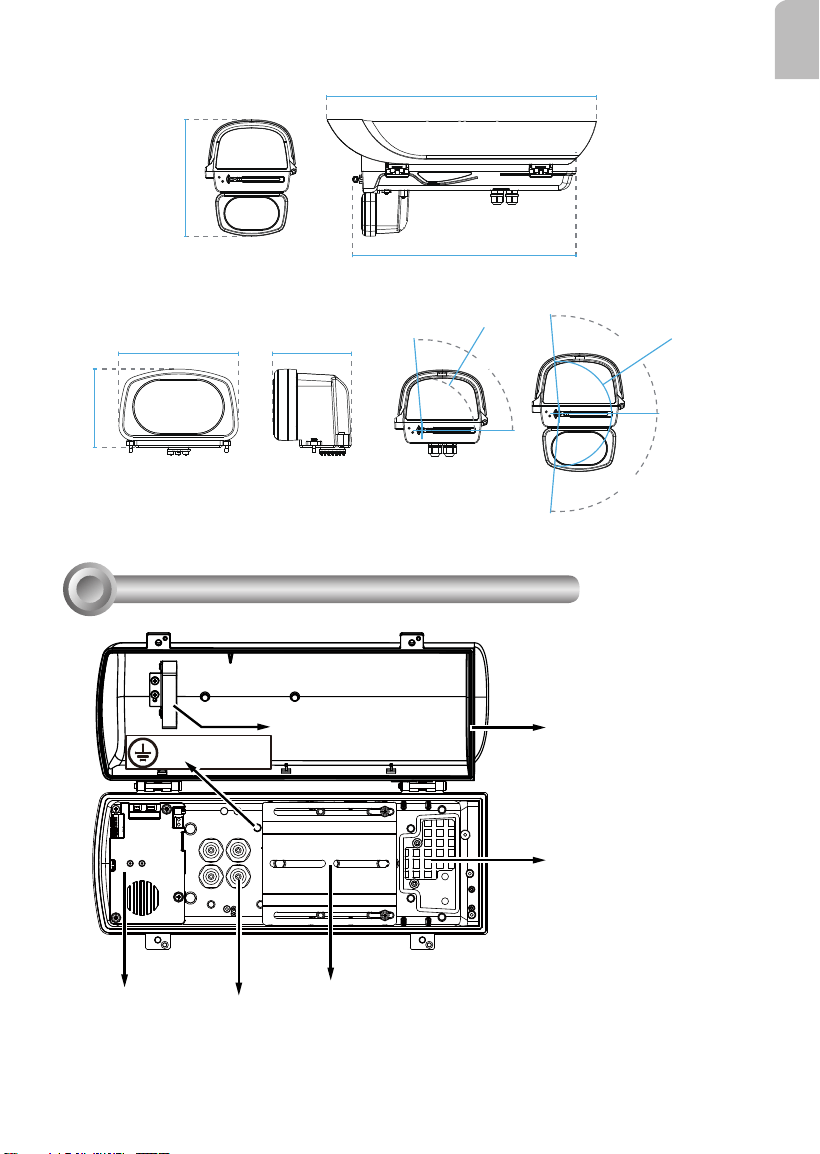
Swivel Positions and Directions
415 mm
125 mm
170 mm
400 mm
255 mm
USABLE AREA
105 mm
77.4 mm
USABLE
AREA
105 mm
502.8 mm
135.5 mm
158.5 mm
170 mm
400 mm
77.4 mm
USABLE
AREA
255 mm
USABLE AREA
AE-238, AE-239
AE-23A, 23B, 23C, 23D, 23E-v2, 23F
415 mm
206.9 mm
170 mm
400 mm
135 mm
88.05 mm
87.01 mm
AE-243, AE-244
5
English
Component Description
III
Camera Mounting Platform
M16 1/2" Waterproof cable glands
AC/DC or PoE Power
distribution board
Ventilation fan
Window frame
heater coil
217.4 mm
502.8 mm
417 mm
135 mm
88.05 mm
87.01 mm
95˚
R96.5
95˚
95˚
R96.45
Dimensions with the IR unit and wiper
VAIR module
Ground M4 x5
6
Installation
V
Installation Suggestions
IV
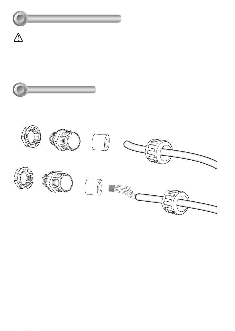
1.
Prepare power wires, a ground wire, and a CAT5e Ethernet cable. Pass them through
the M16 waterproof connectors and its waterproof components.
• When installing a housing that comes with an IR illuminator:
Please avoid eye exposure or apply appropriate protection, such as wearing a pair of Infrared
protection glasses, when working with the product. Always use camera live view to oberve IR
lighting effects.
WARNING:
Ethernet cable Ø4 ~ 6.5mm
Power wires & DI/DO wires,
a combo cable from IR illuminator
(if applied)
Note that some cables are connected when shipped. You do not need to connect heater,
blower, and the front IR powere wires.

7
English
o
O
g
B
b
G
br
BR
1
2
3
4
5
6
7
8
o: white/orange stripe
O: orange solid
g: white/green stripe
B: blue solid
b: white/blue stripe
G: green solid
br: white/brown stripe
BR: brown solid
You may need to remove the RJ45 connector, and use a crimping tool to connect the
Ethernet wires to an RJ45 connector inside the enclosure. Use an Ethernet cable of the
width of 5 ~ 6.5mm.
2.
When done, tighten up and install the waterproof connectors.
3.
Assemble the camera components, e.g., the CS ring and lens module. Secure the
mounting plate to the bottom of the camera (the label side) using the included screw.

8
Lens flush
w/ edge of
enclosure
4.
Adjust the camera's position so that the lens module can ush align with the tempered
glass. Secure the camera using the screws and washers to the bottom of the housing.
Intrusion Alarm - Available on AE-23A/B/C/D/E/F.
If preferred, install the intrusion alarm switch to the side of enclosure, and connect the detection wires
to camera DI.
9
English
5.
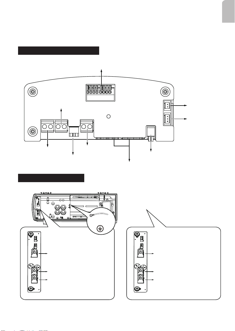
Connect 24V power source to the power input terminal. Connect power wires from the
DC 12V output to the camera. You may also connect the 24V power to drive an external
IRs.
Below is the distribution board drawing power from 24V AC/DC.
Heater
Blower
IR angle selector
I/O terminal block
Camera heater
24V AC/DC IN
12V DC OUT
24V AC/DC OUT
Connectors to the front IR
Power LED
AE-23A, AE-23B, AE-23C, AE-23D
AE-238, AE-243
DC 12V OUT - to camera
AC 24V OUT - to external IR
AC 24V IN
Ground
for IR LED
AC 24V OUT - to camera
AC 24V IN
AE-238
AE-243

10
Below is the distribution board (AE-239, -244) that draws power from a 30/60/95W PoE
PSE. Note that the AE-239 and AE-244 provide 12V DC output.
Heater
Blower
IR angle selector
PoE power LED
12V DC OUT
PoE IN
Connectors to
the front IR
Wiper / Camera heater
PoE OUT
I/O terminal block (No use)
Below is the distribution board (AE-23E-v2/23F) that draws power from a 30/60/95W PoE
PSE.
Heater
Blower
IR angle selector
PoE power LED
24V DC OUT
PoE IN
Connectors to
the front IR
Wiper / Camera heater
PoE OUT
I/O terminal block
AE-23E-v2, AE-23F
AE-239, AE-244

11
English
Below is the pinouts for the DI/DO terminal block for 23A/23B/23C/23D/23E-v2/23F-v2
Facing the rear side of the housing, from left to right:
DO2 Tank water pump control
DI2 Wiper control, connects to IP camera's DO for manually triggering washer.
RS485+ RS485+, RS485 can be used to control IR illuminator beam angles, etc.
RS485- RS485-
DO+ +5V VCC
DI- GND
DO1 IR LED status, connects to IP camera's DI for IR status
DI1 IR control, synchronizes day/night mode switching for IP camera. It is related to IR
The AE-239/244 support DO signal from IR control board.
DO+ IR LED status, connects to IP camera's DI for IR status
DO- GND

12
beam angle for different effective illumination range.
VAIR 48W 24W 6W
no. of
LEDs
18P/Dual 18P/36mil Single
4P/ 42mil Single
Beam
angle
10° 20° 25° 30° 10° 20° 25° 30° 10° 20° 30° 40°
Jumper LL LH HL HH LL LH HL HH LL LH HL HH
Distance
(meter)
350m 280m 210m 150m 200m 155m 115m 70m 100m 80m 60m 40m
The following enclosures comes with adjustable IR lights: AE-23A/23B/23C/23D/23E-v2/23F-v2
HH
HL
LH
LL

13
English
6.
Connection for IR control by IR light sensor, RS485 commands and camera digital
output
1. IR control by IR light sensor
The day/night mode DI connection enables the synchronization of IR light sensor and then
automated day/night switching mechanism on the camera.
DO+
DO-
DI1+
DI2+
DI3+
DI-
RS485-
RS485+
AC/DC pwr
AC/DC pwr
AWG26
DO2
DI2
DI-
RS485-
RS485+
DO1
DI1
DO+
Tank ctrl
Wiper ctrl
GND
IR LED
IR ctrl
5V VCC
Camera Terminal Block
Enclosure Terminal Block
2. IR control by RS485 command
Allow user to congure the RS485 command via camera web UI to cotrol IR on/off.
DO+
DO-
DI1+
DI2+
DI3+
DI-
RS485-
RS485+
AC/DC pwr
AC/DC pwr
AWG20
AWG26
AC24V
DO2
DI2
DI-
RS485-
RS485+
DO1
DI1
DO+
DC12V
Tank ctrl
Wiper ctrl
GND
IR LED
IR ctrl
5V VCC
Camera Terminal Block
Enclosure Terminal Block
Note the wire gauge requirements for making the power connections. (24VAC 24W load)
Wire Gauge 22 20 18 16 14 12
Distance 55 90 150 230 270 600 feet

14
DO+
DO-
DI1+
DI2+
DI3+
DI-
RS485-
RS485+
AC/DC pwr
AC/DC pwr
AWG20
AWG26
AC24V
DO2
DI2
DI-
RS485-
RS485+
DO1
DI1
DO+
DC12V
Tank ctrl
Wiper ctrl
GND
IR LED
IR ctrl
5V VCC
Tank ctrl
Tank low water
GND
Camera Terminal Block
Enclosure Terminal Block
Below is a diagram for water tank and wiper control. The wiper can be started by manually
triggering the Digital Output from the camera user interface.
2. IR control by Camera DO
Camera will automatically trigger IR light on/off via DO.
DO+
DO-
DI1+
DI2+
DI3+
DI-
RS485-
RS485+
AC/DC pwr
AC/DC pwr
AWG26
DO2
DI2
DI-
RS485-
RS485+
DO1
DI1
DO+
Tank ctrl
Wiper ctrl
GND
IR LED
IR ctrl
5V VCC
Camera Terminal Block
Enclosure Terminal Block

15
English
7.
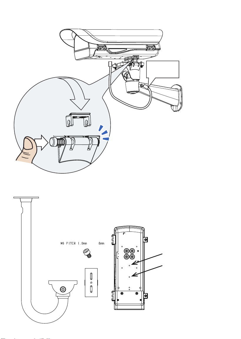
If using the AM-21E wall-mount bracket, secure the intersection bracket to the bottom
of the housing by driving two screws.
AM-11F
AM-811
AM-21D
AM-21E
Below are the mounting hole dimensions for the mounting brackets. Chances are you may
need to plan for the locations of the brackets.
16
If using other mount brackets, use the included M6 screws to secure the housing to the
bracket. Use the mounting holes indicated below.
x2
thread
Safety
tether wire
8.
Install the housing to the wall-mount bracket by aiming and pressing the spring mortise,
and hook the bracket onto the groove in the spring mortise.
Secure the T30 anti-tamper screws
on the other side using the included
L-wrench.
Connect the included safety wire
between enclosure and bracket.

17
English
The AM-21D wall-mount, AM-11F, and AM-811 pendant brackets use the two mounting
holes as indicated below.
AM-21D
AM-11F
AM-811
Another two mounting holes in the front can be used use an IR bracket, AM-219. The
bracket can be used to install external IRs.
AM-219

18
9.
Adjust zoom and focus and open a web console with the camera to tune for the best image. When
zoom and focus is done, Close the top cover and fasten the top cover screws.
The housing can also be installed using the pole-mount or corner-mount options along with a power box
(AA-351, AA-352), outdoor PoE switch, or junction box.
CaMate IR illuminators
If external IRs are installed, you can contact VIVOTEK for a different type of waterproof connectors for
the 1/2" conduits. You can then route two of the conduits through the opening in the front of the bracket
to the corresponding connectors on the IR illuminators. The 24V power wires to the IR illuminators are
contained within.

19
English
Use the included M10 hex socket screws to secure the power box to a pole-mount or corner mount
bracket.
M10
3/4” conduit
AM-314
AM-315
AM-414
AM-21D
AM-21E
Box:
AA-351
AA-352
AM-718
Outdoor PoE switch:
AW-GEU-083A-240
AW-GET-083A-120
AW-GET-123A-240
AW-GEU-086A-240
AW-GET-086A-120
AW-GET-126A-240
Speed Dome:
SD9361/62/63/64/65/66
SD83xx
AM-212/221/220/21C
The mounting hole denition is illustrated below. The same mounting hole pattern apply to all pole-
mount and corner-mount brackets.

20
AM-21D
AM-21E
If a power box or outdoor PoE switch is applied, Use the following mounting positions for the camera
housings (via AM-21D and AM-21E).
10.
If an IR illuminator is preferred, remove the metal cover from underneath the housing.
Install the IR unit (AI-106, -108, -109) by fastening 4 T30 anti-tamper screws. Note that the
bubber gasket should be in place when you install the unit.

21
English
11.
Firmware congurable options:
Open a web console with the camera.
Use the Media > Focus function to tune for a best image focus on your target area.
If preferred, e.g., shooting fast moving vehicles, select the 60fps frame rate.

22
In the night mode, check if the input signals are correctly detected. You may simulate the
night mode by blocking the IR unit's light sensor. Change the triggering parameters when
necessary.
Make sure that external IR is turned on in the night mode, and that the IR cut lter option is
synchronized with the digital input you connected.

23
English
Appendix: RS485 Commands
VI
For housings that come with IR illuminators, wiper, and washer, commands can be
delivered via the RS485 protocol. The RS485 connection uses the Pelco D protocol.
Conguration parameters:
Baud rate 2400
Data bits 8
Parity None
Stop bit 1
Command format:
Byte1 Byte2 Byte3 Byte4 Byte5 Byte6 Byte7
Sync Addr CMND1 CMND2 DATA1 DATA2 CKSM
Addr range: 0x00 ~ 0xFE. CKSM: check sum is the last 8 bits of the sum of Byte2 through
Byte6.
Command Group 1:
Command Description Command (hexadecimal, "ox" is
ommited)
Note
VaIR Lens Stop FF 01 00 00 00 00 01 Pelco D - Zoom Stop
VAIR Lens Wide FF 01 00 40 00 00 41 Pelco D - Zoom Wide
VaIR Lens Tele FF 01 00 20 00 00 21 Pelco D - Zoom Tele
Wiper On FF 01 00 09 00 01 0B Pelco D – Aux 1 On
Wiper Off FF 01 00 0B 00 01 0D Pelco D – Aux 1 Off
Wiper and Washer On FF 01 00 09 00 02 0C Pelco D – Aux 2 On
Wiper and Washer Off FF 01 00 0B 00 02 0E Pelco D – Aux 2 Off
IR Led Force On FF 01 00 09 00 03 0D Pelco D – Aux 3 On
IR Led Force Off FF 01 00 0B 00 03 0F Pelco D – Aux 3 Off
Command Group 2:
Command Name Command (hexadecimal, ox
is ommited)
Note
Addr conguration FF 01 00 18 01 dd CKSM dd: 0x00 ~ 0xFE; for example, when addr
is 2, the command looks like FF 01 00 18
01 02 1C
IRMode FF 01 00 18 02 mm CKSM mm: IR mode
mm=0x02: Light Sensor Auto (Default)
mm=0x03: DI Trigger
mm=0x04: via RS485 Command
(When receiving IR Led Force On / IR Led
Force Off command, will switch to using
the IR Mode -RS485 Command)
24
For example,
IRmode_Auto
FF 01 00 18 02 02 1D
IRmode_DI
FF 01 00 18 02 03 1E
IRmode_CMD
FF 01 00 18 02 04 1F
LightSensorGate FF 01 00 18 03 LL CKSM When the IR Mode Light Sensor Auto,
the Lux value to turn IR LED can be
congured.
LL: Lux, changes is made by
every10Lux
For example:
LightSensorGate = 100
FF 01 00 18 03 0A 26
LightSensorGate = 200
FF 01 00 18 03 14 30
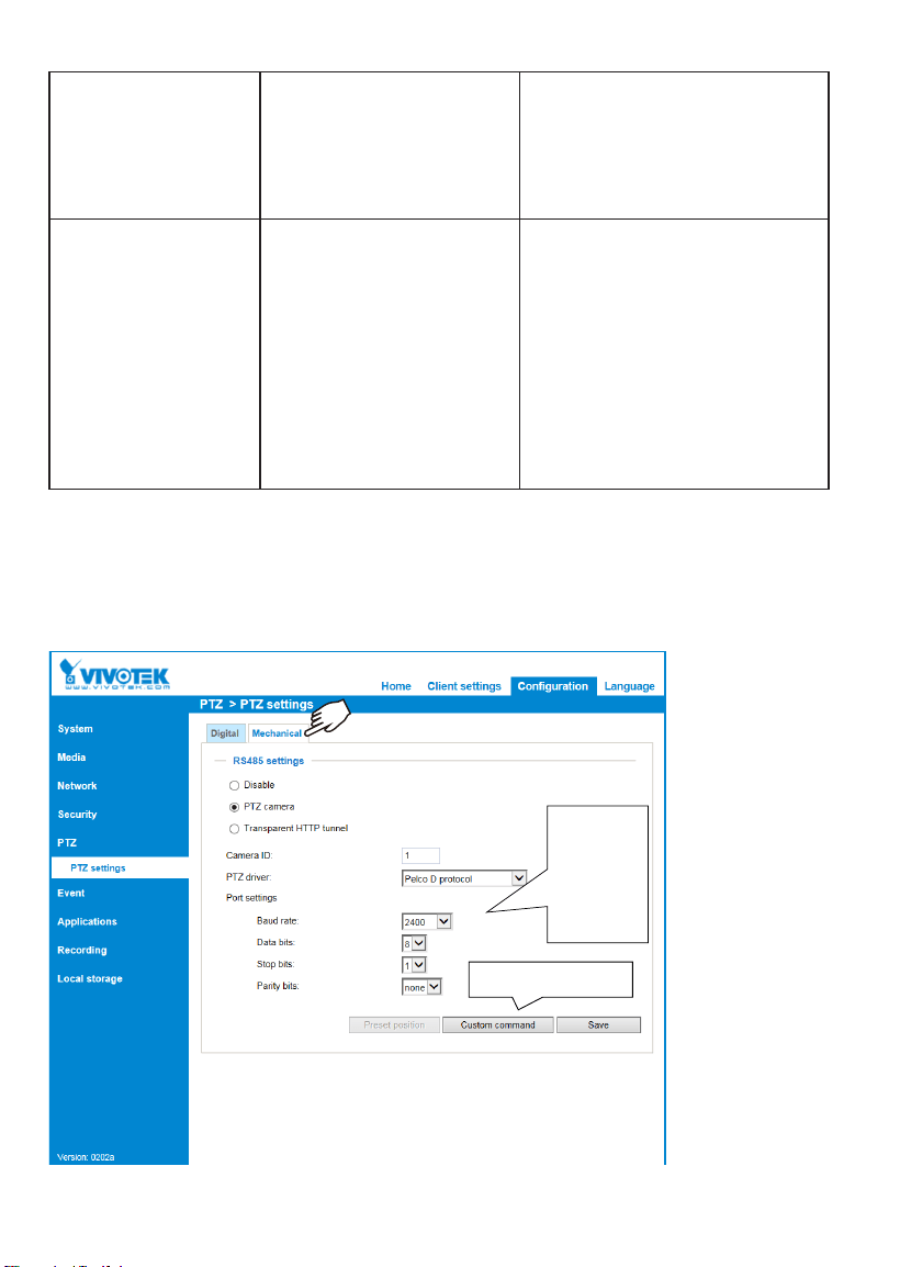
The parameters of IR illuminator can be controlled via the RS485 connection. You can
enable the connection in
Conguration
>
PTZ
>
Mechanical
window. Select the defaults
for the IR illuminator: Pelco D, baud rate - 2400, Data bits - 8, Stop bit - 1, Parity - none.
Defaults for IR:
Pelco D
2400
8
1
none
Customizable IR control

25
English
VaIR Lens Stop
VAIR Lens Wide
FF 01 00 00 00 00 01
FF 01 00 40 00 00 41
VaIR Lens Tele
Wiper On
Wiper Off
FF 01 00 20 00 00 21
FF 01 00 09 00 01 0B
FF 01 00 0B 00 01 0D
You can create custom command buttons by entering the Button name and the command
itself:
VaIR: The VAIR control include those on the IR Led and VaIR Lens.
There are 3 IR mode commands
IRMode = Light Sensor Auto (Default)
sensor lux reading < LightSensorGate - LED On
sensor lux reading >= (LightSensorGate + 10 Lux ) - LED Off
IRMode = DI_1 Trigger (IR triggered on by DI
DI _1 shorted DI –(Low) - LED On
DI_1 open (High) - LED Off
IRMode = controlled by RS485 Command (Pelco D – Aux 3 On/Off)
IR Led Force On - LED On
IR Led Force Off - LED Off
DO_1 as IR Status Feedback
LED On, DO_1 is grounded via MOSFET (DI- connected)
LED Off, DO_1 no input
VaIR Lens Zoom control
Dip Switch
4 congurations using the Dip Switch on the distribution board.
When Lens stops, its last position will be memoried,and when powered on again, lens will move to the
previous position. When powered on for the rst time, Lens will follow the DIP switch conguration.
Wiper & Wahser control)
DI_2 Trigger:
When DI_2 connected to DI- (Low), wiper and washer operate for 3 times and then stop.
Using RS485 Command –Wiper Only (Pelco D – Aux 1 On/Off)
Wiper On, wiper takes action
Wiper Off, wiper starts one operation and then stops.
RS485 Command –Wiper & Washer (Pelco D – Aux2 On/Off)
Wiper and Washer On, pumps and spray water with wiper action.
Wiper and Washer Off, spraying and wiping starts one operation and then stops.
DO2 used for spraying control
DO_2 connected to DI- via MOSFET - starts spraying.
Spraying stops, and the LED turns Off when DO_2 is not triggered.

26
This page is intentionally left blank.