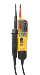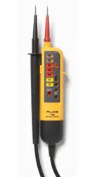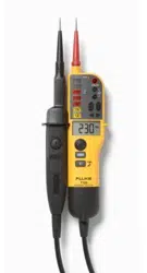

T90/T110/T130/T150
Voltage/Continuity Tester
Instruction Sheet
Introduction
The Fluke T90/T110/T130/T150 Electrical Testers (the
Tester or Product) are voltage and continuity testers
witharotaryeldindication(T110/T130/T150only).
Their primary use is for test and measurement in
industrial,commercial,andhouseholdenvironments.
This Product complies with the most recent safety
standardsforsafe,reliabletestandmeasurement.
Thexedtestprobecoverpreventstheriskofinjury
whenyoumovetheinstrument.
How to Contact Fluke
To contact Fluke, call one of the following telephone
numbers:
• Germany: 07684 - 80 09 545
• France: 01 48 17 37 37
• United Kingdom: +44-0-1603256600
Go to www.uke.com to register your product,
downloadmanuals,andndmoreinformation.
To view, print, or download the latest manual
supplement, visit http://us.uke.com/usen/support/
manuals.
Safety Information
Warning
Topreventpossibleelectricalshock,�re,or
personal injury:
● Read all safety Information before you use the
Product.
● UsetheProductonlyasspeci�ed,orthe
protection supplied by the Product can be
compromised.
● Measureaknownvoltage�rsttomakesure
that the Product operates correctly.
● Do not apply more than the rated voltage,
between the terminals or between each
terminal and earth ground.
PN 3928132
● Limitoperationtothespeci�edmeasurement
category or voltage ratings.
● Do not work alone.
● Comply with local and national safety codes.
Use personal protective equipment (approved
rubbergloves,faceprotection,andame-
resistant clothes) to prevent shock and arc
blast injury where hazardous live conductors
are exposed.
● Do not use the Product around explosive gas,
vapor, or in damp or wet environments.
● Do not use and disable the Product if it is
damaged.
● Do not use the Product if it operates
incorrectly.
● Keep�ngersbehindthe�ngerguardsonthe
probes.
● Do not use the Product if the test leads are
damaged.
● Examine the case before you use the Product.
Look for cracks or missing plastic.
● The battery door must be closed and fastened
before you operate the Product.
● Replace the batteries when the low battery
indicator shows to prevent incorrect
measurements.
● Repair the Product before use if the battery
leaks.
● For use by competent persons. Anyone
using this Product should be knowledgeable
and trained about the risks involved with
measuring voltage, especially in an industrial
setting, and the importance of taking safety
precautions and of testing the Product before
and after using it to ensure that it is in good
working condition.
Symbols
These symbols are on the Tester or in this instruction
sheet.
Symbol Explanation
Importantinformation.Consultthe
instructionsheet.
HazardousVoltage.
Suitableforliveworking.
Conforms to European Union Directives
CAT III Measurement Category III is applicable to
test and measuring circuits connected to
the distribution part of the building’s low-
voltageMAINSinstallation.
CAT IV Measurement Category IV is applicable
to test and measuring circuits connected
at the source of the building’s low-voltage
MAINSinstallation.
1.888.610.7664 sales@GlobalTestSupply.com
Fluke
-
D
irect
.com
Symbol Explanation
This product complies with the WEEE
Directive (2002/96/EC) marking
requirements.Theaxedlabelindicates
that you must not discard this electrical/
electronic product in domestic household
waste.ProductCategory:Withreference
to the equipment types in the WEEE
DirectiveAnnexI,thisproductisclassed
as category 9 "Monitoring and Control
Instrumentation"product.Donotdispose
of this producat as unsorted municipal
wast.TotoFluke'swebsiteforrecycling
information.
Accessories
TheTesterissuppliedwithaccessories.
Part Number Accessory
4083642 GS38 Probe Tip Sheath
4083656 4 mm ∅ProbeExtensions
4111533 H15 Belt Holster (sold separately)
4111540
C150 Zippered Soft Carrying Case
(sold separately)
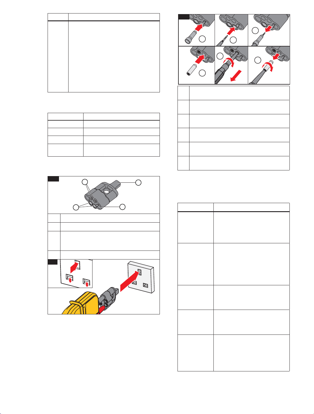
Figure1showstheProbeTipProtectorCap.This
multifunctional accessory is useful for tests and
storageofdi�erentaccessories.
Storage area for Probe Tip Sheaths
Storage area for 4 mm ∅ProbeExtensions
Earth-pin safety-socket opener for UK
sockets (press opener into socket to release
safety covers, see Figure 2)
Storage area for probes when not in use
2
Figure 3 illustrates how to store and retrieve the tip
accessoriesfromthecap.
1
4
3
1
2
Quick Reference
Usethepushbuttonstoturnthefunctionsonoro�.
See the list that follows for a quick reference to each
ofthesepushbuttons.
Pushbutton Description
c
Pushtoturntorchlightonoro�
(T110,T130,T150).
To save battery power the
functionautomaticallyturnso�
after30seconds.
I
Push to hold the value that shows
in the LCD in volt and resistance
measurements.Pushagainto
turnHOLDo�(T130,T150).
To save battery power the
functionautomaticallyturnso�
after30seconds.
h
Push this button on each of
the probes at the same time to
start the test for low impedance
switchableload.
cp
Push and hold for 2 seconds to
turnthebeeperonoro�.The
status shows on the LCD (T150,
T130)orwiththeLED(T110).
Il
Push and hold for 2 seconds to
turn the resistance measurement
onoro�(T150only).
To save battery power, the
functionautomaticallyturnso�
after30seconds.
For storage, push Probe Tip Sheath into
place.
Toretrieve,rmlypushprobetipintoProbe
TipSheath.
Pull on probe handle to remove Probe Tip
Sheath.
For storage, push 4 mm ∅ProbeExtensions
intoplace.
Toretrieve,rmlypushprobetipintoProbe
Extensions.Twist1/4turn.
Pull on probe handle to remove Probe
Extensions.Continuetotwistuntiltipistight.
3
1
4
2
5
1/4
3
6
1.888.610.7664 sales@GlobalTestSupply.com
Fluke
-
D
irect
.com

Features
Model
T90 T110 T130 T150
Complies with EN 61243-3:2014
• • • •
LED Indication Range: 12 V to 690 V dc and ac
• • • •
V Display: Multiple LED Bargraph
• • • •
Independent ELV indicator LED, indicates if >50 V ac/120 V dc is present even in
the event of no battery power or main circuit failure
• • • •
LCD Indication Range: 6 V to 690 V dc and ac
• •
V Display: Digital LCD 3½ digit (1 V resolution)
• •
ResistanceMeasurement:LCD3½digit(0to1999Ω/1Ωresolution)
•
LCD Backlight
• •
Display HOLD: Freeze/unfreeze display with voltage or resistance measurement
• •
CATII690V/CATIII600V
•
CATIII690V/CATIV600V
• • •
Rugged, Double-Insulated Wire
• • • •
FixedImpedance~200kΩ(~3.5mA@690V)
• • • •
SwitchableLoadby2pushbuttons(30mA@230V)
• • •
Vibration During Load (when 2 switchable load pushbuttons are pushed)
• • •
Single-Pole Phase Test (also operates with gloves)
• • • •
Rotary Field Direction (also operates with gloves)
• • •
Continuity Test / Diode Test
• • • •
Torch
• • •
BeeperforContinuity/Phase/ACV(switchable)
• • •
BeeperforContinuity/Phase/ACV(nonswitchable)
•
IP54
•
IP64
• • •
Slim Metal Probe Tips (threaded base for included tip accessories)
• • • •
Probe Tip Protector Cap (secure storage for the docked probes)
• • • •
4 mm ∅ProbeTipThicknessExtensions(forbettertinoutlets)
• • • •
19 mm Probe Tip distance when docked
• • • •
ProbeTipSheath(UKGS38sheath–keepstheexposedmetaltoa<4mmlimit)
• • • •
Slim Probe for Ultra-Compact Form Factor
•
1.888.610.7664 sales@GlobalTestSupply.com
Fluke
-
D
irect
.com
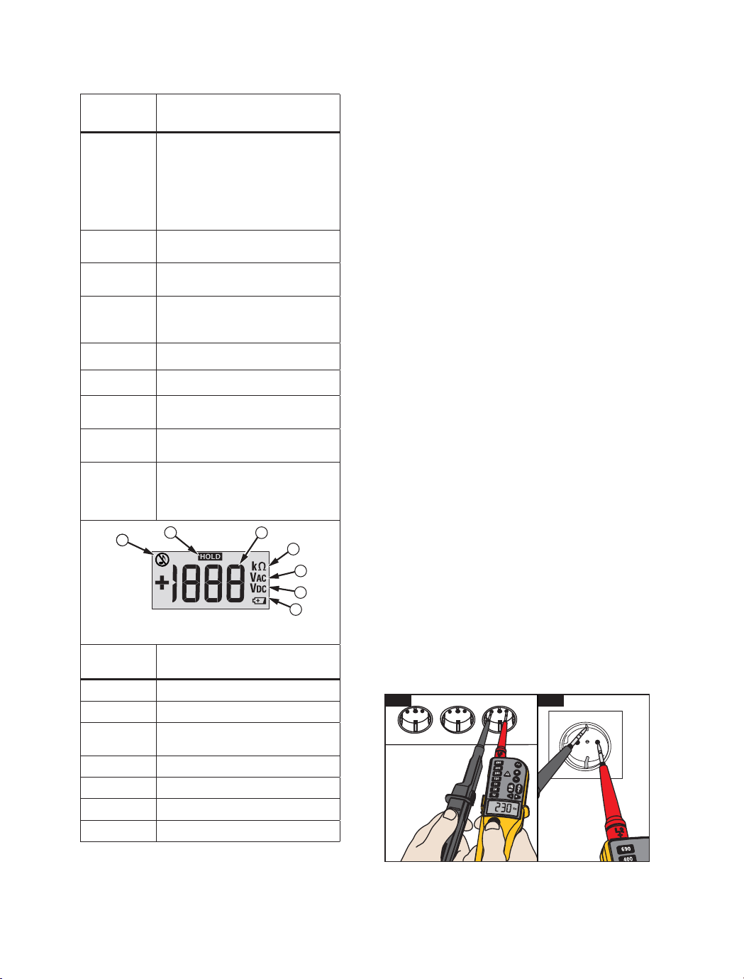
Display
LEDs
(All Models)
Description
y
x
w
v
u
t
s
Voltage level is backlit
z
Voltage level is more than ELV
limit (>50 V ac or >120 V dc)
a
Voltage is ac / phase in Single
Pole Phase test
d
DC
e
Voltage is positive or negative at
the indicator probe
b
Battery is low / Replace battery
M
Silent mode (T110)
f
Continuity or diode in forward
operation
g
Switchable load is ON (two buttons
pressedandcurrentows)
qr
3-phase sequence indication
detected left or right turning
phases with nonindicator probe
(L1) to indicator probe (L2)
1
2
4
3
5
6
7
gpn06.eps
LCD
(T130/T150)
Description
Silent mode (T130/T150)
Display is in HOLD mode
Voltage measurement (T130/T150)
or resistance measurement (T150)
Resistance measurement (T150)
ACVoltagemeasurement
DC Voltage measurement
Battery is low / Replace battery
How to Hold the Tester
Alwaysholdtheproductbehindthebarriertokeepthe
displayinview.SeeFigure4.
Warning
To prevent possible electric shock, never
touch the metal pins of the probes when
power is applied.
Self-Test
TheTesterhasabuilt-inselftestfunction.
Before and after use, do a self-test:
1. Touchandholdtheprobetipstogether.
f
shows and you can hear the beeper (when
activeontheT110/T130/T150).Or,inthe
silent mode, the LED is on (when active on the
T110).Thismakessurethatthetestleadshave
continuity.
2. Make sure that:
• batteries are good
•
b
(T90, T110) is NOT on
•
B
(T130, T150) does not show in the
display
3. Continue to hold the probe tips together for more
thanthreeseconds.
4. Opentheprobetipsagain.AllLEDs(allbut
z
and
g
) must be on and all symbols in the LCD (T130,
T150)showforonesecond.Thistestmakessure
that all other internal circuits and indicators are
good.
5. Measure a known voltage such as a 230 V socket
outlet.Thiscompletestheself-testandincludes
the >ELV circuit.
If the Tester fails the self-test or voltage test, do not
use.SeeTo Contact Flukeforservice.
For an inspection of the insulation, cables, and case,
see Safety Information.
4
5
1.888.610.7664 sales@GlobalTestSupply.com
Fluke
-
D
irect
.com
Resistance Test (T150)
The Tester measures low ohm resistances between
1 Ωand 1999 Ω at a resolution of 1 Ω.
To do a resistance test:
1. DoaVoltagetesttomakesuretheUUTisnotlive.
2. ConnectthetwotestprobeswiththeUUT.Push
and hold
Il
for 2 seconds and read value
onthedisplay.
3. Push and hold
Il
for 2 seconds to turn the
functiono�.
To save battery power the function automatically
turnso�after30seconds.TheTesterautomatically
goes into the voltage measurement mode if voltage
issensed.
Display HOLD
(T130/T150)
The T130 and T150 include a Display HOLD function
fortheLCD.
To use the Display HOLD function:
1. Push HOLD to freeze the LCD while in a Voltage
orResistancemeasurement.Thestatusisshown
inthedisplaywithaHOLDsymbol.
2. PushHOLDagaintounfreezetheLCD.
To save battery power the Display HOLD function
automaticallyturnso�after30seconds.
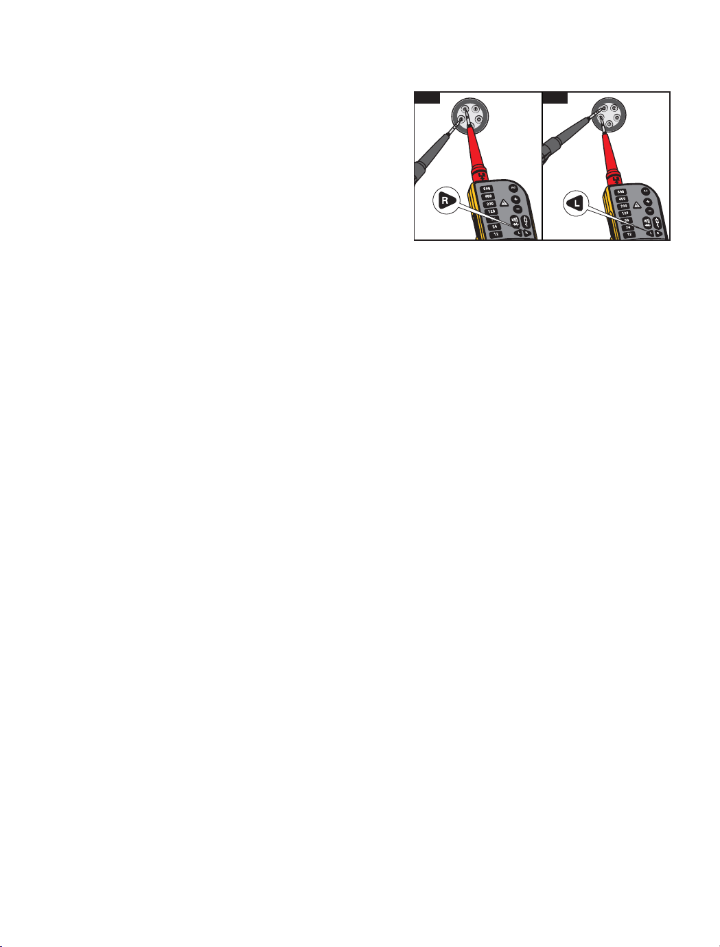
Rotary Field Indication
(T110/T130/T150)
TheTesterhasadouble-polerotaryeldindicator.
The 3rd pole is capacitively-coupled into the unit from
theuser’shand.TheTesteroperateswithoutatouch
electrodeandisalsousablewhenyouweargloves.
q
and
r
display for ac voltage measurements,
but the rotary direction is found only in a three-phase
system.Inparallel,theTesterreadsthevoltage
betweentwoexternalconductors.
Tousetherotaryeldindicator:
1. Connect the test probe with the phase L1 and the
indicatorprobewiththephaseL2.
2. Firmly hold the indicator probe around its body
(betweenthengerguardandcable).
Thevoltageandtherotaryelddirectionshowonthe
display.
r
(see Figure 6)
signiesthatthesupposed
phase L1 is the actual phase L1 and the supposed
phaseL2istheactualphaseL2rightrotaryeld.
q
(seeFigure7)signiesthatthesupposedphase
L1 is the actual phase L2 and the supposed phase L2
istheactualphaseL1leftrotaryeld.Aretestwith
exchangedtestprobeswillcausetheoppositesymbol
toilluminate.
Torch and Backlight
(T110/T130/T150)
The T110/T130/T150 include a torch and backlight
function.Thisfunctionishelpfulinareaswith
unsatisfactorylight,forexample,divisionswitch
cabinets.
To use the torch or backlight:
1. Push
c
toturnthetorchandbacklighton.
2. Push
c
againtoturnthetorchandbacklighto�.
To save battery power the function automatically turns
o�after30seconds.
Maintenance
Warning
For safe operation and maintenance of the
product:
● Be sure that the battery polarity is correct to
prevent battery leakage.
● Remove batteries to prevent battery leakage
and damage to the Product if it is not used for
an extended period or if it is stored above or
below its operating temperature.
● Do not disassemble the Product beyond
removal of the battery door.
● Repair the Product before use if the battery
leaks.
Warning
To prevent personal injury:
● Batteries contain hazardous chemicals that
can cause burns or explode. If exposure to
chemicals occurs, clean with water and get
medical aid.
● Have an approved technician repair the
Product.
● Remove the input signals before you clean the
Product.
● Useonlyspeci�edreplacementparts.
● Keep the Tester dry and clean.
● Do not operate the Product with covers
removed or the case open. Hazardous voltage
exposure is possible.
6
7
1.888.610.7664 sales@GlobalTestSupply.com
Fluke
-
D
irect
.com

Voltage Test
AvoltagetestisthemainfunctionoftheTester.The
T90 and T110 have an LED bargraph indication to
showthenominalvoltagelevels.TheT130andT150
alsoshowthevaluesintheLCD.
Connect the two test probes to the UUT to do a
voltagetest.
Above12VtheTesterturnsonautomatically.Forthe
T130andT150,theLCDcomesonat6V.Thebacklit
LEDsshowthenominalvoltagelevel,forexample
v
or
w
.
For the T130 and T150, the voltage is measured
andthevalueisshownontheLCDasforexample,
227j
.
The voltage value on the LCD must not be used to
validateazerovoltage.AlwaysusetheLEDbargraph.
For ac voltages, the
a
LED and the
j
symbol in
theLCD(T130/T150)illuminates.Fordcvoltages,the
polarity of the display voltage refers to the instrument
test probe with the
D
and
E
LEDs or the
+
or
-
symbolintheLCD(T130/T150).Forvoltagesthat
are more than the ELV limit (>50 V ac or >120 V dc),
z
comesoninthedisplay.ThevoltageLED
bargraph and the >ELV indicator must not be used for
measurements.Formeasurementsyoucanusethe
LCDontheT130/T150toseetheactualvalue.
When the LED bargraph does not indicate the
presence of voltage (no LEDs illuminated), Fluke
highly recommends that you install earthing
equipmentbeforework.
Voltage Test with Switched Load, RCD
Trip Test (T110/T130/T150)
During voltage tests, you can decrease the
interference voltages from inductive or capacitive
coupling by loading the UUT with a lower impedance
thantheTesterhasinnormalmode.Insystemswith
RCD circuit breakers, you can trip an RCD switch
with the same low impedance as when you measure
voltagebetweenLandPE(seeFigure5).
To do an RCD trip test during voltage measurement,
push the two
h
buttonsatthesametime.Ifyouhave
10mAor30mARCDsbetweenLandPEina230V
system,itwilltrip.
During load current, the indicator probe side vibrates
and the
g
LEDistheindicationfortheowingload
current.Thisindicationisnottobeusedforvoltage
testormeasurement.
Due to low impedance, this circuit is overload-
protected and will decrease the load current after
20seconds@230Vandafter2seconds@690V.
If the two pushbuttons are not used, the RCDs will not
Single-Pole Phase Test
To do a single-pole phase test:
1. Firmly hold the indicator probe around its body
(betweenthengerguardandcable).
2. Touchtheprobetiptoanunknowncontacttond
theconductor.
a
turns on when the ac voltage is >100 V and
youhearthebeeper(T110/T130/T150only).
Forasingle-polephasetesttondexternal
conductors, the display function operates unreliably
insomeconditions.Anexampleisinsulatedbody
protective equipment on insulated locations, such as a
PVCoororberglassladder.
The Tester operates without a touch electrode and is
usablewhenyouweargloves.Thesingle-polephase
testisnotmeanttondifaconductorisliveornot.
Forthisfunction,alwaysusetheVoltagetest.
Continuity/Diode Test
To do a continuity test of cables, switches, relays,
bulbs, or fuses:
1. DoaVoltagetesttomakesuretheUUTisnotlive.
2. ConnectthetwotestprobeswiththeUUT.Youwill
hear the beeper if it is on (T110/T130/T150 only)
for continuity and
f
ison.
The test voltage/current polarity for a diode test at the
non-indicator test probe is positive + and the indicator
test probe is negative -.
Note
The Tester automatically goes into the voltage
measurement mode if voltage is sensed.
Beeper (T110/T130/T150)
ForContinuity,ACVoltage,andSingle-PolePhase
Testmodes,youcanturnthebeeperonoro�:
1. Push and hold
cp
for 2 seconds to turn the
beeperon.
2. Push and hold
cp
for 2 seconds to turn the
beepero�.
The status shows together with Volt, Continuity, or
Single-PolePhaseindicationsintheLEDorLCD.
Thebeepermodeisstoreduntilyouchangeit.Always
do a continuity test (touch probe tips together) to
make sure that the beeper operates before you start
atest.
In work areas with high background noise, make sure
youcanhearthebeeperbeforeyoustartatest.
1.888.610.7664 sales@GlobalTestSupply.com
Fluke
-
D
irect
.com

Speci�cations
Model
T90 T110 T130 T150
LEDs
Voltage range 12 V to 690 V ac/dc
• • • •
Resolution
±12 V, 24 V, 50 V, 120 V,
230 V, 400 V, 690 V
• • • •
Tolerance
Complies with
EN 61243-3:2014
• • • •
Frequency range 0 / 40 Hz to 400 Hz
• • • •
Response time ≤0.5second
• • • •
Autopoweron ≥12 V ac/dc
• • • •
LCD
Voltage range 6 V to 690 V ac/dc
• •
Resolution ±1 V
• •
Tolerance ±(3 % rdg + 5 digits)
• •
Frequency range 0 / 40 Hz to 400 Hz
• •
Response time ≤1 second
• •
Autopoweron ≥6 V ac/dc
• •
Voltage detection Automatic
• • • •
Polarity detection Full range
• • • •
Range detection Automatic
• • • •
Internal basic load impedance
Peak current
Maximum3.5mAat
690 V 200 kΩ/Is<3.5mA
(no RCD tripping)
• • • •
Operation time
Duration Time =
30 seconds
• • • •
Recovery time
Recovery Time =
240 seconds
• • • •
Switchable Load ~7kΩ
• • •
Peak current Is(load)=150mA
• • •
RCD tripping I~30mA@230V
• • •
Continuity Test 0 to 400 kΩ
• • • •
Accuracy nominal resistance +50 %
• • • •
Test current ≤5 µA
• • • •
Single-polePhaseTest 100 V ac to 690 V ac
• • • •
Frequency range
40 Hz to 60 Hz
•
50 Hz to 400 Hz
• • •
Rotary Field Indication
• • •
Voltage range (LEDs)
100 V to 690 V
(phase to earth)
• • •
Frequency range 50 Hz to 60 Hz
• • •
Resistance Measurement 0 Ωto 1999 Ω
•
Resolution 1 Ω
•
Tolerance
±(5%rdg+10digits)@
20 °C
•
Temperaturecoecient ±5 digits / 10 K
•
Test current ≤30 µA
•
Size in mm (HxWxL) 245x64x28 255x78x35
Weight in kg (includes batteries) 0.18 0.27
1.888.610.7664 sales@GlobalTestSupply.com
Fluke
-
D
irect
.com

Environmental
Pollution degree.......................2
Protection degree.....................IP54 (T90)
IP64 (T110/T130/
T150)
Operating Temperature............-15 °C to +45 °C
Storage Temperature................-20 °C to +60 °C
Humidity...................................85%RHmaximum
Altitude.....................................2000 m
Vibration...................................refer to EN61243-3
SafetyEN61243-3:2014
Transporting goods...................VBG 1, § 35
Overvoltage protection.............690 V ac/dc
Measurement category
T90......................................CATII690V
CATIII600V
T110/T130/T150.................CATIII690V
CATIV600V
Power supply...............................2x1.5VMicro/
LR03/AAA
Power consumption
....................50mAmaximum/
~250mW
Language support.......................Czech, Dutch,
English, Finnish,
French, German,
Italian, Norwegian,
Polish, Portuguese,
Romanian,
Russian, Spanish,
Swedish, Turkish
1.888.610.7664 sales@GlobalTestSupply.com
Fluke
-
D
irect
.com
LIMITED WARRANTY & LIMITATION OF
LIABILITY
This Fluke product will be free from defects in material and
workmanshipfortwoyearsfromthedateofpurchase.This
warranty does not cover fuses, disposable batteries, or damage
from accident, neglect, misuse, alteration, contamination, or
abnormalconditionsofoperationorhandling.Resellersarenot
authorizedtoextendanyotherwarrantyonFluke’sbehalf.To
obtain service during the warranty period, contact your nearest
Fluke authorized service center to obtain return authorization
information, then send your defective Tester to that Service
Centerwithadescriptionoftheproblem.Replacedepleted
batteries immediately to avoid Tester damage from battery
leakage.
THISWARRANTYISYOURONLYREMEDY.NOOTHER
WARRANTIES,SUCHASFITNESSFORAPARTICULAR
PURPOSE,AREEXPRESSEDORIMPLIED.FLUKEISNOT
LIABLEFORANYSPECIAL,INDIRECT,INCIDENTALOR
CONSEQUENTIALDAMAGESORLOSSES,ARISINGFROM
ANYCAUSEORTHEORY.Sincesomestatesorcountriesdo
notallowtheexclusionorlimitationofanimpliedwarrantyorof
incidental or consequential damages, this limitation of liability
maynotapplytoyou.
FlukeCorporation FlukeEuropeB.V
P.O.Box1186
5602B.D.
Eindhoven
The Netherlands
How to Clean
Before you clean the Tester, remove it from all
measurementcircuits.
Caution
To prevent damage, do not use abrasives or
solvents on the Tester.
Cleanthecasewithamoistclothandweakdetergent.
AfteryoucleantheTester,donotuseitforaperiod
of5hours.
When to Calibrate
Flukerecommendsacalibrationintervalof1year.
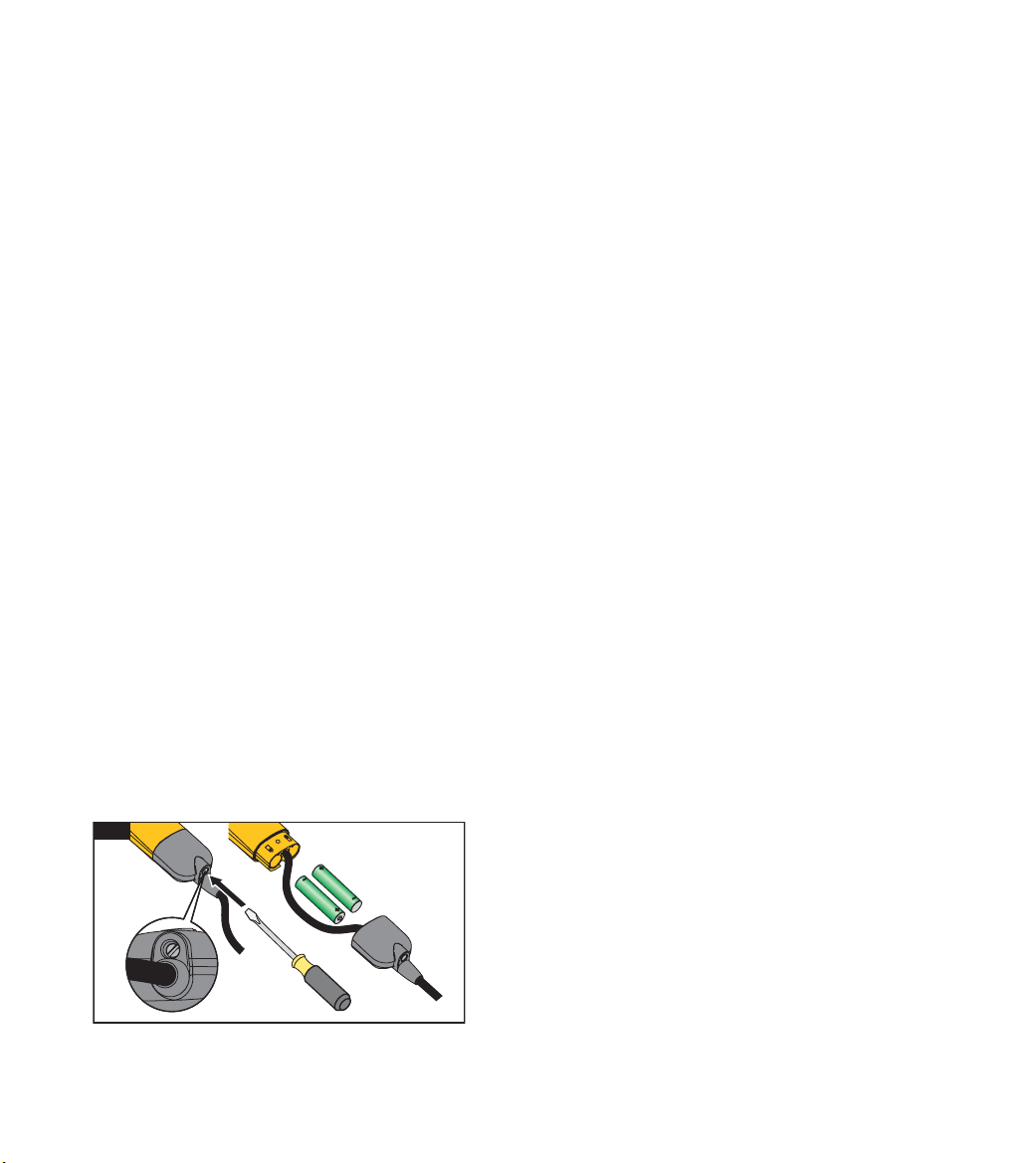
Battery Replacement
If
b
(Fluke T90/T110) is on or
B
shows
in the LCD (Fluke T130/T150) during tests or
measurements,replacethebatteries.
To replace the batteries:
1. Disconnect the Tester from the measurement
circuit.
2. Openthebatterycover.SeeFigure8.
3. Removethedischargedbatteries.
4. Replacewithtwonew1.5VIECLR03AAA
batteries.
5. Alignthebatterypolarityasshownonthecase
housing.
6. Closeandattachthebatterycover.
Note
Do not overtighten the screw for the battery cover.
7. Completeaself-test.
8
1.888.610.7664 sales@GlobalTestSupply.com
Fluke
-
D
irect
.com