Loading ...
Loading ...
Loading ...
15
8. Testrun
Step5 Stopthetestrun.
1Pressthe[ON/OFF]buttontostopthetestrun.(TheTestrunmenuwillappear.)
Note:Ifanerrorisdisplayedontheremotecontroller,seethetablebelow.
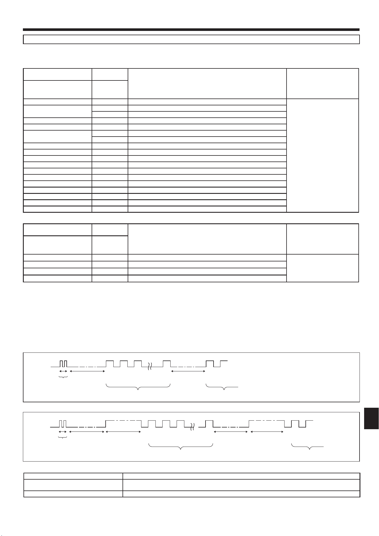
[OutputpatternA] Errorsdetectedbyindoorunit
Wirelessremotecontroller
Wiredremote
controller
Symptom Remark
Beepersounds/OPERATION
INDICATORlampblinks(Num-
beroftimes)
Check code
1 P1 Intake sensor error
2
P2 Pipe(TH2)sensorerror
P9 Pipe(TH5)sensorerror
3 E6,E7 Indoor/outdoorunitcommunicationerror
4 P4 Drainsensorerror/Floatswitchconnectoropen
5
P5 Drain pump error
PA Forced compressor error
6 P6 Freezing/Overheatingprotectionoperation
7 EE Communication error between indoor and outdoor units
8 P8 Pipetemperatureerror
9 E4 Remotecontrollersignalreceivingerror
10 — —
11 PB(Pb) Indoor unit fan motor error
12 FB(Fb) Indoorunitcontrolsystemerror(memoryerror,etc.)
14 PL Refrigerant circuit abnormal
No sound E0,E3 Remote controller transmission error
No sound E1,E2 Remote controller control board error
No sound – – – – No corresponding
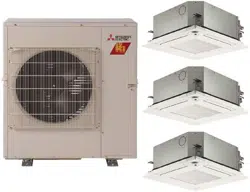
[OutputpatternB] Errorsdetectedbyunitotherthanindoorunit(outdoorunit,etc.)
Wirelessremotecontroller
Wiredremote
controller
Symptom Remark
Beepersounds/OPERATION
INDICATORlampblinks(Num-
beroftimes)
Check code
1 E9 Indoor/outdoorunitcommunicationerror(Transmittingerror)(Outdoorunit)
Fordetails,checktheLED
display of the outdoor controller
board.
2 UP Compressorovercurrentinterruption
3 U3,U4 Open/shortofoutdoorunitthermistors
14 PLorOthers
Abnormalityofrefrigerantcircuitorothererrors
*1Ifthebeeperdoesnotsoundagainaftertheinitial2beepstoconrmtheself-checkstartsignalwasreceivedandtheOPERATIONINDICATORlampdoesnotcomeon,
there are no error records.
*2Ifthebeepersounds3timescontinuously“beep,beep,beep(0.4+0.4+0.4sec.)”aftertheinitial2beepstoconrmtheself-checkstartsignalwasreceived,thespeci-
edrefrigerantaddressisincorrect.
• Onwirelessremotecontroller
Thecontinuousbuzzersoundsfromreceivingsectionofindoorunit.
Blink of operation lamp
• Onwiredremotecontroller
Check code displayed in the LCD.
• Refertothefollowingtablesfordetailsonthecheckcodes.(Wirelessremotecontroller)
OPERATIONIN-
DICATOR lamp
blinking pattern
Beep Beep Beep Beep Beep Beep Beep
Off
Approx.2.5sec.
On
Approx.3sec.
On
0.5 sec.
On
0.5 sec.
On
0.5 sec.
On
0.5 sec.
Off
Approx.2.5sec.
On
Approx.3sec.
On
0.5 sec.
On
0.5 sec.
···Repeated
Number of blinks/beeps in pattern indicates the check
codeinthefollowingtable(i.e.,n=5for“U2”)
Numberofblinks/beepsinpatternindicatesthe
check code in the following table
n
th
1
st
2
nd
3
rd
1
st
2
nd
Self-check
starts
(Startsignal
received)
Beeper sounds
[OutputpatternB]
OPERATIONIN-
DICATOR lamp
blinking pattern
Beep
Beep Beep Beep Beep Beep Beep
Off
Approx.2.5sec.
On
0.5 sec.
On
0.5 sec.
On
0.5 sec.
On
0.5 sec.
Off
Approx.2.5sec.
On
0.5 sec.
On
0.5 sec.
···Repeated
Number of blinks/beeps in pattern indicates the check
codeinthefollowingtable(i.e.,n=5for“P5”)
Numberofblinks/beepsinpatternindicatesthe
check code in the following table
n
th
1
st
2
nd
3
rd
1
st
2
nd
Self-check
starts
(Startsignal
received)
Beeper sounds
[OutputpatternA]
SeethetablebelowforthedetailsoftheLEDdisplay(LED1,2,and3)ontheindoorcontrollerboard.
LED1(microcomputerpowersupply) Indicateswhethercontrolpowerissupplied.MakesurethatthisLEDisalwayslit.
LED2(remotecontrollerpowersupply)
Indicates whether power is supplied to the wired remote controller. The LED is lit only for the indoor unit that is connected
to the outdoor unit that has an address of 0.
LED3(indoor/outdoorunitcommunication) Indicateswhethertheindoorandoutdoorunitsarecommunicating.MakesurethatthisLEDisalwaysblinking.
Note:
Iftheunitisoperatedcontinuouslyduringatestrun,theunitstopsafter2hours.
Loading ...
Loading ...
Loading ...