Loading ...
PLEASE READ AND SAVE THESE
IMPORTANT SAFETY INSTRUCTIONS
FEATURES - OPERATIONS
FEATURES - OPERATIONS FEATURES - OPERATIONS
6. Pull the power cord through the center hole of the
assembled base. Align marking “B”, located at the
center hole of the assembled base, with marking “B”
at the bottom end of the pedestal. Insert the
alignment post from the pedestal into the alignment
hole on base for proper alignment (Fig. 6).
7. Use 4 screws (M4x10mm) provided to attach the
assembled base to the pedestal. Secure the screws
with a screwdriver (Fig. 7).
8. Wind the power cord underneath the base. Secure the
power cord through the cord clips (Fig. 8).
9. Turn fan right side up and place on a dry and level
surface before operating.
OPERATING INSTRUCTIONS (SEE FIG. 9, 10)
A. Power
Press
= On, Off
B. Speed Settings
Press = 1, 2, 3, 4, 5
C. Timer Control
Press
= Turns Off in 2, 3 hours
D. Oscillation Control
Press
= Oscillation On, Off
E. Natural Breeze, Sleep Breeze MODE
Press
MODE = Natural Breeze, Sleep Breeze
Natural Breeze Mode
will cycle through the fan
speed settings randomly.
Sleep Breeze Mode
will cycle through the fan
speed settings in order.
NOTE: Your fan features LED panel. When a specific
feature is activated on your fan, a corresponding LED
indicator light will illuminate showing which features
have been activated.
ASSEMBLY INSTRUCTIONS
Assembly Time: 10-15 minutes.
Tools Required: Phillips head screw driver.
NOTE: MAKE SURE YOU REMOVE ALL CONTENTS FROM
THE PACKAGE. PLEASE CHECK PACKAGING MATERIALS FOR
PARTS THAT COULD BE REQUIRED TO OPERATE YOUR FAN.
LOCATE THE BELOW PARTS FROM THE BOX TO PREPARE
FOR ASSEMBLY:
• Fan housing
• 2 pedestal halves
• 2 base halves
• 8 M4x10mm screws (4 pcs for pedestal assembly
and 4 pcs for base assembly)
• Remote Control
Follow the steps below in order to assemble the fan
pedestal and base before operating your fan:
1. To assemble the pedestal, simply snap the 2 pedestal
halves together (Fig. 1).
2. Pull the power cord through the assembled pedestal,
making sure the wider end of the pedestal is facing
towards the fan housing (Fig. 2).
3. Align marking “A”, located at the bottom of the fan
housing, with marking “A” on the top end of the
pedestal. Insert the alignment post from the pedestal
into the alignment hole on fan housing for proper
alignment (Fig. 3).
4. Use 4 screws (M4x10mm) provided to attach the
assembled pedestal to the bottom of the fan housing.
Secure the screws with a screwdriver (Fig. 4).
5. Snap the 2 base halves together by sliding the posts
of one base half into the slots of the second base half
(Fig. 5).
When using electrical appliances, basic safety precautions
should always be taken including the following:
1. Read all instructions before using this appliance.
2. Use fan only for purposes described in the instruction
manual.
3. To protect against electrical shock do not immerse
unit, plug or cord in water or spray with liquids and
plug the appliance directly into a 120V AC electrical
outlet.
4. Close supervision is necessary when any appliance is
used by or near children.
5. Unplug from outlet when not in use, when moving
fan from one location to another, before putting on
or taking off parts and before cleaning.
6. Avoid contact with moving parts.
7. Do not operate in the presence of explosive and/or
flammable fumes.
8. To avoid fire hazard, NEVER place the cord under
rugs or any parts near an open flame, cooking or
other heating appliance.
9. Do not operate any appliance with a damaged cord
or plug after the appliance malfunctions, or has been
dropped/damaged in any manner. Discard fan or
return to an authorized service facility for
examination and/or repair.
10. Do not run cord under carpeting. Do not cover cord
with throw rugs, runner, or similar coverings. Do not
route cord under furniture or appliances. Arrange
cord away from traffic area and where it will not be
tripped over.
11. The use of attachments not recommended or sold by
the appliance manufacturer may cause hazards.
12. Do not let the cord hang over the edge of a table,
counter or come in contact with hot surfaces or leave
exposed to high traffic areas.
13. Do not use outdoors.
14. To disconnect, grip plug and pull from wall outlet.
Never yank on cord.
15. Always use on a dry, level surface.
16. Do not operate fan until fully assembled with all
parts properly in place.
17. This product is intended for household use ONLY and
not for commercial or industrial applications.
18. WARNING: To reduce the risk of electrical shock
and injury to persons, do not use in window.
19. WARNING: To reduce the risk of fire or electric
shock, do not use this fan with any solid-state speed
control device.
20. This product employs overload protection (fuse). A
blown fuse indicates an overload or short-circuit
situation. If the fuse blows, unplug the product from
the outlet. Replace the fuse as per the user servicing
instructions (follow product marking for proper fuse
rating) and check the product. If the replacement
fuse blows, a short circuit may be present and the
product should be discarded or returned to an
authorized service facility for examination and/or
repair.
PLEASE READ AND SAVE
THESE IMPORTANT
SAFETY INSTRUCTIONS
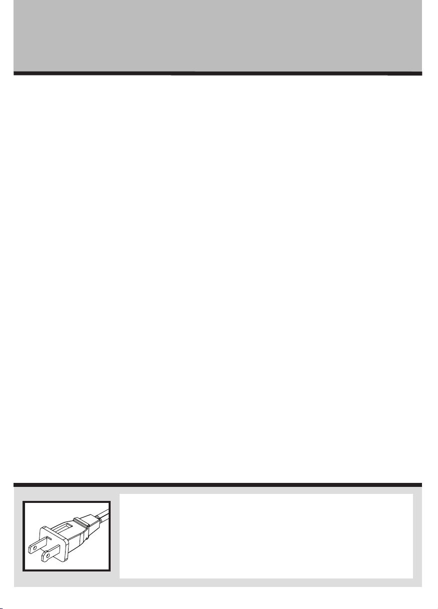
THIS APPLIANCE HAS A POLARIZED PLUG (one blade is wider than
the other). To reduce the risk of electric shock, this plug is intended to
fit in a polarized outlet only one way. If the plug does not fit fully in
the outlet, reverse the plug. If it still does not fit, contact a qualified
electrician to install the proper outlet.
DO NOT ATTEMPT TO MODIFY THIS PLUG OR DEFEAT THIS
SAFETY FEATURE IN ANY WAY.
Fig. 1
Fig. 2
Fig. 5
Alignment Post "B"
Alignment Hole "B"
Fig. 6
FCC STATEMENT
Potential for Radio/Television interference
This device complies with Part 15 of the FCC Rules.
Operation is subject to the following two conditions: (1)
This device may not cause harmful interference, and (2)
this device must accept any interference received,
including interference that may cause undesired operation.
This product has been tested and found to comply with
the limits for a Class B digital device, pursuant to part 15
of the FCC rules.
These limits are designed to provide reasonable
protection against harmful interference in a residential
installation. The product generates, uses, and can radiate
radio frequency energy and, if not installed and used in
accordance with the instructions, may cause harmful
interference to radio communications. However, there is
no guarantee that the interference will not occur in a
particular installation. If the product does cause harmful
interference to radio or television reception, which can be
determined by turning the product on or off, the user is
encouraged to try to correct the interference by one or
more of the following measures:
• Reorient or relocate the receiving antenna.
• Increase the separation between the product and the
receiver.
• Connect the product into an outlet on a circuit
different from that to which the receiver is connected.
• Consult the dealer or an experienced radio/TV
technician for help.
• Changes or modifications not expressly approved by
the party responsible for compliance could void the
user’s authority to operate the equipment.
REMOTE CONTROL
NOTE: PLEASE REMOVE THE PROTECTIVE STICKER FROM
THE REMOTE CONTROL BATTERY BEFORE OPERATION.
This unit includes one lithium battery, CR2025/3V.
Remove battery before discarding the remote.
Battery Replacement
a) Locate the battery cover from the rear side of the
remote control, and slide out the battery cover as per
the instructions marked on the cover.
b) Remove old battery.
c) Place new battery into battery compartment.
d) Slide battery compartment into the remote control
handset.
NOTES:
• Remove the battery from the equipment when it is
not being used for an extended period of time.
• Remove the used battery promptly.
• Do not discard used batteries into household trash
containers. Contact your local government for
disposal or recycling practices in your area.
Fig. 10 Remote Control
B
C
A
D
E
Fig. 9 Control Panel
A
B
E
D
C
Fig. 3
Fig. 4
Fig. 8
Fig. 7
HTF3303A_15EM1.indd 2 1/20/15 11:41 AM