SCHUMACHER® 100A 12V AUTOMATIC SMART
BATTERY SUPPORT UNIT & CHARGER
MODEL NO: BSCU170
Thank you for purchasing a Sealey product. Manufactured to a high standard, this product will, if used according to these instructions,
and properly maintained, give you years of trouble free performance.
IMPORTANT: PLEASE READ THESE INSTRUCTIONS CAREFULLY. NOTE THE SAFE OPERATIONAL REQUIREMENTS, WARNINGS & CAUTIONS. USE
THE PRODUCT CORRECTLY AND WITH CARE FOR THE PURPOSE FOR WHICH IT IS INTENDED. FAILURE TO DO SO MAY CAUSE DAMAGE AND/OR
PERSONAL INJURY AND WILL INVALIDATE THE WARRANTY. KEEP THESE INSTRUCTIONS SAFE FOR FUTURE USE.
BSCU170 Issue:2 - 31/03/23
Original Language Version
© Jack Sealey Limited
1. IMPORTANT SAFETY INSTRUCTIONS – SAVE THESE INSTRUCTIONS
This manual will show you how to use your charger safely and eectively. Please read, understand and follow these instructions and precautions
carefully, as this manual contains important safety and operating instructions. The safety messages used throughout this manual contain a signal
word, a message and an icon.
The signal word indicates the level of the hazard in a situation.
▲ DANGER
Indicates an imminently hazardous situation which, if not avoided, will result in death or serious injury to the operator or bystanders.
WARNING
Indicates a potentially hazardous situation which, if not avoided, could result in death or serious injury to the operator or bystanders.
IMPORTANT
Indicates a potentially hazardous situation which, if not avoided, could result in damage to the equipment, vehicle or property.
WARNING:
9 To reduce the risk of damage to the electric plug or cord, pull by the plug rather than the cord when disconnecting the charger.
9 An extension cord should not be used unless absolutely necessary. Use of an improper extension cord could result in a risk of re and
electric shock. If an extension cord must be used, make sure:
●The pins on the plug of the extension cord are the same number, size and shape as those of the plug on the charger.
●The extension cord is properly wired and in good electrical condition.
8 DO NOT operate the charger with a damaged cord or plug; have the cord or plug replaced immediately by a qualied service person.
8 DO NOT operate the charger if it has received a sharp blow, been dropped or otherwise damaged in any way; take it to a qualied
service person.
8 DO NOT disassemble the charger; take it to a qualied service person when service or repair is required. Incorrect reassembly may
result in a risk of re or electric shock.
2. PERSONAL PRECAUTIONS
WARNING: RISK OF EXPLOSIVE GASES
9 Remove personal metal items such as rings, bracelets, necklaces and watches when working with a lead-acid battery. A lead-acid
battery can produce a short circuit current high enough to weld a ring or the like to metal, causing a severe burn.
9 Be extra cautious, to reduce the risk of dropping a metal tool onto the battery. It might spark or short-circuit the battery or other
electrical part that may cause an explosion.
9 Use this charger for charging LEAD-ACID batteries only. It is not intended to supply power to a low voltage electrical system.
8 DO NOT use this battery charger for charging dry-cell batteries that are commonly used with home appliances. These batteries may burst
and cause injury to persons and damage to property.
8 NEVER charge a frozen battery.
9 Consider having someone nearby to come to your aid when you work near a lead-acid battery. Have plenty of fresh water and soap
nearby in case battery acid contacts your skin, clothing or eyes.
9 If battery acid contacts your skin or clothing, immediately wash the area with soap and water. If acid enters your eye, immediately ood
the eye with cold running water for at least 10 minutes and get medical attention right away. If battery acid is accidentally swallowed,
drink milk, the whites of eggs or water.
8 DO NOT induce vomiting. Seek medical attention immediately.
SAFETY SYMBOLS
BSCU170 Issue:2 - 31/03/23
Original Language Version
© Jack Sealey Limited

3. PREPARING TO CHARGE
WARNING: RISK OF CONTACT WITH BATTERY ACID. BATTERY ACID IS A HIGHLY CORROSIVE SULFURIC ACID.
3.1. Remove all cord wraps and uncoil the cables prior to using the battery charger.
3.2. If it is necessary to remove the battery from the vehicle to charge it, always remove the grounded terminal rst. Make sure all of the
accessories in the vehicle are o, to prevent arcing.
3.3. Clean the battery terminals before charging the battery. During cleaning, keep airborne corrosion from coming into contact with your
eyes, nose and mouth. Use baking soda and water to neutralize the battery acid and help eliminate airborne corrosion. DO NOT touch
your eyes, nose or mouth.
3.4. Add distilled water to each cell until the battery acid reaches the level specied by the battery manufacturer. DO NOT overll. For
a battery without removable cell caps, such as valve regulated lead acid batteries (VRLA), carefully follow the manufacturer’s
recharging instructions.
3.5. Read, understand and follow all instructions for the charger, battery, vehicle and any equipment used near the battery and charger.
Study all of the battery manufacturer’s specic precautions while charging and recommended rates of charge.
3.6 Determine the voltage of the battery by referring to the vehicle owner’s manual.
3.7. Make sure that the charger cable clips make tight connections.
4. CHARGER LOCATION
WARNING: RISK OF EXPLOSION AND CONTACT WITH BATTERY ACID.
NOTE: This is a Class A product for industrial use only, for use with professional equipment with a total rated power greater than
1 kW. In a domestic environment, this product may cause radio interference, in which case the user may be required to take adequate
measures.
4.1. Locate the charger as far away from the battery as the DC cables permit.
4.2. NEVER place the charger directly above the battery being charged; gases from the battery will corrode and damage the charger.
8 DO NOT set the battery on top of the charger.
4.3. NEVER allow battery acid to drip onto the charger when reading the electrolyte specic gravity or lling the battery.
5. FOLLOW THESE STEPS WHEN BATTERY IS INSTALLED IN VEHICLE
WARNING: A SPARK NEAR THE BATTERY MAY CAUSE A BATTERY EXPLOSION.
TO REDUCE THE RISK OF A SPARK NEAR THE BATTERY :
5.1. Position the AC and DC cables to reduce the risk of damage by the bonnet, door and moving or hot engine parts. NOTE: If it is
necessary to close the bonnet during the charging process, ensure that the bonnet does not touch the metal part of the battery clips or
cut the insulation of the cables.
5.2. Stay clear of fan blades, belts, pulleys and other parts that can cause injury.
5.3. Check the polarity of the battery posts. The POSITIVE (POS, P, +) battery post usually has a larger diameter than the NEGATIVE
(NEG, N, -) post.
5.4. Determine which post of the battery is grounded (connected) to the chassis.
5.5. For a negative-grounded vehicle, connect the POSITIVE (RED) clip from the battery charger to the POSITIVE (POS, P, +) ungrounded
post of the battery. Connect the NEGATIVE (BLACK) clip to the vehicle chassis or engine block away from the battery. DO NOT
connect the clip to the carburettor, fuel lines or sheet-metal body parts. Connect to a heavy gauge metal part of the frame or engine
block.
5.6. For a positive-grounded vehicle, connect the NEGATIVE (BLACK) clip from the battery charger to the NEGATIVE (NEG, N, -)
ungrounded post of the battery. Connect the POSITIVE (RED) clip to the vehicle chassis or engine block away from the battery.
DO NOT connect the clip to the carburettor, fuel lines or sheet-metal body parts. Connect to a heavy gauge metal part of the frame or
engine block.
5.7. Connect charger AC supply cord to electrical outlet and press to turn the output on.
5.8. When disconnecting the charger, press to turn the output o, disconnect the AC cord, remove the clip from the vehicle chassis and
then remove the clip from the battery terminal.
6. FOLLOW THESE STEPS WHEN BATTERY IS OUTSIDE VEHICLE
WARNING: A SPARK NEAR THE BATTERY MAY CAUSE A BATTERY EXPLOSION.
TO REDUCE THE RISK OF A SPARK NEAR THE BATTERY :
6.1. Check the polarity of the battery posts. The POSITIVE (POS, P, +) battery post usually has a larger diameter than the NEGATIVE
(NEG, N, -) post.
6.2. Attach at least a 24-inch long 4 gauge (AWG) insulated battery cable to the NEGATIVE (NEG, N, -) battery post.
6.3. Connect the POSITIVE (RED) charger clip to the POSITIVE (POS, P, +) post of the battery.
6.4. Position yourself and the free end of the cable you previously attached to the NEGATIVE (NEG, N, -) battery post as far away from the
battery as possible – then connect the NEGATIVE (BLACK) charger clip to the free end of the cable.
8 DO NOT face the battery when making the nal connection.
6.5. Connect charger AC supply cord to electrical outlet and press to turn the output on.
6.6. When disconnecting the charger, press to turn the output o, disconnect the AC cord, remove the clip from the cable attached to the
negative battery terminal and then remove the clip from the positive battery terminal.
6.7. A marine (boat) battery must be removed and charged on shore. To charge it onboard requires equipment specially designed for
marine use.
BSCU170 Issue:2 - 31/03/23
Original Language Version
© Jack Sealey Limited
7. GROUNDING AND AC POWER CORD CONNECTIONS
WARNING: RISK OF ELECTRIC SHOCK OR FIRE
7.1. This battery charger is for use on a nominal 220-240V, 50/60Hz circuit. (See the warning label on the charger for the correct input
voltage.) The plug must be plugged into an outlet that is properly installed and grounded in accordance with all local codes and
ordinances. The plug pins must t the receptacle (outlet). DO NOT use with an ungrounded system.
▲ DANGER:
7.2. NEVER alter the AC cord or plug provided – if it does not t the outlet, have a proper grounded outlet installed by a qualied
electrician. An improper connection can result in a risk of an electric shock or electrocution.
7.3. Recommended minimum AWG size for extension cord:100 feet (30.5 meters) long or less – use a 12 gauge (3.31 mm²) extension
cord. Over 100 feet (30.5 meters) long – use an 8 gauge (8.36 mm²) extension cord.
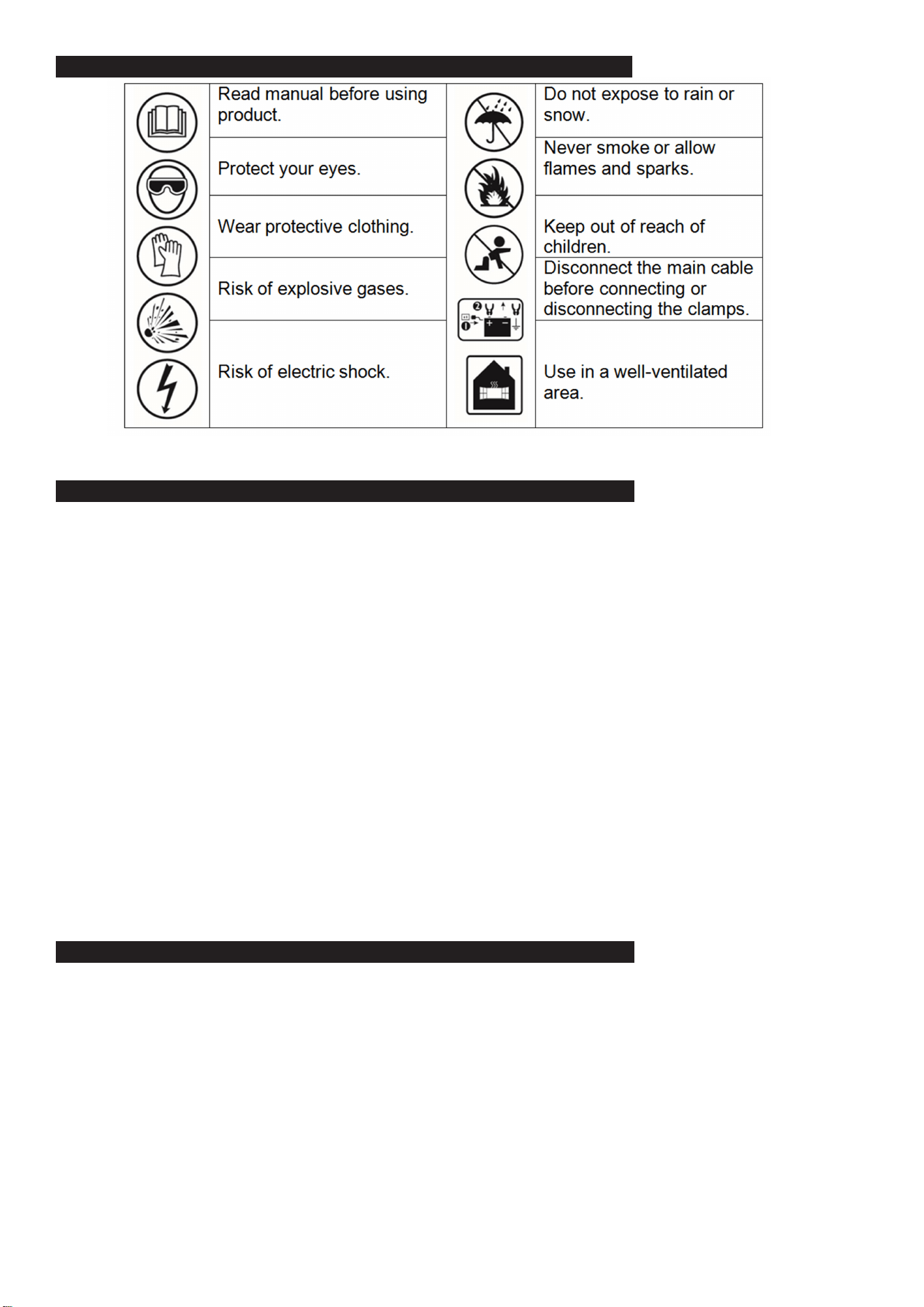
8. MOUNTING INSTRUCTIONS
NOTE: The BSCU170 is non-portable equipment.
Suitable for mounting only on concrete or other non-combustible surfaces.
To permanently mount the charger, use the following instructions:
8.1. Slide all 4 brackets (Item 1) into the track on the back, from the right side, as shown above. Make sure the set screws (Item 2) are
unscrewed enough so they do not scratch the surface of the housing.
8.2. Measure what you are mounting the charger to before deciding where to locate the brackets (add an additional ¼ to ½ inch). Use
the ruler on the label (Item 3) to mount the brackets (Item 1) in the correct position (position each bracket an equal distance from the
centre of the charger). Note that the inches shown are for both bracket dimensions combined (meaning the dimensions are doubled),
this is for easier reference. Make sure the ¼-28 set screws (Item 4) are unscrewed enough so the pointed end is almost ush with the
bracket. Mount the brackets (Item 1) by tightening all 8 set screws (Item 2) to 14 in/lb (1.6 n/m) of torque.
8.3. Lift the charger by its handle and set it against your mounting location, tighten the set screws (Item 4) to 66 in/lb (7.5 n/m) of torque to
secure the brackets (Item 1), starting with the top two brackets rst.
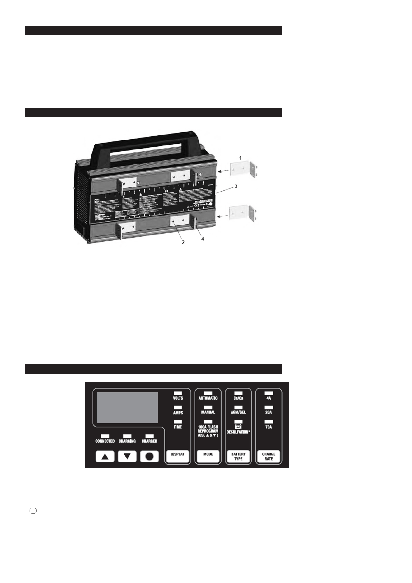
9. CONTROL PANEL
●CONNECTED (yellow/orange) LED. The CONNECTED LED will light when the battery is properly connected.
●CHARGING (yellow/orange) LED. When charging begins, the CHARGING LED will light.
●CHARGED (green) LED. The CHARGED LED will light when the charger has gone into maintain mode.
●▲and▼ (UP and DOWN) Buttons. Use these buttons to select the amount of time or voltage, depending on the display function selected.
●
●
(Start/Stop) Button. This is the start and stop button for all modes.
●Digital Display. The Digital Display gives a digital indication of voltage, amperes or time, depending on the display function chosen.
●Display Button. Use this button to set the function of the digital display to one of the following:
●VOLTS (Voltmeter). The voltmeter indicates the voltage at the battery terminals. If the reading is 12.8 volts or more, the battery is charged.
●AMPS (Ammeter). The ammeter indicates the amount of current, measured in amps, that is being drawn by the battery (± 2 amps).
NOTE: The 70 amp charge rate cycles between 20 amps and 70 amps during the charging process and the ammeter will show this. This is a
normal condition.
BSCU170 Issue:2 - 31/03/23
Original Language Version
© Jack Sealey Limited

●TIME (Timer – Range: 10 minutes to 120 minutes) Used only in manual mode, the main function of the timer is to prevent overcharging while
allowing a battery time to obtain a satisfactory charge.
To properly set the timer, you must know the size of the battery in ampere hours or reserve capacity in minutes and the state of charge.
●Hold: This position defeats the timer function, allowing for continuous operation. Use when you want to charge more than 2 hours.
Be sure to monitor the charging procedure and stop when the battery is charged. Not doing so may cause damage to your battery or
may cause other personal property damage or personal injury.
●Mode Button:
Use this button to select between the AUTOMATIC CHARGE, MANUAL CHARGE and FLASH REPROGRAM function.
See Operating Instructions for details of these functions.
●Battery Type/Desulfation Mode Button:
Set the type of battery to be charged, or Desulfation Mode.
●Ca/Ca (Calcium) – Calcium batteries are acid batteries impregnated with calcium.
●AGM/GEL (Absorbed Glass Mat/Gel Cell) – AGM batteries have electrolyte absorbed in separators consisting of a sponge-like mass of matted
glass fibre. Gel batteries contain gelled electrolytes. These batteries are sealed with valves and should not be opened.
● Desulfation Mode – If the battery is left discharged for an extended period of time, it could become sulfated and not accept
normal charge. If you select , the charger will switch to a special mode of operation designed for sulfated batteries.
NOTE: When charging a battery that is not marked, check the manual of the item which uses the battery for the correct battery type. Make sure
the battery complies with the safety instructions in Section 2.3.
●Charge Rate Button Use this button to set the maximum charge rate to one of the following:
●4A Charge Rate – For charging small batteries, such as those commonly used in garden tractors, snowmobiles and motorcycles.
●20A and 70A Charge Rate – For charging automotive and marine batteries.
NOTE: Charge rate cannot be selected while using Desulfation Mode.
10. OPERATING INSTRUCTIONS
BATTERY INFORMATION
This charger can be used with 12V batteries with rated capacities of 12 Ah to 111 Ah.
CHARGER OPERATION
NOTE: Once automatic charging or ash reprogramming has started, the buttons will not work until you turn o the output, with the
exception of (In MANUAL mode, ▲ and ▼also still operate normally.) When the display shows “OFF”, no buttons will work for ve
seconds as the charger automatically goes back to the default settings.
Automatic Charging
1. Connect the battery and AC power, following the precautions listed in sections 5, 6 and 7.
2. Set the BATTERY TYPE to Ca/Ca, AGM/GEL or Desulfation.
3. Set the MODE to AUTOMATIC CHARGE.
4. Set the CHARGE RATE to 4A, 20A or 70A. NOTE: Charge rate cannot be selected while using Desulfation Mode.
5. Press when you are ready to start charging.
6. The CHARGING (yellow/orange) LED will light.
NOTE: Automatic charging starts only if the CONNECTED LED is lit and the battery has at least a 1V charge. If the battery is less than
1V, press and hold for ve seconds to start Automatic Charging, or charge it in Manual mode for ve minutes then switch back to
Automatic Charge.
7. The CHARGED (green) LED will light when charging is complete and the charger has gone into maintain mode.
Manual Charging
1. Connect the battery and AC power following the precautions listed in sections 5, 6 and 7.
2. Set the BATTERY TYPE to Ca/Ca, AGM/GEL or Desulfation.
3. Set the MODE to MANUAL CHARGE. (The TIME LED will start blinking.)
4. Use▲and▼ to set the time (shown in minutes) you want the charger to charge the battery. Set to “HLd” to run the charger without a
time limit.
5. Set the CHARGE RATE to 4A, 20A or 70A. NOTE: Charge rate cannot be selected while using Desulfation Mode.
6. Press when you are ready to start charging.
NOTE: Be sure to monitor the charging procedure and stop when the battery is charged. Failure to do so may cause damage to your battery
or may cause other personal property damage or personal injury.
Charging
If the charger does not detect a properly connected battery, the CONNECTED (yellow/orange) LED will not light until such a battery is
detected. Charging will not begin while the CONNECTED LED is not on. When charging begins, the CHARGING (yellow/orange) LED
will light.
Battery Percent and Charge Time
This charger adjusts the charging time in order to charge the battery completely, eciently and safely. The microprocessor
automatically performs the necessary functions.
Charge Rate – The charge rate is measured in amps. This charger provides charge rates of 4A, 20A and 70A. The 4A rate is for charging
smaller batteries, such as those used for motorcycles and garden tractors. Such batteries should not be charged using the 20A or 70A
rate. The 20A and 70A rates are for charging larger batteries. In the 20A and 70A mode, the charger begins at a low-charge rate and
increases the charge rate if it is determined that the battery can accept the higher rate. All charging modes will decrease the charge
current as the battery approaches maximum charge.
Automatic Charging Mode-When an automatic charge is performed, the charger switches to the maintain mode automatically after the battery
is charged. For a battery with a starting voltage under 1 volt, press and hold for ve seconds to start Automatic Charging, or use
manual mode to pre-charge the battery for ve minutes to get additional voltage into the battery for the charger to analyze.
Aborted Charge -If charging cannot be completed normally, charging will abort. When charging aborts, the charger’s output is shut o, the
CHARGING (yellow/orange) LED will go out and the digital display will show « bAd bAt ». The charger ignores all buttons except
●
in that state. Press
●
to reset after an aborted charge.
●
●
●
●
BSCU170 Issue:2 - 31/03/23
Original Language Version
© Jack Sealey Limited
Desulfation Mode
If the battery is left discharged for an extended period of time, it could become sulfated and not accept normal charge. If you select
, the charger will switch to a special mode of operation designed for sulfated batteries. For the best performance, AUTOMATIC
CHARGE Mode is recommended for Desulfation Mode. If successful, the charger will fully desulfate and charge the battery, and then
the green LED will light. Desulfation could take up to 10 hours in AUTOMATIC CHARGE mode. If desulfation fails, charging will abort
and the charger will go into Abort Mode. If MANUAL CHARGE mode is selected and the timer is set to between 10-120 minutes,
desulfation will stop at the specied time. If the timer is set to HOLD, the maximum time for desulfation will be 10 hours.
Completion of Charge
Charge completion is indicated by the CHARGED (green) LED. When lit, the charger has stopped charging and switched to the
Maintain Mode of operation. If you are charging a deep cycle battery, the CHARGED LED comes on when the battery is charged
enough for normal use.
Maintain Mode
When the CHARGED (green) LED is lit, the charger has started Maintain Mode. In this mode, the charger keeps the battery fully
charged by delivering a small current when necessary. The voltage is maintained at 13.2V.
100A Flash Reprogramming
NOTE: DO NOT attempt to Flash Reprogram a vehicle that has a discharged or defective battery. Make sure that the vehicle battery
is in good condition and fully charged before proceeding. In Flash Reprogramming Mode, the charger is able to deliver 70A charging
current continuously, and to deliver up to 100A for three minutes.
1. Set MODE to FLASH REPROGRAM. (The VOLTS LED will start blinking.)
2. Use▲ and ▼ to adjust voltage to the voltage needed for the vehicle being programmed (refer to OEM specications). Voltage selected
is shown on the digital display. The unit has a voltage range of 13 to 14.8, with a default of 14.2.
NOTE: When the VOLTS LED stops blinking, the display shows the selected voltage.
3. Press to turn on the output.
4. When nished with Flash Reprogramming, press to exit this mode.
Using the Battery Voltage Tester
Overview
This battery charger has a built-in voltmeter to measure your battery’s voltage. The charger does not have a built in load tester. As
such, a recently charged battery could have a temporarily high voltage due to what is known as “surface charge”. The voltage of such
a battery will gradually drop during the period immediately after the charging system is disengaged. Consequently, the tester could
display inconsistent values for such a battery. For a more accurate reading, the surface charge should be removed by temporarily
creating a load on the battery, such as by turning on lights or other accessories for a couple of minutes before you read the display.
Read it a couple of minutes after you have turned the headlights o.
Testing Sequence: There are seven basic steps required to test the battery state of charge:
NOTE: You cannot test the battery voltage while charging.
1. With the charger unplugged from the AC outlet, connect the charger to the battery following the instructions given in Sections 6 and 7.
2. Plug the charger AC power cord into the AC outlet.
3. The CONNECTED (yellow) LED will light if a properly connected battery is detected.
4. Conrm the CHARGING (yellow) LED is o.
5. Set the DISPLAY to VOLTS.
6. If the output is on, press
●
. If the output is already o, do not press .
7. Read the voltage on the digital display.
General Charging Notes
Fans: The charger is designed to control its cooling fans for ecient operation. Consequentially, it is normal for the fans to start and
stop when maintaining a fully charged battery. Keep the area near the charger clear of obstructions to allow the fans to operate
eciently. NOTE: The charger has thermal protection, and it will shut down if it gets too hot.
Voltage: The voltage displayed during charging is the charging voltage and is usually higher than the battery’s resting voltage.
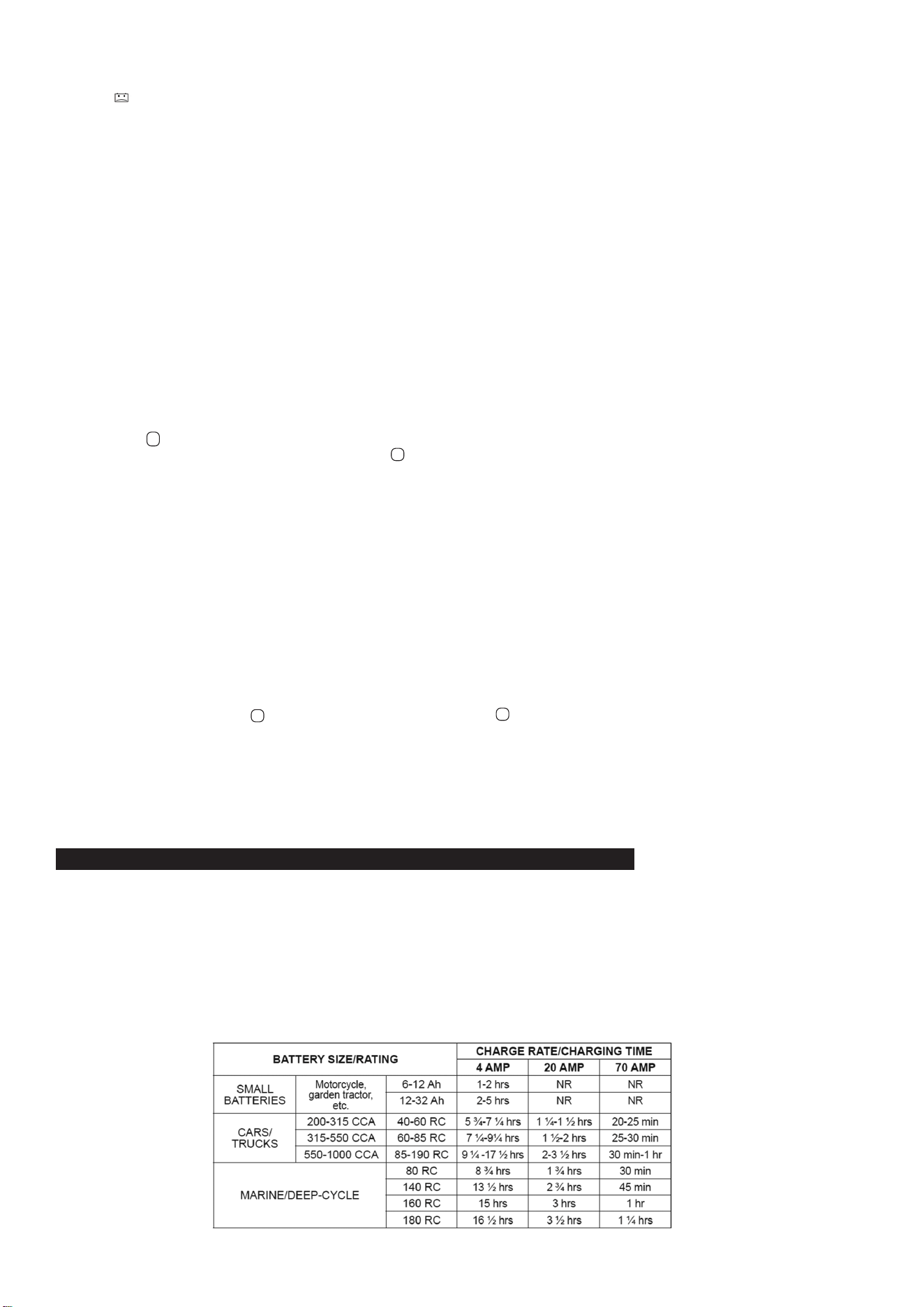
11. CALCULATING CHARGE TIME
11.1. Use the following table to more accurately determine the time it will take to bring a battery to full charge. First, identify where your
battery ts into the chart.
11.2. NR means that the charger setting is NOT RECOMMENDED.
11.3. Find your battery’s rating on the following chart and note the charge time given for each charger setting. The times given are for
batteries with a 50 percent charge prior to recharging. Add more time for severely discharged batteries.
●
●
●
BSCU170 Issue:2 - 31/03/23
Original Language Version
© Jack Sealey Limited

12. MAINTENANCE INSTRUCTIONS
12.1. Before performing maintenance, unplug and disconnect the battery charger (see sections 5.8 and 6.7).
12.2. After use, unplug the charger and use a dry cloth to wipe all battery corrosion and other dirt or oil from the terminals, cords, and the
charger case.
12.3. After every 100 hours or whenever you see dust accumulating on the fan blades, you should clean both fans using compressed air
(as shown).
NOTE: Use the compressed air on the fan blades only. Do not blow dirt into the fan shaft or bearing. These fans push
a lot of air and are precision balanced. Excessive dirt and grime build up will cause the fan to be unbalanced
and wear out quickly. If the fans fail, the charger may overheat and the thermal protection of the charger will
shut it down.
12.4. Ensure that all of the charger components are in place and in good working condition, including the plastic
boots on the battery clips.
12.5. Servicing does not require opening the unit, as there are no user-serviceable parts.
13. MOVING AND STORAGE INSTRUCTIONS
13.1. If the charger is moved around the shop or transported to another location, take care to avoid/prevent damage to the cords, clips and
charger. Failure to do so could result in personal injury or property damage. DO NOT store the clips on the handle, clipped together, on
or around metal, or clipped to cables.
13.2. Store the charger unplugged. The cord will still conduct electricity until it is unplugged from the outlet.
14. SPECIFICATIONS
Input..............................................................................................220-240V~ 50/60Hz 10A
Output:
Charging mode..................................................................................12V 4A / 20A / 70A
Desulfation mode...............................................................................................15.8V max.
Reprogram mode.............................................13-14.8V 0-70A, 100A for three minutes
Weight......................................................................................................................9.56kg
Operating temperature.....................................................-20 °C – +40 °C (-4 °F–+104 °F)
Operating humidity.................................................................0 – 90% RH non-condensing
Working life (MTBF)........................................................................................85,000 hours
BSCU170 Issue:2 - 31/03/23
Original Language Version
© Jack Sealey Limited
BSCU170 Issue:2 - 31/03/23
Original Language Version
© Jack Sealey Limited
Sealey Group, Kempson Way, Suffolk Business Park, Bury St Edmunds, Suffolk. IP32 7AR
01284 757500 sales@sealey.co.uk www.sealey.co.uk
ENVIRONMENT PROTECTION
Recycle unwanted materials instead of disposing of them as waste. All tools, accessories and packaging should be sorted,
taken to a recycling centre and disposed of in a manner which is compatible with the environment. When the product
becomes completely unserviceable and requires disposal, drain any fluids (if applicable) into approved containers and
dispose of the product and fluids according to local regulations.
WEEE REGULATIONS
Dispose of this product at the end of its working life in compliance with the EU Directive on Waste Electrical and Electronic Equipment
(WEEE). When the product is no longer required, it must be disposed of in an environmentally protective way. Contact your local solid
waste authority for recycling information.
Note: It is our policy to continually improve products and as such we reserve the right to alter data, specifications and component parts without prior
notice. Please note that other versions of this product are available. If you require documentation for alternative versions, please email or call
our technical team on technical@sealey.co.uk or 01284 757505.
Important: No Liability is accepted for incorrect use of this product.
Warranty: Guarantee is 12 months from purchase date, proof of which is required for any claim.
REGISTER YOUR
PURCHASE HERE