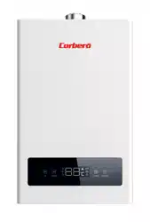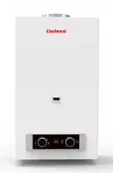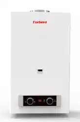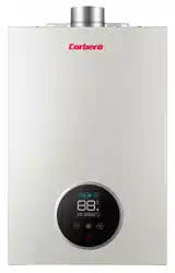
CALENTADORDEAGUAESTANCOBAJO
NO
x
Capacidad11y14l.
M
anual
deinstalacióny
uso
Modelo:
CCVEST11NOXGB
CCVEST14NOXGB
CCVEST11NOXGN
CCVEST14NOXGN
Antesdeutilizarelaparato,leadetenidamenteestemanualyconsérveloparafuturas
referencias.
Lascaracterísticasyespecificacionesdeestosmodelosestánsujetosacambiosinprevio
aviso.

2
ISO9001 Certificado
Gracias por comprar nuestro calentador de agua a gas.
Contenidos
●Consejo especial…………………………………………………………………………………………………………..3
●Características y beneficios.…………………………………………………………………………………………3
●Especificaciones.………………………………………………………………………………………………………….5
●Componentes………...………………………………………………………………………………………………….6
●Instalación.…………………………………………………………………………………………………………………8
●Utilizando métodos………………………………………………………………………………………………….14
●Precauciones de seguridad…………………………………………………………………………..……………18
●Mantenimiento……………………………………………………………………………………………..……………21
●Guía de resolución de problemas…………………………………………………………………..……………22
●Explicación de los códigos de error………………………………………………………………..…………..23
●Diagrama eléctrico…………………………………………………………………………………………………..…24
●Instrucciones de transformación……………………………………………………………………….……..…25

3
Consejo Especial
Lea las instrucciones técnicas antes de instalar el aparato.
Lea las instrucciones del usuario antes de encender el aparato.
El fabricante o cualquier peligro derivado de la instalación y las operaciones no son responsables de
cualquier peligro resultante de la instalación y las operaciones que no se ajusten a este manual.
Cuando la temperatura exterior es inferior a 0, el agua residual dentro del calentador debe ser vaciado
después de su uso.
EN26 : 2015
Características y beneficios
▪ Sistema de control inteligente de microordenador
El componente central del calentador de agua a gas es el sistema de control inteligente microordenador,
que es una de las tecnologías mecatrónicas más avanzadas de la actualidad. El chipset de la CPU puede
analizar automáticamente y establecer rápidamente el parámetro de trabajo óptimo de acuerdo con
diferentes datos, como la cantidad de agua que fluye, la situación de presión y la temperatura real del
agua de entrada.
▪ Control digital para la temperatura constante automática del agua de salida
Esta función es controlar la temperatura del agua de salida mediante un sensor de temperatura y
transferir la información al microordenador, de modo que el microordenador pueda ajustar la cantidad
de suministro de aire y gas para garantizar la temperatura constante del agua de salida según la
temperatura establecida. por el usuario y la temperatura real del agua de entrada automáticamente.
▪ Presión de agua de arranque baja
La presión de agua de arranque más baja de este producto podría alcanzar los 0.02 MPa (la tasa de agua
mínima es de 2.5 L / min), por lo que también se podría usar en el área de residencia con baja presión
de agua.
▪ Función de memoria inteligente artificial
El calentador de agua a gas podría funcionar con la temperatura que configuró la última vez cuando lo
reinició, de modo que no necesita volver a ajustar la temperatura, lo que es una gran experiencia de la
idea de la ergonomía.
▪ Efectivo y ahorro de energía
Este producto cuenta con tecnologías avanzadas llamadas Combustión reforzada y Combustión forzada.
Estas patentes pretenden hacer el mejor uso de la energía térmica con alta eficiencia de trabajo.

4
• Ajustar la temperatura al tacto
Puede ajustar fácilmente la temperatura requerida tocando la pantalla digital. La temperatura de ajuste
es de 35º a 65º, que puede cumplir diferentes requisitos de temperatura del agua con una operación
fácil.
• Protección de seguridad múltiple
Este producto tiene protecciones de seguridad que incluyen protección con autocomprobación,
protección contra el fuego, protección contra sobrecalentamiento, protección accidental contra cortes
de energía, protección contra averías del calentador, protección contra sobrecarga eléctrica, protección
contra fugas eléctricas, protección contra la presión del viento, protección contra sobrecalentamiento,
sincronización protección, etc.
• Conexión al Sistema Solar
La placa de circuito del calentador de agua viene de salida activada con la función que puede ser en serie
con el sistema de agua solar, el calentador de agua tiene las siguientes condiciones: cuando la
temperatura de ajuste sea 5º C menor que la temperatura de entrada del agua, el calentador de agua
dejará de funcionar mostrando el código de EE con el sonido de zumbido diez veces. Cuando la
temperatura de ajuste es al menos 5º C más que la temperatura de entrada del agua, el calentador de
agua puede arrancar automáticamente y funcionar normalmente. Cuando se instala en serie con un
calentador de agua solar, se debe instalar una válvula mezcladora de agua en el punto de toma para
evitar que hierva el agua.
• Consejos
La conclusión anterior proviene de la prueba de protección de seguridad en condiciones experimentales
de laboratorio. Puede ser afectado por el entorno real de uso. Por lo tanto, utilice el producto en
condiciones adecuadas en lugar de usarlo de forma devastadora.

5
Especificaciones
Modelo
CCVEST11NOXGN CCVEST11NOXGB CCVEST14NOXGN CCVEST14NOXGB
Entrada de calor nominal
22 kW
22 kW
28 kW 28 kW
Salida de calor nominal
19,2 kW
19,2 kW 25,4 kW
25,4 kW
Entrada de calor mínima
8 kW
8 kW
9 kW
9 kW
Salida de calor mínima 7,4 kW 7,4 kW
8,2 kW 8,3kW
Caudal máximo (25º C) 11 kg/min 11 kg/min 14 kg/min 14 kg/min
Tipo de aparato C13, C33
Tipo de gas 2H-G20mbar 3B/P-G30-29mbar 2H-G20m bar 3B/P-G30-
29mbar
Categoría gas I2@20mbar I3B/P-30-29mbar I2@20mbar I3B/P-30-
29mbar
Contraseña de homologación 0063CR7772
Presión de agua máxima
Pw~10 bar
Presión de agua mínima
Pw~0,2 bar
Suministro de energía eléctrica 220
-240VA,50Hz
Energía eléctrica 29W 29W 38W 38W
Grado de protección eléctrica
IPX4
Método de ignición Encendido automático
Entrada gas
G1/2
Tubería
Entrada agua fría
G1/2
Salida agua caliente
G1/2
Diámetro conducto humos Ø100 exterior, Ø60 interior
Ad
ver
t
e
n
c
ia:
Lea las instrucciones técnicas antes de instalar el aparato.
0063/
20

6
Componentes
Conector del conducto de
humos
Cubierta
Enchufe
Display & Panel control
Salida agua caliente
Entrada Gas Válvula seguridad
Entrada agua fría

A
B
Modelo
AB
150165
170185
CCVEST11NOx
CCVEST14NOx
(La información de la dimensión es sólo para referencia. Por favor, consulte el producto real)
7

8
F
Instalación
Póngase en contacto con su distribuidor local de gas o con el departamento de gestión de gas para que
un ingeniero calificado instale el calentador de agua a gas (se recomienda que los usuarios no lo instalen
por sí mismos).
Se debe llamar al instalador para que instale y ajuste el dispositivo, según corresponda.
Se prohíbe que este producto use este calentador de agua a gas cuando la tubería de humos no se haya
instalado correctamente de acuerdo con las instrucciones.
■ Requerimientos de instalación
● El conducto del calentador de agua a gas debe instalarse a través de una pared externa, el
calentador no puede ser instalado en el exterior. (Fig.3)
INTERIOR
EXTERIOR
HUMO COMÚN
Fig.3 Fig.4
Fig.5 Fig.6

9
● El calentador de agua a gas instalado en una habitación adecuadamente ventilada, de acuerdo con las
regulaciones vigentes. No está permitido instalar en el dormitorio, el subsuelo, el baño o cualquier otro lugar con
mala ventilación. (Para B23, tipo B53)
● La chimenea del calentador no se puede conectar a una chimenea común (Fig. 4).
● No instale el calentador en lugares donde se utilicen productos químicos especiales, como lavanderías o
fábricas, etc. De lo contrario, podría oxidarse, acortar la vida útil del calentador o impedir el funcionamiento
normal. (Fig. 5)
● No instale el calentador sobre las estufas de gas u otras fuentes de calor. (Fig. 6)
● El calentador de agua a gas debe mantenerse alejado de los materiales combustibles con la distancia
mostrada al menos en la Fig. 7.
● Cuando los materiales de las piezas de instalación son combustibles o inflamables, se debe utilizar un tablero
resistente al marco para aislarlos, la placa resistente al calor y la separación de la pared deben ser supe riores a
10 mm, y el tamaño de la placa térmica debe ser mayor que la carcasa del calentador de agua de 10 mm. (Fig. 8)
Materiales combustibles
Combustible pared
Tablero a prueba de cuadros
Fig. 7 Fig. 8
● Los cables eléctricos y el equipo eléctrico no pueden colocarse en la parte superior del calentador de agua a
gas. La distancia horizontal entre el calentador de agua a gas y otros equipos eléctricos debe ser de más de 400
mm.
● La toma de corriente debe tener un cable a tierra confiable para mejorar la seguridad. Para reducir el número
de veces de enchufes, es mejor usar un zócalo con un interruptor. Cuando el calentador de agua termine de
funcionar, apáguelo para evitar electrificación a largo plazo. La toma de alimentación no debe instalarse en un
entorno húmedo.
● El zócalo debe instalarse en el lateral del producto y nunca debe instalarse debajo de la máquina o en lugares
donde haya salpicaduras, cerca de la fuente de calor, en exposición al sol y la lluvia, o en lugares donde no sea
fácil de controlar.
● El lugar de instalación del zócalo debe estar lejos del espacio de pulverización, para evitar rociar el zócalo
durante la ducha.

10
▪ Método de instalación.
1. Instalación de calentador de agua a
g
as.
Perfore agujeros en la pared de acuerdo con la Fig. 9, coloque un perno de expansión en el orificio
superior y una junta de plástico en el orificio inferior, monte el calentador de agua verticalmente en el
perno superior sin inclinación y apriete los orificios inferiores con pernos de expansi
ó
n.
.
Fig. 9 (Unit: mm)
2.
Instalación de tuberías de agua y gas (fig. 10).
Se p u e d e u t i l i z a r cuando el sistema de combustión puede garantizar que la presión de gas
proporcionada pueda alcanzar el requisito más bajo. Si el calentador de agua a gas alcanza la entrada de
calor nominal, la presión del gas debe alcanzar la entrada de calor nominal en la forma de parámetro
tecnológico.
Salida
agua
caliente
Entrada
Gas
Entrada
agua fría
Fig.10

11
● Entrada de gas
(1) Antes de conectar el suministro de gas, verifique la placa de características en el lado derecho de la cubierta
frontal derecha para asegurarse de que el calentador esté clasificado para el mismo gas al que se conectará.
(2) Todas estas tuberías deben ser nuevas o usadas previamente para ningún otro propósito que no sea el
transporte de gas; y debe estar en buen estado y libre de obstrucciones internas. Los extremos entallados se
escariarán hasta el diámetro total de la tubería. Todos los accesorios utilizados deben ser de hierro maleable,
latón amarillo o accesorios de plástico aprobados. Y el tubo flexible no está permitido.
(3) Cuando se realicen las conexiones, compruebe si hay fugas de gas en todas las juntas (esto incluye todas las
tuberías existentes). Aplique agua jabonosa a todos los accesorios de gas y la válvula de gas. Las burbujas de
jabón son un signo de una fuga.
NOTA: No se puede introducir ninguna otra sustancia que no sea aire, dióxido de carbono o nitrógeno en la
tubería de gas.
NOTA: Si tiene una fuga, apague el gas. Después de verificar la fuga, apriete los accesorios apropiados para
detener la fuga. Encienda el gas y verifique nuevamente con una solución jabonosa. Nunca realice pruebas de
fugas de gas con un fósforo o una llama.
● Entrada de agua fría
(1) Cuando esté frente al calentador, la entrada de agua fría está a su derecha y la salida de agua caliente está a
su izquierda. Si bien las tuberías de agua en toda su estructura pueden ser distintas del cobre, recomendamos que
las tuberías de cobre se utilicen al menos 0,92 m antes y después del calentador (siga los códigos locales).
Mantenga la tubería de entrada de agua a no menos de 1/2” de diámetro para permitir la capacidad de flujo total.
(2) Recuerde que la presión del agua debe ser suficiente para activar el calentador al extraer agua caliente del
piso superior. Si las conexiones de calor y frío al calentador se invierten, el calentador no funcionará. Los
accesorios de cobre o cobre de 1/2” funcionan mejor cuando se conectan a los conectores. Los conectores de tipo
flexible facilitarán la instilación y se sellarán a la válvula de agua mediante una conexión de unión con una junta
de tipo arandela en la junta. En esta junta no se debe usar cinta adhesiva ni cinta de rosca. Asegúrese de que no
haya partículas sueltas o suciedad en la tubería. (Fig. 10)
(3) La presión del agua debe ser suficiente para activar el calentador de agua, la presión máxima para el aparato
es de 10 bar, incluso con los efectos de la dilatación del agua, la presión del agua en el aparato no debe exceder
este valor.
● Salida de agua caliente.
Use un tubo flexible o rígido para conectar con el pulverizador sin válvula. Si se conecta una válvula o un
interruptor al rociador, la tubería de salida no debe usar calor y presión de materiales insondables, como plásticos,
tuberías de aluminio, para evitar que la tubería se rompa y escalde al usuario.

12
3. Instalación de la chimenea:
● Instalación en conducto de humos del calentador de agua a gas de escape forzado (tipo B23, B53)
Este producto es de gas de escape forzado tipo calentador de agua; Puede usarse solo después de que el
conducto de humos se instale de acuerdo con los requisitos estrictos y pueda expulsar el gas residual al área
exterior. No se permite usar el calentador de agua a gas sin instalar el conducto de humos correctamente.
Por favor, siga los requisitos a continuación durante la instalación del conducto de humos:
(1) Utilice la chimenea suministrada por nuestra empresa, refiriéndose a la Fig. 11 sobre el método de
instalación. Si el conducto de humos es demasiado corto, puede extenderlo adecuadamente. Revise el
conducto de humos y vea si hay algún daño o fuga cada medio año.
(2) La longitud del conducto de humos debe ser inferior a 8 m.
(3) La distancia horizontal del conducto de humos es la más corta, mejor. El extremo del conducto de humos
debe tener una inclinación de 20 hacia abajo (Fig. 11), para permitir que el agua de condensación salga.
(4) La d i s t a n c i a e n t r e el conducto de humos y los materiales combustibles debe ser mayor que 150mm.
Si el conducto de humos necesita atravesar los materiales combustibles o la pared, debe usar el material de la
pantalla térmica para empacar el conducto de humos con un espesor superior a 20 mm. Refiérase a la Fig. 7)
(5) No hay cemento entre el conducto de humos y la pared para la comodidad de mantenimiento. (6) El
conducto de humos debe fijarse firmemente. La parte de conexión podría usar una lámina autoadhesiva para
evitar que el gas residual vuelva a entrar en la habitación.
Orificio entrada aire
(B23, B53 type) (C13 type) (C33 type)
Fig. 11
● Instalación en el conducto de humos del calentador de agua a gas del tipo de escape forzado y
suministro de aire (tipo C13, C33)
Este producto es un calentador de agua a gas de escape forzado y de suministro de aire, que se puede
usar antes de agotar el gas residual hacia el exterior de acuerdo con los requisitos más estrictos. No se
permite usar el calentador de agua a gas sin operar la chimenea correctamente.

13
Por favor, siga los requisitos a continuación durante la instalación del conducto de humos:
(1) Utilice la chimenea suministrada por nuestra empresa, refiriéndose a la Fig. 11 sobre el
método de instalación. Si el conducto de humos es demasiado corto, puede extenderlo
adecuadamente. Revise el conducto de humos y vea si hay algún daño o fuga cada medio año.
Instale la chimenea después de que el cuerpo del calentador esté fijo. Primero, coloque el
conducto fijo a través del orificio en la pared, luego inserte el codo en la salida de escape del
calentador de manera suave, el extremo del tiro debe tener una inclinación hacia abajo de 2 °
(Fig. 11), de lo contrario, la corriente puede fluir hacia el calentador y dañarlo.
(2) La longitud del conducto de humos debe ser inferior a 4 m, y el número de codos no debe
ser superior a 4 (un codo equivalente a 1 m de tubo recto).
(3) La distancia entre el conducto de humos y los materiales combustibles debe ser mayor que
150 mm. Si el conducto de humos necesita atravesar los materiales combustibles o la pared,
debe usar el material de la pantalla térmica para empacar el conducto de humos con un espesor
superior a 20 mm. (Refiérase a la Fig. 7)
(4) No hay cemento entre el conducto de humos y la pared para la comodidad de
mantenimiento.
(5) El conducto de humos debe fijarse firmemente. La parte de conexión podría usar una lámina
autoadhesiva para evitar que el gas residual vuelva a entrar en la habitación.
Precauciones para la instalación de humos
● Utilice el tiro suministrado por nuestra empresa. Otros lanzamientos con diferentes
especificaciones están estrictamente prohibidos. No cambie la especificación de la chimenea.
● La instalación de la chimenea debe ser correcta, de lo contrario, los gases residuales fluirán
hacia atrás y serán peligrosos (Fig. 12)
Instal. incorrecta
Causa del p
r
obl
ema
Escape de
Inst. correcta
gases en la
habitación
Combustión
anómala
Chimenea
común
exterior
Fig. 12

14
Utilizando métodos
●Mostrar instrucciones de contenido
La
retroalimentación
de la llama indica
Cuando el calentador de agua está funcionando, la señal
dinámica de la
retroalimentación
muestra la llama.
Ventilador indica
Visualización dinámica cuando funciona el ventilador
Instrucciones de flujo de entrada de agua.
Cuando se detecta el flujo de entrada de agua, el LED
se muestra en modo dinámico.
Modo de trabajo indica
Mostrar el modo de trabajo actual del
calentador de agua
La declaración de ajuste de
temperatura
Un modo de ajuste de
temperatura,
pantalla parpadeante,
siempre
encendido en estado de no
ajuste
Á
rea de visualización digital principal
El calentador de agua en modo de
funcionamiento normal muestra la
temperatura
de ajuste
Cuando el calentador de agua falla, muestra el
código de fallo
Función de bloqueo infantil
Cuando la protección de bloqueo
infantil está activada, enciende el
patrón. Cuando la temperatura
alcanza 48ª C o más, presione la
techa de aumento, el icono parpadea
para indicar que la protección de la
función de bloqueo para niños
Á
rea de visualización de información
Indica la producción de flujo de agua en
tiempo real
Indica la producción de consumo de gas en
tiempo real
Indicación acumulada de la cantidad de agua
Producción de flojo de agua, unidad de
producción de flujo de gas
● Instrucciones del botón táctil (la posición del botón táctil puede cambiar según el modelo diferente, pero la
función del botón es la misma)
Presione esta tecla para seleccionar el modo de
funcionamiento del sistema o la función de consulta
Para ajustes de temperatura o selector de flujo de agua
Calentador de agua funcionando para arranque y
apagado

15
2. Preparación antes de la ignición
● Asegúrese de que el gas utilizado esté de acuerdo con el gas estipulado en la etiqueta.
● Inserte el enchufe y luego encienda la alimentación. (El zumbador suena “bi”)
● Encienda la válvula de gas.
3. Ajuste de temperatura
● Presione la tecla “
“ (encendido/apagado) en el panel de c o n t r o l , la p a n t a l l a y la
t e m p e r a t u r a d el a gua caliente diseñada. Presione arriba “
“ o abajo ” “ para configurar la
temperatura del agua caliente como se desee. La temperatura del agua caliente más baja de este producto es
35º C, el m á s a l t o e s 6 5 º C .
35 ~ 48º C cada vez que presiona el botón para cambiar 1º C, 48 ~ 65º C cada vez que presiona el botón para
cambiar 5º C (eso es 48ª C, 50ª C, 55º C, 60º C, 65ª c), cada vez que presione el timbre suena.
4. Encendido y salida de agua
● Abra la válvula de agua, aparecerá una señal de pulverización en la pantalla. Cuando el ventilador gira, el
encendedor se enciende y se enciende la llama, saldrá agua caliente en consecuencia. La pantalla muestra la
temperatura de ajuste del agua de salida.
● Cuando se usa, el flujo de salida de agua y la temperatura se pueden ajustar en el mismo método que el
mencionado. Después de abrir el agua y comenzar configurando el rango de 35 ~ 48º C, p o r encima de 48º C,
solo presione la tecla hacia abajo (función de bloqueo para niños para evitar quemaduras). Si desea ajustar la
temperatura superior a 48º C, cierre el grifo de agua caliente y luego presione el botón para advertir
.
● Cuando la válvula de agua está abierta , pero el interruptor permanece en la posición de APAGADO,
el calentador de agua dejará de funcionar y solo saldrá agua fría. Si necesita agua caliente, debe presionar
el botón ENCENDID O.
● Apague la válvula de agua y el calentador de agua deja de funcionar, pero el ventilador aún sopla la cámara
de combustión durante varios segundos. La máquina mostrará la temperatura configurada la última vez cuando
abra la válvula de agua la próxima vez.
● Cada vez que se use el calentador de agua a gas la válvula de gas debe estar cerrad a y la alimentación de
CA de ser cortado.
Atención:
▲ Si la válvula de agua está abierta antes de que el calentador de agua se encienda, el calentador de agua a gas
entrará en el modo de protección y sonará el timbre.
▲Es posible que se necesiten varios encendidos de prueba después de la instalación o el primer uso después de
suministrar el gas para expulsar todo el aire que queda en la tubería de gas.
▲ La temperatura que se muestra en la pantalla es la temperatura de ajuste mientras que la temperatura del agua de salida
varía según la longitud de las tuberías y las diferentes estaciones. Por lo tanto, consulte la temperatura real del agua de salida.
▲ Si el flujo de agua caliente excede la capacidad del calentador de agua, es posible que el agua no esté lo suficientemente
caliente.
Por favor baje el flujo de agua en consecuencia.
▲Cada vez que el calentador de agua comienza a funcionar, preste atención a la temperatura de ajuste de la
pantalla y tenga cuidado de no escalar.
▲Para evitar escalas, siempre que se use el calentador de agua, debe probar la temperatura del agua con la
mano antes de mostrar.
▲Cuando el calentador de gas deje de funcionar y la pantalla muestre códigos de error, cierre la válvula de
agua y vuelva a abrirla. O presione el botón de encendido/apagado hasta que la máquina esté apagada, y luego
reinícielo. Si el calentador de agua aún no puede funcionar regularmente, apague la válvula de gas y corte la
alimentación, recargue la máquina y enciéndala nuevamente después de unos minutos.

16
5. Utilizar el modo de función
En el modo de espera (es decir sin estado de agua), presione la Tecla de función (@), puede seleccionar “Auto”, “Eco”,
“normal” tres modos por turnos, pueden realizar el ciclo, el modo normal predeterminado del sistema.
Tres tipos de instrucciones de modo de función
•
Modo normal (predeterminado): de acuerdo con el usuario para configurar el termostato automático de
temperatura, “Auto”, “Eco” las luces de la pantalla son brillantes.
• Modo automático: (las luces de la pantalla “Auto” son brillantes). Según la temperatura del agua de entrada,
el sistema ajusta automáticamente la temperatura de configuración (como se muestra en la Tabla 1), lo
que permite a los usuarios obtener el suministro de agua caliente más cómodo en cualquier momento.
Table 1 Tabla de mapeo de temperatura
No.
Temperatura agua local
Temperatura correspondiente
1
≤ 15
o
C
45
o
C
2
16
o
C-21
o
C
43
o
C
3
22
o
C-27
o
C
40
o
C
4
≥ 28
o
C
38
o
C
Nota: En el modo automático, después del encendido del calentador, la temperatura que se muestra es la
establecida antes de que el calentador comience a funcionar. La temperatura no cambiará de acuerdo con el
cambio de temperatura del agua local después de que el calentador comience a funcionar.
• Modo Eco: (las luces de la pantalla “Eco” son brillantes). En el estado de modo de ahorro, después del
cálculo por microordenador, se ajusta automáticamente la cantidad de suministro de gas, en comparación con
otros modos más económicos por el consumo de gas del calentador de agua, no solo ahorra gas, pero también
puede garantizar una temperatura constante del agua para cumplir con los requisitos de los usuarios.
En el estado de modo de ahorro, el usuario puede seleccionar libremente el ajuste deseado de la temperatura de
agua, el usuario presiona las teclas hacia arriba o hacia abajo para ajustar la temperatura de configuración, no
sale del modo de ahorro de energía, en este caso el usuario necesita en el modo de espera, presione la tecla de
función nuevamente para salir del modo de ahorro de energía.
6. Producción instantánea de agua caliente y visualización del consumo de aire en tiempo real.
Cuando el calentador de agua esté en funcionamiento, la pantalla tomará turnos para mostrar la producción
actual de agua caliente en tiempo real y el consumo de gas en tiempo real, las cifras cambiarán de acuerdo con
las condiciones de trabajo reales, de modo que los usuarios puedan entender la corriente de funcionamiento del
calentador de agua condiciones.
Por ejemplo: cuando la información en tiempo real muestra “12.0 L/min”, indica la producción actual de agua
caliente en tiempo real por el calentador de agua por minuto 12 L. Cuando la información en tiempo real muestra
“2.0 m
3
/h”, indica el consumo actual de gas en tiempo real por calentador de agua por hora 2.0 m
3
Alternativa
display
Consumo gas en
tiempo real
Fig. 13
Producción agua
caliente en tiempo real

17
6. Pregunte la cantidad acumulada de gas y agua
En la declaración de trabajo, los botones @ pueden preguntar sobre el consumo acumulado de agua y consumo
de gas. Haga clic en la Tecla @ para consultar la cantidad acumulada de uso de la información del agua, presione
la Tecla @ otra vez para obtener información sobre el consumo acumulado de gas. Presione la tercera vez para
el botón @ o ninguna operación durante 20 s. puede salir de la función de consulta.
Nota:
● El consumo de aire en tiempo real muestra la unidad básica de m³ / h
● La producción de agua caliente en tiempo real muestra la unidad básica de L / min.
● La cantidad acumulada de consumo de agua y gas muestra la unidad básica de m³, cuando los números de
visualización alcanzan los 999 m³, el registro de agua se borra automáticamente. Por ejemplo, cuando la
información de la consulta muestra "Producción de agua 180 m³", representa una cantidad acumulada total de
agua Calentador 180 m³. Cuando la información en tiempo real muestra el "volumen 8.3 m³", indica el consumo
total acumulado de aire del calentador de agua 8.3 m³.
● El consumo acumulado de gas y la cantidad acumulada de agua se eliminan automáticamente después de
fallo de alimentación
● El contenido de la función de consulta se muestra solo como referencia, no se puede utilizar para
medición.

18
Precauciones de seguridad
■ Prevención de la congelación del agua.
Drene el agua residual dentro del calentador para evitar que se congele el agua después de cada uso cuando la
temperatura ambiente esté cerca o por debajo de 0, siga las instrucciones (Fig.14)
● Cierre la válvula de gas ①
● Gire la perilla de temperatura del agua ② a la posición "baja", o gire la perilla del botón de volumen de agua a
la posición "grande" (nivel).
● Cierre la válvula de agua fría sans ③, si hay una válvula instalada en el circuito de agua caliente, ábrala.
● Si hay una válvula de control④ en la salida de agua caliente, ábrala.
● Gire la válvula de drenaje⑤ y retírela, sustitúyala después de que el agua residual esté completamente
descargada.
❺ Válvula
de drenaje
❷ Perilla
temperature
del agua
Salida
agua
caliente
❹ Válvula de
control
❶
Válvula
de gas
Entrada
de gas
Entrada
de agua
❸ Válvula
de agua
Fig. 14

19
Fig.17 Fig.18
■ Prevención de accidentes de gas
● Compruebe si la llama del quemador está apagada después de su uso y no olvide apagar la válvula de gas (Fig.
15).
● Siempre revise los conectores de gas para detectar fugas de gas con las pompas de jabón. Si se detecta alguna
fuga de gas, abra las ventanas y puertas de la habitación. En ese momento, no encienda ni accione el interruptor
de los aparatos o enchufes eléctricos, ya que la llama o la chispa eléctrica pueden provocar accidentes explosivos.
(Fig. 16)
● Los calentadores deben usar el tipo de gas para el cual el calentador está diseñado, no se debe utilizar un gas
diferente.
● Siempre revise la tubería de gas y cámbiela todos los años para evitar fugas de gas debido al agrietamiento.
● Si la llama se apaga, deje de usar el calentador de agua y comuníquese con el servicio técnico cualificado para
instalación, reparación o ajuste.
Apague el gas después de su uso
Abrir la ventana en caso de oler a gas
Fig. 15 Fig. 16
■ Prevención de incendios
● No deje el calentador de agua desatendido mientras esté en funcionamiento.
● En caso de fallo de alimentación o fallo de agua, apague la válvula de gas y la válvula de entrada de agua.
● No coloque toallas o ropa encima del calentador de agua (Fig. 17)
● No almacene productos inflamables, explosivos o volátiles cerca del calentador de agua. (Fig. 18)
● Nunca incline el tanque de gas ni lo ponga boca abajo, el gas fluido es fácil de fluir hacia el calentador y
provocar incendios.
No cuelgues cosas encima

20
■ Prevención de la toxicosis del monóxido de carbono.
● Este producto debe expulsar el gas residual al área exterior durante el trabajo, por lo que el conducto de humos
debe conectarse a la junta en la parte superior del calentador de agua para expulsar el gas residual hacia el área
exterior, mantener el aire fresco en interiores y evitar combustión incompleta. De lo contrario, causará peligro o
incluso la muerte.
● Una presión de gas demasiado baja o demasiado alta conduce a una combustión anormal. En ese momento,
deja de usar el calentador de agua y ponerse en contacto con un técnico de servicio.
● El polvo y el carbón acumulado bloquearían el intercambiador de calor debido al uso prolongado y afectarían el
rendimiento de la combustión, lo que provocaría un aumento del monóxido de carbono. Por lo tanto,
comuníquese con una persona calificada para limpiar el polvo y el carbón acumulado cada medio año para
garantizar que el producto de combustión se descargue sin problemas.
● El calentador debe instalarse verticalmente, si está inclinado, hará que la llama toque el calor intercambiar y
hace que el monóxido aumente.
■ No bebas el agua del calentador
El agua en el calentador no es adecuada para beber.
6. Manejar con condiciones anormales.
Si se produce una combustión anormal (llama de la luz de la espalda, llama de la llama, punta amarilla o humo
negro, etc.), olor, ruido u otras situaciones emergentes, mantenga la calma y apague la válvula de suministro de
gas y el interruptor de alimentación, y póngase en contacto con el servicio técnico. o distribuidores de gas para su
reparación o ajuste.
■ Prevención de escaldaduras
● Cuando utilice el calentador de forma discontinua, tenga cuidado de no ser escaldado por el exceso de
temperatura del agua caliente en los horarios de inicio y parada.
● Durante el uso e inmediatamente después, no toque ningún lugar, especialmente el entorno de la llama
verifique la ventana o la cubierta frontal, excepto la perilla y el panel de control para evitar quemaduras.
ADVERTENCIA: si se prohíbe cualquier interferencia con un componente sellado, se puede producir un
incendio o una explosión que puede causar daños a la propiedad, lesiones personales o la muerte.

21
Mantenimiento
▲ Los aparatos deben ser revisados y mantenidos periódicamente por una persona competente.
▲ Revise regularmente el tubo / tubo de gas para detectar cualquier defecto. Póngase en contacto con el centro
de servicio para cualquier duda. Siempre revise la tubería de gas para detectar grietas.
▲ Siempre revise si hay fugas de agua.
▲ Solicite a técnicos calificados que examinen el quemador, la chimenea y el ventilador una vez al año.
▲ Siempre revise la llama dentro del calentador de agua para detectar cualquier condición anormal.
▲ Mantenga limpia la tapa del calentador de agua.
▲ Este producto utiliza presión de agua para abrir los canales. Cuando la presión del agua es inferior a 0,2 bar, el
calentador no puede encenderse.
▲ La válvula de drenaje está goteando. Cuando la presión del agua es demasiado alta, la válvula de drenaje
liberará el agua para reducir la presión para proteger el calentador.
▲ Cuando el calentador suministra agua caliente a varios puntos al mismo tiempo, se reducirá el flujo de agua
caliente o no se producirá ningún tipo de agua caliente.
▲ Cuando la temperatura exterior es demasiado baja y el gas agotado se encuentra con el aire frío, se
condensará como niebla blanca. Esto es normal.
▲ Cuando la temperatura del agua es demasiado alta, ajuste a una temperatura más baja y reduzca el grifo de
agua. Si la salida de temperatura del agua es demasiado alta, abra el grifo para reducir la temperatura.
▲ Cuando la temperatura del agua es demasiado baja y el volumen de agua caliente es tan alto que excede la
potencia de calefacción del calentador, el agua de salida no estará lo suficientemente caliente, reduzca el
volumen de agua.
▲ Para que se encienda de inmediato, el ventilador en el aparato demorará el funcionamiento durante mucho
tiempo y luego se detendrá automáticamente. Esto es normal.
▲ Cuando use la ducha multifunción, la resistencia puede ser demasiado grande y la presión de entrada de agua
será demasiado baja o el volumen de entrada de agua será demasiado bajo (por debajo del volumen de nivel de
agua de inicio), puede ser apagado o no puede encenderse, elija la función de ducha adecuada.
▲ El agua residual en el calentador puede congelarse en el invierno, esto es malo para el calentador, por lo
que debe drenar el agua después de su uso. (Por favor refiérase a los métodos de drenaje).
▲ Para no crear incrustaciones, cierre la válvula de gas después de usar el calentador, deje que el agua caliente
salga del aparato. Cuando la salida del agua caliente esté fría, cierre la válvula de agua fría.
Limpieza: El calentador de agua debe limpiarse anualmente, mantenga el polvo alejado del paso de los gases de
combustión. Vea las instrucciones de limpieza a continuación. (Sólo para el ingeniero de servicio)
1). Apague la alimentación, cierre el suministro de gas;
2) .Espere una hora para enfriar el calentador de agua;
3) .Retire la cubierta frontal, sacando el tornillo de la cubierta;
4) .Utilizando aire comprimido o equivalente para limpiar el área entre las aletas y el intercambiador de calor;
5). No desenrosque ni mueva ninguna otra parte del calentador de agua;
6). Después de la limpieza, vuelva a colocar la cubierta frontal.

22
Guía resolución de problemas
Errores
Causes
Llama hacia fuera mientras se usa
No encendido después de abrir la
válvula de agua fría
Deflagración después de ignición
Llama amarilla con humo
Llama anormal con olor extraño
Encendido con sonidos extraños
El agua aún no está caliente, al girar a
la posición de alta temperatura
Agua demasiado caliente, cuando se
gira a la posición baja temperatura
La llama se apaga al girar a la posición
de baja temperatura
La llama no se apaga cuando
válvula de agua fría cerrada
Soluciones
Válvula de gas principal
cerrada
●
Abra la válvula de gas principal
ampliamente o cambie el gas
Válvula de gas principal
abierta
●
●
Abra la válvula de gas principal
Hay aire en la tubería de
gas
●
Continuamente enciende la
válvula de control de
suministro de agua
Suministros de
presión de
agua
inadecuado
Alto
●
●
Póngase en contacto con el
técnico para verificar la
válvula de ajuste de presión
de la fuente de gas
Bajo
●
●
Válvula principal de agua
fría apagada
●
Abra la válvula principal de suministro
de agua
Congelado
●
Reutilízalo hasta que se derrita
Presión de agua fría
demasiado baja
●
●
●
Contacte con los técnicos para
verificar la presión del agua
Ajustar la temperature
del agua erróneamente
●
●
Gire la varilla de ajuste del flujo de
agua adecuadamente
El suministro de aire no es
suficiente
●
●
Mejora el intercambio aire y deja
que entre más aire fresco
Presión externa del viento
demasiado alta
●
●
●
Deja de usarlo
Ensamblaje del quemador
bloqueado
●
●
●
Contactar con el servicio de
postventa
Ensamblaje del
intercambiador de calor
bloqueado
●
●
●
Lo mismo que se mencionó
anteriormente
Errores en el dispositivo
de control de agua
●
●
●
●
●
Lo mismo que se mencionó
anteriormente

23
Adjuntar: Explicación de los códigos de error
En el proceso de uso, la pantalla del fuego, el viento y otros patrones desaparecieron, porque el dispositivo de
seguridad fue causado por la acción. Mostrar el Código de fallo intermitente muestra que la falla de su
ocurrencia, el motivo de la excepción.
El código de fallo ha estado destellando cuando falla. En tales ocasiones, apague el valor del agua caliente y
luego abra, o cierre / abra el monitor, y luego opere 1-2 veces. Si la pantalla aún muestra el código de fallo,
asegúrese de cerrar la válvula de agua y la válvula, desenchufe el cable de alimentación y póngase en contacto
con el servicio postventa.
Código Error Explicación
01
El sensor de temperatura del agua de entrada se descompone
10
Detecta una señal de llama mediante pre-chequeo
11
Falla la ignición
12
La combustión normal se apaga accidentalmente
13
Protección contra fallos de termostato
32
Protección del bloqueo del ventilador
40
El ventilador o su circuito de accionamiento se
50 Sobre protección contra altas temperaturas (salida)
51 Sobre protección contra altas temperaturas (entrada)
60
Protección contra fallos en el sensor de temperatura del agua de
salida
Embalaje y accesorios
Descripción
Cantidad
Calentador de agua a gas
1 pc
Conector de entrada de gas (con junta de goma)
1 pc
Tornillos de expansión
1 set
Tornillos de montaje 2 pcs
Manual de usuario 1 pc
Tornillos autorroscantes
2 pcs
Conducto de tubo (tipo B23)
1 set

Diagrama eléctrico
24

25
Instrucciones de transformación
pie 1
pie 2
10-12L

14-17L
26
Instrucciones técnicas
Paso 1
Cubierta frontal abierta
1.Desatornille el panel frontal y desconecte la pantalla y el terminal de la
unidad de control.
Paso 2
Reemplace el
conjunto del tubo
de gas
(pie 1)
1. Desatornille el conjunto del tubo de gas y sáquelo ① y sácalo ②.
2. Cambiar al conjunto del tubo eyector de gas emparejado.
Nota: Es necesario examinar la hermeticidad del aire después del cambio,
par a verificar q ue el anillo de sello en el sistema de control de gas esté
bien instalado para evitar fuga s de gas .
pie 1
pie 2

27
Paso 3
Configuración del
tipo de gas, volumen
y modelo
1. Pantalla de conexión y unidad de control
2. Selección de volumen: dentro de 10 segundos, después de que el sistema se enciende,
pero se apaga, presione las teclas Arriba y Abajo juntas durante 2 segundos. Después de
que el timbre suena una vez, "L" parpadea en la pantalla, lo que significa que ha ingresado
al modo de selección de volumen. Presione la tecla On / Off para habilitar la función de
ajuste, y luego la tecla Arriba o Abajo para ajustar el volumen. La tabla 1 muestra la
configuración de los parámetros de volumen.
3. Selección del tipo de gas: Después de ajustar el volumen del gas, presione la tecla On /
Off para confirmar la modificación e ingresar a la siguiente interfaz de selección. La "q"
que parpadea en la pantalla significa que ha ingresado en el modo de selección de tipo de
gas. Presione la tecla On / Off para habilitar la función de selección, y luego la tecla Arriba
o Abajo para seleccionar un tipo de gas. El tipo seleccionado originalmente se muestra la
primera vez que presiona la tecla Arriba o Abajo, que es 12T por defecto. La tabla 2
muestra los ajustes de los parámetros del tipo de gas.
4. Selección de modelo: después de seleccionar el tipo de gas, presione la tecla On / Off
para confirmar la selección e ingresar a la siguiente interfaz de selección. La "F" que
parpadea en la pantalla significa que ha entrado en el modo de selección de modelo. (Es el
predeterminado de fábrica y no es necesario seleccionarlo, solo presione la tecla de
encendido / apagado para omitir este paso.)
Paso 4
Ajuste de presión
secundaria
1.Después de ajustar el volumen y el tipo de gas, desatornille el tornillo de presión
secundario en el sistema de control de gas③. Y conecte el puerto secundario y el tipo U
Barómetro con tubo de goma.
2. Una vez que el sistema está encendido y se enciende normalmente, presione las
teclas Arriba y Abajo juntas durante 5 segundos. El tubo digital "88" muestra "26", lo que
significa que ha ingresado en el modo de ajuste de presión secundario.
3. Luego presione la tecla On / Off. La posición de orden superior del tubo digital "88"
parpadea, lo que significa que ahora puede regular la presión secundaria más significativa
con las teclas Arriba o Abajo.
4. Presione la tecla On / Off, la posición de orden bajo del tubo digital "88" parpadea, lo
que significa que ahora puede ajustar la presión secundaria del menos significativa con la
tecla Arriba o Abajo.
5. Después del ajuste, presione la tecla On / Off para confirmar y salir del modo de ajuste.
6. Después de cumplir con la prueba de presión secundaria, monte el tornillo de presión
secundario y realice la prueba de fugas con fuego.
Nota: Después de modificar la presión secundaria, espere 2s o 3s para asegurarse de que
El sistema ha registrado la actualización del valor actual. Debe verificar el límite superior
y luego el límite inferior antes de salir. La Tabla 3 muestra la presión secundaria de
diferentes tipos y volúmenes de gas.
Step 4
Montar la tapa frontal
1. Compruebe que el producto terminado no tenga fuga de gas.
2. Monte la cubierta frontal, apriete los tornillos de la cubierta frontal.
Nota
1. Cuando reemplace con un nuevo conjunto de tubo de gas, observe si el anillo de sello
en el
conjunto del sistema de control de gas está bien fijado.
2. Compruebe que el producto terminado no tenga fugas de gas.
3. Después de terminar de reemplazar los kits de conversión, reemplace las etiquetas
correspondientes en el aparato, por ejemplo, la placa de datos.
4. Esta instrucción es solo para referencia, tome el objeto material como el estándar

28
10-12L
14-17L
Smbolo de pantalla
No.
parámetro
Descripción de parámetros
Tabla 2.1 Ajustes de parámetros de volumen
Lista de piezas reemplazadas
Lista de piezas reemplazadas
Nombre de pieza
reemplazado
Diagrama
Conjunto de tubo de gas
Tipo de gas
Figura No.
Especificación
agujero de
agujero de
agujero de
agujero de
Nombre de pieza
reemplazado
Diagrama Tipo de gas
Figura No. Especificación
agujero de
agujero de
agujero de
agujero de
agujero de
agujero de
agujero de
agujero de
Boquilla
Volumen

▲ Advertencia: La conversión a otros gases debe ser realizada por un instalador cualificado,
cómo se indica en las instrucciones de instalación.
Tabla 3 La presión secundaria
Tipo Gas
Litros
P2
Max Min
10L
G20
1050±20Pa 300±10Pa
G30 1050±20Pa 300±10Pa
G31 1310±20Pa 300±10Pa
11L
G20 1210±20Pa 300±10Pa
G30 1260±20Pa 300±10Pa
G31 1590±20Pa 300±10Pa
12L
G20 1430±20Pa 300±10Pa
G30 1450±20Pa 300±10Pa
G31 1890±20Pa 300±10Pa
14L
G20 1070±20Pa 250±10Pa
G30 1150±20Pa 250±10Pa
G31 1340±20Pa 250±10Pa
16L
G20 950±20Pa 250±10Pa
G30 250±10Pa
G31 1250±20Pa 250±10Pa
1080±20Pa
Smbolo de pantalla
No.
parámetro
Descripción de parámetros
29
Tabla 2.2 Ajuste de parámetros de tipo de gas

D a t o s ErP
Modelo
CCVEST11NOX
CCVEST14NOX
Perfil de carga
M
XL
Eficiencia energética de
calentamiento de agua
(η
WH
)
78.3%
84%
Clase de eficiencia
energética calentamiento
de agua
A
A
Consumo diario de gas
(Corregido) (KWh)
7.804
23.583
Consumo diario de
electricidad
(Corregido) (KWh)
0.044
0.064
Consumo anual de fuel
AFC (GJ)
6
18
Consumo anual de
electricidad
AEC (KWh)
10
14
Emisión de NOx
(mg/kWh)
45
29
Potencia de sonido
interior
58
61
30


Gas Water Heater Watertight Low Nox
Capacity 11 lt and 14 lt
User and Installation Manual
Models: CCVEST11NOXGB CCVEST11NOXGN
CCVEST14NOXGB CCVEST14NOXGN
Read the technical instruction before installing the appliance.
Read the user’s instruction before lighting the appliance.

ISO9001 Certified
Thank you for purchasing our gas water heater.
Read this Manual before installing and operating and keep for future reference.
Contents
●Special Advice…………………………………………………………………………………………………………..3
●Features &Benefits……………………………………………………………………………………………………3
●Specifications…………………………………………………………………………………………………………….
5
●Parts Name ……………………………………………………………………………………………………………….6
●installation…………………………………………………………………………………………………………………8
●Using Methods………………………………………………………………………………………………………….14
●Safety Cautions…………………………………………………………………………………………………………18
●Maintenance…………………………………………………… ………………………………………………………21
●Trouble-Shooting Guidance ………………………………………………………………………………………22
●Enclose……………………………………………………………………………………………………………………..23
●Packaging and Accessories…………………………………………………………………………………………23
●Electrical diagram…………………………………………………………………………………………… ……..…24
●Conversion instructions…………………………………………………………………………………… ……..…25
2

Special Advice
Read the technical instructions before installing the appliance.
Read the user’s instructions before lighting the appliance.
The manufacturer or any danger resulted from installation and operations not bear responsibility
for any danger resulted from installation and operations not in accordance to this manual.
When the outdoors temperature is less than 0℃, the residual water inside the heater must be
drained after use.
EN26:2015
Features & Benefits
Micro-Computer Intelligent Control System
The core component of the gas water heater is micro-computer intelligent control system, which
is one of today’s most advanced mechatronic technology. The CPU chipset can analyze
automatically and set the optimal working parameter rapidly according to different data such as
the flowing water quantity, the pressure situation and the actual inlet water temperature.
Digital Control for Automatic Constant Temperature of Outlet Water
This function is to monitor the outlet water temperature by a temperature sensor and to transfer
the information to the micro-computer, so that the micro-computer could adjust the gas and air
supply quantity to guarantee the constant outlet water temperature according to the
temperature set by the user and the actual inlet water temperature automatically.
Low Start-Up Water Pressure
The lowest start-up water pressure of this product could reach 0.02MPa(the minimum water rate
is 2.5L/min), so it could also be used in the residence area with low water pressure.
AI Artificial Intelligent Memory Function
The gas water heater could work with the temperature you set last time when you restart it, so
that you do not need to set the temperature again, which is great experience of the idea of
ergonomics.
Effective and Energy-Saving
This product has advanced technologies called Strengthened Combustion and Forced Combustion.
These patents aim to make the best use of heat energy with high working efficiency.
3

Set Temperature by Touch
You
could
set
the
required
temperature
easily
by
touching
the
digital
display.
The
setting
temperature
is
from
35℃
to
65℃,
which
can
meet
different
water
temperature
requirements
with easy operation.
Multiple Safety Protection
This
product
has
safety
protections
includes
self-check
protection,
flame-out
protection,
over-heat
protection,
accidental
power-cut
protection,
fan
breakdown
protection,
over
electric
load
protection,
electric
leakage
protection,
over
wind
pressure
protection,
over
temperature
protection, timing protection etc.
Connection To The Solar System
If the circuit board of water heater is with the function that can be in series with solar water
system, water heater will be with the following condition: when setting temperature is 5℃ less
than water inlet temperature, water heater will stop working showing code of EE with sound of
hummer ten times. When setting temperature is at least 5℃ more than water inlet
temperature, water heater can start up automatically and work normally. When installed in
series with a solar water heater, a water mixing valve must be fitted at the tapping point to
prevent boiling water.
Tips
The above conclusion comes from the safety protection test under lab experimental conditions. It
may be affected by the surroundings in actual using environment. Thus, please use the product in
proper conditions rather than using it devastatingly.
4

Especificaciones
Model
CCVEST11NOXGN
CCVEST11NOXGB
CCVEST14NOXGN
CCVEST14NOXGB
Nominal heat input(Hi)
22 kW
22 kW
28 kW
28 kW
Nominal heat output
19,2 kW
19,2 kW
25,4 kW
25,4 kW
Minimum heat input
8 kW
8 kW
9 kW
9 kW
Minimum heat output
7,4 kW
7,4 kW
8,2 kW
8,
3 kW
Max flow rate(rise 25℃)
11 kg/min
11 kg/min
14 kg/min
14 kg/min
Appliance type
C13, C33
Gas type
2H-G20mbar
3B/P-G30-29mbar
2H-G20m bar
3B/P-G30-
29mbar
Gas category
I2@20mbar
I3B/P-30-29mbar
I2@20mbar
I3B/P-30-
29mbar
PIN number
0063CR7772
Max water pressure
Pw~10 bar
Min water pressure
Pw~0,2 bar
Electrical power supply
220-240VA,50Hz
Electric power
29W
29W
38W
38W
Degree of electrical protection
IPX4
Ignition method
Water Control Automatic Pules Ignition
Pipe joint
Gas inlet
G1/2
Cold water inlet
G1/2
Hot water outlet
G1/2
Flue duct diameter
Ø100 external, Ø60 internal
W arning:
Read the technical instructions before installing the appliance.
0063/20
5

Parts Name
6

A
B
Model name
AB
1
50
1
65
1
7
0
1
85
CCVEST11NOx
CCVEST14NOx
7

Installation
Contact your local gas dealers or gas management department for a qualified engineer to install
the gas water heater (users are recommended not to install by themselves). The installer should
be called on to install and adjust the appliance, where appropriate.
This product is prohibited to use this gas water heater when flue pipe has not been installed
correctly according to instructions.
■ Installation Requirements
● The flue of the gas water heater should be installed through an external wall, the heater cannot
be installed in outdoors. (Fig.3)
Fig.3 Fig.4
F
Fig.5 Fig.6
8

●The gas water heater installed in a suitably ventiled room , in accordance with the regulations in
force.. It is not allowed to install in the bedroom, underground, bathroom or any other places
with poor ventilation.(For B23,B53 type)
● The flue of the heater cannot be connected to a common flue (Fig. 4).
● Please don’t install the heater in places where special chemicals are used, such as the laundries
or factories etc., otherwise it may cause rusting, shorten the lifetime of the heater, or prevent
normal working.(Fig. 5)
● Don’t install the heater above the gas stoves or other heat sources. (Fig. 6)
● The gas water heater should be kept away from the combustible materials with the distance
shown in Fig. 7 at least.
● When the installation parts' materials are combustible or flammable should be used
frame-proof board to isolate,heat-resistant plate and wall gap should be greater than 10mm,and
the size of heat plate should be larger than water heater shell for 10mm. (Fig. 8)
Fig. 7 Fig. 8
● The electric wires and electric equipment are not allowed to be placed on the top of the gas
water heater. The horizontal distance between the gas water heater and other electric equipment
should be more than 400mm.
● The power socket must have a reliable ground wire to improve safety. In order to reduce the
number of times of plugging, it is better to use a socket with a switch. Whenever the water
heater finishes working, please switch it off to avoid being electrified in a long term. The power
supply socket should not be installed in the moist environment.
● The socket should be installed at the side of the product, and never be installed below the
machine or the place with splashes, near the heat source, in exposure to sun and rain, or the
place where it is not easy to control.
● The installation place of socket must be far away from the spraying space, so as to avoid
9

spraying the socket during shower.
■ Installation Method
1. Installation of Gas Water Heater
Drill holes in the wall according to Fig.9, put an expansion bolt into the upper hole and plastic
gasket into the lower hole, mount the water heater vertically on the upper bolt without
inclination and tighten the lower holes with expansion bolts.
Fig. 9 (Unit:mm)
2. Installation of water and gas pipes (Fig. 10)
● It can be used when the flue system can ensure that the provided gas pressure can reach the
lowest requirement. If gas water heater reaches the rated heat input, the gas pressure must reach
the rated heat input in the technologic parameter form.
Fig. 10
10

● Gas inlet
(1) Before connecting the gas supply, check the rating plate on the right side of the right front
cover to be sure that the heater is rated for the same gas to which it will be connected.
(2) All such pipe shall be either new or previously used for no other purpose than conveying gas;
and must be in good condition and free from internal obstructions. Burred ends shall be reamed
to the full bore of the pipe. All fittings used shall be of malleable iron, yellow brass, or approved
plastic fittings. And flexible tube is not allowed.
(3) When your connections are made, check for gas leaks at all joints (this includes all existing
piping). Apply soapy water to all gas fittings and gas valve. Soap bubbles are a sign of a leak.
NOTE: No substance other than air, carbon dioxide or nitrogen can be introduced into the gas
piping.
NOTE: If you have a leak, shut off the gas. After verifying the leak, tighten appropriate fittings to
stop leak. Turn the gas on and check again with a soapy solution. Never test for gas leaks using a
match or flame.
● Cold water inlet
(1) When facing the heater, the cold water inlet is on your right and the hot water outlet is on
your left. Although water piping throughout your structure may be other than copper, we
recommend that copper piping be used for at least 0.92 m before and after the heater (follow
local codes). Keep water inlet pipe to no less than 1/2” diameter to allow the full flow capacity.
(2) Remember that water pressure must be sufficient to activate the heater when drawing hot
water from the top floor.If the hot and cold connections to the heater are reversed, the heater
will not function. 1/2’’Copper or brass fittings work best when connected to the connectors. The
flexible type connectors will make instillation easier and seals to the water valve by means of a
union connection with a washer type gasket at the joint. No pipe dope or thread tape is to be
used at this joint. Be certain there are no loose particles or dirt in the piping. (Fig. 10)
(3) Water pressure must be sufficient to activate the water heater, the maximum pressure for the
appliance is 10bar,even with the effects of water dilation, the water pressure in the appliance
shall not exceed this value.
● Hot water outlet
Use a flexible or rigid pipe to connect with the sprayer without valve. If a valve or switch is
connected to the sprayer, the outlet pipe shall not use heat and pressure unendurable material
such as plastics, aluminum pipes, so as to avoid the pipe from breaking and scalding the user.
11

3. Installation of the flue:
●Flue Duct Installation of Forced-Exhausted Gas Water Heater(B23 ,B53type)
This product is forced exhaust type gas water heater; it can be used only after the flue duct is
installed according to the requirements strictly and can exhaust the waste gas to the outdoor
area. It’s not allowed to use the gas water heater without installing the flue duct correctly.
Please follow the below requirements during the installation of flue duct:
(1) Please use the flue supplied by our company, referring to Fig. 11 about the installation
method. If the flue duct is too short, you can extend it aptly. Check the flue duct and see if there
is any damage or leakage every half a year.
(2) The length of the flue duct should be less than 8m
,
(3) The horizontal distance of the flue duct is the shorter the better. The flue duct end should
have a 2
0
downward inclination (Fig. 11), so as to let the condensing water flows out.
(4) The distance between the flue duct and the combustible materials should be more than
150mm. If the flue duct needs to get through the combustible materials or wall, it should use the
heat shield material to pack the flue duct with the thickness over 20mm. (Refer to Fig.7)
(5) No cement between the flue duct and wall for the convenience of maintenance.
(6) The flue duct should be fixed tightly. The connection part could use self-adhesive foil to avoid
the waste gas going back into the room.
(B23 ,B53type) (C13 type)
(C33 type)
Fig. 11
●Flue Duct Installation of Forced Exhaust & Air-Supply Type Gas Water Heater(C13,C33 type)
This product is a Forced Exhaust & Air-Supply Type gas water heater, it can be used before
exhausting the waste gas to the outdoor according to the strictest requirements. It’s not allowed
to use the gas water heater without operating the flue correctly.
12

Please follow the below requirements during the installation of flue duct:
(1) Please use the flue supplied by our company, referring to Fig. 11 about the installation
method. If the flue duct is too short, you can extend it aptly. Check the flue duct and see if there
is any damage or leakage every half a year. Install the flue after the heater body is fixed. First, put
the fixed flue through the hole in the wall, then insert the elbow into the exhaust outlet of the
heater smoothly, the flue end should have a 2° downward inclination (Fig. 11), otherwise the
rain may flow into the heater and damage it.
(2) The length of the flue duct should be less than 4m, and the number of elbows should not be
more than 4 ( one elbow equivalent 1m straight pipe).
(3) The distance between the flue duct and the combustible materials should be more than
150mm. If the flue duct needs to get through the combustible materials or wall, it should use the
heat shield material to pack the flue duct with the thickness over 20mm. (Refer to Fig.7)
(4) No cement between the flue duct and wall for the convenience of maintenance.
(5) The flue duct should be fixed tightly. The connection part could use self-adhesive foil to avoid
the waste gas going back into the room.
Cautions for flue installation
● Please use the flue supplied by our company, Other flues with different specifications are
strictly prohibited. Do not change the specification of the flue.
● The installation of the flue must be correct, otherwise the waste gases will flow back and be
dangerous.( Fig. 12)
Fig. 12
Fig. 12
13

Using Methods
●Display content instruction
●● Touch button instructions(the position of the touch button may change according to different
model, but the button function is the same)
14

2. Preparation before ignition
● Make sure that the gas used is in accordance with the gas stipulated in the label.
● Insert the plug, and then switch on the power.(The buzzer sounds “bi”)
● Turn on the gas valve.
3. Temperature Setting
● Press the “ “ (on/off) key on the control panel, the screen display and the designed hot
water temperature.Press Up “ " or Down ” “ to set the hot water temperature as
desired. The lowest hot water temperature of this product is 35℃, highest is 65℃. 35 ~ 48 ℃
each time you press the button to change 1 ℃, 48~65℃ each time you press the button to
change 5 ℃( that is 48℃、50℃、55℃、60℃、65℃), Each time you press the buzzer sounds.
4. Ignition & Water Outlet
● Open the water valve, there will be spraying signal shown on the screen. When the fan whirls,
the igniter turns on and flame shows, hot water will come out accordingly. The display shows the
setting temperature of outlet water.
● When using, water outlet flow and temperature can be adjusted in the same method as
mentioned. After opening water and starting, Setting the range of 35-48 ℃, Above 48 ℃, only
press down key(Child lock function to prevent burns). If want to set the temperature higher than
48 ℃, turn off the hot water faucet and then press the button to warming.
● When the water valve is open, but the switch stays at OFF position, the water heater will stop
working, and only cold water runs out. If hot water is needed, you should press ON button.
● Turn off the water valve and water heater stops working, but the fan still blows the combustion
chamber for several seconds. The machine will show the temperature set last time when opening
the water valve next time.
● Every time after using the gas water heater, the gas valve must be closed, and AC power must
be cut.
Attention:
▲ If the water valve is open before the water heater is switched on, the gas water heater will
into the protective mode, and the buzzer sounds. Please close the water valve then.
▲It might take several trial ignitions after installation or the first use after recharging the gas
tank to push out all the air remained in the gas pipe.
▲ The temperature shown on the screen is the setting temperature, while the outlet water
temperature differs according to the length of pipes and different seasons. Therefore, please
refer to the actual outlet water temperature.
▲ If hot water flow excesses the water heater’s capacity, the water may not be hot enough.
Please turn down the water flow accordingly
▲Every time the water heater starts working, please pay attention to the setting temperature on
the display and be careful not to being scaled.
▲In order to avoid being scaled, whenever using the water heater, you must test the water
temperature with your hand before showing.
▲When the gas water stops working and the display shows error codes, please close the water
valve and reopen. Or press the on/off button until the machine is off, and then restart it. If the
water heater still cannot operate regularly, please turn off the gas valve and cut the power,
recharge the machine and ignite again after a few minutes.
15

5.Use function mode
In standby mode (ie, no water status), press the function
(@)
key, you can select "
A
uto", "
Eco
",
"normal" three
modes in turns, they can cycle, the system default normal mode.
Three types of function mode instruction
● Normal mode(default):
According to the user to set automatic temperature thermostat, then
"
Auto
", "
Eco
" display lights are not bright.
●Auto mode:
(
"
Auto
" display lights
is
bright.
)
According to the inlet water temperature, the
system automatically adjusts the setting temperatu
re
(
as shown in Table
1)
,
allowing users to get
the most comfortable hot water supply in anytime.
Table
1
Temperature mapping
table
No.
Local Water Temperature
Corresponding Temperature
1 ≤
15
o
C
45
o
C
2
16
o
C
-
21
o
C
43
o
C
3
22
o
C
27
o
C
40
o
C
4
≥
28
o
C
38
o
C
Not
e: Under the Auto mode, after the heater switch
-
on, the temperature displayed is the one set
before the heater starts to work.
T
he temperature w
ill not
change according to the local water
temperature change after the heater starts to work.
●
Eco mode: (
"
Eco
" display lights
is
bright.
)
In the state of saving mode, after calculation by
microcomputer, automatically adjust the amount of gas supply, compared other modes more
economical by water heater gas consumption, not only save gas, but also can guarantee a
c
onstant water temperature to meet the requirements of users.
In the state of saving mode, the user can freely select the desired of setting water temperature,
the user presses the up or down keys to adjust the setting temperature does not exit the power
sa
ving mode, in this case the user needs in the standby mode press the function key again to exit
the power
-
saving mode.
6.
Instant hot water production and real
-
time air consumption display
When the water heater in working condition,
t
he display will take turns showing the current
real
-
time hot water production and real
-
time gas consumption,
the figures will be changed
accord the actual working conditions, so that users
can understand the water heater current
working conditions.
For example: When the real
-
ti
me information display "12.0L / min", indicates that current
real
-
time hot water production by water heater per minute 12L.
When the real
-
time information
display "2.
0
m³/h", indicates that current real
-
time gas consumption by water heater per hour
2.
0
m³
Fig.13
16

6.Inquiry the cumulative amount of gas and water
In working statement, @ buttons can inquire about the cumulative water consumption and gas
consumption. Click the @ key to query cumulative amount of using water information, press @
key again can be inquired accumulated gas consumption information . Press the third time for the
@ button or no operation for 20s, can exit the inquiry function.
Note:
●Real-time air consumption show the basic unit of m³/h
●Real-time hot water production show the basic unit of L/min
●Cumulative amount of using water and gas consumption show the basic unit of m³, When the
display numbers reach 999m³,water record is automatically cleared.For example, when the query
information display "Water production 180m³", represents a total cumulative amount of water
heater 180m³.When real-time information shows "volume 8.3m³", it indicates the water heater
cumulative total air consumption 8.3m³.
●Cumulative gas consumption and cumulative amount of water is automatically cleared after
power failure
●The contents of the query function display only for reference, can not be used for
measurement.
17

Safety Cautions
■ Prevention of freezing water
Drain the residual water inside the heater to prevent frozing water after every use when the
environment temperature is near or under 0℃
, do as instructed (Fig.14 )
● Close down the gas valve ①
● Turn the water temperature knob ②to “low” position, or turn the water volume button knob
to “large”position (level).
● Close down the cold water valve sans③, if a valve is installed on the hot water circuit, open it.
● If there is a control valve④ at the hot water outlet, please open it.
● Turn the drain valve⑤ and take off, replace it after the residual water is completely
discharged.
Fig.14
18

■Gas accident prevention
● Check if the flame of burner is out after use and do not forget to turn off the gas valve (Fig. 15)
and power.
● Always check the gas connectors for gas leakage with soapsuds. If any gas leakage is detected,
open the room windows and doors. At that moment, do not ignite or operate the switch of
electric appliances or plugs because the flame or electric spark can result in explosive accidents.
(Fig. 16)
● Heaters must use the gas type which the heater is designed to use, different type of gas or the
same gas in different place must not be used.
● Always check the gas pipe and change the pipe every year to avoid gas leakage due to cracking.
● If the flame goes unsteadily, stop using the water heater and contact the qualified service
facility for repair or adjustment.
Fig. 15 Fig.16
■Fire prevention
●Do not leave the water heater unattended whilst still in operation.
●In case of power failure or water failure, turn off the gas valve and water inlet valve.
●Do not place towels or clothes on top of the water heater.(Fig. 17)
●Do not store inflammables, explosives or volatiles near the water heater. (Fig. 18)
●Never incline the gas tank or turn it upside down, the fluid gas is easy to flow into the heater
and cause fires.
Fig.17 Fig.18
19

■ Carbon Monoxide toxicosis prevention
●This product must exhaust the waste gas to the outdoor area during working, so the flue duct
must be connected to the joint on the top of the water heater to exhaust the waste gas out to the
outdoor area, keep the air fresh indoor and avoid incomplete combustion. Otherwise, it will
cause danger or even death.
●Too low or too high gas pressure leads to abnormal combustion. At that moment, stop using the
water heater and get in contact with a service engineer.
●Dust and accelerated carbon would block the heat exchanger due to long time use, and affect
the combustion performance, causing the Carbon monoxide to increase. Therfore, contact a
qualified person to clean and clear the dust and accelerated carbon every half year to ensure the
combustion product discharges smoothly.
●The heater must be installed vertically, if inclined it will make the flame touch the heat
exchanger and cause the monoxide to increase.
■Don’t drink the heater water
The water in the heater is not suitable for drinking.
6.Handle with abnormal conditions
If there is abnormal burning (flame light-back, flame lift, yellow tip or black smoke, etc), smell or
noise,or other emergent situations, keep calm and shut off the gas supply valve and power
switch, and contact the service facility or gas dealers for repair or adjustment.
■Scald prevention
●When using the heater discontinuously, be careful not to be scalded by the over high
temperature hot water at the start and stop times.
●During use and immediately after, do not touch any places especially the surround of the flame
Check window or the front cover except for the knob and control panel in order to avoid scalding.
20

Maintenance
▲ The appliances should be checked and maintained periodically by a competent person
▲Check the gas tube/pipe regularly for any defect. Contact service center for any doubt.
Always check the gas pipe for cracks.
▲ Always check for leaking water.
▲ Ask qualified technicians to examine the burner, flue and fan once a year.
▲ Always check the flame inside the water heater for any abnormal conditions.
▲ Keep the cover of the water heater clean.
▲ This product uses water pressure to open the channels. When the water pressure is lower
than 0.2bar, the heater cannot be ignited.
▲ The drain valve is dripping. When the water pressure is too high, the drain valve will release
the water so as to reduce the pressure to protect the heater.
▲ When the heater is supplying hot water to several points at the same time, the hot water flow
would be reduced, or no hot water will issue at all.
▲ When the temperature outside is too low and the exhausted gas meets the cold air, it will be
condense as white fog. This is normal.
▲ When the water temperature is too high, set to a lower temperature and reduce the water
tap. If the water temperature outlet is too high, please open the tap to reduce the temperature.
▲ When the water temperature is too low, and the hot water volume is so high so that it
exceeds the heater’s heating power, the outlet water will be not hot enough, please reduce the
water volume.
▲ In order to ignite immediately, the fan in the appliance will delay running for a long time and
then stop automatically. This is normal.
▲ When you use the multi-function shower, the resistance may be too large, and the water inlet
pressure will be too low or the water inlet volume will be too little (below the starting –up water
volume), theremay be flameout or can not be ignited, please choose the suitable shower
function.
▲ The residual water in the heater may be frozen in the winter, this is bad for the heater, so you
must drainthe water after use. (Please refer to the drain methods.).
▲ In order not to create scaling, please close the gas valve after using the heater, let the hot
water out of the appliance. When the outlet of the hot water is cold, close the cold water valve.
Cleaning: The water heater should be cleaned annually, keep the dust away from flue gas
passageway. See the Cleaning Instructions below.(Only for service engineer)
1).Turn off power, shutoff gas supply;
2).Wait one hour to cool down water heater;
3).Remove the front cover, by taking out Cover Screw;
4).Using compressed air or equivalent to clean the area between the fins and the heat exchanger;
5).Do not unscrew or move any other parts of water heater;
6).After Cleaning, put the front cover back.
21

Trouble-Shooting Guidance
Errors
Causes
Flame out while using
Non-ignition after opening
the cold water valve
Deflagration after ignition
Yellow flame with smoke
Abnormal flame with
s
trange smell
Ignition with strange sounds
Water still not hot,when turning
to the high temperature position
Water too hot, when turning to
the low temperature position
Flame out when turning to the
low temperature position
Flame not out when the cold
water valve is closed
Solutions
Main gas valve off ●
Turn on the main gas valve
widely or change new gas.
Main gas valve half
on
● ●
Turn on the main gas valve
widely
There is air in the gas
pipe
●
Constantly continue to turn
on the water supply
control valve
Supply gas
pressure
inappropr
iate
High ● ●
Contact the technician to
check the gas source
pressure adjustment
valve
Low ● ●
Main cold water valve
off
●
Turn on the water supply
main valve
Frozen ● Reuse it until melting
Pressure of cold
water too low
● ● ●
Contact the technicians to
check water pressure
Adjust water
temperature wrongly
● ●
Rotate the water flow
adjustment rod
appropriately
Air supply not enough ● ●
Improve air exchange, and
let more fresh air in
External wind
pressure too high
● ● ● Stop using it
Burner assembly
blocked
● ● ● Contact after-sales services
Heat exchanger
assembly blocked
● ● ●
The same as mentioned
above
Errors in the water
control device
● ● ● ● ●
The same as mentioned
above
22

Enclose: Explanation of the Error Codes
In the process of using, the display of the fire, wind and other patterns disappeared, because the
security device has been caused by action. Display flashing fault code shows that the failure of its
occurrence, the reason for the exception.
Fault code has been flashing when failure. On such occasions, please turn off the hot water value
and then open,or close / open the monitor, and then operate 1-2 times. If the display still show
the fault code, please be sure to close the water valve and valve, unplug the power plug, and
contact the after-sales service.
Error Code Explanation
01 Inlet water temperature sensor breaks down
10 Detect a flame signal through pre-check
11 Ignition fails
12 Normal combustion flames out accidentally
13 Thermostat fault protection
32 Fan blocking protection
40 Fan or its drive circuit breaks down
50
Over high temperature protection(outlet)
51
Over high temperature protection(inlet)
60 Outlet water temperature sensor fault protection
Packaging and Accessories
Description Quantity
Gas water heater 1 pc
Connector of gas inlet (with rubber seal ring) 1 pc
Expansion screws 1 set
Mounting screws 2 pcs
User manual 1 pc
Self-tapping screws 2 pcs
Flue duct(B23 type)
1 set
23

Electrical diagram
※If change, No special advice!
24

Conversion instructions
10-12L
25

14-17L
Technical instruction
Step 1
Open front cover
1.Screw off the front panel and disconnect the display and control unit terminal.
Step 2
Replace gas
tube assembly
(pic 1)
1.Screw off the gas tube assembly① and take it out②.
2.Change to the matched gas ejector tube assembly.
Note: It's necessary to examine the air tightness after change, to check the seal
ring on the gas control system installed well to prevent gas leakage.
26

Step 3
Setting the gas type,
volume, and model
1.Connect display and control unit
2.Volume selection: Within 10s, after the system is powered on but switched off,
press Up and Down keys together for 2s. After the buzzer rings once, "L" blinks
on the display, which means that you have entered the volume selection mode.
Press On/Off key to enable the adjustment function, and then Up or Down key to
adjust the volume. Table 1 shows the volume parameter settings.
3.Gas type selection: After the gas volume is adjusted, press On/Off key to both
confirm the modification and enter the next selection interface. The "q" that
blinks on the display means that you have entered the gas type selection mode.
Press On/Off key to enable the selection function, and then Up or Down key to
select a gas type. The originally selected type is displayed the first time you press
Up or Down key, which is 12T by default. Table 2 shows the gas type parameter
settings.
4.Model selection: After gas type is selected, press On/Off key to both confirm
the selection and enter the next selection interface. The "F" that blinks on the
display means that you have entered the model selection mode. (It's the
factory default and no need to select, just press on-off key to skip this step.)
Step 4
Secondary pressure
adjustment
1.After adjusting the volume and gas type, screw off the secondary pressure
screw on the gas control system③.And connect the secondary port and U type
barometer with rubber pipe.
2.After the system is switched on and it combusts normally, press Up and Down
keys together for 5s. The "88" digital tube displays "26", which means that you
have entered the secondary pressure adjustment mode.
3.Then press On/Off key. The high-order position of the "88" digital tube blinks,
which means that you can now regulate the secondary pressure of the big
endian by the Up or Down key.
4.Press On/Off key, the low-order position of the "88" digital tube blinks, which
means that you can now adjust the secondary pressure of the little endian by
the Up or Down key.
5.After the adjustment, press On/Off key to confirm and exit from the
adjustment mode.
6.After the secondary pressure test compliant, mount the secondary pressure
screw and conduct leakage test with fire.
Note: After you modify the secondary pressure, wait for 2s or 3s to ensure that
the system has recorded the updated the current value. You must verify the
upper limit and then the lower limit before you exit.Table 3 shows the secondary
pressure of different gas type and volume.
Step 4
Assemble front cover
1.Check the airproof of finished product ensure no gas leakage.
2.Assemble front cover ,tighten screws of front cover.
Note 1.When replace with new gas tube assembly,notice whether the seal ring on gas
control system assembly is fixed well.
2.Check the airproof of finished product ensure no gas leakage.
3.After finish replacing the conversion kits,replace the corresponding labels on
the appliance,for example,data plate.
4.This instruction is for reference only,take the material object as the standard.
27

10-12L
14-17L
28

▲Attention: Conversion to other gases shall be carried out by a qualified installer, as
described in installation instructions
Table 3 the secondary pressure
Gas type
Liter
P2
Max Min
10L
G20
1050±20Pa 300±10Pa
G30 1050±20Pa 300±10Pa
G31 1310±20Pa 300±10Pa
11L
G20 1210±20Pa 300±10Pa
G30 1260±20Pa 300±10Pa
G31 1590±20Pa 300±10Pa
12L
G20 1430±20Pa 300±10Pa
G30 1450±20Pa 300±10Pa
G31 1890±20Pa 300±10Pa
14L
G20 1070±20Pa 250±10Pa
G30 1150±20Pa 250±10Pa
G31 1340±20Pa 250±10Pa
16L
G20 950±20Pa 250±10Pa
G30 250±10Pa
G31 1250±20Pa 250±10Pa
1080±20Pa
29

ErP Data
M
odel
Declare load profile
M
XL
Water heating energy
efficiency
(η
WH
)
78.3%
84%
Water heating energy
efficiency class
A
A
Daily gas consumption
(Corrected) (KWh)
7.804
23.583
Daily electrical consumption
(Corrected) (KWh)
0.044
0.064
Annual fuel consumption
AFC (GJ)
6
18
Annual Electricity
consumption AEC (KWh)
10
14
NOx (mg/kWh)
45
29
Indoor sound power level
L
WA
(dB)
58
61
30
CCVEST11NOX
CCVEST14NOX

CERTIFICADO DE GARANTÍA
Imprescindible la presentación de la factura de compra acompañada del presente certificado de garantía.
Riesgos cubiertos.
Este aparato está garantizado contra cualquier defecto de funcionamiento, siempre que se destine a uso doméstico,
procediéndose a su reparación dentro del plazo de garantía y sólo por la red de SAT autorizados.
Nuestros electrodomésticos Corberó cuentan con la garantía legal del fabricante que cubre cualquier avería o defecto durante36
meses, desde su fecha factura de 1 de enero del 2022. En caso de que fuera necesario, nosotros nos ocupamos de cualquier posible
incidencia siempre que se deba a un componente defectuoso o fallo de fabricación.
Excepciones de garantía.
• Que la fecha del certificado no coincida con la fecha de venta de la factura original.
• Averías producidas por golpe, por caída o cualquier otra causa de fuerza mayor.
• Si el apa
rato ha sido manipulado por personal no autorizado.
• Las averías producidas o derivadas como consecuencia de un uso inadecuado, por defectos de instalación,
por introducir modificaciones en el aparato que alteren su funcionamiento.
• Puestas en marcha, mantenimiento, limpiezas, componentes sujetos a desgaste, lámparas, piezas estéticas,
oxidaciones, plásticos, gomas, carcasas y cristales.
“ESTAS EXCEPCIONES ANULAN LA GARANTÍA, SIENDO LA REPARACIÓN CON CARGO AL CLIENTE”
Periodo amparado en aparatos según ley de garantias en la venta de bienes de consumo Ley vigente es “RD 7/2021”
Horario de atención Lunes a Viernes de 9h00 a 19h00. Teléfono de contacto_ 911 08 08 08 Mail de contacto_ [email protected] web_ www.corbero.es
Dirección de Servicio técnico oficial_Vidal i Ribes 8-10 08950 Esplugues de Llobregat Barcelona
Sevicio Técnico Oficial: 911 08 08 08
Los hornos microondas (a excepción de los integrables) y los hornos sobremesa en el caso de cualquier incidencia de
funcionamiento, deben de llevarse al servicio técnico más próximo por parte del cliente. No se recojen ni reparan en el
domicilio.
•
Garantía termos eléctricos. Garantía de 3 años incluyendo los costes de desplazamiento y mano de obra que
correspondan de la reparación del producto, teniendo que tener un mantenimiento una vez cada 12 meses.
Especialmente si Ud. ha instalado un aparato a gas, tenga presente como titular de la instalación, la obligatoriedad de
realizar una revisión completa de los equipos, (según Real Decreto 238 / 2013, del 5 Abril. RITE. IT3, M. Lo termos
eléctricos y calderas que incluyen depósitos acumuladores de agua caliente, para que se aplique la prestación de la
Garantía, es obligatorio que el ánodo de magnesio esté operativo y que realice la función de protección
adecuadamente. Para ello es recomendable que el ánodo se revise bianualmente por el Servicio Oficial y sea renovado
cuando fuera necesario. Periodicidad que deberá ser anual en aquellas zonas con aguas críticas (contenido de CaCO3
superiores a 200mg/L, es decir a partir de 20ºfH de dureza). Depósitos sin el correcto estado del ánodo de protección, no
tienen la cobertura de la garantía. Independientemente del tipo de depósito o producto, todas las válvulas de
sobrepresión de calefacción o a.c.s., deberán ser canalizadas para evitar daños en Ia vivienda por descargas de agua. La
garantía del producto no asume los daños causados por Ia no canalización del agua derramada por esta válvula.
•

CERTIFICATE OF GUARANTEE
The presentation of the purchase invoice accompanied by this guarantee certificate is essential.
Covered Risks.
This appliance is guaranteed against any malfunction, provided that it is intended for domestic use, proceeding to its repair within
the warranty period and only by the authorized SAT network.
Our Corberó appliances have the manufacturer's legal warranty that covers any breakdown or defect for 36 months, from the
invoice date of January 1, 2022. If necessary, we take care of any possible incident whenever it is due to a defective component or
manufacturing fault. Warranty Exceptions
Warranty Exceptions
•
That the date of the certificate does not coincide with the date of sale of the original invoice.
•
Faults produced by blow, by fall or any other cause of force majeure.
•
If the device has been manipulated by unauthorized personnel.
•
Faults produced or derived as a consequence of improper use, installation defects, or modifications to the device that
alter its operation.
•
Start-up, maintenance, cleaning, components subject to wear, lamps, aesthetic parts,
oxidation, plastics, rubbers, housings and crystals.
“THESE EXCEPTIONS VOID THE WARRANTY, THE REPAIR BEING CHARGED TO THE CUSTOMER”
Period covered in devices according to the law of guarantees in the sale of consumer goods Current law is “RD 7/2021”
Hours of operation Monday to Friday from9h00 a 19h00. Telephone contact_ 911 08 08 08 Contact email_ [email protected] web_ www.corbero.es
Official Technical Service Address_Vidal i Ribes 8-10 08950 Esplugues de Llobregat Barcelona
Official Technical Service: 911 08 08 08
Microwave ovens (with the exception of built-in ones) and tabletop ovens in the event of any incident of
operation, they must be taken to the nearest technical service by the customer. They are not collected or repaired at
home.
•
Electric thermos guarantee. 3-year warranty including travel and labor costs that correspond to the repair of the
product, having to have maintenance once every 12 months. Especially if you have installed a gas appliance, keep in
mind as the owner of the installation, the obligation to carry out a complete review of the equipment, (according to
Royal Decree 238 / 2013, of April 5. RITE. IT3, M. Lo thermos electrical and boilers that include hot water storage tanks,
for the benefit of the Guarantee to apply, it is mandatory that the magnesium anode is operational and that it performs
the protection function adequately.For this, it is recommended that the anode be checked biannually by the Official
Service and is renewed when necessary Periodicity that must be annual in those areas with critical waters (CaCO3
content greater than 200mg/L, that is, from 20ºfH of hardness) Deposits without the correct state of the protection
anode are not covered by the warranty Regardless of the type of tank or product, all heating or DHW overpressure
valves must be channeled to avoid damage and n the house due to water discharges. The product warranty does not
cover damages caused by not channeling the water spilled by this valve.
•