
Gigabit Switch
Quick Start Guide
UD35518B

i
Preface
Applicable Models
This manual is applicable to 0500 series gigabit switches.
Symbol Conventions
The symbols that may be found in this document are defined as
follows.
Symbol Description
Provides additional information to emphasize
or supplement important points of the main
text.
Indicates a potentially hazardous situation,
which if not avoided, could result in equipment
damage, data loss, performance degradation,
or unexpected results.
Indicates a hazard with a high level of risk,
which if not avoided, will result in death or
serious injury.
1
1 Introduction
1.1 Product Introduction
0500 series switches are unmanaged gigabit network switches,
providing five or eight gigabit Ethernet ports to upload data via
convergence switches. The devices are reliable, easy to install and
maintain, and equipped with rapid switching functions. With
multiple access ports, the devices are applicable for access of small-
scale LAN devices.
1.2 Packing List
Please check if the package is damaged first. If the package is intact,
unpack it and check whether the accessories provided with the
product are available by referring to the packing list. Then, you can
continue to install the device.
Table 1-1 Packing List
Accessory Quantity
Switch × 1
Power Adapter × 1
Quick Start Guide × 1
Regulatory Compliance and Safety Information
× 1
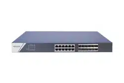
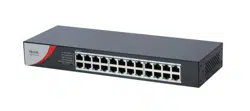
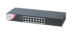
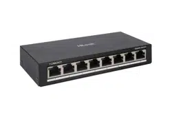
1.3 Appearance
Device appearances vary with different models. The actual device
prevails.
Front Panel
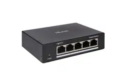
0505 series switches feature five gigabit RJ45 ports.
0505 Series
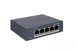
0508 series switches feature eight gigabit RJ45 ports.
0508 Series
2
Rear Panel
0505 Series
0508 Series
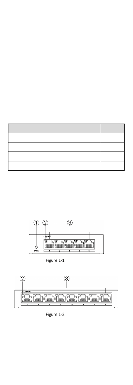
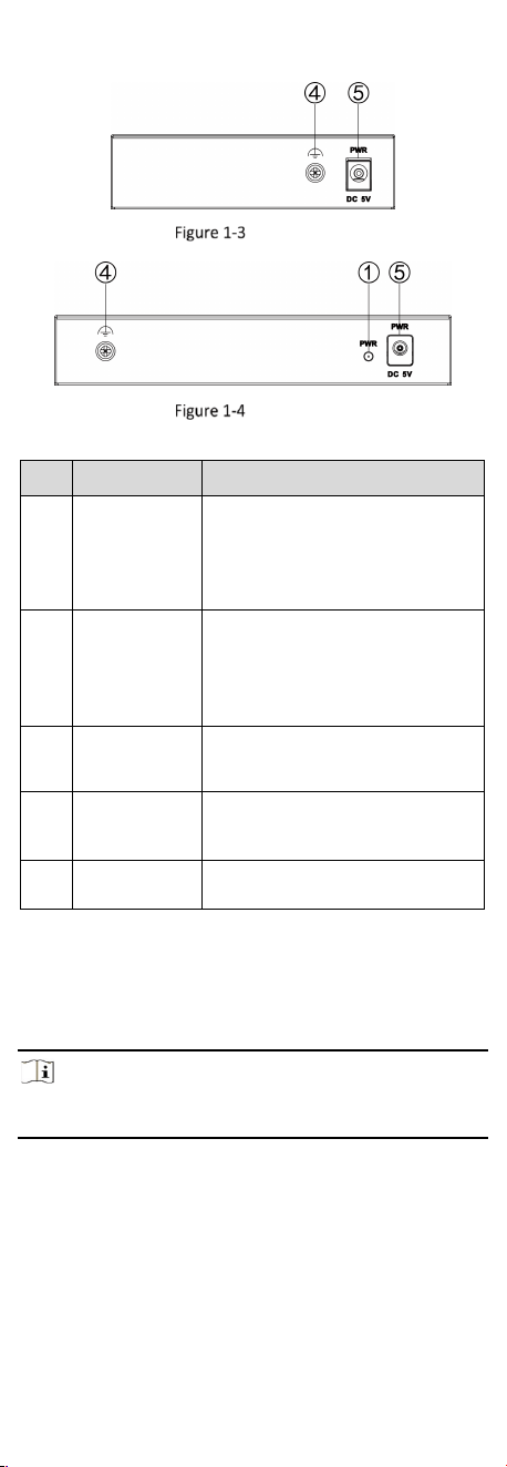
Table 1-2 Port/Indicator Description
No.
Indicator/Port
Description
①
PWR Indicator
● Solid on: The switch is powered
on normally.
● Unlit: No power supply is
connected or power supply is
abnormal.
②
LINK/ACT
Indicator
● Solid on: The port is connected.
● Flashing: The port is transmitting
data.
● Unlit: The port is disconnected or
connection is abnormal.
③
Gigabit RJ45
Port
Used for connection to another
device via a network cable.
④
Grounding
Terminal
Used for connection to a grounding
cable to protect the switch from
lightning.
⑤
Power Supply
Use the attached power adapter to
connect the switch to a socket.
2 Installation
Please select an appropriate installation method according to the
actual needs.
Note
The following figure is for illustration only. The actual device
prevails.
Before You Start
Ensure that the desktop or wall is stable and firm enough.
Keep the room well-ventilated. Leave at least 10 cm of heat
dissipation space around the device.
2.1 Desktop Placement
Place the device on the desk.
3
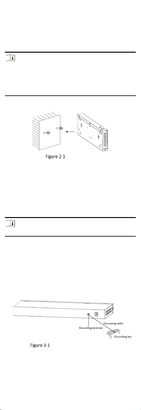
2.2 Wall Mounting
Steps
1. Check the distance between the two hanging holes at the
bottom of the device.
2. Insert two self-prepared M4 screws into the wall.
Note
●
The load-bearing capacity of the wall should be three times more
than the weight of the device.
●
Ensure that the distance between the two screws equals to the
distance between the two hanging holes.
●
Set aside at least 4 mm of the screw bodies outside the wall.
3. Align the hanging holes with the screws, and hang the device on
the screws.
Wall Mounting
3 Wiring
3.1 Connect Grounding Cable
Grounding is used to quickly release overvoltage and overcurrent
induced by lightening on the device, and to protect personal safety.
Select an appropriate grounding method according to the
installation conditions.
Note
The following figures are for your reference only.
3.1.1 With Grounding Bar
If a grounding bar is available at the installation site, follow the
steps below.
Steps
1. Connect one end of the grounding cable to the binding post on
the grounding bar.
2. Connect the other end of the grounding cable to the grounding
terminal of the device and tighten the screw.
Grounding with Grounding Bar
3.1.2 Without Grounding Bar
If there is no grounding bar but the earth is nearby and the
grounding body is allowed to be buried, follow the steps below.
Steps
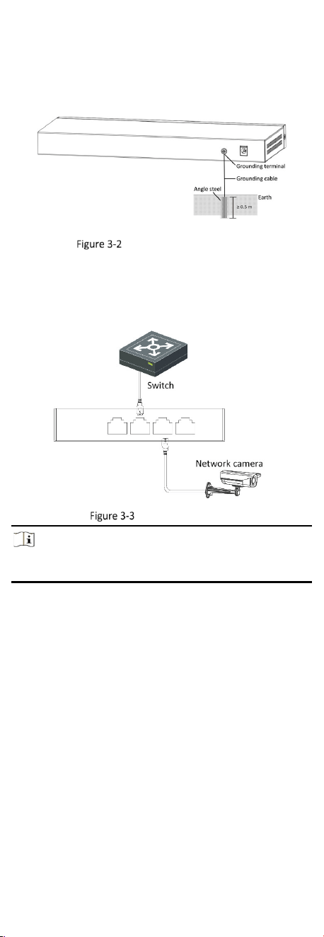
4
1. Bury an angle steel or steel pipe (≥ 0.5 m) into the earth.
2. Weld one end of the grounding cable to the angle steel or steel
pipe and embalm the welding point via electroplating or coating.
3. Connect the other end of the grounding cable to the grounding
terminal.
Grounding with Angle Steel
3.2 Connect RJ45 Port
Use a network cable to connect the device to the RJ45 port of a
peer device such as network camera (IPC), network video recorder
(NVR), switch, etc.
RJ45 Port Connection
Note
When the device is connected to a network camera (IPC), a
separate power supply is required for the IPC.
4 Device Powering-On
Please use the attached power adapter to power on the device.
Before powering on your device, make sure that:
• The operating power supply is compliant with rated input
standard.
• Port cables and grounding cables are correctly connected.
• If there is outdoor wiring, connect a lightning rod and a
lightening arrester to the cable.