www.windsterhood.com
User’s Manual
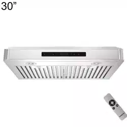
WS-2330SS
WS-2336SS
Please read this operation manual thoroughly before
using your range hood. Store it in a safe location for
when you need to reference it in the future.
NOTE: PLEASE INSPECT HOOD
IMMEDIATELY UPON RECEIVING.
CLAIM OF DAMAGE AFTER 7
DAYS OF DELIVERY WILL BE
DENIED.
This unit is designed for indoor
residential use only. DO NOT USE
OVER A WOOD GRILL OR MOUNT
IN OUTDOOR ENVIRONMENT.
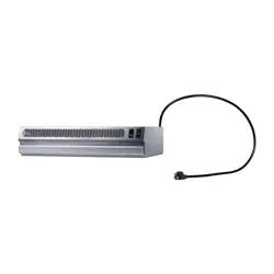
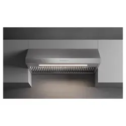
UNDER CABINET SERIES

Read all Instructions bere Installing and operating this appliance
•
The installation in this manual is intended r qualied installers, service tecicians or persons with
similar qualied background. Installation and electrical wiring must be done by qualied prossion
als and in accordance with all applicable codes and standards, including re-rated construction.
•
attempt to install this appliance yoursel Injury could result om installing the unit due to
lack o丘ppropriate electrical and technical background.
•
Range hood may have very sha edges; please wear protective gloves if it is necessary to remove any
parts r installing, cleaning or servicing.
•
Activating any switch ON bere completing installation may cause ignition or an explosion.
•
Due to the size and weight of this range hood, two people installation is recommended.
To reduce the risk of re, electric shock, or injury to persons:
•
For general ventilating use only. use to exhaust hazardous or explosive materials and va
pors.
•
The combustion air ow needed r sa operation of el-bing equipment may be aected by this
it's operation. Follow the heating equipment manucturer's guideline and saty standards such
as those published by the National Fire Protection Association(NFPA), and the American Society of
Heating, Reigeration and Air Conditioning Engineers (ASHRAE), and the local code authorities.
•
Bere servicing or cleaning unit, switch power OFF at service panel and lock service panel to pre
vent power om being switched ON accidentally.
•
Clean grease laden sfaces equently. To reduce the risk of re and to山sperse air properly, me
sure to vent air outside. vent exhaust into spaces between walls, crawl spaces, ceiling, attics
or garages.
•
Ducted fans MUST always be vented to the outdoors.
•
Use only metal ductwork and this it MUST be groded.
•
Sucient air is needed r proper combustion and exhausting of gases through the duct to prevent
back draing.
•
en cutting or drilling into wall or ceiling, be carel not to damage elecical wiring or other hid-
den utilities.
•
All elecical wiring must be properly installed, insulated and grounded.
•
Old duct work should be cleaned or replaced if necessary to avoid the possibility of a grease re.
•
Check all joints on duct work to insure proper connection and all joints should be properly taped.
•
Use is unit only in the manner intended by the manucturer. If you have questions, contact the
vendor.
To reduce the risk of a stove top grease re:
•
Keep all n, bae, spaces, lter, grease tunnel, oil container and grease-laden surfaces clean. Grease
should not be allowed to accumulate on n, bae, spaces, lter, grease tnel and oil container.
•
Always range hood ON when cooking at high heat or when cooking aming ods.
•
Use high settings on cooking range only when necessary.
•
Never leave surce units unattended at high settings. Boil overs cause smoking and greasy spillovers
that may ignite. Heat oils slowly on low or medium settings.
Page 1
Read all Instructions bere Installing and operating this appliance
•
Clean ventilating n equently.
•
Always use appropriate cooare and utensils size.
•
Always use cookware appropriate r the size of the surface element.
To reduce the risk of injury to persons in the event of a stove top grease re:
SMOTHER FLAMES with a close-tting lid, cookie sheet, or metal ay, then OFF the ber.
BECAFUL TO PREVENT BURNS. NEVER PICK UP A FLAMING ou may be bed.
KEEP FLAMMABLE OR COMBUSTIBLE MATERIAL FROM FLAMES. If the ames DO
NOT go out immediately, ECUATE AND CALL THE FIRE DEPARTMENT or dial your local
emergency service immediately.
DO NOT USE ER, including wet dishcloths or towels
—
a violent steam explosion will result.
Use an extinguisher ON if:
•
You know you have a Class A, B, C extinguisher, and you already know how to operate it.
•
The re is small and contained in the area where it is started.
•
The re department is being called.
•
You can ght the re with your back to an exit.
To reduce the risk of injury to persons in the event of a gas leaks:
•
Extinguish any open ame.
•
DO NOT on the range hood n or any type of ventilator.
•
DO NOT on the lights or any type of appliance.
•
Open all doors and windows to disperse the gas. If you still smell gas, call the gas company and re
department, or dial your local emergency service immediately.
n
h
h
e
a
sa
ppen
t
y al
if
if
t
t
e
h
rt
he
e
s
i
y
i
WARNING
m
b
ol.
nstructions
This
a
re
symb
no
Your saty and the saty of others is very important. have provided many important saty mes
sages in this manual and on your appliance. Always read and obey all saty messages. All saty mes
sages will tell you what the potential hazard is, tell you how to reduce the chance of inj, and tell you
what ca
t llowed.
his
凸
is T
t
ol alerts you to potential hazards that can hurt you and others.
All saty messages will llow the saty alert symbol and the word "WARNING".
The manufacturer anor disibur/reseer clines a responsili in e event of failure to ob
serve e insucons ven here r instaaon, manance and suble use e produc
The manufacturer anor disibur/reseer furer cnes a responsi r iu e to neg
gence and the warran of e unit automacay pires due improper maintenance.
e manufacturer anor disibutor/reseer wi not be he respons for any damages to per
sonal proper or real este or a bodily injuries wheer caused directly or indirectly by e range
hoo
Page 2

Table of Contents
Page 3
Tools Needed ............................................................................. 4
P
arts Supplied ........................................................................... 5
Venting Requirements
............................................................... 6
Calculating Vent System Length ...............................................7
Venting Methods ........................................................................ 8
Ductless Conversion/Electrical Req uirements ...................... 9
Preparation ............................................................................... 10
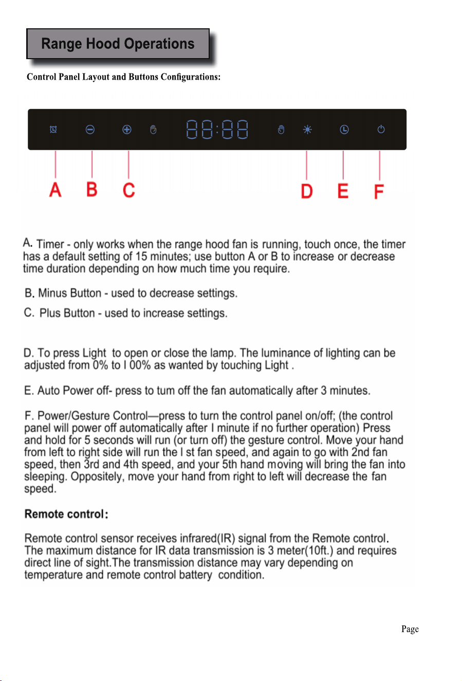
Range Hood Operations .......................................................... 12
Troubleshooting ...................................................................... 13
Use and Care Information/Specifications ............................. 14
Measurements and Diagrams ................................................. 15
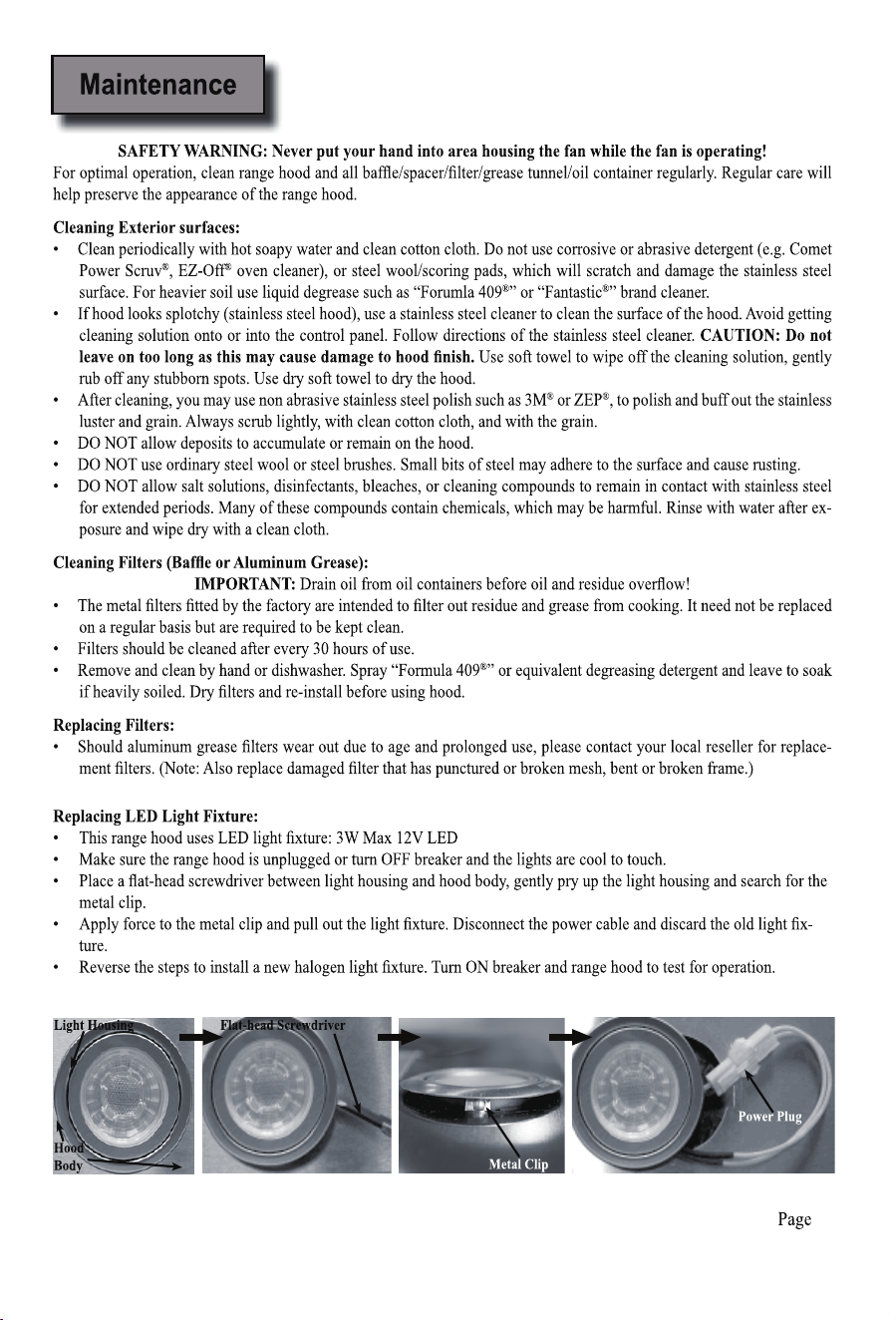
Maintenance .............................................................................. 16
WARRANTY/CONTACT US .......................................................... 17
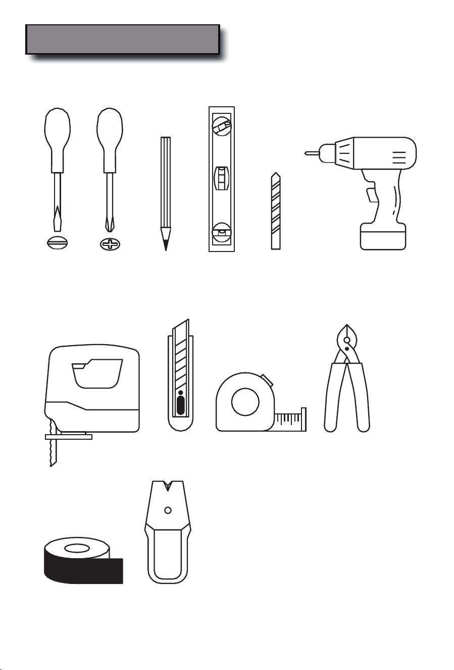
Tools Needed
Page4
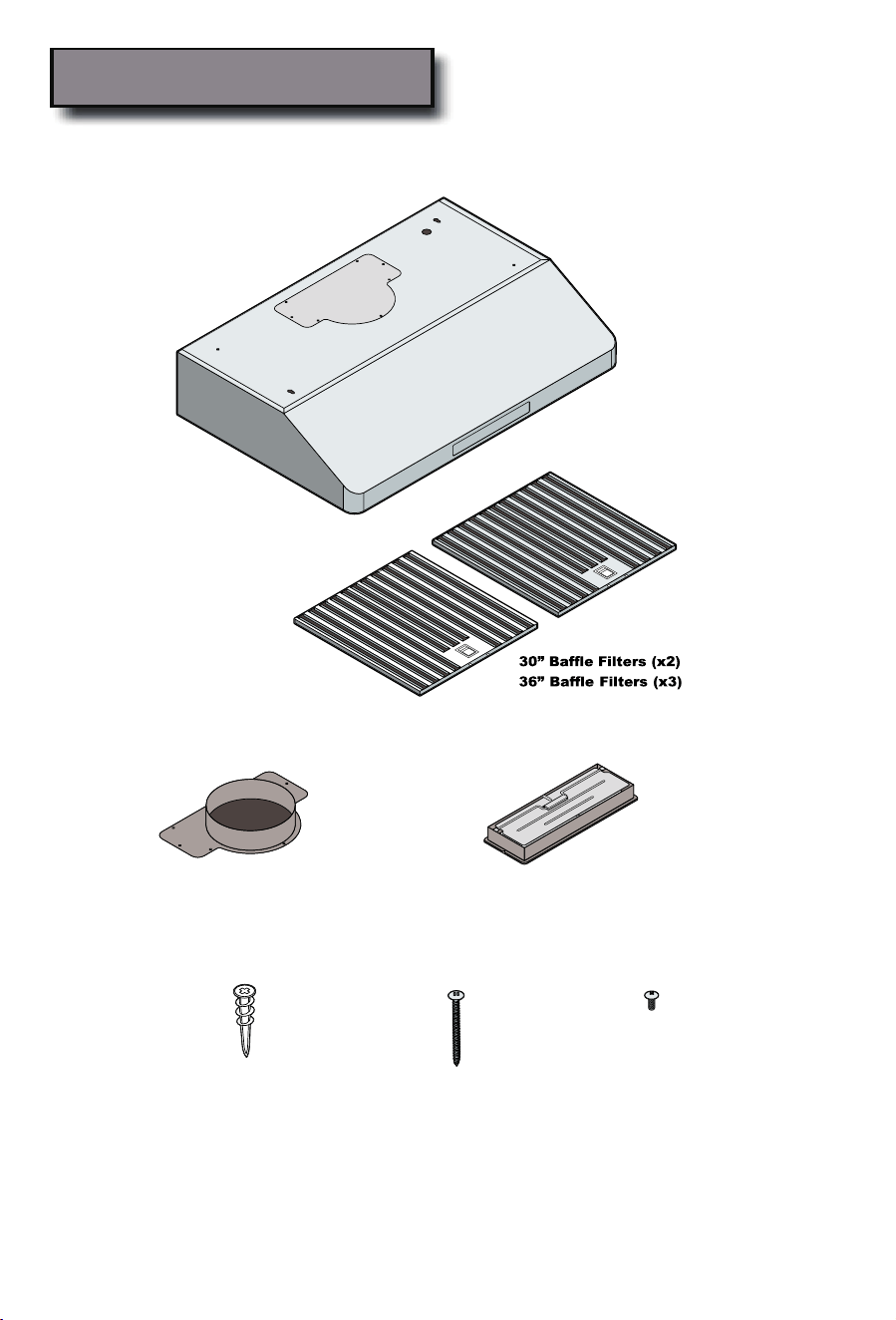
Parts Supplied:
Page
5
Round Exhaust /VentAdapter
(For vertical venting)
Rectangular Exhaust/Vent Adapter
(For vertical or horizontal venting)
Qty:12PCS
(For sheet rock only)
Qty:12PCS
Qty:6PCS
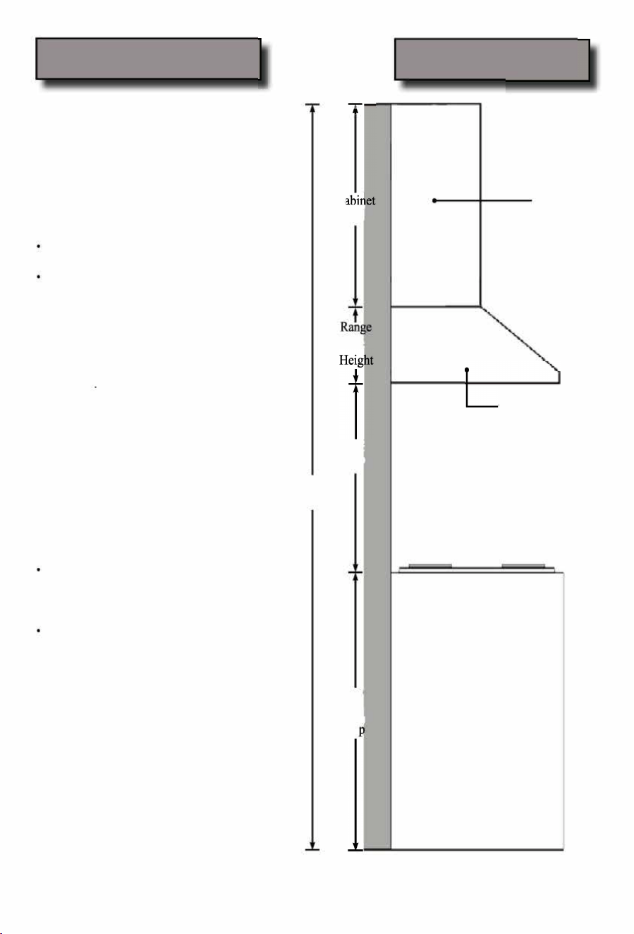
Venting Requirements
Height & Clearance
•
nt system must terminate to the outside
(roof or side wall).
•
DO NOT terminate the vent system in an at
tic or other enclosed area.
•
DO NOT use 4" (10.2 cm) lay-type wall
caps.
•
Use metal/aluminum vent only. Rigid metal/
aluminum vent is recommended.
•
DO NOT use plastic vent.
Always keep the duct clean to ensure proper
airow.
Calculate the llowing gures bere instal
lation:
1. Distance m the oor to the ceiling
2. Distance beeen the oor to the coun
tertop/stove.
3. Distance beeen the counterttove
to the range hood commend* 27" to
3
0
'
4. Height of hood and duct coverabinet.
For the most ecient & quiet operation:
•
A distance of 27" to 30" is recommended*
between stove top and the bottom of range
hood.
•
It is recommended that the range hood be
vented vertically through the roof through 6"
(15.3 cm) or bigger round metal/aluminum
vent work.
•
The size of the vent should be unirm.
Use no more than three 90
°
elbows.
•
Make sure there is a minim of 24" (61
cm) of saight vent between the elbows if
more than one elbow is used.
DO NOT install two elbows together.
•
The length of vent system and number of
elbows should be kept to a m血mum to pro
vide ecient performance.
•
The vent system must have a dper. If
roof or wall cap has a dper, DO NOT
use damper (if supplied) on top of the range
hood.
•
Use silver tape or duct tape to seal all joints
in the vent system.
•
Use caulking to seal exterior wall or roof
opening around the cap.
• Due to dierent ceiling height cogations, rec
on皿ended height may not be applicable.
一星
C
'
Heig比
Hoo
Min: 27"
Max: 30"
Ceiling
Height
3
6
'
Counr
T
o
•
Cabinet
Under Cabinet
Range hood
Coteop/Stove
Page 6
IMPORTANT:
•
A minimum of 6" round (standard r this range hood) or 3-1/4 x 10" rectangular duct(purchased separate
ly) must be used to maintain maximum airow eciency.
•
Always use rigid type metal/aluminum ducts if available to maximize airow when connecting to provided
duct.
•
Please use Duct Run lculation below to compute total available ct r when using elbows, transitions
and caps.
•
ALWAYS, when possible, reduce the number or transitions and s. Iflong duct run is required, increase
duct size om 6" to 7" or 8". If a reducer is used, install a long reducer instead of a pancake reducer. Reduc
ing duct size will restrict airow and decrease airow, thus reduce duct size as r away om opening as
possible.
•
If tus or ansitions are required: Install as far aw om opening and as far apart, between 2, as possible.
•
Minimum mount height between stove top to hood bottom should be no less than 27-inch*.
•
Maximum mount height between stove top to hood bottom should be no higher than 30-inch*.
•
It is important to install the hood at the proper mounting height. Hoods mounted too low could result in heat
damage and re hazard; while hoods moted too high will be hard to reach and will loose its perrmance
and eciency.
•
If available, also rer to stove top manucturer's height clearance requirements and recon皿ended hood
mounting height above range.
• Due to dierent ceilg heit confiations, recoended height may not be applicable
Minimum Duct Size:
•
Round - 6" minimum
•
Rectangular - 3-1/4 x 10" minimum (requires a provided 3-l/4x!O" adaptor)
Calculating Vent System Length
calculate the length of the system you need, deduct the equivalent et r each vent piece used in the system
om the recommended maximum duct r.
Duct Run Calculation:
Recommended maximum r
6" or 3-1/4 x 10" duct
50
Vent piece deduction
Each 90
°
elbow used
9
Each 45
°
elbow used
Each 6" to 3/14 x 1 O" transition used
7
Side wall cap with damper
0
Roof cap
0
Duct Run Cauaon amp:
One cap, o
90
°
elbow, and one 4
5
°
elbow ed:
O + 9 + 9 + 5=益且
use
d
Deduct 23o
m 50
,
丑i
mimum available r
straight duct n.
Page 7
IMPONT:
•
NEVER exhaust air or terminate duct work into spaces between walls, crawl spaces, ceiling, attics or
garages. All exhaust must be ducted to the outside.
•
Use metal/aluminum duct work only.
•
Fasten all coections with sheet metal screws and tape all joints with certied Silver Tape or Duct e.
•
Use caulking to seal exterior wall or roof opening around the cap.
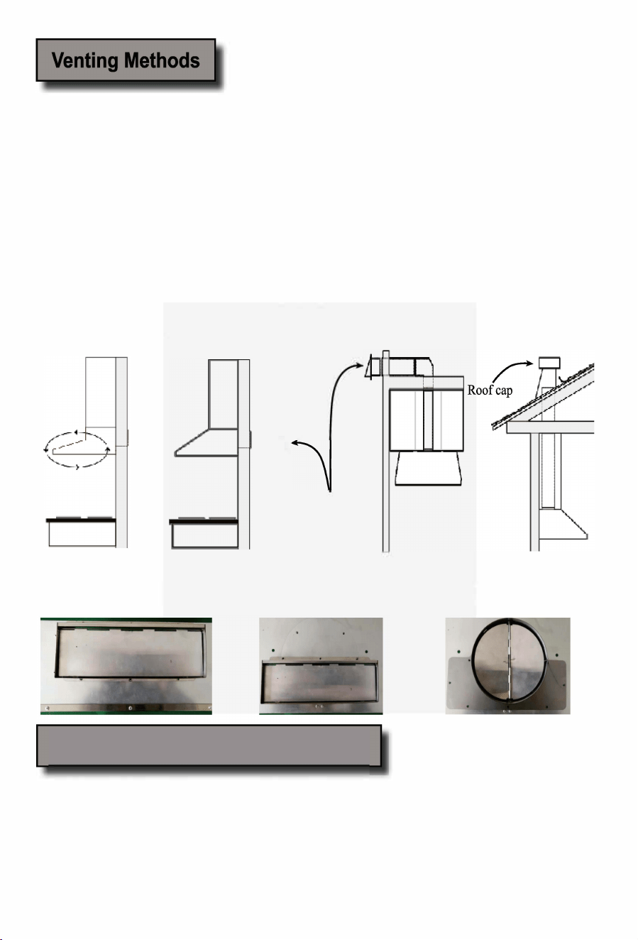
nting Methods:
•
Vent work can terminate either through the roof or wall. To vent through a wall, a 90
°
elbow may be needed.
•
This range hood is ctory set r vertical venting using rod or rectangular vent adapter but can be con
verted to horizontal venting by swapping the round vent adapter on top with rectangul vent adapter behind
the range hood as shown below:
Option
1:
Option 2: Option 3:
Recirculate venting
Horizontal wall venting
Vertical roof venting
(available with 2000 Class only)
Ty
pe 1
:
3-1/4 x 10-inch rectangular vent
adapter behind e range hood.
卧
pe
2:
Side wall cap
3-1/4 x 10-inch rectangular vent
adapter on top of the range hood.
Optional Charcoal Filter Installation
pe 3:
6-inch round vent adapter on top
of the range hood.
NOTE: The charcoal lters are preinstalled if you purchased the range hood with re-circulating kit om us.
1. Remove aluminum lters on hood.
2. Position the charcoal lter onto the motor and until it locks. Re-install aluminum lters.
3. Charcoal lters must be replaced aer 120 hours of use (or approximately every 2 to 3 months based on the
average of 1 to 2 hours of daily cooking time). ailable at your local resellers.
Page 8

Ductless Conversion
• Ductless conversion is intended r applications where an exhaust duct work is not possible to be installed.
When converted, the hood nctions as a piing hood rather than an exhaust hood. Fumes and exhaust
om cooking is drawn and ltered by a set of charcoal lters. The air is then puried and re-circulated back
within e home.
• We recommend to ALS exhaust air outside of the home by employing existing or installing new duct
work, if possible. Only when the exhaust option is not possible should you recourse to converting the hood
into a piing it.
• When converted to be a "puriing" unit, a set of charcoal lters and an a订-diverter are required in addition to
its standard aluminum lter set. ailable at yo local resellers. The standard aluminum lters are intended
to capture residue om cooking, the optional charcoal lters help to puri mes exhausted om cooking,
and the optional air-diverter redirects ltered clean air back to the house.
Electrical Requi『ements
IMPORTANT: Observe all goveing codes and ordinances.
(Please consult with a qualied electrician r 220-Volt 50 Hz voltage)
It is the customer's responsibility:
•
contact a qualied electrical installe
•
assure that the elecical installation is adequate and in conrmance wi National Elecical Code, ANSI/
NFPA 70 - latest edition*, or CSA Standards C22. 1-94, Canadian Electrical Code, Part 1 and C22. 2 No.
O-M91 - latest edition** and all local codes and ordinances.
If codes permit and a separate grod wire is used, it is recommended that a qualied elecician determine that
the ground path is adequate.
A 120-lt, 60 Hz, AC-only, sed elecical supply is required on a separate 15-amp circuit, sed on both sides
of the line.
DO NOT ground to a gas pipe.
Check with a qualied elecician if you are not sure that the range hood is properly groded.
DO NOT have a se in the neutral or ground circuit.
IMPORTT: Save this Installation Guide r elecical inspector's use.
The range hood must be connected wi copper wire/plug only.
The range hood should be connected directly to the sed disconnect (or circuit breaker) box through exible
armored or non-metallic sheathed copper cable. A U.L. - or C.S.A. - listed sain relief must be provided at each
end of the power supply cable.
Wire sizes (copper wire only) and connections must conrm with the rating of the appliance as specied on
the model/serial rating label. Wire sizes must conrm to the requirements of the National Elecical Code
ANSIF 70 — latest edition*, or CSA Standards C22. 1-94, Canadian Elecical Code Part 1 and C22.
2 No. O-M91 - latest edition** and all local codes and ordinances. A U.L. - or C.S.A. - listed conduit con
nector must be provided at each end of the power supply cable (at e range hood and at the junction box).
Copies of the standds listed may be obtained om:
• National Fe Protection
A
ssociation
Bach Pk
如n, Massachuses 02269
**
C
S
A
teational
8501 East Pleast lley Road
C
leveld, Ohio 44131-5575
Page 9
Preparation
Advanced Preparations:
Be familiar with the conols of the range hood by reading
through Range Hood Operaons, Page 13-14.
Place e range hood on a at, stable surce. Connect the
range hood to a designated standard outlet and on the
range hood. ri all operations of the range hood by rer
ring to Range od Operations, Page 13-14.
t\WARNING
Excessive Weight
Require three or more person to move and
install this range hood. Spinal or other bodi
ly injuries could occur if it is not llowed.
Place all supplied parts and required hardware on a at, sta
ble surface and veri the existence of all supplied parts listed on Page 4.
Carelly remove the white plastic protective coat om the range hood, if any.
Preparations:
NOTE: To avoid damage to your hood, prevent debris om entering the vent
opening.
入WARNING
Severe Injury
Rotating fan can cause severe
inju. Stay clear of fan when
motor is running.
• Decide the location of the venting pipe om the hood to the outside. Rer to Venting Metho on Page 7.
• A straight, short vent r will allow the hood to perform more eciently.
• Try to avoid as many ansitions, elbows, and long run as possible. This may reduce the perrmance of the
hood.
• IMPORTANT: Peel white plastic protective coat o the hood, if any.
• Use silver tape or duct tape to seal joints between pipe sections.
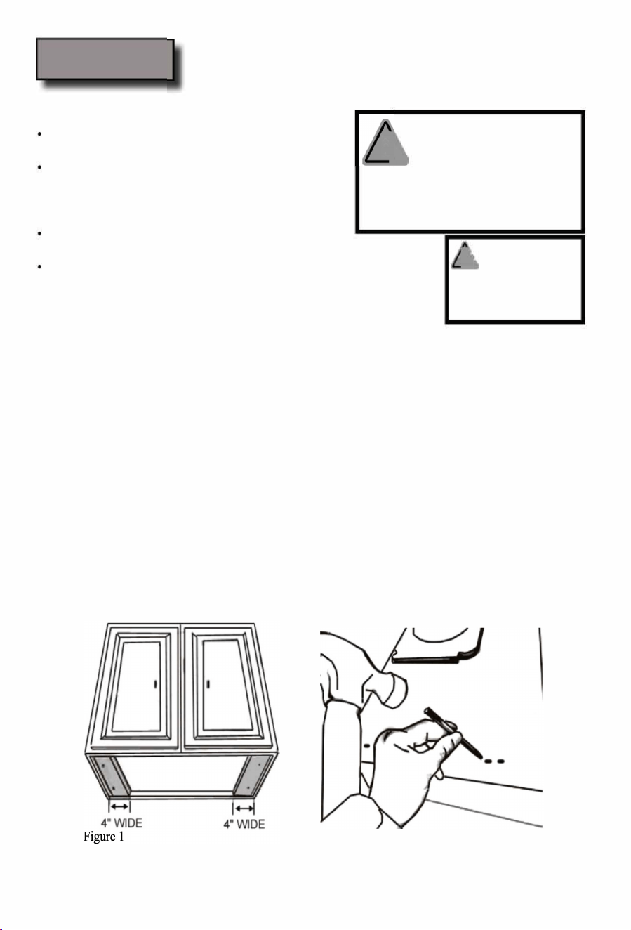
• For installing under the cabinet with recessed bottom, attach 4-inch wide wood ller strips (not provided) on
each side. Rer to Fi
e 1.
• Using references in Installation on Page 10-12 and Measurements and Diaams on Page 17-21, create ac
cess opening r electrical wires and hood exhaust under the cabinet.
CAUTION: If moving the cooking range is necessary to install the hood, turn OFF the power on an elec
tric range at the main electrical box. SHUT OFF THE GAS BEFORE MOVING A GAS GE.
• Puncture the knockout holes (r moting under the cabinet) on the hood as shown in Fi
e 2.
• If necessary, attach two rubber stands with 3M adhesive tapes to the back coers of the hood.
Fi
e 2
Page 10
Installation
Installations (rer to Page 4 r parts):
Measure the distance between stove top and the bottom of
range hood. A distance of27" to 30" is recommended*.
* Due to derent ceiling height corations, recommend
ed height may not be applicable
1. u have two ways (A: Vertical nting, or B: Horizontal nting) to mount this range hood:
1.
Determine venting method as shown on Page 7 and proceed if you would like to vent vertically.
2.
Using rerences in ight & Clearance on Page 5-6, Measuments and Diagrams on Page 17-21,
Fi
e 3 and Fi
e 4 on next page, determine and clearly mark a centerline on the bottom of the cabi
net.
3.
Draw elecical wires through cabinet access opening on top of the range hood, center the hood beneath
the cabinet and ush with the ont of the cabinet.
4.
From inside of the hood, place hood mounting screws into the exact center of each knockout hole and
sece to cabinet bottom. Finish tightening all screws til secure. Be carel when using electrical
screwdriver, damage to the range hood may occur. Skip Part B below and proceed to Step 2.
CAUTION: Make certain the range hood is secure bere releasing!
1.
Determine venting method as shown on Page 7 and proceed if you would like to vent horizontally.
2.
Using rerences in ight & Clearance on Page 5-6, Measuments and Diagrams on Page 17-21,
Fi
e 5 and Fi
e 6 on next page, determine and clearly mark a centerline on the wall.
3.
Punchure the knockout wire access hole and rear duct access hole on the back of the hood, draw electri
cal wires through the wire access hole and attach rectangular vent adapter.
4.
Draw elecical wires through the access opening on the wall behind e range hood (Fi
e 6), center
the hood beneath the cabinet and ush with the ont of the cabinet.
5.
From inside of the hood, place hood mounting screws into the exact center of each knockout hole and
secure to the wall. Finish tightening all screws until secure. Be carel when using electrical screw
iver, damage to the range hood may occur.
CAUTION: Make certain the range hood is secure bere releasing!
2. For safety purpose, pre-drilled mounting holes are provided through the back of the hood. For a more secure
installation, use as many mounting holes as needed to secure om the inside of hood.
1. Use 6" round steel pipe (llow building codes in your area) to coect the exhaust on the hood to the duct-
work above. Use silver tape or duct tape to make all joints secure and air tight. Rer to Fi
e 6.
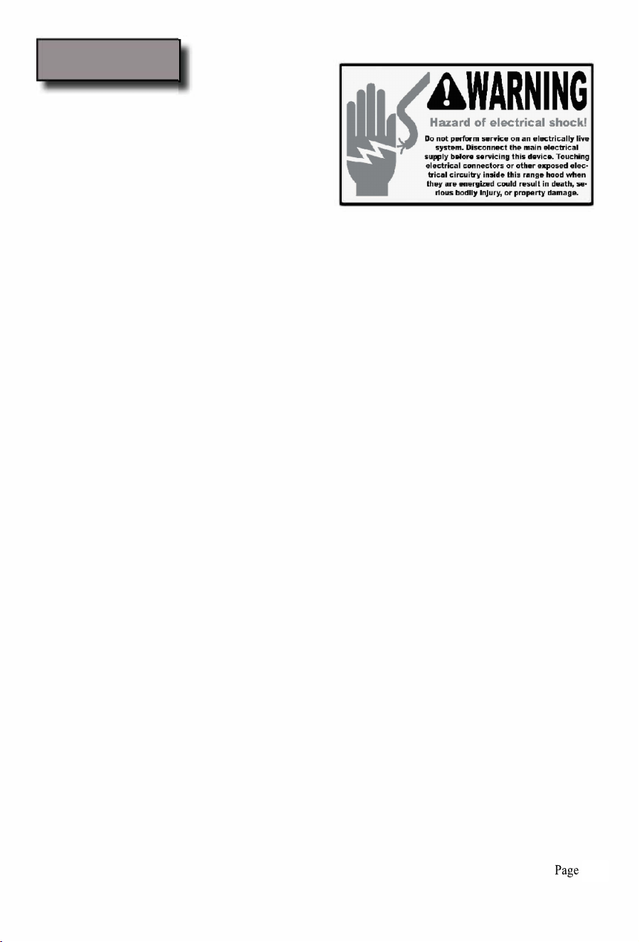
SAFETY WARNING: Risk of electrical shock. this range hood must be properly grounded. Make sure this
is done by qualied electrician in accordance with all applicable national and local electrical codes. Bere
connecting wires, switch power o at service panel and lock service panel to prevent power om being
switched on accidentally.
1. Coect the range hood to a designated standard outlet or cut o the plug and connect three wires(black,
white and green) to house wires and cap with wire connectors. Connect according to colors (i.e. black to
black, white to white, and green to green).
2. Store excess wires in the wiring box.
3. Power ON using control panel (rer to Range od Operations on Page 13-14). Check all lights and
n operations.
4. Me se to leave this Installation Guide r the homeowner.
11
12
13
256W
250W
2A
4 Levels
503CFM
Dual Motors
120V/60Hz(USA & Canada standard)
14
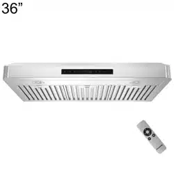
Electronic Touch Control Panel
Stainless Steel or Seamless Steel

16

17
LIMITED WARRANTY
Windster Hoods Inc. warrants its product against defects in material or workmanship as
follows:
Parts: Windster Hoods, Inc. will supply, at no charge, new or rebuilt replacements in
exchange for defective parts for a period of two (2) years. After the warranty period,
consumer will be responsible for all parts costs. During the "parts" warranty period,
there will be no charge for parts.
Motor: Windster Hoods, Inc. will also provide, at no charge, new or rebuilt motor parts
in exchange for defective parts for a period of five (5) years, excluding motor cages.
After the warranty period, consumer will be responsible for all motor parts costs. During
the “motor” warranty period, there will be no charge for motor parts.
purchased the unit for service.
Windster Hoods, Inc. will not be held liable for removal and/or installation fees of the
malfunctioning, defective, and/or replacement unit.
Please keep the original sales receipt, as it will constitute as your proof of purchase.
Consumer must provide the serial number and the original sales receipt to submit a
warranty claim. Warranty claims submitted without serial number and original sales
receipt will be denied. This warranty applies only to products purchased and serviced in
the United States.
For products purchased in Canada, please contact your local retailer where you
WARRANTY / CONTACT US

18
*Windster Hoods, Inc. reserves the right to determine the validity of your warranty claim.
WHAT IS NOT COVERED BY MANUFACTURER WARRANTY
1. Damages resulting from any of the following:
a. Im
proper installation or maintenance
b. A
ny repair, modification, alteration or adjustment not authorized by the
manufacturer or an authorized service dealer
c. Misuse, accidents, and/or neglect
d. Incorrect electric current, voltage or power supply
e. Improper s
etting of any control (Pressing multiple selections at the
s
ame time)
f. Improper chemical cleaning (commercial or industrial cleaning agents)
2. P
roducts purchased for use in an outdoor, commercial, and/or industrial setting
(such as in a hotel, office, restaurant, or other business)
3. Damage res
ulting from natural disasters (earthquake, flood, storm, etc.)
4. Regular maintenance for the product
5. Wear and maintenance items such as:
a. Aluminum Filters, Baffle Filters, Charcoal Filters, Mesh Filters, Oil
c
ups, Lighting bulbs, light fixtures etc.
6. Corrosion
7. Oil Cup
8. Motor Cage
9. Light Bulbs
10. Remote control
No returns refunds exchanges if the hood
Is missing parts
Been Installed
Been Used
WARRANTY / CONTACT US

CONTACT US
Windster Hoods, Inc.
www.windsterhood.com
Information subject to change without notice
19
WARRANTY / CONTACT US