
METALWORKING LATHE 550MM BETWEEN
CENTRES
MODEL NO: SM27.V3
Thank you for purchasing a Sealey product. Manufactured to a high standard, this product will, if used according to these
instructions, and properly maintained, give you years of trouble free performance.
IMPORTANT: PLEASE READ THESE INSTRUCTIONS CAREFULLY. NOTE THE SAFE OPERATIONAL REQUIREMENTS, WARNINGS & CAUTIONS. USE
THE PRODUCT CORRECTLY AND WITH CARE FOR THE PURPOSE FOR WHICH IT IS INTENDED. FAILURE TO DO SO MAY CAUSE DAMAGE AND/OR
PERSONAL INJURY AND WILL INVALIDATE THE WARRANTY. KEEP THESE INSTRUCTIONS SAFE FOR FUTURE USE.
1. SAFETY
NOTE: The lathe is tted with three safety devices. A Emergency Stop Button (g.1.19) is mounted on the main control panel and
two interlocks operate if either the gear box cover or head stock guard are opened.
1.1. ELECTRICAL SAFETY
WARNING! It is the user’s responsibility to check the following:
Check all electrical equipment and appliances to ensure that they are safe before using.
Inspect power supply leads, plugs and all electrical connections for wear and damage.
Ensure that the insulation on all cables and on the appliance is safe before connecting it to the power supply.
8 DO NOT use worn or damaged cables, plugs or connectors.
9 Ensure that any faulty item is repaired or is replaced immediately by a qualied electrician.
9 If the cable or plug is damaged during use, switch o the electricity supply and remove from use.
Ensurethatrepairsarecarriedoutbyaqualiedelectrician.
9 Sealey recommend that an RCD (Residual Current Device) is used with all electrical products.
Important: Ensure that the voltage rating on the appliance suits the power supply to be used and that the plug is tted with the
correct fuse.
8 DO NOT pull or carry the appliance by the power cable.
8 DO NOT pull the plug from the socket by the cable.
1.2. GENERAL SAFETY
NOTE: Only trained users to operate the lathe. If inexperienced, seek suitable training.
WARNING! The lathe is heavy (145kg). Ensure either lifting equipment or sufficient handlers are used when installing / manoeuvring.
Handle with care and ensure the load is well balanced.
WARNING! Disconnect the lathe from the mains power and ensure that the chuck is at a complete standstill before attempting to
change accessories, service or perform any maintenance.
WARNING! Before each use check that chuck, cutting tool and tailstock are secure and not worn or damaged. If any part of the lathe
is worn or damaged replace immediately.
WARNING! Keep guard and holding fixings in place, tight and in good working order. Check regularly for damaged parts.
WARNING! Wear approved safety eye protection and, if oil mist is generated, respiratory protection.
WARNING! DO NOT switch on the lathe whilst the cutting tool is in contact with the workpiece. Bring the cutting tool gradually to the
workpiece.
WARNING! DO NOT use the lathe where there are flammable liquids, solids or gases such as petrol, paint solvents, waste wiping rags .
8 DO NOT use the lathe for a task it is not designed to perform.
8 DO NOT allow untrained persons to operate the lathe.
8 DO NOT get the lathe wet or use in damp or wet locations, or areas where there is condensation.
8 DO NOT operate the lathe if any parts are missing or damaged as this may cause failure and/or personal injury.
8 DO NOT lift or remove the chuck guard whilst the lathe is in use.
8 DO NOT touch the workpiece close to the cut as it will be very hot. Allow it to cool first.
8 DO NOT leave the lathe running unattended.
8 DO NOT operate the lathe when you are tired or under the influence of alcohol, drugs or intoxicating medication.
9 Maintain the lathe in good condition (use an authorised service agent).
9 Replace or repair damaged parts. Use recommended parts only. Unauthorised parts may be dangerous and will invalidate the
warranty.
9 Locate the lathe in a suitable area. Ensure that the mounting surface is flat and firm. Keep the area clean and tidy and free from
unrelated materials, and ensure that there is adequate lighting. Allow sufficient space around lathe installation to allow access.
9 If the lathe is bench mounted fix securely in place using suitable fixings.
9 Keep the lathe clean for best and safest performance.
9 A guard that is damaged or missing must be repaired or replaced before the tool is next used. The safety guard is a mandatory fitting
when the lathe is used in premises covered by the Health & Safety at Work Act.
9 Keep a minimum distance on 1 metre between the operator and the vision panels.
9 Remove adjusting keys and wrenches from the lathe and its vicinity before turning it on.
9 Remove ill fitting clothing. Remove ties, watches, rings and other loose jewellery and clothing, and contain long hair.
Original Language Version
© Jack Sealey Limited
Refer to
instructions
Wear eye
protection
SM27.V3 Issue 1 9/12/24
Wear safety
gloves
Warning.
Hot surfaces
Wear protective
clothing
Wear Safety
Footwear
Wear ear
protection
Warning.
Electricity

9 Keep hands and body clear of the workpiece when operating the lathe.
9 Maintain correct balance and footing. Ensure that the floor is not slippery and wear non-slip shoes.
9 Keep children and unauthorised persons away from the work area.
9 Avoid unintentional starting of the lathe. If entrapment of persons occurs, press Emergency Stop button (fig.1.19).
9 Clean Head Stock and Chip viewing panels (fig.1.3, fig1.5) with mild detergent and clean cloth regularly or replace if required. Remove
screws to enable replacement with genuine spares if panels are required. DO NOT use lathe without these panels in place.
WARNING: Tools can be hot after use.
WARNING: Processing materials such as aluminium or magnesium can cause fire, explosion or noxious dust.
WARNING: machining unbalanced workpieces may create an ejection hazard and that the way to minimize the risk is to counter balance
or machine at reduced speeds.
9 When not in use, switch off the lathe and isolate it from the power supply.
9 Should fire fighting be required, refer to MSDS.
NOTE: The gures quoted are emission levels and are not necessarily safe working levels. Whilst there is a correlation between the
emission and exposure levels, this cannot be used reliably to determine whether or not further precautions are required.
Factors that inuence the actual level of exposure of the workforce include the characteristics of the work room and the other sources
of noise, i.e. the number of machines and other adjacent processes and the length of time for which an operator is exposed to the
noise. Also, the permissible exposure level can vary from country to country. This information, however, will enable the user of the
machine to make a better evaluation of the hazard and risk.
2. INTRODUCTION
Quality workshop lathe suitable for a wide range of turning and drilling applications. Features power feed for even surface nish and thread
cutting. 4-Way tool post mounted on compound slide mechanism enables fast interchange of cutting tools with accurate feed. Powered by 550W
motor through innitely variable speed gearbox. SM27ST stand is an optional accessory and is available to be purchased separately.
3. SPECIFICATION
Model No.: .............................................................. SM27.V3
Centre Height Over Table: .......................................... 120mm
Centre Height Over Saddle ........................................ 110mm
Distance Between Centres: ........................................ 550mm
Spindle Bore: ............................................................ Ø26mm
Speed Range: .................................................100 - 2000rpm
Nett Weight: ................................................................. 145kg
Plug Type: ................................................................3-Pin BS
Power Supply Cable Length: ............................................. 3m
4. CONTENTS
WARNING! Safe physical handling will require two people.
4.1. Unpack the product and check that all components and tools are present and undamaged. If any problem is noted, contact your supplier
immediately.
4.2. STORAGE: Packaging materials should be retained especially during the Warranty period in case the product needs to be returned.
Store in a clean and dry environment.
4.3. The machine has been coated with grease to protect it in shipping. Remove the coating with commercial degreaser, kerosene or similar
solvent before use. After degreasing coat the machined surfaces with machine oil.
4.4. Position the lathe on a sturdy workbench or on the optional stand (Model No. SM27ST). The lathe should be bolted directly to the
workbench or stand through the holes provided in the bed. (M10x40mm nuts, bolts and washers supplied with SM27ST stand).
NOTE: Although the safety instructions and operating manuals for our products contain extensive instructions for the safe working with
power tools, every power tool involves a certain residual risk that cannot be completely avoided.
NOTE: It is assumed that the operator has experience of machining practice and these instructions are intended only to describe the
features of the lathe. If you have no experience of machining it is recommended that you undertake training before using this machine.
NOTE: It is assumed that the operator has experience of machining practice and these instructions are intended only to describe the
features of the lathe. If you have no experience of machining, it is recommended that you undertake training before using this machine.
Head Stock Taper: ..........................................................MT4
Tail Stock Taper: ..............................................................MT2
Tail Stock Travel: .......................................................... 70mm
Metric Pitch Quantity: ......................................................... 12
Metric Pitch Range: ..................................................0.4-3mm
Inch Pitch Quantity: .............................................................. 8
Inch Pitch Range: ...................................................... 10-44tpi
Motor Power:.................................................................550W
Supply: ...........................................................................230V
Noise Pressure: ......................................................<70dB(A)
Noise Power:...........................................................<80dB(A)
3mm Allen Wrench
4mm Allen Wrench
5mm Allen Wrench
6mm Allen Wrench
5.5/7mm Combo Wrench
8/10mm Combo Wrench
12/14mm Combo Wrench
17/19mm Combo Wrench
Dead Center MT#2
Dead Center MT#3
Fixed-Shaft Gear 40T
45-52 Round Nut Wrench
Fuse
Bench Lathe
3 Outside Jaws
Lathe Chuck Key
30T Gear
40T Gear
42T Gear
50T Gear
52T Gear
60T Gear
66T Gear
70T Gear
75T Gear
80T Gear
Square Head Wrench
Original Language Version
© Jack Sealey Limited
SM27.V3 Issue 1 9/12/24
4.5. The machine has been coated with grease to protect it in shipping. Remove the coating with commercial degreaser, kerosene or similar
solvent before use. After degreasing coat the machined surfaces with machine oil.
4.6. INITIAL TEST RUN
WARNING! Before operating the lathe, ensure that you are wearing approved safety goggles and PPE to protect yourself from swarf and
metal particles. If using cutting oil or coolant, a face mask may be necessary to avoid breathing any vapour generated. Ensure that all
other safety instructions in Section 1 are followed carefully.
NOTE: The lathe is tted with three safety devices. An Emergency Stop switch (g.1.19) is mounted on the main control panel and two
interlocks operate if either the gear box cover (g.1.21) or head stock guard (g.1.3) are opened.
NOTE: If the Fault light (g.1.17) is lit, ensure guards and gear housing door and their interlocks are engaged. If the Fault light is still lit
DO NOT use the lathe consult a suitably qualied engineer.
4.6.1. Make sure that there is NOT a chuck key inserted in the chuck, and that the lathe eye shield is in the down position over the lathe
chuck. Make this step a habit that you per form every time you start the lathe.
4.6.2. Familiarize yourself with the lathe controls shown in Fig.1 above. Make sure the STOP button is all the way down before
continuing and before any operation of the lathe is undertaken.
4.6.3. Plug the lathe into the power outlet.
4.6.4. Move the automatic carriage feed lever up to the disen gage mode. It is important that the carriage feed is NOT moving and is in the
neutral position until later.
4.6.5. Set the rotational speed control knob to the lowest 7 o’clock position.
4.6.6. Turn the Power switch to the “ON” position. The green lathe power indicator light should light up. Note-If it is does not light up,
unplug the machine and check the fuse, your power source, and the connec tions on the machine before attempting to start the lathe.
4.6.7. Turn the FWD/REV switch (g.1.18) anticlockwise. This should make the lathe chuck turn clockwise when you start the machine.
4.6.8. Stand to the side of the lathe chuck line of rotation and slowly rotate the speed control . If the carriage starts moving,
immediately push the STOP button and dis engage the automatic carriage feed lever, then restart the lathe.
4.6.9. Allow the lathe to run for at least two full min utes to make sure it is running satisfactorily.
4.6.10. Operate the lathe emergency stop button to turn the lathe OFF and turn power switch (g.1.15) to the o “0” .
4.6.11. Re-engage the emergency stop button and turn power switch to the ON position.
4.6.12. Set the rotational speed control knob to the lowest setting.
4.6.13. With the lathe chuck at a complete stop, turn the FWD/REV switch (g.1.18) clockwise to make lathe chuck to rotate anticlockwise.
4.6.14. Stand to the side of the lathe chuck line of rotation and slowly rotate the speed control knob.
1
32 4 5 6 7
8
9
10
1112
13
14
15
16
17
19
20
19
18
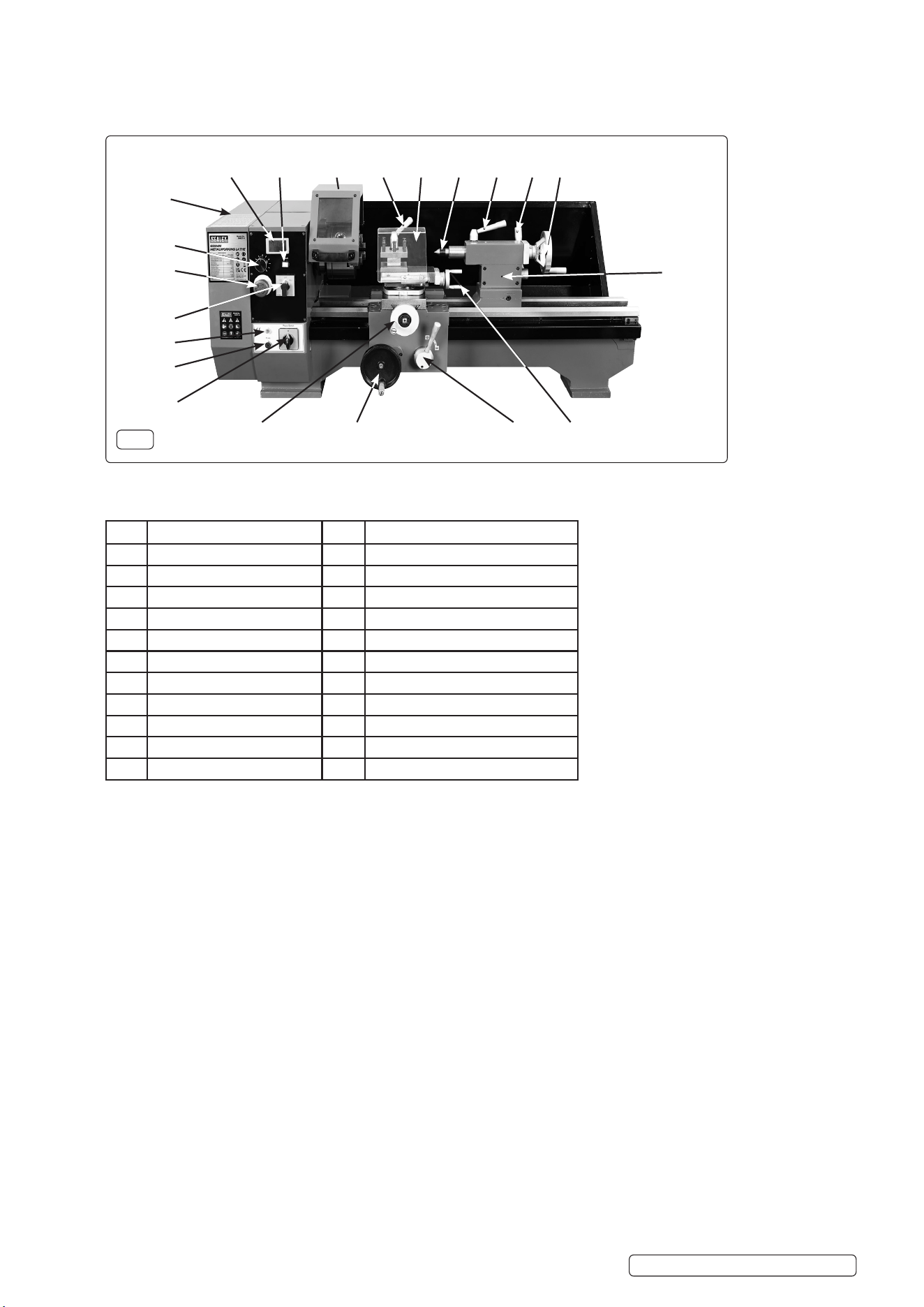
Item Description Item Description
1 LED Speed Display 12 Lead Screw Lever
2 Fault Light 13 Hand Traversing Wheel
3 Head Stock Guard 14 Cross Slide Handwheel
4 Tool Post Lock 15 On / O
5 Chip Guard 16 Fuse Holder
6 Centre 17 Fault Light
7 Centre Clamp 18 OFF / Forward / Reverse Switch
8 Tail Stock Clamp 19 Emergency Stop Button
9 Tail Stock Feed Handwheel 20 Speed Control
10 Tail Stock 21 Gear Box Cover
11 Compound Slide Handwheel
21
Fig.1
Original Language Version
© Jack Sealey Limited
SM27.V3 Issue 1 9/12/24

4.6.15. Allow the lathe to run for at least two full min utes to make sure it is running satisfactorily.
4.6.16. Press the emergency stop button to turn the lathe OFF and switch o the power using the power switch.
4.6.17. After the lathe has come to a complete stop, engage the carriage handwheel, rotate the handwheel to centre the carriage on the bed,
then disengage the handwheel by withdrawing it.
5. OPERATION
5.1. FEATURES
5.1.1. Make sure that there is NOT a chuck key inserted in the chuck, and that the lathe eye shield is in the down position over the lathe
chuck. Make this step a habit that you per form every time you start the lathe.
5.1.2. Familiarize yourself with the lathe controls shown in f\ig.1 above. Make sure the STOP button is all the way down before
continuing and before any operation of the lathe is undertaken.
5.1.3. Plug the lathe into the power outlet.
5.1.4. Move the automatic carriage feed lever up to the disen gage mode. It is important that the carriage feed is NOT moving and is in the
neutral position until later.
5.1.5. Set the rotational speed control knob to the “0”position.
5.1.6. Turn the Power switch to the “ON” position. The green lathe power indicator light should light up. Note-If it is does not light up,
unplug the machine and check the fuse, your power source, and the connec tions on the machine before attempting to start the lathe.
5.1.7. Turn the FWD/REV switch anticlockwise. This should make the lathe chuck turn clockwise when you start the machine.
5.1.8. Stand to the side of the lathe chuck line of rotation and slowly rotate the speed control . If the carriage starts moving,
immediately push the STOP button and dis engage the automatic carriage feed lever, then restart the lathe.
5.1.9. Allow the lathe to run for at least two full min utes to make sure it is running satisfactorily.
5.1.10. Operate the lathe emergency stop button to turn the lathe OFF and turn power switch to the o “0” .
5.1.11. Re-engage the emergency stop button and turn power switch to the ON position.
5.1.12. Set the rotational speed control knob to the “0”position.
5.1.13. With the lathe chuck at a complete stop, turn the FWD/REV switch clockwise to make lathe chuck to rotate anticlockwise.
5.1.14. Stand to the side of the lathe chuck line of rotation and slowly rotate the speed control knob.
5.1.15. Allow the lathe to run for at least two full min utes to make sure it is running satisfactorily.
5.1.16. Press the emergency stop button to turn the lathe OFF and switch o the power using the power switch.
5.1.17. After the lathe has come to a complete stop, engage the carriage handwheel, rotate the handwheel to centre the carriage on the bed,
then disengage the handwheel by withdrawing it
5.1.18. Engage the automatic carriage feed lever.
5.1.19. Stand to the side of the lathe chuck line of rotation, and to turn the lathe power switch ON and slowly rotate the speed control.
5.1.20. Verify that the carriage moves along the bed, and press the emergency stop button to turn the lathe OFF and switch o the power
using the power switch.
5.2. HEADSTOCK
5.2.1. The headstock spindle, which is belt driven, has a flange with mounting holes for chuck etc. and a number 3 Morse taper (internal) for a
spindle centre.
5.3. TAILSTOCK (g.1.10)
5.4. The tailstock spindle has a number 2 Morse taper (internal) for a centre or chuck. A plain centre is provided. The spindle is positioned
using the feed handle (fig.1.9) and then locked with the locking clamp handle (fig.1.8).
5.4.1. The tailstock base may be moved along the lathe bed as necessary and locked in position by the clamp (fig.1.8).
5.5. TOOLPOST
5.5.1. Up to four tools can be mounted on the tool rest. The rest can be rotated, in 90° steps, by slackening the locking handle (fig.1.4), and
slightly lifting the rest.
NOTE: Always ensure that the locking handle (fig.1.4) and tool clamp screws are tight before starting to cut.
5.5.2. The tool rest is mounted on the compound slide, which in turn is mounted on the cross slide. The compound slide can be rotated ±45°
on the cross slide to permit bevel and taper cutting. To rotate the compound slide, wind the tool rest fully to the right to reveal the two
clamp screws. Loosen the clamp screws, rotate the slide to the required angle and then tighten the clamp screws.
5.6. CHUCK
5.6.1. The chuck is supplied with internal jaws tted and a set of external jaws.
5.6.2. To remove and t jaws proceed as follows: Using the chuck key, fully wind out the tted jaws, at which point they can be pulled from
the chuck. The thread segments on the jaws are staggered and therefore the jaws are numbered 1 to 3 (on the inner end of the left
location groove) and must be tted in this sequence, in an anticlockwise direction (facing the chuck). Turn the chuck key anticlockwise
while watching the chuck thread in one of the jaw slots. When the end of the thread has just cleared the slot, stop turning the key and
insert jaw 1 into this slot. Insert the other two jaws in the other slots in sequence. Hold them under light pressure whilst turning the key
clockwise until they are picked up by the thread and start to move inwards.
5.6.3. Check that the three jaws come together correctly at the centre of the chuck. If not, repeat the procedure.
5.7. SPEED (g.1.20)
5.7.1. Chuck speed is controlled by the dial control (g.1.20). (Lowest speed is at 7 o’clock position).
5.7.2. Chuck speed is displayed in the LED display on the control panel (g.1.1).
WARNING! Before starting the lathe always confirm that nothing will contact the chuck by rotating the chuck by hand with the tool post as
far to the left as it will be during the turning operation. Make sure that the chuck guard is in place, as shown in fig.1.3.
TURNING
5.7.3. Mount the cutting tool in the tool rest such that the tip of the tool is level with, or just below, the lathe centre line. Check this by aligning
the tool tip with the point of the tailstock. The tool tip must not be above the centre line. The height of the tool tip may be adjusted by
shimming or grinding the tool.
5.7.4. Mount the workpiece in the chuck and if necessary, support the other end with the tailstock. Set the speed range, forward/reverse control and
autofeed lever to suit the job.
5.7.5. Start the lathe by slowly turning the speed control clockwise until the required turning speed is reached.
5.8. TURNING WITH AUTOFEED
5.8.1. Set the lead screw lever (fig.1.18) to FWD or REV. With the gear set as supplied, position FWD will feed the tool at 0.075mm/rev
and position REV at 0.15mm/rev. Ensure that the cross slide lock (fig. 1.14) is not applied.
5.8.2. Position the tool just to the right of the end of the workpiece and start the lathe.
Original Language Version
© Jack Sealey Limited
SM27.V3 Issue 1 9/12/24
5.8.3. Turn the auto feed lever (fig.1.12) clockwise to engage the leadscrew. The tool will now move to the left and begin cutting.
5.8.4. Be ready to disengage the leadscrew when the tool reaches the end of the cut.
5.8.5. DO NOT allow the tool to over-travel and come into contact with the chuck.
9 Always be prepared to hit the stop button if the leadscrew cannot be disengaged.
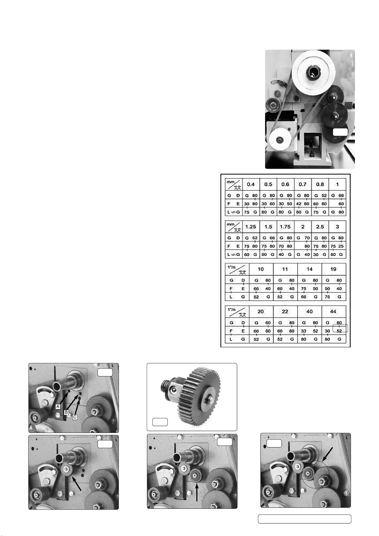
5.9. SCREW CUTTING
5.9.1. Similar to turning with auto feed except that the feed rate is very much faster, demanding
increased care from the operator.
5.9.2. Select the required leadscrew gear train from the charts (fig. 3).
5.9.3. Open the headstock end cover (fig. 1.21).
5.9.4. Remove the gear retaining circlips and nut (fig. 2) and slacken the belt tensioner.
5.9.5. Replace the existing gears with those required, in the positions shown in fig. 8.
5.9.6. Adjust gears B and C, so that the train meshes with minimum backlash but without being tight.
5.9.7. Tighten adjuster screw (fig. 6.4) and refit the end cover. DO NOT operate the lathe with the end
cover open.
5.9.8. Mount the workpiece in the lathe with the left hand end of the intended thread as far from the
chuck as possible.
5.9.9. With the tool positioned for the first cut, ensure that the automatic feed is engaged (fig.1.12) and
that the leadscrew lever (fig. 1.18) is set to FWD or REV as required for the thread.
5.9.10. Ensure that the cross slide lock (fig. 1.8) is not applied.
5.9.11. Switch on the lathe.
5.9.12. When the tool reaches the end of the thread switch off the lathe. DO NOT disengage the
leadscrew.
5.9.13. Reposition the tool for the second cut by moving the forward/reverse
switch (fig.1.18) to reverse and starting the lathe. When the tool
clears the start of the thread switch off the lathe.
5.9.14. Adjust the tool for the second cut and move the forward/reverse switch to
forward.
5.9.15. Start the lathe for the second cut. Repeat as necessary to complete the
thread cutting.
5.10. REVERSE THREADING
5.10.1. The Lathe can be setup to turn left-handed threads by adding another
fixed-shaft gear and moving the original fixed-shaft gear to another
mounting location.
5.10.2. Figure 2 shows the three mounting locations for fixed-shaft gears
(spindle drive pulley is removed for clarity). For illustration purposes
see mounting positions A, B & C in fig.4.
5.10.3. To set up the gears for reverse threading:
5.10.3.1. Disconnect the lathe from the power source.
5.10.3.2. Locate the extra fixed-shaft gear (shown in fig. 5)
5.10.3.3. Thread the extra fixed-shaft gear into mounting location as shown fig.6.
5.10.3.4. When the machine is shipped, a fixed-shaft gear is in position C.
5.10.3.5. Remove that fixed-shaft gear from mounting location “C” and thread
it into mounting location “B” as shown in fig.7.
5.10.3.6. Loosen the cap screw on the gear bracket, and pivot the
bracket so the top gear meshes with the fixed-shaft gear
that is in position “B,” as shown in fig.4
5.10.3.7. Tighten the cap screw in the gear bracket to keep it from pivoting.
Spin the lathe chuck by hand to ensure that the gears do not bind.
5.10.3.8. Replace the cover and test run the machine before proceeding
with your specific operation.
Fig.3
Fig.4
Fig.5
Fig.6
Fig.8
Fig.7
Fig.2
Original Language Version
© Jack Sealey Limited
SM27.V3 Issue 1 9/12/24

6. MAINTENANCE
WARNING! Ensure that the lathe is unplugged from the power supply before attempting any maintenance.
NOTE: For lubricating your machine, we recommend that you use a manual oiler (oil can) filled with ISO 68 or SAE 20W non-detergent oil
or similar lubricant.
NOTE: Fault repair to be carried out only by skilled or instructed persons. Return to original supplier if required and only use genuine
parts for any replacements.
6.1. Before each use perform functional testing to confirm safe and expected operation.
6.1.1. Lubricate the leadscrew bearings (oil point to left of scale at handle end and oil point behind gear D at driven end).
6.1.2. Lubricate the leadscrew thread and the leadscrew gears.
6.1.3. Lubricate the cross slide (oil point behind scale and two on front face of slide).
6.1.4. Lubricate the compound slide (two oil points on top face).
6.1.5. Lubricate the tailstock (two oil points on top face).
6.1.6. Clean the machine after each use and oil all machined surfaces.
6.1.7. If any play becomes apparent in the slides adjust as follows:
6.1.8. a) Loosen the lock nuts (compound slide only) of the gib strip adjusting screws.
6.1.9. Those for the cross slide are on the right-hand side of the slide, and those for the tail stock are either side of the locking lever).
b)Lightly tighten the screws equally and check that the slide will not move with normal effort on the handle.
c)Back-off each screw by 1/4 turn (tighten the lock nuts, compound slide only).
d)Check that there is no play and that the slide moves smoothly.
e)If further adjustment is required, tighten or loosen the screws as necessary by 1/8th of a turn only and recheck.
6.1.10. Restrict availability of keys or tools to skilled or instructed persons only.
7. END OF LIFE
7.1. Refer to footer “ENVIRONMENT PROTECTION” and local / national regulations with reference to waste processing before `
disposing of lathe.
Sealey Group, Kempson Way, Suffolk Business Park, Bury St Edmunds, Suffolk. IP32 7AR
01284 757500 sales@sealey.co.uk www.sealey.co.uk
ENVIRONMENT PROTECTION
Recycle unwanted materials instead of disposing of them as waste. All tools, accessories and packaging should be sorted,
taken to a recycling centre and disposed of in a manner which is compatible with the environment. When the product
becomes completely unserviceable and requires disposal, drain any fluids (if applicable) into approved containers and
dispose of the product and fluids according to local regulations.
Note: It is our policy to continually improve products and as such we reserve the right to alter data, specifications and component parts without prior
notice. Please note that other versions of this product are available. If you require documentation for alternative versions, please email or call
our technical team on technical@sealey.co.uk or 01284 757505.
Important: No Liability is accepted for incorrect use of this product.
Warranty: Guarantee is 12 months from purchase date, proof of which is required for any claim.
REGISTER YOUR
PURCHASE HERE
Original Language Version
© Jack Sealey Limited
SM27.V3 Issue 1 9/12/24
Parts support is available for this product. Please email sales@sealey.co.uk or telephone 01284 757500