Loading ...
Loading ...
Loading ...
Chapter 6 MATH and Measurements RIGOL
MSO2000A/DS2000A User’s Guide 6-15
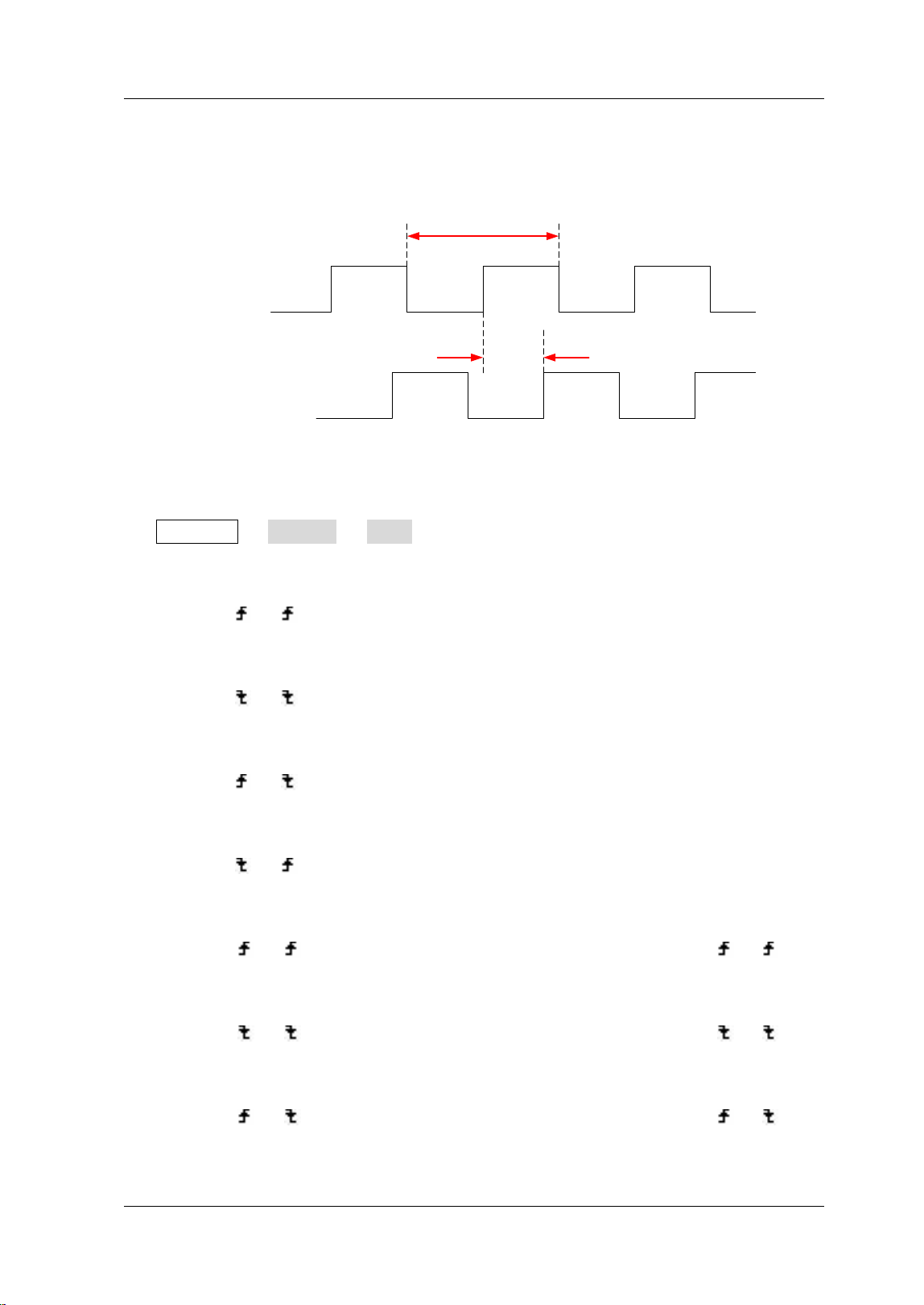
Delay and Phase
Source 1
Source 2
Period
Delay
Figure 6-4 Delay and Phase
Source 1 and Source 2 can be CH1, CH2 or any channel of D0-D15. You can set them
via Measure Setting Type ”Delay” (“Phase”). For the setting method,
please refer to the detailed introduction in “Measurement Setting”.
1. Delay 1
→2 : the time difference between the rising edges of source 1 and
source 2. Negative delay indicates that the selected rising edge of source 1
occurred after the selected rising edge of source 2.
2. Delay 1
→2 : the time difference between the falling edges of source 1 and
source 2. Negative delay indicates that the selected falling edge of source 1
occurred after the selected falling edge of source 2.
3. Delay 1
→2 : the time difference between the rising edge of source 1 and
the falling edge of source 2. Negative delay indicates that the selected rising
edge of source 1 occurred after the selected falling edge of source 2.
4. Delay 1
→2 : the time difference between the falling edge of source 1 and
the rising edge of source 2. Negative delay indicates that the selected falling
edge of source 1 occurred after the selected rising edge of source 2.
5. Phase 1
→2 : phase difference calculated according to “Delay 1 →2 ” and
the period of source 1, expressed in degree. The calculation formula is as shown
below.
6. Phase 1
→2 : phase difference calculated according to “Delay 1 →2 ” and
the period of source 1, expressed in degree. The calculation formula is as shown
below.
7. Phase 1
→2 : phase difference calculated according to “Delay 1 →2 ” and
the period of source 1, expressed in degree. The calculation formula is as shown
Loading ...
Loading ...
Loading ...