Loading ...
Installation
Terminal
Device
low voltage conduit with inner
diameter larger than 25 mm.
Stand Pole
Choose flat ground for installation. Cement foundation is
recommended for outdoor scenarios.
The suggested inner diameter of the low voltage conduit is
larger than 25 mm.
The installation steps of stand poles with exit button,
card reader and QR code scanner are the same.
The cable length of stand pole with exit button is 2.3 m in
total including reserved length of 1 m. The cable length of
stand pole with card reader, QR code scanner and card
receiver is 4.5 m in total including reserved length of 3 m.
The dimension of cable hole is 35 mm × 30 mm.
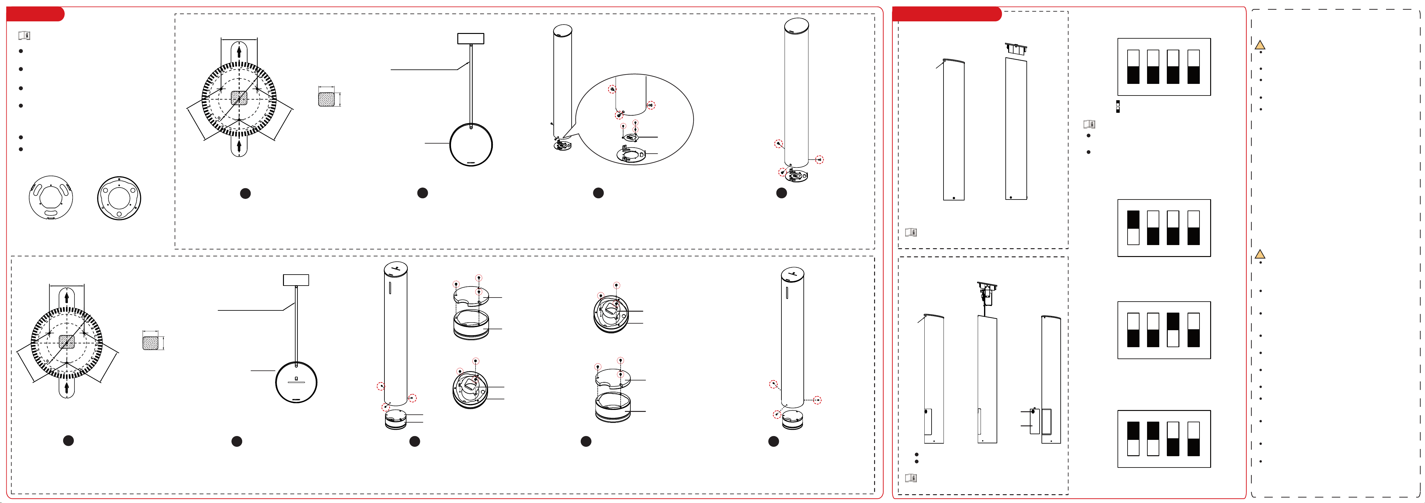
Drill Holes
Installation Sticker
Cable Hole
Bury Low Voltage Conduit
Fix Base
Fix Stand Pole
1
2 3 4
Attatch the installation sticker to the ground as the arrow indicates. Drill 3
holes at the position of black points and place 3 expansion bolts of M8×80.
1
Bury low voltage conduit between the stand pole and terminal
devices. The suggested inner diameter of the low voltage
conduit is larger than 25 mm.
Fix the stand pole to the base with the 3 removed screws of M6 in step 3a.
a. Loosen and remove the 3 screws of M6 at the bottom to disassemble the stand pole.
b. Loosen the 3 screws of M3 on the metal sheet to remove the base.
c. Place the base on the ground according to the holes on the base and expansion
bolts. Fix the base with 3 screws.
d. Put cables through the cable hole of the base and buried conduit. Fix the metal
sheet back to the base with the 3 removed screws of M3 in step b.
Stand Pole with Peripherals
Stand Pole with Card Receiver
Terminal
Device
low voltage conduit with inner
diameter larger than 25 mm.
Stand Pole
Bury Low Voltage Conduit
Bury low voltage conduit between the stand pole and
turnstile. The suggested inner diameter of the low voltage
conduit is larger than 25 mm.
Disassemble Stand Pole
Fix Base
Fix Stand Pole
2 3 4 5
a. Remove the 3 screws of M6 at the bottom of the stand pole.
b. Remove the 3 screws of M3 in the base cover.
c. Remove the 3 acrews of M3 on the metal sheet.
a. Place the base on the ground according to the holes on the base and expansion
bolts. Fix the base with 3 screws.
b. Put cables through the cable hole of the base and buried conduit. Fix the metal
sheet back to the base with the 3 removed screws of M3 in step b..
c. Adjust the position of the base cover and make sure the arc opening face the
entrance direction. Fix the cover to the base with 3 removed screws of M3in step 3b.
Adjust the stand pole to the proper direction and fix the stand pole
to the base with the 3 removed screws of M6 in step 3a.
M6 Screws
M3 Screws
Metal Sheet
Base
Installation Sticker
a
b
b
c
c
M6 Screws
Base Cover
Base Cover
Base
Base
Base
Base
Base
Base Cover
Metal Sheet
Metal Sheet
M6 Screws
M3 Screws
M3 Screws
M3 Screws
M3 Screws
Maintenance and Configuration
Screw
Remove the top screw, turn the cap clockwise
and lift the cap.
Lift the cap slowly in order not to cause damage to
cables or other device parts.
Lift the cap slowly in order not to cause damage to cables or
other device parts.
Stand Pole with Peripherals
Card Reader Configuration
Stand Pole with Card Receiver
Screw
Remove the top screw, turn the cap clockwise and lift the cap.
Put the key into the door lock and turn the key clockwise to
open the maintenance door.
Lock
Maintenance
Door
The default DIP switch set of card readers on the stand pole with
card reader and card receiver is shown as follows.
You can change the DIP switch set at your actual needs before
installation.
:DIP switch is set to the ON side (ON)
:DIP switch is set to the OFF side (OFF)
ON
1 2 3 4
ON
ON
ON
1
1
1
2
2
2
3
3
3
4
4
4
Card Reader DIP Switch (Entrance)
Card Reader DIP Switch (Exit)
Card Reader DIP Switch
(Stand Pole with Card Receiver)
The stand pole with peripheral is designed with 3 bean-
shaped holes on the base for expansion screws. The stand
pole with card receiver is designed with 3 circular holes
on the base for expansion screws.
Base of Stand Pole
with Peripherals
Base of Stand Pole
with Card Receiver
76 mm
35 mm
30 mm
76 mm
76 mm
88 mm
Cable Hole
M6 Screws
Drill Holes
Attatch the installation sticker to the ground as the arrow indicates. Drill 3
holes at the position of black points and place 3 expansion bolts of M8×80.
Warning
In the use of the product, you must be in strict compliance
with the electrical safety regulations of the nation and
region.
Do not connect several devices to one power adapter as
adapter overload may cause over-heat or fire hazard.
If smoke, odors or noise rise from the device, turn off the
power at once and unplug the power cable, and then
please contact the service center.
The socket-outlet shall be installed near the equipment
and shall be easily accessible.
1. Do not ingest battery. Chemical burn hazard!
2. This product contains a coin/button cell battery. If the
coin/button cell battery is swallowed, it can cause severe
internal burns in just 2 hours and can lead to death.
3. Keep new and used batteries away from children.
4. If the battery compartment does not close securely,
stop using the product and keep it away from children.
5. If you think batteries might have been swallowed or
placed inside any part of the body, seek immediate
medical attention.
6. CAUTION: Risk of explosion if the battery is replaced by
an incorrect type.
7. Improper replacement of the battery with an incorrect
type may defeat a safeguard (for example, in the case of
some lithium battery types).
8. Do not dispose of the battery into fire or a hot oven, or
mechanically crush or cut the battery, which may result in
an explosion.
9. Do not leave the battery in an extremely high
temperature surrounding environment, which may result
in an explosion or the leakage of flammable liquid or gas.
10. Do not subject the battery to extremely low air
pressure, which may result in an explosion or the leakage
of flammable liquid or gas.
11. Dispose of used batteries according to the instructions
Caution
Do not drop the device or subject it to physical shock, and
do not expose it to high electromagnetism radiation. Avoid
the equipment installation on vibrations surface or places
subject to shock (ignorance can cause equipment
damage).
Do not place the device in extremely hot (refer to the
specification of the device for the detailed operating
temperature), cold, dusty or damp locations, and do not
expose it to high electromagnetic radiation.
Exposing the equipment to direct sun light, low ventilation
or heat source such as heater or radiator is forbidden
(ignorance can cause fire danger). The device cover for
indoor use shall be kept from rain and moisture.
Exposing the equipment to direct sun light, low ventilation
or heat source such as heater or radiator is forbidden
(ignorance can cause fire danger).
Please use a soft and dry cloth when clean inside and
outside surfaces of the device cover, do not use alkaline
detergents.
Biometric recognition products are not 100% applicable to
anti-spoofing environments. If you require a higher
security level, use multiple authentication modes.
The serial port of the equipment is used for debugging
only.
Wall Mounting: Install the equipment according to the
instructions in this manual. To prevent injury, this
equipment must be securely attached to the floor/wall in
accordance with the installation instructions.
Improper use or replacement of the battery may result in
hazard of explosion. Replace with the same or equivalent
type only. Dispose of used batteries according to the
instructions provided by the battery manufacturer.
This bracket is intended for use only with equipped
devices. Use with other equipment may result in instability
causing injury.
This equipment is for use only with equipped bracket. Use
with other (carts, stands, or carriers) may result in
instability causing injury.
!
!
Safety Instructions
80 mm
35 mm
30 mm
80 mm
80 mm
92 mm