TRUE RESIDENTIAL
®
15 INCH AND 24 INCH UNDERCOUNTER
INSTALL GUIDE AND USER'S MANUAL
“ B ” R E V I S I O N S
PRESERVE THE MOMENT
®

THANK YOU
FOR YOUR PURCHASE

1
15 INCH & 24 INCH INSTALL GUIDE
OWNERSHIP 4
SAFETY PRECAUTIONS 4
DISPOSAL OF OLD REFRIGERATOR 4
CFC DISPOSAL 4
UNCRATING 5
ELECTRICAL SPECIFICATIONS 6
OUTDOOR USE 6
INSTALLATION SPECIFICATIONS FOR STAINLESS SOLID AND GLASS DOOR 7-12
INSTALLATION SPECIFICATIONS FOR SOLID PANEL READY (OP), GL AS S
FRAMED PANEL READY (OG) AND INTEGRATED PANEL 13-29
INSTALLATION SPECIFICATIONS FOR BEVERAGE DISPENSER UNITS 30-38
INSTALLATION CHECKLIST 2
STAINLESS STEEL CARE AND CLEANING 72
GENERAL MAINTENANCE 73
CONDENSATION 73
SERVICE INFORMATION 73
FAQS 74-76
WARRANTY 77
TRUE PRECISION CONTROL
®
OPERATION AND CABINET COMPONENTS (ALL MODELS) 44-59
HOME ALARM SYSTEM - (DUAL ZONE WINE CABINET ONLY) 60-61
SHELVING ADJUSTMENT 62-63
STACKING KIT INSTRUCTIONS 64-70
INSTALLING TOE KICK 38
LEVELING REFRIGERATOR 38
INSTALLING ANTI-TIP BRACKETS 39-40
INSTALLING THE DOOR STOP 41-42
TABLE OF CONTENTS

2
TRUE RESIDENTIAL
®
INSTALLATION CHECKLIST
To ensure a proper installation, this checklist should be completed to ensure that no part of the
process has been overlooked.
Have all packaging materials been removed?
Have the anti-tip brackets been installed securely and are they properly engaging the unit?
Is the unit leveled properly with all leveling legs making contact with the floor? Has the toe kick
been installed?
Has door stop been installed (if needed)?
Are panels attached securely and properly aligned? (Overlay cabinets only).
Does the customer understand the unit’s operation?
Has the customer been given the key and literature package?
Have stainless steel surfaces been inspected for any imperfections? This is to be done by the
authorized True dealer or installer with the customer, upon completion of installation. Stainless
steel doors, handles and shelves are covered by a limited 30-day warranty for cosmetic defects.
Is the unit operating properly? If not, is the unit plugged in? Is the control turned on?

3
15 INCH & 24 INCH INSTALL GUIDE
O w n e r s h i p
s a f e t y p r e c a u t i O n s
D i s p O s a l O f t h e O l D r e f r i g e r a t O r
c f c D i s p O s a l
u n c r a t i n g
e l e c t r i c a l s p e c i f i c a t i O n s
3 - 6
PRESERVE THE MOMENT
®
O u t D O O r u s e
i n s t a l l a t i O n s p e c i f i c a t i O n s
4
TRUE RESIDENTIAL
®
OWNERSHIP
To insure that your unit works properly from the
first day, it must be installed properly. (We highly
recommend a trained refrigeration mechanic and
electrician install your True Residential
®
Cabinet.) The
cost of a professional installation is money well spent.
Before you start to install your True Residential
®
Cabinet, carefully inspect it for freight damage.
If damage is discovered, immediately file a claim with
the delivery freight carrier. True is not responsible for
damage incurred during shipment.
Any questions about the installation please
contact your True dealer or True Technical Service
Department at 1-800-325-6152 (Please have your
model and serial numbers available when you call our
Service Department).
SAFETY PRECAUTIONS
• This refrigerator must be properly installed
and located in accordance with the installation
instructions before it is used.
• Do not allow children to climb, stand or hang on
the shelves in the refrigerator. They could damage
the refrigerator and seriously injure themselves.
• Do not store or use gasoline or other flammable
vapors and liquids in the vicinity of this or any
other appliance.
• Keep hands away from the “pinch point” areas
(gaps between the doors and between the doors
and cabinet) small areas are not necessarily safe.
• Unplug the refrigerator before cleaning and
making repairs.
NOTE: WE STRONGLY RECOMMEND THAT
ANY SERVICING BE PERFORMED BY A
QUALIFIED INDIVIDUAL.
• Setting temperature control to OFF only removes
power from the refrigeration system, it does not
remove power from other circuits. For example,
temperature control and lights.
PROPER DISPOSAL OF THE OLD
REFRIGERATOR
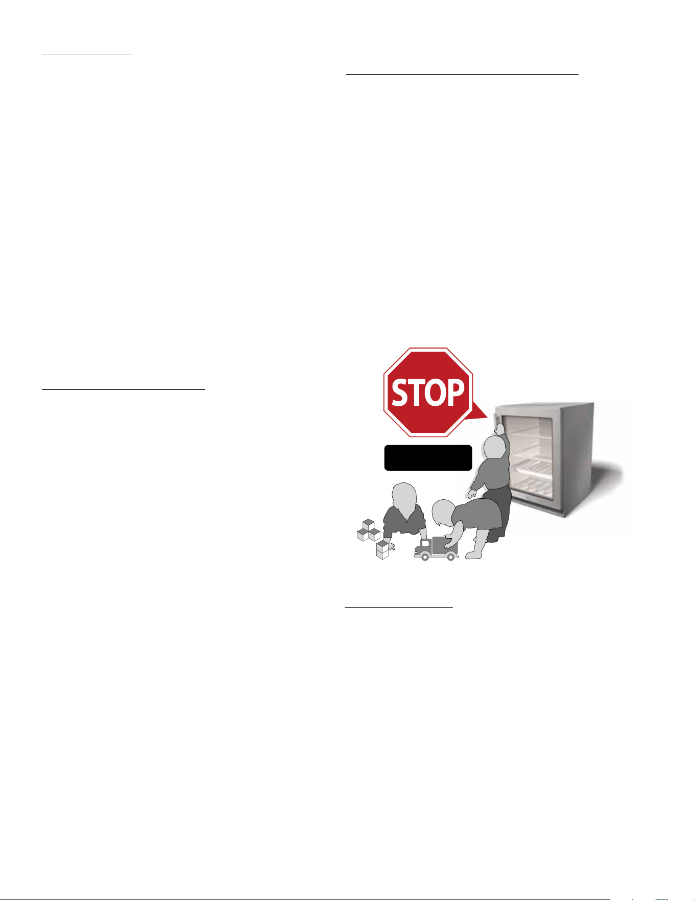
Child entrapment and suffocation are not problems
of the past. Junked or abandoned refrigerators are
still dangerous... Even if they will sit for “just a few
days”. If you are getting rid of your old refrigerator,
please follow the instructions below to help prevent
accidents.
BEFORE YOU THROW AWAY YOUR OLD REFRIGERATOR OR
FREEZER:
• Take off the doors.
• Leave the shelves in place so that children may
not easily climb inside.
CFC DISPOSAL
Your old refrigerator may have a cooling system that
used CFCs (chlorofluorocarbons). CFCs are believed
to harm stratospheric ozone. If you are throwing away
your old refrigerator, make sure the CFC refrigerant is
removed for proper disposal by a qualified service. If
you intentionally release this CFC refrigerant you can
be subject to fines and imprisonment under provisions
of the environment legislation.
DANGER!
RISK OF CHILDREN
ENTRAPMENT
5
15 INCH & 24 INCH INSTALL GUIDE
packing material
TOE KICK IS ATTACHED
TO BACK OF UNIT
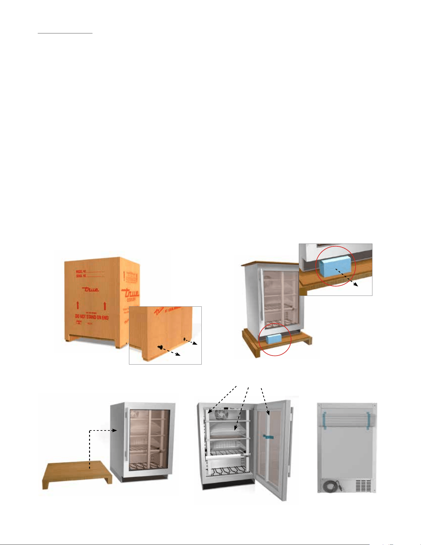
UNCRATING
Required Tools:
• Cutting utensil (utility knife)
• Hammer
• Crowbar
• Phillips head screwdriver
The following procedure is recommended for
uncrating the unit:
MOVE YOUR UNIT AS CLOSE TO THE FINAL
LOCATION AS POSSIBLE BEFORE REMOVING THE
WOODEN SKID.
A. Remove nails securing cardboard box to the
wooden skid. Then discard any outer packaging
(cardboard, clear plastic).
INSPECT FOR CONCEALED DAMAGE. AGAIN,
IMMEDIATELY FILE A CLAIM WITH THE FREIGHT
CARRIER IF THERE IS DAMAGE.
B. IMPORTANT: Cut green polyband and remove
styrofoam block before removing refrigerator from
pallet.
C. Remove skid by carefully lifting the refrigerator off
and place skid aside.
D. Open the unit and remove any packing material.
Styrofoam, tape, and any other material used
for shipping purposes.
NOTE: KEYS FOR UNIT ARE PROVIDED WITH
THIS PACKET.
NOTE: ANTI-TIP KIT AND DOOR STOP ARE PACKED
INSIDE UNIT.
A B
C D
6
TRUE RESIDENTIAL
®
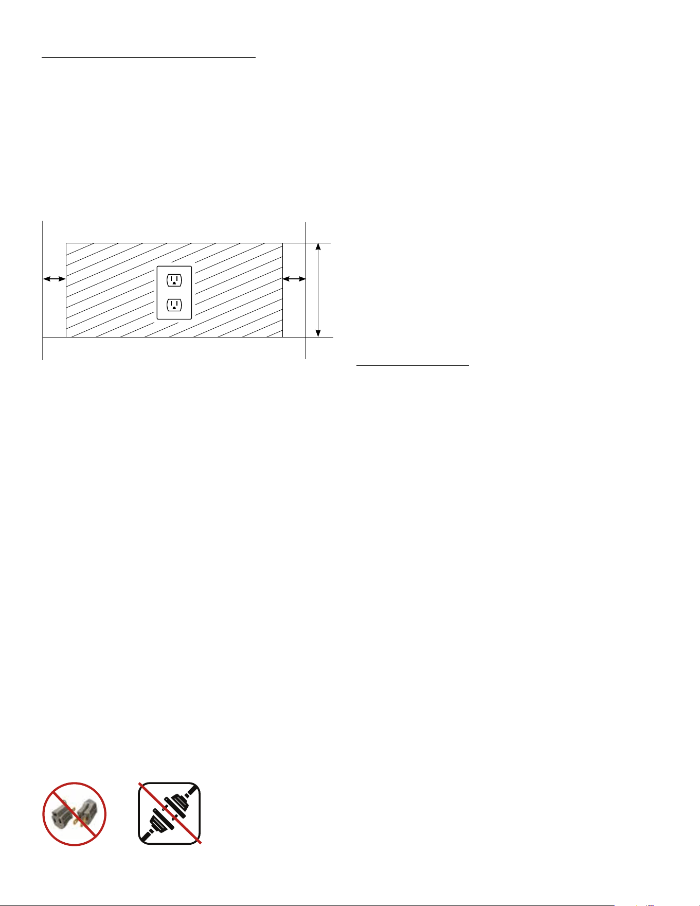
ELECTRICAL SPECIFICATIONS
Do not, under any circumstances, cut or remove
the third (ground) prong from the power cord. For
personal safety, this appliance must be properly
grounded.
To minimize the depth of the cutout opening, the
electrical outlet must be positioned as shown below.
Outlet must be flush with wall.
Before your new unit is connected to a power supply,
check the incoming voltage with a volt meter. If
anything less than 100% of the rated voltage for
operation is noted, correct immediately.
The power cord of this appliance is equipped with
a 3-prong (grounding) plug which mates with a
standard 3-prong (grounding) wall outlet to minimize
the possibility of electric shock hazard from this
appliance. A 115V AC, 60 Hz, 15 amp circuit
breaker and electrical supply are required.
Each unit requires a dedicated circuit. Have the wall
outlet and circuit checked by a qualified electrician
to make sure the outlet is properly grounded.
If the outlet is a standard 2-prong outlet, it is your
personal responsibility and obligation to have it
replaced with the properly grounded 3 prong wall
outlet.
Do not use an extension cord or two prong adaptor.
Electrical ground is required on this appliance.
The unit should always be plugged into its own
individual electrical circuit, which has a voltage rating
that matches the rating plate. This provides the best
performance and also prevents overloading house
wiring circuits which could cause a fire hazard from
overheated wires. Never unplug your refrigerator by
pulling on the power cord. Always grip plug firmly
and pull straight out from the outlet.
Repair or replace immediately all power cords that
have become frayed or otherwise damaged. Do not
use a cord that shows cracks or abrasion damage
along its length or at either end. When moving the
refrigerator away from the wall, be careful not to roll
over or damage the power cord.
OUTDOOR USE
All True undercounter units are UL-rated for outdoor
use.
In regions that have high dewpoint/high humidity, it
is possible that you will see some condensation on
the glass and possibly around some of the gasket
seals. For best operation, it is recommended that
your True unit be stocked full with product.
To winterize your True unit, it is recommended once
the temperature reaches below 32ºF consistently that
products are removed from the unit, the unit is either
unplugged or turned OFF, and a cover is placed over
the unit.
Installation – For best operation, it is recommended
that your True unit is installed so that the countertop
of your outdoor kitchen/bar covers the door or drawer
gasket. Cutout opening should be a minimum of 24
inches deep and unit should be installed “flush”.
Please note that door/drawer gaskets do not provide
a water tight seal against the elements.
2" 2"
8"
Rear wall of cut out

7
15 INCH & 24 INCH INSTALL GUIDE
i n s t a l l a t i O n s p e c i f i c a t i O n s
f O r
s t a i n l e s s s O l i D ( s s )
a n D g l a s s D O O r ( s g )
7 - 12
PRESERVE THE MOMENT
®
8
TRUE RESIDENTIAL
®
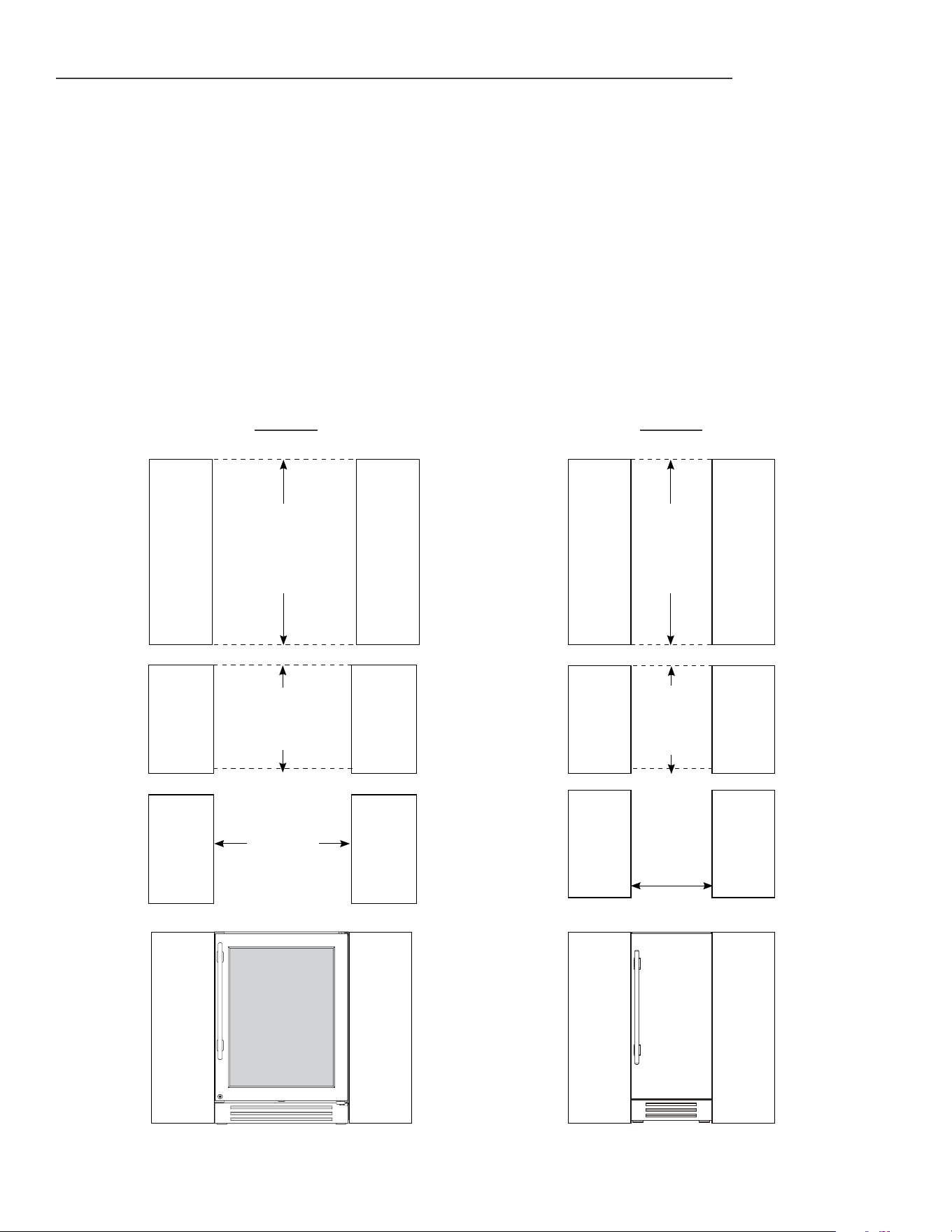
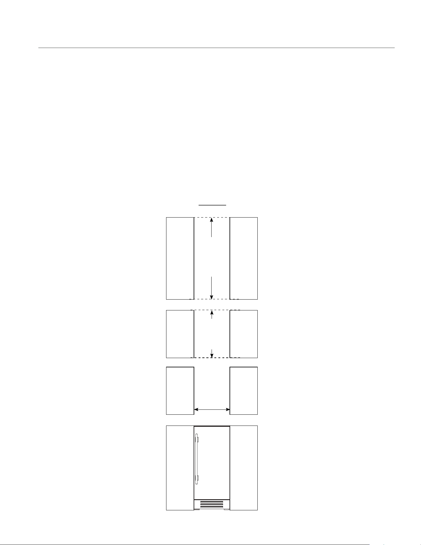
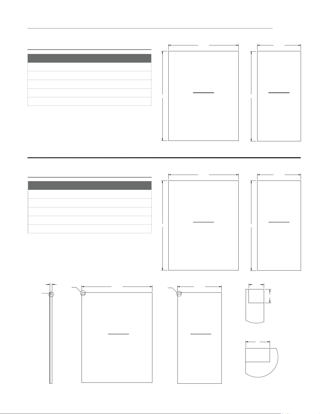
INSTALLATION SPECIFICATIONS - STAINLESS SOLID & GLASS DOOR
True’s Stainless Solid and Glass Door units are designed to be inserted into a cabinet opening or free standing.
Below are recommended dimensions for rough opening.
TRUE’S CABINETS ARE UL RATED FOR USE IN OUTDOOR SETTINGS.
IN OUTDOOR LOCATIONS WHERE THE AMBIENT TEMPERATURE REGULARLY EXCEEDS 95˚F, IT IS RECOMMENDED TO
VENT THE REAR OF THE CUT OUT OPENING IN THE AREA SHOWN BELOW FOR OPTIMUM PERFORMANCE.
THE RECOMMENDED CUT OUT SIZE IS 4" X 10".
WHEN INSTALLING TWO TRUE UNITS SIDE BY SIDE, IT IS RECOMMEND TO LEAVE A 5/8” GAP TO BETWEEN
CABINETS TO ENSURE MOISTURE DOES NOT DEVELOP ON AN INDOOR APPLICATION. FOAM PADS CAN BE
PURCHASED FROM OUR PARTS DEPARTMENT AT 844-849-6226 OR TRUERESIDENTIALPARTS@TRUEMFG.COM. IF
INSTALLING FOAM PADS WE RECOMMEND A PAD IS PUT ON EACH OF THE UNITS JOINED TOGETHER.
23
7
/
8
"
29
3
/
4
"
4
1
/
8
"
Rough Opening
HEIGHT
34
1/2
"
Front view
of unit
between
cabinets
Rough Opening
DEPTH
24"
Rough Opening
WIDTH
24"
24 INCH
Rough
Opening
HEIGHT
34
1/2
"
Rough
Opening
DEPTH
24"
Front
view of
unit
between
cabinets
Rough
Opening
WIDTH
15"
15 INCH
9
15 INCH & 24 INCH INSTALL GUIDE
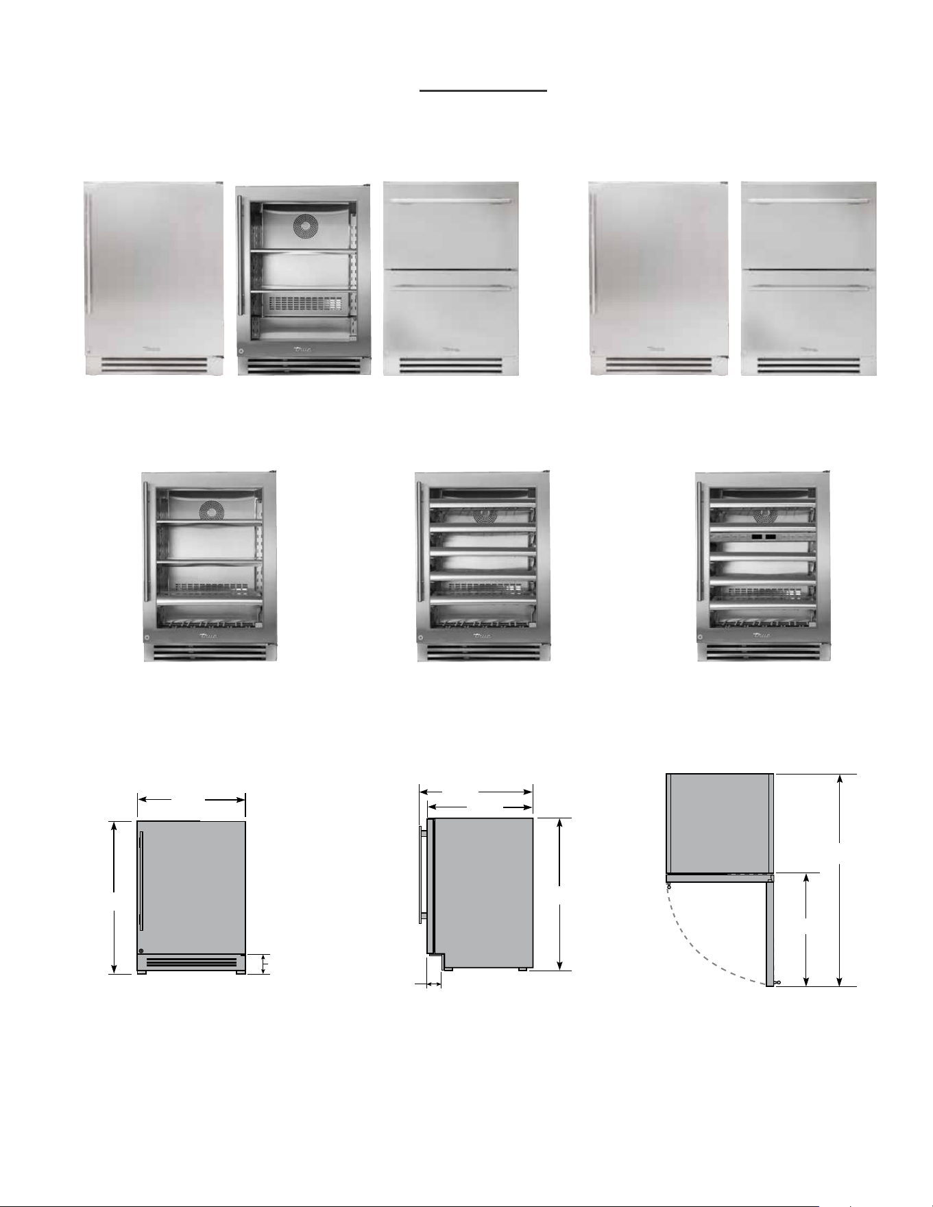
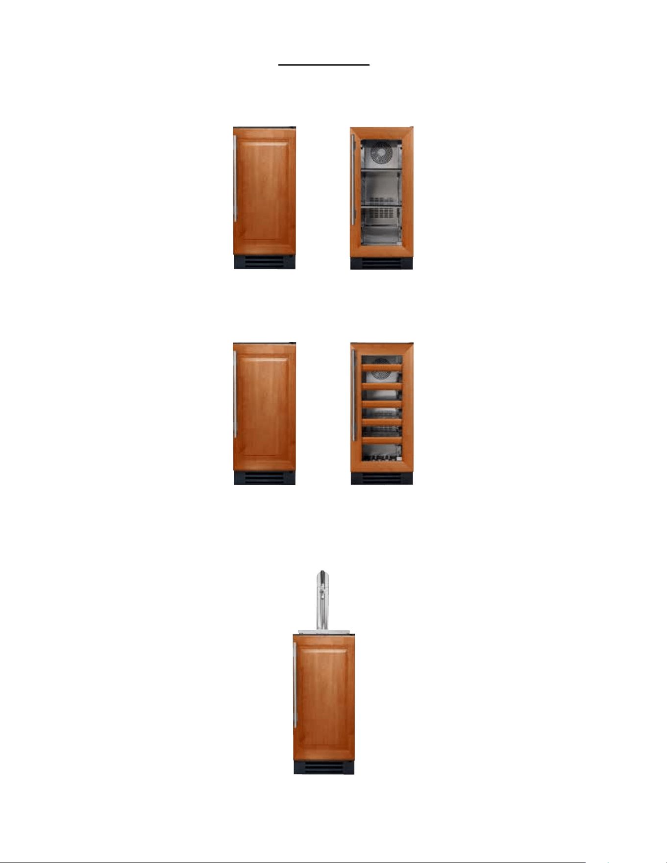
ALL REFRIGERATOR FREEZER
BEVERAGE CENTER WINE CABINET DUAL ZONE WINE CABINET
TUR-24-R/L-SS-B TUF-24-R/L-SS-BTUR-24-R/L-SG-B TUR-24D-SS-B TUF-24D-SS-B
TBC-24-R/L-SG-B TWC-24-R/L-SG-B TWC-24DZ-R/L-SG-B
DIMENSIONS MAY VARY BY ±
1
/
8
"
23
7
/8"
34
1
/4"
4
1
/8"
34
1
/4"
23
7
/8"
25
3
/4"
3
3
/4"
46
7
/8"
25
1
/4"
24 INCH
10
TRUE RESIDENTIAL
®
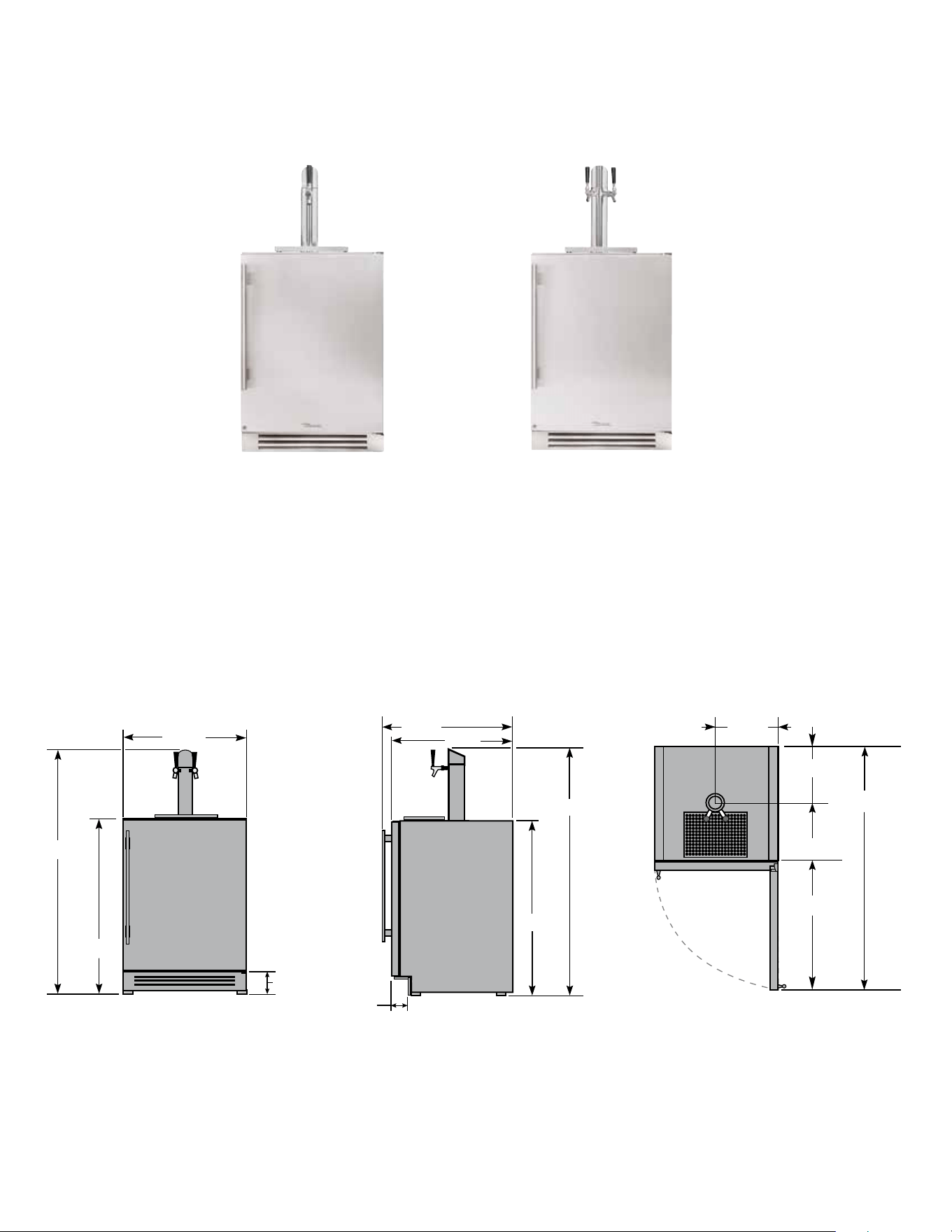
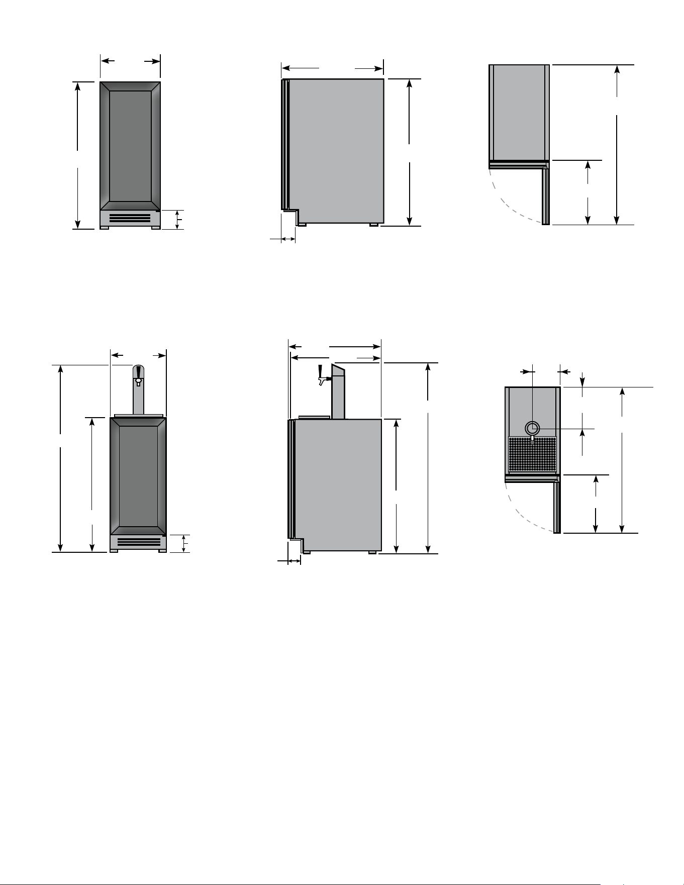
TUR-24BD-R/L-SS-B TUR-24DD-R/L-SS-B
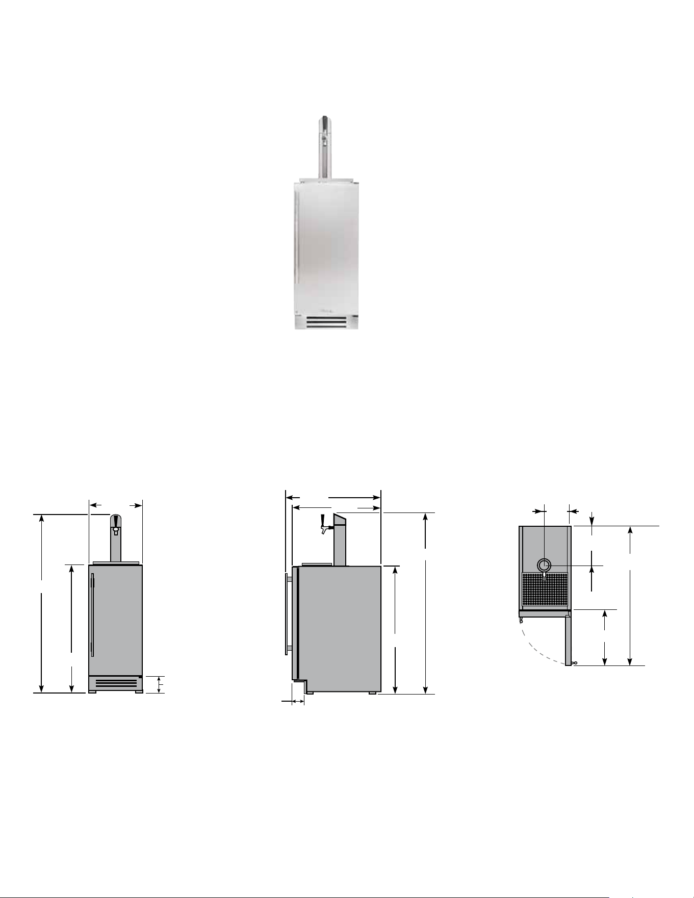
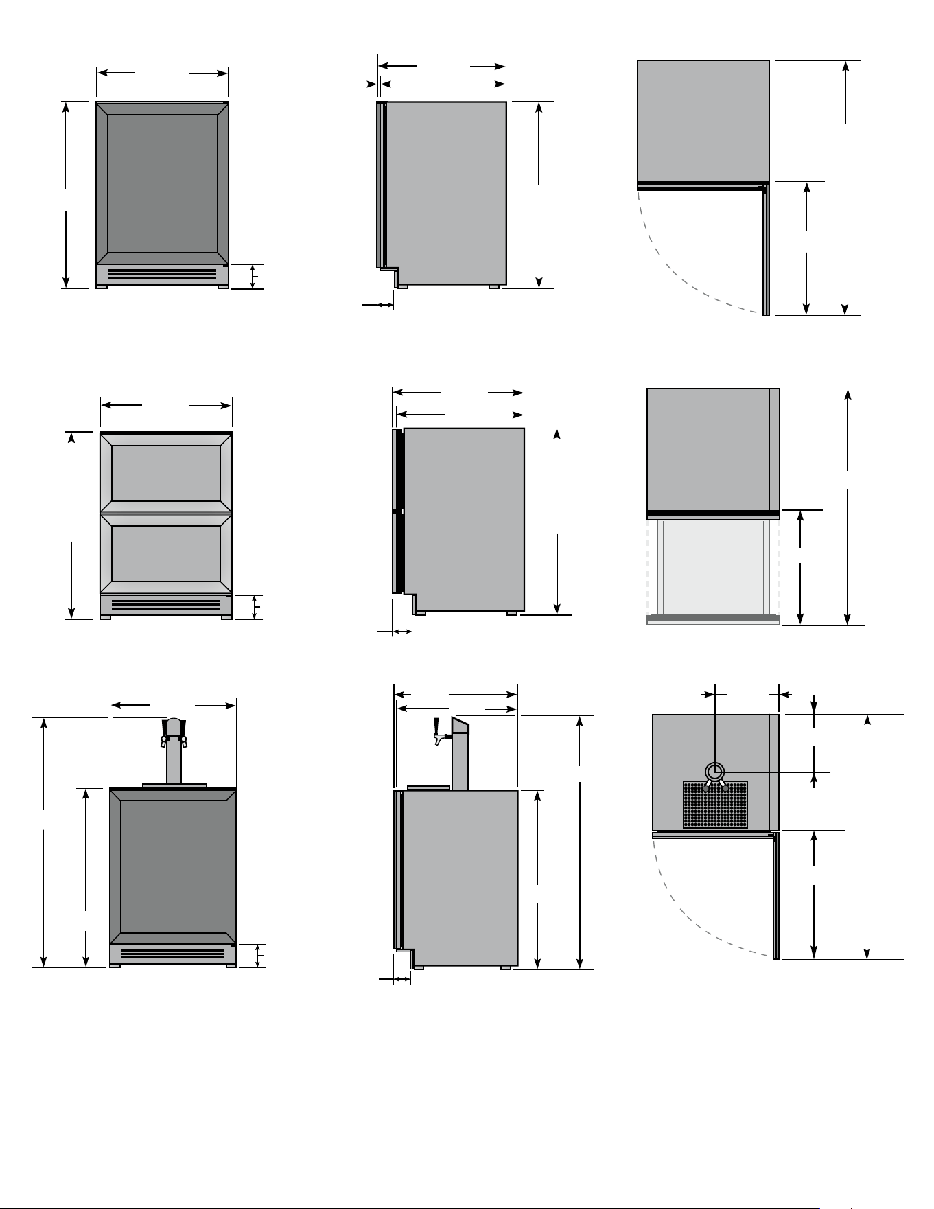
Be veR age Di Spe n SeR
DIMENSIONS MAY VARY BY ±
1
/
8
"
24" SINGLE TAP UNIT ACCOMMODATES (1) SHORT 1/4
BARREL, (1) SLIM 1/4 BARREL, OR (1) 1/6 BARREL.
24" DUAL TAP UNIT ACCOMMODATES (2) 1/6 BARRELS
OR (1) SLIM 1/4 BARREL AND (1) 1/6 BARREL.
23
7
/8"
34
1
/4"
46
7
/8"
11
7
/8"
10
1
/4"
25
1
/4"
4
1
/8"
34
1
/4"
23
7
/8"
25
3
/4"
3
3
/4"
50"
50"
11
15 INCH & 24 INCH INSTALL GUIDE
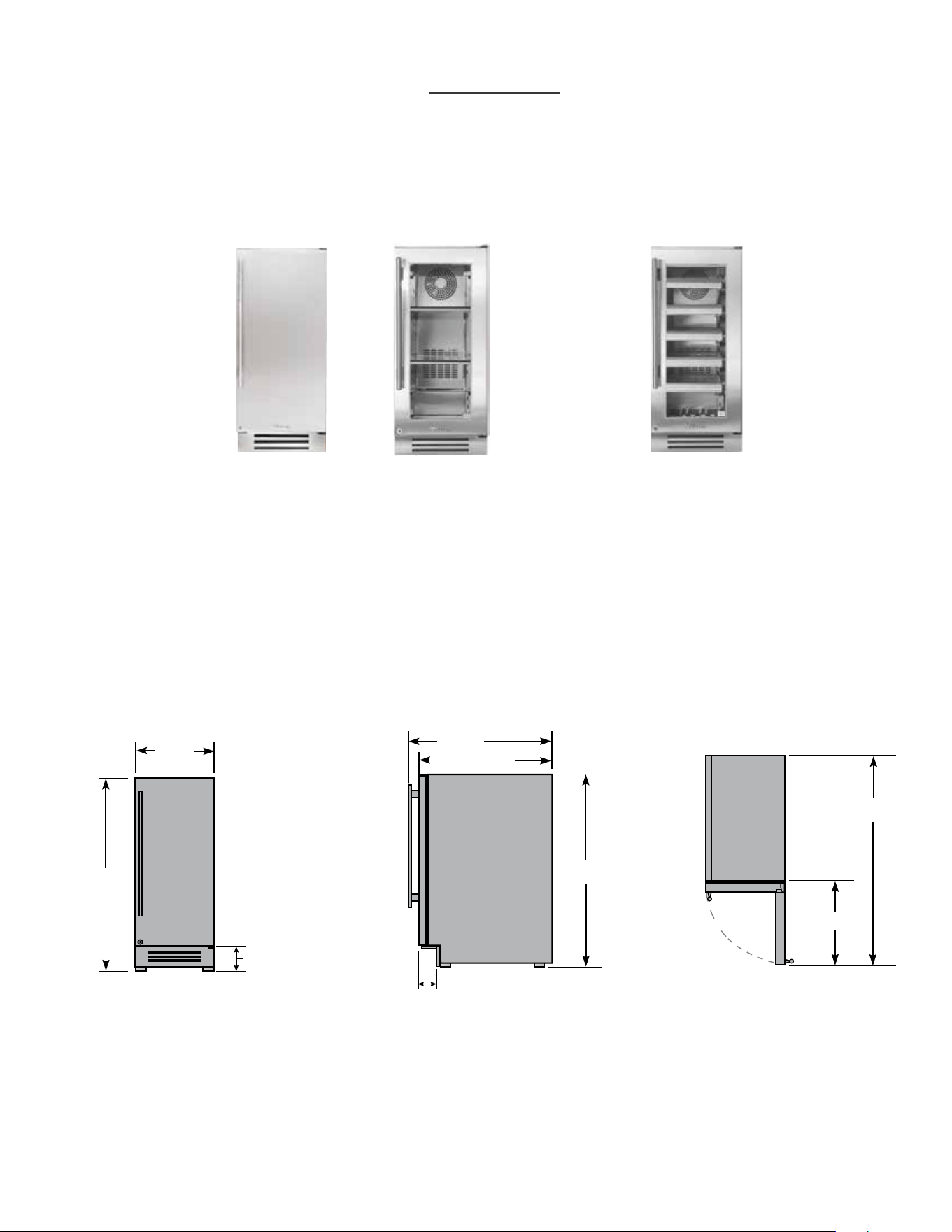
ALL REFRIGERATOR
DIMENSIONS MAY VARY BY ±
1
/
8
"
TUR-15-R/L-SS-B TUR-15-R/L-SG-B
WINE CABINET
TWC-15-R/L-SG-B
14
7
/8"
34
1
/4"
16
1
/4"
37
7
/8"
34
1
/4"
23
7
/8"
25
3
/4"
3
3
/4"
4
1
/8"
15 INCH
12
TRUE RESIDENTIAL
®
DIMENSIONS MAY VARY BY ±
1
/
8
"
TUR-15BD-R/L-SS-B
BEVERAGE DISPENSER
15" SINGLE TAP UNIT ACCOMMODATES (1) SLIM 1/4
BARREL OR (1) 1/6 BARREL.
16
1
/4"
37
7
/8"
14
7
/8"
34
1
/4"
7
1
/2"
10
1
/4"
4
1
/8"
34
1
/4"
23
7
/8"
25
3
/4"
3
3
/4"
50"
50"

13
15 INCH & 24 INCH INSTALL GUIDE
13 - 27
i n s t a l l a t i O n s p e c i f i c a t i O n s
f O r s O l i D p a n e l r e a D y ( O p ) a n D
g l a s s f r a m e D p a n e l r e a D y ( O g )
PRESERVE THE MOMENT
®
14
TRUE RESIDENTIAL
®
23
7
/
8
"
29
3
/
4
"
4
1
/
8
"
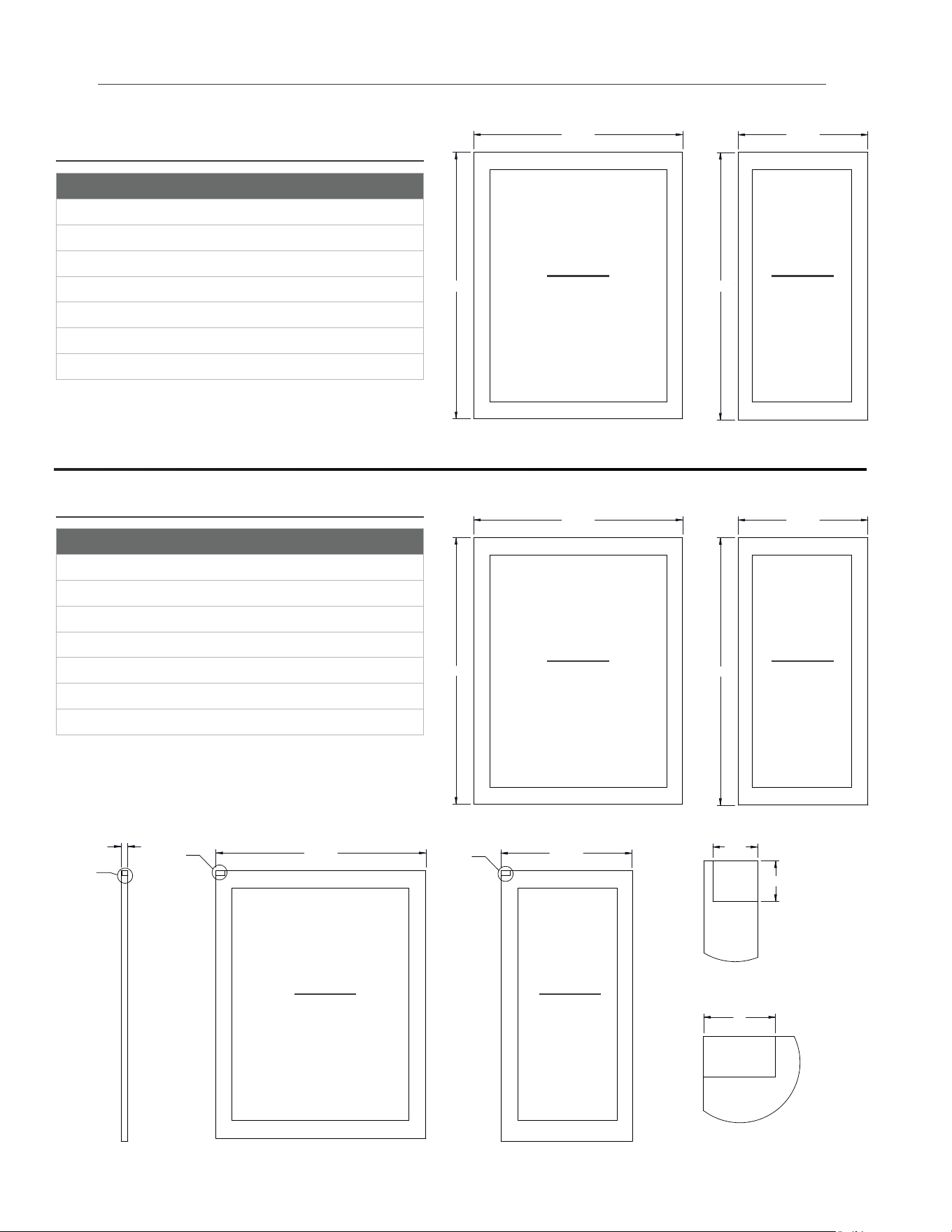
Rough Opening
HEIGHT
34
1/2
"
Front view
of unit
between
cabinets
Rough Opening
DEPTH
24"
Rough Opening
WIDTH
24"
24 INCH
24 INCH INSTALLATION SPECIFICATIONS -
SOLID (OP) AND GLASS FRAMED PANEL (OG)
True’s 24 inch units with Solid and Glass Framed Panels are designed to be inserted into a cabinet opening
or free standing. Below are recommended dimensions for rough opening.
TRUE’S CABINETS ARE UL RATED FOR USE IN OUTDOOR SETTINGS.
IN OUTDOOR LOCATIONS WHERE THE AMBIENT TEMPERATURE REGULARLY EXCEEDS 95˚F, IT IS RECOMMENDED
TO VENT THE REAR OF THE CUT OUT OPENING IN THE AREA SHOWN BELOW FOR OPTIMUM PERFORMANCE.
THE RECOMMENDED CUT OUT SIZE IS 4" X 10".
WHEN INSTALLING TWO TRUE UNITS SIDE BY SIDE, IT IS RECOMMEND TO LEAVE A 5/8” GAP TO BETWEEN
CABINETS TO ENSURE MOISTURE DOES NOT DEVELOP ON AN INDOOR APPLICATION. FOAM PADS CAN BE
PURCHASED FROM OUR PARTS DEPARTMENT AT 844-849-6226 OR TRUERESIDENTIALPARTS@TRUEMFG.COM.
IF INSTALLING FOAM PADS WE RECOMMEND A PAD IS PUT ON EACH OF THE UNITS JOINED TOGETHER.
15
15 INCH & 24 INCH INSTALL GUIDE
TWC-24DZ-R/L-OG-B
TBC-24-R/L-OP-B
24 INCH
ALL REFRIGERATOR FREEZER
BEVERAGE CENTER
TBC-24-R/L-OG-B
WINE CABINET
TWC-24-R/L-OP-B TWC-24-R/L-OG-B
DUAL ZONE WINE CABINET
TWC-24DZ-R/L-OP-B
TUR-24-R/L-OG-BTUR-24-R/L-OP-B TUF-24-R/L-OP-BTUR-24D-OP-B TUF-24D-OP-B
TUR-24BD-R/L-OP-B TUR-24DD-R/L-OP-B
BEVERAGE DISPENSER
16
TRUE RESIDENTIAL
®
24" SINGLE TAP UNIT ACCOMMODATES (1) SHORT 1/4 BARREL, (1) SLIM
1/4 BARREL, OR (1) 1/6 BARREL. 24" DUAL TAP UNIT ACCOMMODATES
(2) 1/6 BARRELS OR (1) SLIM 1/4 BARREL AND (1) 1/6 BARREL.
*
INCLUDING 3/4" THICK PANEL (PROVIDED BY OTHERS)
DIMENSIONS MAY VARY BY ±
1
/
8
"
23
7
/8"
34
1
/4"
21"
42
5
/8"
34
1
/4"
23
1
/8"
23
7
/8"
3
3
/4"
4
1
/8"
23
7
/8"
34
1
/4"
25
1
/4"
46
7
/8"
34
1
/4"
23
7
/8"
3
3
/4"
4
1
/8"
23
1
/8"
3
/4"
23
7
/8"
34
1
/4"
46
7
/8"
11
7
/8"
10
1
/4"
25
1
/4"
4
1
/8"
34
1
/4"
23
1
/8"
23
7
/8"
3
3
/4"
50"
50"
17
15 INCH & 24 INCH INSTALL GUIDE
23
7
/8"
34
1
/4"
21"
42
5
/8"
34
1
/4"
23
1
/8"
23
7
/8"
3
3
/4"
4
1
/8"
15 INCH INSTALLATION SPECIFICATIONS -
SOLID (OP) AND GLASS FRAMED PANEL (OG)
True’s 15 inch units with Solid and Glass Framed Panels are designed to be inserted into a cabinet opening
or free standing. Below are recommended dimensions for rough opening.
TRUE’S CABINETS ARE UL RATED FOR USE IN OUTDOOR SETTINGS.
IN OUTDOOR LOCATIONS WHERE THE AMBIENT TEMPERATURE REGULARLY EXCEEDS 95˚F, IT IS RECOMMENDED
TO VENT THE REAR OF THE CUT OUT OPENING IN THE AREA SHOWN BELOW FOR OPTIMUM PERFORMANCE.
THE RECOMMENDED CUT OUT SIZE IS 4" X 10".
WHEN INSTALLING TWO TRUE UNITS SIDE BY SIDE, IT IS RECOMMEND TO LEAVE A 5/8” GAP TO BETWEEN
CABINETS TO ENSURE MOISTURE DOES NOT DEVELOP ON AN INDOOR APPLICATION. FOAM PADS CAN BE
PURCHASED FROM OUR PARTS DEPARTMENT AT 844-849-6226 OR TRUERESIDENTIALPARTS@TRUEMFG.COM.
IF INSTALLING FOAM PADS WE RECOMMEND A PAD IS PUT ON EACH OF THE UNITS JOINED TOGETHER.
Rough
Opening
HEIGHT
34
1/2
"
Rough
Opening
DEPTH
24"
Front
view of
unit
between
cabinets
Rough
Opening
WIDTH
15"
15 INCH
18
TRUE RESIDENTIAL
®
ALL REFRIGERATOR
TUR-15-R/L-OP-B TUR-15-R/L-OG-B
WINE CABINET
TWC-15-R/L-OP-B TWC-15-R/L-OG-B
BEVERAGE DISPENSER
TUR-15BD-R/L-OP-B
15 INCH
19
15 INCH & 24 INCH INSTALL GUIDE
14
7
/8"
34
1
/4"
16
1
/4"
37
7
/8"
34
1
/4"
23
7
/8"
3
3
/4"
4
1
/8"
15" SINGLE TAP UNIT ACCOMMODATES
(1) SLIM 1/4 BARREL OR (1) 1/6 BARREL.
*
INCLUDING 3/4" THICK PANEL (PROVIDED BY OTHERS)
DIMENSIONS MAY VARY BY ±
1
/
8
"
16
1
/4"
37
7
/8"
14
7
/8"
34
1
/4"
7
1
/2"
10
1
/4"
4
1
/8"
34
1
/4"
50"
3
3
/4"
50"
23
1
/8"
23
7
/8"
20
TRUE RESIDENTIAL
®
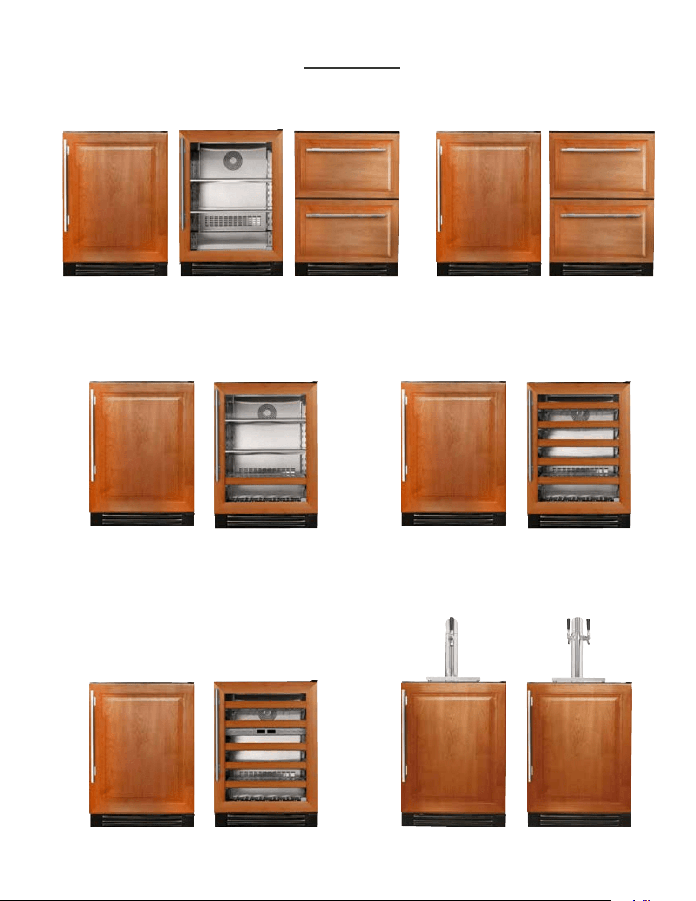
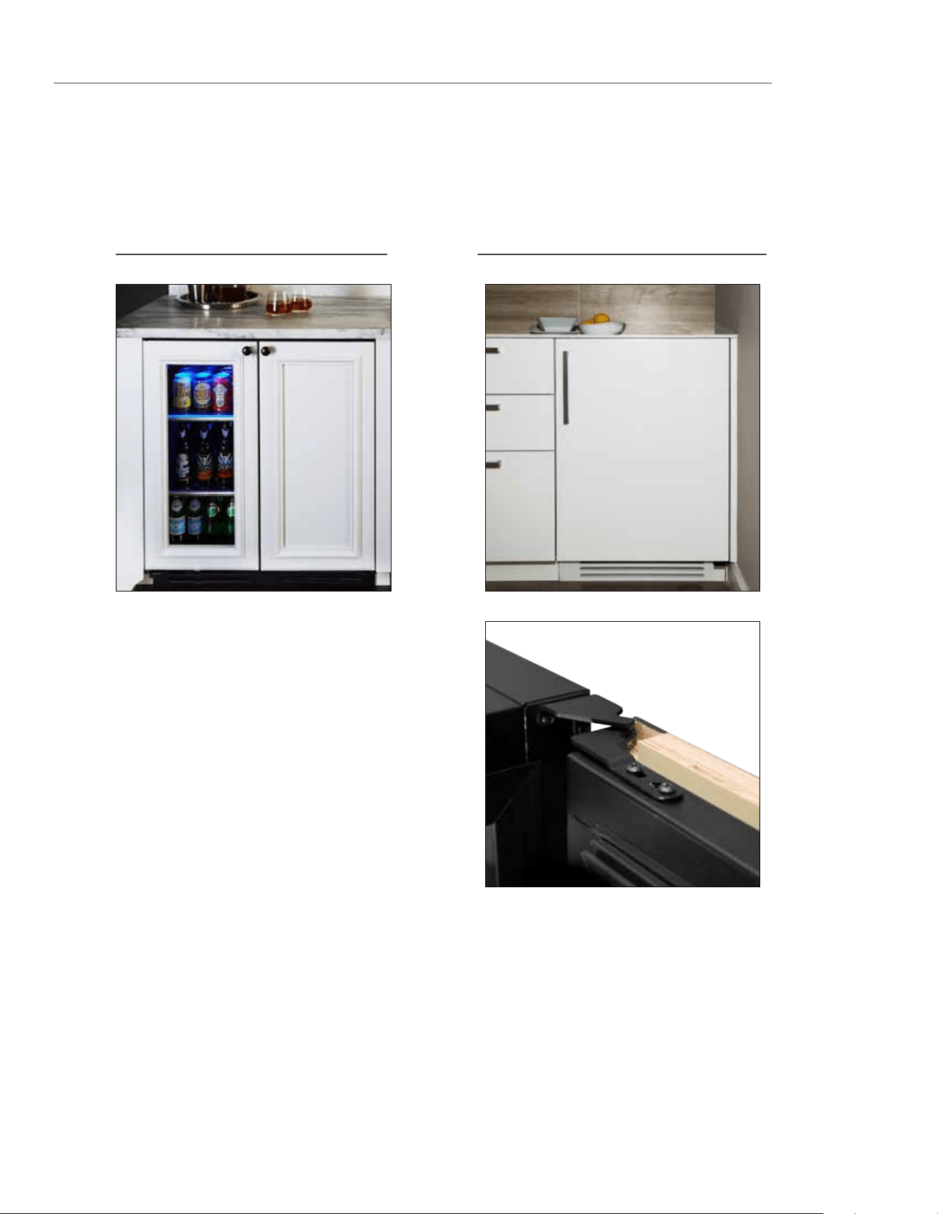
CUSTOM PANEL INSTALLATION - SOLID DOOR REFRIGERATOR / FREEZER
INTEGRATED OVERLAY PANEL
STANDARD OVERLAY PANEL
Overlay units can be fitted with custom panels to match adjacent cabinetry. Two specification options for panels
sizes are given in these instructions for overlay units: Standard overlays and Integrated Panels. The standard
overlay panel dimensions fully cover the provided appliance door. The integrated panel options extend above the
door and conceal the hinge assembly to match full overlay cabinet doors. See pictures below for reference.
21
15 INCH & 24 INCH INSTALL GUIDE
STANDARD OVERLAY PANEL
INTEGRATED OVERLAY PANEL
CUSTOM PANEL INSTALLATION - SOLID DOOR REFRIGERATOR / FREEZER
SOLID DOOR 24 INCH 15 INCH
DOOR PANEL WIDTH 23
5/8
" 14
5/8
"
DOOR PANEL HEIGHT 29
23/32
" 29
23/32
"
DOOR PANEL DEPTH 3/4" max 3/4" max
DOOR PANEL WEIGHT 20 lb. max 20 lb. max
RAIL STYLE DIMENSION 2” min 2” min
SOLID DOOR 24 INCH 15 INCH
DOOR PANEL WIDTH 23
5/8
" 14
5/8
"
DOOR PANEL HEIGHT 30
1/8
" 30
1/8
"
DOOR PANEL DEPTH 3/4" max 3/4" max
DOOR PANEL WEIGHT 20 lb. max 20 lb. max
RAIL STYLE DIMENSION 2” min 2" min
30 1/8"
14 5/8"
3/4"
A
B
5/8"
9/16"
DETAIL A
SCALE 1 : 1
1"
DETAIL B
SCALE 1 : 1
14 5/8"
30 1/8"
14 5/8"
3/4"
A
B
5/8"
9/16"
DETAIL A
SCALE 1 : 1
1"
DETAIL B
SCALE 1 : 1
14 5/8"
30 1/8"
23 5/8"
3/4"
A
B
5/8"
9/16"
1"
23 5/8"
30 1/8"
23 5/8"
3/4"
A
B
5/8"
9/16"
1"
23 5/8"
15 INCH
15 INCH
29
23/32
"29
23/32
"
FRONT
FRONT
24 INCH
FRONT
24 INCH
FRONT
30 1/8"
14 5/8"
3/4"
A
B
5/8"
9/16"
DETAIL A
SCALE 1 : 1
1"
DETAIL B
SCALE 1 : 1
14 5/8"
30 1/8"
14 5/8"
3/4"
A
B
5/8"
9/16"
DETAIL A
SCALE 1 : 1
1"
DETAIL B
SCALE 1 : 1
14 5/8"
30 1/8"
14 5/8"
3/4"
A
B
5/8"
9/16"
DETAIL A
SCALE 1 : 1
1"
DETAIL B
SCALE 1 : 1
14 5/8"
30 1/8"
14 5/8"
3/4"
A
B
5/8"
9/16"
DETAIL A
SCALE 1 : 1
1"
DETAIL B
SCALE 1 : 1
14 5/8"
30 1/8"
23 5/8"
3/4"
A
B
5/8"
9/16"
1"
23 5/8"
15 INCH24 INCH
BACKBACK
22
TRUE RESIDENTIAL
®
SOLID DOOR 24 INCH 15 INCH
DOOR PANEL WIDTH 23
5/8
" 14
5/8
"
DOOR PANEL HEIGHT 30
1/8
” 30
1/8
”
DOOR PANEL DEPTH 3/4" max 3/4" max
DOOR PANEL WEIGHT 10 lb. max 10 lb. max
RAIL STYLE DIMENSION 2” min 2” min
VIEWABLE AREA WIDTH 19
5/8
” 10
5/8
”
VIEWABLE AREA HEIGHT 25
23/32
” 25
23/32
”
SOLID DOOR 24 INCH 15 INCH
DOOR PANEL WIDTH 23
5/8
" 14
5/8
"
DOOR PANEL HEIGHT 29
23/32
" 29
23/32
"
DOOR PANEL DEPTH 3/4" max 3/4" max
DOOR PANEL WEIGHT 10 lb. max 10 lb. max
RAIL STYLE DIMENSION 2” min 2” min
VIEWABLE AREA WIDTH 19
5/8
” 10
5/8
”
VIEWABLE AREA HEIGHT 25
23/32
” 25
23/32
”
STANDARD OVERLAY PANEL
INTEGRATED OVERLAY PANEL
CUSTOM PANEL INSTALLATION - GLASS DOOR REFRIGERATOR
30 1/8"
14 5/8"
3/4"
A
B
5/8"
9/16"
DETAIL A
SCALE 1 : 1
1"
DETAIL B
SCALE 1 : 1
14 5/8"
30 1/8"
14 5/8"
3/4"
A
B
5/8"
9/16"
DETAIL A
SCALE 1 : 1
1"
DETAIL B
SCALE 1 : 1
14 5/8"
30 1/8"
23 5/8"
3/4"
A
B
5/8"
9/16"
1"
23 5/8"
30 1/8"
23 5/8"
3/4"
A
B
5/8"
9/16"
1"
23 5/8"
15 INCH
15 INCH
29
23/32
"29
23/32
"
FRONT
FRONT
24 INCH
FRONT
24 INCH
FRONT
30 1/8"
14 5/8"
3/4"
A
B
5/8"
9/16"
DETAIL A
SCALE 1 : 1
1"
DETAIL B
SCALE 1 : 1
14 5/8"
30 1/8"
14 5/8"
3/4"
A
B
5/8"
9/16"
DETAIL A
SCALE 1 : 1
1"
DETAIL B
SCALE 1 : 1
14 5/8"
30 1/8"
14 5/8"
3/4"
A
B
5/8"
9/16"
DETAIL A
SCALE 1 : 1
1"
DETAIL B
SCALE 1 : 1
14 5/8"
30 1/8"
14 5/8"
3/4"
A
B
5/8"
9/16"
DETAIL A
SCALE 1 : 1
1"
DETAIL B
SCALE 1 : 1
14 5/8"
30 1/8"
23 5/8"
3/4"
A
B
5/8"
9/16"
1"
23 5/8"
15 INCH24 INCH
BACKBACK
23
15 INCH & 24 INCH INSTALL GUIDE
STANDARD OVERLAY PANEL
INTEGRATED OVERLAY PANEL
CUSTOM PANEL INSTALLATION - DRAWER REFRIGERATOR / FREEZER
DRAWER PANEL WIDTH 23
5/8
"
DRAWER PANEL HEIGHT 14
11/16
"
DRAWER PANEL DEPTH 3/4" max
DRAWER PANEL WIDTH 23
5/8
"
TOP DRAWER PANEL HEIGHT 15
1/8
"
BOTTOM DRAWER PANEL HEIGHT 14
11/16
”
DRAWER PANEL DEPTH 3/4" max
SPEC SAME PANEL FOR TOP & BOTTOM FREEZER DRAWERS.
FOR BOTTOM DRAWER ROTATE PANEL 180º.
NOTE: TOP DRAWER WILL EXTEND ABOVE PROVIDED APPLIANCE FRONT
23
5/8
"
14
11/16
”
14
11/16
”
TOP DRAWER -
REFRIGERATOR
BOTTOM DRAWER -
REFRIGERATOR
23
5/8
"
15
1/8
”
14
11/16
”
TOP DRAWER -
REFRIGERATOR
BOTTOM DRAWER -
REFRIGERATOR
23
5/8
"
15
1/8
”
14
11/16
”
TOP DRAWER -
REFRIGERATOR
BOTTOM DRAWER -
REFRIGERATOR
23
5/8
"
14
11/16
”
TOP & BOTTOM DRAWER -
FREEZER
24
TRUE RESIDENTIAL
®
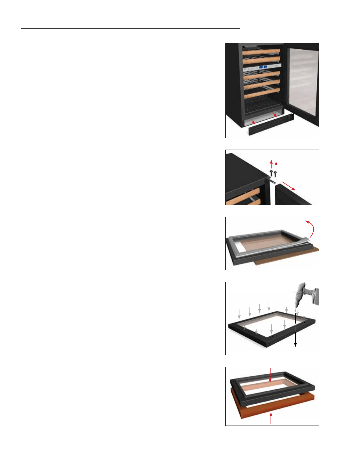
SOLID (OP) AND GLASS FRAMED PANEL (OG) INSTALLATION
Required Tools:
• Phillips Screwdriver
• 3/8" Wrench
• 1/8" Drill Bit
• Ten (10) Screws #6
NOTE: THE LENGTH OF OVERLAY PANEL
MOUNTING SCREWS NEED TO BE 3/4” PLUS
THE THICKNESS OF THE PANEL, MINUS 1/4”.
(3/4”+ THICKNESS OF THE OVERLAY PANEL-
1/4”= LENGTH OF SCREW). TYPES AND LENGTHS
OF SCREWS CAN VARY DEPENDING ON THE
MATERIAL USED
SEE PAGES 21-22 FOR OVERLAY PANEL DIMENSIONS
BEFORE INSTALLING.
FOR EASY OVERLAY INSTALLATION, REFRIGERATOR
DOOR REMOVAL IS REQUIRED.
NOTE: DO NOT INSTALL A SOLID PANEL ON A
GLASS DOOR. THIS MAY CAUSE MOISTURE
TO FORM BEHIND THE PANEL RESULTING IN
DAMAGE.
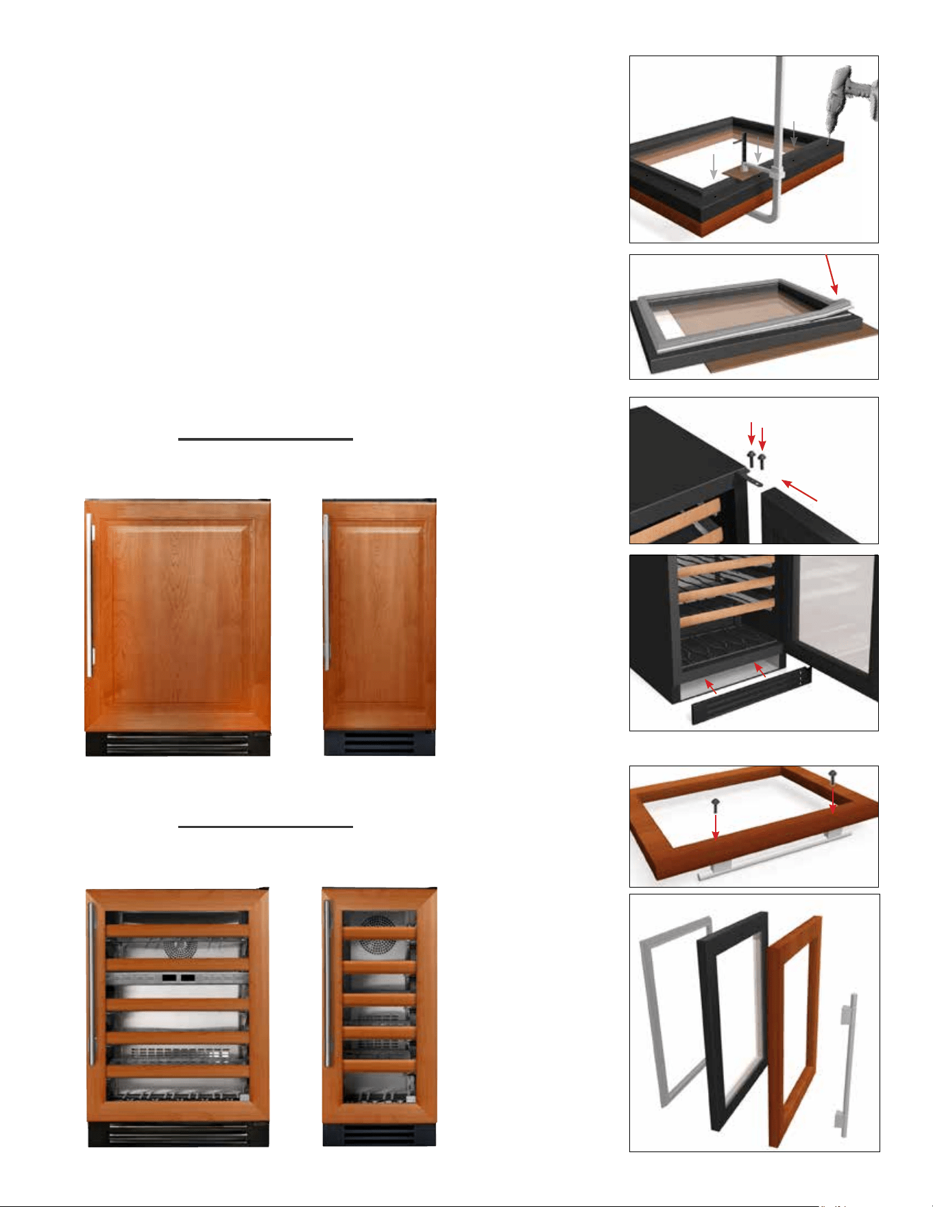
1. Open front door and pull grill forward to remove.
2. To remove door back out two bottom hinge screws
with a 3/8" wrench. Secure door while removing
screws. Remove two Phillips screws from the top
hinge. Save all these screws for later reinstall.
3. Lay door on a safe solid surface. If retrofitting
glass door model be careful not to damage glass.
Lay cardboard or other safe material down before
working on the door. Remove door gasket from the
inside of the door frame. Place gasket to the side
for later reinstall.
4. There are pre marked areas on the front of the
door. Drill these pre marked holes with 1/8" drill
bit. Make sure to go all the way through the door.
NOTE: IF HANDLE IS BEING USED ON OVERLAY
INSTALL IT BEFORE STEP 7 (SEE IMAGE
A). FOR BEST INSTALLATION, SCREWS
ATTACHING HANDLE SHOULD BE RECESSED.
5. It is recommended to clamp the door front on top of
the overlay before drilling pilot holes and installing
anchor screws. The clamp ensures the overlay
panel and door stay aligned with each other while
installing. Once panel is clamped in place, pilot
holes may be drilled into the panel from the rear
side of the door.
1
2
3
4
5
Remove screws
from top and
bottom hinge
25
15 INCH & 24 INCH INSTALL GUIDE
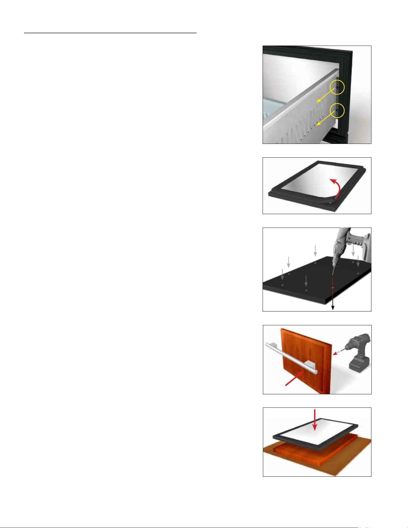
6. Once all holes are pre drilled use the appropriate
specified screws to secure the overlay panel onto
the front of the refrigerator door.
7. Reinstall all components in reverse order. Door
gasket snaps back into place. Overlay panel and
door stay aligned with each other while installing.
6
7
Reinstall screws
on top and
bottom hinge
GASKET DOOR
HANDLE
OVERLAY PANEL
IMAGE A
24 INCH 15 INCH
15 INCH24 INCH
SOLID OVERLAY PANEL
GLASS OVERLAY PANEL
26
TRUE RESIDENTIAL
®
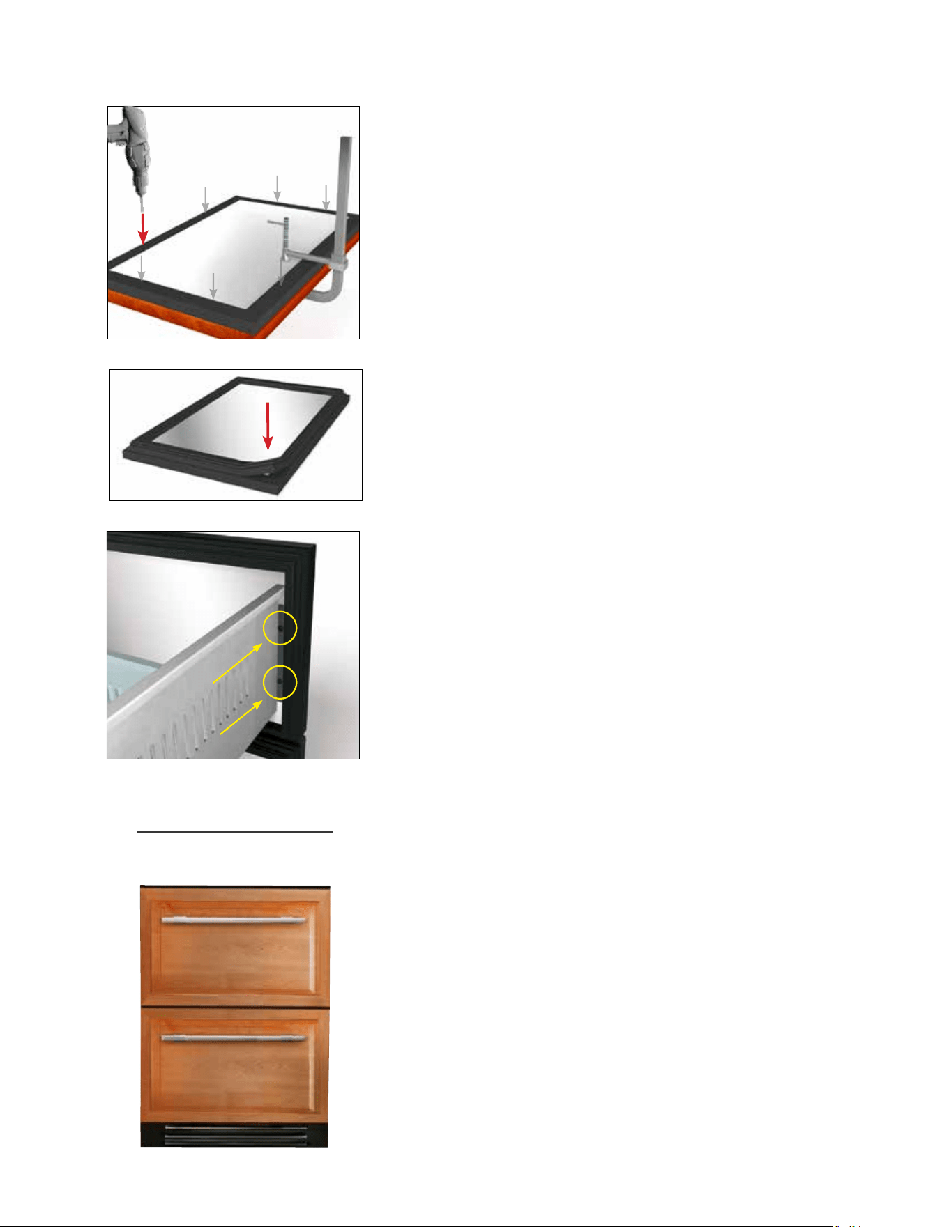
DRAWER OVERLAY PANEL INSTALLATION
Required Tools:
• Phillips Screwdriver
• 1/8" Drill Bit
SEE PAGE 21 FOR OVERLAY PANEL DIMENSIONS
BEFORE INSTALLING.
FOR EASY OVERLAY INSTALLATION, DRAWER FRONT
REMOVAL IS REQUIRED.
1. Open the drawer and detach the front drawer panel
by removing four #2 Phillips screws (two on each
side). (See image 1). Save all these screws for later
reinstallation.
2. Remove front drawer panel gasket.
3. Using a 1/8" drill bit, drill out the eight pilot holes
(each drawer) from the front of the drawer panel.
Drill completely through the panel.
4. Attach drawer handle to the front of the overlay
panel. Attach handle before step 5.
5. Lay overlay panel face-down on a safe solid
surface. Lay drawer panel face-down on top of
the overlay panel. Align panels and secure with a
clamp. Lay cardboard or other soft or safe material
down before working on drawer front.
6. Secure overlay panel to drawer panel using
appropriate size screws.
7. Reattach drawer gasket by pressing and snapping
back into place in gasket channel.
8. Reattach drawer panel front to the drawer using
four screws.
1
2
3
4
5
Front of
drawer
27
15 INCH & 24 INCH INSTALL GUIDE
Back of
drawer
8
7
6
24 INCH
DRAWER OVERLAY PANEL

28
TRUE RESIDENTIAL
®
28 - 35
i n s t a l l a t i O n s p e c i f i c a t i O n s f O r
B e v e r a g e D i s p e n s e r u n i t s
PRESERVE THE MOMENT
®
29
15 INCH & 24 INCH INSTALL GUIDE
25/32
"
8"
12"
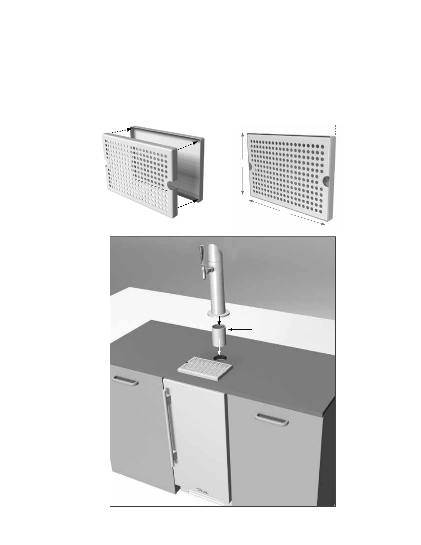
Required Tools:
• 2" Diameter PVC pipe (12" long). Will need to be cut down to size when refrigeration unit is installed
• Silicone Caulk
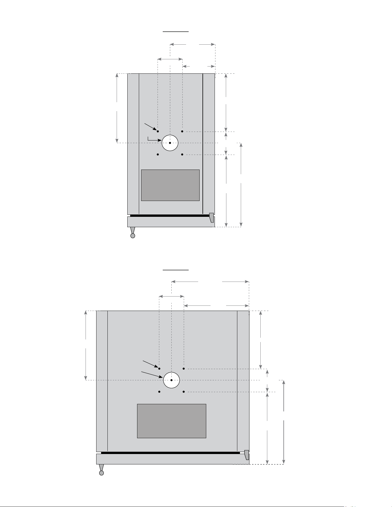
When installing under counter tops use the dimensions in the diagrams for cutting into the counter top.
Silicone caulk around the edge of the PVC pipe after it has been installed.
Assemble drip tray and place it on top of unit as shown.
TAPPER UNIT INSTALLATION UNDER COUNTER TOPS
2" DIAMETER
PVC PIPE
30
TRUE RESIDENTIAL
®
Drip
tray
11
31/32
"
10
5/8
"
9
3/8
"
10
23/32
"
12
13/32
"
13
3/4
"
2
3/8
"O.D.
5/32
"
2
11/16
"
2
11/16
"
Drip
tray
7
7/16
"
6
3/32
"
8
15/16
"
10
9/32
"
12
9/32
"
13
5/8
"
2
3/8
"O.D.
5/32
"
2
11/16
"
2
11/16
"
15 INCH
24 INCH
31
15 INCH & 24 INCH INSTALL GUIDE
INSTALLING DRAFT STANDARD AND HOOK UP
Required Tools:
• Phillips Head Screwdriver
• Adjustable Wrench
• 3/8" I.D. plastic tubing (3’)
• (2) Hose clamps
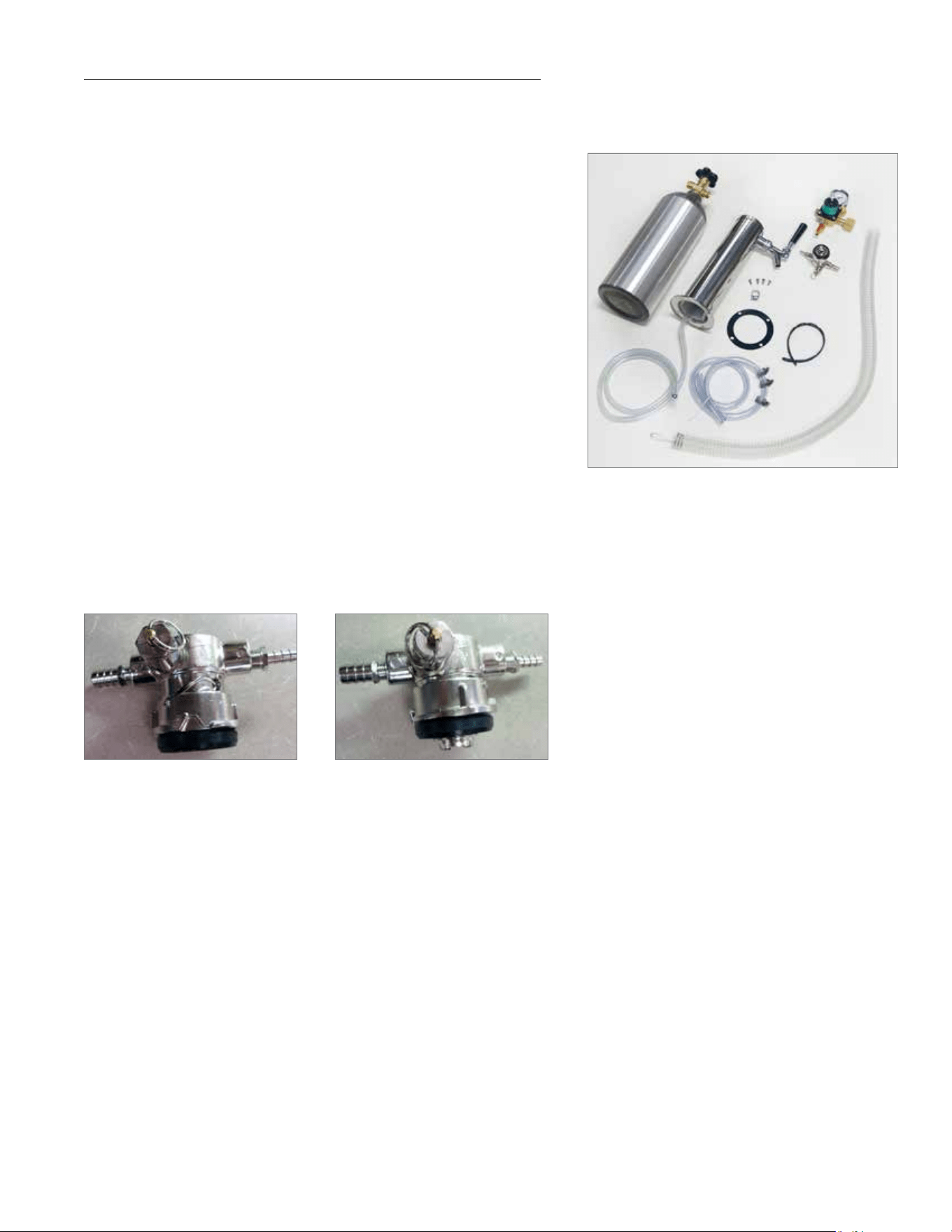
PARTS IN KIT:
1. CO
2
Tank (Shipped empty. Fill before use)
2. Draft Standard
3. Draft Standard Screws
4. Draft Head
5. CO
2
Pressure Regulator (single version/double version)
6. Chill Hose
7. Rubber Washer
8. CO
2
Hose
9. Securing strap
10. Beer Tapper (Sankey, low profile tapper)
1
2
3
4
5
6
7
8
10
9
DISENGAGED ENGAGED
CAUTION: FILLED CO
2
TANKS ARE POTENTIALLY DANGEROUS BECAUSE OF THE PRESSURE
THEY CONTAIN. IF YOU ARE UNFAMILIAR WITH THEIR USE OR THE USE OF THE
CO
2
REGULATOR, SEEK INFORMATION FROM YOUR CO
2
SUPPLIER.
32
TRUE RESIDENTIAL
®
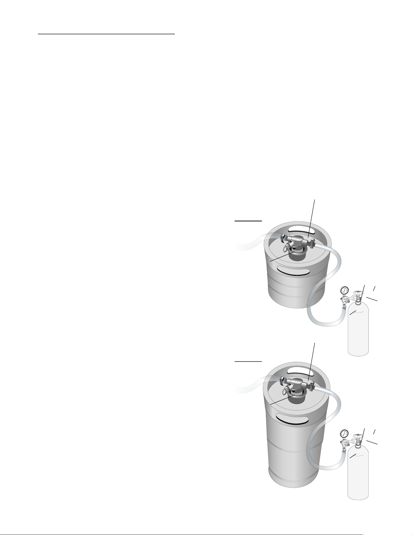
1
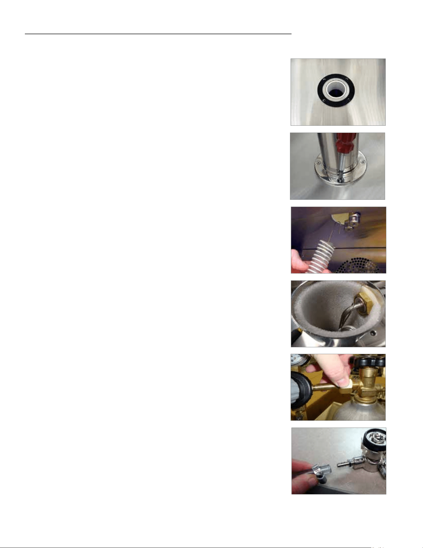
1. Place rubber washer over draft standard mounting holes.
2. Secure the draft standard to the cabinet with the screws provided.
3. Remove the draft cap and run the chill hose to the top of the draft
standard. Hook the hose onto the stainless tube to keep hose from
falling out (This hose will keep the draft standard cold).
4. Reinstall the draft cap.
5. Hook up the pressure regulator to the CO
2
tank. Using a adjustable
wrench make sure the nut is tight.
6. Place CO
2
tank in the unit using the black strap provided. To secure
the tank use one of the screws from the evaporator cover. Connect the
beer hose line from draft tower to tapper. NOTE: Make sure clamp is
on the hose prior to attaching.
2
3
4
5
6
INSTALLING DRAFT STANDARD AND HOOK UP (CONTINUED)
33
15 INCH & 24 INCH INSTALL GUIDE
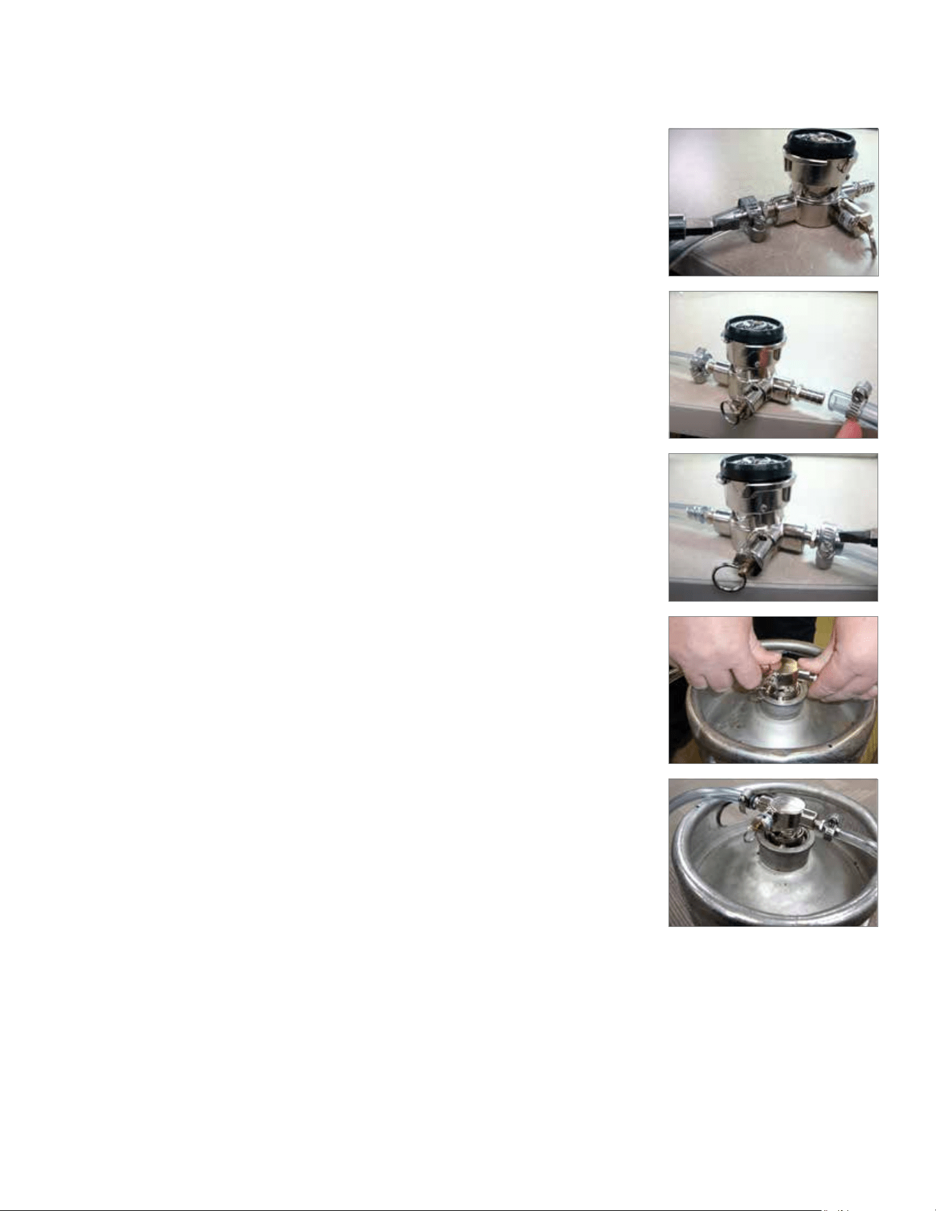
FINAL ASSEMBLY
7
8
9
10
7. Tighten the clamp down on the beer line hose.
8. Connect the CO
2
hose to tapper. NOTE: Make sure clamp is on the
hose prior to attaching.
9. Tighten the clamp down on the CO
2
hose.
10. Install the beer tapper onto the keg. The tapper has notches that
must line up. Once the notches are lined up, turn the tapper to secure
it to the keg.

34
TRUE RESIDENTIAL
®
PRESSURE
DISPENSING PRESSURES DIFFER ACCORDING TO:
• The type of draft dispensing system
• The length of draft dispensing line
• The actual product - some require more, some require less
• The temperature of the product
• The pressurizing agent: air pressure, CO2 or special blended gases
HELPFUL HINTS ON MAINTAINING THE CORRECT PRESSURE
• Know which pressurizing agent to use on which product and why
• Monitor your regulators to ensure applied pressure remains constant
• Keep equipment in good repair
TAPPING
Do not agitate the kegs unnecessarily. If excessive agitation occurs allow kegs to settle for 1 to 2 hours
before tapping. Prior to tapping the keg, ensure that all beer faucet in the serving location are in the off
position. Completely remove the dust cover (identification cap) from the keg.
DRAFT BEER PROBLEMS
TO MINIMIZE DRAFT BEER PROBLEMS, ALWAYS FOLLOW THE RECOMMENDED INSTRUCTIONS
FOR TEMPERATURE AND CO2 PRESSURES FROM YOUR BEER SUPPLIER.
FLAT BEER - DESCRIPTION: FOAMY HEAD DISAPPEARS
QUICKLY. BEER LACKS USUAL ZESTFUL BREWERY FRESH
FLAVOR
• CO
2
turned off when not in use
• Contaminated air source (associated with
compressed air)
• Greasy glasses
• Not enough pressure
• Pressure shut off during night
• Loose tap or vent connection
• Sluggish pressure regulator
• Obstruction in lines
FALSE HEAD - DESCRIPTION: LARGE SOAP-LIKE BUBBLES,
HEAD DISSOLVES VERY QUICKLY
• Dry glasses
• Improper pour
• Pressure required does not correspond to beer
temperature
• Coils or direct draw beer lines warmer than beer
in keg
• Small lines into large faucet shanks
• Beer drawn improperly
WILD BEER - DESCRIPTION: BEER, WHEN DRAWN, IS ALL
FOAM AND NOT ENOUGH LIQUID BEER
• Beer drawn improperly
• Faucet in bad or worn condition
• Kinks, dents, twists or other obstructions in line
• Traps in beer lines
• Beer too warm in kegs or lines
• Too much pressure
• Creeping gauge causing too much pressure
CLOUDY BEER - DESCRIPTION: BEER IN THE GLASS
APPEARS HAZY. NOT CLEAR
• Dirty glass or faucet
• Beer over chilled
• Beer temperature variance in keg. (Beer may
have warmed up at sometime)
• Hot spots in beer lines
• Cutting beer through faucet
• Beer line in poor condition
• Dirty lines
• Beer that has been frozen
BAD TASTE
• Dirty faucet
• Old or dirty beer lines
• Failure to flush beer lines with water after each
empty keg
• Unsanitary conditions at bar
• Foul air or dirt in lines
• Oily air; greasy kitchen air
• Temperature of package too warm
• Dry glasses
35
15 INCH & 24 INCH INSTALL GUIDE
A
A
E
E
B
B
F
F
D
D
C
C
CHANGING CO
2
GAS CYLINDER
FOLLOW THESE INSTRUCTIONS AT ALL TIMES WHEN YOU REPLACE A CO2 GAS CYLINDER:
1. Close cylinder at “A”.
2. Remove tap “D” from barrel. Pull pressure release ring on body of tap to release
pressure remaining in line. (Do not close “C”).
3. Remove or loosen regulator key “B” by turning counter clockwise.
4. Remove regulator from used cylinder at “E”.
5. Remove dust cap from new gas cylinder at “E” and clear dust from outlet by opening and
closing valve “A” quickly using appropriate wrench.
6. Attach regulator to new cylinder at “E”. (Use new fiber/plastic washer, if required).
7. Open valve “A” all the way.
8. Close valve “C”.
9. Adjust regulator key “B” by turning clockwise to set pressure. (Check setting by opening “C”
and pulling and releasing the ring “F” on the pressure release valve on the body of the tap).
10. Tap barrel at “D” with valve “C” open.
NOTE: DO NOT LAY CO2 CYLINDERS FLAT. DO
NOT DROP CO2 CYLINDERS.
IT REQUIRES 1/2 POUND CO2 TO DISPENSE 1/2
BARREL OF BEER AT 38˚F WITH 15 POUNDS
PRESSURE ON BARREL.
PRESSURE ADJUSTMENT ON CO
2
REGULATOR
INCREASING PRESSURE:
1. Close regulator shut-off “C”.
2. Turn regulator key “B” clockwise and make setting.
3. Tap gauge for accurate reading.
4. Open regulator shut-off “C” and draw beer.
DECREASING PRESSURE:
1. Close regulator shut-off “C”.
2. Untap barrel at “D” and to bleed line, activate tap
handle. Leave in open position.
3. Slowly open regulator shut-off “C” and
simultaneously turn regulator key counter-clockwise
to zero reading.
4. Close regulator shut-off “C” and set pressure by
turning regulator key clockwise. Check setting by
opening and closing valve “C”.
5. Close tap head “D”. (Put in “OFF” position).
6. Tap barrel at “D” and open regulator shut-off “C”.
15 INCH
24 INCH
36
TRUE RESIDENTIAL
®
CLEANING INSTRUCTIONS FOR DRAFT TOWERS
Draught dispensers, regardless of design, must be cleaned on a regular
basis. Flushing your draught dispenser with water only is not enough.
Cleaning is recommended whenever changing to a fresh keg.
NOTE: USE CLEANERS APPROVED BY YOUR BEER SUPPLIER
AND FOLLOW THEIR INSTRUCTIONS. IF YOU ARE USING
THE CLEANING KIT PURCHASED FROM TRUE FOLLOW THESE
INSTRUCTIONS:
Cleanliness should be constantly maintained in your dispenser so that
your draught beer will be at its best when served. Although the beer in
the barrel is in excellent condition, it can become less satisfying as it is
drawn through the beer line and faucet if they are not kept clean.
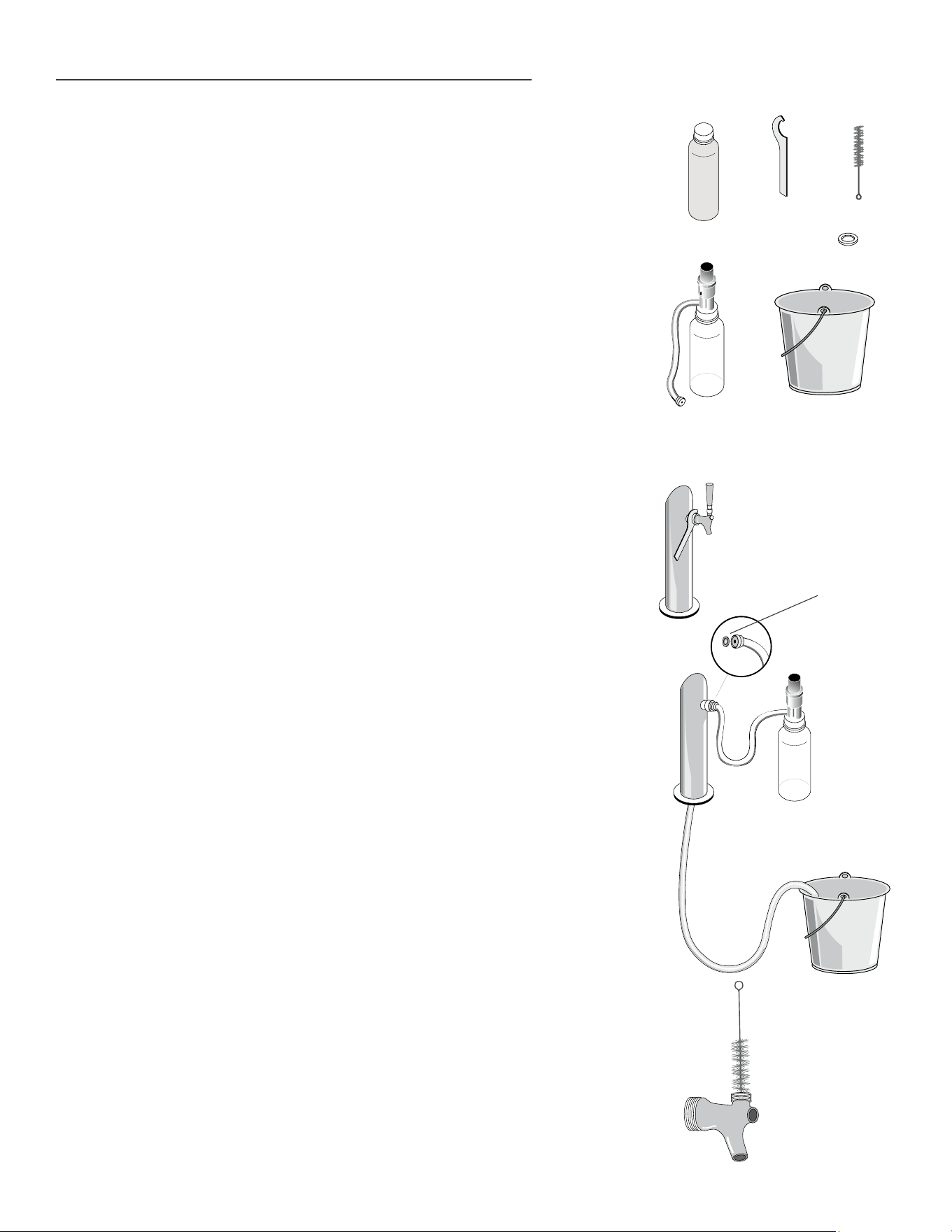
PREPARE SOLUTION:
Add 1/2 ounce (19 grams) of cleaning solution to each quart of warm
water. Fill pump bottle with the mixed cleaning solution.
BEER CLEANING INSTRUCTIONS:
1. Shut-off the CO
2
at the regulator.
2. Remove the tapping device (keg coupler) from the keg.
3. Unscrew handle from faucet.
4. Remove beer faucet with spanner wrench (turn clockwise to remove).
(image 1).
5. Put tap and faucet parts in a bucket.
6. Thread hose from pump bottle to beer column tap outlet (be sure
rubber gasket is in place to prevent leakage) - allow beer line to drain
in bucket. (Image 2).
7. Pump solution from bottle through the beer line(s) into the bucket.
Wait 10 minutes while cleaning solution works through the lines.
8. Use supplied brush to clean beer faucet parts. (Image 3).
9. Rinse parts thoroughly.
10. Rinse bucket, pump bottle and hose thoroughly with clean cool water.
11. Fill pump bottle with clean cool water and pump through lines until
water runs clear. (repeat if necessary)
12. When crystal clear water comes through, you’re ready to assemble
and reattach faucet and re-tap the keg.
BEER TAP CLEANING KIT
REQUIRED TOOLS
2
BLC SYSTEM
CLEANER
SPANNER
WRENCH
BRUSH
BUCKET AND
FRESH WATER
PUMP BOTTLE
AND TUBE
RUBBER
GASKET
RUBBER
GASKET
3
1

37
15 INCH & 24 INCH INSTALL GUIDE
i n s t a l l i n g t O e K i c K
l e v e l i n g r e f r i g e r a t O r
i n s t a l l i n g a n t i -t i p B r a c K e t s
i n s t a l l i n g t h e 1 2 0 ° D O O r s t O p ( s t a n D a r D )
i
n s t a l l i n g t h e 9 0 ° D O O r s t O p ( O p t i O n a l )
36 - 39
PRESERVE THE MOMENT
®
38
TRUE RESIDENTIAL
®
TOE KICK IS ATTACHED
TO BACK OF UNIT
INSTALLING THE TOE KICK
1. Remove from package that is taped to back of unit
2. Line up and attach the toe kick to the bottom of the cabinet using the magnets.
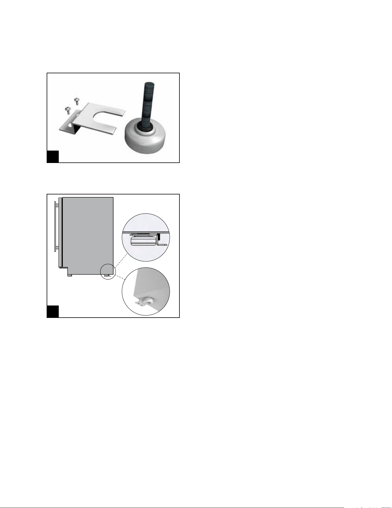
LEVELING REFRIGERATOR
1. Set unit in its final location. Be sure there is adequate ventilation in your room.
2. Proper leveling of your True unit is critical to operating success (for non-mobile models). Effective condensate
removal and door operation will be effected by leveling. Adjust leg levelers on the front and back of the
cabinet if it needs to be lowered or raised.
3. The unit should be leveled from the interior of the unit front to back and side to side with a level. If the
refrigerator is not level adjust the stainless steel leg levelers. The leg levelers can be adjusted by turning to
reach the desired leveling height as shown in the illustration below.
4. Free plug and cord from back of cooler (do not plug in).
5. The unit should be placed close enough to the electrical supply so that extension cords are never used.
6. Once installed in final location, insert toe kick by clipping in place.
WARNING: COMPRESSOR WARRANTIES ARE VOID IF THE UNIT IS MORE THAN
7 FT. (2.1M) FROM PLUG-IN CONNECTION OR IF AN EXTENSION CORD IS USED.
39
15 INCH & 24 INCH INSTALL GUIDE
PRODUCT ADVISEMENT
ANTI-TIP BRACKET INSTALLATION
1
3.23.17 AC
TRUE RESIDENTIAL
®
211354
*211354*
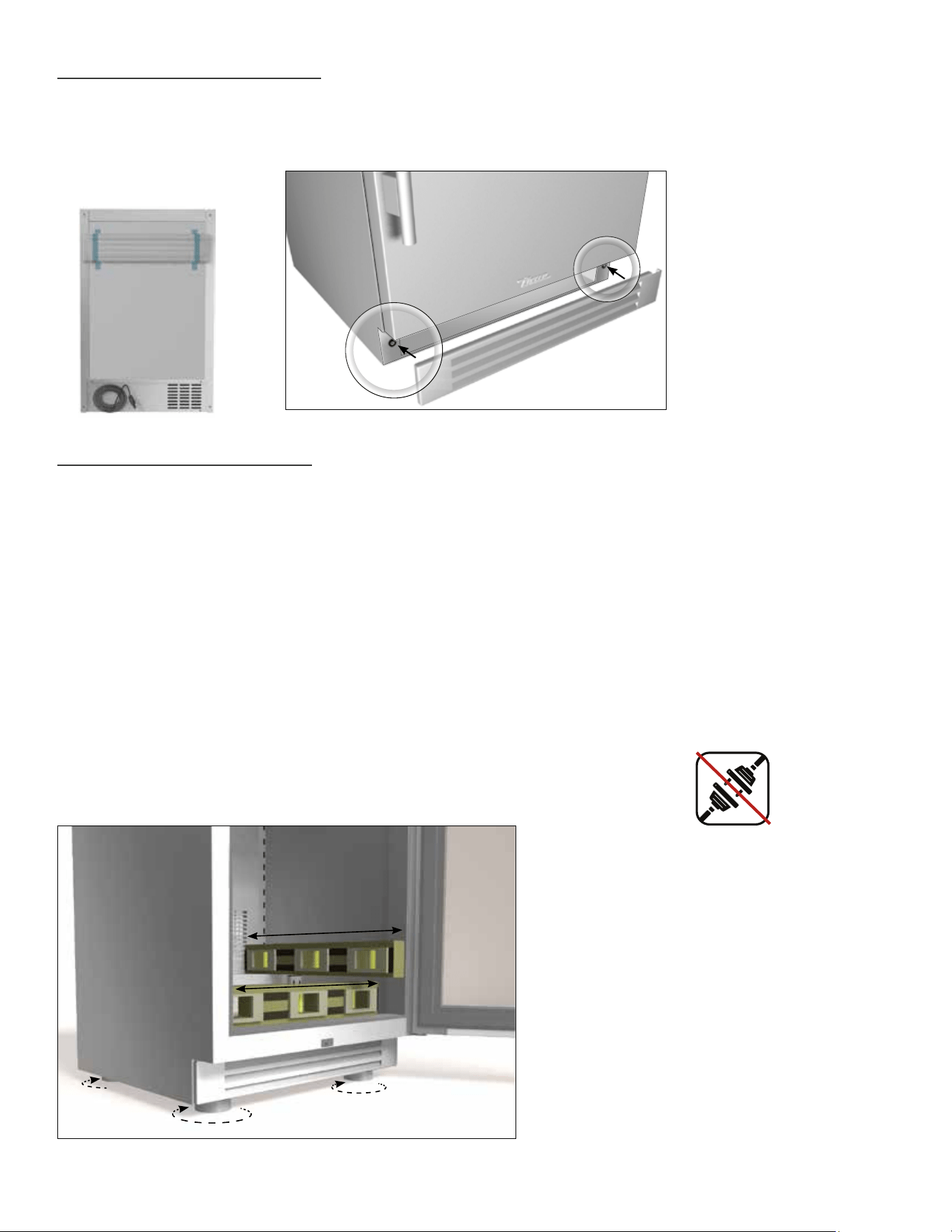
STEP 1
Determine the location of the unit. The anti-tip
brackets will be installed 27/32" inset from the back
and sides of the unit. You can also measure 18 1/2"
from the front of the unit (not including the lower
louver grill). Using the bracket as a template, mark
the holes for drilling.
ALL FREE STANDING DRAWER (TUR-24D) OR STACKED UNITS MUST HAVE ANTI-TIP BRACKETS INSTALLED.
TIP-OVER HAZARD: A CHILD OR ADULT CAN TIP THE REFRIGERATOR. FAILURE TO FOLLOW THESE INSTRUCTIONS CAN RESULT
IN PROPERTY OR BODILY HARM.
BEFORE MOVING UNIT TAKE PRECAUTIONS TO PROTECT THE FLOOR.
Read all installation instructions first. Install the anti-tip brackets to hold both rear legs of the unit. Follow these steps
to secure the brackets to the floor before moving the unit into final operating position.
Contact a qualified floor installer for the best procedure of drilling mounting holes through your type of floor.
TOOLS REQUIRED
• Power drill
• Measuring Tape
KIT INCLUDES
• 2 Anti-tip brackets
• 4 Concrete screws (blue)
• 4 Wood screws (brass)
IMPORTANT!
1
ANTI-TIP BRACKET (TOP VIEW)
Back
Front
27/ 32"
22
3/16"
18
1/2"
40
TRUE RESIDENTIAL
®
PRODUCT ADVISEMENT
ANTI-TIP BRACKET INSTALLATION
2
3.23.17 AC
TRUE RESIDENTIAL
®
211354
*211354*
STEP 3
Move unit into final position making sure rear leveling
legs slide into the anti-tip brackets.
STEP 2
To mount the anti-tip bracket to wood floor, drill pilot
holes for each of the bracket holes. To mount the
anti-tip bracket to concrete or ceramic floor use a
masonry bit to drill pilot holes. Align anti-tip bracket
holes with the holes in the floor. Fasten anti-tip
bracket with screws provided using the brass colored
screw for wood, or blue colored masonry screw for
concrete.
2
3
41
15 INCH & 24 INCH INSTALL GUIDE
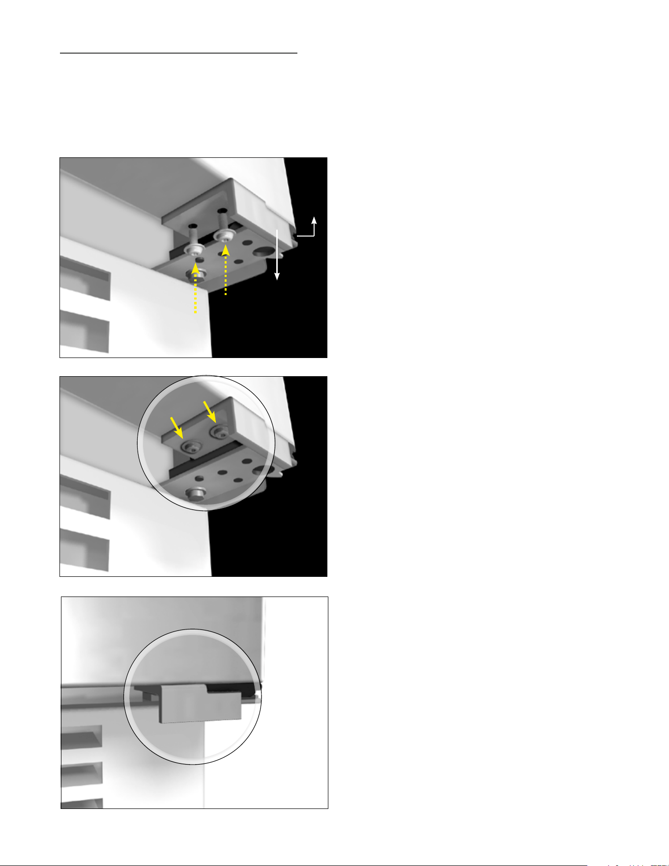
INSTALLING THE 120° DOOR STOP
All units are provided with an optional door stop. When installed, the door stop will restrict the door from opening
past approximately 120º to prevent damage to surrounding cabinets. To install the door stop, use the 2 screws
provided and secure the bracket to the bottom of the door on the same side as the hinge.
Cabinet door
Door stop
installed
Cabinet grill
Hinge
Door stop
42
TRUE RESIDENTIAL
®
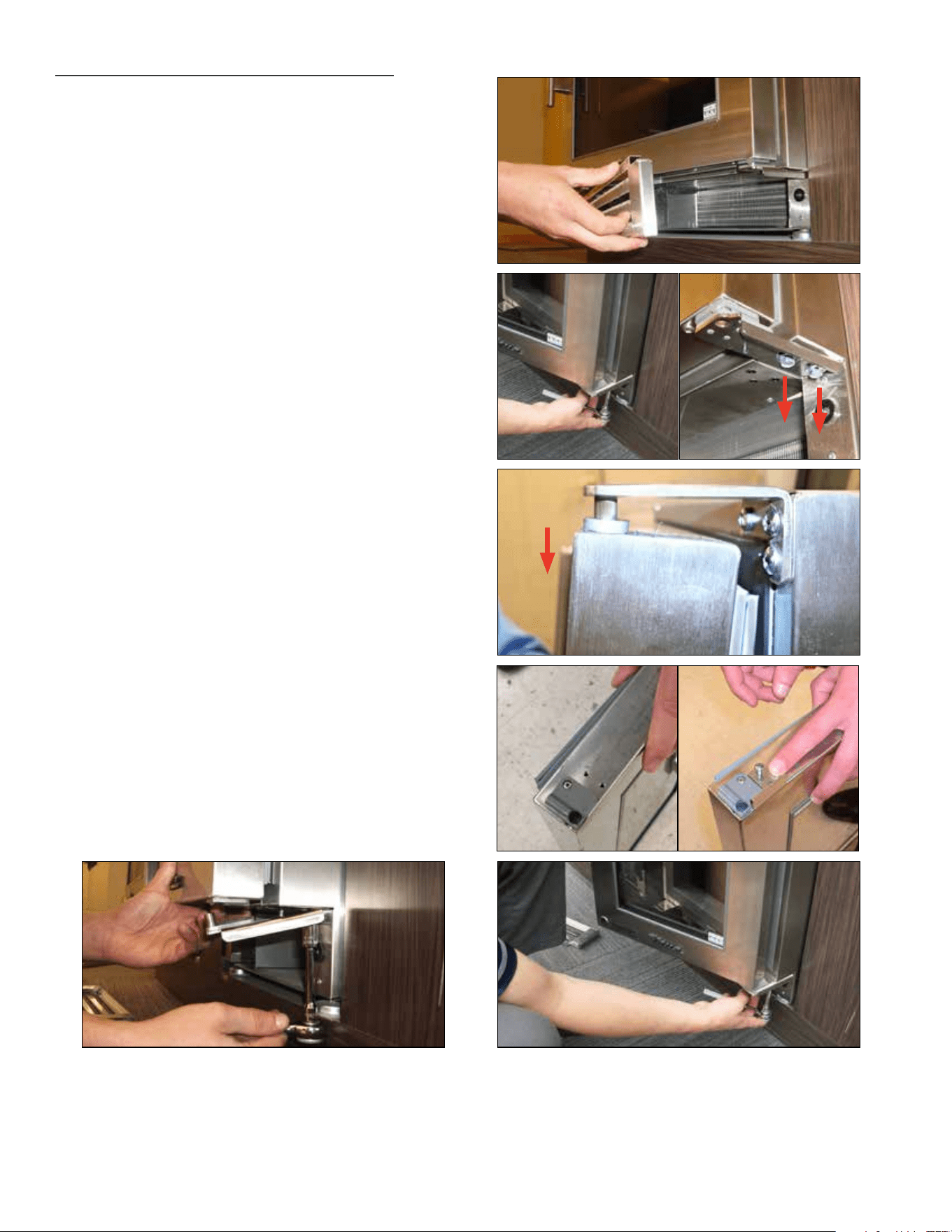
REQUIRED TOOLS:
• 3/8” Socket wrench
• Phillips screwdriver
KIT:
• 90º Hinge door stop
• Door stop bracket
1. Remove toe kick.
2. WARNING: Support the door while removing
hinge. Door is heavy and weight will cause it to
drop if not supported.
Remove 2 3/8” bolts to detach 120º door hinge
(standard).
3. Slowly remove door from unit by sliding down
from top hinge.
4. Install door stop using screws already installed.
Reinstall door by sliding up into top hinge.
5. Install 90º hinge with the 2 3/8” bolts that you
removed. Note: Do not tighten screws all the way
until door adjustments have been made.
6. Align door with lock latch and light switch.
Tighten screws.
2
3
4
5 6
INSTALLING THE 90° DOOR STOP
1

43
15 INCH & 24 INCH INSTALL GUIDE
40 - 49
t r u e p r e c i s i O n c O n t r O l
®
O p e r a t i O n
a n D c a B i n e t c O m p O n e n t s
( a l l m O D e l s )
2 4 i
n c h r e f r i g e r a t O r & f r e e z e r
2 4 i n c h D u a l z O n e w i n e c a B i n e t
2 4 i n c h r e f r i g e r a t O r D r a w e r s
2 4 i n c h f r e e z e r D r a w e r s
1 5 i n c h r e f r i g e r a t O r
h O m e a l a r m s y s t e m
s h e l v i n g a D j u s t m e n t
s t a c K i n g K i t i n s t r u c t i O n s
PRESERVE THE MOMENT
®
44
TRUE RESIDENTIAL
®
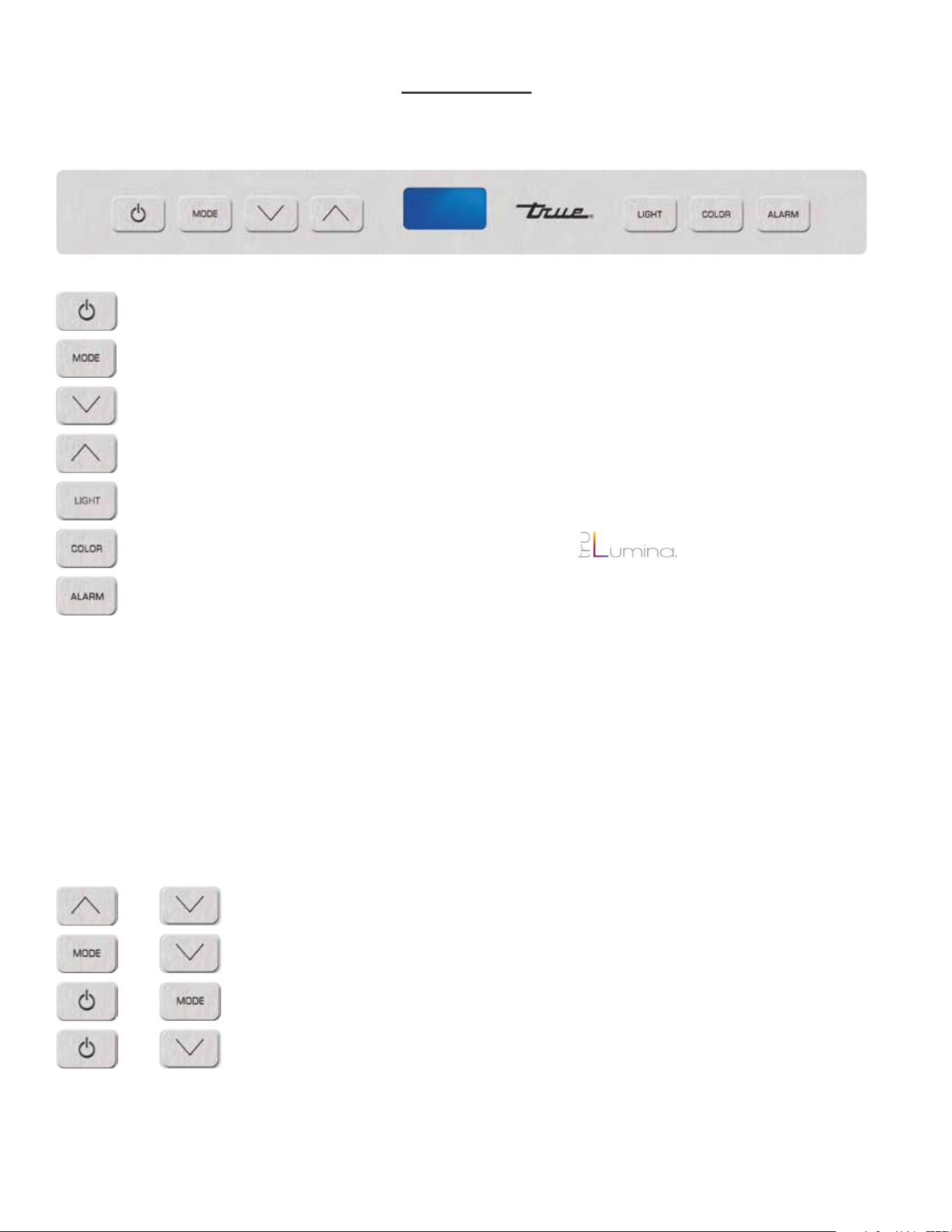
24 INCH REFRIGERATOR & FREEZER
(FREEZER NOT AVAILABLE IN GLASS DOOR)
Power unit off / on cuts power to all relays
To display set point
Press to change set point down
Press to change set point up
To turn on accent light - This will leave light on all the time even when the door is closed
To switch color LED’s - 14 color TruLumina
®
patent.
To turn on door ajar alarm & high temperature alarm - Door ajar alarm activates after 7 minutes.
• Refrigerator - High temperature alarm activates after one consecutive hour at or above 50°F.
• Freezer - High temperature alarm activates after one consecutive hour at or above 20° F.
• Wine Cabinet - High temperature alarm activates after one consecutive hour at or above 70°F.
=
=
=
=
=
=
=
Lock / Unlock Keypad
Sabbath Mode
Showroom Mode - Shuts off all refrigeration components. Displays set point.
Lights are fully functional.
Toggle °C / °F
+ =
=
=
=
+
+
+
KEY COMBINATIONS
45
15 INCH & 24 INCH INSTALL GUIDE
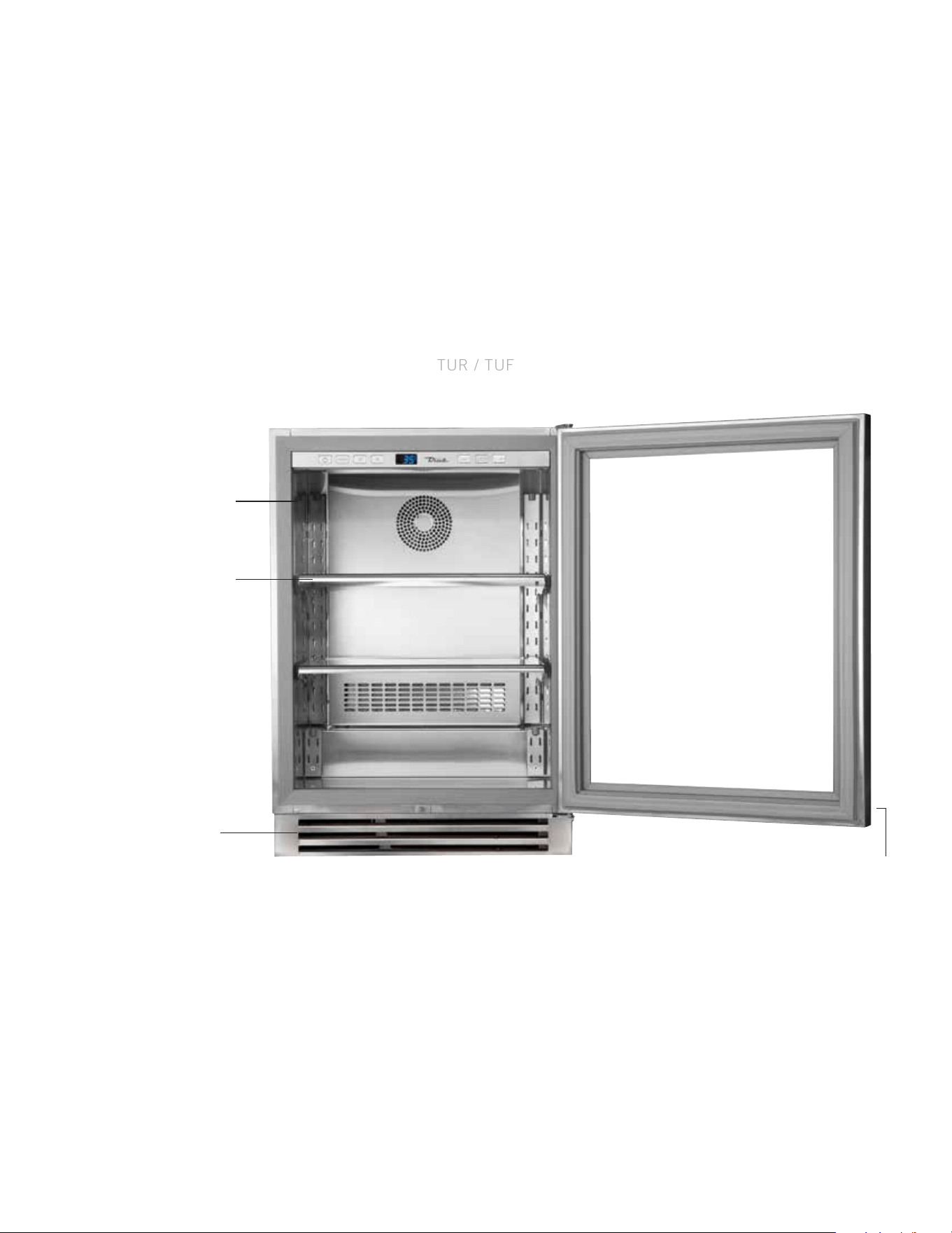
TRUE ALL REFRIGERATOR / FREEZER COMPONENTS
TUR / TUF
REMOVABLE KICK PLATE
FOR EASY CLEANING
DOOR LOCK
ADJUSTABLE STAINLESS
STEEL GLASS SHELVES (2)
LOCATION OF SERIAL TAG
46
TRUE RESIDENTIAL
®
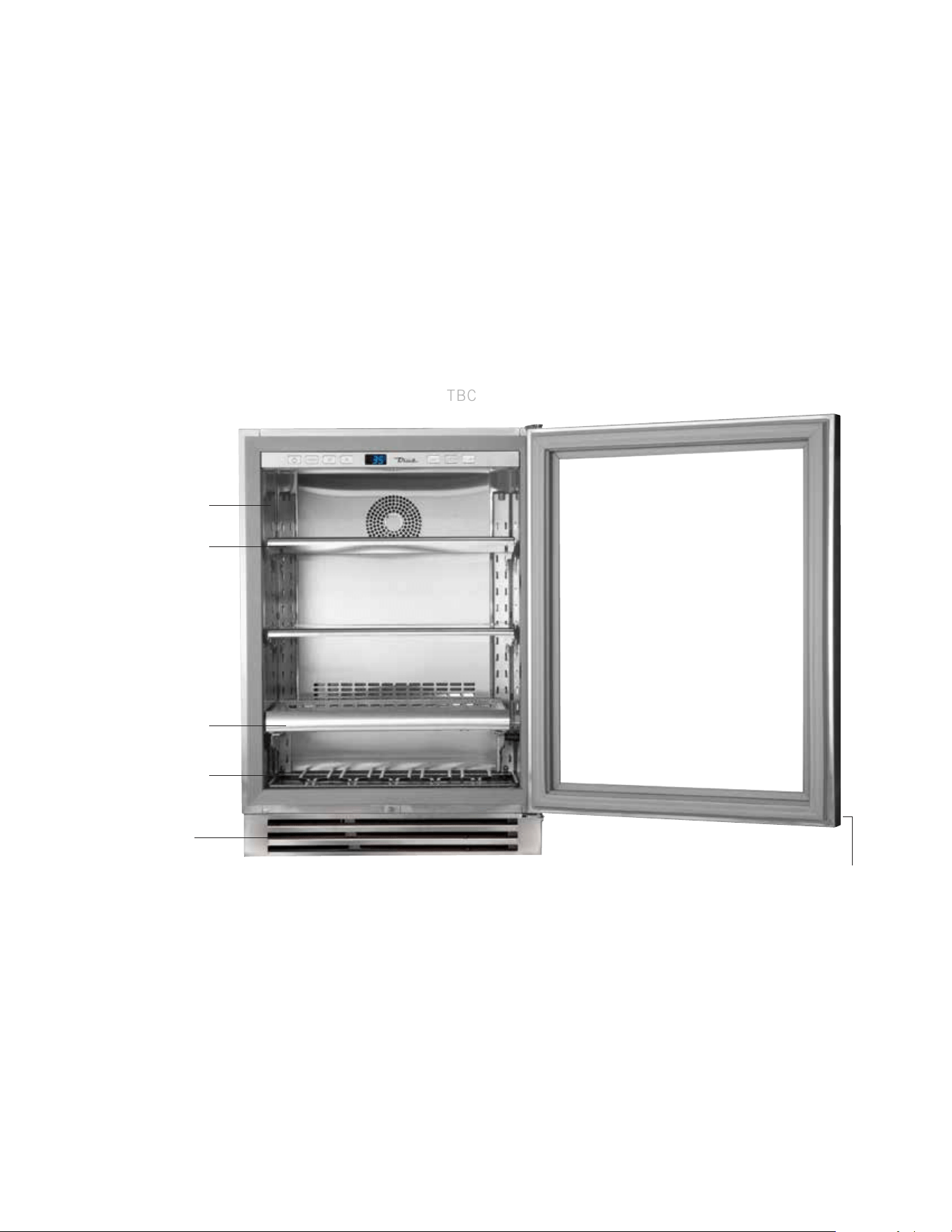
TRUE BEVERAGE CENTER COMPONENTS
TBC
REMOVABLE KICK PLATE
FOR EASY CLEANING
ADJUSTABLE STAINLESS
STEEL GLASS SHELVES (2)
SLIDE OUT WINE SHELF (1)
FLOOR WINE CRADLE (1)
LOCATION OF SERIAL TAG
DOOR LOCK
47
15 INCH & 24 INCH INSTALL GUIDE
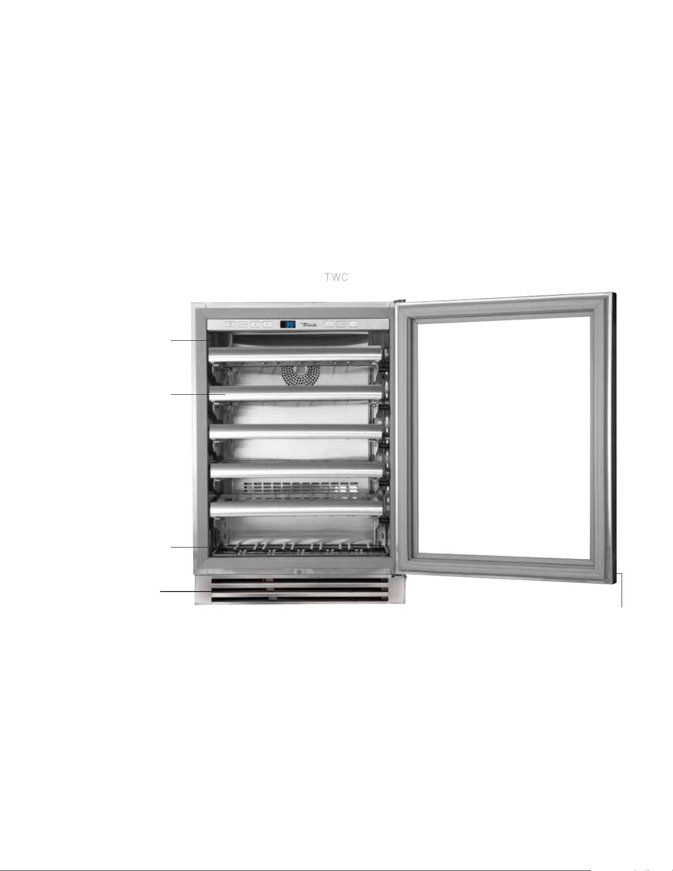
TRUE WINE CABINET COMPONENTS
TWC
REMOVABLE KICK PLATE
FOR EASY CLEANING
FLOOR WINE CRADLE (1)
ADJUSTABLE SLIDE OUT
WINE SHELVES (5)
LOCATION OF SERIAL TAG
DOOR LOCK
48
TRUE RESIDENTIAL
®
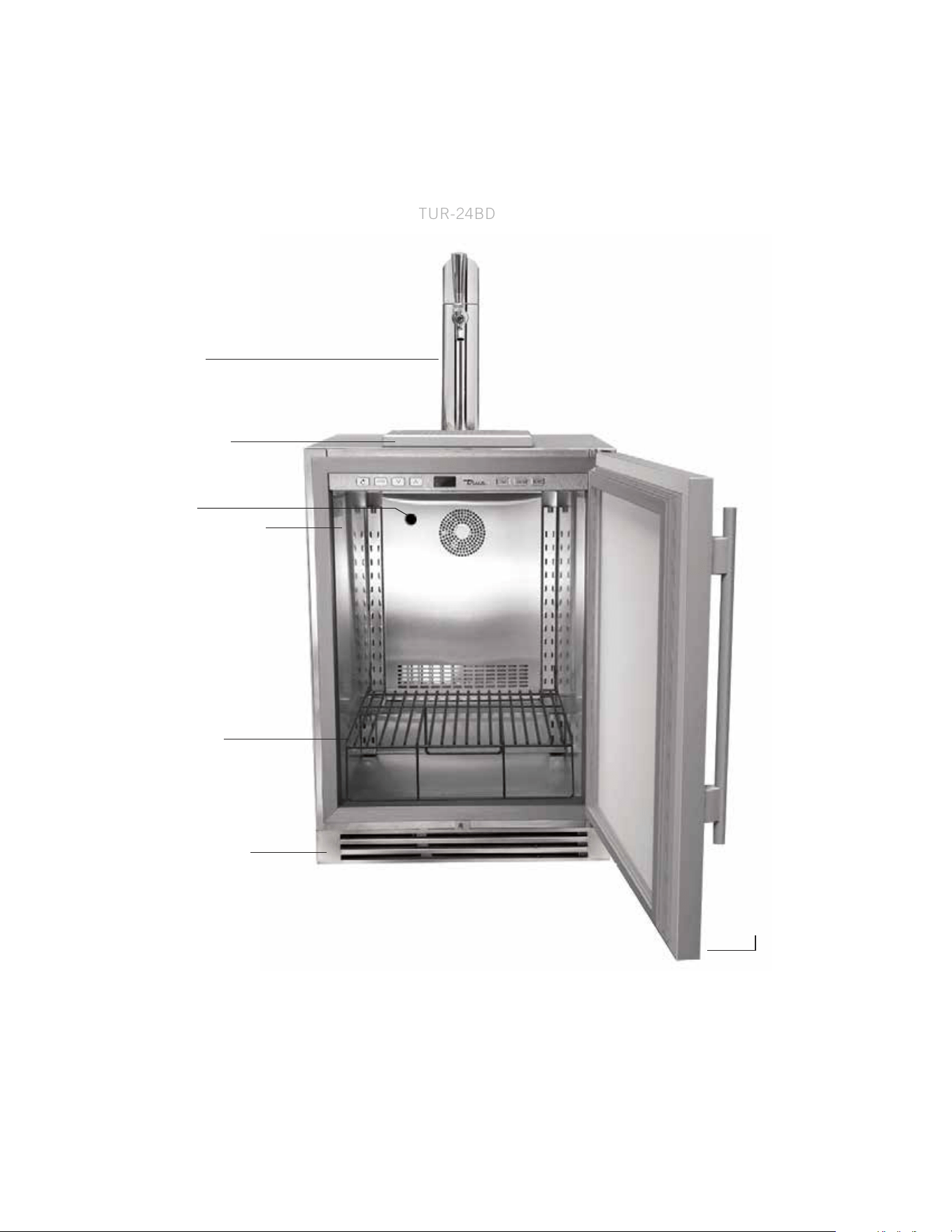
TRUE BEVERAGE DISPENSER
TUR-24BD
REMOVABLE KICK PLATE
FOR EASY CLEANING
DOOR LOCK
SHELF (1)
FOR USE WITH 1/4
SHORT KEG ONLY
LOCATION OF SERIAL TAG
CHILL HOSE
SPILL GRATE (TOP)
DRIP PAN (BOTTOM)
DRAFT TOWER
49
15 INCH & 24 INCH INSTALL GUIDE
SHELF (1)
FOR USE WITH 1/4
SHORT KEG ONLY
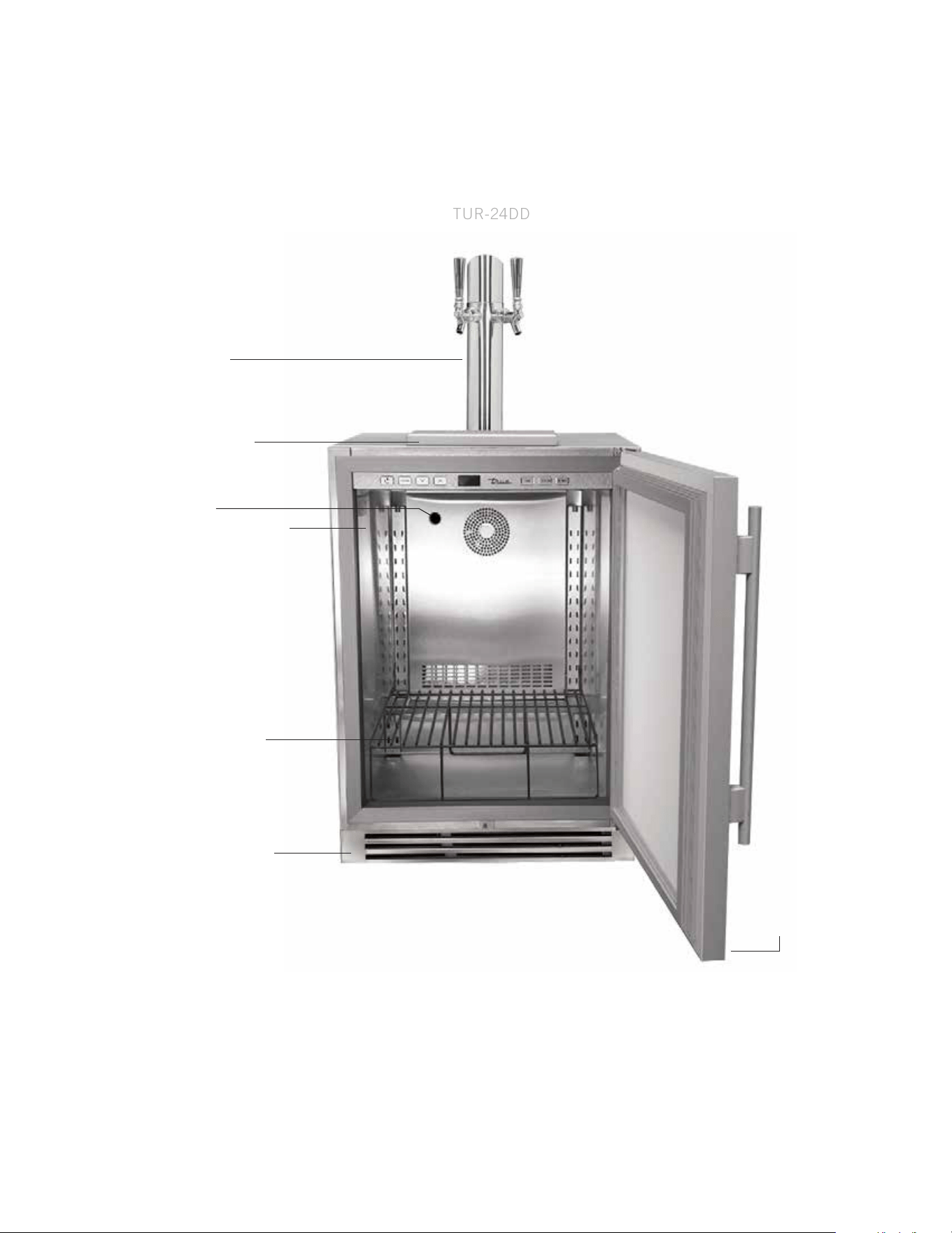
TRUE DUAL BEVERAGE DISPENSER
TUR-24DD
DOUBLE
DRAFT TOWER
REMOVABLE KICK PLATE
FOR EASY CLEANING
DOOR LOCK
LOCATION OF SERIAL TAG
CHILL HOSE
SPILL GRATE (TOP)
DRIP PAN (BOTTOM)
50
TRUE RESIDENTIAL
®
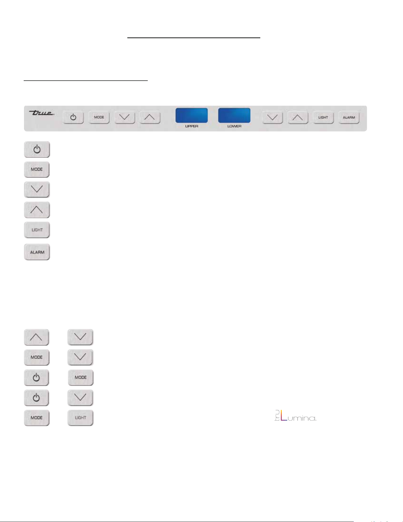
24 INCH DUAL ZONE
USER INTERFACE COMMANDS
Lock / Unlock Keypad (UPPER)
Sabbath Mode (UPPER)
Showroom Mode - Shuts off all refrigeration components. Displays set point.
Lights are fully functional.
Toggle °C / °F (UPPER)
To switch color LEDs - 14 color TruLumina
®
patent.
Power, cuts power to all relays, resumes pulldown
To display set point
Press to change set point down, hold to scroll down
Press to change set point up, hold to scroll up
To turn on Accent Light - This will leave light on all the time even when the door is closed
To turn on door ajar alarm & high temperature alarm - Door ajar alarm activates after 7 minutes.
• High temperature alarm activates after one consecutive hour at or above 70°F.
=
+ =
=
=
=
=
+
+
+
+
=
=
=
=
=
KEY COMBINATIONS
51
15 INCH & 24 INCH INSTALL GUIDE
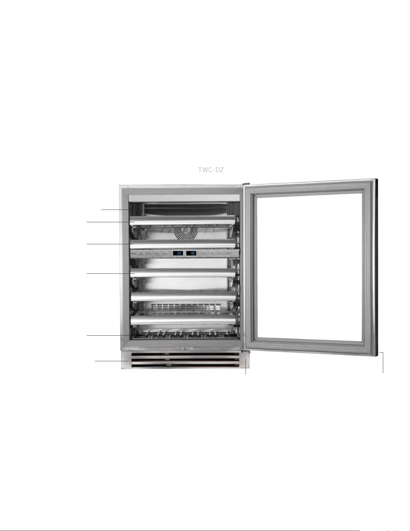
TRUE WINE CABINET - DUAL ZONE COMPONENTS
TWC-DZ
REMOVABLE KICK PLATE
FOR EASY CLEANING
HOME
SECURITY
TIE IN
REMOVABLE WINE
CRADLE (1)
NON-ADJUSTABLE
SHELF (1)
FULLY ADJUSTABLE
WINE SHELF (1)
FULLY ADJUSTABLE
WINE SHELVES (3)
LOCATION OF SERIAL TAG
DOOR LOCK
52
TRUE RESIDENTIAL
®
24 INCH REFRIGERATOR / FREEZER DRAWERS
Lock / Unlock Keypad
Sabbath Mode
Showroom Mode - Shuts off all refrigeration components. Displays set point.
Lights are fully functional.
Toggle °C / °F
Power unit off / on cuts power to all relays
To display set point
Press to change set point down
Press to change set point up
To turn on accent light - This will leave light on all the time even when the door is closed
To switch color LED’s - 14 color TruLumina
®
patent.
To turn on door ajar alarm & high temperature alarm - Door ajar alarm activates after 7 minutes.
• Refrigerator - High temperature alarm activates after one consecutive hour at or above 50°F.
• Freezer - High temperature alarm activates after one consecutive hour at or above 20°F.
=
+ =
=
=
=
+
+
+
=
=
=
=
=
=
KEY COMBINATIONS
53
15 INCH & 24 INCH INSTALL GUIDE
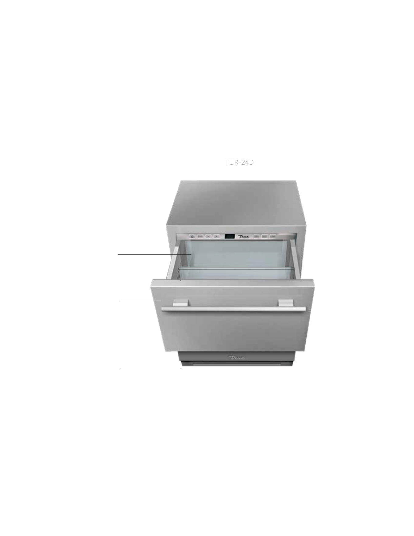
TRUE REFRIGERATED DRAWERS
TUR-24D
REMOVABLE KICK PLATE
FOR EASY CLEANING
EXCLUSIVE TRUE
®
-GLIDE
SOFT-CLOSE FEATURE
FOR BOTH DRAWERS
TWO HEAVY DUTY
LEXAN ORGANIZERS
PER DRAWER
54
TRUE RESIDENTIAL
®
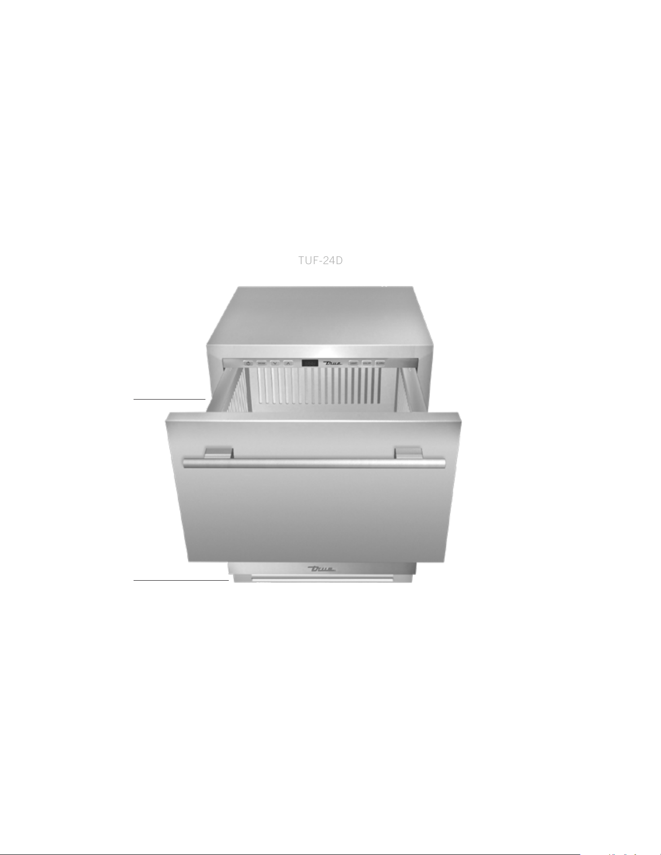
TRUE FREEZER DRAWERS
TUF-24D
REMOVABLE KICK PLATE
FOR EASY CLEANING
EXCLUSIVE TRUE
®
-GLIDE
SOFT-CLOSE FEATURE
FOR BOTH DRAWERS

55
15 INCH & 24 INCH INSTALL GUIDE
NOTES
56
TRUE RESIDENTIAL
®
15 INCH
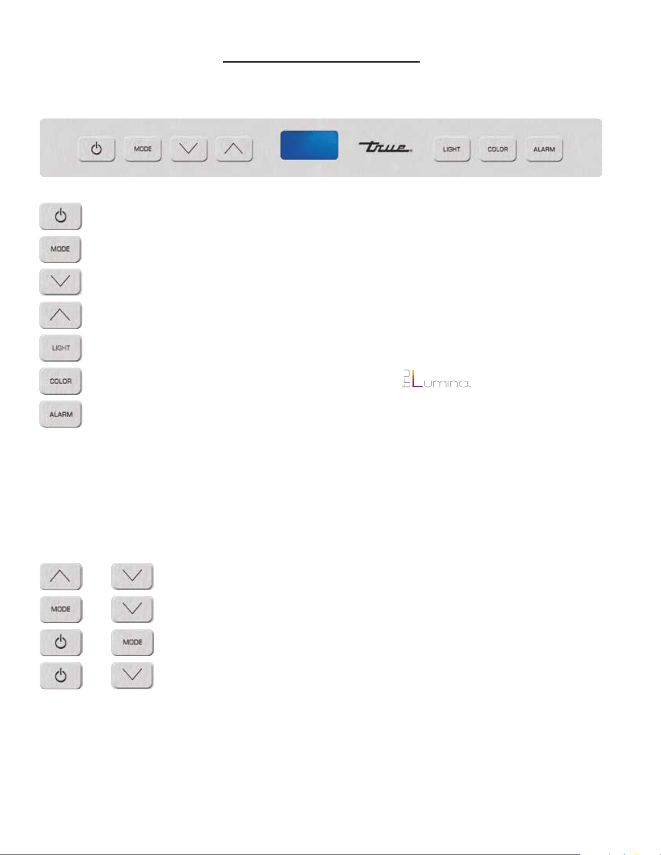
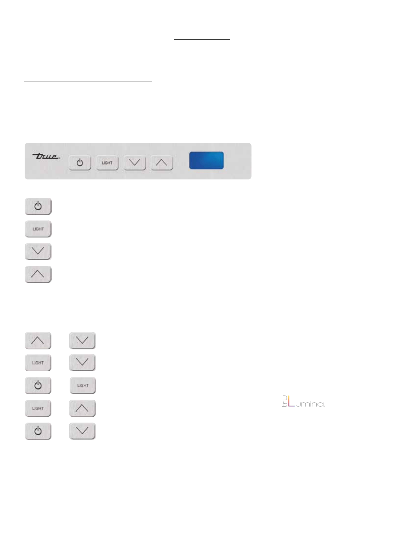
USER INTERFACE COMMANDS
Control is located behind the user interface and can be accessed by removing 3 Phillips screws. This will also
give you access to the user interface, and LED driver. Control sequence is as follows:
=
=
=
=
Power, cuts power to all relays, resumes pulldown
To turn on Accent Light
Press to change set point down, hold to scroll down
Press to change set point up, hold to scroll up
KEY COMBINATIONS
Lock / Unlock Keypad
Sabbath Mode
Showroom Mode - Shuts off all refrigeration components. Displays set point. Lights
are fully functional.
To switch color LEDs - 14 color TruLumina
®
patent.
To turn on door ajar alarm & high temperature alarm - Door ajar alarm activates
after 7 minutes.
• Refrigerator - High temperature alarm activates after one consecutive hour at or
above 50°F.
• Wine Cabinet - High temperature alarm activates after one consecutive hour at
or above 70°F.
+ =
=
=
=
=
+
+
+
+
57
15 INCH & 24 INCH INSTALL GUIDE
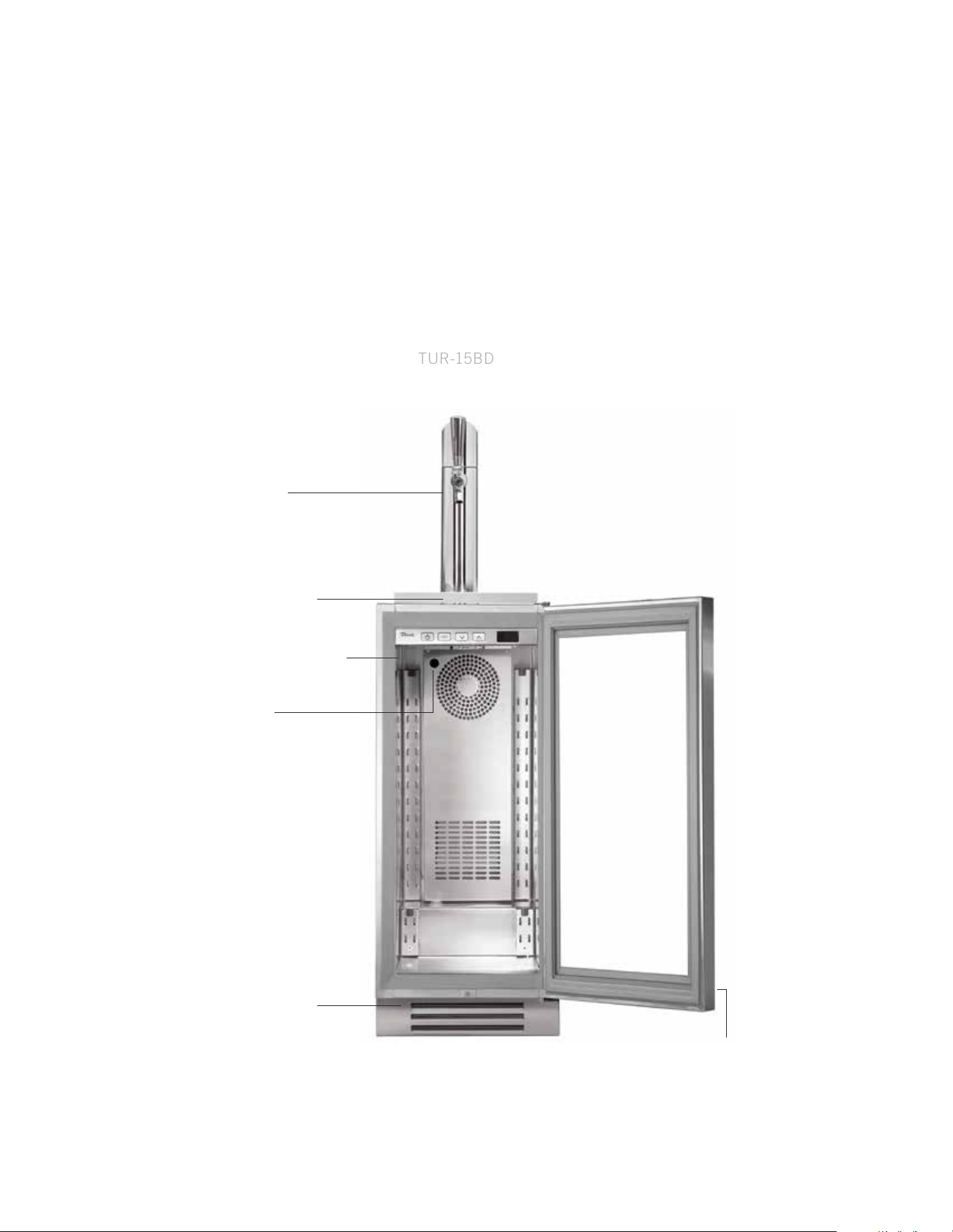
TRUE BEVERAGE DISPENSER
TUR-15BD
LOCATION OF SERIAL TAG
CHILL HOSE
DRAFT TOWER
SPILL GRATE (TOP)
DRILL PAN (BOTTOM)
REMOVABLE KICK PLATE
FOR EASY CLEANING
DOOR LOCK
58
TRUE RESIDENTIAL
®
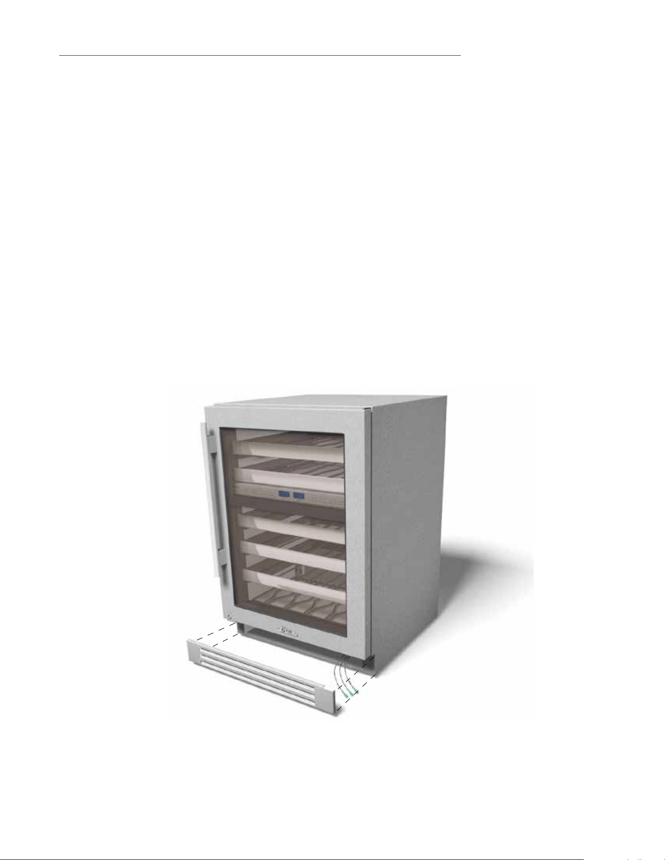
TRUE ALL REFRIGERATOR COMPONENTS
TUR
LOCATION OF SERIAL TAG
REMOVABLE KICK PLATE
FOR EASY CLEANING
DOOR LOCK
ADJUSTABLE SPILL PROOF
GLASS SHELVES (2)
59
15 INCH & 24 INCH INSTALL GUIDE
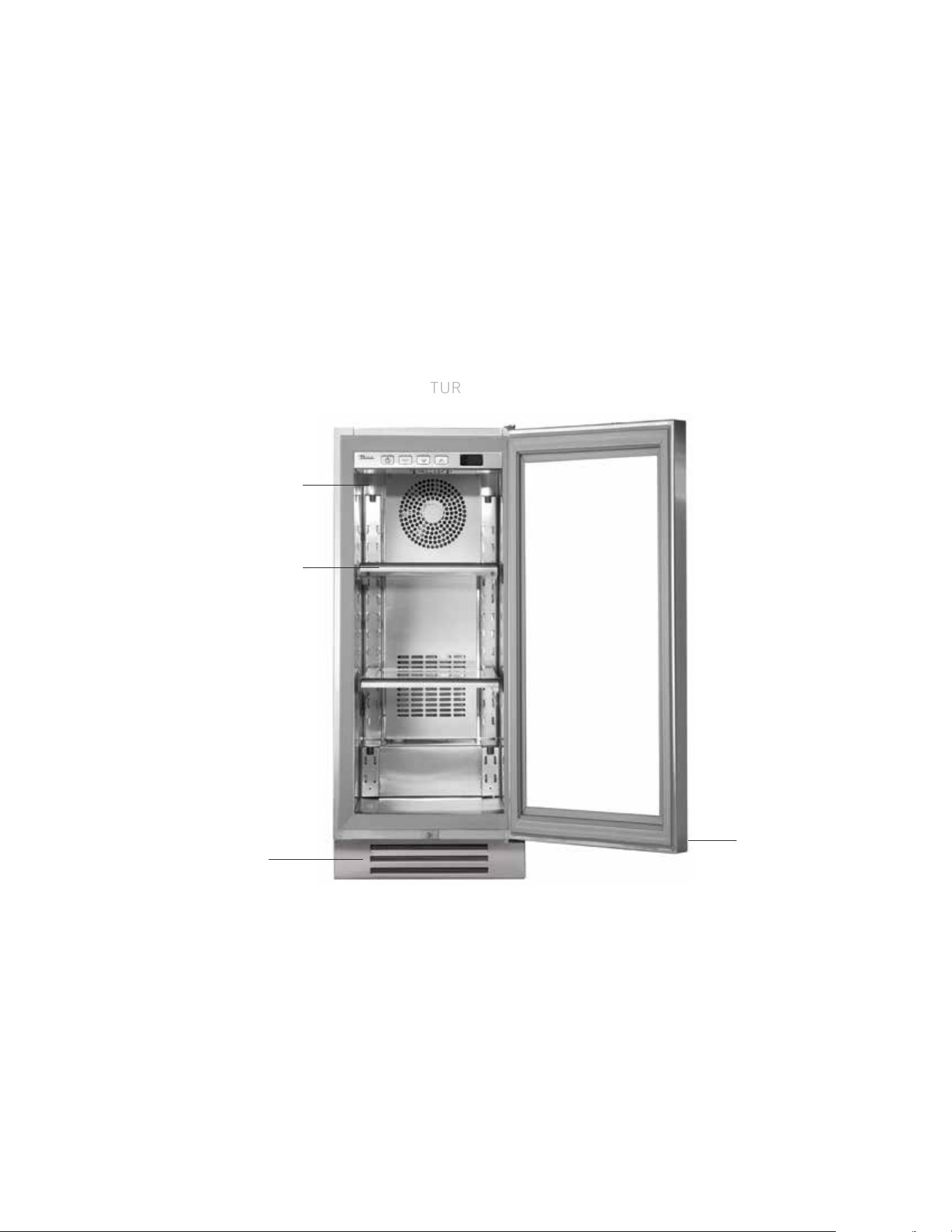
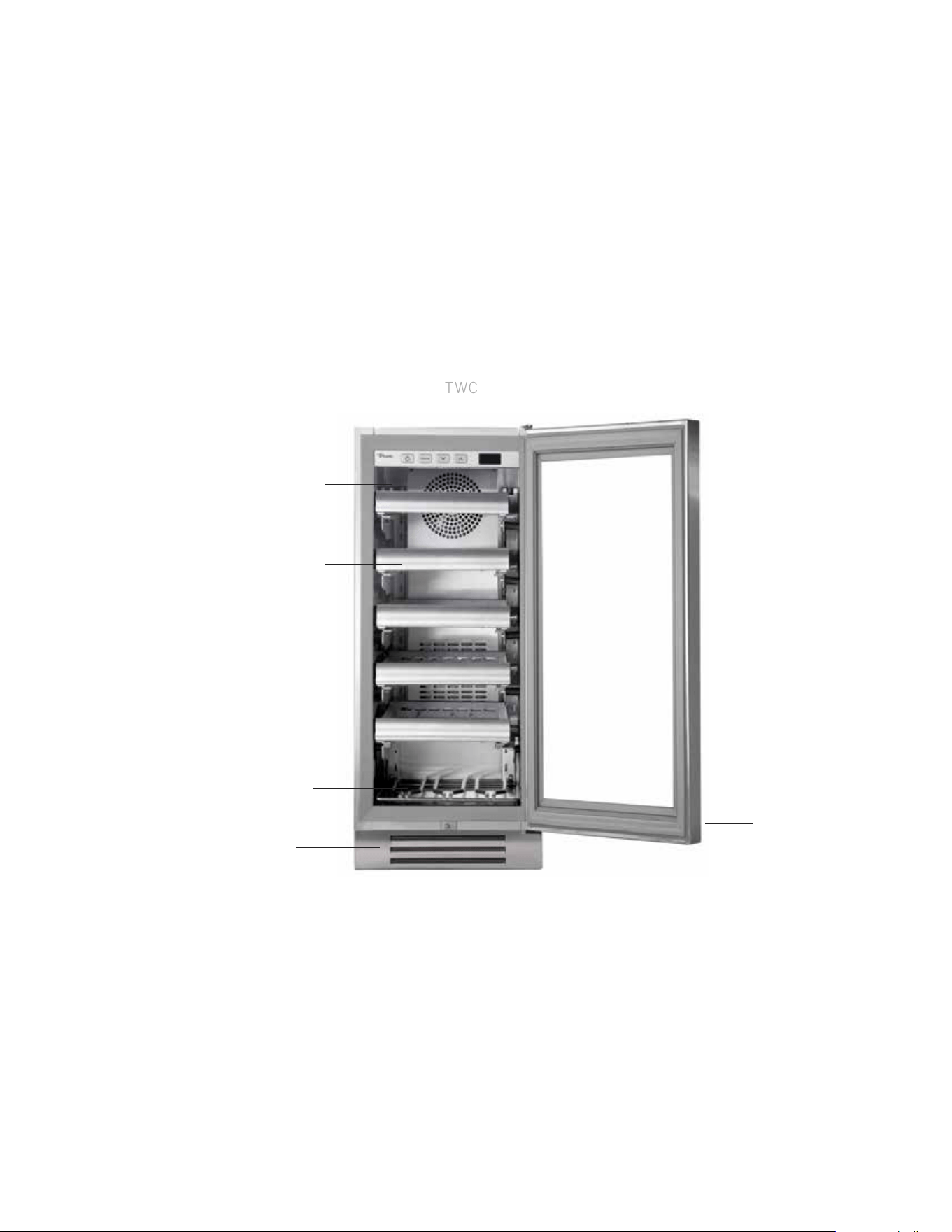
TRUE WINE CABINET COMPONENTS
TWC
LOCATION OF SERIAL TAG
REMOVABLE KICK PLATE
FOR EASY CLEANING
DOOR LOCK
ADJUSTABLE SLIDE OUT
WINE SHELVES (5)
FLOOR WINE CRADLE (1)

60
TRUE RESIDENTIAL
®
50 - 51
h O m e a l a r m s y s t e m
( D u a l z O n e w i n e c a B i n e t O n l y )
PRESERVE THE MOMENT
®
61
15 INCH & 24 INCH INSTALL GUIDE
HOME ALARM SYSTEM - DUAL ZONE WINE CABINET ONLY
Dual Zone wine units are provided with three wires located behind the kick-plate that may be connected
to a home alarm system. These connections are for low voltage, low current circuits similar to those used
as signals for alarms on doors and windows. Refer to the specifications of your alarm system to determine
the type of circuit used.
The color codes for the different circuits are as follows:
• Normally closed contacts: White with black and violet
• Normally open contacts: White with blue and black
• Common: White with black
CAUTION: ANY UNUSED TERMINALS SHOULD BE FULLY INSULATED AND ALL WIRES
SHOULD BE SECURED AWAY FROM MOVING PARTS AND SHARP EDGES.

62
TRUE RESIDENTIAL
®
s h e l v i n g a D j u s t m e n t
52 - 53
PRESERVE THE MOMENT
®
63
15 INCH & 24 INCH INSTALL GUIDE
ANTI-VIBRATION
BUMPERS
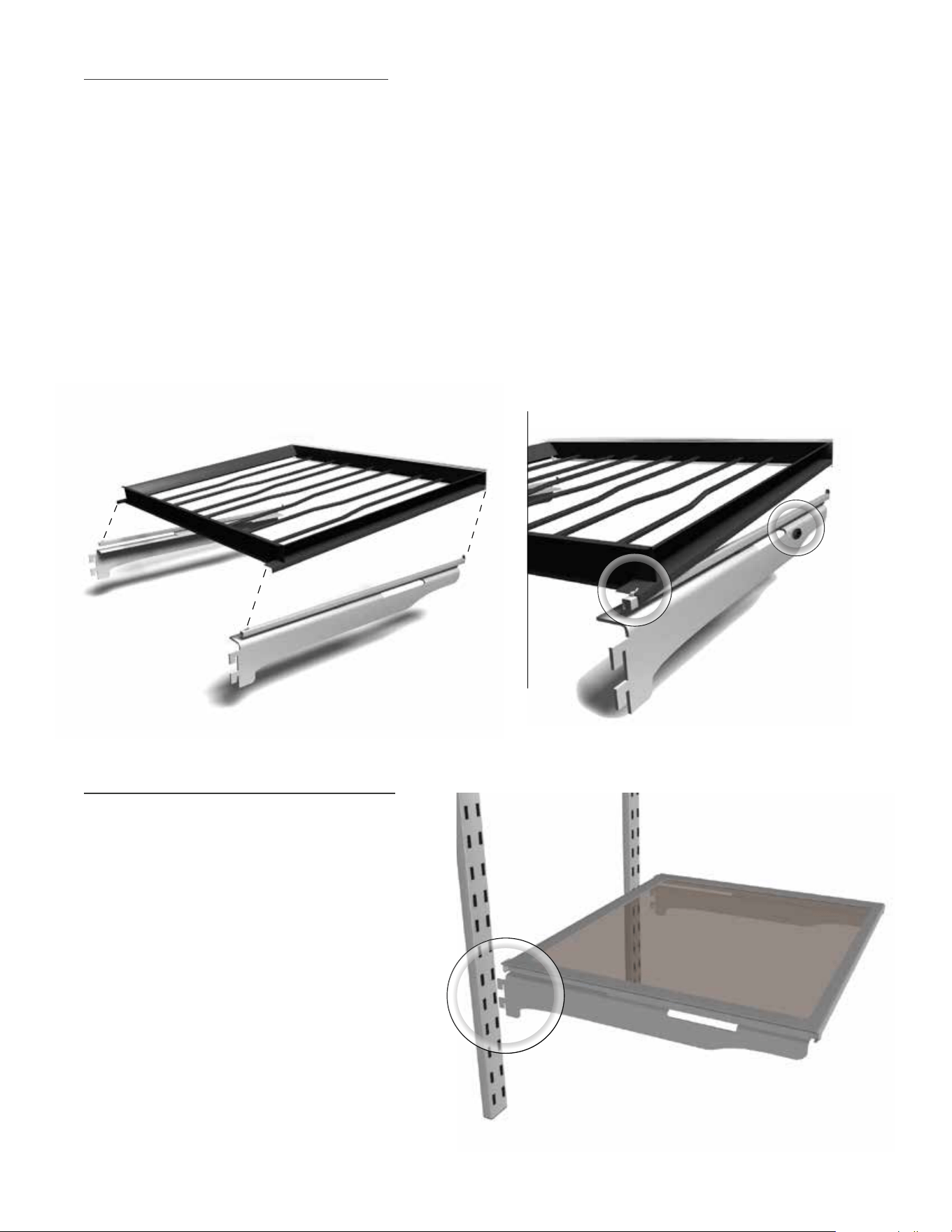
WINE SHELVING ADJUSTMENT
The glide out wine shelves in TBC, TWC and TWZ-DZ
models consist of 3 pieces. These pieces are the wire
wine rack and 2 mounting bracket/glide assemblies
(one for the hinge side and one for the non-hinge side).
To remove the wine shelf, pull up on the front of the
wine rack and it will separate from the two mounting
brackets. The two mounting brackets may now be
removed from the pilasters by lifting straight up then
pulling the brackets out of the pilasters.
NOTE WHEN REINSTALLING THE BRACKETS,
THE BRACKET WITH THE LARGER VIBRATION
BUMPER MUST BE INSTALLED ON THE SAME
SIDE OF THE CABINET AS THE DOOR HINGE.
WHEN REINSTALLING THE WINE RACK, BE
SURE THAT THE BACK OF THE RACK HOOKS
UNDERNEATH THE TAB ON THE GLIDE.
The tab on the front of the glide must also fit securely
in the gap between the handle and the rack (see
illustration). If the fit is too tight, you may need to
loosen the screws on the back of the handle to increase
the gap.
The wine shelves are held securely by the anti-vibration
bumpers. If there is too much play side-to-side, tighten
the bumpers against the compartment walls by rotating
with your fingers.
GLASS SHELVING ADJUSTMENT
The glide out glass shelves are already attached
to the mounting bracket/glide assemblies.
To install the glass shelves insert mounting
brackets into pilasters.
To remove the glass shelves, simply lift straight
up then pull the brackets out of the pilasters.

64
TRUE RESIDENTIAL
®
s t a c K i n g K i t i n s t r u c t i O n s
54 - 60
PRESERVE THE MOMENT
®
65
15 INCH & 24 INCH INSTALL GUIDE
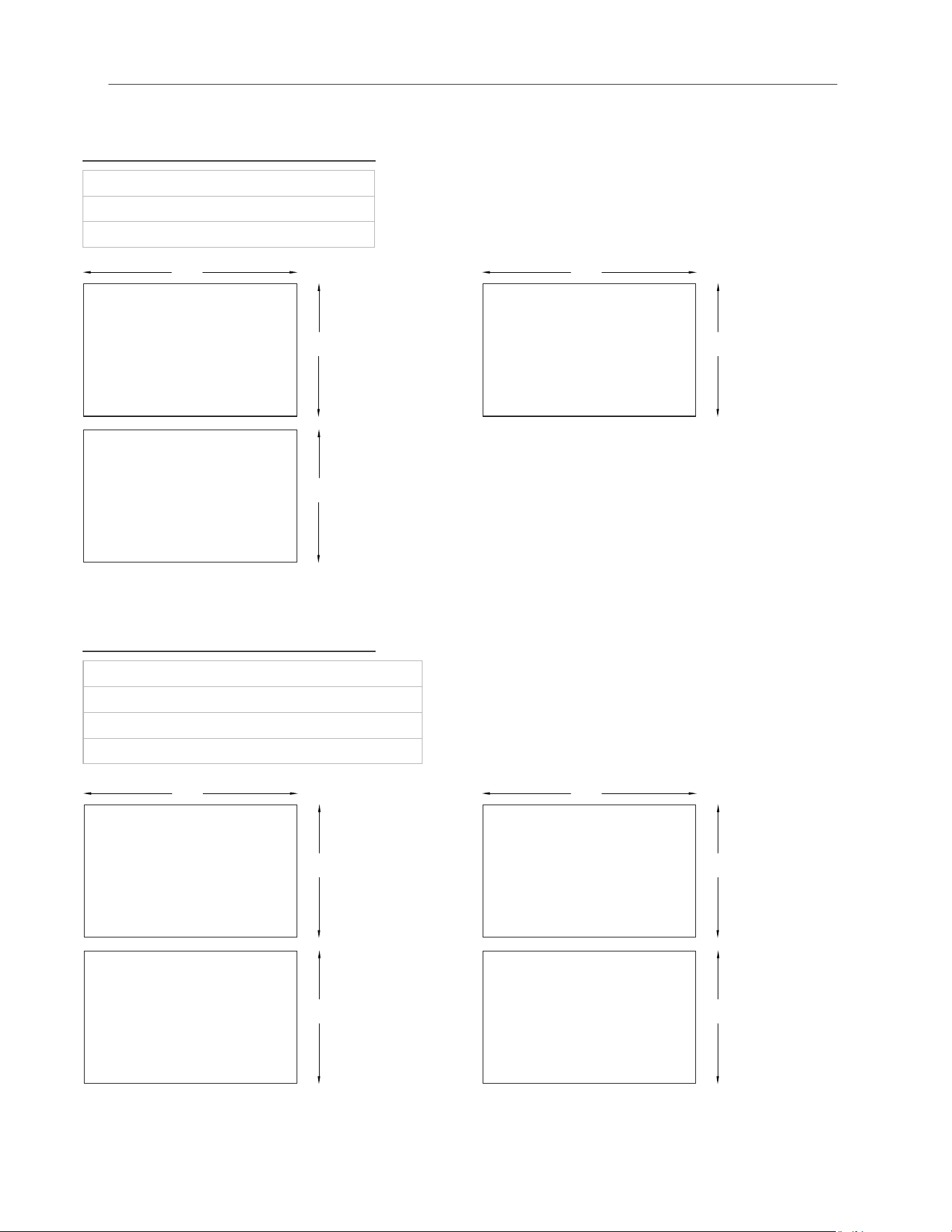
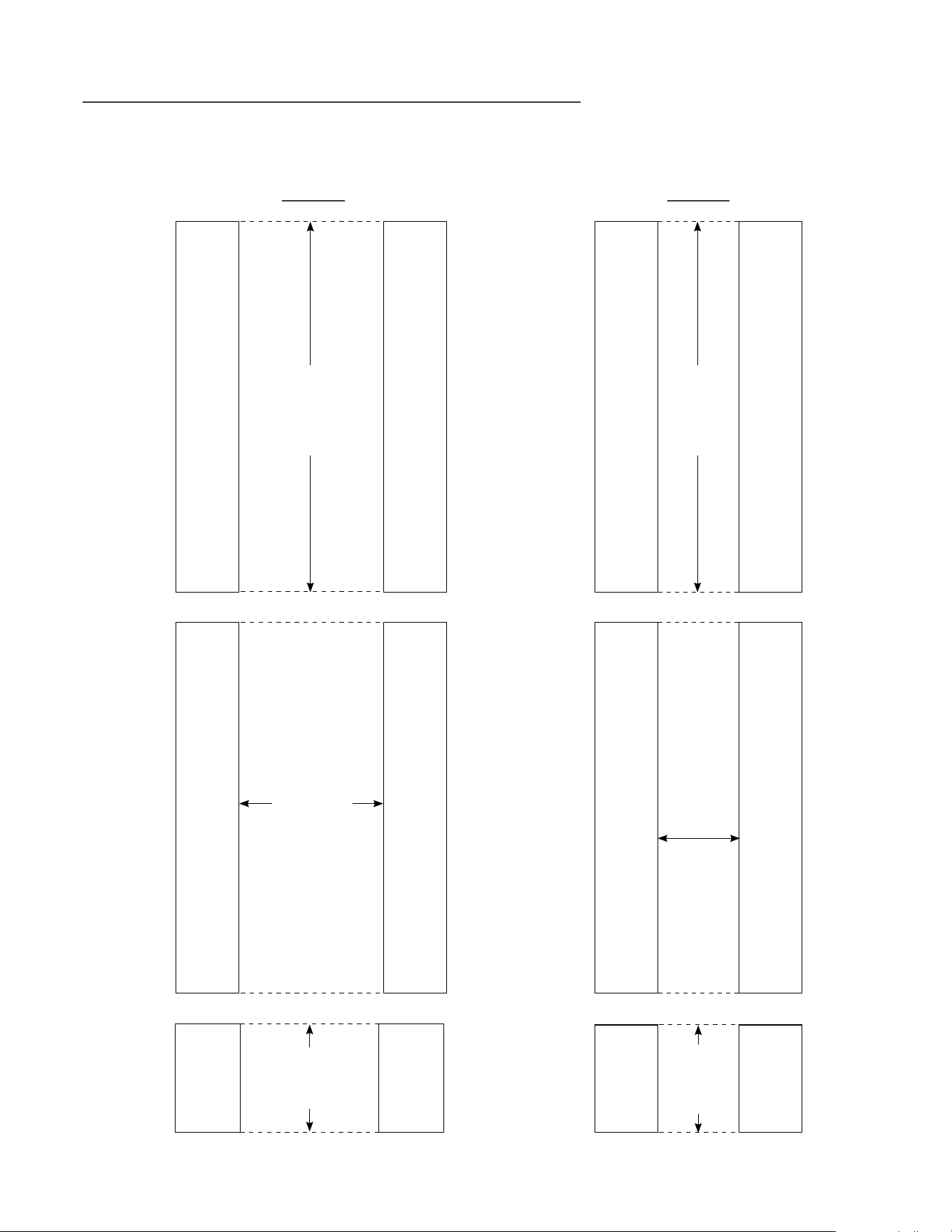
INSTALLATION SPECIFICATIONS - STACKED UNITS
(SOLID AND GLASS DOOR AND OVERLAY PANELS
True’s stacked units are designed to be inserted into a cabinet opening or free standing.
Below are recommended dimensions for rough opening.
Rough Opening
HEIGHT
69
1/2
"
Rough Opening
DEPTH
24"
Rough Opening
WIDTH
24"
24 INCH
Rough
Opening
HEIGHT
69
1/2
"
Rough
Opening
DEPTH
24"
Rough
Opening
WIDTH
15"
15 INCH
66
TRUE RESIDENTIAL
®
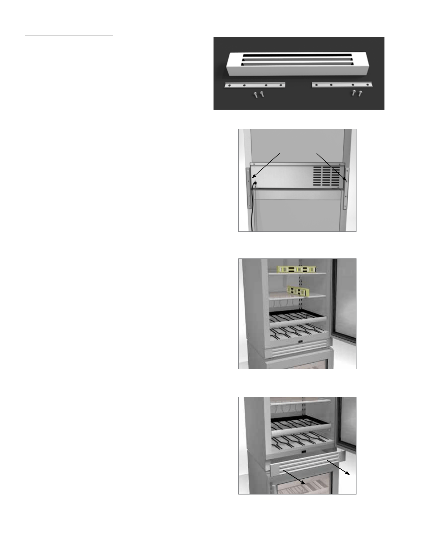
REQUIRED TOOLS:
• 1/4 inch socket and ratchet
• Level
• Floor protector
KIT:
• (1) Louver Grill
• (2) Stacking Brackets
• (4) 1/4” Hex Head Screws
1. Lay floor protectant down.
2. Uncrate cabinets and secure both shelving
and doors/drawers.
3. Install the anti-tip device per its instructions.
(Page 16).
4. Trial fit anti tip brackets using the lower
cabinet.
5. Carefully lift the top cabinet and place on
the lower cabinet. This procedure requires
assistance. Level the top cabinet.
6. Position the upper refrigerator so that it is
flush with the lower cabinet’s sides and
back.
7. Install the rear stacking brackets.
See image 1.
8. Place set in final spot. Level both top and
bottom unit. Use a level on the inside of the
cabinets. Check front to back and side to
side. See image 2.
9. Remove front grill on top cabinet. Door must
be open to remove grill. Pull both sides of
the louver grill at the same time. The grill
then snaps out. See image 3.
2
1
3
STACKING
BRACKETS
TRUE STACKING KIT
67
15 INCH & 24 INCH INSTALL GUIDE
10. Install the new louver grill on top cabinet.
NOTE: MAKE SURE ANY PLASTIC
PROTECTIVE MATERIAL IS REMOVED FROM
LOUVER GRILL BEFORE INSTALLING.
11. Door must be open for installation. Slide louver
grill into place and snap both sides into the unit. See
image 4.
12. Installation is complete.
4
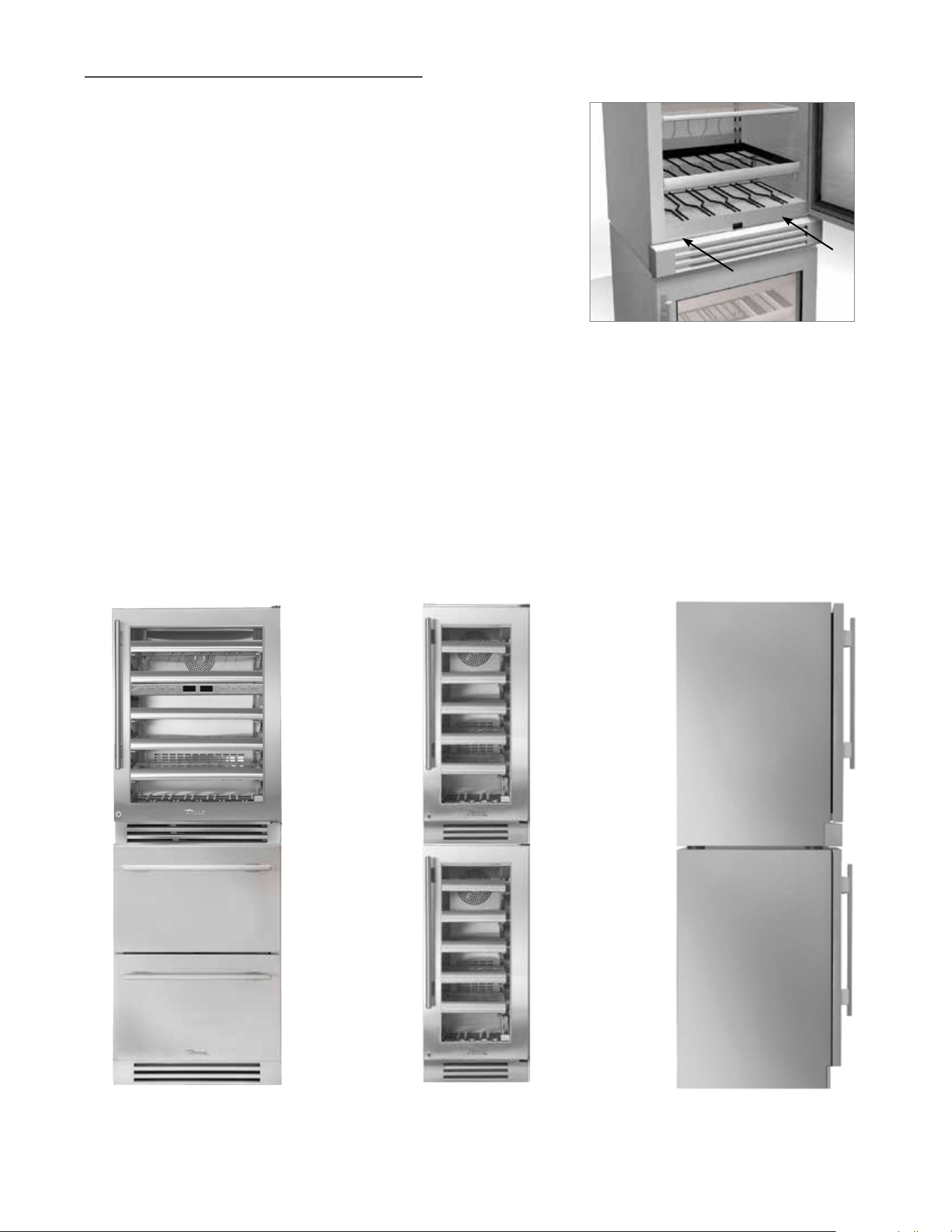
24 INCH 15 INCH 24 / 15 INCH SIDE VIEW
TRUE STACKING KIT (CONTINUED)
68
TRUE RESIDENTIAL
®
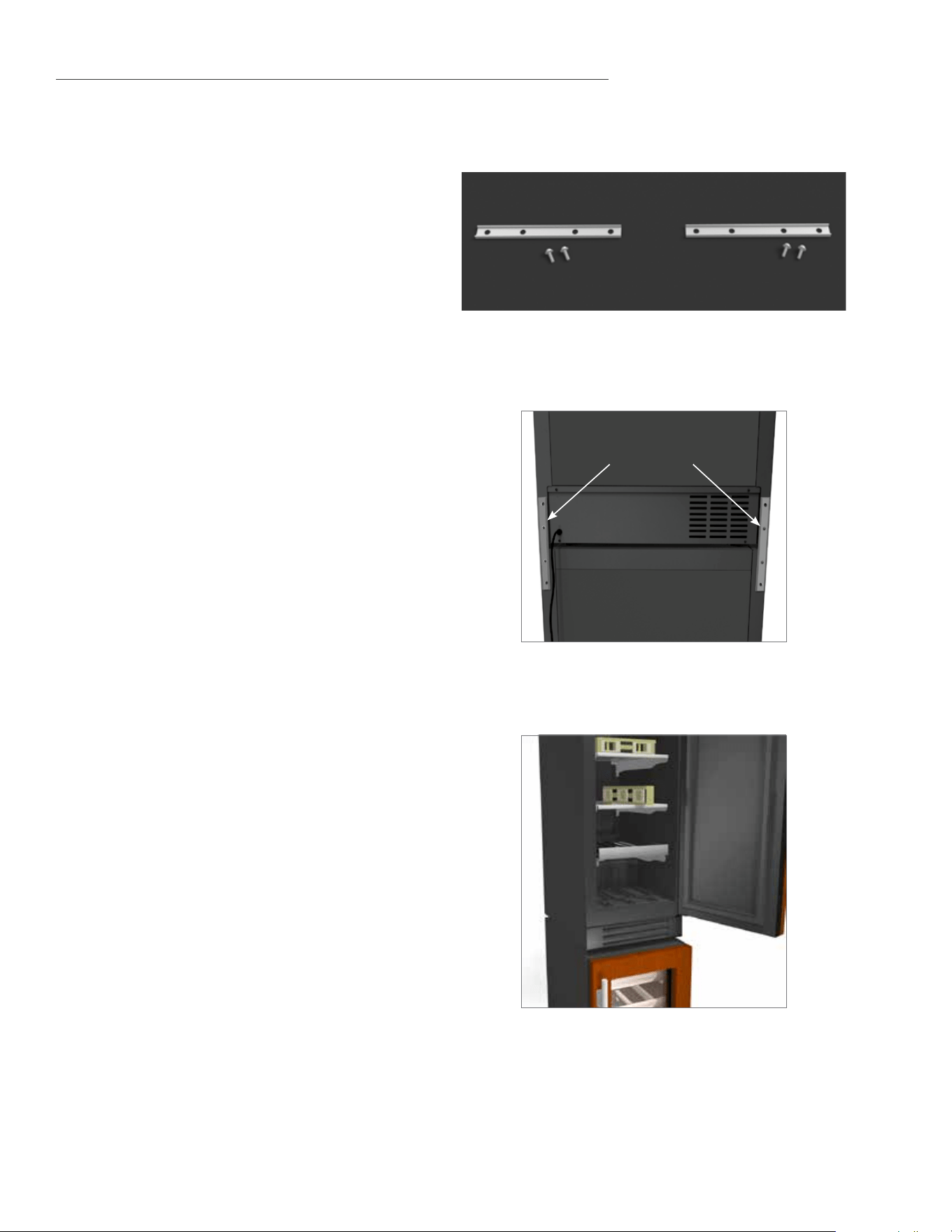
TRUE STACKING KIT FOR UNITS WITH OVERLAY PANELS
REQUIRED TOOLS:
• 1/4 inch socket and ratchet
• Level
• Floor protector
KIT:
• (2) Stacking Brackets
• (4) 1/4" Hex Head Screws
1. Lay floor protectant down.
2. Uncrate cabinets and secure both shelving
and doors/drawers.
3. Install the anti-tip device per its instructions.
(Page 16).
4. Trial fit anti tip brackets using the lower
cabinet.
5. Carefully lift the top cabinet and place on
the lower cabinet. This procedure requires
assistance. Level the top cabinet.
6. Position the upper refrigerator so that it is
flush with the lower cabinet’s sides and back.
7. Install the rear stacking brackets.
See image 1.
8. Place set in final spot. Level both top and
bottom unit. Use a level on the inside of the
cabinets. Check front to back and side to side.
See image 2.
9. Installation is complete.
2
1
STACKING
BRACKETS
69
15 INCH & 24 INCH INSTALL GUIDE
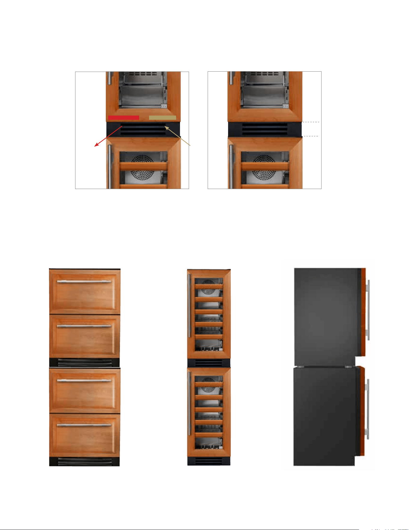
IMAGE 3
Air Flow Out Air Flow In
PLEASE NOTE WHEN ADDING A PANEL TO THE GRILL OR DOOR, AIR FLOW
NEEDS TO BE TAKEN INTO CONSIDERATION. SEE IMAGES 3 AND 4
.
IMAGE 4
Approximate distance from bottom
of door to bottom of cabinet.
3
7/16
"
24 INCH 15 INCH 24 / 15 INCH SIDE VIEW
70
TRUE RESIDENTIAL
®
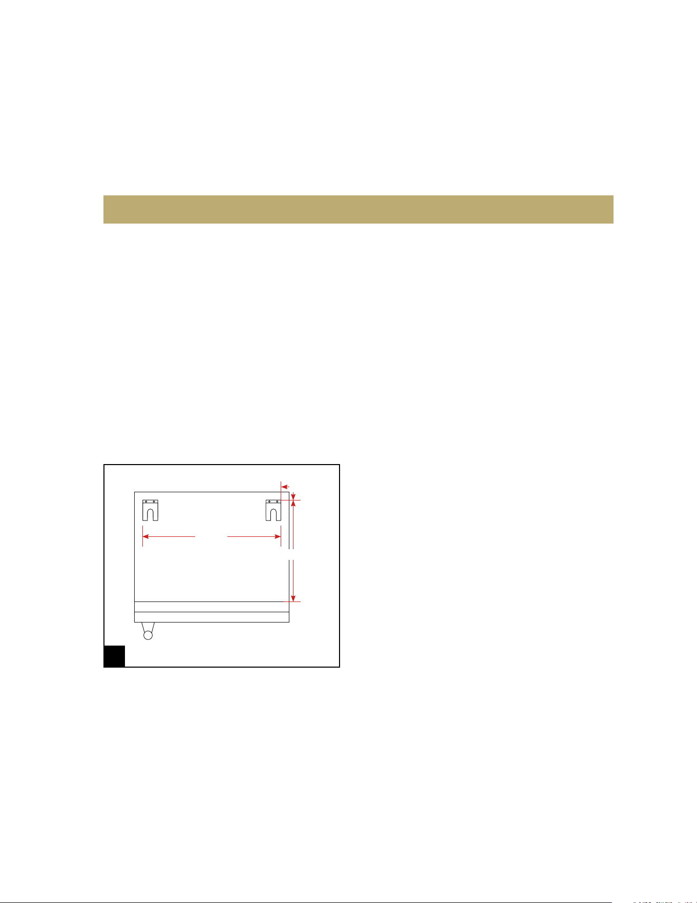
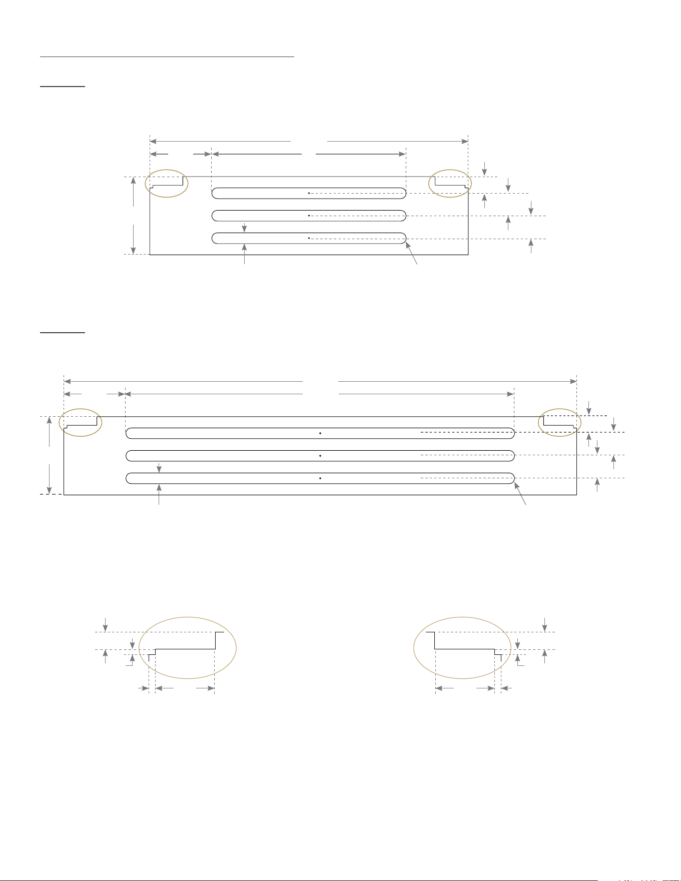
CUSTOM WOOD LOUVER TEMPLATE
15 INCH
Detail A Detail B
14
3/4
"
3
5/8
"
1
1/32
"
1
1/32
"
R1/4" (6 PLCS.)
R1/4" (6 PLCS.)
1/2" (3 PLCS.)
1/2" (3 PLCS.)
25/32
"
9"2
7/8
"
SCALE 2:3
Notch here for a
left hinged unit
DETAIL A DETAIL B
1
3/8
"
13/32
"
5/32
"
1/8
"
SCALE 2:3
Notch here for a
right hinged unit
1
3/8
"
13/32
"
5/32
"
1/8
"
24 INCH
23
3/4
"
3
5/8
"
Detail A Detail B
1
1/32
"
1
1/32
"
25/32
"
18"2
7/8
"

71
15 INCH & 24 INCH INSTALL GUIDE
s t a i n l e s s s t e e l e q u i p m e n t c a r e a n D c l e a n i n g
g e n e r a l m a i n t e n a n c e
c O n D e n s a t i O n
s e r v i c e i n f O r m a t i O n
f r e q u e n t l y a s K e D q u e s t i O n s
w a r r a n t y
61 - 67
PRESERVE THE MOMENT
®

72
TRUE RESIDENTIAL
®
CAUTION: DO NOT USE ANY STEEL WOOL,
ABRASIVE OR CHLORINE BASED PRODUCTS TO
CLEAN STAINLESS STEEL SURFACES.
STAINLESS STEEL OPPONENTS
There are three basic things which can break down
your stainless steel’s passivity layer and allow
corrosion to rear its ugly head.
1. Scratches from wire brushes, scrapers, and steel
pads are just a few examples of items that can be
abrasive to stainless steel’s surface.
2. Deposits left on your stainless steel can leave
spots. You may have hard or soft water depending
on what part of the country you live in. Hard water
can leave spots. Hard water that is heated can
leave deposits if left to sit too long. These deposits
can cause the passive layer to break down and
rust your stainless steel.
All deposits left from food prep or service should
be removed as soon as possible.
3. Chlorides are present in table salt, food, and
water. Household and industrial cleaners are the
worst type of chlorides
to use.
RECOMMENDED CLEANERS FOR CERTAIN SITUATIONS /
ENVIRONMENTS OF STAINLESS STEEL
A. Soap, ammonia and detergent medallion applied
with a cloth or sponge can be used for routine
cleaning.
B. Arcal 20, Lac-O-Nu Ecoshine applied provides
barrier film for fingerprints and smears.
C. Cameo, Talc, Zud First Impression is applied by
rubbing in the direction of the polished lines for
stubborn stains and discoloring.
D. Easy-off and De-Grease It oven aid are excellent
for removals on all finishes for grease-fatty acids,
blood and burnt-on foods.
E. Any good commercial detergent can be applied
with a sponge or cloth to remove grease and oil.
F. Benefit, Super Sheen, Sheila Shine are good for
restoration / passivation.
NOTE: THE USE OF STAINLESS STEEL
CLEANERS OR OTHER SUCH SOLVENTS IS NOT
RECOMMENDED ON PLASTIC PARTS. WARM
SOAP AND WATER WILL SUFFICE.
8 STEPS THAT CAN HELP PREVENT RUST ON STAINLESS STEEL:
1. USING THE CORRECT CLEANING TOOLS
Use non-abrasive tools when cleaning your stainless steel
products. The stainless steel’s passive layer will not be
harmed by soft cloths and plastic scouring pads. Step 2
tells you how to find the polishing marks.
2. CLEANING ALONG THE POLISH LINES
Polishing lines or “grain” are visible on some stainless
steels. Always scrub parallel to visible lines on some
stainless steels. Use a plastic scouring pad or soft cloth
when you cannot see the grain.
3. USE ALKALINE, ALKALINE CHLORINATED OR NON-
CHLORIDE CONTAINING CLEANERS
While many traditional cleaners are loaded with chlorides,
the industry is providing an ever increasing choice of non-
chloride cleaners. If you are not sure of your cleaner’s
chloride content contact your cleaner supplier. If they
tell you that your present cleaner contains chlorides,
ask if they have an alternative. Avoid cleaners containing
quaternary salts as they can attack stainless steel, causing
pitting and rusting.
4. WATER TREATMENT
To reduce deposits, soften the hard water when possible.
Installation of certain filters can remove corrosive and
distasteful elements. Salts in a properly maintained water
softener can be to your advantage. Contact a treatment
specialist if you are not sure of the proper water
treatment.
5. MAINTAINING THE CLEANLINESS OF YOUR FOOD
EQUIPMENT
Use cleaners at the recommended strength (alkaline
chlorinated or non-chloride). Avoid build-up of hard
stains by cleaning frequently. When boiling water with
your stainless steel equipment, the single most likely cause
of damage is chlorides in the water. Heating any cleaners
containing chlorides will have the same damaging effects.
6. RINSE
When using chlorinated cleaners you must rinse and wipe
dry immediately. It is better to wipe standing cleaning
agents and water as soon as possible. Allow the stainless
steel equipment to air dry. Oxygen helps maintain the
passivity film on stainless steel.
7. HYDROCHLORIC ACID (MURIATIC ACID) SHOULD NEVER
BE USED ON STAINLESS STEEL
8. REGULARLY RESTORE/PASSIVATE STAINLESS STEEL
STAINLESS STEEL EQUIPMENT CARE AND CLEANING

73
15 INCH & 24 INCH INSTALL GUIDE
GENERAL MAINTENANCE
REPLACEMENT PARTS
SERVICE DEPARTMENT
WARRANTY DEPARTMENT
Keeping the condenser coil clean will minimize required service and lower electrical cost. The condenser coil is
accessible from the front.
The condenser coil should be cleaned by removing dust and other build-up from the tube assembly with
vacuum or a cleaning rag.
When properly cleaned you should be able to see through the tube assembly.
Warranty does not cover cleaning the condenser coil.
True maintains a record of the cabinet serial number for your unit. If at any time during the life of your unit, a
part is needed, you may obtain that part by furnishing the model number and serial number to the company
from whom you purchased the cooler. For replacement parts contact the dealer from whom you purchased the
refrigerator or call True parts department at 844-849-6179. Inquires can be sent to the following address:
ATTN Parts Department
True Manufacturing
2001 East Terra Lane
O’Fallon, MO 63366-4434
Trueresidentialparts@truemfg.com
Phone Number : 844-849-6179
Support and train field service providers on True Residential Equipment. Help troubleshoot and repair service
issues in the field on True Residential products.
Phone Number : 844-746-9423
Fax : 636-980-8510
Email : service@truemfg.com
Answers questions regarding a units warranty status. Process warranty claims from service providers.
Phone Number : 844-849-6179
Fax : 636-980-8510
Email : trueresidentialwarranty@truemfg.com
Submit Claims to : warrantyclaims@truemgf.com
CONDENSATION
Leaving the door open for a long period of time or a unit that is running with little to no product inside may also
cause excessive condensation.
74
TRUE RESIDENTIAL
®
FREQUENTLY ASKED QUESTIONS
Q. HOW DO I ADJUST THE TEMPERATURE?
A. Refer to True Precision Control
®
Operation listed in Table of Contents on page 1.
Q. WHY DOES THE EVAPORATOR FAN MOTOR RUN CONSTANTLY?
A. This is a normal operation. The evaporator fan motor will run continuously to ensure even temperature
throughout your cabinet. This will only stop when the door is opened to keep warm air from being circulated
throughout the cabinet.
Q. WHY ISN’T MY UNIT COOLING PROPERLY?
A. Check to see that there are no obstructions to the condenser coil (behind front grill). Confirm that the
condenser area is clean.
Q. HOW DO I ADJUST OR REMOVE A SHELF FROM MY CURRENT CONFIGURATION?
A. Refer to Shelving Adjustment listed in Table of Contents on page 1.
Q. WHY IS THERE WARM AIR COMING FROM THE BOTTOM/FRONT OF THE REFRIGERATOR (GRILL/KICKPLATE AREA)?
A. This is normal as heat dissipation is part of the refrigeration cycle.
Q. WHY IS THERE CONDENSATION FORMING ON THE INSIDE OR OUTSIDE OF THE UNIT?
A. Leaving the door open for a long period of time or a unit that is running with little to no product inside may
also cause excessive condensation.
Q. WHAT ARE THE PRESET LIMITS FOR THE HIGH TEMPERATURE ALARM?
A. The electronic control will monitor temperatures and activate an alert if unsafe product temperatures are
present for more than 60 minutes. For single and dual zone wine cabinets, the alarm will activate at 70°F. F o r
all refrigerators, the alarm will activate at 50°F.
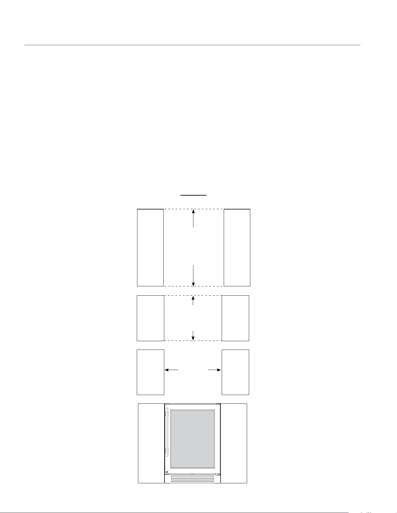
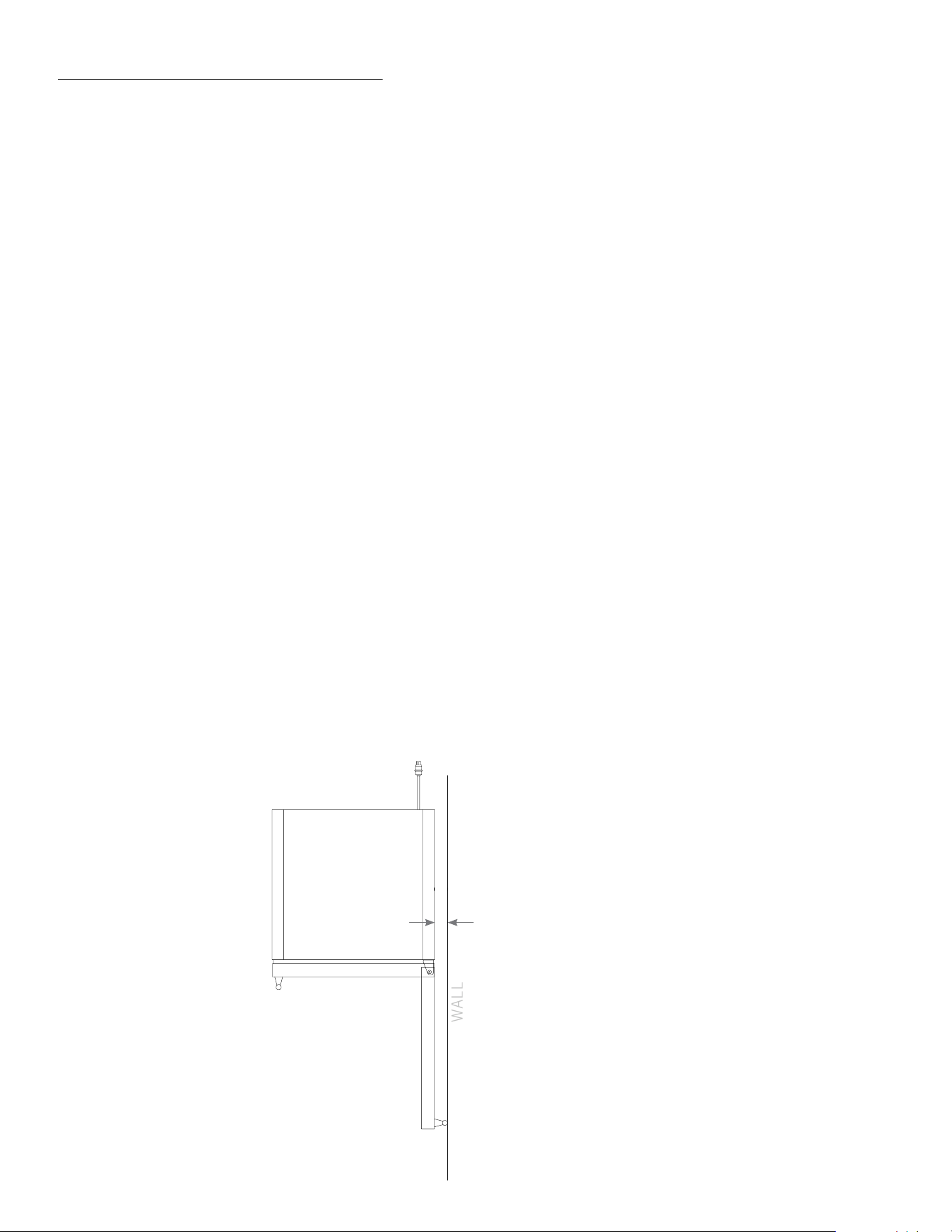
Q. HOW MUCH DISTANCE IS NEEDED FROM THE WALL TO HAVE THE HINGE ON THE WALL SIDE AND STILL OPEN 90 DEGREES?
A. 2 inches
1
7/8
"
WALL

75
15 INCH & 24 INCH INSTALL GUIDE
Q. CAN I PUT 2 UNITS FLUSH AGAINST EACH OTHER WITHOUT SPACING?
A. Yes, usually. In typical climate controlled temperature/humidity conditions our units can be installed flush
against each other. However, if you place your units in a humid, non-climate controlled area, ½ to 1 inch of
spacing between the units will help prevent potential condensation buildup.
Q. DOES TRUE SELL THE WOOD DOORS ON OVERLAY?
A. No, for wood front doors, reach out to your cabinet maker and provide them with the overlay template
available on the right hand side of our document library:
http://www.true-residential.com/Support/Document-Library/
Q. DOES THE OVERLAY COME WITH THE HANDLE?
A. No, our handle can be ordered as an accessory, or any pull can be added to your overlay drawer.
Q. DO TRUE UNITS HAVE A ZERO CLEARANCE HINGE?
A. Yes. No spacing is needed on the either side of our unit. It can be placed flush with adjoining cabinetry and
still open fully.
Q. WHY DOESN’T THE WARRANTY COVER COMMERCIAL UNITS IN MY HOME?
A. Due to Department of Energy regulations on refrigerator energy use, we are not able to market and sell our
commercial units in homes. Providing a warranty to home users is included in this.
Q. WHAT IS THE DECIBEL RATING OF THE UNITS?
A. 42-47 db.
Q. HOW DO I CHANGE THE LIGHTING?
A. For models that include a color button, simply push the button until the desired color appears.
• For 15 inch models without a color button press + at the same time until your desired
color is reached.
• On 24 inch dual zone models press + .
Q. MY DISPLAY WAS READING “REF” WHAT DOES THAT MEAN?
A. The REF code is shown when the cabinet doesn’t reach the desired set temp in the allotted time. The
problem may be that the door was left open or very hot product was loaded into the unit. To reset the code,
simply power off, and power on the refrigerator. If the code returns, please contact True for service.
Q. I DON’T SEE A SERVICE COMPANY IN MY AREA, WHO CAN I CALL?
A. Please call True’s service line: 888.616.8783 or email us: info@true-residential.com to have us help find an
appropriate servicer for your cabinet.
Q. DOES MY REFRIGERATOR HAVE TO BE COVERED OUTDOORS?
A. No. All True undercounter are UL rated for outdoor use.
True units are able to be installed free standing. If left exposed to the elements throughout winter months, a
cover will help preserve the life and beauty of your True product.
Please note: The gaskets do not provide a water tight seal, so it is recommended that the unit is installed so
that the countertop of your outdoor kitchen covers the door or drawer gasket.
Q. WHAT SHOULD I DO IN THE WINTER? DO I HAVE TO BRING IT IN? HOW COLD CAN IT GET BEFORE IT’S A PROBLEM?
A. In regions with cold winters (consistently below 32ºF), True refrigerators should be turned to off, and
emptied of all contents. If exposed to the elements, covering your cooler will extend its life and beauty.
76
TRUE RESIDENTIAL
®
BEVERAGE DISPENSER QUESTIONS
Q. WHAT TYPE OF TAP SYSTEM CAN BE USED WITH A TRUE UNIT?
A. Different tap systems can be used on ¼ barrel short kegs, but low profile taps are not available in the non-
sankey variety, and therefore will probably not fit in our dispensers when used with tall kegs.
Q. WHERE CAN I GET MY CO
2
TANK FILLED?
A. C0
2
is available at many sporting good stores as well as paintball stores. C0
2
canisters can often be
exchanged (much like propane tanks) at many liquor stores as well as nationally at AIRGAS locations.
WINE CABINET QUESTIONS
Q. CAN I STORE MAGNUM BOTTLES?
A. Magnums will fit on our floor rack which holds 5 bottles. Also, our shelves are removable to create additional
space.
Q. CAN I STORE PINOT/BORDEAUX/RIESLING BOTTLES?
A. Yes. Almost all bottle varieties will fit in your True Wine Cabinet.
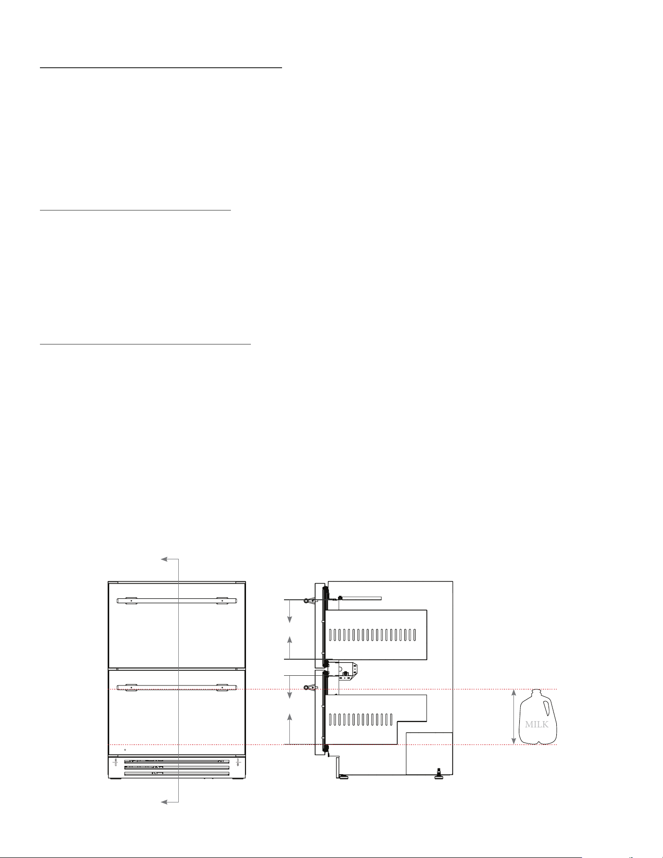
DRAWER CABINET QUESTIONS
Q. HOW TALL ARE THE DRAWERS? CAN I STORE AN UPRIGHT BOTTLE OF WINE, OR A GALLON OF MILK?
11
25/32
"
10
9/32
"
A
A
Scale 1 : 8
10
"
MILK

77
15 INCH & 24 INCH INSTALL GUIDE
LIMITED 30 DAY COSMETIC WARRANTY
Stainless steel doors, handles, and shelves are warranted to be free from defective materials or workmanship for a period of thirty (30)
days from the date of original retail purchase. Any defects must be reported to the selling dealer within thirty (30) days from the date of
original retail purchase. This limited warranty excludes any type of freight / concealed damage.
THREE-YEAR PARTS & LABOR WARRANTY *For units purchased after Feb 1, 2013.
TRUE warrants to the original purchaser of every new TRUE refrigerated unit, the cabinet and all parts thereof, to be free from defects in
material or workmanship under normal and proper use and maintenance as specified by TRUE and upon proper installation and start-up
in accordance with the instruction packet supplied with each TRUE unit. TRUE’s obligation under this warranty is limited to a period of
three (3) years from the date of original installation or thirty nine (39) months after shipment date from TRUE, whichever occurs first.
SIX-YEAR SEALED SYSTEM WARRANTY - PARTS & LABOR *For units purchased after Feb 1, 2013.
TRUE warrants its hermetically sealed system: compressor, evaporator coil, condenser coil, drier, metering device and connecting tubing
to be free from defects in both material and workmanship under normal and proper use and maintenance service for a period of six (6)
years from the date of original installation but not to exceed six (6) years and three (3) months after shipment from the manufacturer,
whichever occurs first.
SEVEN THROUGH TWELVE-YEAR SEALED SYSTEM WARRANTY - PARTS ONLY *For units shipped from True after Feb 1, 2017
and REGISTERED via True’s Product Registration Page – TRUE warrants its hermetically sealed system: compressor, evaporator coil,
condenser coil, drier, metering device and connecting tubing to be free from defects in both material and workmanship under normal
and proper use and maintenance service period of Twelve (12) years from the date of original installation but not to exceed twelve (12)
years and three (3) months after shipment from the manufacturer, whichever occurs first. Product must be registered with True to qualify
for this warranty. Factory seconds and clear Ice machines are excluded from this warranty.
TERMS APPLICABLE TO EACH WARRANTY
Any part covered under the above warranties that is determined by TRUE to have been defective within the time frame is limited to the
repair or replacement, including labor charges, of defective parts or assemblies. The labor warranty shall include standard straight time
labor charges only and reasonable travel time, as determined by TRUE.
WARRANTY CLAIMS
All claims for labor or parts must be made directly through TRUE. All claims should include: model number and serial number of
cabinet, proof of purchase, and date of installation. In case of warranted compressor, the compressor model tag must be returned to
TRUE along with the above listed information.
WHAT IS NOT COVERED BY THIS WARRANTY
TRUE’s sole obligation under this warranty is limited to either repair or replacement of parts, subject to the additional limitations below.
This warranty neither assumes nor authorizes any person to assume obligations other than those expressly covered by this warranty.
NO CONSEQUENTIAL DAMAGES. TRUE is not responsible for economic loss, profit loss; or special, indirect or consequential
damages, including without limitation, losses or damages arising from food or product spoilage claims whether or not on account or
refrigeration failure.
WARRANTY IS NOT TRANSFERABLE. This warranty is not assignable and applies only in favor of the original purchaser/user to whom
delivered. Any such assignment or transfer shall void the warranties herein made and shall void all warranties, express or implied,
including any warranty or merchantability or fitness for a particular purpose.
IMPROPER USAGE. TRUE assumes no liability for parts or labor coverage for component failure or other damages resulting from
improper usage or installation or failure to clean and/or maintain product as set forth in the warranty packet provided with the unit.
ALTERATION OR NEGLECT. TRUE is not responsible for the repair or replacement of any parts that TRUE determines have been
subjected after the date of manufacture to alteration, neglect, abuse, misuse, accident, damage during transit or installation, fire, flood,
or act of God.
IMPROPER ELECTRICAL CONNECTIONS. TRUE is not responsible for the repair or replacement of failed or damaged components
resulting from electrical power failure, high or low voltage, use of extension cords, or improper grounding of the unit.
YOUR RIGHTS UNDER STATE LAW.
This warranty gives you specific legal rights and you may have other rights that vary from state to state. Some states do not allow
the exclusion or limitation of consequential damages or a limitation on how long an implied warranty lasts, so the above exclusion or
limitation may not apply to you.
OUTSIDE U.S./CANADA. This warranty does not apply to, and TRUE is not responsible for, any warranty claims made on products sold
or used outside the United States or Canada.
SUBMIT WARRANTY CLAIMS TO: True Residential
2001 East Terra Lane
O’Fallon MO 63366
TrueResidentialW[email protected]
TRUE RESIDENTIAL
®
SERIES
LIMITED WARRANTY STATEMENT
MS • 5/17 • API2335

78
TRUE RESIDENTIAL
®
NOTES

79
15 INCH & 24 INCH INSTALL GUIDE
NOTES

80
TRUE RESIDENTIAL LINE
NOTES


CONTACT US
www.true-residential.com
(636)240-2400 • toll free (888)616-8783
SD · 12.18 · 250 · WP-XXX
975557

