

2N® Clip User Manual
2 / 75
•
•
•
•
•
•
•
•
•
•
•
•
•
•
•
•
•
•
•
•
•
•
•
•
•
•
•
•
•
•
•
Obsah:
1. Product Description
1.1 Basic Features
1.2 Main Units and Accessories
1.3 Terms and Symbols Used
1.4 Safety Precautions
2. Device Description
3. Mechanical Installation
3.1 Installation Conditions
3.2 On-Wall Installation
3.3 Stand Installation
3.4 Device Removal
3.5 Power Supply
4. Quick Guide
4.1 Device Configuration Interface Access
4.2 IP Address Retrieval
4.3 Firmware Update
4.4 Device Restart
4.4 Factory Default Reset
5. Configuration
5.1 Basic Configuration Using Hardware
5.2 Software Configuration
5.3 Used Ports
6. Device Control
6.1 Button Functions
6.2 Home Screen
6.3 Operational Statuses
7. Maintenance - Cleaning
8. Technical Parameters
9. Supplementary Information
9.1 Troubleshooting
9.2 Directives, Laws and Regulations - General Instructions and Cautions

2N® Clip User Manual
3 / 75
•
•
•
•
•
•
•
•
•
•
•
•
•
•
•
1. Product Description
In this section, we introduce the 2N
®
Clip product, outline its application options and highlight
the advantages following from its use. The section also includes safety precautions.
1.1 Basic Features
1.2 Main Units and Accessories
1.3 Terms and Symbols Used
1.4 Safety Precautions
1.1 Basic Features
2N
®
Clip is an indoor IP/SIP unit providing audio/video communication with the 2N IP intercoms.
The device includes a three-button control panel, Speakerphone, high-quality microphone with
excellent audibility and intelligibility properties, Ethernet LAN interface and external power
supply and doorbell connectors.2N
®
Clip is a top-quality, cost efficient and easy to install and
configure indoor answering unit. One installation can combine variable answering units
manufactured by 2N Telekomunikace a.s.
2N
®
Clip is equipped with a web administrator interface of its own, which provides enhanced
user comfort and security during use.
Basic properties of2N
®
Clip:
2 mm thick Plexiglass display
LAN interface with PoE supply option,
easy flush mounting,
the device can be combined in installations with the 2N
®
IndoorTouch, 2N
®
IndoorCompactand 2N
®
IndoorTalk answering units,
remote administration and configuration via 2N
®
RemoteConfiguration,
device lock,
remote door lock control
time display,
integrated administrator web interface,
integrated induction loop version option,
external doorbell button input.
2N® Clip User Manual
4 / 75
•
•
•
•
•
•
•
•
•
1.2 Main Units and Accessories
2N
®
Clip Indoor Units
Part No.
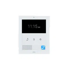
9138511
2N
®
Clip
An indoor IP/SIP unit providing audio and video communication with the
2NIP intercoms
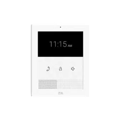
Part No.
9138512
2N
®
Clip with induction loop
An indoor IP/SIP unit providing audio and video communication with the
2NIP intercoms
Integrated induction loop
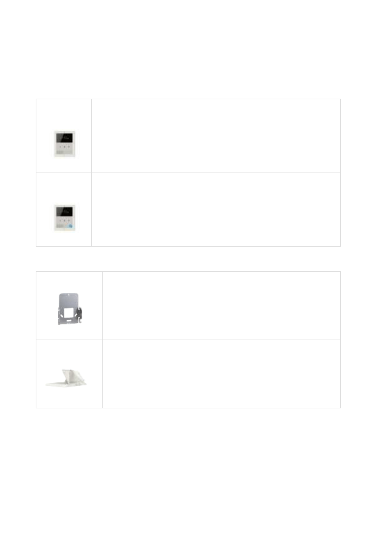
Mounting Accessories
Part No.
9138003
US mounting metal holder for 2N
®
Clip
Not included in the package of 2N
®
Clip
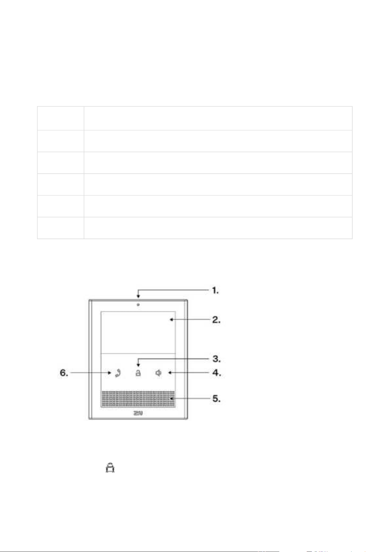
Part No. 9138002
2N
®
Clip stand
Not included in the package of2N
®
Clip

2N® Clip User Manual
5 / 75
•
•
•
•
•
•
•
1.3 Terms and Symbols Used
The following symbols and pictograms are used in the manual:
1.4 Safety Precautions
The manufacturer reserves the right to modify the product in order to improve its qualities. The
manufacturer continuously responds to the clients' requirements by improving the software.
Refer to the
2N.com company websites for the latest 2N
®
Clip firmware and User Manual.
Where necessary, the device can be installed at a safe distance from the prohibited area
and an Ethernet cable can only be carried to the required site.
Install the device out of reach of sensitive devices and human bodies as it emits
electromagnetic interference.
Refer to
Technical Parameters for the allowed range of working temperatures.
The device may not be operated at places exposed to direct sunlight or near heat sources.
The device is designed for indoor use. It may not be exposed to rain, flowing water,
condensing moisture, fog, etc.
The device may not be exposed to aggressive gas, acid vapors, solvents, etc.
It is designed for LAN connection.
•
Safety
Always abide by this information to prevent persons from injury.
•
Warning
Always abide by this information to prevent damage to the device.
•
Caution
Important informationfor system functionality.
•
Tip
Useful informationfor quick and efficient functionality.
•
Note
Routines or advice for efficient use of the device.

2N® Clip User Manual
6 / 75
Caution
This product and its installation and configuration techniques are not intended for
persons with diminished physical, sensory or mental capacities or persons with limited
experience and knowledge unless expertly supervised or duly advised as to the use of
this product by a person responsible for their safety.
2N® Clip User Manual
7 / 75
1.
2.
3.
2. Device Description
This subsection provides the product package content and description of the device elements.
Please check the product delivery before installation. Contents:
1x
2N
®
Clip
1x Certificate of ownership
1x Quick Start manual
1x metal holder for EU
2x holder fitting screws
1x doorbell connection terminal (removable)
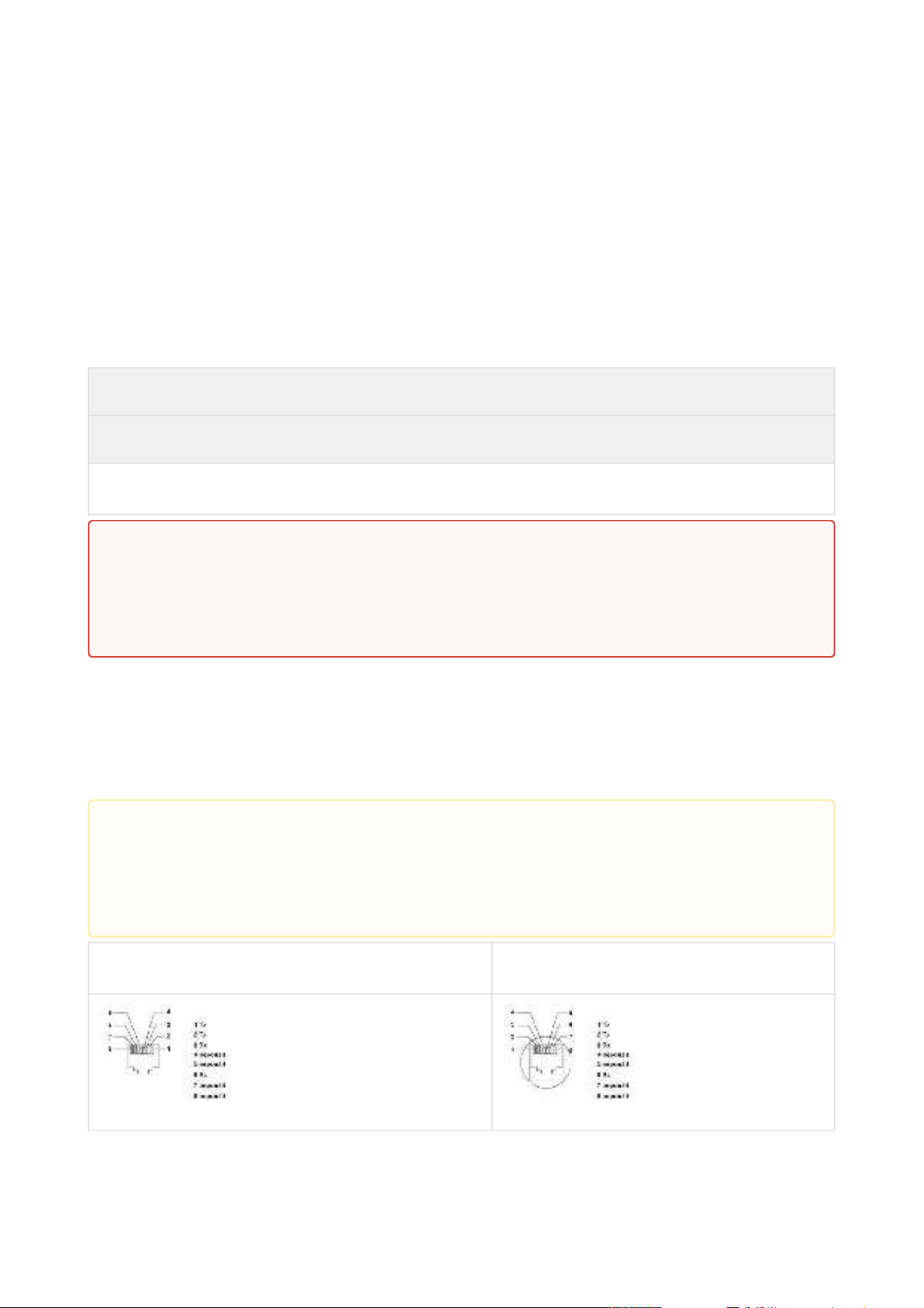
Front Layout
Microphone
Display
Lock button –
2N® Clip User Manual
8 / 75
4.
5.
6.
1.
2.
3.
4.
5.
Speaker button –
Speaker
Earphone button –
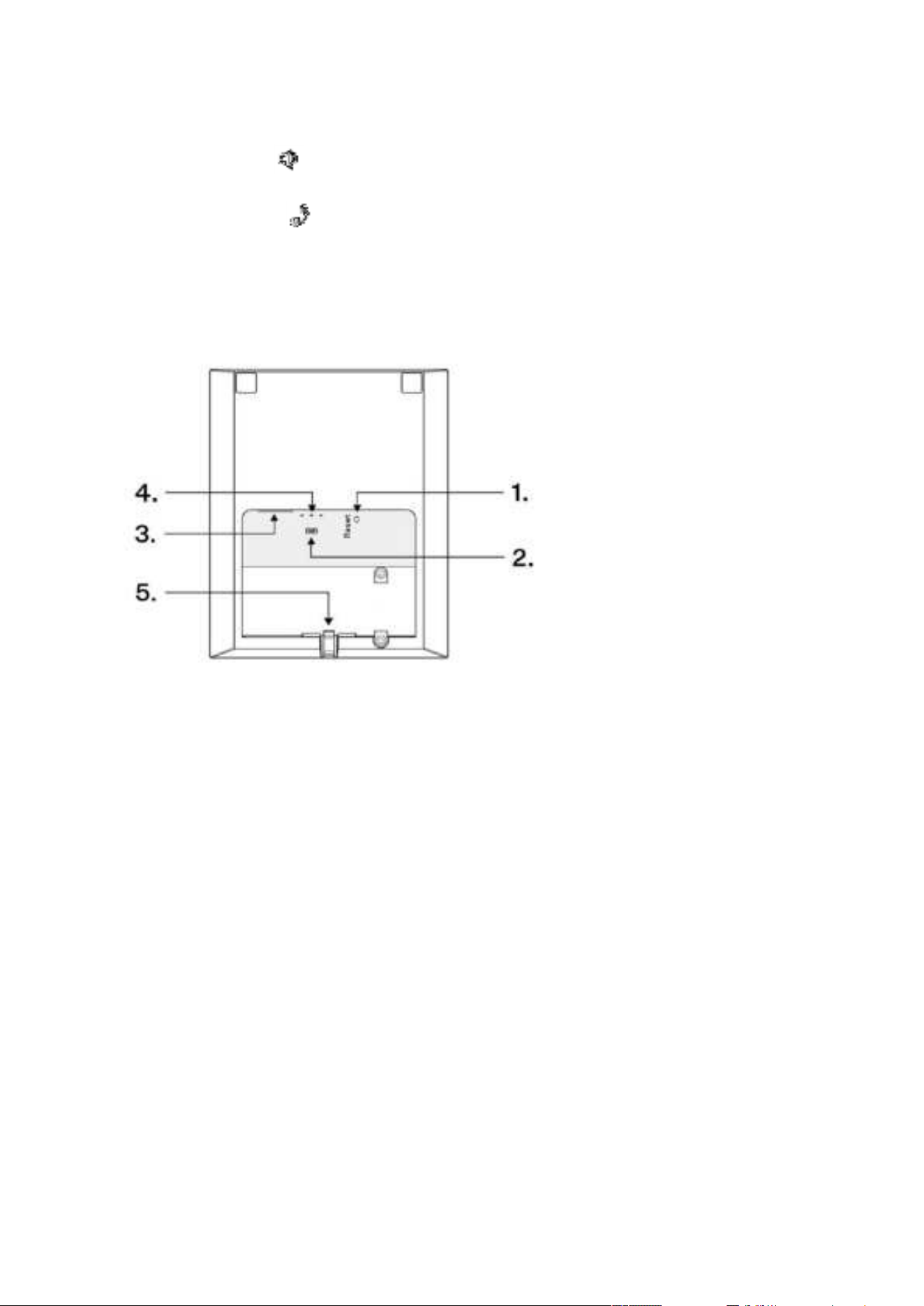
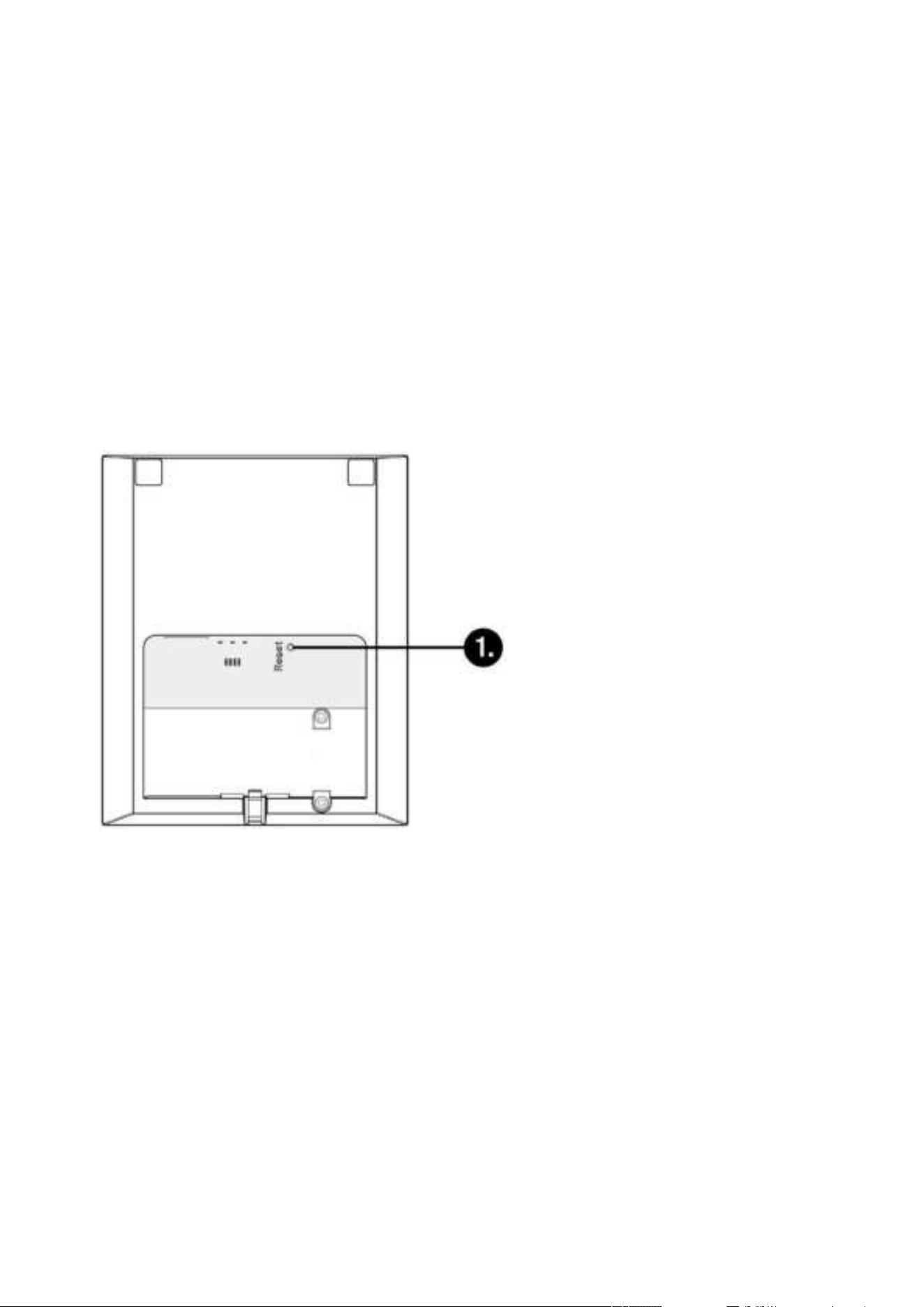
Backside Layout
RESET Button
Doorbell button input
LAN Ethernet/POE
Status LEDs
Locking latch
2N® Clip User Manual
9 / 75
•
•
•
•
•
•
•
•
3. Mechanical Installation
This section provides instructions for a proper installation and connection of 2N
®
Clip.
The device can be installed in one of the following ways:
onto a wall using a KU68 mounting box (not included in the package),
onto a wall using a metal holder,
into a stand.
3.1 Installation Conditions
3.2 On-Wall Installation
3.3 Stand Installation
3.4 Device Removal
3.5 Power Supply
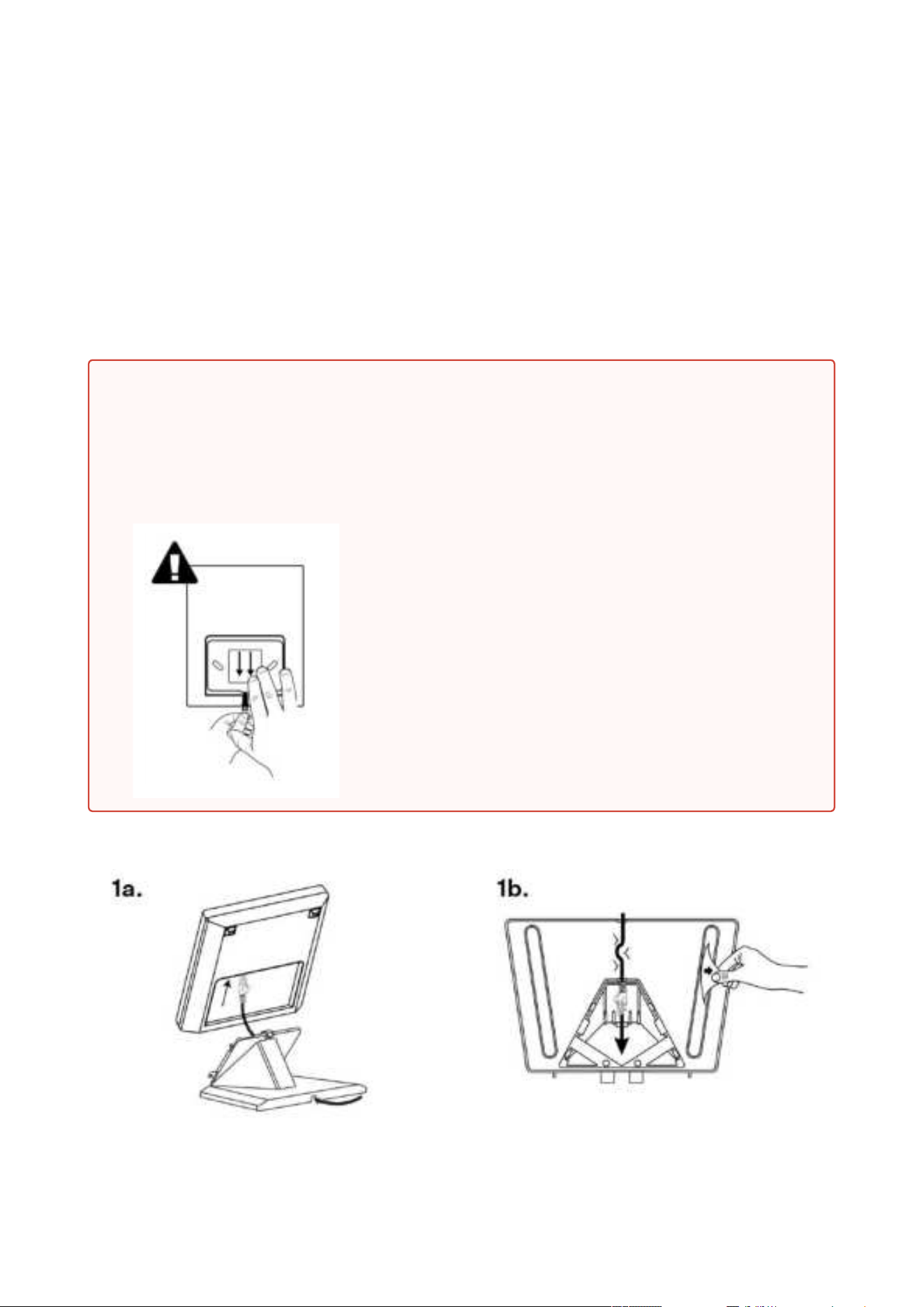
1.
2.
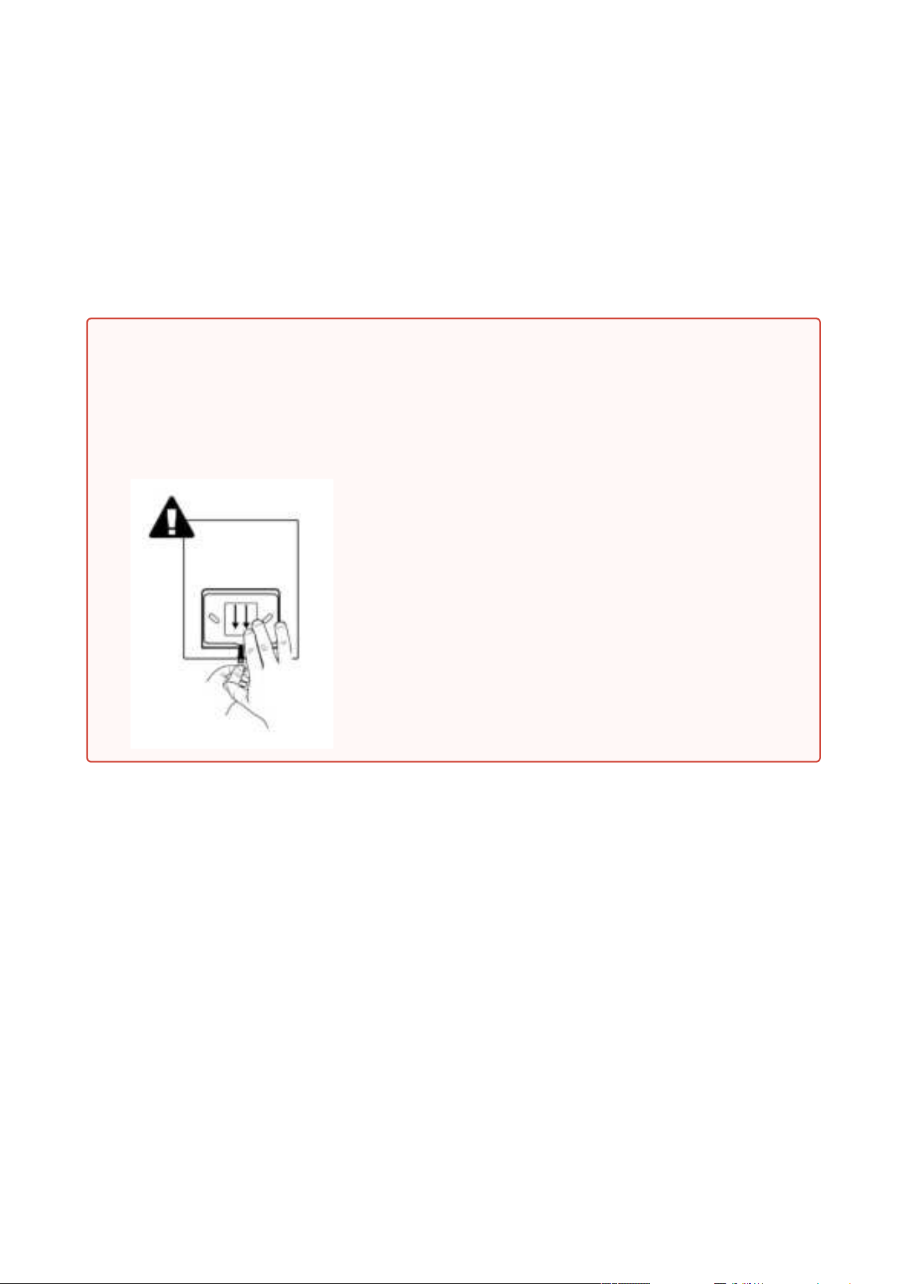
Warning
Having unpacked 2N
®
Clip, remove the metal holder for installation. Use both your
hands at the same time to remove it safely. A careless removal and insufficient push
might lead to a locking latch damage. Hence, follow the mentioned metal holder
instructions below closely!
Push the locking latch in the center of the device
bottom edge with your left hand in such a manner that
it bends sufficiently for the metal holder removal. Do
not push the locking latch from the top. You might get
injured while removing the metal holder.
Grasp the metal holder with your right hand and slide it
downwards for removal.

2N® Clip User Manual
10 / 75
•
•
•
•
•
•
•
•
•
•
•
•
•
•
3.1 Installation Conditions
Make sure that the following2N
®
Clip installation conditions are met:
There must be enough space for the device installation.
The device is designed for vertical wall mounting (perpendicular to the floor) in the height
of up to 120 cm above the floor.If necessary, operate the device in a position other than as
aforementioned for a short time only, for quick testing purposes in a servicing center, for
example.
Exceeding the allowed operating temperature may not affect the device immediately but
leads to premature ageing and lower reliability. For the acceptable range of operating
temperatures and relative humidity values refer to
8. Technické parametry.
The device is not designed for environments with increased vibrations such as means of
transport, machine rooms and so on.
The device is not intended for dusty environments and places with unstable humidity and
abrupt temperature changes.
Thedevice may not be exposed to aggressive gas, acid vapors, solvents, etc.
The device is not intended for direct connection into the Internet/WAN.
The device must be connected to the Internet/WAN via a separating active network
element (switch/router).
The device is designed for indoor use. It may not be exposed to rain, flowing water,
condensing moisture, fog, etc.
The device cannot be operated on places exposed to direct sunshine and near heat
sources.
Keep some free space above and below the device to allow air to flow and conduct heat
away.
No strong electromagnetic radiance is allowed on the installation site.
Make sure that the VoIP connection is configured properly according to the SIP and other
VoIP recommendations.
It is recommended that the power adapter be connected to the mains via a UPS and
reliable overvoltage protection.
2N® Clip User Manual
11 / 75
•
3.2 On-Wall Installation
For on-wall mounting, install the flush mounting box first into which the device is subsequently
mounted.
Here is what you can find in this section:
3.2.1 Flush Mounting Box Installation of Device
1.
2.
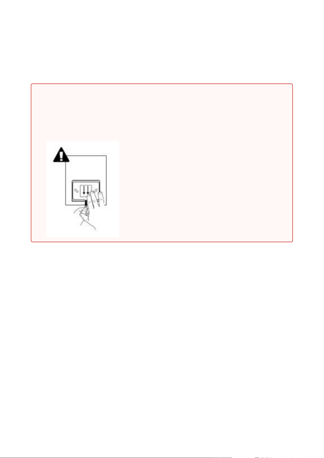
Warning
Having unpacked 2N
®
Clip, remove the metal holder for installation. Use both your
hands at the same time to remove it safely. A careless removal and insufficient push
might lead to a locking latch damage. Hence, follow the mentioned metal holder
instructions below closely!
Push the locking latch in the center of the device
bottom edge with your left hand in such a manner that
it bends sufficiently for the metal holder removal. Do
not push the locking latch from the top. You might get
injured while removing the metal holder.
Grasp the metal holder with your right hand and slide it
downwards for removal.
2N® Clip User Manual
12 / 75
3.2.1 Flush Mounting Box Installation of Device
2N
®
Clip can be installed into a KU 68 flush mounting box using a metal holder for EU (included
in the package), the recommended height of a standard installation being 135 cm from the
ground level. The installation heights may vary depending on the device use. The device can
also be installed directly on a wall without a mounting box.
1.
2.
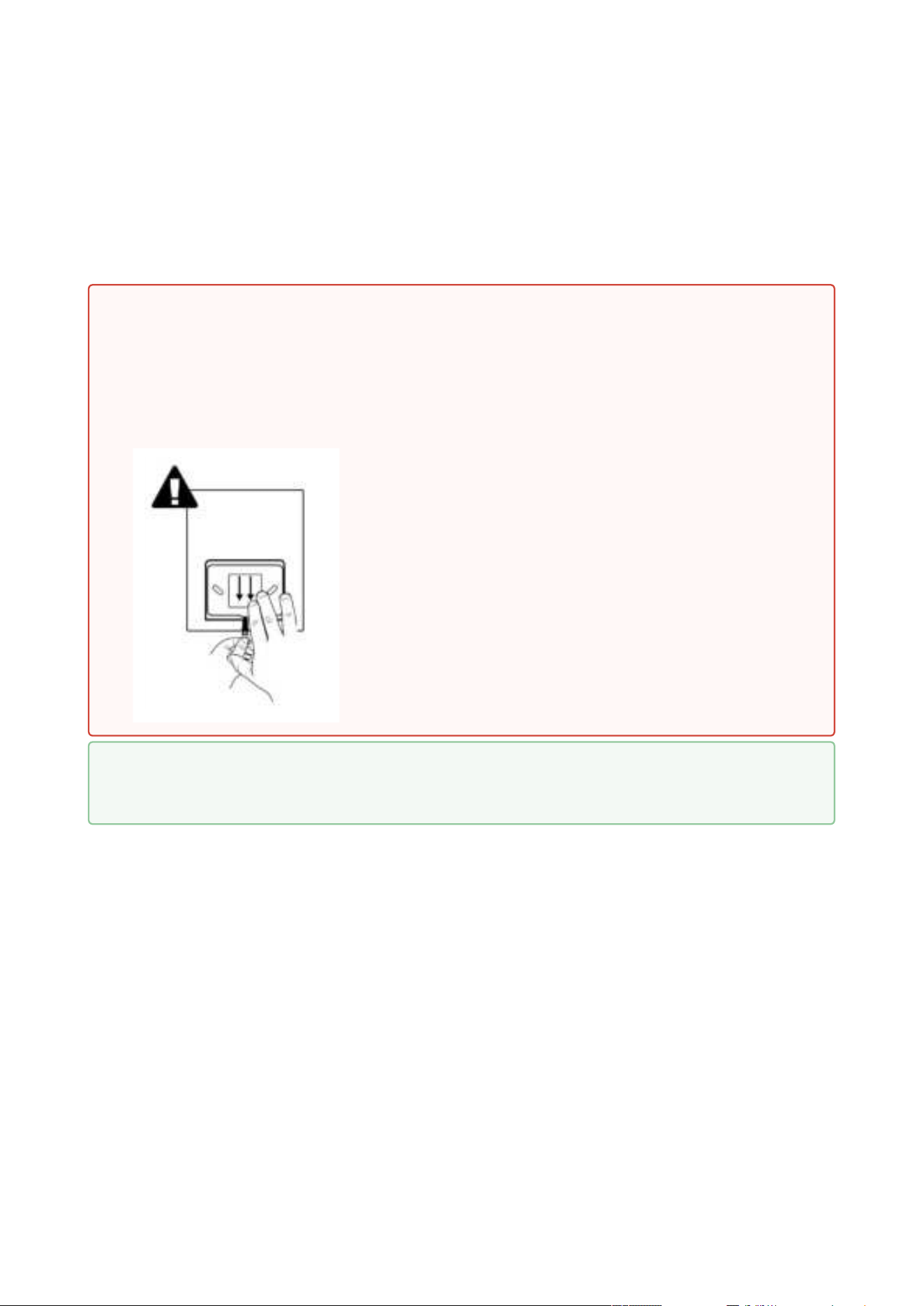
Warning
Having unpacked 2N
®
Clip, remove the metal holder for installation. Use both your
hands at the same time to remove it safely. A careless removal and insufficient push
might lead to a locking latch damage. Hence, follow the mentioned metal holder
instructions below closely!
Push the locking latch in the center of the device
bottom edge with your left hand in such a manner that
it bends sufficiently for the metal holder removal. Do
not push the locking latch from the top. You might get
injured while removing the metal holder.
Grasp the metal holder with your right hand and slide it
downwards for removal.
Tip
Drilling Template
2N® Clip User Manual
13 / 75
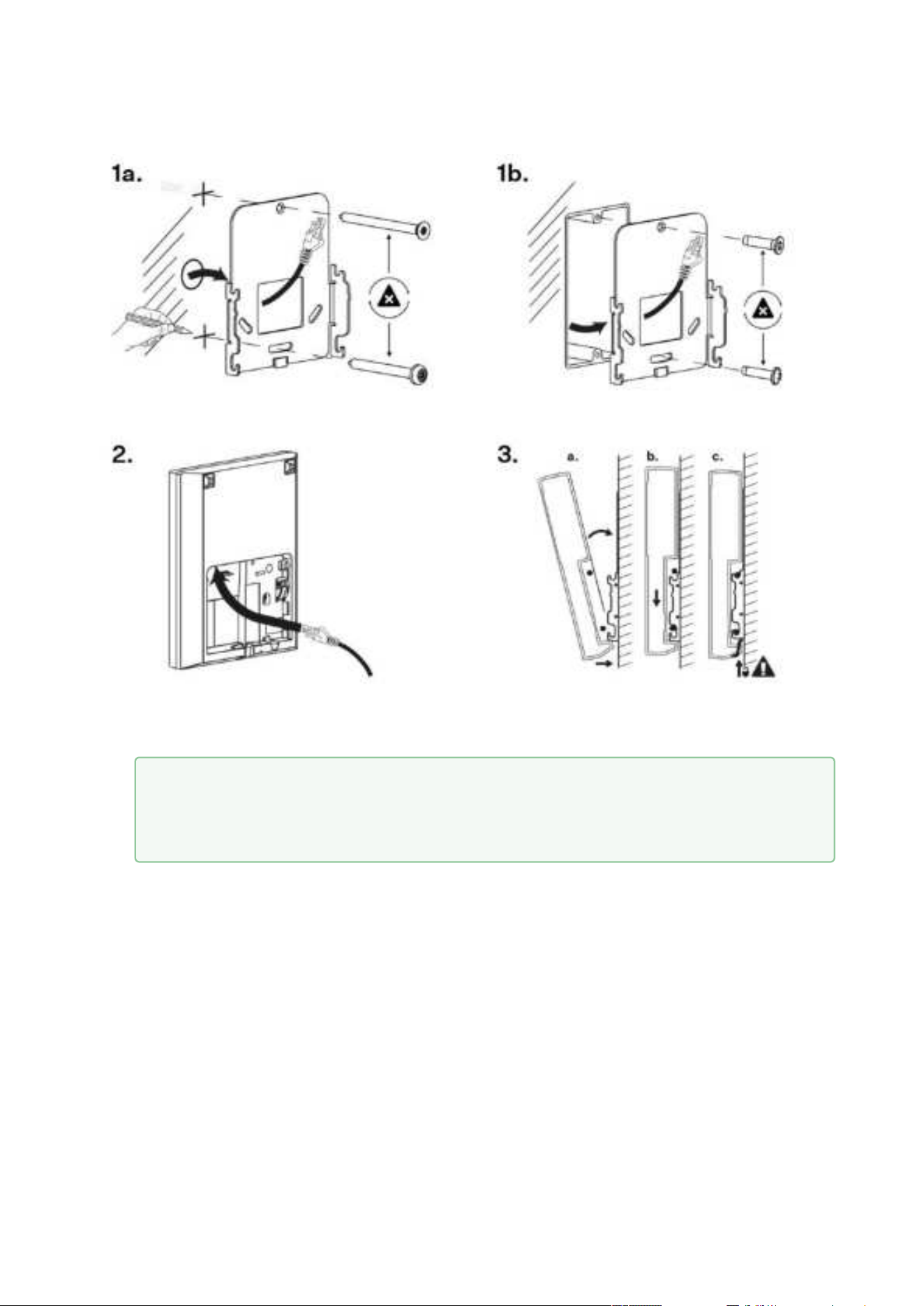
1.
2.
3.
a.
b.
c.
4.
Draw the pre-prepared LAN connector leading from the wall through the metal holder.
Make sure that it is properly oriented for device connection after mounting.
Level the holder as required using a water level and drill it into the mounting box. The wall
mounting screws are not part of the delivery, the included screws are only for the
mounting box installation.
Connect the LAN connector to the device.
Put the device under the holder with its bottom edge first. Then put the device
vertically on the wall keeping the device bottom edge under the holder.
Slide the device gently downwards along the wall.
Lock the latch to fit the device completely.
Now the device is ready for basic operation.It is necessary to perform software
configuration to achieve full functionality of the device.
Tip
Make sure to ensure the proper orientation while installing the holder on the wall.
To do this, mark the bulge profile on the holder bottom side.
2N® Clip User Manual
14 / 75
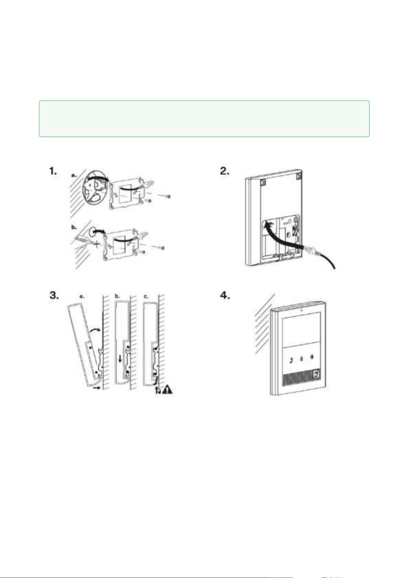
1.
2.
3.
a.
You are advised to use a metal holder (not included in the package) for 2N
®
Clip installation in
the USA. With the aid of this holder, the device can be installed into a universal US single-gang
mounting box. The device can also be installed directly onto a wall without a mounting box.
Draw the pre-prepared LAN connector leading from the wall through the metal holder.
Make sure that it is properly oriented for device connection after mounting. If necessary,
align the holder using a level and drill it into the mounting box or on the wall. The wall
mounting screws are not part of the delivery, the included screws are only for the
mounting box installation.
Connect the LAN connector to the device.
Put the device under the holder with its bottom edge first. Then put the device
vertically on the wall keeping the device bottom edge under the holder.
Tip
Drilling Template

2N® Clip User Manual
15 / 75
b.
c.
Slide the device gently downwards along the wall.
Lock the latch to fit the device completely.
Now the device is attached properly. There is a slight distance between the device and the wall
due to a rather big size of the metal holder, which is fully compliant with the installation
instructions.
Now the device is ready for basic operation.It is necessary to perform software configurationto
achieve full functionality of the device.
2N® Clip User Manual
16 / 75
3.3 Stand Installation
Alternatively, the device can be installed into a stand placed on a desk, for example. The stand is
not included in the package.
Within installation preparations, take out the pre-prepared cabling, UTP cable, doorbell (twin)
cable and power supply. Shorten the cables to the required length. Crimp the RJ-45 connector
onto the UTP cable. Connect the doorbell twin cable together with the LAN connector to the
connector.
1.
2.
Warning
Having unpacked 2N
®
Clip, remove the metal holder for installation. Use both your
hands at the same time to remove it safely. A careless removal and insufficient push
might lead to a locking latch damage. Hence, follow the mentioned metal holder
instructions below closely!
Push the locking latch in the center of the device
bottom edge with your left hand in such a manner that
it bends sufficiently for the metal holder removal. Do
not push the locking latch from the top. You might get
injured while removing the metal holder.
Grasp the metal holder with your right hand and slide it
downwards for removal.
2N® Clip User Manual
17 / 75
1.
2.
Draw the pre-prepared LAN connector through the stand bottom and connect it into the
LAN connector socket. Place the cable into the pre-prepared groove in the center of the
stand bottom. Unstick the protective foil from the stand antislip surfaces.
Put the stand including the properly drawn and connected cable on the device. First snap
in the stand hooks, then tilt the stand towards the device and lock the latch on the stand
top edge into the device body.
Now the device is ready for basic operation. It is necessary to perform software configuration to
achieve full functionality of the device.
To remove the device from the stand, reverse the steps - start by releasing the locking latch on
the top edge of the stand.
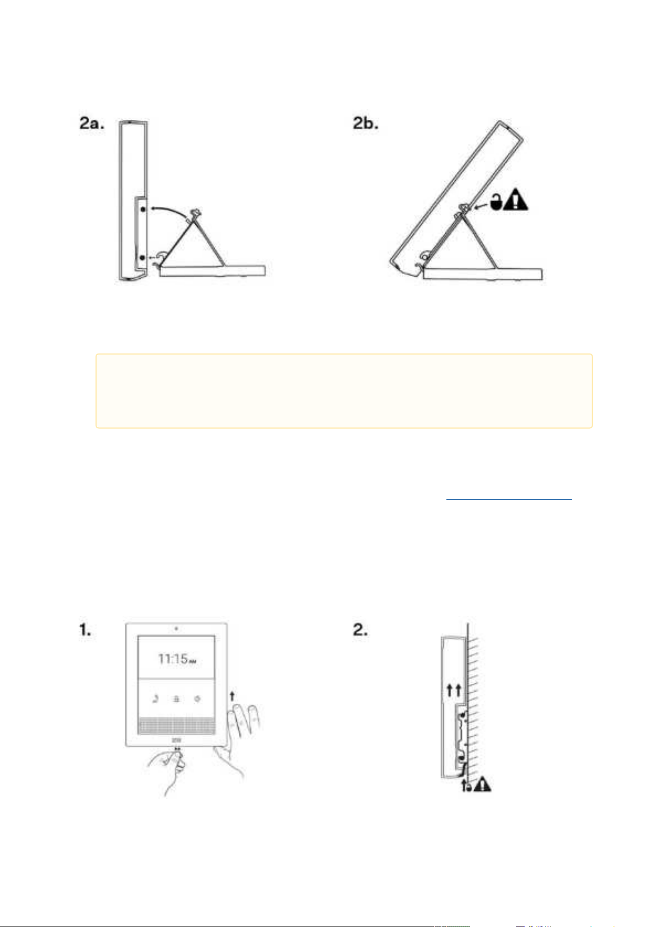
3.4 Device Removal
Caution
We recommend that you use a CAT5e UTP cable to fit the stand bottom groove
size.
2N® Clip User Manual
18 / 75
1.
2.
Press the locking latch located in the center of the device back bottom edge. Pull the
device gently upwards to release it from the metal holder/stand.
Remove the device from the hooks and take it away safely.
3.5 Power Supply
2N
®
Clip is fed via an Ethernet cable connected to a PoE power supply or PoE supporting
Ethernet switch/router.
Power supply must comply with PS1 class output
Supply type
PoE, IEEE 802.3af
3.5.1 PoE Supply Connection
Use a standard straight RJ-45 terminated cable to connect 2N
®
Clip to the Ethernet. The device
supports the 10BaseT and 100BaseT protocols.
Ethernet cable connector Ethernet socket
•
•
Warning
Do not connect any external power supply if PoE is used and vice versa.
Connection of a defective or improper power supply may lead to a temporary or
permanent device failure.
•
•
Caution
Factory reset results in a change of the Ethernet interface configuration.
A defective Ethernet cable may lead to a high packet loss in the Ethernet and
subsequent instability and poor call quality.

2N® Clip User Manual
19 / 75
Warning
This device cannot be connected directly to telecom lines (or public wireless networks)
of any telecom service providers (i.e. mobile providers, landline providers or Internet
providers). A router has to be used for the device Internet connection.

2N® Clip User Manual
20 / 75
•
•
•
•
•
•
•
•
•
•
•
4. Quick Guide
This section describes access to the 2N
®
Clip configuration web interface, firmware upgrade
procedure and factory default reset
.
4.1 Device Configuration Interface Access
4.2 IP Address Retrieval
4.3 Firmware Update
4.4 Device Restart
4.4 Factory Default Reset
4.1 Device Configuration Interface Access
2N
®
Clip is configured via the administration web interface. Connect the device to the LAN IP
and make sure it is properly powered. You have to know the device IP address to gain access.
Retrieve the IP using one of the three methods described in
IP Address Retrieval:
use the freely accessible 2N
®
Network Scanner application,
show the information directly on the device display,
use hardware (RESET button).
4.1.1 Web Interface Login
Fill in the 2N
®
Clip address or domain name into the Internet browser. The login screen is now
displayed.
The default login data are:
Username: Admin
Password: 2n
Should the login screen fail to appear, you must have typed a wrong IP address/port into the
Internet browser or the 2N
®
Clip administration web server has been switched off. If you are not
certain about the IP address, find it as described in
IP Address Retrieval.
4.2 IP Address Retrieval
To retrieve the device IP address, take the following steps:
use the freely accessible 2N
®
Network Scanner application,
show the information directly on the device display,
use hardware (RESET button).
2N® Clip User Manual
21 / 75
1.
2.
3.
•
4.
•
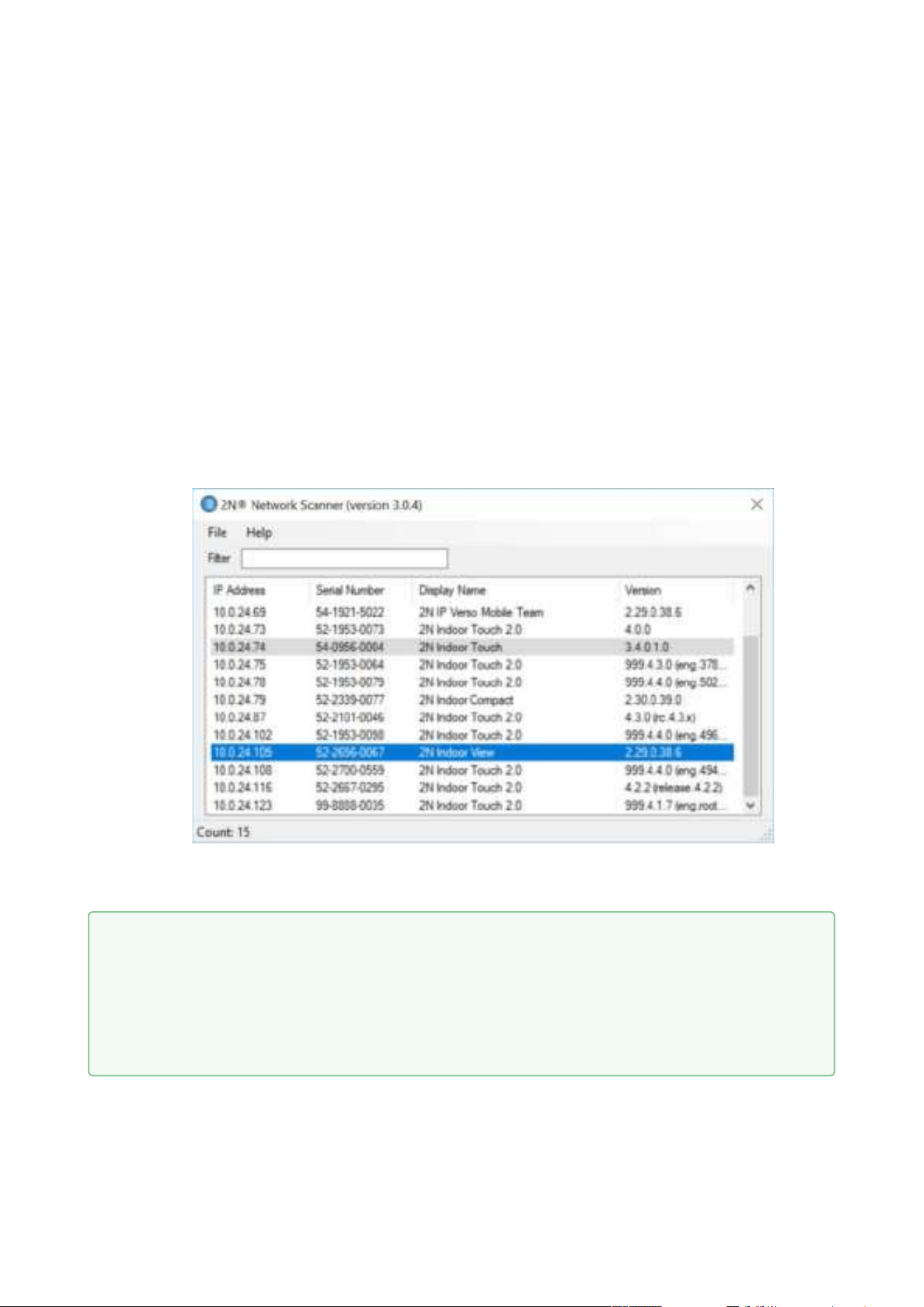
4.2.1 IP Address Retrieval Using 2N®NetworkScanner
The application helps you find the IP addresses of all the 2N devices in the LAN. Download
2N
®
NetworkScanner from the
2N.com website. Make sure that Microsoft .NET Framework 2.0
is installed for successful app installation.
Installation Wizard
Run the 2N
®
NetworkScanner installer.
The Installation Wizard will help you with the installation.
Having installed 2N
®
Network Scanner, start the application using the Microsoft Windows
Start menu.
Once started, the application begins to automatically search the LAN for all the 2N
devices which have been DHCP/statically assigned IP addresses. These devices are
then shown in a table.
Select the device to be configured and right-click it. Select Browse… to open the device
administration web interface login box for configuration.
The default login data are:
Username: Admin
•
•
Tip
Or, double click the selected row in the 2N
®
NetworkScannerlist to access the
device web interface easily.
To change the device IP address, select Config and enter the required static IP
address or activate DHCP.

2N® Clip User Manual
22 / 75
• Password: 2n
2N® Clip User Manual
23 / 75
1.
2.
3.
4.
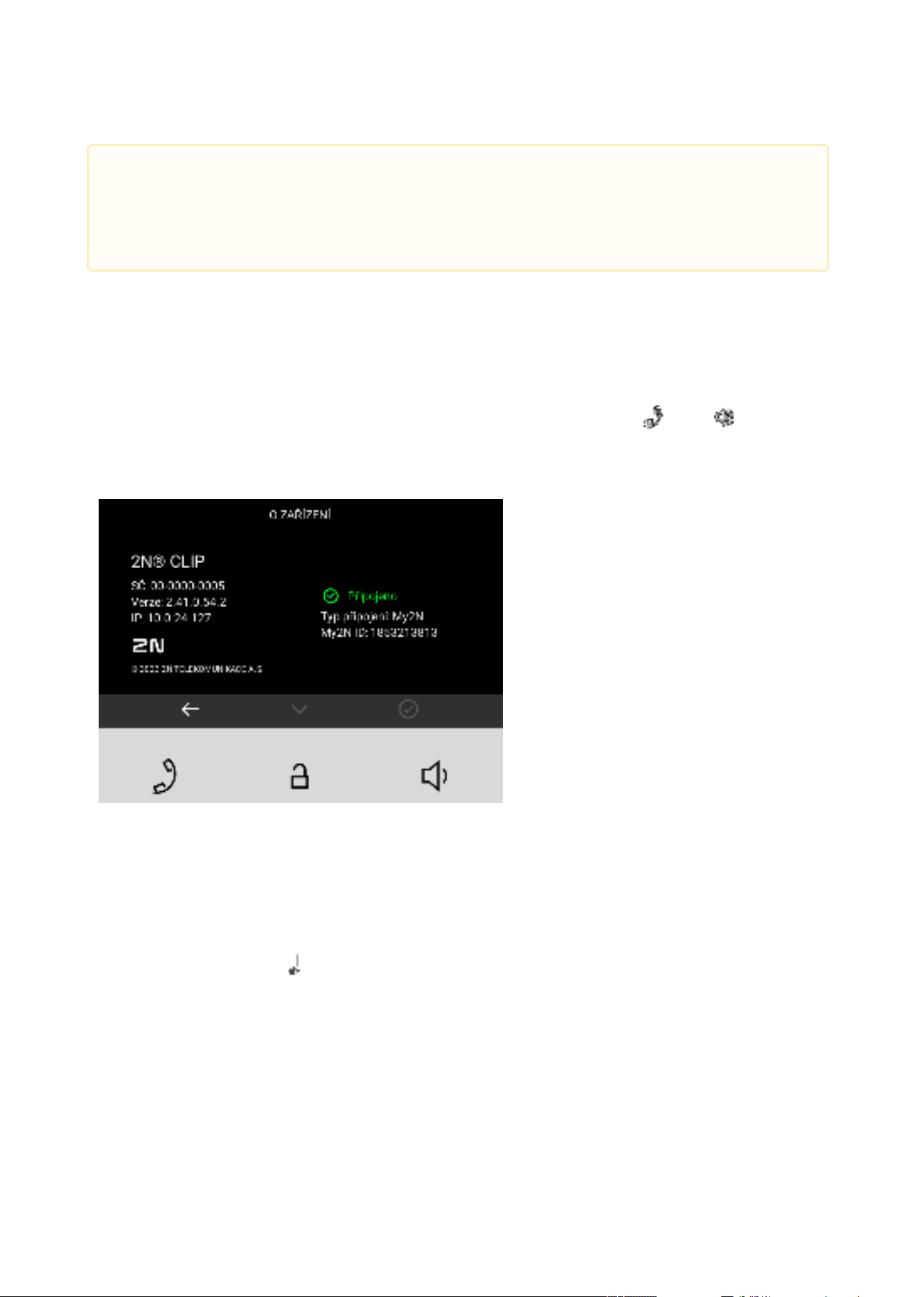
4.2.2 IP Address Retrieval Using Device Display
To retrieve the 2N
®
Clip IP address using 2N
®
NetworkScanner, follow the instructions included
in
IP Address Retrieval Using 2N® Network Scanner.
To retrieve the IP address on the device, press any key to close the device idle mode. The
Settings menu is displayed on the home screen after a long press of the and buttons.
Find the IP address information in the About device menu.
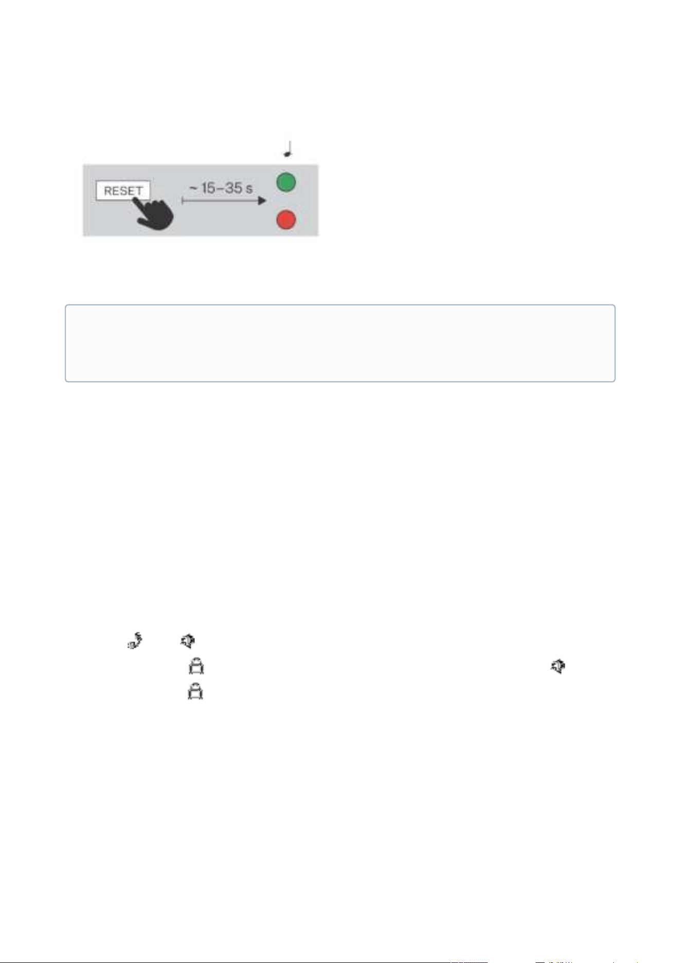
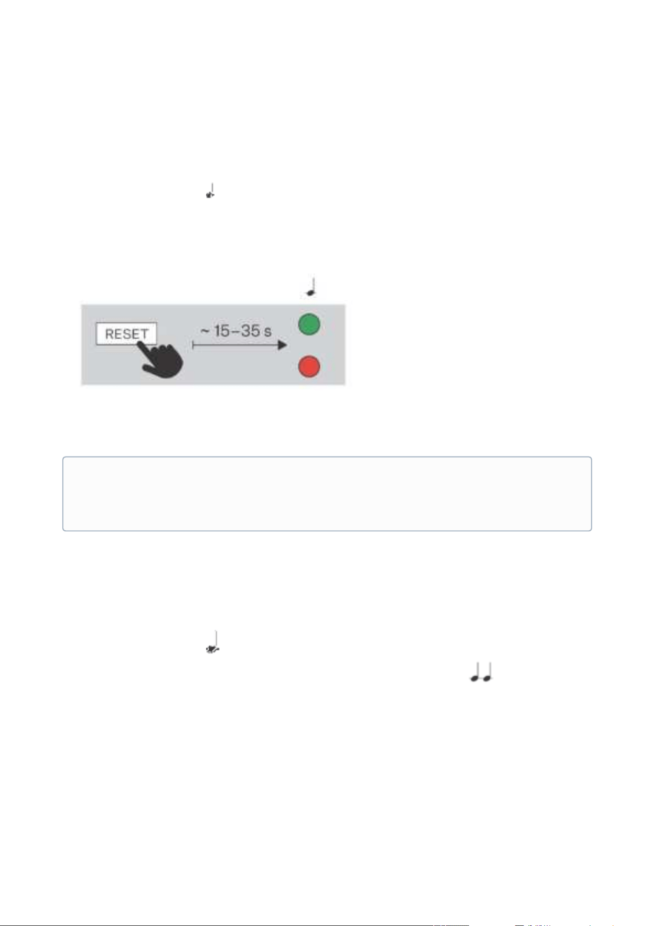
4.2.3 IP Address Retrieval Using Hardware
Follow the instructions below to retrieve the current IP address:
Press and hold the RESET button.
Wait until the red and green LEDs go on simultaneously on the device and the acoustic
signal can be heard (approx. 15–35 s).
Release the RESET button.
The device announces the current IP address via the speaker automatically.
Caution
If the found device is grey highlighted, its IP address cannot be configured using this
application. In that case, click Refresh to find the device again and check whether
multicast is enabled in your network.
2N® Clip User Manual
24 / 75
•
•
•
4.3 Firmware Update
We recommend you to upgrade the 2N
®
Clip firmware during installation. Refer to2N.com for
the latest FW version. Refer to
Maintenance for the firmware upgrade procedure.
4.4 Device Restart
To restart the device, use one of the following options:
the device buttons,
the RESET button,
the web configuration interface.
Restart Using Device Buttons
Press the and buttons on the device simultaneously for a long time to display the
Settings menu. Click to select Device administration > Device restart (and press for
confirmation). Press again to complete the restart. The
Home screen is displayed after
restart. Restarting may take a rather long time after the button press.
Restart Using Reset Button
Find the RESET button on the device backside. The RESET button helps you set factory default
values, restart the device, retrieve the IP address and switch the static/dynamic IP address
setting mode. A short press of the RESET button (< 1 s) restarts the device without making any
Note
The delay between the RESET press and the first light and sound signaling is set to 15–35
s depending on the device model used.
2N® Clip User Manual
25 / 75
1.
2.
3.
4.
5.
6.
configuration changes. The Home screenis displayed after restart. Restarting may take a rather
long time after the button press.
Restart Using Web Configuration Interface
You can also restart the device via the web configuration interface. Refer to here for login
details. Restart the device using the Restart button in the System > Maintenance> System
section. The Home screen is displayed after restart. Restarting may take a rather long time after
the button press.
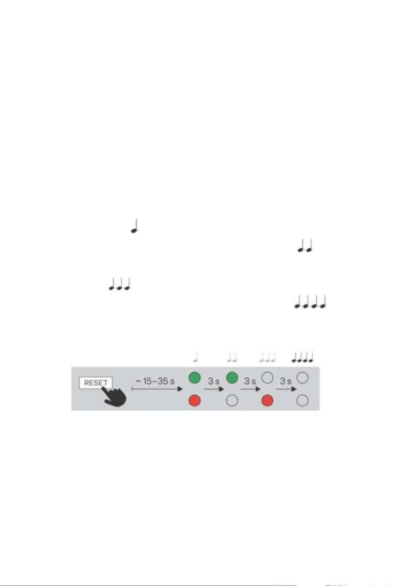
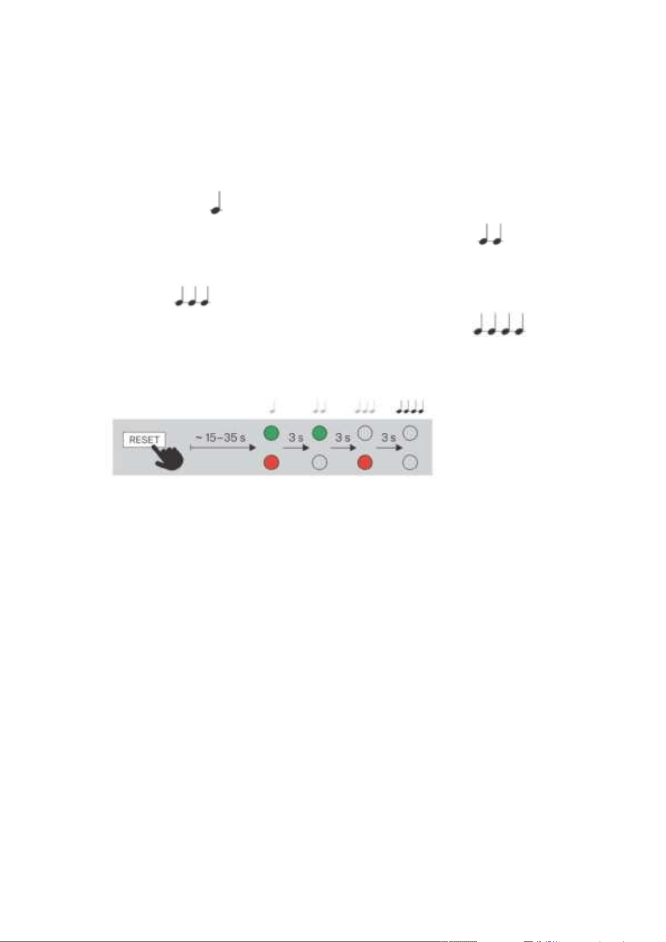
4.4 Factory Default Reset
Follow the instructions below to reset the 2N
®
Clip factory default values:
Press and hold the RESET button.
Wait until the red and green LEDs go on simultaneously on the device and the acoustic
signal can be heard (approx. 15–35 s).
Wait until the red LED goes off and the acoustic signal can be heard (approx. for
another 3 s).
Wait until the green LED goes off and the red LED goes on again and the acoustic signal
can be heard (approx. for another 3 s).
Wait until the red LED goes off and the acoustic signal can be heard (approx. for
another 3 s).
Release the RESET button.
Press the button shortly (< 1 s) to restart the system without changing configuration.
2N® Clip User Manual
26 / 75
•
•
•
•
•
•
•
•
5. Configuration
2N
®
Clip can be configured by software via the configuration web interface or by hardware using
the RESET button. Hardware configuration is used for basic settings only.
Here is what you can find in this section:
5.1 Basic Configuration Using Hardware
5.2 Software Configuration
5.3 Used Ports
5.1 Basic Configuration Using Hardware
Where software configuration is unavailable, make basic settings using the RESET button.
Here is what you can find in this section:
5.1.1 Device Restart
5.1.2 IP Address Retrieval
5.1.3 Static IP Address Setting
5.1.4 Dynamic IP Address Setting
5.1.5 Factory Default Reset
5.1.1 Device Restart
Press the button shortly (< 1 s) to restart the system without changing configuration.
2N® Clip User Manual
27 / 75
1.
2.
3.
4.
1.
2.
3.
4.
5.1.2 IP Address Retrieval
Follow the instructions below to retrieve the current IP address:
Press and hold the RESET button.
Wait until the red and green LEDs go on simultaneously on the device and the acoustic
signal can be heard (approx. 15–35 s).
Release the RESET button.
The device announces the current IP address via the speaker automatically.
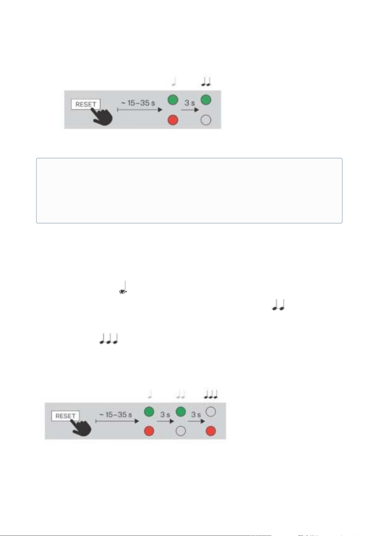
5.1.3 Static IP Address Setting
Follow the instructions below to switch on the Static IP address mode (DHCP OFF):
Press and hold the RESET button.
Wait until the red and green LEDs go on simultaneously on the device and the acoustic
signal can be heard (approx. 15–35 s).
Wait until the red LED goes off and the acoustic signal can be heard (approx. for
another 3 s).
Release the RESET button.
Note
The delay between the RESET press and the first light and sound signaling is set to 15–35
s depending on the device model used.
2N® Clip User Manual
28 / 75
1.
2.
3.
4.
5.
5.1.4 Dynamic IP Address Setting
Follow the instructions below to switch on the Static IP address mode (DCHP ON):
Press and hold the RESET button.
Wait until the red and green LEDs go on simultaneously on the device and the acoustic
signal can be heard (approx. 15–35 s).
Wait until the red LED goes off and the acoustic signal can be heard (approx. for
another 3 s).
Wait until the green LED goes off and the red LED goes on again and the acoustic signal
can be heard (approx. for another 3 s).
Release the RESET button.
•
•
•
Note
The following network parameters will be set after restart:
IP address: 192.168.1.100
Network mask: 255.255.255.0
Default gateway: 192.168.1.1
2N® Clip User Manual
29 / 75
1.
2.
3.
4.
5.
6.
5.1.5 Factory Default Reset
Follow the instructions below to reset the 2N
®
Clip factory default values:
Press and hold the RESET button.
Wait until the red and green LEDs go on simultaneously on the device and the acoustic
signal can be heard (approx. 15–35 s).
Wait until the red LED goes off and the acoustic signal can be heard (approx. for
another 3 s).
Wait until the green LED goes off and the red LED goes on again and the acoustic signal
can be heard (approx. for another 3 s).
Wait until the red LED goes off and the acoustic signal can be heard (approx. for
another 3 s).
Release the RESET button.
2N® Clip User Manual
30 / 75
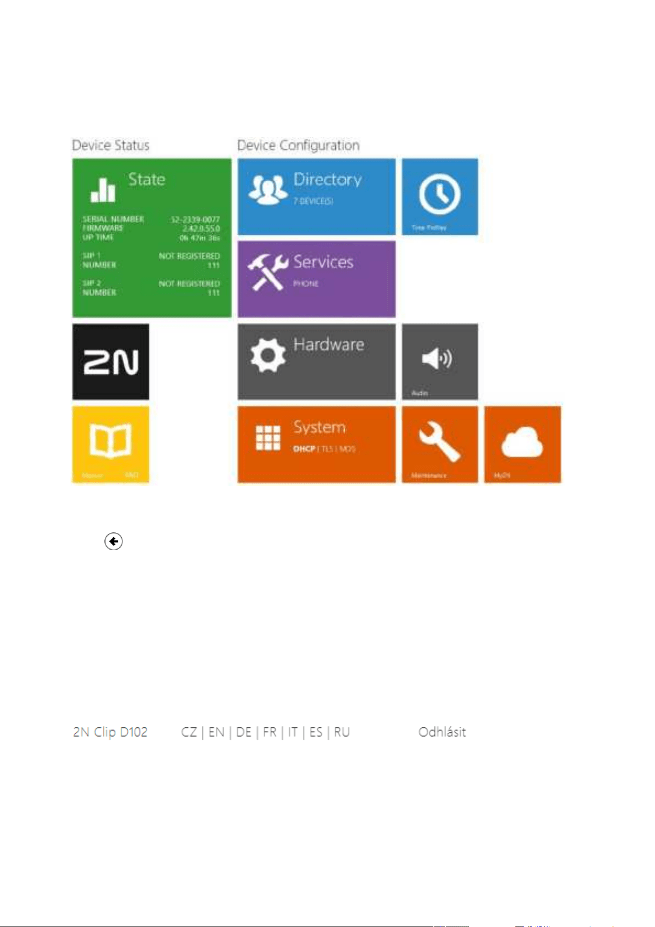
5.2 Software Configuration
The start screen is displayed once you log into the 2N
®
Clip configuration web interface. Use the
button in the left-hand upper corner on each of the following web interface pages to return
to this screen anytime. The screen header includes the device name (refer to the Display Name
parameter in Services > Phone > SIP). Use the menu in the right-hand upper corner of the web
interface for selecting the language. Click Log out in the right-hand upper corner of the screen to
log out from the device, press the question mark icon to display Help or use the bubble to
provide feedback.
5.2.1 Language Selection
Use the menu in the right-hand upper corner of the web interface to select language. Click the
Log out button in the right-hand upper corner to log out.
2N® Clip User Manual
31 / 75
•
•
•
5.2.2 Legend
The start screen is also the first menu level and quick navigation (click on a tile) to selected 2N
®
Clip configuration sections.
5.2.3 Configuration Interface Access
2N
®
Clip is configured via the administration web interface. Connect the device to the LAN IP
and make sure it is properly powered. You have to know the device IP address to gain access.
Retrieve the IP address using one of the three methods described in
IP Address Retrieval:
use the freely accessible 2N
®
Network Scanner application,
show the information directly on the device display,
use hardware (RESET button).
5.2.3.1 Web Interface Login
Fill in the 2N
®
Clip address or domain name into the Internet browser. The login screen is now
displayed.
The default login data are:
Username: Admin
Password: 2n
Should the login screen fail to appear, you must have typed a wrong IP address/port into the
Internet browser or the 2N
®
Clip administration web server has been switched off. If you are not
certain about the IP address, find it as described in
IP Address Retrieval.

2N® Clip User Manual
32 / 75
•
•
•
•
•
•
•
•
5.2.4 State
The Status menu provides clear status and other essential information on the intercom. The
section includes the following menus:
5.2.4.1 Device
5.2.4.2 Services
5.2.4.3 Call Log
5.2.4.4 Events
5.2.4.1 Device
The Device tab displays information on the model, its features, firmware and bootloader
versions, etc.
Device Info
Factory Certificate Installed – specify the user certificate and private key to validate the
intercom right to communicate with the ACS.
Localize Device –acoustic signaling of the device.
5.2.4.2 Services
The Services tab displays the statuses of the network interface and selected services.
5.2.4.3 Call Log
The web configuration Call Log menu provides a list of all accomplished calls. Each call carries
the following information:
contact type,
called/calling user ID,
call date and time,
call duration and status (incoming, outgoing, missed, picked up elsewhere, doorbell
button).
The search box is used for fulltext search in the call name. The check box is used for selecting all
records for bulk deletion. The selected call record can also be deleted individually using the
button.The list includes the last 20 records that are arranged from the latest call to the
oldest one.
5.2.4.4 Events
The Events tab displays the last 500 events captured by the device. Every event includes the
capturing time and date, event type and detailed description. Use the pop-up menu above the
event record to filter the events by the type.
List of events and their meanings:

2N® Clip User Manual
33 / 75
Events Meaning
ApiAccessRequested Generated whenever the request is sent to /api/
accesspoint/grantaccess with the "success" : true
result.
CallSessionStateChanged Event describing the call direction/state, address,
session number and call sequence number.
CallStateChanged Indicates the call direction (incoming, outgoing) and
opponent / SIP account identification at a call state
change (ringing, connected, terminated).
DeviceState Device state indication, startup of the device, for
example.
DtmfEntered DTMF code received in call or off call locally.
DtmfSent DTMF code sent in call or off call locally.
InputChanged Signals a state change of the logic input.
KeyPressed Generated whenever a button is pressed (numeric
keypad digits are 0, 1, 2..., 9 and quick dial buttons are
%1, %2 ...).
KeyReleased Generated whenever a button is released (the digits are
0, 1, 2..., 9 and quick dial buttons are %1, %2 ...).
LoginBlocked Event generated after 3 wrong logins to the web
interface. Contains information about IP address.
RegistrationStateChanged Change of the SIP Proxy registration state.
5.2.5 Directory
Directory is one of the crucial parts of the device configuration. It helps you add new devices (2N
IP intercoms, answering units, etc.).
Up to 200 devices can be added to the directory.

2N® Clip User Manual
34 / 75
•
•
•
•
•
5.2.5.1 Devices
The Search function in the Devices menu works as a fulltext search in names and phone
numbers. It searches for all matches in the whole directory.
Press the button above the table to
add a Device. Or, search a device in the LAN and then add the device as a new contact to the
Directory. T
he icon displays the user settings details. The icon helps remove a device
from the list deleting all its data. You can arrange the list according to the name or phone
number ( feature icon of the device that is allowed to be displayed, feature icon of the
device that is allowed to receive incoming calls, feature icon of the device to which an
alarm call will be set up after the doorbell button is pressed). One list page can display 15, 25 or
50 devices.
Basic Settings
Each device list item includes the following data in the Basic settings block:
Device Name – enter the device name for the selected Phone Book position. This parameter is
optional and helps you find items in the Phone Book more easily.
Displayed Icon – display the reception desk symbol or a standard symbol.
Device Type – set this parameter manually or automatically using search for registered devices
in the Device list.
Phone Number – enter the phone number of the station to which the call shall be routed. Enter
the so-called direct SIP calling. Enter device:device_name for calls to the 2N
®
IP Mobile
application. Set the device name in the mobile application. Enter /1 or /2 behind the phone
number to specify which SIP account shall be used for outgoing calls (account 1 or 2). Enter /S
or /N to force an encrypted or unencrypted call respectively. The account and encryption
selections can be combined into the suffix /1S, for example.
Press the button to set the phone number details.
Phone Number Setting
Call Type – set the scheme in the called destination URI. If you choose Without
scheme, the URI is completed with the data from the SIP account settings. Further
settings include direct SIP calls (sip:), 2N local calls (device:), Crestron calls (rava:) or
calls with video management systems, e.g. AXIS Camera Station (vms:).
Destination – Set the other parts of the called destination URI. As a rule, it contains
the number, IP address, domain, port or device identifier. Enter an asterisk"*" for
calls to the VMS.
Preferred SIP Account – SIP account 1 or 2 is primarily used for calling.
Call Encryption – set mandatory call encryption or no encryption.
Door Opening – via callbacks.
Individual Ringtone – set an individual ringtone for specific contacts to distinguish them better.

2N® Clip User Manual
35 / 75
•
•
•
•
•
•
•
•
•
Alarm Call
Start Call with Doorbell Button Press – a phone call to this device will be set up after the alarm
call button is pressed. Set the doorbell alarm call function in HW >
Digital inputs > Doorbell
button.
Unlock Button Function
Unlock Code – It is used for remote unlocking of the entrance door, for example. Make sure that
the code includes at least two door unlocking characters via the intercom keypad and at least
one door unlocking DTMF character via a phone. The supported characters also include * or #.
Four characters at least are recommended.
5.2.6 Services
The Services section includes the following menus:
5.2.6.1 Phone
5.2.6.2 Unlocking
5.2.6.3 User Sounds
5.2.6.4 Web Server
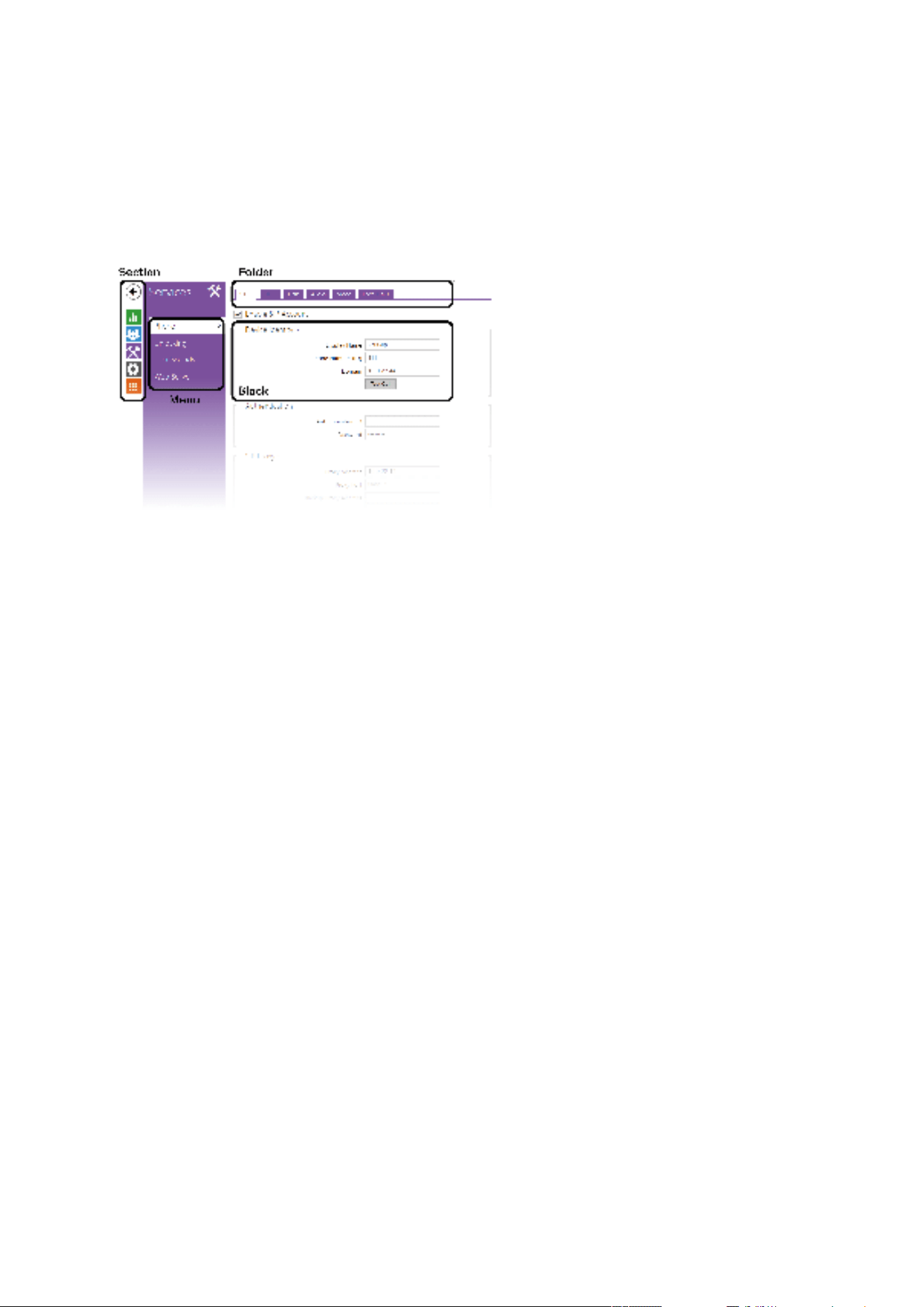
5.2.6.1 Phone
The Phone service is one of the basic functions of the device 2N
®
Clip – helps you establish
connections with other IP network terminal equipment. The device supports the extended SIP.
The Phone menu includes 6 folders:
SIP1andSIP2– complete SIP account settings.
Calls – incoming and outgoing call settings.
Audio – audio codec, DTMF and other audio stream parameter transmission settings.
Video –video codec and SDP codec settings.
2N Indoor Units – general parameters and count of identified LAN devices.
SIP 1 and SIP 2
2N
®
Clip allows two SIP accounts to be configured.
Allow SIP account – allow the SIP account to be used for calling. If disallowed, the account
cannot be used for making outgoing calls and receiving incoming calls.
Device Identity
Display Name – set the name to be displayed as CLIP on the called party’s phone.
Phone Number(ID) – set the device phone number (or another unique ID composed of
characters and digits). Together with the domain, this number uniquely identifies the device
in calls and registration.
Domain – set the domain name of the service with which the device is registered. Typically,
it is identical with the SIP Proxy or Registrar address.

2N® Clip User Manual
36 / 75
Test Call – display a dialog box enabling you to make a test call to a selected phone
number, see below.
Authentication
Use Authentication ID – select the use of an alternative ID for device authentication.
Otherwise, the Phone number value defined above is used.
ID for authentication – select the use of an alternative user ID for device authentication.
Password – set the password for device authentication. If your PBX requires no
authentication, the parameter will not be applied.
SIP Proxy
Proxy Address – set the SIP Proxy IP address or domain name.
Proxy Port – set the SIP Proxy port (typically 5060).
Backup Proxy Address – SIP Proxy IP address or domain name. The address will be used
where the main Proxy fails to respond to requests.
Backup Proxy port – set the backup SIP Proxy port (typically 5060).
SIP Registrar
Allow Registration – allow the device to be registered with the set SIP Registrar.
Registrar Address – set the SIP Registrar IP address or domain name.
Registrar Port – set the SIP Registrar port (typically 5060).
Backup Registrar Address – set the backup SIP Registrar IP address or domain name. The
address is used where the main Registrar fails to respond to requests.
Backup Registrar Port – set the backup SIP Registrar port (typically 5060).
Registration Expiry – set the registration expiry, which affects the network and SIP
Registrar loads by periodically sent registration requirements. The SIP Registrar can modify
the expiry limit without letting you know.
Registration Status – display the current registration status (Unregistered, Registering...,
Registered, Registration completing...).
Cause of Failure – display the cause of the last registration attempt failure – the Registrar’s
last error response, e.g. 404 Not Found.
Advanced Settings
SIP Transport Protocol – set the SIP communication protocol: Choose UDP (default), TCP
or TLS.
Lowest Allowed TLS Version – set the lowest TLS version to be accepted for server
registration and connection setup.
Verify Server Certificate – verify the SIP server public certificate against the CA certificates
uploaded in the device.
Client Certificate – specify the client certificate and private key used for verifying the
intercom’s authority to communicate with the SIP server.
Local Port for SIP – set the local port to be used for SIP signaling. A change of this
parameter will not be applied until the device is restarted. The default value is 5060.

2N® Clip User Manual
37 / 75
PRACKAllowed – enable the PRACK method (reliable confirmation of SIP messages with
codes 101–199).
REFERAllowed – enable the REFER method for call redirection.
SendKeepAlivePackets – define whether or not the device shall periodically inquire
about the called station status via SIP OPTIONS requests during calls (used for detection of
the station failure during calls).
Allow IP Address Filter – enable the blocking of SIP packet receiving from addresses other
than the SIP Proxy and SIP Registrar. The primary purpose of the function is to enhance
communication security and eliminate unauthorized phone calls.
Accept Encrypted Calls Only (SRTP) – set that the SRTP encrypted calls shall only be
received on this account. Unencrypted calls will be rejected. At the same time, TLS is
recommended as the SIP transport protocol for higher security.
Encrypted Outgoing Calls (SRTP) – set that outgoing calls shall be SRTP encrypted on this
account. At the same time, TLS is recommended as the SIP transport protocol for higher
security.
UseMKIinSRTP Packets – enable the use of the MKI (Master Key Identifier), which is
required by the counterparty for primary key identification if multiple keys are rotated in
SRTP packets.
Do Not Play Incoming EarlyMedia – disable playing of the incoming video stream before
the call is picked up (early media), which is sent by some PBXs or other devices. A standard
local ringtone is played instead.
QoSDSCP Value – set the priority of SIP packets in the network. The set value is sent in the
TOS (Type of Service) field in the IP packet header. Enter the value as a decimal number. A
change of this parameter will not be applied until the device is restarted.
External IP Address – set the public IP address or router name to which the device is
connected. If the device IP address is public, leave this parameter empty.
Starting RTP Port – set the initial local RTP port in the range of 64 ports used for audio and
video transmission. The default value is 4900 (i.e. the range is 4900–4963). The parameter is
only set for SIP 1 but applies to both the SIP accounts.
RTPTimeout – set the audio stream RTP packet receiving timeout during a call. If this limit
is exceeded (RTP packets are not delivered), the call will be terminated by the device. Enter
0 to disable this parameter. The parameter is only set for account 1 but applies to both the
SIP accounts.
Broadsoft PBX Compatibility – set the Broadsoft PBX compatibility mode. Having received
re-invite from a PBX in this mode, the intercom replies by repeating the last sent SDP with
currently used codecs instead of sending a complete offer.
SRV Record Rotation – allow SRV record rotation for SIP Proxy and Registrar. This is an
alternative method of transition to backup servers in the event of main server failure or
unavailability.

2N® Clip User Manual
38 / 75
•
•
•
•
•
•
Calls
General Settings
Call Time Limit – set the call time limit after which the call is automatically terminated. The
device beeps 10 s before the call ends to signal that the call end is approaching.If the call
duration is set to 0 and SRTP is not used, the call is not time limited.
Incoming Calls
Call Receiving Mode (SIP 1/2, SIP 2) – set the way of receiving incoming calls. You can set
the call receiving mode for each SIP account separately. The following three options are
available:
Always Busy – the device rejects incoming calls.
Manual Answering – the device rings to signal incoming calls and the user can press
a button to pick up.
Automatic – the device picks up incoming calls automatically.
Local Call Receiving Mode – set the way of receiving incoming local calls.
Always Busy – the device rejects incoming calls.
Manual Answering – the device rings to signal incoming calls and the user can press
a button to pick up.
Automatic – the device picks up incoming calls automatically.
Do Not Disturb Mode with Timeout – ringing is disabled temporarily. If this silent mode is
activated, the device shall not ring when a call comes in.
Outgoing Calls
Connecting Time Limit – set the maximum outgoing call connection timeout after which
the calls are automatically terminated. If the calls are routed to the GSM network via GSM
gateways, you are advised to set a value longer than 20 s.
Ring Time Limit – set the maximum call setup and ringing time in which all outgoing calls
are automatically terminated. If the calls are routed to the GSM network via GSM gateways,
you are advised to set a value longer than 20 s. Minimum value: 1 s, maximum value: 600 s.
Set 0 to disable the time parameter.
Audio
Audio Codecs
Enable/disable the use of audio codecs for call setups and set their priorities in this block.
DTMF Sending
This block helps you define how DTMF characters shall be sent from the device. Check the
opponent’s DTMF receiving options and settings to make the function work properly.

2N® Clip User Manual
39 / 75
In-Band(Audio) – enable classic DTMF dual tone sending in the audio band.
RTP(RFC-2833) – enable DTMF sending via the RTP according to RFC-2833.
SIPINFO(RFC-2976) – enable DTMF sending via SIP INFO messages according to RFC-2976.
DTMF Receiving
This block helps you define how DTMF characters shall be received from the intercom.
Check the opponent’s DTMF receiving options and settings to make the function work
properly.
In-Band(Audio) – enable classic DTMF dual tone receiving in the audio band.
RTP(RFC-2833) – enable DTMF receiving via the RTP according to RFC-2833.
SIPINFO(RFC-2976) – enable DTMF receiving via SIP INFO messages according to
RFC-2976.
Transmission Quality Settings
QoS DSCP Value – set the audio RTP packet priority in the network. The set value is sent in
the TOS (Type of Service) field in the IP packet header.
Jitter Compensation – set the buffer length for compensation of interval unevenness in
audio packet arrivals. Set a higher value to increase the receiving immunity at the cost of a
higher sound delay.
Video
Video Codecs
Enable/disable the use of video codecs for call setups and set their priorities.
Extended Codec Settings
Enabled – enable the packetization mode and set the payload type for each codec. The
payload type will be selected automatically in case it cannot be set manually.
SDPPayloadType– set the "payload type" for video codec H.264 (packetization mode 1).
Set a value from the range of 96 through 127, or 0 to disable this codec type.
Local Calls
Enable Local Calls – enable calls between 2N devices in the LAN. With this function off, the other
LAN devices cannot locate this device, i.e. cannot call the device in the device:device_ID format.
Network Identification
Device ID – set the device ID to be displayed in the LAN device list in all the 2N devices in
one and the same LAN. You can direct a call to this device by setting the user phone number
as device:device_ID in these devices.

2N® Clip User Manual
40 / 75
•
•
•
•
•
Connection to Intercoms
Access Key 1, 2 – set the access key shared by the 2N answering units and intercoms. If the
keys in the 2N answering units and the intercoms fail to match, the devices cannot
communicate, i.e. the intercom cannot call the 2N answering unit and vice versa.
Connection to Answering Units
Access Key – set the access key shared by the 2N answering units and intercoms. If the
defined key in the answering units and the intercoms fails to match, the devices cannot
communicate, i.e. the intercom cannot call the answering unit and vice versa.
Multicast address – set the multicast address to which messages shall be sent between the
answering units.
LAN Devices
LAN Device Count – display the count of devices in the LAN.
Show list of LAN devices – show a detailed list of LAN devices.
5.2.6.2 Unlocking
Unlocking is another function of 2N
®
Clip, which sets the remote door unlocking parameters.
Unlocking Settings
Default unlocking code – this code is used if a call is set up with a device/phone number that is
not in the unit’s directory.
Hang up after door unlocking – the call is ended after the successful door unlocking request is
sent.
Hang-up timeout – the call is ended when the set timeout elapses after the successful door
unlocking request is sent.
5.2.6.3 User Sounds
2N
®
Clip signals variable operational statuses with a sequence of tones. If the standard signaling
tones do not meet your requirements, you can modify them.
Sound Mapping
Sound Mapping
Busy Tone – set the busy tone to be played when the called user is busy.
Call End Signaling – set the sound to be played upon the call end.
Ringtone – set the sound to be played when the called user is ringing.
Ringing before Call Answering – set the sound to be played before answering an
incoming call (intercom ringtone).
Doorbell – set the sound to be played when the door button is pressed.

2N® Clip User Manual
41 / 75
•
•
•
5.2.6.4 Web Server
2N
®
Clip can be configured using a common browser that approaches the web server integrated
in the device. The HTTPS protocol is used for the browser - device communication.
Basic Settings
Device Name – set the device name to be displayed in the right-hand upper corner of the web
interface, in the login window and in other applications if necessary (2N
®
Network Scanner,
etc.).
WebInterface Language – set the default language for the administration web server login. Use
the upper toolbar buttons to change the web interface language temporarily any time.
Password – set the device access password. Click the pencil icon to change the
password.Make sure that the password contains 8 characters at least, including one small
alphabet letter, one capital alphabet letter and one digit.
Advanced Settings
HTTPport – set the web server port for HTTP communication. The port change will not be
applied until the device is restarted.
HTTPS port – set the web server communication port via the secured HTTPS. The port change
will not be applied until the device is restarted.
Lowest Allowed TLS Version – define the lowest TLS version allowed for connection to the
device.
HTTPSServer Certificate – set the server certificate and private key used for encrypting the
communication between the device HTTPS server and user web browser.
Allow Remote Access – enable remote access to the device web server from off-LAN IP
addresses.
User Localization
Original Language – download an original XML file from the device, which contains all the web
user interface texts in English.
User Language – upload, download and remove, if necessary, the user file including custom
translations of the web user interface texts.
5.2.7 Hardware
The Hardware section provides the device hardware settings and includes the following menus:
5.2.7.1 Audio
5.2.7.2 Display
5.2.7.3 Digital Inputs

2N® Clip User Manual
42 / 75
5.2.7.1 Audio
2N
®
Clip is equipped with a speaker. Set the phone call and state signaling volume control in
this configuration section.
Master Volume (
button-controlled) controls the master volume of the device and affects the
volume of both the calls and signaling tones. Consider the noise level of the ambient
environment while setting this parameter.
Phone Call Volume
Call Volume – set the phone call volume.
Ringing Volume – set the incoming call signal loudness.
Call Progress Tone Volume – set the dial, ring and busy tone volume values. In case the call
progress tones are automatically generated by the PBX, this setting will not be applied.
Signaling Volume
Key Beep Volume– set the key beep volume. The volume values are relative against the set
master volume.
Warning Tone Volume – set the warning and signaling tone volume values. The volume values
are relative against the set master volume.
Do Not Play Warning Tones – disable playing of the following operational state signaling:
Internal application started, IP address received and IP address lost.
5.2.7.2 Display
The Display menu helps you set the display appearance and functionality parameters as well as
the parameters of menu shown on the display.
Basic Settings
Set the basic display parameters in this block.
Language – set the language for the texts to be displayed. Choose one of the eight pre-defined
languages (CZ, EN, DE, NL, FR, ES, IT).
Time Format – set the time format to be displayed.
Activate Screen Lock – activate the device lock in the Idle mode. Remember to enter the screen
lock PIN after unlocking the user interface.
Show Settings Menu – enable this parameter to make the device show the Settings menu on
the display. Or, configure the device via the web and remote access.
When the Doorbell Button Function is set to Doorbell (refer to Digital Inputs), a bell activation
notification is displayed whenever the doorbell is pressed. If the Idle time transition timeout is
≤120 s, the notification will be displayed for 120 seconds. If the Idle time transition timeout is
>120 s, the home screen will be displayed after the 120-second timeout until the device goes into
the Idle mode.

2N® Clip User Manual
43 / 75
1.
2.
3.
4.
5.
•
•
•
•
•
•
•
Backlight
Display Backlight Intensity – set the backlight brightness level. The value is given as a
percentage of the maximum possible LED brightness.
Go to Idle Mode In – set the timeout after which the devices goes into the Idle mode due to
inactivity.
User Localization
Original language – download a localization file template for a translation of your own. It is
an XML file including all the texts in English shown on the display.
User Language – upload , remove and download a localization file of your own.
Custom Language Upload
Download the original language file (English).
Modify the file using a text editor (replace the English texts with your own ones).
Upload the modified localization file back to the intercom.
SetLanguage to Custom in
Basic Settings.
Check and correct if necessary the texts on the intercom display.
5.2.7.3 Digital Inputs
The Digital Inputs menu describes the digital input options for the device.
Doorbell Button
Doorbell Button Function – select a doorbell function (doorbell, alarm call). The button is used
either as a classical doorbell or for alarm call activation.
5.2.8 System
The System section includes the following menus:
5.2.8.1 Network
5.2.8.2 Date and Time
5.2.8.3 Functions
5.2.8.4 Certificates
5.2.8.5 Auto Provisioning
5.2.8.6 Diagnostics
5.2.8.7 Maintenance

2N® Clip User Manual
44 / 75
5.2.8.1 Network
2N
®
Clip is connected to the LAN and has to be assigned a valid IP address or obtain the IP
address from the LAN DCHP server. The Network section helps you configure the IP address and
DHCP.
If the network uses the RADIUS server and 802.1x-based verification of connected equipment,
you can make the intercom use the EAP-MD5 or EAP-TLS authentication. Set this function in the
802.1x tab.
Basic
Use DHCP Server – enable automatic obtaining of the IP address from the LAN DHCP server. If
no DHCP server is existing or available in the network, set the network manually.
Static IP Address Setting
Static IP Address – static IP address of the device. The address is used together with the below
mentioned parameters if the Use DHCP Server parameter is disabled.
Network Mask – set the network mask.
Default Gateway – set the address of the default gateway, which provides communication with
off-LAN devices.
DNS Setting
Always Use Manual Setting – enable manual setting of the DNS server addresses.
PrimaryDNS – primary DNS server address for translation of domain names to IP addresses.
SecondaryDNS – secondary DNS server address, which is used in case the primary DNS is
inaccessible.
Network Identification
Hostname – set the device identifier in the network.
Vendor Class Identifier – set the manufacturer identifier as a character string for DHCP Option
60.
VLAN Settings
VLAN Enabled – enable the virtual network support (VLAN according to 802.1q). Also set the
virtual network ID to make the function work.
VLANID – select a virtual network ID in the range of 1–4094. The device shall only receive
Tip
To retrieve the IP address, use 2N
®
NetworkScanner, which can be downloaded freely
from
2N.com. Refer to IP Address Retrieval Using 2N®NetworkScanner for details.

2N® Clip User Manual
45 / 75
packets with the set ID. An incorrect setting may result in a connection loss and subsequent
factory reset.
LAN Port Settings
Required Port Mode – set the LAN port mode to be preferred (Automatic or Half Duplex – 10
Mbps). The bit rate is reduced to 10 Mbps in case the available LAN cabling is unreliable for a 100
Mbps traffic.
Available Modes– select the modes to be offered for auto-negotiation.
Current Port Status – current network interface port status (Half or Full Duplex – 10 Mbps or
100 Mbps).
802.1x
Device Identity
Device identity – username (identity) for authentication via EAP-MD5 and EAP-TLS.
MD5 Authentication
Authentication enabled – enable network device authentication via the 802.1x EAP-MD5
protocol. If the network does not support 802.1x, the intercom will become unavailable.
Password – enter the access password for EAP-MD5 authentication.
TLS Authentication
Authentication enabled – enable network device authentication via the 802.1x EAP-MD5
protocol. If the network does not support 802.1x, the intercom will become unavailable.
Trusted certificate – specify the set of trusted certificates for verification of the RADIUS server
public certificate validity. Choose one of three certificate sets, see the Certificates. If the CA
certificate is not included, the RADIUS server public certificate is not verified.
Client Certificate – specify the user certificate and private key for verification of the intercom
authorization to communicate via the 802.1x-secured network element port in the LAN. There
are three sets of user certificates and private keys, refer to the Certificates subsection, see
Certificates.
PEAP MSCHAPv2 authentication
Authentication Allowed – enable authentication of network devices via the 802.1x PEAP
MSCHAPv2 protocol. If the network does not support 802.1x, the intercom will become
unavailable.
Trusted certificate – specify the set of trusted certificates for verification of the RADIUS server
public certificate validity. Choose one of three certificate sets, see the Certificates. Certificates
•
Caution
The authentication setting changes will not apply until the device is restarted.

2N® Clip User Manual
46 / 75
subsection. If no trusted certificate is included, the RADIUS public certificate is not verified.
Password – enter the access password for PEAP-MSCHAPv2 authentication.
5.2.8.2 Date and Time
2N
®
Clip is equipped with a real time clock without power outage backup. Select Use Time from
Internet to synchronize the device time with the Internet time or click Synchronize with Browser
to synchronize time with your current PC time.
Current Time
Use Time from Internet – enable the NTP server use for device time synchronization.
Synchronize with Browser – press the button to synchronize the device time with your current
PC time.
Time zone
Automatic Detection – define whether the time zone shall be detected automatically from
My2N. In case automatic detection is disabled, the Manual Selection parameter is used
(manually selected time zone or Own rule).
Detected Time Zone – display the automatically retrieved time zone. In case the function is
unavailable or disabled, N/A is displayed.
Manual Selection – set the installation site time zone. The setting defines time shifts and
summer/winter time transitions.
Custom Rule – if the device is installed on a site that it not included in the Time Zone parameter,
set the time zone rule manually.
NTP Server
NTP Server Address – set the IP address/domain name of the NTP server used for the device
internal time synchronization. The server IP address and domain name cannot be set if Use Time
from Internet is disabled.
NTP Time Status – display the status of the last attempt to synchronize the local time using the
NTP server (Not synchronized, Synchronized, Error).
Note
The device does not need the current date and time values for its basic function.
Caution
It is recommended that the Use time from Internet function is enabled for a maximum
accuracy and reliability. The device time error can be up to ±2 minutes per month under
normal operation conditions.

2N® Clip User Manual
47 / 75
•
•
•
1.
2.
3.
5.2.8.3 Functions
The menu provides a list of published beta functions designed for user testing.
The list includes:
function name
function status {started/stopped)
event that starts/stops the function
The function will not be started/stopped until the device is restarted. The status change request
can be cancelled using the Interrupt event before the device is restarted.
Beta Function Name Description
Password-Protected Configuration
File
This function helps you encrypt the configuration file
with a password during backup (refer to
5.2.8.7
Maintenance). To upload the configuration file to the
device, you need to enter a security password. If the
password fails to match, the configuration file will
not be uploaded.
5.2.8.4 Certificates
Some 2N
®
Clip LAN services use the secure TLS protocol for communication with the other LAN
devices. This protocol prevents third parties from eavesdropping on or modifying call contents.
TLS is based on one/two-sided authentication, which requires certificates and private keys.
Services Using TLS Protocol
Web server (HTTPS)
802.1x (EAP-TLS)
SIPs
The device allows you to upload up to 3 sets of CA certificates, which help you authenticate the
communicating device, and also 3 user certificates and private keys for encryption purposes.
Each certificate-requiring service can be assigned one of the certificate sets, refer to
5.2.6.4 Web
Server.
Note
The test functions are not warranted and 2N TELEKOMUNIKACE a.s. shall not be held
liable for any functionality limitations and damage incurred as a result of functionality
limitations of the beta functions.The beta functions are provided for testing purposes
exclusively.

2N® Clip User Manual
48 / 75
1.
2.
3.
4.
The device supports the DER (ASN1) and PEM certificate formats.
Upon the first power up, the intercom automatically generates the Self Signed certificate and
private key for the Web server services without forcing you to load a certificate and private key
of your own.
The current list of uploaded CA and user certificates is available in the following two folders: CA
Certificates and User Certificates.
Certificate Upload
Click to upload a certificate saved in the storage.
Select the certificate (or private key) file in a dialog window.
Press the Upload button.
Press to remove a certificate from the device.
5.2.8.5 Auto Provisioning
My2N
The My2N cloud platform is used for remote administration and configuration of the 2N IP
devices and helps you remotely connect to the device web interface.
My2N Enabled – enable connection to My2N.
Note
If you use the Self Signed certificate for encryption of the device web server – browser
communication, the communication is secure, but the browser will warn you that it is
unable to verify the device certificate validity.
•
•
Note
A certificate with a private RSA key longer than 2048 bits can be rejected. and the
following message will be displayed: “The private key file/password was not
accepted by the device!”
For certificates based on elliptic curves use the secp256r1 (aka prime256v1 aka
NIST P-256) and secp384r1 (aka NIST P-384) curves only.

2N® Clip User Manual
49 / 75
My2N Security Code
Serial Number – display the device serial number for which the My2N code is valid.
My2NSecurityCode – the code for adding the device to My2N.
Generate New – the active My2N Security Code will be invalidated and a new one will be
generated.
Connection State
The information on the connection of the device to My2N is provided.
My2NID – unique identifier of the company created via the My2N portal.
TR069
Use this tab to enable and configure remote device management via the TR-069 protocol.
TR-069 helps you reliably configure the device parameters, update and back up configuration
and/or upgrade device firmware.
The TR-069 protocol is utilized by the My2N cloud service. Make sure that TR-069 is enabled and
Active profile set to My2N to make the device work with My2N properly. Only then the device will
be able to log in to My2N periodically for configuration.
This function helps you connect the device to your ACS (Auto Configuration Server). In this case,
the connection to My2N will be disabled in the device.
My2N / TR069 Enabled – enable the connection to My2N or another ACS.
General Settings
Active Profile – select one of the pre-defined profiles (ACS), or choose a setting of your own
and configure the ACS connection manually.
Next Synchronization in – display when the device shall contact the remote ACS.
Connection Status – display the current connection to the ACS or the error state
description.
Communication Status Detail – server communication error code or HTTP status code.
Connection Test – test the connection to TR069 according to the set profile, refer to Active
Profile. The test result is displayed in the Connection status.
5.2.8.6 Diagnostics
The device 2N
®
Clip allow you to send system messages to the Syslog server including relevant
information on the device states and processes for recording, analysis and audit. It is
unnecessary to configure this service for common operations.
Diagnostics
Tools
Verify Network Address Accessibility – verify the network address accessibility via the
Ping command in standard operating systems. Press Ping to display a dialogue for you to

2N® Clip User Manual
50 / 75
1.
2.
3.
1.
2.
3.
4.
5.
enter the IP address/domain name and press Ping to send the test data to the set address. If
the IP address/domain name is invalid, a warning is displayed and the Ping button remains
inactive until the IP address becomes valid. The dialogue also displays the procedure state
and result. Failed means that either the IP address was unavailable within 10 s or it was
impossible to translate the domain name into an address. If a valid response is received, the
response sending IP address and response waiting time in milliseconds are displayed. Press
Ping again to send another query to the same address.
Trace
In the Trace tab, you can launch capturing of incoming and outgoing packets on the network
interface. The captured packets can be stored locally in the 4 MB buffer or remotely in the user
PC.
Local Packet Capture
We recommend that you lower the video stream transmission rate below 512 kbps while
capturing packets locally. When the local capture buffer is full, the oldest packets are
rewritten automatically.
Click the icon to start packet capturing.
Click the icon to stop packet capturing.
Click to save the packet capture file on a disk.
Remote Packet Capture
Click .
A box will open for you to set the incoming/outgoing packet capturing
time (in seconds).
Click OK to start capture.
Select a location on the disk for the packet capture file to be saved.
Click to stop capturing.
Syslog
Syslog Server Settings
Send Syslog Messages – enable sending of syslog messages to the Syslog server. Make sure
that the server address is valid.
Server Address – IP/MAC address of ther server on which the syslog recording application is
running.
Level of Sent Messages – set the detail level for the messages to be sent (Error, Warning,
Notice, Info, Debug 1–3). Debug 1–3 level setting is only recommended to facilitate
troubleshooting for the Technical Support department.

2N® Clip User Manual
51 / 75
Local Syslog Messages
This block provides a general overview of local Syslog messages. Local Syslog messages can
be uploaded and downloaded .
5.2.8.7 Maintenance
This menu helps you maintain the device configuration and firmware. You can back up and
restore all the parameters, upgrade firmware and/or factory reset the device.
Configuration
Restore Configuration – restore configuration from a previous backup. Press the button to
display a dialogue window to select a configuration file and upload it to the device. Before
uploading you can choose whether or not the LAN settings and SIP PBX connection settings are
to be applied from the configuration file.
Back Up Configuration – back up the current complete configuration of the device. Press the
button to download the complete configuration into a storage.
Reset Configuration – reset all the device parameters except for the LAN parameters. To reset
the device completely, use the jumper or press Reset.
System
Upgrade Firmware – upload a new firmware version into the device. Press the button to display
a dialog box and select the proper firmware file. Once the firmware is uploaded, the device is
restarted automatically and becomes fully operational with a new firmware version. The whole
upgrading process takes less than one minute. Download the current firmware version for your
device from
2N.com. FW upgrade does not affect configuration The device checks the firmware
file and prevents you from uploading an incorrect or corrupt file.
Check – check online whether or not a later firmware version is available. If a new firmware
Caution
As the configuration may include delicate information, such as user phone numbers and
access passwords, handle the file cautiously.
•
Note
The device function, reliability and security depend on the firmware version
installed. A regular firmware upgrade is one of the product use conditions. Errors
arisen from the use of an outdated firmware version shall not be subject to
complaints. The up-to-date firmware version implements client experience and
personal data security requirements.

2N® Clip User Manual
52 / 75
version is available, a downloading option is offered followed by automatic upgrade.
Notify of Beta Versions – select this option to enable monitoring and downloading of the latest
firmware beta versions.
Restart – restart the device. The process takes about 30 s. Once restart is completed and the
device is assigned its IP address, the login box will be displayed automatically.
Third Party Library License – click the Show button to open a dialog box including a list of used
licenses and third party libraries. It also includes a EULA link.
Usage Statistics
Send anonymous statistics data – enable sending of anonymous statistic data on device usage
to the manufacturer. No such delicate information as passwords, access codes or phone
numbers are included. This information helps 2N TELEKOMUNIKACE a.s. improve the software
quality, reliability and performance. You can participate in this voluntarily and cancel your
statistic data deliveries any time.
5.3 Used Ports
Service Port Protocol Direction On by
default
Configurab
le
Settings
802.1x – – In/Out × × –
DHCP 68 UDP In/Out ✓× –
DNS 53 TCP/
UDP
In/Out ✓× –
Echo (device
discovery)*
8002 UDP In/Out ✓× –
HTTP 80 TCP In/Out ✓✓
5.2.6.4 Web
Server
HTTPS 443 TCP In/Out ✓✓5.2.6.4 Web
Server
Multicast audio
forICU
protocol
8006 UDP In ✓× –

2N® Clip User Manual
53 / 75
Service Port Protocol Direction On by
default
Configurab
le
Settings
Multicast video
forICU
protocol
8008 UDP In ✓×
Multicast video
(wide) forICU
protocol
8016 UDP In ✓× –
NTP client 123 UDP In/Out ✓× ––
RTP+RTCP
ports (SIP)
4900+ (range
of 64 ports)
UDP In/Out × ✓
5.2.6.1
Phone
SLP 427 UDP In/Out ✓× –
SIP 5060, 5062 TCP/
UDP
In/Out × ✓5.2.6.1
Phone
SIPS 5061 TCP In/Out × ✓5.2.6.1
Phone
Syslog 514 UDP Out × × –
My2N Knocker 443 TCP Out ✓× –
My2N Tribble
Tunnel
10080 TCP Out ✓× –
Unitchannel 8011 UDP In/Out ✓× –
Sitechannel
(ICU protocol)
8004 UDP In/Out ✓× –
*Echo – a proprietary protocol for the intercom discovery in the network. Part of the following
products:
2N
®
IP Network Scanner,2N
®
IP Eye,2N
®
Access Commander.
2N® Clip User Manual
54 / 75
•
•
•
•
•
•
•
•
•
6. Device Control
There are 3 buttons on the device front side for basic control of 2N
®
Clip:
the earphone button is primarily used for starting an outgoing and receiving/rejecting an
incoming call,
the lock button is primarily used for unlocking the set device,
the speaker button is primarily used for the device volume control.
6.1 Button Functions
6.2 Home Screen
6.3 Operational Statuses
6.1 Button Functions
There are three types of the device button press:
short press,
long press,
simultaneous long press of two buttons.
The control options in the basic home screen display are as follows:
Button Press type Generated action
Short press Outgoing call to device A (see the note
below for setting details).
Long press Outgoing call to device B (see the note
below for setting details).
Short press Unlocks device A lock (see the note below
for setting details).
Long press Unlocks device B lock (see the note below
for setting details).
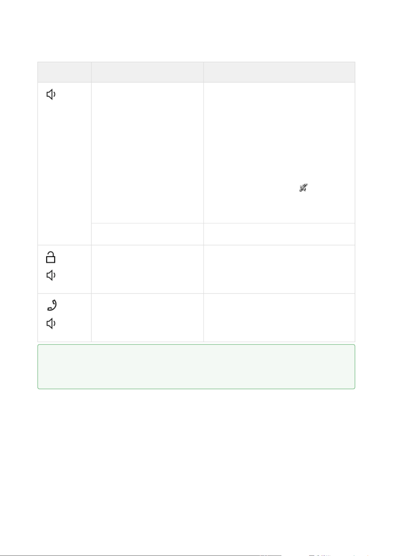
2N® Clip User Manual
55 / 75
•
•
•
•
•
Button Press type Generated action
Short press Increases volume by one level (after the
upper limit is reached, it goes to the lowest
value – value rotation)
Upon a volume level change, the device
plays the new volume level sound. The
sound signaling is shown as a percentage
on the display.
The volume level is the same for all states
and sounds.
When the lowest volume level is selected
(mute), the
mute signaling is
displayed in all states except for the Idle
mode.
Long press The Ringtone Setting menu is displayed.
and
Simultaneous long press of
both buttons
Activates/deactivates the Device Lock.
and
Simultaneous long press of
both buttons
The Settings Menu is displayed.
The button control may be different in different operational states or menus of the device. Refer
to the descriptions of the states and menus below for more information on the button actions:
Settings,
Ringtone Setting Menu,
Calls,
At Relax,
Device Lock.
Tip
Check Start call with a short press to set device A and check Start call with a long press to
set device B in the Device web configuration.
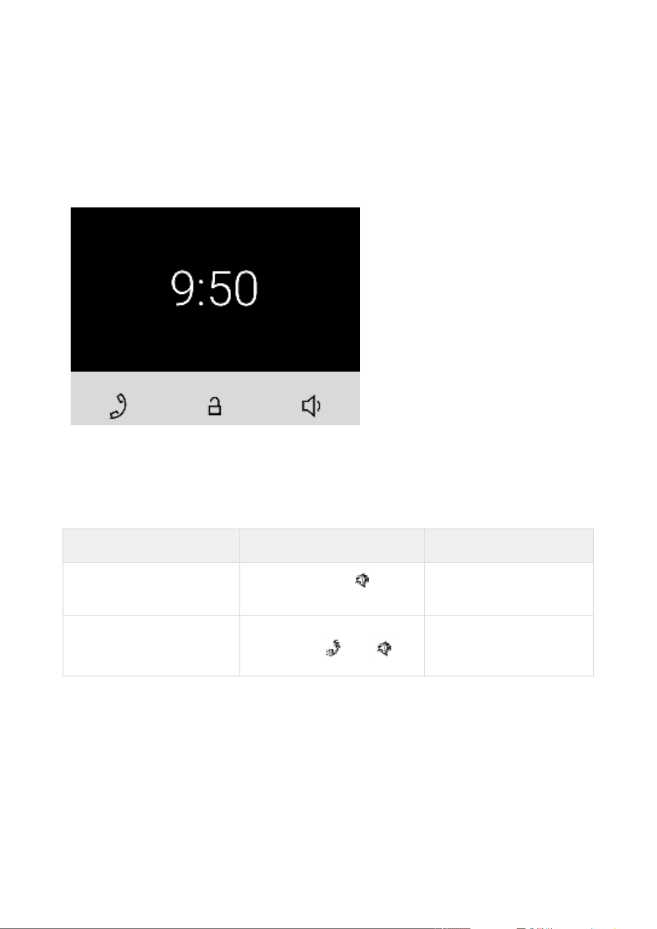
2N® Clip User Manual
56 / 75
•
•
•
6.2 Home Screen
The home screen is set as the introductory screen of the device, which is displayed whenever a
button is pressed in the Idle mode after device activation. Its appearance depends on the device
configuration, see below. The device displays time format as set in the web configuration menu
5.2.7.2 Display – 12 or 24 h.
It is possible to activate the device lock from this state.
The home screen provides access to:
Ringtone Setting Menu,
Directory Menu,
Settings Menu.
Possible actions Performance Action result
Display of Ringtone Setting
menu
Long Button Press
The Ringtone Setting menu
is displayed.
Display of Settings menu Simultaneous long press of
both buttons and
The Settings Menu is
displayed on the device.
6.2.1 Directory Menu
If 2 or more devices are added to 2N
®
Clip, the Directory menu is displayed as introduction
instead of the home screen.
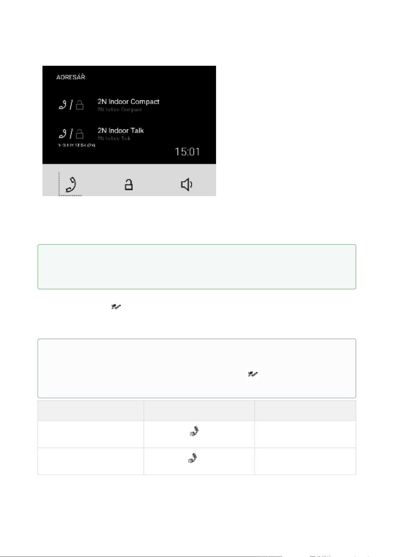
2N® Clip User Manual
57 / 75
The Directory menu allows 2 devices to be displayed: device A and device B. See the note below
for how to set the devices displayed. If there are more than 2 devices in the Directory, or more
than 2 are selected for display, they are arranged in the order and then alphabetically. If a group
of devices is to be displayed, the name and icon of the first device on the list is used for display.
The Directory menu includes a list of devices and available actions. If a call is missed from a
displayed device, the
icon appears at the respective device. The icon disappears when any
action is performed from the home screen.
The Directory menu provides all the actions listed in the Home Screen subsection.
Possible actions Performance Action result
Outgoing call to device A
Short press
Call to device A is started.
Outgoing call to device B
Long press
Call to device B is started.
Tip
Check Start call with a short press to set device A and check Start call with a long press to
set device B in the Device web configuration.
Note
If just 1 device is added, the Directory menu does not replace the introductory screen of
the device. If a call is missed from a displayed device, the
icon appears next to the
time value.
The icon disappears when any action is performed from the home screen.
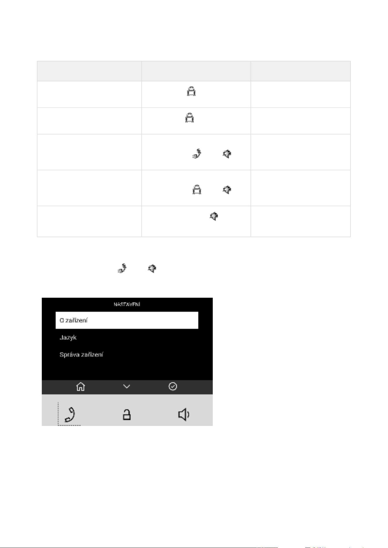
2N® Clip User Manual
58 / 75
Possible actions Performance Action result
Device A unlocking
Short press
Device A lock is unlocked.
Device B unlocking
Long press
Device B lock is unlocked.
Display of Settings menu Simultaneous long press of
both buttons and
The
Settings Menu is
displayed on the device.
Device lock activation Simultaneous long press of
both buttons and
The Device lock is
activated.
Display of Ringtone Setting
Menu
Long Button Press
The Ringtone Setting Menu
is displayed.
6.2.2 Settings Menu
After a long press of the and buttons, the home screen displays the Settings menu.
The Settings menu helps you set the device locally and contains a context menu in the bottom
part, which is controlled using the device buttons.
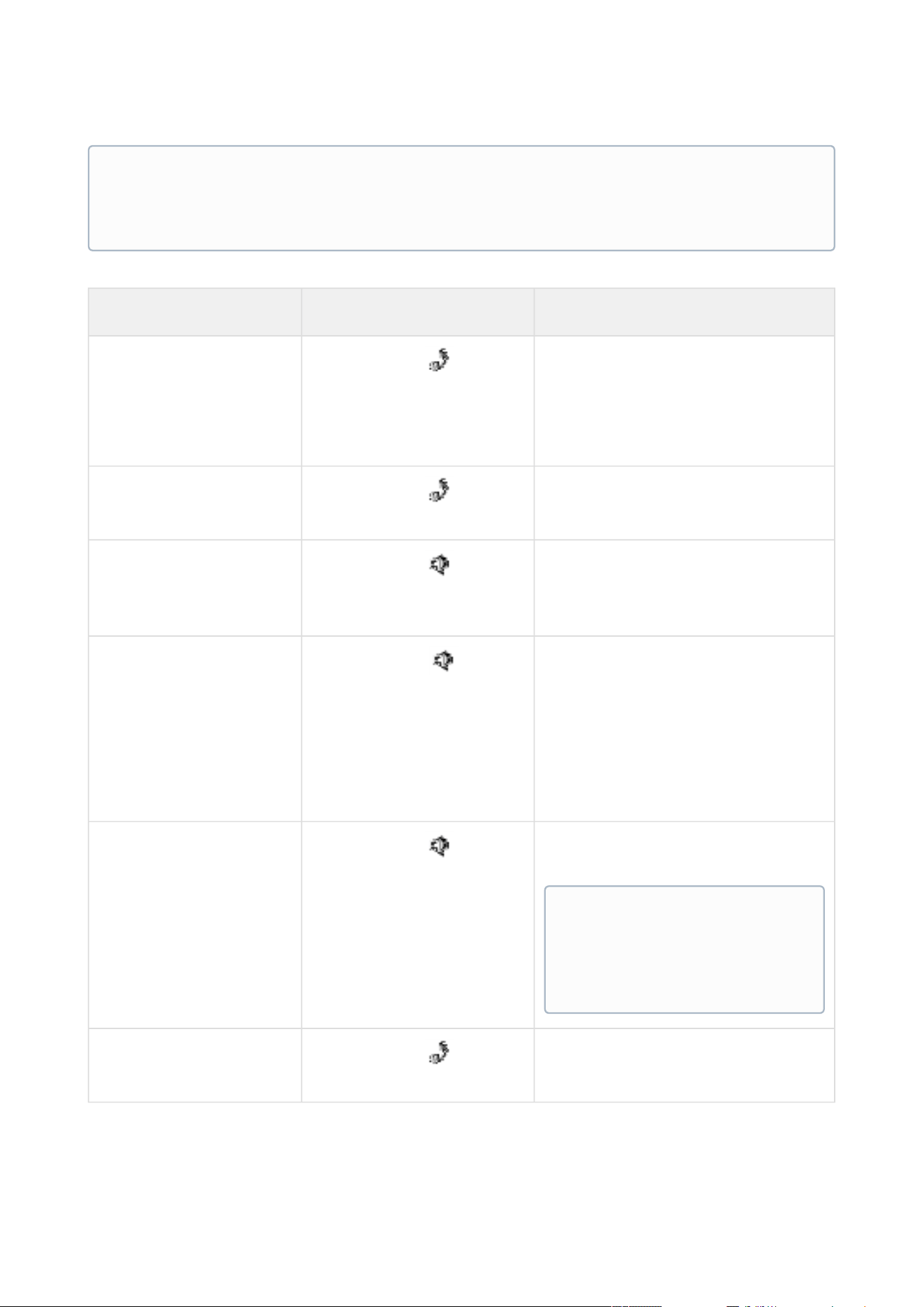
2N® Clip User Manual
59 / 75
Possible actions Performance Action result
Return to home screen
Short press of
or in 10 seconds without
any button press
or after a call.
The selection is cancelled and the
menu actions are terminated
without saving.
Back (return to
preceding action)
Short press of
Navigation to the preceding menu
section.
Selection confirmation
Short press of
Confirmation of the selected setting
option or transition to the selected
menu section.
Move to next action
Short press of
Movement by one position down in
the setting.
The movement is signaled with a
white box highlighting the current
position. When the list end is
reached, the first position is moved
onto.
Device restart
confirmation
Short press of
Device is restarted. The home
screen is displayed after restart.
Quit device restart
dialog
Short press of
Navigation to the preceding menu
section.
Note
Use the 5.2.7.2 Display menu in the web configuration to block the access to the menu.
At that moment, the device can be only be configured by software or remote access.
Note
Restarting may take a rather
long time after the button
press.
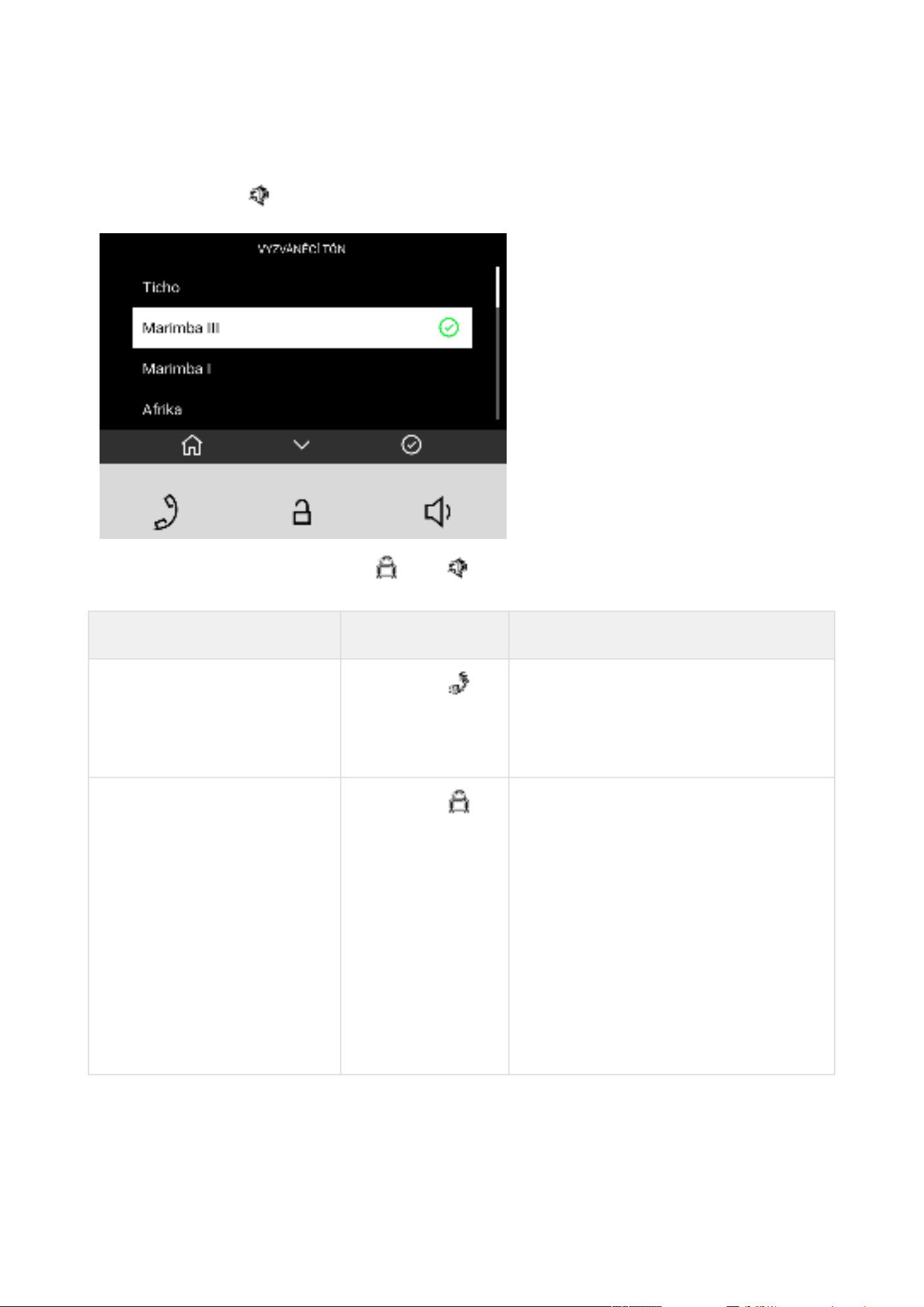
2N® Clip User Manual
60 / 75
6.2.3 Ringtone Setting Menu
A long button press displays the ringtone list.
A simultaneous press of the buttons and for 3 seconds puts the device in the Ringtone
Setting menu.
Possible actions Performance Action result
Cancel selection and return
to home screen
Short press
The selection is cancelled and the
menu actions are terminated without
saving.
Home screen is displayed.
Move to next ringtone
Short press
Movement by one position down in the
setting.
The movement is signaled with a white
box highlighting the current position.
When the list end is reached, the first
position is moved onto.
The selected ringtone position is white
highlighted in the list. When the list
end is reached, the first position is
moved onto.
Ringtone examples are played during
the movement in the settings.
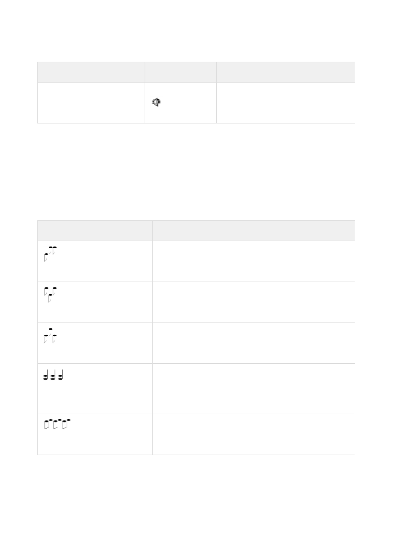
2N® Clip User Manual
61 / 75
Possible actions Performance Action result
Selection confirmation Short Press
The selection is confirmed.
The device sets the selected ringtone.
Home screen is displayed.
6.3 Operational Statuses
This section includes a basic description of user scenarios and states that can occur during the
use of 2N
®
Clip, a list of user options in variable states and expected results of these actions.
6.3.1 Signaling of Operational Statuses
The device generates sounds to signal changes of and switching between operational statuses.
Each status change is assigned a different type of tone. See the table below for the list of signals.
Sound signaling State
Internal application started.
The internal application is launched after the power
supply is turned on or the device is restarted.
Connected to the LAN, IP address received.
Once the internal application is started, the device log in
to the LAN.
Disconnected from the LAN, IP address lost.
Whenever the UTP cable is disconnected from the device,
the device loses its LAN connection.
Invalid phone number or invalid switch activation
code.
The device al;lows you to enter the door opening code.
This tone signals that invalid values have been entered.
Reset of network parameters.
Upon power up, the network parameters can be changed
by hardware, refer to
Basic Configuration Using Hardware.
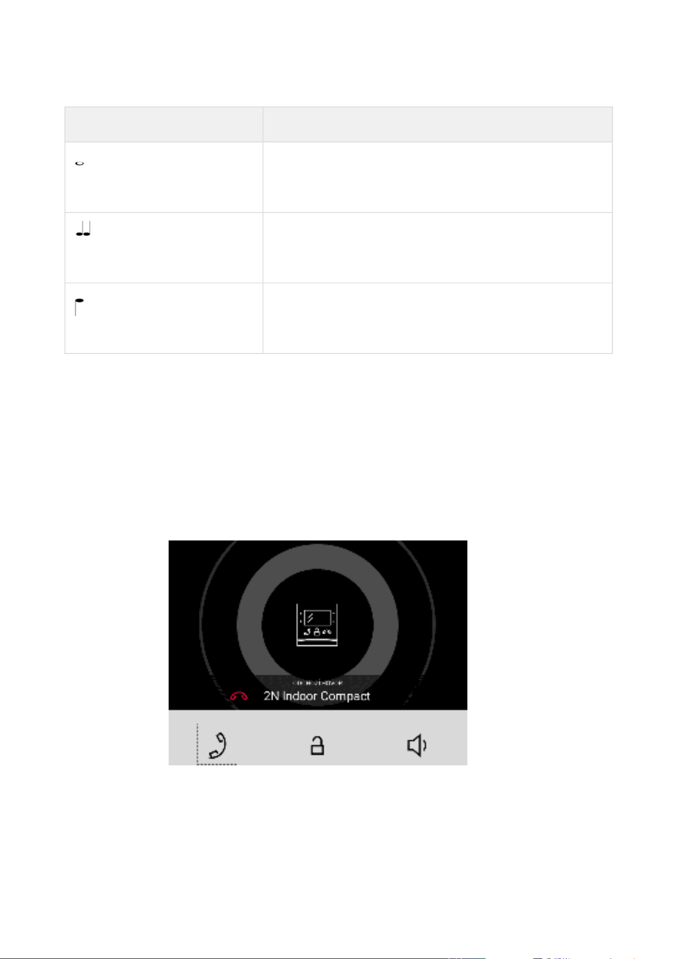
2N® Clip User Manual
62 / 75
•
•
Sound signaling State
Approaching call end signaling.
The device allows you to set a call end timeout, refer to
General Settings.
Call extension confirmation signaling.
A call can be extended by pressing a key on the VoIP
phone.
Connected call from a VoIP phone to the device.
A short tone is played to signal that the VoIP call has been
connected to the device.
6.3.2 Calls
In this state, connection or connection attempt is in progress with another device. The 2N
®
Clip
functions are limited, it is impossible to switch to the home page and go to menus. See the table
below for possible actions.
The display shows the camera preview if available in the LAN.
In this state, one of the following call types can be made:
Outgoing call initiated by the 2N
®
Clip answering unit
Incoming trying to establish connection with the 2N
®
Clip answering unit
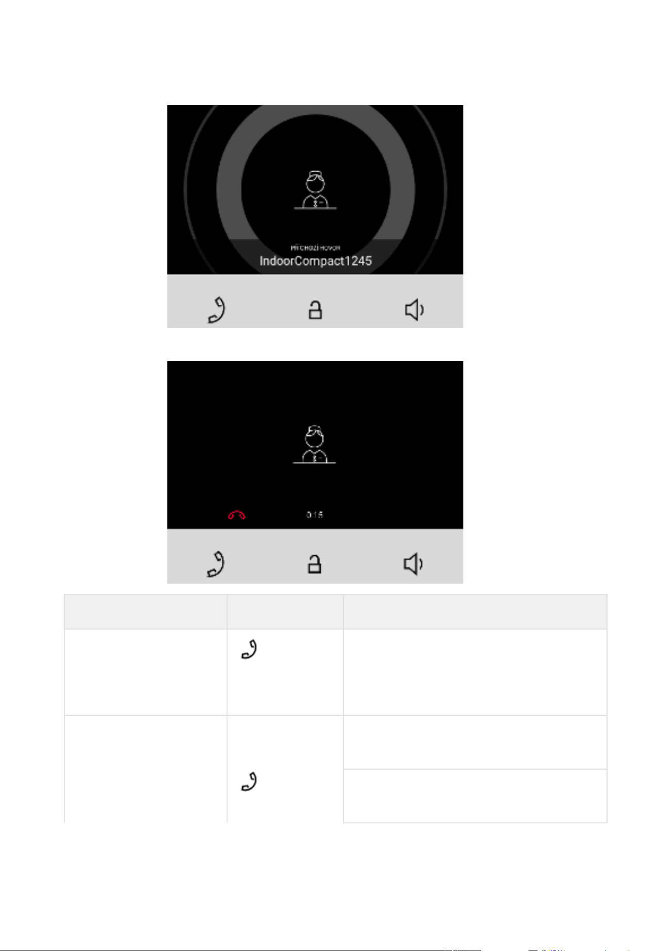
2N® Clip User Manual
63 / 75
Active call if the connection is established, sound is transmitted.
Possible actions Performance Action result
Incoming call receiving Active call, connection with the other device
established.
The call cannot be terminated until picked
up.
End of call Outgoing call cancelled.
Home screen is displayed.
Incoming call rejected.
Home screen is displayed.

2N® Clip User Manual
64 / 75
Possible actions Performance Action result
Active call interrupted.
Home screen is displayed.
Target device lock
opening
A specifically configured unlock code is sent
to the target device and, if the code is
compatible with the device, the target
device lock opens. If no unlock code is set,
the default unlock code is sent to the target
device.
Door unlocking is signaled by a green flash
of the lock button. After unlocking,
automatic call end can be set in the
Unlocking web configuration.
Call volume control Increases volume by one level (after the
upper limit is reached, it goes to the lowest
value – value rotation)
6.3.3 At Relax
2N
®
Clip transits into the Idle mode after a set inactivity period. Set the inactivity timeout in the
5.2.7.2 Display menu of the web configuration. The operation power consumption is reduced in
the Idle mode.
The device shows no information on the display in the Idle mode.
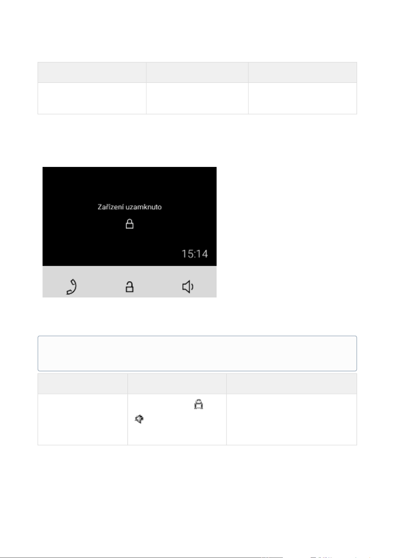
2N® Clip User Manual
65 / 75
Possible actions Performance Action result
Idle mode end Press any key
Directory Menu, Home Screen
or Device Lock is displayed.
6.3.4 Device Lock
When the lock is activated, the device rings to signal an incoming call and displays the CLIP. The
call cannot be received until the device lock is deactivated.
When the lock is activated, the device rings to signal an incoming call and displays the CLIP
including the camera preview if available. The call cannot be received until the device lock is
deactivated.
Possible actions Performance Action result
Device lock activation
Press the buttons and
for 3 seconds at the
same time
The lock is on.
Note
Set the device lock activation in the Idle mode in the web configuration Displaymenu.

2N® Clip User Manual
66 / 75
Possible actions Performance Action result
Device lock deactivation
Press the buttons and
for 3 seconds at the
same time
The device is unlocked and you can
go to other operational statuses and
perform other actions.

2N® Clip User Manual
67 / 75
7. Maintenance - Cleaning
If used frequently, the device surface gets dirty. Use a piece of soft cloth moistened with clean
water to clean the device.
You are recommended to follow the principles below while cleaning: Use appropriate
cleaning agents suitable for glasses, optical devices, screens, etc. Alcohol-based cleaners may
not be applied. We recommend that IT cleaning wipes are used.
Caution
Do not use aggressive detergents (such as abrasives or strong disinfectants).

2N® Clip User Manual
68 / 75
8. Technical Parameters
Power Supply and Input
Supply type
PoE, IEEE 802.3af, Class 0 (0,44–12,95 W)
Power Consumption
Stand-by mode with screen off 1.2 W
Stand-by mode with screen on 2.0 W
Calling without sound 2.4 W
Calling with sound 4.4 W
Calling using induction loop 6.4 W
User Interface
Control
3 capacitive buttons
Display
4" with 480 x 272 pixel resolution
Service
RESET button with long press option for factory reset
Signaling protocol
SIP
UDP, TCP, TLS
Audio
Microphone
integrated
Speaker
3 W integrated
Induction loop output
NO (the induction loop is integrated depending on
the product version).
Audiostream
Protocols
RTP

2N® Clip User Manual
69 / 75
Codecs
PCMU, PCMA, L16/16kHz, G.729, G.722
Videostream
Protocols
RTP, RTSP, HTTP
Codecs
H.264
Video Resolution
480 x 272 px
Video Framerate
up to 15 frames per s
Interface
LAN
10/100BaseT, RJ-45; Cat5e or higher
Doorbell Input
Input type
switching contact (button/relay)
Contact type
normally open (NO)
Contact parameters
min. 120 V / 20 mA, DC
Mechanical Parameters
Dimensions (w x h x d)
124 x 150 x 26 mm
Weight
295 g
Operating temperature
0 to 50 °C
Operating relative humidity
10 to 90 % non-condensing
Storage temperature
20°C to +70°C
Recommended altitude
0 to 2000 m

2N® Clip User Manual
70 / 75
•
•
•
•
•
•
•
•
•
•
9. Supplementary Information
This section provides supplementary information on the 2N
®
Clipproduct.
Here is what you can find in this section:
9.1 Troubleshooting
9.2 Directives, Laws and Regulations - General Instructions and Cautions
9.1 Troubleshooting
Refer to faq.2n.cz for the most frequently solved problems.
9.2 Directives, Laws and Regulations - General Instructions and Cautions
2N
®
Clip conforms to the following directives and regulations:
2014/35/EU for electrical equipment designed for use within certain voltage limits
2014/30/EU for electromagnetic compatibility
2011/65/EU on the restriction of the use of certain hazardous substances in electrical and
electronic equipment
2012/19/EU on waste electrical and electronic equipment
Industry Canada
This Class B digital apparatus complies with Canadian ICES-003/NMB-003.
FCC
This equipment has been tested and found to comply with the limits for a Class B digital device,
pursuant to part 15 of the FCC Rules.
NOTE: These limits are designed to provide reasonable protection against harmful interference
in a residential installation. This equipment generates, uses and can radiate radio frequency
energy and, if not installed and used in accordance with the instructions, may cause harmful
interference to radio communications.
However, there is no guarantee that interference will not occur in a particular installation. If this
equipment does cause harmful interference to radio or television reception, which can be
determined by turning the equipment off and on, the user is encouraged to try to correct the
interference by one or more of the following measures:
Reorient or relocate the receiving antenna
Increase the separation between the equipment and receiver
Connect the equipment into an outlet on a circuit different from that to which the receiver
is connected
Consult the dealer or an experienced radio/TV technician for help

2N® Clip User Manual
71 / 75
Changes or modifications to this unit not expressly approved by the party responsible for
compliance could void the user's authority to operate this equipment.

2N® Clip User Manual
72 / 75
Caution
Warning
In order to ensure the full functionality and guaranteed performance, we strongly
recommend that the topicality of the product / device version in use be verified as early
as in the installation process. The customer hereby acknowledges that the product /
device can achieve the guaranteed performance and full functionality pursuant to the
manufacturer’s instructions only if the latest product / device version is used after
having been tested for full interoperability and not having been determined by the
manufacturer as incompatible with certain versions of other products, and only in
conformity with the manufacturer’s instructions, guidelines or recommendations and in
conjunction with suitable products and devices of other suppliers. The latest versions
are available at https://www.2n.com/cs_CZ/ or can be updated via the configuration
interface if the devices are adequately technically equipped. Should the customer use a
product / device version other than the latest one or a version determined by the
manufacturer as incompatible with certain versions of other products, or should the
customer use the product / device in contradiction to the manufacturer’s instructions,
guidelines or recommendations or in conjunction with unsuitable products / devices of
other suppliers, the customer is aware of and agrees with all functionality limitations of
such a product / device if any as well as with all consequences incurred as a result
thereof. Using a product / device version other than the latest one or a version
determined by the manufacturer as incompatible with certain versions of other
products, or using the product / device in contradiction to the manufacturer’s
instructions, guidelines or recommendations or in conjunction with unsuitable
products / devices of other suppliers, the customer agrees that the 2N
TELEKOMUNIKACE a.s. company shall not be held liable for any functionality limitation
of such a product or any damage, loss or injury related to this potential functionality
limitation.

2N® Clip User Manual
73 / 75
Please read this User Manual carefully before using the product. Follow all instructions and
recommendations included herein.
Any use of the product that is in contradiction with the instructions provided herein may result
in malfunction, damage or destruction of the product.
The manufacturer shall not be liable and responsible for any damage incurred as a result of a
use of the product other than that included herein, namely undue application and disobedience
of the recommendations and warnings in contradiction herewith.
Any use or connection of the product other than those included herein shall be considered
undue and the manufacturer shall not be liable for any consequences arisen as a result of such
misconduct.
Moreover, the manufacturer shall not be liable for any damage or destruction of the product
incurred as a result of misplacement, incompetent installation and/or undue operation and use
of the product in contradiction herewith.
The manufacturer assumes no responsibility for any malfunction, damage or destruction of the
product caused by incompetent replacement of parts or due to the use of reproduction parts or
components.
The manufacturer shall not be liable and responsible for any loss or damage incurred as a result
of a natural disaster or any other unfavourable natural condition.
The manufacturer shall not be held liable for any damage of the product arising during the
shipping thereof.
The manufacturer shall not make any warrant with regard to data loss or damage.
The manufacturer shall not be liable and responsible for any direct or indirect damage incurred
as a result of a use of the product in contradiction herewith or a failure of the product due to a
use in contradiction herewith.
All applicable legal regulations concerning the product installation and use as well as provisions
of technical standards on electric installations have to be obeyed. The manufacturer shall not be
liable and responsible for damage or destruction of the product or damage incurred by the
consumer in case the product is used and handled contrary to the said regulations and
provisions.
The consumer shall, at its own expense, obtain software protection of the product. The
manufacturer shall not be held liable and responsible for any damage incurred as a result of the
use of deficient or substandard security software.
The consumer shall, without delay, change the access password for the product after
installation. The manufacturer shall not be held liable or responsible for any damage incurred by
the consumer in connection with the use of the original password.
The manufacturer also assumes no responsibility for additional costs incurred by the consumer
as a result of making calls using a line with an increased tariff.

2N® Clip User Manual
74 / 75
Electric Waste and Used Battery Pack Handling
Do not place used electric devices and battery packs into municipal waste containers. An undue
disposal thereof might impair the environment!
Deliver your expired electric appliances and battery packs removed from them to dedicated
dumpsites or containers or give them back to the dealer or manufacturer for environmental-
friendly disposal. The dealer or manufacturer shall take the product back free of charge and
without requiring another purchase. Make sure that the devices to be disposed of are complete.
Do not throw battery packs into fire. Battery packs may not be taken into parts or short-circuited
either.

2N® Clip User Manual
75 / 75