Loading ...
Loading ...
Loading ...
Installation instructions en
19
WARNING‒Risk of electric shock!
It must always be possible to disconnect the appliance
from the electricity supply. The appliance must only be
connected to a protective contact socket that has been
correctly installed.
▶ The mains plug for the mains power cable must be
easily accessible after the appliance is installed.
▶ If this is not possible, an all-pole isolating switch
must be integrated into the permanent electrical in-
stallation according to the conditions of overvoltage
category III and according to the installation regula-
tions.
▶ The permanent electrical installation must only be
wired by a professional electrician. We recommend
installing a residual-current circuit breaker (RCCB)
in the appliance's power supply circuit.
Sharp-edged components inside the appliance may
damage the connecting cable.
▶ Do not kink or trap the connecting cable.
¡ The connection data can be found on the rating
plate. →Page13
¡ The connecting cable is approx.1.30m long.
¡ This appliance complies with the EC interference
suppression regulations.
¡ The appliance corresponds to protection class 1.
You should therefore only use the appliance with a
protective earth connection.
¡ Do not connect the appliance to the power supply
during installation.
¡ Ensure that the protection against contact is guaran-
teed during installation.
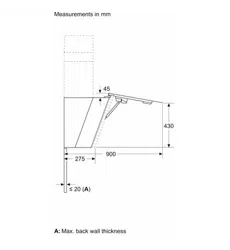
19.8 Information on the installation situation
¡ Install this appliance on the kitchen wall.
¡ The appliance must be installed before the upper
cabinets, if these are deeper than 370mm.
¡ To install additional special accessory parts, ob-
serve the enclosed installation instructions.
¡ The width of the extractor hood must correspond at
least with the width of the hob.
¡ To optimally detect the cooking vapours, install the
appliance in the middle of the hob.
19.9 Instructions for the exhaust air pipe
The appliance manufacturer does not provide any war-
ranty for faults attributable to the pipeline.
¡ Use a short, straight exhaust air pipe with as large a
pipe diameter as possible.
¡ Long, rough exhaust air pipes, many pipe bends or
small pipe diameters reduce the suction power and
increase the fan noise.
¡ Use an exhaust pipe that is made of non-combust-
ible material.
¡ To prevent condensate from returning, fit the ex-
haust pipe with a 1° gradient from the appliance.
19.10 Instructions for the air extraction
mode
For air extraction mode, a one-way flap should be in-
stalled.
Notes
¡ If a one-way flap is not included with the appliance,
one can be ordered from a specialist retailer.
¡ If the exhaust air is conveyed through the external
wall, a telescopic duct should be used.
19.11 Installation
Checking the wall
1.
Check whether the wall is horizontal and adequately
load-bearing.
The maximum weight of the appliance is 30kg.
2.
Drill the hole depth in accordance with the length of
the screws.
3.
Use the enclosed screws and wall plugs.
The enclosed screws and wall plugs are suitable for
use with solid brickwork. Use suitable fixing material
for other structures, e.g. plasterboard, porous con-
crete, poroton bricks.
4.
Install the appliance with a fixing material which is
sufficiently stable and has been adjusted accord-
ingly for both the structural conditions and the
weight of the appliance.
5.
Check the cut-out area for existing cables of other
appliances.
Preparing the wall
1.
Observe the information on the installation situation.
→Page19
2.
Ensure that there are no electrical wires, gas pipes
or water pipes in the area where holes are to be
drilled.
3.
Cover the hob to prevent damage.
4.
Determine the position of the extractor hood and
lightly mark where the lower edge of the appliance
should be on the wall.
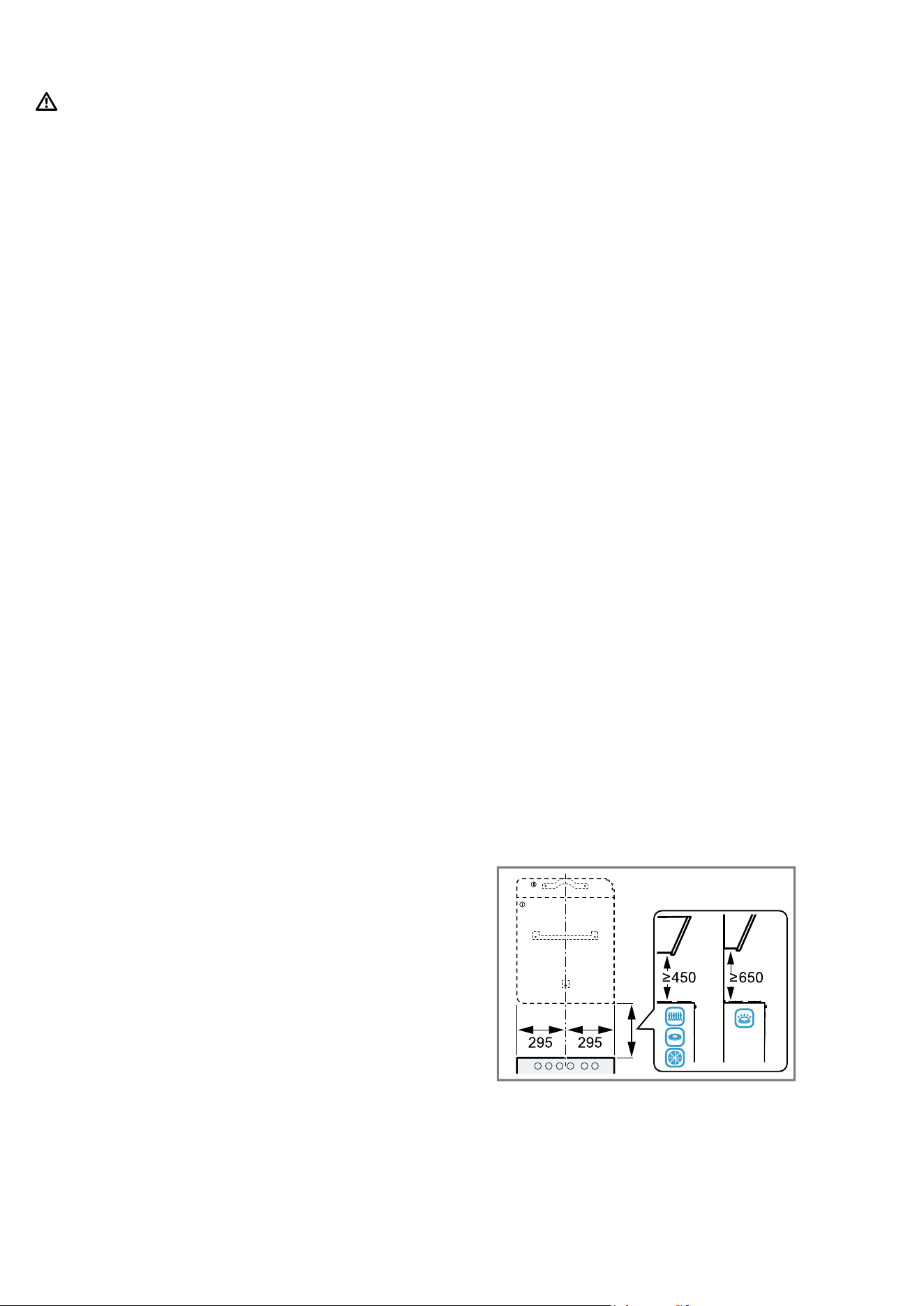
‒ Determine the centre of the hob.
‒ Comply with the safety clearances for the hob.
We recommend fitting the extractor hood in such a
way that the lower edge of the glass screen is in
line with the lower edges of the adjacent wall-hung
cabinets.
5.
To make the installation easier, apply and secure
the packaging section that is used as the template
to the line that is marked out.
6.
Mark the positions for the screws.
7.
For the installation with the flue cover, separate the
template along the marked cut line.
8.
Place the detached part at the required position.
Observe the entire length of the flue duct.
9.
Drill the 8mmdiameter holes to a depth of 80mm
for the fastenings.
10.
Remove the template.
Loading ...
Loading ...
Loading ...