
Installation Plan
Vented Dryer
PDR 908 EL
INDUSTRIAL USE ONLY
Always read the operating and installation instructions before
setting up, installing, and commissioning the machine.
This prevents both personal injury and damage to the machine.
en-US
11 278 890/06

2 11 278 890/06
Please have the model and serial number of your machine available when contacting Technical Service.
U.S.A.
Miele, Inc.
National Headquarters
9 Independence Way
Princeton, NJ 08540
Phone: 800-991-9380
www.mieleusa.com/professional
Technical Service & Support
Phone: 800-991-9380
Miele & Cie. KG
Carl-Miele-Straße 29, 33332 Gütersloh, Germany
Legend:
Connection required
Connection optional or required,
depending on model
AL
Vented
KLZ
Cooling air intake
ASK
Condensate drain hose
PA
Equipotential bonding and grounding
B
Machine anchoring
SLA
Peak-load connection
EL
Electrical connection
APCL SST
Closed plinth
F
Machine feet, adjustable
APCL OB
Open plinth
KG
Payment system
APCL 001
Washer-dryer stacking kit
KGA
Payment system connection
XKM
Communication module
KLA
Cooling air vent
ZL
Air intake
All rights reserved.
PDR 908 EL en-US
11 278 890/06 3
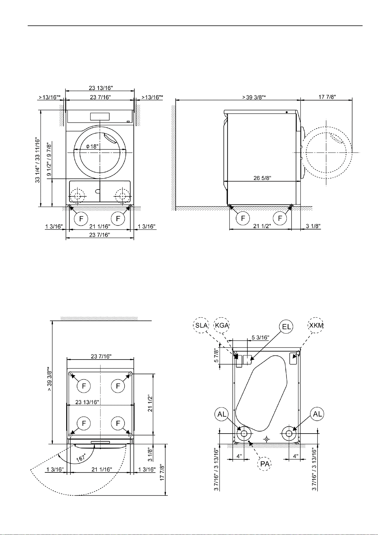
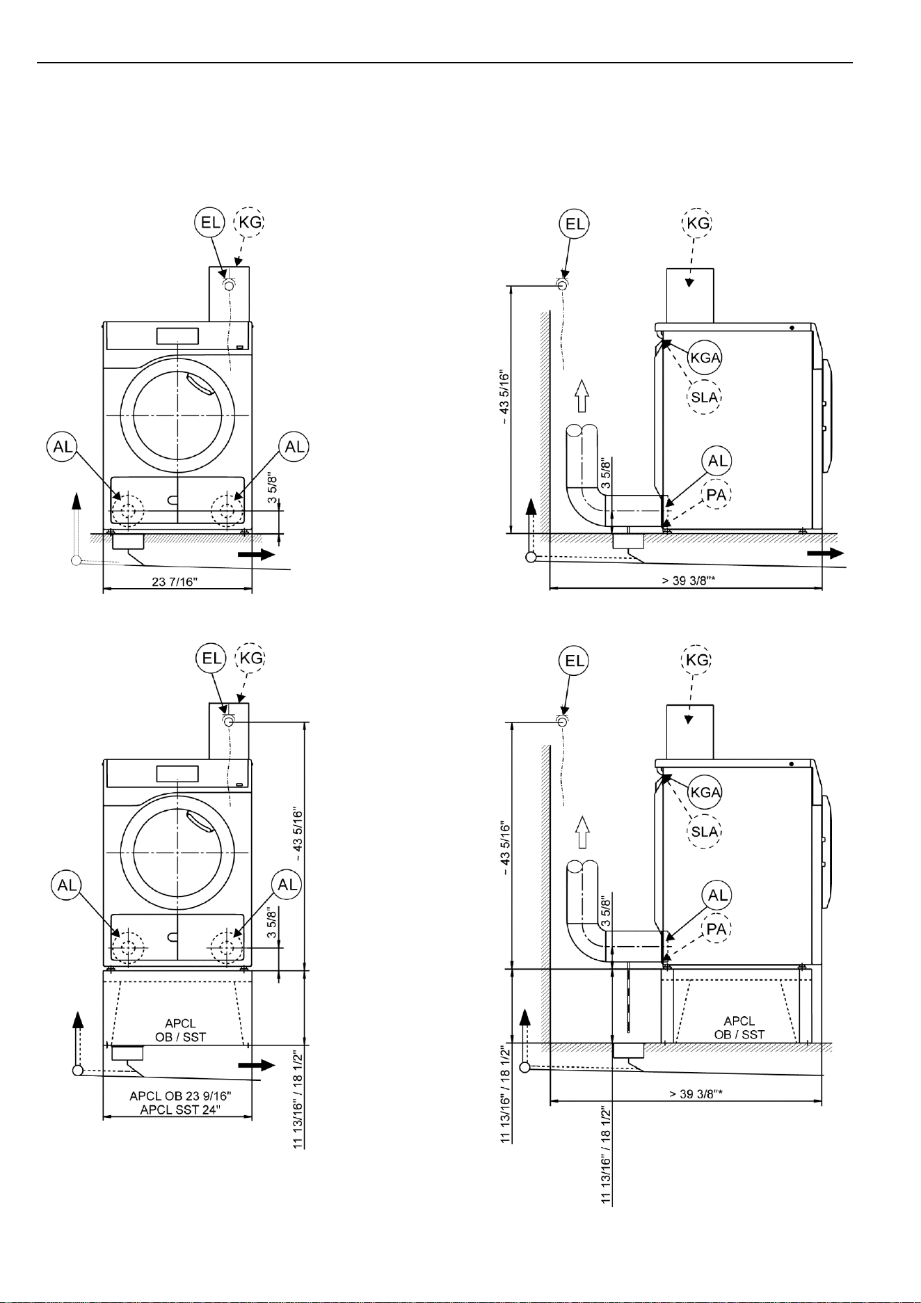
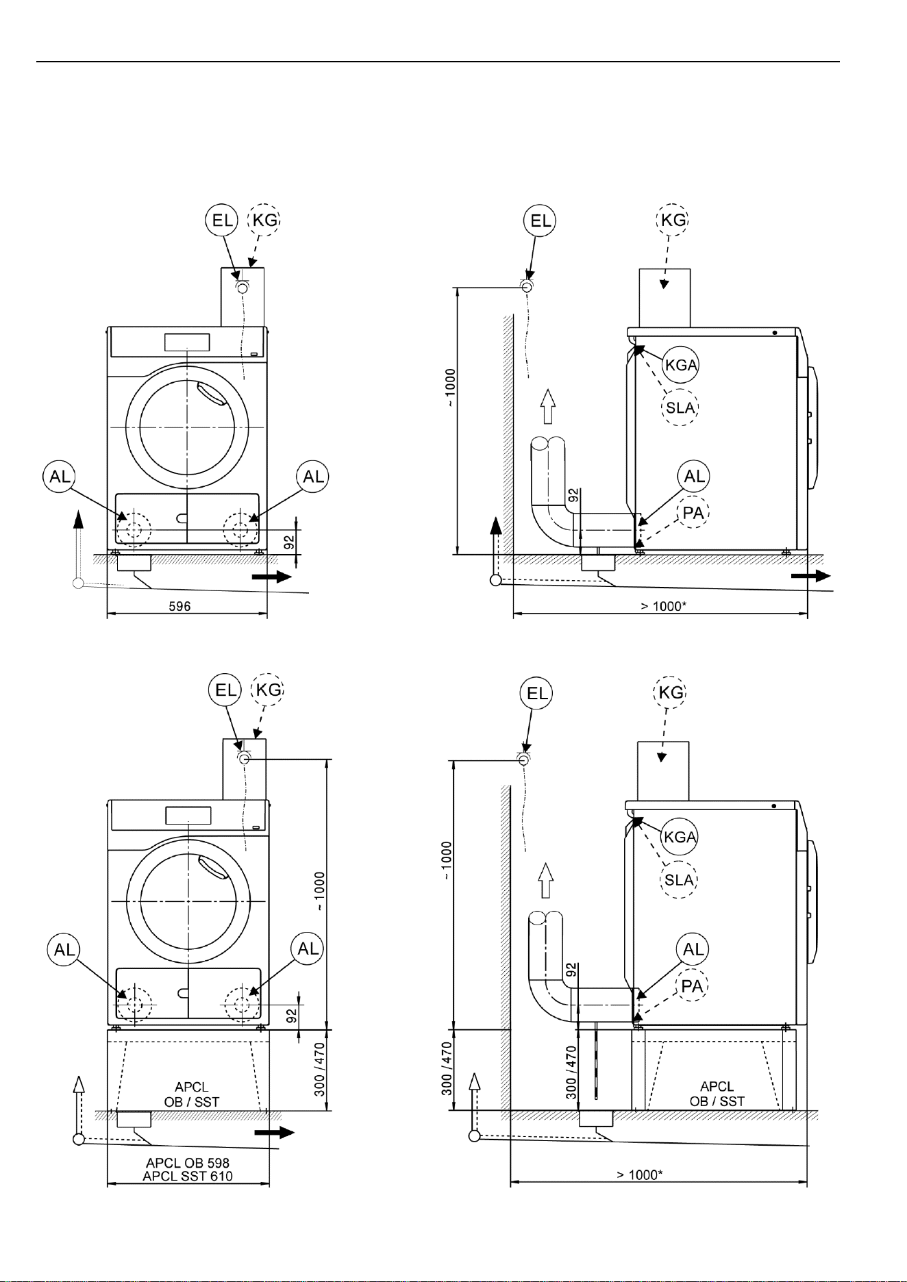
Machine dimensions -measurements in inches-
* The distances between the machine and the wall are recommendations to help make it easier to carry out service
work. If installation space is limited, the machine can also be pushed up against the wall.
PDR 908 EL en-US
4 11 278 890/06
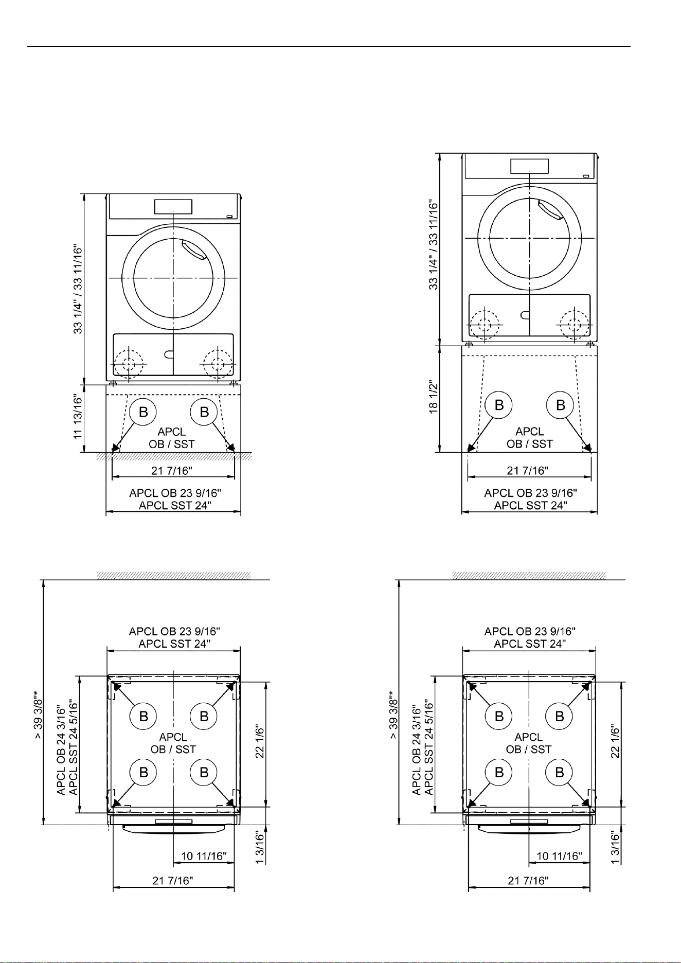
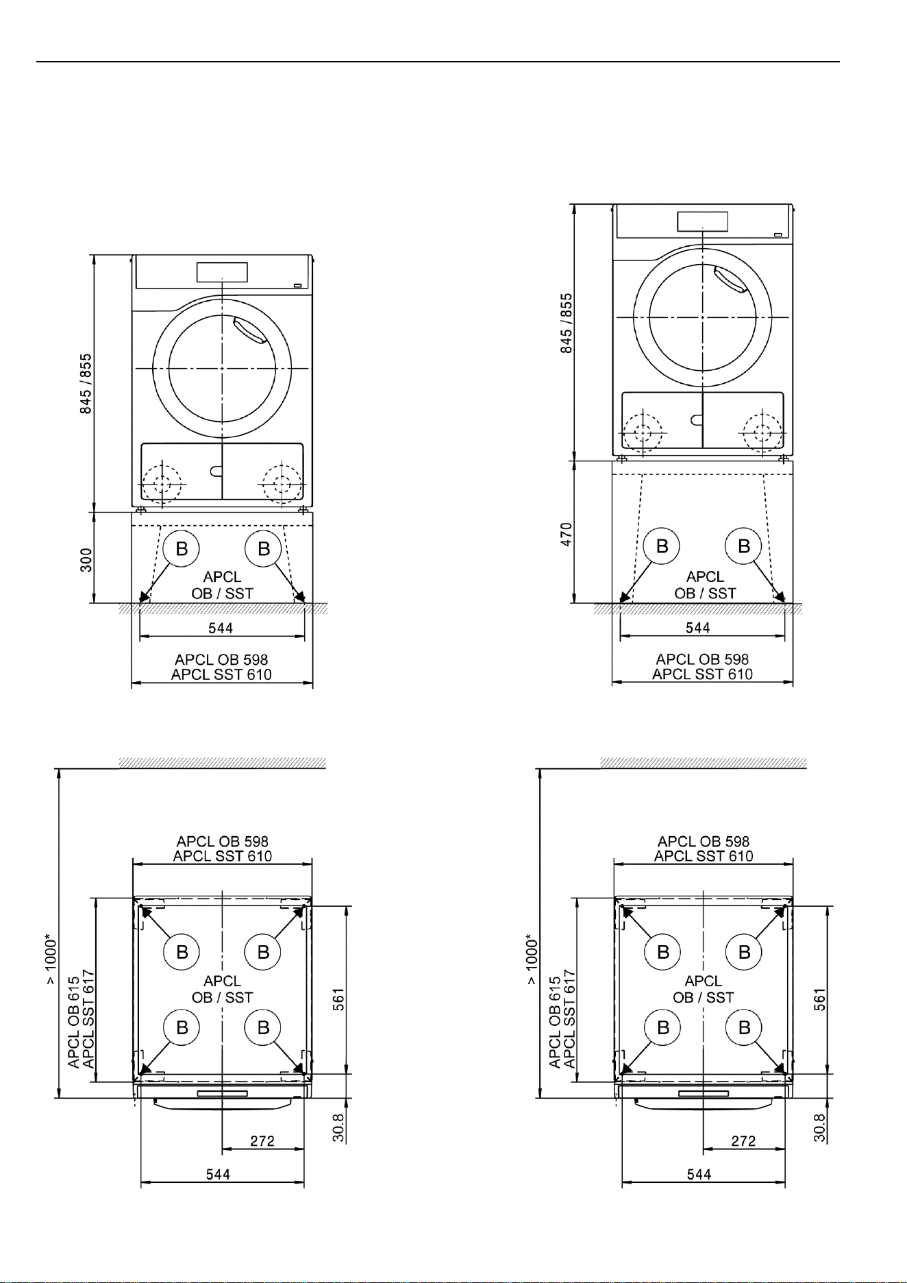
Installation -measurements in inches-
* The distances between the machine and the wall are recommendations to help make it easier to carry out service
work. If installation space is limited, the machine can also be pushed up against the wall.
PDR 908 EL en-US
11 278 890/06 5
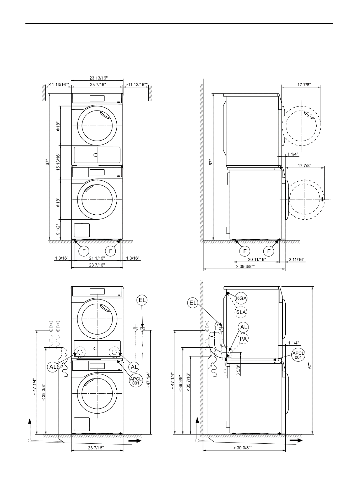
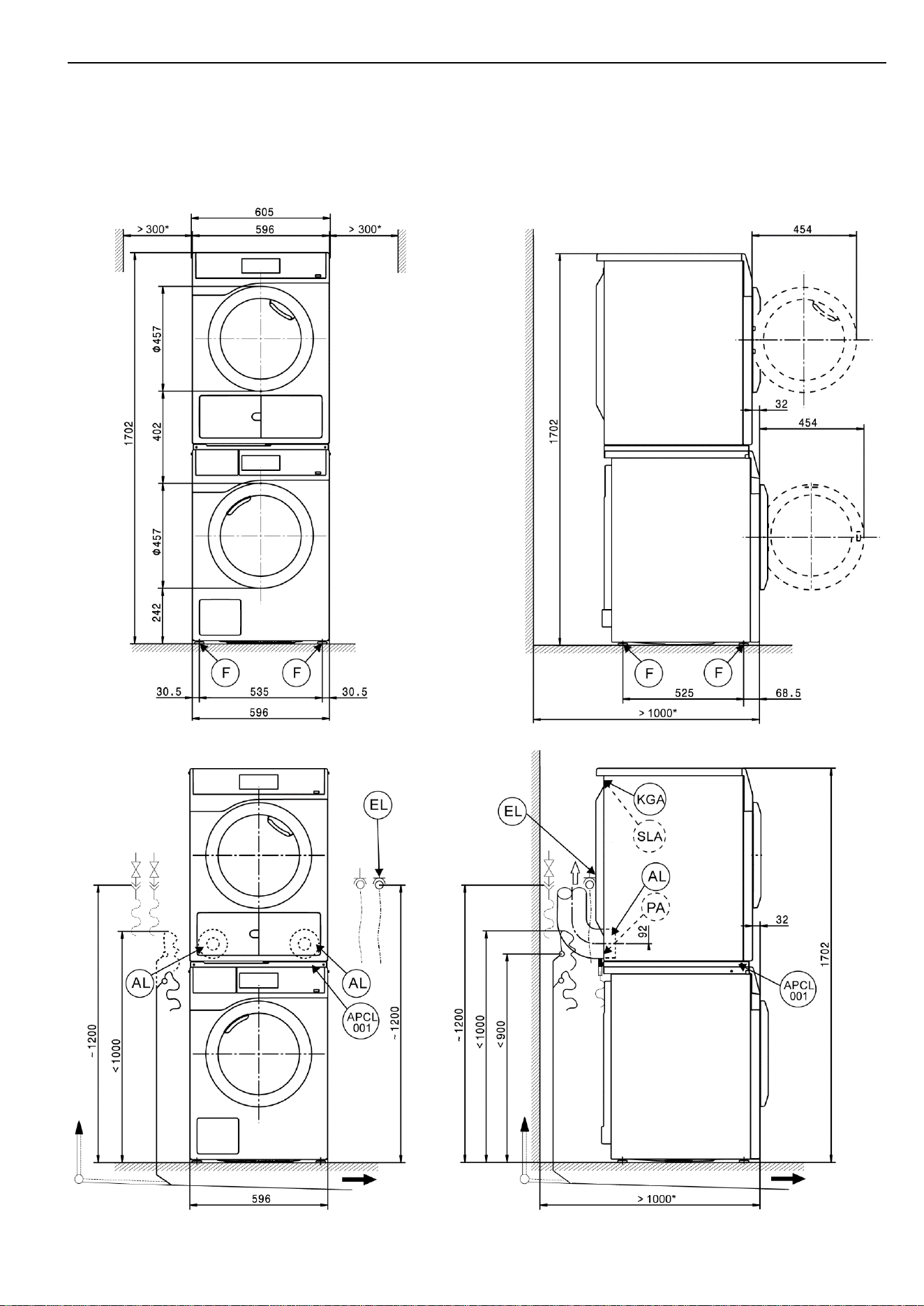
Washer-dryer stack -measurements in inches-
* The distances between the machine and the wall are recommendations to help make it easier to carry out service
work. If installation space is limited, the machine can also be pushed up against the wall.
PDR 908 EL en-US
6 11 278 890/06
Installation -measurements in inches-
* The distances between the machine and the wall are recommendations to help make it easier to carry out service
work. If installation space is limited, the machine can also be pushed up against the wall.
PDR 908 EL en-US
11 278 890/06 7
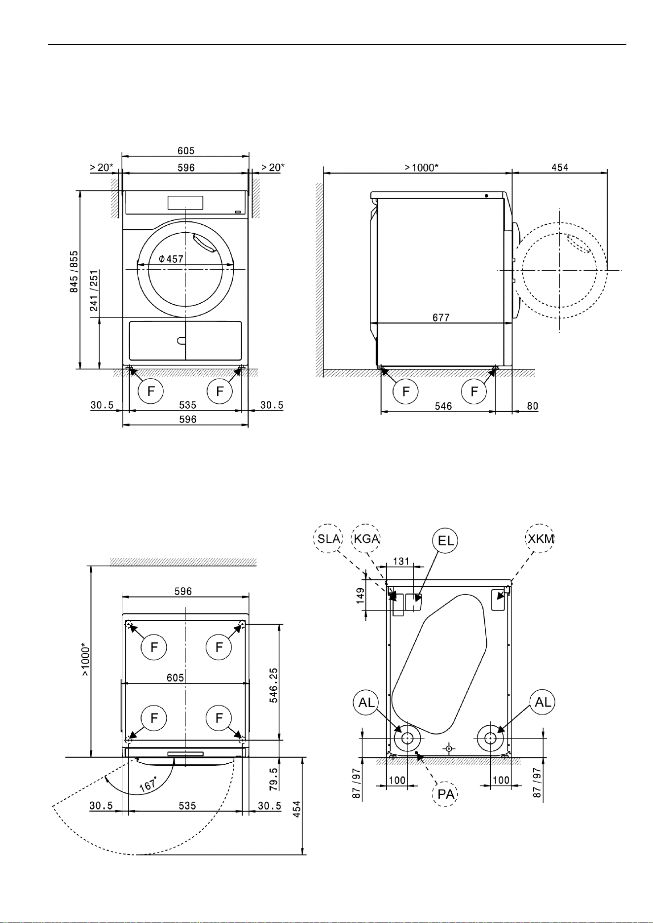
Machine dimensions -measurements in millimeters-
* The distances between the machine and the wall are recommendations to help make it easier to carry out service
work. If installation space is limited, the machine can also be pushed up against the wall.
PDR 908 EL en-US
8 11 278 890/06
Installation -measurements in millimeters-
* The distances between the machine and the wall are recommendations to help make it easier to carry out service
work. If installation space is limited, the machine can also be pushed up against the wall.
PDR 908 EL en-US
11 278 890/06 9
Washer-dryer stack -measurements in millimeters-
* The distances between the machine and the wall are recommendations to help make it easier to carry out service
work. If installation space is limited, the machine can also be pushed up against the wall.
PDR 908 EL en-US
10 11 278 890/06
Installation -measurements in millimeters-
* The distances between the machine and the wall are recommendations to help make it easier to carry out service
work. If installation space is limited, the machine can also be pushed up against the wall.

PDR 908 EL en-US
= standard, = optional, + = only on request, - not available
11 278 890/06 11
Technical data
PDR 908 EL
PDR 908 EL
Drying system
Vented
Vented
Drum volume
34.3
gal
130
l
Capacity
17.6
lb
8.0
kg
Door opening diameter
14 9/16"
370
mm
Electrical connection (EL)
Standard voltage for CDN & USA
2 AC 208–240 V
2 AC 208–240 V
Frequency
60
Hz
60
Hz
Total rated load
3.2/4.3
kW
3.2/4.3
kW
Fuse rating
2 x 30
A
2 x 30
A
Wire min. cross-section
3 x AWG10
3 x AWG10
Wire with plug NEMA L6–30
Wire length
72"
1,830
mm
Non-standard voltage MAR 208–240 (Marine)
2 AC 208–240 V
2 AC 208–240 V
Frequency
60
Hz
60
Hz
Total rated load
3.2/4.3
kW
3.2/4.3
kW
Fuse rating
2 x 30
A
2 x 30
A
Wire min. cross-section
3 x AWG10
3 x AWG10
Wire with plug NEMA L6–30
Wire length
72"
1,830
mm
Vented (EL)
Connector (ext. diameter)
4"
100
mm
Max. vented air temperature
175
°F
80
°C
Electrical connection with 50 Hz/60 Hz
Max. permissible pressure loss
340
Pa
340
Pa
Max. flow rate w/o counterpressure (0 Pa) in vented mode
10064
cfh
285
m³/h
Potential equalization (PA)
Machine connection (with installation kit)
XCI-Box interface
Peak load/Energy management (SLA)
Machine connection (with XCI-Box)
Communication module (XKM)
Communication module XKM 3200 WL PLT
Installation on machine feet (F)
No. of machine feet
4
No.
4
No.
Machine foot, height-adjustable with thread
± 3/16"
± 5
mm
Machine foot diameter
1 1/4"
31.7
mm
Anchoring (B)
Anchoring of Miele Plinths
Miele Plinth installation (fasteners included)
Required anchor points
4
No.
4
No.
Wood screws according to DIN 571
8 x 65
mm
8 x 65
mm
Rawl plugs (diameter x length)
12 x 60
mm
12 x 60
mm
Plinth floor anchoring (to be provided on site)
Machine installation on on-site plinth (concrete or masonry)
Min. plinth installation footprint (W/D)
23 5/8" / 25 9/16"
600/650
mm
Wood screws according to DIN 571
6 x 50
mm
6 x 50
mm
Rawl plugs (diameter x length)
8 x 40
mm
8 x 40
mm

PDR 908 EL en-US
= standard, = optional, + = only on request, - not available
12 11 278 890/06
Technical data
PDR 908 EL
PDR 908 EL
Machine data
Overall machine dimensions (H/W/D)
33 7/16" / 23 13/16" / 28 1/4"
850/605/717
mm
Casing dimensions (H/W/D)
33 7/16" / 23 7/16" / 26 5/8"
850/596/677
mm
Site-access dimensions (H/W)
Min. site-access opening (excl. packaging)
35 7/16" / 23 13/16"
900/605
mm
Installation dimensions
Side gap
13/16"
20
mm
Recommended side gap – washer-dryer stack
11 13/16"
300
mm
Recommended distance to opposite wall from front of machine
39 3/8"
1,000
mm
Weights and floor loads
Machine weight (net weight)
114
lb
51.5
kg
Max. floor load in operation
670
N
670
N
Emissions
Sound pressure level (in accordance with EN ISO 11204/11203)
<70
dB(A)
<70
dB(A)
Heat dissipation rate to installation site
200
W
200
W
PDR 908 EL en-US
11 278 890/06 13
Installation and planning notes
Installation requirements
The tumble dryer should only be connected to a power supply
provided in accordance with all appropriate local and national
legislation and regulations.
In addition, all regulations issued by the appropriate utilities as well as
standards relating to occupational safety and all applicable valid
regulations and technical standards must be observed.
General operating conditions
Ambient temperature in installation room: +35°F to +95 (+2°C to
+35°C).
Electrical connection
This tumble dryer is supplied with a power cord and plug ready for
connection.
The machine may only be connected to an electrical system that
conforms to national and local codes and regulations. This connection
must be made by a qualified electrician.
The data tag indicates the nominal power consumption and the
appropriate fuse rating. Compare the specifications on the data tag
with those of the electrical power supply.
The tumble dryer can either be hard-wired or connected using a plug-
and-socket connection in accordance with IEC 60309-1. Miele always
recommends connecting the machine via a plug and socket so that
electrical safety checks can be carried out easily (during repair or
service work, for example).
If the machine is hard-wired, a dual circuit breaker must be provided
on site. When switched off, there must be an all-pole contact gap of at
least 3 mm in the isolator switch (including circuit breakers, breakers,
and relays according to IEC/EN 60947).
The plug connector or isolator switch should be easily accessible at all
times. If the tumble dryer is disconnected from the electricity supply,
the isolator must be lockable or the point of disconnection must be
monitored at all times.
New connections, modifications to the system, or servicing of the
ground conductor, including determining the correct fuse rating, must
be carried out by a qualified electrician, as they are familiar with the
pertinent regulations and the specific requirements of the electric
utility company.
If converting the tumble dryer to an alternative voltage, observe the
instructions in the wiring diagram. Conversion must be performed
by Miele Technical Service or by an authorized Miele dealer. The
heater rating must also be adapted.
The tumble dryer must not be connected to devices such as timers
which would switch it off automatically.
References to cable cross-sections in the technical data refer only to
the required power cord. Please consult relevant local and national
regulations when calculating any other wire gauges.
Vent connection
Hot moist exhaust air should be vented to atmosphere along the
shortest possible route or connected to a suitable vent system.
Depending on the duct path, the moist exhaust air can condense on
the duct walls to a greater or lesser extent. For this reason it is
recommended to lay ducting with a downwards slope to the air exit.
If ducting slopes upwards, a condensate trap either with a drip tray or
a connection to a suitable on-site floor drain must be installed in the
system at the lowest point.
Condensate must not flow back into the machine.
It is permissible to vent exhaust air via an external wall. In this case,
measures must be taken to minimize the risk and annoyance to
neighboring buildings.
The end of exhaust air ducting leading into the open should be
protected against the elements, e.g., using a suitable hood or grille or
with a 90° bend.
The cross-sectional area of the ducting must not be reduced or
obstructed by built-in parts. Filters and louvers must not be installed in
the ducting.
Congestion in the line may lead to a drop in machine performance or
to machines being switched off to guarantee safety.
Proper functioning of the tumble dryer cannot be guaranteed if the
max. permissible pressure loss is exceeded in the on-site vent
ducting system.
When connecting several tumble dryers to a common duct, the cross-
sectional area of the duct must be increased accordingly.
Additionally, in such a case every tumble dryer must have its own
non-return valve to prevent dryers affecting others in the system. This
requires the provision of on-site additional parts.
In the event that exhaust air ducts from several tumble dryers are
merged into a common duct, a non-return device should be
installed in each separate line to prevent backflow.
With complex ducting with many bends and additional components, or
with the connection of several different machines to a common duct, it
is recommended that a detailed calculation is carried out by a suitable
specialist.
Air intake
The air supply for the tumble dryer is taken directly from the
installation site.
During operation, adequate ventilation of the installation site should be
guaranteed. Depending on the machine version, it is necessary to
ensure an intake of fresh air to compensate for the volume of exhaust
air extracted in order to avoid the creation of a vacuum.
It should not be possible to close or otherwise obstruct air intake
grilles or alternative measures should be implemented to ensure that
an adequate supply of fresh air is available at all times during tumble
dryer operation.
Equipotential bonding and grounding
If necessary, an equipotential bond with good contact connection must
be provided in accordance with all appropriate national and local
regulations.
Connection material for equipotential bonding and grounding must be
provided on site or using a kit available from Miele Technical Service.
Peak load/Energy management
The machine can be connected to a peak-load or energy-
management system using an optional kit.
When the peak-load function is activated, the heating is deactivated.
A message appears in the display to inform you of this.

PDR 908 EL en-US
14 11 278 890/06
Interface
The tumble dryer can be installed with an XKM 3200 WL PLT
communication module.
This module can be used as a WiFi or LAN interface.
The LAN interface provided via the module complies with SELV
(Safety Extra Low Voltage) in accordance with EN 60950. Connected
appliances must also comply with SELV. The LAN connection uses a
RJ45 connector in accordance with EIA/TIA 568-B.
Installation and anchoring
The machine must be installed on a perfectly smooth, level, and firm
surface which is able to withstand the quoted loads.
The floor load created by the appliance is concentrated and
transferred to the installation footprint via the machine feet.
The tumble dryer should be leveled in both directions with the aid of
the adjustable feet.
Plinth installation
The tumble dryer can be installed on a machine plinth (open or box
plinth, available as an optional Miele accessory) or on a concrete
plinth to be provided on site.
The quality of the concrete and its strength must be assessed
according to the machine load. Ensure that any raised concrete plinth
is adequately bonded to the floor below.
Washer-dryer stack
The tumble dryer can be installed as a washer-dryer stack together
with a Miele Washing Machine. A stacking kit (optional accessory)
is required for this.
Installation of the stacking kit should be performed by Miele Technical
Service or an authorized Miele service technician.