Thank you for purchasing a Sealey product. Manufactured to a high standard, this product will, if used according to these
instructions, and properly maintained, give you years of trouble free performance.
IMPORTANT: PLEASE READ THESE INSTRUCTIONS CAREFULLY. NOTE THE SAFE OPERATIONAL REQUIREMENTS, WARNINGS & CAUTIONS. USE
THE PRODUCT CORRECTLY AND WITH CARE FOR THE PURPOSE FOR WHICH IT IS INTENDED. FAILURE TO DO SO MAY CAUSE DAMAGE AND/OR
PERSONAL INJURY AND WILL INVALIDATE THE WARRANTY. KEEP THESE INSTRUCTIONS SAFE FOR FUTURE USE.
1. SAFETY
WARNING! Ensure any Health & Safety, Government, or local authority regulations are adhered to when using this equipment.
9 Familiarise yourself with the application and limitations, as well as the potential hazards, of the generator.
9 Maintain the generator in good condition (use an authorised service agent). Replace or repair damaged parts. Use genuine parts only
Unauthorised parts may be dangerous and will invalidate the warranty.
9 This generator is designed and manufactured for specific applications. DO NOT attempt to modify the unit or use it for any application for
which it is not designed. If you have any questions regarding the application of the unit please contact your local Sealey dealer.
WARNING! DO NOT exceed the Wattage/Amperage capacity of the generator. Add rated wattage of all devices intended for
connection at any one time, the total must not exceed rated wattage of generator (see specifications).
WARNING! Generator exhaust gases contain deadly carbon monoxide which must not be inhaled. Always allow sufficient
ventilation.
WARNING! If you decide to use an Earth Leakage Circuit Breaker (also referred to as an RCD or Ground Fault Circuit Interrupter), it
is imperative that the neutral end of the power winding is connected to the frame of the generator set and that the earth lug on the frame is
connected with a low impedance connector to the local earth via an earth spike or local protective earth conductor. This connection should
only be attempted by a qualified electrician, after first having consulted your local stockist.
▲ DANGER! This generator is designed for outdoor use only. To use the generator inside any building or enclosure, including the generator
compartment of a caravan, may result in fire or an explosion. No user performed modifications, including venting of the exhaust and/or
cooling ventilation, will eliminate the danger.
▲ DANGER! If this unit is used for back-up power in the event of a commercial power failure, the following steps must be taken. Before
connecting the generator to the electrical system, open the main circuit breaker to isolate the generator and system from the commercial
electric supply. Failure to do this may result in damage to the generator and may result in serious injury or fatality, due to a back-feed of
electrical energy.
▲ DANGER! The generator produces a very powerful voltage that can cause a severe electrical shock. Avoid contact with bare wires,
terminals etc. Never allow any unqualified person to operate or service the generator.
WARNING! Petrol is highly flammable and petrol vapour is explosive. DO NOT permit smoking, naked flames, sparks or heat in the
vicinity while handling petrol. Avoid spilling petrol onto a hot engine. Comply with all laws regulating storage and handling of fuels.
WARNING! NEVER refuel when the engine is running or when the engine is hot. Allow cool down time.
9 Operate the generator only on level surfaces (maximum allowable tilt is 10º) and where it will not be exposed to excessive moisture, dirt
or corrosive vapours or be in the proximity of combustible material (flammable liquids, solids or gases).
9 Remove ill fitting clothing, ties, watches, rings and other loose jewellery and contain long hair. Wear appropriate protective clothing.
9 Keep non-essential persons away from the working area.
WARNING! Never start or stop the generator while electrical loads are connected. Start the engine, let it stabilise, then connect the
electrical load. To stop engine, disconnect the electrical load and let engine stabilise before switching off.
WARNING! DO NOT use worn, bare, frayed or otherwise damaged electrical cables with the generator. To do so may result in
electric shock.
8 DO NOT use the generator for any purpose other than that for which it is designed.
8 DO NOT operate the generator if any parts are missing or damaged, as this may cause failure and/or personal injury.
8 DO NOT over-fill fuel tank. Always leave room for fuel to expand.
8 DO NOT operate in the rain.
▲ DANGER! DO NOT tamper with the engine governed speed setting. Higher operating speeds are dangerous and increase the risk of
personal injury and/or equipment damage. The generator supplies the correct rated frequencies and voltage only when running at the
correct governed speed. Incorrect frequency and/or voltage can damage some connected electrical loads. Operating at excessively low
speeds may result in shortened engine life. Over-speeding will invalidate the warranty.
8 DO NOT operate the generator when you are tired, or under the influence of alcohol, drugs or intoxicating medication.
8 DO NOT store generator with fuel in tank where petrol vapours might reach an open flame or spark.
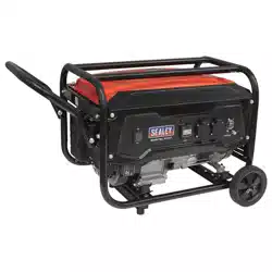
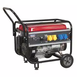
2. INTRODUCTION
Heavy-duty industrial frame design provides full protection and aids portability. Suitable for running power tools and lighting units etc.
Fitted with automatic voltage control which protects the unit and provides higher eciency and a long running time of up to 10 hours on
a full tank. Fitted with 12V battery charging outlet, 230V and 110V sockets. Powerful and reliable generator tted with maintenance-free
brushless alternator. Smooth running unit tted with anti-vibration mountings. Low oil cut-out feature and fuel gauge.
Refer to
instructions
Electrical shock
hazard
Hot surfaces
Wear ear
protection
Warning!
6000W 110/230V GENERATOR 13HP
MODEL NO: GG7500
Original Language Version
© Jack Sealey Limited
GG7500 Issue 5 (ALL) 05/09/23
3. SPECIFICATION
Model No: .......................................................... GG7500
Continuous Power Rating: ...................................5000W
Current Rating: .......................................... 22A/45A/8.3A
Displacement (cc): ....................................................389
Fuel Tank: .................................................................25L
IP Rating: ..............................................................IP23M
Maximum Power Rating: ......................................6000W
Maximum Running Time: .........................................10hr
Motor Power: ................................................9.7kW/13hp
Motor Type: .............................................4-Stroke Petrol
Noise Rating: .....................................................96dB(A)
Output: ............................. 230V/110V AC~50Hz/12V DC
4. OPERATION
WARNING! Before use, ensure you read, understand and comply with the safety instructions in this document. Ensure you fully
understand the application and limitations, as well as the potential hazards, of the generator.
WARNING! Never connect the generating set earth lead to pipes. Pipes may carry inflammable substances such as gas or domestic fuel
and there is a risk of fire or explosion in the event of a short circuit.
WARNING! Never run the engine without an air filter fitted.
4.1. EARTHING
The generating set must be earthed every time it is used, to reduce the chance of electric shock. To do this, use a 12mm² copper wire and
bolt it to the generator chassis using the earthing point seen in Fig.4. At the other end, bolt it to an earthing rod of copper or brass which
has been driven into the ground. This earthing connection will also dissipate static electricity generated by the electrical equipment.
4.2. PRE START-UP OF THE GENERATOR
WARNING! Check the engine oil level before each start-up. Only use an approved oil and NEVER operate the engine with insufficient oil.
9 Check the air filter element to ensure it is clean and in good condition, clean or replace as necessary.
4.3. FILLING WITH ENGINE OIL
4.3.1. Ensure the generator set is on a flat horizontal surface.
4.3.2. Unscrew the oil filler cap and wipe the dipstick clean.
4.3.3. Insert the dipstick into the filler neck but DO NOT screw in.
4.3.4. Remove the dipstick and check the level indicated. If the level is too low, top up to the top of the filler neck with the recommended oil.
4.3.5. Replace the dipstick and screw in the oil filler cap.
4.4. FILLING WITH FUEL
WARNING! NEVER refuel when the engine is running or when the engine is hot.
WARNING! Petrol is highly flammable and petrol vapour is explosive.
WARNING! Never use an oil/fuel mixture or any polluted fuel.
4.4.1. Ensure all electrical loads are DISCONNECTED and the circuit breaker where fitted is in the “OFF” position.
4.4.2. Ensure the area around the fuel tank filler hole is clean.
4.4.3. Remove the fuel tank filler cap, check the level of the fuel and refill with the recommended fuel if necessary.
8 DO NOT over-fill the fuel tank, always leave room for the fuel to expand.
4.5. STARTING THE GENERATOR
WARNING! The output sockets will be live once the engine has started.
WARNING! DO NOT run this generator unless there is adequate ventilation, the exhaust gases contain deadly carbon monoxide.
FIG.1
Choke Lever
FIG.2
FIG.3
4.5.1. Ensure you have performed all actions in paragraphs 4.2. and 4.3. above.
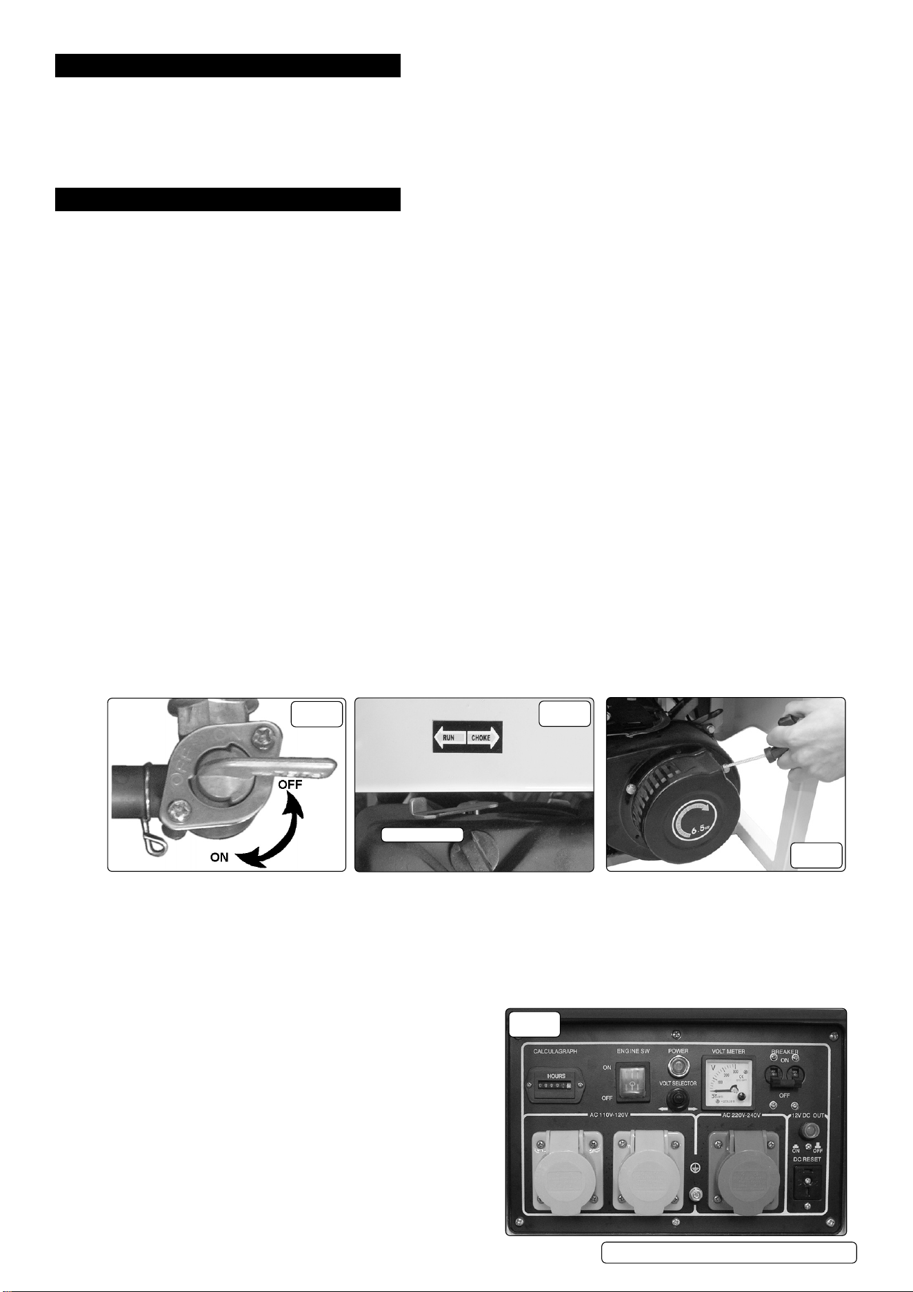
4.5.2. Turn the fuel valve to the “ON” position, Fig.1.
4.5.3. Move the choke lever to the CHOKE position, Fig.2.
Note: If starting a warm engine or when the ambient temperature is high, move the choke control to the “RUN” position.
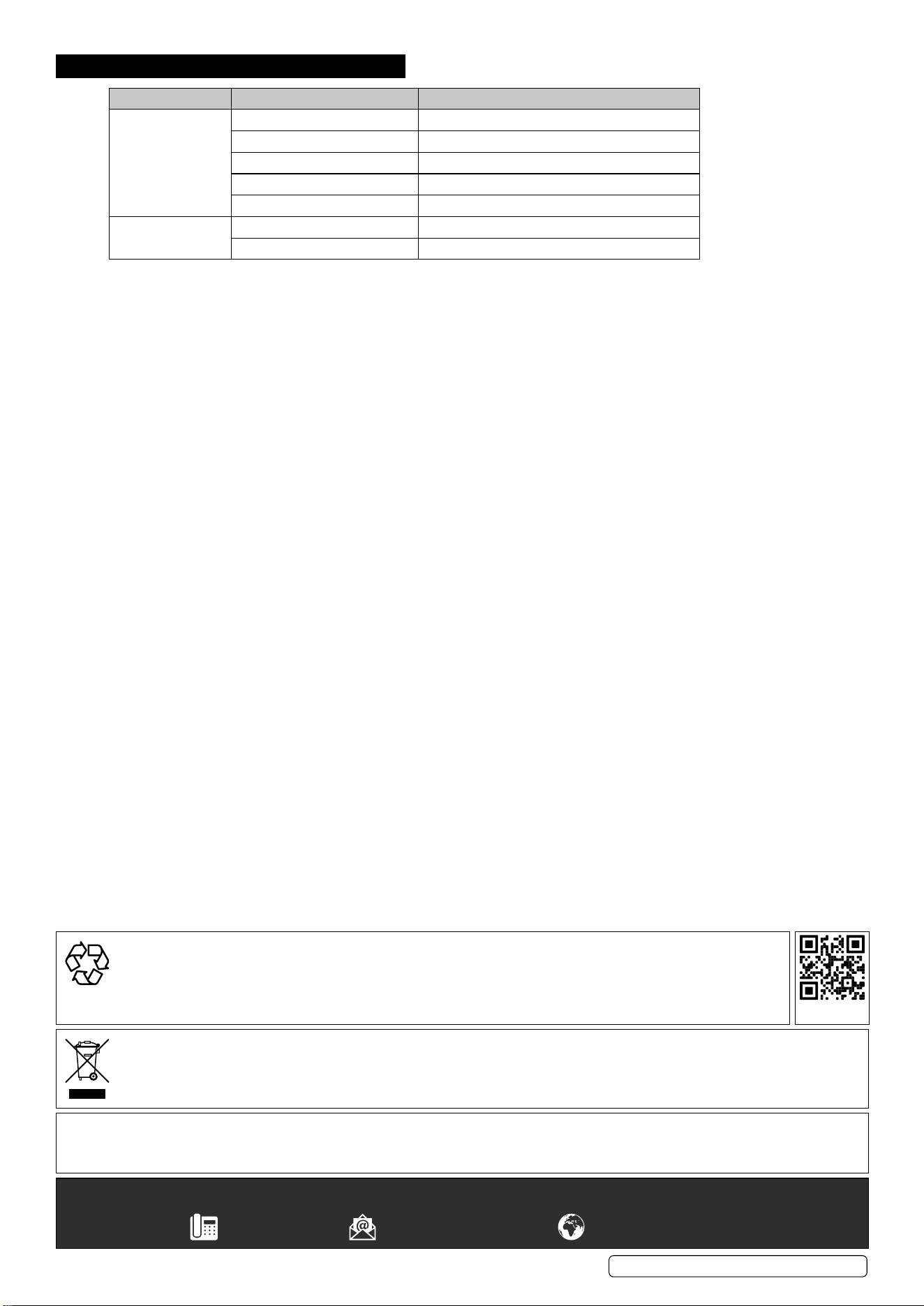
4.5.4. Set the Engine Switch to the “ON” position, Fig.4.
Note: Ensure there is sufficient free area around the generator to prevent personal injury when pulling the rope.
4.5.5. Grasp the recoil handle and pull rope slowly until some resistance is felt (Fig.3). Let rope rewind slowly, then pull with a rapid full arm
stroke. Let rope slowly return.
4.5.6. When engine starts, move choke lever to half choke position
until engine runs smoothly and then to the “RUN” position.
If engine fails to start, repeat the procedure from section 4.5. If
it still will not start, refer to ’Trouble-Shooting’ section. If
necessary contact your authorised Sealey service agent.
4.5.7. On models fitted with a circuit breaker, set the switch to “ON”.
WARNING! Never pull out the starting handle when the engine is
running, as this will damage the engine.
4.6. USING THE GENERATOR
WARNING! DO NOT exceed the wattage capacity of the
generator.
4.6.1. Allow the engine to warm up (approximately 3 minutes).
4.6.2. Connect the equipment to the appropriate generator socket.
WARNING! If connecting to a home power circuit, the unit must be
Original Language Version
© Jack Sealey Limited
GG7500 Issue 5 (ALL) 05/09/23
FIG.4
wired in by a qualified electrician. The incorrect installation of this unit may cause damage to the generator, the appliance and may lead to
the risk of fire and/or personal injury.
4.7. TO STOP THE GENERATOR (FIG.4)
4.7.1. Disconnect the electrical load.
4.7.2. Allow the engine to run unloaded for 1 - 2 mins.
4.7.3. Stop engine by moving the engine switch to the “OFF” position.
4.7.4. Set the circuit breaker to the “OFF” position.
4.7.5. Turn off the fuel valve, Fig.1.
5. STORAGE AND TRANSPORTATION
5.1. STORING THE GENERATOR
5.1.1. Always drain o the fuel from the carburettor and fuel tank when storing the generator for long periods of time.
5.1.2. Drain and rell the engine oil, see Section 6.1.
5.1.3. Store in a dry and childproof area.
5.2. TRANSPORTING THE GENERATOR
5.2.1. Turn the engine switch and the fuel tap to the “OFF” position, g.1.
5.2.2. Keep the generator level to avoid fuel spillage and away from sources of ignition.
5.2.3. Allow the generator to cool before transportation, the engine and exhaust system can cause serious burns.
6. MAINTENANCE
Float
Chamber
FIG.7
Foam
Element
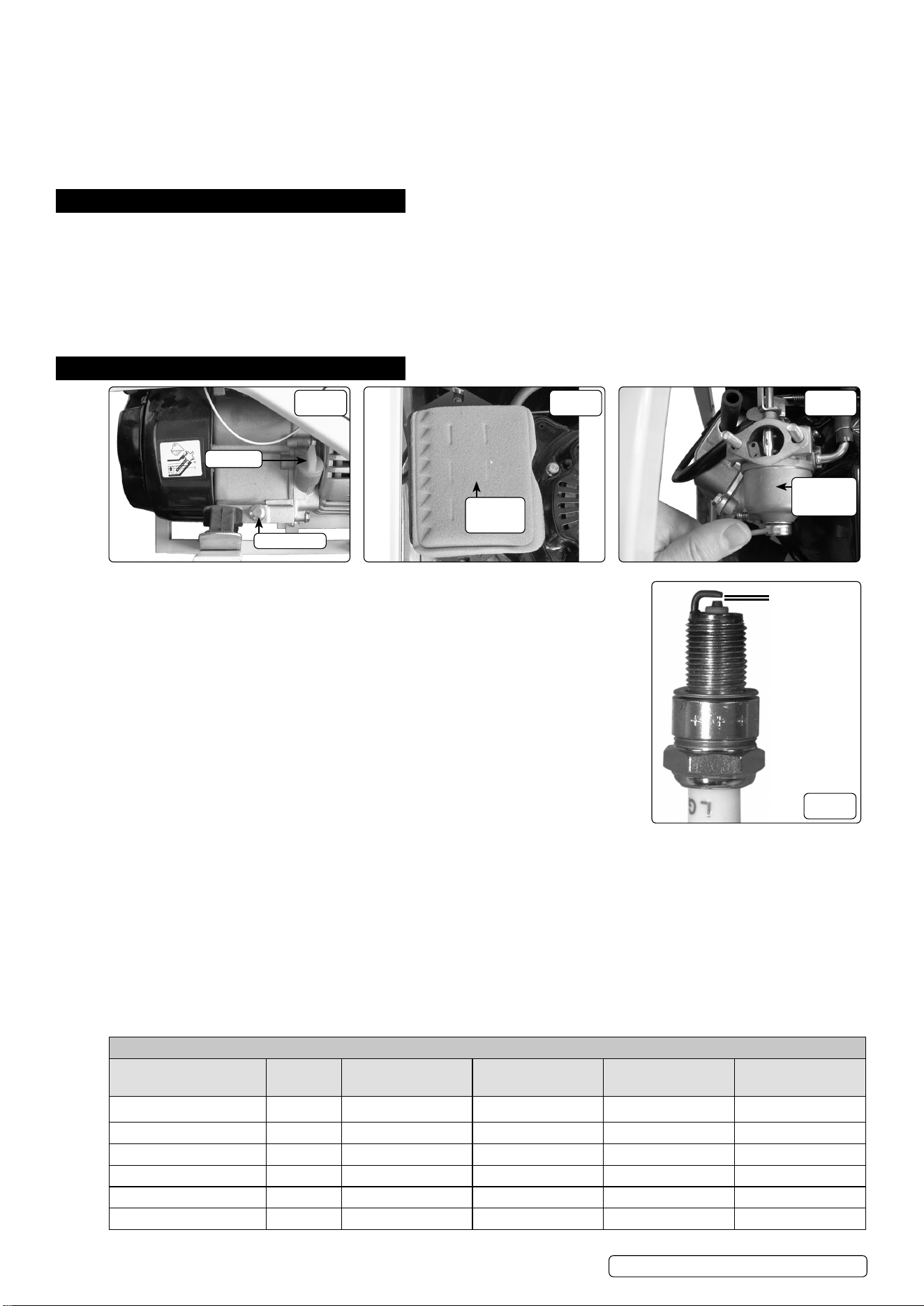
FIG.6
Dipstick
Drain Plug
FIG.5
Note: Maintenance should be carried out as stated in the maintenance schedule.
6.1. CHANGING THE OIL (FIG 5)
6.1.1. Unscrew the dipstick.
6.1.2. Place a suitable container underneath the drain plug and then remove the drain plug.
6.1.3. Once the oil has drained replace the drain plug.
6.1.4. Refill with SAE 10W/30 oil.
6.1.5. Replace dipstick.
6.2. AIR FILTER (FIG.6)
6.2.1. Remove clips and remove the air filter cover.
6.2.2. Remove the foam element from the air filter assembly.
6.2.3. Wash out the element using paraffin and dry thoroughly.
6.2.4. Dip the element into clean machine oil and remove excess oil.
6.2.5. Ensure air filter housing is clean and replace element and cover.
Note: Wear suitable protective gloves when handling element during cleaning and reproofing.
6.3. SPARK PLUG (FIG.8)
6.3.1. Remove the high tension lead from the spark plug.
6.3.2. Using the supplied spark plug wrench remove the spark plug.
6.3.3. Clean spark plug with a wire brush.
6.3.4. Check the electrode gap with a set of feeler gauges, the gap should be 0.7mm to 0.8mm (Fig.8).
6.3.5. Check the spark plug washer is in good condition and screw the plug in by hand to avoid cross threading.
6.3.6. Once the spark plug is installed, tighten it using the spark plug wrench to compress the washer.
Note: In the case of a new spark plug being fitted, screw it in by hand and tighten it by 1/2 turn with a spark plug wrench to compress the
washer. If the spark plug has already been used, screw it in by hand and only tighten it by 1/8 to 1/4 turn to compress the washer
6.4. CARBURETTOR FLOAT CHAMBER (FIG.7)
6.4.1. Turn off the fuel supply switch.
6.4.2. Using a 10mm spanner remove the bolt underneath the float chamber (Fig.7) and lower the chamber taking care not to spill any fuel in the
process. Dispose of old fuel in line with local authority regulations and thoroughly clean the chamber.
6.4.3. Replace the O-ring and refit the float chamber.
6.4.4. Turn on fuel supply and check for leaks.
MAINTENANCE SCHEDULE
Item Daily Check 20hrs or rst month
50hrs or every 3
months
100hrs or every 6
months 300hrs or yearly
Check Engine Oil Check
Replace Engine Oil Replace Replace
Check Air Filter Check
Clean Air Filter Clean
Spark Plug Clean Replace
Carburettor Float Chamber Clean
FIG.8
0.7 to 0.8mm
Original Language Version
© Jack Sealey Limited
GG7500 Issue 5 (ALL) 05/09/23
7. TROUBLESHOOTING
PROBLEM CAUSE REMEDY
Engine will not start Insucient fuel Check and rell fuel tank
Engine switch in "OFF" position Switch to "ON"
Engine oil is low Check and top up oil
Spark plug fouled Clean or replace spark plug
Incorrect starting technique Read ‘operation’ for correct technique
No power generated Circuit breaker in OFF position Reset to ON
Incorrect voltage selected Set switch to correct voltage (excluding GG1100)
WEEE REGULATIONS
Dispose of this product at the end of its working life in compliance with the EU Directive on Waste Electrical and Electronic Equipment
(WEEE). When the product is no longer required, it must be disposed of in an environmentally protective way. Contact your local solid
waste authority for recycling information.
Original Language Version
© Jack Sealey Limited
GG7500 Issue 5 (ALL) 05/09/23
Sealey Group, Kempson Way, Suffolk Business Park, Bury St Edmunds, Suffolk. IP32 7AR
01284 757500 sales@sealey.co.uk www.sealey.co.uk
Note: It is our policy to continually improve products and as such we reserve the right to alter data, specications and component parts without prior notice.
Important: No Liability is accepted for incorrect use of this product.
Warranty: Guarantee is 12 months from purchase date, proof of which is required for any claim.
ENVIRONMENT PROTECTION
Recycle unwanted materials instead of disposing of them as waste. All tools, accessories and packaging should be
sorted, taken to a recycling centre and disposed of in a manner which is compatible with the environment. When
the product becomes completely unserviceable and requires disposal, drain any uids (if applicable) into approved
containers and dispose of the product and uids according to local regulations.
REGISTER YOUR
PURCHASE HERE