Loading ...
Loading ...
Loading ...
Page 24mrcool.com
Outdoor Unit Installation
BEFORE PERFORMING ELECTRICAL
WORK, READ THESE REGULATIONS
1. All wiring must comply with local and
national electrical codes, and must be installed
by a licensed electrician.
2. All electrical connections must be made
according to the Electrical Connection
Diagram located on the panels of the indoor
and outdoor units.
3. If there is a serious safety issue with the
power supply, stop work immediately. Explain
your reasoning to the client, and refuse to
install the unit until the safety issue is properly
resolved.
4. Power voltage should be within 90-100% of
5. Circuit, including any switches, should have
a capacity 1.5 times the maximum unit current
(amps).
6.
approved circuit breaker or switch that discon-
nects all poles and has has a contact separa-
tion of at least 1/8in (3mm).
7. DO NOT connect another appliance to the
same circuit.
8. Make sure to properly ground the air
conditioner.
9.
Loose wiring can cause the terminal to over-
10. DO NOT let wires touch or rest against
refrigerant tubing, the compressor, or any
moving parts within the unit.
11. If the unit has an auxiliary electric heater, it
must be installed at least 40 in (1 meter) away
from combustible materials.
Step 4: Connect signal and power cables
To reduce vibration of wall-mounted unit
If allowed, you can install the wall-mounted unit
with rubber gaskets to reduce vibration and noise.
wall-mounted installation continued
6. Check that the mounting brackets are level.
7. Carefully lift unit and place its mounting feet on
the brackets.
8.
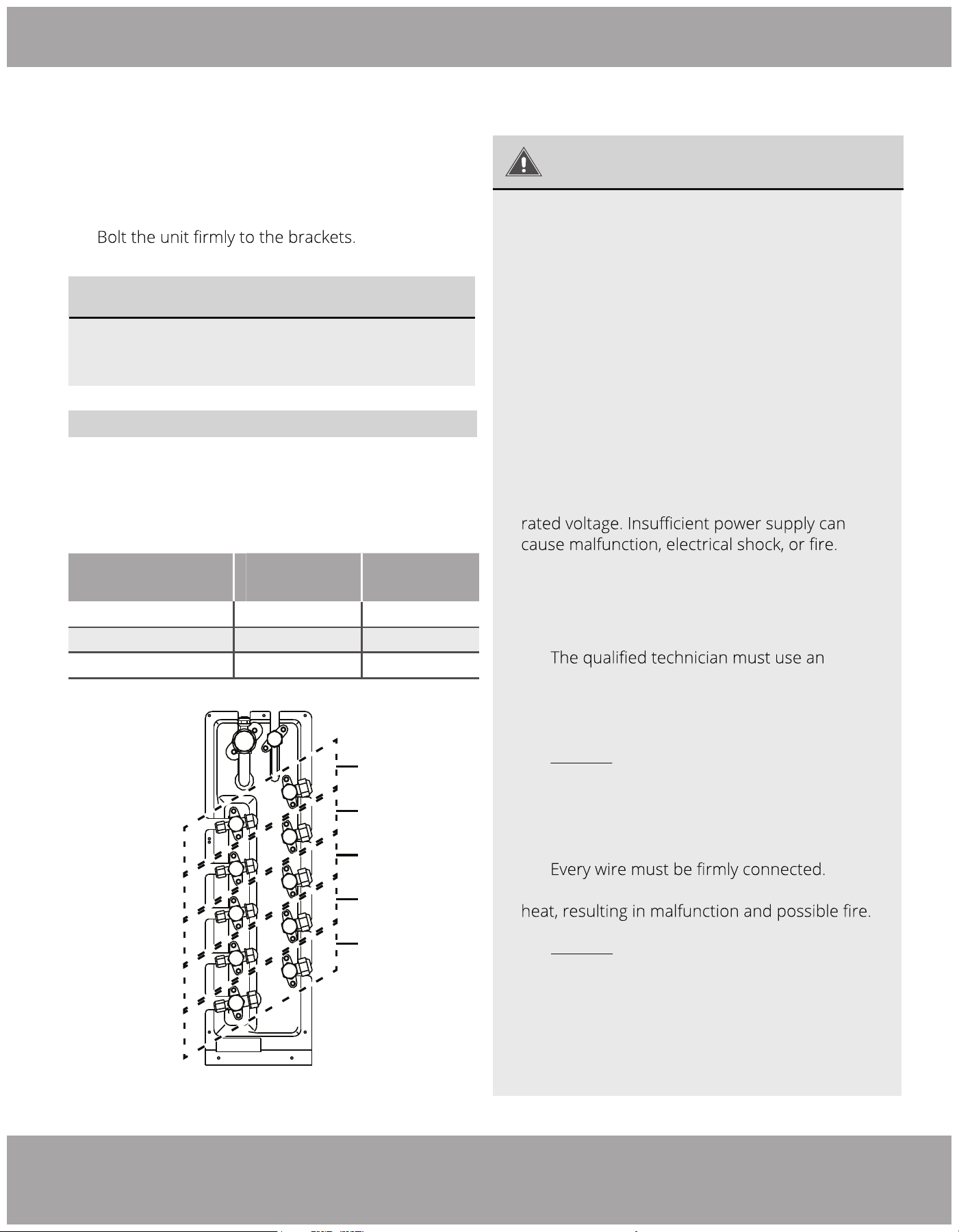
When Selecting a 24K Indoor Unit
The 24K indoor unit can only be connected with A system,
if there are two 24K indoor units, they can be connected
with A and B system. (See Fig. 5.8)
Indoor Unit Capacity
(Btu/h)
Liquid
Gas
9K/12K 1/4 in (6.4 mm)
1/4 in (6.4 mm)
3/8 in (9.5 mm)
12K/18K
24K
3/8 in (9.5 mm)
1/2 in (12.7 mm)
5/8 in (15.9 mm)
Table 5.2: Connective pipe size of A and B system
Fig. 4.10
A System
D System
C System
B System
E System
Loading ...
Loading ...
Loading ...