
Appearance
1
ON
OF F
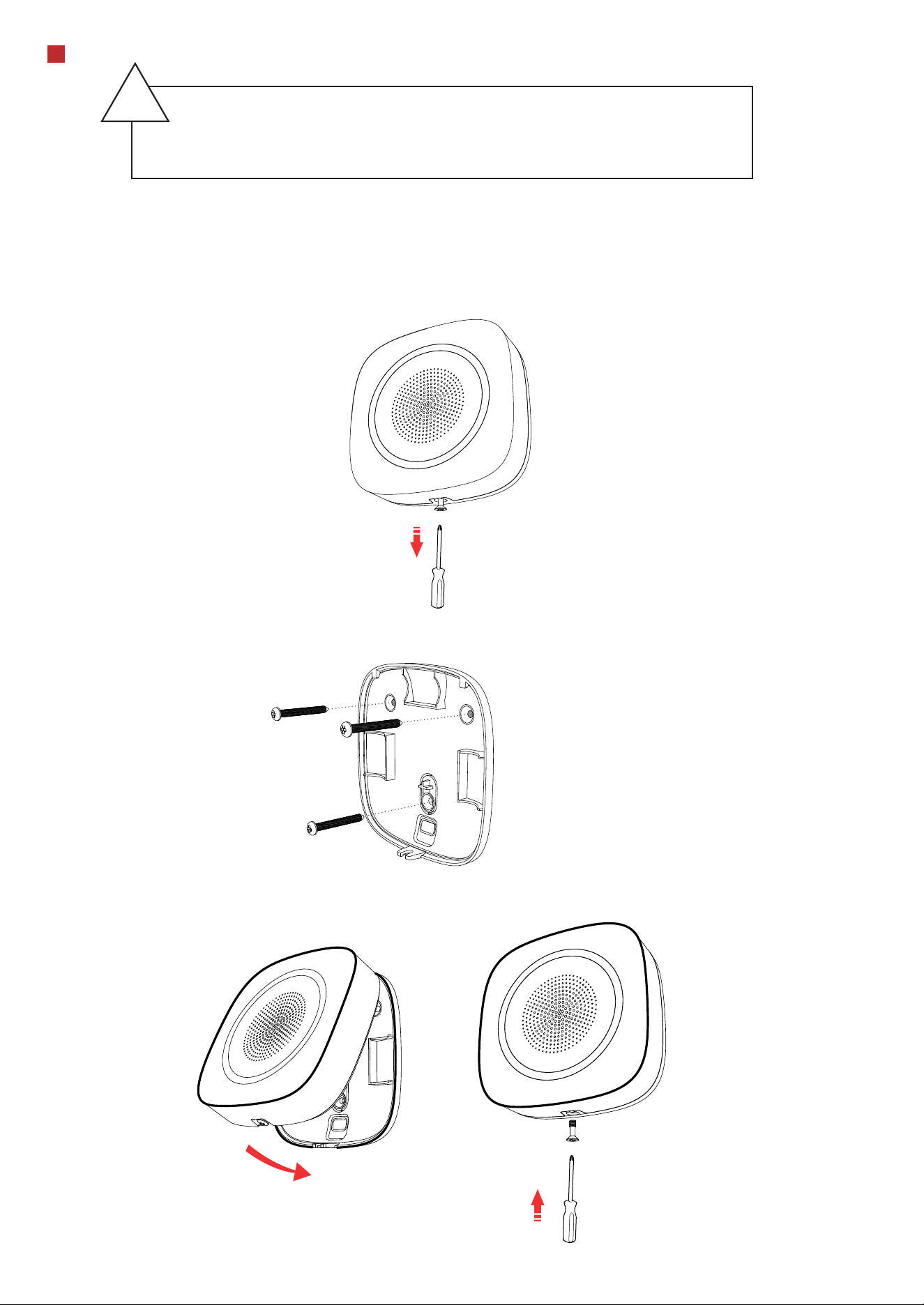
Indicator Buzzer Cable Hole Set Screw Tamper
Screw Hole
Tamper Button Power Switch
2
Indication
LED Indication Description
Buzzer
Armed
Operations
Green LED ashes 7 times.
Enrolled
Red LED ashes 3 times.
Formatted
Red LED ashes twice.
Disarmed
Res LED ashes once.
Display Signal Strength
indicator turns red for 3 s.
indicator ashes red for 3 s.
Disconnected
Week Signal
indicator turns orange for 3 s
Medium Signal
indicator turns green for 3 s.
Strong Signal
Check signal strength and select installation place
Enter the signal checking mode by operating on the AX PRO.
Zone Alarm
Note: You can sign in web client “Device - Sounder - Settings” or
the mobile client “wireless Device” to adjust the volume of
buzzer.
Two beeps.
Disarmed
One beep.Armed
Fire bell.Fire Alarm
High and low frequemcy alternated
impulsive sound.
Panic Alarm
Rapid high frequency impulsive sound.
DS-PS1-I-WE
Wireless Indoor Sounder
Diagram References
E N G L I S H
©2023 Hangzhou Hikvision Digital Technology Co., Ltd. All rights reserved.
About this Manual
The Manual includes instructions for using and managing the Product. Pictures, charts, images and all other information hereinafter are for description and explanation only. The information contained in the Manual is subject to change,
without notice, due to firmware updates or other reasons. Please find the latest version of this Manual at the Hikvision website (https://www.hikvision.com/).
Please use this Manual with the guidance and assistance of professionals trained in supporting the Product.
Trademarks
and other Hikvision’s trademarks and logos are the properties of Hikvision in various jurisdictions.
Other trademarks and logos mentioned are the properties of their respective owners.
Disclaimer
TO THE MAXIMUM EXTENT PERMITTED BY APPLICABLE LAW, THIS MANUAL AND THE PRODUCT DESCRIBED, WITH ITS HARDWARE, SOFTWARE AND FIRMWARE, ARE PROVIDED “AS IS” AND “WITH ALL FAULTS AND ERRORS”. HIKVISION MAKES
NO WARRANTIES, EXPRESS OR IMPLIED, INCLUDING WITHOUT LIMITATION, MERCHANTABILITY, SATISFACTORY QUALITY, OR FITNESS FOR A PARTICULAR PURPOSE. THE USE OF THE PRODUCT BY YOU IS AT YOUR OWN RISK. IN NO EVENT WILL
HIKVISION BE LIABLE TO YOU FOR ANY SPECIAL, CONSEQUENTIAL, INCIDENTAL, OR INDIRECT DAMAGES, INCLUDING, AMONG OTHERS, DAMAGES FOR LOSS OF BUSINESS PROFITS, BUSINESS INTERRUPTION, OR LOSS OF DATA, CORRUPTION OF
SYSTEMS, OR LOSS OF DOCUMENTATION, WHETHER BASED ON BREACH OF CONTRACT, TORT (INCLUDING NEGLIGENCE), PRODUCT LIABILITY, OR OTHERWISE, IN CONNECTION WITH THE USE OF THE PRODUCT, EVEN IF HIKVISION HAS BEEN
ADVISED OF THE POSSIBILITY OF SUCH DAMAGES OR LOSS.
YOU ACKNOWLEDGE THAT THE NATURE OF THE INTERNET PROVIDES FOR INHERENT SECURITY RISKS, AND HIKVISION SHALL NOT TAKE ANY RESPONSIBILITIES FOR ABNORMAL OPERATION, PRIVACY LEAKAGE OR OTHER DAMAGES RESULTING
FROM CYBER-ATTACK, HACKER ATTACK, VIRUS INFECTION, OR OTHER INTERNET SECURITY RISKS; HOWEVER, HIKVISION WILL PROVIDE TIMELY TECHNICAL SUPPORT IF REQUIRED.
YOU AGREE TO USE THIS PRODUCT IN COMPLIANCE WITH ALL APPLICABLE LAWS, AND YOU ARE SOLELY RESPONSIBLE FOR ENSURING THAT YOUR USE CONFORMS TO THE APPLICABLE LAW. ESPECIALLY, YOU ARE RESPONSIBLE, FOR USING THIS
PRODUCT IN A MANNER THAT DOES NOT INFRINGE ON THE RIGHTS OF THIRD PARTIES, INCLUDING WITHOUT LIMITATION, RIGHTS OF PUBLICITY, INTELLECTUAL PROPERTY RIGHTS, OR DATA PROTECTION AND OTHER PRIVACY RIGHTS. YOU
SHALL NOT USE THIS PRODUCT FOR ANY PROHIBITED END-USES, INCLUDING THE DEVELOPMENT OR PRODUCTION OF WEAPONS OF MASS DESTRUCTION, THE DEVELOPMENT OR PRODUCTION OF CHEMICAL OR BIOLOGICAL WEAPONS, ANY
ACTIVITIES IN THE CONTEXT RELATED TO ANY NUCLEAR EXPLOSIVE OR UNSAFE NUCLEAR FUEL-CYCLE, OR IN SUPPORT OF HUMAN RIGHTS ABUSES.
IN THE EVENT OF ANY CONFLICTS BETWEEN THIS MANUAL AND THE APPLICABLE LAW, THE LATTER PREVAILS.
1
4
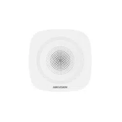
Enrollment
1. Remove the screw on the bottom of the sounder, and disassemble the peripheral and remove the rear panel..
2. Insert the batteries.
Note: for re-enrollment, you need to hold the tamper button while powering the peripheral on simultaneously.
2
CAUTION
RISK OF EXPLOSION IF BATTERY IS
REPLACED BY AN INCORRECT TYPE.
DISPOSE OF USED BATTERIES
ACCORDING TO THE INSTRUCTIONS
CHEMICAL BURNING DANGER
DO NOT SWALLOW THE BATTERY
KEEP NEW AND USED BATTERIES
AWAY FROM THE CHILDREN
ON
OF F
ON
OF F
Enroll the Peripheral Locally
Enroll the Peripheral with APP
1. In the APP, tap the "Enrollment Mode" button on the control panel page to make the control panel enter the enroll-
ment status.
2. Push the power switch of the peripheral to on, and it will be automatically enrolled to the control panel.
1. In the APP, tap the icon "+"and scan the QR code on the peripheral or enter the serial No. (Last 5 digit) of the peripheral.
2. Push the power switch of the peripheral to on, and it will be automatically enrolled to the control panel.
3. Log in to the APP Store, download and install App.
4. Power on the security control panel.
5. Log in the APP and tap the icon "+" . Scan the QR code or input the control panel serial No. (Last 5 digit) to add the
control panel.
6. Enroll the peripheral locally, with OR code, or with serial No..
INSTALL THE BATTERIES ACCORDING
TO THE POLARITY MARK ON THE
BATTERY HOLDER. THE OPPOSITE
POLARITY MAY CAUSE DEVICE
DAMAGE
5
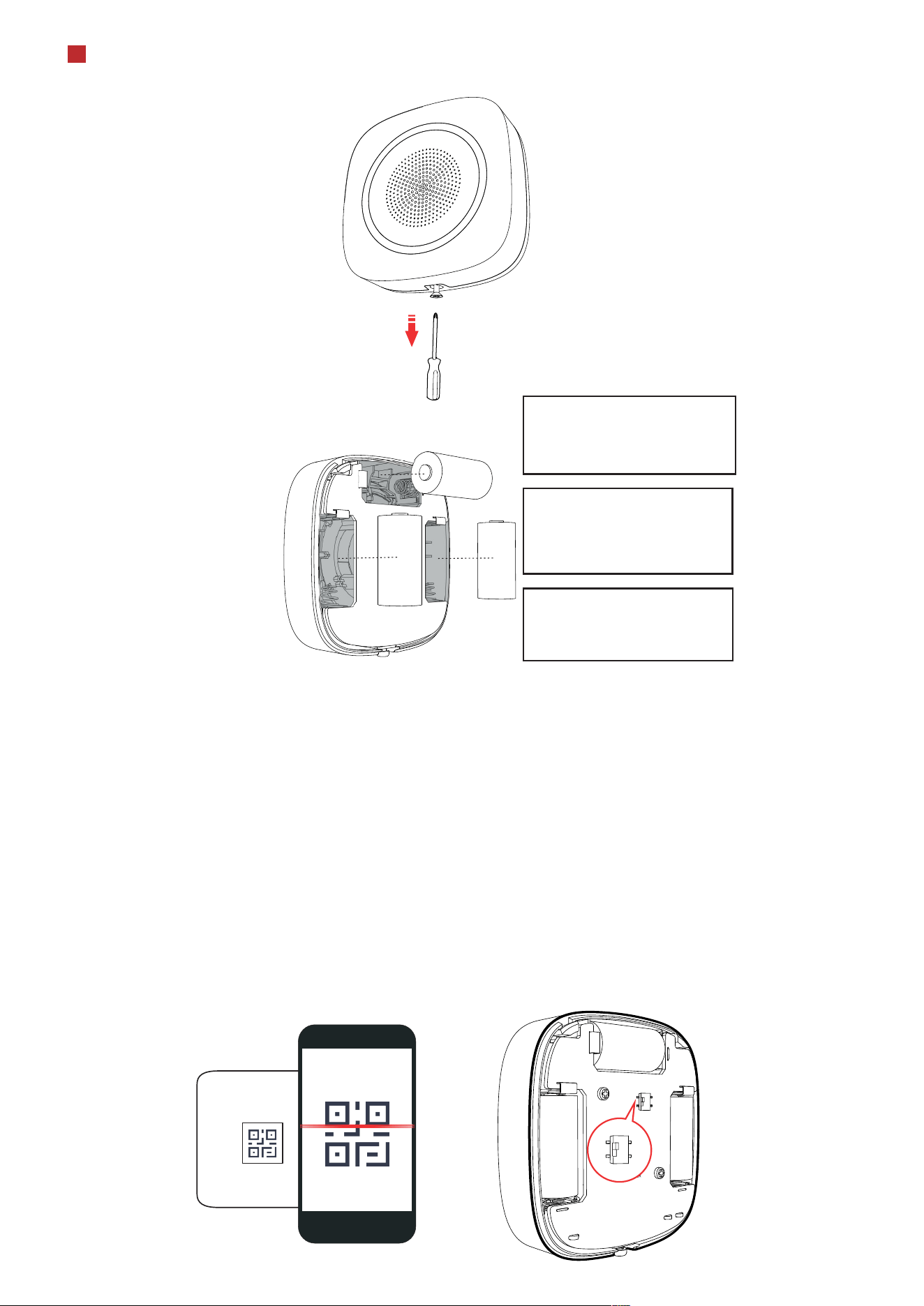
Installation
2.Loosen the set screw at the bottom of the sounder and remove the front panel.
3.Secure the sounder with other three screws.
4.Fix the front panel on the sounder body. Tighten the set screw to complete the installation.
-The additional force shall be equal to three times the weight of the equipment but not
less than 50N. The equipment and its associated mounting means shall remain secure
during the installation. After the installation, the equipment, including any associated
mounting plate, shall not be damaged.
-Install the device on the place with nonammable surface, such as concrete wall.
!
3
1. Check signal strength and select tinstallation place
Enter the signal checking mode by operating on the control panel.
Signal indicator turns green for 3 s: Strong.
Signal indicator turns orange for 3 s: Medium.
Signal indicator turns red for 3 s: Weak.
Signal indicator ashes red for 3 s: Lost.
7
Operation
8
Operation Caution and Device Maintenance
Specication
6
Formating
Hold the tamper button, and push the power switch to ON simultaneously. Release the tamper button after 8 s, and the
device will strats formating. While the formating is completed, the red LED ashes 3 times.
- All the electronic operation should be strictly compliance with the electrical safety regulations, re prevention regula-
tions and other related regulations in your local region.
- Do not drop the device or subject it to physical shock, and do not expose it to high electromagnetism radiation. Avoid
the equipment installation on vibrations surface or places subject to shock (ignorance can cause equipment damage).
- Please make sure that the power has been disconnected before you wire, install or dismantle the device.
- If smoke, odors or noise rise from the device, turn o the power at once and unplug the power cable, and then please
contact the service center.
- Do not drop the device or subject it to physical shock, and do not expose it to high electromagnetism radiation. Avoid
the equipment installation on vibrations surface or places subject to shock (ignorance can cause equipment damage).
- Do not place the device in extremely hot (refer to the specication of the device for the detailed operation tempera-
ture), cold, dusty or damp locations, and do not expose it to high electromagnetic radiation.
- The device for indoor use shall be kept from rain and moisture.
Exposing the equipment to direct sun light, low ventilation or heat source such as heater or radiator is forbidden (igno-
rance can cause re danger).
- Do not aim the device at the sun or extra bright places. A blooming or smear may occur otherwise (which is not a
malfunction however), and aecting the endurance of sensor at the same time.
- Improper use or replacement of the battery may result in hazard of explosion. Replace with the same or equivalent type
only. Dispose of used batteries according to the instructions provided by the battery manufacturer.
- Do not expose the device to the corrosive gas. Otherwise the equipment damage may occur.
- Do not expose the device to the explosive situation.
4
ON
OF F
Frequency 868 MHz
Metod Two-way communication
Distance 1.6 km
Indicator Red/Green
Strobe light Red/Blue
Power Battery (default power supply method)
Consumption Static consumption: 30 to 40uA
Battery life span
3 CR123A, 3 years in work status (triggered every two
weeks and alerting 90 s for each triggering)
Power switch Power switch
Tamper switch Front and rear tamper-proof
Buzzer Decibel 90 to 110 db
Operation Temperature
-10
°C to 55°C
Operation Humidity 10% to 90%
Installation Wall mounting
Power
General
RF
Interface
Indication