
11-FUNCTION PROFESSIONAL AUTO-RANGING
DIGITAL MULTIMETER
MODEL NO: TM103
Thank you for purchasing a Sealey product. Manufactured to a high standard, this product will, if used according to these instructions,
and properly maintained, give you years of trouble free performance.
IMPORTANT: PLEASE READ THESE INSTRUCTIONS CAREFULLY. NOTE THE SAFE OPERATIONAL REQUIREMENTS, WARNINGS & CAUTIONS. USE
THE PRODUCT CORRECTLY AND WITH CARE FOR THE PURPOSE FOR WHICH IT IS INTENDED. FAILURE TO DO SO MAY CAUSE DAMAGE AND/OR
PERSONAL INJURY AND WILL INVALIDATE THE WARRANTY. KEEP THESE INSTRUCTIONS SAFE FOR FUTURE USE.
1. SAFETY
1.1. PERSONAL PRECAUTIONS
9 When using this multimeter, please observe all normal safety rules concerning:
Protection against the dangers of electrical current.
Protection of the meter against misuse.
9 Full compliance with safety standards can only be guaranteed if used with the test leads supplied. If necessary, they must be replaced
with genuine Sealey leads with the same electrical ratings. Failure to do so will invalidate the warranty.
8 DO NOT use leads if damaged or if the wires are bared in any way.
1.2. GENERAL SAFETY INSTRUCTIONS
9 Familiarise yourself with the application and limitations of the multimeter as well as the potential hazards.
IF IN ANY DOUBT CONSULT A QUALIFIED ELECTRICIAN.
WARNING! USE EXTREME CAUTION WHEN WORKING WITH HIGH VOLTAGES.
9 When the meter is connected to a circuit, do not touch unused meter terminals.
9 When the magnitude of the value to be measured is unknown, set the range selector to the highest value available.
9 Before commencing testing, follow instructions below and select the correct input sockets, function and range on the multimeter.
9 Before rotating the rotary switch to change functions, disconnect the test leads from the circuit under test.
9 Take care when working with voltages above 35V DC or 25V AC rms. These voltages are considered a shock hazard.
9 Keep fingers behind the probe barriers whilst measuring.
8 DO NOT test voltages above 600V - the circuitry of the multimeter may be destroyed.
WARNING! NEVER connect the multimeter to a voltage source / live circuit when the rotary switch is set to any other function apart from
Voltage testing.
WARNING! NEVER perform resistance, transistor, diode or continuity measurements on live circuits.
9 ALWAYS discharge lter capacitors in power supplies and disconnect the power when making resistance or diode tests.
WARNING! Voltage checks on electrical outlets can be difcult and misleading because of the uncertainty of connection to the
recessed electrical contacts. Other means should be used to ensure that the terminals are not “live”.
8 DO NOT use the multimeter in a potentially explosive atmosphere.
8 DO NOT operate the meter unless the back cover and the battery and fuse doors are in place and fastened securely.
9 If any abnormal readings are observed, the multimeter must be checked out by an authorised technician.
9 When not in use, store the multimeter carefully in a safe, dry, childproof location out of direct sunlight. Storage temperature range is
-20°C to 60°C.
9 ALWAYS turn off the power and disconnect the test leads before opening the doors to replace the fuse or batteries.
9 The user shall ensure that test probes are correctly selected in order to prevent danger. Probes shall be selected to ensure that adequate
barriers guard against inadvertent hand contact with live conductors under test and that probes have minimal exposed probe tips. Where
there is a risk of the probe tip short circuiting with other live conductors under test, it is recommended that the exposed tip length shall not
exceed 4mm.
NOTE: The warnings, cautions and instructions referred to in this manual cannot cover all possible conditions and situations that may occur.
It must be understood that common sense and caution are factors which cannot be built into this product, but must be applied by the operator.
1.3. SAFETY SYMBOLS
This symbol adjacent to another symbol, terminal or operating device indicates that the operator must refer
to an explanation in the Operating Instructions to avoid personal injury or damage to the meter.
WARNING
This WARNING symbol indicates a potentially hazardous situation, which if not avoided, could result in
death or serious injury.
CAUTION
This CAUTION symbol indicates a potentially hazardous situation, which if not avoided, may result damage
to the product.
This symbol, adjacent to one or more terminals identies them as being associated with ranges that may,
in normal use, be subjected to particularly hazardous voltages. For maximum safety, the meter and its test
leads should not be handled when these terminals are energized.
This symbol indicates that a device is protected throughout by double insulation or reinforced insulation.
Refer to
instructions
Electrical shock
hazard
TM103 Issue 4 (3) 05/04/24
Original Language Version
© Jack Sealey Limited
WARNING! NEVER apply voltage or current to the meter that exceeds the specied maximum as shown below:
INPUT LIMITS
Function Maximum Input
V DC or V AC 600V DC/AC
mA DC/AC 400mA DC/AC
A DC/AC 10A DC/AC
Frequency, Resistance, Capacitance,
Duty cycle,Diode test, Continuity
250V DC/AC
Temperature 250V DC/AC
WARNING! USE EXTREME CAUTION when working with high voltages.
1.4. BATTERY INSTALLATION
WARNING! To avoid electric shock, disconnect the test leads from any source of voltage before
removing the battery cover.
Disconnect the test leads from the meter.
Open the battery cover by loosening the two cover screws using a Phillips head screwdriver.
Insert the battery into battery holder, observing the correct polarity.
Replace the battery cover. Secure with the screws.
To remove battery reverse order of above.
WARNING! To avoid electric shock, do not operate the meter until the battery cover is in place and
fastened securely.
NOTE: If your meter does not work properly, check the fuses and battery to make sure that they are still
good and that they are properly inserted
2. INTRODUCTION
High precision auto-ranging multimeter. Conforms to EN 61010-1 CATIII 600V safety requirements for electrical equipment for
measurement, control and laboratory use. Features temperature measurement capability, max./data-hold, and auto-power-off function.
Double moulded housing with soft grip case and large display for ease of use. Practical probe and lead storage and integral upright stand
for use on the workbench. Supplied in zipped pouch with carry strap.
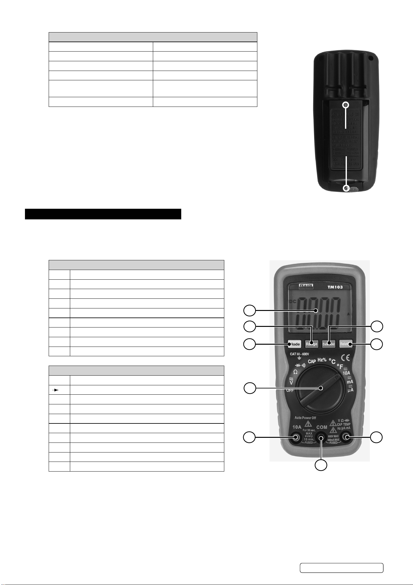
OVERVIEW
1 4000 Count Liquid Crystal Display With Symbolic Signs
2 Function Switch
3 10A (Positive) Input Jack For 10A DC or AC Measurements
4 Com (Negative) Input Jack
5 Positive Input Jack
6 Mode Push Button
7 Range Push Button
8 Data Hold Push Button
9 Relative Push Button
SYMBOLS AND ANNUNCIATORS
•))) Continuity
Diode Test
Μ Micro (amps)
M Milli ( volts, amps)
K Kilo (ohms)
Ω Ohms
VDC Volts Direct Current
VAC Volts Alternating Current
ADC Amps Direct Current
BAT Low Battery
REMOVE SCREWS
TO ACCESS
BATTERY AND
FUSES
1
7
6
2
3
4
5
9
8
TM103 Issue 4 (3) 05/04/24
Original Language Version
© Jack Sealey Limited
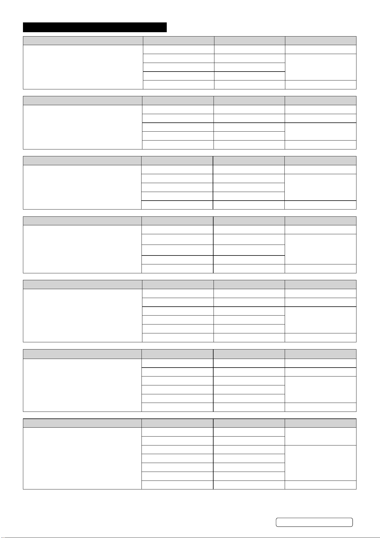
3. SPECIFICATION
FUNCTION RANGE RESOLUTION ACCURACY
DC Voltage: (Auto Ranging)
Input Impedance: 7.8MΩ
Maximum Input:600V dc or 600V ac rms.
400.0mV 0.1mV ±0.5% reading±2 digits
4.000V 1mV
±1.2% reading±2 digits40.00V 10mV
400.0V 100mV
600V 1V ±1.5% reading ± 2 digits
FUNCTION RANGE RESOLUTION ACCURACY
AC Voltage: (Auto-ranging ecept 400mV)
Input Impedance:7.8MΩ
Frequency Range:50 to 400Hz
Maximum Input:600V dc or 600V ac rms
400.0mV 0.1mV ±1.5% reading±15 digits
4.000V 1mV ±1.2% reading±3 digits
40.00V 10mV
±1.5% reading±3 digits
400.0V 100mV
600V 1V ±2.0% reading±4 digits
FUNCTION RANGE RESOLUTION ACCURACY
DC Current:(Auto-ranging for uA/mA)
Overload Protection:0.5A/250V and 10A/250V
Fuse
Maximum Input:400mA dc or 400mA ac rms on
uA/mA ranges, 10A dc or ac rms on 10A range
400.0µA 0.1µA ±1.0% reading±3 digits
4000µA 1µA
±1.5% reading±3 digits
40.00mA
10µA
400.0mA 100µA
10A 10mA ±2.5% reading±5 digits
FUNCTION RANGE RESOLUTION ACCURACY
AC Current:(Auto-ranging for uA/mA)
Overload Protection:0.5A/250V and 10A/250V
Fuse
Frequency Range: 50 to 400Hz
Maximum Input: 400mA dc or 400mA ac rms on
uA/mA ranges, 10A dc or ac rms on 10A range.
400.0µA 0.1µA ±1.5% reading±5 digits
4000µA 1µA
±1.8% reading±5 digits
40.00mA
10µA
400.0mA 100µA
10A 10mA ±3.0% reading± 7 digits
FUNCTION RANGE RESOLUTION ACCURACY
Resistance (Auto-Ranging)
Input Protection: 250V dc or 250V ac rms
400.0Ω 0.1Ω ±1.2% reading± 4 digits
4.000KΩ 1Ω ±1.0% reading± 2 digits
40.00KΩ 10Ω
±1.2% reading± 2 digits400.0KΩ 100Ω
4.000MΩ 1KΩ
40.00MΩ 10KΩ ±2.0% reading± 3 digits
FUNCTION RANGE RESOLUTION ACCURACY
Capacitance (Auto-Ranging)
Input Protection: 250V dc or 250V ac rms
4.000nF 1pF ±5.0% reading± 5 digits
40.00nF 10pF ±5.0% reading± 7 digits
400.0nF 0.1nF
±3.0% reading± 5 digits4.000µF 1nF
40.00µF 10nF
100.0µF 0.1µF ±5.0% reading± 5 digits
FUNCTION RANGE RESOLUTION ACCURACY
Frequency (Auto-ranging)
Sensitivity:>0.5V RMS while ≤1MHz
Sensitivity:>3V RMS while>1MHz
Overload protection:250V dc or ac rms
9.999Hz 0.001Hz
±1.5% reading± 5 digits
99.99Hz 0.01Hz
999.9Hz 0.1Hz
±1.2% reading± 3 digits
9.999KHz 1Hz
99.99KHz 10Hz
999.9KHz 100Hz
9.999MHz 1KHz ±1.5% reading± 4 digits
TM103 Issue 4 (3) 05/04/24
Original Language Version
© Jack Sealey Limited
FUNCTION RANGE RESOLUTION ACCURACY
Duty Cycle
Pulse width:>100us, <100ms
Frequency width:5Hz-150Hz
Sensitivity:>0.5V RMS
Overload protection:250V dc or ac rms
0.1%~99.9% 0.1% ±1.2% reading± 2 digits
FUNCTION RANGE RESOLUTION ACCURACY
Temperature
Sensor: Type K Thermocouple
Overload protection: 250V dc or ac rms
-20°C~+760°C 1°C
±3% reading ±5°C/9°F
-4°F~+1400°F 1°F
FUNCTION TEST CURRENT RESOLUTION ACCURACY
Diode Test
Open cuircuit voltage: 1.5V dc typical
Overload protection: 250V dc or ac rms
0.3mA typical 1mV ±10%reading±5 digits
AC Voltage (Accuracy): 400mV (±1.5%), 4V (±1.2%), 40V, 400V (±1.5%), 600V (±2%)
DC Voltage (Accuracy): 0-400mV (±0.5%), 4V, 40V, 400V (±1.2%), 600V (±1.5%)
AC Current (Accuracy): 400µA (±1.5%), 4000µA, 40mA, 400mA (±1.8%), 10A (±3%)
DC Current (Accuracy): 400µa (±1%), 4000µa, 40mA, 400mA (±1.5%), 10A (±2.5%)
Resistance (Accuracy): 0-400Ω (±1.2%), 4kΩ (±1%), 40kΩ, 400kΩ, 4MΩ (±1.2%), 40MΩ (±2%)
Capacitance (Accuracy): 4nF, 40nF (±5%), 400nF, 4µF, 40µF (±3%), 100µF (±5%)
Temperature (Accuracy): -20ºC to 760ºC (±3%), -4 to 1400ºF (±5%)
Frequency (Accuracy): 9.999Hz to 9.999MHz
Duty Cycle: 0.1%-99.9% (±1.2%)
Continuity Audible Yes
Diode Test: Yes
Transistor Test: No
Hi-Impact Rubber Case: Yes
Digits x Height: 2.1 x 24.5mm
Low Battery Indicator: Yes
Battery (Supplied): 1 x 9V
Information: Data-Hold & Auto-Power-Off
Size (L x W x D): 150 x 70 x 48mm
Weight: 255g
Conformity: EN 61010-1
4. OPERATION
WARNING! Risk of electrocution. High-voltage circuits, both AC and DC, are very dangerous and should be measured with great care.
ALWAYS turn the function switch to the “OFF” position when the meter is not in use.
If “OL” appears in the display during a measurement, the value exceeds the range you have selected. Change to a higher range.
NOTE: On some low AC and DC voltage ranges, with the test leads not connected to a device, the display may show a random
reading. This is normal and is caused by the high-input sensitivity. The reading will stabilise and give a proper measurement when
connected to a circuit.
4.1. MODE BUTTON
4.1.1. To select Diode / Continuity, DC / AC Hz / %Duty.
4.2. RANGE BUTTON
When the meter is rst turned on, it automatically goes into Auto Ranging. This automatically selects the best range for the
measurements being made and is generally the best mode for most measurements. For measurement situations requiring that a range
be manually selected, perform the following:
4.2.1. Press the RANGE button. The “AUTO” display indicator will turn off.
4.2.2. Press the RANGE button to step through the available ranges until you select the range you want.
4.2.3. Press and hold the RANGE button for 2 seconds to exit the Manual Ranging mode and return to Auto Ranging.
4.3. DATA HOLD BUTTON
The Data Hold function allows the meter to “freeze” a measurement for later reference.
4.3.1. Press the DATA HOLD button to “freeze” the reading on the indicator. The indicator “HOLD” will be appear in the display.
4.3.2. Press the DATA HOLD button to return to normal operation.
4.4. RELATIVE BUTTON
The relative measurement feature allows you to make measurements relative to a stored reference value. A reference voltage, current,
TM103 Issue 4 (3) 05/04/24
Original Language Version
© Jack Sealey Limited

etc. can be stored and measurements made in comparison to that value. The displayed value is the difference between the reference
value and the measured value.
4.4.1. Perform any measurement as described in the operating instructions.
4.4.2. Press the RELATIVE button to store the reading in the display and the “REL” indicator will appear on the display.
4.4.3. The display will now indicate the difference between the stored value and the measured value.
4.4.4. Press the RELATIVE button to return to normal operation.
4.5. DC VOLTAGE MEASUREMENTS
CAUTION: DO NOT measure DC voltages if a motor on the circuit is being switched ON or OFF. Large voltage surges may occur that
can damage the meter.
4.5.1. Set the function switch to the V AC / DC position, press the Mode button to select DC.
4.5.2. Insert the black test lead banana plug into the negative (COM) jack. Insert the red test lead banana plug into the positive (V) jack.
4.5.3. Touch the black test probe tip to the negative side of the circuit. Touch the red test probe tip to the positive side of the circuit.
4.5.4. Read the voltage in the display. AutoRanging will select the correct range, or manually select the desired range (see 4.2) to obtain a
higher resolution reading. The display will indicate the proper decimal point and value. If the polarity is reversed, the display will show (-)
minus before the value.
4.6. AC VOLTAGE MEASUREMENTS
WARNING! Risk of Electrocution. The probe tips may not be long enough to contact the live parts inside some 240V outlets for
appliances because the contacts are recessed deep in the outlets.
As a result, the reading may show 0 volts when the outlet actually has voltage on it.
Make sure the probe tips are touching the metal contacts inside the outlet before assuming that no voltage is present.
CAUTION: DO NOT measure AC voltages if a motor on the circuit is being switched ON or OFF.
Large voltage surges may occur that can damage the meter.
4.6.1. Set the function switch to the V AC / DC position. press the Mode button to select AC.
4.6.2. Insert the black test lead banana plug into the negative (COM) jack. Insert red test lead banana plug into the positive (V) jack.
4.6.3. Touch the black test probe tip to the negative side of the circuit. Touch the red test probe tip to the positive side of the circuit.
4.6.4. Read the voltage in the display. AutoRanging will select the correct range, or manually select the desired range (see 4.2) to obtain a
higher resolution reading. The display will indicate the proper decimal point and value. If the polarity is reversed, the display will show (-)
minus before the value.
4.7. DC CURRENT MEASUREMENTS
CAUTION: DO NOT make current measurements on the 10A scale for longer than 30 seconds.
Exceeding 30 seconds may cause damage to the meter and/or the test leads.
4.7.1. Insert the black test lead banana plug into the negative (COM) jack.
4.7.2. For current measurements up to 4000µA DC, set the function switch to the µA range and insert the red test lead banana plug into the (µA)
jack.
4.7.3. For current measurements up to 400mA DC, set the function switch to the mA range and insert the red test lead banana plug into the (mA)
jack.
4.7.4. For current measurements up to 10A DC, set the function switch to the 10A range and insert the red test lead banana plug into the
(10A) jack.
4.7.5. Press the Mode button until DC shows in the display.
4.7.6. Remove power from the circuit under test, then open up the circuit at the point where you wish to measure current.
4.7.7. Connect test leads in series with the circuit under measurement.
4.7.8. Apply power to the circuit.
4.7.9. Read the current in the display. For mA DC measurements, reset the function switch to successively lower mA DC positions to obtain a
higher resolution reading. The display will indicate the proper decimal point and value.
4.8. AC CURRENT MEASUREMENTS
WARNING! To avoid electric shock, do not measure AC current on any circuit whose voltage exceeds 250V AC.
CAUTION: DO NOT make current measurements on the 10A scale for longer than 30 seconds. Exceeding 30 seconds may cause
damage to the meter and/or the test leads.
4.8.1. Insert the black test lead banana plug into the negative (COM) jack.
4.8.2. For current measurements up to 4000µA AC, set the function switch to the µA range and insert the red test lead banana plug into the
(µA) jack.
4.8.3. For current measurements up to 400mA AC, set the function switch to the mA range and insert the red test lead banana plug into the
(mA) jack.
4.8.4. For current measurements up to 10A AC, set the function switch to the 10A range and insert the red test lead banana plug into the
(10A) jack.
4.8.5. Press the Mode button until AC shows in the display.
4.8.6. Remove power from the circuit under test, then open up the circuit at the point where you wish to measure current.
4.8.7. Connect test leads in series with the circuit under measurement.
4.8.8. Apply power to the circuit.
4.8.9. Read the current in the display. For mA DC measurements, reset the function switch to successively lower mA DC positions to obtain a
higher resolution reading. The display will indicate the proper decimal point and value.
4.9. RESISTANCE MEASUREMENTS
WARNING! To avoid electric shock, disconnect power to the unit under test and discharge all capacitors before taking any resistance
measurements. Remove the batteries and unplug the line cords.
4.9.1. Set the function switch to the Ω position.
4.9.2. Insert the black test lead banana plug into the negative (COM) jack. Insert the red test lead banana plug into the positive Ω jack.
4.9.3. Touch the test probe tips across the circuit or component under test. It is best to disconnect one side of the component under test so the
rest of the circuit will not interfere with the resistance reading.
4.9.4. Read the resistance in the display The display will indicate the proper decimal point and value.
TM103 Issue 4 (3) 05/04/24
Original Language Version
© Jack Sealey Limited

4.10. CONTINUITY CHECK
WARNING! To avoid electric shock, never measure continuity on circuits or wires that have voltage on them.
4.10.1. Set the function switch to the / •))) position.
4.10.2. Insert the black lead banana plug into the negative (COM) jack. Insert the red test lead banana plug into the positive (Ω) jack.
4.10.3. Press the Mode button until the •))) symbol appears in the display.
4.10.4. Touch the test probe tips to the circuit or wire you wish to check.
4.10.5. Touch the test probe tips to the circuit or wire you wish to check.
4.10.6. If the resistance is less than approximately 30Ω, the audible signal will sound and the display will show the reading. If the circuit is
open, the display will indicate “OL”.
4.11. DIODE TEST
WARNING! To avoid electric shock, do not test any diode that has voltage on it.
4.11.1. Set the function switch to position.
4.11.2. Press the Mode button until the symbol appears in the display.
4.11.3. Insert the black test lead banana plug into the negative (-) jack (COM) and the red test lead banana plug into the positive (+) jack (Ω).
4.11.4. Touch the test probe tips to the diode or semiconductor junction you wish to test. Note the meter reading.
4.11.5. Reverse the probe polarity by switching probe position. Note this reading.
4.11.6. The diode or junction can be evaluated as follows:
A. If one reading shows a value and the other reading shows “OL”, the diode is good.
B. If both readings show “OL”, the device is open.
C. If both readings are very small or 0, the device is shorted.
NOTE: The value indicated in the display during the diode check is the forward voltage.
4.12. FREQUENCY MEASUREMENT
4.12.1. Set the function switch to the FREQ “Hz” position.
4.12.2. Insert the black test lead banana plug into the negative (-) jack (COM) and the red test lead banana plug into the positive (+) jack (F).
4.12.3. Touch the test probe tips to the circuit under test.
4.12.4. Read the frequency in the display. The digital reading will indicate the proper decimal point, symbols (Hz, kHz) and value.
4.13. CAPACITANCE MEASUREMENTS
WARNING! To avoid electric shock, disconnect power to the unit under test and discharge all capacitors before taking any capacitance
measurements. Remove the batteries and unplug the line cords.
4.13.1. Set the function switch to the CAP position. (“nF” and a small value will appear in the display).
4.13.2. Insert the black test lead banana plug into the negative (-) jack (COM) and the red test lead banana plug into the positive (+) jack (CAP).
4.13.3. Touch the test leads to the capacitor to be tested. The display will indicate the proper decimal point, value and symbol.
4.14. TEMPERATURE MEASUREMENTS
WARNING! To avoid electric shock, disconnect any test probes from any source of voltage before making a temperature measurement.
4.14.1. If you wish to measure temperature in °F, set the function switch to the °F range. If you wish to measure temperature in °C, set the
function switch to the °C range.
4.14.2. Insert the type K thermocouple into the thermocouple adaptor ensuring thermocouple “+” positive is matched with the “+” mark on the
adaptor. Insert the adaptor into the meter ensuring the “-” negative pin is in the negative COM jack and the “+” pin is in the positive
Temp jack.
4.14.3. Touch the Temperature Probe head to the part whose temperature you wish to measure. Keep the probe touching the part under test
until the reading stabilizes (about 30 seconds).
4.14.4. Read the temperature in the display. The digital reading will indicate the proper decimal point and value.
WARNING! To avoid electric shock, be sure the thermocouple has been removed before changing to another measurement function.
5. MAINTENANCE
5.1. REPLACING THE BATTERY
WARNING! To avoid electric shock, disconnect the test leads from any source of voltage before removing the battery cover.
5.1.1. When the battery become exhausted or drops below the operating voltage, “BAT” will appear in the LCD display. The battery should be
replaced.
5.1.2. Follow instructions for installing the battery. See the Battery Installation section of this manual (1.4) Dispose of the old battery properly.
WARNING! To avoid electric shock, do not operate your meter until the battery cover is in place and fastened securely.
5.2. REPLACING THE FUSES
WARNING! To avoid electric shock, disconnect the test leads from any source of voltage before removing the fuse cover.
WARNING! Before attempting to open the case, ensure that the test leads have been disconnected from the multimeter and that it is
switched off to avoid electric shock hazard.
5.2.1. Disconnect the test leads from the meter and any item under test.
5.2.2. Open the fuse cover by loosening the screw on the cover using a Phillips head screwdriver.
5.2.3. Remove the old fuse from its holder by gently pulling it out.
5.2.4. Install the new fuse into the holder.
5.2.5. Always use a fuse of the proper size and value (0.5A/250V fast blow for the 400mA range, 10A/250V fast blow for the 10A range).
5.2.6. Replace the fuse cover back in place. Insert the screw and tighten it securely.
WARNING! To avoid electric shock, do not operate your meter until the fuse cover is in place and fastened securely.
5.3. Clean the multimeter’s casing using a slightly dampened cloth and mild detergent - do not use any abrasives or solvents.
5.4. Clean the inside of each terminal using a swab soaked in isopropyl alcohol, use a new swab to apply a light coat of machine oil to
each terminal.
5.5. If the multimeter is to be stored for a long period of time, remove the battery first to avoid any damage.
TM103 Issue 4 (3) 05/04/24
Original Language Version
© Jack Sealey Limited
TM103 Issue 4 (3) 05/04/24
Original Language Version
© Jack Sealey Limited
Sealey Group, Kempson Way, Suffolk Business Park, Bury St Edmunds, Suffolk. IP32 7AR
01284 757500 sales@sealey.co.uk www.sealey.co.uk
Note: It is our policy to continually improve products and as such we reserve the right to alter data, specications and component parts without prior notice.
Important: No Liability is accepted for incorrect use of this product.
Warranty: Guarantee is 12 months from purchase date, proof of which is required for any claim.
ENVIRONMENT PROTECTION
Recycle unwanted materials instead of disposing of them as waste. All tools, accessories and packaging should be
sorted, taken to a recycling centre and disposed of in a manner which is compatible with the environment. When
the product becomes completely unserviceable and requires disposal, drain any uids (if applicable) into approved
containers and dispose of the product and uids according to local regulations.
REGISTER YOUR
PURCHASE HERE
WEEE REGULATIONS
Dispose of this product at the end of its working life in compliance with the EU Directive on Waste Electrical and Electronic
Equipment (WEEE). When the product is no longer required, it must be disposed of in an environmentally protective way. Contact
your local solid waste authority for recycling information.
BATTERY REMOVAL
Under the Waste Batteries and Accumulators Regulations 2009, Jack Sealey Ltd are required to inform potential purchasers of products
containing batteries (as defined within these regulations), that they are registered with Valpak’s registered compliance scheme. Jack
Sealey Ltd Batteries Producer Registration Number (BPRN) is BPRN00705.