Owner’s Guide
User & Installation Instructions
READ THESE INSTRUCTIONS FULLY BEFORE USE
SAVE THESE INSTRUCTIONS FOR FUTURE REFERENCE
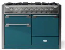
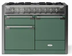
Elise
48 Dual Fuel
U111332 - 01b

DO NOT store or use gasoline or other ammable vapors and liquids in the
vicinity of this or any other appliance.
WHAT TO DO IF YOU SMELL GAS
DO NOT try to light any appliance.
DO NOT touch any electrical switch.
DO NOT use any phone in your building.
Follow the gas supplier’s instructions.
If you cannot reach your gas supplier, call the re department.
Installation and service must be performed by a qualied installer, service
agency or the gas supplier.
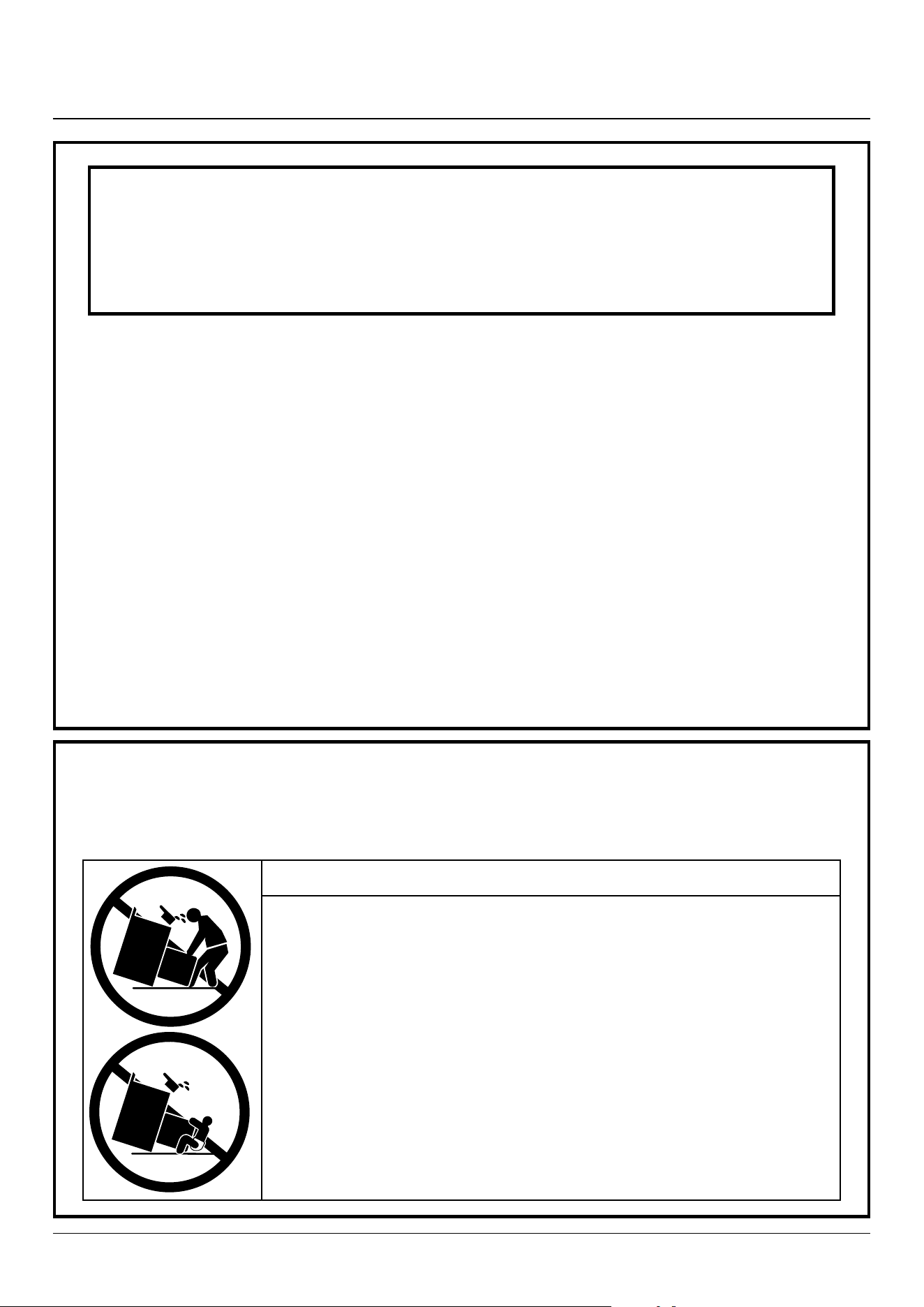
WARNING!
If the information in these instructions is not followed exactly, a re or
explosion may result, causing property damage, personal injury or death.
WARNING!
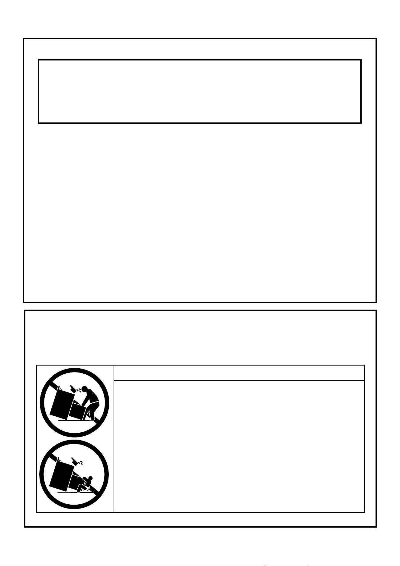
The anti-tip device supplied with this range must be installed when the appliance is installed. This will reduce the risk of
tipping of the appliance from abnormal usage or by excessive loading of the oven door.
ArtNo.030-0030 - RM tipping
warning symbols
WARNING!
• A CHILD OR ADULT CAN TIP THE RANGE AND BE KILLED.
• INSTALL ANTI-TIP BRACKET PACKED WITH RANGE - SEE INSTALLATION
INSTRUCTIONS.
• A CHILD OR ADULT CAN TIP THE RANGE AND BE KILLED
• ENGAGE THE RANGE TO THE ANTI-TIP DEVICE - SEE INSTALLATION
INSTRUCTIONS.
• RE-ENGAGE THE ANTI-TIP DEVICE IF THE RANGE IS MOVED.
• FAILURE TO DO SO CAN RESULT IN DEATH OR SERIOUS BURNS TO
CHILDREN OR ADULTS.
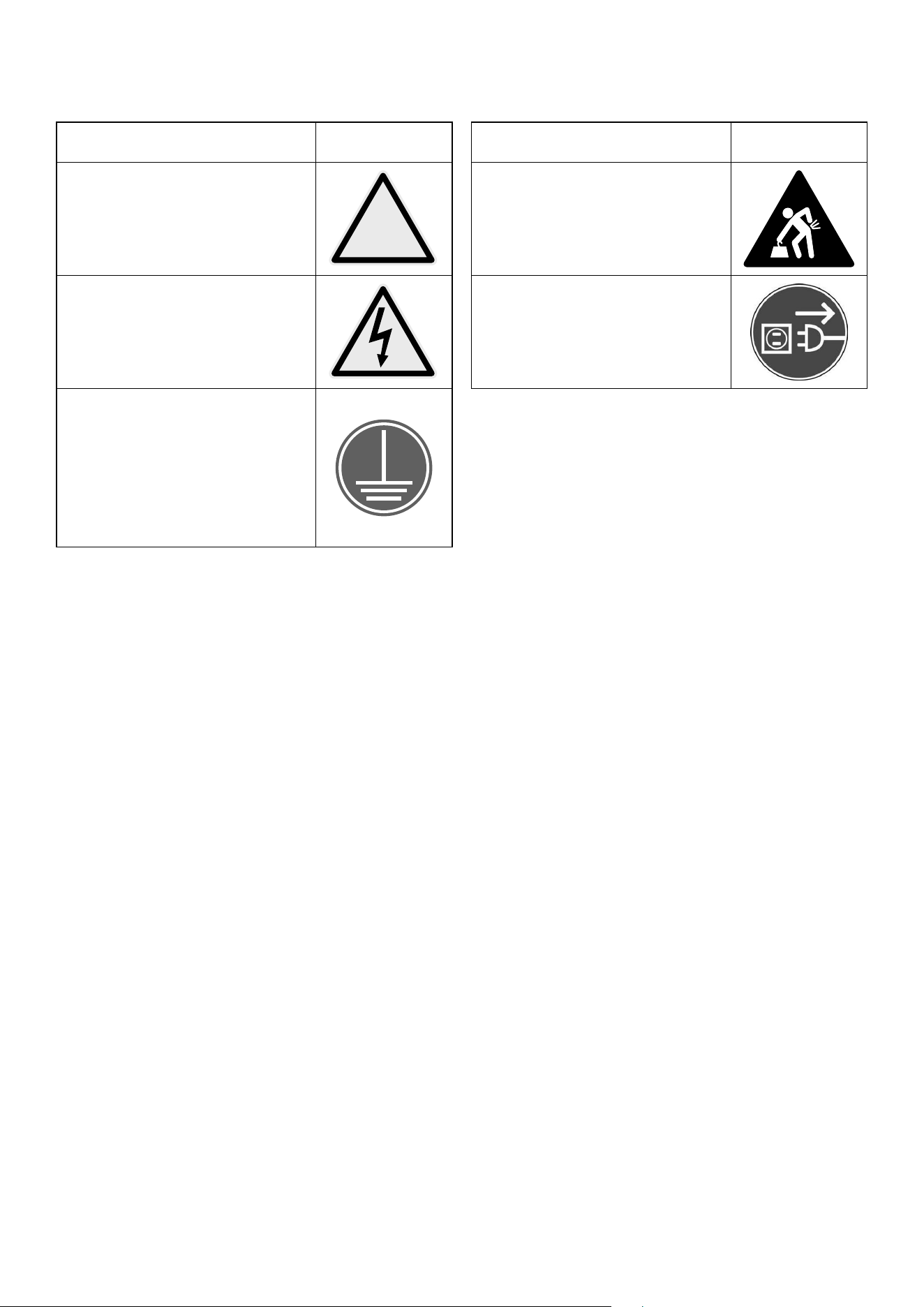
The following symbols are related to safety and are used on the product and throughout this manual.
Meaning / Description Symbol
WARNING / CAUTION
An appropriate safety instruction
should be followed or caution taken if
a potential hazard exists.
!
DANGEROUS VOLTAGE
To indicate hazards arising from
dangerous voltages.
PROTECTIVE EARTH (GROUND)
To identify any terminal which
is intended for connection to an
external conductor for protection
against electric shock in case of a
fault, or the terminal of a protective
earth (ground) electrode.
Meaning / Description Symbol
HEAVY
This product is heavy and reference
should be made to the safety
instructions for provisions of lifting
and moving.
DISCONNECT MAINS SUPPLY
Disconnect incoming supply before
inspection or maintenance.
1. Important safety information 1
2. Range overview 5
Cooktop 5
Wok burner 6
Wok cradle 6
Igniting cooktop burners without electricity 7
Glide out broiler system™ 7
Ovens 8
Multi-function oven 8
7-mode multi-function oven settings 8
Convection oven 9
Operating the ovens 9
Accessories 10
3. Using the Glide-out Broiler™ 12
4. Cooking tips 13
5. Cooking table 14
6. Cleaning your range 15
7. Troubleshooting 19
8. Installation Instructions 21
9. Service and parts 23
10. Installation safety instructions 24
11. Installation 26
12. Fitting the flue, flue vent
and side panels 29
Fitting the cooling fan box 30
Setting the height 30
Fitting the side panel rear retaining brackets 31
Fitting the obscuring trims 32
Fitting the side panels 32
Fitting the front mounting brackets 33
Fitting the bottom panel (toe kick) 34
Fitting the drawer 35
Fitting the restraint chain and anti-tip device 36
Completing the move 36
13. Removing the side panels 37
Removing the storage drawer 37
Removing the bottom panel (toe kick) 37
Removing the side panels 38
14. Gas connection 39
15. Electrical connection 42
16. Final fitting and checks 44
17. Circuit diagram 45
18. Technical data 46
Contents
1
Read all instructions before using this appliance. Save these
instructions for future reference.
Have your appliance properly installed and grounded by
a qualied technician. The installation must conform with
local codes, or in the absence of local codes, in accordance
with the National Fuel Gas Code, ANSI Z223. 1/NFPA 54 or, in
Canada, the Natural Gas and Propane Installation Code, CSA
B149. 1 and in addition the National Electrical Code NFPA 70
or the Canadian Electric Code, CSA C22. 1.
Install only as described in the installation section of this
book.
Ask your dealer to recommend a qualied technician and an
authorized repair service. Know how to disconnect the power
to the range at the circuit breaker or fuse box in case of an
emergency.
The anti-tip device supplied with this range must be installed
when the appliance is installed. This will reduce the risk of
tipping of the appliance from abnormal usage or by excessive
loading of the oven door or storage drawer.
Leaning, sitting or stepping on the doors or drawer of this
range can result in serious injuries and also cause damage to
the range. DO NOT allow anyone to climb, stand or hang on
any part of the range.
Important safety notice and warning
Prior to connection, the power cord should be
inspected for any damage. In the event of damage
please consult your electrical installer.
You must provide adequate clearances between the
range and adjacent combustible surfaces. Refer to
Installation Instructions.
Save the installation instructions for the local
electrical inspector’s use.
In case of fire
DO NOT use water on grease res. NEVER pick
up a aming pan. Turn the controls o. Smother a
aming pan on a cooktop burner by covering the
pan completely with a well tting lid or baking tray.
Isolate the power source, where it is safe to do so. If
available, use a multipurpose dry chemical or foam-
type re extinguisher.
If the re is in an oven pan, smother by closing the oven door.
Open doors and windows, or if a hood is installed, turn it on
to remove smoke and odor.
To prevent fire or smoke damage
Before using the range, make sure all the packing materials
have been removed.
Always keep the area around the range free from combustible
materials, gasoline, and other ammable vapors and liquids.
If the range is installed near a window, proper precautions
should be taken to prevent curtains from blowing over the
burners.
NEVER leave any items on the range cooktop. The
hot air from an oven vent may ignite ammable
items and may increase pressure in closed
containers, which may cause them to burst. Many
aerosol-type spray cans are EXPLOSIVE when
exposed to heat and may be highly ammable.
Avoid using or storing them near an appliance.
Many plastics will burn and most are damaged by heat. Keep
plastic items away from parts of the range that may become
warm or hot. DO NOT leave plastic items on the cooktop as
they may burn, melt or soften if left too close to a vent or a
lighted burner.
Storage should not be installed directly above a range. If
anything is stored above the range, it should be limited to
infrequently used items, which can be safely stored in an area
subjected to heat from a range. Temperatures may be unsafe
for some items such as volatile liquids, cleaners or aerosol
sprays.
Destroy the carton and plastic bags after unpacking the
range. NEVER allow children to play with packaging material.
NEVER use this appliance as a space heater to heat
or warm the room. Doing so may result in carbon
monoxide poisoning and overheating of the oven.
NEVER cover any slots, holes or passages in the
oven bottom or cover an entire rack with materials
such as aluminum foil. Doing so blocks airow
through the oven and may cause carbon monoxide
poisoning. Aluminum foil linings may also trap heat,
causing a re hazard.
It is recommended that this appliance is serviced
annually by a qualied service engineer.
DO NOT repair or replace any part of the appliance
unless specically recommended in this User
Manual. Always consult a qualied service engineer.
All other servicing should be done only by a qualied
technician, this may reduce the risk of personal injury and
damage to the range.
NEVER modify or alter the construction of a range by
removing leveling legs, panels, wire covers, anti-tip brackets/
screws, or any other part of the product.
DO NOT leave children alone.
Babies, toddlers and young children should not be allowed
near the range at any time. They should NEVER be allowed to
sit or stand on any part of the appliance.
DO NOT allow children to climb or play around the range.
The weight of a child on an open door may cause the range
to tip, resulting in serious burns or other injury.
1. Important safety information

2
Teach them not to play with controls or any other part of the
range.
NEVER store items of interest to children in the cabinets
above a range or on the backguard of a range; children
climbing on the range to reach them could be seriously
injured.
DO NOT use the oven for storage.
This instruction is based on safety considerations.
Flammable materials should not be stored in an oven, the
range storage drawer or near the cooktop burners. This
includes paper, plastic and cloth items, such as cookbooks,
plastic ware and towels, as well as ammable liquids. DO
NOT store explosives, such as aerosol cans, on or near the
appliance.
Flammable materials may explode and result in re or
property damage.
To avoid the risk of electrical shock, personal injury,
or death, make sure your range has been properly
grounded and always disconnect it from the main
power supply before servicing.
DO NOT touch cooktop burners or areas near burners.
Gas burners may be hot even if they have been o for some
time. Areas near the gas burners may become hot enough
to cause burns. During and after use, DO NOT touch, or let
clothing touch or other ammable materials contact the
burners or areas near the burners until they have had enough
time to cool. These areas include the cooktop and rear vent.
DO NOT touch heating elements or interior surfaces
of ovens.
Oven heating elements may be hot though they are dark in
color. Interior surfaces of an oven may become hot enough
to cause burns. During and after use, DO NOT touch, or
let clothing or other ammable materials touch heating
elements or interior surfaces of oven until they have had
enough time to cool.
Other range surfaces that may become hot enough to cause
burns are the broiler compartment and oven vent at the rear
of the range.
Wear suitable clothing
NEVER wear loose-tting or hanging clothes while using the
range. Be careful when reaching for items stored in cabinets
over the cooktop. Flammable material could be ignited if
brought into contact with a burner ame or hot surface and
may cause severe burns.
Use only dry potholders or oven
gloves
Moist or damp potholders on hot surfaces may result in
burns from steam. NEVER let a potholder touch hot heating
elements.
DO NOT use a towel or other bulky cloth in place of a glove.
They might catch re if they touch a hot surface.
Use dry oven gloves when applicable – using damp gloves
might result in steam burns when you touch a hot surface.
NEVER operate the range with wet hands.
Important safety notice and
warning
The California Safe Drinking Water and Toxic Enforcement Act
of 1986 (Proposition 65) requires the Governor of California to
publish a list of substances known to the State of California to
cause cancer or reproductive harm, and requires businesses
to warn customers of potential exposures to such substances.
This appliance contains or produces a chemical or chemicals
which can cause death or serious illness and which are known
to the state of California to cause cancer, birth defects or
other reproductive harm.
Users of this appliance are hereby warned that the burning
of gas can result in low-level exposure to some of the listed
substances, including benzene, formaldehyde and soot, due
primarily to the incomplete combustion of natural gas or
liquid petroleum (LP) fuels. Properly adjusted burners will
minimize incomplete combustion.
Exposure to these substances can also be minimized by
properly venting with an open window or using a ventilation
fan or hood.
To reduce the risk from substances in the fuel or from fuel
combustion, make sure this appliance is installed, operated,
and maintained according to the instructions in this booklet.
Conversion
This appliance is supplied set for Natural gas. A conversion kit
for Propane gas is supplied with the range.
Be sure your range is correctly adjusted by a qualied service
technician or installer for the type of gas (Natural or LP) that is
to be used. See the Installation section of these instructions.
WARNING!
These adjustments must be made by a qualied
service technician in accordance with the
manufacturer’s instructions and all codes and
requirements of the authority having jurisdiction.
Failure to follow these instructions could result in
serious injury or property damage. The qualied
agency performing this work assumes responsibility
for the conversion.
User servicing
DO NOT repair or replace any part of the appliance unless
specically recommended in the manual. All other servicing
should be referred to a qualied technician.

3
Cooktop burners
Quality of flames
On Natural Gas, the burners’ ames should be a blueish color
with, at most, a slightly yellowish fringe.
On Propane gas, the ames may be “softer”. The cooktop
burner ames may have a slightly yellowish tip.
If the ame burns with a long white tip, you should call for
service.
If the ame is distorted, check that the burner head is
correctly placed over the burner.
MAKE SURE THE FLOW OF COMBUSTION AND
VENTILATION AIR TO THE RANGE IS UNOBSTRUCTED.
Use the right size pan
This appliance is equipped with burners of dierent sizes.
Use utensils with at bottoms. DO NOT use unstable pans
and position the handles away from the edge of the cooktop.
Make sure the ames are under the pans. It is unsafe to let the
ames burn up the sides of the pan; the handle may get too
hot.
A proper relationship between the utensil and burner will
also improve eciency.
NEVER leave cooktop burners unattended at high
settings. Pans boiling over can cause smoking and
greasy spills may catch on re.
Protective Liners – DO NOT use aluminum foil to
line cooktop bowls or oven bottoms. Foil liners
may result in a risk of electric shock or re and will
damage the enamel nish. NEVER allow aluminum
foil to contact the heating elements.
DO NOT use hotplate protectors, foil or hotplate
covers of any description. These may aect the safe
use of your hotplate burners and are potentially
hazardous to health.
Glazed Cooking Utensils – Only certain types of
glass, glass/ceramic, ceramic, earthenware, or
other glazed utensils are suitable for range top
use without breaking due to the sudden change in
temperature.
Utensil handles should be turned inward and not
positioned over adjacent burners. If handles are
left over adjacent burners they will get hot and may
burn.
Use of aluminum pans may cause metallic marking
of the grates. This does not aect the durability of
the enamel and may be cleaned o with a metal
polish.
Ovens
Use care when opening the door.
Let hot air and steam escape before removing or
replacing food.
NEVER heat unopened food containers. Pressure
buildup may make the container burst and cause
injury.
Keep oven vent ducts unobstructed.
Placement of oven racks
Always place oven racks in the desired location while
the oven is cool. If the rack must be moved while the
oven is hot, DO NOT let the potholder contact the
hot heating element in the oven.
WARNING!THIS APPLIANCE IS PROVIDED WITH
ROLLERS TO FACILITATE MOVEMENT DURING
INSTALLATION. THE RANGE SHOULD NOT BE MOVED
AFTER INSTALLATION.
General safety instructions
This appliance must be installed by a competent person in
accordance with the installation instructions. The installation
must comply with the relevant regulations and also the local
electricity supply company requirements.
This appliance is designed for domestic cooking only. Use for
any other purpose could invalidate any warranty or liability
claim.
The use of a gas cooking appliance results in the production
of heat and moisture in the room in which it is installed.
Make sure that the kitchen is well ventilated: keep natural
ventilation holes open or install a mechanical ventilation
device, (mechanical extractor hood).
Prolonged intensive use of the appliance may call for
additional ventilation, for example opening a window, or
more eective ventilation, for example increasing the level of
mechanical ventilation where present.
This appliance should not be installed with any
ventilation system that blows air downward toward
the gas cooking appliance. This type of ventilation
system may cause ignition and combustion
problems with the gas cooking appliance, resulting
in personal injury or unintended operation.
Ventilating systems that direct the air upwards can
be used.
The range should be serviced by a qualied service engineer
and only approved parts used. Have the installer show you
the location of the range circuit breaker. Mark it for easy
reference. Always allow the range to cool and then switch it
o at the circuit breaker before cleaning or carrying out any
maintenance work, unless specied otherwise in this guide.
All parts of the range become hot with use and will
retain heat even after you have stopped cooking.

4
Take care when touching the range in order to
minimize the possibility of burns; always be certain
that the controls are in the OFF position and that it is
cool before attempting to clean the range.
Clean with caution. If a wet sponge or cloth is used to wipe
spills on a hot surface, be careful to avoid steam burns. Some
cleaners can produce noxious fumes if applied to a hot
surface.
Clean only parts listed in this guide.
In the interests of hygiene and safety, the range should be
kept clean at all times as a build up of fats and other food
stu could result in a re.
Always keep combustible wall coverings or curtains etc. a safe
distance away from your range.
DO NOT spray aerosols in the vicinity of the range
while it is in use.
DO NOT store or use combustible materials, or ammable
liquids in the vicinity of this appliance.
Take great care when heating fats and oils, as they will ignite
if they get too hot.
Use a deep fat thermometer whenever possible to prevent
overheating fat beyond the smoking point.
NEVER leave a deep fry pan unattended. Always
heat fat slowly, and watch as it heats. Deep fry pans
should be only a maximum of one third full of fat.
Filling the pan too full of fat can cause overspill
when food is added. If you use a combination of oils
or fats in frying, stir them together before heating,
or as the fats melt.
Foods for frying should be as dry as possible. Frost on frozen
foods or moisture on fresh foods can cause hot fat to bubble
up and over the sides of the pan. Carefully watch for spills or
overheating of foods when frying at high or medium high
temperatures. NEVER try to move a pan of hot fat, especially
a deep fry pan. Wait until the fat is cool.
When an oven is on, DO NOT use the top of the ue (the
round holes along the back of the range) for warming plates,
dishes, drying dish towels or softening butter.
When using an electrical appliance near the cooktop, be sure
that the cord of the appliance does not come into contact
with the cooktop.
Take care that no water seeps into the appliance.
Make sure that your kitchen is well ventilated at all times. Use
extractor fans or hoods when installed.
The range is designed for cooking foods only and must not
be used for any other purpose.
The oven should NOT be used for heating the kitchen, not
only does this waste fuel but the control knobs may become
overheated.
When the oven is on DO NOT leave the oven door open for
longer than necessary.
The specication of this range should not be altered.
This appliance is heavy, take care when moving it.
When the range is not in use, ensure that the control knobs
are in the OFF position.
5
ArtNo.110-0045 - 120DF - Mercury door clearances
ArtNo.215-0009 - 110 Elan DF
A
B
C
D
F
G
E
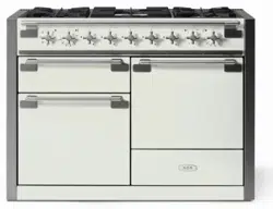
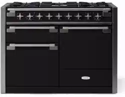
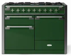
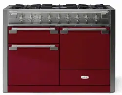
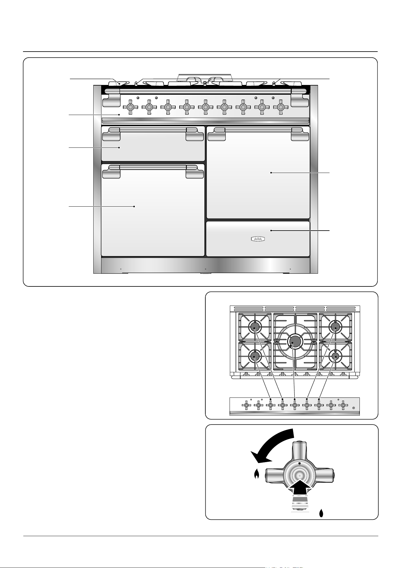
The 48” dual fuel range (Fig. 2.1) has the following features:
A. 5 gas burners including 1 wok burner (Fig. 2.2)
B. A control panel
C. Glide Out Broiler System™
D. Main multi-function oven
E. Interlocking cast iron grates
F. Convection oven
G. Storage drawer
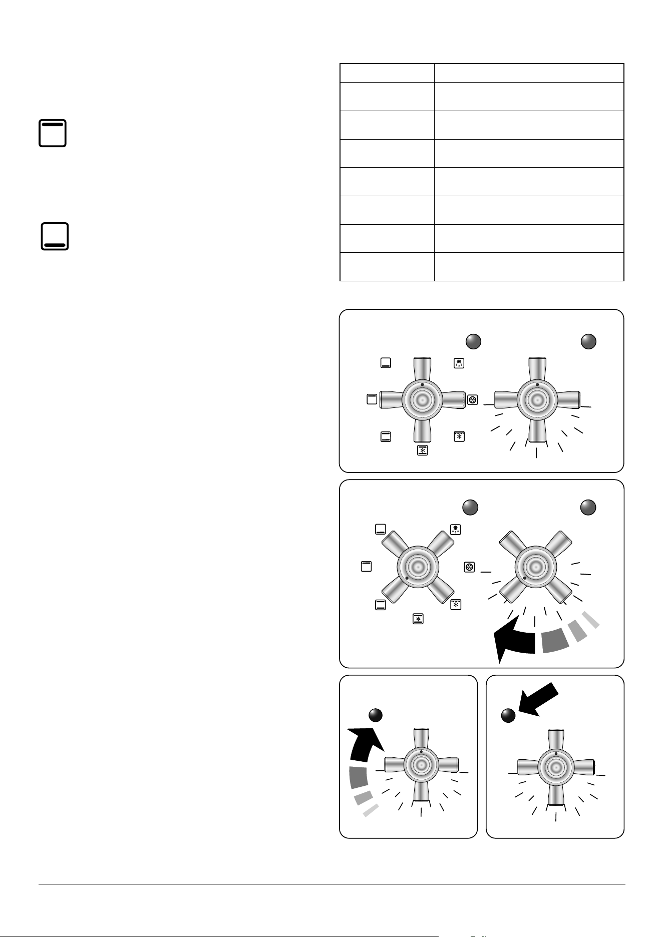
Cooktop
The icon by each of the central knobs indicates which burner
that knob controls.
Each burner has a Flame Supervision Device (FSD) that
prevents the ow of gas if the ame goes out.
When a knob is pressed in, sparks will be made at each burner
ignitor – this is normal. DO NOT attempt to disassemble
or clean around any burner while another burner is on,
otherwise an electric shock could result.
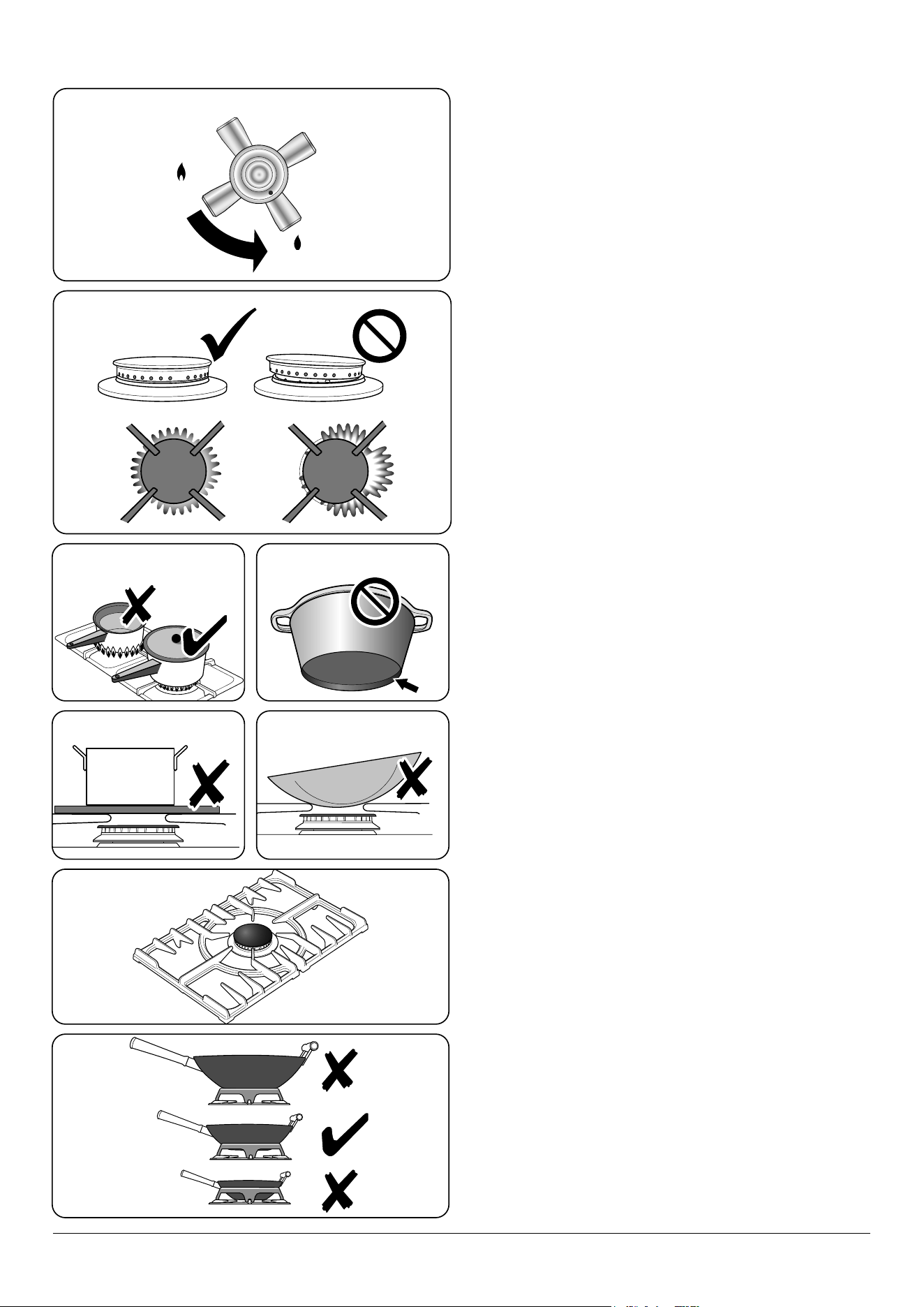
To light a burner, push in the selected burner control knob
and turn it to the high position, as indicated by the large
ame symbol (
) (Fig. 2.3). The igniter should spark and light
the gas. Keep the knob pressed in for 10 seconds until the
burner remains lite.
0
2. Range overview
Fig. 2.1
Fig. 2.2
Fig. 2.3
DocAUS.020-0004 - Overview - 110DF - Elan
6
0
ArtNo.311-0030 - Burner head fitting
When you release the control knob, if the burner goes out,
the FSD has not been bypassed. Turn the control knob to the
OFF position and wait for one minute before you try again,
this time making sure to hold in the control knob for slightly
longer.
Adjust the ame height to suit by turning the knob counter-
clockwise (Fig. 2.4). On this range the low position is beyond
high, not between high and o.
If a burner ame goes out, turn o the control knob and leave
it for one minute before relighting it.
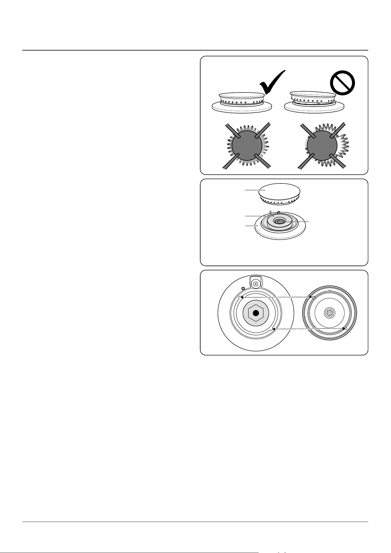
If the ame is distorted, check that the burner head is
correctly placed over the burner base (Fig. 2.5)
If the ame burns with a long white tip you should call for
service.
Make sure that the ames are under the pans. Using a lid will
help the contents boil more quickly (Fig. 2.6).
Large pans should be spaced well apart.
Pans and kettles with concave bases or down-turned base
rims should not be used (Fig. 2.7).
Simmering aids, such as asbestos or mesh mats, are
NOT recommended (Fig. 2.8). They will reduce burner
performance and could damage the burner grates.
You should also avoid using unstable and misshapen pans
that may tilt easily, and pans with a very small base diameter,
e.g. single egg poachers (Fig. 2.9).
The minimum recommended pan diameter is 6 5/6” (160 mm).
The maximum allowable pan base diameter is 10 ¼” (260
mm). Minimum size wok pan at top is diameter 13 3/16” (335
mm).
DO NOT use cooking vessels on the burners that overlap the
edges.
Wok burner
The wok burner is designed to provide even heat over a large
area. Ideal for large pans and stir-frying (Fig. 2.10).
For heating smaller pans, the aforementioned burners may
be more ecient.
You should wipe the enamel top surface of the range around
the hotplate burners as soon as possible after spills occur. Try
to wipe them o while the enamel is still warm.
NOTE: The use of aluminium pans may cause metallic
marking of the burner grates. This does not aect the
durability of the enamel and may be cleaned o with an
appropriate metal cleaner.
Wok cradle
The wok cradle is designed to t a 13 ¾” (350 mm) wok. If you
use a dierent wok, make sure that it ts the cradle. Woks vary
very widely in size and shape. It is important that the wok sits
down on the burner grates – however, if the wok is too small,
the cradle will not support it properly (Fig. 2.11).
We recommend a minimum wok pan of 13 3/16” (335 mm). The
ArtNo.311-0002 Pan with rim
ArtNo.311-0001 Right pans gas
Art No. 311-0003 Simmer aids
ArtNo.311-0004 Tipping wok
ArtNo.311-0006 Correct wok sizes
Fig. 2.4
Fig. 2.5
Fig. 2.7
Fig. 2.9
Fig. 2.6
Fig. 2.8
Fig. 2.10
Fig. 2.11
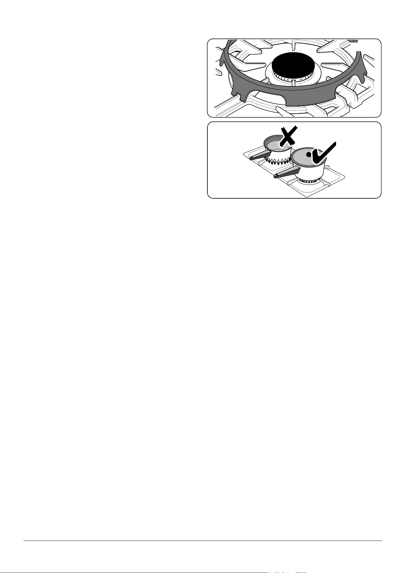
7
cradle should be used on the wok burner only. When you
t the cradle, make sure that it is supported properly on a
burner grate and the wok is sitting level in the cradle
(Fig. 2.12).
The cradle will get very hot in use – allow plenty of time for it
to cool before you pick it up.
Igniting cooktop burners without
electricity
If there is a power failure, the cooktop burners can be lit with
a match.
1. Hold a burning a match ½ inch from the burner head
keeping your hand as far horizontally away from the
burner as possible.
2. Push and turn burner control knob to HI/ lighting
position. As soon as the burner ame lights move your
hand away. With your other hand, keep holding the
knob pressed for a few seconds so that the burner safety
device can ‘sense’ the heat of the ame.
3. Make sure that the ames are under the pans
(Fig. 2.13). Using a lid will help the contents boil more
quickly.
4. Turn burner control knob to OFF position when nished.
Glide out broiler system™
When the trivet has been removed from the broiler
pan, please ensure that the broiler pan and cradle
are fully returned into the broiler chamber. The
broiler door MUST remain open.
1. For best results, slide the carriage back into the
broiler chamber and preheat the appropriate part(s)
of the broiler for two minutes. The broiler trivet can
be removed and the food placed on it while you are
waiting for the broiler to preheat.
2. DO NOT leave the broiler oven door open for more than
a few moments without the broiler pan underneath it ,
otherwise the knobs may become hot.
3. Preheat the broiler chamber prior to placing the food on
the trivet. Once the trivet is placed back into the broiler
pan, place the broiler pan back into the broiler carriage.
Slide the carriage back into the broiler chamber.
Accessible parts may be hot when the broiler is in
use. Young children should be kept away.
ArtNo.311-0001 Right pans gas
Fig. 2.13
Fig. 2.12
8
Ovens
Please refer to (Fig. 2.1).
References to ‘left-hand’ and ‘right-hand’ ovens apply as
viewed from the front of the appliance.
The left-hand oven is a multi-function oven, while the right-
hand oven is a fan oven.
Multi-function oven
As well as the oven fan and fan element, they are tted
with two extra heating elements, one visible in the top of
the oven and the second under the oven base. Take care to
avoid touching the top element and element deector when
placing or removing items from the ovens.
The multi-function oven has 3 main cooking functions: fan,
fan assisted and conventional cooking. These functions
should be used to complete most of your cooking.
The browning element and base heat can be used in the
latter part of the cooking process to ne tune the results to
your particular requirements.
Use fanned broiling for all your broiling needs and defrost to
safely thaw small items of frozen food.
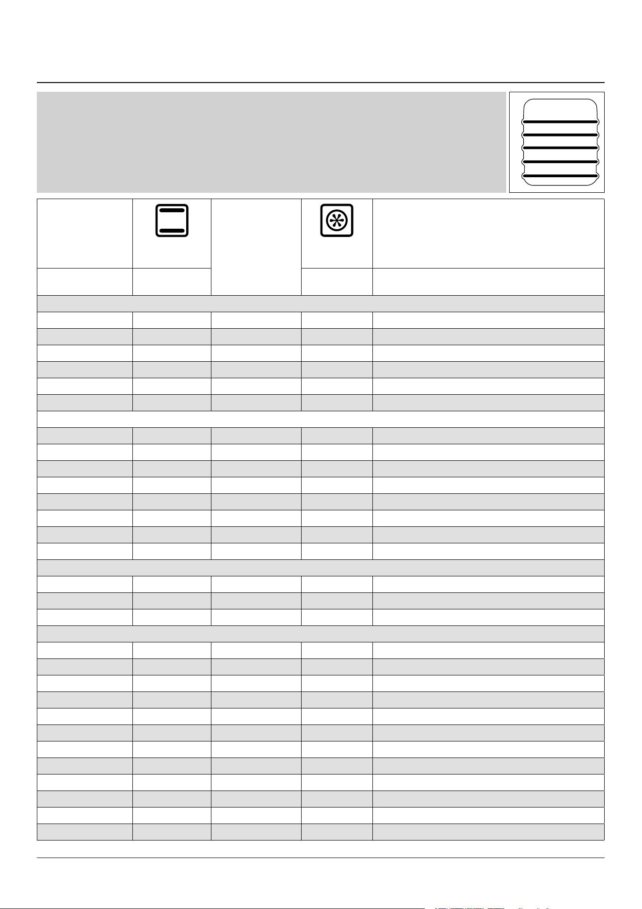
Table 2.1 gives a summary of the multi-function modes.
The multi-function ovens have many varied uses. We suggest
you keep a careful eye on your cooking until you are familiar
with each function. Remember – not all functions will be
suitable for all food types.
Please remember that all ranges vary – temperatures in your
new ovens may dier to those in your previous range.
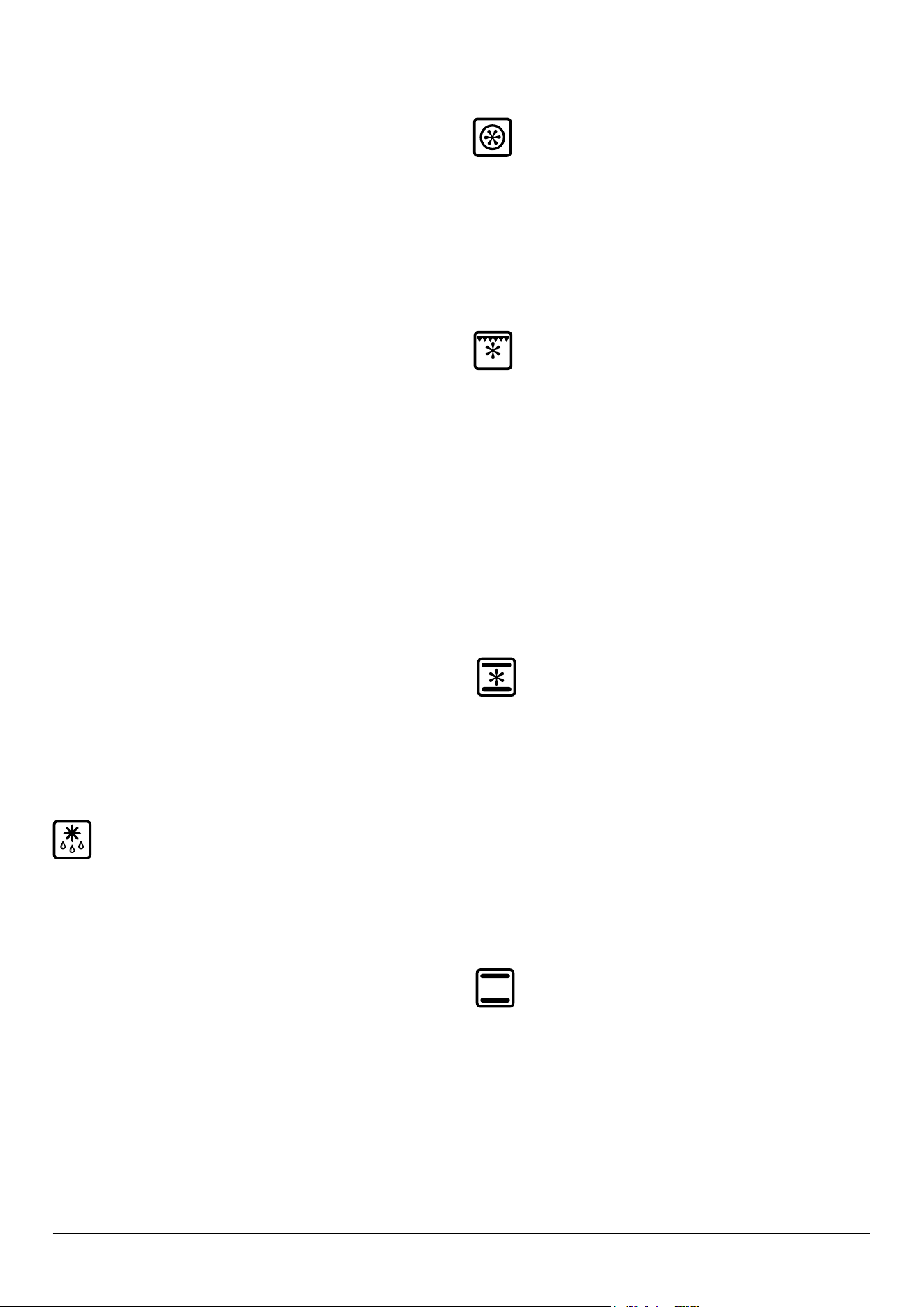
7-mode multi-function oven
settings
Thaw and serve
This function operates the fan to circulate cold air
only. Make sure the temperature control is OFF and
that no heat is applied. This enables small items such
as desserts, cream cakes and pieces of meat, sh and poultry
to be defrosted.
Defrosting in this way speeds up the process and protects the
food. Pieces of meat, sh and poultry should be placed on a
rack, over a tray to catch any drips. Be sure to wash the rack
and tray after defrosting.
Defrost with the oven door closed.
Large items, such as whole chickens and joints should not be
defrosted in this way. We recommend this be carried out in a
refrigerator.
Defrosting should not be carried out in a warm oven or when
an adjoining oven is in use or still warm.
Make sure that dairy foods, meat and poultry are completely
defrosted before cooking.
True convection oven
This function operates the fan and the heating
element around it. An even heat is produced
throughout the oven, allowing you to cook large
amounts quickly.
Convection cooking is particularly suitable for batch baking
on several shelves at one time and is a good ‘all-round’
function. It may be necessary to reduce the temperature by
approximately 25 °F/10°C for recipes previously cooked in a
conventional oven.
Convection broiling
This function operates the fan whilst the top element
is on. It produces a more even, less erce heat than
conventional broiling. For best results, place the food
to be broiled, on a grid over a roasting tin, which should be
smaller than a conventional broiling pan. This allows greater
air circulation. Thick pieces of meat or sh are ideal for
convection broiling, as the circulated air reduces the
erceness of the heat from the broiler.
The oven door should be kept closed while broiling is in
progress, saving energy.
You will also nd that the food needs to be watched and
turned less. Preheat this function before cooking.
For best results we recommend that the broiling pan is not
located on the uppermost shelf.
Convection assisted oven
This function operates the fan, circulating air heated
by the elements at the top and the base of the oven.
The combination of fan and conventional cooking
(top and base heat) makes this function ideal for cooking
large items that need thorough cooking, such as a large meat
roast.
It is also possible to bake on two shelves at one time,
although they will need to be swapped over during the
cooking time, as the heat at the top of the oven is greater
than at the base, when using this function.
This is a fast intensive form of cooking; keep an eye on the
food cooking until you have become accustomed to this
function.
Conventional oven (Top and Base Heat)
This function combines the heat from the top and
base elements. It is particularly suitable for roasting
and baking pastry, cakes and biscuits.
Food cooked on the top shelf will brown and crisp faster
than on the lower shelf, because the heat is greater at the
top of the oven than at the base, as in ‘Fan Assisted’ function.
Similar items being cooked will need to be swapped around
for even cooking. This means that foods requiring dierent
temperatures can be cooked together, using the cooler zone
in the lower half of the oven and hotter area to the top.
The exposed top element may cook some foods too quickly,
so we recommend that the food be positioned in the lower
9
half of the oven to cook. The oven temperature may also need
to be lowered.
Browning
This function uses the element in the top of the oven
only. It is a useful function for the browning or
nishing of pasta dishes, vegetables in sauce,
and lasagna For best results, the item to be browned should
be hot before switching to the top element.
Warming
This function uses the base element only. It will crisp
up your pizza or quiche base or nish o cooking the
base of a pastry case on a lower shelf. It is also a
gentle heat, good for slow cooking of casseroles in the
middle of the oven or for plate warming.
The Browning and Base Heat functions are useful additions
to your oven, giving you exibility to nish o items to
perfection.
Convection oven
The right-hand oven is a convection oven that circulates hot
air continuously, which means faster, more even cooking.
The recommended cooking temperatures for a convection
oven are generally lower than a conventional oven. It may be
necessary to reduce the temperature by approximately
25 °F/10°C for recipes previously cooked in a conventional
oven.
NOTE: Please remember that all ranges vary so temperatures
in your new ovens may dier to those in your previous range.
Operating the ovens
Operating the multi-function oven
1. The multi-function oven has two controls: a function
selector and a temperature setting knob (Fig. 2.14).
2. Turn the function selector control to a cooking function.
Fig. 2.15 shows the control set for convectional oven
cooking.
3. Turn the oven temperature knob to the temperature
required (Fig. 2.15).
The oven heating light will glow until the oven has reached
the temperature you selected. It will then cycle on and
o during cooking as the oven maintains the selected
temperature.
Operating the convection oven
1. Turn the oven knob to the desired temperature
(Fig. 2.16).
2. The oven indicator light will glow until the oven has
reached the temperature selected. It will then cycle on
and o during cooking (Fig. 2.17).
Function Use
Defrost
To thaw small items in the oven
without heat.
Convection
A full cooking function, even heat
throughout, great for baking.
Convection
broiling
Broil meat and sh with door closed.
Fan assisted
A full cooking function good for
roasting and baking.
Conventional
A full cooking function for roasting and
baking in the lower half of the oven.
Browning
To brown and crisp cheese topped
dishes.
Base heat
To crisp up the bases of quiche, pizza
or pastry.
0
0
150
200
250
300
350
400
450
150
200
250
300
350
400
450
0
150
200
250
300
350
400
450
0
0
0
150
200
250
300
350
400
450
Fig. 2.14
Fig. 2.15
Fig. 2.16 Fig. 2.17
Table 2.1
10
1
2
3
Fig. 2.22
Fig. 2.23 Fig. 2.24
Accessories
Oven shelves
The range is supplied with the following:
• 2 standard shelves (Fig. 2.18)
• 1 drop shelf (Fig. 2.19)
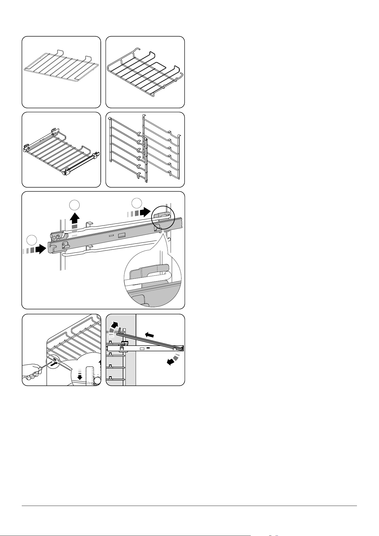
• 2 telescopic shelves with runners (Fig. 2.20)
• 2 sets of side supports (Fig. 2.21)
The oven shelves are retained when pulled forward but can
be easily removed and retted.
To fit the telescopic shelf runners
1. With the runner arm in the closed position locate the
opening of the upper rear slot onto the side support
(Fig. 2.22). DO NOT locate any further than the
opening at this point.
2. Lift the front of the runner arm to locate the front slot
against the side support (Fig. 2.22).
3. Push the runner arm towards the rear of the oven. The
catch at the front will lift and drop to secure the runner
arm in place (Fig. 2.22).
To fit a shelf to the telescopic shelf runners
Slide the telescopic runners forward until they stop. Holding
the shelf above the runners, tilt the front downward and
locate into the front of the runners. Lay the shelf at. Press on
the rear of the shelf to secure in place.
To remove a shelf from the telescopic shelf runners
1. Slide the shelf out on the runners. While holding one
of the runners securely, carefully lift the rear of the
shelf upwards: the shelf will spring clear of the central
restraining tab. Repeat for the opposite side of the shelf.
2. NOTE: To aid the removal of the shelf you can insert a
suitable at tool through the opening in the side of the
runners and lever the shelf clear (Fig. 2.23).
3. Tilt the front of the shelf downwards and then lift clear
of the runners (Fig. 2.24).
To remove the telescopic shelf runners
1. Firstly, remove the shelf as in the ‘To Remove a Shelf
from the Telescopic Shelf Runners’ section page 10.
2. Place a nger on the underside of the telescopic runner
and lift.
3. Open the catch on top of the runner and pull the runner
forward and down to remove.
Fig. 2.18 Fig. 2.19
Fig. 2.20 Fig. 2.21
11
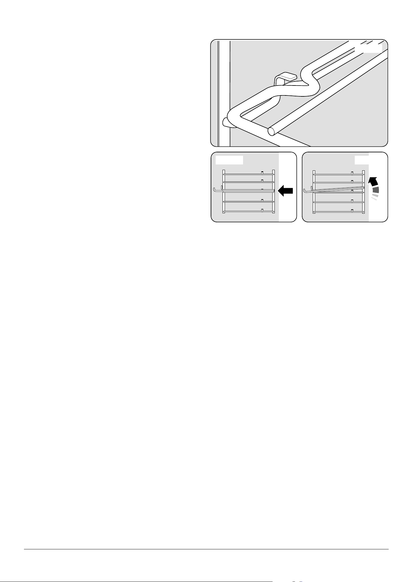
To remove and fit a shelf to the side supports
1. The shelf has a small kink on either side (Fig. 2.25).
To remove the shelf, line these up with the stops in
the shelf support (Fig. 2.26). Lift the front of the shelf
upward so that it will pass over the shelf stop and then
pull it forward (Fig. 2.27).
2. Fit in the reverse order, making sure to push it fully back.
To remove and refit the ladder shelf supports
1. Lift the ladder support hooks out of the two locating
holes in the oven side (or divider) before lifting the
support clear of the bottom ladder restraint.
2. Ret by inserting the bottom of the ladder into the
restraint before tting the hooks through the locating
holes.
Storage
The bottom drawer is for storing cooking utensils.
To open, simply push the drawer in and release.
Flammable materials should not be stored in an oven, the
range storage drawer or near the cooktop burners. This
includes paper, plastic and cloth items, such as cookbooks,
plasticware and towels, as well as ammable liquids. DO
NOT store explosives, such as aerosol cans, on or near the
appliance.
Flammable materials may explode and result in re
or property damage.
Fig. 2.25
Fig. 2.26 Fig. 2.27
12
Nearest to the element
Middle High
Middle Low
Furthest from the element
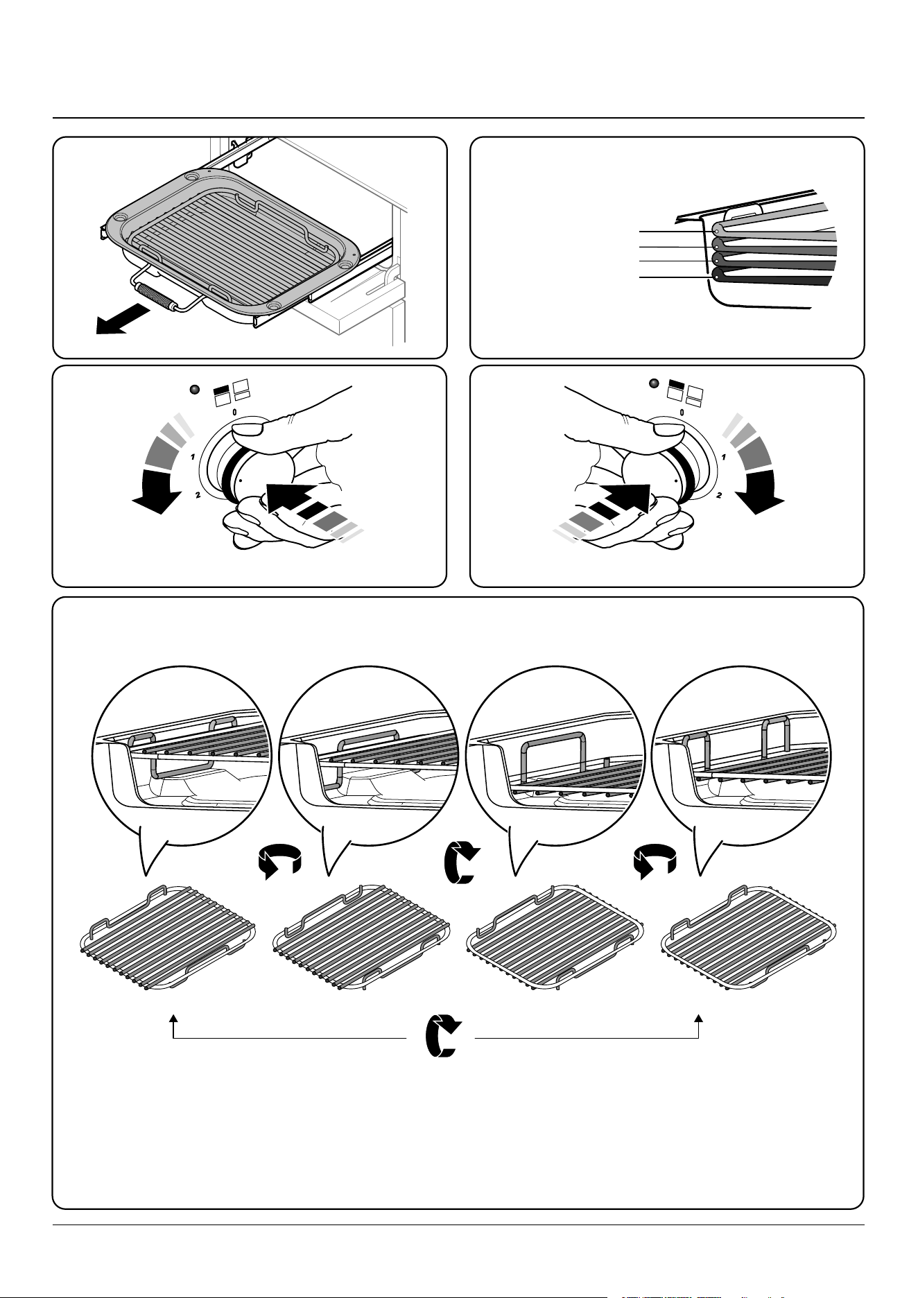
3. Using the Glide-out Broiler™
180o
180o 180o 180o
Nearest to the element Middle LowMiddle High Furthest from the element
Four grill height positions
Four grill height positions
refer to Fig. 3.5
To switch on both element
Fig. 3.1 Fig. 3.2
To switch on the right half element
Fig. 3.3 Fig. 3.4
Fig. 3.5
Cooking suggestions
1. Nearest to the element – Toast, steak.
2. Middle high – grilled cheese, sliced vegetables, Canadian peameal bacon.
3. Middle low – sh llets, vegetable kebabs.
4. Furthest from the element – whole sh, thick pork chops, chicken breasts, chicken or beef kebabs.
NOTE: A short term cooking process has to be supervised continously.
DocAUS.020-0004 - Overview - 110DF - Elan
13
Cooking with a multi-function oven
REMEMBER: not all modes are suitable for all food types. The
oven cooking times given are intended as a guide only.
General oven tips
The wire racks should always be pushed rmly to the back of
the oven.
Baking trays with food cooking on them should be placed
level with the front edge of the oven’s wire racks. Other
containers should be placed centrally. Keep all trays and
containers away from the back of the oven as overbrowning
of the food may occur.
When the oven is on, DO NOT leave the door open for
longer than necessary, otherwise the knobs may get very
hot.
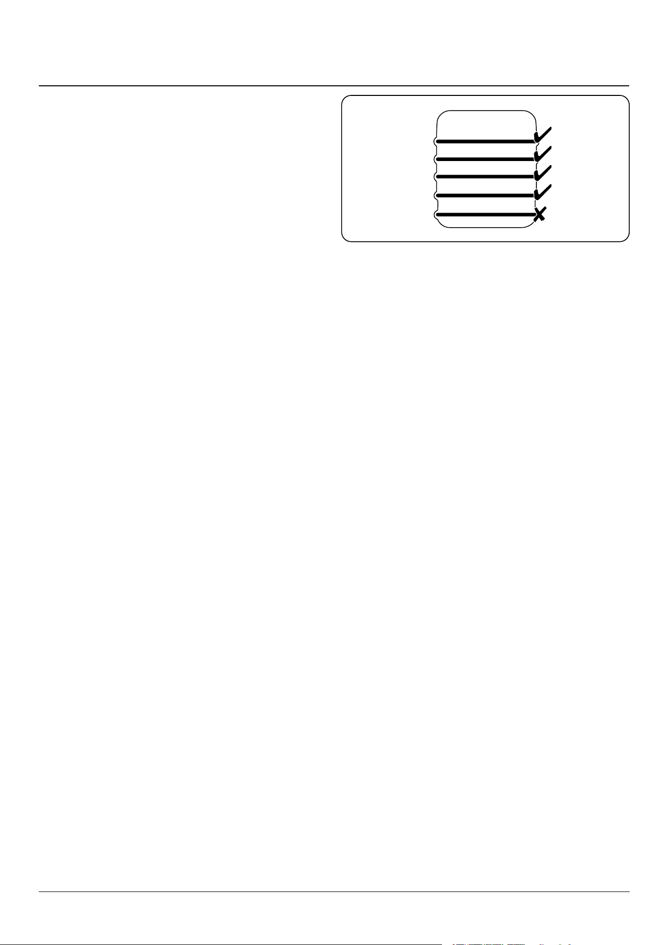
• The telescopic racks with runners can be utilized on
levels 2, 3, 4 and 5. It is not possible to utilize the rack on
level 1 (Fig. 4.1).
• Always leave a ‘finger’s width’ between dishes on the
same rack. This allows the heat to circulate freely around
them.
• To reduce fat splashing when you add vegetables to hot
fat around a roast, dry them thoroughly or brush lightly
with cooking oil.
• Where dishes may boil and spill over during cooking,
place them on a baking tray.
• If you want to brown the base of a pastry dish, preheat
the baking tray for 15 minutes before placing the dish in
the center of the tray.
4. Cooking tips
ArtNo.050-0019 - Albertine SC
- Shelf position
1
2
3
4
5
Fig. 4.1
14
5. Cooking table
ArtNo.050-0019 - Albertine SC
- Shelf position
1
2
3
4
5
The oven control settings and cooking times given in the table below are intended to be used as a
guide only. Individual tastes may require the temperature to be altered to provide a preferred result.
Food is cooked at lower temperature in a fan oven than in a conventional oven. When using recipes,
reduce the fan oven temperature by 25 °F and the cooking time by 5-10 minutes. The temperature in
the fanned oven does not vary with height in the oven so you can use any shelf.
ArtNo.030-0015 - Top & Bottom Symbol
Conventional
oven
Rack position
for conventional
cooking
ArtNo.030-0016 - MF Fan Oven Symbol
Convection
oven
Temperature
°F
Temperature
°F
Approximate cooking time
Meat
Beef (no bone) 300 2 300 30-35 minutes per 1 lb + 30-35 minutes
375 2 375 20-25 minutes per 1 lb + 20-25 minutes
Lamb 300 2 300 30-35 minutes per 1 lb + 30-35 minutes
375 2 375 20-25 minutes per 1 lb + 20-25 minutes
Pork & veal 300 2 300 35-40 minutes per 1 lb + 35-40 minutes
375 2 375 25-30 minutes per 1 lb + 25-30 minutes
Poultry
Chicken 300 2 300 20-25 minutes per 1 lb + 20-25 minutes
375 2 375 15-20 minutes per 1 lb + 15-20 minutes
Turkey (slow cook) 300 2 300 25-30 minutes per 1 lb + 25-30 minutes
375 2 375 20 minutes per 1 lb + 20 minutes
Turkey (fast cook) 300 2 300 20 minutes per 1 lb + 20 minutes
375 2 375 15 minutes per 1 lb + 15 minutes
Duck/Duckling 300 2 300 20 minutes per 1 lb
Casserole 300 2 300 2-4 hours, according to recipe
Fish
Fillet 350 2 350 15-20 minutes
Whole 350 2 350 Whole 10 minutes per 1 lb + 10 minutes
Steak out 350 2 350 Steaks according to thickness
Desserts
Cup cake 325 2 325 20 minutes
Scone 375 2 375 15 minutes
Deep apple pie 350 2 350 45 minutes
Plate tart 350 2 350 45 minutes
Fruit cake 8” x 3. 5” 275 2 275
1¾-2 hours
Pu pastry 400 2 400 15-40 minutes according to size
Angel food cake 325 2 325 50-60 minutes
Brownies 350 2 350 25-30 minutes
Muns 350 2 350 25-30 minutes
Cookies 350 2 350 15-20 minutes
Pound cakes 350 2 350 40-60 minutes
Bread 375 2 375 20-30 minutes
DocNo. 031-0004 - Cooking table - electric & fan single cavity
15
Essential information
Before thorough cleaning, turn o the circuit
breaker. Allow the range to cool.
After cleaning remember to switch on the circuit
breaker before using the range.
NEVER use paint solvents, caustic cleaners,
biological powders, bleach, chlorine based bleach
cleaners, coarse abrasives or salt.
DO NOT mix dierent cleaning products – they may
react together with hazardous results.
Recommended cleaning materials are shown in Table 6.1.
Cleaning the range – daily care
Cleaning the range is not a welcomed chore, but it has to be
done to maintain eciency and appearance. Remember it
is better to wipe up any spills as they occur, this will prevent
them burning on and becoming more dicult to remove
later.
Make sure the ow of combustion and ventilation air
to the range is unobstructed – for example, by build-
up of fats or grease.
If the ame is distorted, check that the burner head is
correctly placed over the burner base (Fig. 6.1).
If the ame burns with a long white tip you should call for
service.
Cleaning for spills
For spills and boil-overs that occur while cooking, as soon
as possible turn o the burner and allow it to cool. DO NOT
clean until the area is completely cooled down. Wipe up spills
as soon as possible.
DO NOT allow surplus water to seep into the range.
Cooktop burners
The burner heads and caps can be removed for cleaning.
Make sure they are absolutely dry before replacing.
When replacing burner head, make sure this locates properly
within the base (Fig. 6.2). If you look at the bottom of the
burner head you will see two ‘pips’; these t into the two
notches in the burner base (Fig. 6.3). Check burner ports are
not blocked. If blockage occurs, remove stubborn particles
using a piece of fuse wire.
6. Cleaning your range
ArtNo.311-0028 - Burner head off
A
C
B
D
ArtNo.311-0029 - Burner base & head alignment
ArtNo.311-0030 - Burner head fitting
A - Burner head, B - Burner ring, C - Base, D - Brass venturi
Fig. 6.1
Fig. 6.2
Fig. 6.3
16
Stainless steel main top
Lift away pots or pans from main top. Remove grates from
spillage area and carefully place in a sink of warm soapy
water. Wipe loose debris from main top. Avoid using any
abrasive cleaners including cream cleaners on brushed
stainless steel surfaces. For best results use a liquid detergent
cleaner. Rinse with cold water and thoroughly dry with
a clean, soft cloth. Make sure all parts are dry before
repositioning.
NEVER use caustic or abrasive cleaners as these will
damage the surface.
DO NOT use a griddle on your range.
Control panel and oven doors
Avoid using any abrasive cleaners including cream cleaners,
on brushed stainless steel surfaces. For best results use liquid
detergents.
The control panel and control knobs should only be cleaned
with a soft cloth wrung out in clean hot soapy water – but
take care that no surplus water seeps into the appliance. Wipe
with a clean dampened cloth then polish with a dry cloth. The
oven doors should only be cleaned with a soft cloth wrung
out in clean hot soapy water.
Ovens
The side panels can be removed for cleaning and for cleaning
behind them.
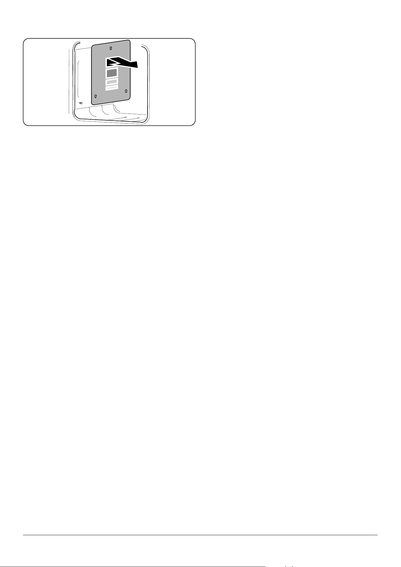
Removing the panels to clean the
enamel interior
Some of the lining panels can be removed for cleaning.
If you wish to clean the enamel interior of the oven, you
will need to remove the shelves before removing the ‘Cook
& Clean’ panels . You do not have to remove the support
brackets to remove the panels. Lift each panel upward and
slide forward o the support brackets (Fig. 6.4).
Once the panels have been removed, the oven enamel
interior can be cleaned.
Ret in the reverse order.
Fig. 6.4
17
Grill pan
Grill tray
Telescopic rail
Telescopic rail
ArtNo.331-0005 Removing the grill rail
1 2 3
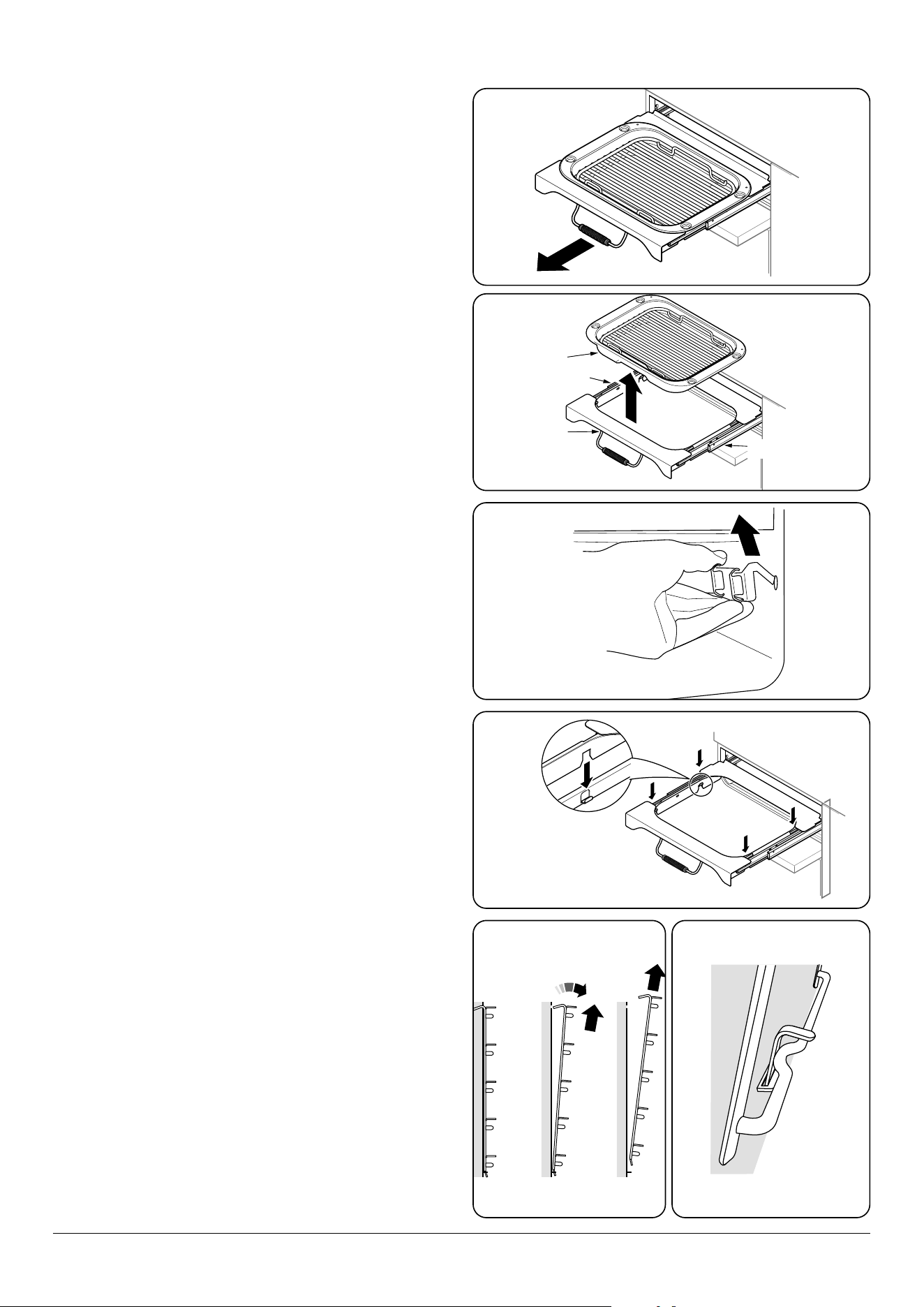
Glide-out broiler™
Before you remove any of the broiler parts for
cleaning, make sure that they are cool, or use oven
gloves.
Wash the broiler pan, trivet and broiler tray in hot soapy
water. Alternatively, wash the broiler pan in a dishwasher.
After broilling meats or any foods that soil, leave to soak for
a few minutes in the sink immediately after use. Stubborn
particles may be removed from the trivet by using a nylon
brush.
1. To remove the broiler pan, pull the tray assembly
forwards (Fig. 6.5) and then lift the broiler pan clear of
the broiler tray assembly (Fig. 6.6).
2. For safety, push the broiler tray back into the broiler
chamber.
3. If you need to remove the telescopic runners to allow
cleaning of the broiler chamber, rst remove the
broiler tray then you can unhook them from the broiler
chamber sides (Fig. 6.7).
4. Wipe the sides clean with a soft cloth and mild
detergent.
DO NOT put the side runners in a dishwasher.
5. Once you have nished, hook the side rails back onto
the sides of the chamber. Pull the telescopic rails out
and t the broiler tray onto them, making sure to locate
the cut-outs onto the telescopic runner tabs (Fig. 6.8).
6. Replace the broiler pan.
Oven shelf supports
The shelf supports on the oven sides can be removed for
cleaning.
Removing the oven shelf supports
Remove the oven shelves: Pull the top of the shelf support up
and away from the oven side and then lift the support away
from the locating bracket at the bottom of the oven side
(Fig. 6.9).
Refitting the oven shelf supports
To ret the side support: Locate the tag at the bottom of the
support into the slot in the locating bracket in the oven side
(Fig. 6.10). Now locate the tops of the side arms in the holes
at the top and gently push down.
Fig. 6.5
Fig. 6.6
Fig. 6.7
Fig. 6.8
Fig. 6.9 Fig. 6.10
Broiler pan
Telescopic rail
Telescopic rail
Broiler tray
18
Cleaning table
Cleaners listed (Table 6.1) are available from supermarkets or
on line.
For enamelled surfaces use a cleaner that is approved for use
on vitreous enamel.
Regular cleaning is recommended. For easier cleaning, wipe
up any spillages immediately.
Cooktop
Part Finish Recommended Cleaning Method
Cooktop surface Enamel or stainless steel
Hot soapy water, soft cloth. Any
stubborn stains remove gently with a
mildly abrasive cleaner such as Bon Ami®
or Soft Scrub
Burner grates & top of burner heads
Porcelain enamel
Mildly abrasive cleaner such as Bon Ami®
or Soft Scrub®.
Outside of range
Part Finish Recommended Cleaning Method
Door, door surround and storage drawer
exterior
Enamel or paint
Hot soapy water, soft cloth. Any
stubborn stains, remove with gentle
detergent.
Stainless steel
Chrome & Steel Cleaner and bu with a
microber cloth.
Sides and plinth Painted surface
Hot soapy water, soft cloth. Enamel
cleaner or chrome & steel cleaner
respectively, if necessary.
Back Splash/rear grille Enamel or stainless steel
Hot soapy water, soft cloth. Cream
cleaner, with care, if necessary.
Control panel Paint, enamel or stainless steel
Warm soapy water. Do not use abrasive
cleaners on lettering.
Control knobs/handles & trims Mercury knobs are aluminium
Warm soapy water, soft cloth. Chrome &
steel cleaner if necessary.
Oven door glass/glass lid Toughened glass
Hot soapy water, non-abrasive cleaner if
necessary.
Oven and Broiler
Part Finish Recommended Cleaning Method
Sides, oor and roof of oven
(see below) Enamel
Any proprietary oven cleaner that is
suitable for enameled ovens.
CAUTION: corrosive/caustic oven
cleaners: follow manufacturer’s
instructions.
DO NOT allow contact with the oven
elements
Oven interior Porcelain enamel
Branded oven cleaner suitable for
enamel surfaces.
Oven shelves, Handyrack, broiler trivet,
Handygrill rack
Chrome
An oven interior cleaner that is suitable
for chrome. Soap lled pad. Dishwasher.
Broiler pan/meat tin
(some models only) Enamel
Hot soapy water. Soap lled pad.
Dishwasher.
Table 6.1

19
All servicing and repairs must be carried out by a
qualied service engineer.
Ignition or cooktop burners faulty
Is the power on?
Are the sparker (ignition electrode) or burner holes blocked
by debris?
Are the burner heads correctly located? See the section
entitled ‘Cleaning’.
Remember that each cooktop burner has a special safety
device that stops the ow of gas if the ame goes out.
When lighting a cooktop burner the safety device has to be
overridden by holding in the control knob so that the gas
can ow. This allows the ame sensor to heat up and operate
the safety device. Keep holding the knob pressed in to let the
gas through to the burner for few seconds. The igniter should
spark and light the gas.
If, when you let go of the control knob, the burner goes out,
the safety device has not held in. Turn the control to the
o position and wait one minute, then try again this time
holding in the control knob for slightly longer.
Burners will not light
If only one or all the cooktop burners will not light, make sure
that the parts have been replaced correctly after wiping or
removing for cleaning.
Check that there is not a problem with your gas supply. You
can do this by making sure that other gas appliances you may
have are working.
Do the burners spark when you push in the control knob? If
not check the power is on.
Steam is coming from the oven
When cooking foods with a high water content (e.g. roast
chips) there may be some steam visible at the rear grille.
Take care when opening the oven door, as there may be a
momentary pu of steam when the oven door is opened.
Stand well back and allow any steam to disperse.
An oven fan is noisy
The note of the oven fan may change as the oven heats up –
this is perfectly normal.
What cleaning materials are recommended for the
range?
See the ‘Cleaning’ section for a full list of recommended
cleaning materials.
7. Troubleshooting
We DO NOT recommend corrosive or caustic
cleaners as these may damage your range.
The knobs get hot when I use the oven, can I avoid this?
Yes, this is caused by heat rising from the oven, and heating
them up. DO NOT leave the oven door open.
The fascia gets hot when I use the oven or broiler
The range is cooled by a fan. If the fascia becomes excessively
hot when the range is in use then the cooling fan may have
failed. Should this occur please contact your installer, a
qualied repair engineer or Customer Service to arrange for
its repair.
If there is an installation problem and I don’t get my
original installer to come back to fix it, who pays?
You do. Service organizations will charge for their call outs if
they are correcting work carried out by your original installer.
It is in your interest to track down your original installer.
Food is cooking too slowly, too quickly, or burning
Cooking times may dier from your previous oven. Check
that you are using the recommended temperatures and shelf
positions.
See the oven cooking guide section of the instructions. The
oven control settings and cooking times are intended to be
used only as a guide.
Individual tastes may require the temperature to be altered
either way, to get the results you want. Try cooking at a
higher or lower temperature setting.
The oven is not cooking evenly
If you are cooking a large item, be prepared to turn it round
during cooking.
If two shelves are used, check that space has been left for the
heat to circulate. When a baking sheet is put into the oven,
make sure it is placed centrally on the shelf.
Check that the door seal is not damaged.
A dish of water when placed on the shelf should be the
same depth all over. (For example, if it is deeper at the back,
then the back of the range should be raised up or the front
lowered.)
If the range is not level arrange for your supplier to level it for
you.
20
Oven not coming on
Is the power on?
If not there may be something wrong with the power supply.
Is the range supply on at the circuit breaker?
Have you set a cooking function?
Oven temperature getting hotter as the range gets older
If turning the knob down has not worked or only worked for a
short time then you may need a new thermostat. This should
be changed by a qualied service engineer.
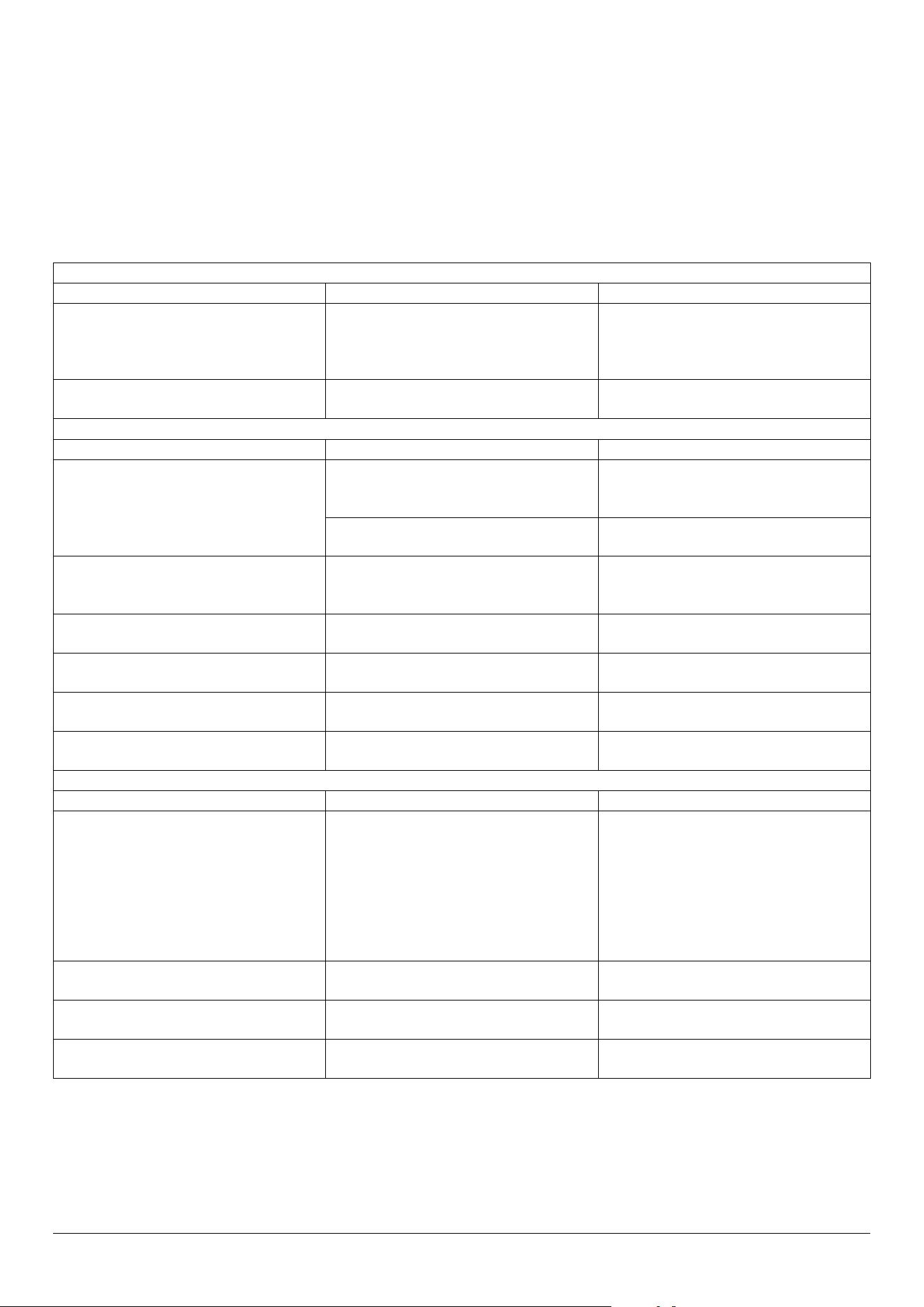
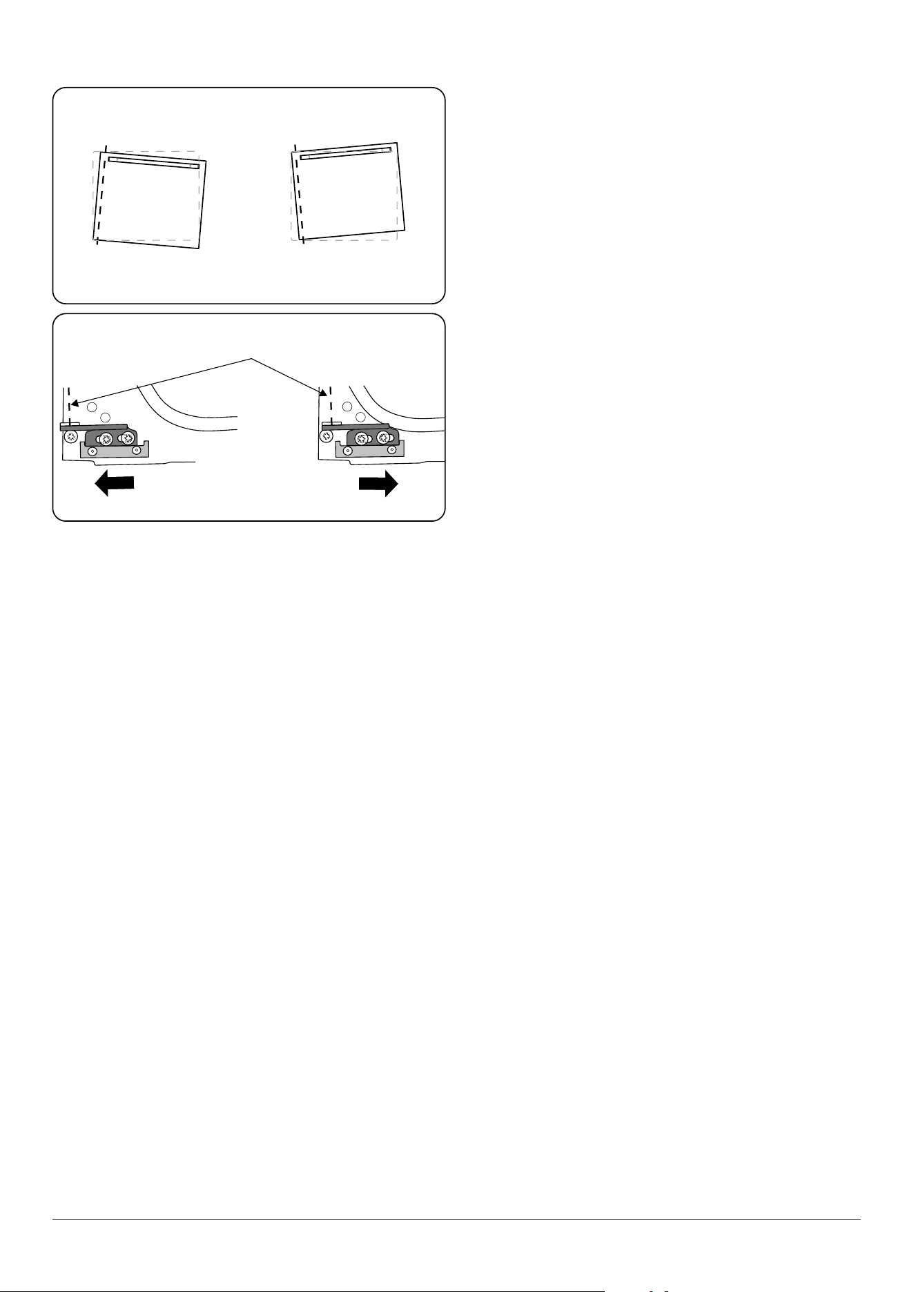
The door is misaligned
The bottom hinge of either oven door can be adjusted to
alter the angle of the door (Fig. 7.1). Loosen the bottom
hinge xing screws and use the notch and a at bladed
screwdriver to move the position of the hinge to set the
hinge position (Fig. 7.2).
ArtNo.320-0006b -Mercury oven door hinge adjustment
Eect of hinge adjustment – exaggerated for clarity
ArtNo.320-0007 Oven door hinge adjustment 2
Centreline of hinge pin
Oven door omitted for clarity
Fig. 7.1
Fig. 7.2
21
8. Installation Instructions
DO NOT store or use gasoline or other ammable vapors and liquids in the vicinity
of this or any other appliance.
WHAT TO DO IF YOU SMELL GAS
DO NOT try to light any appliance.
DO NOT touch any electrical switch.
DO NOT use any phone in your building.
Immediately call your gas supplier from a neighbor’s phone. Follow the gas
supplier’s instructions.
If you cannot reach your gas supplier, call the re department.
Installation and service must be performed by a qualied installer, service agency
or the gas supplier.
WARNING!
If the information in these instructions is not followed exactly, a re or
explosion may result, causing property damage, personal injury or death.
WARNING!
The anti-tip device supplied with this range must be installed when the appliance is installed. This will reduce the risk of
tipping of the appliance from abnormal usage or by excessive loading of the oven door.
ArtNo.030-0030 - RM tipping
warning symbols
WARNING!
• ALL RANGES CAN TIP. A CHILD OR ADULT CAN TIP THE RANGE AND BE KILLED.
• INSTALL ANTI-TIP BRACKET PACKED WITH RANGE - SEE INSTALLATION
INSTRUCTIONS.
• A CHILD OR ADULT CAN TIP THE RANGE AND BE KILLED
• ENGAGE THE RANGE TO THE ANTI-TIP DEVICE - SEE INSTALLATION
INSTRUCTIONS.
• RE-ENGAGE THE ANTI-TIP DEVICE IF THE RANGE IS MOVED.
• FAILURE TO DO SO CAN RESULT IN DEATH OR SERIOUS BURNS TO
CHILDREN OR ADULTS.

22
Meaning / Description Symbol
WARNING / CAUTION
An appropriate safety instruction
should be followed or caution taken if
a potential hazard exists.
!
DANGEROUS VOLTAGE
To indicate hazards arising from
dangerous voltages.
PROTECTIVE EARTH (GROUND)
To identify any terminal which
is intended for connection to an
external conductor for protection
against electric shock in case of a
fault, or the terminal of a protective
earth (ground) electrode.
Meaning / Description Symbol
HEAVY
This product is heavy and reference
should be made to the safety
instructions for provisions of lifting
and moving.
DISCONNECT MAINS SUPPLY
Disconnect incoming supply before
inspection or maintenance.
The following symbols are related to safety and are used on the product and throughout this manual.
INSTALLATION
Check the appliance is electrically safe when you have nished.
23
Firstly, please complete the appliance details below and keep them safe for future reference – this information will enable us
to accurately identify the particular appliance and help us to help you. Filling this in now will save time and inconvenience
if you later have a problem with the appliance. It may also be of benet to keep your purchase receipt with this leaet. You
may be required to produce the receipt to validate a warranty eld visit.
* This information is on the appliance data badge.
If you have a problem
In the unlikely event that you have a problem with your appliance, please refer to the rest of this booklet, especially the
problem solving section, rst to check that you are using the appliance correctly .
If you are still having diculty, please contact Tech Support at 800.914.4799 or email techsupp@middlebyresidential.com .
Please note
For warranty information or to register your AGA range, email customersupport@middlebyresidential.com. You may also
refer to the warranty document provided with the appliance or contact 888.845.4641 Option 3 .
Out of warranty
We recommend that our appliances are serviced regularly throughout their life to maintain the best performance and
eciency. The frequency of service will depend on usage – for normal usage once a year should suce. Service work should
only be carried out by a suitably Authorized Person .
Spare parts
To maintain optimum and safe performance, we recommend that only genuine spare parts are used. DO NOT use re-
conditioned or unauthorized controls. Contact 888.845.4641 Option 1 or email parts@middlebyresidential.com .
Dealer’s Name and Address
Name of Appliance
Appliance Serial Number*
Fuel Type
Date of Purchase
Installer’s Name, Address and
Telephone No.
Date of Installation
9. Service and parts
INSTALLATION
Check the appliance is electrically safe when you have nished.
24
Regulations
Installation of this range must conform with local
codes, or in the absence of local codes, with the
National Fuel Gas Code, ANSI Z223.1/NFPA.54, latest
edition.
In Canada, installation must conform with the
current Natural Gas Installation Code, CAN/
CGA-B149. 1 or the current Propane Installation
Code, CAN/CGA-B149.2, and with local codes where
applicable.
In Canada, electrical grounding must be in
accordance with the current CSA C22.1 Canadian
Electrical Code Part 1 and/or local codes. See
‘Electrical Connection’ in this section.
CSA 1.1, latest edition and CAN/CGA-22.2 latest edition.
This range becomes hot in use, the cooktop burners produce
exhaust gases.
IMPORTANT
Observe all governing codes and ordinances.
The range must be properly grounded.
This appliance is heavy. Ensure you have the correct
facilities to complete the move. To nd the weight of
the appliance, refer to the "Technical data".
Refer to "Positioning the range".
Save these instructions for the local electrical
inspector’s use.
For your safety
DO NOT store or use combustible materials, gasoline or other
ammable vapors and liquids in the vicinity of this or any
other appliance.
If you smell gas,
• open windows.
• DO NOT touch electrical switches.
• Extinguish any open flame.
• Immediately call your gas supplier.
Improper installation, adjustment, alteration,
service or maintenance can cause injury or property
damage. Refer to this manual. For assistance or
additional information, consult a qualied engineer.
NEVER reuse old exible connectors. The use of old
exible connectors can cause gas leaks and personal
injury. Always use NEW exible connectors when
installing a gas appliance.
IMPORTANT!
• Remove all packing material and literature from oven
before connecting gas and electrical supply to range.
• Have your range installed by a qualified installer.
• DO NOT install your range on a substrate that cannot
withstand 180 °F (82 °C).
• DO NOT install your range directly onto carpeting.
Ensure an appropriate, non-combustible, substrate is
installed prior to installing the range.
• Make sure the wall coverings around the range can
withstand heat generated by the range up to 200 °F
(93 °C).
• There must be a gap of at least 30’’ (762 mm) between
the top of the range and any combustible surface above
it.
• If a ventilating hood is installed above the range follow
the installation instructions supplied with the hood.
This type of ventilation system may cause ignition
and combustion problems with the gas cooking
appliance, resulting in personal injury or unintended
operation. Ventilating systems that direct the air
upwards can be used.
Items of interest to children should not be stored
above a range – children climbing on the range to
reach items could be seriously injured.
10. Installation safety instructions

INSTALLATION
Check the appliance is electrically safe when you have nished.
25
Converting to propane gas
This appliance is supplied set for natural gas.
A conversion kit for Propane gas is supplied with the range
(A060048).
The conversion must be performed by a qualied LP gas
installer.
For installation 5000 ft above sea level, the
appliance must be converted using high altitude kit
A065744. Contact your distributor.
Location of the range
The range may be installed in a kitchen/kitchen dining area
but NOT in a room containing a bath or shower.
The range is freestanding and should not be placed on a
separate base.
DO NOT locate the range where it may be subject to strong
drafts. Any openings beneath the range or behind the range
should be sealed.
The range should be positioned on a solid substrate.
Your range is heavy DO NOT place on soft oor
coverings, such as cushioned vinyl or carpeting.
Use care when moving the range on cushioned vinyl or
carpeted ooring.
When the oor covering ends at the front of the range, the
area that the range will rest on should be built up to the same
level or higher than the oor covering.
Also, make sure your oor covering will withstand
180°F. (See the Installation Safety Instructions
section).
(See the Installation Safety Instructions section).
INSTALLATION
Check the appliance is electrically safe when you have nished.
26
You will need the following equipment to complete the range
installation satisfactorily:
• Multimeter (for electrical checks).
• Allen keys (provided in pack).
You will also need the following tools:
1. Steel tape measure
2. Cross-head screwdriver
3. Flat head screwdriver
4. Spirit level
5. 9/16 " (13 mm) wrench or socket wrench
6. 5/16 " (8 mm) socket wrench or ring wrench
Additional materials you may need:
1. Gas line shut-o valve.
2. Pipe joint sealant or UL-approved pipe thread tape with
Teon* that resists action of natural and LP gases.
3. Flexible metal appliance connector (½’’ I.D.). A 5foot
length is recommended for ease of installation
but other lengths are acceptable. Never use an old
connector when installing a new range.
4. Flare union adapter for connection to gas supply line
(¾’’ or ½’’ NPT x ½’’ I.D.).
5. Flare union adapter for connection to pressure regulator
on range (½’’ NPT x ½’’ I.D.).
6. To protect any oor covering under the range a sheet of
¼’’ thick plywood or equivalent large enough to stand
the range on.
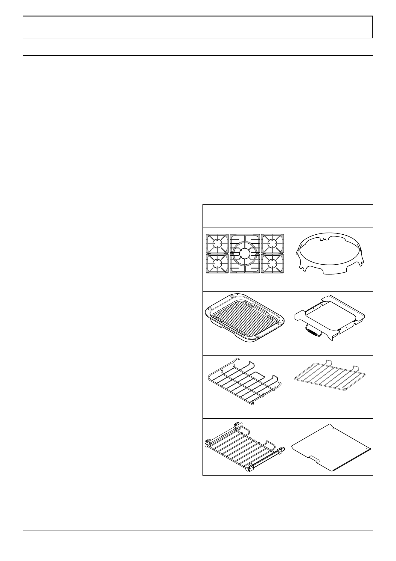
Included Accessories:
6 interlocking cast iron grates Wok Cradle
Broiler pan & trivet Broiler pan cradle
1 drop shelf 2 at shelves
2 telescopic shelves 2 Oven Base Trays
11. Installation
INSTALLATION
Check the appliance is electrically safe when you have nished.
27
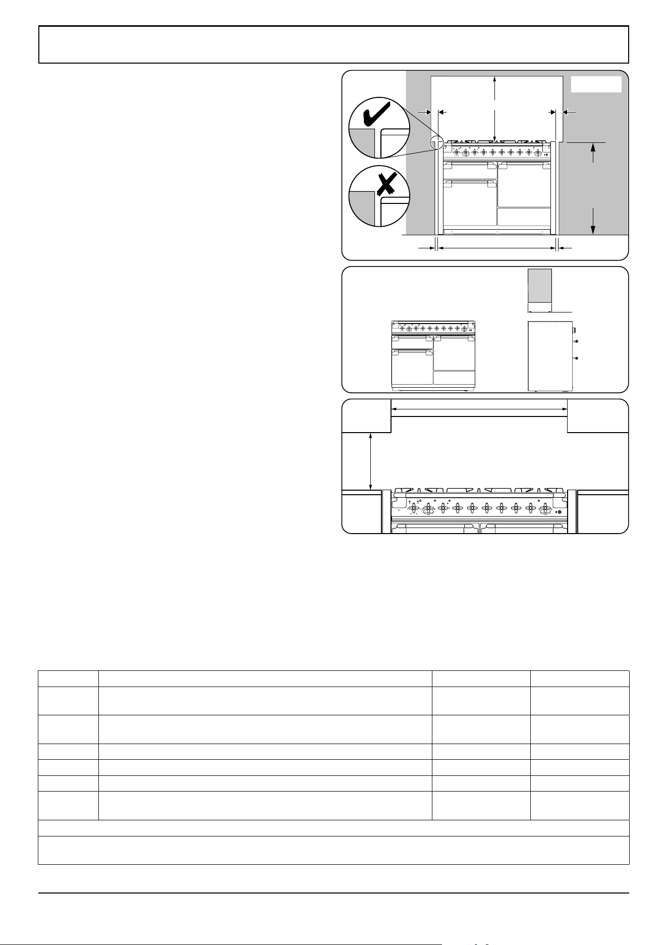
Positioning the range
Fig. 11.1, Fig. 11.2 and Fig. 11.3 show the minimum
recommended distance from the range to nearby
combustible surfaces (see Table 11.1).
We recommend a gap of no more than 3/16” (5 mm) (see Table
11.1) either side of the appliance for moving the range. It
must be possible to move the range in and out for cleaning
and servicing.
Above hotplate surround should be level with, or above, any
adjacent work surface (Fig. 11.1).
*Any rangehood should be installed in accordance with the
hood manufacturer’s instructions.
**Any splashback must be tted in accordance with the
manufacturer’s instructions. Allowance should be made for
the additional height of the ue trim, which is tted to the
rangetop.
Surfaces of furniture and walls at the sides and rear of the
appliance should be heat, splash and steam resistant. Certain
types of vinyl or laminate kitchen furniture are particularly
prone to heat damage and discoloration.
We cannot accept responsibility for damage caused by
normal use of the range to any material that de-laminates or
discolors at temperatures less than 149°F/65°C above room
temperature.
ArtNo.110-0040 - 110 Mercury min spacings
0
100
140
180
0
1
2
33
2
1
2
20
0 0
0 0
0
0
0
100
1
40
18
0
220
0
(1208 mm)
47
9
/
16
“
36
7
⁄
32
” (920 mm) min
37
13
⁄
64
” (945 mm) max
A
BB
A
C
0
100
140
180
0
1
2
33
2
1
220
0 0
0 0
0
0
0
100
140
180
220
0
D
2
0
1
00
140
180
0
1
2
33
2
1
220
0 0
0 0
0
0
0
1
00
140
180
220
0
F
E
**
Fig. 11.1
Fig. 11.2
Fig. 11.3
Dimension Description USA Canada
A
Gap between side of appliance and adjacent vertical surface ABOVE cooktop level
1 3/16" (30 mm) 1
1 3/16" (30 mm) 1
B
Gap between side of appliance and adjacent vertical surface BELOW cooktop level
3/16" (5 mm)
½" (12 mm)
C
Gap between cooktop level and any horizontal combustible surface
31 ½" (800 mm) 2
31 ½" (800 mm) 2
D
Maximum depth of cabinets installed above the top surface cooking sections 13" (330 mm) 13" (330 mm)
E
Minimum distance between horizontal surfaces less than dimension C
47 9/16" (1208 mm)
47 9/16" (1208 mm)
F
Minmum distance between horizontal cabinets and worktop surfaces adjacent to range
16 5/32" (410 mm) 16 5/32" (410 mm)
1. For non-combustible surfaces (such as unpainted metal or ceramic tiles) this gap is not required
2. This dimension can be reduced to 24" (610 mm) if the bottom of the wooden or painted metal cabinet is preserved with a non-combustible material
Table 11.1
Clearances to combustibles
INSTALLATION
Check the appliance is electrically safe when you have nished.
28
26
1
/
8
(663 mm)
27
3
/
8
(695 mm)
28
7
/
16
(723 mm)
46
5
/
16
(1177 mm)
3
1
/
2
”
(90 mm) min
3
1
/
2
”
(90 mm) min
Fig. 11.5
Fig. 11.6
Fig. 11.4
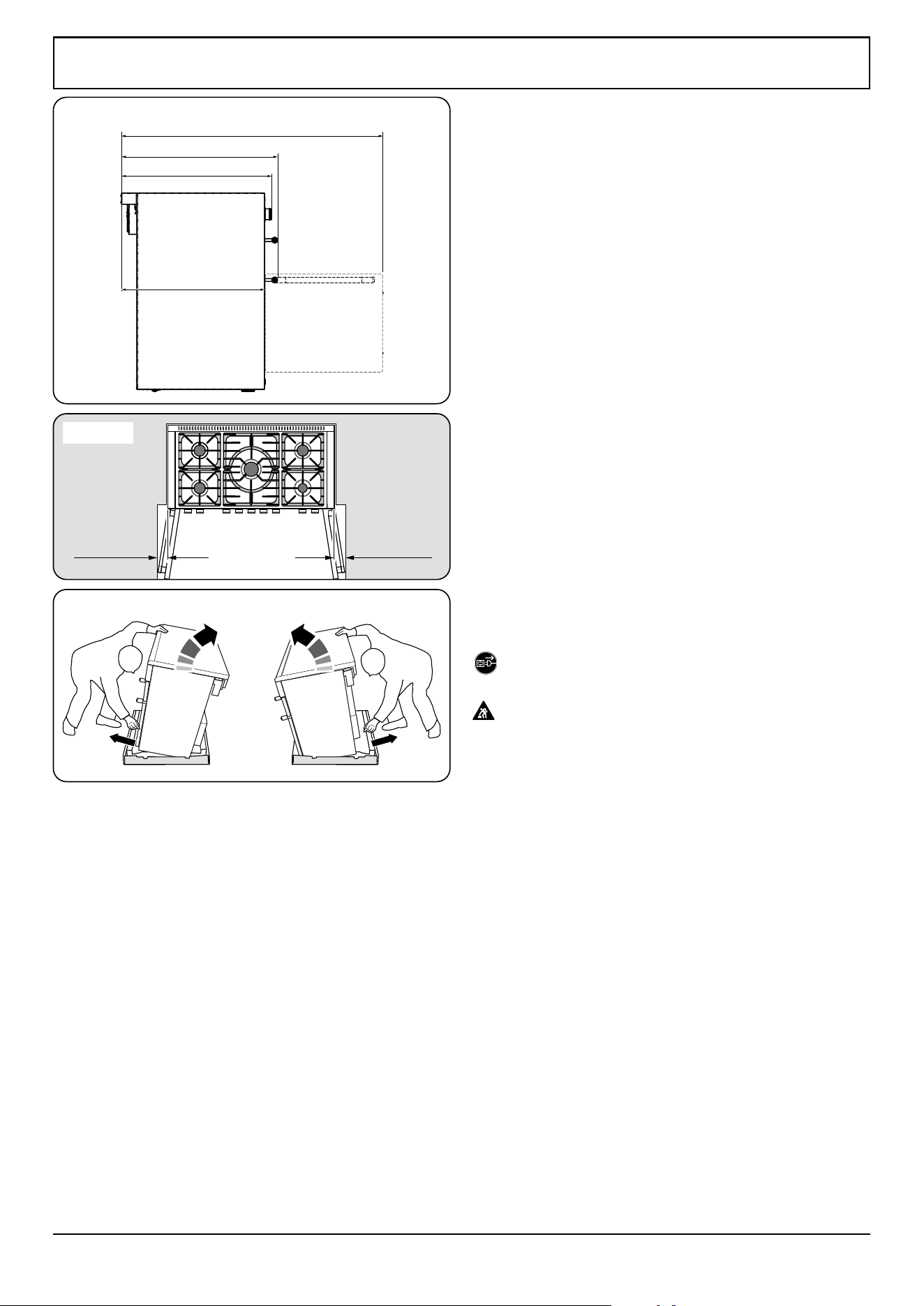
The depth of the range is 28
7
/16 " (723 mm) overall (Fig. 11.4).
If the range is near a corner of the kitchen, a clearance of 3 ½”
(90 mm) is required to allow the oven doors to open
(Fig. 11.5). The actual opening of the doors is slightly less but
this allows for some protection of your hand as you open the
door.
When fitting between kitchen
cabinets
We recommend a gap of 48” (1218 mm) between units to
allow for moving the range. DO NOT box the range in – it
must be possible to move the range in and out for cleaning
and servicing.
In the USA leave a gap of at least 1/5” (5 mm) on either
side of the range (a 48” (1218 mm) gap between
units). The range should be positioned centrally.
For Canada leave a gap of at least ½” (12 mm) on
either side of the range (a 48 ½” (1232 mm) gap
between units). The range should be positioned
centrally.
We also recommend that you DO NOT nal x any adjacent
cabinets until the range is installed. Decorative mouldings or
handles on cabinet doors and fronts may interfere with the
opening of the oven doors.
Moving the range
On no account try and move the range while it is
plugged into the electricity supply.
This appliance is heavy. Ensure you have the correct
facilities to complete the move. To nd the weight of
the appliance refer to the "Technical data".
We recommend that two people manoeuvre the range. Make
sure that the oor covering is rmly xed, or removed, to
prevent it being disturbed when moving the range around.
To help you, there are two levelling rollers at the back, and
two screw-down levelling feet at the front.
Remove the polystyrene base pack. From the front, tilt the
range forward and remove the front half of the polystyrene
base (Fig. 11.6). Repeat from the back and remove the rear
half of the polystyrene base. Also remove the cardboard base
tray.
29
INSTALLATION
Check the appliance is electrically safe when you have nished.
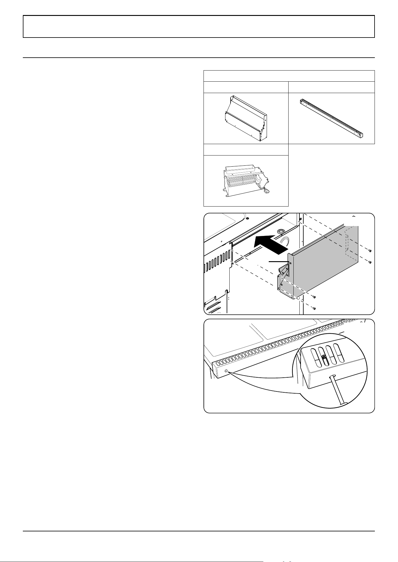
Checking the parts:
Flue Flue Vent
Fan Assembly
Fitting the flue
1. Remove the four screws from the broiler ue opening
(Fig. 12.1).
2. Present the removable ue up to broiler ue opening.
Make sure that the bottom ange of the removable ue
ts inside the xed ue, secure in place with the four
screws (Fig. 12.1).
Fitting the flue vent
1. Loosen the three nuts and bolts in the back of the
hotplate (Fig. 12.2).
2. Fit the ue vent over the bolts and slide down (Fig.
12.2). Tighten the nuts to secure.
12. Fitting the flue, flue vent and side panels
Fig. 12.1
Fig. 12.2
Flue
30
INSTALLATION
Check the appliance is electrically safe when you have nished.
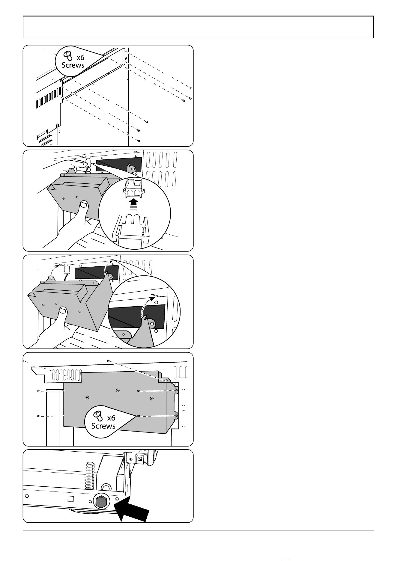
Fitting the cooling fan box
1. Remove the six screws where the cooling fan box will be
xed Fig. 12.3.
2. The shape of the molex plug should match the socket.
Gently connect the molex plug to the molex connector
socket Fig. 12.4.
3. The cooling fan has two tabs which connects to the
slots underneath the ue vent. Gently align the cooling
fan box tabs to the slots underneath the ue vent Fig.
12.5.
4. Replace the six screws Fig. 12.6.
Before tting the side panels, it is recommended
that the required height of the range is set. This will
simplify the Side Panels tting procedure.
Setting the height
You are recommended to use a spirit level on the
hotplate to check the range is level.
The front feet and rear rollers can be adjusted to level the
range (Fig. 12.7).
1. To adjust the height of the rear of the range, t a 13 mm
spanner or socket wrench onto the hexagonal adjusting
nut.
2. Rotate the nut – clockwise to raise – counter-clockwise
to lower. Make sure to lower BOTH REAR ROLLERS.
3. To set the front turn the feet bases to raise or lower.
Fig. 12.3
Fig. 12.4
Fig. 12.5
Fig. 12.6
Fig. 12.7
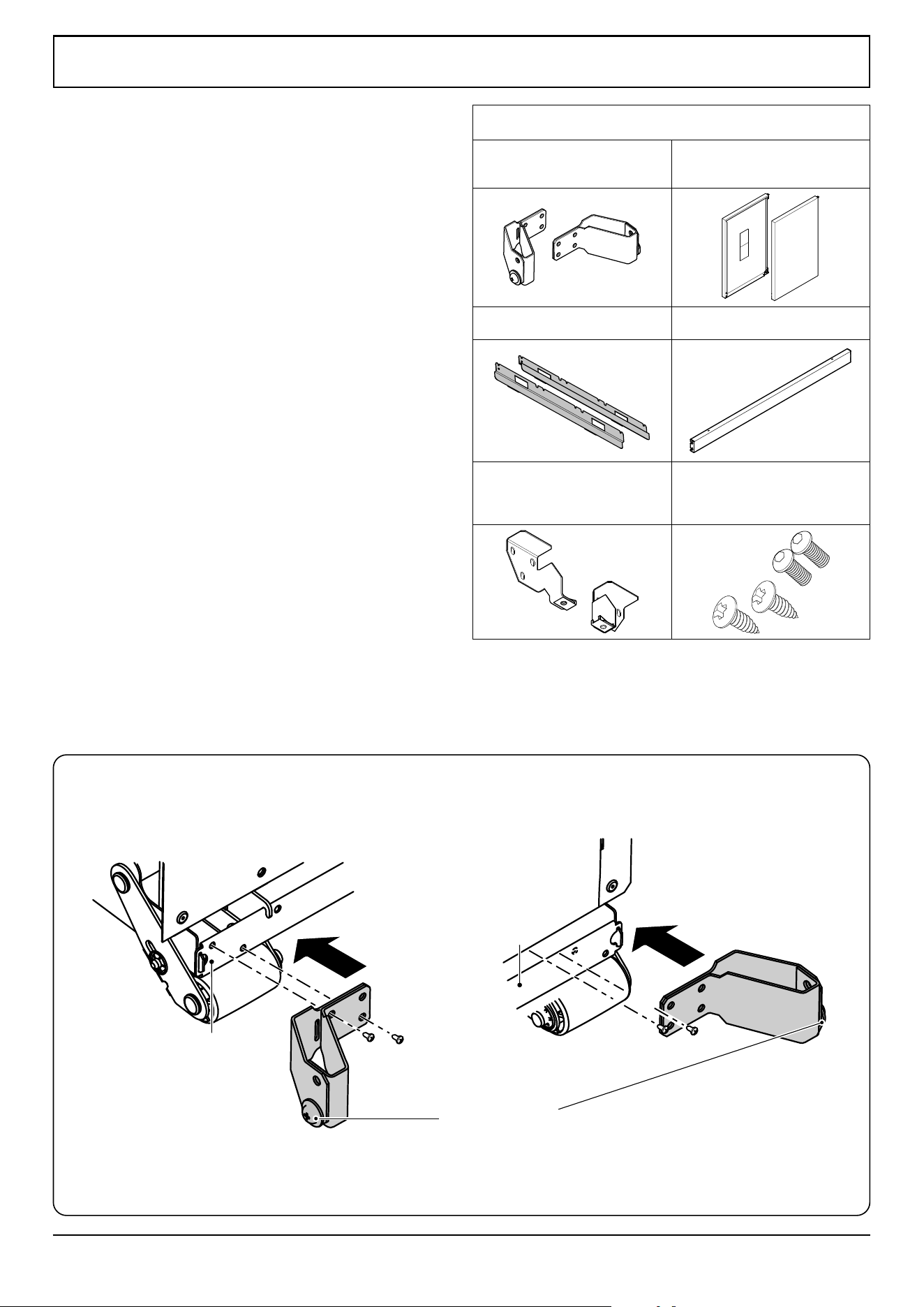
31
INSTALLATION
Check the appliance is electrically safe when you have nished.
Checking the parts:
Side panel rear retaining brackets
A052064 - Right-hand
A052067 - Left-hand
Side panels
A051761 - Right-hand
A051759 - Left-hand
Obscuring Trim Side Panel x2
Q050718
Bottom Panel (Toe kick)
Bottom Panel (Toe kick)
Front Mounting Brackets
Q050877 - Left-hand
Q050878 - Right-hand
Screws supplied
2x Machine Screw
2x Self-Tapping Screw
Fitting the side panel rear
retaining brackets
1. Located at the bottom left and right rear corner of the
range, remove the two screws (Fig. 12.8).
2. Fit the left and right retaining brackets to the base
frame and ret and tighten the screws (Fig. 12.8).
Rear left Rear right
Note the position
of locating washer
Base Frame
Base Frame
Fig. 12.8
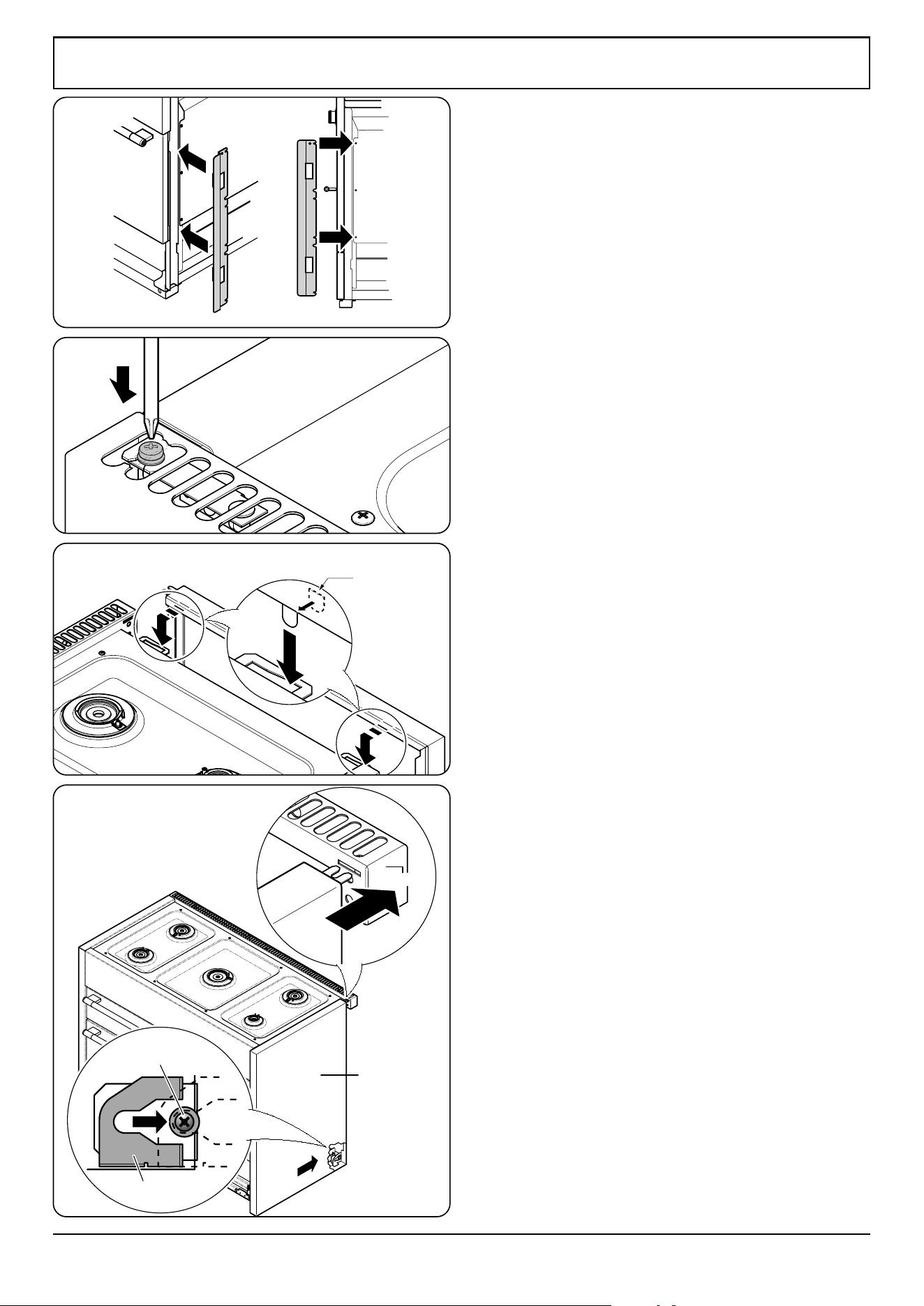
32
INSTALLATION
Check the appliance is electrically safe when you have nished.
bk
Connect tab into
side bracket
Gasket
Flue Vent
Side panel bracket
Side Panel
Nylon Retaining
washer
Fig. 12.9
Fitting the obscuring trims
1. Located near the front on each side of the range there
are three screws. Loosen the top and bottom screws
(Fig. 12.9).
2. Slide the trim onto the screws and tighten to secure.
Fitting the side panels
1. Loosen the screw in the ue vent (Fig. 12.10).
2. Inside the top of the side panel top are two tabs. Attach
the self adhesive gaskets to each tab and connect these
tabs into the cut-outs in the top edge of the range
(Fig. 12.11).
3. Slide the side panel back so that the side panel bracket
in the base connects to the rear retaining washer and
the slotted tab at the top rear connects onto the screw
in the ue vent (Fig. 12.12).
4. Check everything is rmly connected and tighten
the screw in the ue vent to secure the side panel in
position (Fig. 12.10).
NOTE: The bottom front of the side panels will be loose.
These are secured once the bottom panel (toe kick) is tted.
NOTE: If a side panel is loose, t one of the extra gaskets to
the inner face of the front bracket locating tabs and ret.
Fig. 12.10
Fig. 12.11
Fig. 12.12
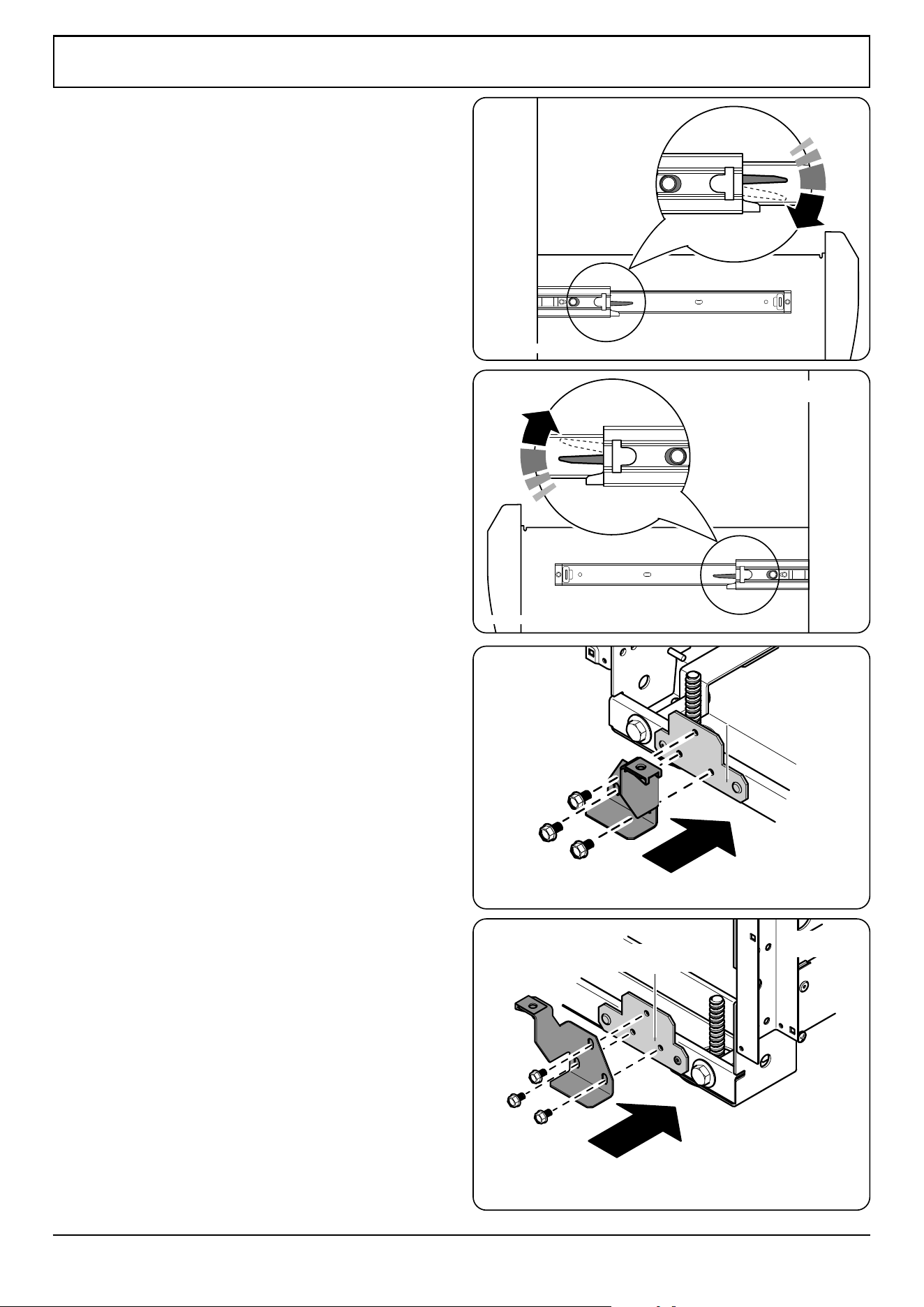
33
INSTALLATION
Check the appliance is electrically safe when you have nished.
Left Mounting
Plate
Front Left
Right Mounting
Plate
Front right
Fitting the front mounting
brackets
1. Open the right-hand oven door and pull the drawer out
to its furthest point.
2. Push the ends of the plastic clips (Fig. 12.13 and Fig.
12.14) to release the catches holding the drawer to the
side runners. At the same time pull the drawer forward
and away from the side runners.
For safety’s sake make sure the drawer runners are
out of the way.
3. On the front of the range base there are two mounting
plates. Remove the three xing screws from each plate
(Fig. 12.15).
4. Fit the left and right-hand front mounting brackets as
shown in (Fig. 12.15 and Fig. 12.16). DO NOT fully
tighten the mounting screws at this stage.
Fig. 12.13
Fig. 12.14
Fig. 12.15
Fig. 12.16
Down on the left-hand side.
Up on the right-hand side
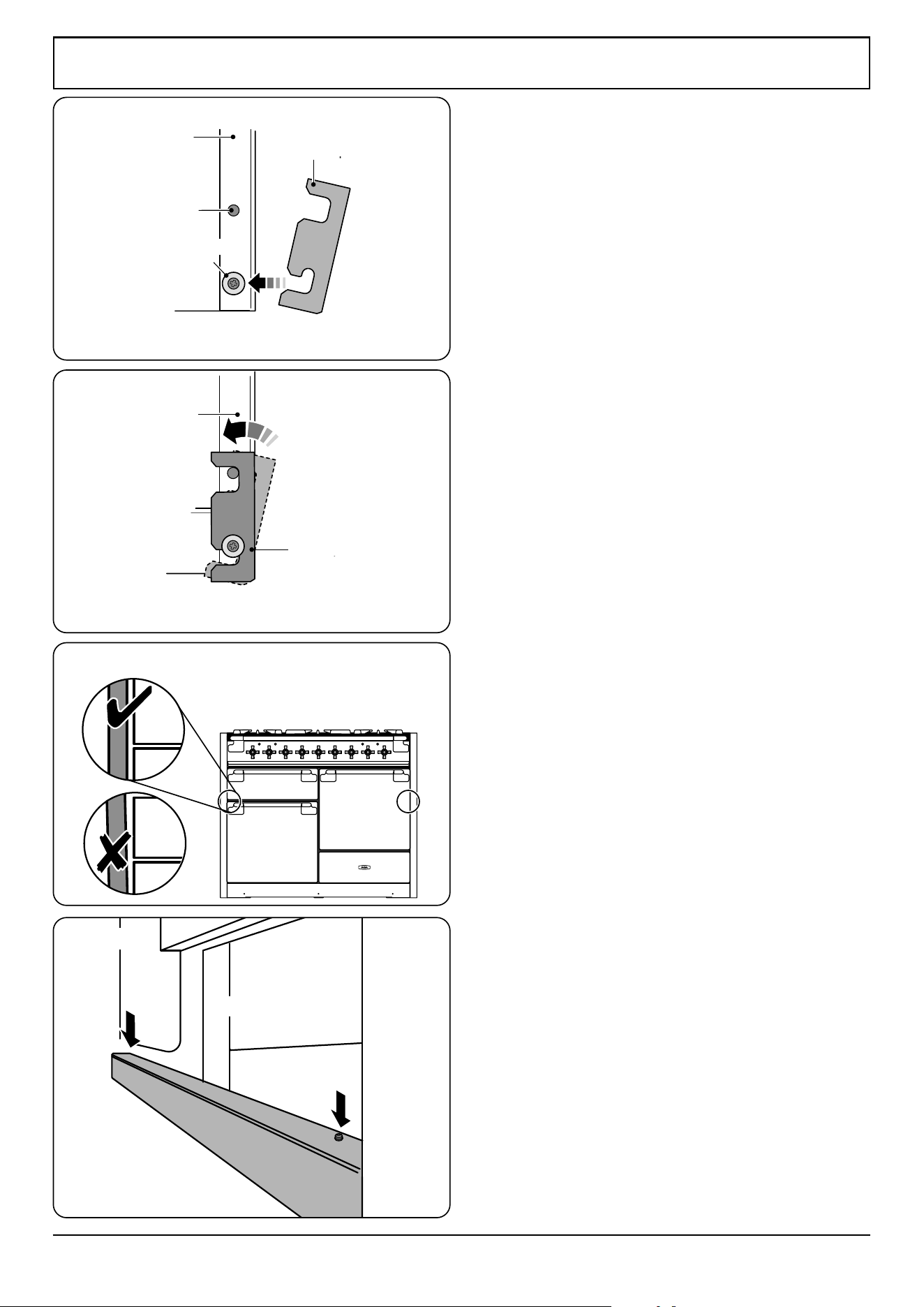
34
INSTALLATION
Check the appliance is electrically safe when you have nished.
Nylon Locating
washer
Bottom panel
Pin
Side view of the front base
Side panel
Bottom panel
Side view of the front base
Side panel
Fitting the bottom panel (toe kick)
1. Tilt the bottom of the panel slightly to locate the lower
slots onto the washers (Fig. 12.17). Now rotate the
panel to t over the pins (Fig. 12.18).
2. Using the two screws and allen key supplied, loosely
t the bottom panel onto the mounting brackets (Fig.
12.20). DO NOT tighten at this stage.
3. Adjust the bottom panel to set the gap between the
side panels and doors equally (Fig. 12.19). When it is
positioned correctly, use a suitable at open-ended
spanner to tighten the bracket screws, and then tighten
the bottom panel screws (Fig. 12.20) with the allen key
provided.
Fig. 12.17
Fig. 12.18
Fig. 12.19
Fig. 12.20
Toe kick
Toe kick
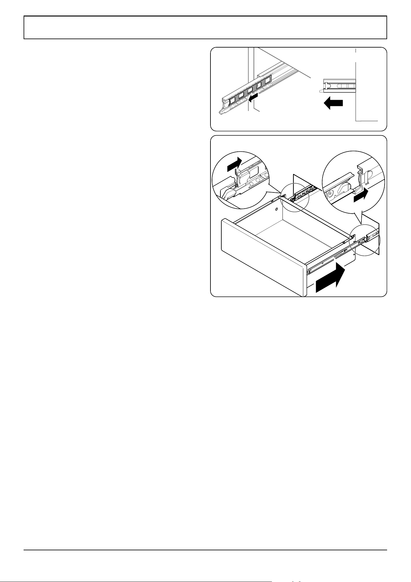
35
INSTALLATION
Check the appliance is electrically safe when you have nished.
Make sure the inner
rail is pulled forwards
Fitting the drawer
1. To t the drawer, pull the side rails fully out (Fig. 12.21).
2. Carefully move the drawer back between the rails and
rest it on the side rails.
3. At each side, hold the front of the drawer and pull the
side rail forward so that the clips click into position,
holding the drawer to the side rails (Fig. 12.22).
Fig. 12.21
Fig. 12.22
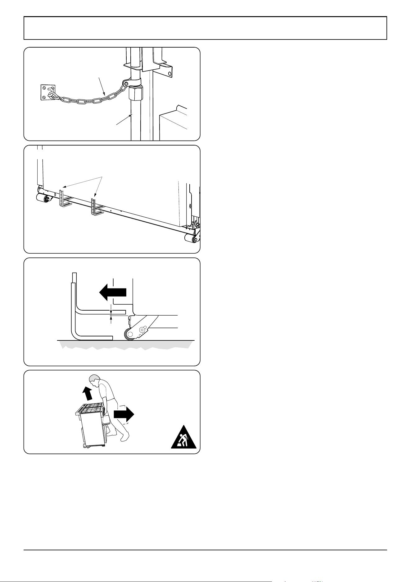
36
INSTALLATION
Check the appliance is electrically safe when you have nished.
ArtNo.010-0004 Moving the cooker
Restraint chain
Rigid pipe of the appliance
Alternative positions
for anti-tip device
ArtNo.070-0014 - Stability bracket - Wall fitting
Cooker
Stability bracket
Floor
3 mm min
Typical floor mounting
Fig. 12.23
Fitting the restraint chain and anti-
tip device
1. A range using a exible gas connector must be secured
with a suitable restraint chain and anti-tip device.
2. When tting the restraint chain it should be kept as
short as is practicable and xed rmly to the rigid pipe
at the top, right-hand, rear of the range; when viewed
from the front (Fig. 12.23).
DO NOT x the chain to the exible hose at the base
of the range.
3. A suitable anti-tip device is supplied and shown in
(Fig. 12.24).
4. When tting the anti-tip bracket (Fig. 12.24 and
Fig. 12.25), adjust the bracket to give the smallest
practicable clearance between the bracket and the
engagement slot in the rear of the range.
5. Fit the bracket so that it engages as far as possible over
the chassis of the range.
DO NOT operate the range before the appliance is
in its installed position and the anti-tip devices are
engaged.
If the appliance is moved ensure that the anti-tip
devices are re-engaged and the range has been
returned to its original installed position.
DO NOT step, lean or swing on the range doors
or drawer as this could tip the range and result in
serious injury or death.
Completing the move
1. Open the broiler door and right-hand oven door so that
you can get a good grip on the bottom of the fascia
panel as you move the range (Fig. 12.26).
2. Position the range close to its nal position.
3. Check that the anti-tip device is engaged before moving
the range into its nal, installed position.
4. Re-check that the appliance is level.
DO NOT use the door handles or control knobs to
manoeuvre the range.
0
1
/
8
" (3 mm) min
Fig. 12.24
Fig. 12.25
Range
Anti-Tip bracket
Fig. 12.26
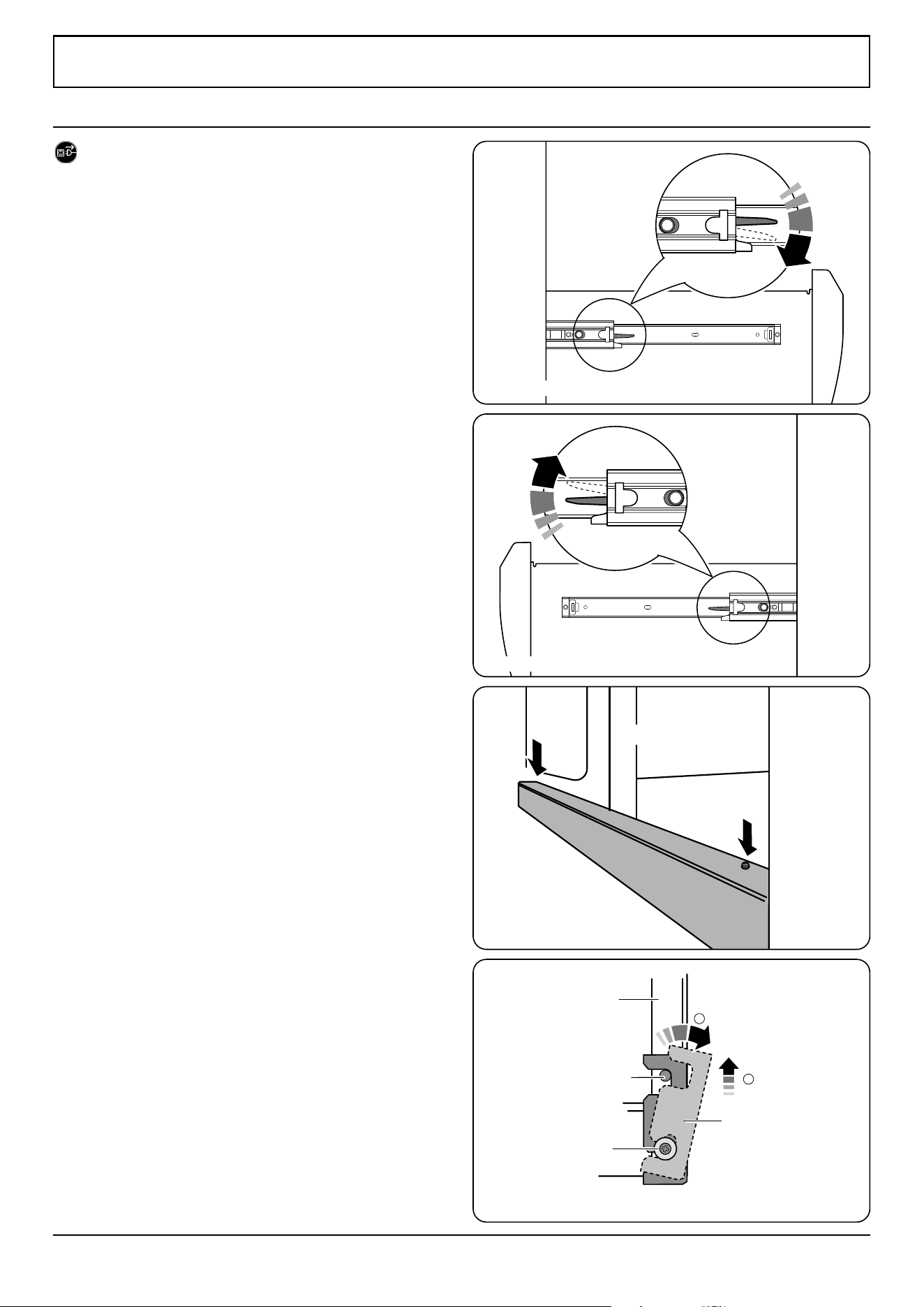
37
INSTALLATION
Check the appliance is electrically safe when you have nished.
Fig. 13.1
Fig. 13.2
13. Removing the side panels
DISCONNECT THE ELECTRICAL SUPPLY.
You will need the following equipment to remove the side
panels:
• Cross-head screwdriver
• Flat head screwdriver
• Allen keys (provided in pack).
Removing the storage drawer
1. Pull the drawer out to its furthest point.
2. Push the ends of the plastic clips (Fig. 13.1 and Fig.
13.2) to release the catches holding the drawer to the
side runners. At the same time pull the drawer forward
and away from the side runners.
For safety make sure the drawer runners are out of
the way.
Removing the bottom panel (toe kick)
1. After removing the drawer open the left-hand oven
door.
2. Unscrew the two allen head screws (Fig. 13.3), lift the
bottom panel up and slightly rotate the panel away
from the pins (Fig. 13.4).
Bottom panel
Side view at the front base of the cooker
Lift
1
Rotate
2
Pin
Locating
washer
Side panel
Down on the left-hand side.
Up on the right-hand side
Fig. 13.3
Fig. 13.4
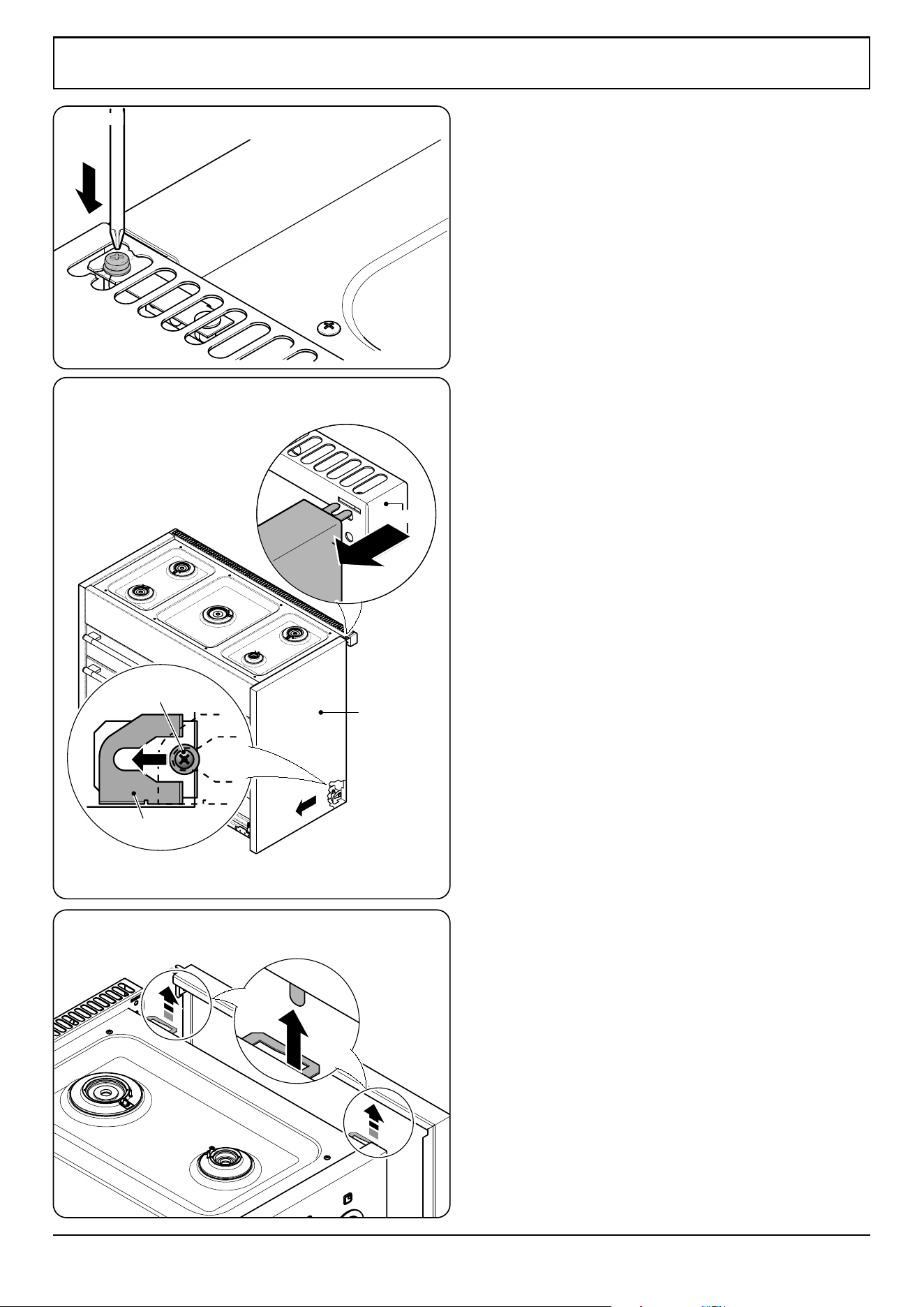
38
INSTALLATION
Check the appliance is electrically safe when you have nished.
Flue Vent
Side panel bracket
Side Panel
Nylon Retaining
washer
Removing the side panels
1. Loosen one screw in the vent (Fig. 13.5).
2. Push forward the side panel so that it moves away from
the ue vent and the retaining washer (Fig. 13.6).
3. Inside the top of the side panel top are two tabs. Move
the side panel up and away from the range (Fig. 13.7).
Fig. 13.5
Fig. 13.6
Fig. 13.7
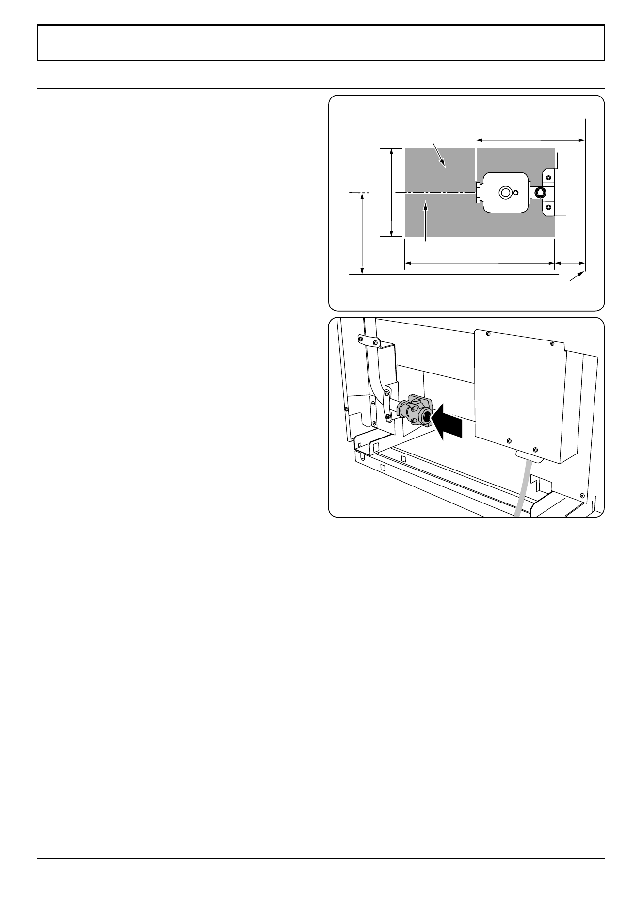
39
INSTALLATION
Check the appliance is electrically safe when you have nished.
7 ½”
5”
3 ½”
6 ¼”
11 ¼”
Gas inlet
Area accessible through drawer
Side of range
Gas shut off valve
Installation of this range must conform with local codes or, in
the absence of local codes, with the National Fuel Gas Code,
ANSI Z223.1-latest edition.
In Canada
The range must be installed in accordance with the current
CGA Standard CAN/CGA-B149 – Installation Codes for Gas
Burning Appliances and Equipment and/or local codes.
In The Commonwealth Of Massachusetts
This product must be installed by a licensed plumber or
gas tter when installed within the Commonwealth of
Massachusetts.
A “T” handle type manual gas valve must be installed in the
gas supply line to this appliance.
Gas supply requirements
Recommended gas pipe outlet locations are shown in
Fig. 14.1and Fig. 14.2.
Provide adequate gas supply
Prior to installation, make sure that the local distribution
conditions (nature of the gas and gas pressure) and the
adjustment of the appliance are compatible.
The range is designed to operate at a manifold pressure of 4’’
of water column (1 kPa) on natural gas. A conversion kit for
LP gas (Propane) is supplied with the range. When converted
to LP gas, a pressure of 10’’ of water column (2.49 kPa) is
required.
Make sure you are supplying your range with the correct type
of gas.
If the range is to be used on LP gas, a qualied LP installer
must convert it. We recommend that the range be converted
before installation. This must be done before the range can
be used on LP gas.
For proper operation, the pressure of natural gas supplied to
the regulator must be between 4½’’ and a maximum of 13’’ of
water column (1.12–3.24 kPa).
For LP gas, the pressure supplied must be between 10’’ and
13’’ of water column (2.49–3.24 kPa).
When checking for proper operation of the regulator, the
inlet pressure stated must be at least 1’’ wc (249 Pa) above the
manufacturer’s specied manifold pressure).
The pressure regulator located at the inlet of the range
manifold must remain in the supply line regardless of
whether natural or LP gas is being used.
A exible metal appliance connector used to connect the
range to the gas supply line should have an I.D. of ½’’ and be
5 feet in length for ease of installation.
Fig. 14.1
Fig. 14.2
14. Gas connection
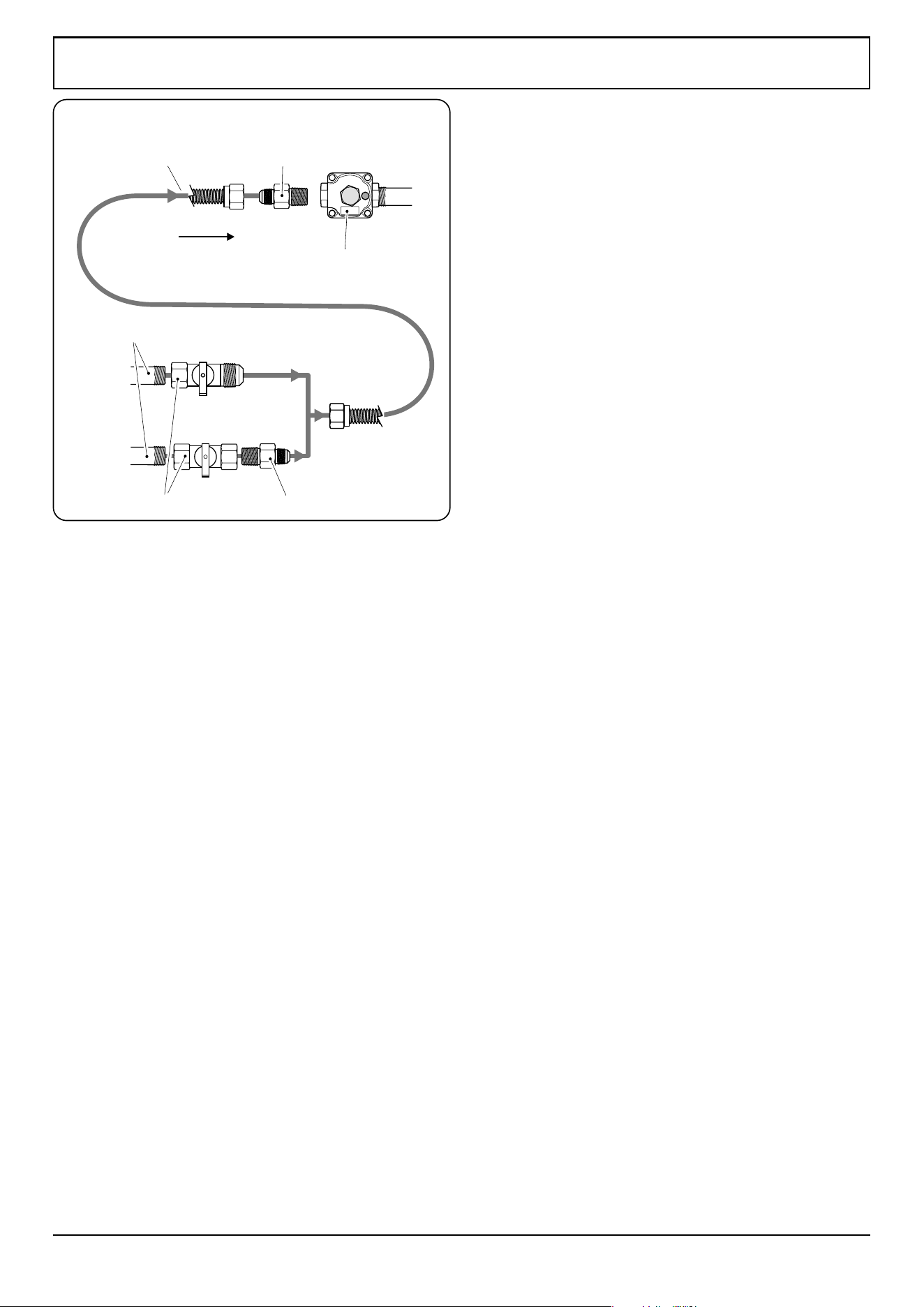
40
INSTALLATION
Check the appliance is electrically safe when you have nished.
ArtNo.280-0037 Gas Connection
½“ or ¾” gas pipe
Flexible connectorAdaptor
Appliance
gas inlet
Pressure regulator
AdaptorGas shut-off valve
Gas supply
OR
Connect the range to the gas supply
Shut o the main gas supply valve before disconnecting the
old range and leave it o until the new hookup has been
completed. Don’t forget to relight the pilot on other gas
appliances when you turn the gas back on.
Because hard piping restricts movement of the range, the
use of a CSA International-certied exible metal appliance
connector is recommended unless local codes require a hard-
piped connection.
The installation shall be made with a connector that complies
with ANSI Z21.69.CSA 6.16 and using a quick disconnect
device complying with ANSI Z21.41.CSA 6.9 (Fig. 14.3).
If disconnection of the restraint chain is necessary ensure the
restraint is reconnected when the appliance is returned to its
original installed position.
Never use an old connector when installing a new range.
If the hard piping method is used, you must carefully align
the pipe; the range cannot be moved after the connection is
made.
To prevent gas leaks, put pipe joint compound on, or wrap
pipe thread tape with Teon* around, all male (external) pipe
threads.
A. Install a manual gas line shut-o valve in the gas line in
an easily accessed location outside of the range. Make
sure everyone operating the range knows where and
how to shut o the gas supply to the range.
B. Install a male ½’’ are union adapter to the ½’’ NPT
internal thread elbow at inlet of regulator. Use a backup
wrench on the regulator tting to avoid damage. When
installing the range from the front, remove the 90°
elbow for easier installation.
C. Install male ½’’ or ¾’’ are union adapter to the NPT
internal thread of the manual shut-o valve, taking care
to backup the shut-o valve to keep it from turning.
D. Connect exible metal appliance connector to the
adapter on the range. Position the range to permit
connection at the shut-o valve.
E. When all connections have been made, make sure
all range controls are in the o position and turn on
the main gas supply valve. Use a liquid leak detector
at all joints and connections to check for leaks in the
system. Use a product specically manufactured for
leak detection. Leak testing of the appliance shall
be conducted in accordance to the manufacturer’s
instructions.
DO NOT use a ame to check for gas leaks.
* Teon: Registered trademark of DuPont
Fig. 14.3

41
INSTALLATION
Check the appliance is electrically safe when you have nished.
When using test pressures greater than ½ psi (3.5 kPa)
to pressure test the gas supply system of the residence,
disconnect the range and individual shut-o valve from the
gas supply piping.
The appliance must be isolated from the gas supply piping
system by closing its individual manual shut-o valve during
any pressure testing of the gas supply piping system at test
pressures equal to or less than ½ psi (3.5 kPa).

42
INSTALLATION
Check the appliance is electrically safe when you have nished.
Have your appliance properly installed and grounded by a
qualied technician. The installation must conform with local
codes or in the absence of local codes in accordance with the
National Fuel Gas Code, ANSI Z223.1/NFPA 54 or, in Canada,
the Natural Gas and Propane Installation Code, CSA B149.1
and in addition the National Electrical Code NFPA 70 or the
Canadian Electric Code, CSA C22.1.
Electrical requirements
For personal safety, DO NOT use an extension cord
with this appliance. Remove the house fuse or open
the circuit breaker before beginning installation.
WARNING Electrical Grounding Instructions.
This appliance is shipped with a (four-prong)
grounding plug for your protection against shock
hazard and should be plugged directly into a
properly grounded receptacle. DO NOT cut or
remove the grounding prong from this plug.
Prior to connecting the power cord to the wall
socket, inspect the cable for any damage that
may have occurred. In the event of damage please
consult your electrical installer.
Ensure that the power cord is routed so that it
cannot become damaged during the installation.
This appliance must be supplied with the proper voltage
and frequency, and connected to an individual, properly
grounded branch circuit, protected by a circuit breaker or
time-delay fuse, as noted on the rating plate.
Wiring must conform to National Electric Codes. If the electric
service provided does not meet the above specications,
have a licensed electrician install an approved outlet.
Because range terminals are not accessible after range is in
position, exible service conduit or cord must be used.
Provide proper electrical supply
This range must be supplied with 240 V 60 Hz, and connected to
an individual, properly grounded branch circuit protected by a
circuit breaker or time-delay fuse. If the electrical service provided
does not meet the above specications, it is recommended that a
licensed electrician install an approved outlet.
Connecting using the supplied cord and
plug
Your range is shipped with a 4-prong NEMA 14-50P plug to
be used in a NEMA 14-50R receptacle.
Your range is supplied with a ground link that can be
used when connecting to a three wire cord. Consult
your electrician before changing the supplied cord
kit.
15. Electrical connection
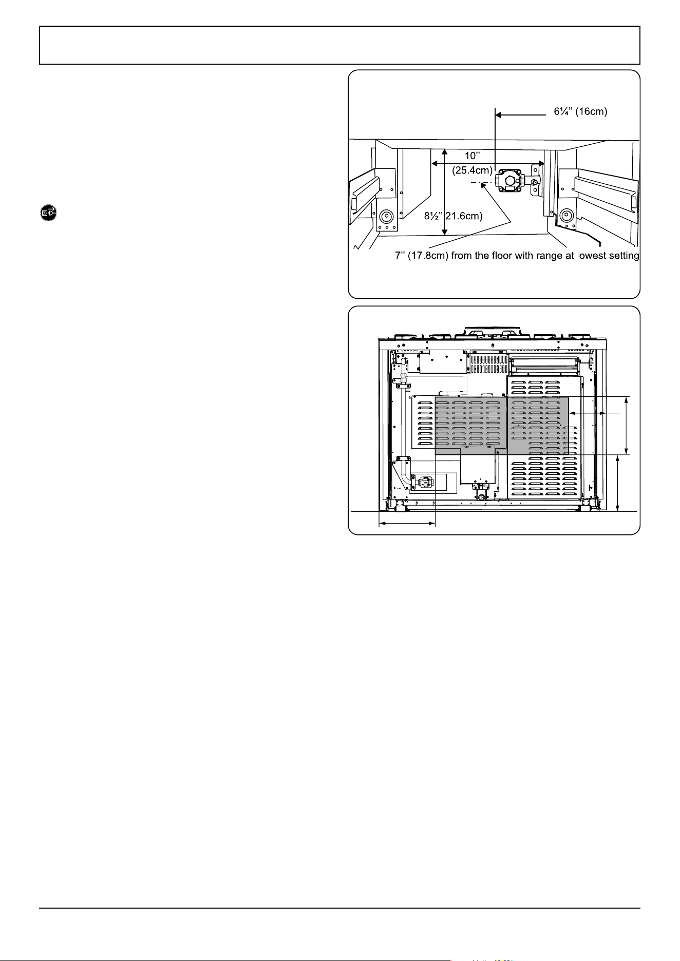
43
INSTALLATION
Check the appliance is electrically safe when you have nished.
Recommended electrical outlet location
When connecting using a NEMA 14-50R receptacle, if possible
position it so it can be accessed through the opening at the
rear of the drawer cavity (Fig. 15.1). Alternate location within
the shaded area in (Fig. 15.2). The distance between the back
of the range and the wall is approximately 4” (10.6 cm).
Plug the range power cord into a properly grounded wall
receptacle.
DISCONNECT THE ELECTRICAL SUPPLY.
8”
12”
12”
12”
Fig. 15.1
Opening inside the drawer cavity
Fig. 15.2
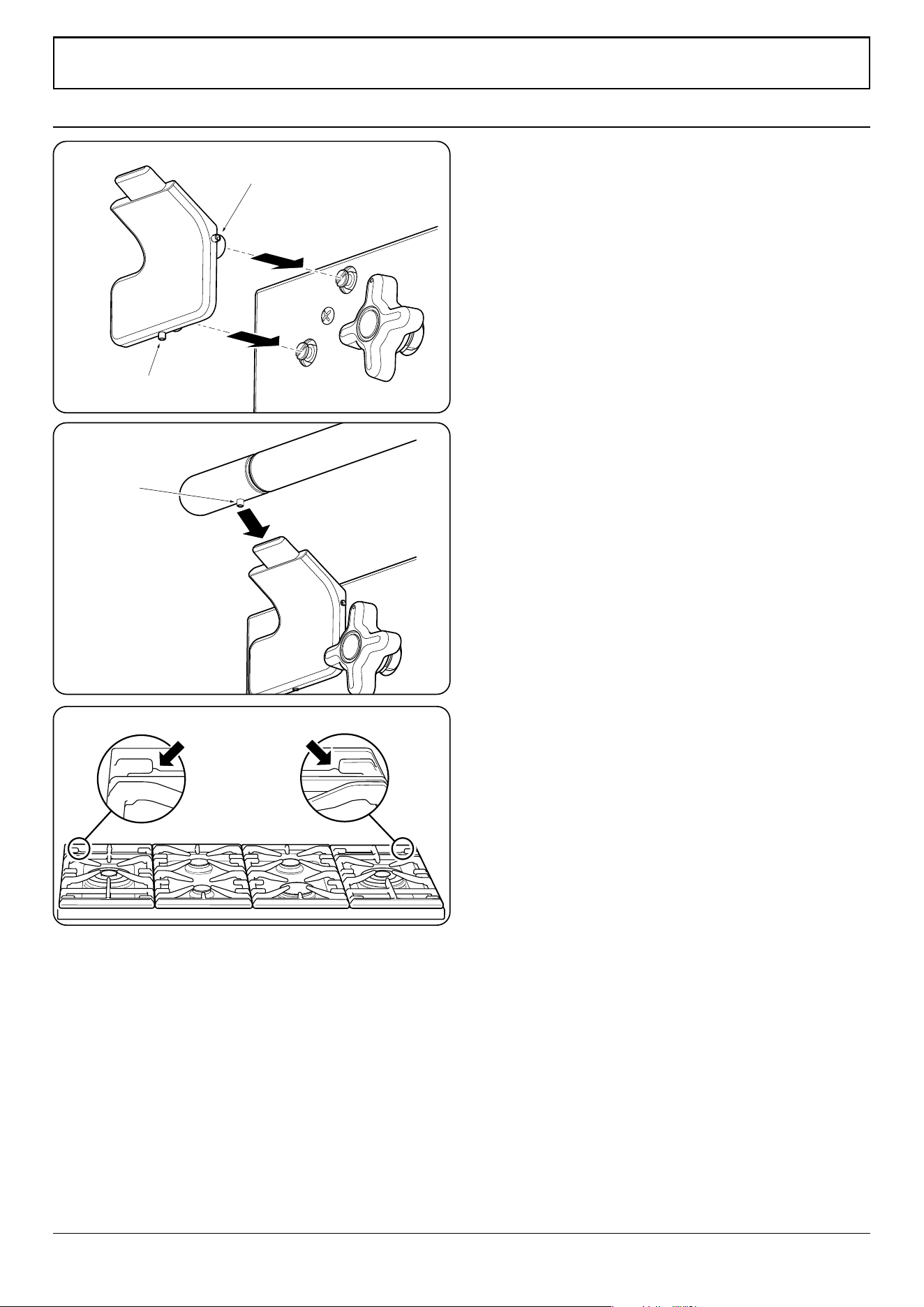
44
INSTALLATION
Check the appliance is electrically safe when you have nished.
Fitting the handrail
1. Using the 2 mm Allen key supplied, loosen the two
retaining screws in the base and side of the handrail
support. Fit the handrail support onto the locating
bosses on the fascia (Fig. 16.1).
NOTE: The handle support should face upwards.
2. Push the support back against the fascia and tighten the
oneretaining screws. Repeat for the other side. Check
that each support is secure.
3. Locate the handrail onto the support tabs and, using
the 3 mm Allen key supplied, tighten the one retaining
screws in the bottom to secure (Fig. 16.2).
Fitting the interlocking grates
Please note that the Continuous Grates supports are handed,
and may prevent the centre pan supports from tting
correctly. There is a small indent in the rear of each of the
outer supports. This indent should be towards the outer edge
of the range (Fig. 16.3).
Cooktop check
Refer to “Range Overview” and check operation of each
cooking zone in turn. Be sure to use pans of the correct size
and material.
Broiler check
Refer to “Range Overview” and check operation of the broiler
and that it heats up*.
Oven check
Refer to “Range Overview” and check the operation of both
ovens*. Check that the oven fans operate and the ovens heat
up.
* The cooling fan, located at the rear right hand side of the
cooktop, should operate with this function.
Customer care
Installer: Please complete your details in this guide, inform
the user how to operate the range and hand over the
instructions.
16. Final fitting and checks
Retaining screw
Retaining screw
Retaining
screw
Fig. 16.1
Fig. 16.2
Fig. 16.3
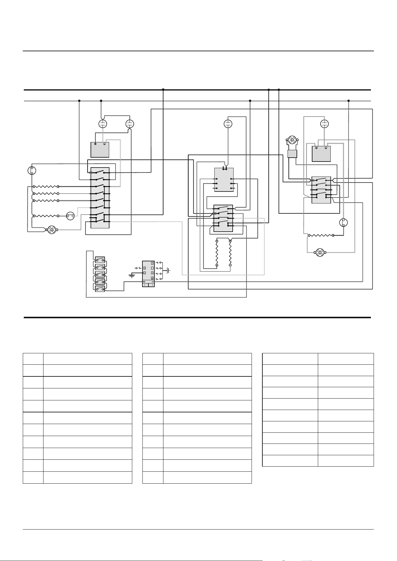
45
17. Circuit diagram
6
5
4
7
8
2
1
3
P2
P1
P3
P4
P5
P6
P7
P8
a
b
e
f
c
d
1
2
P028728
4
3
2
1
P4
P2
P1
P3
P033458
4
3
2
1
4
3
2
1
P4
P2
P1
P3
P033458
4
3
2
1
P1
42
4a P2
S2 S1
P029549
12
P026819
12
P026819
r
b
r
bk
gy
r
br
v
v
or
y
r
gy
y
r
bk
r
bk
v
v
v
br
br
br
or
b
bb
b
v
v
v
v
v
w
or
y
gy
w
or
v
br
br
br
br
brbr
br
br
r
or
w
y
v
w
w
v
r
r
r
r rr r
bk
r
bk
bk
gy
gy
gy
gy
or
or
or
bk
v
r
r
w
w
w
bk
bk
bk
r
r
r
r
r
gy
v
b
b
r
466
312
bk
v
5
F1
C3
C4
H
A3
A1
A2
C1
D2
D1
B2
B1
GG
GG
N
L2
L1
H
B3
B4
B5
B6
B7
H
C2
F2
Code Description
A1
Broiler Thermostat
A2
Broiler Controller
A3
Broiler Elements
B1
Left-hand oven thermostat
B2
Left-hand oven switch block
B3
Left-hand bottom element
B4
Left-hand oven top outer element
B5
Left-hand oven top inner element
B6
Left-hand oven fan element
B7
Left-hand oven fan motor
Code Description
C1
Right-hand oven thermostat
C2
Right-hand oven switch block
C3
Right-hand oven element
C4
Right-hand oven fan motor
D1
Ignition switches
D2
Ignition spark generator
F1
Cooling fan motor
F2
Fan connector plug
G
Neon
H
Thermal cut-out
Code Color
b Blue
br Brown
bk Black
or Orange
r Red
v Violet
w White
y Yellow
gy Grey
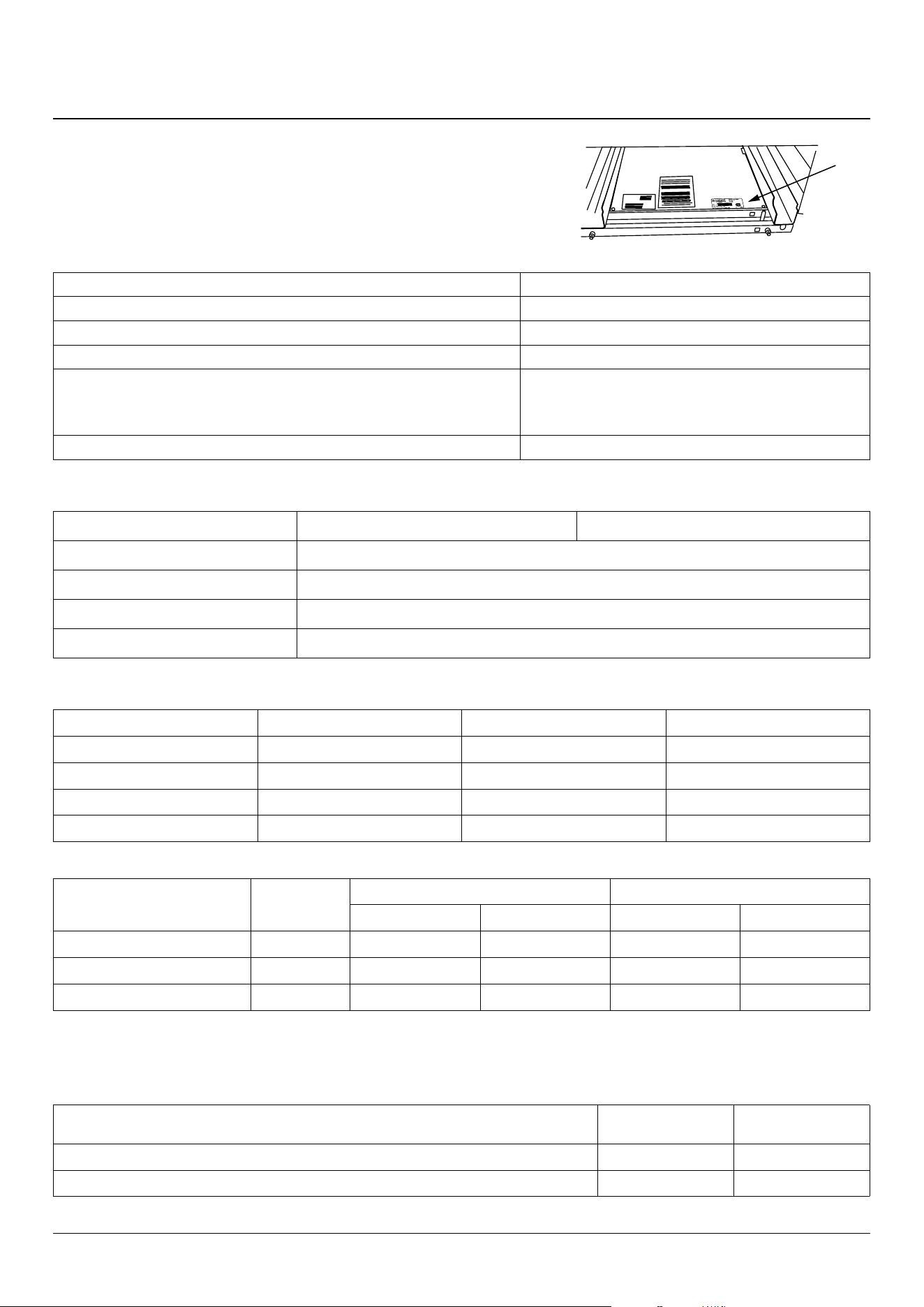
46
18. Technical data
INSTALLER: Please leave these instructions with the user.
DATA BADGE LOCATION: Inside base drawer of cavity. Remove the drawer
(see Overview > Storage for details).
COUNTRY OF DESTINATION: USA, Canada, Mexico.
Connections
Electric Supply 240 V 60 Hz
Electric Rating 240V (2 Wire + N + Grd), 60Hz, 7.4 kW
Branch Circuit Protection 35 A
Connection Type NEMA 14-50 P
Maximum total electric load 240 V (including oven fans, lights, etc.):
* Load demand diversity calculation according to NFPA 70 article 220. Note: The
maximum input at any time is given as both ovens fanned and broiler, plus cooling fan.
7.4 k W, (31 A)*
Gas Connection ½” NPT at rear right-hand side
Dimensions
Overall height minimum 36 1/16” (916 mm) maximum 37 3/16” (941mm)
Overall width 47 9/16” (1208 mm); see ‘Positioning of Range’.
Overall depth 27 7/8” (708 mm)
Minimum space above cooktop 31 ½” (800 mm)
Weight (unpacked) 337 LBS (153 Kg)
Ratings
Oven Left-hand Oven Right-hand Oven Broiler
Fan element 2.5 kW 2.5 kW 2.3 / 1.15 kW
Top element 1.2 kW - -
Browning element 1.15 kW - -
Bottom element 1.0 kW - -
Gas Top
Bypass
Screw*
Natural Gas 4” WC Propane Gas 10” WC
Input Orice Input Orice
Centre burners 55 17,000 btu/hr 205 17,000 btu/hr 118
Larger burners 41 12,000 btu/hr 150 12,000 btu/hr 99
Right-hand front burner 33 6,000 btu/hr 112 6,000 btu/hr 68
* The valves in this range are tted with adjustable bypass screws. The range is supplied with the bypass screws set for Natural gas. For LPG conversion the
bypass screws must be screwed all the way down.
Oven data
Ovens
Left-hand
Multi-function
Right-hand
Convection
Maximum total electric load 240 V
2.5 kW 2.5 kW
Usable volume (cubic feet) 2.77 2.79
47
CONSUMER WARRANTY
ENTIRE PRODUCT – LIMITED ONE YEAR WARRANTY
Any cosmetic faults must be reported within 7 days of installation.
AGA warrants the replacement or repair of all parts of this range which prove to be defective in material or
workmanship, with the exception of the painted or porcelain enamel nish or plated surfaces, for one year from
the date of original purchase. Such parts will be repaired or replaced at the option of AGA without charge, subject
to the terms and conditions set out below.
The warranty period against defects in the painted or porcelain enamel nish, or plated surfaces, is 90 days from
the date of original purchase. The warranty does not include replacement of oven lamps.
OVEN ELEMENTS - LIMITED SECOND THROUGH THIRD YEAR WARRANTY
AGA warrants the oven heating elements against defects in material or workmanship for an additional two
years. These parts will be repaired or replaced at the discretion of AGA without charge, but you pay for labor and
transportation subject to the terms and conditions set out below.
TERMS AND CONDITIONS
1. This warranty applies only for single family domestic use when the range has been properly installed
according to the instructions supplied by AGA and is connected to an adequate and proper utility service.
Damage due to faulty installation, improper usage and care, abuse, accident, re, ood, acts of God, commercial,
business or rental use, and alteration, or the removal or defacing of the serial plate, cancels all obligations of this
warranty. Service during this warranty must be performed by a factory Authorized Service Person.
2. Warranty applies to product only in the country in which it was purchased.
3. AGA is not liable for any claims or damages resulting from any failure of the range or from service delays
beyond their reasonable control.
4. To obtain warranty service, the original purchaser must present the original Bill of Sale, Model and Serial
number. Components repaired or replaced are warranted through the remainder of the original warranty
period only.
5. The warranty does not cover expenses involved in making this appliance readily accessible for servicing.
6. This warranty gives you specic legal rights. Additional warranty rights may be provided by law in some areas.
7. Adjustments such as calibrations, leveling, tightening of fasteners, or utility connections normally associated
with original installation are the responsibility of the dealer or installer and not that of the Company.
TO ENSURE PROMPT WARRANTY SERVICE, SEND IN YOUR WARRANTY CARD WITHIN 10 DAYS OF PURCHASE.
If further help is needed concerning this warranty, contact:
PLACE OF PURCHASE ________________________________
DATE OF PURCHASE _________________________________
SERIAL NUMBER ____________________________________
MODEL NUMBER ___________________________________
Middleby Residential
4960 Golden Pkwy
BLDG 3
Buford, GA 30518
Business 770.932.7282
Fax 770.932.7292
Toll Free Telephone 800.241.9152


www.aga-ranges.com
By AGA made for :
Middleby Residential
4960 Golden Pkwy
BLDG 3
Buford, GA 30518
Business 770.932.7282
Fax 770.932.7292
Toll Free Telephone 800.241.9152