© KEYENCE CORPORATION, 1999 BL600-UM-3-1100 Printed in Japan
BL-600 Series
User’s Manual
User’s Manual
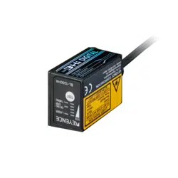
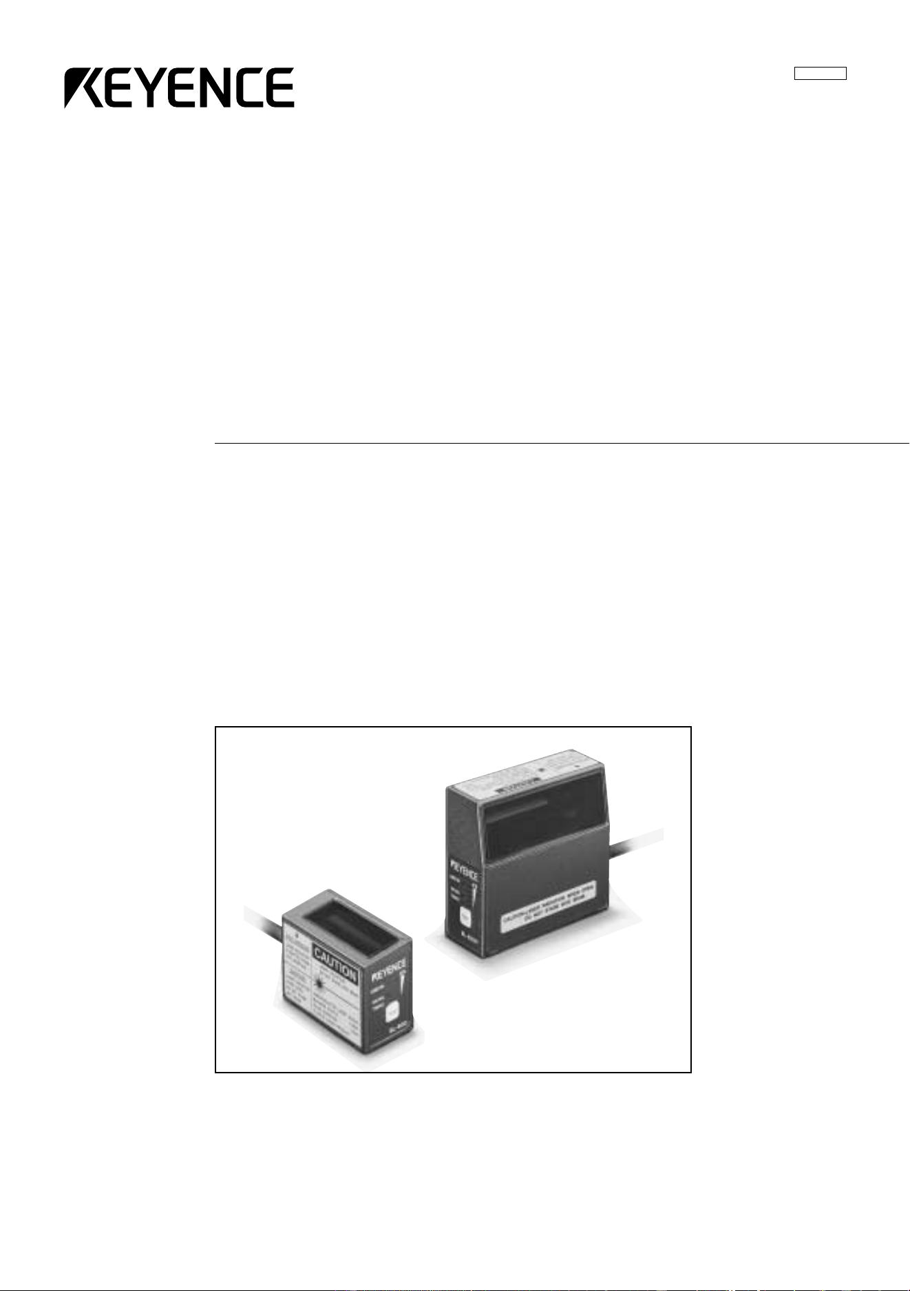
Laser Bar Code Reader
BL-600 Series
96M0355
Specifications are subject to change without notice.
KEYENCE (MALAYSIA) SDN BHD
PHONE: 03-252-2211 FAX: 03-252-2131
KEYENCE (THAILAND) CO., LTD
PHONE: 02-369-2777 FAX: 02-369-2775
KEYENCE TAIWAN CO., LTD
PHONE: 02-2627-3100 FAX: 02-2798-8925
KEYENCE KOREA CORPORATION
PHONE: 02-563-1270 FAX: 02-563-1271
AFFILIATED COMPANIES
KEYENCE CORPORATION OF AMERICA
PHONE: 201-930-0100 FAX: 201-930-0099
KEYENCE DEUTSCHLAND GmbH
PHONE: 06102-36 89-0 FAX: 06102-36 89-100
KEYENCE (UK) LIMITED
PHONE: 01908-696900 FAX: 01908-696777
KEYENCE FRANCE S.A.
PHONE: 01 47 92 76 76 FAX: 01 47 92 76 77
KEYENCE SINGAPORE PTE LTD
PHONE: 392-1011 FAX: 392-5055
KEYENCE CORPORATION
1-3-14, Higashi-Nakajima, Higashi-Yodogawa-ku,
Osaka, 533-8555, Japan
PHONE: 81-6-6379-2211 FAX: 81-6-6379-2131
Safety Precautions
This instruction manual describes the operation and function of the BL-600. Read
this manual carefully to ensure safe use and maximum performance from your BL-
600. The BL-600 Series uses a semiconductor laser as light source. Before using
the product, see "Laser Safety Precautions" on page 1 to learn the safe and correct
method of using the BL-600 Series.
Symbols
The following symbols alert you to important messages. Be sure to read these
messages carefully.
Failure to follow instruction may lead to injury. (electric
shock, burn, etc.)
Failure to follow instructions may lead to product damage.
Provides additional information on proper operation.
Provides reference information about the operation.
General Precautions
• At startup and during operation, be sure to monitor the functions and perfor-
mance of the BL-600.
• We recommend that you take substantial safety measures to avoid any damage
in the event a problem occurs.
• Do not open or modify the BL-600 or use it in any way other than described in
the specifications.
• When the BL-600 is used in combination with other instruments, functions and
performance may be degraded, depending on operating conditions and the
surrounding environment.
• Do not use the BL-600 for the purpose of protecting the human body.
WARNING
CAUTION
Note:
i
Reference:
Warnings and Cautions Specific to the BL-600
• The BL-600 uses a 5 V DC power supply. Using a different voltage level may
damage the unit.
When using the KEYENCE power supply unit BL-U1, BL-U2, N-42 or N-48,
select the voltage level which can be supplied by the power supply unit. If a
nonconforming power supply is connected, the BL-600 may be damaged.
• Before connecting or disconnecting the cable, be sure to turn off any device
connected to the BL-600 Series. Otherwise, the BL-600 Series may be dam-
aged.
• Do not disassemble or modify the BL-600 Series, as this may cause product
failure.
• Locate cables as far as possible from high-voltage lines and power lines.
Otherwise, generated noise may cause product failure or malfunctions.
• The BL-600 is a precision instrument. If the unit is dropped or shocked, it may
be damaged. Take due consideration when transporting or installing the unit.
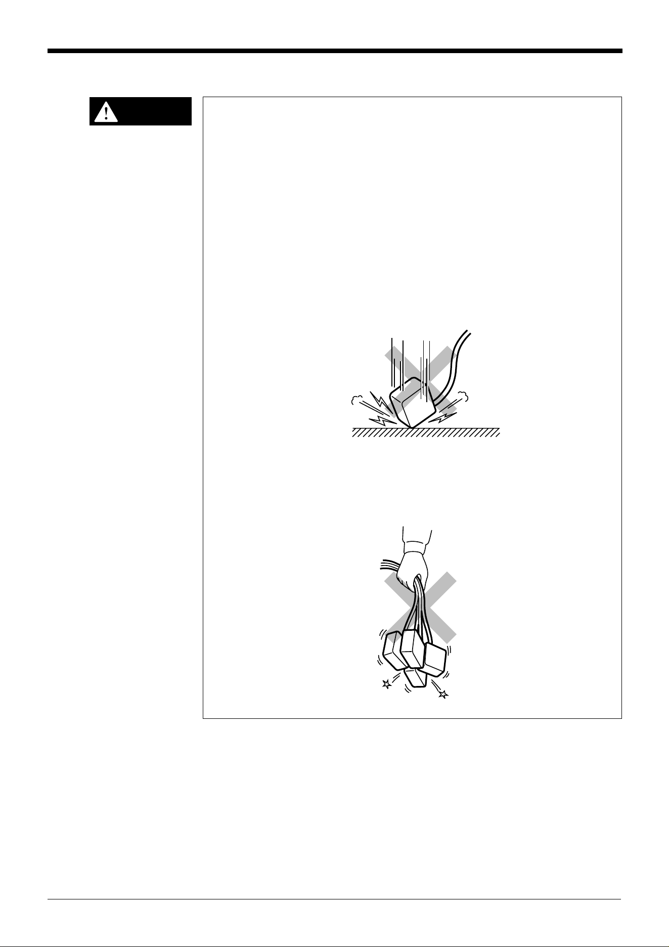
• Do not hold the cables when carrying the units. The units may hit each other
and become damaged.
CAUTION
Incorrect
Incorrect
ii
Environments and conditions for use
To use the BL-600 Series properly and safely, do not install it in locations with the
following conditions. Use of the BL-600 Series in improper environments may
cause fire, electric shock, product failure, damage, or malfunction.
• Locations where the BL-600 Series is exposed to direct sunlight
• Locations where the ambient temperature drops below 0°C or exceeds 45°C
• Locations where the relative humidity drops below 35% or exceeds 85%
• Locations where condensation occurs due to a sudden change in temperature
• Locations where a corrosive or flammable gas exists
• Locations exposed to dust, salt, metal particles, or greasy fumes
• Locations where the ambient light exceeds the range defined in the specifica-
tions
• Locations where the BL-600 Series is directly subjected to vibration or impact
• Locations where water, oil, or chemicals may splash the BL-600 Series
• Locations where a strong magnetic or electric field is generated
If abnormal conditions are encountered
If the following conditions are encountered, turn off the special power supply unit
immediately. Continuing to use the BL-600 Series under abnormal conditions may
cause fire, electric shock, or product failure.
Contact your nearest KEYENCE sales office or distributor (listed at the end of this
manual) for repairs.
• Water or foreign matter enters the BL-600 Series
• The BL-600 Series is dropped or the housing is damaged.
• The BL-600 Series produces smoke or an abnormal smell
Note 1: You cannot perform any operation for 5 seconds after turning ON the BL-
600. During this time, the motor rotation stabilizes. Wait for a while after turning ON
the BL-600, then start reading or another operation.
Note 2: The BL-600 Series has a housing rated as IP-65 (except for the special
power supply unit). It is not affected if water splashes it; however, a proper reading
may not be ensured if the transmitter/receiver is dirty (fingerprints, water, oil, or
dust). In such cases, wipe the dirt off with a soft cloth moistened with alcohol.
iii
CAUTION
CAUTION
iv
2
3
4
5
1
6
7
8
Appendices
How this manual is organized
Chapter 1 Laser Safety Precautions
Chapter 2 Overview
This chapter describes the package contents, basic system configuration, and
operation flow.
Chapter 3 Connection and Wiring
This chapter describes the connections and wiring between the BL-600 Series,
special power supply unit, and peripheral devices.
Chapter 4 Setup Software
This chapter describes the usage of the setup software to set or perform reading
tests of the BL-600.
Chapter 5 Installation
This chapter describes the procedure and cautions for the installation of the BL-600
Series and special power supply unit.
Chapter 6 Reading Operation and Other Functions
This chapter describes the reading operation and other functions, such as test
mode, of the BL-600 Series.
Chapter 7 Serial Communication
This chapter describes the serial communication control.
Chapter 8 PLC Link
This chapter describes the PLC link control.
Appendices
The appendix includes specifications, reading characteristics, dimensions, trouble-
shooting, and index.
Warranties
Warranties

Contents
Chapter 1 Laser Safety Precautions
1.1 Classification ..........................................................................................2
1.2 Warning Labels ......................................................................................2
1.3 Labels Location ......................................................................................3
1.4 Safety Consideration .............................................................................4
1.5 Safety Features Provided with the BL-600 Series ..............................4
Chapter 2 Overview
2.1 Package Contents List and the BL Series Lineup ..............................6
2.2 Part names and functions .....................................................................8
2.3 System Configuration and Connection/Operation Procedures ....... 12
2.3.1 Basic system configuration and connection/
operation procedures for RS-232C communication ............................... 12
2.3.2 Basic system configuration and connection/
operation procedures for RS-422A communication ............................... 13
2.3.3 Multi-drop link communication (RS-485) ................................................ 14
Chapter 3 Connection and Installation
3.1 Connecting BL-U1 and Wiring ............................................................ 16
3.1.1 Connecting the BL-U1, AC power supply, and BL-600 Series ...............16
3.1.2 DIP switch setting ..................................................................................17
3.1.3 Terminals of I/O terminal block and wiring ............................................. 18
3.1.4 Connecting RS-232C ............................................................................. 20
3.1.5 Wiring the RS-422A ...............................................................................23
3.2 Connecting the BL-U2/N-42 and Wiring ............................................. 25
3.2.1 Connecting the BL-U2/N-42, AC power supply, and BL-600 Series ...... 25
3.2.2 Terminals of I/O terminal block and connections ................................... 26
3.2.3 Connecting RS-232C (BL-U2) ...............................................................28
3.2.4 Connecting the N-42 to RS-422A ..........................................................31
3.3 Wiring without the Special Power Supply Units ............................... 33
3.3.1 Pin assignments of the BL-600 Series connector
and the connecting power supply ..........................................................33
3.3.2 I/O Wiring ...............................................................................................34
3.3.3 RS-232C connection ..............................................................................35
Chapter 4 Setup Software
4.1 Installing and Operating the Setup Software .................................... 38
4.1.1 Installation and operation procedures ....................................................38
4.1.2 Installing setup software ........................................................................39
4.1.3 Installation/Start-up ................................................................................39
v

vi
4.1.4 Initial screen ...........................................................................................40
4.1.5 Basic operation ......................................................................................41
4.2 Setup Procedure ..................................................................................42
4.2.1 Model selection ......................................................................................42
4.2.2 [[Main]] (Operation setting) screen .........................................................42
4.2.3 [[Comm Settings-1]] (Communication parameters 1) screen ................. 45
4.2.4 [[Comm Settings-2]] (Communication parameters 2) screen ................. 46
4.2.5 [[Code setup]] (Bar code setting) screen ...............................................49
4.2.6 [[Utility]] screen ......................................................................................53
4.3 Sending/Receiving Settings ................................................................54
4.3.1 Sending/receiving settings to/from the BL-600 Series ........................... 54
4.3.2 Sending/receiving settings to/from the BL-600 Series via the N-400 .....57
4.4 Reading/Saving/Printing File ..............................................................59
4.4.1 [[Files]] screen ........................................................................................59
4.4.2 Reading a previously saved setting file ..................................................59
4.4.3 Saving updated settings in a file ............................................................60
4.4.4 Comparing the contents of the file currently
being edited with a saved file .................................................................61
4.4.5 Printing contents of a setting file ............................................................ 61
4.4.6 Resetting the edited settings to the initial (factory) settings ................... 62
4.5 Using Monitor .......................................................................................62
4.5.1 Receiving data and checking the result .................................................62
4.5.2 Command transmission .........................................................................63
4.5.3 Starting the test mode ............................................................................65
3.5.4 Changing the scanning width ................................................................. 66
4.6 List of Error Messages ........................................................................67
4.7 Example of printing from the setup software ....................................68
Chapter 5 Installation
5.1 Installation of the BL-600 Series ........................................................72
5.1.1 Situations to check for before installing the BL-600 Series ....................72
5.1.2 Mounting angle and distance ................................................................. 74
5.1.3 Mounting the BL-600/601/600HA/601HA ...............................................75
5.1.4 Mounting the BL-650HA/651HA .............................................................77
5.1.5 Mounting the BL-600 Series without the mounting bracket ...................79
5.2 Installation of the Special Power Supply Unit ................................... 81
5.2.1 In-panel installation ................................................................................81
5.2.2 Installing the BL-U1 ................................................................................81
5.2.2 Installing the BL-U2 and N-42 ................................................................83
Chapter 6 Functions for Reading Operation
6.1 Read Operation ....................................................................................86
6.1.1 Scanning method ...................................................................................86
6.2 Read Modes ..........................................................................................88
6.2.1 Single label read mode ..........................................................................88

6.2.2 Multi-label read mode 1 (Multi 1) ...........................................................89
6.2.3 Multi-label read mode 2 (Multi 2) ...........................................................90
6.2.4 Multi-label read mode 3 (Multi 3) ...........................................................91
6.3 Label Orientation Mode ....................................................................... 93
6.4 Test Mode .............................................................................................94
6.4.1 Reading rate check mode ...................................................................... 94
6.4.2 Tact check mode ....................................................................................97
6.4.3 Online test mode ....................................................................................99
6.5 Preset Function (Compare with:) .....................................................101
6.5.1 Preset function .....................................................................................101
6.5.2 Using “?” and “!” in the preset data ......................................................101
6.6 Additional information function .......................................................102
6.6.1 Decode match count add function .......................................................102
6.6.2 Scan count add function
(valid only if using the decoding count add function) ...........................102
6.6.3 Code type add function ........................................................................103
6.6.4 Label orientation add function ..............................................................103
6.6.5 Symbology ID add function ..................................................................104
6.6.6 PMI add function ..................................................................................104
6.6.7 Order of the additional information .......................................................106
6.7 Max. Code Length (Designated Digit ) Output Function ................ 107
Chapter 7 Serial Communication
7.1 Serial Communication .......................................................................110
7.2 Details on Data Communication .......................................................111
7.3 Command Communication ...............................................................114
7.3.1 Setup of direct control commands .......................................................114
7.3.2 Details on parameter setting commands .............................................118
Chapter 8 PLC Link
8.1 PLC Link .............................................................................................130
8.1.1 List of PLCs used for PLC link .............................................................130
8.1.2 Devices used for PLC link ....................................................................131
8.2 Setting the BL-600 and PLC ..............................................................132
8.2.1 Setting the BL-600 Series ....................................................................132
8.2.2 Setting the PLC ....................................................................................132
8.3 Device Assignment ............................................................................135
8.3.1 Data memory head address .................................................................135
8.3.2 Data memory areas .............................................................................136
8.3.3 Detailed description of device assignment ...........................................137
8.4 PLC Link Error ....................................................................................142
8.5 Communication Time ........................................................................143
vii

viii
Appendices
Appendix A BL-600 Series Specifications ...............................................146
Appendix A.1 Specifications ..........................................................................146
Appendix A.2 Reading Range Characteristics (Typical) ............................... 148
Appendix A.3 Angular Characteristics (Typical) ............................................ 151
Appendix B BL-U1 Specifications ............................................................152
Appendix C BL-U2, N-42 Specifications ..................................................153
Appendix D Dimensions ...........................................................................154
Appendix E Sample Program for the PLC Link ......................................159
Appendix F Troubleshooting ...................................................................162
Appendix F.1 Bar codes cannot be read .......................................................162
Appendix F.2 Reading rate check mode is not 100% ...................................163
Appendix F.3 The setting data cannot be sent/
received using the setup software ..........................................163
Appendix F.4 Cannot communicate successfully when using the PLC link .....163
Appendix G CODE93 Specifications ........................................................164
Appendix H CODE128 Specifications ......................................................165
Appendix I Checksum Calculation Method ........................................... 167
Appendix J ASCII Code Table .................................................................. 169
Appendix K Setup Parameter List ............................................................170
Appendix L Default Setting List ...............................................................173
Warranties
WARRANTIES AND DISCLAIMERS ............................................................ 181


Chapter 1
Laser Safety Precautions
1.1 Classification ........................................................................2
1.2 Warning Labels .....................................................................2
1.3 Label Location ......................................................................3
1.4 Safety Consideration ............................................................4
1.5 Safety Features Provided with the BL-600 Series ............. 4
Chapter 1 Laser Safety Precautions
1
2
1.1 Classification
Model BL-600/601/600HA/601HA BL-650HA/651HA
FDA Class II
IEC 825-1 11.1993 Class 2
DIN EN 60825-1 07.1994 Klasse 2
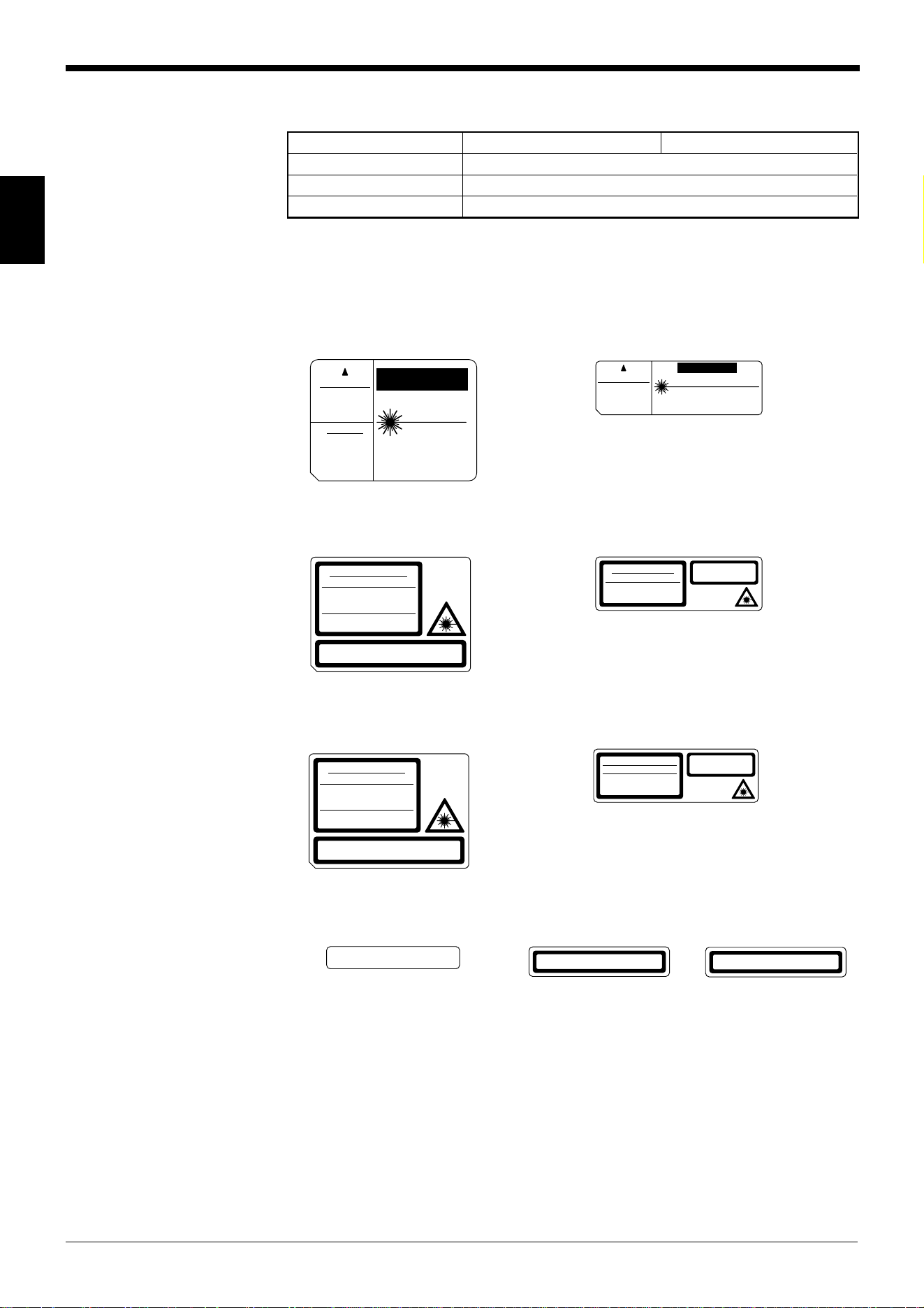
1.2 Warning Labels
1) Warning labels
■ FDA
BL-600/601/600HA/601HA BL-650HA/651HA
■ IEC
BL-600/601/600HA/601HA BL-650HA/651HA
■ DIN
BL-600/601/600HA/601HA BL-650HA/651HA
2) Protective housing label
■ FDA ■ IEC ■ DIN
LASER RADIATION
WHEN OPEN.
DO NOT STARE
INTO BEAM.
CAUTION
LASER RADIATION
-
DO NOT STARE INTO BEAM.
LASER RADIATION
IS EMITTED FROM
THIS APERTURE.
SEMICONDUCTOR LASER 650 nm
MAXIMUM OUTPUT 1.5 mW
PULSE DURATION 56 µs
CLASS II LASER PRODUCT
AVOID EXPOSURE
CAUTION
CAUTION
LASER RADIATION
-
DO NOT STARE INTO BEAM.
AVOID EXPOSURE
LASER RADIATION
IS EMITTED FROM
THIS APERTURE.
SEMICONDUCTOR LASER 650 nm
MAXIMUM OUTPUT 1.5 mW
PULSE DURATION 56 µs
CLASS II LASER PRODUCT
LASER RADIATION
DO NOT STARE INTO BEAM
Maximum output
Pulse duration
Emitted wavelength
1.5 mW
82 µs
650 nm
CLASS 2 LASER PRODUCT
in conformity to
IEC 60825
-
1 1998
-
01
LASER RADIATION
DO NOT STARE INTO BEAM
Maximum output
Pulse duration
Emitted wavelength
CLASS 2 LASER PRODUCT
1.5 mW
99 µs
650 nm
in conformity to IEC 60825
-
1 1998
-
01
CAUTION
- Laser radiation when open.
Do not stare into beam.
LASERSTRAHLUNG
NICHT IN DEN STRAHL BLICKEN
1.5 mW
82 µs
650 nm
Maximum Leistung
Pulsdauer
Wellenlänge
LASER KLASSE 2
nach Entwurf DIN EN
60825
-
1 1998
-
01
LASERSTRAHLUNG
NICHT IN DEN STRAHL BLICKEN
Maximum Leistung
Pulsdauer
Wellenlänge
LASER KLASSE 2
1.5 mW
99 µs
650 nm
nach Entwurf DIN EN 60825
-
1 1998
-
01
VORS IC HT
- Laserstrahlung wenn Abdeckung
geöffnet. Nicht in den Strahl blicken.
CAUTION
- Laser radiation when open.
Do not stare into beam.
VORS ICH T
- Laserstrahlung wenn Abdeckung
geöffnet. Nicht in den Strahl blicken.
CAUTION-LASER RADIATION WHEN OPEN.
DO NOT STARE INTO BEAM.
Chapter 1 Laser Safety Precautions
1
3
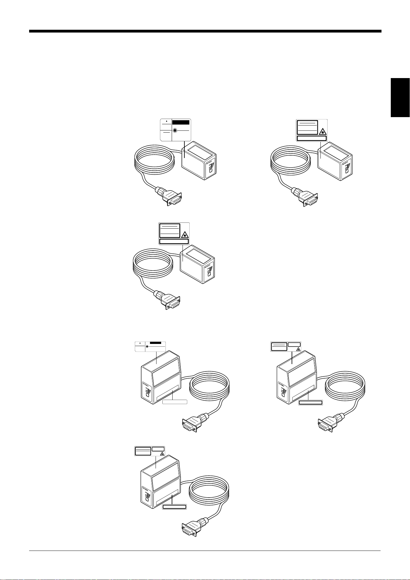
1.3 Labels Location
FDA Warning labels are attached to the sensor head as shown below.
The IEC/DIN Warning labels are packaged with the BL-600 series. Affix the Warn-
ing labels on the sensor head as shown below.
■ BL-600/601/600HA/601HA
FDA IEC
DIN
■ BL-650HA/651HA
FDA IEC
DIN
L
A
S
E
R
O
N
O
K
/N
G
T
I
M
I
N
G
TEST
BL-600
LASER RADIATION
WHEN OPEN.
DO NOT STARE
INTO BEAM.
CAUTION
LASER RADIATION
-
DO NOT STARE INTO BEAM.
LASER RADIATION
IS EMITTED FROM
THIS APE RTURE.
SEMICONDUCTOR LASER 650 nm
MAXIMUM OUTPUT 1.5 mW
PULSE DURATION 56 µs
CLASS II LASER PRODUCT
AVOID EXPOSURE
CAUTION
L
A
S
E
R
O
N
O
K
/N
G
T
I
M
I
N
G
TES
T
BL-600
CAUTION
LASER RADIATION
-
DO NOT STARE INTO BEAM.
AVOID EXPOSURE
LASER RADIATION
IS EMITTED FROM
THIS APE RTURE.
SEMICONDUCTOR LASER 650 nm
MAXIMUM OUTPUT 1.5 mW
PULSE DURATION 56 µs
CLASS II LASER PRODUCT
CAUTION-LASER RADIATION WHEN OPEN.
DO NOT STARE INTO BEAM.
L
A
S
E
R
O
N
O
K
/
N
G
T
I
M
I
N
G
TE
ST
B
L-600
LASER RADIATION
DO NOT STARE INTO BEAM
Maximum output
Pulse duration
Emitted wavelength
CLASS 2 LASER PRODUCT
1.5 mW
99 µs
650 nm
in conformity to IEC 60825
-
1 1998
-
01
CAUTION
- Laser radiation when open.
Do not stare into beam.
L
A
S
E
R
O
N
O
K
/N
G
T
I
M
I
N
G
TEST
BL-600
LASERSTRAHLUNG
NICHT IN DEN STRAHL BLICKEN
Maximum Leistung
Pulsdauer
Wellenlänge
LASER KLASSE 2
1.5 mW
99 µs
650 nm
nach Entwurf DIN E N 60825
-
1 1998
-
01
VORSICHT
- Laserstrahlung wenn Abdeckung
geöffnet. Nicht in den Strahl blicken.
L
A
S
E
R
O
N
O
K
/N
G
T
I
M
I
N
G
TES
T
BL-600
LASER RADIATION
DO NOT STARE INTO BEAM
Maximum output
Pulse duration
Emitted wavelength
1.5 mW
82 µs
650 nm
CLASS 2 LASER PRODUC T
in conformity to
IEC 60825
-
1 1998
-
01
CAUTION
- Laser radiation when open.
Do not stare in to beam.
L
A
S
E
R
O
N
O
K
/
N
G
T
I
M
I
N
G
TEST
BL-600
LASERSTRAHLU NG
NICHT IN DEN STRAHL BLICKEN
1.5 mW
82 µs
650 nm
Maximum Leistung
Pulsdauer
Wellenlänge
LASER KLASSE 2
nach Entwurf DIN EN
60825
-
1 1998
-
01
VOR SI C HT
- Laserstrahlung wenn Abdeckung
geöffnet. Nicht in den Strahl blicken.

Chapter 1 Laser Safety Precautions
1
4
1.4 Safety Consideration
Use of controls or adjustment, or the performance of procedures other than those
specified herein, may result in hazardous radiation exposure.
The laser beam is not harmful to the skin. There is, therefore, no danger in expos-
ing arms or hands to the beam. The only possible health hazard is in exposing the
eyes to the laser beam. Damage to the eyes can occur if the operator stares
directly into the beam.
Follow the safety precautions below to ensure operator safety:
• Operate the BL-600 Series only according to the procedures described in
this instruction manual.
Otherwise, injury may occur due to exposure to the laser beam.
• Do not disassemble the sensor head.
Laser emission from the BL-600 series is not automatically stopped if the
sensor head is disassembled. If you disassemble the sensor head for inspection
or repair, you may be exposed to the laser beam. If the BL-600 series malfunc-
tions, contact KEYENCE immediately.
• Do not look directly at the laser beam.
Looking directly at the laser beam may result in serious eye injury.
• Protective enclosure
We recommend that you install a protective enclosure around the sensor head
to prevent any person from getting near the sensor head during operation.
• Protective goggles
We recommend that you wear protective goggles when using the BL-600
series.
• Stop laser emissions before cleaning the laser emission port.
Failure to stop the laser emission may expose eyes to the laser beam.
• Check the laser beam path.
To prevent exposure to the laser beam due to specular or diffuse reflection,
install a screen which offers the appropriate reflectance and temperature
characteristics to interrupt the reflected laser beam. Do not install the BL-600
series in such a way that the laser beam passes at eye height.
1.5 Safety Features Provided with the BL-600 Series
The BL-600 series is provided with the following safety features. Make sure these
features function correctly before operating.
• Laser emission caution LED (LASER ON LED)
During laser emission, the LASER ON LED illuminates. The LED ON status can
be checked through the laser protective glasses.
• Laser forced OFF command
Sending the laser forced OFF command (LOCK, see page 116) to the BL-600
can inhibit emission of laser beams. When working near the laser transmitter,
be sure to use the laser forced OFF command to avoid looking into the laser
beams.
When this command is selected, the bottom STABILITY LED flashes.
CAUTION
WARNING

Chapter 2
Overview
This chapter describes the package contents, basic system configuration, and
operation flow.
2.1 Package Contents List and the BL Series Lineup .............. 6
2.2 Part Names and Functions ................................................... 8
2.3 System Configuration and Connection/
Operation Procedures .........................................................12
2.3.1 Basic system configuration and connection/operation proce-
dures for RS-232C communication........................................12
2.3.2 Basic system configuration and connection/operation proce-
dures for RS-422A communication ........................................ 13
2.3.3 Multi-drop link communication (RS-485)................................ 14
Chapter 2 Overview
2
6
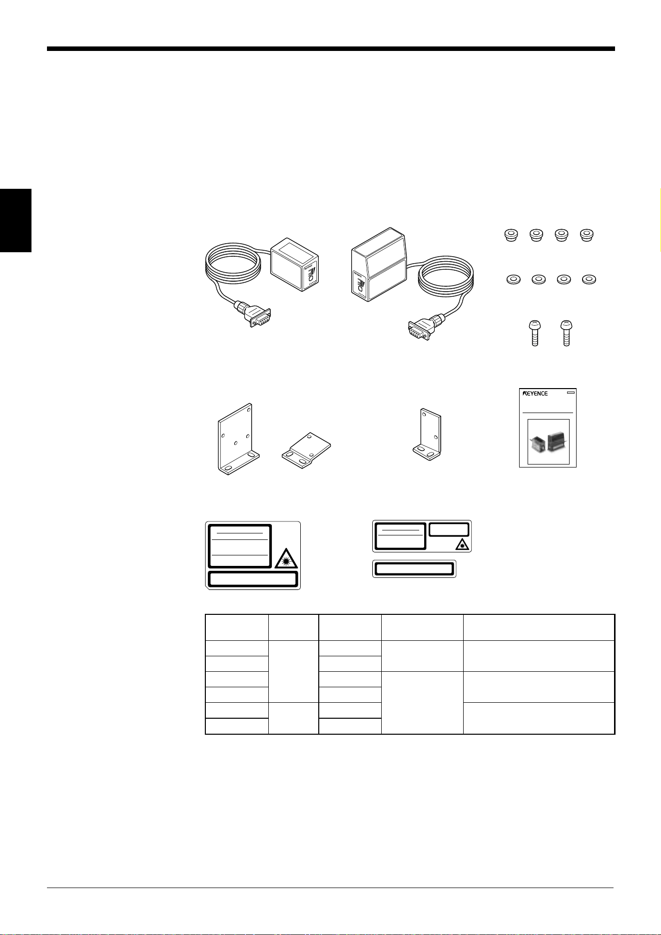
2.1 Package Contents List and the BL Series Lineup
The packages of the BL-600 Series, optional power supply unit, and setup software
contain the following components. Be sure to check that you have all the package
contents before use.
Laser bar code reader
BL-600 Series (BL-600/601/600HA/601HA/650HA/651HA)
Laser bar code reader: 1
BL-600/601/600HA/601HA BL-650HA/651HA Insulating spacer: 4
Washer: 4
Mounting screw (M3): 2
BL-600/601/600HA/601HA BL-650HA/651HA
Mounting bracket Mounting bracket : 1 Instruction manual: 1
A and B: 1 each
Laser warning label (Japanese/English/German/French): 1
BL-600/601/600HA/601HA BL-650HA/651HA
LASER O
N
O
K
/
N
G
TIM
ING
TES
T
LASER ON
O
K
/
N
G
TIMING
T
E
S
T
LASER RADIATION
DO NOT STARE INTO BEAM
Maximum output
Pulse duration
Emitted wavelength
CLASS 2 LASER PRODUCT
1.5 mW
99 µs
650 nm
in conformity to IEC 60825
-
1 1998
-
01
CAUTION
- Laser radiation when open.
Do not stare into beam.
LASER RADIATION
DO NOT STARE INTO BEAM
Maximum output
Pulse duration
Emitted wavelength
1.5 mW
82 µs
650 nm
CLASS 2 LASER PRODUCT
in conformity to
IEC 60825
-
1 1998
-
01
CAUTION
- Laser radiation when open.
Do not stare into beam.
ledoM
gnidaeR
noitcerid
gninnacS
dohtem
rabelbadaeR
htdiw
ecnatsidgnidaeR
006-LB
tnorF
elgniS
mm0.1ot91.0
mm033ot57
)mm0.1sihtdiwworrannehW(
106-LB retsaR
AH006-LB elgniS
mm0.1ot521.0
mm091ot53
)mm5.0sihtdiwworrannehW(
AH106-LB retsaR
AH056-LB
ediS
elgniS
mm571ot54
)mm5.0sihtdiwworrannehW(
AH156-LB retsaR
Laser Bar Code Reader
BL-600 Series
Instruction Manual
058-069
Chapter 2 Overview
2
7
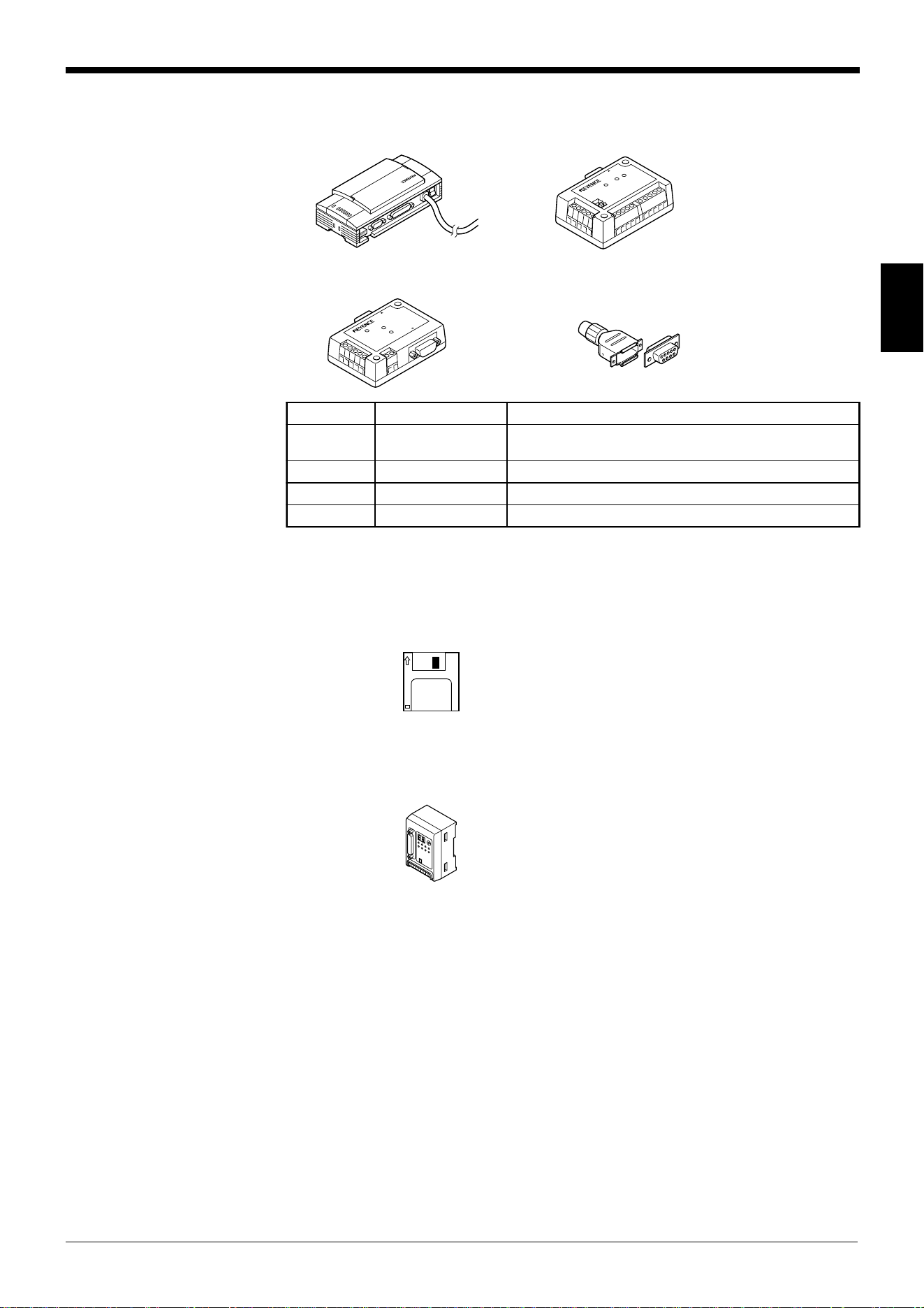
Power supply (Option)
■ BL-U1 ■ N-42/N-48
■ BL-U2 D-sub 9-pin connector,
connector case: 1 each
Setup software (Option)
■ BL-H60WE
Setup software
3.5-inch floppy disk: 1
Other options
■ N-400: Multi-drop controller
Used as the master unit when multi-drop linking with the BL Series.
The package contents have been carefully inspected; however, if any component
should be defective or damaged, contact your nearest KEYENCE office or distribu-
tor (listed at the end of this manual).
■ OP-27937: RS-232C Null modem cable (D-sub 9-pin)
Used for connecting BL-600 reader to optional power supply units
BL-U2.
■ OP-22149: RS-232C Null modem cable
Used for connecting BL-600 reader to optional power supply units
BL-U1.
■ OP-25057: 25-to 9-pin adaptor
TERMINATOR
ON
OFF
PO
W
ER
SD
R
D
R
E
ADE
R
POWER
SD
RD
READER
RS-232C
ledoMegatlovylppuSecafretnI
1U-LB CAV042ot001
)knilpord-itlum(584-SRro,A224-SR,C232-SR
)esehtfoenotceleS(
2U-LB CDV42C232-SR
24-N CDV42A224-SR
84-N CDV42)knilpord-itlum(584-SR
Chapter 2 Overview
2
8
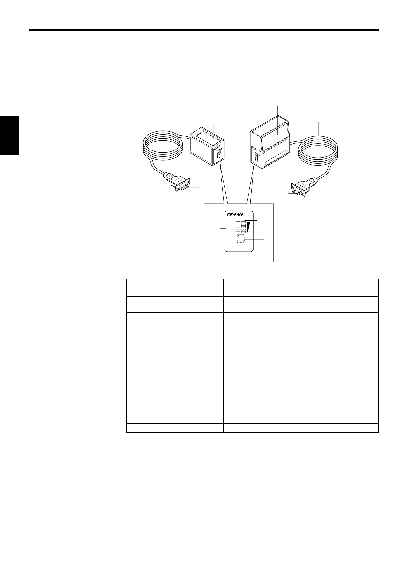
2.2 Part Names and Functions
This section describes the part names and functions of the BL-600 Series and
special power supply unit.
■ BL-600/601/600HA/601HA ■ BL-650HA/651HA
L
ASER
O
N
O
K
/
N
G
T
I
M
I
N
G
T
E
S
T
B
L
-
6
0
0
L
ASE
R O
N
O
K
/
N
G
T
I
M
I
N
G
T
E
S
T
B
L
-
6
0
0
LASER ON
OK/NG
TIMING
TEST
BL-600
1
2
3
4
5
7
8
6
6
8
7
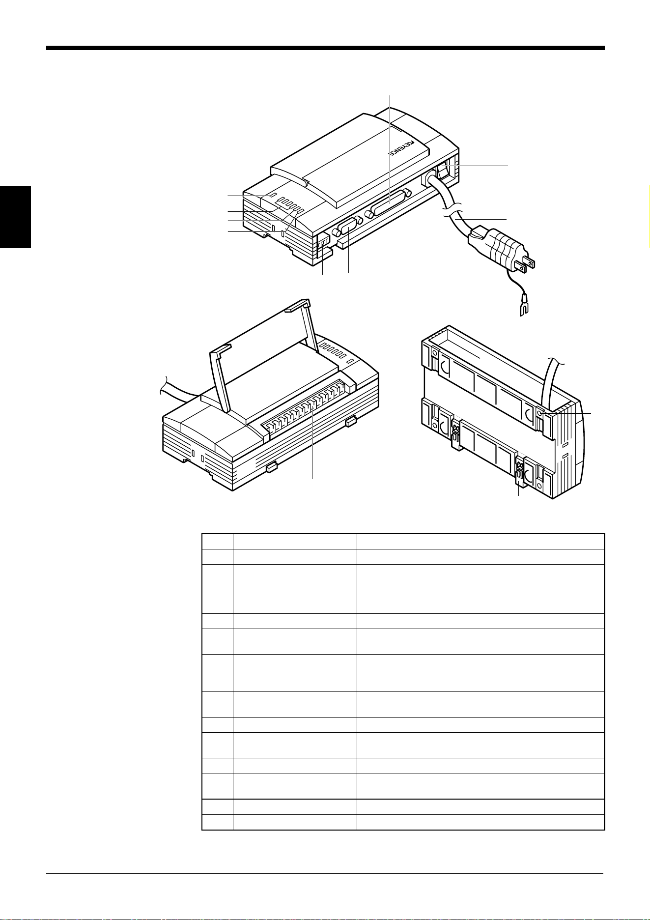
.oNemaNnoitcnuF
1DELNORESAL.dettimeerasmaebresalnehwtiL
2DELGN/KO
.sthgilDELneergehT:NOsituptuoKOnehW•
.sthgilDELderehT:NOsituptuoGNnehW•
3DELGNIMIT.NOsitupnireggirtnehwtiL
4DELYTILIBATS
ytilibatsgnidaerehtsyalpsiD
(➮ ).001,89,59segapeeS
.sutatsgnitarepo006-LBehtdna
(➮ ehtnoelbatehteeS
).egaptxen
5HCTIWSTSET
:snoitarepogniwollofehtswollahctiwssihT
.edomtxetehttratS•
sdaersetunimowtnihtiwecnohctiwsehtgnisserP•
.ecnoedocrabeht
ehtotlocotorpnoitacinummocehtsteS•seulavlavitni
.sgnittesehtgnidnesnehw
(➮ ).45egapeeS
.sutatsrorreehtteseR•
6reviecer/rettimsnarT
detcelfereviecerdnasmaebresaltimeotwodniW
.sthgil
7rotcennocylppusrewoP.tinuylppusrewoplaicepsehtotdetcennoC
8elbaC.m9.1sihtgnelelbaC
Chapter 2 Overview
2
9
STABILITY LED display according to the operating status
sutatsgnitarepOyalpsidDELYTILIBATSnekatebotnoitcA
no-rewoP
yllaitneuqesnonrutsDEL
.mottobehtmorfgnitrats
––––––
putesgniruD
➮ .811,611segapeeS
.hsalfsDELehtllA ––––––
atadgnittesrofgnitiaW
eviecer/dnes
➮ .45egapeeS
htfifdna,driht,tsrifehT
hsalfpotehtmorfsDEL
.ylsuoenatlumis
––––––
FFOdecrofresaL
➮ sidnammocKCOLnehW
.611egapees,tnes
.sehsalfDELmottobehT ––––––
rorretinU
,driht,dnocesehtforehtiE
potehtmorfsDELhtrofro
.sehsalf
evahyamseireS006-LBehT
yamegatlovylppusehtrodeliaf
siegatlovehtfI.deppordevah
aevahyamtinueht,lamron
tseraenruoytcatnoC.melborp
.rotubirtsidroeciffoECNEYEK
rorreknilCLP
➮ .241egapeeS
.sehsalfDELpotehT
teserothctiwsTSETehtsserP
.rorreeht
Chapter 2 Overview
2
10
■ BL-U1
6
1
2
3
4
9
10
78
5
12
11
.oNemaNnoitcnuF
1DELREWOP.NOsirewopnehwtiL
2
sutatsnoitacinummoC
sDELrotacidni
fosutatsnoitacinummocehtrotinomotuoyswollA•
.tropC232-SReht
nidedivorperasrotacidniSCdnaSR,DR,DSehT•
.potehtmorfredrosiht
3DELGNIMIT.NOsitupnireggirtnehwtiL
4DELGN/KO
.sthgilDELneergehT:NOsituptuoKOnehW•
.sthgilDELderehT:NOsituptuoGNnehW•
5kcolblanimretO/I
tuptuoGN/KO,lanimrettupnireggirtehtsedulcnI
)knilpord-itlum(584-SR/A224-SRdna,slanimret
.slanimretgnitcennoc
6tropC232-SR
sitropsihT.retupmoclanosrepaottcennocotdesU
.desusi)knilpord-itlum(584-SRnehwdesunu
7tropREDAER.tropsihtotseireS006-LBehttcennoC
8sehctiwsPID
ehtsnrutdna,tropnoitacinummocehtsehctiwS
.FFO/NOrotanimret
9hctiwsrewoP.FFO/NOrewopehtsnuT
01elbacylppusrewoP
.ylppusrewop)zH06/05(CAV042ot001aesU
.m2sithgnelelbaC
11tekcarbgnitnuoM .swercshtiwdetnuomsi1U-LBehtnehwdesU
21walcgnitnuomliar-NID .liarNIDaotdetnuomsi1U-LBehtnehwdesU
Chapter 2 Overview
2
11
■ BL-U2
■ N-42
POWER
SD
RD
READER
RS-232C
8
1
2
3
8
4
5
6
7
.oNemaNnoitcnuF
1tropREDAER.redaeredocrabseireS006-LBaottcennoC
2slanimrettupniREGGIRT .tupnireggirtrofrosnescirtceleotohpaottcennoC
3slanimrettuptuoGN/KO.slangisGN/KOtuptuO
4slanimretylppusrewoP.ylppusrewopCDV42aottcennoC
5tropC232-SR.cte,retupmoclanosrepaottcennoC
6
sutatsnoitacinummoC
sDELrotacidni
.C232-SRehtfosutatsnoitacinummocehtetacidnI•
redrosihtnidedivorperasrotacidniDRdnaDSehT•
.potehtmorf
7DELREWOP.nosirewopehtnehwthgiL
8elohgnitnuoM .swercshtiwdetnuomsi2U-LBehtnehwdesU
TERMINATOR
ON
OFF
POWER
SD
RD
READER
1
3
2
4
5
9
6
7
98
.oNemaNnoitcnuF
1tropREDAER.redaeredocrabseireS006-LBaottcennoC
2hctiwsrotanimreT
rotanimretehtFFO/NOsnruT
001:ecnatsisernoitanimreT( Ω .)
3slanimrettupniREGGIRT .tupnireggirtrofrosnescirtceleotohpaottcennoC
4slanimrettuptuoGN/KO.slangisGN/KOtuptuO
5slanimretylppusrewoP.ylppusrewopCDV42aottcennoC
6slanimretA224-SR.ecivedA224-SRnaottcennoC
7
sutatsnoitacinummoC
sDELrotacidni
.A224-SRehtfosutatsnoitacinummocehtsetacidnI•
redrosihtnidedivorperasrotacidniDRdnaDSehT•
.tfelehtmorf
8DELREWOP.NOdenrutsirewopehtnehwthgiL
9elohgnitnuoM.swercshtiwdetnuomsi24-NehtnehwdesU
Chapter 2 Overview
2
12
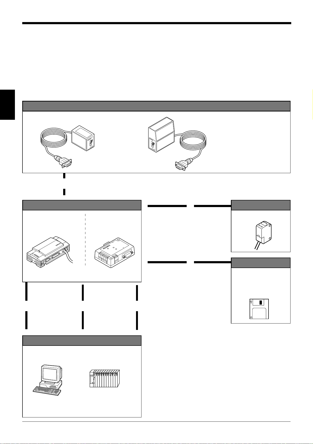
2.3 System Configuration and Connection/Operation Proce-
dures
This section describes the basic system configuration and the connection/operation
procedures to use RS-232C, RS-422A, or multi-drop link.
2.3.1 Basic system configuration and connection/operation procedures for
RS-232C communication
L
A
S
E
R
O
N
OK/NG
T
IM
I
N
G
TE
S
T
L
A
S
E
R
O
N
O
K
/
N
G
T
I
M
I
N
G
T
E
S
T
BL-600 Series
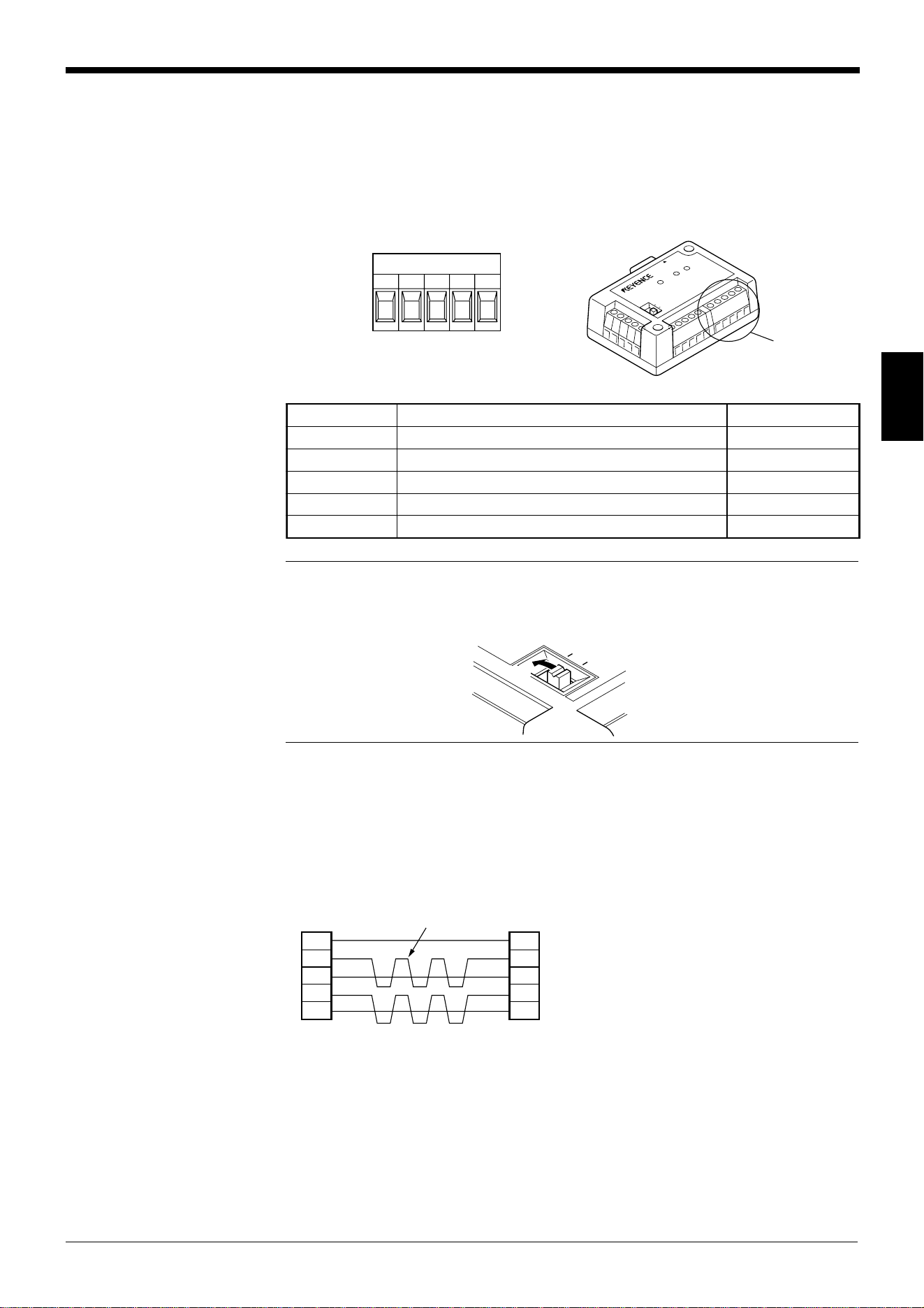
BL-600/601/600HA/601HA
BL-650HA/651HA
Installation
➮
See pages 72 to 80.
• Check before installation
• Position adjustment using
test mode
• Installation
▼
Connection to the READER port
With the BL-U1
➮
See page 16.
With the BL-U2
➮
See page 25.
Optional power supply unit
POWER
SD
RD
READER
RS-232C
6
1
Power-up
DIP switch setting
➮
See page 17.
2
4
Trigger input
Photoelectric sensor
Host computer
▼
3
Connection
With the BL-U1
➮
See pages 20 to 23.
With the BL-U2
➮
See pages 28 to 30.
▼
8
Serial communi-
cation
➮
See “Chapter 7,
Serial Communication.”
PLC link
➮
See “Chapter 8, PLC Link.”
▼
PC
PLC (RS-232C link unit)
▼
9
7
Connection
With the BL-U1 ➮
See page 19.
With the BL-U2 ➮
See page 27.
▼
5
Setting of the BL-600 Series
(Use one of these setup tools.)
Setup tools
Setup software
BL-H60WE
➮
See “Chapter 4, Setup
Software.”
▲▲
BL-U1 BL-U2
Chapter 2 Overview
2
13
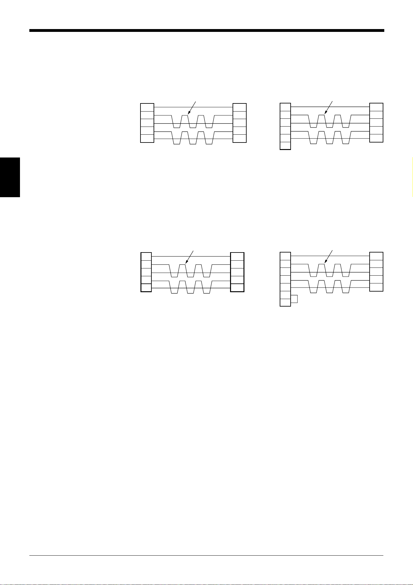
2.3.2 Basic system configuration and connection/operation procedures for
RS-422A communication
LASER ON
O
K
/
N
G
TIMIN
G
T
ES
T
LASE
R ON
O
K
/
N
G
TIMING
T
E
S
T
BL-600 Series
BL-600/601/600HA/601HA
BL-650HA/651HA
Installation
➮
See pages 72 to 80.
• Check before installation
• Position adjustment using
test mode
• Installation
▼
Connection to the READER port
With the BL-U1
➮
See page 16.
With the BL-N42
➮
See page 25.
Optional power supply unit
P
O
W
E
R
S
D
R
D
R
E
A
D
E
R
R
S
-2
3
2
C
6
1
Power-up
DIP switch setting
➮
See page 17.
2
4
Trigger input
Photoelectric sensor
Host computer
▼
3
Connection
With the BL-U1
➮
See pages 23 to 24.
With the BL-N42
➮
See pages 31 to 32.
▼
8
Serial communi-
cation
➮
See “Chapter 7,
Serial Communication.”
PLC link
➮
See “Chapter 8, PLC Link.”
▼
PC
PLC (RS-422A link unit)
▼
9
7
Connection
With the BL-U1 ➮
See page 19.
With the BL-N42
➮
See page 27.
▼
5
Setting of the BL-600 Series
(Use one of these setup tools.)
Setup tools
Setup software
BL-H60WE
➮
See “Chapter 4, Setup
Software.”
▲▲
Note: When the N-42 is used as a power supply unit, the communication type is
set to RS-422A, therefore the BL-600 Series cannot be connected directly to a
personal computer. To set the BL-600 Series with a personal computer, use an
RS-232C type power supply unit (BL-U1 or BL-U2).
Chapter 2 Overview
2
14
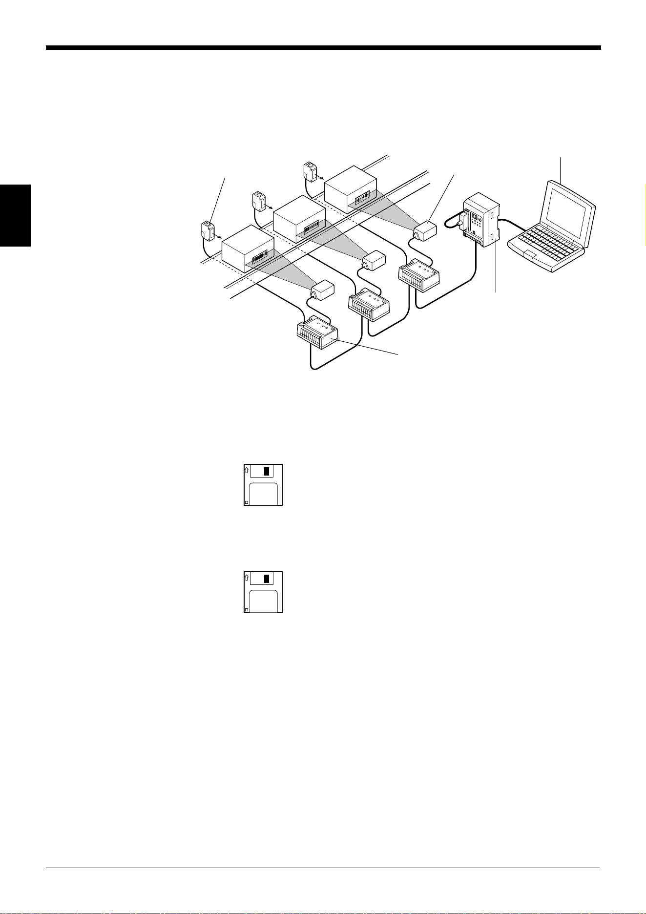
2.3.3 Multi-drop link communication (RS-485)
The following devices are required for the multi-drop link to control several BL-600
Series units with a host computer.
■ BL-600 Series setup tools
Setup software BL-H60WE
■ N-400 setup tools
Setup software (Provided with N-400)
➮
Refer to the N-400 User’s Manual for connection and usage of the multi-drop link.
Photoelectric sensor
(PZ2 Series, etc.)
Host computer (PC)
Multi-drop controller
(N-400)
BL-600 Series
Optional power supply unit
(BL-U1, N-48)

Chapter 3
Connection and Installation
This chapter describes the connections and wiring between the BL-600 Series,
special power supply unit, and peripheral devices.
3.1 Connecting BL-U1 and Wiring ........................................... 16
3.1.1 Connecting the BL-U1, AC power supply,
and BL-600 Series .................................................................16
3.1.2 DIP switch setting ..................................................................17
3.1.3 Terminals of I/O terminal block and wiring............................. 18
3.1.4 Connecting RS-232C.............................................................20
3.1.5 Wiring the RS-422A ...............................................................23
3.2 Connecting the BL-U2/N-42 and Wiring ............................25
3.2.1 Connecting the BL-U2/N-42, AC power supply,
and BL-600 Series .................................................................25
3.2.2 Terminals of I/O terminal block and connections...................26
3.2.3 Connecting RS-232C (BL-U2) ...............................................28
3.2.4 Connecting the N-42 to RS-422A ..........................................31
3.3 Wiring without the Special Power Supply Units .............. 33
3.3.1 Pin assignments of the BL-600 Series connector
and the connecting power supply ..........................................33
3.3.2 I/O Wiring...............................................................................34
3.3.3 RS-232C connection.............................................................. 35
Chapter 3 Connection and Installation
16
3
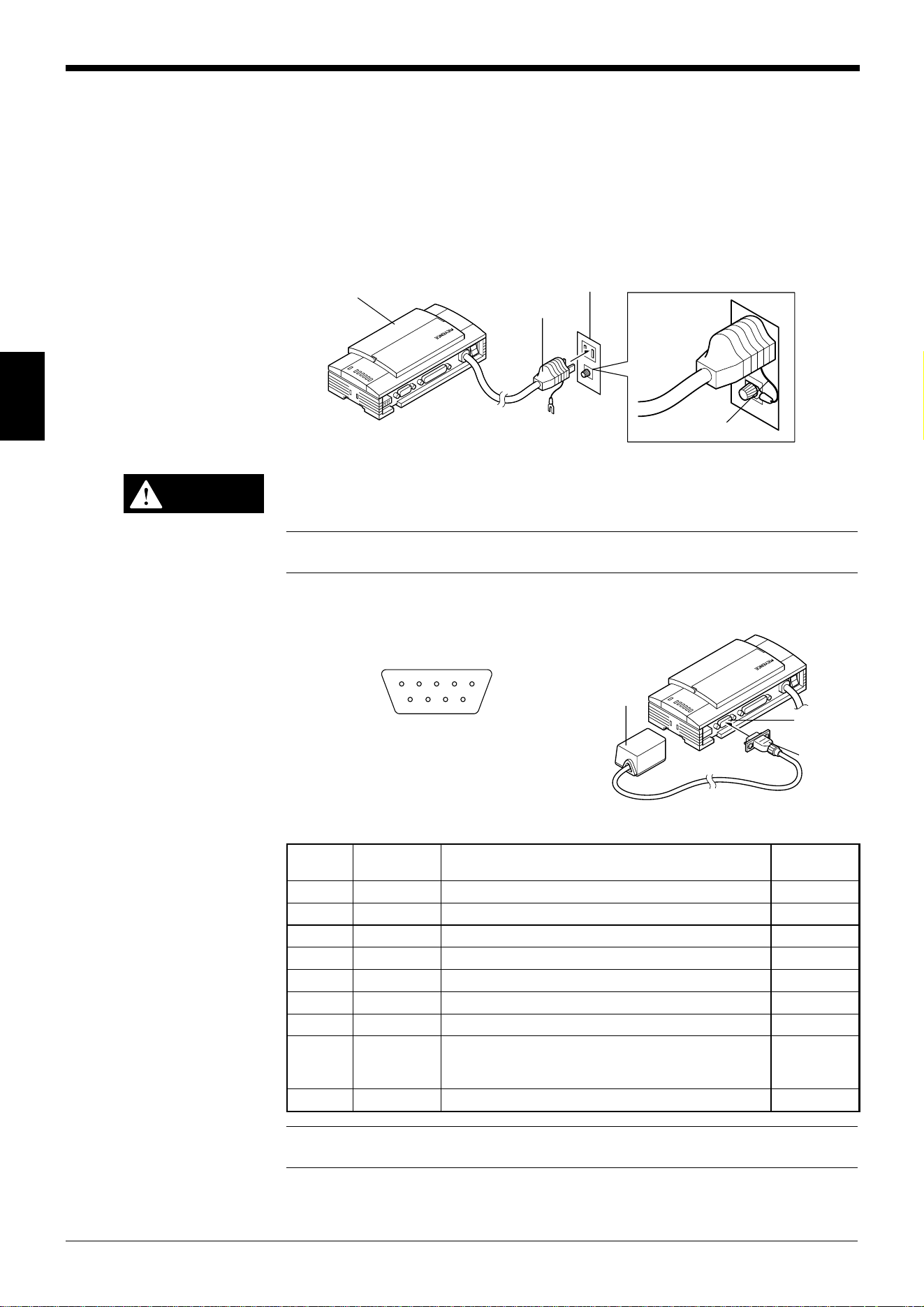
3.1 Connecting BL-U1 and Wiring
This section describes the connection and wiring of the BL-600 Series and periph-
eral devices when the special power supply unit BL-U1 is used.
3.1.1 Connecting the BL-U1, AC power supply, and BL-600 Series
1. Plug the BL-U1 power cable into an outlet.
Do not use a power supply other than 100 to 240 V AC (50/60 Hz).
An improper power supply may cause product failure.
Note: If the noise conveyed through the FG line causes an LB-600 Series reading
error, do not connect the FG line.
2. Connect the BL-600 Series to the READER port of the BL-U1.
■ BL-U1 READER port pin assignment
Note: Do not extend the power cable. A long power cable can cause a voltage
drop, preventing the BL-600 from starting properly.
BL-U1
FG line
Outlet
Power plug
CAUTION
BL-600 Series
Connector
READER
port
21345
6789
D-sub 9-pin (male)
DCE specification (defined as terminal)
#4-40 screw (female)
.oNniPlobmySnoitcnuF
langiS
noitcerid
1MITtupnireggirTtuptuO
2)DXR(DR.atadC232-SRsdneStuptuO
3)DXT(DS.atadC232-SRsevieceRtupnI
4KOKOtupnI
5)GS(DNG)langisevitcepserrofdnuorgnommoC(dnuorG––
6GNGNtupnI
7)STR(SR.atadC232-SRdnesotydaeRtupnI
8)STC(SC
.atadC232-SRdnesottseuqeR
PIDehthtiwdetcelesebnacdohtemlortnoC(
).sehctiws ➮
.71egapeeS
tuptuO
9V5+ylppusrewopV5+tuptuO
Chapter 3 Connection and Installation
17
3
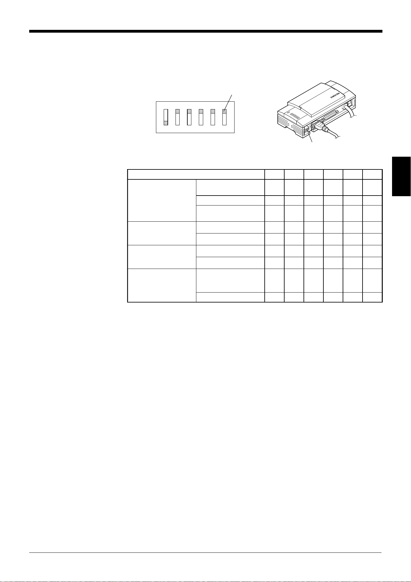
3.1.2 DIP switch setting
Change the DIP switch setting according to the type of communication and termi-
nator setting.
■ DIP switch
OFF
ON
123456
Switch
DIP switch
* The figure above shows the factory-settings.
.oNhctiwSPID 123456
epytnoitacinummoC
noitceles
C232-SR
)gnittes-yrotcaF(
NOFFOFFO
A224-SRFFONOFFO
584-SR
)knilpord-itluM(
FFOFFONO
rotanimretA224-SR
noitanimreT(
001:ecnatsiser Ω)
FFOFFO
NONO
rotanimret584-SR
noitanimreT(
001:ecnatsiser Ω)
FFOFFO
NONO
REDAERfonoitceleS
dohtemlortnocSCtrop
gnidroccaFFOroNO
tropC232-SRehtot
.sutatslangisSC
FFO
NOyllamroNNO
Chapter 3 Connection and Installation
18
3
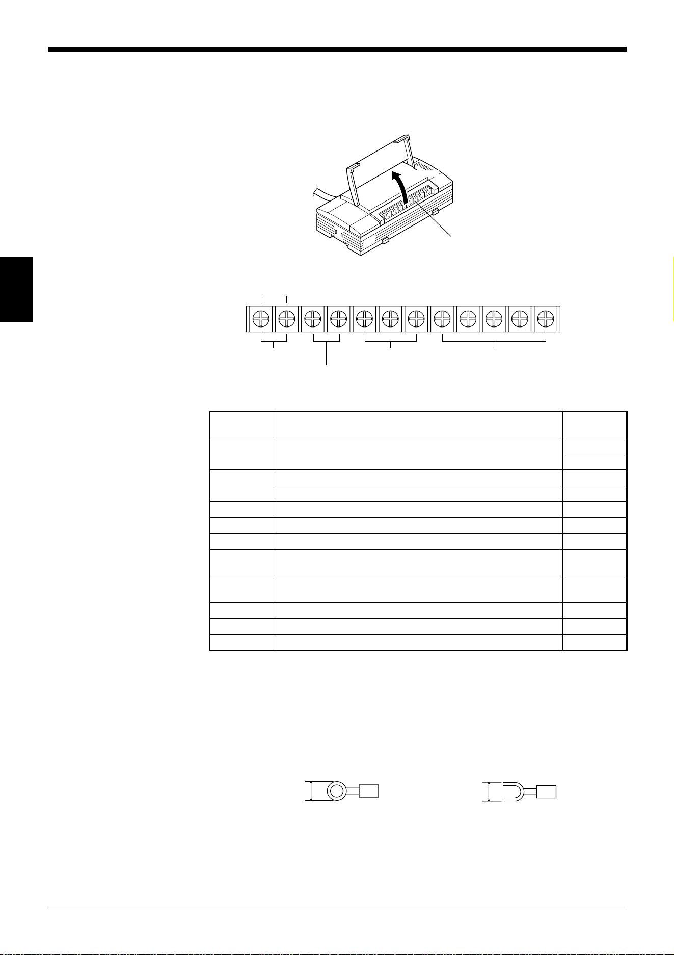
3.1.3 Terminals of I/O terminal block and wiring
Terminals of the I/O terminal block
The terminals of the I/O terminal block are assigned as shown in the figure.
■ Terminal assignment
Applicable crimp terminals
M3.0 screws are used for the terminal block.
Use the following crimp terminal for connection.
■ Shape of applicable crimp terminal
I/O terminal block
Open
TIM
+
12V OUT
-
COM OK NG SDA SDB SG RDA RDB
Trigger input
RS-422A/RS-485
OK/NG output
Power supply for the
sensor (12 V DC, 300 mA)
lobmySnoitpircseD
langiS
noitcerid
MITtupnireggirT
tupnI
tupnI
-TUOV21+
)Am003,CDV21(rosnesrofylppusrewopfolanimret+tuptuO
)V0(rosnesrofylppusrewopfolanimret– tuptuO
MOCtuptuoGN/KOroflanimretnommoC —
KOtuptuoKOtuptuO
GNtuptuoGNtuptuO
ADS lanimret+584-SR/noissimsnartatadA224-SRroflanimret+
,tuptuO
tuptuO/tupnI
BDSlanimret-584-SR/noissimsnartatadA224-SRroflanimret–
,tuptuO
tuptuO/tupnI
GSdnuorglangiS —
ADRnoitpeceratadA224-SRroflanimret+tupnI
BDRnoitpeceratadA224-SRroflanimret– tupnI
6.0 mm or
less
Round-shape
6.0 mm or
less
Fork-shape
Chapter 3 Connection and Installation
19
3
Connecting trigger input
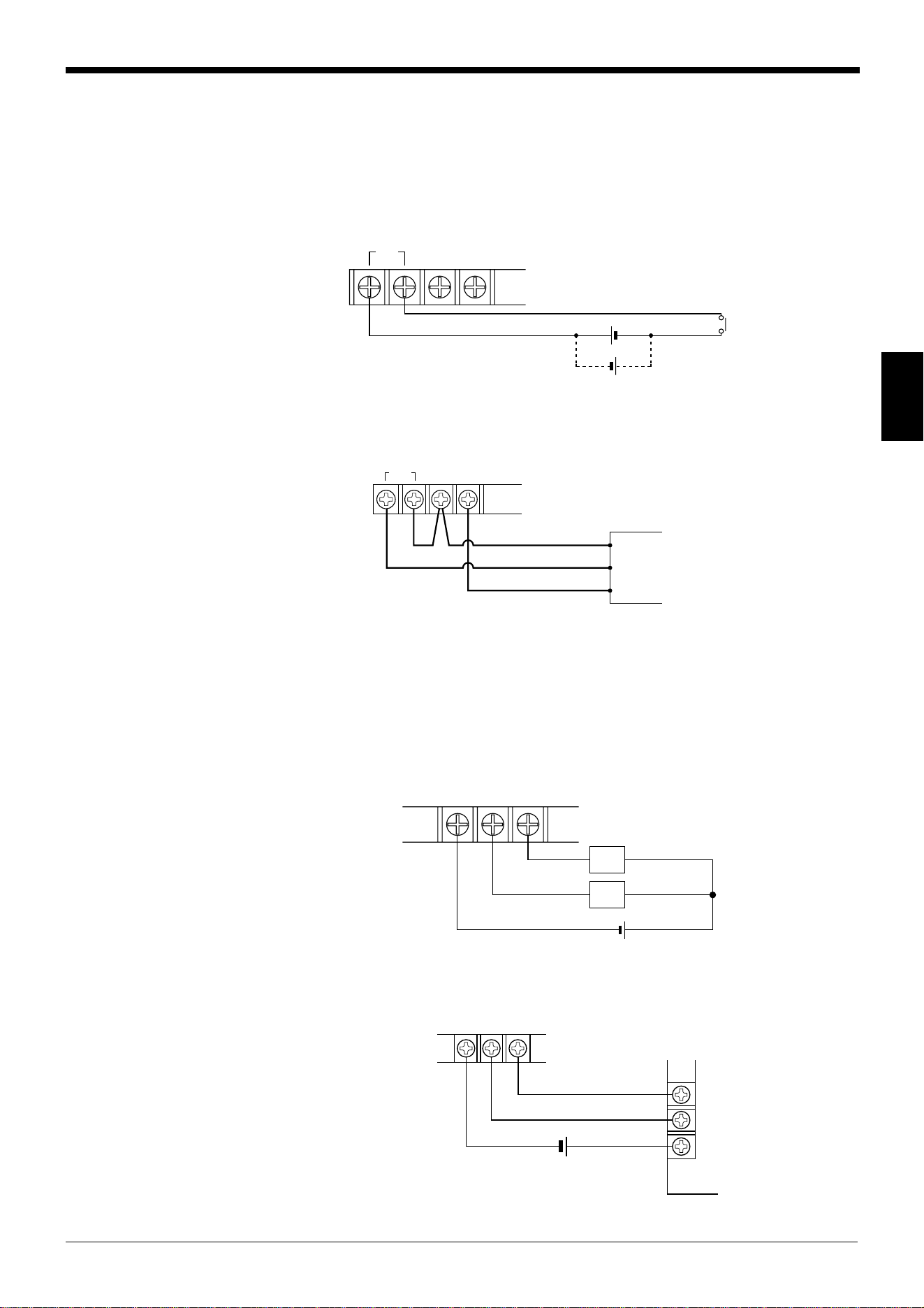
The trigger input allows the BL-600 Series to start reading bar codes (turn on the
laser beam).
The trigger input is turned ON when 8.5 to 30 V DC input is activated between the
trigger input terminals.
The BL-U1’s power supply terminals for the sensor can be used as the power
supply input for the sensor.
■ Connection to a photoelectric sensor manufactured by KEYENCE
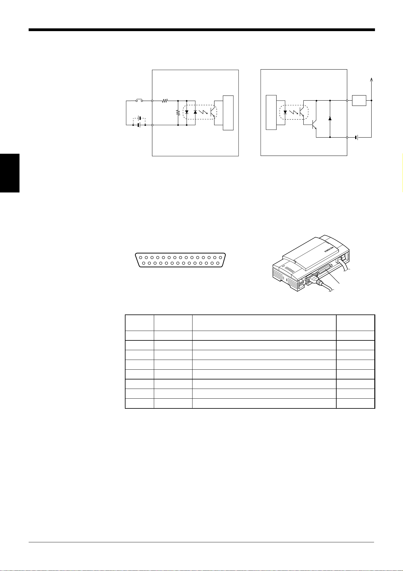
Connecting the OK/NG output
The OK/NG output is used to differentiate between acceptable and unacceptable
results based on a comparison with preset data
(
➮
See pages 101.)
. It can also be
used to indicate whether or not the BL-600 Series successfully reads bar codes
when there is no preset data entered.
The OK/NG output is an NPN open-collector output.
■ Connection to a programmable logic controller (PLC) manufactured by
KEYENCE
TIM +12 V OUT–
8.5 to 30 V DC
+
+
Contact or
solid-state
+
12 V OUT
–
TIM
Photoelectric sensor
Brown (Red)
Black (White)
Blue (Black)
COM OK NG
Load
Load
+
*Rated load: 30 V DC max. (100 mA)
0001
0000
C
COM OK NG
+
PLC
Chapter 3 Connection and Installation
20
3
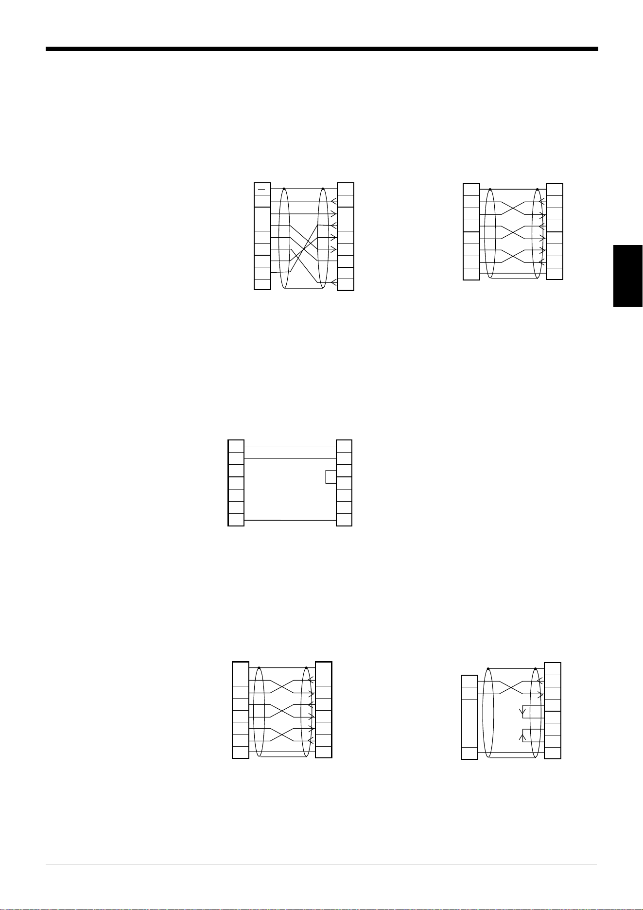
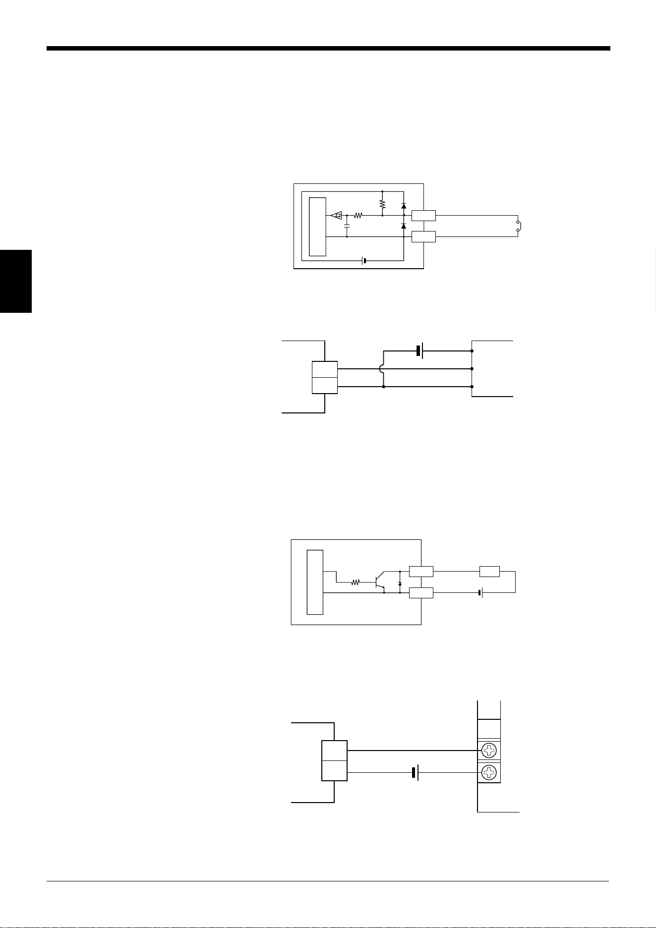
I/O circuit diagram
■ Input circuit diagram ■ Output circuit diagram
3.1.4 Connecting RS-232C
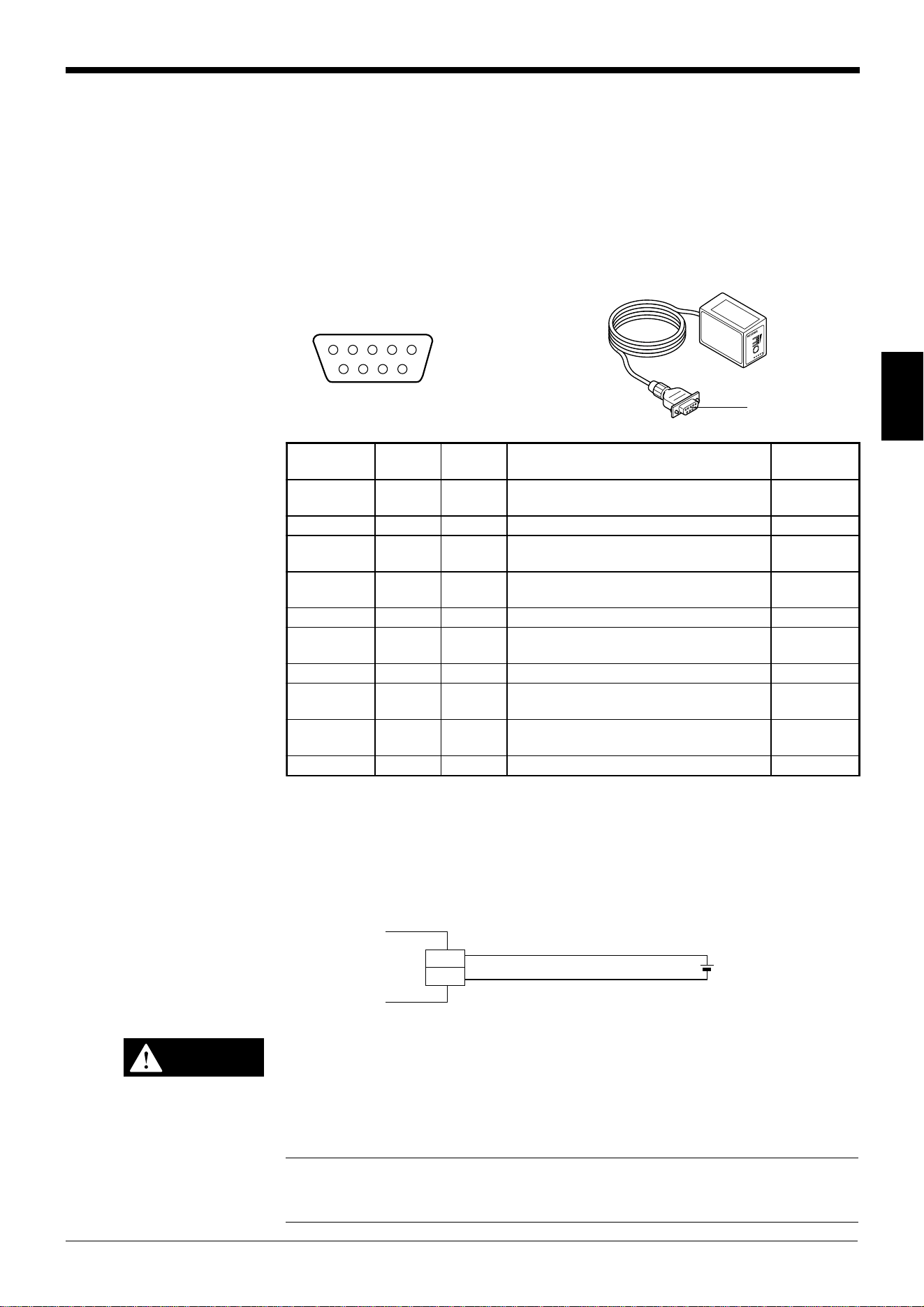
Pin assignment of the RS-232C port
The BL-U1 has a RS-232C port with the following pin assignment.
■ RS-232C port pin assignment
TIM
2.4
kΩ
3.3 kΩ
Internal circuit
+
+
Load
OK/NG
COM
+
Internal circuit
13 1
25 14
RS-232C port
D-sub 25-pin (female)
DTE specification (defined as terminal)
M2.6 screw (female)
.oNniPlobmySnoitcnuF
langiS
noitcerid
1GFdnuorgemarF —
2)DXT(DSatadC232-SRsdneStuptuO
3)DXR(DRatadC232-SRsevieceRtupnI
4)STR(SR)NOsyawla(atadC232-SRdnesottseuqeRtuptuO
5)STC(SCatadC232-SRdnesotydaeRtupnI
6)RSD(RD.edisni02.oNnipotdetcennoCtupnI
7)GS(DNGdnuorglangiS —
02)RTD(RE.edisni6.oNnipotdetcennoCtuptuO
Chapter 3 Connection and Installation
21
3
Wiring the RS-232C cable
Connect the BL-U1 to a personal computer or other devices with the following
wiring.
■ Connecting a PC
9-pin serial port 25-pin serial port
■ Connecting NEW KV Series/Communication port
KV-10/16/24/40
■ Connecting KV-L2*
Port 1 Port 2
2
PC
SD
CD
RD
RS
CS
DR
SG
ER
3
4
5
6
2
1
BL-U1
SD
FG
RD
SG
RS
CS
DR
ER
3
4
5
6
7
8
7
8
201
D-sub 25-pin (male)
M2.6 screw
Connector case
D-sub 9-pin (female)
#4-40 screw
2
PC
SD
RD
RS
CS
DR
ER
SG
3
4
5
6
2
11
BL-U1
SD
FGFG
RD
RS
CS
DR
ER
SG
3
4
5
6
20
7
20
7
D-sub 25-pin (male)
M2.6 screw
D-sub 25-pin (male)
M2.6 screw
* KEYENCE option OP-22149 (1.5 m)
or commercially available cross cable
can be used.
* KEYENCE option OP-22149 (1.5 m)
and OP-25057 (conversion connec-
tor) can be used.
5
3
4
3
2
4
5
6
20
7
BL-U1Communication port
D-sub 25-pin (male)
M2.6 screw
RJ11
RD
SD
SG
RD
RS
SD
CS
DR
ER
SG
* KEYENCE option OP-96368 (2.5 m)
and OP-96369 (conversion connec-
tor) can be used.
2
KV-L2
SD
RD
RS
CS
DR
ER
SG
3
4
5
6
2
11
BL-U1*
SD
FGFG
RD
RS
CS
DR
ER
SG
3
4
5
6
20
7
20
7
D-sub 25-pin (male)
M2.6 screw
D-sub 25-pin (male)
M2.6 screw
3
KV-L2
SD
RD
SG
5
2
1
BL-U1*
SD
FG
RD
RS
CS
DR
ER
SG
3
4
5
6
20
71
D-sub 25-pin (male)
M2.6 screw
Terminal block
* KEYENCE option OP-22149 (1.5 m) or
commercially available cross cable can be
used.
Chapter 3 Connection and Installation
22
3
2
PLC
SD
RD
RS
CS
SG
3
4
5
9
2
11
BL-U1*
SD
FGFG
RD
RS
CS
SG
3
4
5
7
D-sub 25-pin (male)
M2.6 screw
D-sub 9-pin (male)
M2.6 screw
■ Connecting MELSEC-A Series
Connection with AJ71(U)C24(-S■), Connection with A1SJ71(U)C24-R2/PRF,
AJ71QC24-R2, A2CCPUC24(-PRF)
A0J2-C214-S1
■ SYSMAC-C Series
Connection with C200H-LK201(-V1), Connection with C20H,
C500-LK203, C28H,
C500-LK201-V1, C40H
C120-LK201-V1
Connection with C200HS-CPU21/23/31/33,
CQM1-CPU21/41/42/43/44,
C200HE-CPU32/42,
C200HG-CPU33/43/53/63,
C200HW-COM02/COM04/COM05/COM06
C200HX-CPU34/44/54/64,
C200HX-CPU65-Z/85-Z
2
Link unit
SD
RD
RS
CS
DR
SG
ER
3
4
5
6
2
11
BL-U1*
SD
FGFG
RD
RS
CS
DR
SG
ER
3
4
5
6
7
20
7
20
CD
88
D-sub 25-pin (male)
M2.6 screw
D-sub 25-pin (male)
M2.6 screw
2
Link unit
RD
SD
ER
SG
DR
RS
CD
3
4
5
6
2
1–
BL-U1*
SD
FGConnector case
RD
RS
CS
DR
SG
ER
3
4
5
6
7
20
7
1
CS
88
D-sub 25-pin (male)
M2.6 screw
D-sub 9-pin (male)
M2.6 screw
2
Link unit
SD
RD
RS
CS
SG
3
4
5
7
2
11
BL-U1*
SD
FGFG
RD
RS
CS
SG
3
4
5
7
D-sub 25-pin (male)
M2.6 screw
D-sub 25-pin (male)
M2.6 screw
2
PLC
SD
RD
RS
CS
SG
3
4
5
7
2
11
BL-U1*
SD
FGFG
RD
RS
CS
SG
3
4
5
7
D-sub 25-pin (male)
M2.6 screw
D-sub 9-pin (male)
M2.6 screw
* KEYENCE option OP-22149 (1.5 m) or
commercially available cross cable can be
used.
Chapter 3 Connection and Installation
23
3
■ SYSMAC-CV Series
Connection with CV500-LK201(Port 1) Connection with CV500-LK201 (Port 2),
CV500,
CV1000,
CVM1
3.1.5 Wiring the RS-422A
Note 1: The cable can be extended to within 1.2 km.
Note 2: Turn ON the terminators (BL-U1/external unit terminal resistance: 100 Ω).
➮
See page 17
.
Connect the BL-U1 to other devices with the following wiring.
■ Connecting a general RS-422A unit
Use the same wiring when connecting the BL-U1 to the BL-U1*.
■ Connecting the MELSEC-A Series
Connecting with AJ71(U)C24(-S■),
AJ71QC24-R4,
A0J2-C214-S1,
A1SJ71(U)C24-R4
2
Link unit
SD
RD
RS
CS
SG
3
4
5
7
2
11
BL-U1*
SD
FGFG
RD
RS
CS
SG
3
4
5
7
D-sub 25-pin (male)
M2.6 screw
D-sub 25-pin (male)
M2.6 screw
2
PLC
SD
RD
RS
CS
SG
3
4
5
9
2
11
BL-U1*
SD
FGFG
RD
RS
CS
SG
3
4
5
7
D-sub 25-pin (male)
M2.6 screw
D-sub 9-pin (male)
M2.6 screw
* KEYENCE option OP-22149 (1.5 m) or
commercially available cross cable can be
used.
SDA
SG
BL-U1*
SDB
RDA
RDB
RD + (RDA)
SG
External unit
BL-U1*
RD – (RDB)
SD + (SDA)
SD – (SDB)
Twisted pair cable
SDA
SG
BL-U1*
SDB
RDA
RDB
RDA
SG
Link unit
RDB
SDA
SDB
Twisted pair cable
Chapter 3 Connection and Installation
24
3
SDA
SG
BL-U1*
SDB
RDA
RDB
Link unit
1RDB
RDA
SDB
SDA
FG
6
5
9
7
3
SG
D-sub 9-pin (male)
M2.6 screw
Twisted pair cable
SDA
SG
BL-U1*
SDB
RDA
RDB
8RDB
RDA
SDB
SDA
6
2
1
9
SG
D-sub 9-pin (male)
M2.6 screw
Twisted pair cable
Communication
board
SDA
SG
BL-U1*
SDB
RDA
RDB
PLC
8RDB
RDA
SDB
SDA
RS
CS
6
2
1
4
9
SG
5
D-sub 9-pin (male)
M2.6 screw
Twisted pair cable
■ Connecting SYSMAC-C Series
Connecting with C200H-LK202 (-V1), Connecting with C200HW-COM03/COM06
C500-LK201-V1,
C500-LK203,
C120-LK202-V1
■ Connecting SYSMAC-CV Series
Connecting with CV-500-LK201,
CV500,
CV1000,
CVM1
Chapter 3 Connection and Installation
25
3
3.2 Connecting the BL-U2/N-42 and Wiring
This section describes the connection and wiring of the BL-600 Series and periph-
eral devices when the special power supply unit BL-U2 or N-42 is used.
3.2.1 Connecting the BL-U2/N-42, AC power supply, and BL-600 Series
1. Connect the 24 V DC power supply to the power supply terminals of the BL-U2
or N-42.
BL-U2 N-42
Power supply terminals Power supply terminals
Make sure that the power supply provides 24 V DC. If the power supply
output is not 24 V DC, it can damage the unit.
Note: If the power supply is UL rated, it must provide Class 2 output.
2. Connect the BL-600 Series to the READER port of the BL-U2 or N-42.
BL-U2 N-42
P
O
W
E
R
S
D
R
D
R
EA
D
E
R
R
S
-2
3
2C
T
E
R
M
I
N
A
T
O
R
O
N
O
F
F
P
O
W
E
R
S
D
R
D
R
E
A
D
E
R
Power supply
terminals
Power supply
terminals
+
+-
24V DC
24V DC IN
+
+-
24V DC
24V DC IN
N.C.N.C.N.C.
CAUTION
BL-600 Series
Connector
READER port
BL-600 Series
Connector
READER port
Chapter 3 Connection and Installation
26
3
■ BL-U2/N-42 READER port pin assignment
Note: Do not extend a power cable. A long power cable can cause a voltage drop,
preventing the BL-600 from starting properly.
3.2.2 Terminals of I/O terminal block and connections
Terminals of the I/O terminal block
The terminals of the I/O terminal block are assigned as shown in the figure.
■ Terminal assignment
BL-U2 N-42
Applicable terminals
Use the following solderless contact pin (I-terminal) for connection.
Recommended product
Manufacturer: Japan Solderless Terminal (J.S.T.) Mfg. Co., Ltd.
Model: VTUB-1.25
21345
6789
D-sub 9-pin (male)
DCE specification (defined as terminal)
#4-40 screw (female)
.oNniPlobmySnoitcnuF
langiS
noitcerid
1MITtupnireggirTtuptuO
2)DXR(DRatadC232-SRsdneStuptuO
3)DXT(DSatadC232-SRsevieceRtupnI
4KOlangisKOtupnI
5)GS(DNG)langisevitcepserrofdnuorgnommoC(dnuorG —
6GNlangisGNtupnI
7)STR(SRatadC232-SRdnesotydaeRtupnI
8)STC(SCatadC232-SRdnesottseuqeRtuptuO
9V5+ylppusrewopV5+tuptuO
TIM OK NG
COM COM
P
O
W
E
R
S
D
R
D
R
E
A
D
E
R
R
S
-2
32C
T
E
R
M
I
N
A
T
O
R
O
N
O
F
F
P
O
W
E
R
S
D
R
D
R
E
A
D
E
R
Trigger input
I/O terminal block
OK/NG
output
I/O terminal block
5 mm max.
6 mm min
2.0 mm
max.
lobmySnoitpircseDnoitceridlangiS
MITtupnireggirTtupnI
MOCtupnireggirtroflanimretnommoCtupnI
KOtuptuoKOtuptuO
GNtuptuoGNtuptuO
MOCtuptuoroflanimretnommoCtuptuO
Chapter 3 Connection and Installation
27
3
Connecting trigger input
The trigger input allows the BL-600 to start reading bar codes (turn on the laser
beam). To turn ON the trigger input, supply 15 to 26 V DC between the trigger input
terminals.
■ Connection to a photoelectric sensor manufactured by KEYENCE
Connecting the OK/NG output
The OK/NG output is used to differentiate between acceptable and unacceptable
results based on a comparison with preset data.
(
➮
See page 101.)
It can also be used
to indicate whether or not the BL-600 Series successfully reads bar codes when
there is no preset data entered.
The OK/NG output is an NPN open-collector output.
■ Connection to a programmable logic controller (PLC) manufactured by
KEYENCE
15 to 26 V DC
+
+
TIM
BL-U2, N-42
COM
OK
Contact or
solid-state
Circuit diagram
TIM
COM
Internal circuit
+
+
TIM
COM
OK
+
Photoelectric sensor
BL-U2, N-42
Brown (Red)
Black (White)
Blue (Black)
+
COM
OK NG
Load
Load
Internal circuit
+
Load
OK/NG
COM
0001
0000
C
COM
OK NG
+
PLC
Circuit diagram
BL-U2, N-42
BL-U2, N-42
* Rated load: 30V DC max.
(100 mA)
Chapter 3 Connection and Installation
28
3
5
3
4
3
2
4
6
7
8
5
BL-U2
RD
SD
SG
SD
ER
RD
DR
RS
CS
SG
D-sub 9-pin (female)
#4-40 screw
Communication port
RJ11
* KEYENCE option OP-96368 (2.5 m)
and OP-96369 (conversion connector)
can be used.
3.2.3 Connecting RS-232C (BL-U2)
Pin assignment of the RS-232C port
The BL-U1 has a RS-232C port with the following pin assignment.
■ RS-232C port pin assignment
* One connector is provided.
Wiring the RS-232C cable
Connect the BL-U1 to a personal computer or other devices with the following
wiring.
■ Connecting a PC
9-pin serial port 25-pin serial port
■ Connecting NEW KV Series/Communication port
KV-10/16/24/40
D-sub 9-pin (male)
DTE specification
(defined as terminal)
#4-40 screw (female)
21345
6789
POWER
SD
RD
READER
RS-232C
RS-232C port
.oNniPlobmySnoitcnuF
langiS
noitcerid
2)DXR(DRatadevieceRtupnI
3)DXT(DSataddneStuptuO
4)RTD(RE.edisni6.oNnipotdetcennoCtuptuO
5GSdnuorglangiS —
6)RSD(RD.edisni4.oNnipotdetcennoCtupnI
7)STR(SR)NOsyawla(ataddnesottseuqeRtuptuO
8)STC(SCataddnesotelbanEtupnI
2
PC
SD
RD
DR
SG
ER
CS
RS
3
7
8
4
2
BL-U2
RD
Connector case
SD
DR
SG
RS
CS
ER
3
7
8
4
6
5
6
5
D-sub 9-pin (female)
#4-40 screw
D-sub 9-pin (female)
#4-40 screw
Connector case
2
PC
RD
SD
FG
ER
SG
DR
CS
RS
3
4
5
6
2
1
BL-U2
RD
Connector case
SD
DR
SG
RS
CS
ER
3
7
8
4
6
5
20
7
D-sub 25-pin (male)
M2.6 screw
D-sub 9-pin (female)
#4-40 screw
* KEYENCE option OP-22149 (1.5 m)
or OP-25057 (conversion connector)
can be used.
* KEYENCE option cable OP-27937 (2 m)
can be used.
Chapter 3 Connection and Installation
29
3
■ Connecting KV-L2*
Port 1 Port 2
■ Connecting MELSEC-A Series
Connection with AJ71(U)C24(-S■), Connection with A1SJ71(U)C24-R2/PRF,
AJ71QC24-R2, A2CCPUC24(-PRF)
A0J2-C214-S1
2
KV-L2*
RD
SD
FG
ER
SG
DR
CS
RS
3
4
5
6
2
1
BL-U2
RD
Connector case
SD
DR
SG
RS
CS
ER
3
7
8
4
6
5
20
7
D-sub 25-pin (male)
M2.6 screw
D-sub 9-pin (female)
#4-40 screw
3
KV-L2*
SD
RD
SG
5
2
BL-U1*
RD
SD
RS
CS
ER
DR
SG
3
7
8
4
6
51
D-sub 9-pin (female)
#4-40 screw
Terminal block
Connector case
* KEYENCE option OP-22149 (1.5 m) and
OP-25057 (conversion connector) can
be used.
2
Link unit
SD
RD
RS
CS
DR
SG
ER
3
4
5
6
2
1
BL-U2
RD
FG
SD
RS
CS
ER
SG
DR
3
7
8
4
57
20
CD
68
D-sub 25-pin (male)
M2.6 screw
Connector case
D-sub 9-pin (female)
#4-40 screw
2
Link unit
RD
SD
RS
CS
ER
DR
CD
3
7
8
4
2
BL-U2
RD
SD
RS
CS
ER
DR
SG
3
7
8
4
66
1
SG
55
D-sub 9-pin (male)
M2.6 screw
Connector caseConnector case
D-sub 9-pin (female)
#4-40 screw
Chapter 3 Connection and Installation
30
3
■ SYSMAC-C Series
Connection with C200H-LK201(-V1), Connection with C20H,
C500-LK203, C28H,
C500-LK201-V1, C40H
C120-LK201-V1
Connection with C-200HS-CPU21/23/31/33,
CQM1-CPU21/41/42/43/44,
C-200HE-CPU32/42,
C200HG-CPU33/43/53/63,
C200HW-COM02/COM04/COM05/COM06
C200HX-CPU34/44/54/64,
C200HX-CPU65-Z/85-Z
■ SYSMAC-CV Series
Connection with CV500-LK201(Port 1) Connection with CV500-LK201 (Port 2),
CV500,
CV1000,
CVM1
2
Link unit
SD
RD
RS
CS
SG
3
4
5
7
2
1
BL-U2
RD
FG
SD
RS
CS
SG
3
7
8
5
D-sub 25-pin (male)
M2.6 screw
Connector case
D-sub 9-pin (female)
#4-40 screw
2
PLC
SD
RD
RS
CS
SG
3
4
5
7
2
1
BL-U2
RD
FG
SD
RS
CS
SG
3
7
8
5
D-sub 9-pin (male)
M2.6 screw
Connector case
D-sub 9-pin (female)
#4-40 screw
* KEYENCE option OP-22149 (1.5 m) and
OP-25057 (conversion connector) can
be used.
2
PLC
SD
RD
RS
CS
SG
3
4
5
9
2
1
BL-U2
RD
FG
SD
RS
CS
SG
3
7
8
5
D-sub 9-pin (male)
M2.6 screw
Connector case
D-sub 9-pin (female)
#4-40 screw
2
Link unit
SD
RD
RS
CS
SG
3
4
5
7
2
1
BL-U2
RD
FG
SD
RS
CS
SG
3
7
8
5
D-sub 25-pin (male)
M2.6 screw
Connector case
D-sub 9-pin (female)
#4-40 screw
2
PLC
SD
RD
RS
CS
SG
3
4
5
9
2
1
BL-U2
RD
FG
SD
RS
CS
SG
3
7
8
5
D-sub 9-pin (male)
M2.6 screw
Connector case
D-sub 9-pin (female)
#4-40 screw
* KEYENCE option OP-22149 (1.5 m) and
OP-25057 (conversion connector) can
be used.
Chapter 3 Connection and Installation
31
3
3.2.4 Connecting the N-42 to RS-422A
RS-422 terminal block assignment
The terminals of the RS-422A terminal block of the N-42 are assigned as shown in
the figure.
■ RS-422 terminal block assignment
Note 1: The cable can be extended to within 1.2 km.
Note 2: Turn ON the terminators (BL-U1/external unit terminal resistance: 100 Ω).
Wiring the RS-422A
Connect the N-42 to other devices with the following wiring.
■ Connecting a general RS-422A unit
Use the same wiring when connecting the N-42 to the N-42.
RS-422
SG SD+ RD+SD– RD–
T
E
R
M
I
N
A
T
O
R
O
N
O
F
F
P
O
W
E
R
S
D
R
D
R
E
A
D
E
R
RS-422
terminal block
edoCnoitpircseDnoitceridlangiS
GSdnuorG —
+DS.lanimret+otatadsdneStuptuO
-DS.lanimret-otatadsdneStuptuO
+DR.lanimret+morfatadsevieceRtupnI
-DR.lanimret-morfatadsevieceRtupnI
TERMINATOR
ON
OFF
[ON]
SD +
SG
N-42
External unit
(N-42)
SD –
RD +
RD –
RD +
SG
RD –
SD +
SD –
Twisted pair cable
Chapter 3 Connection and Installation
32
3
■ Connecting the MELSEC-A Series ■ Connecting SYSMAC-C Series
Connecting with AJ71(U)C24(-S■), Connecting with C200H-LK202 (-V1),
AJ71QC24-R4, C500-LK201-V1,
A0J2-C214-S1, C500-LK203,
A1SJ71(U)C24-R4 C120-LK202-V1
■ Connecting SYSMAC-C Series ■ Connecting SYSMAC-CV Series
Connecting with C200HW-C0M03/CPM06 Connecting with CV-500-LK201,
CV500,
CV1000,
CVM1
SD+
SG
N-42
SD–
RD+
RD–
RDA
SG
Link unit Twisted pair cable
RDB
SDA
SDB
SD+
SG
N-42
SD–
RD+
RD–
Link unit Twisted pair cable
1RDB
RDA
SDB
SDA
FG
6
5
9
7
3
SG
D-sub 9-pin (male)
M2.6 screw
SD+
SG
N-42Twisted pair cable
Communication
board
SD–
RD+
RD–
8RDB
RDA
SDB
SDA
6
2
1
9
SG
D-sub 9-pin (male)
M2.6 screw
SD+
SG
N-42
SD–
RD+
RD–
PLC Twisted pair cable
8RDB
RDA
SDB
SDA
RS
CS
6
2
1
4
9
SG
5
D-sub 9-pin (male)
M2.6 screw
Chapter 3 Connection and Installation
33
3
3.3 Wiring without the Special Power Supply Units
This section describes the connection and wiring of the BL-600 Series and periph-
eral devices when a special power supply unit is not used.
3.3.1 Pin assignments of the BL-600 Series connector and the connecting
power supply
Pin assignment of the BL-600 Series power supply connector
■ Connector pin assignment
Power supply connections
Connect the 5 V DC power supply to the power supply connector of the BL-600
Series.
• Be sure to match the polarities of the power supply when soldering the
connections. Reversing the polarities will damage the unit.
• Make sure that the power supply provides a stable 5 V DC
±
5%. If the
power supply does not function in the above range, it can damage the
unit.
Note1: Do not extend the power cable. A long power cable can cause a voltage
drop, preventing the BL-600 from starting properly.
Note2: If the power supply is UL rated, it must provide Class 2 output.
54 321
9876
D-sub 9-pin
(female)
#4-40 screw (male)
LASER ON
O
K
/
N
G
TIMING
T
E
ST
Connector
.oNniP
elbaC
roloc
lobmySnoitpircseD
langiS
noitcerid
rotcennoC
esac
dleihSGFdnuorgemarF —
1wolleYMITtupnireggirTtupnI
2nworB
DR
)DXR(
atadC232-SRsevieceRtupnI
3elpruP
DS
)DXT(
atadC232-SRsdneStuptuO
4etihWKOtuptuoKOtuptuO
5kcalB
DNG
)GS(
evitcepserrofdnuorgnommoC(dnuorG
)slangis
—
6yarGGNtuptuoGNtuptuO
7kniP
SR
)STR(
syawla(atadC232-SRdnesottseuqeR
)NO
tuptuO
8eulB
SC
)STC(
C232SRhguorhtataddnesotelbanEtupnI
9deRV5+ylppusrewopV5+tupnI
5 V DC
BL-600
+5V
9
GND
5
+
CAUTION
Chapter 3 Connection and Installation
34
3
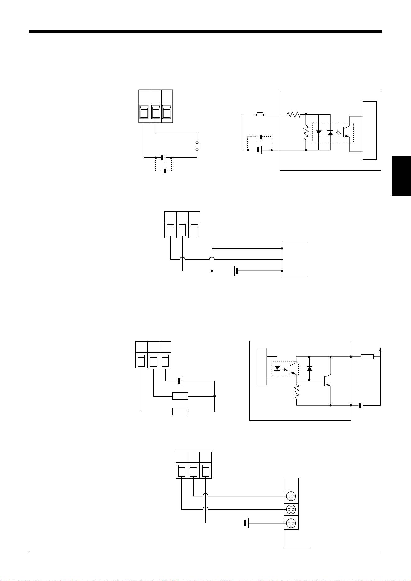
3.3.2 I/O Wiring
Trigger input
The trigger input is used to signal the BL-600 to start reading (start laser emission).
The trigger input is a non-voltage input (TTL input is also available with negative
logic).
■ Connection to a photoelectric sensor manufactured by KEYENCE
OK/NG output
The OK/NG output is used to display the comparison/verification result of the
preset data. ➮
See page 101.
When no preset data is registered, it can be used to display whether or not bar
codes are being read correctly. The output form is NPN open-collector.
■ Connection to a programmable logic controller (PLC) manufactured by
KEYENCE
GND
TIM
1
5
5 V DC
10 kΩ
4.7
kΩ
Internal circuit
BL-600
Contact or
solid-state
Circuit diagram
TIM
GND
+
1
5
BL-600
Photoelectric sensor
Brown (Red)
Black (White)
Blue (Black)
GND
OK/NG
4/6
5
Load
BL-600
10 kΩ
* Rated load: 24 V DC
(30 mA) max.
+
Internal circuit
Circuit diagram
OK/NG
GND
+
4/6
BL-600
5
0000
C
PLC

Chapter 3 Connection and Installation
35
3
2
3
7
8
5
9
PC
SD
RD
RS
CS
GND
+5V
3
2
8
7
5
4
6
SD
RD
CS
RS
SG
ER
DR
+
BL-600
D-sub 9-pin (female)
# 4-40 screw
D-sub 9-pin (male)
# 4-40 screw
3
2
8
7
5
9
BL-600
SD
CS
RS
GND
+5V
PC
2
3
4
7
6
5
20
SDRD
RD
RS
CS
SG
DR
ER
D-sub 25-pin (male)
M2.6 screw
D-sub 9-pin (male)
# 4-40 screw
3.3.3 RS-232C connection
Wire the RS-232C as indicated below when connecting the BL-600 to a PC.
Connecting the computer with 9-pin Connecting the computer with 25-pin


Chapter 4
Setup Software
This chapter describes the usage of the setup software to set or perform reading
tests of the BL-600 Series.
4.1 Installing and Operating the Setup Software .................... 38
4.1.1 Installation and operation procedures.................................... 38
4.1.2 Installing setup software ........................................................ 39
4.1.3 Installation/Start-up ................................................................ 39
4.1.4 Initial screen........................................................................... 40
4.1.5 Basic operation ...................................................................... 41
4.2 Setup Procedure .................................................................. 42
4.2.1 Model selection ...................................................................... 42
4.2.2 [[Main]] (Operation setting) screen ........................................ 42
4.2.3 [[Comm Settings-1]] (Communication parameters 1) screen .... 45
4.2.4 [[Comm Settings-2]] (Communication parameters 2) screen .... 46
4.2.5 [[Code setup]] (Bar code setting) screen ............................... 49
4.2.6 [[Utility]] screen ...................................................................... 53
4.3 Sending/Receiving Settings ............................................... 54
4.3.1 Sending/receiving settings to/from the BL-600 Series ........... 54
4.3.2 Sending/receiving settings to/from the BL-600 Series
via the N-400 ......................................................................... 57
4.4 Reading/Saving/Printing File .............................................. 59
4.4.1 [[Files] screen ........................................................................ 59
4.4.2 Reading a previously saved setting file ................................. 59
4.4.3 Saving updated settings in a file ............................................ 60
4.4.4 Comparing the contents of the file currently being edited
with a saved file ..................................................................... 61
4.4.5 Printing contents of a setting file ............................................ 61
4.4.6 Resetting the edited settings to the initial (factory) settings... 62
4.5 Using Monitor ....................................................................... 62
4.5.1 Receiving data and checking the result ................................. 62
4.5.2 Command transmission ......................................................... 63
4.5.3 Starting the test mode............................................................ 65
4.5.4 Changing the scanning width................................................. 66
4.6 List of Error Messages ........................................................ 67
4.7 Example of Printing from the Setup Software .................. 68
Chapter 4 Setup Software
38
4
4.1 Installing and Operating the Setup Software
This section describes the installation and operation procedures of the setup
software.
4.1.1 Installation and operation procedures
The following chart shows the installation and setup procedures of the setup
software.
* The shaded boxes indicate an operation of the setup software or a personal
computer.
Check the operating environment. ➮
See page 39.
Install the setup software. ➮
See page 39.
Connect the BL-600 Series to a personal ➮
For the applicable cable
computer with the RS-232C cable.
and wiring, see “3.1
Connecting BL-U1
and Wiring” on page 16
or “3.2 Connecting the
BL-U2 or N-42 and
Wiring” on page 25.
Start the setup software. ➮
See pages 39 to 40.
Select “BL-600” for “Model”. ➮
See page 42.
Specify each item. ➮
See pages 42 to 54.
Press the TEST switch of the BL-600 ➮
See page 54.
Series for 8 seconds.
Send the updated settings to
➮
See page 54.
the BL-600 Series.
* The current settings of
the BL-600 Series can
be read from the PC.
* If the multi-drop link is
established with the
N-400, the settings of
the BL-600 Series can
also be changed via
the N-400.
➮
See pages 57 and 58.
Press the TEST switch of the BL-600 ➮
See page 56.
Series once.
Save or print the settings as required.
➮
See pages 60 and 61.
Quit the setup software. ➮
See page 40
.
➞
➞
➞
➞
➞
➞➞ ➞
➞➞
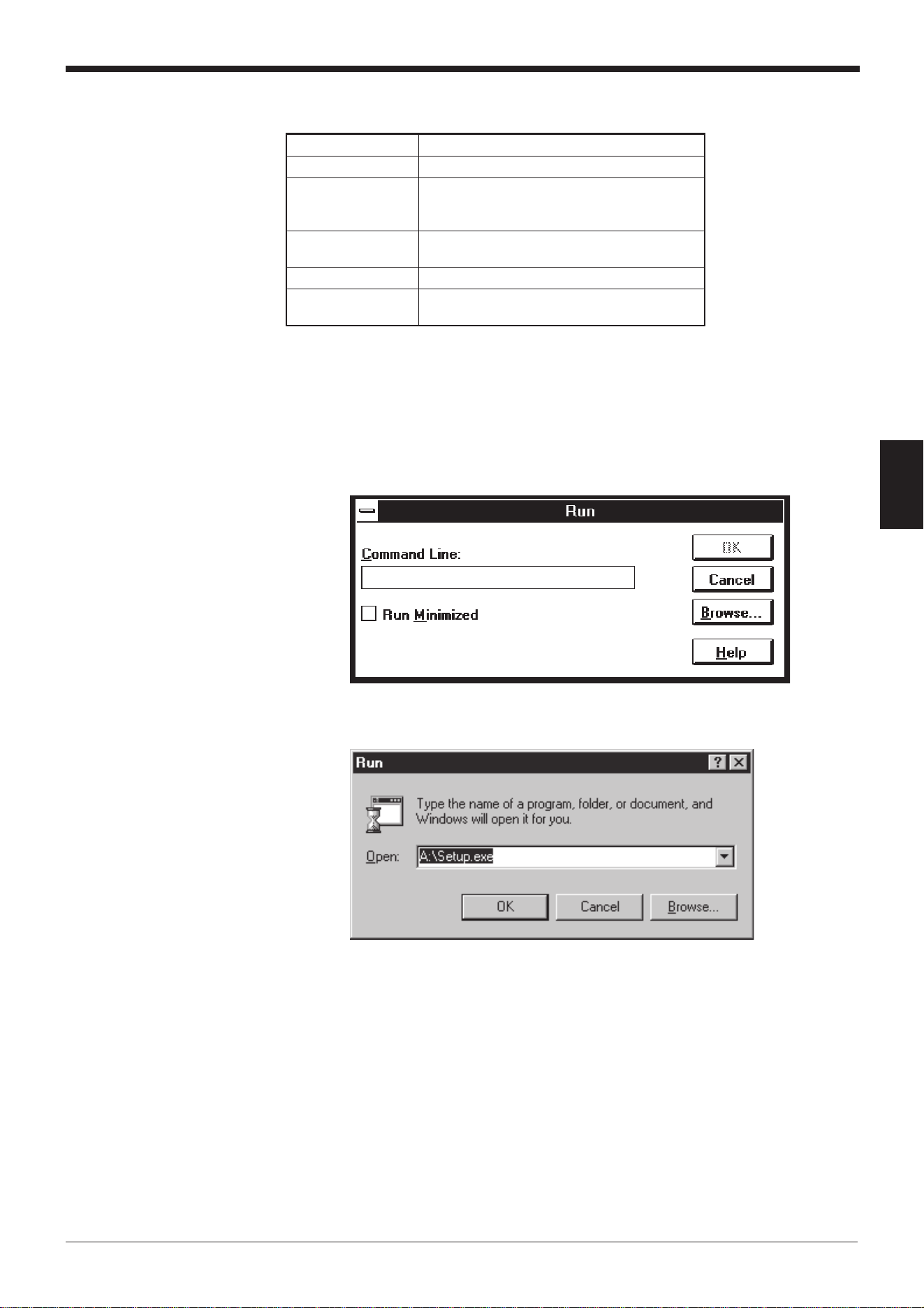
39
Chapter 4 Setup Software
4
4.1.2 Installing setup software
4.1.3 Installation/Start-up
1. Insert the BL-600 setup software system disk into the floppy drive.
2. Perform the following procedure.
• Windows 3.1:
Execute “Run...” in the icon menu of the program manager.
• Windows 95/98:
Select “Run” from the "Start" menu.
3. Run the “SETUP” file from the floppy disk drive.
Type in as follows:
A: \SETUP
4. The setup software installer starts. Follow the instructions of the installer pro-
gram.
Typically, clicking [Next (N)>] twice will complete the installation procedure.
5. Specify the directory to install the setup software into.
The setup software is normally installed in the following directory.
C: \KEYENCE\BLSET
If this directory is correct, click on [Next (N)]. If you wish to change the directory,
click on [Browse (R)..], and select the desired directory.
smetIstnemeriuqeR
CPTA/CPMBI
SO
1.3swodniW-SM
59swodniW-SM
89swodniW-SM
evirdksidyppolF
evirdksidyppolfhcni5.3
)elbitapmocBM44.1(
yalpsiDrehgihro084x046noituloseR
troplaireS
sitropC232-SRenofomuminimA
.deriuqer
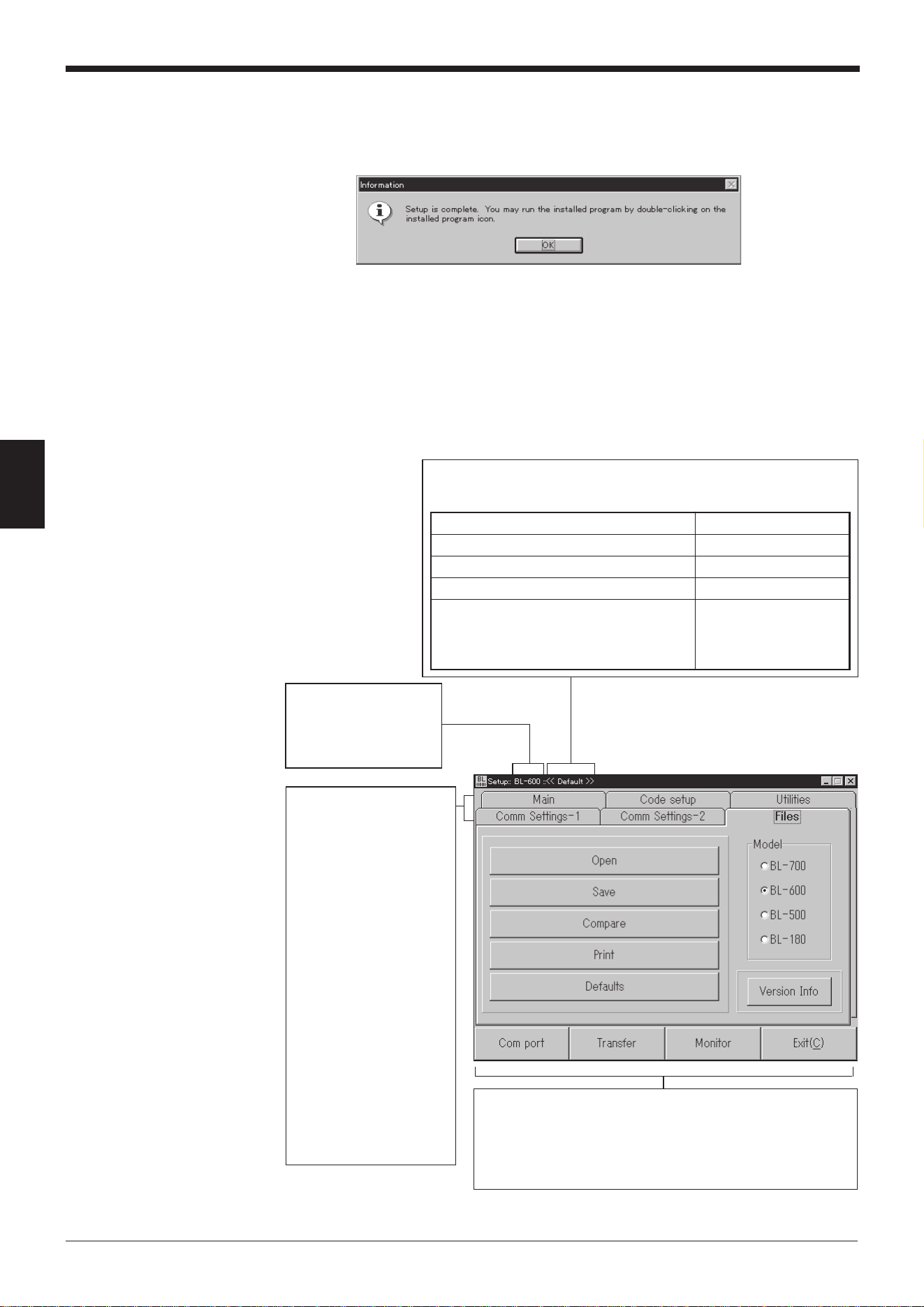
Chapter 4 Setup Software
40
4
6. Completing the installation
(1) When the installation begins, the file copy process is displayed as a graph.
(2) When the installation is complete, the following message appears.
7. Start the setup software.
For Windows Ver. 3.1, double-click the “BL” icon in the “KEYENCE” group.
For Windows 95/98, start the program from the Start Menu.
4.1.4 Initial screen
This section describes the initial screen of the setup software.
Shows the name of the stored file currently being edited, or
the status of the item currently being changed.
sutatsgnitarepOnoitacidnI
.seulavlaitiniehtevahsgnittesllA>>tluafeD<<
.yromemCPehtmorfdaersielifehT>>)emaneliF(:eliF<<
.seires006-LBehtmorfdaersielifehT>>:LB<<
morfdegnahcevahsmetieromroenO
yehtsutatsehtmorfrosgnitteslaitinieht
morfdaersawelifehtnehwtaerew
.yromem
)degnahc(
Shows the setting
options.
Main (Operation
setting:)
➮
See pages 42 to 44.
Comm Settings-1
(Communication
parameters 1:)
➮
See page 45.
Comm Settings-2
(Communication
parameters 2:)
➮
See page 46 to 48.
Code setup (Bar
code setting:)
➮
See pages 49 to 52.
Utilities:
➮
See pages 53 to 54.
Files:
➮
See pages 59 to 62.
Shows the model of
the bar code reader
that is currently
selected.
Com port:
➮
See pages 55 and 57.
Transfer:
➮
See pages 55 to 57.
Monitor:
➮
See pages 62 to 66.
Exit:
Click this button to quit the
setup software.
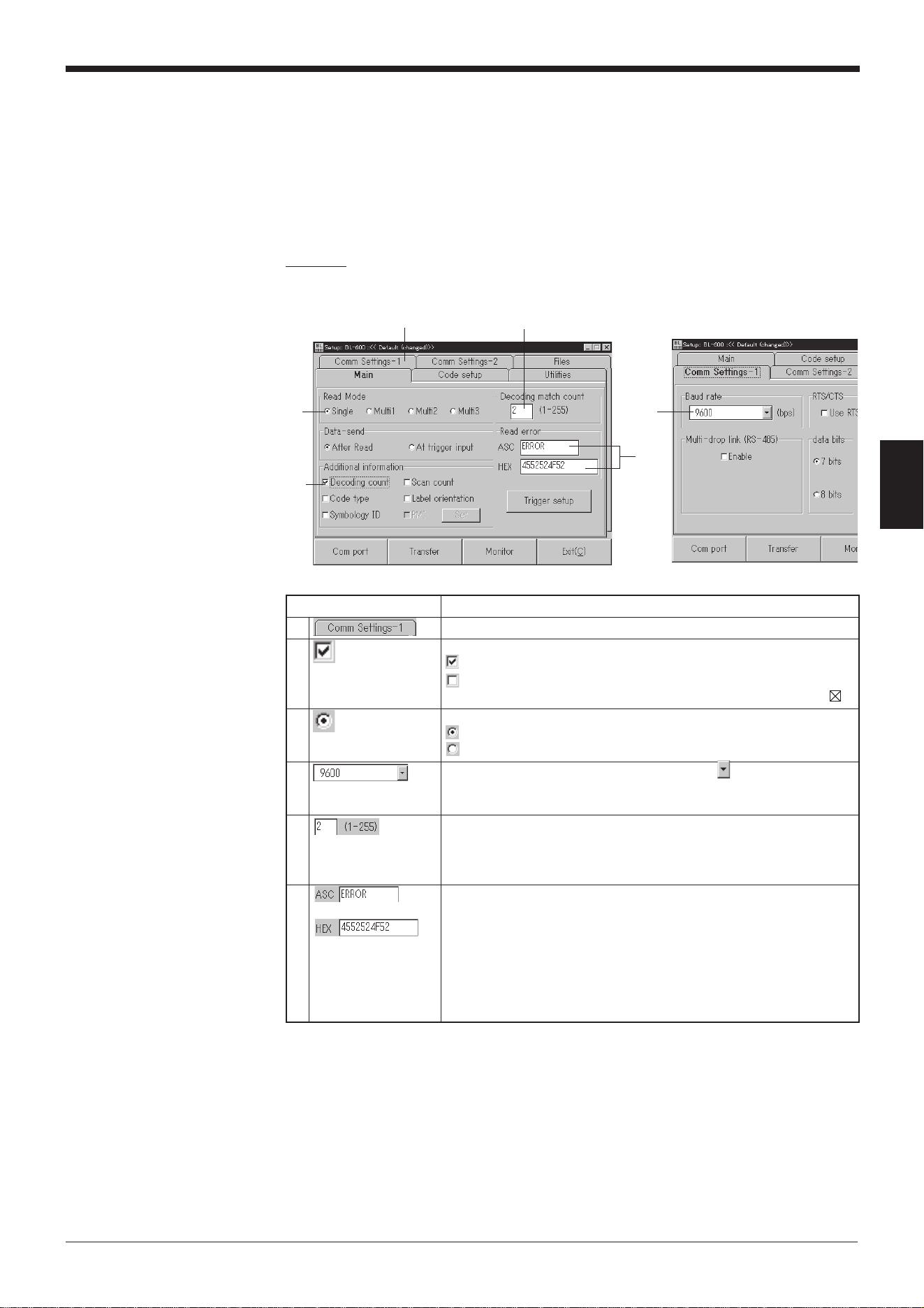
41
Chapter 4 Setup Software
4
4.1.5 Basic operation
This section describes the basic operation of the setup software.
■ Selecting items
Place the arrow (mouse pointer) on the item to be changed, and click the mouse.
■ Boxes and buttons
Example
[[Main]] [[Comm Settings-1]]
(Operation setting) (Communication
parameters 1)
6
4
5
1
3
2
noitacidnInoitarepO
1.snoitpognittesehttcelesotbatehtnokcilC
2
.smetitcelesotxobkcehcehtkcilC
.detcelessimetiehT...
.detcelestonsimetiehT...
.sadetacidnisinoitcnufdelbaneeht,1.3.reVswodniWhtiW*
3
.smetitcelesotnottuboidarehtkcilC
.detcelessimetiehT...
.detcelestonsimetiehT...
4
ehtfoedisehttakcilC.snoitpolarevesfoenotcelesotdesU
morfmetiderisedehtkcilC.unemnwod-llupehtyalpsidotxob
.unemeht
5
dnaxobehtnikcilC.xobtxetehtniseulavderisedehtretnE
.draobyekehtgnisueulavlaciremunaretne
rorrena,egnarelbaliavaehtsdeecxeeulavderetneehtfI*
.sraeppaegassem
➮ 76egapeeS.
6
retnednaxobehtnikcilC.xobtxetehtnisretcarahcretnE
.draobyekehtgnisusretcarahc
lamicedaxehfoyrtneehtstpecca”XEH“delebalxobehT
retneotxobsihtesU.draobyekehtmorf)F7ot00(srebmun
sahcus,elbatedocIICSAehtfo”h12”“ot”00“(sretcarahclortnoc
.)]XTS[dna]RC[
rorrena,egnarelbaliavaehtsdeecxeeulavderetneehtfI*
.sraeppaegassem
➮ .76egapeeS
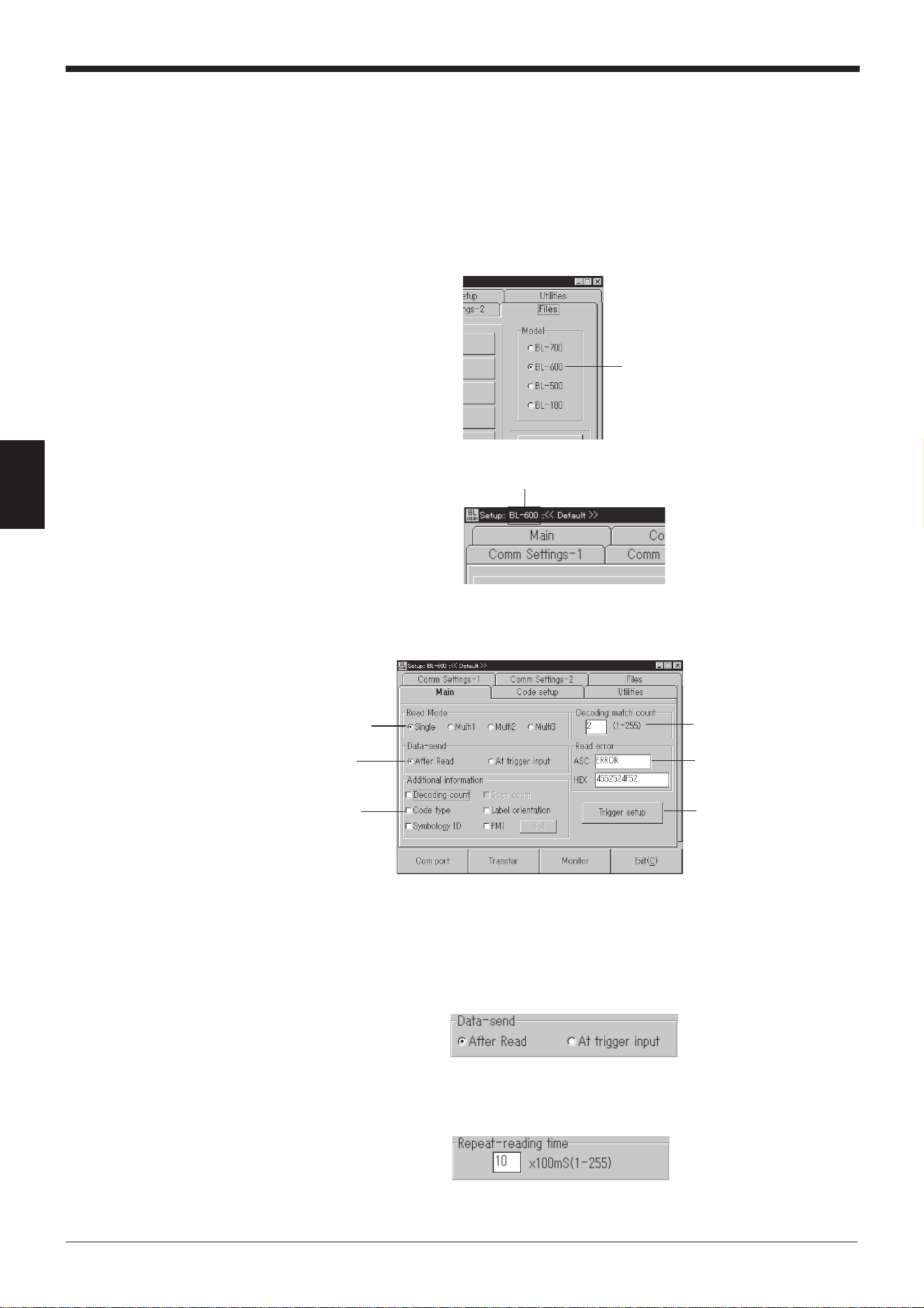
Chapter 4 Setup Software
42
4
4.2 Setup Procedure
This section describes each of the setting options.
4.2.1 Model selection
Select the model of the bar code reader on the [[Files]] screen.
1. Click “BL-600” for “Model”.
2. Check to see if “BL-600” appears as the title of the dialog box.
4.2.2 [[Main]] (Operation setting) screen
1. Set the following items.
“Read Mode” ➮
See pages 88 to 92.
Select a “Read Mode”.
Details of “Read Mode”
• If “Single” is selected:
The following box appears. Select the “Data-send” option. ➮
See page 88.
• If “Multi 1” or “Multi 2” is selected:
The following box appears. Specify a “Repeat-reading time” ➮
See page 89.
within the range of 1 to 255 (100 ms to 25.5 s).
• If “Multi 3” is selected:
Nothing appears.
Model selection
“BL-600”
“Decoding match count”
“Read Mode”
Details of
“Read Mode”
“Additional
information”
“Read error”
[Trigger setup] button
➮
See page 44.
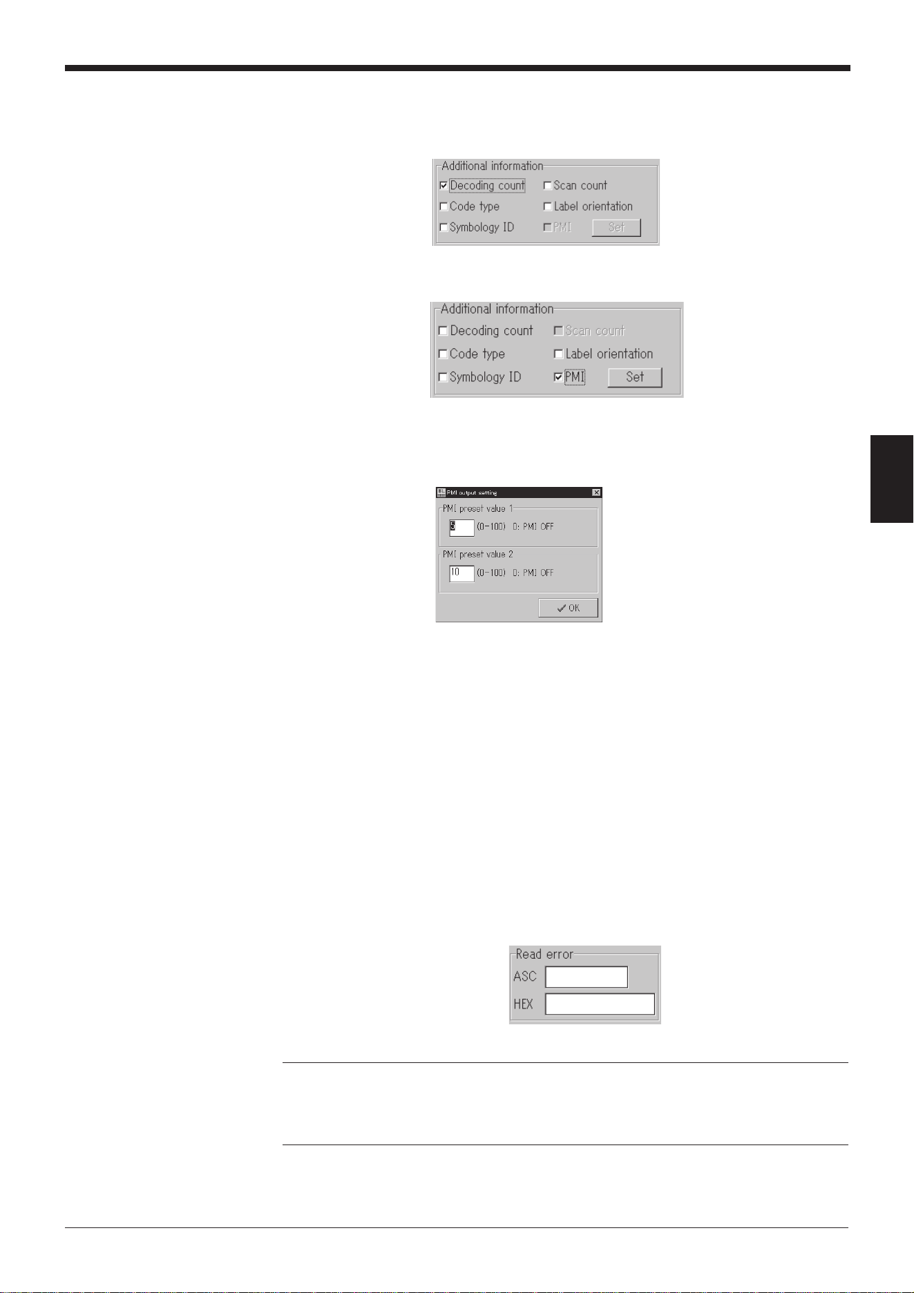
43
Chapter 4 Setup Software
4
“Additional information” ➮
See pages 102 to 106.
Select the items as required.
* “Scan count” only appears when “Decoding count” is selected.
When “PMI” is selected:
Click the [Set] button to display the “PMI output setting” screen.
Specify a value within the range of 0 to 100 for each item.
➮
See pages 104 to 106.
“Decoding match count”
Enter a desired value within the range of 1 to 255 (times).
Specifying a large number for “Decoding match count” increases the
reliability of the reading, but decreases the reading speed.
Specifying a small number for “Decoding match count” increases the
reading speed, but decreases the reliability of the reading.
Typically, the initial value “2” is used.
“Read error”
Specify the error code that the BL-600 Series will send to the personal
computer if it fails to read a bar code.
This code can be changed as desired using 8 or less characters.
Typically, the initial setting of “ERROR” is used.
If the text box is left empty, the BL-600 Series will not send a read error
code.
Reference: “Decoding match count”
The BL-600 Series judges that a bar code has been properly read when the num-
ber of scans for successful decoding (reading) of the bar code (Decoding count)
reaches the value specified in “Decoding match count”.
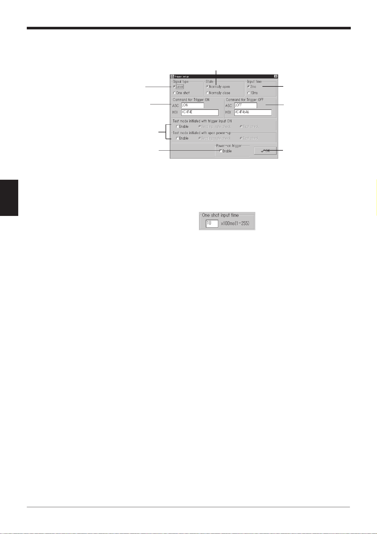
Chapter 4 Setup Software
44
4
2. Set the items for [Trigger setup].
When the [Trigger setup] button is clicked, the “Trigger setup” screen appears.
Set the following items.
“Signal type” ➮
See pages 86 and 87.
Select a “Signal type”.
• If “One shot” is selected:
The “One shot input time” setting box appears. Specify a value for the
input time within the range of 1 to 255 (100 ms to 25.5 s).
“State”
Select whether to emit a laser beam when the trigger input is on (Normally-
open) or when the trigger input is off (Normally-closed).
Starting method and type of test mode
Select this option to start the test mode if the trigger input is on or if the BL-
600 Series is turned on. Normally, this option is not selected.
* If “Test mode initiated with trigger input ON” is selected, the trigger input
cannot function normally.
“Power-on trigger”
• If “Enable” is not selected:
The BL-600 Series does not emit a laser beam for 5 seconds after it is
turned on, even if the trigger input turns on.
• If “Enable” is selected:
The BL-600 Series emits a laser beam immediately after being turned on
if the trigger input turns on.
Select this option to activate the laser beam continuously once the BL-
600 Series has been turned on.
“Command for Trigger ON”/“Command for Trigger OFF” ➮
See page 115.
Set the characters for the command used to control the reading operation
(Laser ON/OFF) with command communication.
Any number of characters, up to 8, can be set. Normally, the initial setting
(LON: Trigger ON, LOFF: Trigger OFF) should be used.
“Input time”
Specify the ON time of the trigger input to enable the signal.
Specify “10 ms” to ignore chattering of the contact when a contact type
output (relay, etc.) is used for the trigger input.
“Signal type”
“State”
Starting method and
type of test mode
Click the [OK] button to
return to the [[Main]] screen.
“Command for Trigger
OFF”
“Command for
Trigger ON”
“Input time”
“Power-on trigger”
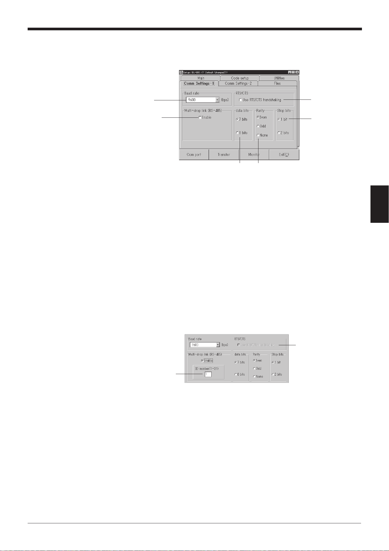
45
Chapter 4 Setup Software
4
4.2.3 [[Comm Settings-1]] (Communication parameters 1) screen
Set the following items.
“Baud rate”
“Data bits”
“Stop bits”
“Parity”
Set these communication parameters according to the settings of the exter-
nal devices that will be connected (PC, PLC, etc.).
“Multi-drop link (RS-485)”
➮
See “Multi-drop controller N-400 User’s Manual”.
1. Select “Enable” to use multi-drop link.
* If the multi-drop link is enabled, “RTS/CTS” is disabled.
2. The “ID number (1-31)” setup box appears. Specify the ID number as a
value between 1 to 31. Be sure not to set the same number for different
BL-600 units in the same multi-drop link.
“RTS/CTS” ➮
See page 112.
Select “RTS/CTS” to suspend read data transmission with the CTS signal of
RS-232C.
“Baud rate”
“Stop bits”
“RTS/CTS”
“Parity”
“Data bits”
“Multi-drop link
(RS-485)”
“RTS/CTS”
Cannot be selected.
“ID number (1-31)”
Chapter 4 Setup Software
46
4
4.2.4 [[Comm Settings-2]] (Communication parameters 2) screen
PLC link setting
The settings vary depending on whether or not the PLC link will be used. First,
select whether or not to use the PLC link with “Use PLC”.
If the PLC link is not used
1. Set the following items.
“Handshaking” ➮
See pages 111 and 112.
Select the type of communication forms (communication protocol) to send
the read bar code data from the BL-600 Series to the personal computer.
“Checksum” ➮
See pages 167 and 168.
You can add data to check for incorrect data translation, such as garbled
characters in the serial communication.
“Header”
“Delimiter” ➮
See page 113.
Select the transmission format to send the read bar code data.
If “Custom” is selected, the following text boxes appear. Type the desired
header and delimiter (up to 5 characters) in each box.
“Use PLC”
• If the PLC link is not used:
➮
See page 46.
• If the PLC link is used:
➮
See page 48.
“Checksum”
[Character] button
➮
See page 47.
[Option] button
➮
See page 47.
“Handshaking”
“Header”
“Delimiter”
47
Chapter 4 Setup Software
4
2. Set the items for [Character].
When the [Character] button is clicked, the following screen appears.
Set each item.
“Partition mark (1 character)”
Specify the partition mark to separate the bar code data read with the BL-
600 Series and additional information. ➮
See pages 102 to 106.
Any one character can be used. Normally, the initial setting of (:) should be
used.
“Intermediate delimiter (5 chars max.)”
Specify the intermediate delimiter to separate each bar code data read in
“Multi-label read mode 2 “ (➮
See page 90.)
or “Multi-label read mode 3”.
➮
See page 91.
Any characters, up to 5, can be used. Normally, the initial setting of (,)
should be used.
3. Set the item for [Option].
When the [Option] button is clicked, the following screen appears.
Specify the “Send delay time”.
“Send delay time”
Specify the response time, within the range of 0 to 255 (ms), for the time
between the instant the BL-600 Series receives a command from the PC
and the instant the BL-600 Series sends back a response.
“Partition mark”
(1 character)
Click the [Return]
button to return to the
[[Comm Settings-2]]
screen.
“Intermediate
delimiter”
(5 chars max.)
“Send delay time”
Click the [Return] button
to return to the [[Comm
Settings-2]] screen.
Chapter 4 Setup Software
48
4
If the PLC link is used
Set the following items.
➮
Refer to “Chapter 8, PLC Link” for details.
“Connected PLC”
Specify the model of the PLC to be connected.
“PLC trigger area” ➮
See page 137.
Check “Enable” to send a trigger signal to the BL-600 Series using the PLC
link.
“Station No.”
Specify a station number between 0 to 31.
“DM head address” ➮
See page 135.
Specify a value for the head address of DM within the range of 0000 to 9900.
“File Register enable”
1. Select “File Register enable” to use the file register (➮
See page 131.
) as a
device.
2. If the file register is enabled, the following screen appears. Specify a
value, within the range of 000 to 255, for the block number of the file
register to be used.
“Station No.”
* “Station No.” is
not displayed if
“KEYENCE KV
Series” is selected
for “PLC setup”.
“File Register enable”
* “File Register enable” is
only displayed if
“MELSEC-A Series” is
selected for “PLC setup”.
“DM head address”
[Character] button
➮
See step 2 on page 47
.
“Connected PLC”
“PLC trigger area”

49
Chapter 4 Setup Software
4
4.2.5 [[Code setup]] (Bar code setting) screen
1. Set the type of bar codes, readout digits and other functions.
Type of bar code
Select the type of bar code to be used.
* If four different types of bar codes are specified in “Code 1” to “Code 4”,
the BL-600 Series can read 4 types of bar codes without changing
settings.
“Code length”
Specify the maximum number of digits for the bar code in “Max=” and the
minimum number of digits in “Min=”.
• For “CODE39”
Specify a value, between 3 and 32, for the number of digits including the
“*” (start/stop character) and a check digit.
• For “ITF”
Specify a value, between 2 and 32, for the number of digits including a
check digit (even numbers only).
• For “(Industrial) 2of5” and “COOP 2of5”
Specify a value, between 1 and 32, for the number of digits including a
check digit.
• For “Codabar”
Specify a value, between 3 and 32, for the number of digits including “a”,
“b”, “c”, “d” (start/stop characters) and a check digit.
• For “UPC/EAN”
A setting for the number of digits is not required. Select whether or not to
enable the reading of each of 13-digit EAN (UPC-A), 8-digit EAN, and
UPC-E.
• For “CODE93”
Specify a value, between 1 and 32, for the number of digits without a
start/stop code and a check digit.
• For “CODE128”
Specify the number of digits without a start/stop code, check digit, FUN1
to 4 (function codes), “SHIFT”, and “CODE-A/B/C”.
The available range varies depending on the type of start code (CODE-A
to C).
• CODE-A/B: 1 to 31 digits
• CODE-C: 1 to 64 digits
Type of bar code
[Options] button
➮
See page 52.
[Details] button
➮
See page 50.
“Code length”
Chapter 4 Setup Software
50
4
Note 1: For “ITF”, “(Industrial) 2of5”, and “COOP 2of5”, be sure to fix the number of
digits according to the bar code actually used. Otherwise, some digits may be
skipped (not read) without recognition.
Example
To fix the number of digits to “8”
Specify “Max=” as “8” and “Min=” as “8”.
Note 2: It is recommended to fix the number of digits for “Codabar”. Some digits
may be skipped depending on the print condition or the position of the bar code
reader.
Note 3: When reading only one type of bar code, specify it in “Code 1” and leave
the other boxes as “None”. This decreases the possibility of misreading.
2. Set the items for [Detail].
When the [Detail] button of “Code 1” through “Code 4” is clicked, the “Bar code
detail setup” screen appears.
Specify each item.
The items vary depending on the specified type of bar code.
For “CODE39”
•“Send start/stop character (*)”
If “Send start/stop character (*)” is set, the BL-600 Series adds an “*”
(asterisk) to the read data and sends it to the PC.
•“Inspect check-digit [Modulus 43]”
If “Inspect check-digit [Modulus 43]” is set, the option “Send check-digit”
is activated (displayed in black).
•“Send check-digit”
If “Send check-digit” is set, the BL-600 Series sends the read data with
the check digit to the PC.
For “ITF”
•“Inspect check-digit [Modulus10/Weight3]”
If “Inspect check-digit [Modulus10/Weight3]” is set, the option “Send
check-digit” is activated (displayed in black).
•“Send check-digit”
If “Send check-digit” is set, the BL-600 Series sends the read data with
the check digit to the PC.
Click the [OK] button to return
to the [[Code setup]] screen.
“Send check-digit”
“Inspect check-digit
[Modulus 43]”
“Send start/stop character (*)”
Click the [OK] button to return
to the [[Code setup]] screen.
“Send check-digit”
“Inspect check-digit
[Modulus10/Weight3]”
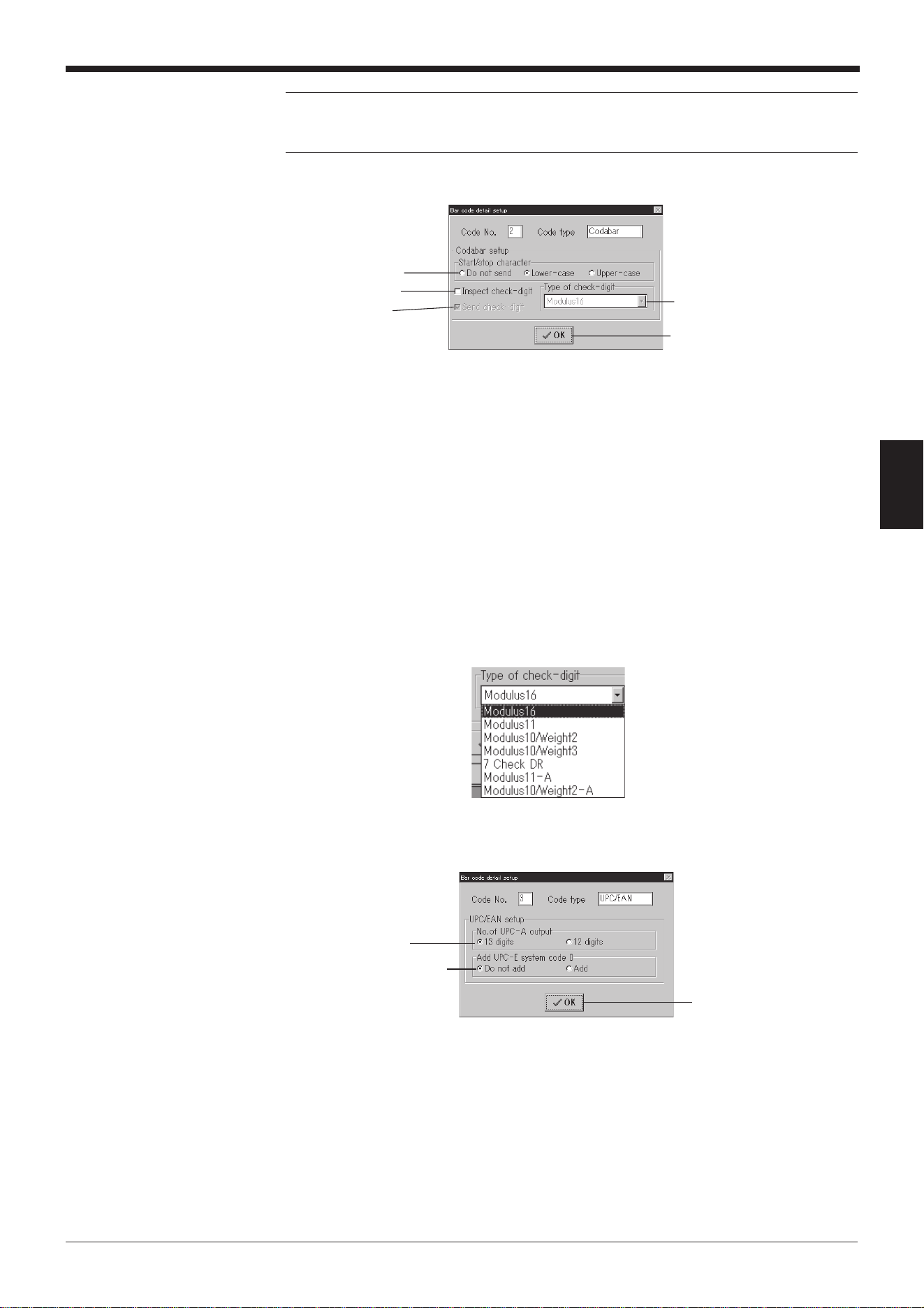
51
Chapter 4 Setup Software
4
Note: When reading a standard distribution code (bar codes on carton boxes), fix
“Code length” to 14 or 16 digits in the [[Code setup]] screen and enable “Inspect
check-digit [Modulus10/Weight3]”.
For “Codabar”
•“Start/stop character”
If “Lower-case” or “Upper-case” is set, the BL-600 Series adds an “a”, “b”,
“c”, or “d” (lowercase or uppercase) to the read data and sends it to the
PC.
•“Inspect check-digit”
If “Inspect check-digit” is set, the option “Send check-digit” is activated
(displayed in black).
•“Send check-digit”
If “Send check-digit” is set, the BL-600 Series sends the read data with
the check digit to the PC.
•“Type of check-digit”
Select the type of check digit to use.
For “UPC/EAN”
•“No. of the UPC-A output”
Specify whether to use a 13-digit or a 12-digit output when reading the
UPC-A data.
•“Add UPC-E system code 0”
If “Add” is selected, the BL-600 Series adds a “0” to the beginning of the
data and sends it to the PC.
* The check digit setting is not provided on the screen, but the BL-600 Series
internally calculates it using modulus 10/weight 3. (The data is sent.)
“Send check-digit”
Click the [OK] button to return to
the [[Code setup]] screen.
“Type of check-digit”
“Start/stop character”
“Inspect check-digit”
“No. of UPC-A output”
“Add UPC-E system code 0”
“Add UPC-E system code 0”
is only displayed when
reading the UPC-E data.
Click the [OK] button to return
to the [[Code setup]] screen.
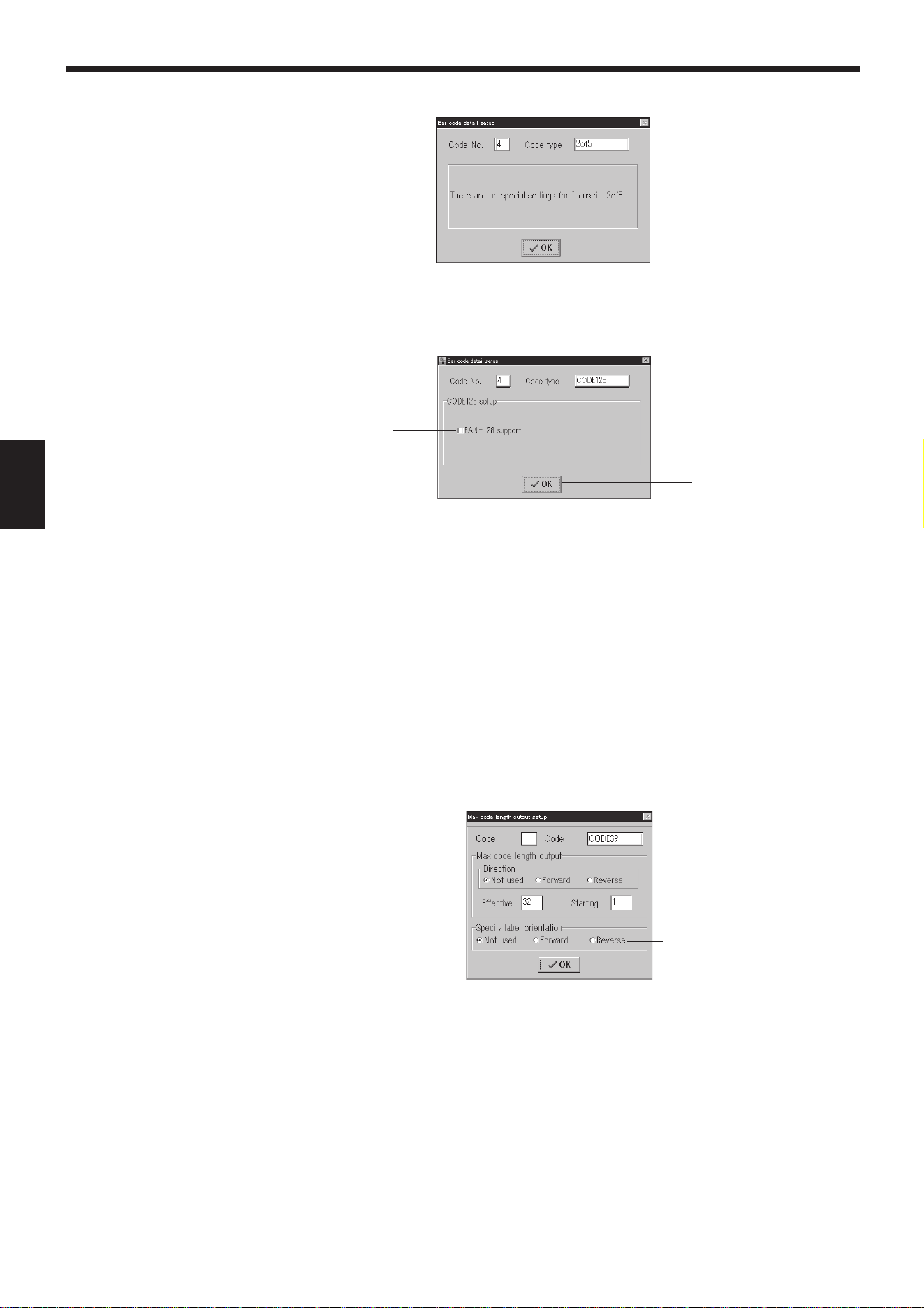
Chapter 4 Setup Software
52
4
For “(Industrial) 2of5”, “COOP 2of5”, and “CODE93”
There are no detail setting parameters for these bar codes.
For “CODE128”
“EAN-128 support”
Check “EAN-128 support” to enable the BL-600 Series to accept the data
configuration of EAN-128 specified as the international standard distribution
code. ➮
See page 166.
* The check digit setting is not provided on the screen, but the BL-600
Series internally calculates it using modulus 103. (The data is not sent.)
3. Set the items for [Options].
When the [Options] button is clicked for “Code 1” to “Code 4”, the “Max code
length output setup” screen appears.
Set each item.
“Max code length output” ➮
See page 107.
To output only the selected digit(s) from the read data, specify the direction
in which to select (“Direction”), the digit at which to begin selection (“Start-
ing”), and the number of digits to be selected (“Effective”).
“Specify label orientation” ➮
See page 93.
If “Specify label orientation” is set, the BL-600 Series only reads bar codes
moving with the specified orientation. Bar codes moving with any other
orientation are not read.
Click the [OK] button to return
to the [[Code setup]] screen.
Click the [OK] button to return
to the [[Code setup]] screen.
“EAN-128 support”
“Max code length output”
Click the [OK] button to return to
the [[Code setup]] screen.
“Specify label orientation”
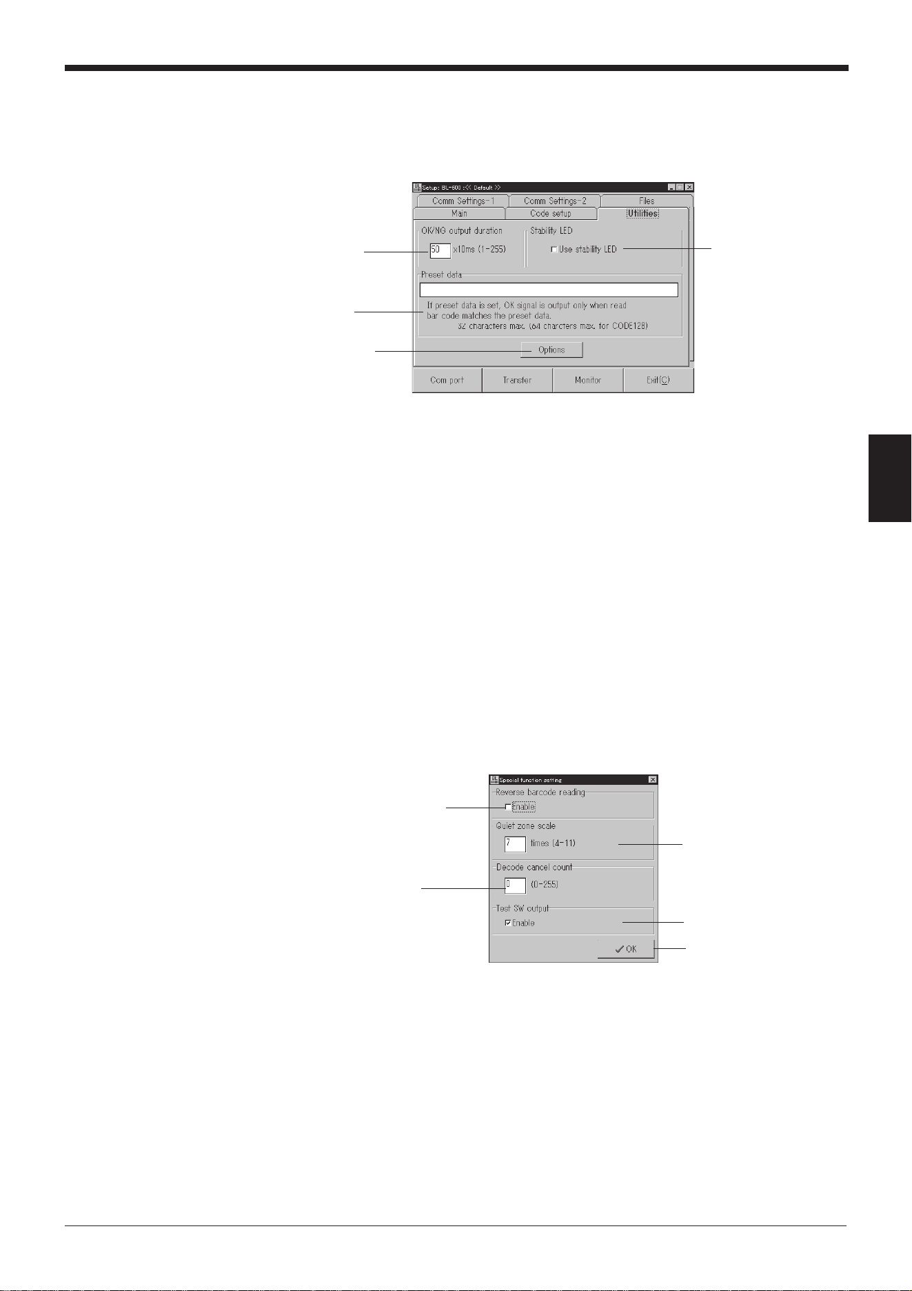
53
Chapter 4 Setup Software
4
4.2.6 [[Utility]] screen
1. Set the following items.
“OK/NG output duration”
Set the “OK/NG output duration” with a numerical value between 1 and
255 (10 ms to 2.55 s).
“Preset data” ➮
See page 101.
Set the length, up to 32 characters, of the bar code data to be entered.
* If CODE-C is set for CODE128, up to 64 characters can be set.
“Stability LED” ➮
See page 99.
If “Use stability LED” is set, the BL-600 Series displays the STABILITY
LEDs, which indicate the reading reliability during normal reading operation.
2. Set the items for [Options].
When the [Options] button is clicked, the “Special function setting” screen
appears.
Set each item.
“Reverse bar code reading”
If “Enable” is checked, the BL-600 Series reads bar codes printed in reverse
(white-on-black).
“Decode cancel count”
Do not change from the initial value.
“Quiet zone scale”
Set the minimum value of the quiet zone width to be read with the BL-600
Series. Specify the scale factor of the quiet zone with reference to the
narrow bar width (the narrowest bar width in the bar code). Do not change
the initial value unless the quiet zone of the target bar code is small.
“Stability LED”
[Options] button
➮
See below.
“Preset data”
“OK/NG output
duration”
Click the [OK] button to
return to the [[Utility]] screen.
“Reverse bar code reading”
“Decode cancel count”
“Quiet zone scale”
“Test SW output”
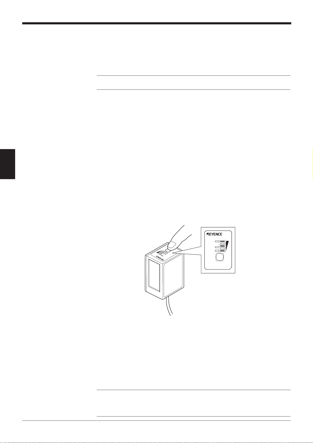
Chapter 4 Setup Software
54
4
4.3 Sending/Receiving Settings
This section describes how to send data to or receive data from the BL-600 Series.
4.3.1 Sending/receiving settings to/from the BL-600 Series
Perform the following procedure to read the settings of the BL-600 Series or to
send the updated settings to the BL-600 Series.
* To send/receive settings to/from the BL-600 Series via the BL-V35, refer to the
BL-V35 User’s Manual.
1. Connect the BL-600 Series, special power supply unit, and personal computer.
➮
See “Chapter 3, Connection and Wiring”.
2. Set the BL-600 Series to “setting data send/receive waiting status”.
1) Press the BL-600 TEST switch for 8 seconds.
2) When the 1st, 3rd and 5th STABILITY LEDs from the top flash simulta-
neously, the communication protocol is temporarily set as indicated below.
• Baud rate: 9600 bits/s
• Data length: 7 bits
• Parity: Even
• Stop bit length: 1 bit
• PLC link: Disabled
• Multi-drop link: Disabled
Reference: If you know the current communication parameter settings of the BL-
600, this step is not necessary. You can send data to the BL-600 by setting the
communication parameters of the host computer using [[Com Port]] so that they
conform to the current settings of the BL-600.
LASER ON
OK/NG
T
IM
IN
G
TEST
LASER ON
OK/NG
TIMING
TEST
BL-600
“Test SW output”
If “Enable” is set, the BL-600 Series sends the read bar code data or the
successful reading rate data to the PC while in test mode.
If you do not want to send data while in test mode, remove the check from
“Enable”. ➮
See pages 96 and 98.
* This setting is effective for all reading operations using the TEST switch.
Reference: “Quiet zone” is the margin required on the right and left of a bar code.
Normally, it should be 10 or more times wider than the narrow bar width.
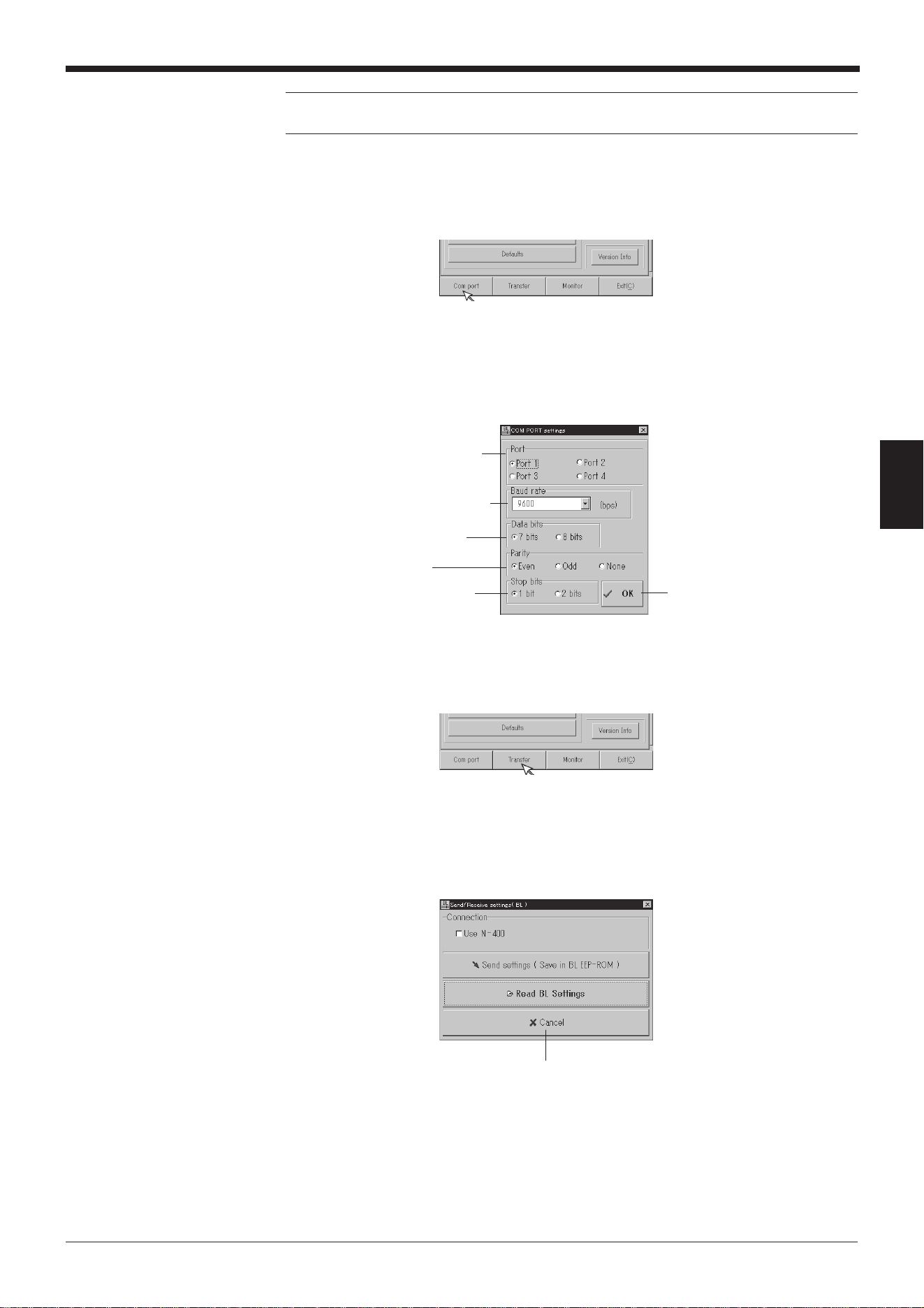
55
Chapter 4 Setup Software
4
Note: If PLC link is enabled, you cannot send data to the BL-600 without perform-
ing this step because the handshaking protocol is set for PLC link only.
3. Check or change the communication parameter settings of the personal com-
puter.
1) Click on [[Com port]].
2) Set each parameter as shown below.
3) Select an appropriate RS-232C port.
4) When the settings are complete, click the [OK] button.
4. Sending/receive settings to/from the BL-600 Series via the N-400.
1) Click on [[Transfer]].
2) The “Send/Receive settings (BL)” screen appears.
• To send the updated settings to the BL-600 Series
Click the [Send settings] button.
• To read the settings of the BL-600 Series
Click the [Read BL settings] button.
Baud rate: 9600 bits/s
Stop bit length: 1 bit
Parity: Even
Data length: 7 bits
Select an appropriate
RS-232C port.
Click the [Cancel] button to return
to the previous screen.
Click the [OK] button to return
to the previous screen.
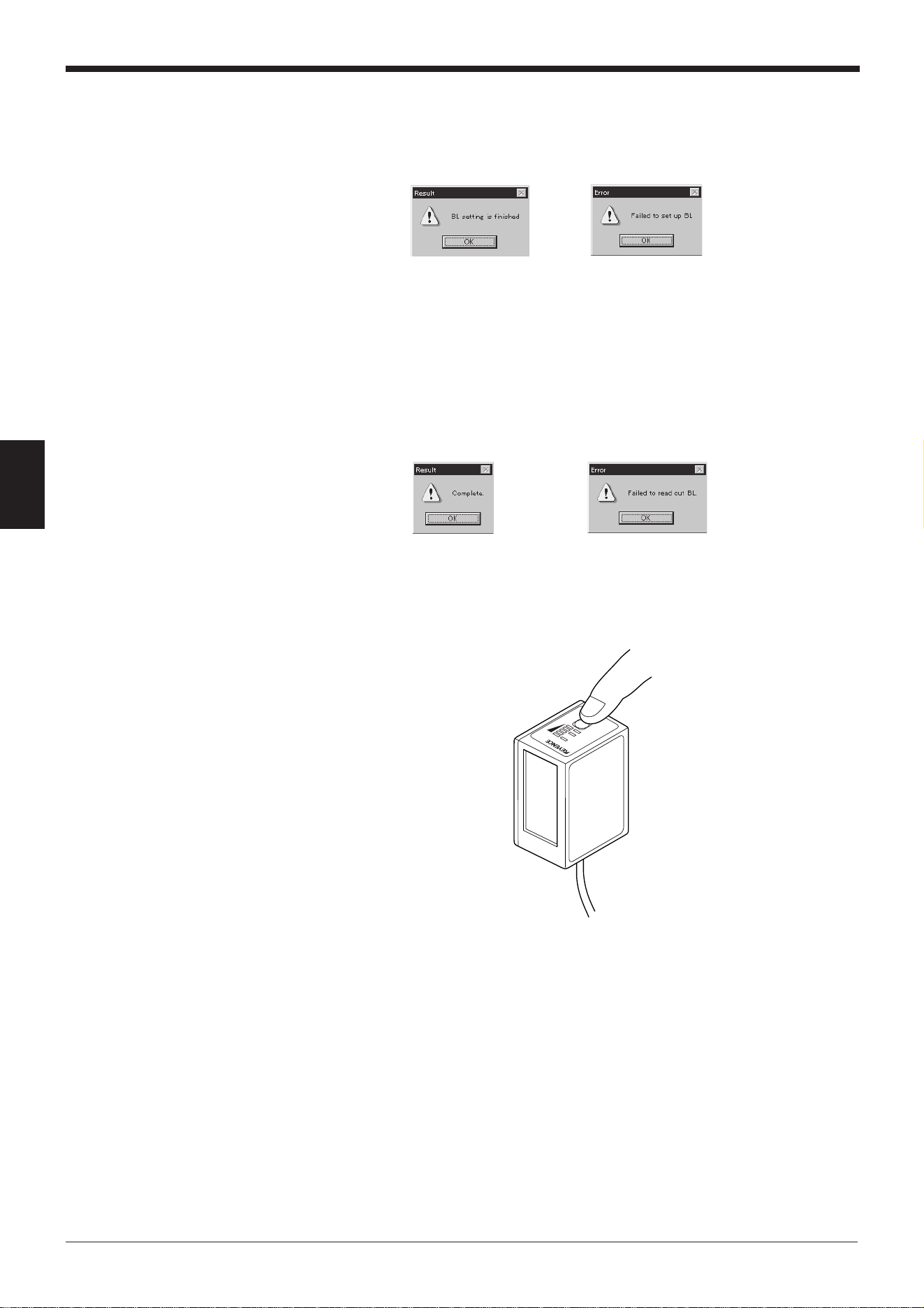
Chapter 4 Setup Software
56
4
5. Sending/reading result
The following messages appear to indicate whether the sending/receiving
operation was successful or whether it failed.
If the operation failed, check the following points:
• Check that the BL-600 Series is in the “setting data send/receive waiting
status” during which the 1st, 3rd, and 5th STABILITY LEDs from the top
flash simultaneously.
• Check that [[Com port]] is set as shown in (3).
• Check that the special power supply is turned on.
• Check that the RS-232C cable pin assignment of the BL-600 is the same as
that of the host computer. ➮
See pages 21, 28 and 35.
6. Canceling the “setting data send/receive waiting status”.
Press the TEST switch once. The “setting data send/receive waiting status” is
canceled.
Sending succeeded Sending failed
Reading succeeded Reading failed
LAS
ER
O
N
OK/NG
TIM
ING
TEST
Press the TEST switch once.
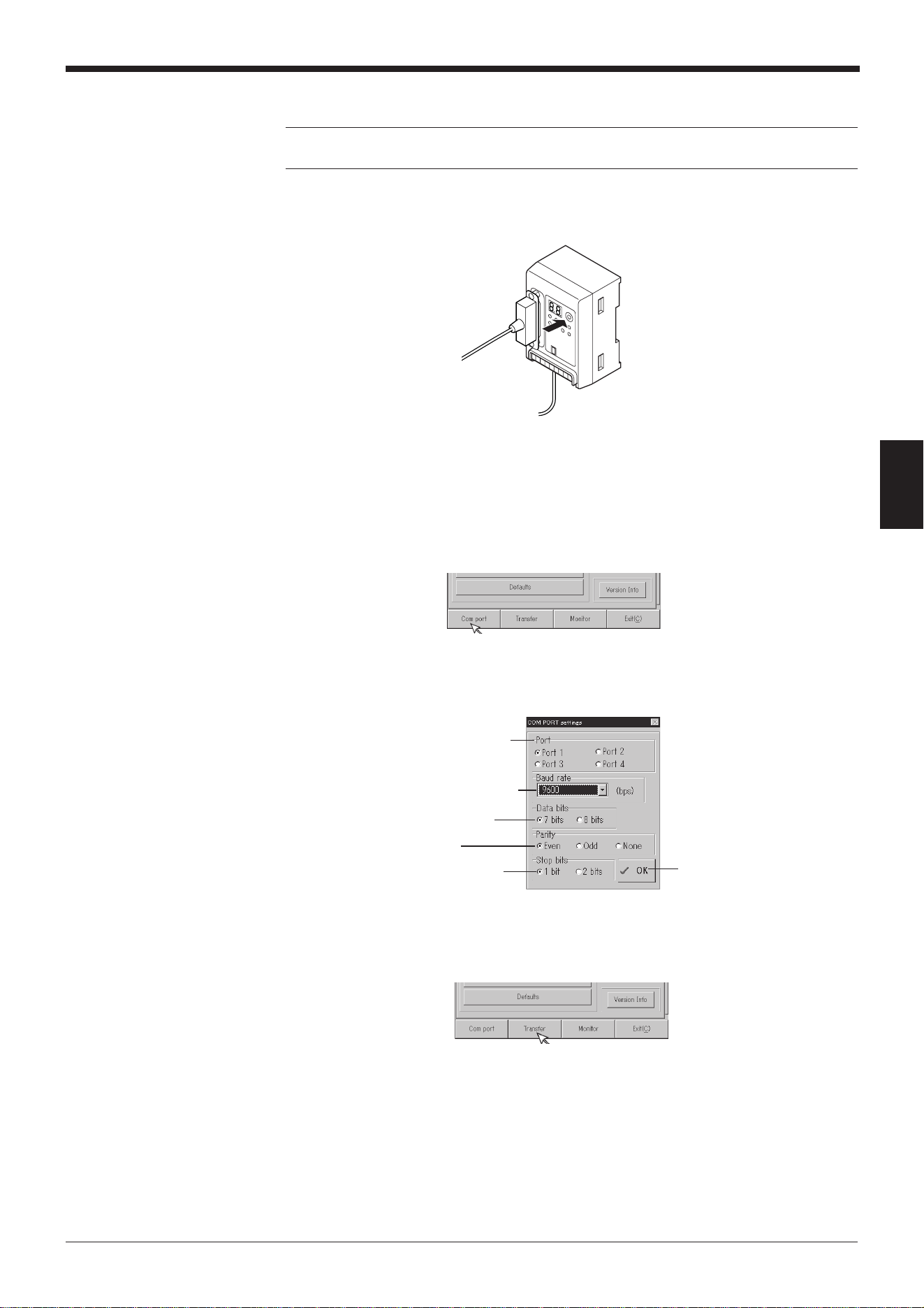
57
Chapter 4 Setup Software
4
4.3.2 Sending/receiving settings to/from the BL-600 Series via the N-400
Note: It is only possible to send/receive settings with a BL-600 Series that has
already established a multi-drop link with the N-400.
1. Set the N-400 to “setting data send/receive waiting status”.
1) Press the N-400 TEST switch for 5 seconds.
2) Communication can begin when “SO (50)” is displayed.
2. Check or change the communication parameter settings of the personal com-
puter.
1) Click on [[Com port]].
2) Set each parameter as shown below.
3) Select an appropriate RS-232C port.
4) When the settings are complete, click the [OK] button.
3. Sending/receive settings to/from the BL-600 Series via the N-400.
1) Click on [[Transfer]].
Baud rate: 9600 bits/s
Stop bit length: 1 bit
Parity: Even
Data length: 7 bits
Select an appropriate
RS-232C port.
Click the [OK] button to return
to the previous screen.
Press the TEST switch
for 5 seconds.
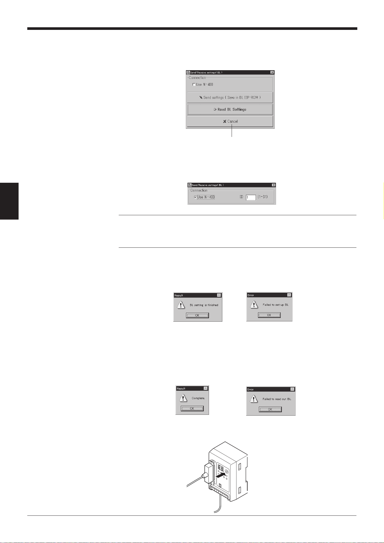
Chapter 4 Setup Software
58
4
2) The “Send/Receive settings (BL)” screen appears.
• To send the updated settings to the BL-600 Series
Select “Use N-400” and enter the ID number of the desired BL-600
Series. Then, click the [Send settings] button.
• To read the settings of the BL-600 Series
Select “Use N-400” and enter the ID number of the desired BL-600
Series. Then, click the [Read BL settings] button.
Note: If improper settings are sent to the BL-600 Series, communication with the
N-400 is disabled.
To avoid problems, read the settings of the BL-600 Series first, then change only
the necessary items.
4. Sending/reading result
The following messages appear to indicate whether the sending/receiving
operation was successful or whether it failed.
If the operation failed, check the following points:
• Check that the N-400 displays “SO (50)”.
•
Check that the settings for the [[Com port]] are specified as described in step 2.
• Check that the N-400 and special power supply unit are turned on.
• Check that the multi-drop link between the N-400 and the BL-600 Series is
properly established.
5. Canceling the “communication waiting status”.
Press the TEST switch of the N-400 once. The “communication waiting status”
is canceled.
Click the [Cancel] button to return
to the previous screen.
Sending succeeded Sending failed
Reading succeeded Reading failed
Press the TEST switch once.
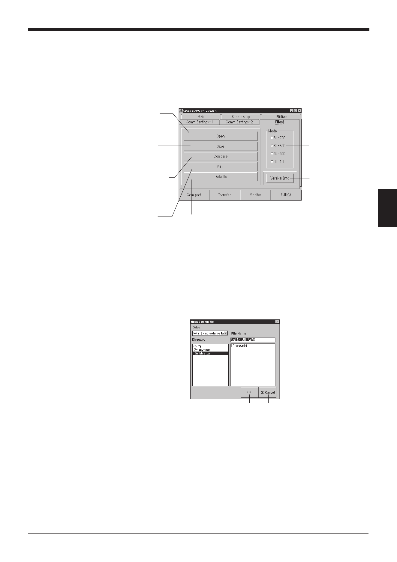
59
Chapter 4 Setup Software
4
4.4 Reading/Saving/Printing File
This section describes how to read, save, or print settings of a file.
4.4.1 [[Files]] screen
The [[Files]] screen allows the following operation/setting of files (setting data).
4.4.2 Reading a previously saved setting file
1. Click the [Open] button.
The “Open Settings file” screen appears.
2. Select a file and click the [OK] button.
The saved file is opened.
[Open] button
Reads a file contain-
ing the saved settings
of the BL-600 Series.
[Save] button
Saves the updated
settings of the BL-600
Series to a file.
[Compare] button
Compares the file
currently being edited
with a file that was
previously saved.
[Print] button
Prints the setting.
[Version Info] button
Displays the version of
the software.
“Model”
Select the model of the
bar code reader that will
be used.
[Defaults] button
Resets the edited settings to
the initial (factory) settings.
[OK] button
Click [Cancel] to return to
the previous screen.
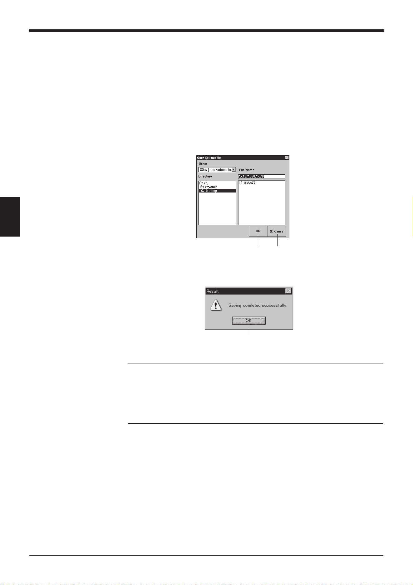
Chapter 4 Setup Software
60
4
4.4.3 Saving updated settings in a file
1. Click the [Save] button. The “Save Settings file” screen appears.
2. Click in the file name entry field and enter a file name.
Up to 8 characters can be used for a file name.
3. Click the [OK] button.
• If the entered file name is illegal, an error message appears and the file is
not saved.
In this case, click the [OK] button and repeat steps 1 to 3.
➮
See page 67.
• If the file is properly saved, the following message appears.
Reference: If a file saved with a name consisting of only alphanumerics (alphabets
and numbers) is sent to the BL-600 Series, the file name is also sent. In this case,
when you read the settings of the BL-600 Series the next time, you can also read
the file name to check the name of the current file of the BL-600 Series. This is
convenient for maintenance.
If characters other than alphanumerics are included in a file name, the file name is
not sent to the BL-600 Series because the BL-600 Series cannot recognize them.
[OK] button
Click [Cancel] to return to the
previous screen.
Click the [OK] button to return to the
initial screen.
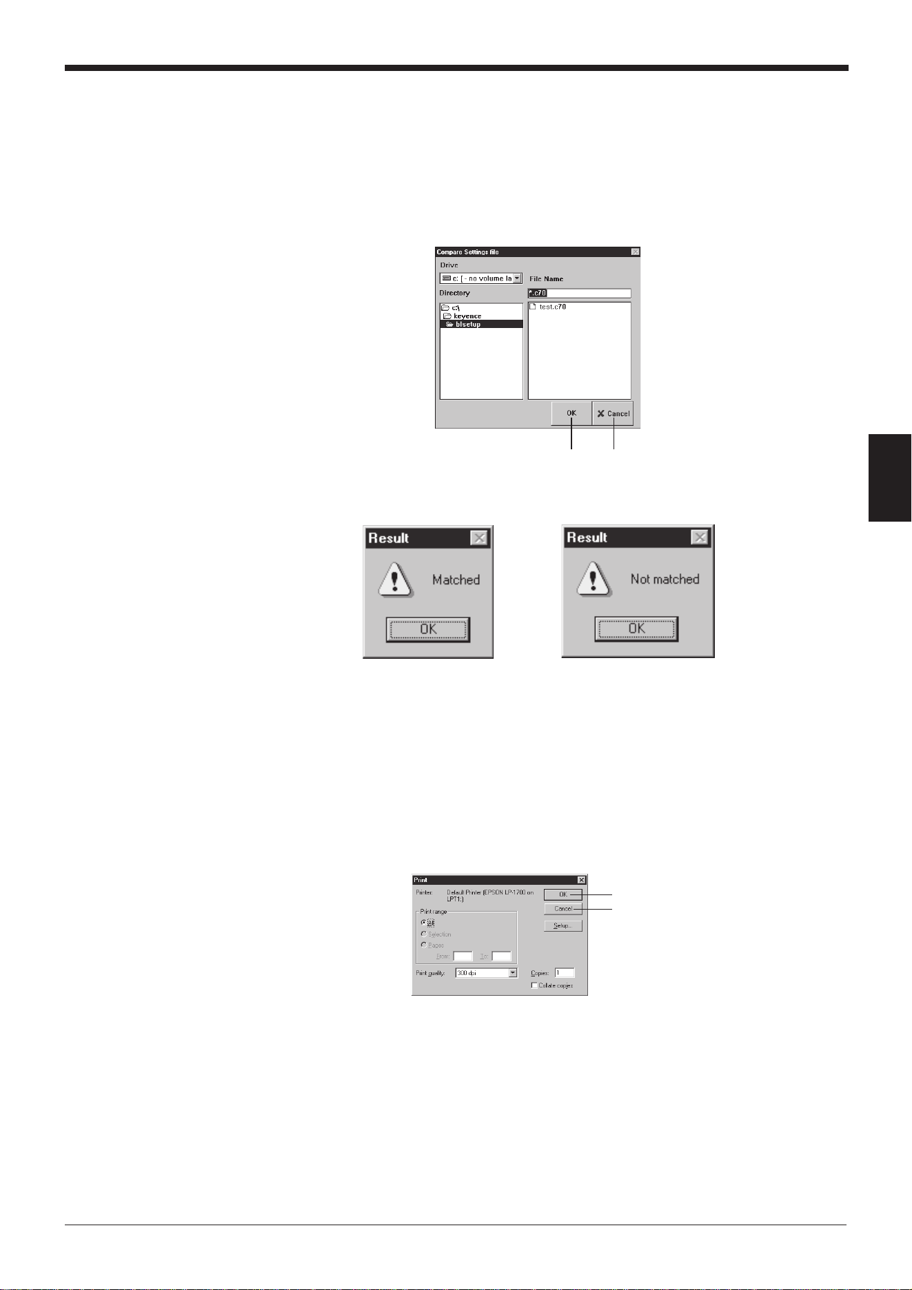
61
Chapter 4 Setup Software
4
4.4.4 Comparing the contents of the file currently being edited with a saved
file
1. Click the [Compare] button. The “Compare Settings file” screen appears.
2. Select a saved file to be compared and click the [OK] button.
The selected saved file is compared with the file currently being edited.
4.4.5 Printing contents of a setting file
1. Click the [Print] button. The “Print” screen appears.
2. Specify each item as required.
3. Click the [OK] button to start printing.
Click [Cancel] to return to the
previous screen.
If the settings match
If the settings do not match
Click [Cancel] to return to the
previous screen.
[OK] button
[OK] button
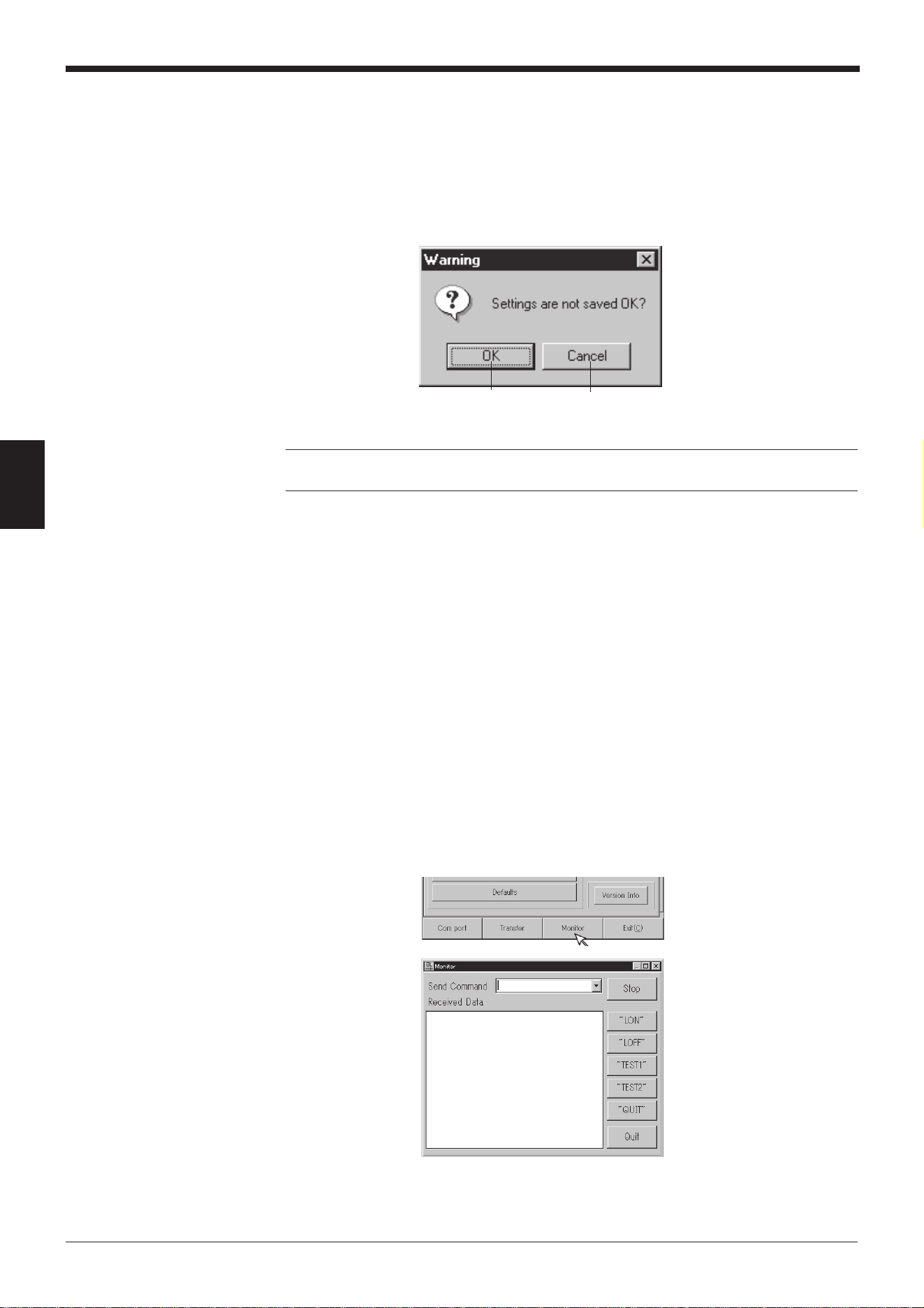
Chapter 4 Setup Software
62
4
4.4.6 Resetting the edited settings to the initial (factory) settings
1. Click the [Defaults] button.
If you click this button without saving the file currently being edited, a warning
message appears.
2. To continue the initialization, click the [OK] button.
Note: The [Defaults] button operation is used to initialize the edited settings of the
setup software. The settings on the BL-600 Series cannot be initialized.
4.5 Using Monitor
This setup software provides the “Monitor” program to check if the BL-600 can
send data properly. The “Monitor” program allows you to display the data read by
the BL Series on the host computer’s monitor screen, and also to send a command
from the host computer to the BL-600 or BL Series.
4.5.1 Receiving data and checking the result
The bar code data read with the BL-600 Series can be received with a personal
computer and checked on the screen.
1. Set the communication parameters of the personal computer according to those
of the BL-600 Series.
➮
See pages 54 and 55.
2. Click on [[Monitor]]. The MONITOR screen will appear.
[OK] button
Click [Cancel] to return to the
previous screen.
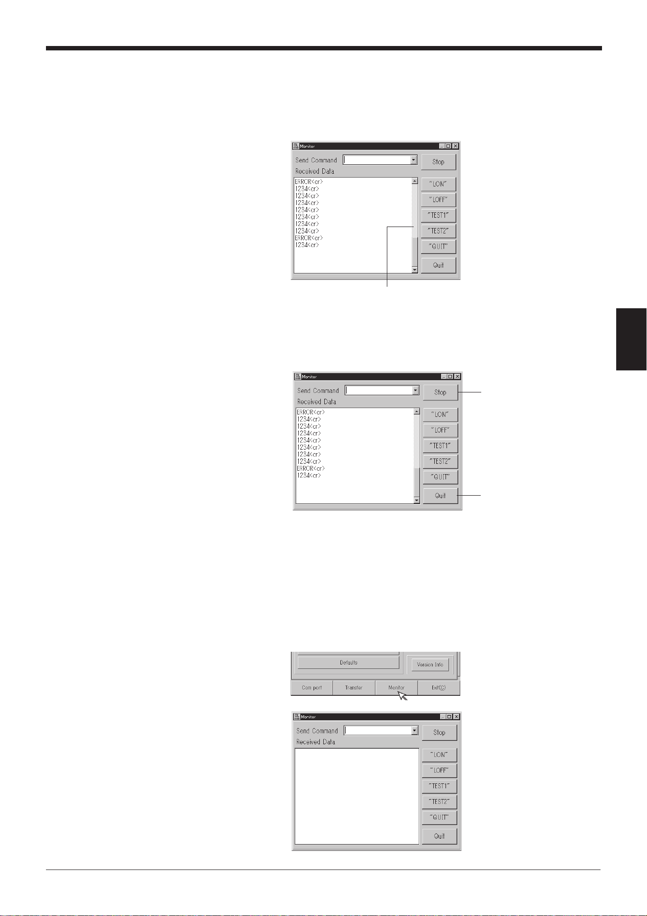
63
Chapter 4 Setup Software
4
3. Receive the bar code data.
• The bar code data read with the BL-600 Series is displayed on the “Re-
ceived Data” field.
• You can also see the history of the previous data (up to 1000 lines) using the
scroll bar on the right of the “Received Data” field.
4. Stopping the bar code data display
1) Click the [Stop] button. The name of the button changes to [Start] and
display of the received data is stopped.
2) When the [Start] button is clicked, the name of the button changes to [Stop]
and display of the received data is restarted.
4.5.2 Command transmission ➮
See pages 114 to 128.
1. Set the communication parameters of the personal computer according to those
of the BL-600 Series. ➮
See pages 54 and 55.
2. Click on [[Monitor]]. The MONITOR screen will appear.
Scroll bar
[Stop] button
Click [Quit] to return to the
previous screen.
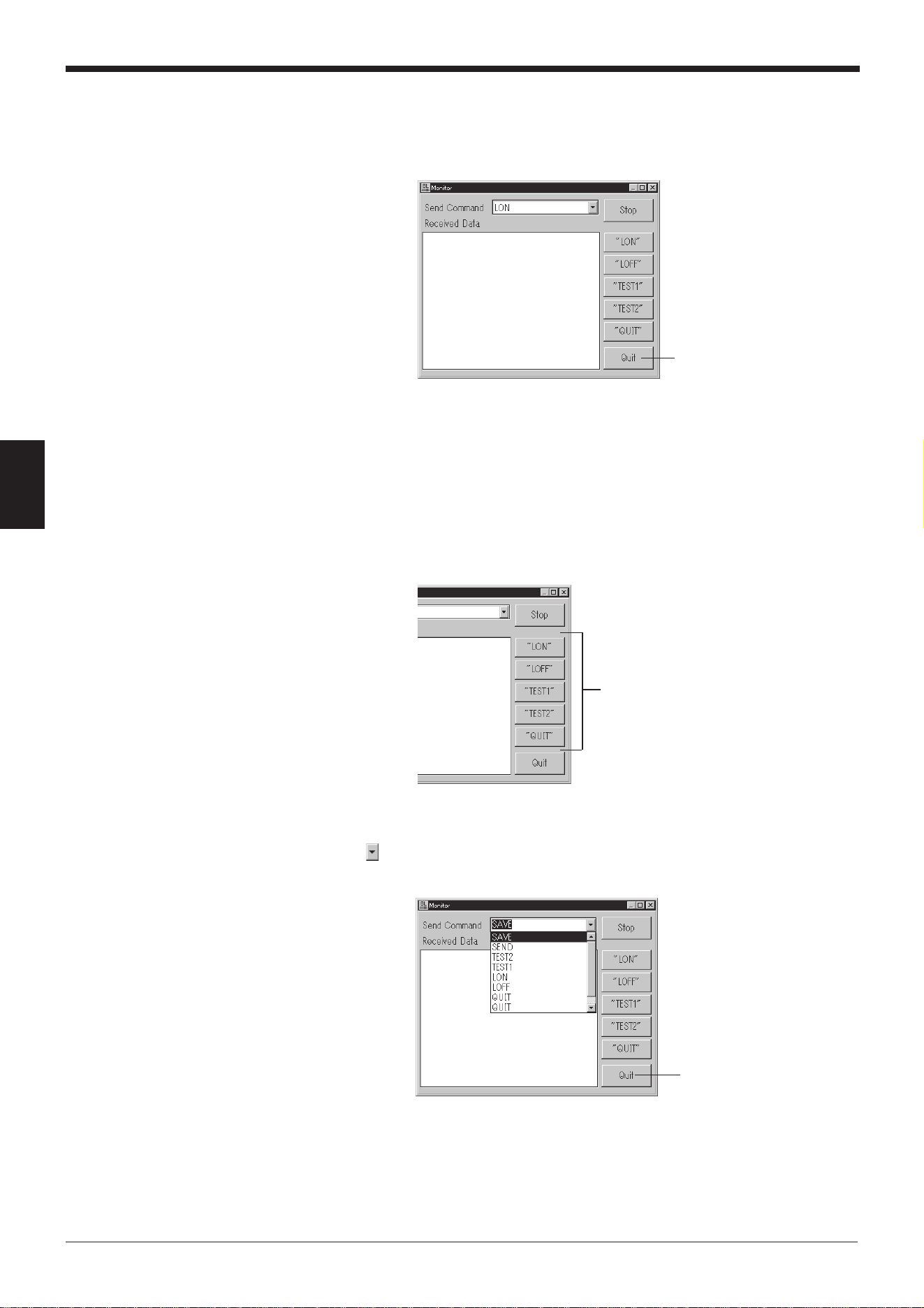
Chapter 4 Setup Software
64
4
Command buttons
Click [Quit] to return to
the previous screen.
3. Enter the serial communication command in the “Send Command” field (➮
See
pages 114 to 128.
) and press the [ENTER] key on the keyboard. Now, commands
can be sent from a personal computer to the BL-600 Series.
* Use only uppercase characters for the commands.
• Command transmission with the command buttons
Clicking the command buttons on the right side of the screen allows the
following commands to be sent to the BL-600 Series.
[TEST1] button: Activates the reading rate check mode.
[TEST2] button: Activates the tact check mode.
[QUIT] button: Quits the test mode.
[LON] button: Starts reading.
[LOFF] button: Quits reading.
4. Checking the history of sent commands
Clicking of the “Send Command” field displays the history of the sent com-
mands (up to 100 commands).
[Quit] button
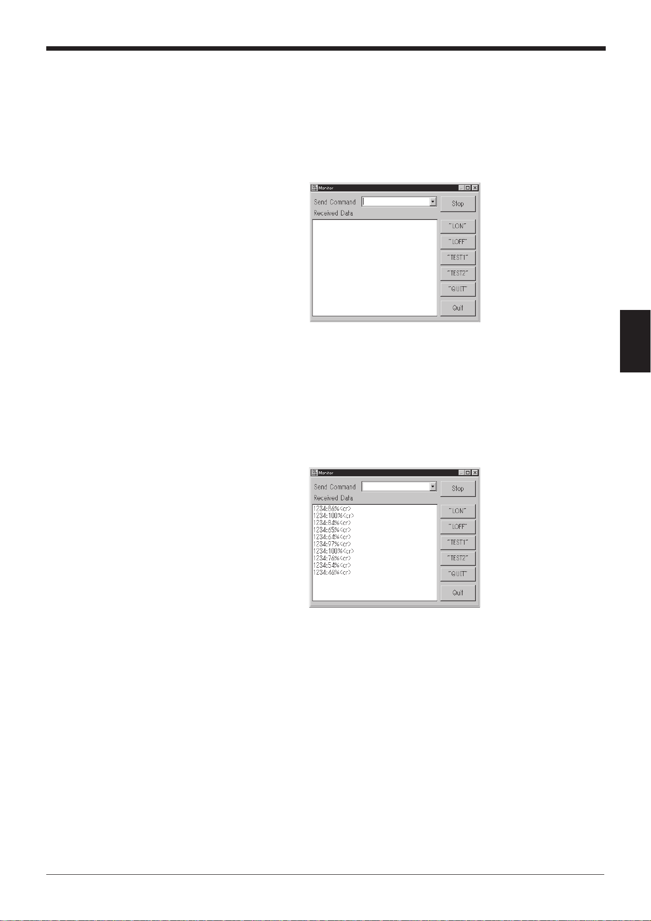
65
Chapter 4 Setup Software
4
4.5.3 Starting the test mode
The test mode of the BL-600 Series can be started with a command button.
1. Set the communication parameters of the personal computer according to those
of the BL-600 Series. ➮
See pages 54 and 55.
2. Click on [[Monitor]]. The MONITOR screen will appear.
3. Start the test mode by clicking the [TEST1] or [TEST2] button.
Operation of the BL-600 Series
[TEST1] button: Activates the reading rate check mode.
[TEST2] button: Activates the tact check mode.
* You can also start the test mode by typing “TEST1” or “TEST2” (uppercase
only) in the “Send Command” field and sending it.
4. When the [QUIT] button is clicked, test mode is finished.
* You can also end the test mode by typing “QUIT” in the “Send Command”
field and sending it.
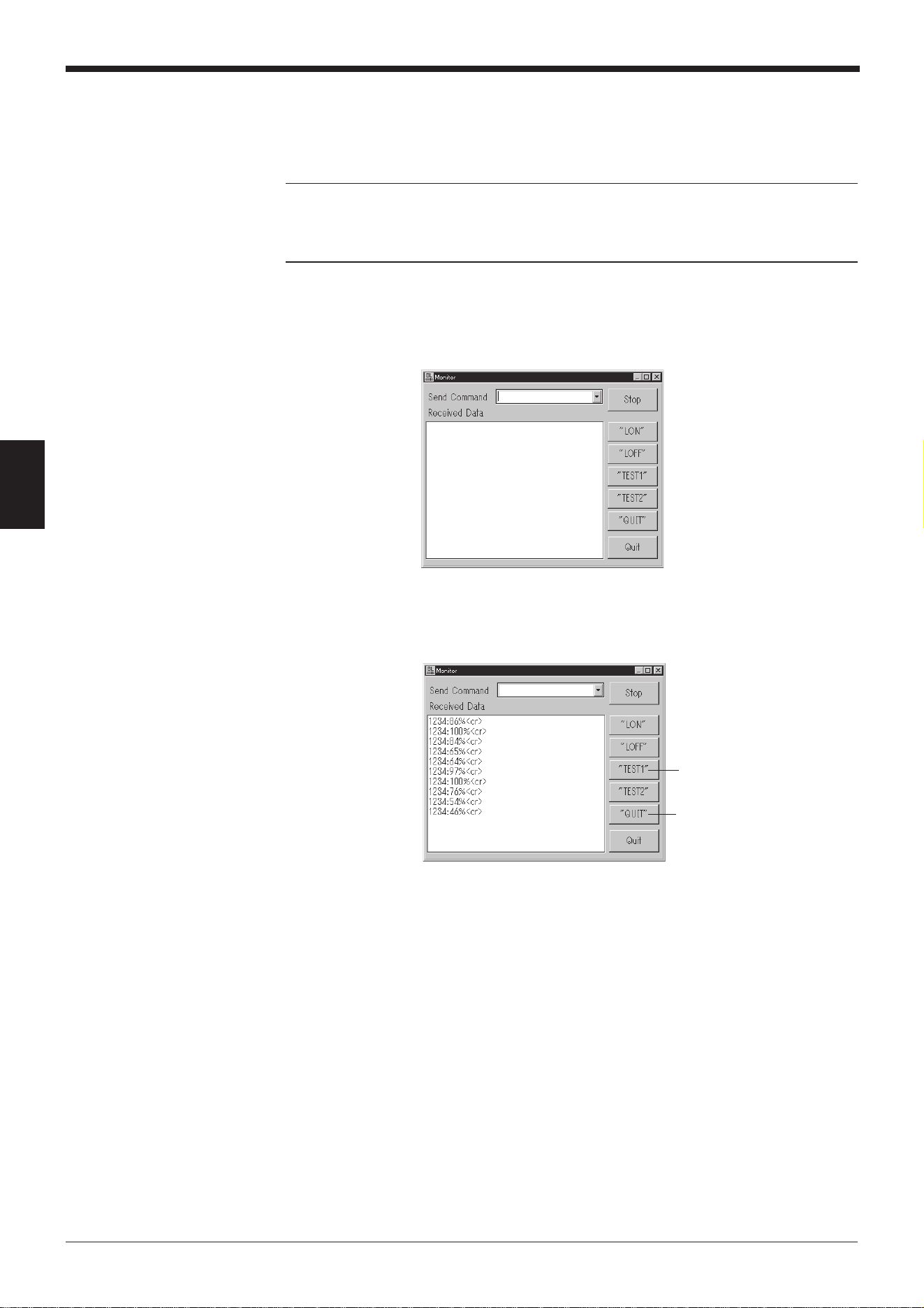
Chapter 4 Setup Software
66
4
4.5.4 Changing the scanning width
The scanning width of the BL-600 Series can be changed with a command button.
➮
See page 117.
Note: When the scanning width is changed, the laser beam may not be properly
applied to the bar codes, resulting in poor readings. Change the scanning width
only when it is necessary. Thoroughly check that the change did not affect the
reading performance.
1. Set the communication parameters of the personal computer according to those
of the BL-600 Series. ➮
See pages 54 and 55
.
2. Click on [[Monitor]]. The MONITOR screen will appear.
3. Click the [TEST1] button.
The BL-600 Series enters test mode and emits a laser beam.
4. Specify the starting angle of scanning.
Send the following command.
SDEG a [ENTER] [a: 0 to 400 (Unit: 0.1°)]
↑ [*Initial value = 0]
Input from the keyboard
* Specify an appropriate angle by checking the field of the laser beam.
5. Specify the scanning angle.
Send the following command.
WDEG b [ENTER] [b: 400 to 600 (Unit: 0.1°)]
↑ [*Initial value = 600]
Input from the keyboard
* Specify an appropriate angle by checking the field of the laser beam.
Clicking the [QUIT] button
quits the test mode.
[TEST1] button
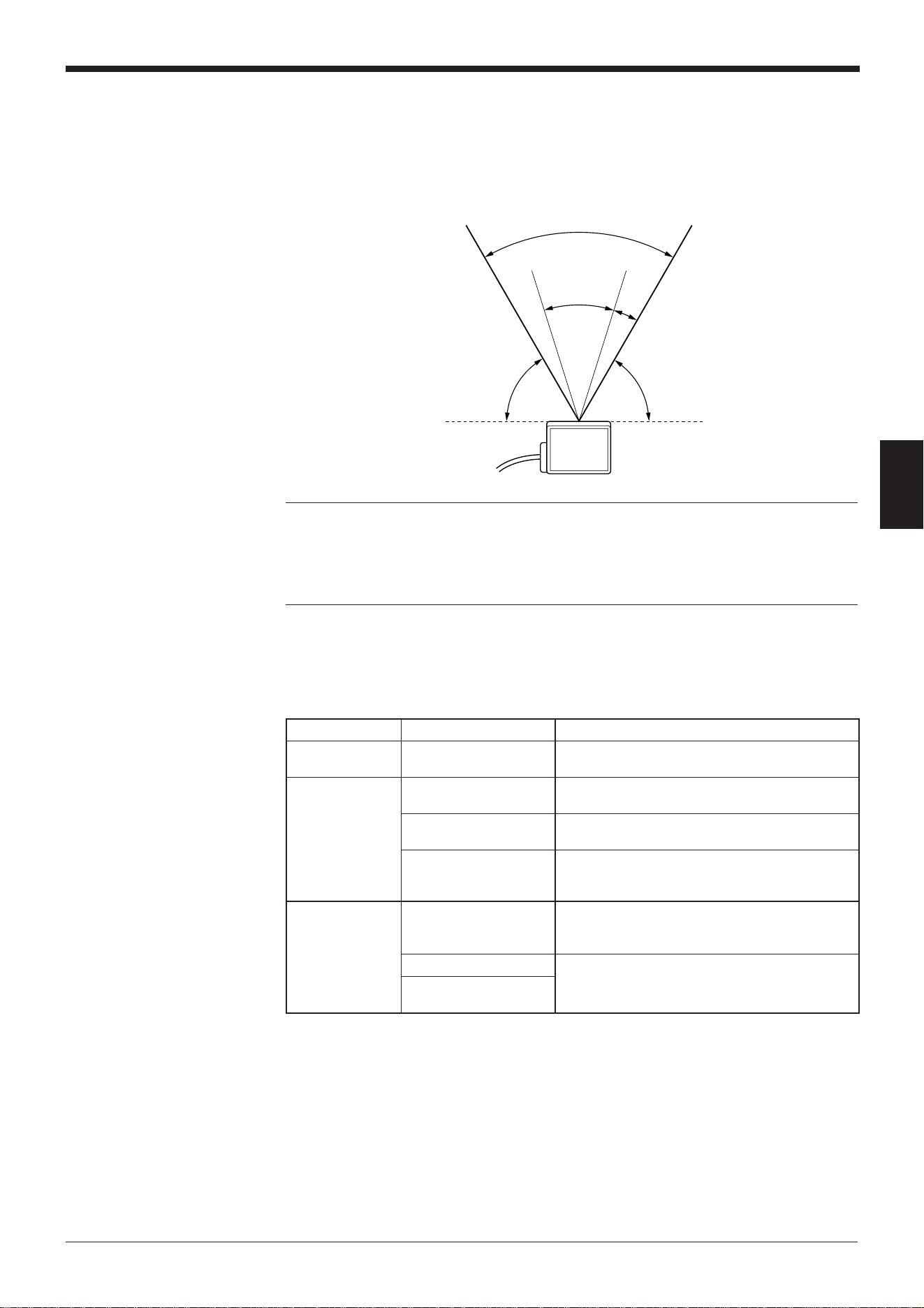
67
Chapter 4 Setup Software
4
6. When the setting is complete, quit the test mode.
Click the [QUIT] button.
* The changed scanning width is retained even after the BL-600 Series is
turned off.
Note 1: The scanning width cannot be specified to exceed the angle range be-
tween “c” and “d” (60°).
Note 2: The angle specified in the steps above should be used as a guide. If a
precise setting is required, adjust the position of each bar code reader separately
after installation.
d
b
60°
a
c
Approx. 60°
Approx. 60°
egassemrorrEstnetnoC
gnirudsrorrE
putes
siatadderetnE“
”]KO[.tcerrocni
.tcerrocnisiatadderetneehT
.atadtcerrocehtretne-eR
gnirudsrorrE
noitacinummoc
htiwnoitacinummoC“
”]KO[.deliaf006-LB
006-LBehthtiwnoitacinummocgnirudrorrE
.)sgnittesgnidnesrof(
➮ .65egapeeS
006-LBmorftuodaeR“
”]KO[.deliaf
006-LBehthtiwnoitacinummocgnirudrorrE
.)sgnittesgnidaerrof(
➮ .65egapeeS
siledomdeificepsehT“
”]KO[.tcerrocni
ehttonsierawtfosputesehtnitesledomehT
.detcennocsitahtledomehtsaemas
➮ .24egapeeS
elifsrorrE
gnitide
gnirudelifgnisseccA“
”]KO[.detcejer
.detresnisiksidyppolfoN
.detcetorp-etirwsiksidyppolfehT
.llufsiksidyppolfehT
”]KO[.dnuoftoneliF“
eliftcerrocaretnE.tcerrocnisiemanelifehT
.eman
➮ .06egapeeS
.tcerrocniemaneliF“
”]KO[
4.6 List of Error Messages

Chapter 4 Setup Software
68
4
/ / / New setting data [Untitled] / / /
< < Model = BL-600 > > [x] Selected
[_] -----------
=> Changed
1) Main
[Read mode] [x] Single [_] Multi 1 [_] Multi 2 [_] Multi 3
[Data-send] [x] After read [_] At trigger input
[Repeat-reading time] [10] x 100 ms
[Decoding match count] [2] times
[Read error] ERROR [4552524F52]
[Add Decoding match count] [_] Enable
[Add scan count] [_] Enable
[Add code type] [_] Enable
[Add label orientation] [_] Enable
[Add symbology ID.] [_] Enable
[Add PMI.] [_] Enable
2) Trigger setup
[Signal type] [x] Level [_] One shot
[One shot input time] [10] x 100 ms
[Input time] [x] 2 ms [_] 10 ms
[State] [x] Normally open [_] Normally close
[Command for Trigger ON] LON [4C4F4E]
[Command for Trigger OFF] LOFF [4C4F4646]
[Test mode initiated with input ON] [x] OFF [_] Reading-rate check [_] Tact check
[Test mode initiated upon power-up] [x] OFF [_] Reading-rate check [_] Tact check
[Power-on trigger] [_] Enable
3) Comm Settings–1
[Baud rate] 9600 bps.
[data bits] [x] 7 bits [_] 8 bits
[Parity] [x] Even [_] Odd [_] None
[Stop bits] [x] 1 bit [_] 2 bits
[RTS/CTS] [_] Use RTS/CTS handshaking
[Multi-drop link(RS-485)] [_] Enable
[ID number] No. [1]
4) Comm Settings–2
[Use PLC] [_] Enable
[Handshaking] [x] None [_] PASS/RTRY [_] ACK/NAK
[Header] [x] None [_] STX [_] ESC [_] Custom
[Delimiter] [x] CR [_] CR+LF [_] ETX [_] Custom
[Partition mark] : [3A]
[Intermediate delimiter] , [2C]
[Checksum] [_] Enable
[Send delay time] [0] ms
5) Utility
[Stability LED] [_] Use stability LED
[OK/NG output duration] [50] x 10 ms
[Preset data] = [no data]
[Reverse bar code reading] [_] Enable
[Quiet zone scale] [7] Times
[Decode cancel count] [0]
[Test SW output] [x] Enable
(1/2)
4.7 Example of Printing from the Setup Software
When “Print” is executed from the setup software, the following data is printed.

69
Chapter 4 Setup Software
4
[Code 1 setup Bar code = CODE39
[Max code length] [32]
[Min code length] [3]
[Send start/stop character (*)] [_] Enable
[Inspect check-digit [Modulus 43] [_] Enable
[Send check-digit] [x] Enable
-----Options setup------
[Max code length output] [x] Not used [_] Forward [_] Reverse
[Effective] [32]
[Starting] [1]
[Specify label orientation] [x] Not used [_] Forward [_] Reverse
[Code 2 setup] Bar code = Codabar
[Max code length] [32]
[Min code length] [3]
[Start/stop character] [_] Do not send [x] Lower-case [_] Upper-case
[Inspect check-digit] [_] Enable
[Send check-digit] [x] Enable
[Type of check-digit] Modulus 16
-----Options setup------
[Max code length output] [x] Not used [_] Forward [_] Reverse
[Effective] [32]
[Starting] [1]
[Specify label orientation] [x] Not used [_] Forward [_] Reverse
[Code 3 setup] Bar code = UPC/EAN
[Read EAN 13(UPC-A)] [x] Enable
[Read EAN 8] [x] Enable
[Read UPC-E] [x] Enable
[No. of UPC-A output] [x] 13 digits [_] 12 digits
[Add UPC-E system code 0] [x] Do not add [_] Add
-----Options setup-----
[Max code length output] [x] Not used [_] Forward [_] Reverse
[Effective] [32]
[Starting] [1]
[Specify label orientation] [x] Not used [_] Forward [_] Reverse
[Code 4 setup] Bar code = CODE128
[Max code length] [32]
[Min code length] [1]
[EAN-128 support] [_] Enable
-----Options setup-----
[Max code length output] [x] Not used [_] Forward [_] Reverse
[Effective] [32]
[Starting] [1]
[Specify label orientation] [x] Not used [_] Forward [_] Reverse
Printed: 99/08/07 20:40:28
(2/2)

Chapter 4 Setup Software
70
4