Ø75MM LONG REACH AIR CUT-OFF TOOL -
STRAIGHT
MODEL NO: SA2501
Thank you for purchasing a Sealey product. Manufactured to a high standard, this product will, if used according to these instructions,
and properly maintained, give you years of trouble free performance.
IMPORTANT: PLEASE READ THESE INSTRUCTIONS CAREFULLY. NOTE THE SAFE OPERATIONAL REQUIREMENTS, WARNINGS & CAUTIONS. USE
THE PRODUCT CORRECTLY AND WITH CARE FOR THE PURPOSE FOR WHICH IT IS INTENDED. FAILURE TO DO SO MAY CAUSE DAMAGE AND/OR
PERSONAL INJURY AND WILL INVALIDATE THE WARRANTY. KEEP THESE INSTRUCTIONS SAFE FOR FUTURE USE.
1. SAFETY
WARNING! Ensure that Health & Safety, local authority, and general workshop practice regulations are adhered to when using this
equipment.
WARNING! Disconnect from air supply before changing accessories or servicing.
9 Maintain the cut-off tool in good condition (use an authorised service agent).
9 Replace or repair damaged parts. Use genuine parts only. Unauthorised parts may be dangerous and will invalidate the warranty.
9 Use in a suitable work area. Keep area free from unrelated materials and ensure that there is adequate lighting.
9 Before each use check cutting disc for condition. If worn or damaged replace immediately.
9 Ensure that the speed rating (rpm) of the disc is the same as, or greater than, the speed rating of the cut off saw.
9 Ensure that there are no flammable or combustible materials near the work area.
WARNING! Always wear approved eye (or face) and hand protection when operating the cut-off tool.
9 Use face, dust, or respiratory protection in accordance with COSHH regulations.
9 Depending on the task, the cut-off tool noise level may exceed 98dB in which case wear safety ear defenders.
9 Remove ill fitting clothing. Remove ties, watches, rings and other loose jewellery and contain and/or tie back long hair.
9 Wear appropriate protective clothing and keep hands and body clear of working parts.
9 Maintain correct balance and footing. Ensure that the floor is not slippery and wear non-slip shoes.
9 Keep children and unauthorised persons away from the work area.
9 Check moving parts alignment on a regular basis.
9 Ensure that the workpiece is secure before operating the air cut-off tool. Never hold a workpiece by hand.
9 Check the workpiece to ensure there are no protruding screws, bolts, nuts etc.
9 Avoid unintentional starting.
WARNING! Ensure correct air pressure is maintained and not exceeded. Recommended pressure 90psi
9 Keep air hose away from heat, oil and sharp edges. Check air hose for wear before each use and ensure
9 that all connections are secure.
9 Prolonged exposure to vibration from this tool poses a health risk. It is the owner’s responsibility to correctly
9 assess the potential hazard and issue guidelines for safe periods of use and offer suitable protective equipment.
8 DO NOT use the cut-off tool for a task it is not designed to perform.
8 DO NOT operate cut-off tool if any parts are damaged or missing as this may cause failure and/or personal injury.
WARNING! DO NOT grind any materials containing asbestos.
8 DO NOT carry the cut-off tool by the hose, or yank the hose from the air supply.
8 DO NOT force, or apply heavy pressure to, the cut-off tool, let the tool do the work.
8 DO NOT place air line attachments close to your face and do not point them at other people or animals.
8 DO NOT operate cut-off tool when you are tired or under the influence of alcohol, drugs or intoxicating medication.
8 DO NOT use the cut-off tool where there are flammable liquids, solids or gases, such as paint solvents and including waste wiping or
cleaning rags etc.
8 DO NOT carry the cut-off tool with your finger on the power lever.
8 DO NOT direct air from the air line at yourself or others.
9 When not in use disconnect from air supply and store in a safe, dry, childproof location.
DANGER OF FIRE/EXPLOSION HAZARD
WARNING! The cutting process can produce streams of sparks which are a potential source of ignition especially when cutting metal.
8 DO NOT use the cut-off tool where there are flammable liquids, solids or gases.
8 DO NOT allow cut-off tool sparks to make contact with the operator’s clothing or any other fabric such as cleaning rags. Fabrics
contaminated with inflammable materials such as petrol, oil, grease, paint and solvents are a particular fire hazard.
9 To reduce the risk of clothing catching fire the operator should wear wool or cotton outer garments treated with a fire retardant in
preference to man-made fibres.
2. i INTRODUCTION
Extended reach cut-off tool is especially suitable for cutting off rear axle and exhaust tubes/brackets. Additionally suited to cutting off side frames or
door sills. Fitted with metal safety guard and throttle safety device to prevent accidental operation. Cutting disc not included.
Refer to
instruction
manual
Wear eye
protection
Wear ear
protection
Wear protective
gloves
Wear a mask
Original Language Version
© Jack Sealey Limited
SA2501 Issue:2 (H,F) 09/10/20
3. SPECIFICATION
Model no ................................................................... SA2501
Air consumption ............................................................. 4cfm
Consumable parts
Cutting Discs ............ PTC/3C (Single), PTC/3C5 (Pack of 5)
Disc size ...................................................... Ø75 x 2 x 10mm
Free speed ............................................................. 20000rpm
Inlet size ....................................................................1/4”BSP
Noise power/pressure .......................................... 98/87dB(A)
Vibration/uncertainty ................................... 2.1m/s²/0.08m/s²
Operating pressure ....................................................... 90psi
4. PREPARATION
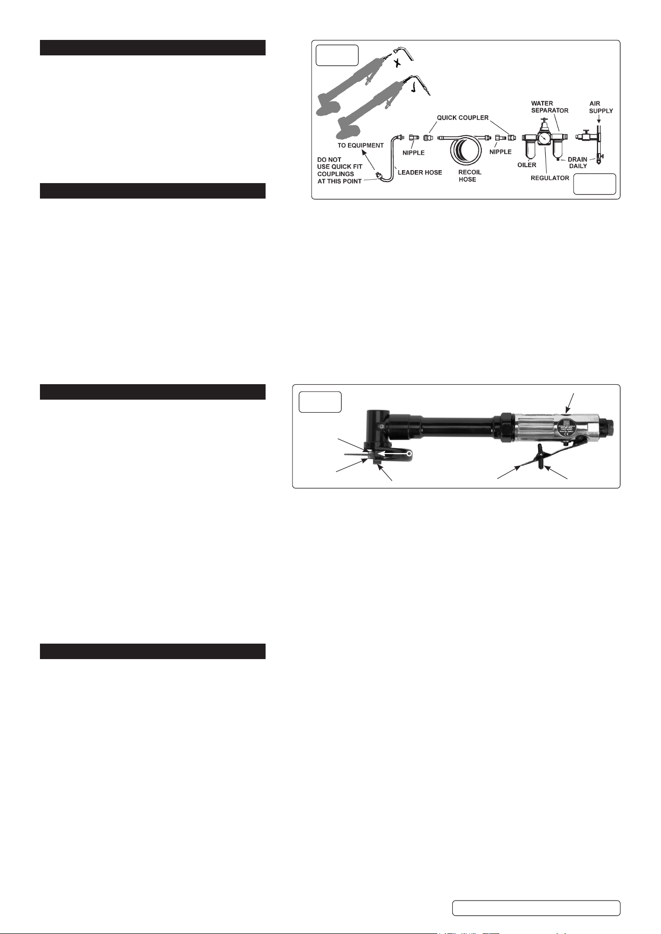
4.1. AIR SUPPLY - Recommended hook-up is shown in fig 2.
4.1.1. Ensurethatthecut-otoolairvalve(orthrottle)isinthe“o”positionbeforeconnectingtotheairsupply.
4.1.2. You will require an air pressure between 70-90psi, and an air flow according to the specification above.
4.1.3. Ensure the air supply is clean and does not exceed 90psi while operating the cut-otool.
4.1.4. Too high an air pressure and/or unclean air will cause excessive wear, and may be dangerous, causing damage and/or personal
injury.
4.1.5. Drain the air tank daily. Water in the air line will damage the cut-otool and invalidate your warranty.
4.1.6. Clean air inlet filter weekly.
4.1.7. Line pressure should be increased to compensate for unusually long air hoses (over 8 metres).
4.1.8. The minimum hose diameter should be 1/4” I.D. and fittings must have the same inside dimensions.
4.1.9. Keep hose away from heat, oil and sharp edges. Check hoses for wear, and make certain that all connections are secure.
4.2. COUPLINGS
4.2.1. Vibrationmaycausefailureifaquickchangecouplingisconnecteddirectlytothecut-otool.Topreventthis,connectaleaderhose-
SealeymodelnumberAH2RorAH2R/38-tothecut-otool.Aquickchangecouplingmaythenbeusedtoconnecttheleaderhoseto
theairlinerecoilhose.Seeg.1andg.2.
5. OPERATION
WARNING! Ensure that you read, understand and
apply the safety instructions before use.
5.1. ASSEMBLY
5.1.1. To attach the cutting disc you will need the supplied
5.1.2. pressed steel spanner and 4mm allen key, the spanner to
hold the spindle and the allen key to loosen or tighten the
socket head cap screw.
5.1.3. Fittheangewiththe11mmx0.8mmmilledsloton
tothespindle,theslotregisteringwiththespanneratsofthespindle.Placethecuttingdiscontothespindle.Placethesecondange
with the Ø14mm x 0.8mm counter bore on to the spindle with the counter bore adjacent to the cutter face. Hold the spindle by placing the
spanneronthespindlespannerats.ScrewtheM6socketheadcapscrewintothespindleandtightenthediscbetweentheangeswiththe
5mmallenkey(g.3).
5.1.4. Connectaltered,lubricatedandregulatedairsupply(g.2)tothecut-otoolandpushdownthesafetycatchandgripthecontrol
valve lever to check that the tool is working correctly.
5.2. OPERATING
8 DO NOT apply excessive pressure, let the cutting disc do the work for you. Start the tool and bring the disc to the surface to be cut evenly
and slowly. Remove the cutting disc from the work surface before stopping the tool. Regularly check the condition of the disc and
always change if worn, cracked or otherwise damaged.
8 DO NOT run the tool away from the workpiece for extended periods as this will shorten the life of the bearings.
WARNING! Use only discs with speed ratings equal to, or higher than, the speed rating of the tool.
6. MAINTENANCE
WARNING! Disconnect the tool from the air supply before changing the disc, servicing or performing maintenance. Replace or repair
damaged parts. Use genuine parts only. Unauthorised parts may be dangerous and will invalidate the warranty.
6.1. Lubricate the grinder daily with a few drops of good grade air tool oil, such as Sealey ATO/500 or ATO/1000, dripped into the air inlet
before use or dispensed automatically through an air system oiler, such as Sealey model SA106L or SA2001/L.
6.2. Clean the tool after use and change the disc when worn or damaged.
6.3. Loss of power or erratic action may be due to the following:
a) Excessive drain on the air supply. Moisture or restriction in the air line. Incorrect size or type of hose connectors. To remedy
check the air supply and follow instructions in Section 4.
b) Grit or gum deposits in the tool may also reduce performance. Flush the tool with gum solvent oil or an equal mixture of SAE
No 10 oil and kerosene. Allow to dry before use.
6.4. If you continue to experience problems, contact your local Sealey service agent.
6.5. When not in use, disconnect from air supply, clean tool and store in a safe, dry, childproof location.
fig.
1
fig.
2
Original Language Version
© Jack Sealey Limited
Safety catch
Control valve lever
Throttle valve adjustment
Direction of rotation
Slottedange
Counterboredange
Cutting disc
Soc. head cap screw
SA2501 Issue:2 (H,F) 09/10/20
fig.
3

Sealey Group, Kempson Way, Suffolk Business Park, Bury St Edmunds, Suffolk. IP32 7AR
01284 757500 01284 703534 sales@sealey.co.uk www.sealey.co.uk
ENVIRONMENT PROTECTION
Recycle unwanted materials instead of disposing of them as waste. All tools, accessories and packaging should be sorted, taken to
a recycling centre and disposed of in a manner which is compatible with the environment. When the product becomes completely
unserviceable and requires disposal, drain any fluids (if applicable) into approved containers and dispose of the product and fluids
according to local regulations.
Note: It is our policy to continually improve products and as such we reserve the right to alter data, specifications and component parts without prior
notice.
Important: No Liability is accepted for incorrect use of this product.
Warranty: Guarantee is 12 months from purchase date, proof of which is required for any claim.
Original Language Version
© Jack Sealey Limited
SA2501 Issue:2 (H,F) 09/10/20
WARNING! – Risk of Hand Arm Vibration Injury.
This tool may cause Hand Arm Vibration Syndrome if its use is not adequately managed.
This tool is subject to the vibration testing section of the Machinery Directive 2006/42/EC.
This tool is to be operated in accordance with these instructions.
This tool has been tested in accordance with: EN ISO 28927-1:2009 & BS EN ISO 15744:2008.
Declaration and verification of Vibration Emission figures are in accordance with EN 12096:1997
Measured vibration emission value (a): 2.1 m/s²
Uncertainty value(k): 0.08 m/s²
Please note that the application of the tool to a sole specialist task may produce a different average vibration emission. We recommend that a
specific evaluation of the vibration emission is conducted prior to commencing with a specialist task.
A health and safety assessment by the user (or employer) will need to be carried out to determine the suitable duration of use for each tool.
NB: Stated Vibration Emission values are type-test values and are intended to be typical.
Whilst in use, the actual value will vary considerably from and depend on many factors.
Such factors include; the operator, the task and the inserted tool or consumable.
NB: ensure that the length of leader hoses is sufficient to allow unrestricted use, as this also helps to reduce vibration.
The state of maintenance of the tool itself is also an important factor, a poorly maintained tool will also increase the risk of Hand Arm Vibration
Syndrome.
Health surveillance.
We recommend a programme of health surveillance to detect early symptoms of vibration injury so that management procedures can be modified
accordingly.
Personal protective equipment.
We are not aware of any personal protective equipment (PPE) that provides protection against vibration injury that may result from the uncontrolled
use of this tool. We recommend a sufficient supply of clothing (including gloves) to enable the operator to remain warm and dry and maintain good
blood circulation in fingers etc. Please note that the most effective protection is prevention, please refer to the Correct Use and Maintenance section
in these instructions. Guidance relating to the management of hand arm vibration can be found on the HSC website www.hse.gov.uk - Hand-Arm
Vibration at Work.