
June 2012
© 2012 Fluke Corporation. All rights reserved. Specifications are subject to change without notice.
All product names are trademarks of their respective companies.
414D/419D/424D
Laser Distance Meter
Users Manual
1.888.610.7664 sales@GlobalTestSupply.com
Fluke-Direct.com

LIMITED WARRANTY AND LIMITATION OF LIABILITY
Each Fluke product is warranted to be free from defects in material and workmanship under normal use and service. The warranty period is
three years and begins on the date of shipment. Parts, product repairs, and services are warranted for 90 days. This warranty extends only
to the original buyer or end-user customer of a Fluke authorized reseller, and does not apply to fuses, disposable batteries, or to any product
which, in Fluke's opinion, has been misused, altered, neglected, contaminated, or damaged by accident or abnormal conditions of operation
or handling. Fluke warrants that software will operate substantially in accordance with its functional specifications for 90 days and that it has
been properly recorded on non-defective media. Fluke does not warrant that software will be error free or operate without interruption.
Fluke authorized resellers shall extend this warranty on new and unused products to end-user customers only but have no authority to
extend a greater or different warranty on behalf of Fluke. Warranty support is available only if product is purchased through a Fluke
authorized sales outlet or Buyer has paid the applicable international price. Fluke reserves the right to invoice Buyer for importation costs of
repair/replacement parts when product purchased in one country is submitted for repair in another country.
Fluke's warranty obligation is limited, at Fluke's option, to refund of the purchase price, free of charge repair, or replacement of a defective
product which is returned to a Fluke authorized service center within the warranty period.
To obtain warranty service, contact your nearest Fluke authorized service center to obtain return authorization information, then send the
product to that service center, with a description of the difficulty, postage and insurance prepaid (FOB Destination). Fluke assumes no risk
for damage in transit. Following warranty repair, the product will be returned to Buyer, transportation prepaid (FOB Destination). If Fluke
determines that failure was caused by neglect, misuse, contamination, alteration, accident, or abnormal condition of operation or handling,
including overvoltage failures caused by use outside the product’s specified rating, or normal wear and tear of mechanical components,
Fluke will provide an estimate of repair costs and obtain authorization before commencing the work. Following repair, the product will be
returned to the Buyer transportation prepaid and the Buyer will be billed for the repair and return transportation charges (FOB Shipping
Point).
THIS WARRANTY IS BUYER'S SOLE AND EXCLUSIVE REMEDY AND IS IN LIEU OF ALL OTHER WARRANTIES, EXPRESS OR
IMPLIED, INCLUDING BUT NOT LIMITED TO ANY IMPLIED WARRANTY OF MERCHANTABILITY OR FITNESS FOR A PARTICULAR
PURPOSE. FLUKE SHALL NOT BE LIABLE FOR ANY SPECIAL, INDIRECT, INCIDENTAL OR CONSEQUENTIAL DAMAGES OR
LOSSES, INCLUDING LOSS OF DATA, ARISING FROM ANY CAUSE OR THEORY.
Since some countries or states do not allow limitation of the term of an implied warranty, or exclusion or limitation of incidental or
consequential damages, the limitations and exclusions of this warranty may not apply to every buyer. If any provision of this Warranty is held
invalid or unenforceable by a court or other decision-maker of competent jurisdiction, such holding will not affect the validity or enforceability
of any other provision.
11/99
1.888.610.7664 sales@GlobalTestSupply.com
Fluke-Direct.com

i
Table of Contents
Title Page
Introduction .................................................................................................................... 1
How to Contact Fluke ..................................................................................................... 1
Safety Information .......................................................................................................... 2
Electromagnetic Compatibility (EMC) ........................................................................ 3
FCC Statement (U.S.A Only) ..................................................................................... 3
Laser Classification ................................................................................................... 4
Integrated Distance Meter .................................................................................... 4
Laser Class 2 Products ......................................................................................... 4
Features ......................................................................................................................... 5
Before You Start ............................................................................................................. 6
Batteries .................................................................................................................... 6
Multifunctional Endpiece ............................................................................................ 7
Keypad ...................................................................................................................... 8
Display ....................................................................................................................... 9
Button Functions ............................................................................................................ 10
On/Off ........................................................................................................................ 10
Basics ........................................................................................................................ 10
Units of Measurement ............................................................................................... 11
Timer (419D/424D) .................................................................................................... 12
Beeper (419D/424D) ................................................................................................. 12
1.888.610.7664 sales@GlobalTestSupply.com
Fluke-Direct.com

414D/419D/424D
Users Manual
ii
Backlight (419D/424D) .............................................................................................. 12
Keypad Lock (419D/424D) ........................................................................................ 12
Compass (424D) ....................................................................................................... 13
Compass Calibration ................................................................................................. 13
Automatic Calibration ........................................................................................... 13
Manual Calibration ............................................................................................... 13
Magnetic Declination ............................................................................................ 14
Clear ......................................................................................................................... 16
Measurements with a Tripod ..................................................................................... 16
Reference Point ........................................................................................................ 16
Measurements ............................................................................................................... 17
Single Distance Measurement .................................................................................. 17
Minimum/Maximum Tracking .................................................................................... 17
Addition/Subtraction .................................................................................................. 18
Area .......................................................................................................................... 18
Volume ...................................................................................................................... 19
Tilt (424D only) .......................................................................................................... 20
Smart Horizontal Mode (424D only) ..................................................................... 20
Height Tracking (424D only) ................................................................................. 20
Leveling ................................................................................................................ 21
Tilt Sensor Calibration .......................................................................................... 22
Stake Out Measurement (419D/424D) ...................................................................... 23
Corner Angle Measurement (424D only) .................................................................. 25
Indirect Measurement ............................................................................................... 26
Memory (419D/424D) .................................................................................................... 29
Maintenance .................................................................................................................. 29
Disable the Meter ........................................................................................................... 29
Message codes ............................................................................................................. 30
Specifications ................................................................................................................ 31
1.888.610.7664 sales@GlobalTestSupply.com
Fluke-Direct.com

iii
List of Tables
Table Title Page
1. Symbols ................................................................................................................................. 2
2. Model Feature Comparison ................................................................................................... 5
3. Units of Measurement ........................................................................................................... 11
4. Estimated Values of Magnetic Field ...................................................................................... 15
5. Message Codes .................................................................................................................... 30
1.888.610.7664 sales@GlobalTestSupply.com
Fluke-Direct.com

1
Laser Distance Meter
Introduction
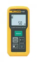
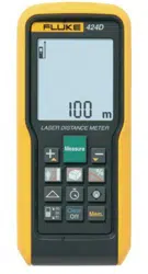
The Fluke 414D/419D/424D Laser Distance Meters
(Meter or Product) are professional-grade laser distance
meters. Use these Meters to quickly and accurately get
the distance to a target, the area, and the volume
measurements.
This Meter is better than an ultrasonic device because it
uses laser light waves and measures their reflection. The
Meter includes:
• Most advanced technology for distance
measurements
• More accurate measurement
• Longer measurement distance – model dependent
This manual identifies when a feature is
model-dependent. If not identified, all models include the
feature.
1.888.610.7664 sales@GlobalTestSupply.com
Fluke-Direct.com

414D/419D/424D
Users Manual
2
Safety Information
A Warning identifies hazardous conditions and
procedures that are dangerous to the user. A Caution
identifies the conditions and procedures that can cause
damage to the Product or cause permanent loss of data.
W* Warning
To prevent eye damage and personal injury, do
not look into the laser. Do not point the laser
directly at persons or animals or indirectly off
reflective surfaces.
W Warning
To prevent personal injury:
• Read all safety information before you use the
Product.
• Carefully read all instructions.
• Use the Product only as specified, or the
protection supplied by the Product can be
compromised.
• Replace the batteries when the low battery
indicator shows to prevent incorrect
measurements.
• Do not use the Product around explosive gas.
• Do not use the Product if it operates
incorrectly.
• Do not use and disable the Product if it is
damaged.
Table 1 is a list of symbols used on the Product and in
this manual.
Table 1. Symbols
Symbol Description
Battery status.
M
Battery or battery compartment.
W
Important information. See manual.
*
Warning. Laser.
Conforms to relevant Australian standards.
P
Conforms to requirements of European
Union and European Free Trade
Association.
~
Do not dispose of this product as unsorted
municipal waste. Go to Fluke's website for
recycling information.
1.888.610.7664 sales@GlobalTestSupply.com
Fluke-Direct.com

Laser Distance Meter
Safety Information
3
Electromagnetic Compatibility (EMC)
The term "electromagnetic compatibility" identifies that the
Product operates smoothly in an environment where
electromagnetic radiation and electrostatic discharges are
present and does not cause electromagnetic interference
to other equipment.
W Warning
The Product conforms to the most stringent
requirements of the relevant standards and
regulations. Yet, the possibility that it causes
interference in other devices cannot be
totally excluded.
W Caution
Never repair the Product yourself.
FCC Statement (U.S.A Only)
This equipment has been tested and found to comply with
the limits for a Class B digital device, pursuant to part 15
of the FCC Rules. These limits are designed to provide
reasonable protection against harmful interference in a
residential installation.
This equipment generates, uses, and can radiate radio
frequency energy and, if not installed and used in
accordance with the instructions, may cause harmful
interference to radio communications.
However, there is no guarantee that interference will not
occur in a particular installation.
If this equipment does cause harmful interference to radio
or television reception, which can be determined by
turning the equipment off and on, the user is encouraged
to try to correct the interference with one or more of these
measures:
• Reorient or relocate the receiving antenna.
• Increase the separation between the equipment and
receiver.
• Connect the equipment into an outlet on a circuit
different from that to which the receiver is connected.
• Consult the dealer or an experienced radio/TV
technician for help.
W Warning
Changes or modifications not expressly
approved by Fluke for compliance could void
the user’s authority to operate the
equipment.
1.888.610.7664 sales@GlobalTestSupply.com
Fluke-Direct.com
414D/419D/424D
Users Manual
4
Laser Classification
Integrated Distance Meter
The Meter produces a visible laser beam from the front of
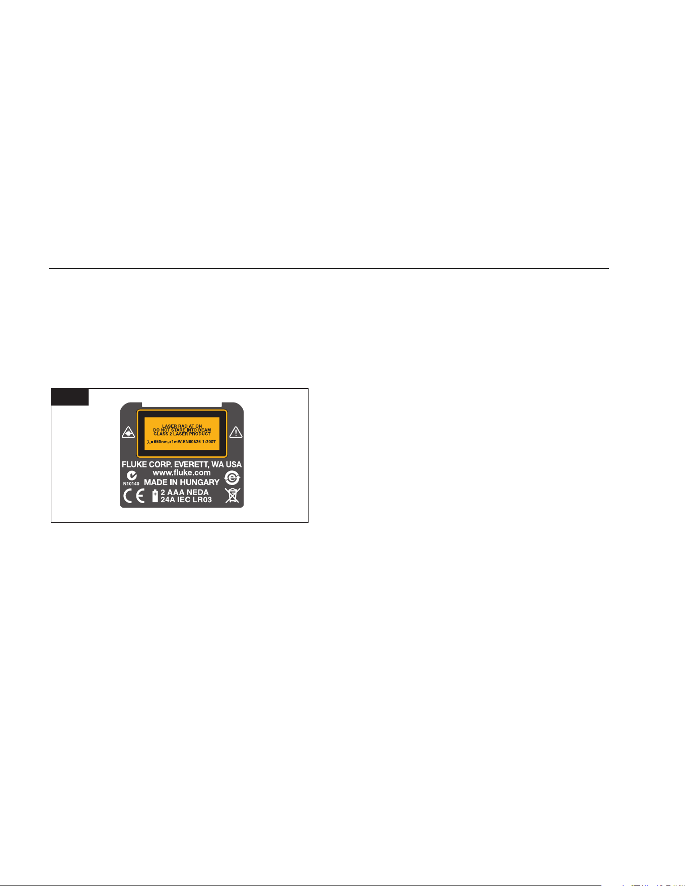
the Meter. Figure 1 shows the warning that is on the back
of the Meter.
It is a Class 2 laser product in accordance with
IEC60825-1 : 2007 “Radiation safety of laser products.”
1
gwo20.gif
Laser Class 2 Products
Do not stare into the laser beam or direct it towards other
people unnecessarily. Eye protection is normally afforded
by aversion responses including the blink reflex.
*W Warning
Do not look directly into the beam with
optical aids. Looking directly into the beam
with optical aids (for example, binoculars and
telescopes) can be hazardous.
W Caution
Looking into the laser beam may be
hazardous to the eyes.
Do not look into the laser beam. Make sure the laser is
pointed above or below eye level, particularly with fixed
installations in machines and similar setups.
1.888.610.7664 sales@GlobalTestSupply.com
Fluke-Direct.com

Laser Distance Meter
Features
5
Features
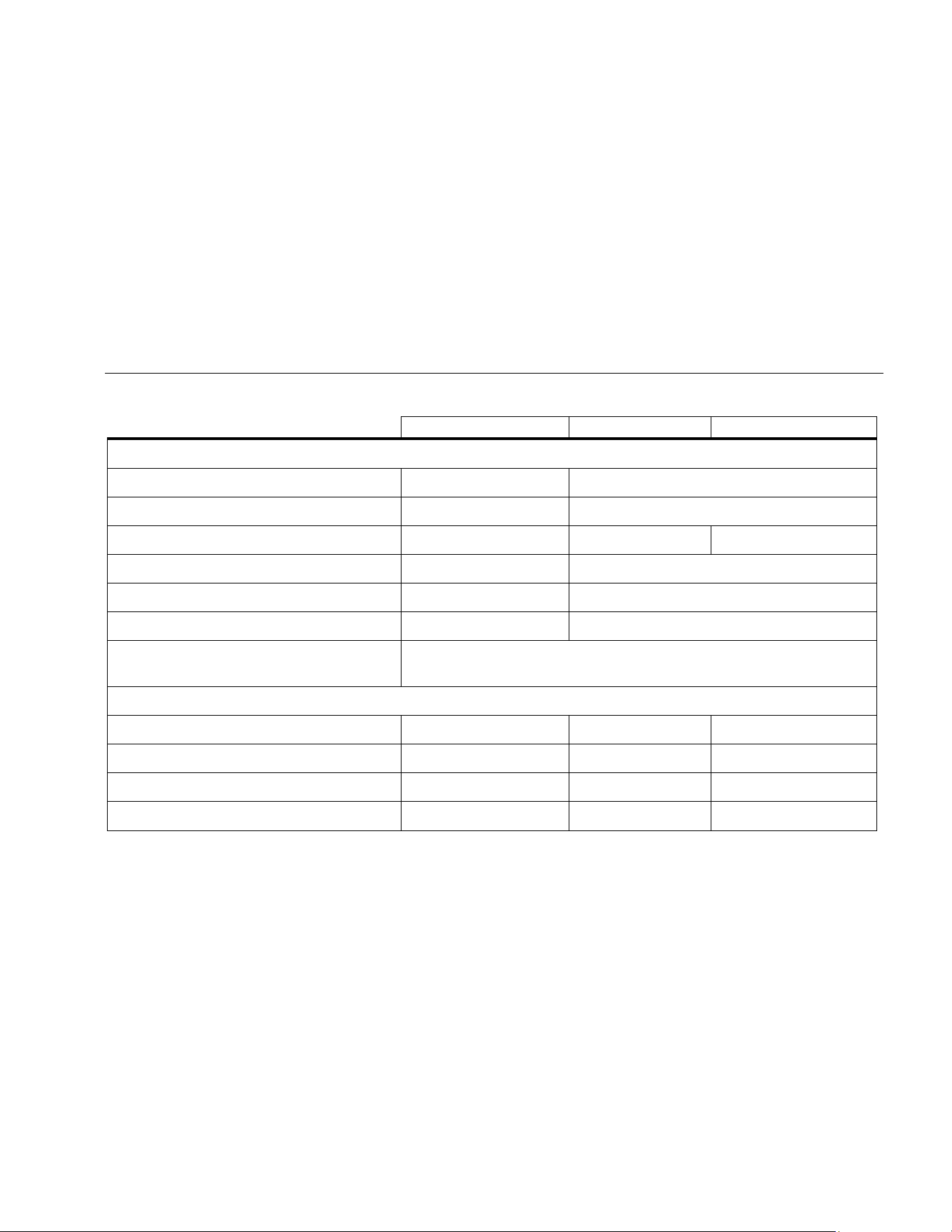
Table 2 is a list of features for the Meter by model.
Table 2. Model Feature Comparison
Feature 414D 419D 424D Feature 414D 419D 424D
Display Lines 2 3 4 Timer • •
Memory
[1]
20 20 Display/Keypad Illumination • •
Add/Subtract • • • Keypad Lock • •
Area • • • Tripod Measurement • •
Volume • • • Compass •
Continuous Measurement • • Triangular Area •
Pythagoras Calculations 1+2 Full Full Smart Horizontal Mode (Tilt) •
Stake Out
[2]
• • Height Tracking •
Multifunction Endpiece • • Room Corner Angle •
Beeper • • Handstrap • • •
[1] 419D and 424D store a maximum of 20 complete display readouts.
[2] 419D uses 1 value. 424D uses 2 values.
1.888.610.7664 sales@GlobalTestSupply.com
Fluke-Direct.com
414D/419D/424D
Users Manual
6
Before You Start
This section has basic information about the batteries and
measurement reference point. It also describes the Meter
keypad and display.
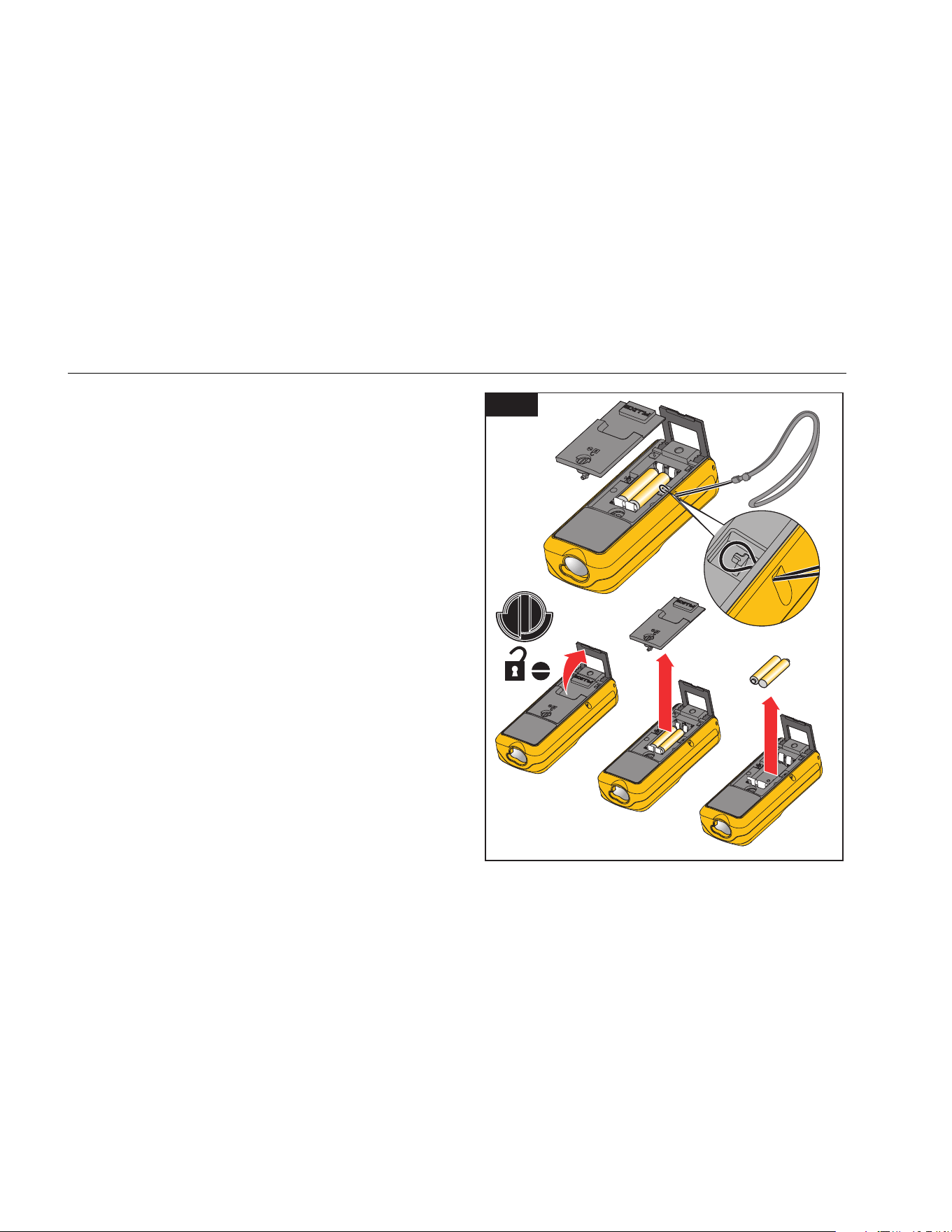
Batteries
Replace the batteries when blinks in the display.
To install or replace the batteries:
1. Remove battery compartment lid. See Figure 2.
2. Attach the handstrap.
3. Install two AAA (LR03) batteries with the correct
polarity.
Note
Do not use zinc-carbon batteries.
4. Close the battery compartment.
W Caution
To prevent corrosion, remove the batteries
before a long period of nonuse.
2
gwo01.eps
1.888.610.7664 sales@GlobalTestSupply.com
Fluke-Direct.com
Laser Distance Meter
Before You Start
7
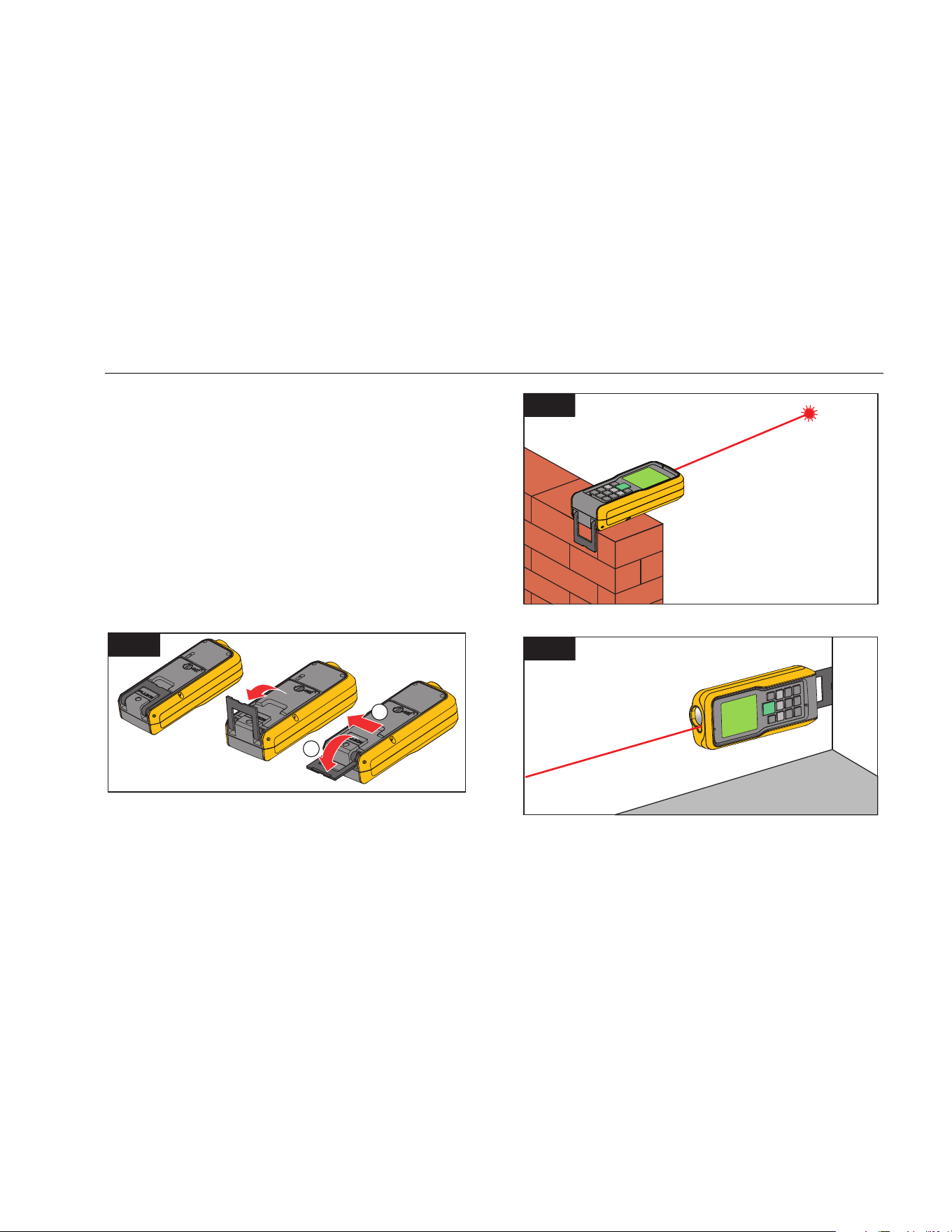
Multifunctional Endpiece
The 419D and 424D Meters adapt to multiple
measurement situations with the multifunctional endpiece,
see Figure 3:
• For measurements from an edge, fold out the
endpiece (90 °) until it locks into place. See Figure 4.
• For measurements from a corner, fold out the
endpiece (90 °) until it locks into place. Push the
endpiece lightly to the right side to fold it out fully.
See Figures 3 and 5.
• A built-in sensor automatically senses the orientation
of the endpiece and adjusts the zero point.
3
1
2
gwo02.eps
4
gwo03.eps
5
gwo04.eps
1.888.610.7664 sales@GlobalTestSupply.com
Fluke-Direct.com
414D/419D/424D
Users Manual
8
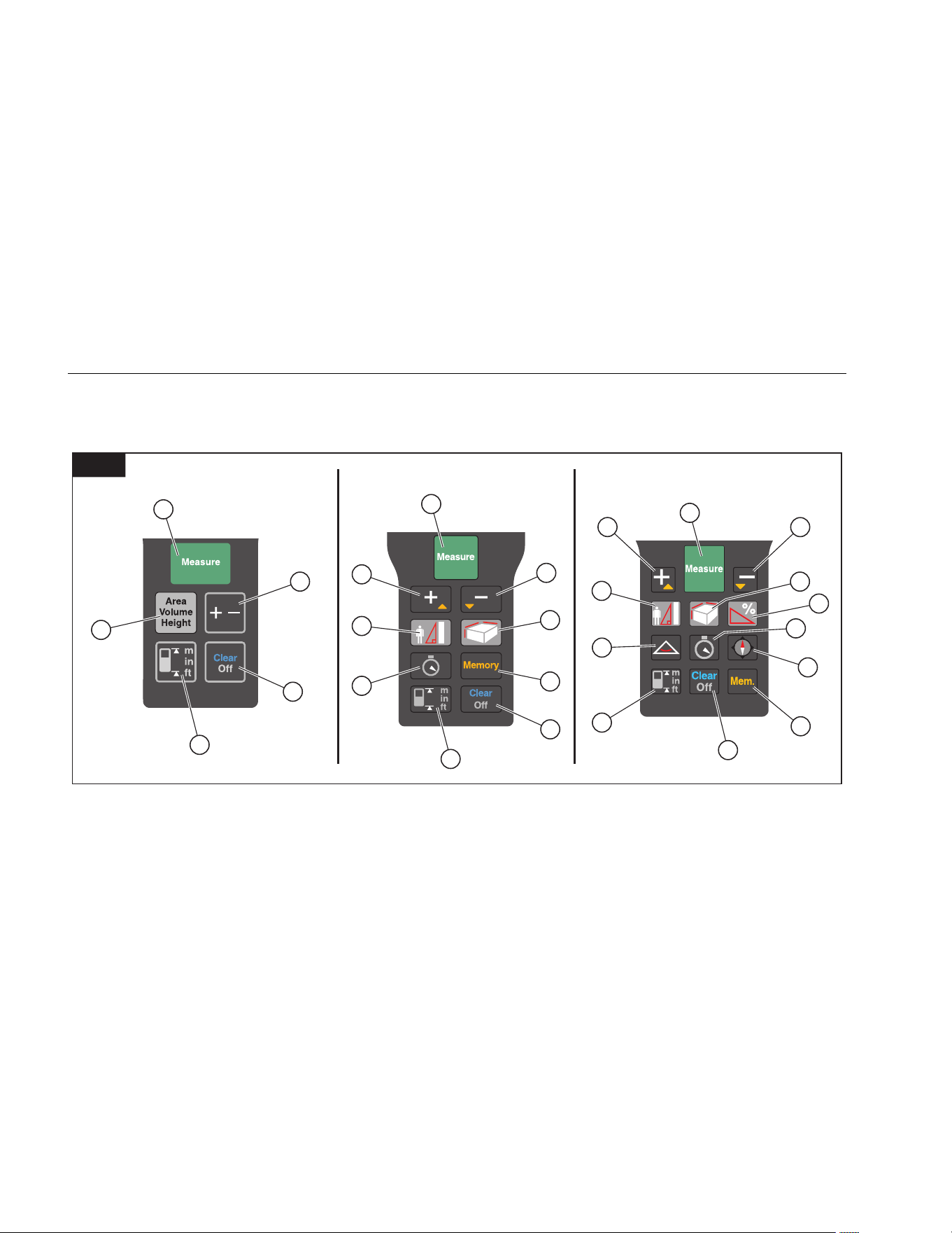
Keypad
Figure 6 shows the location of each function button on
the keypad.
1
1
1
3
2
4
3
8
11
4
9
12
5
5
6
6
7
14
10
10
9
5
6
13
8
11
6
424D419D414D
gwo05.eps
Measure/Power On Clear/Off Area/Volume Triangle
Plus (+)/Minus (-) Reference/Change Units Memory Compass
Plus (+)/Scroll Up Area/Volume/Indirect Measurement (Pythagoras) Timer
Minus (-)/Scroll Down Indirect Measurement (Pythagoras and Stake Out) Tilt
1.888.610.7664 sales@GlobalTestSupply.com
Fluke-Direct.com
Laser Distance Meter
Before You Start
9
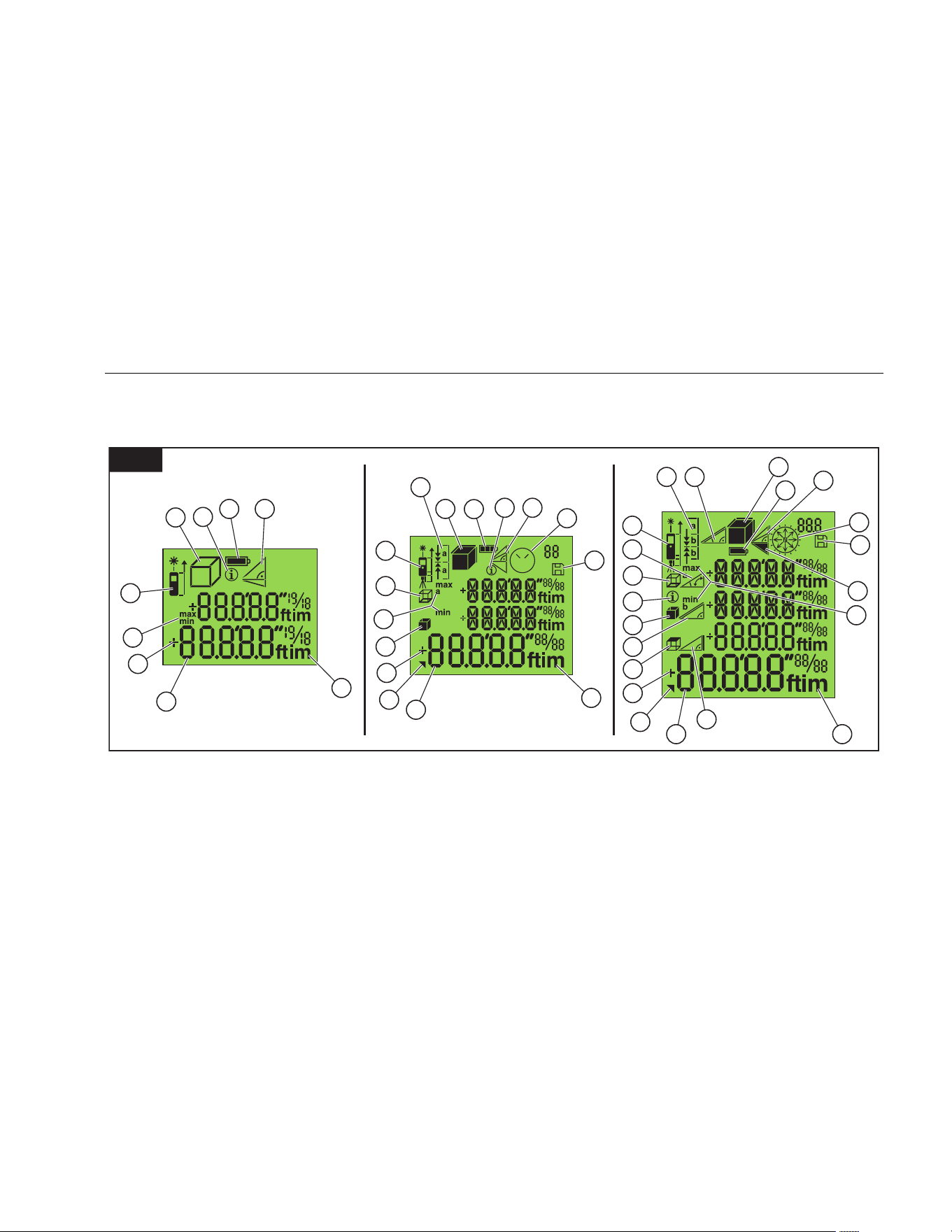
Display
Figure 7 shows the readout location on the display for
each function.
7
1 8
5
7
7
6
4
4
10
11
5
6
13
12
9
2
2 8
1
3
14
3
14 20
1
3
8
6
13
7
19
9
5
21
4
15
2
11
18
16
12
10
424D419D414D
17
12
19
gwo06.eps
Battery Status Units of Measurement 2
nd
Result Available Timer/Compass (424D only)
Info Pythagoras Stake Out Leveling
Area/Volume Memory Tilt Angle Triangle Area
Measurement Reference Circumference Slope Distance
Min/Max Measurement (Tracking Mode) Wall Area Indirect Height
Measurement Readout Addition/Subtraction Ceiling Area
1.888.610.7664 sales@GlobalTestSupply.com
Fluke-Direct.com

414D/419D/424D
Users Manual
10
Button Functions
This section is about how to use the buttons and identifies
when a function is model-dependent. When not identified,
all models include the function.
On/Off
Push to turn on the Meter and laser. The display
shows the battery symbol until you push a different
button.
Push for 2 seconds to turn off the meter.
Note
The Meter turns off automatically if not used in
180 seconds.
Basics
414D
Measure Button
Push
:
• 1x = Laser on
• 2x = Measure
In Pythagoras calculation mode:
• 2 seconds = Tracking (min/max measurement)
Function Buttons
Push
:
• 1x = Area
• 2x = Volume
• 3x = Pythagoras 1
• 4x = Pythagoras 2
419D/424D
Measure Button
When off, push for 2 seconds = Continuous Laser On
Push :
• 1x = Laser On
• 2x = Measure
• 2 seconds = Tracking (min/max measurement)
Function Buttons
Push
:
• 1x = Pythagoras 1
• 2x = Pythagoras 2
• 3x = Pythagoras 3
• 4x = Stake Out (419D: 1 value / 424D: 2 values)
1.888.610.7664 sales@GlobalTestSupply.com
Fluke-Direct.com

Laser Distance Meter
Button Functions
11
Push :
• 1x = Area
• 2x = Volume
• 2 seconds = 2
nd
Results
424D Only
Push :
• 1x = Smart Horizontal Mode
• 2x = Height Tracking
• 3x = Leveling
Push
:
• 1x = Room Corner Angle (Triangular Area)
• 2 seconds = 2
nd
Results
Units of Measurement
Push and hold (414D) or (419D/424D) for
2 seconds to toggle between the units for distance
measurements, see Table 3.
Table 3. Units of Measurement
414D
419D/424D
0.000 m 0.000 m
0 00″ 1/16* 0.000
0
m
0 in 1/16 0.00 m
* Default 0.00 ft
0′00″
1/32
*
0.000 in
0 in
1/32
* Default
1.888.610.7664 sales@GlobalTestSupply.com
Fluke-Direct.com

414D/419D/424D
Users Manual
12
Timer (419D/424D)
Fluke recommends that you use a time-delay for the most
accurate measurements at long distances. This prevents
Meter movement when you push
.
To turn on the timer:
1. Push
1x to turn on the 5-second timer. This is the
default time interval to release the laser for a
measurement.
2. Push
to increase up to 60 seconds.
3. Push
to decrease the seconds.
4. Push to begin the timer.
The seconds until measurement (for example, 59,
58, 57...) show as a countdown. The last 5 seconds
count down with a beep. After the last beep, the
Meter makes the measurement and the value shows
on the display.
Note
The timer is useful for all measurements.
Beeper (419D/424D)
Push at the same time for 2 seconds to turn on
and turn off the beeper. The display shows the status as
or .
Backlight (419D/424D)
Push at the same time for 2 seconds to turn on
and turn off the backlight. The display shows the status
as or .
Keypad Lock (419D/424D)
To lock:
1. Push at the same time to lock the keypad.
To unlock:
1. Push .
2. Push within 2 seconds to unlock the keypad.
1.888.610.7664 sales@GlobalTestSupply.com
Fluke-Direct.com

Laser Distance Meter
Button Functions
13
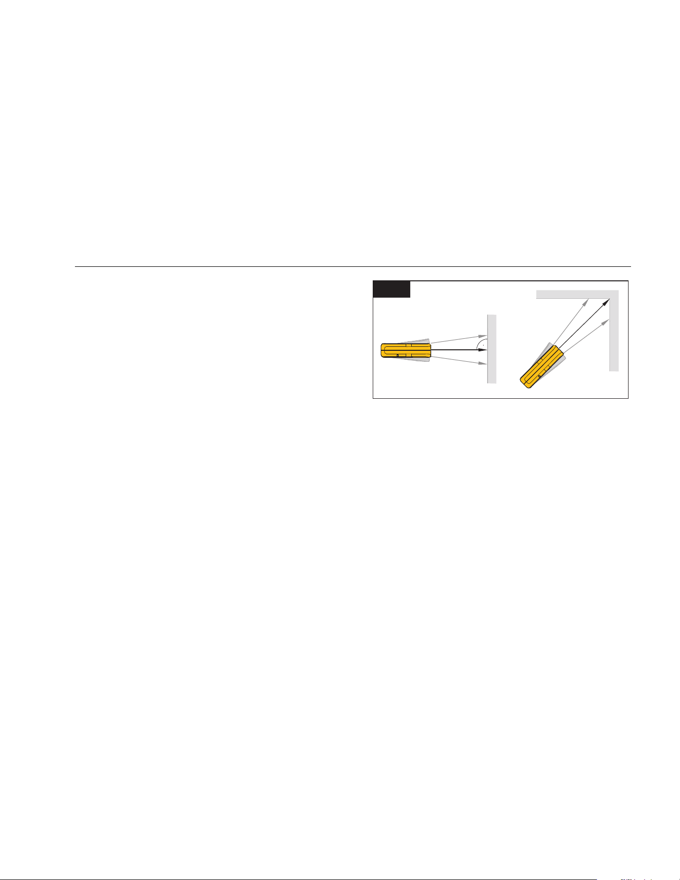
Compass (424D)
The compass feature lets you know the view or direction
as you make measurements. This is useful indoors to set
the building plans in the correct direction. It is also useful
to know the correct direction when you calculate the
efficiency for a solar panel.
Tips:
• Make sure that the endpiece is folded in.
• When you use the compass feature, the Meter shows
the calibration message. See Compass Calibration for
more information.
• Compass arrows blink on the display if the Meter is
tilted >20 ° end to end or >10 ° side to side.
• When you turn on the compass, the Meter shows the
calibration message. See Manual Calibration for more
information.
Push
:
• 1x = Arrow points in north direction
• 2 seconds = Arrow points in direction of Laser beam
and display shows the direction in degrees and an
alpha symbol.
W Caution
To prevent incorrect direction readouts, do
not use near magnets and magnetic devices.
Compass Calibration
Automatic Calibration
The compass sensor continuously collects and saves
new calibration values in 60-second intervals.
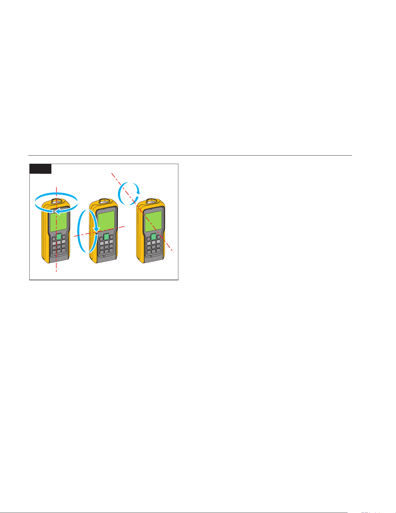
Manual Calibration
When you turn on the compass, the Meter shows the
calibration message:
1. For no, push
. The compass uses old data that
can be inaccurate.
2. For yes, push
.
To continue with the calibration:
3. Rotate the Meter 180 ° around the Z-axis. See
Figure 8.
4. Rotate the Meter 180 ° around the X-axis.
5. Rotate the Meter 180 ° around the Y-axis.
The Meter counts from 1 to 12 during calibration.
shows on the display when the calibration
is complete.
1.888.610.7664 sales@GlobalTestSupply.com
Fluke-Direct.com
414D/419D/424D
Users Manual
14
Z
X
Y
180°
180°
180°
8
gwo22.eps
Magnetic Declination
The difference between the north geographic pole and
the north magnetic pole is known as magnetic declination,
or more plainly, declination. The angle of declination is
different at different locations on the earth. The
geographic and magnetic poles are aligned so declination
is minimal. From some locations, the angle between the
two poles can be fairly large.
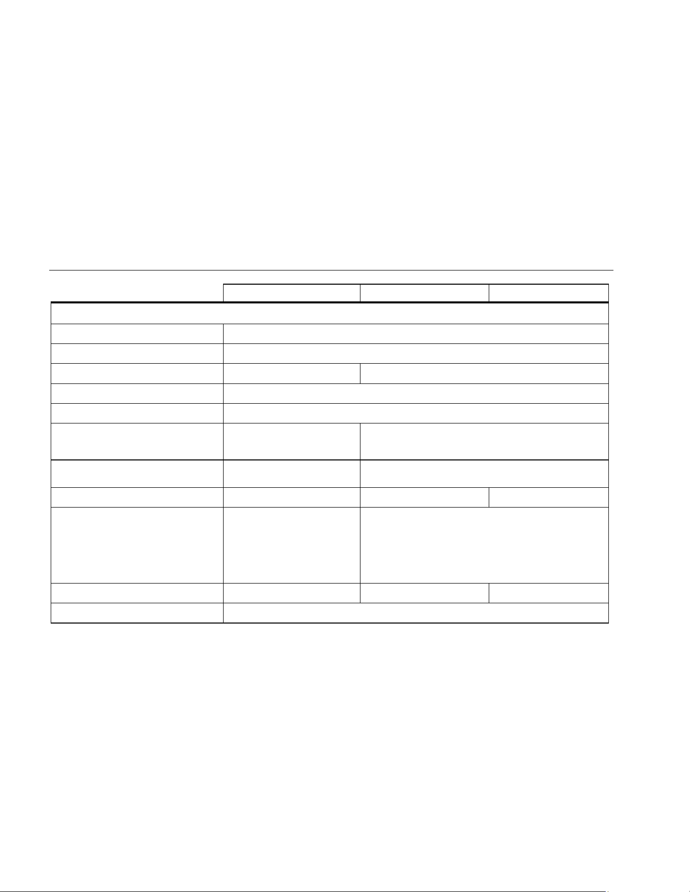
Table 4 is a list of the current angles of declination by
location. For other declination values, contact your local
Geomagnetic Institute.
To set the Meter with the correct compensation for your
location:
1. Push
at the same time.
The display shows and the current setting. The
default value is 0 °.
2. Push
and to change the value.
3. Push to accept the new value.
1.888.610.7664 sales@GlobalTestSupply.com
Fluke-Direct.com

Laser Distance Meter
Button Functions
15
Table 4. Estimated Values of Magnetic Field
Country City
Declination
in Degrees
(+E | -W)
Country City
Declination
in Degrees
(+E | -W)
Country City
Declination
in Degrees
(+E | -W)
Argentina Buenos Aires -7 Greenland Godthab -29 Spain Madrid -1
Australia Darwin 3 Iceland Reykjavik -15 Switzerland Zurich 1
Australia Perth -1 Italy Rome 2 Thailand Bangkok 0
Australia Sidney 12 India Mumbai 0 Ukraine Donetsk 7
Austria Vienna 3 Japan Tokyo -7 UAE Dubai 1
Brazil Brasilia -20 Kenya Nairobi 0 United Kingdom London -1
Brazil Rio de Janeiro -22 Norway Oslo 2 USA Anchorage 18
Canada, BC Vancouver 17 Panama Panama -3 USA Dallas 3
Chili Santiago de Chile 2 Russia Irkutsk -3 USA Denver 8
China Beijing -6 Russia Moscow 10 USA Honolulu 9
Egypt Cairo 3 Russia Omsk 11 USA Los Angeles 12
France Paris 0 Senegal Dakar -8 USA Miami -6
Germany Berlin 2 Singapore Singapore 0 USA New York -13
Greece Athens 3 South Africa Cape Town -24 Venezuela Caracas -11
1.888.610.7664 sales@GlobalTestSupply.com
Fluke-Direct.com
414D/419D/424D
Users Manual
16
Clear
Push :
• 1x = Clear last value
• 2x = Clear all
• 2 seconds = Turn off Meter
Measurements with a Tripod
Measurements with the 419D and 424D that use a tripod
must have the tripod reference set. When set,
shows on
the display.
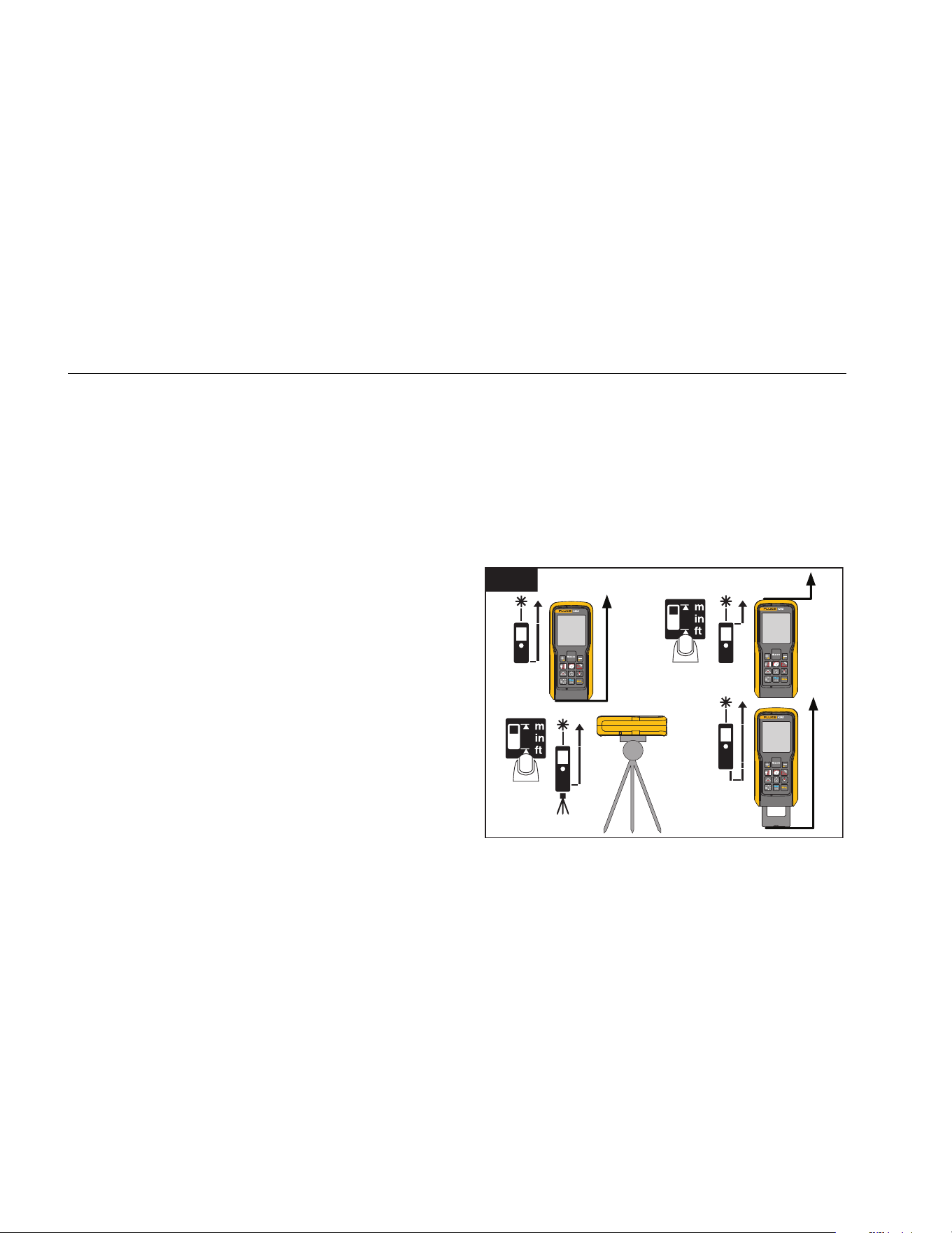
Reference Point
The display shows the reference point for a
measurement. The default reference point is from the end
of the Meter. If the beeper is on, the Meter beeps as you
change the reference point. See Figure 9 for more
information.
414D
Push 1x to change the reference point between the
front and the end of the Meter. The display shows
or .
419D/424D
The Meter automatically adjusts the reference point when
you use the endpiece and
shows on the display.
Push
:
• 1x = Measure from front
• 2x =
Measure from tripod screw
• 3x =
Measure from end
Note
T
he tripod mode overrides other reference
points. The Meter stays in the tripod mode until
you change to a different reference point.
1x
2x
Default
Auto-detect
9
gwo07.eps
1.888.610.7664 sales@GlobalTestSupply.com
Fluke-Direct.com
Laser Distance Meter
Measurements
17
Measurements
The Meter measures the distance to a target, the area
bounded by two distances, or the volume in three
measurements. This manual identifies when a feature is
model-dependent. When not identified, all models include
the feature.
Single Distance Measurement
To measure distance:
1. Push
to turn on the laser.
2. Push again to make the distance measurement.
The measurement shows on the display.
Note
Measurement errors can occur if you point the
laser at colorless liquids, glass, Styrofoam,
semi-permeable surfaces, and high-gloss
surfaces. The measurement time increases
when you point the laser at dark surfaces.
A target plate is useful for long distance measurements if
the target reflectivity and illumination is a problem.
Minimum/Maximum Tracking
The tracking function measures the room diagonal
(maximum value) and the horizontal distance (minimum
value) from a stable measurement point. It also can find
the distance between objects. See Figure 10.
Min. Max.
10
gwo08.eps
To measure:
1. Push and hold for 2 seconds.
shows on the display to confirm that the Meter is
in tracking mode.
2. Move the laser side to side, up and down on the
target area (for example, into the corner of a room).
3. Push
to stop tracking mode.
The last measured value shows in the summary line.
Note
419D/424D Only: The values for maximum and
minimum distances show in the display. The last
measured value shows in the summary line.
1.888.610.7664 sales@GlobalTestSupply.com
Fluke-Direct.com

414D/419D/424D
Users Manual
18
Addition/Subtraction
The Meter adds and subtracts a value to a single
distance, area, and volume measurements.
414D
To add or subtract:
Push :
• 1x = Add the next measurement
• 2x = Subtract the next measurement
419D/424D
To add or subtract:
1. Push
to add the next measurement to the
previous measurement.
2. Push
to subtract the next measurement from the
previous measurement.
3. Do these steps again for each measurement.
The total measurement result is always shown in the
summary line with the value before in the second
line.
4. Push
to cancel the last step.
Area
To measure area:
414D
1. Push 1x. The symbol appears in the display.
2. Push to make the first measurement (for
example, length).
3. Push
again to make the second measurement
(for example, width).
The result shows in the summary line.
419D/424D
To measure area:
1. Push 1x. The t symbol shows in the display.
2. Push to make the first measurement (for
example, length).
3. Push
again to make the second measurement
(for example, width).
The result shows in the summary line.
4. Push
and hold for 2 seconds to get the 2
nd
result
as a circumference.
1.888.610.7664 sales@GlobalTestSupply.com
Fluke-Direct.com

Laser Distance Meter
Measurements
19
Volume
414D
To measure volume:
1. Push
2x. The symbol shows in the display.
2. Push to make the first length measurement (for
example, length).
3. Push
again to make the second length
measurement (for example, width).
4. Push
again to make the third length
measurement (for example, depth).
The result displays in the summary line.
419D/424D
To measure volume:
1. Push 2x. The s symbol appears in the display.
2. Push to make the first measurement (for
example, length).
3. Push
again to make the second measurement
(for example, height).
4. Push
again to make the third length
measurement (for example, depth).
The result shows in the summary line.
5. Push x 2 seconds to show additional room
information such as ceiling/floor area, surface area of
the walls, circumference.
w Ceiling/floor area (424D)
v Wall area (419/424)
u Circumference (419D/424D)
1.888.610.7664 sales@GlobalTestSupply.com
Fluke-Direct.com
414D/419D/424D
Users Manual
20
Tilt (424D only)
Note
The inclinometer senses tilts at 360 °. For tilt
measurements, hold the Meter without a
transverse tilt (±10 °).
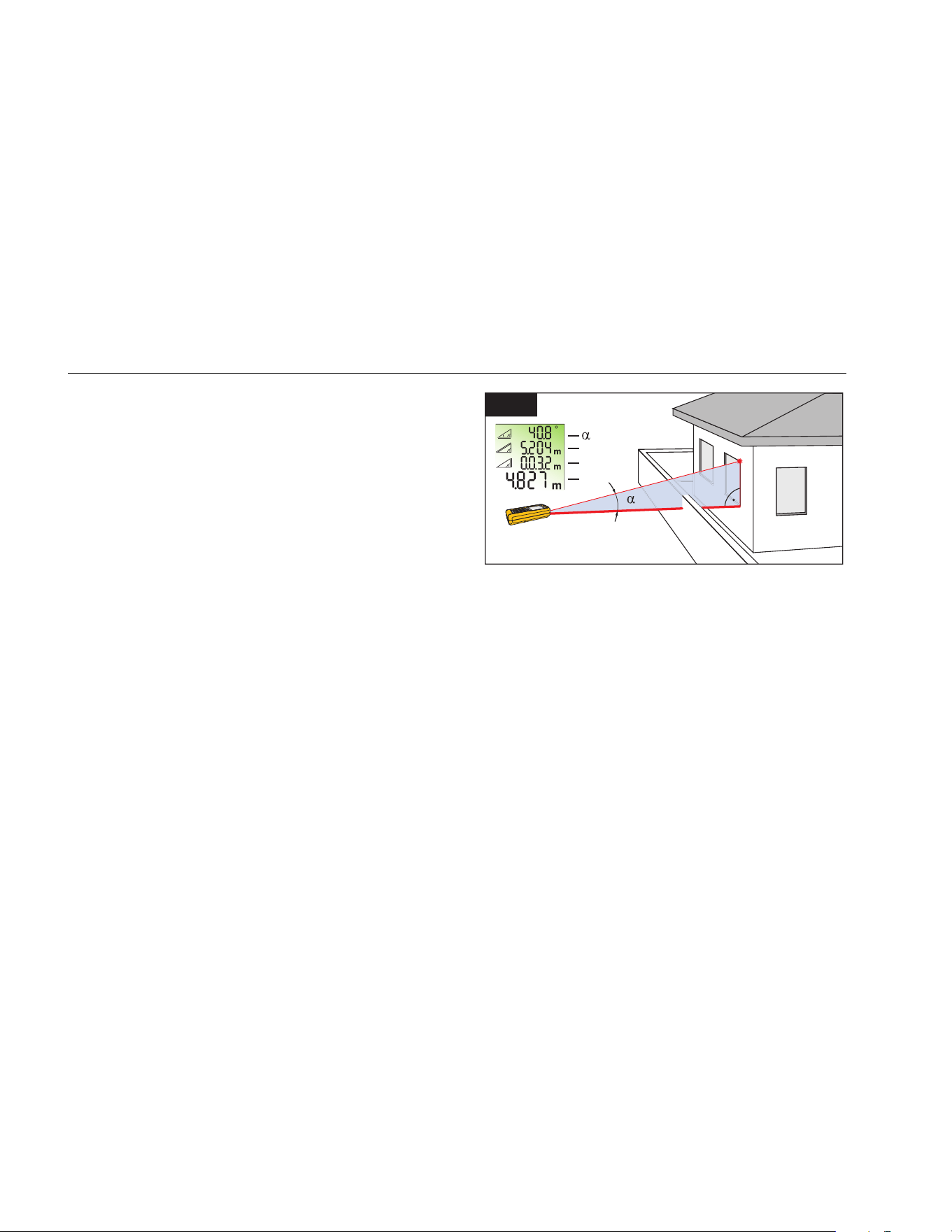
Smart Horizontal Mode (424D only)
The Smart Horizontal mode (indirect horizontal distance)
function lets you find a horizontal distance when the
line-of-sight is blocked by an object or obstacle. See
Figure 11 for more information.
The tilt is continuously shown as ° or %. To change the
units, push and hold
at the same time for
2 seconds. The default unit is °.
To measure:
1. Push
1x = Smart Horizontal Mode. ` shows in
the display.
2. Point laser at target.
3. Push
. The display shows all results as α (angle
), x (diagonal distance ), and y (vertical distance
). The z (horizontal distance) shows in the
summary line.
4. Push
to turn off Smart Horizontal Mode.
11
Z
X
Y
X
Y
Z
gwo09.eps
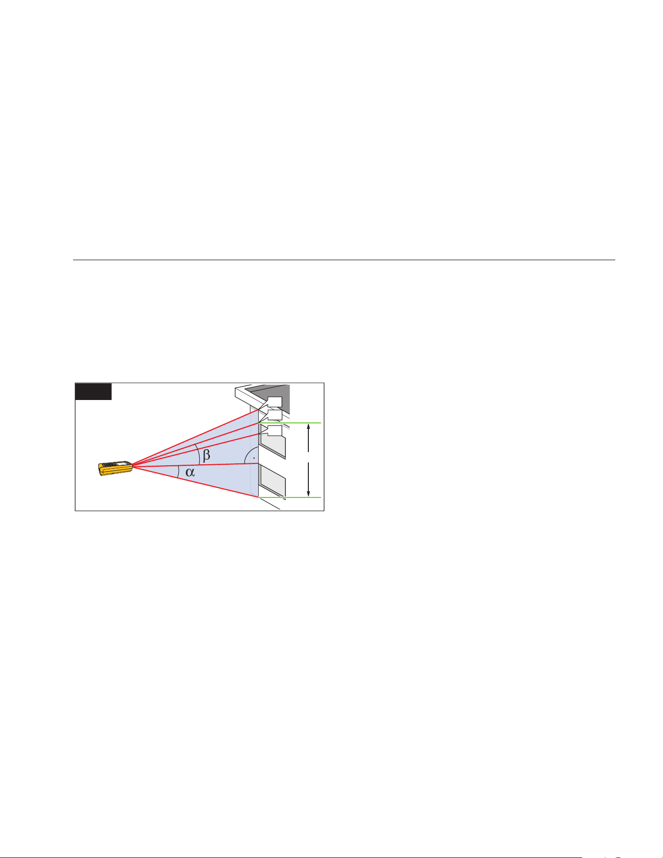
Height Tracking (424D only)
Height tracking shows continuously on the display as the
Meter turns on a tripod. The tilt is continuously shown in
the selected unit of measure as ° or %.
To measure:
1. Push
2x = Height tracking. shows in the
display.
2. Point the laser at lower target.
3. Push . shows in the display with the distance
and angle to the lower target.
4. Move the laser upwards to the top target. Height
Tracking starts automatically. The display shows the
angle to the actual target and the vertical distance
from the lower target.
1.888.610.7664 sales@GlobalTestSupply.com
Fluke-Direct.com
Laser Distance Meter
Measurements
21
5. Push at the top target. Height Tracking stops
and the display shows the vertical distance between
the two measured targets. See Figure 12 for more
information.
Note
The minimum/maximum tracking is very helpful
for 90 ° angle measurements. See page 17 for
more information.
h3
h1
X
Y
h2
12
gwo10.eps
Leveling
The Leveling function continuously shows the angle of the
Meter. From an angle of ±5 °, the Meter starts to beep. As
it gets near ±1 °, the Meter beeps faster. At ±0.3 °, the
Meter beeps constantly.
To level:
1. Push
3x = Leveling. shows in the display.
2. Put the Meter on object to do a test for level.
The angle continuously shows on the display as the
object moves.
1.888.610.7664 sales@GlobalTestSupply.com
Fluke-Direct.com
414D/419D/424D
Users Manual
22
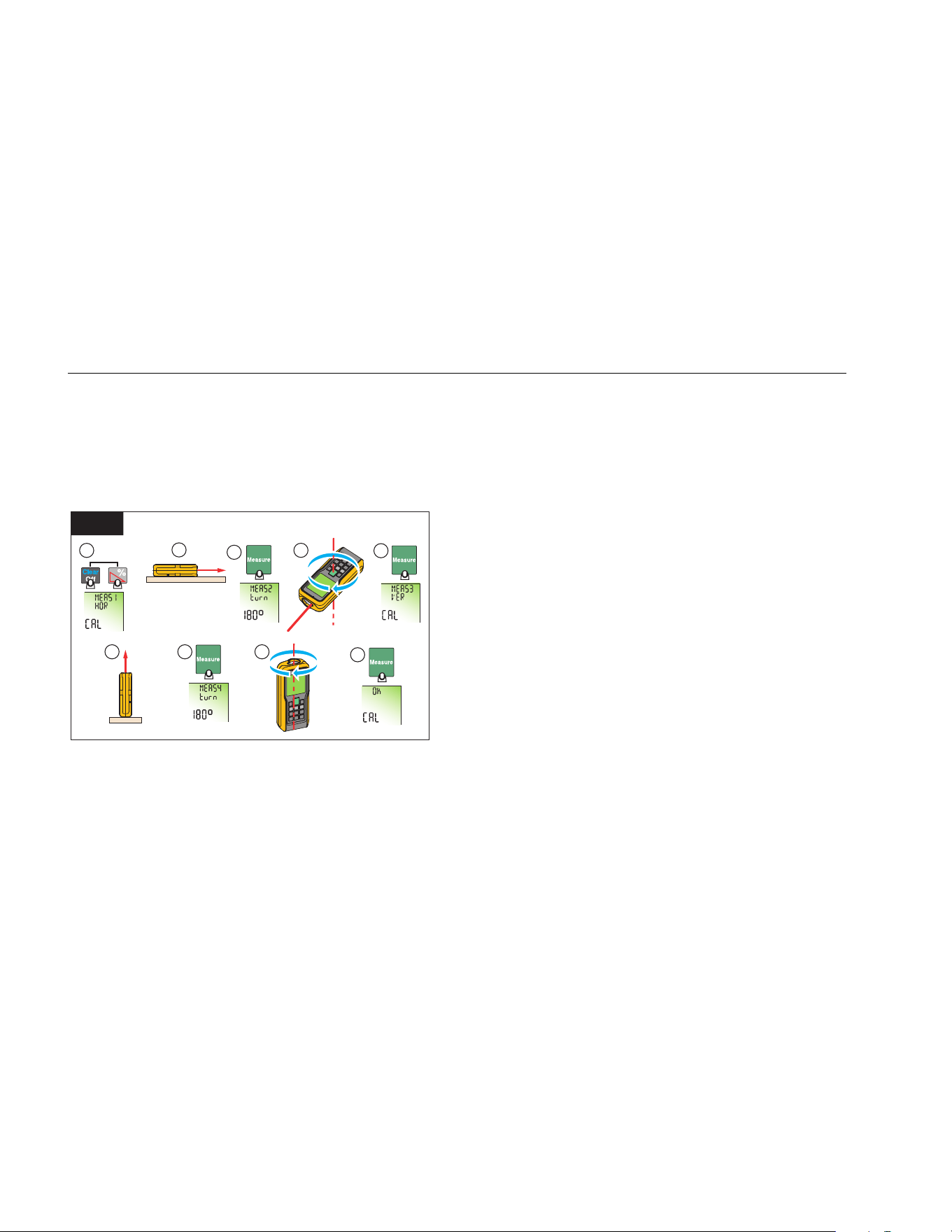
Tilt Sensor Calibration
To calibrate the tilt sensor:
1. Push at the same time for 2 seconds.
The display shows message and the instructions
for the first measurement. See Figure 13.
2 Sec.
1
2
3
4
7 8
5
6
9
13
180°
gwo23.eps
2. Put the Meter on a flat horizontal surface.
3. Push
.
The display shows the instructions for the
subsequent measurement.
4. Turn the Meter horizontally 180 ° on the same flat
horizontal surface.
5. Push
.
The display shows the instructions for the
subsequent measurement.
6. Put the Meter upright on a flat horizontal surface.
7. Push
.
The display shows the instructions for the
subsequent measurement.
8. Turn the upright Meter 180 ° on the same flat
surface.
9. Push .
The display shows the calibration results as .
1.888.610.7664 sales@GlobalTestSupply.com
Fluke-Direct.com
Laser Distance Meter
Measurements
23
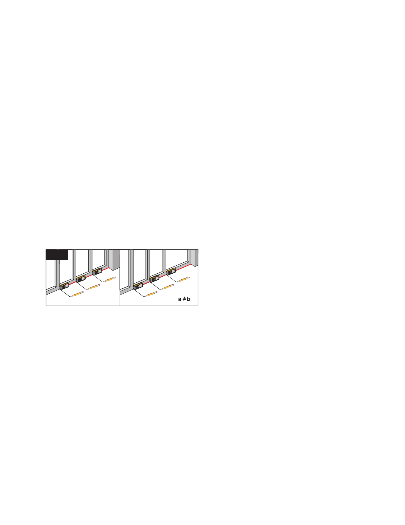
Stake Out Measurement (419D/424D)
A specific distance can be set in the Meter and used to
mark off defined measured lengths. An example of this
application is in the construction of wooden frames. See
Figure 14 for more information.
Note
For best results, it is recommended to use the
end reference point for a stake out
measurement. See page 16 for more
information.
1
2
3
a
b
b
0.625 m
0.625 m
1.012 m
1
2
3
a
b
b
a = b
0.625 m
0.625 m
0.625 m
14
gwo11.eps
419D (1 Value)
To find stake out distances with 1 value:
1. Push
4x. shows on the display.
2. Push and to increase and decrease the
value that shows in the summary line.
Note
Hold the buttons down to increase the rate of
change for the values.
3. Push
to accept the value.
The display shows the stake out distance in the
summary line between the stake out point and the
Meter (rear reference).
4. Move the Meter slowly along the stake out line and
the distance decreases on the display.
The arrows in the display indicate in which direction
the Meter needs to be moved in order to achieve the
defined distance.
Note
It the beeper feature is on, the Meter starts to
beep at a distance of 0.1 m (4 in) from the next
stake out point. As the Meter moves near to the
stake out point, the beep changes and the
arrows do not show on the display.
5. Push
to stop the stake out function.
1.888.610.7664 sales@GlobalTestSupply.com
Fluke-Direct.com

414D/419D/424D
Users Manual
24
424D (2 Values)
You can enter two different distances (a and b) into the
Meter and use them to mark off measured lengths, for
example, in the construction of wooden frames.
To find stake out distances with 2 values:
1. Push
4x. r shows in the display.
2. Push and to increase and decrease the
values that shows on the display.
The value (a), and the intermediate line that
corresponds, blink on the display.
3. Push
and to adjust the (a) value.
Note
Hold the buttons down to increase the rate of
change for the values.
4. Push
to accept the (a) value.
5. Push
and to adjust the (b) value.
6. Push to accept the (b) value.
The display shows the stake out distance in the
summary line between the stake out point (a and
then b) and the Meter (rear reference).
7. Move the Meter slowly along the stake out line the
displayed distance decreases.
The arrows in the display q indicate in which
direction the Meter needs to be moved in order to
achieve the defined distance (either a, or b).
Note
It the beeper feature is on, the Meter starts to
beep at a distance of 0.1 m (4 in) from the next
stake out point. As the Meter moves near to the
stake out point, the beep changes and the
arrows do not show on the display.
8. Push
to stop the stake out function.
1.888.610.7664 sales@GlobalTestSupply.com
Fluke-Direct.com
Laser Distance Meter
Measurements
25
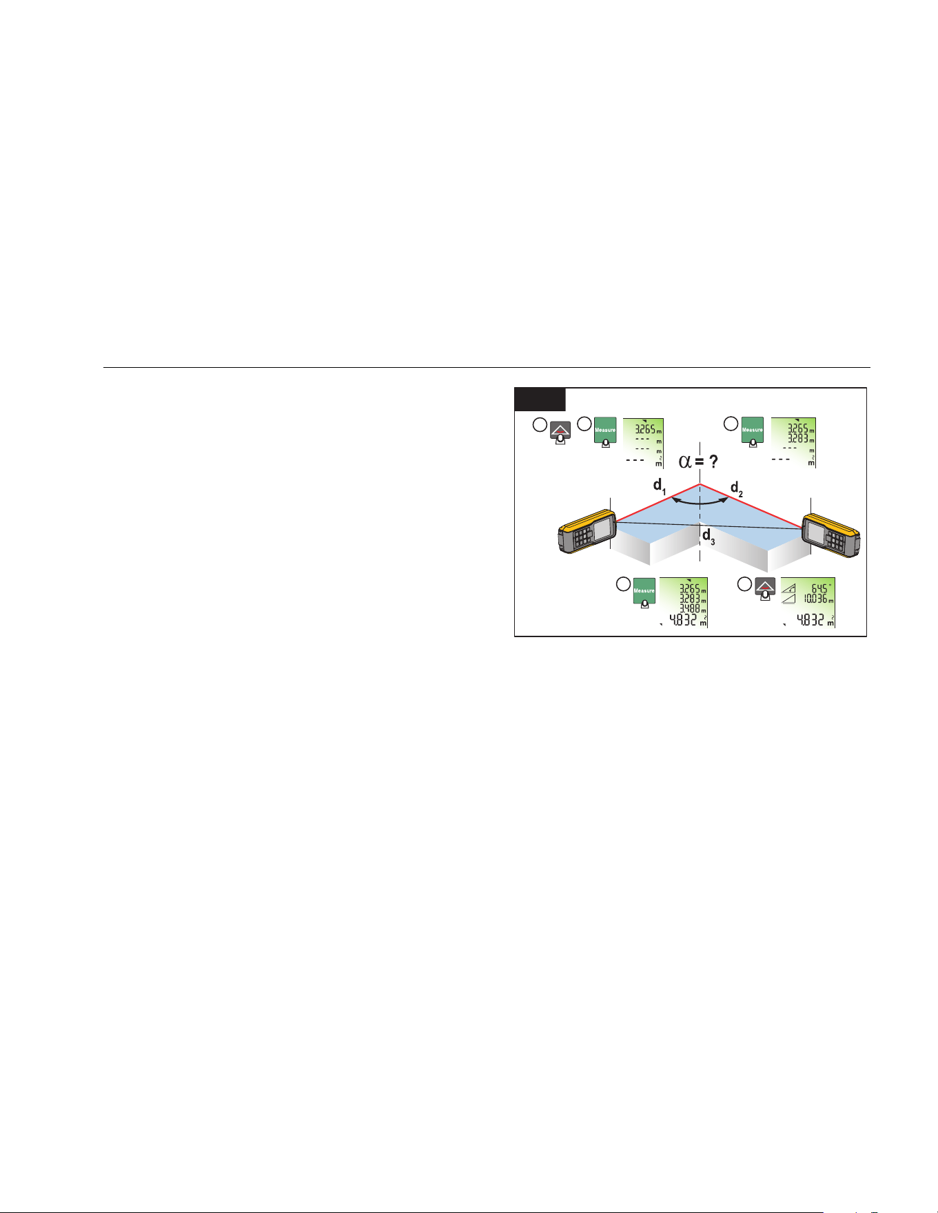
Corner Angle Measurement (424D only)
The Meter calculates the angles in a triangle with
measurements from the three sides. As an example, use
this function with a right-angle room corner. See
Figure 15 for more information.
To make corner angle measurements:
1. Push
1x. (room corner) shows in the display.
2. Put marks for the reference points to the right and left
(d1/d2) of the angle for measurement.
3. Push to make a measurement of the first side of
the triangle (d1 or d2).
4. Push
to make a measurement of the second
side of the triangle (d1 or d2).
5. Push
to make a measurement of the third side of
the triangle (d3).
6. The result shows in the summary line as the room
triangle area.
15
1
2
3
4 5
2 Sec.
gwo12.eps
7. Push for 2 seconds to get the second results as
the angle between d1 and d2, the triangle
circumference, and the area.
1.888.610.7664 sales@GlobalTestSupply.com
Fluke-Direct.com

414D/419D/424D
Users Manual
26
Indirect Measurement
The Meter can calculate distances with Pythagoras’
theorem. With this function, you can find a distance with
two auxiliary measurements, such as building height or
width measurements. It is helpful to use a tripod for a
height measurement that uses two or three
measurements.
Note
Make sure that you use the correct sequence of
measurement:
• All target points must be in a horizontal or
vertical plane.
• For the best results, turn the Meter about a
set point. An example of this is with the
endpiece fully open and the Meter on a wall.
• Make sure that the first measurement and
the measurement distance are at 90 °
angles.
• The minimum/maximum tracking is very
helpful for 90 ° angle measurements. See
page 17 for more information.
414D
To find a vertical distance with two measurements
(Pythagoras 1):
1. Push
3x. shows on the display.
2. Point the laser at the first target (1). See Figure 16.
3. Push
for the first distance (diagonal)
measurement.
4. Point the laser at the second target (2).
16
1
2
gwo13.eps
5. Make sure that the Meter is perpendicular to the wall.
6. Push for the second distance measurement.
The Meter shows the height in the summary line. The
distance of the second measurement shows in the
secondary line.
1.888.610.7664 sales@GlobalTestSupply.com
Fluke-Direct.com
Laser Distance Meter
Measurements
27
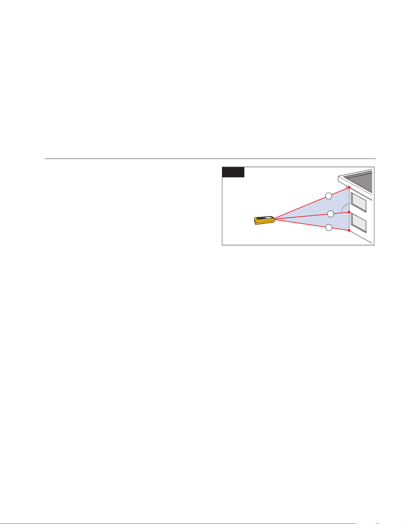
To find a total distance with three measurements
(Pythagoras 2):
1. Push
4x. shows on the display.
2. Point the laser at the first target (1). See Figure 17.
3. Push
for the first distance (diagonal)
measurement.
4. Point the laser at the second target (2).
5. Make sure that the Meter is perpendicular to the wall.
6. Push for the second distance.
7. Point the laser at the third (3) target.
8. Push
for the third distance measurement.
The Meter shows the height in the summary line. The
distance is the total vertical height from the first to
last targets. The third measurement shows in the
secondary line.
17
1
2
3
gwo14.eps
As an option, use the tracking mode on one or more
targets. To use tracking mode:
1. Push and hold
for 2 seconds to start tracking
mode.
2. Move the laser side to side and up and down on the
ideal horizontal target point.
3. Push
to stop the tracking mode.
1.888.610.7664 sales@GlobalTestSupply.com
Fluke-Direct.com
414D/419D/424D
Users Manual
28
419D/424D
To find a distance with two measurements
(Pythagoras 1):
1. Push
1x. shows on the display.
2. Point the laser at the top point (1). See Figure 16.
3. Push
.
4. Point the laser at the second target (2).
5. Make sure that the Meter is perpendicular to the wall.
6. Push
for the second distance measurement.
The Meter shows the height in the summary line. The
distance of the second measurement shows in the
secondary line.
To find a total distance with three measurements
(Pythagoras 2):
1. Push
2x. shows on the display.
2. Point the laser at the first target. See Figure 17.
3. Push
for the first distance (diagonal)
measurement.
4. Point the laser at the second target (2).
5. Make sure that the Meter is perpendicular to the wall.
6. Push
for the second distance.
7. Point the laser at the third (3) target.
8. Push
for the third distance measurement.
The Meter shows the result in the summary line. The
measured distance to the subsequent measurement
shows in the second line.
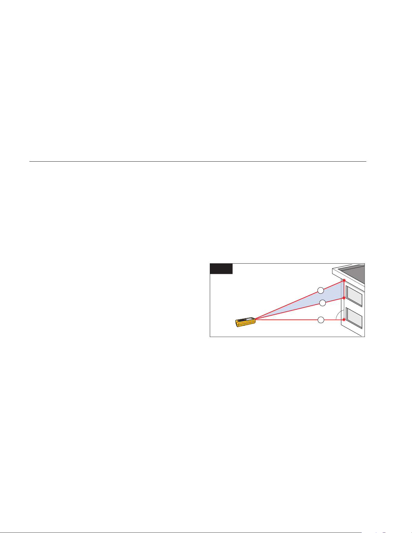
To find a partial distance, see Figure 18, with three
measurements (Pythagoras 3):
1. Push
3x. The laser turns on and shows on the
display.
2. Point at the top target (1).
18
1
2
3
gwo15.eps
3. Push . The Meter stores this measurement value.
4. Point the laser at the second diagonal target (2).
5. Push
for the second distance measurement.
1.888.610.7664 sales@GlobalTestSupply.com
Fluke-Direct.com

Laser Distance Meter
Memory (419D/424D)
29
6. Make sure that the Meter is perpendicular to the wall.
7. Push to trigger the bottom target (3)
measurement.
The result is the partial vertical distance between
target 1 and target 2. The third measurement shows
in the secondary line.
As an option, use the tracking mode on one or more
targets. To use tracking mode:
1. Push and hold
for 2 seconds to start tracking
mode.
2. Move the laser side to side and up and down on the
ideal horizontal target point.
3. Push
to stop the tracking mode.
Memory (419D/424D)
You can recall a previous measurement from memory, for
example, the height of a room. The Meter stores a
maximum of 20 displays.
To recall:
1. Push 1x.
2. Push and to move through the stored
displays.
and the memory ID show on the display.
3. Push for 2 seconds to use the value shown in
the Summary line for further calculations.
To delete:
1. Push
and at the same time.
The Meter deletes all the stored values in memory.
Maintenance
Maintenance and calibration is not necessary for the
Meter. To keep the Meter in good condition:
• Remove dirt with a moist, soft cloth.
• Do not put in water.
• Do not use aggressive detergents or solutions.
Disable the Meter
If damaged, do not use and disable the Meter. To disable,
remove the batteries. See page 6 for more information.
1.888.610.7664 sales@GlobalTestSupply.com
Fluke-Direct.com

414D/419D/424D
Users Manual
30
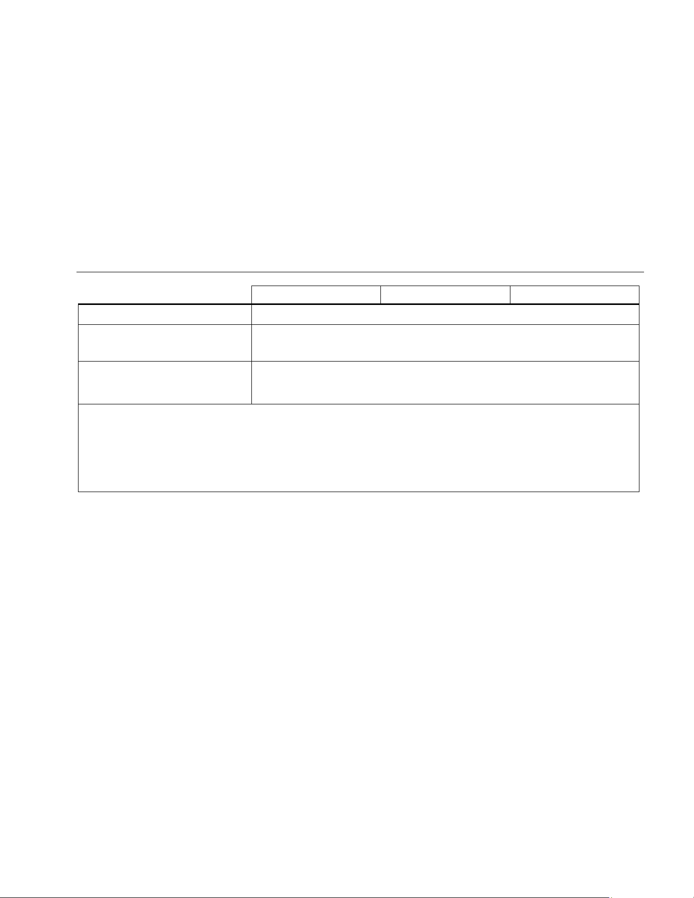
Message codes
Table 5 is a list of all message codes that show on the display with InFo or Error.
Table 5. Message Codes
Code Cause Remedy
156
Transverse tilt greater than 10 ° Hold the Meter without a transverse tilt.
162
Calibration mistake Make sure that the device is on a horizontal and flat surface. Do the
calibration procedure again. If the code continues, contact Fluke.
204
Calculation error Do the measurement again.
252
Temperature too high Let the Meter cool down.
253
Temperature too low Let the Meter warm up.
255
Received signal too low,
measurement time too long
Change target surface (for example, white paper).
256
Received signal too high Change target surface (for example, white paper)
257
Too much background light Darken target surface.
258
Measurement outside of
measurement range
Correct the range.
260
Laser beam interrupted Do the measurement again.
Error Hardware error Turn on and turn off the device 2 to 3 times. If the symbol stays on the
display, then your Meter is defective, contact Fluke.
1.888.610.7664 sales@GlobalTestSupply.com
Fluke-Direct.com
Laser Distance Meter
Specifications
31
Specifications
414D 419
D 424D
Distance Measurement
Typical Measurement Tolerance
[1]
± 2.0 mm (± 0.08 in)
[3]
± 1.0 mm (± 0.04 in)
[3]
Maximum Measurement Tolerance
[2]
± 3.0 mm (± 0.12 in)
[3]
± 2.0 mm (± 0.08 in)
[3]
Range at target plate 50 m / 165 ft 80 m / 260 ft 100 m / 330 ft
Typical Range
[1]
40 m / 130 ft 80 m / 260 ft
Range at unfavorable condition
[4]
35 m / 115 ft 60 m / 200 ft
Smallest unit displayed 1 mm / 1/16 in 1 mm / 1/32 in
∅ laser point at distances
6 mm @ 10 m / 30 mm @ 50 m / 60 mm @ 100 m
0.24 in @ 33 ft / 1.2 in @ 164 ft / 2.4 in @ 328 ft
Tilt measurement
Measurement tolerance to laser beam
[5]
no no ± 0.2 °
Measurement tolerance to case
[5]
no no ± 0.2 °
Range no no 360 °
Compass accuracy no no 8 points (± 22.5 °)
[6]
1.888.610.7664 sales@GlobalTestSupply.com
Fluke-Direct.com
414D/419D/424D
Users Manual
32
414D 419D 424D
General
Laser class 2
Laser type 635 nm, <1 mW
Protection class IP40 IP54
Automatic laser off 90 seconds
Automatic power off 180 seconds
Battery life (2 x AAA)
1.5 V NEDA 24A/IEC LR03
up to 3,000 measurements up to 5,000 measurements
Dimensions (H x W x L)
11.6 cm x 5.3 cm x 3.3 cm
(4.6 in x 2.1 in x 1.3 in)
12.7 x 5.6 x 3.3 cm
(5.0 in x 2.2 in x 1.3 in)
Weight (with batteries) 113 g (4 oz) 153 g (5 oz) 158 g (6 oz)
Temperature range:
Storage -25 °C to +70 °C -25 °C to +70 °C
(-13 °F to +158 °F) (-13 °F to +158 °F)
Operation 0 °C to +40 °C -10 °C to +50 °C
(32 °F to +104 °F) (14 °F to +122 °F)
Calibration cycle Not applicable Not applicable Tilt and Compass
Maximum altitude 3500 m
1.888.610.7664 sales@GlobalTestSupply.com
Fluke-Direct.com
Laser Distance Meter
Specifications
33
414D 419D 424D
Maximum relative humidity 85 % at 20 °F to 120 °F (-7 °C to 50 °C)
Safety IEC/EN 61010-1:2001
IEC/EN 60825-1:2007 (Class 2)
EMC
EN 55022:2010
EN 61000-4-3:2010
EN 61000-4-8:2010
[1] Applies for 100 % target reflectivity (white painted wall), low background illumination, 25 °C.
[2] Applies for 10 to 500 % target reflectivity, high background illumination, -10
°C to +50 °C.
[3] Tolerances apply from 0.05 m to 10 m with a confidence level of 95 %. The maximum tolerance may deteriorate to 0.15 mm/m between 10 m to 30 m
and to 0.2 mm/m for distances above 30 m.
[4] Applies for 100 % target reflectivity, background illumination ~ 30,000 lux.
[5] After user calibration. Additional angle related deviation of ±0.01
° per degree up to ±45 ° in each quadrant. Applies at room temperature. For the whole
operating temperature range the maximum deviation increases by ±0.1
°.
[6] After calibration. Do not use the compass for navigation.
1.888.610.7664 sales@GlobalTestSupply.com
Fluke-Direct.com