
XGS2220 Series User’s Guide
2
IMPORTANT!
READ CAREFULLY BEFORE USE.
KEEP THIS GUIDE FOR FUTURE REFERENCE.
This is a User’s Guide for a series of products. Not all products support all firmware features. Screenshots
and graphics in this book may differ slightly from your products due to differences in your product
firmware or your computer operating system. Every effort has been made to ensure that the information
in this manual is accurate.
Note: The version number on the cover page refers to the Switch’es latest firmware version to
which this User’s Guide applies.
Related Documentation
•Quick Start Guide
The Quick Start Guide shows how to connect the Switch.
•CLI Reference Guide
This guide explains how to use the Command-Line Interface (CLI) to configure the Switch.
Note: It is recommended you use the Web Configurator to configure the Switch.
• Web Configurator Online Help
Click the help link for a description of the fields in the Switch menus.
• Nebula Control Center (NCC) User’s Guide
Go to nebula.zyxel.com or support.zyxel.com to get this User’s Guide on how to configure the Switch
using Nebula.
•More Information
Go to support.zyxel.com to find other information on the Switch.
XGS2220 Series User’s Guide
3
Document Conventions
Warnings and Notes
These are how warnings and notes are shown in this guide.
Warnings tell you about things that could harm you or your device.
Note: Notes tell you other important information (for example, other things you may need to
configure or helpful tips) or recommendations.
Syntax Conventions
• All models may be referred to as the “Switch” in this guide.
• Product labels, screen names, field labels and field choices are all in bold font.
• A right angle bracket ( > ) within a screen name denotes a mouse click. For example, SYSTEM > IP
Setup > Network Proxy Configuration means you first click SYSTEM in the navigation panel, then the IP
Setup sub menu, then Network Proxy Configuration to get to that screen.
Icons Used in Figures
Figures in this user guide may use the following generic icons. The Switch icon is not an exact
representation of your device.
Switch Generic Router Wireless Router / Access Point
Generic Switch Smart TV Desktop
Laptop IP Camera Printer
Server

Contents Overview
XGS2220 Series User’s Guide
4
Contents Overview
User’s Guide ......................................................................................................................................27
Getting to Know Your Switch .............................................................................................................. 28
Hardware Installation and Connection ............................................................................................. 41
Hardware Panels .................................................................................................................................. 45
Technical Reference ........................................................................................................................57
Web Configurator ................................................................................................................................. 58
Initial Setup Example .......................................................................................................................... 101
Tutorials ................................................................................................................................................ 106
DASHBOARD ........................................................................................................................................ 117
MONITOR ............................................................................................................................................. 123
ARP Table ............................................................................................................................................ 124
IP Table ................................................................................................................................................. 126
IPv6 Neighbor Table ........................................................................................................................... 128
MAC Table ........................................................................................................................................... 130
Neighbor ............................................................................................................................................. 133
Path MTU Table ................................................................................................................................... 139
Port Status ............................................................................................................................................ 140
Routing Table ...................................................................................................................................... 149
System Information ............................................................................................................................. 151
System Log .......................................................................................................................................... 156
SYSTEM ................................................................................................................................................. 157
Cloud Management .......................................................................................................................... 158
General Setup ..................................................................................................................................... 160
Interface Setup ................................................................................................................................... 164
IP Setup ................................................................................................................................................ 166
IPv6 ....................................................................................................................................................... 173
Logins ................................................................................................................................................... 190
SNMP .................................................................................................................................................... 192
Stacking ............................................................................................................................................... 203
Switch Setup ........................................................................................................................................ 211
Syslog Setup ........................................................................................................................................ 214
Time Range ......................................................................................................................................... 217
PORT ..................................................................................................................................................... 220
Auto PD Recovery .............................................................................................................................. 221
Flex Link ................................................................................................................................................ 226
Green Ethernet ................................................................................................................................... 230
Link Aggregation ................................................................................................................................ 234

Contents Overview
XGS2220 Series User’s Guide
5
Link Layer Discovery Protocol (LLDP) ................................................................................................ 245
OAM ..................................................................................................................................................... 272
PoE Setup ............................................................................................................................................. 282
Port Setup ............................................................................................................................................ 291
ZULD ...................................................................................................................................................... 294
SWITCHING .......................................................................................................................................... 300
Layer 2 Protocol Tunneling ................................................................................................................ 301
Loop Guard ......................................................................................................................................... 306
MAC Pinning ....................................................................................................................................... 310
Mirroring ............................................................................................................................................... 313
Multicast .............................................................................................................................................. 315
Static Multicast Forwarding ............................................................................................................... 346
PPPoE ................................................................................................................................................... 351
Differentiated Services ....................................................................................................................... 360
Queuing Method ................................................................................................................................ 365
Priority Queue ..................................................................................................................................... 369
Bandwidth Control ............................................................................................................................. 371
sFlow ..................................................................................................................................................... 374
Spanning Tree Protocol ...................................................................................................................... 378
Static MAC Filtering ............................................................................................................................ 410
Static MAC Forwarding ...................................................................................................................... 412
VLAN .................................................................................................................................................... 415
VLAN Isolation ..................................................................................................................................... 442
VLAN Mapping ................................................................................................................................... 445
VLAN Stacking .................................................................................................................................... 450
NETWORKING ...................................................................................................................................... 459
ARP Setup ............................................................................................................................................ 460
DHCP .................................................................................................................................................... 466
Static Route ......................................................................................................................................... 480
SECURITY .............................................................................................................................................. 484
AAA ...................................................................................................................................................... 485
Access Control .................................................................................................................................... 499
Classifier ............................................................................................................................................... 509
Policy Rule ........................................................................................................................................... 518
Anti-Arpscan ....................................................................................................................................... 524
BPDU Guard ........................................................................................................................................ 531
Storm Control ...................................................................................................................................... 535
Error-Disable ........................................................................................................................................ 538
IP Source Guard .................................................................................................................................. 546
DHCP Snooping .................................................................................................................................. 551
ARP Inspection .................................................................................................................................... 563
Port Authentication ............................................................................................................................ 584
Port Security ......................................................................................................................................... 599

Contents Overview
XGS2220 Series User’s Guide
6
MAINTENANCE .................................................................................................................................... 603
Networked AV Mode ......................................................................................................................... 629
Troubleshooting and Appendices .................................................................................................688
Troubleshooting .................................................................................................................................. 689

Table of Contents
XGS2220 Series User’s Guide
7
Table of Contents
Document Conventions ......................................................................................................................3
Contents Overview..............................................................................................................................4
Table of Contents.................................................................................................................................7
Part I: User’s Guide..........................................................................................27
Chapter 1
Getting to Know Your Switch ............................................................................................................28
1.1 Introduction ..................................................................................................................................... 28
1.1.1 Multi-Gigabit .......................................................................................................................... 29
1.1.2 Stacking Mode ...................................................................................................................... 30
1.1.3 Management Modes ........................................................................................................... 31
1.1.4 Mode Changing ................................................................................................................... 32
1.1.5 ZON Utility ............................................................................................................................... 34
1.1.6 Web Configurator Networked AV Mode ........................................................................... 34
1.1.7 PoE .......................................................................................................................................... 35
1.2 Example Applications .................................................................................................................... 36
1.2.1 PoE Example Application ..................................................................................................... 36
1.2.2 Backbone Example Application ......................................................................................... 36
1.2.3 Bridging or Fiber Optic Uplink Example Application ......................................................... 37
1.2.4 High Performance Switching Example ............................................................................... 37
1.2.5 IEEE 802.1Q VLAN Application Examples ........................................................................... 38
1.2.6 IPv6 Support ........................................................................................................................... 39
1.3 Ways to Manage the Switch ......................................................................................................... 39
1.4 Good Habits for Managing the Switch ........................................................................................40
Chapter 2
Hardware Installation and Connection ...........................................................................................41
2.1 Installation Scenarios ...................................................................................................................... 41
2.2 Safety Precautions .......................................................................................................................... 41
2.3 Freestanding Installation Procedure ............................................................................................ 41
2.4 Mounting the Switch on a Rack ................................................................................................... 42
2.4.1 Installation Requirements ..................................................................................................... 42
2.4.2 Precautions ............................................................................................................................ 42
2.4.3 Attaching the Mounting Brackets to the Switch ............................................................... 43
2.4.4 Mounting the Switch on a Rack .......................................................................................... 43

Table of Contents
XGS2220 Series User’s Guide
8
Chapter 3
Hardware Panels................................................................................................................................45
3.1 Front Panel Connections ............................................................................................................... 45
3.1.1 Multi-Gigabit Ethernet Ports ................................................................................................. 46
3.1.2 SFP/SFP+ Slots ......................................................................................................................... 47
3.1.3 Console Port .......................................................................................................................... 49
3.2 Rear Panel ....................................................................................................................................... 49
3.2.1 Grounding .............................................................................................................................. 50
3.2.2 AC Power Connection ......................................................................................................... 52
3.3 LEDs .................................................................................................................................................. 54
Part II: Technical Reference...........................................................................57
Chapter 4
Web Configurator...............................................................................................................................58
4.1 Overview ......................................................................................................................................... 58
4.2 System Login .................................................................................................................................... 58
4.3 Zyxel One Network (ZON) Utility .................................................................................................... 63
4.3.1 Requirements ......................................................................................................................... 63
4.3.2 Run the ZON Utility ................................................................................................................. 63
4.4 Networked AV Mode Wizard ........................................................................................................ 67
4.4.1 Basic Settings ......................................................................................................................... 67
4.4.2 Advanced Settings ............................................................................................................... 72
4.5 Wizard .............................................................................................................................................. 77
4.5.1 Basic ....................................................................................................................................... 78
4.5.2 Protection .............................................................................................................................. 83
4.5.3 VLAN ....................................................................................................................................... 85
4.5.4 QoS ......................................................................................................................................... 86
4.6 Web Configurator Layout .............................................................................................................. 87
4.6.1 Tables and Lists ...................................................................................................................... 95
4.6.2 Change Your Password ........................................................................................................ 97
4.7 Save Your Configuration ................................................................................................................ 97
4.8 Switch Lockout ................................................................................................................................ 97
4.9 Reset the Switch ............................................................................................................................. 98
4.9.1 Reboot the Switch ................................................................................................................ 98
4.9.2 Reload the Configuration File .............................................................................................. 98
4.10 Log Out of the Web Configurator .............................................................................................. 99
4.11 Help ................................................................................................................................................ 99
Chapter 5
Initial Setup Example.......................................................................................................................101

Table of Contents
XGS2220 Series User’s Guide
9
5.1 Overview ....................................................................................................................................... 101
5.1.1 Create a VLAN .................................................................................................................... 101
5.1.2 Set Port VID .......................................................................................................................... 102
5.1.3 Configure Switch Management IP Address ..................................................................... 103
Chapter 6
Tutorials.............................................................................................................................................106
6.1 Overview ....................................................................................................................................... 106
6.2 How to Use DHCPv4 Snooping on the Switch ........................................................................... 106
6.3 How to Use DHCPv4 Relay on the Switch .................................................................................. 110
6.3.1 DHCP Relay Tutorial Introduction ...................................................................................... 110
6.3.2 Create a VLAN .................................................................................................................... 110
6.3.3 Configure DHCPv4 Relay ...................................................................................................113
6.3.4 Troubleshooting ................................................................................................................... 114
6.4 How to Use Auto Configuration through a DHCP Server on the Switch ................................ 114
Chapter 7
DASHBOARD .....................................................................................................................................117
7.1 New User Interface ....................................................................................................................... 117
7.2 DASHBOARD .................................................................................................................................. 117
7.2.1 Port Status ............................................................................................................................ 121
7.2.2 Quick Links to Use ................................................................................................................ 122
Chapter 8
MONITOR...........................................................................................................................................123
Chapter 9
ARP Table..........................................................................................................................................124
9.1 ARP Table Overview ..................................................................................................................... 124
9.1.1 What You Can Do ............................................................................................................... 124
9.1.2 What You Need to Know ................................................................................................... 124
9.2 Viewing the ARP Table ................................................................................................................. 124
Chapter 10
IP Table..............................................................................................................................................126
10.1 IP Table Overview ....................................................................................................................... 126
10.2 Viewing the IP Table ................................................................................................................... 127
Chapter 11
IPv6 Neighbor Table.........................................................................................................................128
11.1 IPv6 Neighbor Table Overview .................................................................................................. 128
11.2 Viewing the IPv6 Neighbor Table ............................................................................................. 128

Table of Contents
XGS2220 Series User’s Guide
10
Chapter 12
MAC Table........................................................................................................................................130
12.1 MAC Table Overview ................................................................................................................. 130
12.1.1 What You Can Do ............................................................................................................. 130
12.1.2 What You Need to Know ................................................................................................. 130
12.2 Viewing the MAC Table ............................................................................................................. 131
Chapter 13
Neighbor ..........................................................................................................................................133
13.1 Neighbor Overview .................................................................................................................... 133
13.1.1 What You Can Do ............................................................................................................. 133
13.2 Neighbor ...................................................................................................................................... 133
13.2.1 Neighbor Details ................................................................................................................ 135
Chapter 14
Path MTU Table.................................................................................................................................139
14.1 Path MTU Overview .................................................................................................................... 139
14.2 Viewing the Path MTU Table ..................................................................................................... 139
Chapter 15
Port Status .........................................................................................................................................140
15.0.1 What You Can Do ............................................................................................................. 140
15.1 Port Status .................................................................................................................................... 140
15.1.1 Port Details ......................................................................................................................... 142
15.2 DDMI ............................................................................................................................................ 144
15.2.1 DDMI Details ...................................................................................................................... 145
15.3 Port Utilization .............................................................................................................................. 147
Chapter 16
Routing Table....................................................................................................................................149
16.1 Routing Table Overview ............................................................................................................ 149
16.1.1 What You Can Do ............................................................................................................. 149
16.2 IPv4 Routing Table ...................................................................................................................... 149
16.3 IPv6 Routing Table ...................................................................................................................... 150
Chapter 17
System Information..........................................................................................................................151
17.0.1 What You Can Do ............................................................................................................. 151
17.1 System Information ..................................................................................................................... 151
17.2 Hardware Monitor (Stacking Mode) ........................................................................................ 153
Chapter 18
System Log........................................................................................................................................156

Table of Contents
XGS2220 Series User’s Guide
11
18.1 System Log Overview ................................................................................................................. 156
18.2 System Log .................................................................................................................................. 156
Chapter 19
SYSTEM ..............................................................................................................................................157
Chapter 20
Cloud Management........................................................................................................................158
20.1 Cloud Management Overview ................................................................................................ 158
20.2 Nebula Center Control Discovery ............................................................................................ 158
Chapter 21
General Setup..................................................................................................................................160
21.1 General Setup ............................................................................................................................. 160
21.2 Hardware Monitor Setup ........................................................................................................... 162
Chapter 22
Interface Setup.................................................................................................................................164
22.1 Interface Setup Overview ......................................................................................................... 164
22.2 Interface Setup ........................................................................................................................... 164
22.2.1 Add/Edit Interfaces ........................................................................................................... 165
Chapter 23
IP Setup .............................................................................................................................................166
23.1 IP Setup Overview ...................................................................................................................... 166
23.1.1 What You Can Do ............................................................................................................. 166
23.1.2 IP Interfaces ....................................................................................................................... 166
23.2 IP Status ........................................................................................................................................ 167
23.2.1 IP Status Details .................................................................................................................. 167
23.3 IP Setup ........................................................................................................................................ 169
23.3.1 Add/Edit IP Interfaces ....................................................................................................... 170
23.4 Network Proxy Configuration .................................................................................................... 171
Chapter 24
IPv6....................................................................................................................................................173
24.1 IPv6 Overview ............................................................................................................................. 173
24.1.1 What You Can Do ............................................................................................................. 173
24.2 IPv6 Status .................................................................................................................................... 173
24.2.1 IPv6 Interface Status Details ............................................................................................. 174
24.3 IPv6 Global Setup ....................................................................................................................... 176
24.4 IPv6 Interface Setup ................................................................................................................... 177
24.4.1 Edit an IPv6 Interface ........................................................................................................ 178
24.5 IPv6 Link-Local Address Setup ................................................................................................... 178
24.5.1 Edit an IPv6 Link-Local Address ........................................................................................ 179

Table of Contents
XGS2220 Series User’s Guide
12
24.6 IPv6 Global Address Setup ........................................................................................................ 180
24.6.1 Add/Edit an IPv6 Global Address .................................................................................... 180
24.7 IPv6 Neighbor Discovery Setup ................................................................................................. 181
24.7.1 Edit an IPv6 Neighbor Discovery ..................................................................................... 182
24.8 IPv6 Router Discovery Setup ...................................................................................................... 183
24.8.1 Edit IPv6 Router Discovery ................................................................................................ 183
24.9 IPv6 Prefix Setup .......................................................................................................................... 184
24.9.1 Add/Edit IPv6 Prefix ........................................................................................................... 185
24.10 IPv6 Neighbor Setup ................................................................................................................. 186
24.10.1 Add/Edit IPv6 Neighbor .................................................................................................. 187
24.11 DHCPv6 Client Setup ................................................................................................................ 187
24.11.1 Edit DHCPv6 Client .......................................................................................................... 188
Chapter 25
Logins................................................................................................................................................190
25.1 Set Up Login Accounts ............................................................................................................... 190
Chapter 26
SNMP .................................................................................................................................................192
26.1 SNMP Overview .......................................................................................................................... 192
26.1.1 What You Can Do ............................................................................................................. 192
26.2 Configure SNMP .......................................................................................................................... 192
26.3 Configure SNMP User ................................................................................................................. 194
26.3.1 Add/Edit SNMP User .......................................................................................................... 194
26.4 SNMP Trap Group ....................................................................................................................... 196
26.5 Enable or Disable Sending of SNMP Traps on a Port .............................................................. 197
26.6 Technical Reference .................................................................................................................. 198
26.6.1 About SNMP ....................................................................................................................... 198
Chapter 27
Stacking............................................................................................................................................203
27.1 Stacking Overview ..................................................................................................................... 203
27.1.1 What You Can Do ............................................................................................................. 203
27.1.2 What you need to know .................................................................................................. 203
27.2 Stacking Status ............................................................................................................................ 204
27.2.1 Stacking Slot Details .......................................................................................................... 205
27.3 Stacking Setup ............................................................................................................................ 207
27.4 Stacking Port Setup .................................................................................................................... 209
Chapter 28
Switch Setup.....................................................................................................................................211
28.1 Switch Setup Overview .............................................................................................................. 211
28.1.1 Introduction to VLANs ....................................................................................................... 211

Table of Contents
XGS2220 Series User’s Guide
13
28.2 Switch Setup ................................................................................................................................ 211
Chapter 29
Syslog Setup .....................................................................................................................................214
29.1 Syslog Overview .......................................................................................................................... 214
29.1.1 What You Can Do ............................................................................................................. 214
29.2 Syslog Setup ................................................................................................................................ 214
29.2.1 Add/Edit a Syslog Server .................................................................................................. 216
Chapter 30
Time Range.......................................................................................................................................217
30.1 Time Range Overview ................................................................................................................ 217
30.1.1 What You Can Do ............................................................................................................. 217
30.2 Configuring Time Range ............................................................................................................ 217
30.2.1 Add/Edit Time Range ....................................................................................................... 218
Chapter 31
PORT ..................................................................................................................................................220
Chapter 32
Auto PD Recovery............................................................................................................................221
32.1 Auto PD Recovery (for PoE models only) Overview ............................................................... 221
32.1.1 What You Can Do ............................................................................................................. 221
32.2 Auto PD Recovery ...................................................................................................................... 221
32.2.1 Activate the Automatic PD Recovery ............................................................................ 223
Chapter 33
Flex Link ............................................................................................................................................226
33.1 Flex Link Overview ...................................................................................................................... 226
33.1.1 What You Can Do ............................................................................................................. 226
33.2 Flex Link Status ............................................................................................................................. 226
33.3 Flex Link Setup ............................................................................................................................. 227
33.3.1 Add/Edit Flex Link .............................................................................................................. 228
Chapter 34
Green Ethernet.................................................................................................................................230
34.1 Green Ethernet Overview .......................................................................................................... 230
34.2 Configuring Green Ethernet ...................................................................................................... 230
Chapter 35
Link Aggregation .............................................................................................................................234
35.1 Link Aggregation Overview ....................................................................................................... 234
35.1.1 What You Can Do ............................................................................................................. 234
35.1.2 What You Need to Know ................................................................................................. 234

Table of Contents
XGS2220 Series User’s Guide
14
35.2 Link Aggregation Status ............................................................................................................. 236
35.3 Link Aggregation Setting ........................................................................................................... 237
35.4 Link Aggregation Control Protocol ........................................................................................... 240
35.5 Technical Reference .................................................................................................................. 243
35.5.1 Static Trunking Example ................................................................................................... 243
Chapter 36
Link Layer Discovery Protocol (LLDP) .............................................................................................245
36.1 LLDP Overview ............................................................................................................................ 245
36.2 LLDP-MED Overview ................................................................................................................... 246
36.2.1 What You Can Do – LLDP ................................................................................................. 247
36.2.2 What You Can Do – LLDP MED ........................................................................................ 247
36.3 LLDP Local Status ........................................................................................................................ 247
36.3.1 LLDP Local Port Status Details ..........................................................................................249
36.4 LLDP Remote Status .................................................................................................................... 252
36.4.1 LLDP Remote Port Status Details ...................................................................................... 253
36.5 LLDP Setup ................................................................................................................................... 258
36.6 Basic TLV Setting ......................................................................................................................... 261
36.7 Org-specific TLV Setting ............................................................................................................. 263
36.8 LLDP-MED Setup .......................................................................................................................... 264
36.9 LLDP-MED Network Policy .......................................................................................................... 266
36.9.1 Add/Edit LLDP-MED Network Policy ................................................................................ 267
36.10 LLDP-MED Location .................................................................................................................. 268
36.10.1 Add/Edit LLDP-MED Location ........................................................................................ 268
Chapter 37
OAM..................................................................................................................................................272
37.1 OAM Overview ........................................................................................................................... 272
37.1.1 What You Can Do ............................................................................................................. 272
37.2 OAM Status .................................................................................................................................. 272
37.2.1 OAM Details ....................................................................................................................... 274
37.3 OAM Setup .................................................................................................................................. 278
37.4 OAM Remote Loopback ........................................................................................................... 280
Chapter 38
PoE Setup..........................................................................................................................................282
38.1 PoE Status (for PoE models only) ............................................................................................... 282
38.2 PoE Setup ..................................................................................................................................... 285
38.3 PoE Time Range Setup ............................................................................................................... 288
38.3.1 Add/Edit PoE Time Range ................................................................................................ 289
Chapter 39
Port Setup..........................................................................................................................................291

Table of Contents
XGS2220 Series User’s Guide
15
39.1 Port Setup .................................................................................................................................... 291
Chapter 40
ZULD...................................................................................................................................................294
40.1 ZULD Overview ............................................................................................................................ 294
40.1.1 What You Can Do ............................................................................................................. 294
40.1.2 What You Need to Know ................................................................................................. 294
40.2 ZULD Status .................................................................................................................................. 295
40.3 ZULD Setup ................................................................................................................................... 297
Chapter 41
SWITCHING........................................................................................................................................300
Chapter 42
Layer 2 Protocol Tunneling..............................................................................................................301
42.1 Layer 2 Protocol Tunneling Overview .......................................................................................301
42.1.1 What You Can Do ............................................................................................................. 301
42.1.2 What You Need to Know ................................................................................................. 301
42.2 Configuring Layer 2 Protocol Tunneling ................................................................................... 302
Chapter 43
Loop Guard ......................................................................................................................................306
43.1 Loop Guard Overview ............................................................................................................... 306
43.1.1 What You Can Do ............................................................................................................. 306
43.1.2 What You Need to Know ................................................................................................. 306
43.2 Loop Guard Setup ...................................................................................................................... 308
Chapter 44
MAC Pinning.....................................................................................................................................310
44.1 MAC Pinning Overview .............................................................................................................. 310
44.2 MAC Pinning Configuration ...................................................................................................... 310
Chapter 45
Mirroring............................................................................................................................................313
45.1 Mirroring Overview ..................................................................................................................... 313
45.2 Local Port Mirroring ..................................................................................................................... 313
Chapter 46
Multicast............................................................................................................................................315
46.1 Multicast Overview ..................................................................................................................... 315
46.1.1 What You Can Do – IPv6 Multicast ................................................................................. 315
46.1.2 What You Can Do – MVR ................................................................................................. 316
46.1.3 What You Need to Know ................................................................................................. 316
46.2 IPv4 Multicast Status ................................................................................................................... 319

Table of Contents
XGS2220 Series User’s Guide
16
46.3 IGMP Snooping ........................................................................................................................... 320
46.4 IGMP Snooping VLAN ................................................................................................................ 324
46.4.1 Add/Edit IGMP Snooping VLANs ..................................................................................... 325
46.5 IGMP Filtering Profile ................................................................................................................... 326
46.5.1 Add IGMP Filtering Profile ................................................................................................. 327
46.5.2 Add IGMP Filtering Rule .................................................................................................... 327
46.6 IPv6 Multicast Status ................................................................................................................... 328
46.7 MLD Snooping-proxy .................................................................................................................. 329
46.8 MLD Snooping-proxy VLAN ....................................................................................................... 329
46.8.1 Add/Edit MLD Snooping-proxy VLAN ............................................................................. 330
46.9 MLD Snooping-proxy Port Role Setting ..................................................................................... 332
46.10 MLD Snooping-proxy Filtering .................................................................................................. 334
46.11 MLD Snooping-proxy Filtering Profile ...................................................................................... 336
46.11.1 Add MLD Snooping-proxy Filtering Profile .................................................................... 337
46.11.2 Add MLD Snooping-proxy Filtering Rule ....................................................................... 338
46.12 MVR Configuration ................................................................................................................... 338
46.12.1 Add/Edit MVR .................................................................................................................. 339
46.13 MVR Group Setup ..................................................................................................................... 341
46.13.1 Add/Edit MVR Group ...................................................................................................... 342
46.13.2 MVR Configuration Example ......................................................................................... 343
Chapter 47
Static Multicast Forwarding.............................................................................................................346
47.1 Static Multicast Forwarding Overview ..................................................................................... 346
47.1.1 What You Can Do ............................................................................................................. 346
47.1.2 What You Need To Know ................................................................................................. 346
47.2 Static Multicast Forwarding By MAC ........................................................................................347
47.2.1 Add/Edit Static Multicast Forwarding By MAC .............................................................. 348
47.3 Configure a Static Multicast IPv4 Address ............................................................................... 349
47.3.1 Add/Edit a Static Multicast Address By IP ...................................................................... 349
Chapter 48
PPPoE.................................................................................................................................................351
48.1 PPPoE Intermediate Agent Overview ...................................................................................... 351
48.1.1 What You Can Do ............................................................................................................. 351
48.1.2 What You Need to Know ................................................................................................. 351
48.2 PPPoE Intermediate Agent ........................................................................................................ 353
48.3 PPPoE IA Port ............................................................................................................................... 355
48.4 PPPoE IA Port VLAN .................................................................................................................... 356
48.5 PPPoE IA VLAN ............................................................................................................................ 358
Chapter 49
Differentiated Services ....................................................................................................................360

Table of Contents
XGS2220 Series User’s Guide
17
49.1 DiffServ Overview ....................................................................................................................... 360
49.1.1 What You Can Do ............................................................................................................. 360
49.1.2 What You Need to Know ................................................................................................. 360
49.2 Activating DiffServ ...................................................................................................................... 361
49.3 DSCP-to-IEEE 802.1p Priority Settings ......................................................................................... 363
49.3.1 Configuring DSCP Settings ...............................................................................................363
Chapter 50
Queuing Method..............................................................................................................................365
50.1 Queuing Method Overview ...................................................................................................... 365
50.1.1 What You Can Do ............................................................................................................. 365
50.1.2 What You Need to Know ................................................................................................. 365
50.2 Configuring Queuing ................................................................................................................. 366
Chapter 51
Priority Queue...................................................................................................................................369
51.1 Priority Queue Overview ............................................................................................................ 369
51.1.1 What You Can Do ............................................................................................................. 369
51.2 Assign Priority Queue .................................................................................................................. 369
Chapter 52
Bandwidth Control...........................................................................................................................371
52.1 Bandwidth Control Overview .................................................................................................... 371
52.1.1 What You Can Do ............................................................................................................. 371
52.1.2 CIR and PIR ........................................................................................................................ 371
52.2 Bandwidth Control Setup .......................................................................................................... 371
Chapter 53
sFlow..................................................................................................................................................374
53.1 sFlow Overview ........................................................................................................................... 374
53.2 sFlow Port Configuration ............................................................................................................ 374
53.3 sFlow Collector Configuration ................................................................................................... 376
53.3.1 Add/Edit sFlow Collector .................................................................................................. 377
Chapter 54
Spanning Tree Protocol ...................................................................................................................378
54.1 Spanning Tree Protocol Overview ............................................................................................ 378
54.1.1 What You Can Do ............................................................................................................. 378
54.1.2 What You Need to Know ................................................................................................. 378
54.2 Spanning Tree Protocol Status .................................................................................................. 381
54.3 Spanning Tree Setup .................................................................................................................. 382
54.4 Rapid Spanning Tree Protocol Status .......................................................................................385
54.5 Configure Rapid Spanning Tree Protocol ................................................................................ 387

Table of Contents
XGS2220 Series User’s Guide
18
54.6 Multiple Rapid Spanning Tree Protocol .................................................................................... 391
54.7 Configure Multiple Rapid Spanning Tree Protocol ................................................................. 393
54.8 Multiple Spanning Tree Protocol Status ....................................................................................397
54.9 Configure Multiple Spanning Tree Protocol ............................................................................ 401
54.9.1 Add/Edit Multiple Spanning Tree .................................................................................... 403
54.10 Multiple Spanning Tree Protocol Port Setup .......................................................................... 405
54.11 Technical Reference ................................................................................................................ 407
54.11.1 MSTP Network Example .................................................................................................. 407
54.11.2 MST Region ....................................................................................................................... 407
54.11.3 MST Instance .................................................................................................................... 408
54.11.4 Common and Internal Spanning Tree (CIST) ............................................................... 408
Chapter 55
Static MAC Filtering..........................................................................................................................410
55.1 Static MAC Filtering Overview .................................................................................................. 410
55.1.1 What You Can Do ............................................................................................................. 410
55.2 Configure a Static MAC Filtering Rule ...................................................................................... 410
55.2.1 Add/Edit a Static MAC Filtering Rule .............................................................................. 411
Chapter 56
Static MAC Forwarding....................................................................................................................412
56.1 Static MAC Forwarding Overview ............................................................................................412
56.1.1 What You Can Do ............................................................................................................. 412
56.2 Configure Static MAC Forwarding ...........................................................................................412
56.2.1 Add/Edit Static MAC Forwarding Rules .......................................................................... 413
Chapter 57
VLAN..................................................................................................................................................415
57.1 VLAN Overview ........................................................................................................................... 415
57.1.1 What You Can Do ............................................................................................................. 415
57.1.2 What You Need to Know ................................................................................................. 415
57.2 Introduction to IEEE 802.1Q Tagged VLANs ............................................................................. 416
57.3 VLAN Status ................................................................................................................................. 418
57.3.1 VLAN Details ...................................................................................................................... 419
57.4 Configure a Static VLAN ............................................................................................................ 421
57.4.1 Add/Edit a Static VLAN .................................................................................................... 421
57.5 VLAN Port Setup .......................................................................................................................... 423
57.6 Configure GVRP .......................................................................................................................... 425
57.7 Subnet Based VLAN ................................................................................................................... 427
57.8 Configuring Subnet Based VLAN .............................................................................................. 428
57.8.1 Add/Edit Subnet Based VLAN ......................................................................................... 429
57.9 Protocol Based VLAN ................................................................................................................. 430
57.10 Configuring Protocol Based VLAN ..........................................................................................430

Table of Contents
XGS2220 Series User’s Guide
19
57.10.1 Add/Edit a Protocol Based VLAN .................................................................................. 431
57.11 Voice VLAN ............................................................................................................................... 433
57.11.1 Add/Edit a Voice VLAN ..................................................................................................434
57.12 MAC Based VLAN ..................................................................................................................... 435
57.12.1 Add/Edit a MAC Based VLAN ....................................................................................... 436
57.13 Vendor ID Based VLAN ............................................................................................................ 437
57.13.1 Add/Edit a Vendor ID Based VLAN ............................................................................... 437
57.14 Port-Based VLAN Setup ............................................................................................................ 438
57.15 Configure a Port-Based VLAN ................................................................................................. 439
Chapter 58
VLAN Isolation..................................................................................................................................442
58.1 VLAN Isolation Overview ............................................................................................................ 442
58.2 Configuring VLAN Isolation ........................................................................................................ 442
58.2.1 Add/Edit a VLAN Isolation Rule ....................................................................................... 443
Chapter 59
VLAN Mapping.................................................................................................................................445
59.1 VLAN Mapping Overview .......................................................................................................... 445
59.1.1 VLAN Mapping Example .................................................................................................. 445
59.1.2 What You Can Do ............................................................................................................. 445
59.2 Enable VLAN Mapping .............................................................................................................. 446
59.3 VLAN Mapping Setup ................................................................................................................ 447
59.3.1 Add/Edit VLAN Mapping ................................................................................................. 448
Chapter 60
VLAN Stacking..................................................................................................................................450
60.1 VLAN Stacking Overview ........................................................................................................... 450
60.1.1 VLAN Stacking Example ...................................................................................................450
60.2 VLAN Stacking Port Roles ........................................................................................................... 451
60.3 VLAN Tag Format ........................................................................................................................ 451
60.3.1 Frame Format .................................................................................................................... 452
60.4 Configuring VLAN Stacking ....................................................................................................... 452
60.5 Port-Based Q-in-Q ....................................................................................................................... 454
60.6 Selective Q-in-Q .......................................................................................................................... 456
60.6.1 Add/Edit Selective Q-in-Q ...............................................................................................457
Chapter 61
NETWORKING....................................................................................................................................459
Chapter 62
ARP Setup..........................................................................................................................................460
62.1 ARP Overview ............................................................................................................................. 460
62.1.1 What You Can Do ............................................................................................................. 460

Table of Contents
XGS2220 Series User’s Guide
20
62.1.2 What You Need to Know ................................................................................................. 460
62.2 ARP Learning ............................................................................................................................... 462
62.3 Static ARP .................................................................................................................................... 464
62.3.1 Add/Edit Static ARP .......................................................................................................... 465
Chapter 63
DHCP .................................................................................................................................................466
63.1 DHCP Overview .......................................................................................................................... 466
63.1.1 What You Can Do ............................................................................................................. 466
63.1.2 What You Need to Know ................................................................................................. 466
63.2 DHCPv4 Relay Status .................................................................................................................. 467
63.3 DHCPv4 Option 82 Profile .......................................................................................................... 467
63.3.1 Add/Edit a DHCPv4 Option 82 Profile ............................................................................. 468
63.4 Configuring DHCPv4 Smart Relay ............................................................................................. 469
63.4.1 Add/Edit DHCPv4 Global Relay Port .............................................................................. 470
63.4.2 DHCP Smart Relay Configuration Example .................................................................... 471
63.5 DHCPv4 VLAN Setting ................................................................................................................ 473
63.5.1 Add/Edit DHCPv4 VLAN Setting ...................................................................................... 473
63.5.2 Add/Edit DHCPv4 VLAN Port ........................................................................................... 474
63.6 DHCPv6 Relay ............................................................................................................................. 475
63.6.1 Add/Edit DHCPv6 Relay ...................................................................................................476
63.7 DHCP Server Guard .................................................................................................................... 477
Chapter 64
Static Route.......................................................................................................................................480
64.1 Static Routing Overview ............................................................................................................ 480
64.1.1 What You Can Do ............................................................................................................. 480
64.2 IPv4 Static Route ......................................................................................................................... 481
64.2.1 Add/Edit IPv4 Static Route ............................................................................................... 481
64.3 IPv6 Static Route ......................................................................................................................... 482
64.3.1 Add/Edit IPv6 Static Route ............................................................................................... 483
Chapter 65
SECURITY ...........................................................................................................................................484
Chapter 66
AAA...................................................................................................................................................485
66.1 Authentication, Authorization and Accounting (AAA) ......................................................... 485
66.1.1 What You Can Do ............................................................................................................. 485
66.1.2 What You Need to Know ................................................................................................. 485
66.2 RADIUS Server Setup ................................................................................................................... 486
66.3 TACACS+ Server Setup ............................................................................................................... 488
66.4 AAA Setup ................................................................................................................................... 490
66.5 Technical Reference .................................................................................................................. 493

Table of Contents
XGS2220 Series User’s Guide
21
66.5.1 Vendor Specific Attribute ................................................................................................ 493
66.5.2 Supported RADIUS Attributes ........................................................................................... 495
66.5.3 Attributes Used for Authentication .................................................................................. 495
66.5.4 Attributes Used for Accounting ....................................................................................... 496
Chapter 67
Access Control.................................................................................................................................499
67.1 Access Control Overview .......................................................................................................... 499
67.1.1 What You Can Do ............................................................................................................. 499
67.2 Service Access Control .............................................................................................................. 499
67.3 Remote Management ............................................................................................................... 500
67.4 Account Security ........................................................................................................................ 501
67.5 Technical Reference .................................................................................................................. 503
67.5.1 SSH Overview ..................................................................................................................... 503
67.5.2 Introduction to HTTPS ........................................................................................................ 505
67.5.3 Google Chrome Warning Messages .............................................................................. 507
Chapter 68
Classifier............................................................................................................................................509
68.1 Classifier Overview ..................................................................................................................... 509
68.1.1 What You Can Do ............................................................................................................. 509
68.1.2 What You Need to Know ................................................................................................. 509
68.2 Classifier Status ............................................................................................................................ 510
68.3 Classifier Setup ............................................................................................................................ 510
68.3.1 Add/Edit a Classifier .......................................................................................................... 512
68.4 Classifier Global Setting ............................................................................................................. 515
68.5 Classifier Example ....................................................................................................................... 516
Chapter 69
Policy Rule ........................................................................................................................................518
69.1 Policy Rules Overview ................................................................................................................ 518
69.1.1 What You Can Do ............................................................................................................. 518
69.1.2 DiffServ ................................................................................................................................ 518
69.1.3 DSCP and Per-Hop Behavior ........................................................................................... 518
69.2 Policy Rules .................................................................................................................................. 519
69.2.1 Add/Edit a Policy Rule ...................................................................................................... 519
69.3 Policy Example ............................................................................................................................ 522
Chapter 70
Anti-Arpscan ....................................................................................................................................524
70.1 Anti-Arpscan Overview .............................................................................................................. 524
70.1.1 What You Can Do ............................................................................................................. 524
70.1.2 What You Need to Know ................................................................................................. 524

Table of Contents
XGS2220 Series User’s Guide
22
70.2 Anti-Arpscan Status .................................................................................................................... 525
70.3 Anti-Arpscan Host Status ............................................................................................................ 526
70.4 Anti-Arpscan Setup .................................................................................................................... 527
70.5 Anti-Arpscan Trust Host .............................................................................................................. 529
70.5.1 Add/Edit Anti-Arpscan Trust Hosts ................................................................................... 529
Chapter 71
BPDU Guard......................................................................................................................................531
71.1 BPDU Guard Overview ............................................................................................................... 531
71.2 BPDU Guard Status ..................................................................................................................... 531
71.3 BPDU Guard Setup ..................................................................................................................... 532
Chapter 72
Storm Control....................................................................................................................................535
72.1 Storm Control Overview ............................................................................................................. 535
72.1.1 What You Can Do ............................................................................................................. 535
72.2 Storm Control Setup ................................................................................................................... 535
Chapter 73
Error-Disable.....................................................................................................................................538
73.1 Error-Disable Overview ............................................................................................................... 538
73.1.1 CPU Protection Overview ................................................................................................ 538
73.1.2 Error-Disable Recovery Overview .................................................................................... 538
73.1.3 What You Can Do ............................................................................................................. 538
73.2 Error-Disable Status ..................................................................................................................... 539
73.3 CPU Protection Setup ................................................................................................................. 541
73.4 Error-Disable Detect Setup ........................................................................................................ 543
73.5 Error-Disable Recovery Setup .................................................................................................... 544
Chapter 74
IP Source Guard...............................................................................................................................546
74.1 IP Source Guard Overview ........................................................................................................ 546
74.1.1 What You Can Do ............................................................................................................. 547
74.2 IPv4 Source Guard ...................................................................................................................... 548
74.3 IPv4 Source Guard Static Binding ............................................................................................. 548
74.3.1 Add/Edit IPv4 Source Guard Static Binding ................................................................... 550
Chapter 75
DHCP Snooping................................................................................................................................551
75.1 DHCP Snooping Overview ......................................................................................................... 551
75.1.1 What You Can Do ............................................................................................................. 552
75.2 DHCP Snooping Status ............................................................................................................... 552
75.3 DHCP Snooping Setup ............................................................................................................... 555

Table of Contents
XGS2220 Series User’s Guide
23
75.4 DHCP Snooping Port Setup ....................................................................................................... 556
75.5 DHCP Snooping VLAN Setup ..................................................................................................... 558
75.6 DHCP Snooping VLAN Port Setup .............................................................................................559
75.6.1 Add/EDIT DHCP Snooping VLAN Ports ............................................................................ 560
75.7 Technical Reference .................................................................................................................. 561
75.7.1 DHCP Snooping Overview ............................................................................................... 561
Chapter 76
ARP Inspection .................................................................................................................................563
76.1 ARP Inspection Status ................................................................................................................. 563
76.2 ARP Inspection VLAN Status ...................................................................................................... 564
76.3 ARP Inspection Log Status ......................................................................................................... 564
76.4 ARP Inspection Setup ................................................................................................................. 565
76.5 ARP Inspection Port Setup ......................................................................................................... 567
76.6 ARP Inspection VLAN Setup ...................................................................................................... 569
76.7 IPv6 Source Guard ...................................................................................................................... 570
76.8 IPv6 Source Binding Status ......................................................................................................... 570
76.9 IPv6 Static Binding ...................................................................................................................... 571
76.9.1 Add/Edit IPv6 Static Binding ............................................................................................572
76.10 IPv6 Source Guard Policy ........................................................................................................ 573
76.10.1 Add/Edit an IPv6 Source Guard Policy ......................................................................... 574
76.11 IPv6 Source Guard Port Setup ................................................................................................. 575
76.12 IPv6 Snooping Policy Setup ..................................................................................................... 576
76.12.1 Add/Edit a IPv6 Snooping Policy ................................................................................... 577
76.13 IPv6 Snooping VLAN Setup ...................................................................................................... 578
76.13.1 Add/Edit an IPv6 Snooping VLAN ................................................................................. 579
76.14 IPv6 DHCP Trust Setup .............................................................................................................. 579
76.15 Technical Reference ................................................................................................................ 581
76.15.1 ARP Inspection Overview ............................................................................................... 581
Chapter 77
Port Authentication..........................................................................................................................584
77.1 Port Authentication Overview .................................................................................................. 584
77.1.1 What You Can Do ............................................................................................................. 584
77.1.2 What You Need to Know ................................................................................................. 585
77.1.3 MAC Authentication ........................................................................................................ 585
77.2 Activate IEEE 802.1x Security ..................................................................................................... 586
77.3 Activate MAC Authentication .................................................................................................. 588
77.4 Guest VLAN ................................................................................................................................. 591
77.5 Compound Authentication ....................................................................................................... 594
77.6 Technical Reference .................................................................................................................. 595
77.6.1 IEEE 802.1x .......................................................................................................................... 596
77.6.2 RADIUS ................................................................................................................................ 596

Table of Contents
XGS2220 Series User’s Guide
24
77.6.3 EAP (Extensible Authentication Protocol) Authentication ........................................... 597
77.6.4 EAPOL (EAP over LAN) ...................................................................................................... 598
Chapter 78
Port Security......................................................................................................................................599
78.1 Port Security Overview ............................................................................................................... 599
78.2 About Port Security ..................................................................................................................... 599
78.3 Port Security Setup ...................................................................................................................... 599
Chapter 79
MAINTENANCE..................................................................................................................................603
79.1 Overview ..................................................................................................................................... 603
79.1.1 What You Can Do ............................................................................................................. 603
79.2 Certificates .................................................................................................................................. 603
79.2.1 HTTPS Certificates .............................................................................................................. 605
79.3 Technical Reference .................................................................................................................. 605
79.3.1 FTP Command Line ........................................................................................................... 605
79.3.2 Filename Conventions ...................................................................................................... 606
79.3.3 FTP Command Line Procedure ........................................................................................ 607
79.3.4 GUI-based FTP Clients ....................................................................................................... 607
79.3.5 FTP Restrictions ................................................................................................................... 607
79.4 Cluster Management Overview ...............................................................................................608
79.4.1 What You Can Do ............................................................................................................. 608
79.5 Cluster Management Status ..................................................................................................... 608
79.6 Clustering Management Setup ................................................................................................ 609
79.7 Technical Reference .................................................................................................................. 611
79.7.1 Cluster Member Switch Management ........................................................................... 611
79.8 Restore Configuration ................................................................................................................ 613
79.9 Backup Configuration ................................................................................................................ 613
79.10 Auto Configuration .................................................................................................................. 614
79.11 Erase Running-Configuration .................................................................................................. 615
79.12 Save Configuration .................................................................................................................. 616
79.13 Configure Clone ....................................................................................................................... 617
79.14 Diagnostic ................................................................................................................................. 619
79.15 Firmware Upgrade .................................................................................................................... 622
79.16 Reboot System .......................................................................................................................... 625
79.17 Tech-Support ............................................................................................................................. 627
79.17.1 Tech-Support Download ................................................................................................ 628
Chapter 80
Networked AV Mode.......................................................................................................................629
80.1 Overview ..................................................................................................................................... 629
80.2 Help .............................................................................................................................................. 629

Table of Contents
XGS2220 Series User’s Guide
25
80.3 Summary ...................................................................................................................................... 629
80.4 MONITOR ..................................................................................................................................... 631
80.5 What You Can Do ...................................................................................................................... 631
80.6 System Information ..................................................................................................................... 631
80.7 SYSTEM ......................................................................................................................................... 633
80.8 What You Can Do ...................................................................................................................... 633
80.9 Cloud Management .................................................................................................................. 634
80.10 General Setup ........................................................................................................................... 635
80.11 IP Setup ...................................................................................................................................... 637
80.11.1 Add/Edit IP Interfaces ..................................................................................................... 638
80.12 Logins ......................................................................................................................................... 639
80.13 Configure SNMP ........................................................................................................................ 641
80.14 Configure SNMP User ............................................................................................................... 643
80.14.1 Add/Edit SNMP User ........................................................................................................ 644
80.15 Configure SNMP Trap Group ................................................................................................... 645
80.16 Enable or Disable Sending of SNMP Traps on a Port ............................................................ 646
80.17 PORT ........................................................................................................................................... 647
80.18 Link Aggregation ...................................................................................................................... 648
80.18.1 What You Can Do ........................................................................................................... 648
80.19 Link Aggregation Status ........................................................................................................... 648
80.20 Link Aggregation Setting ......................................................................................................... 650
80.21 Link Aggregation Control Protocol ......................................................................................... 651
80.22 PoE Status .................................................................................................................................. 653
80.23 PoE Setup ................................................................................................................................... 655
80.24 Port Setup .................................................................................................................................. 658
80.25 SWITCHING ................................................................................................................................ 660
80.26 Port Mirroring ............................................................................................................................. 660
80.27 Multicast .................................................................................................................................... 661
80.27.1 What You Can Do ........................................................................................................... 661
80.28 IPv4 Multicast Status ................................................................................................................. 661
80.29 IGMP Snooping ......................................................................................................................... 662
80.30 IGMP Snooping VLAN .............................................................................................................. 666
80.30.1 Add/Edit IGMP Snooping VLANs ................................................................................... 667
80.31 IGMP Filtering Profile ................................................................................................................. 668
80.31.1 Add IGMP Filtering Profile ............................................................................................... 669
80.31.2 Add IGMP Filtering Rule .................................................................................................. 669
80.32 VLAN .......................................................................................................................................... 670
80.32.1 What You Can Do ........................................................................................................... 670
80.32.2 What You Need to Know ............................................................................................... 670
80.33 VLAN Status ............................................................................................................................... 673
80.33.1 VLAN Details .................................................................................................................... 674
80.34 Configure a Static VLAN .......................................................................................................... 675
80.34.1 Add/Edit a Static VLAN .................................................................................................. 676

Table of Contents
XGS2220 Series User’s Guide
26
80.35 VLAN Port Setup ........................................................................................................................ 677
80.36 SECURITY .................................................................................................................................... 678
80.37 Access Control .......................................................................................................................... 678
80.37.1 What You Can Do ........................................................................................................... 679
80.38 Service Access Control ............................................................................................................ 679
80.39 Remote Management ............................................................................................................. 680
80.40 Storm Control ............................................................................................................................ 681
80.41 MAINTENANCE .......................................................................................................................... 682
80.42 What You Can Do .................................................................................................................... 682
80.43 Restore Configuration .............................................................................................................. 682
80.44 Backup Configuration .............................................................................................................. 683
80.45 Save Configuration .................................................................................................................. 684
80.46 Firmware Upgrade .................................................................................................................... 684
80.47 Reboot System .......................................................................................................................... 685
80.48 Tech-Support ............................................................................................................................. 686
80.48.1 Tech-Support Download ................................................................................................ 686
Part III: Troubleshooting and Appendices..................................................688
Chapter 81
Troubleshooting................................................................................................................................689
81.1 Power, Hardware Connections, and LEDs ............................................................................... 689
81.2 Switch Access and Login ........................................................................................................... 690
81.3 Switch Configuration .................................................................................................................. 692
81.4 PoE Supply ................................................................................................................................... 692
81.5 Nebula Registration .................................................................................................................... 693
Appendix A Customer Support ..................................................................................................... 694
Appendix B Common Services...................................................................................................... 699
Appendix C IPv6.............................................................................................................................. 702
Appendix D Legal Information ...................................................................................................... 710
Index.................................................................................................................................................715

27
PART I
User’s Guide

XGS2220 Series User’s Guide
28
CHAPTER 1
Getting to Know Your Switch
1.1 Introduction
This chapter introduces the main features and applications of the Switch.
The XGS2220 Series consists of the following models:
• XGS2220-30
• XGS2220-30HP
• XGS2220-30F
• XGS2220-54
• XGS2220-54HP
• XGS2220-54FP
References to PoE model in this User's Guide only apply to XGS2220-30HP, XGS2220-54HP, and XGS2220-
54FP.
The Switch is a stackable, layer-3, Gigabit Ethernet (GbE) switch with one power slot for single power
supply. The Switch provides six 10 GbE ports for uplink. By integrating router functions, the Switch
performs wire-speed layer-3 routing in addition to layer-2 switching.
With its built-in Web Configurator, including the Zyxel One Network (ZON) Neighbor Management
feature, viewing, managing and configuring the Switch and its neighboring devices is easy. The Switch
can also be managed through Telnet, any terminal emulator program on the console port, or third-party
SNMP management.
In addition, Zyxel offers a proprietary software program called Zyxel One Network (ZON) Utility, it is a
utility tool that assists you to set up and maintain network devices in a more simple and efficient way.
You can download the ZON Utility at www.zyxel.com and install it on a computer.
All models are referred to as the “Switch” in this guide.
The Switch supports NebulaFlex for hybrid mode which can set the Switch to operate in either
standalone or Nebula cloud management mode. When the Switch is in standalone mode, it can be
configured and managed by the Web Configurator. When the Switch is in Nebula cloud management
mode, it can be managed and provisioned by the Zyxel Nebula Control Center (NCC).
The following table describes the hardware features of the Switch by model.
Table 1 XGS2220 Series Comparison Table
FEATURE XGS2220-30 XGS2220-30HP XGS2220-30F XGS2220-54 XGS2220-54HP XGS2220-54FP
Stacking Mode Yes Yes Yes Yes Yes Yes
10/100/1000 Mbps
Ethernet Ports
24 24 No 48 48 48
Chapter 1 Getting to Know Your Switch
XGS2220 Series User’s Guide
29
The last four 10G ports can also be used for stacking. Use the four 10G fiber ports. When working in
stacking mode, the Switch can operate together with other Switches of the same model and firmware
version and allows you to remotely manage them from one switch using one single IP address.
This section shows a few examples of using the Switch in various network environments.
1.1.1 Multi-Gigabit
A 10 Gigabit port supports speeds of 10G if the connected device supports 10G and a Cat 6a (up to 100
m) or Cat 6 cable (up to 50 m) is used. The speed drops to 1G if these criteria are not met; it drops to
100M if a Cat 5 cable is used (up to 100 m).
If a network device such as a 5G network card, gaming computer, server, Network Attached Storage
(NAS) or Access Point (AP) only supports 2.5 Gigabit or 5 Gigabit connectivity, then the maximum speed
potential of these devices is never reached.
In addition, at the time of writing, most existing cabling is Cat 5e or Cat 6, further limiting maximum
speed or distance potential.
Multi-Gigabit (IEEE 802.3bz) solves these problems by additionally supporting 2.5 Gigabit and 5 Gigabit
Ethernet connections over Cat 5e and higher Ethernet cables. Multi-Gigabit ports are also backward
compatible with 100 Mbps and 1 Gigabit ports.
10/100/1000 Mbps
PoE Ports
No 24 No No 48 48
100/1000 Mbps SFP
Interface
No No 24 No No No
1/10 Gbps SFP+
Interface
44 444 4
1000 Mbps / 2.5/5/
10 Gbps Ethernet
Ports
22 222 2
1000 Mbps / 2.5/5/
10 Gbps PoE Ports
No 2 No No 2 2
Smart FAN 1 (8,500 RPM) 3 (8,500 RPM) 2 (8,500 RPM) 2 (8,500 RPM) 4 (8,500 RPM) 1 (8,500 RPM)
2 (16,000 RPM)
Console Port USB-C USB-C USB-C USB-C USB-C USB-C
Table 1 XGS2220 Series Comparison Table (continued)
FEATURE XGS2220-30 XGS2220-30HP XGS2220-30F XGS2220-54 XGS2220-54HP XGS2220-54FP
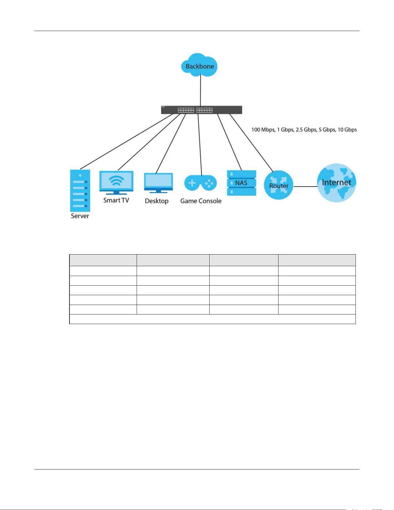
Chapter 1 Getting to Know Your Switch
XGS2220 Series User’s Guide
30
Figure 1 Multi-Gigabit Application
See the following table for the cables required and distance limitation to attain the corresponding
speed.
Note: Make sure to select the correct speed for the port in PORT > Port Setup.
1.1.2 Stacking Mode
The Switch can work in Stacking mode and directly connect to other switches. The switches then
operate together and act as a single switch or a virtual chassis. The stackable switches can be
managed from a master switch in the stack.
Note: To set the Switch to Stacking mode, go to the SYSTEM > Stacking > Stacking Setup
screen.
Note: When the Switch is in Stacking mode, it uses the default static IP address 192.168.1.1.
Note: Make sure the stacking port is connected to the specified media type: SFP+ transceiver
or an SFP+ Direct Attach Copper (DAC10G) that you set in SYSTEM > Stacking >
Stacking Port Setup. Default is SFP+.
Table 2 Cable Types
CABLE TRANSMISSION SPEED MAXIMUM DISTANCE BANDWIDTH CAPACITY
Category 5 100M 100 m 100 MHz
Category 5e or better 1G / 2.5G / 5G* 100 m 100 MHz
Category 6 5G / 10G 100 m / 55 m 250 MHz
Category 6a 10G 100 m 500 MHz
Category 7 10G 100 m 600 MHz
* A high quality Category 5e cable can support 5 Gbps and up to 100 m with no electromagnetic interference.

Chapter 1 Getting to Know Your Switch
XGS2220 Series User’s Guide
31
Figure 2 Stacking Example
1.1.3 Management Modes
NebulaFlex means you can set the Switch to operate in either standalone or cloud mode (but not both
at the same time).
Use the DHCP-assigned IP address to access the Web Configurator. To know the IP address, use the
NCC, the ZON utility, or the console port if available. You can also use the domain name “setup.zyxel” to
access the Web Configurator when you are directly connected to the Switch.
Note: Make sure your computer can connect to a DNS server through the Switch.
Use the Web Configurator to configure and manage the Switch directly in standalone mode or use
Nebula Control Center (NCC) to configure and manage the Switch in cloud mode. The Nebula Control
Center (NCC) is an alternative cloud-based network management system that allows you to remotely
manage and monitor the Switch. You may also access a minimized version of the Web Configurator in
cloud mode.
Nebula Cloud Management
To have Nebula manage the Switch, you must first register it at the Nebula web portal at https://
nebula.zyxel.com, and ensure that Nebula Control Center (NCC) Discovery is enabled in SYSTEM >
Cloud Management in the Switch Web Configurator.
Note: See the Switch’s datasheet for the feature differences between standalone and
Nebula cloud management modes. You can find the Switch’s datasheet at the Zyxel
website.
See the NCC (Nebula Control Center) User’s Guide for how to configure the Switch using Nebula.
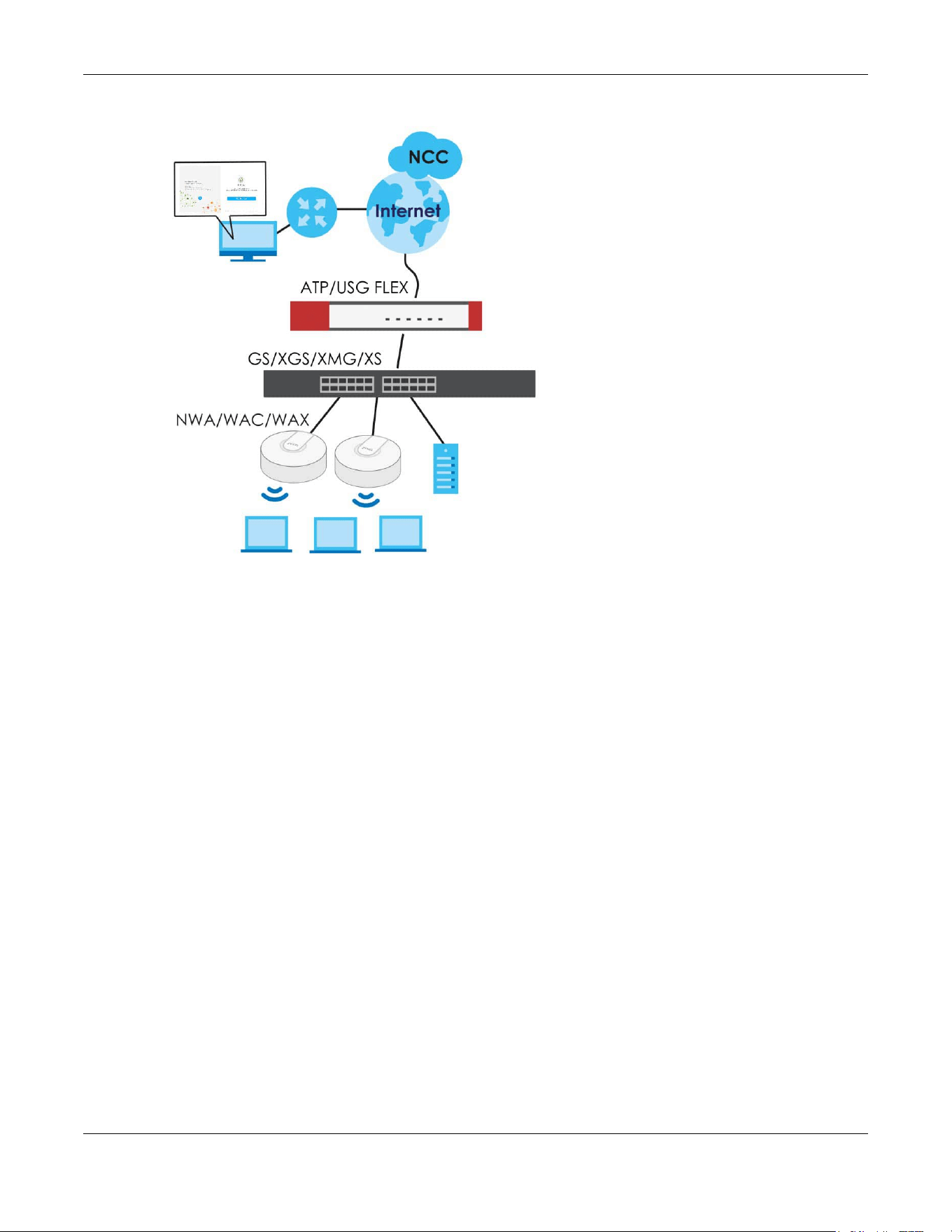
Chapter 1 Getting to Know Your Switch
XGS2220 Series User’s Guide
32
Figure 3 NCC Example Network Topology
1.1.4 Mode Changing
This section describes how to change the Switch’s management mode. Refer to the Switch’s
standalone mode User’s Guide for LED descriptions, including CLOUD LED behavior.
From Standalone to Nebula Cloud Management
To manage your Switch through Nebula, connect the Switch to the Internet, and register it to a site and
organization at the Nebula web portal (https://nebula.zyxel.com).
See the following steps or the Switch Quick Start Guide for registering the Switch.
Go to the NCC to Register the Switch
1 Go to the Nebula web portal in one of three ways.
• Enter https://nebula.zyxel.com in a supported web browser. See the Nebula User’s Guide for more
information about supported browsers.
• Click Visit Nebula in the Switch’s login page.
• Click the Nebula Control Center icon in the upper right of the Switch’s Web Configurator.
2 Click Get Started in the Nebula web portal. Enter your myZyxel account information. You will be
redirected to another screen where you can sign up for a myZyxel account if you do not have one.
3 Create an organization and a site (using the Nebula setup wizard) or select an existing site.

Chapter 1 Getting to Know Your Switch
XGS2220 Series User’s Guide
33
4 Register the Switch by entering its Registration MAC address and serial number and assign it to the site.
The serial number and Registration MAC address can be found in the DASHBOARD screen or the device
back label on the Switch.
Use the Zyxel Nebula Mobile App to Register the Switch
1 Download and open the Zyxel Nebula Mobile app in your mobile device (see Section on page 159 to
download the app). Click Start on the first page. Click Create account to create a myZyxel account or
enter your existing account information to log in.
2 Create an organization and site, or select an existing site using the Zyxel Nebula Mobile app.
3 Select a site and scan the Switch's QR code or manually enter the information to add it to the site. You
can find the QR code:
• On a label on the Switch or
• On its box or
• In the Web Configurator at SYSTEM > Cloud Management.
See Section 3.3 on page 54 for more information about the CLOUD LED or Section Table 33 on page 119
for more information about the Cloud Control Status field in the DASHBOARD screen to see if the Switch
goes into Nebula cloud management mode successfully.
The Switch goes into Cloud mode automatically after it can access the
Nebula web portal and is successfully registered there. Its login
password and settings are then overwritten with what you have
configured in the Nebula web portal. To access the Web Configurator
when the Switch is in Cloud mode, use the Local credentials password
to login.
Note: The Local credentials: Password can be found in Site-wide > Configure > Site settings >
Device configuration in the NCC portal. See the NCC User’s Guide for more
information.
Table 3 Management Method Comparison
MODE ACCESS LOGIN USER NAME LOGIN PASSWORD
LOGIN IP ADDRESS/URL/
DOMAIN NAME
Cloud mode NCC (Nebula
Control Center)
portal
myZyxell account
name
myZyxel account
password
https://nebula.zyxel.com
Web
Configurator
(Local GUI)
admin Local credentials
password
http://setup.zyxel
OR
http://DHCP-assigned IP
OR
a configured static IP address
Note: The Web Configurator (Local GUI) of Cloud mode supports limited features for troubleshooting
use only.
Standalone
mode
Web
Configurator
admin 1234 http://setup.zyxel
OR
http://DHCP-assigned IP
OR
http://192.168.1.1

Chapter 1 Getting to Know Your Switch
XGS2220 Series User’s Guide
34
From Nebula-managed to Standalone
To return to direct management standalone mode, remove (unregister) the Switch from the inventory in
the Nebula web portal.
Note: When you change the Switch’s management mode from Cloud mode to standalone
mode, the Switch will reboot and restore its factory-default settings.
To unregister the Switch:
1 Go to the Nebula Control Center (https://nebula.zyxel.com).
2 Go to the Organization-wide > License & inventory > Devices screen.
3 Select the Switch you want to remove (unregister) from the organization.
4 Click Actions, then click Remove from organization.
It will take a while for the Switch to reboot and reset to factory default.
1.1.5 ZON Utility
With its built-in Web Configurator, including the Neighbor Management feature (Section 13.1 on page
133), viewing, managing and configuring the Switch and its neighboring devices is simplified.
In addition, Zyxel offers a proprietary software program called Zyxel One Network (ZON) Utility, it is a
utility tool that assists you to set up and maintain network devices in a more simple and efficient way.
You can download the ZON Utility at www.zyxel.com and install it on a PC (Windows operation system).
For more information on ZON Utility see Section 4.3 on page 63.
1.1.6 Web Configurator Networked AV Mode
Aside from the Web Configurator in Standard mode, you can switch to Networked AV mode that is
specifically designed to simplify configuration and management of the Switch for AVoIP (Audio-Video
over Internet Protocol) application. In AV over IP, the AV transmitter is the transmitter, the AV receiver is
the receiver, and the matrix switch is a standard IP Switch. See Section 4.4 on page 67 for details on
using the Setup Wizard screen for configuring the Switch’s Networked AV mode’s basic and advanced
settings.
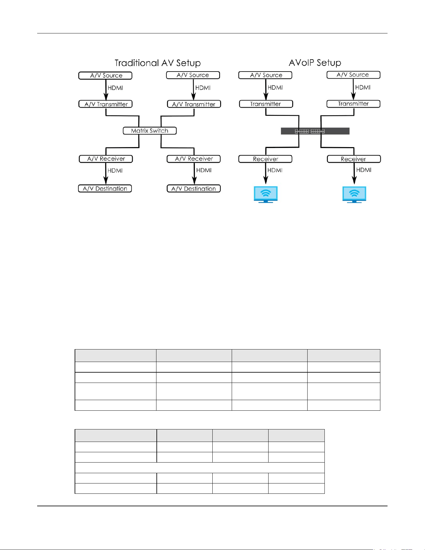
Chapter 1 Getting to Know Your Switch
XGS2220 Series User’s Guide
35
Figure 4 Comparison Between Traditional AV and AVoIP Setups
1.1.7 PoE
The Switch is a Power Sourcing Equipment (PSE) because it provides a source of power through its
Ethernet ports. Each device that receives power through an Ethernet port is a Powered Device (PD).
The Switch can adjust the power supplied to each PD according to the PoE standard the PD supports.
PoE standards are:
• IEEE 802.3af Power over Ethernet (PoE)
• IEEE 802.3at Power over Ethernet (PoE) +
• IEEE 802.3bt Power over Ethernet (PoE) ++
The following table describes the PoE features of the Switch by PoE standard.
Table 4 XGS2220 Series Models and PoE Features
POE FEATURES XGS2220-30HP XGS2220-54HP XGS2220-54FP
IEEE 802.3at PoE+ Ports 1 – 16 Ports 1 – 40 Ports 1 – 40
IEEE 802.3bt PoE++ Ports 17 – 26 Ports 41 – 50 Ports 41 – 50
Power Management Mode Consumption
Classification (default)
Consumption
Classification (default)
Consumption
Classification (default)
PoE Power Budget 400 W 600 W 960 W
Table 5 PoE Standards
PoE FEATURES PoE PoE+ PoE++
IEEE Standard IEEE 802.3af IEEE 802.3at IEEE 802.3bt
PoE Type Type 1 Type 2 Type 3
Switch Port Power
IEEE Power Classification Class 0, 1, 2, 3 Class 4 Class 5, 6
Maximum Power Per Port 15.4 W 30 W 60 W
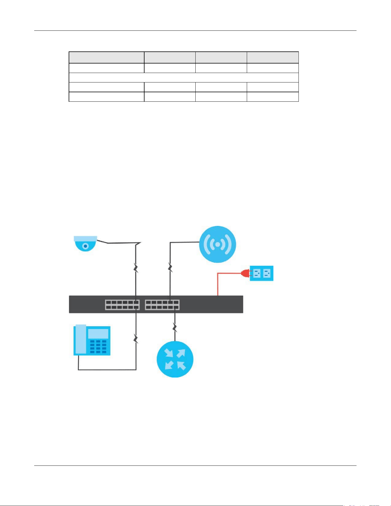
Chapter 1 Getting to Know Your Switch
XGS2220 Series User’s Guide
36
1.2 Example Applications
This section shows a few examples of using the Switch in various network environments. Note that the
Switch in the figure is just an example Switch and not your actual Switch.
1.2.1 PoE Example Application
The following example figure shows a Switch supplying PoE (Power over Ethernet) to Powered Devices
(PDs) such as an IP camera, a wireless router, an IP telephone and a general outdoor router that are not
within reach of a power outlet.
Figure 5 PoE Example Application
1.2.2 Backbone Example Application
The Switch is an ideal solution for small networks where rapid growth can be expected in the near future.
The Switch can be used standalone for a group of heavy traffic users. You can connect computers and
servers directly to the Switch’s port or connect other switches to the Switch.
In this example, all computers can share high-speed applications on the server. To expand the network,
simply add more networking devices such as switches, routers, computers, print servers, and so on.
Port Voltage Range 44 – 57 V 50 – 57 V 50 – 57 V
Cables
Twisted Pairs Used 2-pair 2-pair 4-pair
Supported Cables Cat3 or better Cat5 or better Cat5 or better
Table 5 PoE Standards (continued)
PoE FEATURES PoE PoE+ PoE++

Chapter 1 Getting to Know Your Switch
XGS2220 Series User’s Guide
37
Figure 6 Backbone Application
1.2.3 Bridging or Fiber Optic Uplink Example Application
In this example, the Switch connects different company departments (RD and Sales) to the corporate
backbone. It can alleviate bandwidth contention and eliminate server and network bottlenecks. All
users that need high bandwidth can connect to high-speed department servers through the Switch.
You can provide a super-fast uplink connection by using a Gigabit Ethernet or SFP port on the Switch.
Moreover, the Switch eases supervision and maintenance by allowing network managers to centralize
multiple servers at a single location.
Figure 7 Bridging Application
1.2.4 High Performance Switching Example
The Switch is ideal for connecting two geographically dispersed networks that need high bandwidth. In
the following example, a company uses the 10 Gigabit uplink ports to connect the headquarters to a
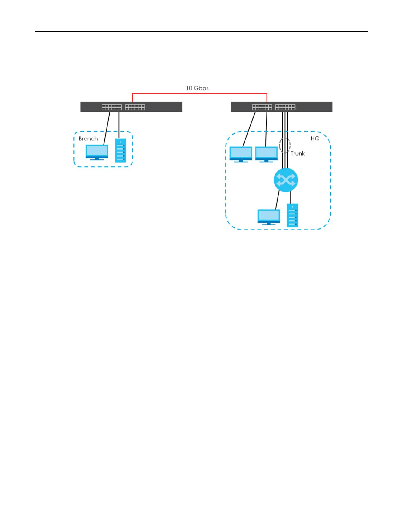
Chapter 1 Getting to Know Your Switch
XGS2220 Series User’s Guide
38
branch office network. Within the headquarters network, a company can use trunking to group several
physical ports into one logical higher-capacity link. Trunking can be used if for example, it is cheaper to
use multiple lower-speed links than to under-utilize a high-speed, but more costly, single-port link.
Figure 8 High Performance Switching
1.2.5 IEEE 802.1Q VLAN Application Examples
A VLAN (Virtual Local Area Network) allows a physical network to be partitioned into multiple logical
networks. Stations on a logical network belong to one or more groups. With VLAN, a station cannot
directly talk to or hear from stations that are not in the same groups unless such traffic first goes through
a router.
1.2.5.1 Tag-based VLAN Example
Ports in the same VLAN group share the same frame broadcast domain thereby increase network
performance through reduced broadcast traffic. VLAN groups can be modified at any time by adding,
moving or changing ports without any re-cabling.
Shared resources such as a server can be used by all ports in the same VLAN as the server. In the
following figure only ports that need access to the server need to be part of VLAN 1. Ports can belong to
other VLAN groups too.
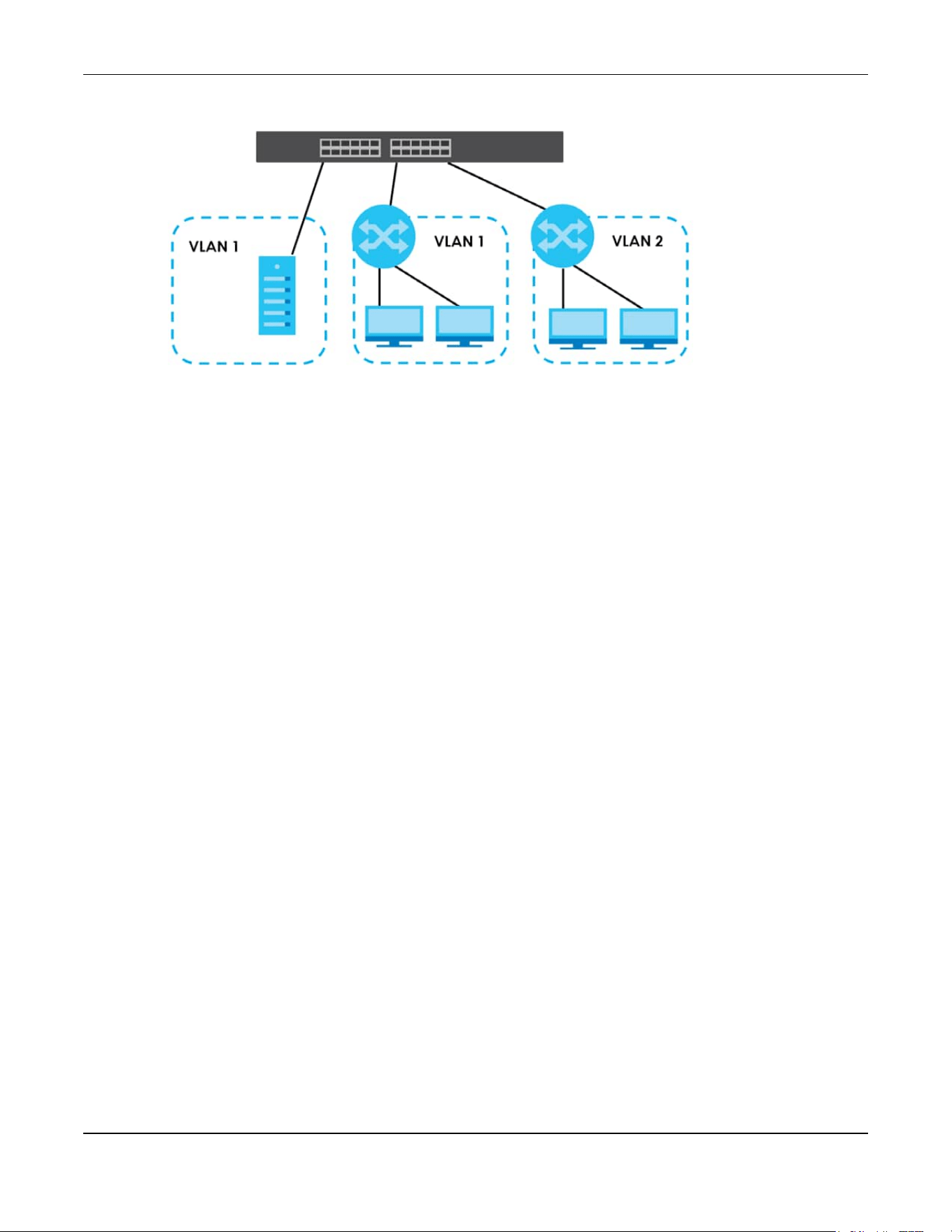
Chapter 1 Getting to Know Your Switch
XGS2220 Series User’s Guide
39
Figure 9 Shared Server Using VLAN Example
1.2.6 IPv6 Support
IPv6 (Internet Protocol version 6), is designed to enhance IP address size and features. The increase in
IPv6 address size to 128 bits (from the 32-bit IPv4 address) allows up to 3.4 x 10
38
IP addresses. At the time
of writing, the Switch supports the following features.
• Static address assignment and stateless auto-configuration
• Neighbor Discovery Protocol (a protocol used to discover other IPv6 devices in a network)
• Remote Management using ping, SNMP, SSH, telnet, HTTP and FTP services
• ICMPv6 to report errors encountered in packet processing and perform diagnostic functions, such as
"ping”
• IPv4/IPv6 dual stack; the Switch can run IPv4 and IPv6 at the same time
• DHCPv6 client and relay
• Multicast Listener Discovery (MLD) snooping and proxy
For more information on IPv6, refer to Appendix C on page 702 and the CLI Reference Guide.
1.3 Ways to Manage the Switch
Use any of the following methods to manage the Switch.
• NCC (Zyxel Nebula Control Center). With the NCC, you can remotely manage and monitor the
Switch through a cloud-based network management system. See the NCC User’s Guide for detailed
information about how to access the NCC and manage your Switch through the NCC. See the NCC
User’s Guide for how to configure Nebula managed devices.
• Web Configurator. This is recommended for everyday management of the Switch using a (supported)
web browser. See Chapter 4 on page 58.
• Command Line Interface. Line commands offer an alternative to the Web Configurator and in some
cases are necessary to configure advanced features. See the CLI Reference Guide.
• FTP. Use File Transfer Protocol for firmware upgrades and configuration backup or restore. See Section
79.3.1 on page 605.
• SNMP. The Switch can be monitored and/or managed by an SNMP manager. See Section 26.6.1 on
page 198.

Chapter 1 Getting to Know Your Switch
XGS2220 Series User’s Guide
40
• Cluster Management. Cluster Management allows you to manage multiple switches through one
switch, called the cluster manager. See Chapter 79 on page 608.
• ZON Utility. ZON Utility is a program designed to help you deploy and perform initial setup on a
network more efficiently. See Section 4.3 on page 63.
1.4 Good Habits for Managing the Switch
Do the following regularly to make the Switch more secure and to manage the Switch more effectively.
• Change the password. Use a password that is not easy to guess and that consists of different types of
characters, such as numbers and letters.
• Write down the password and put it in a safe place.
• Back up the configuration (and make sure you know how to restore it). Restoring an earlier working
configuration may be useful if the device becomes unstable or even crashes. If you forget your
password, you will have to reset the Switch to its factory default settings. If you backed up an earlier
configuration file, you would not have to totally re-configure the Switch. You could simply restore your
last configuration.

XGS2220 Series User’s Guide
41
CHAPTER 2
Hardware Installation and
Connection
2.1 Installation Scenarios
This chapter shows you how to install and connect the Switch.
The Switch can be:
• Placed on a desktop.
• Rack-mounted on a standard EIA rack.
2.2 Safety Precautions
Please observe the following before using the Switch:
• It is recommended to ask an authorized technician to attach the Switch on a desk or to the rack or
wall. Use the proper screws to prevent damage to the Switch. See the Installation Requirements
sections in this chapter to know the types of screws and screwdrivers for each mounting method.
• Make sure there is at least 2 cm of clearance on the top and bottom of the Switch, and at least 5 cm
of clearance on all four sides of the Switch. This allows air circulation for cooling.
• Do NOT block the ventilation holes nor store cables or power cords on the Switch. Allow clearance for
the ventilation holes to prevent your Switch from overheating. This is especially crucial when your
Switch does not have fans. Overheating could affect the performance of your Switch, or even
damage it.
• The surface of the Switch could be hot when it is functioning. Do NOT put your hands on it. You may
get burned. This could happen especially when you are using a fanless Switch.
• The Switches with fans are not suitable for use in locations where children are likely to be present.
To start using the Switch, simply connect the power cables to turn it on.
2.3 Freestanding Installation Procedure
1 Make sure the Switch is clean and dry.
2 Remove the adhesive backing from the rubber feet.
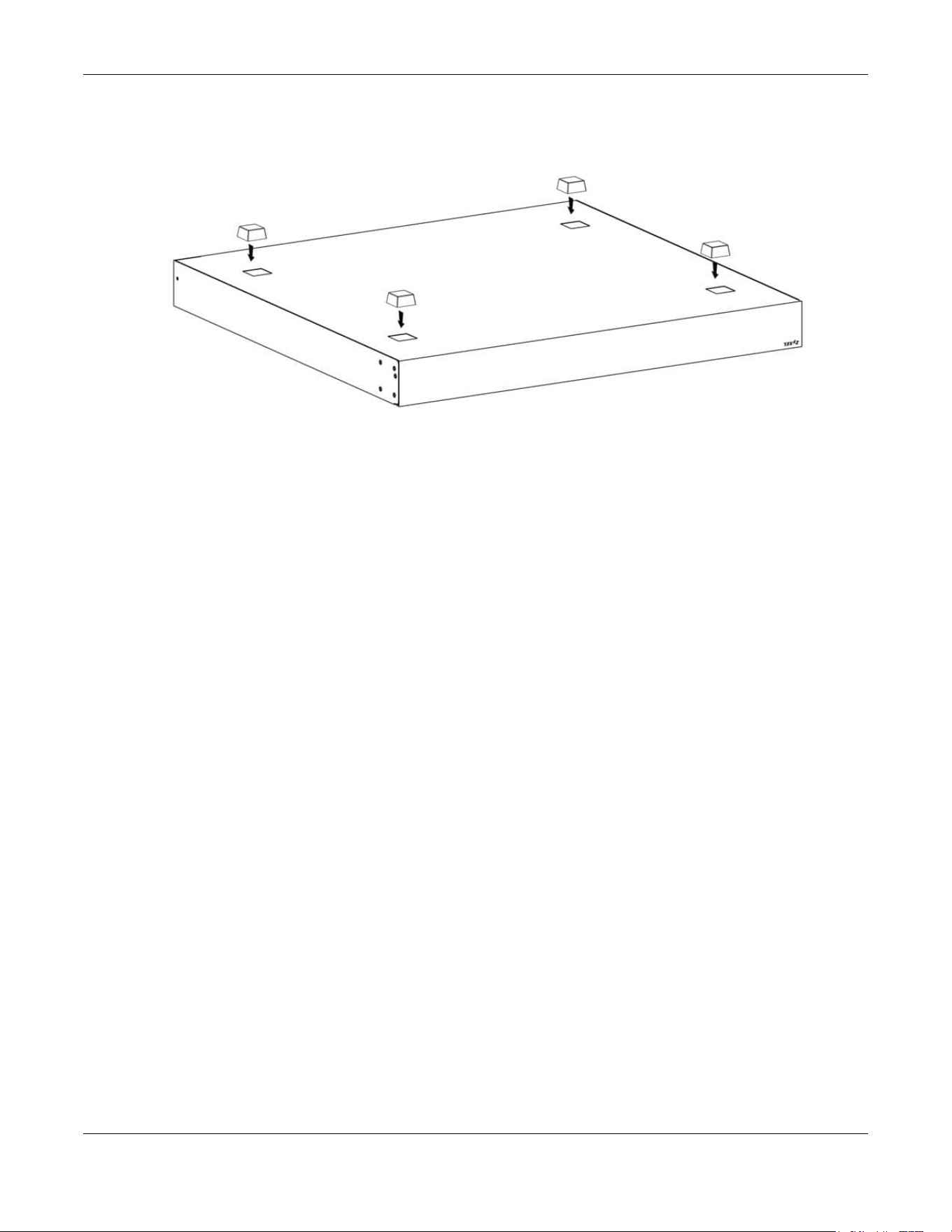
Chapter 2 Hardware Installation and Connection
XGS2220 Series User’s Guide
42
3 Attach the rubber feet to each corner on the bottom of the Switch. These rubber feet help protect the
Switch from shock or vibration and ensure space between devices when stacking.
Figure 10 Attaching Rubber Feet
4 Set the Switch on a smooth, level surface strong enough to support the weight of the Switch and the
connected cables. Make sure there is a power outlet nearby.
Cautions:
• Avoid stacking fanless Switches to prevent overheating.
• Ensure enough clearance around the Switch to allow air circulation for cooling.
• Do NOT remove the rubber feet as it provides space for air circulation.
2.4 Mounting the Switch on a Rack
The Switch can be mounted on an EIA standard size, 19-inch rack or in a wiring closet with other
equipment. Follow the steps below to mount your Switch on a standard EIA rack using a rack-mounting
kit.
Note: Make sure there is enough clearance between each equipment on the rack for air
circulation.
2.4.1 Installation Requirements
• Two mounting brackets.
• Eight M3 flat head screws and a #2 Philips screwdriver.
• Four M5 flat head screws and a #2 Philips screwdriver.
2.4.2 Precautions
• Make sure the rack will safely support the combined weight of all the equipment it contains. The
maximum weight a bracket can hold is 21.5 kg.
• Make sure the position of the Switch does not make the rack unstable or top-heavy. Take all
necessary precautions to anchor the rack securely before installing the unit.

Chapter 2 Hardware Installation and Connection
XGS2220 Series User’s Guide
43
2.4.3 Attaching the Mounting Brackets to the Switch
1 Position a mounting bracket on one side of the Switch, lining up the four screw holes on the bracket with
the screw holes on the side of the Switch.
Figure 11 Attaching the Mounting Brackets
2 Using a #2 Philips screwdriver, install the M3 flat head screws through the mounting bracket holes into
the Switch.
3 Repeat steps 1 and 2 to install the second mounting bracket on the other side of the Switch.
4 You may now mount the Switch on a rack. Proceed to the next section.
2.4.4 Mounting the Switch on a Rack
1 Position a mounting bracket (that is already attached to the Switch) on one side of the rack, lining up
the two screw holes on the bracket with the screw holes on the side of the rack.
Figure 12 Mounting the Switch on a Rack
2 Using a #2 Philips screwdriver, install the M5 flat head screws through the mounting bracket holes into

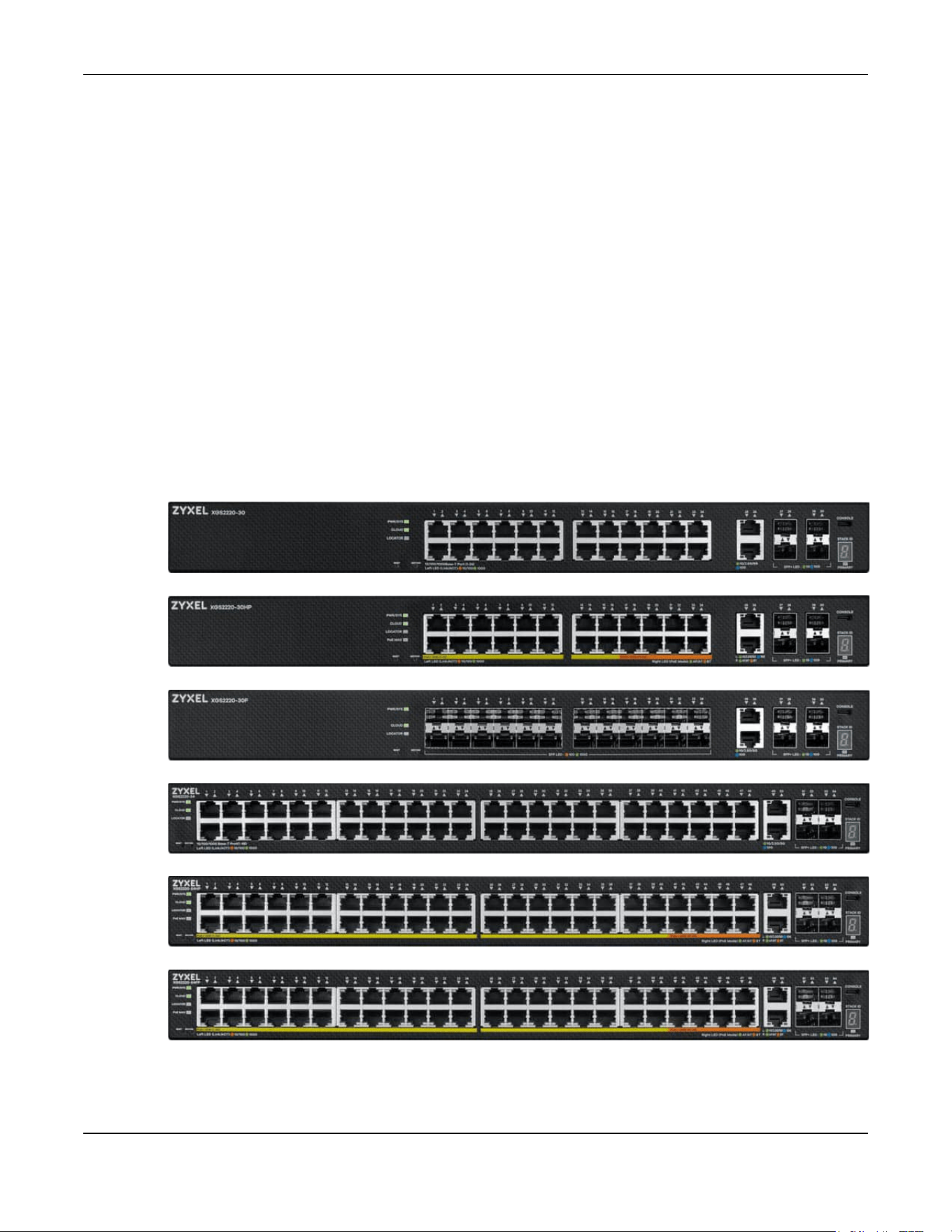
Chapter 3 Hardware Panels
XGS2220 Series User’s Guide
45
CHAPTER 3
Hardware Panels
This chapter describes the front panel and rear panel of the Switch and shows you how to make the
hardware connections.
3.1 Front Panel Connections
The following figures show the front panels of the Switch.
Figure 13 Front Panel: XGS2220-30
Figure 14 Front Panel: XGS2220-30HP
Figure 15 Front Panel: XGS2220-30F
Figure 16 Front Panel: XGS2220-54
Figure 17 Front Panel: XGS2220-54HP
Figure 18 Front Panel: XGS2220-54FP

Chapter 3 Hardware Panels
XGS2220 Series User’s Guide
46
The following table describes the ports.
3.1.1 Multi-Gigabit Ethernet Ports
The Switch has 1000Base-T auto-negotiating, auto-crossover Ethernet ports. In 10/100/1000 Mbps Gigabit
Ethernet, the speed can be 10 Mbps, 100 Mbps or 1000 Mbps. The duplex mode can be half duplex or
full duplex.
An auto-negotiating port can detect and adjust to the optimum Ethernet speed (10/100/1000 Mbps)
and duplex mode (full duplex or half duplex) of the connected device.
An auto-crossover (auto-MDI/MDI-X) port automatically works with a straight-through or crossover
Ethernet cable.
When auto-negotiation is turned on, an Ethernet port negotiates with the peer automatically to
determine the connection speed and duplex mode. If the peer Ethernet port does not support auto-
Table 6 Front Panel Connections
CONNECTOR DESCRIPTION
24/48 1000Base-T
RJ-45 Ethernet Ports
These are 10/100/1000Base-T auto-negotiating and auto-crossover Ethernet ports.
Connect these ports to a computer, a hub, a router, or an Ethernet switch.
2 10GBase-T RJ-45
Ethernet Ports
These are 1/2.5/5/10G auto-negotiating and auto-crossover Ethernet ports.
Connect these ports to a gaming computer, a NAS (network-attached storage), or a server.
16/40 1000Base-T
RJ-45 PoE Ports
These are 10/100/1000Base-T auto-negotiating and auto-crossover IEEE802.3at PoE+ 30 W
ports.
Connect these ports to a PTZ (pan, tilt and zoom) camera, a WiFi 6 (802.11ax) router, a WiFi 6
(802.11ax) AP, or an Ethernet switch.
8 1000Base-T RJ-45
PoE Ports
These are 10/100/1000Base-T auto-negotiating and auto-crossover IEEE802.3bt PoE++ 60 W
ports.
Connect these ports to a PTZ (pan, tilt and zoom) camera, a WiFi 6 (802.11ax) router, a WiFi 6
(802.11ax) AP, or an Ethernet switch.
2 10GBase-T RJ-45
PoE Ports
These are 1G, 2.5G, 5G, and 10G auto-negotiating and auto-crossover IEEE802.3bt PoE++ 60
W ports.
Connect these ports to a PTZ (pan, tilt and zoom) camera, a WiFi 6 (802.11ax) router, a WiFi 6
(802.11ax) AP, or an Ethernet switch.
4 1/10G SFP+ Slots Use SFP+ transceivers in these ports for high-bandwidth backbone connections. You can
also insert an SFP+ Direct Attach Copper (DAC) in the SFP+ slot.
Reset Press the RESET button to reboot the Switch without turning the power off. See Section 3.3 on
page 54 for more information about the LED behavior.
Restore
IN STANDALONE MODE
Press the RESTORE button for 3 to 7 seconds to have the Switch automatically reboot and
restore the last-saved custom default file. See Section 3.3 on page 54 for more information
about the LED behavior.
Press the RESTORE button for more than 7 seconds to have the Switch automatically reboot
and restore the factory default file. See Section 3.3 on page 54 for more information about
the LED behavior.
IN NEBULA CLOUD MODE
Press the RESTORE button for more than 7 seconds to have the Switch automatically reboot
and restore the factory default file.

XGS2220 Series User’s Guide
47
negotiation or turns off this feature, the Switch determines the connection speed by detecting the signal
on the cable and using half duplex mode. When the Switch’s auto-negotiation is turned off, an Ethernet
port uses the pre-configured speed and duplex mode when making a connection, thereby requiring
you to make sure that the settings of the peer Ethernet port are the same in order to connect.
3.1.1.1 Default Ethernet Negotiation Settings
The factory default negotiation settings for the Gigabit ports on the Switch are:
• Speed: Auto
•Duplex: Auto
• Flow control: Off
• Link Aggregation: Disabled
3.1.1.2 Auto-crossover
All ports support auto-crossover, that is auto-MDIX ports (Media Dependent Interface Crossover), so you
may use either a straight-through Ethernet cable or crossover Ethernet cable for all Gigabit port
connections. Auto-crossover ports automatically sense whether they need to function as crossover or
straight ports, so crossover cables can connect both computers and switches or hubs.
3.1.2 SFP/SFP+ Slots
These are four slots for Small Form-Factor Pluggable (SFP) or SFP+ modules, such as an SFP or SFP+
transceiver. The SFP+ (SFP Plus) is an enhanced version of the SFP and supports data rates of 10 Gbps. A
transceiver is a single unit that houses a transmitter and a receiver. Use a transceiver to connect a fiber
optic cable to the Switch. The Switch does not come with transceivers. You must use transceivers that
comply with the Small Form-Factor Pluggable (SFP) Transceiver MultiSource Agreement (MSA). See the
SFF committee’s INF-8074i specification Rev 1.0 for details.
You can change transceivers while the Switch is operating. You can use different transceivers to
connect to Ethernet switches with different types of fiber optic connectors.
• Type: SFP or SFP+ connection interface
• Connection speed: 1 or 10 Gigabit per second (Gbps)
WARNING! To avoid possible eye injury, do not look into an operating
fiber optic module’s connectors.
HANDLING! All transceivers are static sensitive. To prevent damage from
electrostatic discharge (ESD), it is recommended you attach an ESD
preventive wrist strap to your wrist and to a bare metal surface when
you install or remove a transceiver.
STORAGE! All modules are dust sensitive. When not in use, always keep
the dust plug on. Avoid getting dust and other contaminant into the
optical bores, as the optics do not work correctly when obstructed with
dust.
3.1.2.1 Transceiver Installation
Use the following steps to install a transceiver.
1 Attach an ESD preventive wrist strap to your wrist and to a bare metal surface.

Chapter 3 Hardware Panels
XGS2220 Series User’s Guide
48
2 Align the transceiver in front of the slot opening.
3 Make sure the latch is in the lock position (latch styles vary), then insert the transceiver into the slot with
the exposed section of PCB board facing down.
4 Press the transceiver firmly until it clicks into place.
5 The Switch automatically detects the installed transceiver. Check the LEDs to verify that it is functioning
properly.
6 Remove the dust plugs from the transceiver and cables (dust plug styles vary).
7 Identify the signal transmission direction of the fiber optic cables and the transceiver. Insert the fiber
optic cable into the transceiver.
Figure 19 Latch in the Lock Position
Figure 20 Transceiver Installation Example
Figure 21 Connecting the Fiber Optic Cables
3.1.2.2 Transceiver Removal
Use the following steps to remove an SFP transceiver.
1 Attach an ESD preventive wrist strap to your wrist and to a bare metal surface on the chassis.
2 Remove the fiber optic cables from the transceiver.
3 Pull out the latch and down to unlock the transceiver (latch styles vary).
Note: Make sure the transceiver’s latch is pushed all the way down, so the transceiver can be
pulled out successfully.
4 Pull the latch, or use your thumb and index finger to grasp the tabs on both sides of the transceiver, and
carefully slide it out of the slot.

Chapter 3 Hardware Panels
XGS2220 Series User’s Guide
49
Note: Do NOT pull the transceiver out by force. You could damage it. If the transceiver will not
slide out, grasp the tabs on both sides of the transceiver with a slight up or down motion
and carefully slide it out of the slot. If unsuccessful, contact Zyxel Support to prevent
damage to your Switch and transceiver.
5 Insert the dust plug into the ports on the transceiver and the cables.
Figure 22 Removing the Fiber Optic Cables
Figure 23 Opening the Transceiver’s Latch Example
Figure 24 Transceiver Removal Example
3.1.3 Console Port
Without Access L3 License
With instructions from customer support, This USB Type C connector is for troubleshooting only.
With Access L3 License
When the Access L3 license is activated in your Switch, connect this port to your computer (using an USB
Type C console cable) if you want to configure the Switch using the command line interface (CLI)
through the console port.
3.2 Rear Panel
The following figures show the rear panel of the Switch. The rear panel contains:
Figure 25 Rear Panel: XGS2220-30

Chapter 3 Hardware Panels
XGS2220 Series User’s Guide
50
Figure 26 Rear Panel: XGS2220-30HP
Figure 27 Rear Panel: XGS2220-30F
Figure 28 Rear Panel: XGS2220-54
Figure 29 Rear Panel: XGS2220-54HP
Figure 30 Rear Panel: XGS2220-54FP
3.2.1 Grounding
Grounding is a safety measure to direct excess electric charge to the ground. It prevents damage to
the Switch, and protects you from electrocution. Use the grounding screw on the rear panel and the
ground wire of the AC power supply to ground the Switch.
The grounding terminal and AC power ground where you install the Switch must follow your country’s
regulations. Qualified service personnel must ensure the building’s protective earthing terminals are
valid terminals.
Installation of Ethernet cables must be separate from AC power lines. To avoid electric surge and
electromagnetic interference, use a different electrical conduit or raceway (tube/trough or enclosed
conduit for protecting electric wiring) that is 15 cm apart, or as specified by your country’s electrical
regulations.
Any device that is located outdoors and connected to this product must be properly grounded and
surge protected. To the extent permissible by your country’s applicable law, failure to follow these
guidelines could result in damage to your Switch which may not be covered by its warranty.
Note: The specification for surge or ESD protection assumes that the Switch is properly
grounded.
1 Remove the M4 ground screw from the Switch’s rear panel.
2 Secure a green or yellow ground cable (16 AWG or smaller) to the Switch's rear panel using the M4
ground screw.
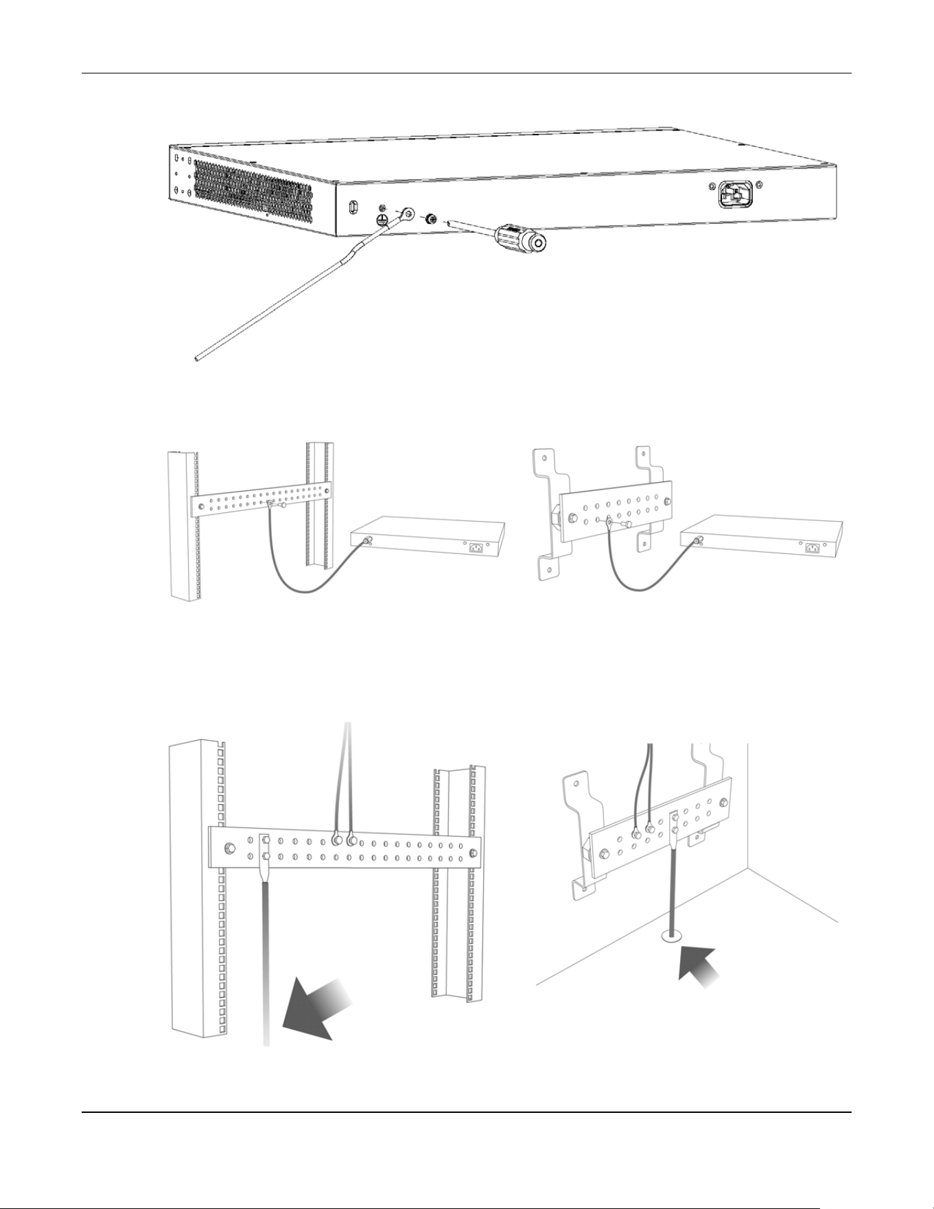
Chapter 3 Hardware Panels
XGS2220 Series User’s Guide
51
Figure 31 Grounding
3 Attach the other end of the ground cable to a grounding bar located on the rack where you install the
Switch or to an on-site grounding terminal.
Figure 32 Attach Ground Cable to Grounding Bar or On-site Grounding Terminal
4 The grounding terminal of the server rack or on-site grounding terminal must also be grounded and
connected to the building’s main grounding electrode. Make sure the grounding terminal is connected
to the buildings grounding electrode and has an earth resistance of less than 10 ohms, or according to
your country’s electrical regulations.
Figure 33 Connecting to the Building’s Main Grounding Electrode
If you are uncertain that suitable grounding is available, contact the appropriate electrical inspection
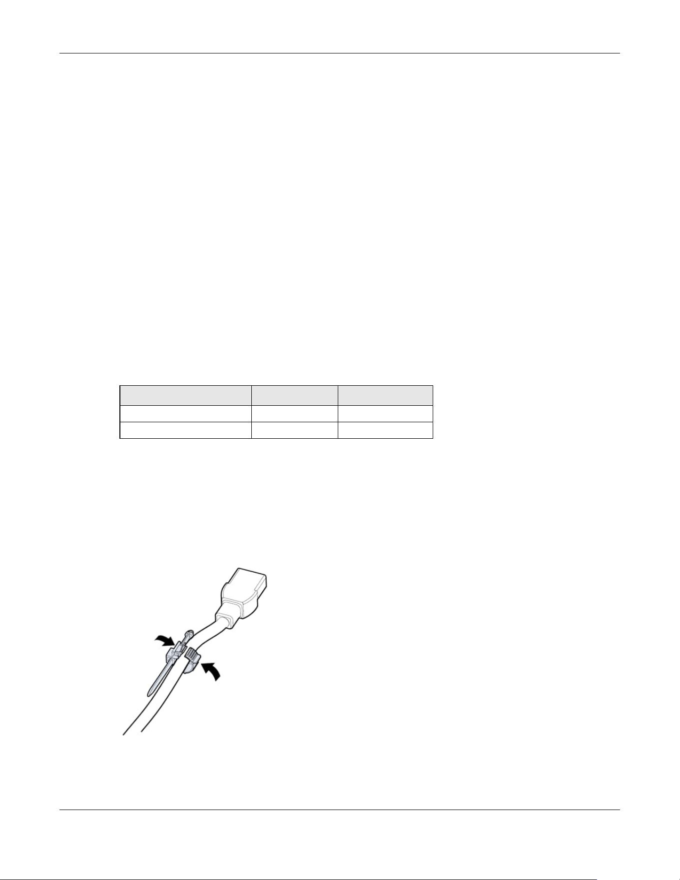
Chapter 3 Hardware Panels
XGS2220 Series User’s Guide
52
authority or an electrician.
This device must be grounded. Do this before you make other
connections.
3.2.2 AC Power Connection
Note: Make sure you are using the correct power source as shown on the panel and that no
objects obstruct the airflow of the fans (located on the side of the unit).
To connect power to the Switch, insert the female end of the power cord to the AC power receptacle
on the rear panel. Connect the other end of the supplied power cord to a power outlet.
Power Cord Requirement (XGS2220-54HP / XGS2220-54FP)
Make sure to use the provided or designated power cord for your
Switch.
The following table describes the power cord requirements for XGS2220-54HP / XGS2220-54FP.
Note: If you need to replace the power cord, contact your local vendor.
Installing the Retainer Clip
Install the retainer clip to prevent accidental removal of the power cord.
1 Loosely wrap the clip on the retainer to the power cord.
2 Push the pronged-end of the retainer clip into the Retainer Holder hole until it locks into place.
Table 7 XGS2220-54HP / XGS2220-54FP Power Cord Specifications
COUNTRIES SPECIFICATION SUPPLY VOLTAGE
Europe and United Kingdom 18 AWG 230 V
North America 14 AWG 110 V
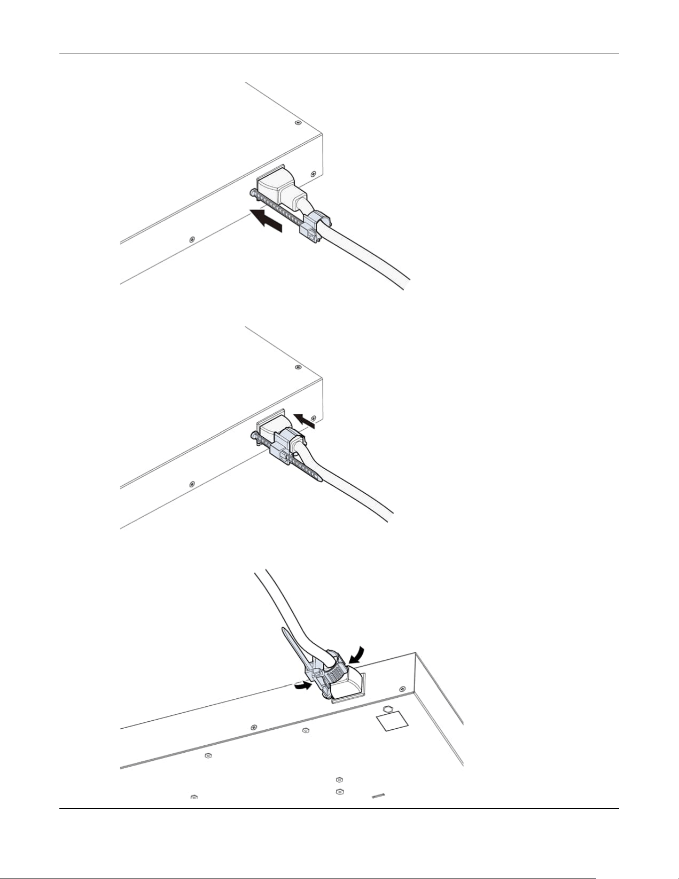
Chapter 3 Hardware Panels
XGS2220 Series User’s Guide
53
3 Slide the clip up to the end of the power cord.
4 Close the clip tightly around the power cord until secure.

Chapter 3 Hardware Panels
XGS2220 Series User’s Guide
54
3.3 LEDs
After you connect the power to the Switch, view the LEDs to ensure proper functioning of the Switch
and as an aid in troubleshooting.
Table 8 LED Descriptions
LED COLOR STATUS DESCRIPTION
PWR/SYS Green On The Switch is on and functioning properly.
Blinking The Switch is rebooting and performing self-diagnostic tests.
Yellow On The Switch is functioning abnormally, FAN status alert/error, or
the system power detected is under 10.8 V.
Blinking The Switch is returning to its factory default configuration
settings.
Off The Switch is not receiving power from the power source.
CLOUD Green On The Switch has successfully connected to the NCC (Nebula
Control Center).
Blinking The Switch cannot connect to the NCC because it is not
registered. Please register the Switch with NCC.
Yellow On The Switch is registered with NCC but cannot connect to the
NCC. Please check the Internet connection of the Switch.
Blinking The Switch is not registered with NCC and cannot connect to
the NCC. Please check the Internet connection of the Switch
and register the Switch with NCC.
Off The Switch is operating in standalone mode. Nebula Control
Center (NCC) Discovery is disabled in SYSTEM > Cloud
Management in the Switch Web Configurator.
LOCATOR Blue On The Switch is uploading firmware. While the Switch is doing this,
do not turn off the power.
Blinking Shows the actual location of the Switch between several
devices in a rack. The default timer is 30 minutes when you are
configuring the Switch.
Off The locator is not functioning or malfunctioning.
PoE MAX
(XGS2220-30HP /
XGS2220-54HP /
XGS2220-54FP)
Red On PoE power usage is more than 95 percent of the power
supplied budget.
Yellow On PoE power usage is below 95 percent of the power supplied
budget, but over 80 percent of the power supplied budget.
Off PoE power usage is below 80 percent of the power supplied
budget.
STACK ID The LED is showing the Stack ID number of the Switch.
ID 0 means it is a standalone Switch.
PRIMARY Green On The Switch is acting as a standalone switch or the master in
stacking.
Yellow On An error occurred when the Switch is selected as the master
member in a stack.
Off The Switch is acting as a non-master member in a stack.
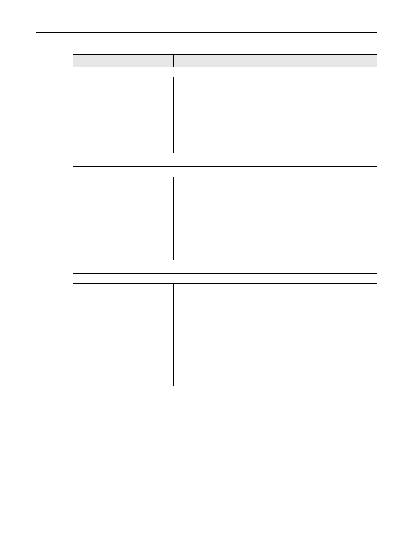
Chapter 3 Hardware Panels
XGS2220 Series User’s Guide
55
LED COLOR STATUS DESCRIPTION
10M/100M/1000M Base-T Ports
Link / ACT
1 – 24
(XGS2220-30 /
XGS2220-30HP)
1 – 48
(XGS2220-54 /
XGS2220-54HP /
XGS2220-54FP)
Green On The link to a 1000M Ethernet network is up.
Blinking The Switch is transmitting/receiving to/from a 1000M Ethernet
network.
Yellow On The link to a 10M/100M Ethernet network is up.
Blinking The Switch is transmitting/receiving to/from a 10M/100M
Ethernet network.
Off The link to an Ethernet network is down.
1G/2.5G/5G/10G Base-T Ports
Link / ACT
25 – 26
(XGS2220-30 /
XGS2220-30HP /
XGS2220-30F)
49 – 50
(XGS2220-54 /
XGS2220-54HP /
XGS2220-54FP)
Blue On The link to a 10G Ethernet network is up.
Blinking The Switch is transmitting/receiving to/from a 10G Ethernet
network.
Green On The link to a 1G/2.5G/5G Ethernet network is up.
Blinking The Switch is transmitting/receiving to/from a 1G/2.5G/5G
Ethernet network.
Off The link to an Ethernet network is down.
PoE Mode
1 – 16
(XGS2220-30HP)
1 – 40
(XGS2220-54HP /
XGS2220-54FP)
Green On Power supplied to all PoE Ethernet ports meets the IEEE 802.3at
or IEEE 802.3af standard.
Off There is no power supplied.
17 – 26
(XGS2220-30HP)
41 – 50
(XGS2220-54HP /
XGS2220-54FP)
Yellow On Power supplied to all PoE Ethernet ports meets the IEEE 802.3bt
standard.
Green On Power supplied to all PoE Ethernet ports meets the IEEE 802.3at
/ IEEE 802.3af standards.
Off There is no power supplied.
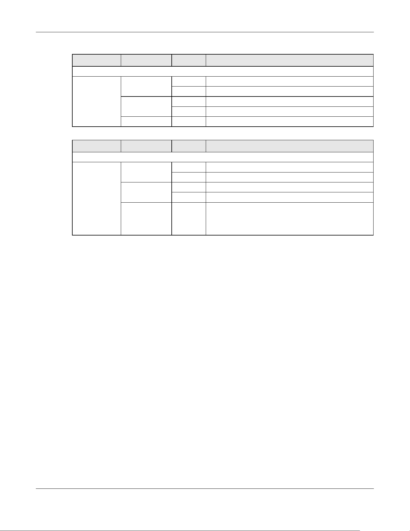
Chapter 3 Hardware Panels
XGS2220 Series User’s Guide
56
LED COLOR STATUS DESCRIPTION
1G SFP Slots
Link / ACT
1 – 24
(XGS2220-30F)
Green On The port has a successful 1000M connection.
Blinking The port is transmitting or receiving data at 1000M.
Yellow On The port has a successful 100M connection.
Blinking The port is transmitting or receiving data at 100M.
Off This link is disconnected.
LED COLOR STATUS DESCRIPTION
1G/10G SFP+ Slots
Link / ACT
27 – 30
(XGS2220-30 /
XGS2220-30HP /
XGS2220-30F)
51 – 54
(XGS2220-54 /
XGS2220-54HP /
XGS2220-54FP)
Blue On The port has a successful 10G connection.
Blinking The port is transmitting or receiving data at 10G.
Green On The port has a successful 1000M connection.
Blinking The port is transmitting or receiving data at 1000M.
Off This link is disconnected.

57
PART II
Technical Reference

XGS2220 Series User’s Guide
58
CHAPTER 4
Web Configurator
4.1 Overview
This section introduces the configuration and functions of the Web Configurator.
The Web Configurator is an HTML-based management interface that allows easy system setup and
management through Internet browser. Use a browser that supports HTML5, such as Microsoft Edge,
Mozilla Firefox, or Google Chrome. The recommended minimum screen resolution is 1024 by 768 pixels.
In order to use the Web Configurator you need to allow:
• Web browser pop-up windows on your computer.
• JavaScript (enabled by default).
• Java permissions (enabled by default).
4.2 System Login
1 Start your web browser.
2 The Switch is a DHCP client by default. Type “http://DHCP-assigned IP” in the Location or Address field.
Press [ENTER].
Note: You can always use the domain name “setup.zyxel” to access the Web Configurator
whether the Switch is using a DHCP-assigned IP or static IP address. This requires your
computer to be directly connected to the Switch. Make sure your computer can
connect to a DNS server through the Switch.
If the Switch is not connected to a DHCP server, enter “http://” and the static IP address of the Switch
(for example, the default management IP address is 192.168.1.1 through an in-band port) in the Location
or Address field. Press [ENTER]. Your computer must be in the same subnet in order to access this website
address.
Also, you can use the ZON Utility to check your Switch’s IP address. See Section 4.3 on page 63 for more
information on the ZON utility.
3 The Login screen appears.

Chapter 4 Web Configurator
XGS2220 Series User’s Guide
59
Figure 34 Web Configurator: Login
4 Click the Visit Nebula button if you want to open the Zyxel Nebula Control Center (NCC) login page in a
new tab or window. The NCC is a cloud-based network management system that allows you to
remotely manage and monitor the Switch. See Section 1.1.4 on page 32 for information on changing
your Switch to Nebula Cloud management.
Figure 35 Visit Nebula
5 Alternatively, click Login to log into the Web Configurator to manage the Switch directly. The default
user name is admin and associated default password is 1234.
6 The Select Mode screen appears.
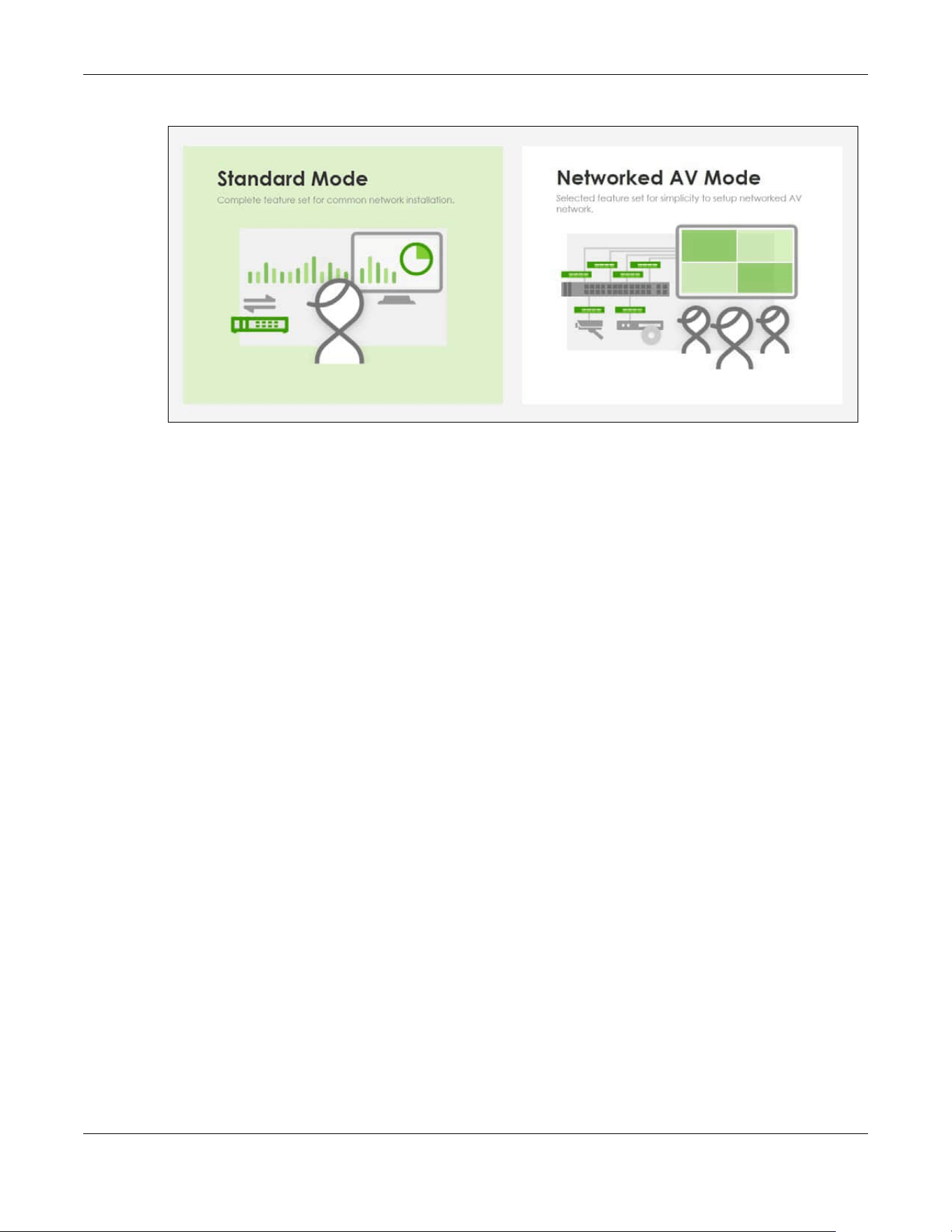
Chapter 4 Web Configurator
XGS2220 Series User’s Guide
60
Figure 36 Select Mode
7 Select the Web Configurator in Standard Mode that has a complete set of configuration for network
installation. Or select the Web Configurator in Networked AV Mode that has a set of menus specifically
designed to simplify configuration and management of the Switch for AVoIP (Audio-Video over Internet
Protocol) application.
8 If you select Standard Mode, go directly to step 10.
9 The Setup Wizard screen will appear after selecting the Networked AV Mode. You can use the Setup
Wizard screen to configure the Switch’s Networked AV mode’s basic or advanced settings (see Section
4.4 on page 67 for details).
• Use the Basic Settings to configure networked AV operation on management VLAN. Such as the
Switches’ IP address, DNS server, system password, SNMP community, accept or skip the default
Networked AV mode settings, and view a summary of the basic settings.
• Use the Advanced Settings for networks that wants to separate networked AV VLAN from
management VLAN, specify which ports connect to AVoIP application, and for setting link
aggregation across switches.
Once you click the Finish button, the settings configured in the Setup Wizard screen will overwrite the
existing settings.
Otherwise, click the Exit button. If you want to open the Setup Wizard screen later, click the Wizard icon
in the upper right hand corner of the Web Configurator in Networked AV mode.
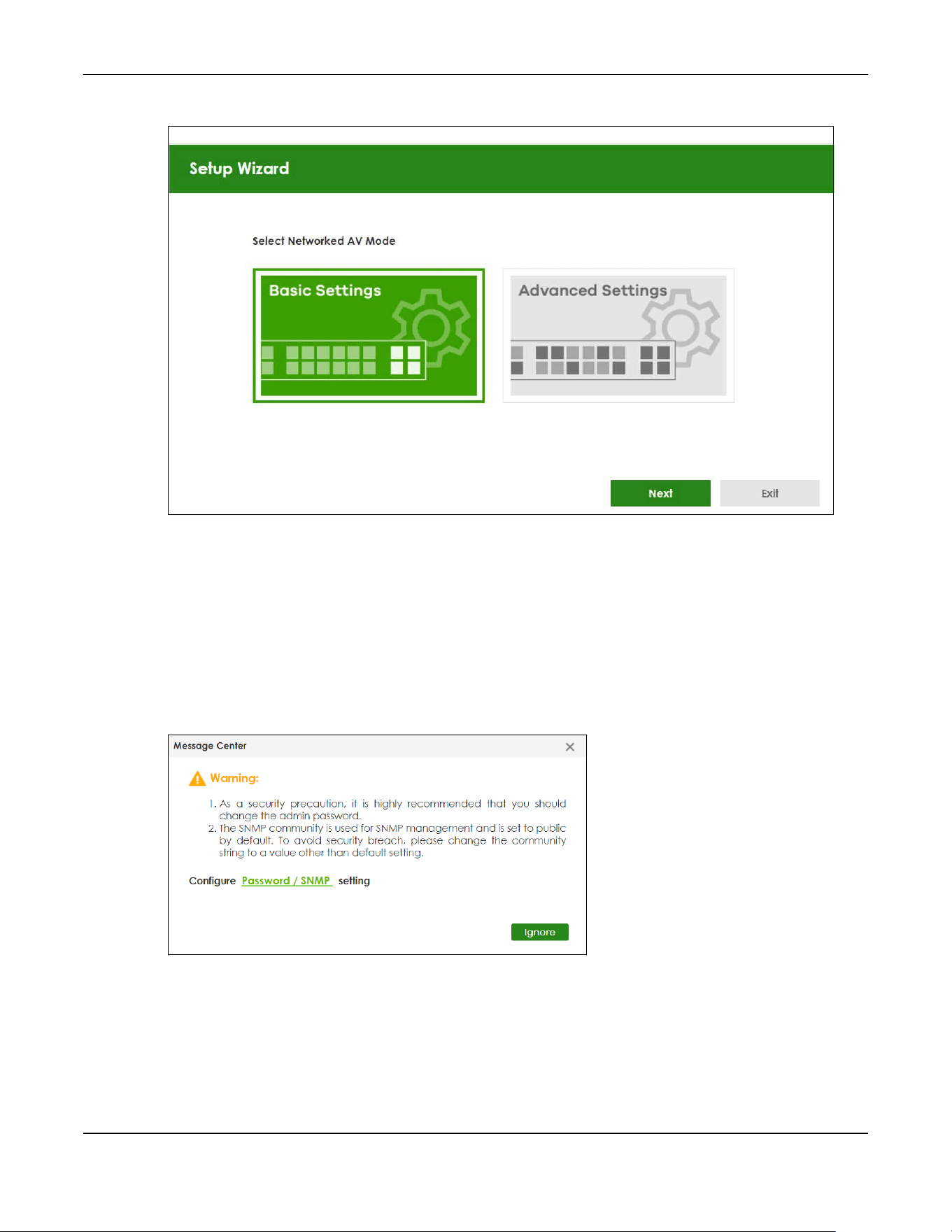
Chapter 4 Web Configurator
XGS2220 Series User’s Guide
61
Figure 37 Web Configurator: Wizard
10 If you did not change the default administrator password and/or SNMP community values, a warning
screen displays each time you log into the Web Configurator and select Standard Mode. Click Password
/ SNMP to open a screen where you can change the administrator password and SNMP community
string simultaneously. Otherwise, click Ignore to close it.
If you log into the Web Configurator and select Networked AV Mode, open the screen in the Wizard >
Step 2 Password to change the administrator password and SNMP community string. Click Finish on the
last step of the Wizard to save your settings.
Password/SNMP Setting
Figure 38 Web Configurator: Warning

Chapter 4 Web Configurator
XGS2220 Series User’s Guide
62
Figure 39 Web Configurator: Password/SNMP
Note: The input string of any field in this screen should not contain [ ? ], [ | ], [ ' ], [ " ], or [ , ].
In the Password fields, [ space ] is also not allowed.
Change the default administrator and/or SNMP passwords, and then click Apply to save your changes.
Table 9 Web Configurator: Password/SNMP
LABEL DESCRIPTION
Password – Administrator
This is the default administrator account with the “admin” user name. You cannot change the default administrator
user name.
Old Password Enter the existing system password (1234 is the default password when shipped).
New Password Enter your new system password. Up to 32 printable ASCII characters are allowed for the new
password.
Retype to confirm Re-enter your new system password for confirmation.
SNMP – General Setting
Use this section to specify the SNMP version and community (password) values.
Version Select the SNMP version for the Switch. The SNMP version on the Switch must match the version
on the SNMP manager. Choose SNMP version 2c (v2c), SNMP version 3 (v3) or both (v3v2c).
Note: SNMP version 2c is backwards compatible with SNMP version 1.
Get Community Enter the Get Community string, which is the password for the incoming Get- and GetNext-
requests from the management station. The Get Community string is only used by SNMP
managers using SNMP version 2c or lower.
Set Community Enter the Set Community string, which is the password for the incoming Set- requests from the
management station.
The Set Community string is only used by SNMP managers using SNMP version 2c or lower.
Trap Community Enter the Trap Community string, which is the password sent with each trap to the SNMP
manager.
The Trap Community string is only used by SNMP managers using SNMP version 2c or lower.
Apply Click Apply to save your changes to the Switch’s run-time memory. The Switch loses these
changes if it is turned off or loses power, so use the Save link on the top navigation panel to
save your changes to the non-volatile memory when you are done configuring.
Cancel Click Cancel to begin configuring this screen afresh.

Chapter 4 Web Configurator
XGS2220 Series User’s Guide
63
4.3 Zyxel One Network (ZON) Utility
ZON Utility is a program designed to help you deploy and manage a network more efficiently. It detects
devices automatically and allows you to do basic settings on devices in the network without having to
be near it.
The ZON Utility issues requests through Zyxel Discovery Protocol (ZDP) and in response to the query, the
device responds back with basic information including IP address, firmware version, location, system
and model name in the same broadcast domain. The information is then displayed in the ZON Utility
screen and you can perform tasks like basic configuration of the devices and batch firmware upgrade
in it. You can download the ZON Utility at https://www.zyxel.com/global/en/form/zon-utility-download
and unzip it first before installing it in a computer (Windows operating system).
4.3.1 Requirements
Before installing the ZON Utility in your computer, please make sure it meets the requirements listed
below.
Operating System
At the time of writing, the ZON Utility is compatible with:
• Windows 7 (both 32-bit / 64-bit versions)
• Windows 8 (both 32-bit / 64-bit versions)
• Windows 8.1 (both 32-bit / 64-bit versions)
• Windows 10 (both 32-bit / 64-bit versions)
• Windows 11 (both 32-bit / 64-bit versions)
Hardware
Here are the minimum hardware requirements to use the ZON Utility on your computer.
• Core i3 processor
•2 GB RAM
• 100 MB free hard disk
• WXGA (Wide XGA 1280 by 800)
4.3.2 Run the ZON Utility
1 Double-click the ZON Utility to run it.
2 The first time you run the ZON Utility, you will see if your device and firmware version support the ZON
Utility. Click the OK button to close this screen.

Chapter 4 Web Configurator
XGS2220 Series User’s Guide
64
Figure 40 Supported Devices and Versions
If you want to check the supported models and firmware versions later, you can click the Show
information about ZON icon in the upper right of the screen. Then select the Supported model and
firmware version link. If your device is not listed here, see the device release notes for ZON Utility support.
The release notes are in the firmware zip file on the Zyxel web site.
Figure 41 ZON Utility Screen
3 Select a network adapter to which your supported devices are connected.

Chapter 4 Web Configurator
XGS2220 Series User’s Guide
65
Figure 42 Network Adapter
4 Click the Go button for the ZON Utility to discover all supported devices in your network.
Figure 43 Discovery
5 The ZON Utility screen shows the devices discovered.
Figure 44 ZON Utility Screen
6 Select a device and then use the icons to perform actions. Some functions may not be available for
your devices.
Note: You must know the selected device admin password before taking actions on the
device using the ZON Utility icons.

Chapter 4 Web Configurator
XGS2220 Series User’s Guide
66
Figure 45 Password Prompt
The following table describes the icons numbered from left to right in the ZON Utility screen.
The following table describes the fields in the ZON Utility main screen.
Table 10 ZON Utility Icons
ICON DESCRIPTION
1 IP Configuration Change the selected device’s IP address.
2 Renew IP Address Update a DHCP-assigned dynamic IP address.
3 Reboot Device Use this icon to restart the selected devices. This may be useful when troubleshooting
or upgrading new firmware.
4 Reset Configuration to
Default
Use this icon to reload the factory-default configuration file. This means that you will
lose all previous configurations.
5 Locator LED Use this icon to locate the selected device by causing its Locator LED to blink.
6 Web GUI Use this to access the selected device Web Configurator from your browser. You will
need a user name and password to log in.
7 Firmware Upgrade Use this icon to upgrade new firmware to selected devices of the same model. Make
sure you have downloaded the firmware from the Zyxel website to your computer and
unzipped it in advance.
8 Change Password Use this icon to change the admin password of the selected device. You must know
the current admin password before changing to a new one.
9 Configure NCC
Discovery
You must have Internet access to use this feature. Use this icon to enable or disable the
Nebula Control Center (NCC) discovery feature on the selected device. If it is
enabled, the selected device will try to connect to the NCC. Once the selected
device is connected to and has registered in the NCC, it will go into the Nebula cloud
management mode.
10 ZAC Use this icon to run the Zyxel AP Configurator of the selected AP.
11 Clear and Rescan Use this icon to clear the list and discover all devices on the connected network again.
12 Save Configuration Use this icon to save configuration changes to permanent memory on a selected
device.
13 Settings Use this icon to select a network adapter for the computer on which the ZON utility is
installed, and the utility language.
Table 11 ZON Utility Fields
LABEL DESCRIPTION
Type This field displays an icon of the kind of device discovered.
Model This field displays the model name of the discovered device.
Firmware Version This field displays the firmware version of the discovered device.
MAC Address This field displays the MAC address of the discovered device.

Chapter 4 Web Configurator
XGS2220 Series User’s Guide
67
4.4 Networked AV Mode Wizard
The Setup Wizard can be accessed using the following methods:
• When the Switch is in its factory-default state, selecting Networked AV mode will automatically
access the Setup Wizard.
• When in Networked AV mode, click the Wizard link to access the Setup Wizard.
Figure 46 Wizard Link in Networked AV Mode
The Setup Wizard contains the following parts:
• Use the Basic Settings when networked AV service runs on management VLAN, using the combo/
fiber port for inter-switch connection.
• Use the Advanced Settings when you need to specify the VLAN for networked AV service and
configure the port’s role manually.
4.4.1 Basic Settings
In Basic Settings, you can set up IP or DNS, set up your password, SNMP community, accept or skip the
default Networked AV mode settings, and view finished results.
In order to set up your IP or DNS, please do the following. Click Wizard > Basic Settings > Next > Step 1 IP
to access this screen.
IP Address This field displays the IP address of an internal interface on the discovered device that
first received a ZDP discovery request from the ZON Utility.
System Name This field displays the system name of the discovered device.
Location This field displays where the discovered device is.
Status This field displays whether changes to the discovered device have been done
successfully. As the Switch does not support IP Configuration, Renew IP address and
Flash Locator LED, this field displays “Update failed”, “Not support Renew IP address”
and “Not support Flash Locator LED” respectively.
Controller Discovery This field displays if the discovered device supports the Nebula Control Center (NCC)
discovery feature. If it is enabled, the selected device will try to connect to the NCC.
Once the selected device is connected to and has registered in the NCC, it will go
into the Nebula cloud management mode.
Serial Number Enter the admin password of the discovered device to display its serial number.
Hardware Version This field displays the hardware version of the discovered device.
IPv6 Address This field displays the IPv6 address on the discovered device that first received a ZDP
discovery request from the ZON Utility.
Table 11 ZON Utility Fields (continued)
LABEL DESCRIPTION

Chapter 4 Web Configurator
XGS2220 Series User’s Guide
68
Figure 47 Wizard > Basic Settings > Step 1 IP
Each field is described in the following table.
After clicking Next, the Password screen appears.
Table 12 Wizard > Basic Settings > Step 1 IP
LABEL DESCRIPTION
Host Name This field displays a host name.
IP Interface Select DHCP Client if the Switch is connected to a router with the DHCP server enabled. You
then need to check the router for the IP address assigned to the Switch in order to access
the Switch’s Web Configurator again.
Select Static IP Interface when the Switch is NOT connected to a router or you want to
assign it a fixed IP address.
VID This field displays the VLAN ID.
IP Address The Switch needs an IP address for it to be managed over the network.
IP Subnet Mask The subnet mask specifies the network number portion of an IP address.
Default Gateway Type the IP address of the default outgoing gateway in dotted decimal notation, for
example 192.168.1.254.
DNS Server DNS (Domain Name System) is for mapping a domain name to its corresponding IP address
and vice versa. Enter a domain name server IP address in order to be able to use a domain
name instead of an IP address.
Next Click Next to show the next screen.
Cancel Click Cancel to exit this screen without saving.
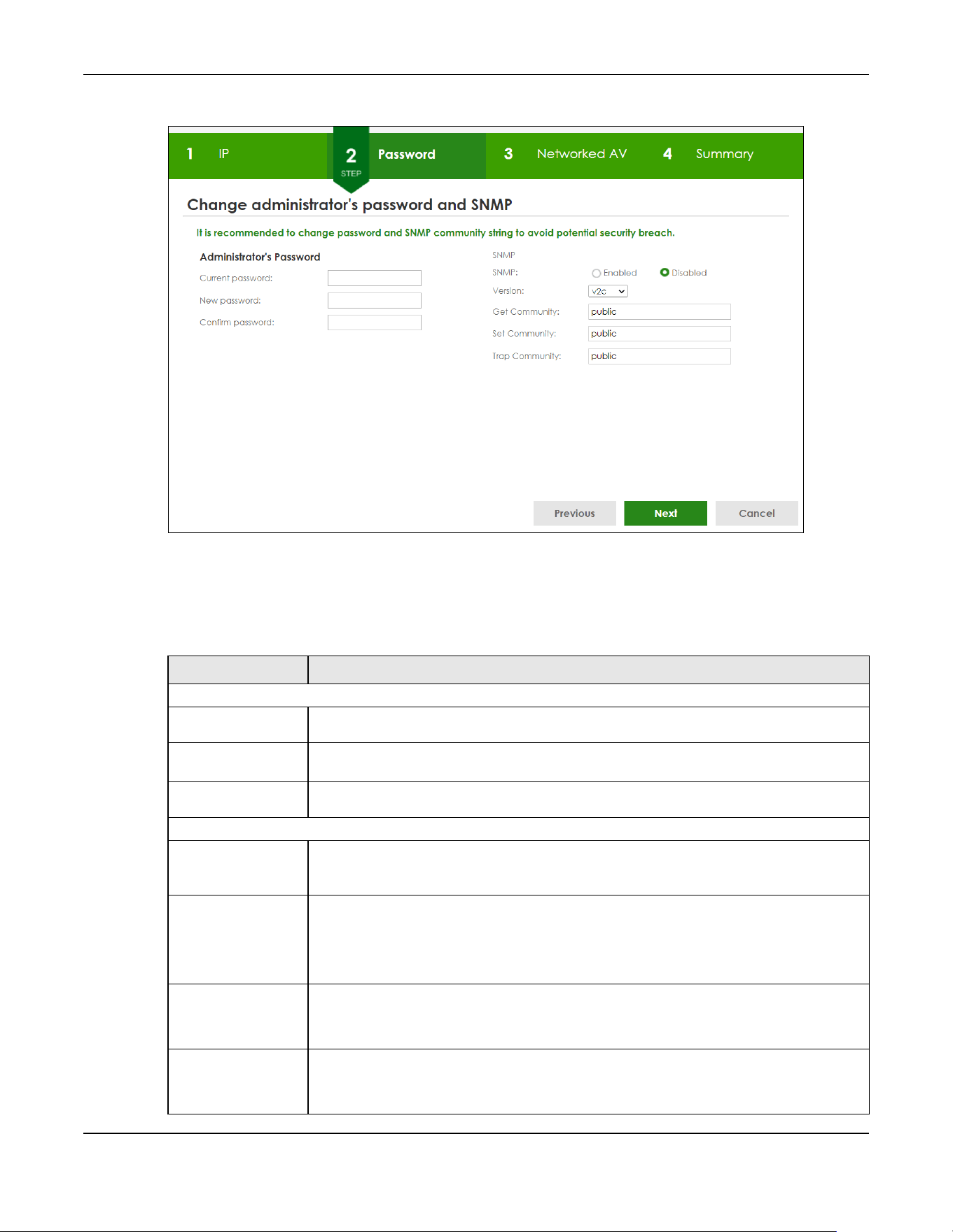
Chapter 4 Web Configurator
XGS2220 Series User’s Guide
69
Figure 48 Wizard > Basic Settings > Step 2 Password
Note: The input string of any field in this screen should not contain [ ? ], [ | ], [ ' ], [ " ], or [ , ]. In
the Password fields, [ space ] is also not allowed.
Each field is described in the following table.
Table 13 Wizard > Basic Settings > Step 2 Password
LABEL DESCRIPTION
Administrator's Password
Current
password
Enter the existing system password (1234 is the default password when shipped).
New password Enter your new system password. Up to 32 printable ASCII characters are allowed for the
new password.
Confirm
password
Re-enter your new system password for confirmation.
SNMP
SNMP Select Enabled to let the Switch act as an SNMP agent, which allows a manager station to
manage and monitor the Switch through the network. Select Disabled to turn this feature
off.
Version Select the SNMP version for the Switch. The SNMP version on the Switch must match the
version on the SNMP manager. Choose SNMP version 2c (v2c), SNMP version 3 (v3) or both
(v3v2c).
Note: SNMP version 2c is backwards compatible with SNMP version 1.
Get Community Enter the Get Community string, which is the password for the incoming Get- and
GetNextrequests from the management station.
The Get Community string is only used by SNMP managers using SNMP version 2c or lower.
Set Community Enter the Set Community string, which is the password for the incoming Set- requests from
the management station.
The Set Community string is only used by SNMP managers using SNMP version 2c or lower.
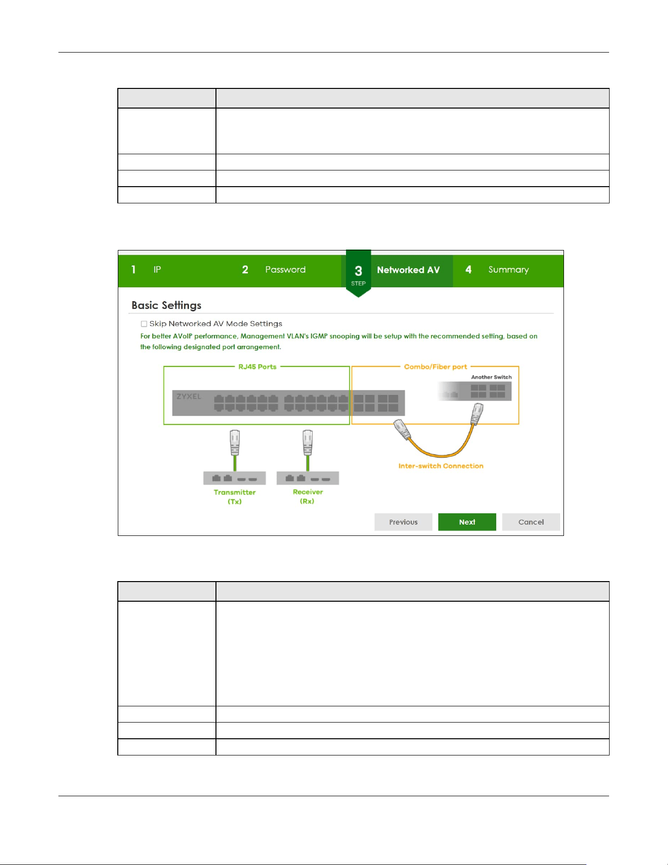
Chapter 4 Web Configurator
XGS2220 Series User’s Guide
70
After clicking Next, the Networked AV screen appears.
Figure 49 Wizard > Basic Settings > Step 3 Networked AV
Each field is described in the following table.
After clicking Next, the Summary screen appears.
Trap Community Enter the Trap Community string, which is the password sent with each trap to the SNMP
manager.
The Trap Community string is only used by SNMP managers using SNMP version 2c or lower.
Previous Click Previous to show the previous screen.
Next Click Next to show the next screen.
Cancel Click Cancel to exit this screen without saving.
Table 14 Wizard > Basic Settings > Step 3 Networked AV
LABEL DESCRIPTION
Skip Networked AV
Mode Settings
Click this option to avoid using the basic default AVoIP settings. The default AVoIP settings
can be seen in Step 4 Summary under Networked AV – Basic Settings.
Otherwise, clear the check box and follow the diagram for connecting RJ45 ports to audio
and video equipment. The Inter-switch Connection is for connecting to another switch.
Note: Use the Wizard > Advanced Settings > Step 3 Networked AV to configure
connections for non-Audio-Video equipment (for example computer, NAS)
to the RJ45 ports.
Previous Click Previous to show the previous screen.
Next Click Next to show the next screen.
Cancel Click Cancel to exit this screen without saving.
Table 13 Wizard > Basic Settings > Step 2 Password (continued)
LABEL DESCRIPTION

Chapter 4 Web Configurator
XGS2220 Series User’s Guide
71
Figure 50 Wizard > Basic Settings > Step 4 Summary
Each field is described in the following table.
Table 15 Wizard > Basic Settings > Step 4 Summary
LABEL DESCRIPTION
Setup IP
Host Name This field displays a host name.
IP Interface This field displays whether the WAN interface is using a DHCP IP address or a static IP
address.
VID This field displays the VLAN ID.
IP Address This field displays the Switch’s IP address for it to be managed over the network.
IP Subnet Mask This field displays the subnet mask that specifies the network number portion of an IP
address.
Default Gateway This field displays the IP address of the default outgoing gateway in dotted decimal
notation, for example 192.168.1.254.
DNS Server This field displays the DNS (Domain Name System) for mapping a domain name to its
corresponding IP address and so forth.
Change administrator's password and activate SNMP
New Password This field displays asterisks when a new password has been created.
SNMP This field displays whether the Switch acts as an SNMP agent.
Version This field displays the SNMP version for the Switch.
Get Community This field displays the Get Community string.
Set Community This field displays the Set Community string.
Trap Community This field displays the Trap Community string.
Networked AV – Basic Settings
Networked AV
VLAN
This field displays the VLAN ID for the AVoIP network.

Chapter 4 Web Configurator
XGS2220 Series User’s Guide
72
4.4.2 Advanced Settings
In Advanced Settings, you can set up IP or DNS, set up your password, SNMP community, configure
Networked AV service to a VLAN, select and assign port role, link aggregation (trunking), and view
finished results.
In order to set up your IP or DNS, please do the following. Click Wizard > Advanced Settings > Step 1 IP to
access this screen.
Networked AV
VLAN IP
This field displays the Switch’s IP address for it to be managed over the AVoIP network.
IGMP Snooping This field displays Active when IGMP Snooping is enabled to forward group multicast traffic
only to ports that are members of that group.
Otherwise, it displays Inactive.
IGMP Snooping
Querier
This field displays Active when the Switch is allowed to send IGMP General Query messages
to the VLANs with the multicast hosts attached.
Otherwise, it displays Inactive.
Unknown
Multicast Frame
This field displays the action to perform when the Switch receives an unknown multicast
frame. It displays Drop when the frames are discarded. It displays Flooding when the frames
are sent to all ports.
Transmitter/
Receiver
Connected Port
This field shows the Switch’s port numbers for connection to networked audio and video
equipment.
Inter-switch
Connected Port
This field shows the Switch’s port numbers for connection to another switch.
Previous Click Previous to show the previous screen.
Finish Review the information and click Finish to create the task.
Cancel Click Cancel to exit this screen without saving.
Table 15 Wizard > Basic Settings > Step 4 Summary (continued)
LABEL DESCRIPTION
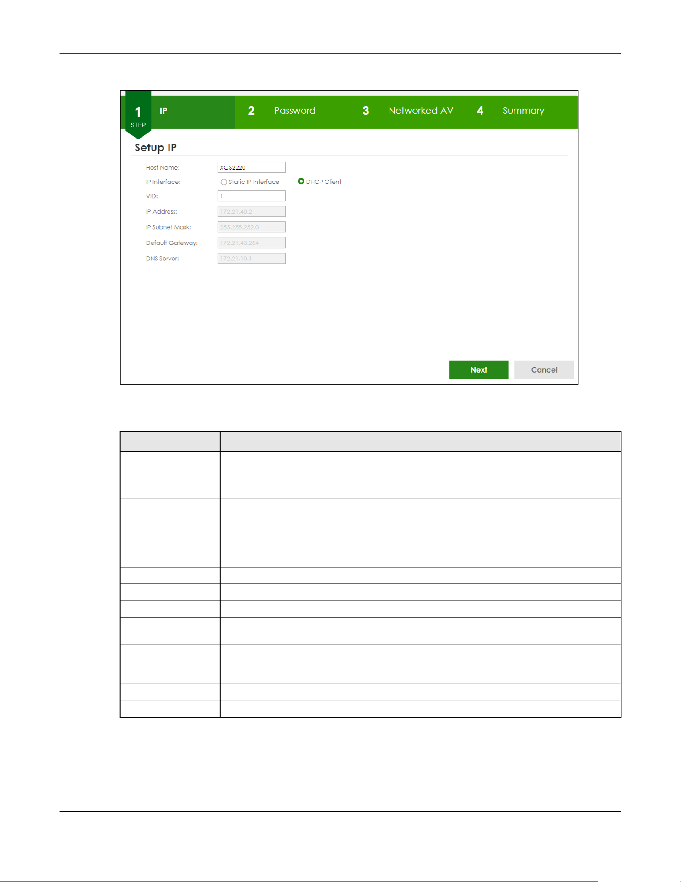
Chapter 4 Web Configurator
XGS2220 Series User’s Guide
73
Figure 51 Wizard > Advanced Settings > Step 1 IP
Each field is described in the following table.
After clicking Next, the Password screen appears.
Table 16 Wizard > Advanced Settings > Step 1 IP
LABEL DESCRIPTION
Host Name This field displays a host name.
You can enter a new host name here. Up to 64 printable ASCII characters are allowed
except [ ? ], [ | ], [ ' ], [ " ], or [ , ].
IP Interface Select DHCP Client if the Switch is connected to a router with the DHCP server enabled. You
then need to check the router for the IP address assigned to the Switch in order to access
the Switch’s Web Configurator again.
Select Static IP Interface when the Switch is NOT connected to a router or you want to
assign it a fixed IP address.
VID This field displays the VLAN ID.
IP Address The Switch needs an IP address for it to be managed over the network.
IP Subnet Mask The subnet mask specifies the network number portion of an IP address.
Default Gateway Type the IP address of the default outgoing gateway in dotted decimal notation, for
example 192.168.1.254.
DNS Server DNS (Domain Name System) is for mapping a domain name to its corresponding IP address
and so forth. Enter a domain name server IP address in order to be able to use a domain
name instead of an IP address.
Next Click Next to show the next screen.
Cancel Click Cancel to exit this screen without saving.

Chapter 4 Web Configurator
XGS2220 Series User’s Guide
74
Figure 52 Wizard > Advanced Settings > Step 2 Password
Note: The input string of any field in this screen should not contain [ ? ], [ | ], [ ' ], [ " ], or [ , ]. In
the Password fields, [ space ] is also not allowed.
Each field is described in the following table.
Table 17 Wizard > Advanced Settings > Step 2 Password
LABEL DESCRIPTION
Administrator's Password
Current
password
Type the existing system password (1234 is the default password when shipped).
New password Enter your new system password. Up to 32 printable ASCII characters are allowed for the
new password.
Confirm
password
Re-enter your new system password for confirmation.
SNMP
SNMP Select Enabled to let the Switch act as an SNMP agent, which allows a manager station to
manage and monitor the Switch through the network. Select Disabled to turn this feature
off.
Version Select the SNMP version for the Switch. The SNMP version on the Switch must match the
version on the SNMP manager. Choose SNMP version 2c (v2c), SNMP version 3 (v3) or both
(v3v2c).
Note: SNMP version 2c is backwards compatible with SNMP version 1.
Get Community Enter the Get Community string, which is the password for the incoming Get- and
GetNextrequests from the management station.
The Get Community string is only used by SNMP managers using SNMP version 2c or lower.
Set Community Enter the Set Community string, which is the password for the incoming Set- requests from
the management station.
The Set Community string is only used by SNMP managers using SNMP version 2c or lower.

Chapter 4 Web Configurator
XGS2220 Series User’s Guide
75
After clicking Next, the Networked AV screen appears.
Figure 53 Wizard > Advanced Settings > Step 3 Networked AV
Each field is described in the following table.
Trap Community Enter the Trap Community string, which is the password sent with each trap to the SNMP
manager.
The Trap Community string is only used by SNMP managers using SNMP version 2c or lower.
Previous Click Previous to show the previous screen.
Next Click Next to show the next screen.
Cancel Click Cancel to exit this screen without saving.
Table 18 Wizard > Advanced Settings > Step 3 Networked AV
LABEL DESCRIPTION
Allocate networked AV service to a VLAN
Networked AV
VLAN
Enter a number between 1 and 4094 to create a VLAN for the AVoIP network (see Figure 4
on page 35 for details on an AVoIP network).
IP Address
(Optional)
You must enter a different VLAN ID in the previous field (Networked AV VLAN) to be able to
assign another IP address for the Switch to be managed over the AVoIP network.
IP Subnet Mask
(Optional)
You must enter a different VLAN ID in the Networked AV VLAN field to be able to assign
another subnet mask that specifies the network number portion of an IP address.
Select Ports and Assign a Port Role
Table 17 Wizard > Advanced Settings > Step 2 Password (continued)
LABEL DESCRIPTION

Chapter 4 Web Configurator
XGS2220 Series User’s Guide
76
After clicking Next, the Summary screen appears.
Figure 54 Wizard > Advanced Settings > Step 4 Summary
Each field is described in the following table.
Select all ports After you create a VLAN, select the ports to be assigned to the Networked AV VLAN.
Select all ports to assign the same role to all ports.
You can select a port by clicking it. Then click any of the following:
Click Tx/Rx to assign the ports for connecting to audio and video equipment.
Click Inter-switch to assign the ports for connecting to other switches or gateway.
Click Management to assign the ports for connecting to non-Audio-Video equipment (for
example, computer and NAS) if your Networked AV VLAN is different from management
VLAN.
Link aggregate Select this option to aggregate multiple port bandwidth if you are connecting to another
switch. Link aggregation (trunking) is the grouping of physical ports into one logical higher-
capacity link.
Previous Click Previous to show the previous screen.
Next Click Next to show the next screen.
Cancel Click Cancel to exit this screen without saving.
Table 19 Wizard > Advanced Settings > Step 4 Summary
LABEL DESCRIPTION
Setup IP
Host Name This field displays a host name.
Table 18 Wizard > Advanced Settings > Step 3 Networked AV (continued)
LABEL DESCRIPTION

Chapter 4 Web Configurator
XGS2220 Series User’s Guide
77
4.5 Wizard
The Setup Wizard contains the following parts:
IP Interface This field displays whether the WAN interface is using a DHCP IP address or a static IP
address.
VID This field displays the VLAN ID.
IP Address This field displays the Switches’ IP address for it to be managed over the network.
IP Subnet Mask This field displays the subnet mask that specifies the network number portion of an IP
address.
Default Gateway This field displays the IP address of the default outgoing gateway in dotted decimal
notation, for example 192.168.1.254.
DNS Server This field displays the DNS (Domain Name System) for mapping a domain name to its
corresponding IP address and so forth.
Change administrator's password and activate SNMP
New Password This field displays asterisks when a new password has been created.
SNMP This field displays whether the Switch acts as an SNMP agent.
Version This field displays the SNMP version for the Switch.
Get Community This field displays the Get Community string.
Set Community This field displays the Set Community string.
Trap Community This field displays the Trap Community string.
Networked AV – Advanced Settings
Networked AV
VLAN
This field displays the VLAN ID for the AVoIP network.
Networked AV
VLAN IP
This field displays the corresponding VLAN ID’s IP address for the AVoIP network.
IGMP Snooping This field displays Active when IGMP Snooping is enabled to forward group multicast traffic
only to ports that are members of that group.
Otherwise, it displays Inactive.
IGMP Snooping
Querier
This field displays Active when the Switch is allowed to send IGMP General Query messages
to the VLANs with the multicast hosts attached.
Otherwise, it displays Inactive.
Unknown
Multicast Frame
This field displays the action to perform when the Switch receives an unknown multicast
frame. It displays Drop when the frames are discarded. It displays Flooding when the frames
are sent to all ports.
Transmitter/
Receiver
Connected Port
This field shows the Switches’ port numbers for connection to networked audio and video
equipment.
Inter-switch
Connected Port
(Link
Aggregation)
This field shows the Switches’ port numbers for connection to another switch.
Previous Click Previous to show the previous screen.
Finish Review the information and click Finish to create the task.
Cancel Click Cancel to exit this screen without saving.
Table 19 Wizard > Advanced Settings > Step 4 Summary (continued)
LABEL DESCRIPTION
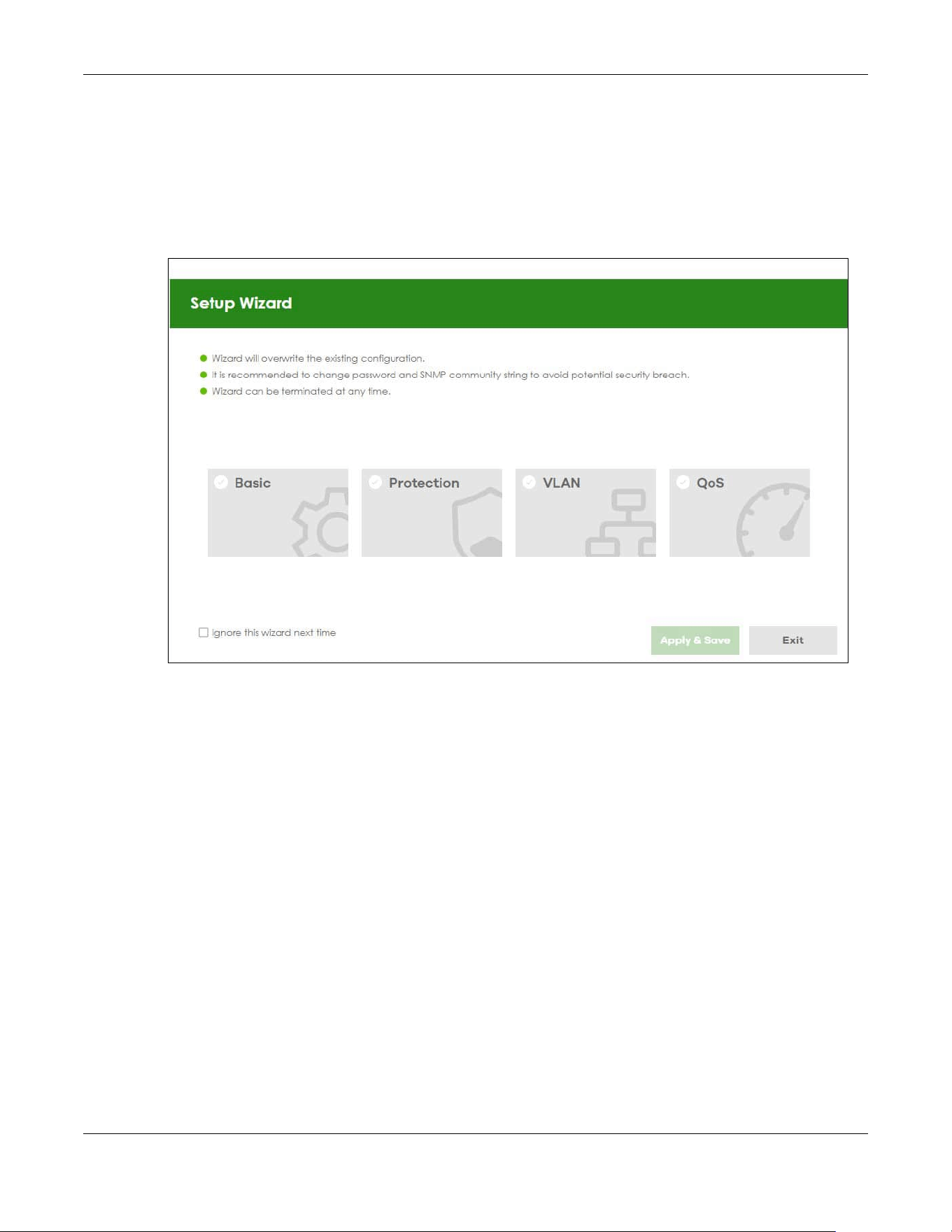
Chapter 4 Web Configurator
XGS2220 Series User’s Guide
78
• Basic – to configure the Switch IP address, DNS server, system password, SNMP community and link
aggregation (trunking).
• Protection – to enable loop guard and broadcast storm control on the Switch and its ports.
• VLAN
– to create a static VLAN, assign ports to the VLAN and set the ports to tag or untag outgoing
frames.
• QoS – to determine a port’s IEEE 802.1p priority level for QoS.
Figure 55 Setup Wizard
4.5.1 Basic
In Basic, you can set up IP/DNS, set up your password, SNMP community, link aggregation, and view
finished results.
In order to set up your IP/DNS, please do the following. Click Wizard > Basic > Step 1 IP to access this
screen.
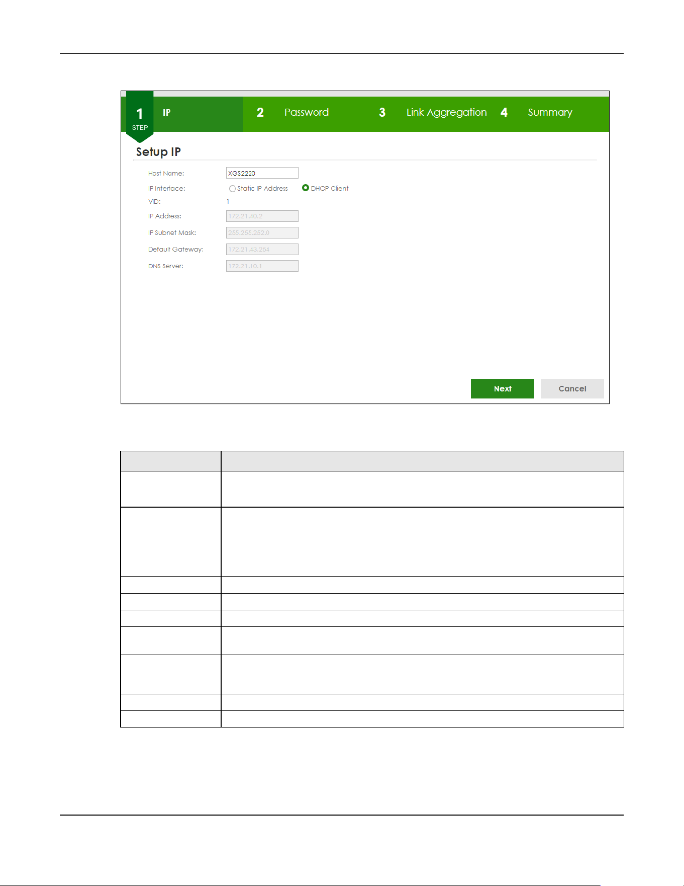
Chapter 4 Web Configurator
XGS2220 Series User’s Guide
79
Figure 56 Wizard > Basic > Step 1 IP
Each field is described in the following table.
After clicking Next, the Password screen appears.
Table 20 Wizard > Basic > Step 1 IP
LABEL DESCRIPTION
Host Name This field displays a host name. Enter a string to set a new host name.
The host name should not contain [ ? ], [ | ], [ ' ], [ " ], or [ , ].
IP Interface Select DHCP Client if the Switch is connected to a router with the DHCP server enabled. You
then need to check the router for the IP address assigned to the Switch in order to access
the Switch’s Web Configurator again.
Select Static IP Address when the Switch is NOT connected to a router or you want to assign
it a fixed IP address.
VID This field displays the VLAN ID.
IP Address The Switch needs an IP address for it to be managed over the network.
IP Subnet Mask The subnet mask specifies the network number portion of an IP address.
Default Gateway Type the IP address of the default outgoing gateway in dotted decimal notation, for
example 192.168.1.254.
DNS Server DNS (Domain Name System) is for mapping a domain name to its corresponding IP address
and so forth. Enter a domain name server IP address in order to be able to use a domain
name instead of an IP address.
Next Click Next to show the next screen.
Cancel Click Cancel to exit this screen without saving.
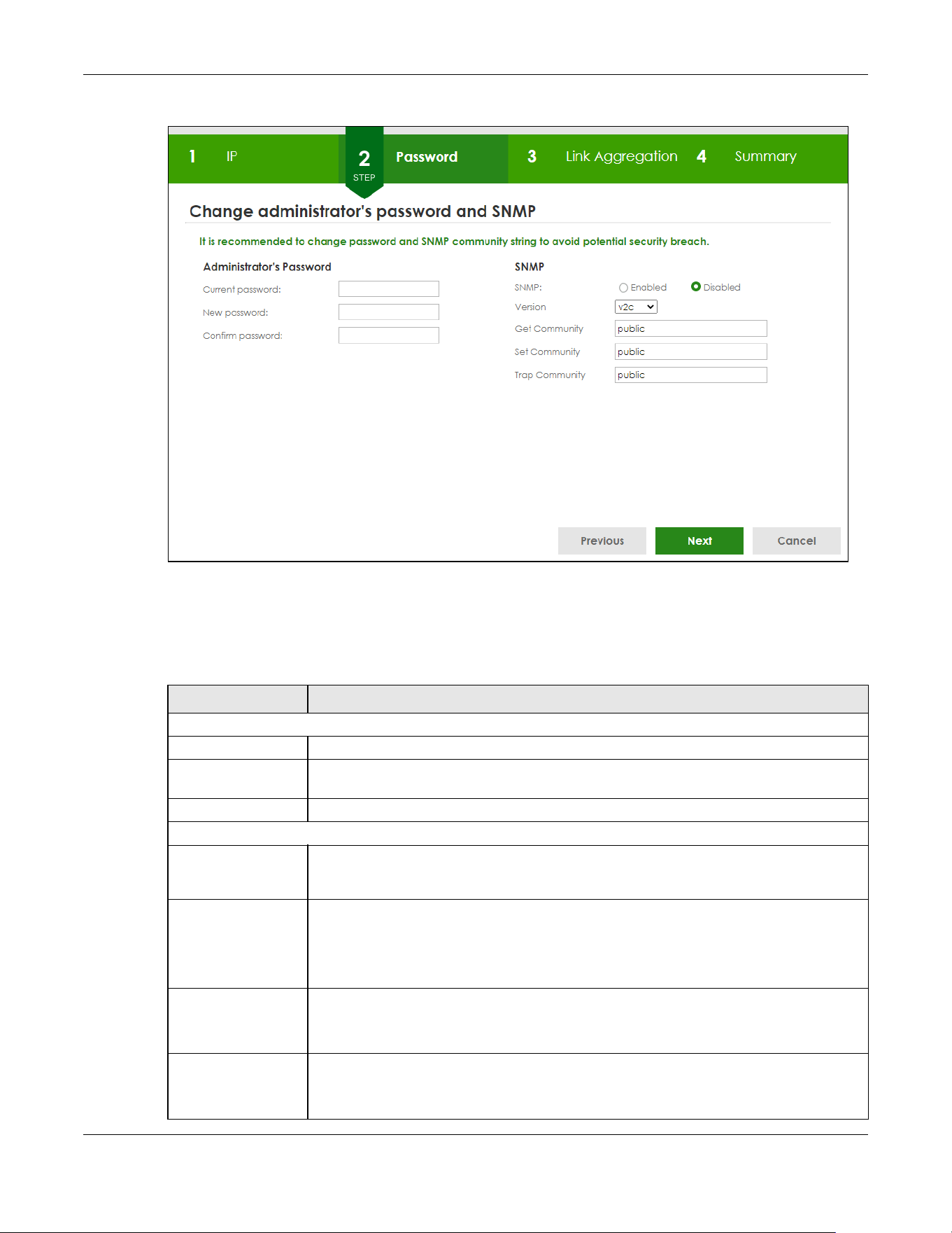
Chapter 4 Web Configurator
XGS2220 Series User’s Guide
80
Figure 57 Wizard > Basic > Step 2 Password
Note: The input string of any field in this screen should not contain [ ? ], [ | ], [ ' ], [ " ], or [ , ].
In the Password fields, [ space ] is also not allowed.
Each field is described in the following table.
Table 21 Wizard > Basic > Step 2 Password
LABEL DESCRIPTION
Administrator's Password
Current password Type the existing system password (1234 is the default password when shipped).
New password Enter your new system password. Up to 32 printable ASCII characters are allowed for the
new password.
Confirm password Retype your new system password for confirmation.
SNMP
SNMP Select Enabled to let the Switch act as an SNMP agent, which allows a manager station to
manage and monitor the Switch through the network. Select Disabled to turn this feature
off.
Version Select the SNMP version for the Switch. The SNMP version on the Switch must match the
version on the SNMP manager. Choose SNMP version 2c (v2c), SNMP version 3 (v3) or both
(v3v2c).
Note: SNMP version 2c is backwards compatible with SNMP version 1.
Get Community Enter the Get Community string, which is the password for the incoming Get- and
GetNextrequests from the management station.
The Get Community string is only used by SNMP managers using SNMP version 2c or lower.
Set Community Enter the Set Community string, which is the password for the incoming Set- requests from
the management station.
The Set Community string is only used by SNMP managers using SNMP version 2c or lower.

Chapter 4 Web Configurator
XGS2220 Series User’s Guide
81
After clicking Next, the Link Aggregation screen appears.
Figure 58 Wizard > Basic > Step 3 Link Aggregation
Each field is described in the following table.
After clicking Next, the Summary screen appears.
Trap Community Enter the Trap Community string, which is the password sent with each trap to the SNMP
manager.
The Trap Community string is only used by SNMP managers using SNMP version 2c or lower.
Previous Click Previous to show the previous screen.
Next Click Next to show the next screen.
Cancel Click Cancel to exit this screen without saving.
Table 22 Wizard > Basic > Step 3 Link Aggregation
LABEL DESCRIPTION
Link Aggregation
T1-Tx Click the arrows to add or delete icons located on the left to desired preference.
Select Static if the ports are configured as static members of a trunk group.
Select LACP if the ports are configured to join a trunk group through LACP.
Previous Click Previous to show the previous screen.
Next Click Next to show the next screen.
Cancel Click Cancel to exit this screen without saving.
Table 21 Wizard > Basic > Step 2 Password (continued)
LABEL DESCRIPTION

XGS2220 Series User’s Guide
82
Figure 59 Wizard > Basic > Step 4 Summary
Each field is described in the following table.
Table 23 Wizard > Basic > Step 4 Summary
LABEL DESCRIPTION
Setup IP
Host Name This field displays a host name.
IP Interface This field displays whether the WAN interface is using a DHCP IP address or a static IP
address.
VID This field displays the VLAN ID.
IP Address The Switch needs an IP address for it to be managed over the network.
IP Subnet Mask The subnet mask specifies the network number portion of an IP address.
Default Gateway Type the IP address of the default outgoing gateway in dotted decimal notation, for
example 192.168.1.254.
DNS Server DNS (Domain Name System) is for mapping a domain name to its corresponding IP address
and vice versa. Enter a domain name server IP address in order to be able to use a domain
name instead of an IP address.
Change administrator's password and activate SNMP
New Password This field displays asterisks when a new password has been created.
SNMP This field displays whether the Switch acts as an SNMP agent.
Version This field displays the SNMP version for the Switch.
Get Community This field displays the Get Community string.
Set Community This field displays the Set Community string.
Trap Community This field displays the Trap Community string.
Link Aggregation
Group This field displays the group number.
Type This field displays Static or LACP of this group.
Member This field displays the members of this group.

Chapter 4 Web Configurator
XGS2220 Series User’s Guide
83
4.5.2 Protection
In Protection, you can set up loop guard and broadcast storm control.
In order to set up loop guard, please do the following. Click Wizard > Protection > Step 1 Loop Guard to
access this screen.
Figure 60 Wizard > Protection > Step 1 Loop Guard
Each field is described in the following table.
After clicking Next, the Broadcast Storm Control screen appears.
Previous Click Previous to show the previous screen.
Finish Review the information and click Finish to create the task.
Cancel Click Cancel to exit this screen without saving.
Table 23 Wizard > Basic > Step 4 Summary (continued)
LABEL DESCRIPTION
Table 24 Wizard > Protection > Step 1 Loop Guard
LABEL DESCRIPTION
Loop Guard
Select all ports Select all ports to enable the loop guard feature on all ports.
You can select a port by clicking it.
Next Click Next to show the next screen.
Cancel Click Cancel to exit this screen without saving.

Chapter 4 Web Configurator
XGS2220 Series User’s Guide
84
Figure 61 Wizard > Protection > Step 2 Broadcast Storm Control
Each field is described in the following table.
After clicking Next, the Summary screen appears.
Table 25 Wizard > Protection > Step 2 Broadcast Storm Control
LABEL DESCRIPTION
Broadcast Storm Control
Select all ports Select all ports to apply settings on all ports.
You can select a port by clicking it.
Broadcast pkt/s Specify how many broadcast packets the port receives per second.
Previous Click Previous to show the previous screen.
Next Click Next to show the next screen.
Cancel Click Cancel to exit this screen without saving.
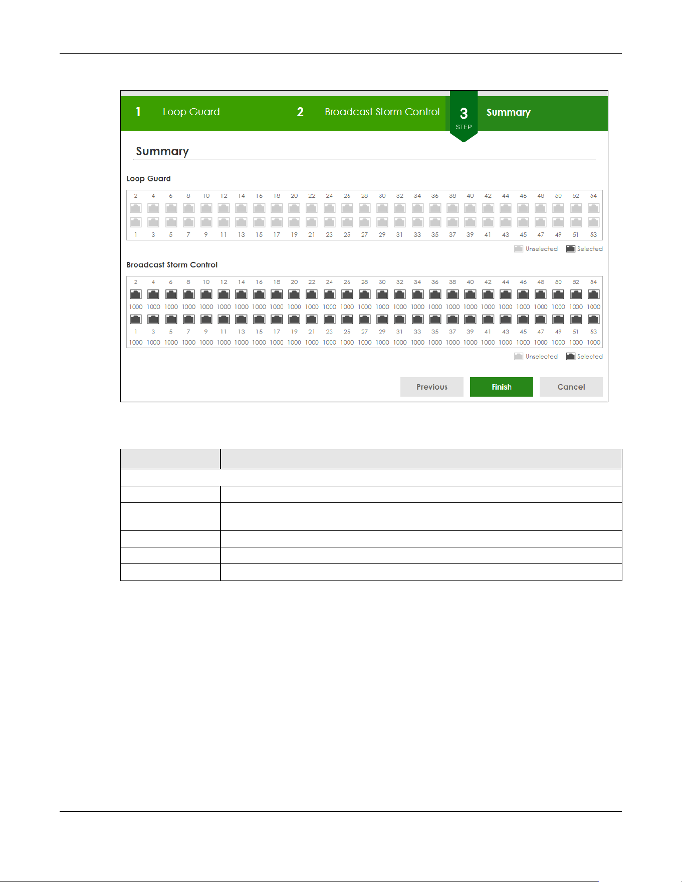
Chapter 4 Web Configurator
XGS2220 Series User’s Guide
85
Figure 62 Wizard > Protection > Step 3 Summary
Each field is described in the following table.
4.5.3 VLAN
In VLAN, you can create VLAN, and tag VLAN settings.
Click Wizard > VLAN > VLAN Setting to access this screen.
Table 26 Wizard > Protection > Step 3 Summary
LABEL DESCRIPTION
Summary
Loop Guard If the loop guard feature is enabled on a port, the Switch will prevent loops on this port.
Broadcast Storm
Control
If the broadcast storm control feature is enabled on a port, the number of broadcast
packets the Switch receives per second will be limited on this port.
Previous Click Previous to show the previous screen.
Finish Review the information and click Finish to create the task.
Cancel Click Cancel to exit this screen without saving.
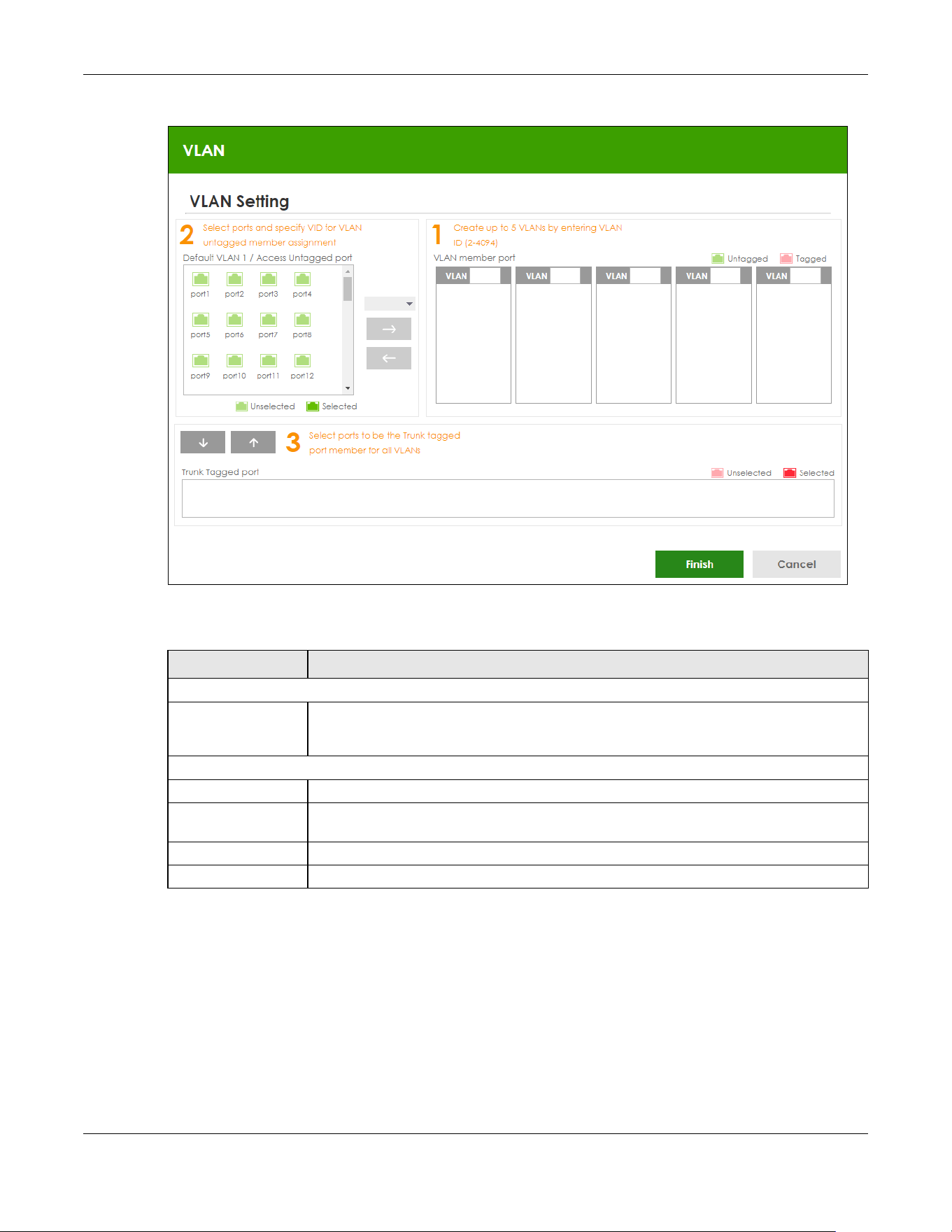
Chapter 4 Web Configurator
XGS2220 Series User’s Guide
86
Figure 63 Wizard > VLAN > VLAN Setting
Each field is described in the following table.
4.5.4 QoS
In QoS, you can create QoS settings.
In order to create QoS settings, please do the following. Click Wizard > QoS > QoS Setting to access this
screen.
Table 27 Wizard > VLAN > VLAN Setting
LABEL DESCRIPTION
VLAN Setting
Default VLAN 1 /
Access Untagged
port
After you create a VLAN and select the VLAN ID from the drop-down list box, select ports
and use the right arrow to add them as the untagged ports to a VLAN group.
VLAN member port
VLAN Type a number between 2 and 4094 to create a VLAN.
Trunk Tagged port Select ports and use the downward arrow to add them as the tagged ports to the VLAN
groups you created.
Finish Review the information and click Finish to create the task.
Cancel Click Cancel to exit this screen without saving.

Chapter 4 Web Configurator
XGS2220 Series User’s Guide
87
Figure 64 Wizard > QoS > QoS Setting
Each field is described in the following table.
4.6 Web Configurator Layout
The DASHBOARD screen is the first screen that displays when you access the Web Configurator.
Table 28 Wizard > QoS > QoS Setting
LABEL DESCRIPTION
QoS Setting
Select all ports Select all ports to apply settings on all ports.
You can select a port by clicking it.
High Select ports and click the High button, so they will have high priority.
The port’s IEEE 802.1p priority level will be set to 5. Use the PORT > Port Setup screen to adjust
the value.
Medium Select ports and click the Medium button and, so they will have medium priority.
The port’s IEEE 802.1p priority level will be set to 3. Use the PORT > Port Setup screen to adjust
the value.
Low Select ports and click the Low button, so they will have low priority.
The port’s IEEE 802.1p priority level will be set to 1. Use the PORT > Port Setup screen to adjust
the value.
Finish Review the information and click Finish to create the task.
Cancel Click Cancel to exit this screen without saving.
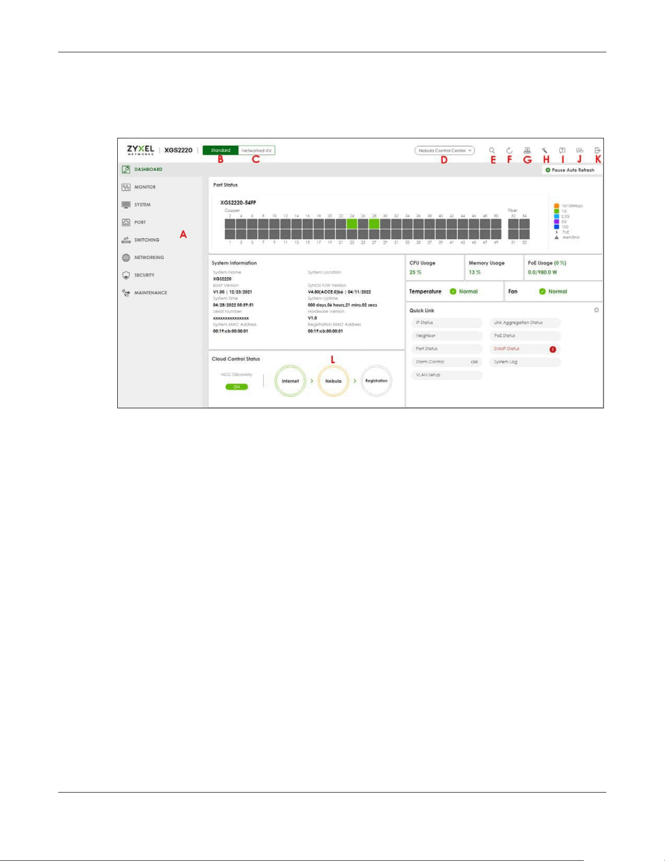
Chapter 4 Web Configurator
XGS2220 Series User’s Guide
88
This guide uses the XGS2220-54FP screens as examples. The screens may vary slightly for different models.
The following figure shows the navigating components of a Web Configurator screen.
Figure 65 Web Configurator Layout
A
– Click the menu items to open sub-menu links, and then click on a sub-menu link to open the screen
in the main window.
B, C, D, E, F, G, H, I, J, K
– These are quick links which allow you to perform certain tasks no matter which
screen you are currently working in.
B, C
– Click this icon to switch between the Web Configurator’s Standard or Networked AV mode.
D
– Click this icon to go to the NCC (Nebula Control Center) portal website.
E – Click this icon to search for specific configurations or status you are looking for. Enter the keywords
and click the result link. This will direct you to the specific configuration or status page.
F – Click this icon to update the information in the screen you are currently viewing.
G
– Click this icon to save your configuration into the Switch’s non-volatile memory. Non-volatile memory
is the configuration of your Switch that stays the same even if the Switch’s power is turned off.
H
– Click this icon to display the Setup Wizard that contains the Basic, Protection, VLAN, and QoS setup
screens.
I
– Click this icon to display web help pages. The help pages provide descriptions for all of the
configuration screens.
J
– Click this icon to go to the Zyxel Community Biz Forum.
K
– Click this icon to log out of the Web Configurator.

Chapter 4 Web Configurator
XGS2220 Series User’s Guide
89
L – This displays the Nebula Cloud Control Status. The ON/OFF switch displays if NCC Discovery is
enabled. If a status circle turns Orange, it means the Switch is unable to connect to NCC. Hover the
mouse over the status circle to check the diagnostic message. You can also click the ON/OFF switch to
go to the SYSTEM > Cloud Management screen and check the diagnostic messages. See Section Table
50 on page 159 for more information.
In the navigation panel, click a main link to reveal a list of sub-menu links.
The following table describes the links in the navigation panel. The navigation panel varies depending
on the product model you use.
Table 29 Navigation Panel Links (Standard Mode)
LINK DESCRIPTION
DASHBOARD This link takes you to the main dashboard screen that displays general system and device infor-
mation.
MONITOR
ARP Table This link takes you to a screen that displays the current ARP table of the Switch. You can view the
IP and MAC address mapping, VLAN ID, ARP aging time, and ARP entry type of a device
attached to a port.
IP Table This link takes you to a screen where you can view the IP address and VLAN ID of a device
attached to a port.
IPv6 Neighbor
Table
This link takes you to a screen where you can view the Switch’s IPv6 neighbor table.
MAC Table This link takes you to a screen where you can view the MAC address and VLAN ID of a device
attach to a port. You can also view what kind of MAC address it is.
Neighbor This link takes you to a screen where you can view neighbor devices (including non-Zyxel
devices) connected to the Switch.
Path MTU Table This link takes you to a screen where you can view the IPv6 path MTU information on the Switch.
Port Status This link takes you to a screen where you can view the port statistics.
Routing Table Click the link to unfold the following sub-link menu.
IPv4
Routing
Table
This link takes you to a screen where you can view the IPv4 routing table for routing information
including IP interface and hop count to certain network destinations.
IPv6
Routing
Table
This link takes you to a screen where you can view the IPv6 routing table for routing information
including IP interface and hop count to certain network destinations.
System Infor-
mation
This link takes you to a screen that displays general system information.
System Log This link takes you to a screen where you can view the system log including fail log and system
status.
SYSTEM
Cloud Man-
agement
This link takes you to a screen where you can enable or disable the Nebula Control Center (NCC)
Discovery feature and view the NCC connection status. If Nebula Control Center (NCC) Discov-
ery is enabled, you can have the Switch search for the NCC (Nebula Control Center). The screen
also displays a QR code containing the Switch’s serial number and MAC address for handy regis-
tration of the Switch at NCC.
General Setup This link takes you to a screen where you can configure general identification information about
the Switch.
Hardware
Monitor Setup
This link takes you to a screen where you can configure hardware monitor related features such
as SFP Detect.
Interface Setup This link takes you to a screen where you can configure settings for individual interface type and
ID.

Chapter 4 Web Configurator
XGS2220 Series User’s Guide
90
IP Setup This link takes you to a screen where you can configure the DHCP client, and a static IP address
(IP address and subnet mask).
IPv6 Click the link to unfold the following sub-link menu.
IPv6 Status This link takes you to a screen where you can view the IPv6 table and DNS server.
IPv6 Global
Setup
This link takes you to a screen where you can configure the global IPv6 settings.
IPv6
Interface
Setup
This link takes you to a screen where you can view and configure IPv6 interfaces.
IPv6
Addressing
This link takes you to a screen where you can view and configure IPv6 link-local and global
addresses.
IPv6
Neighbor
Discovery
This link takes you to a screen where you can view and configure neighbor discovery settings on
each interface.
IPv6
Neighbor
Setup
configure static IPv6 neighbor entries in the Switch’s IPv6 neighbor table.
DHCPv6
Client
Setup
This link takes you to a screen where you can configure the Switch’s DHCP settings when it is act-
ing as a DHCPv6 client.
Logins This link takes you to a screen where you can change the system login password, as well as con-
figure up to four login details.
SNMP This link takes you to screens where you can specify the SNMP version and community (password)
values, configure where to send SNMP traps from the Switch, enable loopguard/errdisable/poe/
linkup/linkdown/lldp/transceiver-ddm/storm-control on the Switch, specify the types of SNMP
traps that should be sent to each SNMP manager, and add/edit user information.
Stacking This link takes you to screens where you can view the stacking status in the stacking system,
enable stacking on the Switch, and configure stacking details.
Switch Setup This link takes you to a screen where you can set up global Switch parameters such as VLAN type.
Syslog Setup This link takes you to a screen where you can configure the Switch’s system logging settings and
configure a list of external syslog servers.
Time Range This link takes you to a screen where you can configure time range for time-oriented features like
Classifier.
PORT
Auto PD
Recovery
This link takes you to a screen where you can enable and configure Auto PD Recovery on the
Switch.
Flex Link This screen takes you to a screen where you can view configure backup links in the Data Link
layer.
Green Ethernet This link takes you to a screen where you can configure the Switch to reduce port power con-
sumption.
Link Aggrega-
tion
This link takes you to a screen where you can logically aggregate physical links to form one logi-
cal, higher-bandwidth link.
LLDP Click the link to unfold the following sub-link menu.
LLDP This link takes you to screens where you can view LLDP information and configure LLDP and TLV
settings.
LLDP MED This link takes you to screens where you can configure LLDP-MED parameters.
OAM This link takes you to screens where you can enable Ethernet OAM on the Switch, view the config-
uration of ports on which Ethernet OAM is enabled and perform remote-loopback tests.
Table 29 Navigation Panel Links (Standard Mode) (continued)
LINK DESCRIPTION

Chapter 4 Web Configurator
XGS2220 Series User’s Guide
91
PoE Setup For PoE models.
This link takes you to a screen where you can set priorities, PoE power-up settings and schedule so
that the Switch is able to reserve and allocate power to certain PDs.
Port Setup This link takes you to a screen where you can configure settings for individual Switch ports.
ZULD This link takes you to screens where you can enable ZULD on a port and configure related set-
tings.
SWITCHING
Layer 2 Proto-
col Tunneling
This link takes you to a screen where you can configure L2PT (Layer 2 Protocol Tunneling) settings
on the Switch.
Loop Guard This link takes you to a screen where you can configure protection against network loops that
occur on the edge of your network.
MAC Pinning This link takes you to a screen where you can set specific ports to have priority over other ports in
MAC address learning.
Mirroring Click the link to unfold the following sub-link menu.
Mirroring This link take you to a screen where you can copy traffic from one port or ports to another port in
order to examine the traffic from the first port without interference.
Multicast Click the link to unfold the following sub-link menu.
IPv4
Multicast
This link takes you to screen where you can configure various IPv4 multicast features, IGMP snoop-
ing, filtering and create multicast VLANs.
IPv6
Multicast
This link takes you to screen where you can configure various IPv6 multicast features, MLD snoop-
ing-proxy, filtering and create multicast VLANs.
MVR This link takes you to screens where you can create multicast VLANs and select the receiver ports
and a source port for each multicast VLAN.
Static
Multicast
Forwarding
By MAC
This link takes you to a screen where you can configure static multicast MAC addresses for port(s).
These static multicast MAC addresses do not age out.
Static
Multicast
Forwarding
By IP
This link takes you to a screen where you can configure static multicast IP addresses for port(s).
These static multicast IP addresses do not age out.
PPPoE Interme-
diate Agent
This link takes you to screens where you can enable PPPoE (Point-to-Point Protocol over Ethernet)
Intermediate Agent and configure per-port, per-port-per-VLAN settings.
QoS Click the link to unfold the following sub-link menu.
Diffserv This link takes you to screens where you can enable DiffServ, configure marking rules and set
DSCP-to-IEEE802.1p mappings.
Queuing
Method
This link takes you to a screen where you can set priorities for the queues of the Switch. This distrib-
utes bandwidth across the different traffic queues.
Priority
Queue
This link takes you to a screen where you can set priority tags for different traffic types and specify
the priority levels.
Bandwidth
Control
This link takes you to a screen where you can cap the maximum bandwidth allowed on a port.
sFlow This link takes you to screens where you can configure sFlow settings on the Switch.
Spanning Tree
Protocol
Click the link to unfold the following sub-link menu.
Spanning
Tree
Protocol
Status
This link takes you to a screen where you can view the STP status in the different STP modes (RSTP,
MRSTP or MSTP) you can configure on the Switch.
Table 29 Navigation Panel Links (Standard Mode) (continued)
LINK DESCRIPTION

Chapter 4 Web Configurator
XGS2220 Series User’s Guide
92
Spanning
Tree Setup
This link takes you to a screen where you can activate one of the STP modes (RSTP, MRSTP or
MSTP) on the Switch.
RSTP This link takes you to a screen where you can configure the RSTP (Rapid Spanning Tree Protocol)
settings on the Switch.
MRSTP This link takes you to a screen where you can configure the MRSTP (Multiple Rapid Spanning Tree
Protocol) settings on the Switch.
MSTP This link takes you to a screen where you can configure the MSTP (Multiple Spanning Tree Proto-
col) settings on the Switch.
Static MAC Fil-
tering
This link takes you to a screen to set up static MAC filtering rules.
Static MAC For-
warding
This link takes you to a screen where you can configure static MAC addresses for a port. These
static MAC addresses do not age out.
VLAN Click the link to unfold the following sub-link menu.
VLAN
Status
This link takes you to a screen where you can view and search all VLAN groups.
VLAN Setup This link takes you to screens where you can:
• configure port-based or 802.1Q VLAN.
• view detailed port settings and status of the VLAN group.
• configure and view 802.1Q VLAN parameters for the Switch.
• configure the static VLAN settings on a port.
Subnet
Based
VLAN Setup
This link takes you to a screen where you can set up VLANs that allow you to group traffic into log-
ical VLANs based on the source IP subnet you specify.
Protocol
Based
VLAN Setup
This link takes you to a screen where you can set up VLANs that allow you to group traffic into log-
ical VLANs based on the protocol you specify.
Voice
VLAN Setup
This link takes you to a screen where you can set up VLANs that allow you to group voice traffic
with defined priority and enable the Switch port to carry the voice traffic separately from data
traffic to ensure the sound quality does NOT deteriorate.
MAC Based
VLAN Setup
This link takes you to a screen where you can set up VLANs that allow you to group untagged
packets into logical VLANs based on the source MAC address of the packet. This eliminates the
need to reconfigure the Switch when you change ports. The Switch will forward the packets
based on the source MAC address you set up previously.
Vendor ID
Based
VLAN Setup
This link takes you to screens where you can set up VLANs that allow you to group untagged
packets into logical VLANs based on the source MAC address of the packet. You can specify a
mask for the MAC address to create a MAC address filter and enter a weight to set the VLAN
rule’s priority.
VLAN Isolation This link takes you to a screen where you can block traffic between ports in a VLAN on the Switch.
VLAN Mapping This link takes you to screens where you can configure VLAN mapping settings on the Switch.
VLAN Stacking This link takes you to screens where you can activate and configure VLAN stacking.
NETWORKING
ARP Setup Click the link to unfold the following sub-link menu.
ARP
Learning
This link takes you to a screen where you can configure ARP learning mode on a per-port basis.
Static ARP This link takes you to a screen where you can create static ARP entries which do not age out.
DHCP Click the link to unfold the following sub-link menu.
DHCPv4
Relay
This link takes you to screens where you can view DHCPv4 relay status, mode, and configure
DHCPv4 relay settings.
DHCPv6
Relay
This link takes you to a screen where you can enable and configure DHCPv6 relay.
Table 29 Navigation Panel Links (Standard Mode) (continued)
LINK DESCRIPTION

Chapter 4 Web Configurator
XGS2220 Series User’s Guide
93
DHCP
Server
Guard
This link takes you to a screen where you can specify whether ports are trusted or untrusted ports
for DHCP packets.
Static Routing Click the link to unfold the following sub-link menu.
IPv4 Static
Route
This link takes you to a screen where you can configure IPv4 static routes. A static route defines
how the Switch should forward traffic by destination IP address and subnet mask.
IPv6 Static
Route
This link takes you to a screen where you can configure IPv6 static routes. A static route defines
how the Switch should forward traffic by destination IP address and prefix length.
SECURITY
AAA Click the link to unfold the following sub-link menu.
RADIUS
Server
Setup
This link takes you to a screen where you can configure your RADIUS (Remote Authentication Dial-
In User Service) server settings for authentication.
TACACS+
Server
Setup
This link takes you to a screen where you can configure your TACACS+ (Terminal Access Control-
ler Access Control System Plus) server settings for authentication.
AAA Setup This link takes you to a screen where you can configure authentication, authorization and
accounting services through external servers. The external servers can be either RADIUS or
TACACS+ (Terminal Access Controller Access Control System Plus).
Access Control Click the link to unfold the following sub-link menu.
Service
Access
Control
This link takes you to a screen where you can decide what services you may use to access the
Switch.
Remote
Managem
ent
This link takes you to a screen where you can specify a group of one or more “trusted computers”
from which an administrator may use a service to manage the Switch.
Account
Security
This link takes you to a screen where you can configure account security settings on the Switch.
ACL Click the link to unfold the following sub-link menu.
Classifier This link takes you to screens where you can configure the Switch to group packets based on the
specified criteria.
Policy Rule This link takes you to a screen where you can configure the Switch to perform special treatment
on the grouped packets.
Anti-Arpscan This link takes you to screens where you can enable anti-arpscan on the Switch and ports, and
view the port state. You can also create trusted hosts, view blocked hosts and unblock them.
BPDU Guard This link takes you to screens where you can enable BPDU guard on the Switch and ports, and
view the port state.
Storm Control This link takes you to a screen to set up broadcast filters.
Errdisable This link takes you to screens where you can view errdisable status and configure errdisable set-
tings in CPU protection, errdisable detect, and errdisable recovery.
IPv4 Source
Guard
Click the link to unfold the following sub-link menu.
IP Source
Guard
This link takes you to screens where you can configure filtering of unauthorized DHCP and ARP
packets in your network.
ARP
Inspection
This link takes you to screens where you can view ARP inspection status, and configure ARP
inspection settings on ports or VLANs. You can use ARP inspection to filter unauthorized ARP pack-
ets on the network.
IPv6 Source
Guard
Click the link to unfold the following sub-link menu.
IPv6 Static
Binding
The link takes you to screens where you can view IPv6 static binding status and manually create
IPv6 source guard static binding entries.
Table 29 Navigation Panel Links (Standard Mode) (continued)
LINK DESCRIPTION

Chapter 4 Web Configurator
XGS2220 Series User’s Guide
94
The following table describes the links in the navigation panel when the Switch is in Networked AV
mode.
IPv6 Source
Guard
The link takes you to screens where you can define policies to have IPv6 source guard forward
valid addresses and/or prefixes and allow or block data traffic from all link-local addresses, and
apply the configured IPv6 source guard policy to a port.
IPv6
Snooping
The link takes you to screens where you can set up DHCPv6 snooping policies for the binding
table and enable the policies on VLAN interfaces.
DHCPv6
Trust Setup
The link takes you to a screen where you can specify which ports are trusted for DHCPv6 snoop-
ing.
Port Authenti-
cation
Click the link to unfold the following sub-link menu.
These links take you to screens where you can configure IEEE 802.1x port authentication as well as
MAC authentication for clients communicating through the Switch.
Compound
Authentica
tion Mode
The link takes you to a screen where you can allow network access for clients that pass either IEEE
802.1x authentication or MAC authentication, or pass both IEEE 802.1x authentication and MAC
authentication.
Port Security This link takes you to a screen where you can activate MAC address learning and set the
maximum number of MAC addresses to learn on a port.
MAINTENANCE
Certificates The link takes you to a screen where you can import the Switch's CA-signed certificates.
Cluster Man-
agement
This link takes you to a screen where you can configure clustering management and view its sta-
tus.
Configuration Click the link to unfold the following sub-link menu.
Auto
Configurati
on
This link takes you to a screen where you can overwrite the running configuration stored in the
Switch’s RAM.
Configure
Clone
This link takes you to a screen where you can copy the basic and advanced settings from a
source port to a destination port or ports.
Diagnostic This link takes you to a screen where you can ping IP addresses, run traceroute, test ports and
show the location of the Switch.
Firmware
Upgrade
This link takes you to a screen to upload firmware to your Switch.
Reboot System This link takes you to a screen to reboot the Switch without turning the power off.
Tech-Support This link takes you to a screen where you can download related log reports for issue analysis. Log
reports include CPU history and utilization, crash and memory.
Table 30 Navigation Panel Links (Networked AV Mode)
LINK DESCRIPTION
SUMMARY This screen displays the Switch’s front panel port status, connected ports, used power, Nebula
Cloud Control status, and Networked AV status.
MONITOR
System
Information
This link takes you to a screen that displays general system information.
SYSTEM
General Setup This link takes you to a screen where you can configure general identification information
about the Switch.
IP Setup This screen allows you to configure the IP address and subnet mask (necessary for Switch
management) and set up to 64 IP routing domains.
Table 29 Navigation Panel Links (Standard Mode) (continued)
LINK DESCRIPTION

Chapter 4 Web Configurator
XGS2220 Series User’s Guide
95
4.6.1 Tables and Lists
The Web Configurator tables and lists provide several options for how to work with their entries.
Logins This link takes you to a screen where you can change the system login password, as well as
configure up to four login details.
SNMP This link takes you to screens where you can specify the SNMP version and community
(password) values, configure where to send SNMP traps from the Switch, enable loopguard/
errdisable/poe/linkup/linkdown/lldp/transceiver-ddm/storm-control on the Switch, specify the
types of SNMP traps that should be sent to each SNMP manager, and add/edit user
information.
PORT
Link Aggregation This link takes you to screens where you can logically aggregate physical links to form one
logical, higher-bandwidth link.
PoE Setup For PoE models.
This link takes you to a screen where you can set priorities, PoE power-up settings and schedule
so that the Switch is able to reserve and allocate power to certain PDs.
Port Setup This screen allows you to configure settings for individual Switch ports.
SWITCHING
Mirroring This link takes you to screens where you can copy traffic from one port or ports to another port
in order that you can examine the traffic from the first port without interference.
Multicast This link takes you to screens where you can view multicast group information, configure various
multicast features like IGMP snooping and filtering profile, and create multicast VLANs.
VLAN This link takes you to screens where you can view and search all static VLAN groups, view
detailed port settings and status of the static VLAN group, configure a static VLAN for the
Switch, and configure the static VLAN (IEEE 802.1Q) settings on a port.
SECURITY
Access Control
Service
Access
Control
This link takes you to a screen where you can decide what services you may use to access the
Switch.
Remote
Management
This link takes you to a screen where you can specify a group of one or more “trusted
computers” from which an administrator may use a service to manage the Switch.
Storm Control This link takes you to a screen to set up broadcast filters.
MAINTENANCE
Configuration
Restore
Configuration
This link takes you to a screen where you can upload a stored device configuration file.
Backup
Configuration
This link takes you to a screen where you can save your Switch’s configurations (settings) for
later use.
Save
Configuration
This link takes you to a screen where you can save the current configuration (settings) to a
specific configuration file on the Switch.
Firmware
Upgrade
This link takes you to a screen to upload firmware to your Switch.
Reboot System This link takes you to a screen to reboot the Switch without turning the power off.
Tech-Support This link takes you to a screen where you can download related log reports for issue analysis.
Log reports include CPU history and utilization, crash and memory.
Table 30 Navigation Panel Links (Networked AV Mode) (continued)
LINK DESCRIPTION

Chapter 4 Web Configurator
XGS2220 Series User’s Guide
96
4.6.1.1 Working with Table Entries
Tables have tool icons for working with table entries as shown next. You can select one or more entries,
or select the check box in the heading row to select all entries. Use the tool icons to modify the selected
entries.
Figure 66 Working with a Table
The following table describes the most common table icons.
When viewing a list, you can click on an index number to view more details about the entry. If the list has
more than one page, click the arrow button to navigate to different pages of entries.
Figure 67 Working on a List
Table 31 Common Table Icons
LABEL DESCRIPTION
Select an entry’s check box to select a specific entry. Otherwise, select the check box in the
table heading row to select all entries.
Add/Edit Click this to create a new entry or edit a selected entry. A configuration screen where you can
add a new entry or modify the settings of the selected entry will open.
In some configuration screens, the Add/Edit button is replaced by the Edit button. This means you
can only edit the existing entries in the table.
Delete To remove entries, select the entries and click Delete.

Chapter 4 Web Configurator
XGS2220 Series User’s Guide
97
4.6.2 Change Your Password
After you log in for the first time, it is recommended you change the default administrator password.
Click SYSTEM > Logins to display the next screen.
Figure 68 Change Administrator Login Password
4.7 Save Your Configuration
When you are done modifying the settings in a screen, click Apply to save your changes back to the
run-time memory. Settings in the run-time memory are lost when the Switch’s power is turned off.
Click the Save link in the upper right of the Web Configurator to save your configuration to non-volatile
memory. Non-volatile memory refers to the Switch’s storage that remains even if the Switch’s power is
turned off.
Note: Use the Save link when you are done with a configuration session.
4.8 Switch Lockout
You could block yourself (and all others) from managing the Switch if you do one of the following:
1 Delete the management VLAN (default is VLAN 1).
2 Delete all port-based VLANs with the CPU port as a member. The “CPU port” is the management port of
the Switch.

Chapter 4 Web Configurator
XGS2220 Series User’s Guide
98
3 Filter all traffic to the CPU port.
4 Disable all ports.
5 Misconfigure the text configuration file.
6 Forget the password and/or IP address.
7 Prevent all services from accessing the Switch.
8 Change a service port number but forget it.
9 You forgot to log out of the Switch from a computer before logging in again on another computer.
Note: Be careful not to lock yourself and others out of the Switch.
4.9 Reset the Switch
If you lock yourself (and others) from the Switch or forget the administrator password, you will need to
reload the factory-default configuration file or reset the Switch back to the factory defaults.
See Section 3.1 on page 45 to see how to use the RESTORE button to restore the factory default file.
4.9.1 Reboot the Switch
Press the RESET button to reboot the Switch without turning the power off. See Section 3.3 on page 54 for
more information about the LED behavior.
4.9.2 Reload the Configuration File
Uploading the factory-default configuration file replaces the current configuration file with the factory-
default configuration file. This means that you will lose all previous configurations and the speed of the
console port will be reset to the default of 115200 bps with 8 data bit, no parity, one stop bit and flow
control set to none. The password will also be reset to “1234” and the IP address to 192.168.1.1 or DHCP-
assigned IP.
To upload the configuration file, do the following:
1 Connect to the console port using a computer with terminal emulation software.
2 Disconnect and reconnect the Switch’s power to begin a session. When you reconnect the Switch’s
power, you will see the initial screen.
3 When you see the message “Press any key to enter Debug Mode within 3 seconds ...” press
any key to enter debug mode.
4 Enter atlc after the “Enter Debug Mode” message.
5 Wait for the “Starting XMODEM upload” message before activating XMODEM upload on your
terminal.
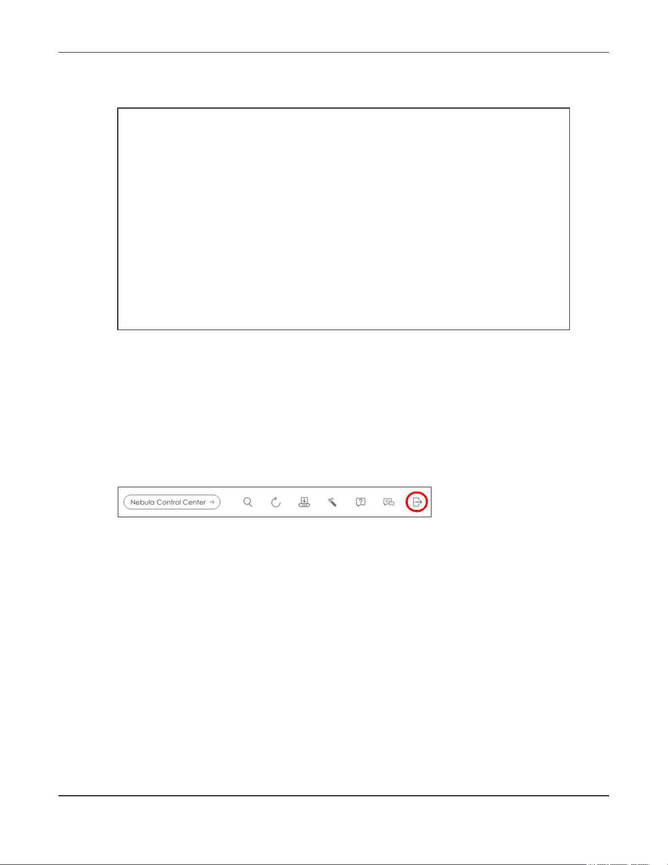
Chapter 4 Web Configurator
XGS2220 Series User’s Guide
99
6 After a configuration file upload, type atgo to restart the Switch.
Figure 69 Resetting the Switch: through the Console Port
The Switch is now reinitialized with a default configuration file including the default password of “1234”.
4.10 Log Out of the Web Configurator
Click Logout in a screen to exit the Web Configurator. You have to log in with your password again after
you log out. This is recommended after you finish a management session for security reasons.
Figure 70 Logout button
4.11 Help
The Web Configurator’s online help has descriptions of individual screens and some supplementary
information.
Click the Help icon on a Web Configurator screen to view an online help description (shown as below)
of that screen.
Bootbase Version: V1.00 | 02/21/2016 15:43:29
RAM: Size = 1048576 Kbytes
FLASH: 64M
ZyNOS Version: V4.60(ABML.0) | 04/18/2017 11:41:8
Press any key to enter debug mode within 1 second.
.....................................
Enter Debug Mode
ras> atlc
Starting XMODEM upload (CRC mode)....
CCCCCCCCCCCCCCCC
Total 393216 bytes received.
Erasing..
................................................................
OK
ras> atgo

Chapter 4 Web Configurator
XGS2220 Series User’s Guide
100
Figure 71 Online Web Help

Chapter 5 Initial Setup Example
XGS2220 Series User’s Guide
101
CHAPTER 5
Initial Setup Example
5.1 Overview
This chapter shows how to set up the Switch for an example network.
The following lists the configuration steps for the initial setup:
• Create a VLAN
• Set Port VID
• Configure Switch Management IP Address
5.1.1 Create a VLAN
VLANs confine broadcast frames to the VLAN group in which the ports belongs. You can do this with
port-based VLAN or tagged static VLAN with fixed port members.
In this example, you want to configure port 1 as a member of VLAN 2.
Figure 72 Initial Setup Network Example: VLAN
1 Go to the SWITCHING > VLAN > VLAN Setup > Static VLAN screen. Click Add/Edit.
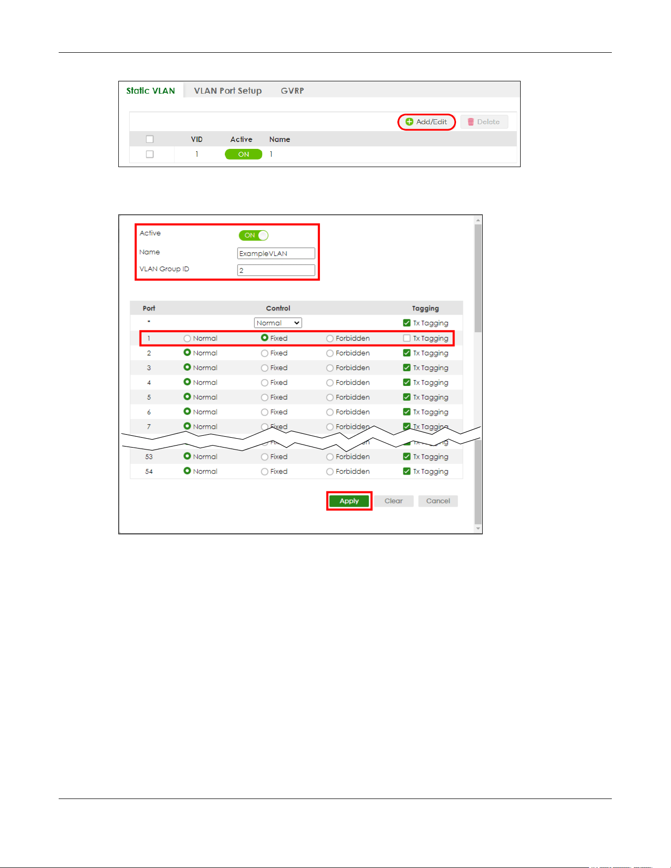
Chapter 5 Initial Setup Example
XGS2220 Series User’s Guide
102
2 The following screen appears. Click the switch to set this VLAN to Active, enter a descriptive name in the
Name field and enter “2” in the VLAN Group ID field for the VLAN2 network.
Note: The VLAN Group ID field in this screen and the VID field in the SYSTEM > IP Setup > IP
Status screen refer to the same VLAN ID.
3 Since the VLAN2 network is connected to port 1 on the Switch, select Fixed to configure port 1 to be a
permanent member of the VLAN only.
4 To ensure that VLAN-unaware devices (such as computers and hubs) can receive frames properly, clear
the Tx Tagging check box to set the Switch to remove VLAN tags before sending.
5 Click Apply to save the settings to the run-time memory. Settings in the run-time memory are lost when
the Switch’s power is turned off.
5.1.2 Set Port VID
Use PVID to add a tag to incoming untagged frames received on that port so that the frames are
forwarded to the VLAN group that the tag defines.
In the example network, configure 2 as the port VID on port 1 so that any untagged frames received on

Chapter 5 Initial Setup Example
XGS2220 Series User’s Guide
103
that port get sent to VLAN 2.
Figure 73 Initial Setup Network Example: Port VID
1 Go to the SWITCHING > VLAN > VLAN Setup > VLAN Port Setup screen.
2 Enter 2 in the PVID field for port 1 and click Apply to save your changes back to the run-time memory.
Settings in the run-time memory are lost when the Switch’s power is turned off.
5.1.3 Configure Switch Management IP Address
If the Switch fails to obtain an IP address from a DHCP server, the Switch will use 192.168.1.1 as the
management IP address. You can configure another IP address in a different subnet for management
purposes. The following figure shows an example.

Chapter 5 Initial Setup Example
XGS2220 Series User’s Guide
104
Figure 74 Initial Setup Example: Management IP Address
1 Connect your computer to any Ethernet port on the Switch. Make sure your computer is in the same
subnet as the Switch.
2 Open your web browser and enter “setup.zyxel” or “192.168.1.1” (the default IP address) in the address
bar to access the Web Configurator. See Section 4.2 on page 58 for more information.
Note: You can always use the domain name “setup.zyxel” to access the Web Configurator
whether the Switch is using a DHCP-assigned IP or static IP address. This requires your PC
to be directly connected to the Switch.
3 Go to the SYSTEM > IP Setup > IP Setup screen. Click Add/Edit.
The following screen appears.

Chapter 5 Initial Setup Example
XGS2220 Series User’s Guide
105
4 For the VLAN2 network, enter 192.168.2.1 as the IP address and 255.255.255.0 as the subnet mask.
5 In the VID field, enter the ID of the VLAN group to which you want this management IP address to
belong. In this example, enter VLAN ID 2. This is the same as the VLAN ID you configure in the Static VLAN
screen.
6 Click Apply to save your changes back to the run-time memory. Settings in the run-time memory are lost
when the Switch’s power is turned off.

Chapter 6 Tutorials
XGS2220 Series User’s Guide
106
CHAPTER 6
Tutorials
6.1 Overview
This chapter provides some examples of using the Web Configurator to set up and use the Switch. The
tutorials include:
• How to Use DHCPv4 Snooping on the Switch
• How to Use DHCPv4 Relay on the Switch
• How to Use Auto Configuration through a DHCP Server on the Switch
6.2 How to Use DHCPv4 Snooping on the Switch
You only want DHCP server A connected to port 5 to assign IP addresses to all devices in VLAN network
(V). Create a VLAN containing ports 4, 5 and 6. Connect a computer M to the Switch for management.
Figure 75 Tutorial: DHCP Snooping Tutorial Overview
The settings in this tutorial are as the following.
1 Access the Switch through http://192.168.1.1 by default. Log into the Switch by entering the user name
(default: admin) and password (default: 1234).
Table 32 Tutorial: Settings in this Tutorial
HOST PORT CONNECTED VLAN PVID DHCP SNOOPING PORT TRUSTED
DHCP Server (A) 4 1 and 100 100 Yes
DHCP Client (B) 5 1 and 100 100 No
DHCP Client (C) 6 1 and 100 100 No

Chapter 6 Tutorials
XGS2220 Series User’s Guide
107
2 Go to SWITCHING > VLAN > VLAN Setup > Static VLAN. Click Add/Edit.
3 The following screen appears. Enable the switch button to set this VLAN to ACTIVE. Create a VLAN with
ID of 100. Add ports 4, 5 and 6 in the VLAN by selecting Fixed in the Control field as shown.
De-select Tx Tagging because you do not want outgoing traffic to contain this VLAN tag.
Click Apply.
4 Go to SWITCHING > VLAN > VLAN Setup > VLAN Port Setup, and set the PVID of the ports 4, 5 and 6 to
100. This tags untagged incoming frames on ports 4, 5 and 6 with the tag 100. Click Apply.
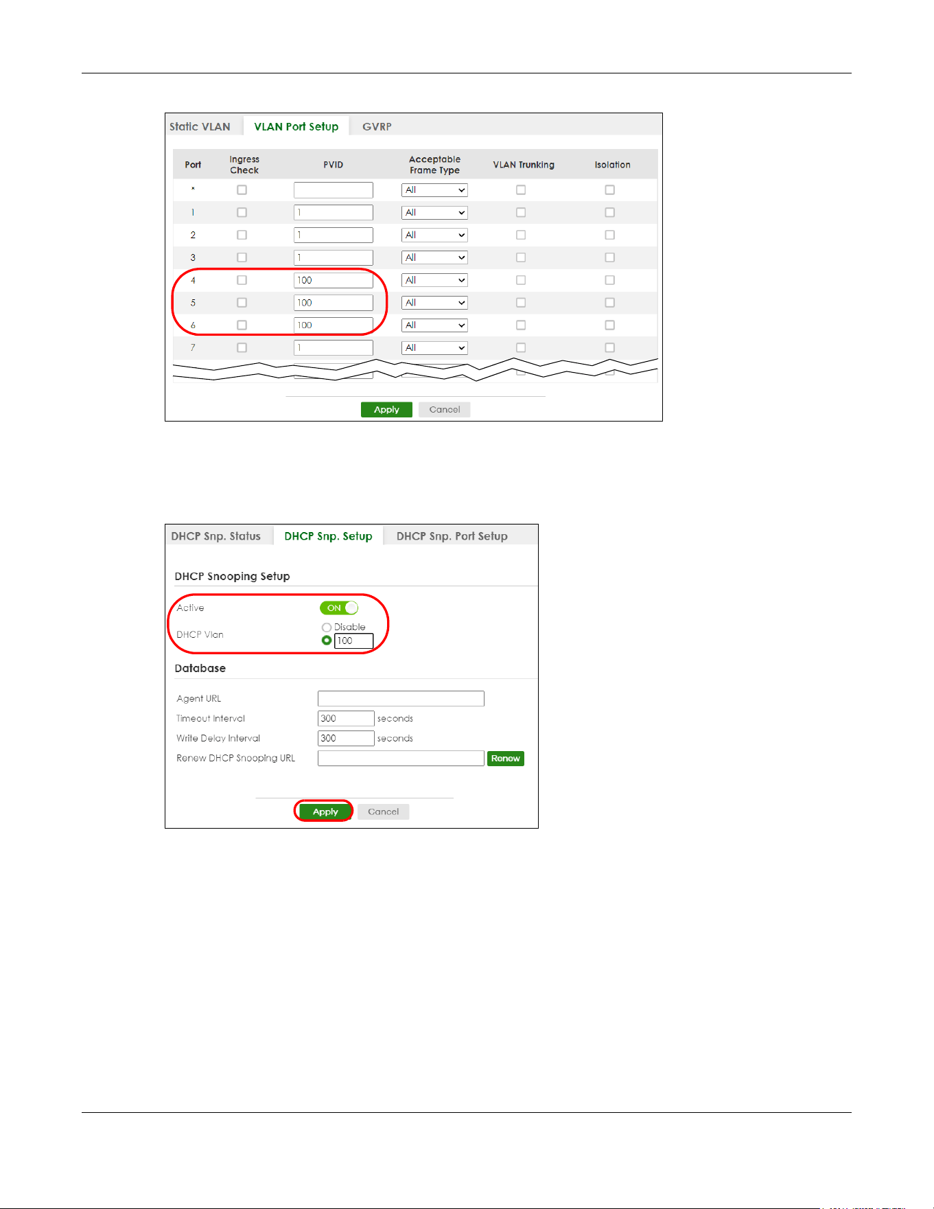
Chapter 6 Tutorials
XGS2220 Series User’s Guide
108
Tutorial: Tag Untagged Frames
5 Go to SECURITY > DHCP Snooping > DHCP Snp. Setup, activate and specify VLAN 100 as the DHCP VLAN
as shown. Click Apply.
IP requests from VLANs you enable on the SECURITY > DHCP Snooping > DHCP Snp. VLAN Setup screen
will be broadcast to the DHCP VLAN you set on this screen, which is VLAN100 in this example.
Tutorial: Specify DH CP VLAN
6 Go to SECURITY > DHCP Snooping > DHCP Snp. Port Setup. Select Trusted in the Server Trusted state field
for port 4 because the DHCP server is connected to port 4. Keep ports 5 and 6 Untrusted because they
are connected to DHCP clients. Click Apply.

Chapter 6 Tutorials
XGS2220 Series User’s Guide
109
7 Go to SECURITY > DHCP Snooping > DHCP Snp. VLAN Setup, show VLAN 100 by entering 100 in the VLAN
Search by VID field and click Search.
Select Yes in the Enabled field of the VLAN 100 entry shown in the search result. Click Apply.
This enables DHCP snooping on VLAN100 (and other VLANs you enabled on this screen).
If you want the Switch to add more information in the DHCP request packets, such as source VLAN ID or
system name, you can select an Option82 Profile in the entry. The Switch will add DHCP option 82
information to DHCP requests that the Switch relays to a DHCP server for the specified VLAN.
8 Connect your DHCP server to port 4 and a DHCP client (an AP, for example) to either port 5 or 6. The AP
should be able to get an IP address from the DHCP server. If you put the DHCP server on port 5 or 6, the
computer will NOT be able to get an IP address.
9 Click Save at the top right of the Web Configurator to save the configuration permanently.
10 To check if DHCP snooping works, go to SECURITY > IPv4 Source Guard > IP Source Guard, you should
see an IP assignment with the type DHCP-Snooping as shown.
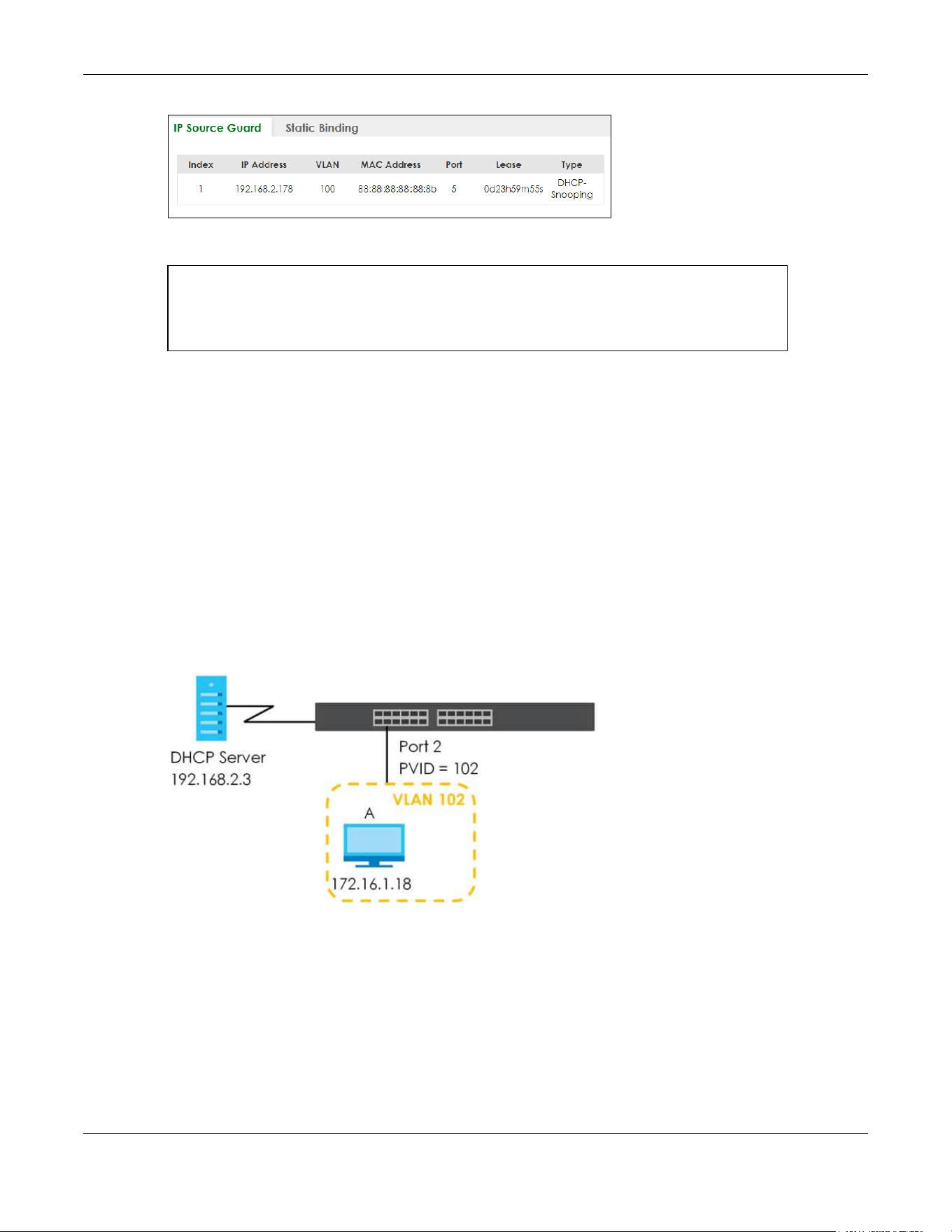
Chapter 6 Tutorials
XGS2220 Series User’s Guide
110
You can also use telnet. Use the command “show dhcp snooping binding” to see the DHCP
snooping binding table as shown next.
6.3 How to Use DHCPv4 Relay on the Switch
This tutorial describes how to configure your Switch to forward DHCP client requests to a specific DHCP
server. The DHCP server can then assign a specific IP address based on the information in the DHCP
requests.
6.3.1 DHCP Relay Tutorial Introduction
In this example, you have configured your DHCP server (192.168.2.3) and want to have it assign a
specific IP address (say 172.16.1.18) to DHCP client A based on the system name, VLAN ID and port
number in the DHCP request. Client A connects to the Switch’s port 2 in VLAN 102.
Figure 76 Tutorial: DHCP Relay Scenario
6.3.2 Create a VLAN
Follow the steps below to configure port 2 as a member of VLAN 102.
1 Access the Web Configurator through the Switch’s management port.
2 Go to SYSTEM > Switch Setup and set the VLAN Type to 802.1Q. Click Apply to save the settings to the
run-time memory.
sysname# show dhcp snooping binding
MacAddress IpAddress Lease Type VLAN Port
----------------- --------------- ------------ ------------- ---- -----
88:88:88:88:88:8b 192.168.2.178 0d23h59m20s dhcp-snooping 100 5
Total number of bindings: 1

Chapter 6 Tutorials
XGS2220 Series User’s Guide
111
3 Go to SWITCHING > VLAN > VLAN Setup > Static VLAN. Click Add/Edit.
4 The following screen appears. Enable the switch button to set this VLAN to Active. Enter a descriptive
name (VLAN 102 for example) in the Name field and enter “102” in the VLAN Group ID field.

Chapter 6 Tutorials
XGS2220 Series User’s Guide
112
5 Set port 2 to be a permanent member of this VLAN by selecting Fixed in the Control field.
6 Clear the Tx Tagging check box to set the Switch to remove VLAN tags before sending.
7 Click Apply to save the settings to the run-time memory. Settings in the run-time memory are lost when
the Switch’s power is turned off.
8 Go to VLAN > VLAN Setup >VLAN Port Setup. Enter “102” in the PVID field for port 2 to add a tag to
incoming untagged frames received on that port so that the frames are forwarded to the VLAN group
that the tag defines.
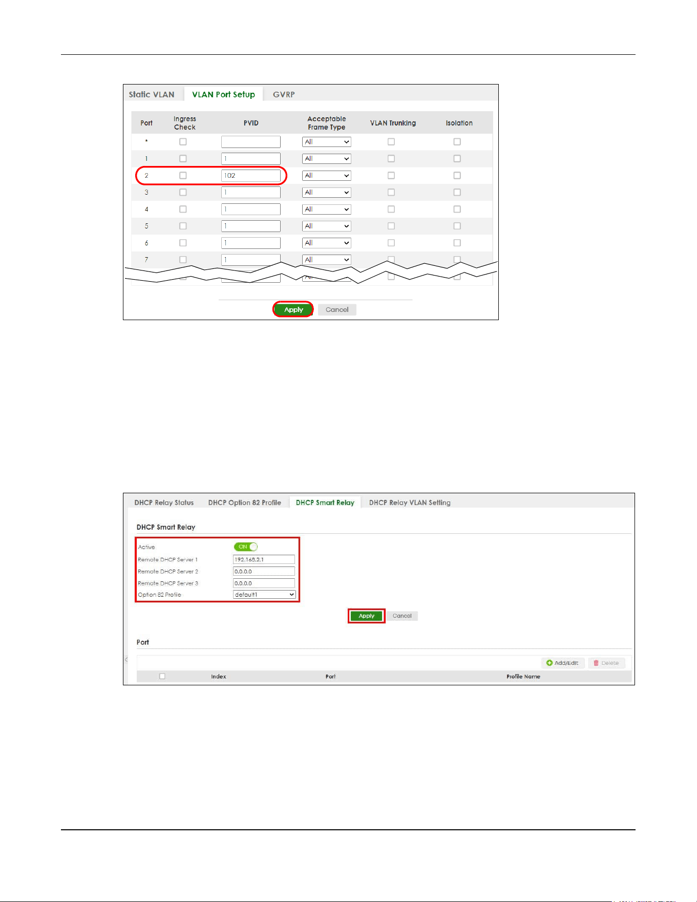
Chapter 6 Tutorials
XGS2220 Series User’s Guide
113
9 Click Apply to save your changes back to the run-time memory.
10 Click the Save link in the upper right of the Web Configurator to save your configuration permanently.
6.3.3 Configure DHCPv4 Relay
Follow the steps below to enable DHCP relay on the Switch and allow the Switch to add relay agent
information (such as the VLAN ID) to DHCP requests.
1 Click NETWORKING > DHCP > DHCPv4 Relay > DHCP Smart Relay. Enable the Active switch button.
2 Enter the DHCP server’s IP address (192.168.2.3 in this example) in the Remote DHCP Server 1 field.
3 Select default1 or default2 in the Option 82 Profile field.
4 Click Apply to save your changes back to the run-time memory.
5 Click the Save link in the upper right of the Web Configurator to save your configuration permanently.
6 The DHCP server can then assign a specific IP address based on the DHCP request.

Chapter 6 Tutorials
XGS2220 Series User’s Guide
114
6.3.4 Troubleshooting
Check client A’s IP address. If it did not receive the IP address 172.16.1.18, make sure:
1 Client A is connected to the Switch’s port 2 in VLAN 102.
2 You configured the correct VLAN ID, port number and system name for DHCP relay on both the DHCP
server and the Switch.
3 You clicked the Save link on the Switch to have your settings take effect.
6.4 How to Use Auto Configuration through a DHCP Server
on the Switch
Follow the steps below to set up configurations on a DHCP server, TFTP server, and the Switch, so you
can load an auto configuration file automatically from a TFTP server when you reboot the Switch.
Note that you can set up a DHCP server and TFTP server either on the same device or different devices.
Also, make sure the Switch can communicate with the TFTP server.
Note: Steps order could vary according to different programs you use.
Note: You need to set up configurations on a DHCP server and TFTP server first to use auto
configuration.
Setting up a DHCP Server
1 Set up a dynamic IP addresses pool so the DHCP server will assign an IP address to the Switch in that
range.
2 Set up a TFTP server IP address, so the Switch will know where to load the auto configuration file.
3 Set up the filename of the auto configuration file, so the Switch will know which file to load when you
reboot the Switch.
• Enter the filename of an auto configuration file. The Switch will load this auto configuration file
when rebooting with DHCP option 60 disabled.
• If you want to load the auto configuration file with DHCP option 60 enabled and a Vendor Class
Identifier assigned when you reboot the Switch, follow the instruction below. Otherwise, skip this
step.
Enter the filename of an auto configuration file. Set up a Vendor Class Identifier. To have the
Switch load this auto configuration file, two conditions listed above must be met. Please refer to
the following steps to see how to set up a Vendor Class Identifier on the Switch.
Setting up a TFTP Server
1 Select a directory on the TFTP server.
2 Put the configuration files in that directory.

Chapter 6 Tutorials
XGS2220 Series User’s Guide
115
Setting Up the Switch
1 Open the Web Configurator. Go to the MAINTENANCE > Configuration > Auto Configuration screen.
2 Enable the switch button in the Active field to enable auto configuration. Select DHCP in the Mode field,
and enter the VLAN ID where the DHCP server belongs to in the DHCP VLAN ID field. Click Apply to save
your changes.
3 Go to the SYSTEM > IP Setup > IP Setup screen. Click the Add/Edit button in the IP Interface table to open
the configuration screen.
4 Select DHCP Client.
5 If you want to load the auto configuration file with DHCP option 60 enabled and a Vendor Class
Identifier assigned when you reboot the Switch, follow the instruction below. Otherwise, skip this step. In
the SYSTEM > IP Setup > IP Setup > Add/Edit screen, select the check box in the Option-60 field. Enter a
Vendor Class Identifier in the Class-ID field, and specify the VLAN interface in the VID field. In this
example, we use “Zyxel Corp” and VID 1. Click Apply.
6 You need to save the current configuration in a configuration file, so the Switch will load the auto
configuration file from the TFTP server automatically when rebooting. Go to the MAINTENANCE >
Configuration > Save Configuration screen. Click the Config 1, Config 2, or Custom Default button.
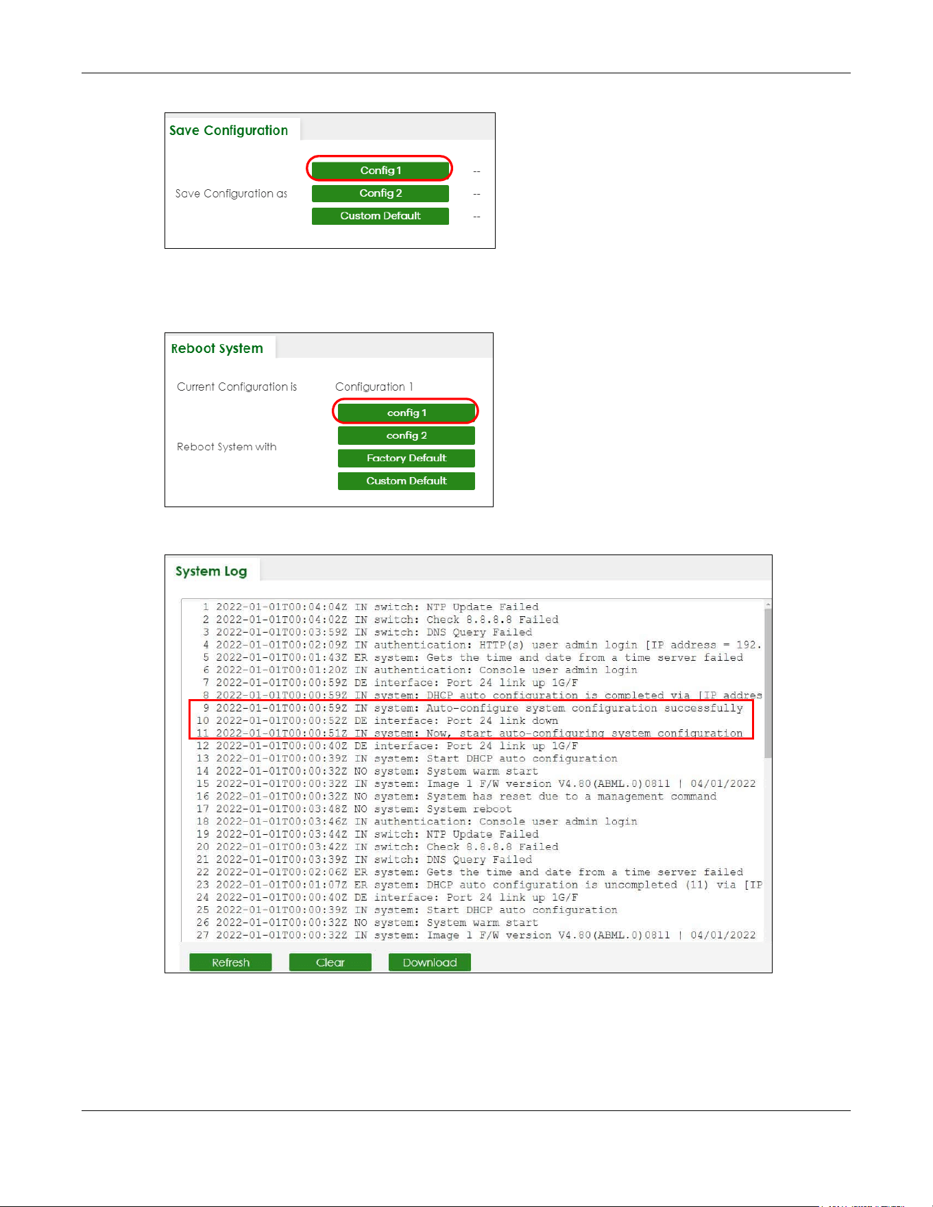
Chapter 6 Tutorials
XGS2220 Series User’s Guide
116
7 Click the same button in the MAINTENANCE > Reboot System screen to reboot the Switch, and load the
auto configuration setting as configured before. For example, if you save the auto configuration setting
to Config 1, you need to click the Config 1 button in the Reboot System screen.
8 Go to the MONITOR > System Log screen to see if auto configuration was performed successfully.
9 Check the screens to see if it is the configuration file you want to load. If it is not, go through the steps
above to check your configurations. If it is, click Save at the top right corner of the Web Configurator to
save the configuration permanently.

XGS2220 Series User’s Guide
117
CHAPTER 7
DASHBOARD
This chapter gives a quick introduction on the DASHBOARD screen.
The DASHBOARD screen automatically appears after you log into the Web Configurator.
7.1 New User Interface
With ZyNOS 4.80 and later, the Web Configurator’s user interface is restructured. In the new DASHBOARD
screen, you can easily monitor the system status with the following tools (see DASHBOARD for more
information):
• Visualized Port Status section with clickable port icons that provide information of that port, an ON/
OFF switch button to enable/disable the port, and a Power Cycle button to turn the power off to the
PoE port and then back on again (see Port Status).
• Visualized Cloud Control Status section that displays the NCC connection status using three
connection-stage circles.
• Clickable hardware status monitoring sections that directly link to the MONITOR > System Information
screen.
•Editable Quick Link section which provides shortcuts to configuration screens that you might
frequently use (See Quick Links to Use).
•A Search tool on the upper right of the screen that you can use to search for the configuration
screens you want to access (see Web Configurator Layout).
The left navigation panel is also restructured into task-based UI. You can display the sub-menu in the
MONITOR, SYSTEM, PORT, SWITCHING, NETWORKING, SECURITY, or the MAINTENANCE section by clicking
their icons. See Web Configurator Layout for more information.
Find the latest release note in: Download Library on www.zyxel.com.
7.2 DASHBOARD
This screen displays general device information, system status, system resource usage, and port status.
This guide uses XGS2220-54FP screens as an example. The screens may vary slightly for different models.
Click DASHBOARD in the navigation panel to open the following screen.
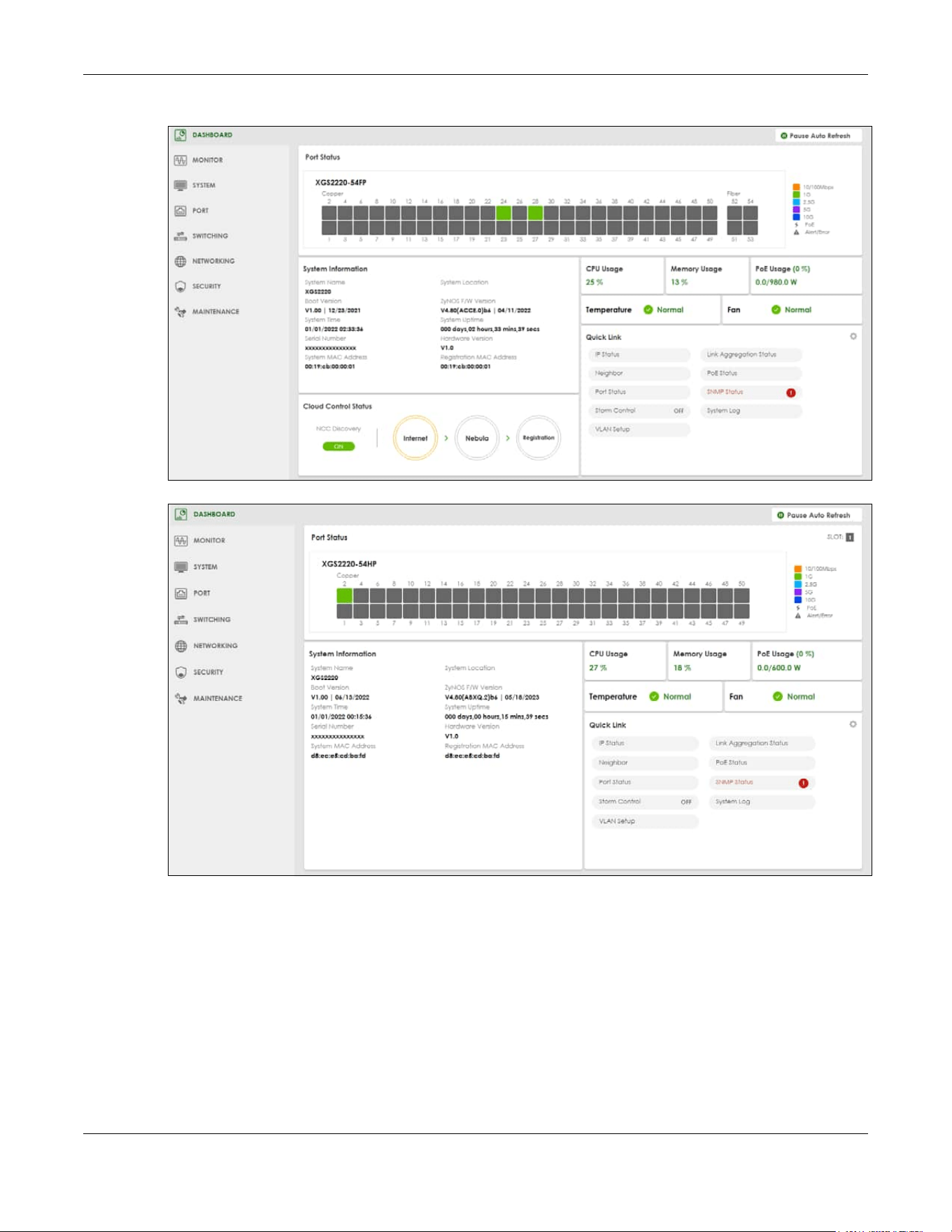
Chapter 7 DASHBOARD
XGS2220 Series User’s Guide
118
Figure 77 DASHBOARD (Standalone Mode, example PoE model)
Figure 78 DASHBOARD (Stacking Mode, example PoE model)

Chapter 7 DASHBOARD
XGS2220 Series User’s Guide
119
The following table describes the labels in this screen.
Table 33 DASHBOARD
LABEL DESCRIPTION
Pause Auto
Refresh
The DASHBOARD screen automatically refreshes every 30 seconds.
Click this to disable the auto refresh. Click Resume Auto Refresh to enable.
Port Status This displays individual port type, status, and connection speed of the Switch.
Click on a port to open the port’s status panel. Use the status panel to enable/disable a port
and view its basic information. For example, link speed and port utilization.
In Stacking mode, this displays the port status of the slot (Switch) selected in the SLOT field.
Note: The port status may vary for non-PoE and PoE models.
SLOT This appears only in Stacking mode.
Click the index to choose the slot number of a Switch in the stacking system.
System Information
System
Name
This field displays the name used to identify the Switch on any network.
System
Location
This field displays the geographic location name you set for the Switch.
Boot Version This field displays the version number and date of the boot module that is currently on the
Switch.
ZyNOS F/W
Version
This field displays the version number and date of the firmware the Switch is currently running.
System Time This field displays the current date and time in the UAG. The format is mm/dd/yyyy hh:mm:ss.
System
Uptime
This field displays how long the Switch has been running since it last restarted or was turned on.
Serial
Number
This field displays the serial number of this Switch. The serial number is used for device tracking
and control.
Hardware
Version
This field displays the hardware version of the Switch.
System MAC
Address
This field displays the MAC address of the Switch.
Registration
MAC
Address
This is the MAC address reserved for NCC registration. Use this MAC address to register the Switch
on NCC.

Chapter 7 DASHBOARD
XGS2220 Series User’s Guide
120
Cloud Control
Status
This field does not appear in Stacking mode.
This field displays:
• The Switch Internet connection status.
• The connection status between the Switch and NCC.
• The Switch registration status on NCC.
Mouse over the circles to display detailed information.
To pass your Switch management to NCC, first make sure your Switch is connected to the
Internet. Then go to NCC and register your Switch.
Click Cloud Control Status or the switch button to go to the SYSTEM > Cloud Management
screen. You can enable/disable NCC Discovery or view the NCC connection status in the Cloud
Management screen.
1. Internet
Green – The Switch is connected to the Internet.
Orange – The Switch is not connected to the Internet.
2. Nebula
Green – The Switch is connected to NCC.
Orange – The Switch is not connected to NCC.
3. Registration
Green – The Switch is registered on NCC.
Gray – The Switch is not registered on NCC.
Note: All circles will gray out if you disable Nebula Discovery.
Note: If a circle displays orange or gray, hover the mouse over the circle to check the
diagnostic message.
NCC
Discovery
This field does not appear in Stacking mode.
This displays if NCC discovery is enabled on the Switch. The Switch will connect to NCC and
change to the NCC management mode if it:
• is connected to the Internet.
• has been registered on NCC.
CPU Usage This displays the current CPU usage percentage.
Click to go to the MONITOR > System Information screen to check the detailed information.
Memory Usage This displays the current RAM usage percentage.
Click to go to the MONITOR > System Information screen to check the detailed information.
PoE Usage For PoE models.
This field displays the amount of power the Switch is currently supplying to the connected PoE-
enabled devices and the total power the Switch can provide to the connected PDs. It also
shows the percentage of PoE power usage.
When PoE usage reaches 100%, the Switch will shut down PDs one-by-one according to the PD
priority which you configured in PORT > PoE Setup > PoE Setup.
Table 33 DASHBOARD (continued)
LABEL DESCRIPTION

Chapter 7 DASHBOARD
XGS2220 Series User’s Guide
121
7.2.1 Port Status
The Port Status section provides visualized port status for monitoring. Each port displays a status color
determined by the their link speed.
Figure 79 Port Status (example PoE model)
Click on a port to display a port’s status pane.
Figure 80 Port details Pane (example PoE model)
The port details pane includes the Power Cycle button for PoE models (turn the power off and then
back on again), displays information such as link speed, status, PoE draw (for PoE models), port
utilization, up time and has an ON/OFF switch button. Click the switch button to enable/disable the port.
Temperature The Switch has temperature sensors that are capable of detecting and reporting if the
temperature rises above the threshold.
This displays the Switch’s current device temperature level.
Click to go to the MONITOR > System Information screen to check the detailed information.
Fan Each fan of the Switch has a sensor that is capable of detecting and reporting if the fan speed
falls below the threshold.
This displays the Switch’s overall fan speed status.
Click to go to the MONITOR > System Information screen to check the detailed information.
Quick Link This section provides shortcut links to specific configuration screens.
Click the edit button to choose the quick links to show.
Table 33 DASHBOARD (continued)
LABEL DESCRIPTION
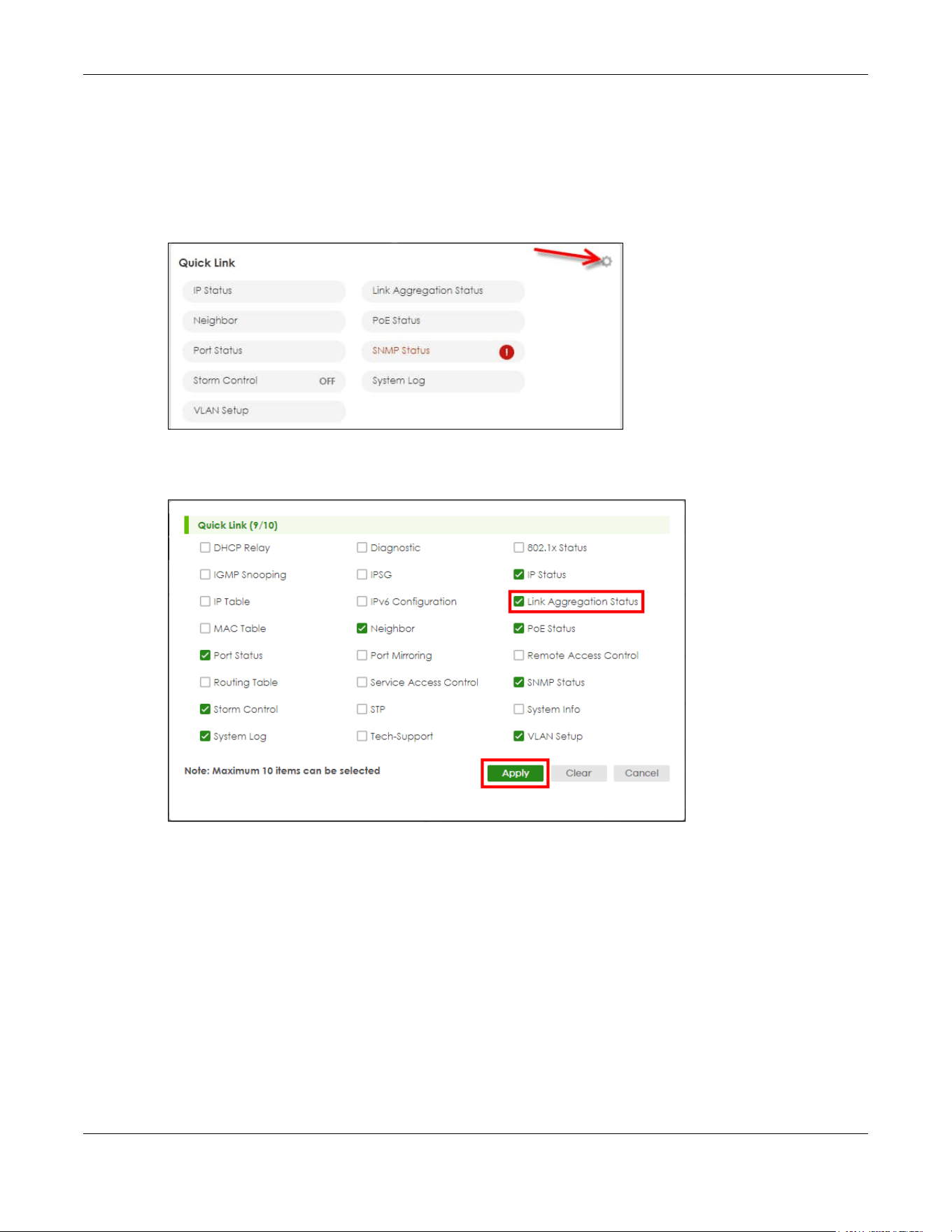
Chapter 7 DASHBOARD
XGS2220 Series User’s Guide
122
7.2.2 Quick Links to Use
The quick links in the Quick Link section provide shortcuts to specific configuration screens. You can use
the quick links to directly access the screens that you would frequently use. You can also decide which
quick links to be put on the DASHBOARD screen using the Edit button.
Figure 81 Quick Links (example PoE model)
The setup panel displays after you click the Edit button.
Figure 82 Quick Link Selection (example PoE model)
Select the quick links you want and click Apply. The selected quick links will be displayed in the Quick
Link section on the DASHBOARD screen.

Chapter 8 MONITOR
XGS2220 Series User’s Guide
123
CHAPTER 8
MONITOR
The following chapters introduces the configurations of the links under the MONITOR navigation panel.
Quick links to chapters:
• ARP Table
• IP Table
• IPv6 Neighbor Table
• MAC Table
• Neighbor
• Path MTU Table
• Port Status
• Routing Table
• System Information
• System Log

Chapter 9 ARP Table
XGS2220 Series User’s Guide
124
CHAPTER 9
ARP Table
9.1 ARP Table Overview
This chapter introduces the ARP Table.
Address Resolution Protocol (ARP) is a protocol for mapping an Internet Protocol address (IP address) to
a physical machine address, also known as a Media Access Control or MAC address, on the local area
network.
An IP (version 4) address is 32 bits long. In an Ethernet LAN, MAC addresses are 48 bits long. The ARP
Table maintains an association between each MAC address and its corresponding IP address.
9.1.1 What You Can Do
Use the ARP Table screen (Section 9.2 on page 124) to view IP-to-MAC address mappings.
9.1.2 What You Need to Know
When an incoming packet destined for a host device on a local area network arrives at the Switch, the
Switch's ARP program looks in the ARP Table and if it finds the address, it sends it to the device.
If no entry is found for the IP address, ARP broadcasts the request to all the devices on the LAN. The
Switch fills in its own MAC and IP address in the sender address fields, and puts the known IP address of
the target in the target IP address field. In addition, the Switch puts all ones in the target MAC field
(FF.FF.FF.FF.FF.FF is the Ethernet broadcast address). The replying device (which is either the IP address of
the device being sought or the router that knows the way) replaces the broadcast address with the
target's MAC address, swaps the sender and target pairs, and unicasts the answer directly back to the
requesting machine. ARP updates the ARP Table for future reference and then sends the packet to the
MAC address that replied.
9.2 Viewing the ARP Table
Use the ARP table to view IP-to-MAC address mappings and remove specific dynamic ARP entries.
Click MONITOR > ARP Table in the navigation panel to open the following screen.

Chapter 9 ARP Table
XGS2220 Series User’s Guide
125
Figure 83 MONITOR > ARP Table
The following table describes the labels in this screen.
Table 34 MONITOR > ARP Table
LABEL DESCRIPTION
Condition Specify how you want the Switch to remove ARP entries when you click Flush.
Select All to remove all of the dynamic entries from the ARP table.
Select IP Address and enter an IP address to remove the dynamic entries learned with the
specified IP address.
Select Port and enter a port number to remove the dynamic entries learned on the specified port.
You can enter multiple ports separated by (no space) comma (,) or hyphen (-) for a range. For
example, enter “3-5” for ports 3, 4, and 5. Enter “3,5,7” for ports 3, 5, and 7.
Flush Click Flush to remove the ARP entries according to the condition you specified.
Cancel Click Cancel to return the fields to the factory defaults.
Index This is the ARP table entry number.
IP Address This is the IP address of a device connected to a Switch port with the corresponding MAC address
below.
MAC Address This is the MAC address of the device with the corresponding IP address above.
VID This field displays the VLAN to which the device belongs.
Port This field displays the port to which the device connects. CPU means this IP address is the Switch’s
management IP address. In stacking mode, the first number represents the slot and the second
the port number.
Age(s) This field displays how long (in seconds) an entry can still remain in the ARP table before it ages out
and needs to be relearned. This shows 0 for a static entry.
Type This shows whether the IP address is dynamic (learned by the Switch) or static (manually
configured in SYSTEM > IP Setup > IP Setup or NETWORKING > ARP Setup > Static ARP).

Chapter 10 IP Table
XGS2220 Series User’s Guide
126
CHAPTER 10
IP Table
This chapter introduces the IP table screen.
10.1 IP Table Overview
The IP Table screen shows how packets are forwarded or filtered across the Switch’s ports. When a
device (which may belong to a VLAN group) sends a packet which is forwarded to a port on the Switch,
the IP address of the device is shown on the Switch’s IP Table. The IP Table also shows whether the IP
address is dynamic (learned by the Switch) or static (belonging to the Switch).
The Switch uses the IP Table to determine how to forward packets. See the following figure.
1 The Switch examines a received packet and learns the port from which this source IP address came.
2 The Switch checks to see if the packet's destination IP address matches a source IP address already
learned in the IP Table.
• If the Switch has already learned the port for this IP address, then it forwards the packet to that
port.
• If the Switch has not already learned the port for this IP address, then the packet is flooded to all
ports. Too much port flooding leads to network congestion then the Switch sends an ARP to request
the MAC address. The Switch then learns the port that replies with the MAC address.
• If the Switch has already learned the port for this IP address, but the destination port is the same as
the port it came in on, then it filters the packet.
Figure 84 IP Table Flowchart
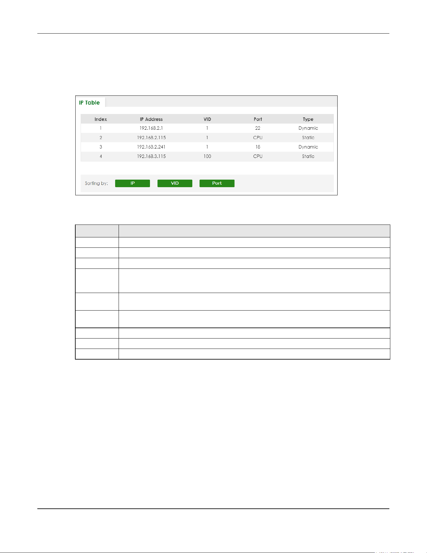
Chapter 10 IP Table
XGS2220 Series User’s Guide
127
10.2 Viewing the IP Table
Click MONITOR > IP Table in the navigation panel to display the following screen.
Figure 85 MONITOR > IP Table
The following table describes the labels in this screen.
Table 35 MONITOR > IP Table
LABEL DESCRIPTION
Index This field displays the index number.
IP Address This is the IP address of the device from which the incoming packets came.
VID This is the VLAN group to which the packet belongs.
Port This is the port from which the above IP address was learned. This field displays CPU to indicate the
IP address belongs to the Switch. In stacking mode, the first number represents the slot and the
second the port number.
Type This shows whether the IP address is Dynamic (learned by the Switch) or Static (belonging to the
Switch).
Sorting by Click one of the following buttons to display and arrange the data according to that button type.
The result is then displayed in the IP table.
IP Click this button to display and arrange the data according to IP address.
VID Click this button to display and arrange the data according to VLAN group.
Port Click this button to display and arrange the data according to port number.

Chapter 11 IPv6 Neighbor Table
XGS2220 Series User’s Guide
128
CHAPTER 11
IPv6 Neighbor Table
11.1 IPv6 Neighbor Table Overview
This chapter introduces the IPv6 neighbor table.
An IPv6 host is required to have a neighbor table. If there is an address to be resolved or verified, the
Switch sends out a neighbor solicitation message. When the Switch receives a neighbor advertisement
in response, it stores the neighbor’s link-layer address in the neighbor table. You can also manually
create a static IPv6 neighbor entry using the SYSTEM > IPv6 > IPv6 Neighbor Setup screen.
When the Switch needs to send a packet, it first consults other table to determine the next hop. Once
the next hop IPv6 address is known, the Switch looks into the neighbor table to get the link-layer address
and sends the packet when the neighbor is reachable. If the Switch cannot find an entry in the
neighbor table or the state for the neighbor is not reachable, it starts the address resolution process. This
helps reduce the number of IPv6 solicitation and advertisement messages.
11.2 Viewing the IPv6 Neighbor Table
Use this screen to view IPv6 neighbor information on the Switch. Click MONITOR > IPv6 Neighbor Table in
the navigation panel to display the screen as shown.
Figure 86 MONITOR > IPv6 Neighbor Table
The following table describes the labels in this screen.
Table 36 MONITOR > IPv6 Neighbor Table
LABEL DESCRIPTION
Index This field displays the index number of each entry in the table.
Address This field displays the IPv6 address of the Switch or a neighboring device.
MAC This field displays the MAC address of the IPv6 interface on which the IPv6 address is configured or
the MAC address of the neighboring device.

Chapter 11 IPv6 Neighbor Table
XGS2220 Series User’s Guide
129
Status This field displays whether the neighbor IPv6 interface is reachable. In IPv6, “reachable” means an
IPv6 packet can be correctly forwarded to a neighbor node (host or router) and the neighbor
can successfully receive and handle the packet. The available options in this field are:
• reachable (R): The interface of the neighboring device is reachable. (The Switch has received
a response to the initial request.)
• stale (S): The last reachable time has expired and the Switch is waiting for a response to
another initial request. The field displays this also when the Switch receives an unrequested
response from the neighbor’s interface.
• delay (D): The neighboring interface is no longer known to be reachable, and traffic has been
sent to the neighbor recently. The Switch delays sending request packets for a short to give
upper-layer protocols a chance to determine reachability.
• probe (P): The Switch is sending request packets and waiting for the neighbor’s response.
• invalid (IV): The neighbor address is with an invalid IPv6 address.
• unknown (?): The status of the neighboring interface cannot be determined for some reason.
• incomplete (I): Address resolution is in progress and the link-layer address of the neighbor has
not yet been determined. The interface of the neighboring device did not give a complete
response.
Type This field displays the type of an address mapping to a neighbor interface. The available options in
this field are:
• other (O): none of the following type.
• local (L): A Switch interface is using the address.
• dynamic (D): The IP address to MAC address can be successfully resolved using IPv6 Neighbor
Discovery protocol. Is it similar as IPv4 ARP (Address Resolution protocol).
• static (S): The interface address is statically configured.
Interface This field displays the ID number of the IPv6 interface on which the IPv6 address is created or
through which the neighboring device can be reached.
Sorting by Click one of the following buttons to display and arrange the data according to that button type.
The result is then displayed in the summary table above.
Address Click this button to display and arrange the data according to IPv6 address.
MAC Click this button to display and arrange the data according to MAC address.
Interface Click this button to display and arrange the data according to IPv6 interface.
Table 36 MONITOR > IPv6 Neighbor Table (continued)
LABEL DESCRIPTION

Chapter 12 MAC Table
XGS2220 Series User’s Guide
130
CHAPTER 12
MAC Table
12.1 MAC Table Overview
This chapter introduces the MAC Table screen.
The MAC Table screen (a MAC table is also known as a filtering database) shows how frames are
forwarded or filtered across the Switch’s ports. It shows what device MAC address, belonging to what
VLAN group (if any) is forwarded to which ports and whether the MAC address is dynamic (learned by
the Switch) or static (manually entered in the SWITCHING > Static MAC Forwarding screen).
12.1.1 What You Can Do
Use the MAC Table screen (Section 12.2 on page 131) to check whether the MAC address is dynamic or
static.
12.1.2 What You Need to Know
The Switch uses the MAC Table to determine how to forward frames. See the following figure.
1 The Switch examines a received frame and learns the port on which this source MAC address came.
2 The Switch checks to see if the frame's destination MAC address matches a source MAC address
already learned in the MAC Table.
• If the Switch has already learned the port for this MAC address, then it forwards the frame to that port.
• If the Switch has not already learned the port for this MAC address, then the frame is flooded to all
ports. Too much port flooding leads to network congestion, then the Switch sends an ARP to request
the MAC address. The Switch then learns the port that replies with the MAC address.
• If the Switch has already learned the port for this MAC address, but the destination port is the same as
the port it came in on, then it filters the frame.

Chapter 12 MAC Table
XGS2220 Series User’s Guide
131
Figure 87 MAC Table Flowchart
12.2 Viewing the MAC Table
Use this screen to search specific MAC addresses. You can also directly add dynamic MAC addresses
into the static MAC forwarding table or MAC filtering table from the MAC table using this screen.
Click MONITOR > MAC Table in the navigation panel to display the following screen.
Figure 88 MONITOR > MAC Table

Chapter 12 MAC Table
XGS2220 Series User’s Guide
132
The following table describes the labels in this screen.
Table 37 MONITOR > MAC Table
LABEL DESCRIPTION
Condition Select one of the below search conditions and click Search to only display the data which
matches the criteria you specified.
Select All to display any entry in the MAC table of the Switch.
Select Static to display the MAC entries manually configured on the Switch.
Select MAC and enter a MAC address in the field provided to display a specified MAC entry.
Select VID and enter a VLAN ID in the field provided to display the MAC entries belonging to the
specified VLAN.
Select Port and enter a port number in the field provided to display the MAC addresses which
are forwarded on the specified port.
Select Trunk and type the ID of a trunk group to display all MAC addresses learned from the ports
in the trunk group.
Sort by Define how the Switch displays and arranges the data in the summary table below.
Select MAC to display and arrange the data according to MAC address.
Select VID to display and arrange the data according to VLAN group.
Select PORT to display and arrange the data according to port number.
Type Transfer Select Dynamic to MAC forwarding and click the Transfer button to change all dynamically
learned MAC address entries in the summary table below into static entries. They also display in
the SWITCHING > Static MAC Forwarding screen.
Select Dynamic to MAC filtering and click the Transfer button to change all dynamically learned
MAC address entries in the summary table below into MAC filtering entries. These entries will then
display only in the SWITCHING > Static MAC Filtering screen and the default filtering action is
Discard source.
Search Click this to search data in the MAC table according to your input criteria.
Transfer Click this to perform the MAC address transferring you selected in the Type Transfer field.
Cancel Click Cancel to change the fields back to their last saved values.
Index This is the incoming frame index number.
MAC Address This is the MAC address of the device from which this incoming frame came.
VID This is the VLAN group to which this frame belongs.
Port This is the port from which the above MAC address was learned. In Stacking mode, the first
number represents the slot and the second the port number.
Type This shows whether the MAC address is Dynamic (learned by the Switch) or Static (manually
entered in the SWITCHING > Static MAC Forwarding screen).
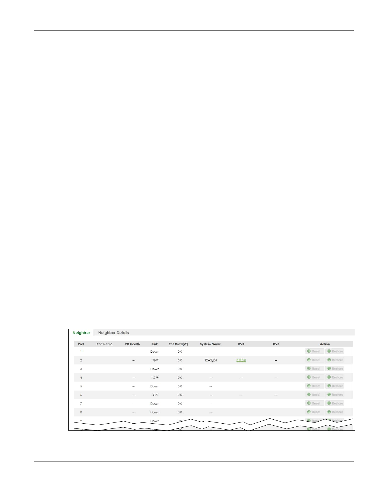
Chapter 13 Neighbor
XGS2220 Series User’s Guide
133
CHAPTER 13
Neighbor
13.1 Neighbor Overview
The Neighbor screen allows you to view a summary and manage the Switch’s neighboring devices. It
uses Layer Link Discovery Protocol (LLDP) to discover all neighbor devices connected to the Switch
including non-Zyxel devices. You can use this screen to perform tasks on the neighboring devices like
login, power cycle (turn the power off and then back on again), and reset to factory default settings.
This screen shows the neighboring device first recognized on an Ethernet port of the Switch. Device
information is displayed in gray when the neighboring device is offline.
13.1.1 What You Can Do
Use the Neighbor screen (Section 13.2 on page 133) to view a summary and manage the Switch’s
neighbor devices.
Use the Neighbor Details screen (Section 13.2.1 on page 135) to view more detailed information on the
Switch’s neighbor devices.
13.2 Neighbor
Click MONITOR > Neighbor to see the following screen.
Figure 89 MONITOR > Neighbor > Neighbor (Standalone Mode, example PoE model)

Chapter 13 Neighbor
XGS2220 Series User’s Guide
134
Figure 90 MONITOR > Neighbor > Neighbor (Stacking Mode, example PoE model)
The following table describes the fields in the above screen.
Table 38 MONITOR > Neighbor > Neighbor
LABEL DESCRIPTION
SLOT This field appears only in Stacking mode. Click the drop-down list to choose the slot number
of the Switch in a stack.
Port This shows the port of the Switch, on which the neighboring device is discovered. In
Stacking mode, the first number represents the slot ID and the second is the port number.
Please note that the default stacking ports (the last four ports of your Switch) cannot be
configured. They are reserved for stacking only.
Port Name This shows the port description of the Switch.
PD Health For PoE models.
This shows the status of auto PD recovery on this port.
• Red: The Switch failed to get information from the PD connected to the port using LLDP,
or the connected PD did not respond to the Switch’s ping requests.
• Yellow: The Switch is restarting the connected PD by turning the power off and turning it
on again.
• Green: The Switch successfully discovered the connected PD using LLDP or ping.
• –: Auto PD Recovery is not enabled on the Switch and the port, or the Switch does not
supply power to the connected PD.
Note: The status will NOT be updated instantaneously after enabling or disabling
the Active switch in the Port > Auto PD Recovery screen. It will wait until the
configured Resume Polling Interval (sec) has lapsed.
Link This shows the speed (either 10M for 10 Mbps, 100M for 100 Mbps, 1G for 1 Gbps, 2.5G for
2.5 Gbps, 5G for 5 Gbps, or 10G for 10 Gbps) and the duplex (F for full duplex or H for half).
This field displays Down if the port is not connected to any device.
PoE Draw (W) For PoE models.
This shows the consumption that the neighboring device connected to this port draws from
the Switch. This allows you to plan and use within the power budget of the Switch.
System Name This shows the system name of the neighbor device.
IPv4 This shows the IPv4 address of the neighbor device. The IPv4 address is a hyper link that you
can click to log into and manage the neighbor device through its Web Configurator.

Chapter 13 Neighbor
XGS2220 Series User’s Guide
135
13.2.1 Neighbor Details
Use this screen to view detailed information about the neighboring devices. Device information is
displayed in gray when the neighboring device is currently offline.
Up to 10 neighboring device records per Ethernet port can be retained in this screen even when the
devices are offline. When the maximum number of neighboring device records per Ethernet port is
reached, new device records automatically overwrite existing offline device records, starting with the
oldest existing offline device record first.
Click MONITOR > Neighbor > Neighbor Details to see the following screen.
IPv6 This shows the IPv6 address of the neighbor device. The IPv6 address is a hyper link that you
can click to log into and manage the neighbor device through its Web Configurator.
Action For PoE models.
Click the Reset button to turn OFF the power of the neighbor device and turn it back ON
again. A count down button (from 5 to 0) starts.
Note: The Switch must support power sourcing (PSE) or the network device is a
powered device (PD).
Click the Restore button to restore the neighboring device to its factory default settings. A
warning message “Are you sure you want to load factory default?” appears prompting you
to confirm the action. After confirming the action a count down button (from 5 to 0) starts.
Note:
• The Switch must support power sourcing (PSE) or the network device is a powered
device (PD).
• If multiple neighbor devices use the same port, the Reset button is not available.
• You can only reset Zyxel powered devices that support the ZON utility.
Table 38 MONITOR > Neighbor > Neighbor (continued)
LABEL DESCRIPTION
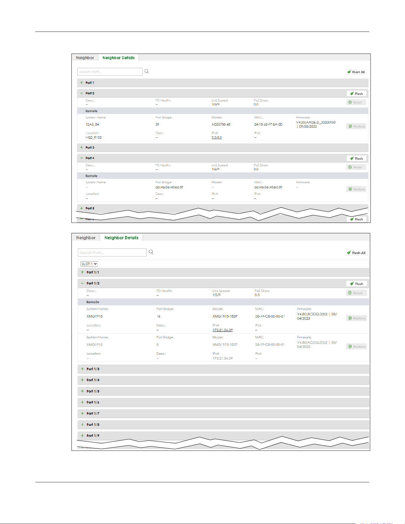
Chapter 13 Neighbor
XGS2220 Series User’s Guide
136
Figure 91 MONITOR > Neighbor > Neighbor Details (Standalone Mode, example PoE model)
Figure 92 MONITOR > Neighbor > Neighbor Details (Stacking Mode, example PoE model)

Chapter 13 Neighbor
XGS2220 Series User’s Guide
137
The following table describes the fields in the above screen.
Table 39 MONITOR > Neighbor > Neighbor Details
LABEL DESCRIPTION
Search Ports... Enter the port number to search and display the ports you specified. The result will display
in the below list.
You can enter multiple ports separated by comma (“,”) or hyphen (“-”) for a range. For
example, enter “3-5” for ports 3, 4, and 5. Enter “3,5,7” for ports 3, 5, and 7.
In Stacking mode, the first number represents the slot and the second the port number.
Enter “1/1-1/24,2/23” for ports 1 to 24 for the Switch in slot 1 and port 23 for the Switch in
slot 2, for example.
SLOT This field appears only in Stacking mode. Click the drop-down list to choose the slot
number of the Switch in a stack.
Port This shows the port of the Switch, on which the neighboring device is discovered.
Desc. This shows the port description of the Switch.
PD Health For PoE models.
This shows the status of auto PD recovery on this port.
• Red: The Switch failed to get information from the PD connected to the port using
LLDP, or the connected PD did not respond to the Switch’s ping requests.
• Yellow: The Switch is restarting the connected PD by turning the power off and
turning it on again.
• Green: The Switch successfully discovered the connected PD using LLDP or ping.
• –: Auto PD Recovery is not enabled on the Switch and the port, or the Switch does
not supply power to the connected PD.
Link Speed This shows the speed (either 10M for 10 Mbps, 100M for 100 Mbps, 1G for 1 Gbps, 2.5G for
2.5 Gbps, 5G for 5 Gbps, or 10G for 10 Gbps) and the duplex (F for full duplex or H for
half). This field displays Down if the port is not connected to any device.
PoE Draw (W) For PoE models.
This shows the consumption that the neighboring device connected to this port draws
from the Switch. This allows you to plan and use within the power budget of the Switch.
Reset Click this button to turn OFF the power of the neighbor device and turn it back ON again.
A count down button (from 5 to 0) starts.
Note: The Switch must support power sourcing (PSE) or the network device is a
powered device (PD).
Remote
System Name This shows the system name of the neighbor device.
Port Bridge This shows the neighboring device’s MAC address or the port number connected to the
Switch.
Model This shows the model name of the neighbor device. This field will show “–” for devices that
do not support the ZON utility.
MAC This shows the MAC address of the neighbor device.
Firmware This shows the firmware version of the neighbor device. This field will show “–” for devices
that do not support the ZON utility.
Location This shows the geographic location of the neighbor device. This field will show “–” for
devices that do not support the ZON utility.
Desc. This shows the description of the neighbor device’s port which is connected to the
Switch.
IPv4 This shows the IPv4 address of the neighbor device. The IPv4 address is a hyper link that
you can click to log into and manage the neighbor device through its Web Configurator.

Chapter 13 Neighbor
XGS2220 Series User’s Guide
138
IPv6 This shows the IPv6 address of the neighbor device. The IPv6 address is a hyper link that
you can click to log into and manage the neighbor device through its Web Configurator.
Restore Click this button to restore the neighbor device to its factory default settings. A warning
message “Are you sure you want to load factory default?” appears prompting you to
confirm the action. After confirming the action a count down button (from 5 to 0) starts.
Note:
• The Switch must support power sourcing (PSE) or the network device is a powered
device (PD).
• If multiple neighbor devices use the same port, the Reset button is not available.
• You can only reset Zyxel powered devices that support the ZON utility.
Flush Click the Flush button on the port tab to remove information about neighbors learned on
a specific ports.
Flush All Click the Flush All button to remove information about neighbors learned on all ports.
Table 39 MONITOR > Neighbor > Neighbor Details (continued)
LABEL DESCRIPTION
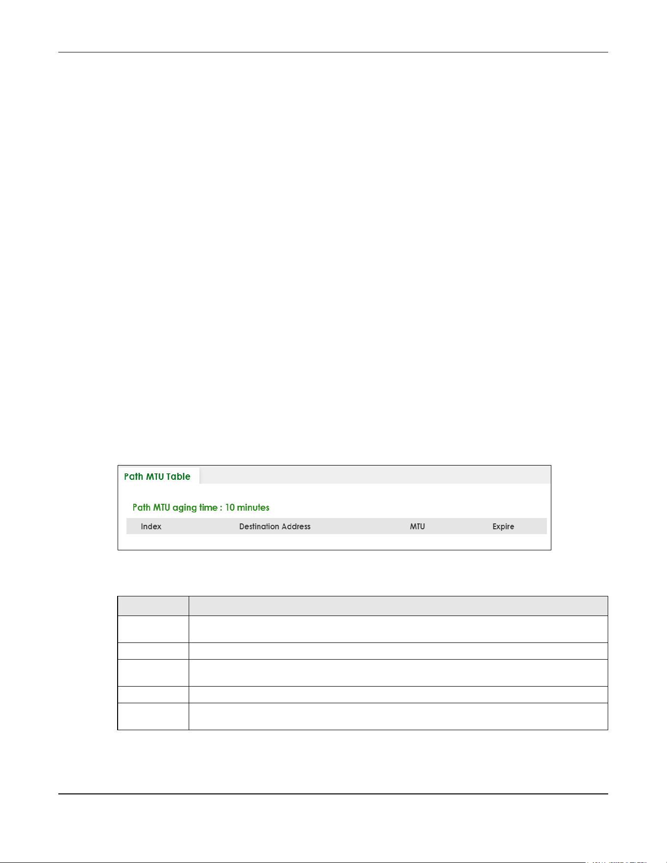
Chapter 14 Path MTU Table
XGS2220 Series User’s Guide
139
CHAPTER 14
Path MTU Table
14.1 Path MTU Overview
This chapter introduces the IPv6 Path MTU table.
The largest size (in bytes) of a packet that can be transferred over a data link is called the Maximum
Transmission Unit (MTU). The Switch uses Path MTU Discovery to discover Path MTU (PMTU), that is, the
minimum link MTU of all the links in a path to the destination. If the Switch receives an ICMPv6 Packet Too
Big error message after sending a packet, it fragments the next packet according to the suggested MTU
in the error message.
14.2 Viewing the Path MTU Table
Use this screen to view IPv6 path MTU information on the Switch. Click MONITOR > Path MTU Table in the
navigation panel to display the screen as shown.
Figure 93 MONITOR > Path MTU Table
The following table describes the labels in this screen.
Table 40 MONITOR > Path MTU Table
LABEL DESCRIPTION
Path MTU
aging time
This field displays how long an entry remains in the Path MTU table before it ages out and needs to
be relearned.
Index This field displays the index number of each entry in the table.
Destination
Address
This field displays the destination IPv6 address of each path or entry.
MTU This field displays the maximum transmission unit of the links in the path.
Expire This field displays how long (in minutes) an entry can still remain in the Path MTU table before it
ages out and needs to be relearned.
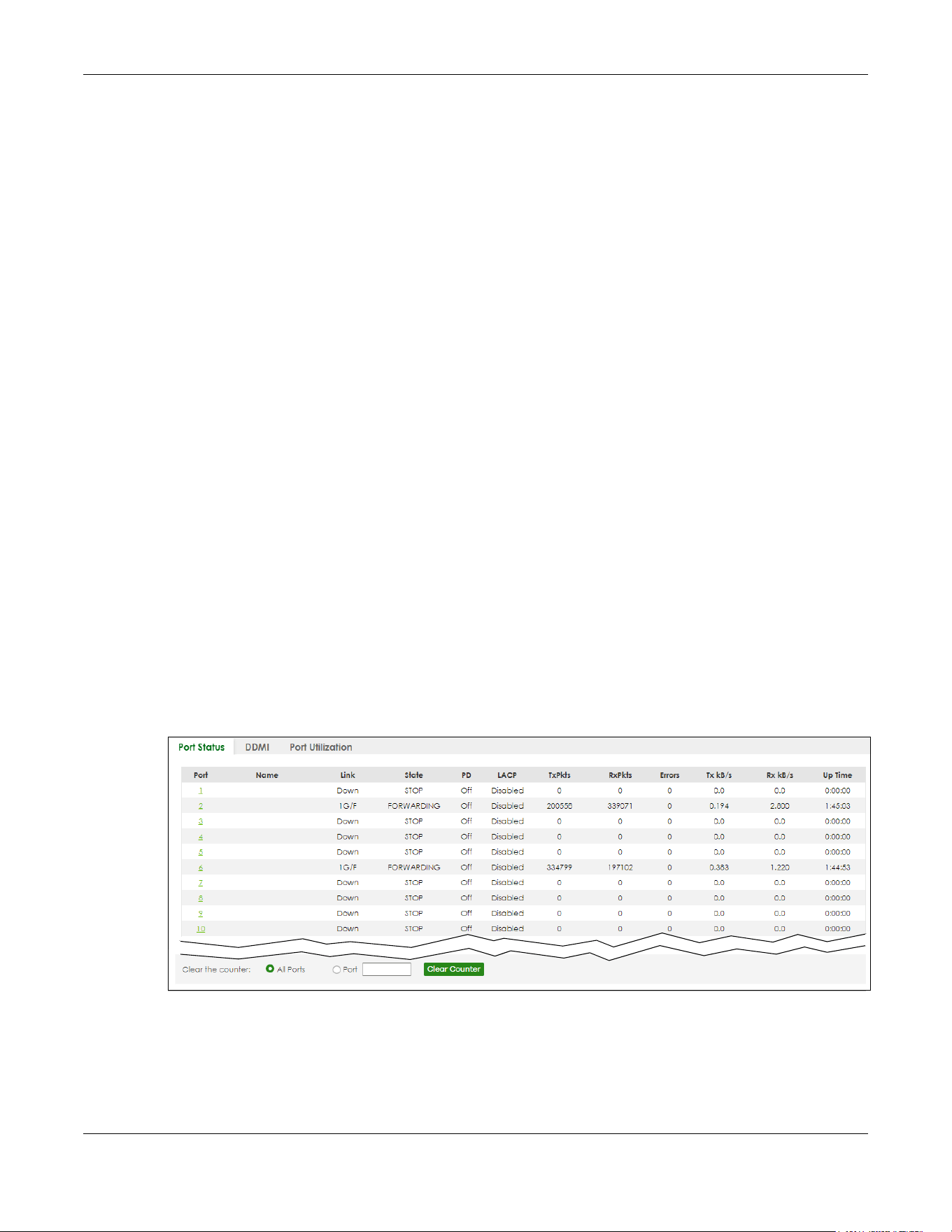
Chapter 15 Port Status
XGS2220 Series User’s Guide
140
CHAPTER 15
Port Status
This chapter introduces the Port Status screens.
15.0.1 What You Can Do
Use the Port Status screen (Section 15.1 on page 140) to view the port status of the Switch.
Use the DDMI screen (Section 15.2 on page 144) to view the DDMI (Digital Diagnostics Monitoring
Interface) status of the SFP transceivers on the Switch.
Use the Port Utilization screen (Section 15.3 on page 147) to view the current data rate and utilization
percentage of each port on the Switch.
15.1 Port Status
This screen displays a port statistical summary with links to each port showing statistical details. To view
the port statistics, click MONITOR > Port Status to display the Port Status screen as shown next. You can
also click the Port Status link in the Quick Link section of the DASHBOARD screen to see the following
screen.
Figure 94 MONITOR > Port Status > Port Status (Standalone Mode)
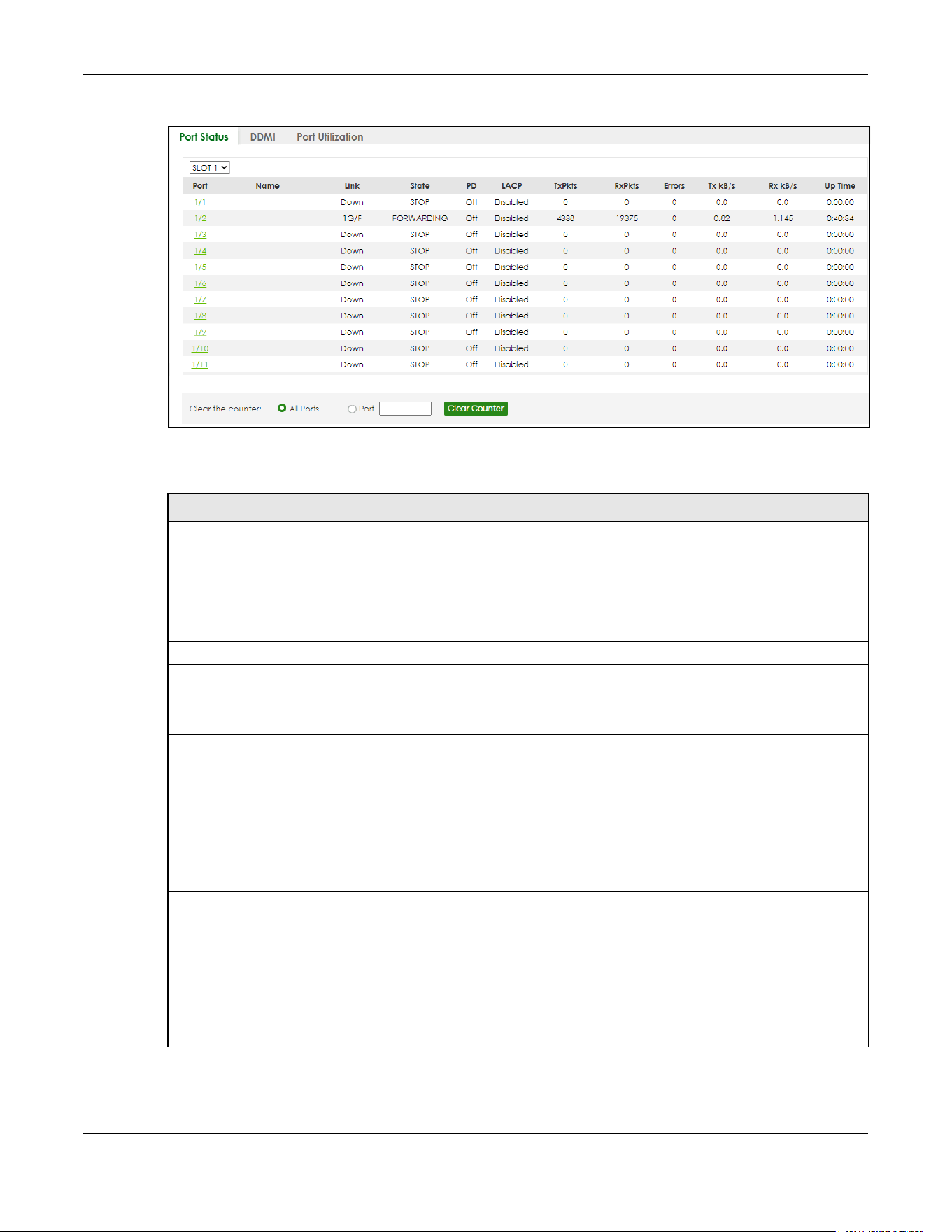
Chapter 15 Port Status
XGS2220 Series User’s Guide
141
Figure 95 MONITOR > Port Status > Port Status (Stacking Mode)
The following table describes the labels in this screen.
Table 41 MONITOR > Port Status > Port Status
LABEL DESCRIPTION
SLOT This field appears only in Stacking mode. Click the drop-down list to choose the slot number of
the Switch in a stack.
Port This identifies the Ethernet port. In Stacking mode, the first number represents the slot ID and the
second is the port number. Please note that the default stacking ports (the last two ports of your
Switch) cannot be configured. They are reserved for stacking only.
Click a port number to display the Port Details screen.
Name This is the name you assigned to this port in the PORT > Port Setup screen.
Link This field displays the speed (either 100M for 100 Mbps, 1G for 1 Gbps, 2.5G for 2.5 Gbps, 5G for 5
Gbps, or 10G for 10 Gbps) and the duplex (F for full duplex or H for half). It also shows the cable
type (Copper or Fiber) for the combo ports. This field displays Down if the port is not connected
to any device.
State If STP (Spanning Tree Protocol) is enabled, this field displays the STP state of the port.
If STP is disabled, this field displays FORWARDING if the link is up, otherwise, it displays STOP.
When LACP (Link Aggregation Control Protocol) and STP are in blocking state, it displays
BLOCKING.
PD For PoE models only.
This field displays whether or not a powered device (PD) is allowed to receive power from the
Switch on this port.
LACP This fields displays whether LACP (Link Aggregation Control Protocol) has been enabled on the
port.
TxPkts This field shows the number of transmitted frames on this port.
RxPkts This field shows the number of received frames on this port.
Errors This field shows the number of received errors on this port.
Tx kB/s This field shows the number of kilobytes per second transmitted on this port.
Rx kB/s This field shows the number of kilobytes per second received on this port.
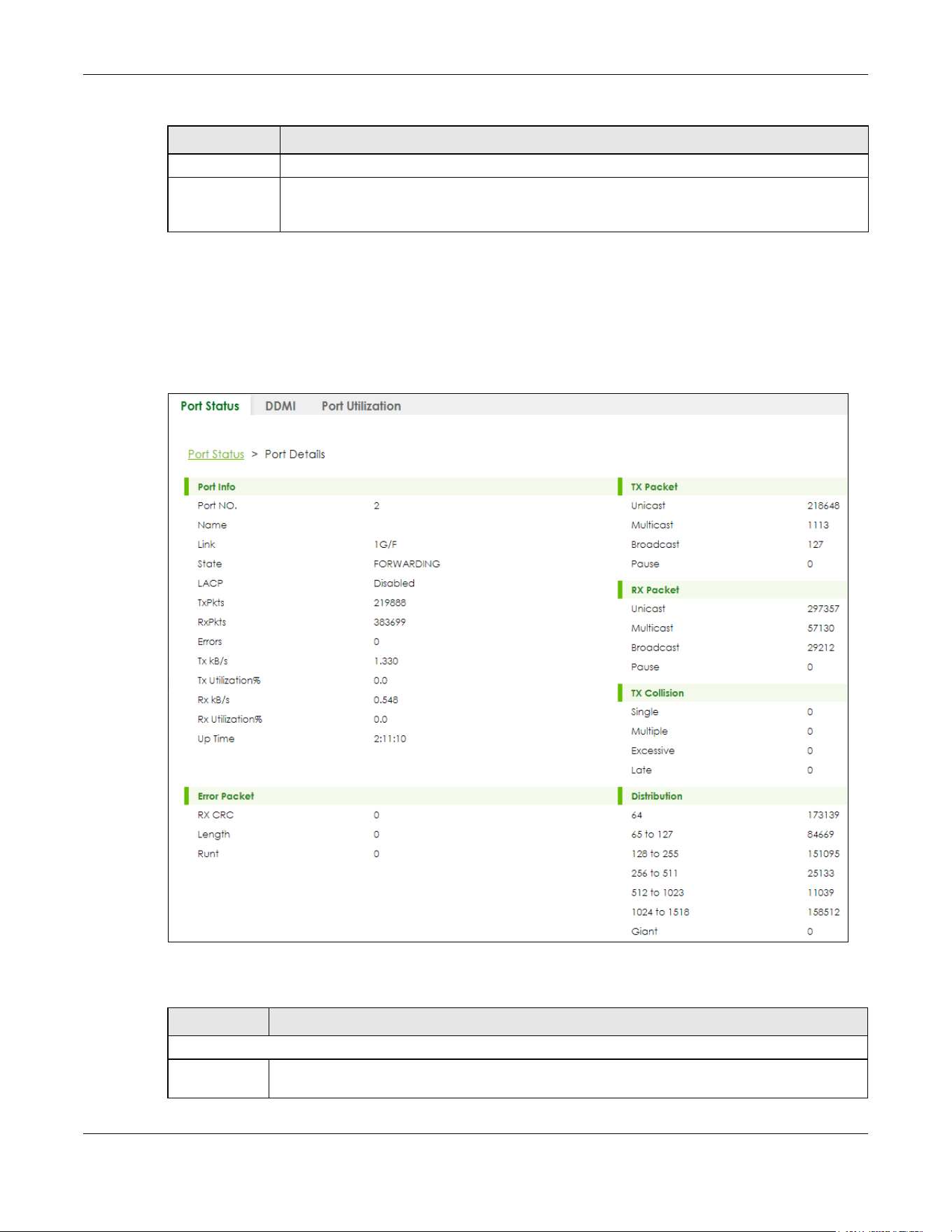
Chapter 15 Port Status
XGS2220 Series User’s Guide
142
15.1.1 Port Details
Click an index in the Port column in the MONITOR > Port Status > Port Status screen to display individual
port statistics. Use this screen to check status and detailed performance data about an individual port
on the Switch.
Figure 96 MONITOR > Port Status > Port Status > Port Details
The following table describes the labels in this screen.
Up Time This field shows the total amount of time in hours, minutes and seconds the port has been up.
Clear the
counter
Select Port, enter a port number and then click Clear Counter to erase the recorded statistical
information for that port, or select ALL Ports to clear statistics for all ports. In Stacking mode,
selecting ALL Ports clears statistics for all ports on this slot.
Table 41 MONITOR > Port Status > Port Status (continued)
LABEL DESCRIPTION
Table 42 MONITOR > Port Status > Port Status > Port Details
LABEL DESCRIPTION
Port Info
Port NO. This field displays the port number you are viewing. In Stacking mode, the first number represents
the slot and the second the port number.

Chapter 15 Port Status
XGS2220 Series User’s Guide
143
Name This field displays the name of the port.
Link This field displays the speed (either 100M for 100Mbps, 1G for 1 Gbps, 2.5G for 2.5 Gbps, 5G for 5
Gbps, or 10G for 10 Gbps) and the duplex (F for full duplex or H for half). It also shows the cable
type (Copper or Fiber) for the combo ports. This field displays Down if the port is not connected to
any device.
State If STP (Spanning Tree Protocol) is enabled, this field displays the STP state of the port.
If STP is disabled, this field displays FORWARDING if the link is up, otherwise, it displays STOP.
When LACP (Link Aggregation Control Protocol), STP, and dot1x are in blocking state, it displays
BLOCKING.
LACP This field shows if LACP is enabled on this port or not.
TxPkts This field shows the number of transmitted frames on this port.
RxPkts This field shows the number of received frames on this port.
Errors This field shows the number of received errors on this port.
Tx kB/s This field shows the number of kilobytes per second transmitted on this port.
Tx
Utilization%
This field shows the percentage of actual transmitted frames on this port as a percentage of the
Link speed.
Rx kB/s This field shows the number of kilobytes per second received on this port.
Rx
Utilization%
This field shows the percentage of actual received frames on this port as a percentage of the Link
speed.
Up Time This field shows the total amount of time the connection has been up.
TX Packet
The following fields display detailed information about packets transmitted.
Unicast This field shows the number of good unicast packets transmitted.
Multicast This field shows the number of good Multicast packets transmitted.
Broadcast This field shows the number of good broadcast packets transmitted.
Pause This field shows the number of 802.3x pause packets transmitted.
RX Packet
The following fields display detailed information about packets received.
Unicast This field shows the number of good unicast packets received.
Multicast This field shows the number of good Multicast packets received.
Broadcast This field shows the number of good broadcast packets received.
Pause This field shows the number of 802.3x pause packets received.
TX Collision
The following fields display information on collisions while transmitting.
Single This is a count of successfully transmitted packets for which transmission is inhibited by exactly one
collision.
Multiple This is a count of successfully transmitted packets for which transmission was inhibited by more
than one collision.
Excessive This is a count of packets for which transmission failed due to excessive collisions. Excessive
collision is defined as the number of maximum collisions before the retransmission count is reset.
Late This is the number of times a late collision is detected, that is, after 512 bits of the packets have
already been transmitted.
Table 42 MONITOR > Port Status > Port Status > Port Details (continued)
LABEL DESCRIPTION
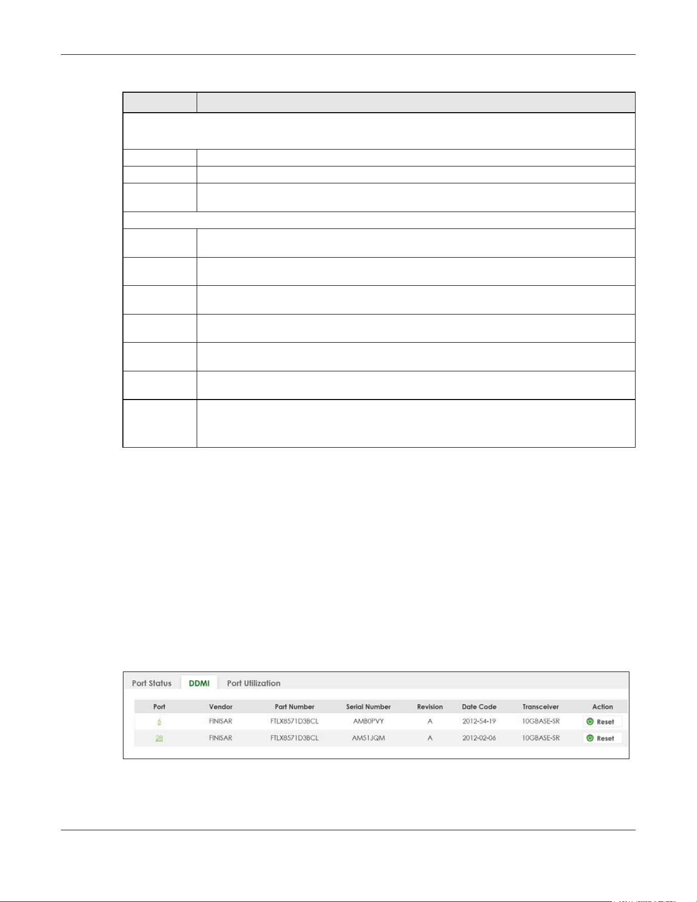
Chapter 15 Port Status
XGS2220 Series User’s Guide
144
15.2 DDMI
The optical SFP transceiver’s support for the Digital Diagnostics Monitoring Interface (DDMI) function lets
you monitor the transceiver’s parameters to perform component monitoring, fault isolation and failure
prediction tasks. This allows proactive, preventative network maintenance to help ensure service
continuity.
Use this screen to view the DDMI status of the Switch’s SFP transceivers. Click MONITOR > Port Status >
DDMI to see the following screen. Alternatively, click DASHBOARD from any Web Configurator screen
and then the Port Status link in the Quick Link section of the DASHBOARD screen to display the Port Status
screen and then click the DDMI link tab.
Figure 97 MONITOR > Port Status > DDMI (Standalone Mode)
Error Packet
The following fields display detailed information about packets received that were in error.
RX CRC This field shows the number of packets received with CRC (Cyclic Redundant Check) errors.
Length This field shows the number of packets received with a length that was out of range.
Runt This field shows the number of packets received that were too short (shorter than 64 octets),
including the ones with CRC errors.
Distribution
64 This field shows the number of packets (including bad packets) received that were 64 octets in
length.
65 to 127 This field shows the number of packets (including bad packets) received that were between 65
and 127 octets in length.
128 to 255 This field shows the number of packets (including bad packets) received that were between 128
and 255 octets in length.
256 to 511 This field shows the number of packets (including bad packets) received that were between 256
and 511 octets in length.
512 to
1023
This field shows the number of packets (including bad packets) received that were between 512
and 1023 octets in length.
1024 to
1518
This field shows the number of packets (including bad packets) received that were between 1024
and 1518 octets in length.
Giant This field shows the number of packets (including bad packets) received that were between 1519
octets and the maximum frame size.
The maximum frame size varies depending on your switch model.
Table 42 MONITOR > Port Status > Port Status > Port Details (continued)
LABEL DESCRIPTION

Chapter 15 Port Status
XGS2220 Series User’s Guide
145
Figure 98 MONITOR > Port Status > DDMI (Stacking Mode)
The following table describes the labels in this screen.
15.2.1 DDMI Details
Use this screen to view the real-time SFP (Small Form Factor Pluggable) transceiver information and
operating parameters on the SFP port. The parameters include, for example, transmitting and receiving
power, and module temperature.
Click an index in the Port column in the DDMI screen to view current transceivers’ status.
Table 43 MONITOR > Port Status > DDMI
LABEL DESCRIPTION
SLOT This field appears only in Stacking mode. Click the drop-down list to choose the slot number of
the Switch in a stack.
Port This identifies the SFP port. In Stacking mode, the first number represents the slot ID and the
second is the port number. Please note that the default stacking ports (the last four ports of your
Switch) cannot be configured. They are reserved for stacking only.
Click a port number to display the DDMI Details screen.
Vendor This displays the vendor name of the optical transceiver.
Part Number This displays the part number of the optical transceiver.
Serial Number This displays the serial number of the optical transceiver.
Revision This displays the revision number of the optical transceiver.
Date Code This displays the date when the optical transceiver was manufactured.
Transceiver This displays the type of optical transceiver installed in the SFP slot.
Action Click Reset when your SFP port encounters connection errors. For example, it can receive but
cannot transmit data. This Fiber Module Rescue function allows you to restart a fiber SFP
transceiver that is in error state without having to remove and reinsert the transceiver. The Switch
stops then re-supplies power on the specified SFP ports to restart it. After restarting an SFP port,
go to MONITOR > Port Status > Port Status to check the SFP port status. You can also check the
port LED on the Switch panel to see if the connection has recovered.
Note: Make sure an optical transceiver is correctly inserted into the SFP port.
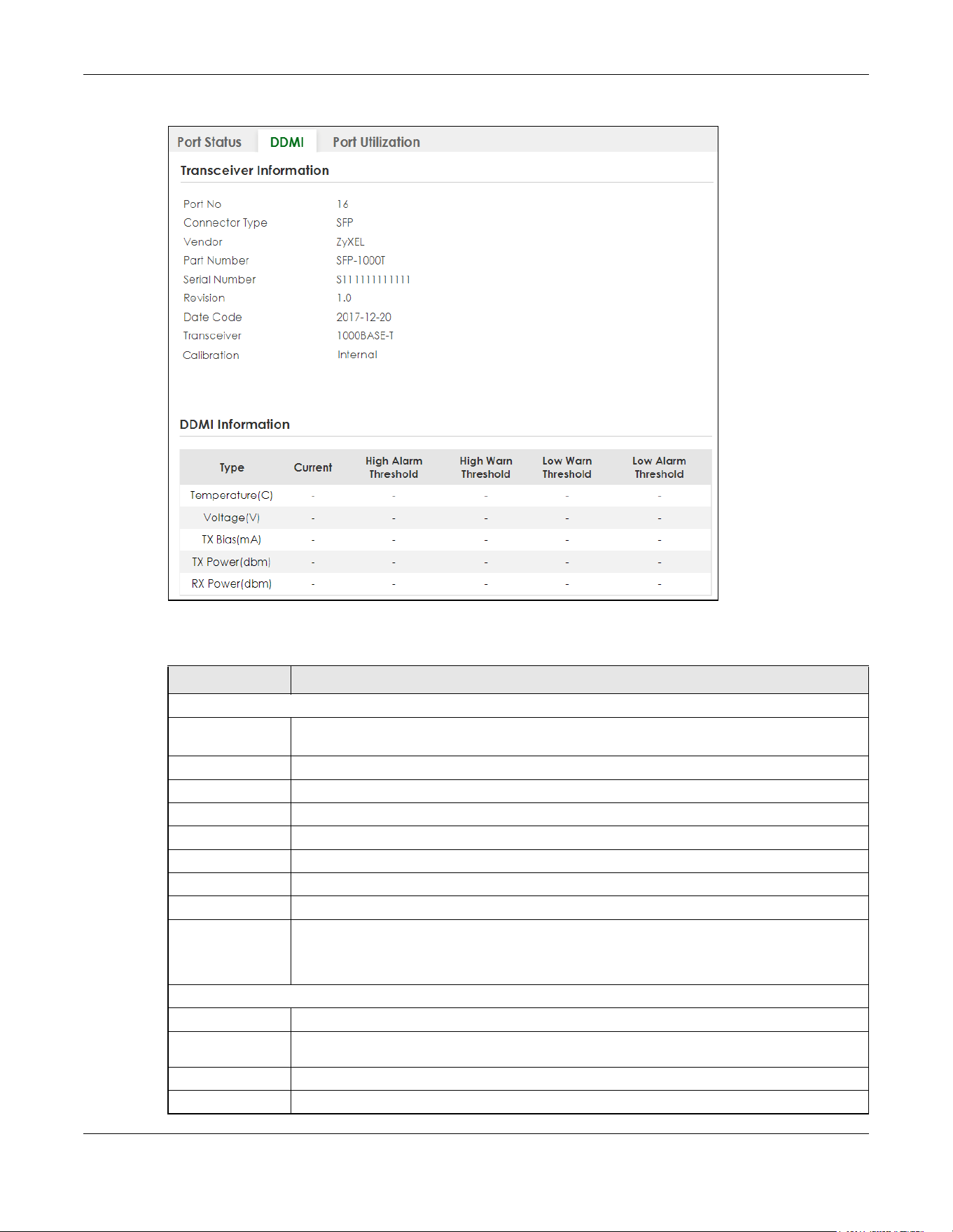
Chapter 15 Port Status
XGS2220 Series User’s Guide
146
Figure 99 MONITOR > Port Status > DDMI > DDMI Details
The following table describes the labels in this screen.
Table 44 MONITOR > Port Status > DDMI > DDMI Details
LABEL DESCRIPTION
Transceiver Information
Port No This identifies the SFP port. In Stacking mode, the first number represents the slot and the
second the port number.
Connector Type This displays the connector type of the optical transceiver.
Vendor This displays the vendor name of the optical transceiver.
Part Number This displays the part number of the optical transceiver.
Serial Number This displays the serial number of the optical transceiver.
Revision This displays the revision number of the optical transceiver.
Date Code This displays the date when the optical transceiver was manufactured.
Transceiver This displays details about the type of transceiver installed in the SFP slot.
Calibration This field is available only when an SFP transceiver is inserted into the SFP slot.
Internal displays if the measurement values are calibrated by the transceiver. External displays
if the measurement values are raw data which the Switch calibrates.
DDMI Information
Type This displays the DDMI parameter.
Temperature
(C/F)
This displays the temperature inside the SFP transceiver in degrees Celsius or Fahrenheit.
Voltage (V) This displays the level of voltage being supplied to the SFP transceiver.
TX Bias (mA) This displays the milliamps (mA) being supplied to the SFP transceiver’s Laser Diode Transmitter.
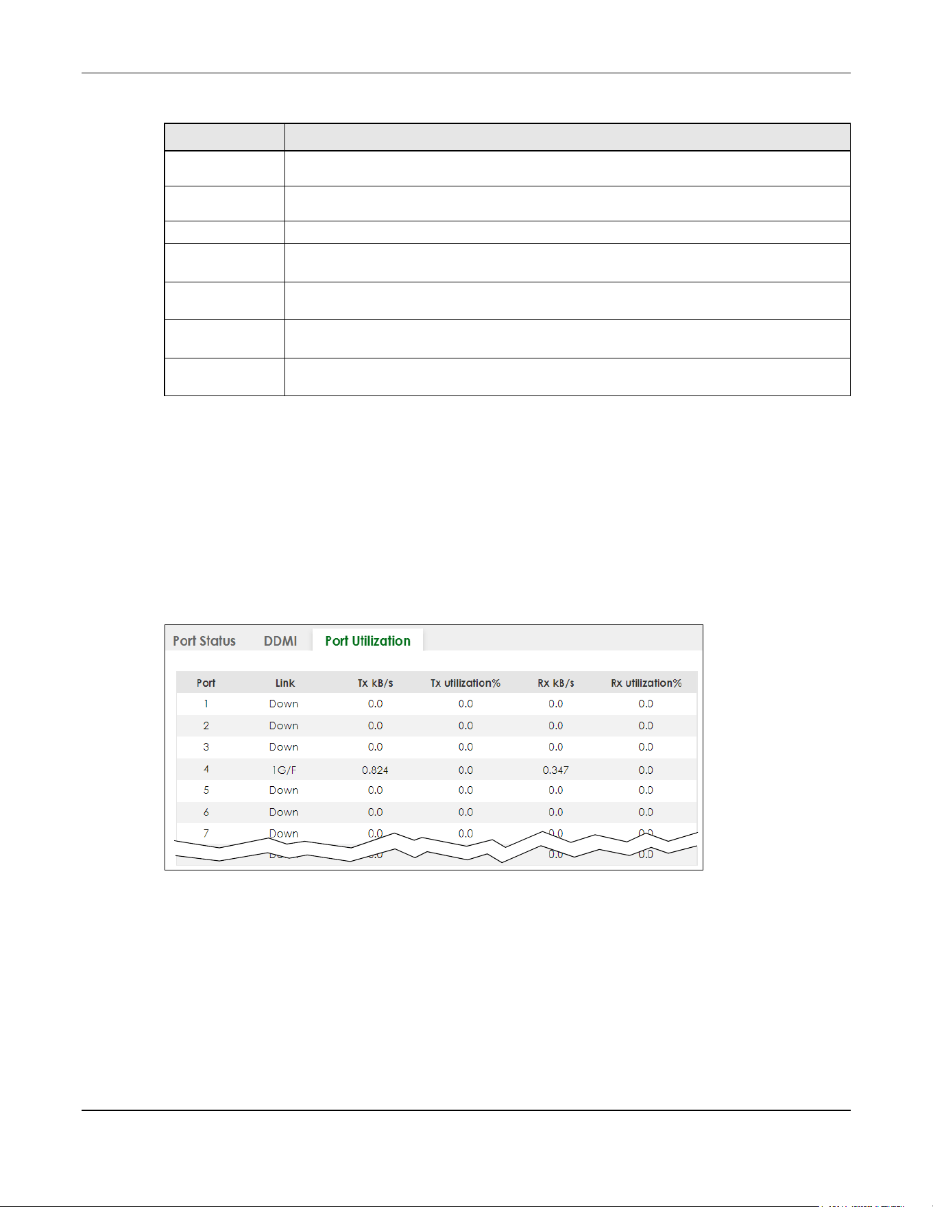
Chapter 15 Port Status
XGS2220 Series User’s Guide
147
15.3 Port Utilization
This screen displays the percentage of actual transmitted or received frames on a port as a percentage
of the Link speed. To view port utilization, click MONITOR > Port Status > Port Utilization to see the
following screen. Alternatively, click DASHBOARD from any Web Configurator screen and then the Port
Status link in the Quick Link section of the DASHBOARD screen to display the Port Status screen and then
click the Port Utilization link tab.
Figure 100 MONITOR > Port Status > Port Utilization (Standalone Mode)
TX Power
(dbm)
This displays the amount of power the SFP transceiver is transmitting.
RX Power
(dbm)
This displays the amount of power the SFP transceiver is receiving from the fiber cable.
Current This displays the current status for each monitored DDMI parameter.
High Alarm
Threshold
This displays the high value alarm threshold for each monitored DDMI parameter. An alarm
signal is reported to the Switch if the monitored DDMI parameter reaches this value.
High Warn
Threshold
This displays the high value warning threshold for each monitored DDMI parameter. A warning
signal is reported to the Switch if the monitored DDMI parameter reaches this value.
Low Warn
Threshold
This displays the low value warning threshold for each monitored DDMI parameter. A warning
signal is reported to the Switch if the monitored DDMI parameter reaches this value.
Low Alarm
Threshold
This displays the low value alarm threshold for each monitored DDMI parameter. An alarm
signal is reported to the Switch if the monitored DDMI parameter reaches this value.
Table 44 MONITOR > Port Status > DDMI > DDMI Details (continued)
LABEL DESCRIPTION

Chapter 15 Port Status
XGS2220 Series User’s Guide
148
Figure 101 MONITOR > Port Status > Port Utilization (Stacking Mode)
The following table describes the labels in this screen.
Table 45 MONITOR > Port Status > Port Utilization
LABEL DESCRIPTION
SLOT This field appears only in Stacking mode. Click the drop-down list to choose the slot number of the
Switch in a stack.
Port This identifies the Ethernet port. In Stacking mode, the first number represents the slot ID and the
second is the port number.
Link This field displays the speed (either 100M for 100Mbps, 1G for 1 Gbps, 2.5G for 2.5 Gbps, 5G for 5
Gbps, or 10G for 10 Gbps) and the duplex (F for full duplex or H for half). It also shows the cable
type (Copper or Fiber) for the combo ports. This field displays Down if the port is not connected to
any device.
Tx kB/s This field shows the transmission speed of data sent on this port in kilobytes per second.
Tx Utilization% This field shows the percentage of actual transmitted frames on this port as a percentage of the
Link speed.
Rx kB/s This field shows the transmission speed of data received on this port in kilobytes per second.
Rx Utilization% This field shows the percentage of actual received frames on this port as a percentage of the Link
speed.

Chapter 16 Routing Table
XGS2220 Series User’s Guide
149
CHAPTER 16
Routing Table
16.1 Routing Table Overview
This chapter introduces the IPv4/IPv6 routing tables.
The IPv4/IPv6 routing tables record routing information of the best path to destinations where packets
were forwarded. Use this table to check information like routing destination, gateway, interface IP
addresses, hop count, and routing methods.
16.1.1 What You Can Do
Use the IPv4 Routing Table screen (Section 16.2 on page 149) to view the Switch’s IPv4 routing table
information.
Use the IPv6 Routing Table screen (Section 16.3 on page 150) to view the Switch’s IPv6 routing table
information.
16.2 IPv4 Routing Table
Use this screen to view IPv4 routing table information. Click MONITOR > Routing Table > IPv4 Routing
Table in the navigation panel to display the screen as shown.
Figure 102 MONITOR > Routing Table > IPv4 Routing Table
The following table describes the labels in this screen.
Table 46 MONITOR > Routing Table > IPv4 Routing Table
LABEL DESCRIPTION
Index This field displays the index number.
Destination This field displays the destination IP routing domain.
Gateway This field displays the IP address of the gateway device.
Interface This field displays the IP address of the IPv4 Interface.
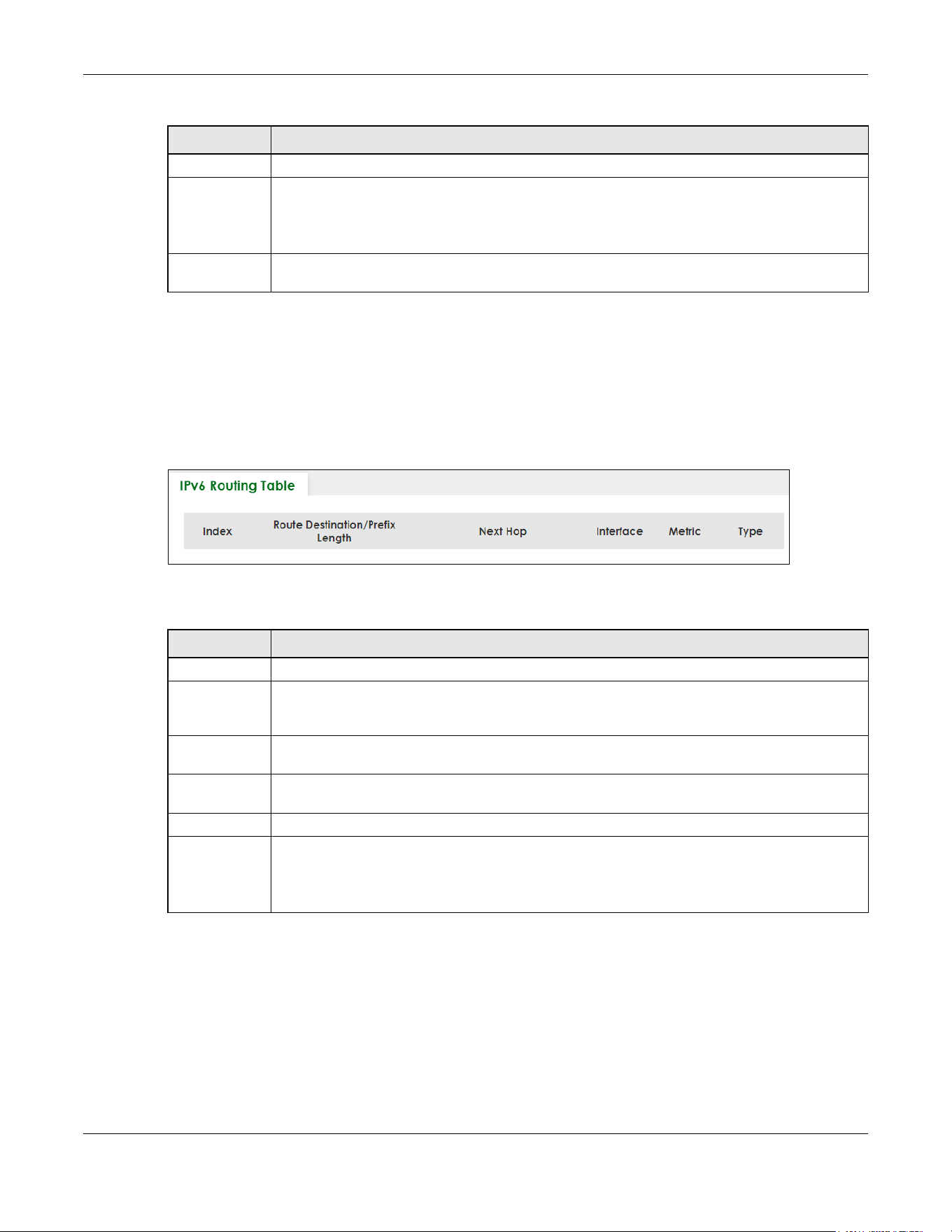
Chapter 16 Routing Table
XGS2220 Series User’s Guide
150
16.3 IPv6 Routing Table
Use this screen to view IPv6 routing table information. Click MONITOR > Routing Table > IPv6 Routing
Table in the navigation panel to display the screen as shown.
Figure 103 MONITOR > Routing Table > IPv6 Routing Table
The following table describes the labels in this screen.
Metric This field displays the cost of the route.
Type This field displays the method used to learn the route.
STATIC – added as a static entry.
LOCAL – added as a local interface entry.
Uptime This field displays how long the route has been running since the Switch learned the route and
added an entry in the routing table.
Table 46 MONITOR > Routing Table > IPv4 Routing Table (continued)
LABEL DESCRIPTION
Table 47 MONITOR > Routing Table > IPv6 Routing Table
LABEL DESCRIPTION
Index This field displays the index number.
Route
Destination/
Prefix Length
This field displays the IPv6 subnet prefix and prefix length of the final destination.
Next Hop This field displays the IPv6 address of the gateway that helps forward the packet to the
destination.
Interface This field displays the descriptive name of the IPv6 interface that is used to forward the packets to
the destination.
Metric This field displays the cost of the route.
Type This field displays the method used to learn the route.
STATIC – added as a static entry.
Connect – added as a local interface entry.
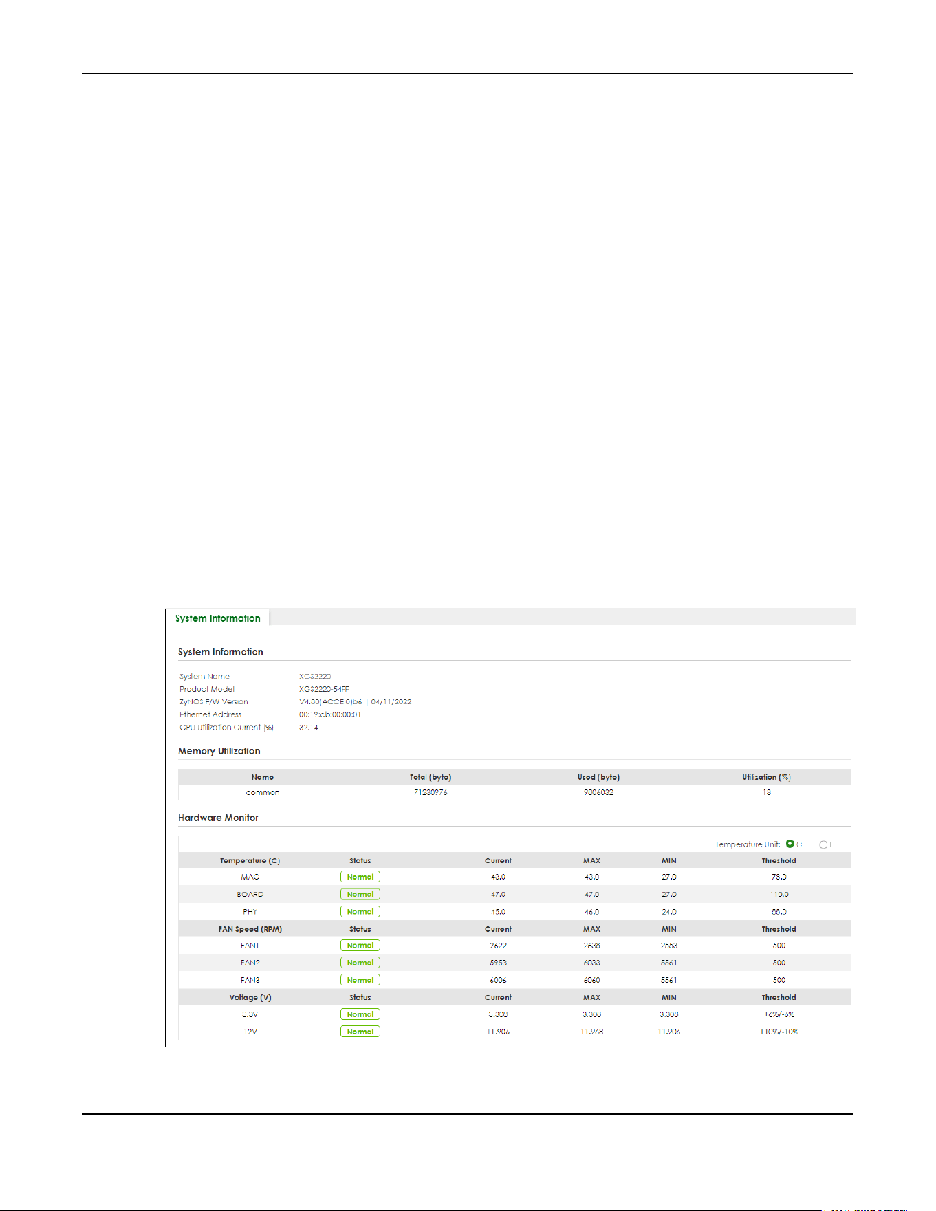
Chapter 17 System Information
XGS2220 Series User’s Guide
151
CHAPTER 17
System Information
17.0.1 What You Can Do
Use the System Information screen (Section 17.1 on page 151) to view general system information and
hardware status of the Switch.
Use the Hardware Monitor screen (Section 17.2 on page 153) to monitor and check the hardware status
of the Switch in Stacking mode.
17.1 System Information
In the navigation panel, click MONITOR > System Information to display the screen as shown. Use this
screen to view general system information.
Figure 104 MONITOR > System Information (Standalone Mode)

Chapter 17 System Information
XGS2220 Series User’s Guide
152
Figure 105 MONITOR > System Information (Stacking Mode)
The following table describes the labels in this screen.
Table 48 MONITOR > System Information
LABEL DESCRIPTION
System Information
System
Name
This displays the descriptive name of the Switch for identification purposes.
Product
Model
This displays the product model of the Switch. Use this information when searching for firmware
upgrade or looking for other support information in the website.
ZyNOS F/W
Version
This displays the version number of the Switch 's current firmware including the date created.
Ethernet
Address
This refers to the Ethernet MAC (Media Access Control) address of the Switch.
CPU
Utilization
Current (%)
This displays the current percentage of CPU utilization.
Memory Utilization
Memory utilization shows how much DRAM memory is available and in use. It also displays the current percentage
of memory utilization.
Name This displays the name of the memory pool.
Total (byte) This displays the total number of bytes in this memory pool.
Used (byte) This displays the number of bytes being used in this memory pool.
Utilization
(%)
This displays the percentage (%) of memory being used in this memory pool.
Hardware Monitor
Temperature
Unit
The Switch has temperature sensors that are capable of detecting and reporting if the
temperature rises above the threshold. You may choose the temperature unit (Centigrade or
Fahrenheit) in this field.
Temperature
(C/F)
MAC, BOARD, and PHY refer to the location of the temperature sensor on the Switch printed
circuit board.
Status This field displays Normal for temperatures below the threshold and Error for those above.
Current This shows the current temperature at this sensor.
MAX This field displays the maximum temperature measured at this sensor.
MIN This field displays the minimum temperature measured at this sensor.

Chapter 17 System Information
XGS2220 Series User’s Guide
153
17.2 Hardware Monitor (Stacking Mode)
This screen only appears when the Switch is in Stacking mode.
In the MONITOR > System Information screen, click an index of a Slot under Hardware Monitor to display
the screen as shown. Use this screen to view hardware information of a specific slot (Switch) in your
stacking system.
Threshold This field displays the upper temperature limit at this sensor.
Fan Speed
(RPM)
A properly functioning fan is an essential component (along with a sufficiently ventilated, cool
operating environment) in order for the device to stay within the temperature threshold. Each
fan has a sensor that is capable of detecting and reporting if the fan speed falls below the
threshold shown.
Status Normal indicates that this fan is functioning above the minimum speed. Error indicates that this
fan is functioning below the minimum speed.
Current This field displays this fan's current speed in Revolutions Per Minute (RPM).
MAX This field displays this fan's maximum speed measured in Revolutions Per Minute (RPM).
MIN This field displays this fan's minimum speed measured in Revolutions Per Minute (RPM). "<41" is
displayed for speeds too small to measure (under 2000 RPM).
Threshold This field displays the minimum speed at which a normal fan should work.
Voltage(V) The power supply for each voltage has a sensor that is capable of detecting and reporting if the
voltage falls out of the tolerance range.
Status Normal indicates that the voltage is within an acceptable operating range at this point;
otherwise Error is displayed.
Current This is the current voltage reading.
MAX This field displays the maximum voltage measured at this point.
MIN This field displays the minimum voltage measured at this point.
Threshold This field displays the percentage tolerance of the voltage with which the Switch still works.
Hardware Monitor (Stacking Mode)
Slot This number identifies the Switch in the stack. Click the number to see more detailed information
on the Switch.
Name This is the system name of the Switch in the stack.
Voltage This shows if the power supply voltage sensor is within normal tolerance range.
Temperature This shows if the temperature sensors on the Switch printed circuit board are within normal
tolerance range.
Fan This shows if the fan sensors are within normal tolerance range.
Power Supply This shows if the Switch is properly operating from the connected power source.
Table 48 MONITOR > System Information (continued)
LABEL DESCRIPTION

Chapter 17 System Information
XGS2220 Series User’s Guide
154
Figure 106 MONITOR > System Information > Hardware Monitor (Stacking Mode)
The following table describes the labels in this screen.
Table 49 MONITOR > System Information > Hardware Monitor (Stacking Mode)
LABEL DESCRIPTION
This displays the slot ID of the Switch in the stacking system.
Temperature
Unit
The Switch has temperature sensors that are capable of detecting and reporting if the
temperature rises above the threshold. You may choose the temperature unit: C (Centigrade) or
F (Fahrenheit) in this field.
Temperature
(C/F)
CPU/MAC, BOARD, and PHY refer to the location of the temperature sensors on the Switch
printed circuit board. The first number represents the slot ID.
Status This field displays Normal for temperatures below the threshold and Error for those above.
Current This shows the current temperature at this sensor.
MAX This field displays the maximum temperature measured at this sensor.
MIN This field displays the minimum temperature measured at this sensor.
Threshold This field displays the upper temperature limit at this sensor.
Fan Speed
(RPM)
A properly functioning fan is an essential component (along with a sufficiently ventilated, cool
operating environment) in order for the device to stay within the temperature threshold. Each fan
has a sensor that is capable of detecting and reporting if the fan speed falls below the threshold
shown. The first number represents the slot ID.
Status Normal indicates that this fan is functioning above the minimum speed. Error indicates that this
fan is functioning below the minimum speed.
Current This field displays this fan's current speed in Revolutions Per Minute (RPM).
MAX This field displays this fan's maximum speed measured in Revolutions Per Minute (RPM).
MIN This field displays this fan's minimum speed measured in Revolutions Per Minute (RPM). "<41" is
displayed for speeds too small to measure (under 2000 RPM).
Threshold This field displays the minimum speed at which a normal fan should work.
Voltage (V) The power supply for each voltage has a sensor that is capable of detecting and reporting if the
voltage falls out of the tolerance range. The first number represents the slot ID.
Status Normal indicates that the voltage is within an acceptable operating range at this point;
otherwise Error is displayed.
Current This is the current voltage reading.

Chapter 17 System Information
XGS2220 Series User’s Guide
155
MAX This field displays the maximum voltage measured at this point.
MIN This field displays the minimum voltage measured at this point.
Threshold This field displays the percentage tolerance of the voltage with which the Switch still works.
Table 49 MONITOR > System Information > Hardware Monitor (Stacking Mode) (continued)
LABEL DESCRIPTION
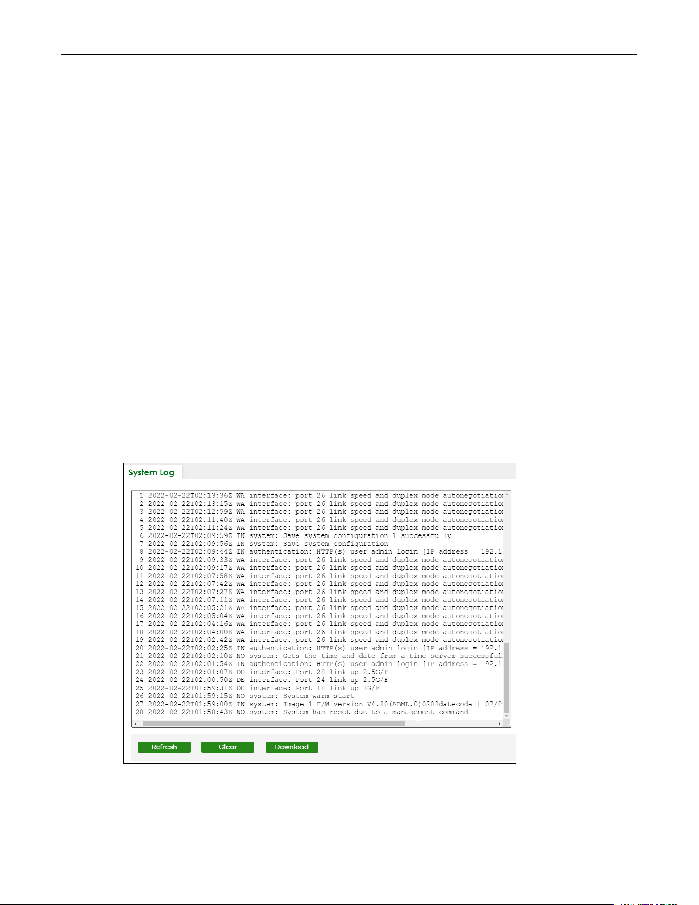
Chapter 18 System Log
XGS2220 Series User’s Guide
156
CHAPTER 18
System Log
18.1 System Log Overview
A log message stores the system history information for viewing.
18.2 System Log
Click MONITOR > System Log in the navigation panel to open this screen. Use this screen to check
current system logs.
Note: When a log reaches the maximum number of log messages, new log messages
automatically overwrite existing log messages, starting with the oldest existing log
message first.
Figure 107 MONITOR > System Log
The summary table shows the time the log message was recorded and the reason the log message was
generated. Click Refresh to update this screen. Click Clear to clear the whole log, regardless of what is
currently displayed on the screen. Click Download to save the log to your computer.

XGS2220 Series User’s Guide
157
CHAPTER 19
SYSTEM
The following chapters introduces the configurations of the links under the SYSTEM navigation panel.
Quick links to chapters:
• Cloud Management
• General Setup
• Hardware Monitor Setup
• Interface Setup
• IP Setup
• IPv6
• Logins
• SNMP
• Stacking
• Switch Setup
• Syslog Setup
• Time Range

Chapter 20 Cloud Management
XGS2220 Series User’s Guide
158
CHAPTER 20
Cloud Management
20.1 Cloud Management Overview
The Zyxel Nebula Control Center (NCC) is a cloud-based network management system that allows you
to remotely manage and monitor Zyxel Nebula APs, Ethernet switches and security gateways.
The Switch is managed and provisioned automatically by the NCC (Nebula Control Center) when:
• It is connected to the Internet.
• The Nebula Control Center (NCC) Discovery feature is enabled.
• It has been registered in the NCC.
20.2 Nebula Center Control Discovery
Click SYSTEM > Cloud Management to display this screen.
Figure 108 SYSTEM > Cloud Management

Chapter 20 Cloud Management
XGS2220 Series User’s Guide
159
The following table describes the labels in this screen.
Cloud Management Mode
Enable the switch button to turn on NCC discovery on the Switch. If the Switch has Internet access and
has been registered on the NCC, it will automatically go into cloud management mode. Follow the
steps to register your Switch on NCC:
1 Download the Nebula Mobile App
First, download the app from the Google Play store for Android devices or the App Store for iOS devices
and create an organization and site.
You can scan an app store QR code to open the app installation page on the app store.
2 Scan the Device QR code
The Register Device QR code in this screen contains the Switch’s serial number and the registration MAC
address for handy NCC registration of the Switch using the Nebula Mobile app.
Follow the wizard in the Nebula Mobile app to scan the QR code to register the Switch on NCC and add
the Switch into a site.
If Nebula Control Center (NCC) Discovery is disabled, the Switch will NOT discover the NCC and remain
in Standalone mode.
Table 50 SYSTEM > Cloud Management
LABEL DESCRIPTION
Nebula Control
Center (NCC)
Discovery
Enable the switch button to turn on Nebula Control Center (NCC) discovery on the Switch.
This field displays:
• The Switch Internet connection status.
• The connection status between the Switch and NCC.
• The Switch registration status on NCC.
To pass your Switch management to NCC, first make sure your Switch is connected to the
Internet. Then go to NCC and register your Switch.
1. Internet
Green – The Switch is connected to the Internet.
Orange – The Switch is not connected to the Internet.
2. Nebula
Green – The Switch is connected to NCC.
Orange – The Switch is not connected to NCC.
3. Registration
Green – The Switch is registered on NCC.
Gray – The Switch is not registered on NCC.
Note: All circles will gray out if you disable Nebula Discovery.
Connection
Status
This table displays the NCC connection status information.
Use status logs in the Internet, Nebula, and Registration fields for connection troubleshooting.

Chapter 21 General Setup
XGS2220 Series User’s Guide
160
CHAPTER 21
General Setup
21.1 General Setup
Use this screen to configure general settings such as the system name and time. Click SYSTEM > General
Setup in the navigation panel to display the screen as shown.
Figure 109 SYSTEM > General Setup
Note: The input string of any field in this screen should not contain [ ? ], [ | ], [ ' ], [ " ], or [ , ].
The following table describes the labels in this screen.
Table 51 SYSTEM > General Setup
LABEL DESCRIPTION
System Name Choose a descriptive name for identification purposes. This name consists of up to 64 printable
ASCII characters; spaces are allowed.
Location Enter the geographic location of your Switch. You can use up to 128 printable ASCII
characters; spaces are allowed.
Contact Person's
Name
Enter the name of the person in charge of this Switch. You can use up to 32 printable ASCII
characters; spaces are allowed.

Chapter 21 General Setup
XGS2220 Series User’s Guide
161
Use Time Server
when Bootup
Enter the time service protocol that your time server uses. Not all time servers support all
protocols, so you may have to use trial and error to find a protocol that works. The main
differences between them are the time format.
When you select the Daytime (RFC-867) format, the Switch displays the day, month, year and
time with no time zone adjustment. When you use this format it is recommended that you use a
Daytime timeserver within your geographical time zone.
Time (RFC-868) format displays a 4-byte integer giving the total number of seconds since 1970/
1/1 at 00:00:00.
NTP (RFC-1305) is similar to Time (RFC-868).
None is the default value. Enter the time manually. Each time you turn on the Switch, the time
and date will be reset to 2022-01-01 00:00:00.
Time Server IP
Address
Enter the IP address or domain name of your timeserver. The Switch searches for the timeserver
for up to 60 seconds.
Time Server Sync
Interval
Enter the period in minutes between each time server synchronization. The Switch checks the
time server after every synchronization interval.
Current Time This field displays the time you open this menu (or refresh the menu).
New Time
(hh:mm:ss)
Enter the new time in hour, minute and second format. The new time then appears in the
Current Time field after you click Apply.
Current Date This field displays the date you open this menu.
New Date (yyyy-
mm-dd)
Enter the new date in year, month and day format. The new date then appears in the Current
Date field after you click Apply.
Time Zone Select the time difference between UTC (Universal Time Coordinated, formerly known as GMT,
Greenwich Mean Time) and your time zone from the drop-down list box.
Daylight Saving
Time
Daylight saving is a period from late spring to early fall when many countries set their clocks
ahead of normal local time by one hour to give more daytime light in the evening.
Enable the switch button if you use Daylight Saving Time.
Start Date Configure the day and time when Daylight Saving Time starts if you selected Daylight Saving
Time. The time is displayed in the 24 hour format. Here are a couple of examples:
Daylight Saving Time starts in most parts of the United States on the second Sunday of March.
Each time zone in the United States starts using Daylight Saving Time at 2 A.M. local time. So in
the United States you would select Second, Sunday, March and 2:00.
Daylight Saving Time starts in the European Union on the last Sunday of March. All of the time
zones in the European Union start using Daylight Saving Time at the same moment (1 A.M. GMT
or UTC). So in the European Union you would select Last, Sunday, March and the last field
depends on your time zone. In Germany for instance, you would select 2:00 because
Germany's time zone is one hour ahead of GMT or UTC (GMT+1).
End Date Configure the day and time when Daylight Saving Time ends if you selected Daylight Saving
Time. The time field uses the 24 hour format. Here are a couple of examples:
Daylight Saving Time ends in the United States on the first Sunday of November. Each time
zone in the United States stops using Daylight Saving Time at 2 A.M. local time. So in the United
States you would select First, Sunday, November and 2:00.
Daylight Saving Time ends in the European Union on the last Sunday of October. All of the time
zones in the European Union stop using Daylight Saving Time at the same moment (1 A.M. GMT
or UTC). So in the European Union you would select Last, Sunday, October and the last field
depends on your time zone. In Germany for instance, you would select 2:00 because
Germany's time zone is one hour ahead of GMT or UTC (GMT+1).
Table 51 SYSTEM > General Setup (continued)
LABEL DESCRIPTION

Chapter 21 General Setup
XGS2220 Series User’s Guide
162
21.2 Hardware Monitor Setup
This section introduces Fan Control for the temperature of the SFP transceiver inserted in the Switch.
When the SFP transceiver temperature exceeds the temperature threshold (see your transceiver
documentation), the Switch automatically turns on the fans with maximum fan speed to cool down the
system.
The fans do not automatically turn off after the SFP transceiver temperature returns below threshold. To
turn off the fans, you have to temporarily disable SFP Detect or reboot the Switch.
Click SYSTEM > Hardware Monitor Setup to display the screen as shown below.
Note: The SFP Detect feature only functions if at least one of your SFP transceiver(s) support
DDMI (Digital Diagnostic Monitoring Interface). See the transceiver documentation.
Figure 110 SYSTEM > Hardware Monitor Setup
The following table describes the labels in this screen.
Apply Click Apply to save your changes to the Switch’s run-time memory. The Switch loses these
changes if it is turned off or loses power, so use the Save link on the top navigation panel to
save your changes to the non-volatile memory when you are done configuring.
Cancel Click Cancel to begin configuring this screen afresh.
Table 51 SYSTEM > General Setup (continued)
LABEL DESCRIPTION
Table 52 SYSTEM > Hardware Monitor Setup
LABEL DESCRIPTION
Fan Control
SFP Detect Enable the switch button to enable SFP Detect on the Switch.
Apply Click Apply to save your changes to the Switch’s run-time memory. The Switch loses these
changes if it is turned off or loses power, so use the Save link on the top navigation panel to save
your changes to the non-volatile memory when you are done configuring.
Cancel Click Cancel to begin configuring this screen afresh.

Chapter 21 General Setup
XGS2220 Series User’s Guide
163
You will see SFP warning icons next to the FANs in the MONITOR > System Information screen when SFP
Detect has triggered the fans.
Figure 111 Hardware Monitor: SFP Module Temperature Warning
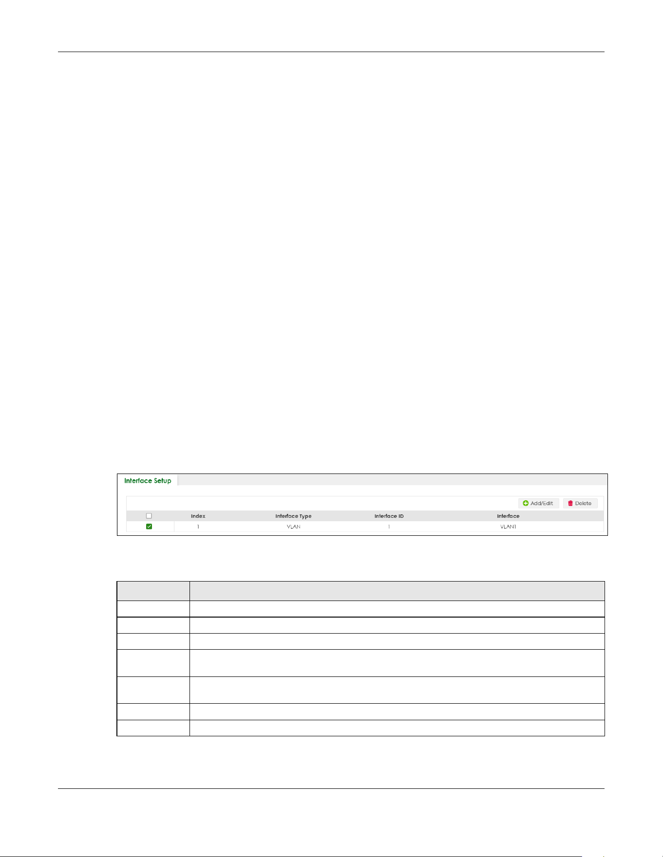
Chapter 22 Interface Setup
XGS2220 Series User’s Guide
164
CHAPTER 22
Interface Setup
22.1 Interface Setup Overview
This chapter shows you how to create virtual interfaces for interface-based configurations. An IPv6
address is configured on a per-interface basis. The interface can be a physical interface (for example,
an Ethernet port) or a virtual interface (for example, a VLAN).
22.2 Interface Setup
Use this screen to view and set IPv6 interfaces on which you can configure an IPv6 address to access
and manage the Switch.
The interfaces you create here will only take effect after you configure them in the SYSTEM > IPv6
screens.
Click SYSTEM > Interface Setup in the navigation panel to display the configuration screen.
Figure 112 SYSTEM > Interface Setup
The following table describes the labels in this screen.
Table 53 SYSTEM > Interface Setup
LABEL DESCRIPTION
Index This field displays the index number of an entry.
Interface Type This field displays the type of interface.
Interface ID This field displays the identification number of the interface.
Interface This field displays the interface’s descriptive name which is generated automatically by the
Switch. The name is from a combination of the interface type and ID number.
Select an entry’s check box to select a specific entry. Otherwise, select the check box in the
table heading row to select all entries.
Add/Edit Click Add/Edit to add a new interface or edit a selected one.
Delete Click Delete to remove the selected interfaces.
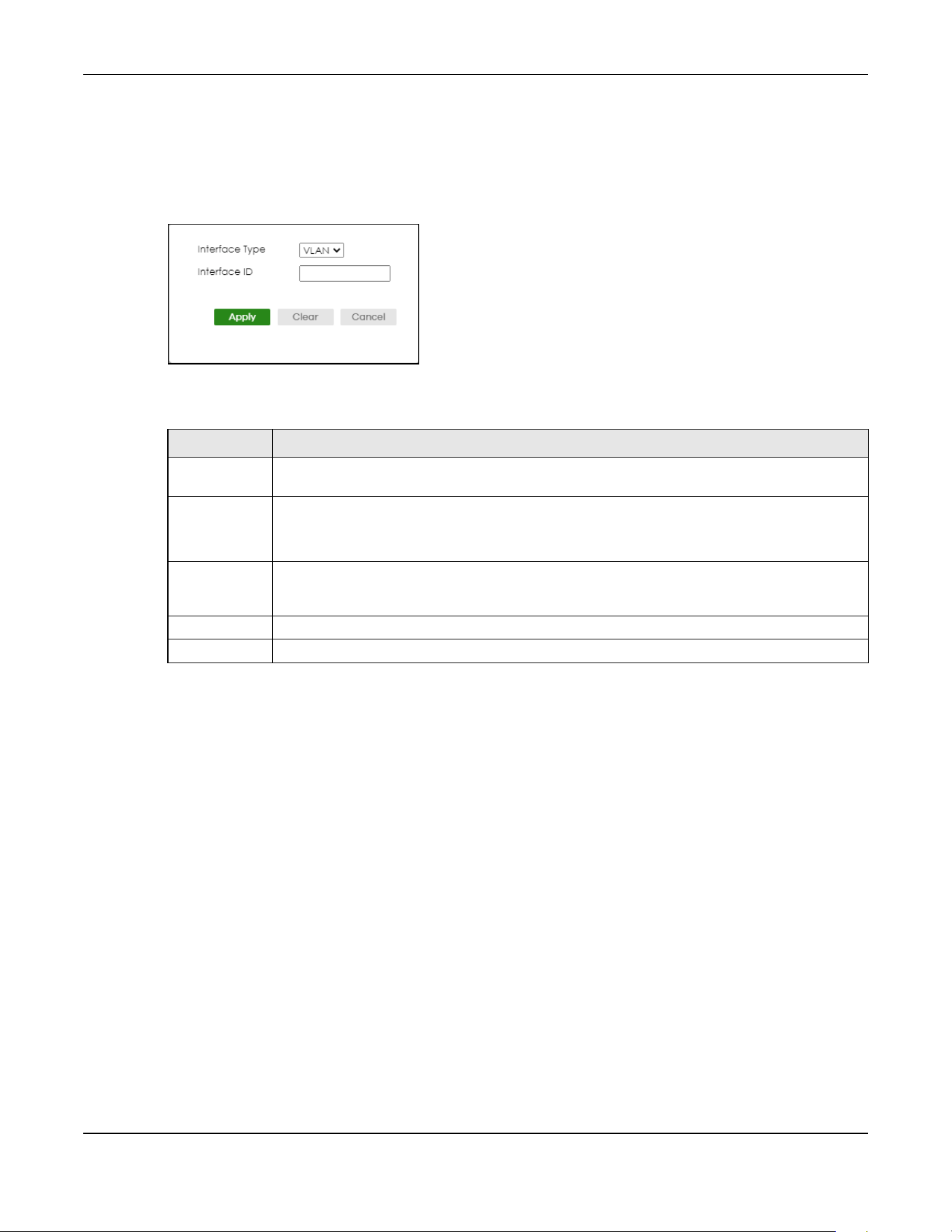
Chapter 22 Interface Setup
XGS2220 Series User’s Guide
165
22.2.1 Add/Edit Interfaces
Click Add/Edit, or select an entry and click Add/Edit in the SYSTEM > Interface Setup screen to display
the configuration screen.
Figure 113 SYSTEM > Interface Setup > Add/Edit
The following table describes the labels in this screen.
Table 54 SYSTEM > Interface Setup > Add/Edit
LABEL DESCRIPTION
Interface Type Select the type of IPv6 interface for which you want to configure. The Switch supports the VLAN
interface type for IPv6 at the time of writing.
Interface ID Specify a unique identification number (from 1 to 4094) for the interface.
To have IPv6 function properly, you should configure a static VLAN with the same ID number in the
SWITCHING > VLAN screens.
Apply Click Apply to save your changes to the Switch’s run-time memory. The Switch loses these
changes if it is turned off or loses power, so use the Save link on the top navigation panel to save
your changes to the non-volatile memory when you are done configuring.
Clear Click Clear to clear the fields to the factory defaults.
Cancel Click Cancel to not save the configuration you make and return to the last screen.

Chapter 23 IP Setup
XGS2220 Series User’s Guide
166
CHAPTER 23
IP Setup
23.1 IP Setup Overview
This chapter shows you how to configure IP settings and set up IP interfaces on the Switch using the IP
Setup screens.
23.1.1 What You Can Do
• Use the IP Status screen (Section 23.2 on page 167) to view the current IP interfaces and DNS server
settings on the Switch.
• Use the IP Setup screen (Section 23.3 on page 169) to configure the default gateway device, the
default domain name server and add IP domains.
• Use the Network Proxy Configuration screen (Section 23.4 on page 171) to configure network proxy
configurations.
23.1.2 IP Interfaces
The Switch needs an IP address for it to be managed over the network. When the Switch (in Standalone
mode) fails to obtain an IP address from a DHCP server, the default static IP address 192.168.1.1 will be
automatically added and used as the Switch’s management IP address. The subnet mask specifies the
network number portion of an IP address. The factory default subnet mask is 255.255.255.0.
On the Switch, an IP address is not bound to any physical ports. Since each IP address on the Switch
must be in a separate subnet, the configured IP address is also known as IP interface (or routing
domain). In addition, this allows routing between subnets based on the IP address without additional
routers.
You can configure multiple routing domains on the same VLAN as long as the IP address ranges for the
domains do not overlap. To change the IP address of the Switch in a routing domain, simply add a new
routing domain entry with a different IP address in the same subnet.
You can configure up to 128 IP domains which are used to access and manage the Switch from the
ports belonging to the pre-defined VLANs.
Note: You must configure a VLAN first. Each VLAN can have multiple management IP
addresses, and you can log into the Switch through different management IP
addresses simultaneously.
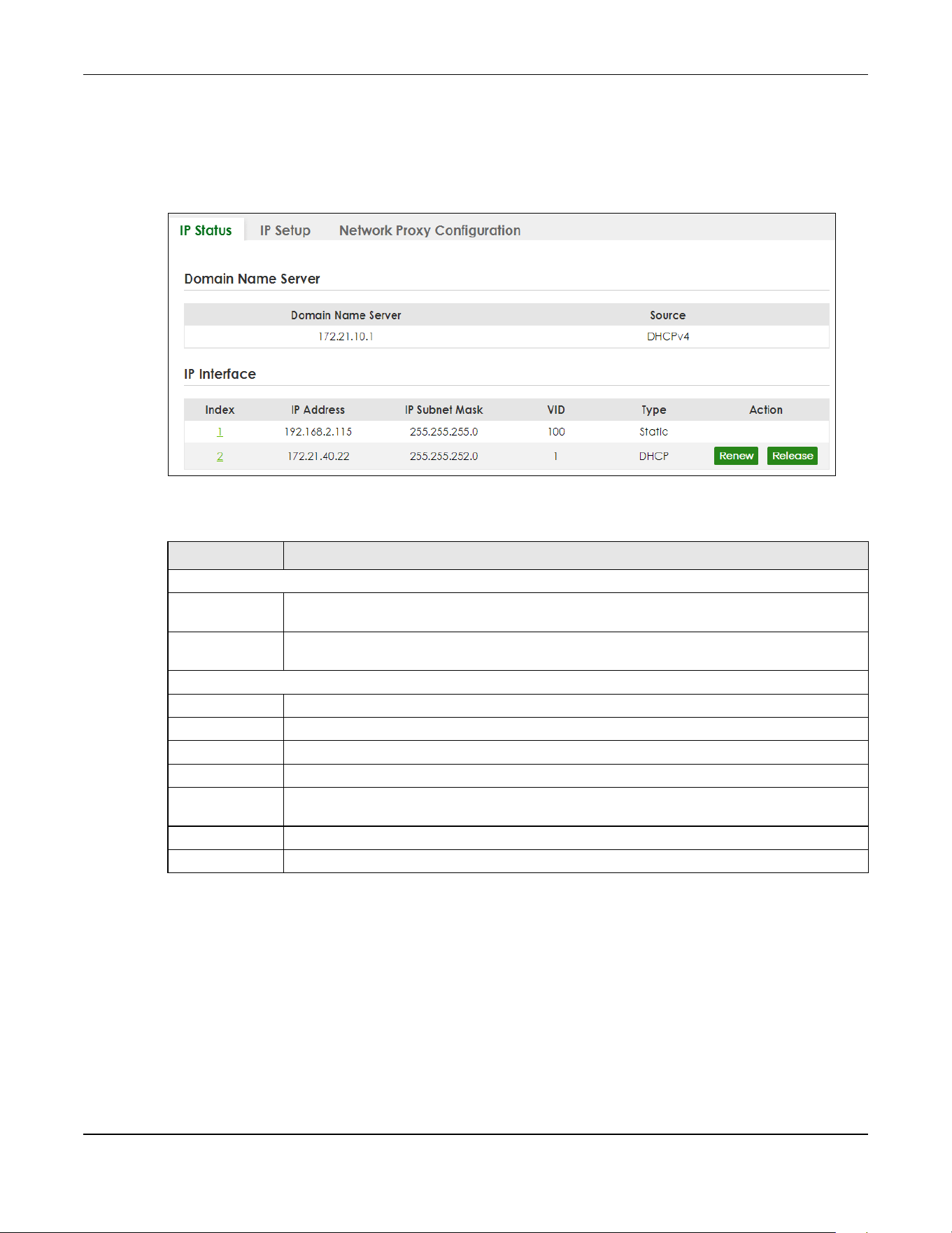
Chapter 23 IP Setup
XGS2220 Series User’s Guide
167
23.2 IP Status
Click SYSTEM > IP Setup > IP Status to display the screen as shown.
Figure 114 SYSTEM > IP Setup > IP Status
The following table describes the labels in this screen.
23.2.1 IP Status Details
Use this screen to view IP status details. Click a number in the Index column in the SYSTEM > IP Setup > IP
Status screen to display the screen as shown next.
Table 55 SYSTEM > IP Setup > IP Status
LABEL DESCRIPTION
Domain Name Server
Domain Name
Server
This field displays the IP address of the DNS server.
Source This field displays whether the DNS server address is configured manually (Static) or obtained
automatically using DHCPv4.
IP Interface
Index This field displays the index number of an entry.
IP Address This field displays the IP address of the Switch in the IP domain.
IP Subnet Mask This field displays the subnet mask of the Switch in the IP domain.
VID This field displays the VLAN identification number of the IP domain on the Switch.
Type This shows whether this IP address is dynamically assigned from a DHCP server (DHCP) or
manually assigned (Static).
Renew Click this to renew the dynamic IP address.
Release Click this to release the dynamic IP address.
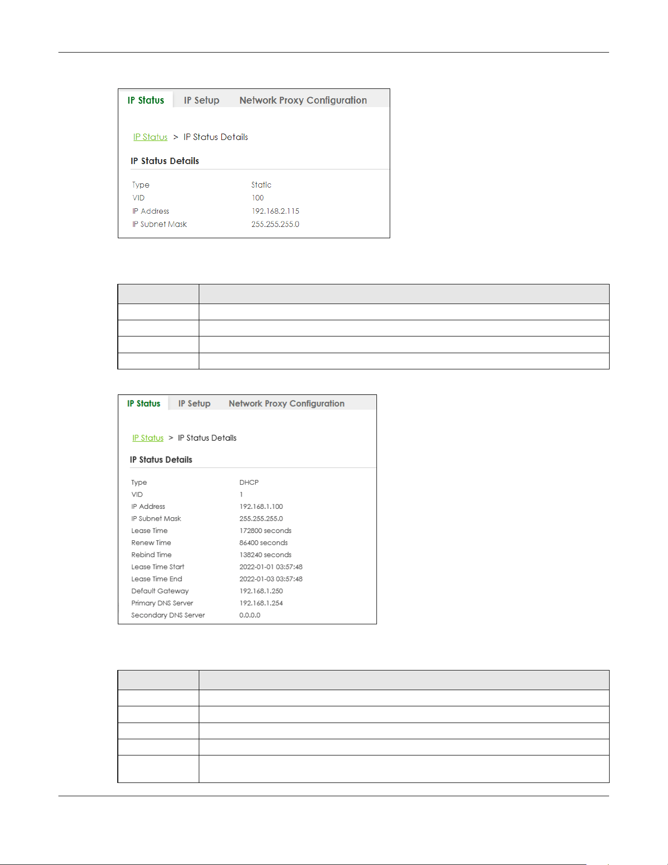
Chapter 23 IP Setup
XGS2220 Series User’s Guide
168
Figure 115 SYSTEM > IP Setup > IP Status > IP Status Details: Static
The following table describes the labels in this screen.
Figure 116 SYSTEM > IP Setup > IP Status > IP Status Details: DHCP
The following table describes the labels in this screen.
Table 56 SYSTEM > IP Setup > IP Status > IP Status Details: Static
LABEL DESCRIPTION
Type This shows the IP address is manually assigned (Static).
VID This is the VLAN identification number to which an IP routing domain belongs.
IP Address This is the IP address of your Switch in dotted decimal notation for example 192.168.1.1.
IP Subnet Mask This is the IP subnet mask of your Switch in dotted decimal notation for example 255.255.255.0.
Table 57 SYSTEM > IP Setup > IP Status > IP Status Details: DHCP
LABEL DESCRIPTION
Type This shows the IP address is dynamically assigned from a DHCP server (DHCP).
VID This is the VLAN identification number to which an IP routing domain belongs.
IP Address This is the IP address of your Switch in dotted decimal notation for example 192.168.1.1.
IP Subnet Mask This is the IP subnet mask of your Switch in dotted decimal notation for example 255.255.255.0.
Lease Time This displays the length of time in seconds that this interface can use the current dynamic IP
address from the DHCP server.

Chapter 23 IP Setup
XGS2220 Series User’s Guide
169
23.3 IP Setup
Use this screen to configure the default gateway device, the default domain name server and add IP
domains. Click SYSTEM > IP Setup > IP Setup in the navigation panel to display the screen as shown.
Note: The Switch allows you to set a static IP interface in the same subnet that already has a
DHCP-assigned IP interface on the Switch. The Switch will use the static IP you set and
the DHCP-assigned IP will be set to 0.0.0.0.
Figure 117 SYSTEM > IP Setup > IP Setup
The following table describes the labels in this screen.
Renew Time This displays the length of time from the lease start that the Switch will request to renew its
current dynamic IP address from the DHCP server.
Rebind Time This displays the length of time from the lease start that the Switch will request to get any
dynamic IP address from the DHCP server.
Lease Time Start This displays the date and time that the current dynamic IP address assignment from the DHCP
server began. You should configure date and time in SYSTEM > General Setup.
Lease Time End This displays the date and time that the current dynamic IP address assignment from the DHCP
server will end. You should configure date and time in SYSTEM > General Setup.
Default
Gateway
This displays the IP address of the default gateway assigned by the DHCP server. 0.0.0.0 means
no gateway is assigned.
Primary /
Secondary DNS
Server
This displays the IP address of the primary and secondary DNS servers assigned by the DHCP
server. 0.0.0.0 means no DNS server is assigned.
Table 57 SYSTEM > IP Setup > IP Status > IP Status Details: DHCP (continued)
LABEL DESCRIPTION
Table 58 SYSTEM > IP Setup > IP Setup
LABEL DESCRIPTION
IP Setup
Default
Gateway
Type the IP address of the default outgoing gateway in dotted decimal notation, for example
192.168.1.254.
Domain Name
Server 1/2
Enter a domain name server IPv4 address in order to be able to use a domain name instead of
an IP address.
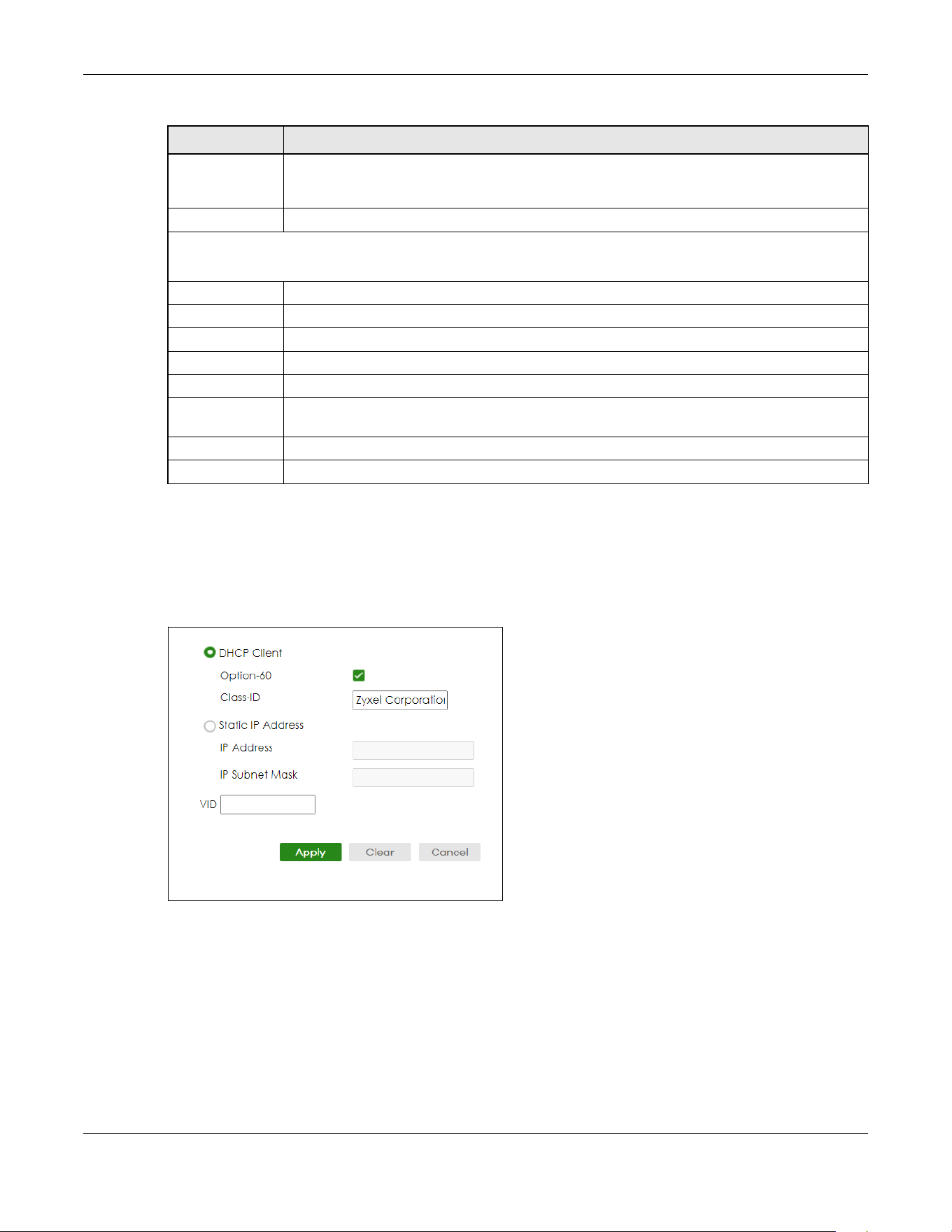
Chapter 23 IP Setup
XGS2220 Series User’s Guide
170
23.3.1 Add/Edit IP Interfaces
Use this screen to add or edit IP interfaces. Click Add/Edit, or select an entry and click Add/Edit in the
SYSTEM > IP Setup > IP Setup screen to display this screen.
Figure 118 SYSTEM > IP Setup > IP Setup > Add/Edit
Apply Click Apply to save your changes to the Switch’s run-time memory. The Switch loses these
changes if it is turned off or loses power, so use the Save link on the top navigation panel to save
your changes to the non-volatile memory when you are done configuring.
Cancel Click Cancel to reset the fields to your previous configuration.
IP Interface
Use this section to view and configure IP routing domains on the Switch.
Index This field displays the index number of an entry.
IP Address This field displays the IP address of the Switch in the IP domain.
IP Subnet Mask This field displays the subnet mask of the Switch in the IP domain.
VID This field displays the VLAN identification number of the IP domain on the Switch.
Type This field displays the type of IP address status. Static or DHCP.
Select an entry’s check box to select a specific entry. Otherwise, select the check box in the
table heading row to select all entries.
Add/Edit Click Add/Edit to add a new IP interface or edit a selected one.
Delete Click Delete to remove the selected IP interfaces.
Table 58 SYSTEM > IP Setup > IP Setup (continued)
LABEL DESCRIPTION

Chapter 23 IP Setup
XGS2220 Series User’s Guide
171
The following table describes the labels in this screen.
23.4 Network Proxy Configuration
The proxy server of an organization may prohibit communication between the Switch and NCC (Nebula
Control Center) (See Section 20.1 on page 158). Use this screen to enable communication between the
Switch and NCC through the proxy server.
Figure 119 Network Proxy Configuration Application
As of this writing, this setting only allows communication between the Switch and the NCC.
Table 59 SYSTEM > IP Setup > IP Setup > Add/Edit
LABEL DESCRIPTION
DHCP Client Select this option if you have a DHCP server that can assign the Switch an IP address, subnet
mask, a default gateway IP address and a domain name server IP address automatically.
Option-60 DHCP Option 60 is used by the Switch for identification to the DHCP server using the VCI
(Vendor Class Identifier) on the DHCP server. The Switch adds it in the initial DHCP discovery
message that a DHCP client broadcasts in search of an IP address. The DHCP server can assign
different IP addresses or options to clients with the specific VCI or reject the request from clients
without the specific VCI.
Select this and enter the device identity you want the Switch to add in the DHCP discovery
frames that go to the DHCP server. This allows the Switch to identify itself to the DHCP server.
Class-ID Enter a string of up to 32 printable ASCII characters to identify this Switch to the DHCP server. For
example, Zyxel-TW. The string should not contain [ ? ], [ | ], [ ' ], [ " ], or [ , ].
Static IP Address Select this option if you do not have a DHCP server or if you wish to assign static IP address
information to the Switch. You need to fill in the following fields when you select this option.
IP Address Enter the IP address of your Switch in dotted decimal notation, for example, 192.168.1.1. This is
the IP address of the Switch in an IP routing domain.
IP Subnet
Mask
Enter the IP subnet mask of an IP routing domain in dotted decimal notation, for example,
255.255.255.0.
VID Enter the VLAN identification number to which an IP routing domain belongs.
Apply Click Apply to save your changes to the Switch’s run-time memory. The Switch loses these
changes if it is turned off or loses power, so use the Save link on the top navigation panel to save
your changes to the non-volatile memory when you are done configuring.
Clear Click Clear to clear the fields to the factory defaults.
Cancel Click Cancel to not save the configuration you make and return to the last screen.

Chapter 23 IP Setup
XGS2220 Series User’s Guide
172
Figure 120 SYSTEM > IP Setup > Network Proxy Configuration
The following table describes the labels in this screen.
Table 60 SYSTEM > IP Setup > Network Proxy Configuration
LABEL DESCRIPTION
Active Enable the switch button to enable communication between the Switch and NCC through a
proxy server.
Server Enter the IP address (dotted decimal notation) or host name of the proxy server. When entering
the host name, up to 128 alphanumeric characters are allowed for the Server except [ ? ], [ | ],
[ ' ], or [ " ].
Port Enter the port number of the proxy server (1 – 65535).
Authentication Enable the switch button to enable proxy server authentication using a Username and
Password.
Username Enter a login user name from the proxy server administrator. Up to 32 alphanumeric characters
are allowed for the Username except [ ? ], [ | ], [ ' ], or [ " ].
Password Enter a login password from the proxy server administrator. Up to 32 alphanumeric characters
are allowed for the Password except [ ? ], [ | ], [ ' ], or [ " ].
Apply Click Apply to save your changes to the Switch’s run-time memory. The Switch loses these
changes if it is turned off or loses power, so use the Save link on the top navigation panel to save
your changes to the non-volatile memory when you are done configuring.
Cancel Click Cancel to reset the fields to your previous configuration.

Chapter 24 IPv6
XGS2220 Series User’s Guide
173
CHAPTER 24
IPv6
24.1 IPv6 Overview
This chapter introduces the IPv6 screens.
24.1.1 What You Can Do
• Use the IPv6 Status screen (Section 24.2 on page 173) to view the IPv6 table and DNS server
information.
• Use the IPv6 Global Setup screen (Section 24.3 on page 176) to configure the global IPv6 settings.
• Use the IPv6 Interface Setup screen (Section 24.4 on page 177) to view and configure IPv6 interfaces.
• Use the IPv6 Link-Local Address Setup screen (Section 24.5 on page 178) to view and configure IPv6
link-local addresses.
• Use the IPv6 Global Address Setup screen (Section 24.6 on page 180) to view and configure IPv6
global addresses.
• Use the IPv6 Neighbor Discovery Setup screen (Section 24.7 on page 181) to view and configure
neighbor discovery settings on each interface.
• Use the IPv6 Router Discovery Setup screen (Section 24.8 on page 183) to view and configure router
discovery settings on each interface.
• Use the IPv6 Prefix Setup screen (Section 24.9 on page 184) to configure the Switch’s IPv6 prefix list for
each interface.
• Use the IPv6 Neighbor Setup screen (Section 24.10 on page 186) to configure static IPv6 neighbor
entries in the Switch’s IPv6 neighbor table.
• Use theDHCPv6 Client Setup screen (Section 24.11 on page 187) to configure the Switch’s DHCP
settings when it is acting as a DHCPv6 client.
24.2 IPv6 Status
Click SYSTEM > IPv6 > IPv6 Status in the navigation panel to display the IPv6 status screen as shown next.
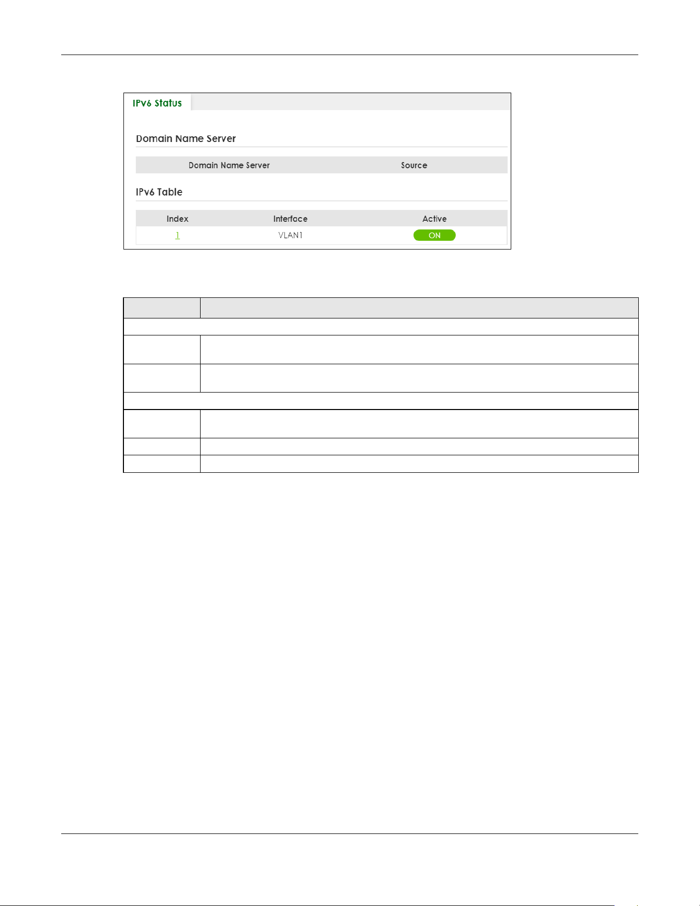
Chapter 24 IPv6
XGS2220 Series User’s Guide
174
Figure 121 SYSTEM > IPv6 > IPv6 Status
The following table describes the labels in this screen.
24.2.1 IPv6 Interface Status Details
Use this screen to view a specific IPv6 interface status and detailed information. Click an interface index
number in the SYSTEM > IPv6 > IPv6 Status screen. The following screen opens.
Table 61 SYSTEM > IPv6 > IPv6 Status
LABEL DESCRIPTION
Domain Name Server
Domain Name
Server
This field displays the IP address of the DNS server.
Source This field displays whether the DNS server address is configured manually (Static) or obtained
automatically using DHCPv6.
IPv6 Table
Index This field displays the index number of an IPv6 interface. Click on an index number to view more
interface details.
Interface This is the name of the IPv6 interface you created.
Active This field displays whether the IPv6 interface is activated or not.

Chapter 24 IPv6
XGS2220 Series User’s Guide
175
Figure 122 SYSTEM > IPv6 > IPv6 Status > IPv6 Interface Details
The following table describes the labels in this screen.
Table 62 SYSTEM > IPv6 > IPv6 Status > IPv6 Interface Details
LABEL DESCRIPTION
Static IPv6 Active
This field displays whether the IPv6 interface is activated or not.
MTU Size This field displays the Maximum Transmission Unit (MTU) size for IPv6 packets on this interface.
ICMPv6
Rate Limit
Bucket Size
This field displays the maximum number of ICMPv6 error messages which are allowed to transmit
in a given time interval. If the bucket is full, subsequent error messages are suppressed.
ICMPv6
Rate Limit
Error
Interval
This field displays the time period (in milliseconds) during which ICMPv6 error messages of up to
the bucket size can be transmitted. 0 means no limit.
ND DAD
Active
This field displays whether Neighbor Discovery (ND) Duplicate Address Detection (DAD) is
enabled on the interface.
Number of
DAD
Attempts
This field displays the number of consecutive neighbor solicitations the Switch sends for this
interface.
NS-Interval
(millisecon
d)
This field displays the time interval (in milliseconds) at which neighbor solicitations are re-sent for
this interface.
ND
Reachable
Time
(millisecon
d)
This field displays how long (in milliseconds) a neighbor is considered reachable for this interface.
Link-Local
Address
This field displays the Switch’s link-local IP address and prefix generated by the interface. It also
shows whether the IP address is preferred, which means it is a valid address and can be used as a
sender or receiver address.

Chapter 24 IPv6
XGS2220 Series User’s Guide
176
24.3 IPv6 Global Setup
Use this screen to configure the global IPv6 settings. Click SYSTEM > IPv6 > IPv6 Global Setup to display
the screen as shown next.
Global
Unicast
Address
This field displays the Switch’s global unicast address to identify this interface.
Joined
Group
Address
This field displays the IPv6 multicast addresses of groups the Switch’s interface joins.
DHCPv6 Client Active
This field displays whether the Switch acts as a DHCPv6 client to get an IPv6 address from a DHCPv6 server.
Identity Association
An Identity Association (IA) is a collection of addresses assigned to a DHCP client, through which the server and
client can manage a set of related IP addresses. Each IA must be associated with exactly one interface.
IA Type The IA type is the type of address in the IA. Each IA holds one type of address. IA_NA means an
identity association for non-temporary addresses and IA_TA is an identity association for
temporary addresses.
IAID Each IA consists of a unique IAID and associated IP information.
T1 This field displays the DHCPv6 T1 timer. After T1, the Switch sends the DHCPv6 server a Renew
message.
An IA_NA option contains the T1 and T2 fields, but an IA_TA option does not. The DHCPv6 server
uses T1 and T2 to control the time at which the client contacts with the server to extend the
lifetimes on any addresses in the IA_NA before the lifetimes expire.
T2 This field displays the DHCPv6 T2 timer. If the time T2 is reached and the server does not respond,
the Switch sends a Rebind message to any available server.
State This field displays the state of the TA. It shows
Active when the Switch obtains addresses from a DHCpv6 server and the TA is created.
Renew when the TA’s address lifetime expires and the Switch sends out a Renew message.
Rebind when the Switch does not receive a response from the original DHCPv6 server and sends
out a Rebind message to another DHCPv6 server.
SID This field displays the DHCPv6 server’s unique ID.
Address This field displays the Switch’s global address which is assigned by the DHCPv6 server.
Preferred
Lifetime
This field displays how long (in seconds) that the global address remains preferred.
Valid
Lifetime
This field displays how long (in seconds) that the global address is valid.
DNS This field displays the DNS server address assigned by the DHCPv6 server.
Domain List This field displays the address record when the Switch queries the DNS server to resolve domain
names.
Restart
DHCPv6 Client
Click Restart to send a new DHCP request to the DHCPv6 server and update the IPv6 address and
DNS information for this interface.
Table 62 SYSTEM > IPv6 > IPv6 Status > IPv6 Interface Details (continued)
LABEL DESCRIPTION
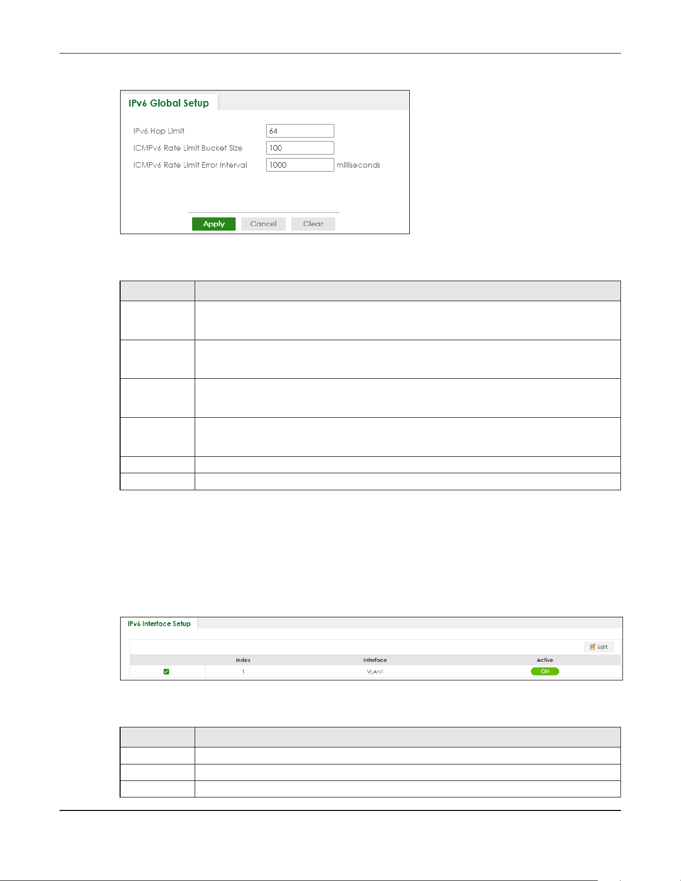
Chapter 24 IPv6
XGS2220 Series User’s Guide
177
Figure 123 SYSTEM > IPv6 > IPv6 Global Setup
The following table describes the labels in this screen.
24.4 IPv6 Interface Setup
Use this screen to view and configure an IPv6 interface you create in the SYSTEM > Interface Setup
screen. Click SYSTEM > IPv6 > IPv6 Interface Setup to display the screen as shown next.
Figure 124 SYSTEM > IPv6 > IPv6 Interface Setup
The following table describes the labels in this screen.
Table 63 SYSTEM > IPv6 > IPv6 Global Setup
LABEL DESCRIPTION
IPv6 Hop Limit Specify the maximum number of hops (from 1 to 255) in router advertisements. This is the
maximum number of hops on which an IPv6 packet is allowed to transmit before it is discarded by
an IPv6 router, which is similar to the TTL field in IPv4.
ICMPv6 Rate
Limit Bucket
Size
Specify the maximum number of ICMPv6 error messages (from 1 to 200) which are allowed to
transmit in a given time interval. If the bucket is full, subsequent error messages are suppressed.
ICMPv6 Rate
Limit Error
Interval
Specify the time period (from 0 to 2147483647 milliseconds) during which ICMPv6 error messages
of up to the bucket size can be transmitted. 0 means no limit.
Apply Click Apply to save your changes to the Switch’s run-time memory. The Switch loses these
changes if it is turned off or loses power, so use the Save link on the top navigation panel to save
your changes to the non-volatile memory when you are done configuring.
Cancel Click Cancel to begin configuring this screen afresh.
Clear Click Clear to reset the fields to the factory defaults.
Table 64 SYSTEM > IPv6 > IPv6 Interface Setup
LABEL DESCRIPTION
Index This is the interface index number.
Interface This is the name of the IPv6 interface you created.
Active This field displays whether the IPv6 interface is activated or not.
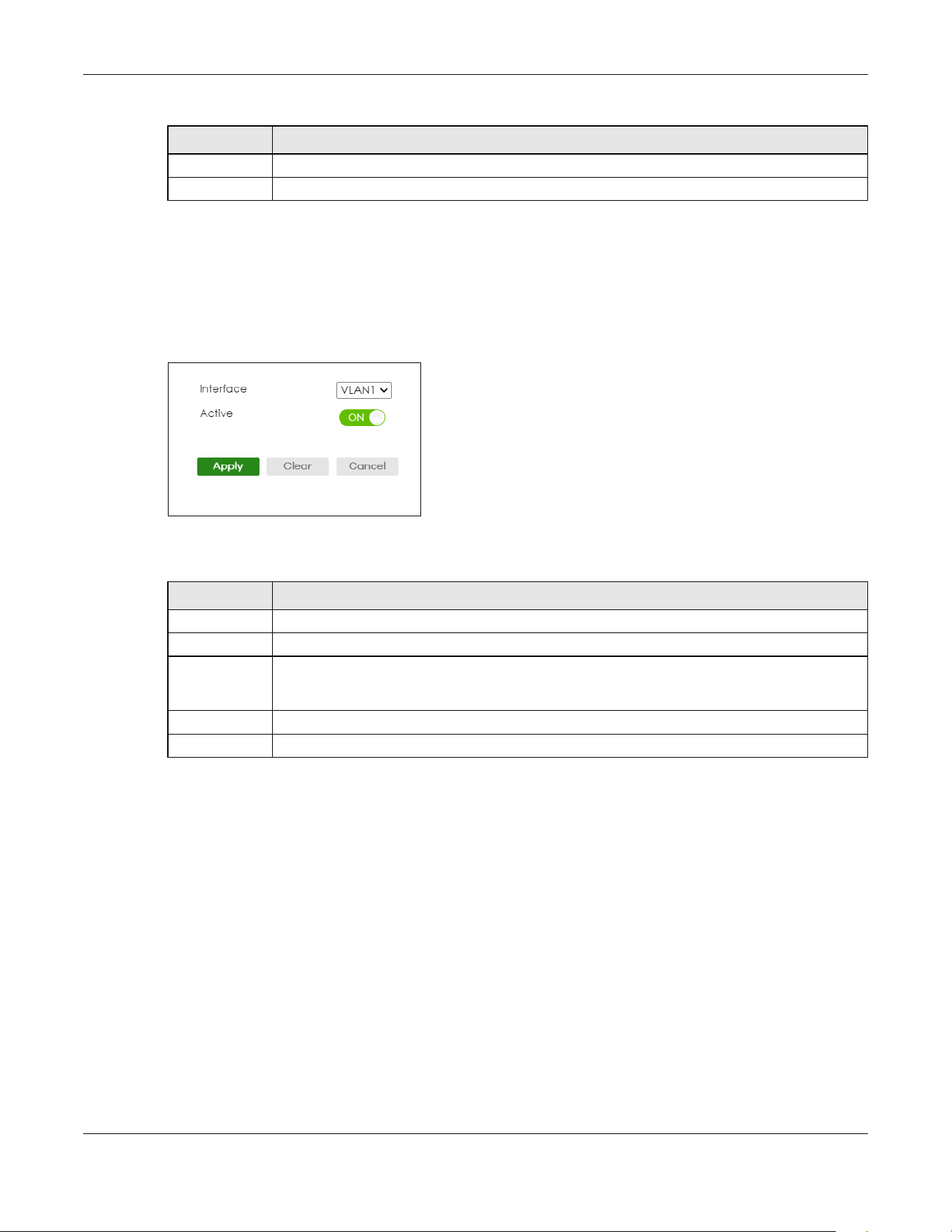
Chapter 24 IPv6
XGS2220 Series User’s Guide
178
24.4.1 Edit an IPv6 Interface
Use this screen to turn on or off an IPv6 interface you create in the SYSTEM > Interface Setup screen.
Select an entry and click Edit in the SYSTEM > IPv6 > IPv6 Interface Setup screen to display the screen as
shown next.
Figure 125 SYSTEM > IPv6 > IPv6 Interface Setup > Edit
The following table describes the labels in this screen.
24.5 IPv6 Link-Local Address Setup
A link-local address uniquely identifies a device on the local network (the LAN). It is similar to a “private IP
address” in IPv4. You can have the same link-local address on multiple interfaces on a device. A link-
local unicast address has a predefined prefix of fe80::/10.
Use this screen to view and configure the interface’s link-local address and default gateway. Click
SYSTEM > IPv6 > IPv6 Addressing > IPv6 Link-Local Address Setup to display the screen as shown next.
Note: You should first create an IPv6 interface in the SYSTEM > Interface Setup screen.
Select an entry’s check box to select a specific entry.
Edit Click Edit to edit the selected interface.
Table 64 SYSTEM > IPv6 > IPv6 Interface Setup (continued)
LABEL DESCRIPTION
Table 65 SYSTEM > IPv6 > IPv6 Interface Setup > Edit
LABEL DESCRIPTION
Interface Select the IPv6 interface you want to configure.
Active Enable the switch button to enable the interface.
Apply Click Apply to save your changes to the Switch’s run-time memory. The Switch loses these
changes if it is turned off or loses power, so use the Save link on the top navigation panel to save
your changes to the non-volatile memory when you are done configuring.
Clear Click Clear to clear the fields to the factory defaults.
Cancel Click Cancel to not save the configuration you make and return to the last screen.
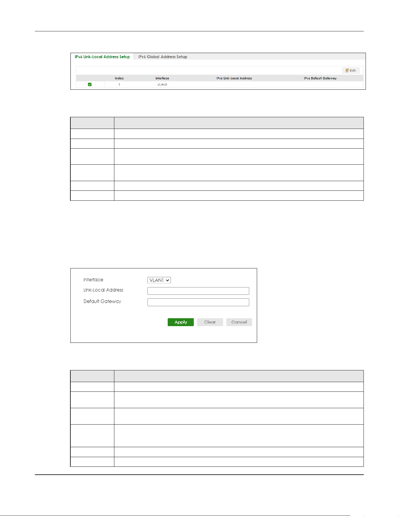
Chapter 24 IPv6
XGS2220 Series User’s Guide
179
Figure 126 SYSTEM > IPv6 > IPv6 Addressing > IPv6 Link-Local Address Setup
The following table describes the labels in this screen.
24.5.1 Edit an IPv6 Link-Local Address
Use this screen to configure the link-local address and default gateway of an IPv6 interface you create
in the SYSTEM > Interface Setup screen. Select an entry and click Edit in the SYSTEM > IPv6 > IPv6
Addressing > IPv6 Link-Local Address Setup screen to display this screen.
Figure 127 SYSTEM > IPv6 > IPv6 Addressing > IPv6 Link-Local Address Setup > Edit
The following table describes the labels in this screen.
Table 66 SYSTEM > IPv6 > IPv6 Addressing > IPv6 Link-Local Address Setup
LABEL DESCRIPTION
Index This is the interface index number.
Interface This is the name of the IPv6 interface you created.
IPv6 Link-Local
Address
This is the static IPv6 link-local address for the interface.
IPv6 Default
Gateway
This is the default gateway IPv6 address for the interface.
Select an entry’s check box to select a specific entry.
Edit Click Edit to edit the selected entry.
Table 67 SYSTEM > IPv6 > IPv6 Addressing > IPv6 Link-Local Address Setup > Edit
LABEL DESCRIPTION
Interface Select the IPv6 interface you want to configure.
Link-Local
Address
Manually configure a static IPv6 link-local address for the interface.
Default
Gateway
Set the default gateway IPv6 address for the interface. When an interface cannot find a routing
information for a frame’s destination, it forwards the packet to the default gateway.
Apply Click Apply to save your changes to the Switch’s run-time memory. The Switch loses these
changes if it is turned off or loses power, so use the Save link on the top navigation panel to save
your changes to the non-volatile memory when you are done configuring.
Clear Click Clear to clear the fields to the factory defaults.
Cancel Click Cancel to not save the configuration you make and return to the last screen.
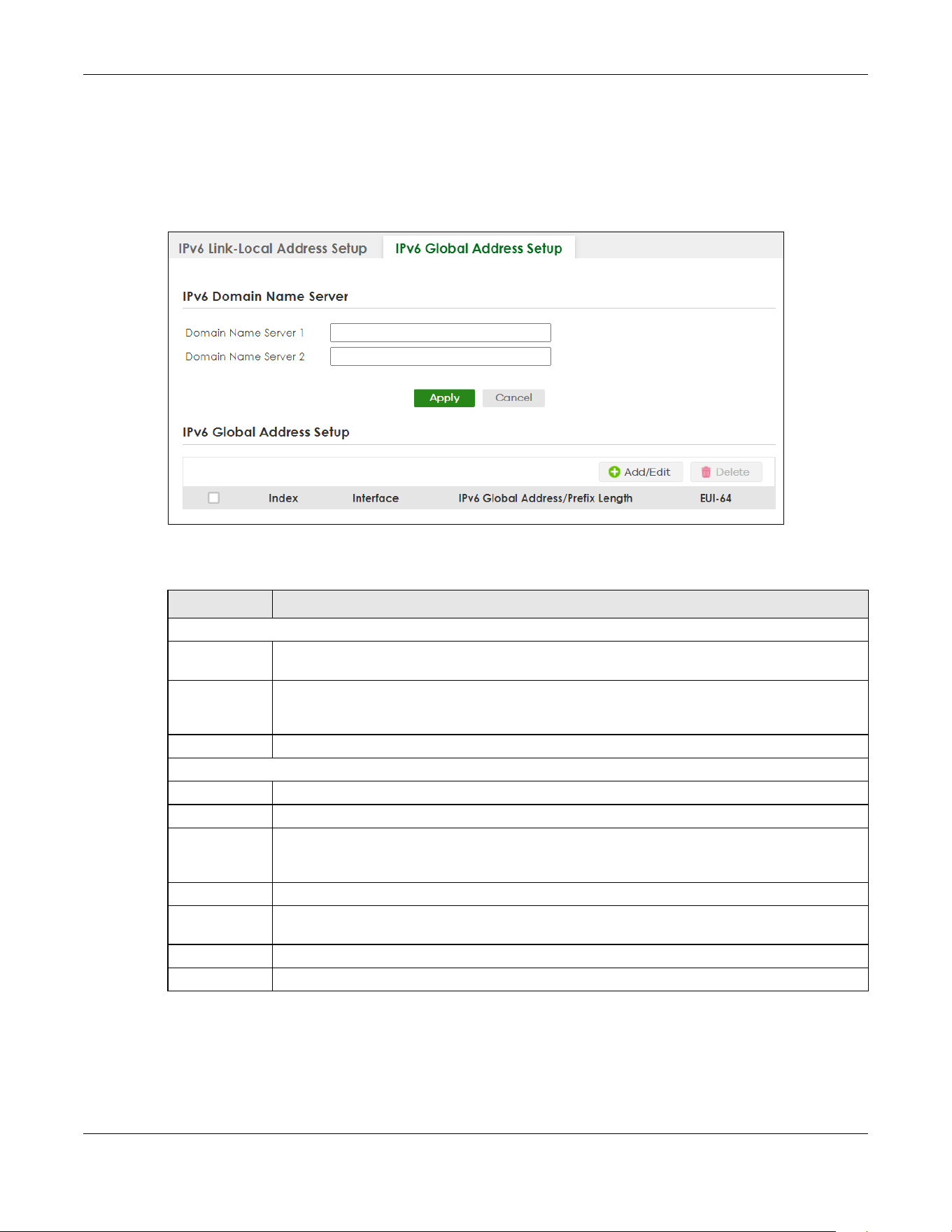
Chapter 24 IPv6
XGS2220 Series User’s Guide
180
24.6 IPv6 Global Address Setup
Use this screen to view and configure the interface’s IPv6 global address. Click SYSTEM > IPv6 Addressing
> IPv6 Global Address Setup to display the screen as shown next.
Figure 128 SYSTEM > IPv6 > IPv6 Addressing > IPv6 Global Address Setup
The following table describes the labels in this screen.
24.6.1 Add/Edit an IPv6 Global Address
Use this screen to configure the interface’s IPv6 global address. Click Add/Edit, or select an entry and
click Add/Edit in the SYSTEM > IPv6 Addressing > IPv6 Global Address Setup screen to display this screen.
Table 68 SYSTEM > IPv6 > IPv6 Addressing > IPv6 Global Address Setup
LABEL DESCRIPTION
IPv6 Domain Name Server
Domain Name
Server 1/2
Enter a domain name server IPv6 address in order to be able to use a domain name instead of an
IP address.
Apply Click Apply to save your changes to the Switch’s run-time memory. The Switch loses these
changes if it is turned off or loses power, so use the Save link on the top navigation panel to save
your changes to the non-volatile memory when you are done configuring.
Cancel Click this to reset the Domain Name Server values in this screen to their last-saved values.
IPv6 Global Address Setup
Index This is the interface index number.
Interface This is the name of the IPv6 interface you created.
IPv6 Global
Address/Prefix
Length
This field displays the IPv6 global address and prefix length for the interface.
EUI-64 This shows whether the interface ID of the global address is generated using the EUI-64 format.
Select an entry’s check box to select a specific entry. Otherwise, select the check box in the
table heading row to select all entries.
Add/Edit Click Add/Edit to add a new entry or edit a selected one.
Delete Click Delete to remove the selected entries.
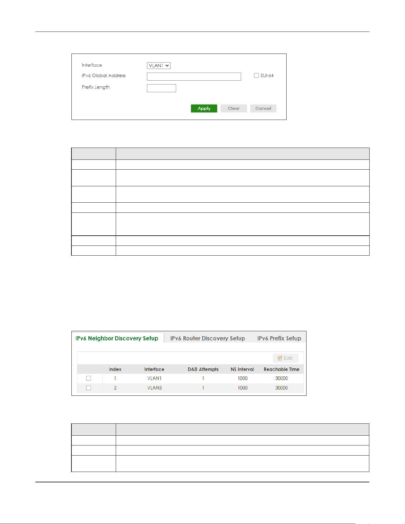
Chapter 24 IPv6
XGS2220 Series User’s Guide
181
Figure 129 SYSTEM > IPv6 > IPv6 Addressing > IPv6 Global Address Setup > Add/Edit
The following table describes the labels in this screen.
24.7 IPv6 Neighbor Discovery Setup
Use this screen to configure neighbor discovery settings for each interface. Click SYSTEM > IPv6 > IPv6
Neighbor Discovery > IPv6 Neighbor Discovery Setup to display the screen as shown next.
Figure 130 SYSTEM > IPv6 > IPv6 Neighbor Discovery > IPv6 Neighbor Discovery Setup
The following table describes the labels in this screen.
Table 69 SYSTEM > IPv6 > IPv6 Addressing > IPv6 Global Address Setup > Add/Edit
LABEL DESCRIPTION
Interface Select the IPv6 interface you want to configure.
IPv6 Global
Address
Manually configure a static IPv6 global address for the interface.
Prefix Length Specify an IPv6 prefix length that specifies how many most significant bits (start from the left) in
the address compose the network address.
EUI-64 Select this option to have the interface ID be generated automatically using the EUI-64 format.
Apply Click Apply to save your changes to the Switch’s run-time memory. The Switch loses these
changes if it is turned off or loses power, so use the Save link on the top navigation panel to save
your changes to the non-volatile memory when you are done configuring.
Clear Click Clear to clear the fields to the factory defaults.
Cancel Click Cancel to not save the configuration you make and return to the last screen.
Table 70 SYSTEM > IPv6 > IPv6 Neighbor Discovery > IPv6 Neighbor Discovery Setup
LABEL DESCRIPTION
Index This is the interface index number.
Interface This is the name of the IPv6 interface you created.
DAD Attempts This field displays the number of consecutive neighbor solicitations the Switch sends for this
interface.

Chapter 24 IPv6
XGS2220 Series User’s Guide
182
24.7.1 Edit an IPv6 Neighbor Discovery
Use this screen to configure neighbor discovery settings for each interface. Select an entry and click Edit
in the SYSTEM > IPv6 > IPv6 Neighbor Discovery > IPv6 Neighbor Discovery Setup screen to display this
screen.
Figure 131 SYSTEM > IPv6 > IPv6 Neighbor Discovery > IPv6 Neighbor Discovery Setup > Edit
The following table describes the labels in this screen.
NS Interval This field displays the time interval (in milliseconds) at which neighbor solicitations are re-sent for
this interface.
Reachable
Time
This field displays how long (in milliseconds) a neighbor is considered reachable for this interface.
Select an entry’s check box to select a specific entry.
Edit Click Edit to edit the selected entry.
Table 70 SYSTEM > IPv6 > IPv6 Neighbor Discovery > IPv6 Neighbor Discovery Setup (continued)
LABEL DESCRIPTION
Table 71 SYSTEM > IPv6 > IPv6 Neighbor Discovery > IPv6 Neighbor Discovery Setup > Edit
LABEL DESCRIPTION
Interface Select the IPv6 interface you want to configure.
DAD Attempts The Switch uses Duplicate Address Detection (DAD) with neighbor solicitation and advertisement
messages to check whether an IPv6 address is already in use before assigning it to an interface.
Specify the number of consecutive neighbor solicitations (from 0 to 600) the Switch sends for this
interface. Enter 0 to turn off DAD.
NS Interval Specify the time interval (from 1000 to 3600000 milliseconds) at which neighbor solicitations are re-
sent for this interface.
Reachable
Time
Specify how long (from 1000 to 3600000 milliseconds) a neighbor is considered reachable for this
interface.
Apply Click Apply to save your changes to the Switch’s run-time memory. The Switch loses these
changes if it is turned off or loses power, so use the Save link on the top navigation panel to save
your changes to the non-volatile memory when you are done configuring.
Clear Click Clear to clear the fields to the factory defaults.
Cancel Click Cancel to not save the configuration you make and return to the last screen.
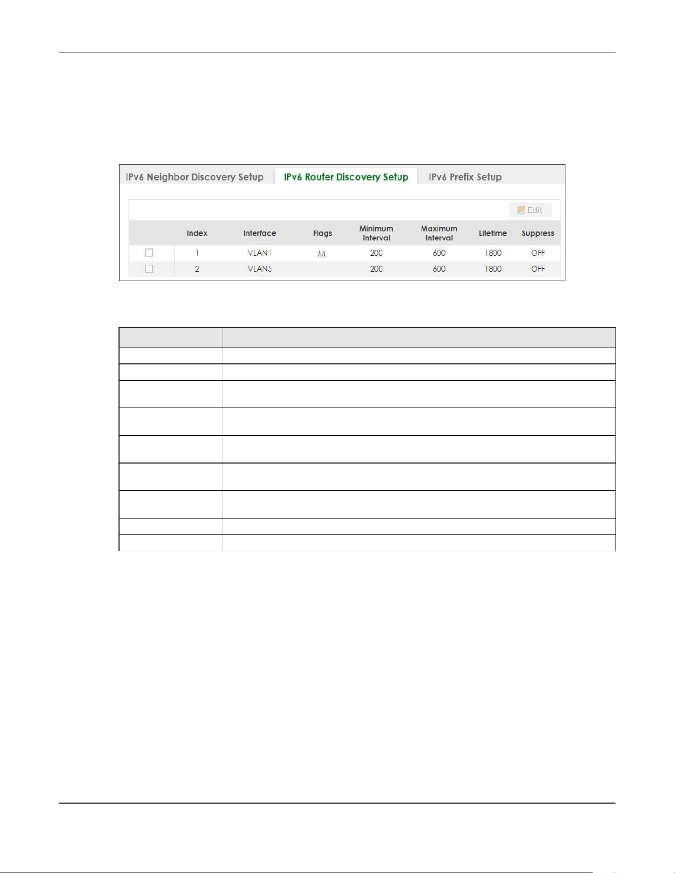
Chapter 24 IPv6
XGS2220 Series User’s Guide
183
24.8 IPv6 Router Discovery Setup
Use this screen to configure router discovery settings for each interface. Click SYSTEM > IPv6 > IPv6
Neighbor Discovery > IPv6 Router Discovery Setup to display the screen as shown next.
Figure 132 SYSTEM > IPv6 > IPv6 Neighbor Discovery > IPv6 Router Discovery Setup
The following table describes the labels in this screen.
24.8.1 Edit IPv6 Router Discovery
Use this screen to configure router discovery settings for each interface. Select an entry and click Edit in
the SYSTEM > IPv6 > IPv6 Neighbor Discovery > IPv6 Router Discovery Setup screen to display the screen
as shown next.
Table 72 SYSTEM > IPv6 > IPv6 Neighbor Discovery > IPv6 Router Discovery Setup
LABEL DESCRIPTION
Index This is the interface index number.
Interface This is the name of the IPv6 interface you created.
Flags This field displays whether IPv6 hosts use DHCPv6 to obtain IPv6 stateful addresses (M) and/
or additional configuration settings (O).
Minimum Interval This field displays the minimum time interval at which the Switch sends router
advertisements for this interface.
Maximum Interval This field displays the maximum time interval at which the Switch sends router
advertisements for this interface.
Lifetime This field displays how long the router in router advertisements can be used as a default
router for this interface.
Suppress This field displays whether the Switch sends router advertisements and responses to router
solicitations on this interface (ON) or not (OFF).
Select an entry’s check box to select a specific entry.
Edit Click Edit to edit the selected entry.

Chapter 24 IPv6
XGS2220 Series User’s Guide
184
Figure 133 SYSTEM > IPv6 > IPv6 Neighbor Discovery > IPv6 Router Discovery Setup > Edit
The following table describes the labels in this screen.
24.9 IPv6 Prefix Setup
Use this screen to configure the Switch’s IPv6 prefix list for each interface. Click SYSTEM > IPv6 > IPv6
Neighbor Discovery > IPv6 Prefix Setup to display the screen as shown next.
Table 73 SYSTEM > IPv6 > IPv6 Neighbor Discovery > IPv6 Router Discovery Setup > Edit
LABEL DESCRIPTION
Interface Select the IPv6 interface you want to configure.
Flags Select the Managed Config Flag option to have the Switch set the “managed address
configuration” flag (the M flag) to 1 in IPv6 router advertisements, which means IPv6 hosts
use DHCPv6 to obtain IPv6 stateful addresses. De-select the option to set the flag to 0 and
the host will not use DHCPv6 to obtain IPv6 stateful addresses.
Select the Other Config Flag option to have the Switch set the “Other stateful
configuration” flag (the O flag) to 1 in IPv6 router advertisements, which means IPv6 hosts
use DHCPv6 to obtain additional configuration settings, such as DNS information. De-select
the option to set the flag to 0 and the host will not use DHCPv6 to obtain additional
configuration settings.
Minimum Interval Specify the minimum time interval (from 3 to 1350 seconds) at which the Switch sends
router advertisements for this interface.
Note: The minimum time interval cannot be greater than three-quarters of the
maximum time interval.
Maximum Interval Specify the maximum time interval (from 4 to 1800 seconds) at which the Switch sends
router advertisements for this interface.
Lifetime Specify how long (from 0 to 9000 seconds) the router in router advertisements can be used
as a default router for this interface.
Suppress Enable the switch button to set the Switch to not send router advertisements and
responses to router solicitations on this interface.
Apply Click Apply to save your changes to the Switch’s run-time memory. The Switch loses these
changes if it is turned off or loses power, so use the Save link on the top navigation panel to
save your changes to the non-volatile memory when you are done configuring.
Clear Click Clear to clear the fields to the factory defaults.
Cancel Click Cancel to not save the configuration you make and return to the last screen.
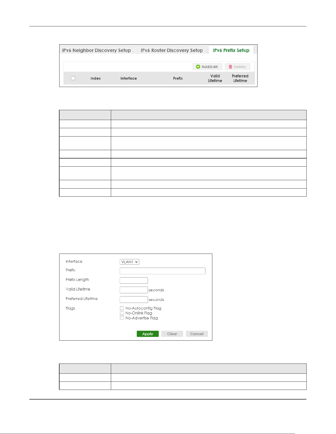
Chapter 24 IPv6
XGS2220 Series User’s Guide
185
Figure 134 SYSTEM > IPv6 > IPv6 Neighbor Discovery > IPv6 Prefix Setup
The following table describes the labels in this screen.
24.9.1 Add/Edit IPv6 Prefix
Use this screen to configure the Switch’s IPv6 prefix list for each interface. Click Add/Edit, or select an
entry and click Add/Edit in the SYSTEM > IPv6 > IPv6 Neighbor Discovery > IPv6 Prefix Setup screen to
display this screen.
Figure 135 SYSTEM > IPv6 > IPv6 Neighbor Discovery > IPv6 Prefix Setup > Add/Edit
The following table describes the labels in this screen.
Table 74 SYSTEM > IPv6 > IPv6 Neighbor Discovery > IPv6 Prefix Setup
LABEL DESCRIPTION
Index This is the interface index number.
Interface This is the name of the IPv6 interface you created.
Prefix This field displays the IPv6 prefix and prefix length that the Switch includes in router
advertisements for this interface.
Valid Lifetime This field displays the IPv6 prefix valid lifetime.
Preferred Lifetime This field displays the preferred lifetime of an IPv6 address generated from the prefix.
Select an entry’s check box to select a specific entry. Otherwise, select the check box in
the table heading row to select all entries.
Add/Edit Click Add/Edit to add a new entry or edit a selected one.
Delete Click Delete to remove the selected entries.
Table 75 SYSTEM > IPv6 > IPv6 Neighbor Discovery > IPv6 Prefix Setup > Add/Edit
LABEL DESCRIPTION
Interface Select the IPv6 interface you want to configure.
Prefix Set the IPv6 prefix that the Switch includes in router advertisements for this interface.
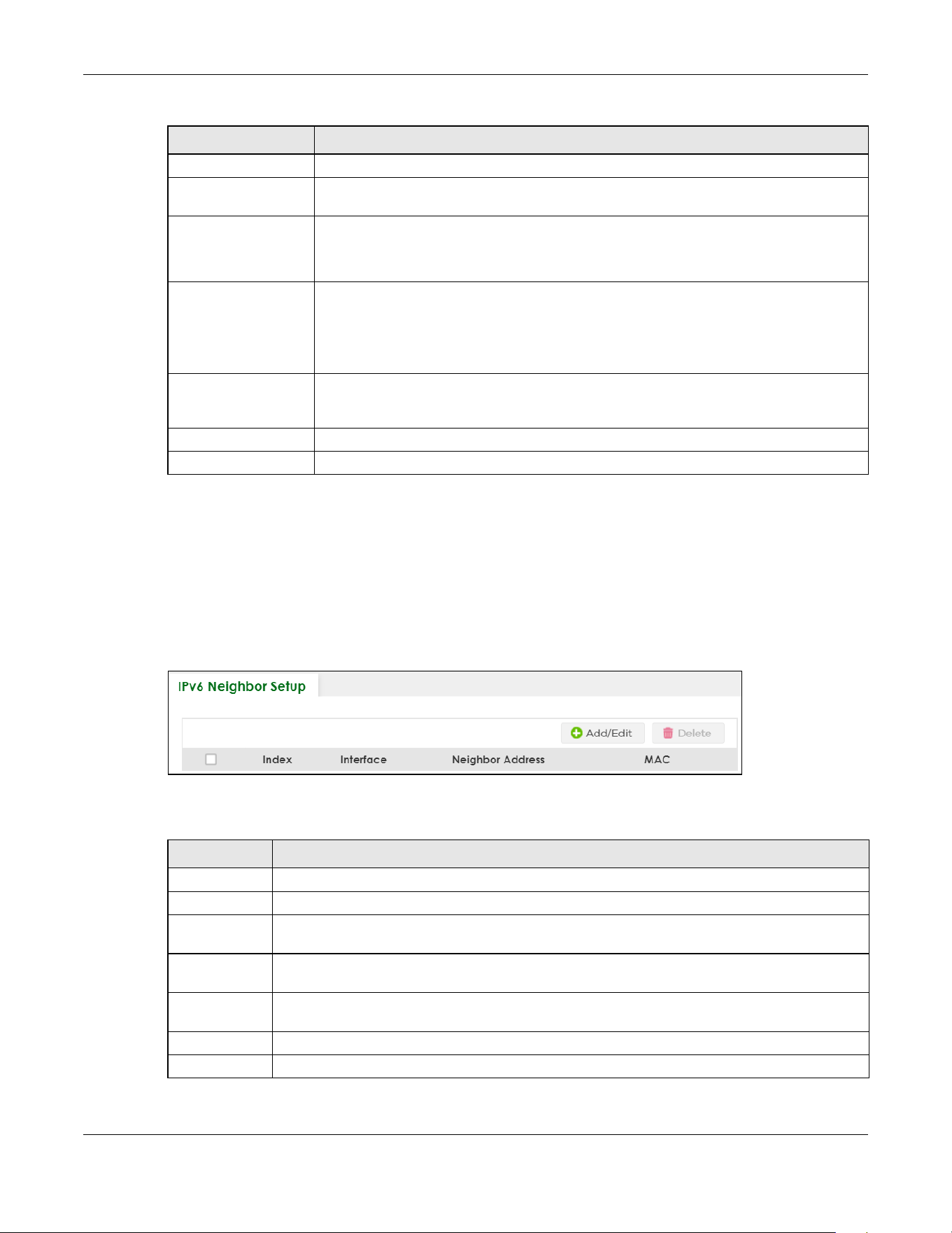
Chapter 24 IPv6
XGS2220 Series User’s Guide
186
24.10 IPv6 Neighbor Setup
Use this screen to view and configure static IPv6 neighbor entries in the Switch’s IPv6 neighbor table to
store the neighbor information permanently. Click SYSTEM > IPv6 > IPv6 Neighbor Setup to display the
screen as shown next.
Figure 136 SYSTEM > IPv6 > IPv6 Neighbor Setup
The following table describes the labels in this screen.
Prefix Length Set the prefix length that the Switch includes in router advertisements for this interface.
Valid Lifetime Specify how long (from 0 to 4294967295 seconds) the prefix is valid for on-link
determination.
Preferred Lifetime Specify how long (from 0 to 4294967295 seconds) that addresses generated from the prefix
remain preferred.
The preferred lifetime cannot exceed the valid lifetime.
Flags Select No-Autoconfig Flag to not allow IPv6 hosts to use this prefix.
Select No-Onlink Flag to not allow the specified prefix to be used for on-link determination.
Select No-Advertise Flag to set the Switch to not include the specified IPv6 prefix, prefix
length in router advertisements for this interface.
Apply Click Apply to save your changes to the Switch’s run-time memory. The Switch loses these
changes if it is turned off or loses power, so use the Save link on the top navigation panel to
save your changes to the non-volatile memory when you are done configuring.
Clear Click Clear to clear the fields to the factory defaults.
Cancel Click Cancel to not save the configuration you make and return to the last screen.
Table 75 SYSTEM > IPv6 > IPv6 Neighbor Discovery > IPv6 Prefix Setup > Add/Edit (continued)
LABEL DESCRIPTION
Table 76 SYSTEM > IPv6 > IPv6 Neighbor Setup
LABEL DESCRIPTION
Index This is the interface index number.
Interface This is the name of the IPv6 interface you created.
Neighbor
Address
This field displays the IPv6 address of the neighboring device which can be reached through the
interface.
MAC This field displays the MAC address of the neighboring device which can be reached through the
interface.
Select an entry’s check box to select a specific entry. Otherwise, select the check box in the table
heading row to select all entries.
Add/Edit Click Add/Edit to add a new entry or edit a selected one.
Delete Click Delete to remove the selected entries.

Chapter 24 IPv6
XGS2220 Series User’s Guide
187
24.10.1 Add/Edit IPv6 Neighbor
Use this screen to create a static IPv6 neighbor entry. Click Add/Edit, or select an entry and click Add/
Edit in the SYSTEM > IPv6 > IPv6 Neighbor Setup screen to display this screen.
Figure 137 SYSTEM > IPv6 > IPv6 Neighbor Setup > Add/Edit
The following table describes the labels in this screen.
24.11 DHCPv6 Client Setup
Use this screen to configure the Switch’s DHCP settings when it is acting as a DHCPv6 client. Click SYSTEM
> IPv6 > DHCPv6 Client Setup to display the screen as shown next.
Table 77 SYSTEM > IPv6 > IPv6 Neighbor Setup > Add/Edit
LABEL DESCRIPTION
Interface Select the type of IPv6 interface for which you want to configure. The Switch supports the VLAN
interface type for IPv6 at the time of writing.
Interface ID Specify a unique identification number (from 1 to 4094) for the interface.
A static IPv6 neighbor entry displays in the MONITOR > IPv6 Neighbor Table screen only when the
interface ID is also created in the SYSTEM > Interface Setup screen.
To have IPv6 function properly, you should configure a static VLAN with the same ID number in the
SWITCHING > VLAN screens.
Neighbor
Address
Specify the IPv6 address of the neighboring device which can be reached through the interface.
MAC Specify the MAC address of the neighboring device which can be reached through the
interface.
Apply Click Apply to save your changes to the Switch’s run-time memory. The Switch loses these
changes if it is turned off or loses power, so use the Save link on the top navigation panel to save
your changes to the non-volatile memory when you are done configuring.
Clear Click Clear to clear the fields to the factory defaults.
Cancel Click Cancel to not save the configuration you make and return to the last screen.
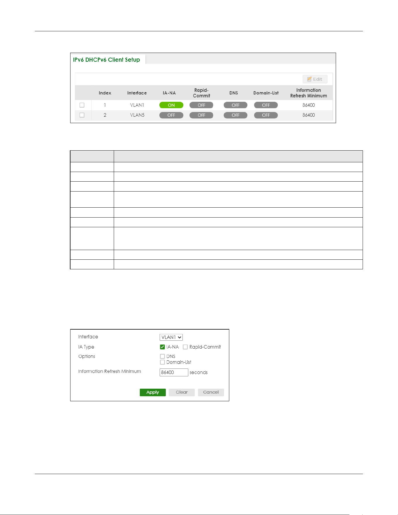
Chapter 24 IPv6
XGS2220 Series User’s Guide
188
Figure 138 SYSTEM > IPv6 > DHCPv6 Client Setup
The following table describes the labels in this screen.
24.11.1 Edit DHCPv6 Client
Use this screen to configure the Switch’s DHCP settings when it is acting as a DHCPv6 client. Select an
entry and click Edit in the SYSTEM > IPv6 > DHCPv6 Client Setup screen to display this screen.
Figure 139 SYSTEM > IPv6 > DHCPv6 Client Setup > Edit
Table 78 SYSTEM > IPv6 > DHCPv6 Client Setup
LABEL DESCRIPTION
Index This is the interface index number.
Interface This is the name of the IPv6 interface you created.
IA-NA This field displays whether the Switch obtains a non-temporary IP address from the DHCPv6 server.
Rapid-Commit This field displays whether the Switch obtains information from the DHCPv6 server by a rapid two-
message exchange.
DNS This field displays whether the Switch obtains DNS server IPv6 addresses from the DHCPv6 server.
Domain-List This field displays whether the Switch obtains a list of domain names from the DHCP server.
Information
Refresh
Minimum
This field displays the time interval (in seconds) at which the Switch exchanges other configuration
information with a DHCPv6 server again.
Select an entry’s check box to select a specific entry.
Edit Click Edit to edit the selected entry.

Chapter 24 IPv6
XGS2220 Series User’s Guide
189
The following table describes the labels in this screen.
Table 79 SYSTEM > IPv6 > DHCPv6 Client Setup > Edit
LABEL DESCRIPTION
Interface Select the IPv6 interface you want to configure.
IA Type Select IA-NA to set the Switch to get a non-temporary IP address from the DHCPv6 server for this
interface.
Optionally, you can also select Rapid-Commit to have the Switch send its DHCPv6 Solicit message
with a Rapid Commit option to obtain information from the DHCPv6 server by a rapid two-
message exchange. The Switch discards any Reply messages that do not include a Rapid
Commit option. The DHCPv6 server should also support the Rapid Commit option to have it work
well.
Options Select DNS to have the Switch obtain DNS server IPv6 addresses and/or select Domain-List to
have the Switch obtain a list of domain names from the DHCP server.
Information
Refresh
Minimum
Specify the time interval (from 600 to 4294967295 seconds) at which the Switch exchanges other
configuration information with a DHCPv6 server again.
Apply Click Apply to save your changes to the Switch’s run-time memory. The Switch loses these
changes if it is turned off or loses power, so use the Save link on the top navigation panel to save
your changes to the non-volatile memory when you are done configuring.
Clear Click Clear to clear the fields to the factory defaults.
Cancel Click Cancel to not save the configuration you make and return to the last screen.

Chapter 25 Logins
XGS2220 Series User’s Guide
190
CHAPTER 25
Logins
25.1 Set Up Login Accounts
Up to five people (one administrator and four non-administrators) may access the Switch through Web
Configurator at any one time.
• An administrator is someone who can both view and configure Switch changes. The user name for
the Administrator is always admin. The default administrator password is 1234.
Note: It is highly recommended that you change the default administrator password (1234).
• A non-administrator (user name is something other than admin) is someone who can view and/or
configure Switch settings. The configuration right varies depending on the user’s privilege level.
Click SYSTEM> Logins to view the screen as shown.
Figure 140 SYSTEM > Logins
Note: The input string in any field of this screen should not contain [ ? ], [ | ], [ ' ], [ " ] or [ , ].
In the Password fields, [ space ] is also not allowed.
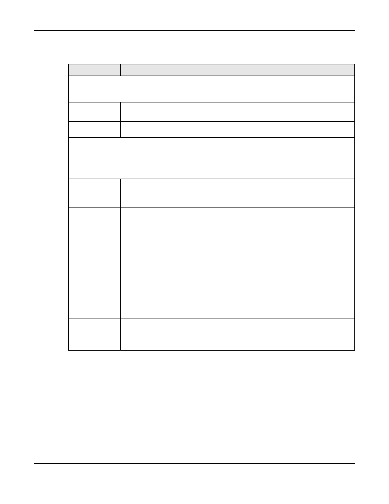
Chapter 25 Logins
XGS2220 Series User’s Guide
191
The following table describes the labels in this screen.
Table 80 SYSTEM > Logins
LABEL DESCRIPTION
Administrator
This is the default administrator account with the “admin” user name. You cannot change the default administrator
user name.
Old Password Type the existing system password (1234 is the default password when shipped).
New Password Enter your new system password. You can enter up to 32 printable ASCII characters.
Retype to
confirm
Retype your new system password for confirmation. You can enter up to 32 printable ASCII
characters.
Edit Logins
You may configure passwords for up to four users. These users can have read-only or read/write access.
Note: You can give users higher privileges through the Web Configurator or the CLI. For more
information on assigning privileges through the CLI see the Ethernet Switch CLI Reference Guide.
Login This is the index of an user account.
User Name Set a user name (up to 32 printable ASCII characters except [ ? ], [ | ], [ ' ], [ " ], or [ , ]).
Password Enter your new system password.
Retype to
confirm
Retype your new system password for confirmation.
Privilege Type the privilege level for this user. At the time of writing, users may have a privilege level of 0,
3, 13, or 14 representing different configuration rights as shown below.
• 0 – Display basic system information.
• 3 – Display configuration or status.
• 13 – Configure features except for login accounts, SNMP user accounts, the
authentication method sequence and authorization settings, multiple logins, administrator
and enable passwords, and configuration information display.
• 14 – Configure login accounts, SNMP user accounts, the authentication method
sequence and authorization settings, multiple logins, and administrator and enable
passwords, and display configuration information.
Users can run command lines if the session’s privilege level is greater than or equal to the
command’s privilege level. The session privilege initially comes from the privilege of the login
account. For example, if the user has a privilege of 5, he or she can run commands that
requires privilege level of 5 or less but not more.
Apply Click Apply to save your changes to the Switch’s run-time memory. The Switch loses these
changes if it is turned off or loses power, so use the Save link on the top navigation panel to
save your changes to the non-volatile memory when you are done configuring.
Cancel Click Cancel to begin configuring this screen afresh.

Chapter 26 SNMP
XGS2220 Series User’s Guide
192
CHAPTER 26
SNMP
26.1 SNMP Overview
This chapter introduces the SNMP screens and shows you how to setup SNMP settings for management.
26.1.1 What You Can Do
• Use the SNMP screen (Section 26.2 on page 192) to configure general SNMP settings.
• Use the SNMP User screen (Section 26.3 on page 194) to create SNMP users for authentication with
managers using SNMP v3 and associate them to SNMP groups.
• Use the SNMP Trap Group screen (Section 26.4 on page 196) to specify the types of SNMP traps that
should be sent to each SNMP manager.
• Use the SNMP Trap Port screen (Section 26.5 on page 197) to enable/disable sending SNMP traps on a
port.
26.2 Configure SNMP
Use this screen to configure your SNMP settings.
Click SYSTEM > SNMP to view the screen as shown.

Chapter 26 SNMP
XGS2220 Series User’s Guide
193
Figure 141 SYSTEM > SNMP
Note: The string of any field in this screen should not contain [ ? ], [ | ], [ ' ], [ " ] or [ , ].
The following table describes the labels in this screen.
Table 81 SYSTEM > SNMP
LABEL DESCRIPTION
General Setting
Use this section to specify the SNMP version and community (password) values.
Version Select the SNMP version for the Switch. The SNMP version on the Switch must match the
version on the SNMP manager. Choose SNMP version 2c (v2c), SNMP version 3 (v3) or both
(v3v2c).
SNMP version 2c is backwards compatible with SNMP version 1.
Get Community Enter the Get Community string, which is the password for the incoming Get- and GetNext-
requests from the management station.
The Get Community string is only used by SNMP managers using SNMP version 2c or lower.
Set Community Enter the Set Community string, which is the password for incoming Set- requests from the
management station.
The Set Community string is only used by SNMP managers using SNMP version 2c or lower.
Trap Community Enter the Trap Community string, which is the password sent with each trap to the SNMP
manager.
The Trap Community string is only used by SNMP managers using SNMP version 2c or lower.
Trap Destination
Use this section to configure where to send SNMP traps from the Switch.
Index This is the index of a trap destination.
Version Specify the version of the SNMP trap messages.
IP Enter the IP addresses of up to four managers to send your SNMP traps to.

Chapter 26 SNMP
XGS2220 Series User’s Guide
194
26.3 Configure SNMP User
Use this screen to create SNMP users for authentication with managers using SNMP v3 and associate
them to SNMP groups. An SNMP user is an SNMP manager. Click SYSTEM > SNMP > SNMP User to view the
screen as shown.
Figure 142 SYSTEM > SNMP > SNMP User
The following table describes the labels in this screen.
26.3.1 Add/Edit SNMP User
Use this screen to create SNMP users for authentication with managers using SNMP v3 and associate
them to SNMP groups. An SNMP user is an SNMP manager. Click Add/Edit, or select an entry and click
Add/Edit in the SYSTEM > SNMP > SNMP User screen to view the screen.
Port Enter the port number upon which the manager listens for SNMP traps.
Username Enter the user name to be sent to the SNMP manager along with the SNMP v3 trap.
This user name must match an existing account on the Switch (configured in the SYSTEM >
SNMP > SNMP User screen).
Apply Click Apply to save your changes to the Switch’s run-time memory. The Switch loses these
changes if it is turned off or loses power, so use the Save link on the top navigation panel to
save your changes to the non-volatile memory when you are done configuring.
Cancel Click Cancel to begin configuring this screen afresh.
Table 81 SYSTEM > SNMP (continued)
LABEL DESCRIPTION
Table 82 SYSTEM > SNMP > SNMP User
LABEL DESCRIPTION
Index This is a read-only number identifying a login account on the Switch.
Username This field displays the user name of a login account on the Switch.
Security Level This field displays whether you want to implement authentication and/or encryption for SNMP
communication with this user.
Authentication This field displays the authentication algorithm used for SNMP communication with this user.
Privacy This field displays the encryption method used for SNMP communication with this user.
Group This field displays the SNMP group to which this user belongs.
Select an entry’s check box to select a specific entry. Otherwise, select the check box in the
table heading row to select all entries.
Add/Edit Click Add/Edit to add a new entry or edit a selected one.
Delete Click Delete to remove the selected entries.

Chapter 26 SNMP
XGS2220 Series User’s Guide
195
Note: Use the user name and password of the login accounts you specify in this screen to
create accounts on the SNMP v3 manager.
Figure 143 SYSTEM > SNMP > SNMP User > Add/Edit
The following table describes the labels in this screen.
Table 83 SYSTEM > SNMP > SNMP User > Add/Edit
LABEL DESCRIPTION
Username Specify the user name (up to 32 printable ASCII characters) of a login account on the Switch.
The string should not contain [ ? ], [ | ], [ ' ], [ " ] or [ , ].
Security Level Select whether you want to implement authentication and/or encryption for SNMP
communication from this user. Choose:
• no auth – to use the user name as the password string to send to the SNMP manager. This is
equivalent to the Get, Set and Trap Community in SNMP v2c. This is the lowest security
level.
• auth – to implement an authentication algorithm for SNMP messages sent by this user.
• priv – to implement authentication and encryption for SNMP messages sent by this user.
This is the highest security level.
Note: The settings on the SNMP manager must be set at the same security level or
higher than the security level settings on the Switch.
Authentication Select an authentication algorithm. MD5 (Message Digest 5) and SHA (Secure Hash Algorithm)
are hash algorithms used to authenticate SNMP data. SHA authentication is generally
considered stronger than MD5, but is slower.
Password Enter the password of up to 32 printable ASCII characters (except [ ? ], [ | ], [ ' ], [ " ], [ space ],
or [ , ]) for SNMP user authentication.
Privacy Specify the encryption method for SNMP communication from this user. You can choose one
of the following:
• DES – Data Encryption Standard is a widely used (but breakable) method of data
encryption. It applies a 56-bit key to each 64-bit block of data.
• AES – Advanced Encryption Standard is another method for data encryption that also
uses a secret key. AES applies a 128-bit key to 128-bit blocks of data.
Password Enter the password of up to 32 printable ASCII characters (except [ ? ], [ | ], [ ' ], [ " ], [ space ],
or [ , ]) for encrypting SNMP packets.
Group SNMP v3 adopts the concept of View-based Access Control Model (VACM) group. SNMP
managers in one group are assigned common access rights to MIBs. Specify in which SNMP
group this user is.
admin – Members of this group can perform all types of system configuration, including the
management of administrator accounts.
read-write – Members of this group have read and write rights, meaning that the user can
create and edit the MIBs on the Switch, except the user account and AAA configuration.
read-only – Members of this group have read rights only, meaning the user can collect
information from the Switch.

Chapter 26 SNMP
XGS2220 Series User’s Guide
196
26.4 SNMP Trap Group
Use this screen to specify the types of SNMP traps that should be sent to each SNMP manager. Click
SYSTEM > SNMP > SNMP Trap Group to view the screen as shown.
Figure 144 SYSTEM > SNMP > SNMP Trap Group
The following table describes the labels in this screen.
Apply Click Apply to save your changes to the Switch’s run-time memory. The Switch loses these
changes if it is turned off or loses power, so use the Save link on the top navigation panel to
save your changes to the non-volatile memory when you are done configuring.
Clear Click Clear to clear the fields to the factory defaults.
Cancel Click Cancel to not save the configuration you make and return to the last screen.
Table 83 SYSTEM > SNMP > SNMP User > Add/Edit (continued)
LABEL DESCRIPTION
Table 84 SYSTEM > SNMP > SNMP Trap Group
LABEL DESCRIPTION
Trap Destination IP Select one of your configured trap destination IP addresses. These are the IP addresses of the
SNMP managers. You must first configure a trap destination IP address in the SYSTEM > SNMP >
SNMP screen.
Use the rest of the screen to select which traps the Switch sends to that SNMP manager.
Select the individual SNMP traps that the Switch is to send to the SNMP station.
The traps are grouped by category. Selecting a category in the heading row automatically
selects all of the SNMP traps under that category. Clear the check boxes for individual traps
that you do not want the Switch to send to the SNMP station. Clearing a category’s check
box automatically clears all of the category’s trap check boxes (the Switch only sends traps
from selected categories).
Apply Click Apply to save your changes to the Switch’s run-time memory. The Switch loses these
changes if it is turned off or loses power, so use the Save link on the top navigation panel to
save your changes to the non-volatile memory when you are done configuring.
Cancel Click Cancel to begin configuring this screen afresh.

Chapter 26 SNMP
XGS2220 Series User’s Guide
197
26.5 Enable or Disable Sending of SNMP Traps on a Port
Click SYSTEM > SNMP > SNMP Trap Port to view the screen as shown. Use this screen to set whether a trap
received on the ports would be sent to the SNMP manager.
Figure 145 SYSTEM > SNMP > SNMP Trap Port (Standalone Mode)
Figure 146 SYSTEM > SNMP > SNMP Trap Port (Stacking Mode)

Chapter 26 SNMP
XGS2220 Series User’s Guide
198
The following table describes the labels in this screen.
26.6 Technical Reference
This section provides technical background information on the topics discussed in this chapter.
26.6.1 About SNMP
Simple Network Management Protocol (SNMP) is an application layer protocol used to manage and
monitor TCP/IP-based devices. SNMP is used to exchange management information between the
network management system (NMS) and a network element (NE). A manager station can manage and
monitor the Switch through the network through SNMP version 1 (SNMPv1), SNMP version 2c or SNMP
version 3. The next figure illustrates an SNMP management operation. SNMP is only available if TCP/IP is
configured.
Table 85 SYSTEM > SNMP > SNMP Trap Port
LABEL DESCRIPTION
Options Select the trap type you want to configure here.
SLOT This field appears only in Stacking mode. Click the drop-down list to choose the slot number of
the Switch in a stack.
Port This field displays the port number. In Stacking mode, the first number represents the slot ID
and the second is the port number. Please note that the default stacking ports (the last four
ports of your Switch) cannot be configured. They are reserved for stacking only.
* Settings in this row apply to all ports.
Use this row only if you want to make some of the settings the same for all ports. Use this row
first to set the common settings and then make adjustments on a port-by-port basis.
Changes in this row are copied to all the ports as soon as you make them.
1/* Settings in this row apply to all ports for the Switch represented by the slot ID (in Stacking
mode).
Use this row only if you want to make some of the settings the same for all ports. Use this row
first to set the common settings and then make adjustments on a port-by-port basis.
Note: Changes in this row are copied to all the ports as soon as you make them.
Active Select this check box to enable the trap type of SNMP traps on this port. The Switch sends the
related traps received on this port to the SNMP manager.
Clear this check box to disable the sending of SNMP traps on this port.
Apply Click Apply to save your changes to the Switch’s run-time memory. The Switch loses these
changes if it is turned off or loses power, so use the Save link on the top navigation panel to
save your changes to the non-volatile memory when you are done configuring.
Cancel Click Cancel to begin configuring this screen afresh.

Chapter 26 SNMP
XGS2220 Series User’s Guide
199
Figure 147 SNMP Management Model
An SNMP managed network consists of two main components: agents and a manager.
An agent is a management software module that resides in a managed Switch (the Switch). An agent
translates the local management information from the managed Switch into a form compatible with
SNMP. The manager is the console through which network administrators perform network management
functions. It executes applications that control and monitor managed devices.
The managed devices contain object variables or managed objects that define each piece of
information to be collected about a Switch. Examples of variables include number of packets received,
node port status, and so on. A Management Information Base (MIB) is a collection of managed objects.
SNMP allows a manager and agents to communicate for the purpose of accessing these objects.
SNMP itself is a simple request or response protocol based on the manager or agent model. The
manager issues a request and the agent returns responses using the following protocol operations:
SNMP v3 and Security
SNMP v3 enhances security for SNMP management. SNMP managers can be required to authenticate
with agents before conducting SNMP management sessions.
Security can be further enhanced by encrypting the SNMP messages sent from the managers.
Encryption protects the contents of the SNMP messages. When the contents of the SNMP messages are
encrypted, only the intended recipients can read them.
Supported MIBs
A MIB is a collection of managed objects that is organized according to hierarchy. The objects define
the attributes of the managed device, which includes the names, status, access rights, and data types.
Each object can be addressed through an object identifier (OID).
Table 86 SNMP Commands
LABEL DESCRIPTION
Get Allows the manager to retrieve an object variable from the agent.
GetNext Allows the manager to retrieve the next object variable from a table or list within an agent. In
SNMPv1, when a manager wants to retrieve all elements of a table from an agent, it initiates a
Get operation, followed by a series of GetNext operations.
Set Allows the manager to set values for object variables within an agent.
Trap Used by the agent to inform the manager of some events.

Chapter 26 SNMP
XGS2220 Series User’s Guide
200
MIBs let administrators collect statistics and monitor status and performance. The Switch uses standard
public (RFC-defined) MIBs for standard functionality, and private MIBs that support additional Switch
functionality. Private MIBs contain Switch specific managed objects.
To view a list of standard MIBs supported by your Switch, see the product datasheet at www.zyxel.com
(Support > Download Library > Datasheet).
To get the private MIBs supported by your Switch, download (and unzip) the correct model MIB from
www.zyxel.com (Support > Download Library > MIB File).
SNMP Traps
The Switch sends traps to an SNMP manager when an event occurs. The following tables outline the
SNMP traps by category.
Table 87 SNMP System Traps
OPTION OBJECT LABEL OBJECT ID DESCRIPTION
coldstart coldStart 1.3.6.1.6.3.1.1.5.1 This trap is sent when the Switch is turned on.
warmstart warmStart 1.3.6.1.6.3.1.1.5.2 This trap is sent when the Switch restarts.
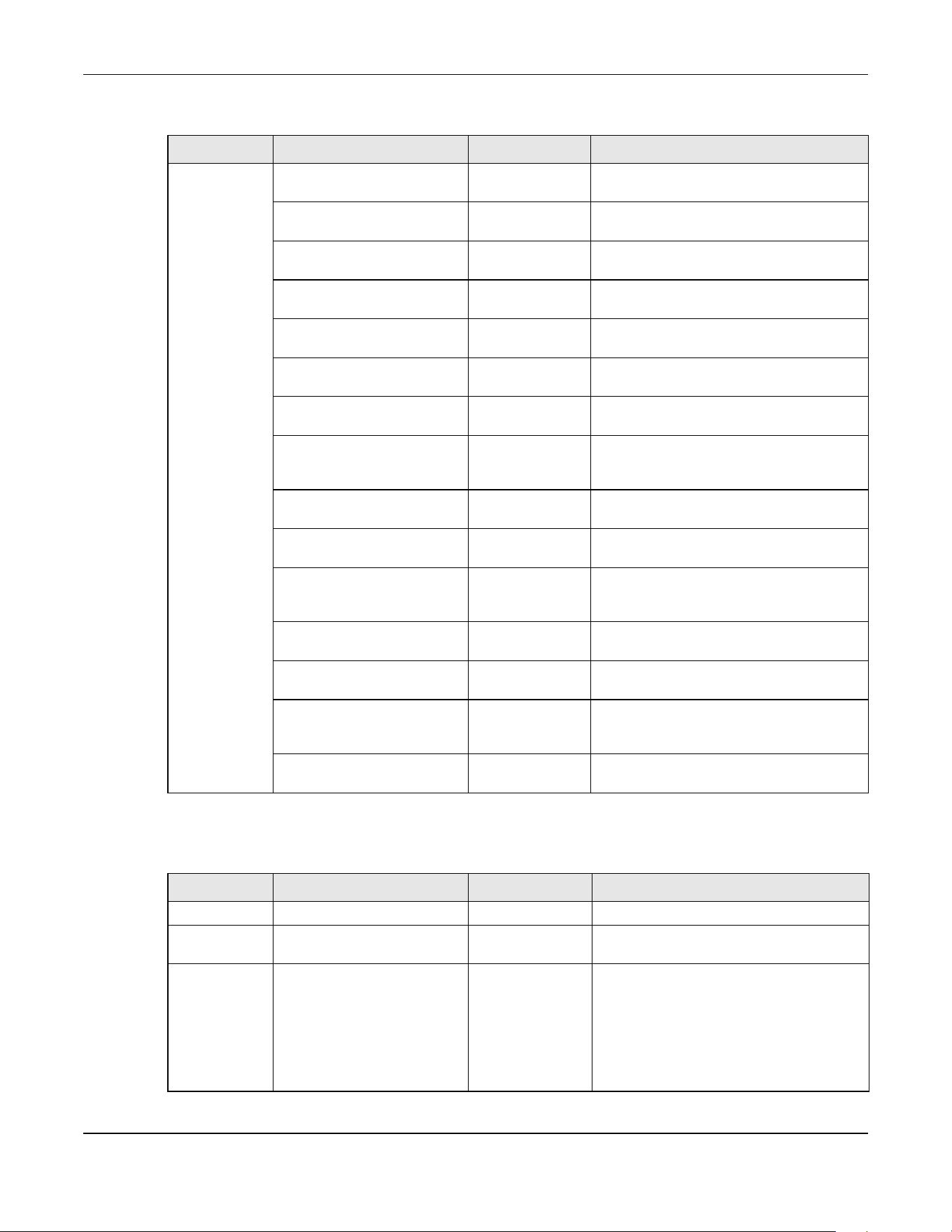
Chapter 26 SNMP
XGS2220 Series User’s Guide
201
stacking zyStackingChannelUp 1.3.6.1.4.1.890.1.15
.3.97.4.1
This trap is sent when stacking channel
changes from down to up.
zyStackingChannelDown 1.3.6.1.4.1.890.1.15
.3.97.4.2
This trap is sent when stacking channel
changes from up to down.
zyStackingSlotAttach 1.3.6.1.4.1.890.1.15
.3.97.4.3
This trap is sent when a Switch is attached
successfully into the stacking system.
zyStackingSlotDetach 1.3.6.1.4.1.890.1.15
.3.97.4.4
This trap is sent when a Switch is detached
from a stacking system.
zyStackingNewMaster 1.3.6.1.4.1.890.1.15
.3.97.4.5
This trap is sent when a Switch is selected as
the new master in stacking system.
zyStackingUpgradeFirmwareF
ail
1.3.6.1.4.1.890.1.15
.3.97.4.6
This trap is sent when upgrade firmware fails
on a stacked Switch.
zyStackingNewBackup 1.3.6.1.4.1.890.1.15
.3.97.4.7
This trap is sent when a Switch is selected as
the new backup in stacking system.
zyStackingBackupTakeover 1.3.6.1.4.1.890.1.15
.3.97.4.8
This trap is sent when a master Switch is loss
and replaced by a backup to become the
new master.
zyStackingNewMasterFromTak
eover
1.3.6.1.4.1.890.1.15
.3.97.4.9
This trap is sent when a new master Switch
takes over from a former master.
zyStackingSyncConfFail 1.3.6.1.4.1.890.1.15
.3.97.4.10
This trap is sent when a configuration sync
fails.
zyStackingSysRestoreConfFail 1.3.6.1.4.1.890.1.15
.3.97.4.11
This trap is sent when a backup Switch
becomes the master and configuration
restore fails.
zyStackingSlotInitFail 1.3.6.1.4.1.890.1.15
.3.97.4.12
This trap is sent when a newly attached
Switch initialization fails.
zyStackingSlotChangeIndex 1.3.6.1.4.1.890.1.15
.3.97.4.13
This trap is sent when a stacking slot index
changes.
zyStackingPriorityChange 1.3.6.1.4.1.890.1.15
.3.97.4.14
This trap is sent when the stacking priority
changes. Stacking priority determines which
is master.
zyStackingTopologyChange 1.3.6.1.4.1.890.1.15
.3.97.4.15
This trap is sent when a stacking topology
(ring or chain) changes.
Table 88 SNMP Interface Traps
OPTION OBJECT LABEL OBJECT ID DESCRIPTION
linkup linkUp 1.3.6.1.6.3.1.1.5.4 This trap is sent when the Ethernet link is up.
linkdown linkDown 1.3.6.1.6.3.1.1.5.3 This trap is sent when the Ethernet link is
down.
lldp lldpRemTablesChange 1.0.8802.1.1.2.0.0.1 The trap is sent when entries in the remote
database have any updates.
Link Layer Discovery Protocol (LLDP), defined
as IEEE 802.1ab, enables LAN devices that
support LLDP to exchange their configured
settings. This helps eliminate configuration
mismatch issues.
Table 87 SNMP System Traps (continued)
OPTION OBJECT LABEL OBJECT ID DESCRIPTION
Chapter 26 SNMP
XGS2220 Series User’s Guide
202
Table 90 SNMP IP Traps
OPTION OBJECT LABEL OBJECT ID DESCRIPTION
ping pingProbeFailed 1.3.6.1.2.1.80.0.1 This trap is sent when a single ping probe
fails.
pingTestFailed 1.3.6.1.2.1.80.0.2 This trap is sent when a ping test (consisting
of a series of ping probes) fails.
pingTestCompleted 1.3.6.1.2.1.80.0.3 This trap is sent when a ping test is
completed.
traceroute traceRouteTestFailed 1.3.6.1.2.1.81.0.2 This trap is sent when a traceroute test fails.
traceRouteTestCompleted 1.3.6.1.2.1.81.0.3 This trap is sent when a traceroute test is
completed.
Table 91 SNMP Switch Traps
OPTION OBJECT LABEL OBJECT ID DESCRIPTION
rmon RmonRisingAlarm 1.3.6.1.2.1.16.0.1 This trap is sent when a variable goes over
the RMON "rising" threshold.
RmonFallingAlarm 1.3.6.1.2.1.16.0.2 This trap is sent when the variable falls below
the RMON "falling" threshold.

Chapter 27 Stacking
XGS2220 Series User’s Guide
203
CHAPTER 27
Stacking
27.1 Stacking Overview
This chapter introduces switch stacking and discusses how to configure stacking mode on the Switch to
form a switch system.
27.1.1 What You Can Do
• Use the Stacking Status screen (Section 27.2 on page 204) to view the stacking system status and
topology for the Switch.
• Use the Stacking Setup screen (Section 27.3 on page 207) to configure the stacking system.
• Use the Stacking Port Setup screen (Section 27.4 on page 209) to select the media type, SFP+
transceiver or Direct Attach Copper (DAC) that is attached to the 10 Gigabit interface.
27.1.2 What you need to know
Stacking is directly connecting Switches to form a larger system that behaves as a single Switch or a
virtual chassis with increased port density.
Figure 148 Switch Stacking Concept
The last four combo ports of your Switch are dedicated for Switch stacking. At the time of writing, the
Switch can only connect to another Switch of the same model and firmware version.
Note: Up to four Switches per stack are allowed.
You can manage each Switch in the stack from a master Switch using its Web Configurator or console.
Each Switch supports up to two stacking channels. Use the master Switch to assign a ‘slot ID’ for each
‘linecard’ non-master Switch. ‘Slot’ refers to a Switch in the ‘virtual chassis’ stack.
Table 92 Stacking Channels and Ports
STACKING CHANNEL STACKING PORTS
XGS2220-30 / XGS2220-30HP / XGS2220-30F 1 27, 28
229, 30
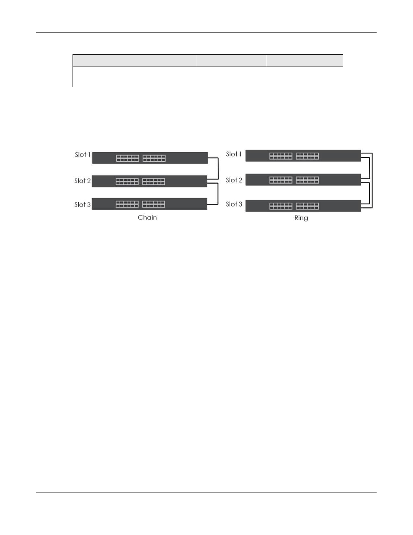
Chapter 27 Stacking
XGS2220 Series User’s Guide
204
In stacking mode, the stacking channel is using link-aggregation. The default algorithm type is src-dst-
mac, and is not configurable.
You can build a Switch stack using a ring or chain topology. In a ring topology, the last Switch is
connected to the first.
Figure 149 Stacking Topology
Use the master Switch to assign a ‘slot ID’ for each ‘linecard’ non-master Switch. ‘Slot’ refers to a Switch
in the ‘virtual chassis’ stack.
The advantages of stacking are:
• High port density – for example, two 24-port Switches can become one 48-port logical Switch
• Centralized management – log into a single IP address of the master switch to control all Switches in
the stacking system using the Web Configurator, CLI, SNMP or FTP
• Redundancy – Data redundancy allows traffic to be forwarded even if one Switch in the stack fails.
Management redundancy lets you still manage the stack even if one Switch in the stack fails
• Modularity and hot-swappable – you can add, remove, or replace Switches to increase or decrease
the stack with minimum disruption to ongoing network traffic.
27.2 Stacking Status
Click SYSTEM > Stacking > Stacking Status to display the screen as shown next.
XGS2220-54 / XGS2220-54HP / XGS2220-54FP 1 51, 52
253, 54
Table 92 Stacking Channels and Ports (continued)
STACKING CHANNEL STACKING PORTS

Chapter 27 Stacking
XGS2220 Series User’s Guide
205
Figure 150 SYSTEM > Stacking > Stacking Status
The following table describes the labels in this screen.
27.2.1 Stacking Slot Details
Click a slot number in SYSTEM > Stacking > Stacking Status to display the Stacking Status Details screen
as shown next.
Table 93 SYSTEM > Stacking > Stacking Status
LABEL DESCRIPTION
Slot ‘Slot’ refers to a Switch in the ‘virtual chassis’ stack. This field displays the slot ID of the stacked
Switch. You can click the ID number to go to the Stacking Status Details screen.
Name This field displays the model name of the stacked Switch
.
Status This field displays whether the stacked Switch is active or inactive in a stack system.
Init means the slot ID is being initialized by the master Switch.
active* means the Switch is in the stack, but some items failed to initiate. See the system logs for
details. If the Switch is not a master, disconnect and reconnect the stacking port and wait.
Restart the Switch if it still displays active*. If the Switch is a master, restart it or choose another
master.
MAC address This field displays the MAC address of the stacked Switch
.
Role This field displays whether the Switch is a master, backup or linecard. There’s only one master
and one backup Switch in the stacking mode; all others are linecard Switches.
Stacking Up
Time
This field displays the time that the active Switch has been running in a stack.
The master Switch records the time when a Switch in Stacking mode joins the stacking system.
Time count will restart when master Switch changes.
Stacking Topology: Ring/Chain
Slot
No. This field displays the slot ID number of the stacked Switch.
Stacking Channel1
Neighbor This field displays the neighbor Switch that is connected using slot channel 1 of the Switch.
Speed This field displays the Ethernet speed of stacking channel 1 of the Switch.
Stacking Channel2
Neighbor This field displays the neighbor Switch that is connected to slot channel 2 of the Switch.
Speed This field displays the Ethernet speed of stacking channel 2 of the Switch.

Chapter 27 Stacking
XGS2220 Series User’s Guide
206
Figure 151 SYSTEM > Stacking > Stacking Status > Stacking Status Details
The following table describes the labels in this screen.
Table 94 SYSTEM > Stacking > Stacking Status > Stacking Status Details
LABEL DESCRIPTION
Slot This field displays the slot ID of the Switch.
Stacking This field displays whether the Switch is active in the stacking system.
Role This field displays whether the stacked Switch is a master, backup or linecard Switch
.
Force Master
Mode
This field displays whether the Force Master Mode is enabled or disabled on this Switch. The
Force Master Mode forces this Switch to become a master Switch. This Switch will have the
highest priority over all other Switch in the stack. If two Switches are set as masters, they will have
the same priority level, but the Switch that has the longest active run-time will be selected as the
master Switch automatically.
Priority This field displays the priority level of the Switch. A higher number represents higher priority.
Slot ID After
Reboot
This field displays the slot ID of the Switch after a reboot. You can save the slot ID of the Switch
after a reboot by clicking Freeze in the SYSTEM > Stacking > Stacking Setup screen.
Stacking Status This field displays whether the stacked Switch is active or inactive in a stack system.
Init means the slot ID is being initialized by the master Switch.
active* means the Switch is in the stack, but some items failed to initiate. See the system logs for
details. If the Switch is not a master, disconnect and reconnect the stacking port and wait.
Restart the Switch if it still displays active*. If the Switch is a master, restart it or choose another
master.
Master Capable This field displays whether the Switch has capacity to become a master Switch. Auto means the
stack system master election process will determine if the Switch can be assigned as a master
Switch.
Stacking MAC
Address
This field displays the stacking Switch MAC address.
Stacking
Channel 1
This field displays the status of the port stacking channel 1 of the Switch. It will display up for
active or down for inactive.
Stacking
Channel 2
This field displays the status of the port stacking channel 2 of the Switch. It will display up for
active or down for inactive.
System Up Time This field displays how long the Switch has been running since it last restarted or was turned on.

Chapter 27 Stacking
XGS2220 Series User’s Guide
207
27.3 Stacking Setup
A supported Switch can change between stacking and standalone mode by enabling the Active
switch (ON/OFF) in the SYSTEM > Stacking > Stacking Setup screen.
Note: When you change modes, all configurations (except user accounts), including Running
Config, Config1, Config2 and Custom Default configuration, will be erased. Only user
accounts will be kept after mode changing if saved to a configuration file. The Switch
will reboot with the Stacking/Standalone factory default settings on the current
configuration file. You should back up current configurations if you want to reload
them. Note that a configuration file of a mode (Standalone or Stacking) can only be
applied under the same mode.
Note: When the Switch changes from Standalone mode to Stacking mode, it will use the
static IP address 192.168.1.1 by default; when the Switch changes from Stacking mode
back to Standalone mode, it will use a DHCP-assigned IP address obtained from the
DHCP server. (if the Switch cannot obtain an IP address from the DHCP server, it will use
the default IP 192.168.1.1 until it can get a DHCP-assigned IP)
Stacking will automatically choose a master Switch in a stack but you can overwrite that by actively
forcing a Switch to become a master Switch. In the SYSTEM > Stacking > Stacking Setup screen, click the
switch on to enable Force Master Mode to choose the master Switch. This master Switch will have the
highest priority over all other stacked Switches even when they have the same priority value.
If two or more Switches have Force Master Mode enabled, they have the same System Priority. Then the
Switch with the longest up-time is selected. Uptime is measured in increments of 10 minutes. The Switch
with the higher number of increments is selected. If they have the same uptime, then the Switch with the
lowest MAC address will be the master.
This is the master election priority in a stack system:
1 Active Force Master Mode
2 Highest System Priority
3 Longest System Up Time
4 Lowest MAC Address
Note: Master election occurs when a stacking port link status changes (up or down). The link
Stacking Up
Time
This field displays the time that the active Switch has been running in a stack.
The master Switch records the time when a Switch in Stacking mode joins the stacking system.
Time count will restart when master Switch changes.
ZyNOS Version
*Running / Flash
This field displays the ZyNOS firmware that is currently running on the Switch.
Table 94 SYSTEM > Stacking > Stacking Status > Stacking Status Details (continued)
LABEL DESCRIPTION

Chapter 27 Stacking
XGS2220 Series User’s Guide
208
status changes when (for example):
– a stacking port cable is disconnected
– a Switch in the stack reboots (as happens after you change stacking mode to
standalone)
– you add a Switch to the stack or
– a Switch in the stack shuts down.
Use the following procedure to create a stack:
1 Select a Switch to be the master. Change its mode to Stacking mode. You will see a message asking
you to confirm the change. Click YES to confirm. The Switch will reboot automatically using the current
configuration file (with factory default settings) and the default IP interface settings in Stacking mode.
2 After reboot completes, the master LED will turn on.
3 Configure the Switch stacking priority to a high value, such as 63.
4 Change a second Switch to stacking mode and wait for it to finish rebooting automatically. This master
LED will also turn on.
5 Connect the two Switches using the stacking ports for the Switch defined.
6 The second Switch master LED will then turn off, and its Sys LED will blink while it is initializing. Please wait
until it stops blinking, indicating that it has joined the stack.
7 Repeat steps 4 to 6 to connect other Switches to the stack.
When the Switch is in Stacking mode, the Web Configurator will change port and VLAN port settings to
support the stacking mode.
Click SYSTEM > Stacking > Stacking Setup to see the following screen.
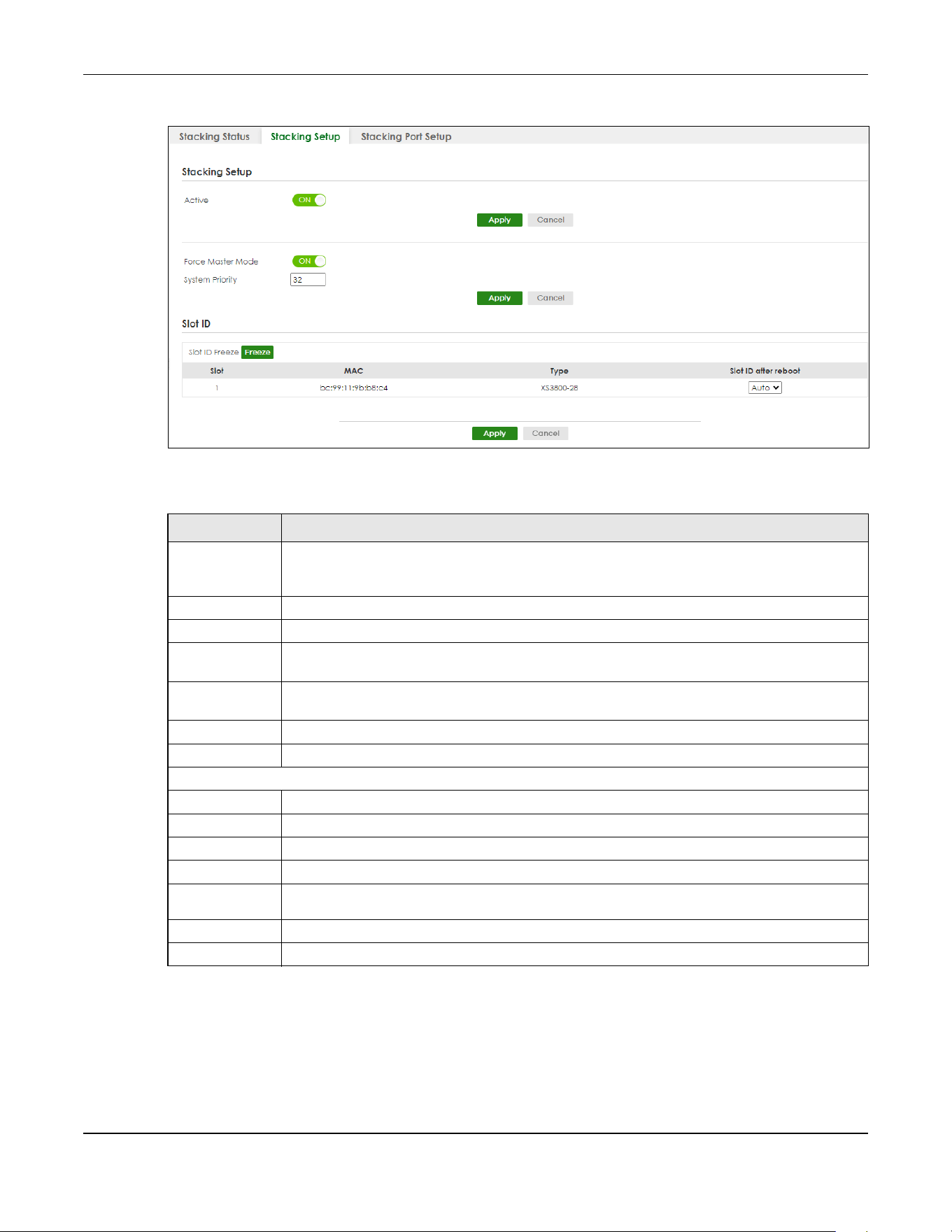
Chapter 27 Stacking
XGS2220 Series User’s Guide
209
Figure 152 SYSTEM > Stacking > Stacking Setup
The following table describes the labels in this screen.
27.4 Stacking Port Setup
Click SYSTEM > Stacking > Stacking Port Setup to display the screen as shown next.
Table 95 SYSTEM > Stacking > Stacking Setup
LABEL DESCRIPTION
Active Enable the ON/OFF switch to put the Switch in Stacking mode. This will erase the Running
Configuration, Config1 and Config2. The master Switch’s login will remain unchanged. If you
want to reload a previous configuration, please back one up first.
Apply Click Apply to activate Stacking mode/go back to Standalone mode.
Cancel Click Cancel to note save your changes.
Force Master
Mode
Enable the ON/OFF switch to force this Switch to become a master Switch.
System Priority Enter a number (from1 to 63) to assign a priority for the stacking Switch. The higher the number,
the higher the priority.
Apply Click Apply to save changes made to the Force Master Mode and System Priority fields.
Cancel Click Cancel to clear the Active Force Master Mode and System Priority fields.
Slot ID
Slot ID Freeze Click the Freeze button to have the Switch retain its slot ID after reboot.
Slot This field displays the slot or port channel of the stacked Switch.
MAC This field displays the MAC address of the stacked Switch.
Type This field displays the model name of the Switch.
Slot ID after
reboot
Choose Auto to have a new slot ID assigned after reboot. If you want to keep the original
slot ID after reboot, you can click Freeze or select an ID in the Slot ID after reboot list box.
Apply Click Apply to save the Slot ID after reboot field.
Cancel Click Cancel to clear the Slot ID after reboot field.
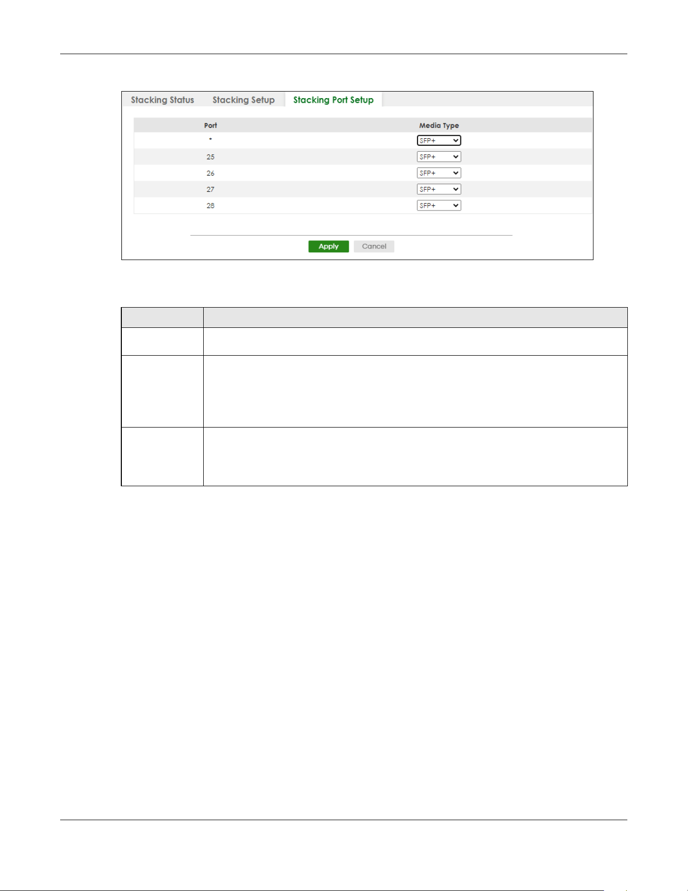
Chapter 27 Stacking
XGS2220 Series User’s Guide
210
Figure 153 SYSTEM > Stacking > Stacking Port Setup
The following table describes the labels in this screen.
Table 96 SYSTEM > Stacking > Stacking Port Setup
LABEL DESCRIPTION
Port This is the port index number. These are the default stacking ports (the last four ports of your
Switch). They are reserved for stacking only.
* Settings in this row apply to all ports.
Use this row only if you want to make some settings the same for all ports. Use this row first to set
the comment settings and then make adjustments on a port-by-port basis.
Note: Changes in this row are copied to all the ports as soon as you make them.
Media Type You can insert either an SFP+ transceiver or an SFP+ Direct Attach Copper (DAC) cable into the
10 Gigabit interface of the Switch.
Select the media type (SFP+ or DAC10G) of the SFP+ module that is attached to the 10 Gigabit
interface.

Chapter 28 Switch Setup
XGS2220 Series User’s Guide
211
CHAPTER 28
Switch Setup
28.1 Switch Setup Overview
Use this screen to do the Switch’s basic setup configuration, for example, VLAN (Virtual Local Area
Network) type, enabling switching protocols, and MAC learning aging time setup.
28.1.1 Introduction to VLANs
A VLAN (Virtual Local Area Network) allows a physical network to be partitioned into multiple logical
networks. Devices on a logical network belong to one group. A device can belong to more than one
group. With VLAN, a device cannot directly talk to or hear from devices that are not in the same groups;
the traffic must first go through a router.
In MTU (Multi-Tenant Unit) applications, VLAN is vital in providing isolation and security among the
subscribers. When properly configured, VLAN prevents one subscriber from accessing the network
resources of another on the same LAN, thus a user will NOT see the printers and hard disks of another
user in the same building.
VLAN also increases network performance by limiting broadcasts to a smaller and more manageable
logical broadcast domain. In traditional switched environments, all broadcast packets go to each and
every individual port. With VLAN, all broadcasts are confined to a specific broadcast domain.
Note: VLAN is unidirectional; it only governs outgoing traffic.
28.2 Switch Setup
Click SYSTEM > Switch Setup in the navigation panel to display the screen as shown. The VLAN setup
screens change depending on whether you choose 802.1Q or Port Based in the VLAN Type field in this
screen.
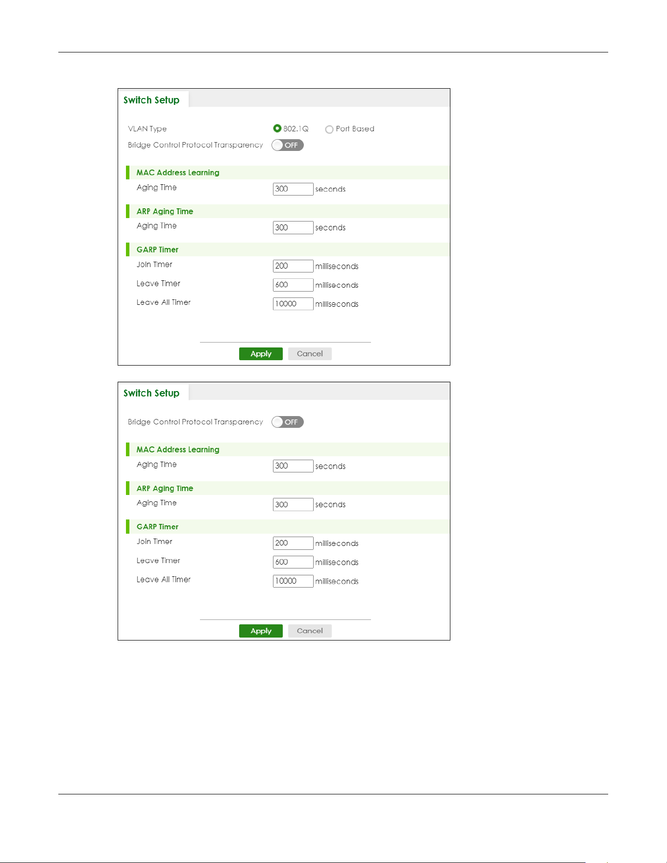
Chapter 28 Switch Setup
XGS2220 Series User’s Guide
212
Figure 154 SYSTEM > Switch Setup (Standalone Mode)
Figure 155 Basic Setting > Switch Setup (Stacking Mode)
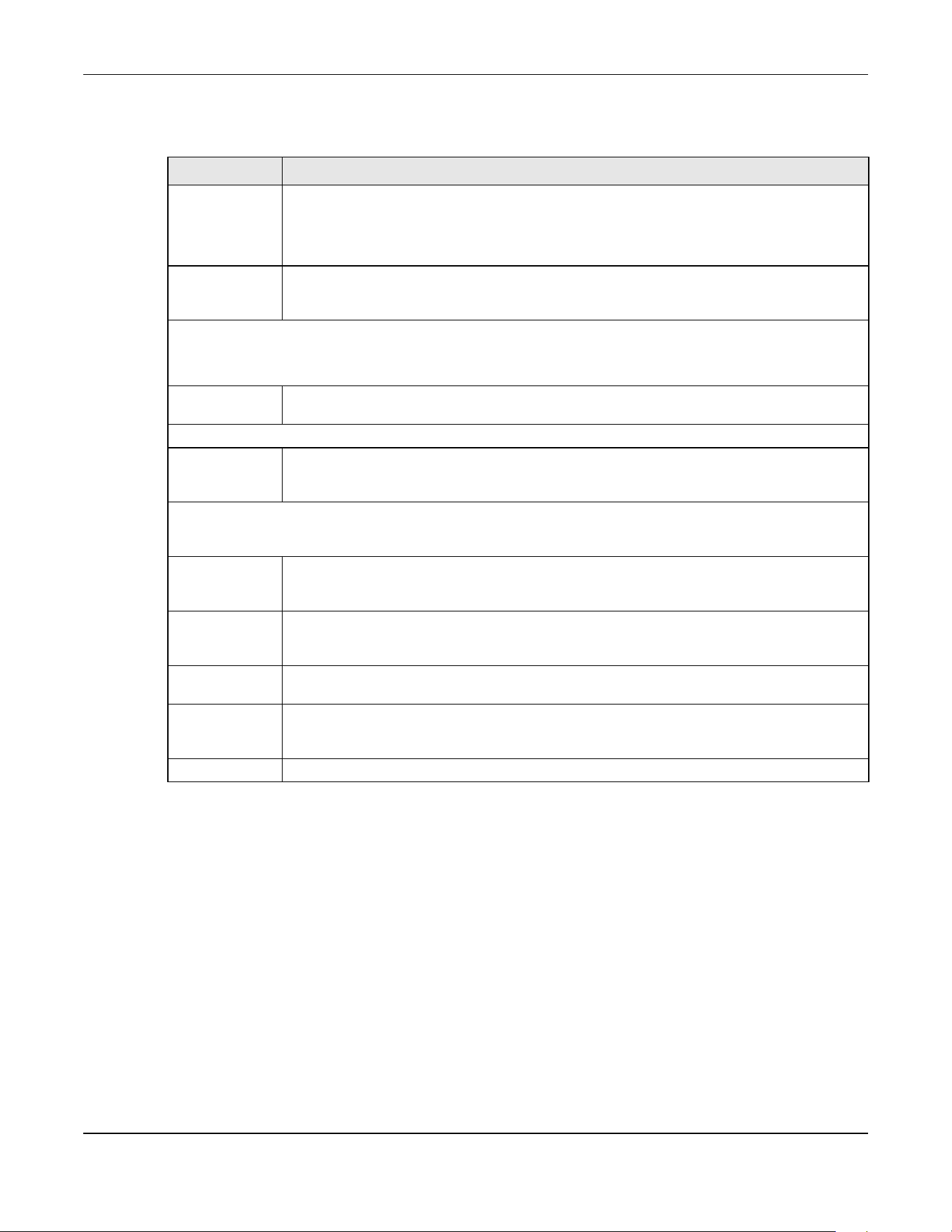
Chapter 28 Switch Setup
XGS2220 Series User’s Guide
213
The following table describes the labels in this screen.
Table 97 SYSTEM > Switch Setup
LABEL DESCRIPTION
VLAN Type
(Standalone
mode only)
Choose 802.1Q or Port Based. The SWITCHING > VLAN link and its sub-links only appears in the
navigation panel when you choose 802.1Q VLAN type in this screen.
The Switch does not have port-based VLAN available in stacking mode (Active is enabled in
SYSTEM > Stacking > Stacking Setup), so this field does not display in stacking mode.
Bridge Control
Protocol
Transparency
Enable the ON/OFF switch to allow the Switch to handle bridging control protocols (STP, for
example). You also need to define how to treat a BPDU in the PORT > Port Setup screen.
MAC Address Learning
MAC address learning reduces outgoing traffic broadcasts. For MAC address learning to occur on a port, the port
must be active.
Aging Time Enter a time from 10 to 1000000 seconds. This is how long all dynamically learned MAC
addresses remain in the MAC address table before they age out (and must be relearned).
ARP Aging Time
Aging Time Enter a time from 60 to 1000000 seconds. This is how long dynamically learned ARP entries
remain in the ARP table before they age out (and must be relearned). The setting here applies
to ARP entries which are newly added in the ARP table after you click Apply.
GARP Timer: Switches join VLANs by making a declaration. A declaration is made by issuing a Join message using
GARP. Declarations are withdrawn by issuing a Leave message. A Leave All message terminates all registrations.
GARP timers set declaration timeout values. See the chapter on VLAN setup for more background information.
Join Timer Join Timer sets the duration of the Join Period timer for GVRP in milliseconds. Each port has a Join
Period timer. The allowed Join Time range is between 100 and 65535 milliseconds; the default is
200 milliseconds. See the chapter on VLAN setup for more background information.
Leave Timer Leave Timer sets the duration of the Leave Period timer for GVRP in milliseconds. Each port has a
single Leave Period timer. Leave Time must be two times larger than Join Timer; the default is 600
milliseconds.
Leave All
Timer
Leave All Timer sets the duration of the Leave All Period timer for GVRP in milliseconds. Each port
has a single Leave All Period timer. Leave All Timer must be larger than Leave Timer
.
Apply Click Apply to save your changes to the Switch’s run-time memory. The Switch loses these
changes if it is turned off or loses power, so use the Save link on the top navigation panel to save
your changes to the non-volatile memory when you are done configuring.
Cancel Click Cancel to begin configuring this screen afresh.

Chapter 29 Syslog Setup
XGS2220 Series User’s Guide
214
CHAPTER 29
Syslog Setup
29.1 Syslog Overview
This chapter explains the Syslog screens.
The syslog protocol allows devices to send event notification messages across an IP network to syslog
servers that collect the event messages. A syslog-enabled device can generate a syslog message and
send it to a syslog server.
Syslog is defined in RFC 3164. The RFC defines the packet format, content and system log related
information of syslog messages. Each syslog message has a facility and severity level. The syslog facility
identifies a file in the syslog server. Refer to the documentation of your syslog program for details. The
following table describes the syslog severity levels.
29.1.1 What You Can Do
Use the Syslog Setup screen (Section 29.2 on page 214) to configure the device’s system logging
settings and configure a list of external syslog servers.
29.2 Syslog Setup
The syslog feature sends logs to an external syslog server. Use this screen to configure the device’s
system logging settings and configure a list of external syslog servers.
Click SYSTEM > Syslog Setup in the navigation panel to display this screen.
Table 98 Syslog Severity Levels
CODE SEVERITY
0 Emergency: The system is unusable.
1 Alert: Action must be taken immediately.
2 Critical: The system condition is critical.
3 Error: There is an error condition on the system.
4 Warning: There is a warning condition on the system.
5 Notice: There is a normal but significant condition on the system.
6 Informational: The syslog contains an informational message.
7 Debug: The message is intended for debug-level purposes.
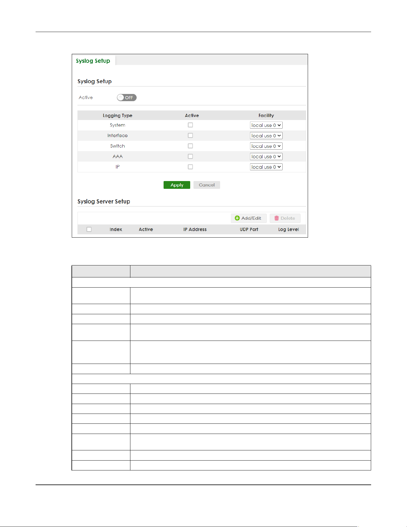
Chapter 29 Syslog Setup
XGS2220 Series User’s Guide
215
Figure 156 SYSTEM > Syslog Setup
The following table describes the labels in this screen.
Table 99 SYSTEM > Syslog Setup
LABEL DESCRIPTION
Syslog Setup
Active Enable the switch button to turn on syslog (system logging) and then configure the syslog
setting.
Logging Type This column displays the names of the categories of logs that the device can generate.
Active Select this option to set the device to generate logs for the corresponding category.
Facility The log facility allows you to send logs to different files in the syslog server. Refer to the
documentation of your syslog program for more details.
Apply Click Apply to save your changes to the Switch’s run-time memory. The Switch loses these
changes if it is turned off or loses power, so use the Save link on the top navigation panel to
save your changes to the non-volatile memory when you are done configuring.
Cancel Click Cancel to begin configuring this screen afresh.
Syslog Server Setup
Index This is the index number of a syslog server entry.
Active This field displays if the device is activated to send logs to the syslog server.
IP Address This field displays the IP address of the syslog server.
UDP Port This field displays the port of the syslog server.
Log Level This field displays the severity level of the logs that the device is to send to this syslog server.
Select an entry’s check box to select a specific entry. Otherwise, select the check box in the
table heading row to select all entries.
Add/Edit Click Add/Edit to add a new entry or edit a selected one.
Delete Click Delete to remove the selected entries.
Chapter 29 Syslog Setup
XGS2220 Series User’s Guide
216
29.2.1 Add/Edit a Syslog Server
Use this screen to configure an external syslog server.
Click Add/Edit, or select an entry and click Add/Edit in the SYSTEM > Syslog Setup screen to display this
screen.
Figure 157 SYSTEM > Syslog Setup > Add/Edit
The following table describes the labels in this screen.
Table 100 SYSTEM > Syslog Setup > Add/Edit
LABEL DESCRIPTION
Active Enable the switch button to have the device send logs to this syslog server. Clear the check
box if you want to create a syslog server entry but not have the device send logs to it (you
can edit the entry later).
Server Address Enter the IPv4 or IPv6 address of the syslog server.
UDP Port The default syslog server port is 514. If your syslog server uses a different port, configure the
one it uses here.
Log Level Select the severity levels of the logs that you want the device to send to this syslog server.
The lower the number, the more critical the logs are.
Apply Click Apply to save your changes to the Switch’s run-time memory. The Switch loses these
changes if it is turned off or loses power, so use the Save link on the top navigation panel to
save your changes to the non-volatile memory when you are done configuring.
Clear Click Clear to clear the fields to the factory defaults.
Cancel Click Cancel to not save the configuration you make and return to the last screen.
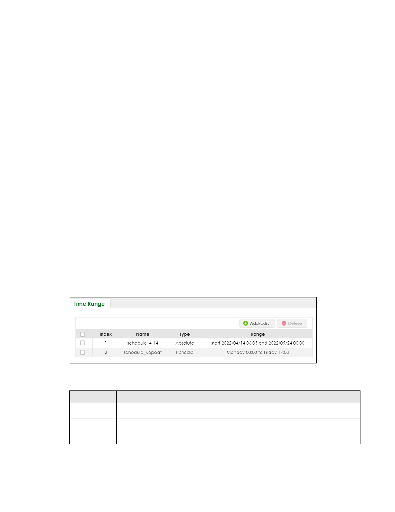
Chapter 30 Time Range
XGS2220 Series User’s Guide
217
CHAPTER 30
Time Range
30.1 Time Range Overview
You can set a time range for time-oriented features such as Classifier ACL (Access Control List) rule
which categorizes data packets into different network traffic flow. The advantage of the time range
feature is that it allows you to schedule the active time of configurations.
The time range can be configured in two ways – Absolute and Periodic. Absolute is a fixed time range
with a start and end time. Periodic is recurrence of a time range and does not have an end time.
30.1.1 What You Can Do
Use the Time Range screen (Section 30.2 on page 217) to view or define a schedule on the Switch.
30.2 Configuring Time Range
Click SYSTEM > Time Range in the navigation panel to display the screen as shown.
Figure 158 SYSTEM > Time Range
The following table describes the labels in this screen.
Table 101 SYSTEM > Time Range
LABEL DESCRIPTION
Select an entry’s check box to select a specific entry. Otherwise, select the check box in the
table heading row to select all entries.
Index This field displays the index number of the rule.
Name This field displays the descriptive name for this rule. This is for identification purpose only. You can
enter up to 32 printable ASCII characters except [ ? ], [ | ], [ ' ], [ " ] or [ , ].
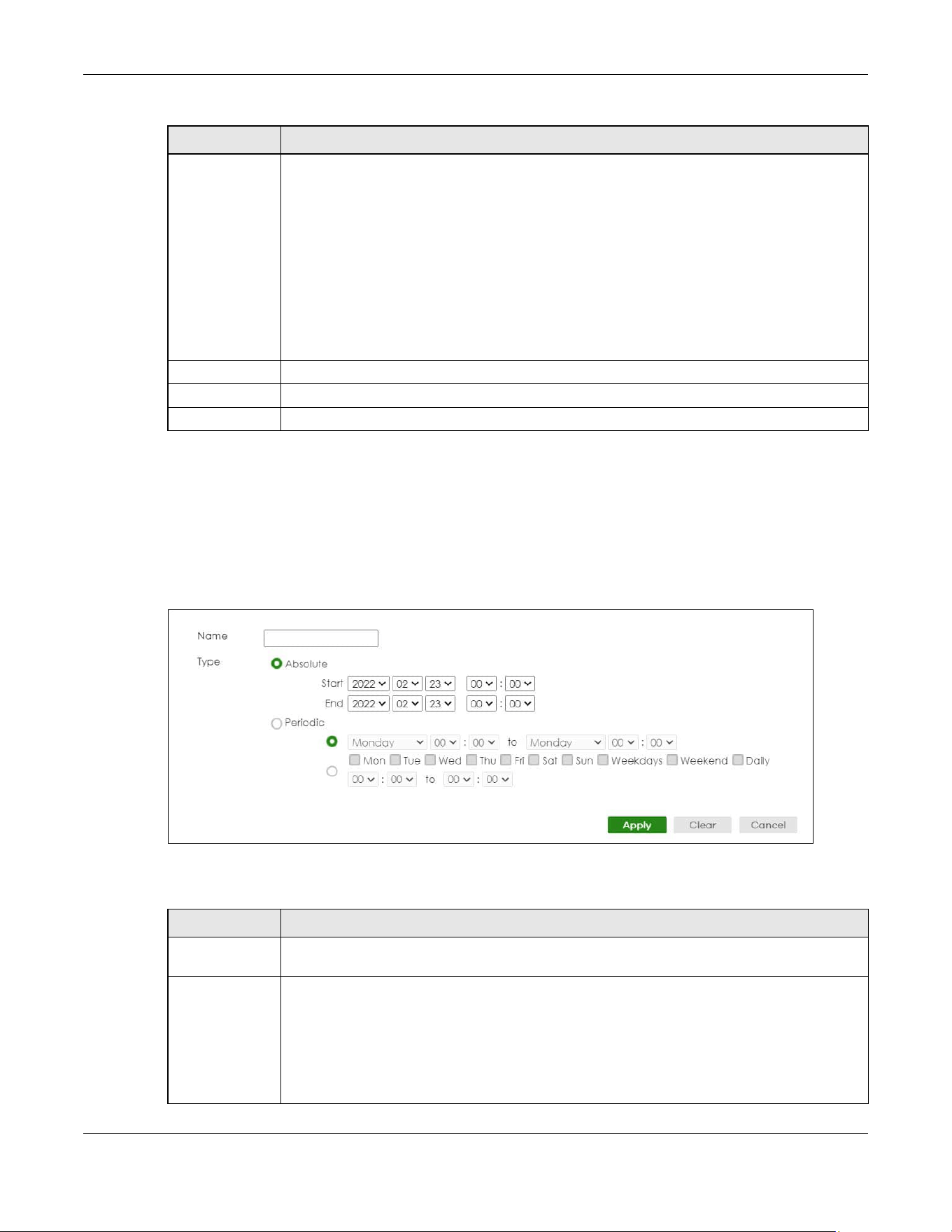
Chapter 30 Time Range
XGS2220 Series User’s Guide
218
30.2.1 Add/Edit Time Range
This screen allows you to create a new time range or edit an existing one.
To access this screen, click the Add/Edit button or select an entry from the list and click the Add/Edit
button.
Figure 159 SYSTEM > Time Range > Add/Edit
The following table describes the labels in this screen.
Type This displays the schedule type of the time range rule.
Absolute
An one-time schedule. One-time schedules begin on a specific start date and time and end on
a specific stop date and time. One-time schedules are useful for long holidays and vacation
periods.
Periodic
A recurring schedule. Recurring schedules begin at a specific start time and end at a specific
stop time on selected days of the week (Sunday, Monday, Tuesday, Wednesday, Thursday,
Friday, and Saturday). Recurring schedules are useful for defining the workday and off-work
hours.
Range This field displays the time periods to which this schedule applies.
Add/Edit Click Add/Edit to add a new schedule rule or edit a selected one.
Delete Click Delete to remove the selected rules.
Table 101 SYSTEM > Time Range (continued)
LABEL DESCRIPTION
Table 102 SYSTEM > Time Range > Add/Edit
LABEL DESCRIPTION
Name Enter a descriptive name for this rule for identifying purposes. The string should not contain [ ? ], [
| ], [ ' ], [ " ] or [ , ].
Type Select Absolute to create a one-time schedule. One-time schedules begin on a specific start
date and time and end on a specific stop date and time. One-time schedules are useful for
long holidays and vacation periods.
Alternatively, select Periodic to create a recurring schedule. Recurring schedules begin at a
specific start time and end at a specific stop time on selected days of the week (Sunday,
Monday, Tuesday, Wednesday, Thursday, Friday, and Saturday). Recurring schedules are useful
for defining the workday and off-work hours.

Chapter 30 Time Range
XGS2220 Series User’s Guide
219
Absolute This section is available only when you set Type to Absolute.
Start Specify the year, month, day, hour and minute when the schedule begins.
End Specify the year, month, day, hour and minute when the schedule ends.
Periodic This section is available only when you set Type to Periodic.
Select the first option if you want to define a recurring schedule for a consecutive time period.
You then select the day of the week, hour and minute when the schedule begins and ends
respectively.
Select the second option if you want to define a recurring schedule for multiple non-
consecutive time periods. You need to select each day of the week the recurring schedule is
effective. You also need to specify the hour and minute when the schedule begins and ends
each day. The schedule begins and ends in the same day.
Apply Click Apply to save your changes to the Switch’s run-time memory. The Switch loses these
changes if it is turned off or loses power, so use the Save link on the top navigation panel to save
your changes to the non-volatile memory when you are done configuring.
Clear Click Clear to clear the fields to the factory defaults.
Cancel Click Cancel to not save the configuration you make and return to the last screen.
Table 102 SYSTEM > Time Range > Add/Edit (continued)
LABEL DESCRIPTION

XGS2220 Series User’s Guide
220
CHAPTER 31
PORT
The following chapters introduces the configurations of the links under the PORT navigation panel.
Quick links to chapters:
• Auto PD Recovery (for PoE models only)
• Flex Link
• Green Ethernet
• Link Aggregation
• Link Layer Discovery Protocol (LLDP)
• OAM
• PoE Setup (for PoE models only)
• Port Setup
• ZULD
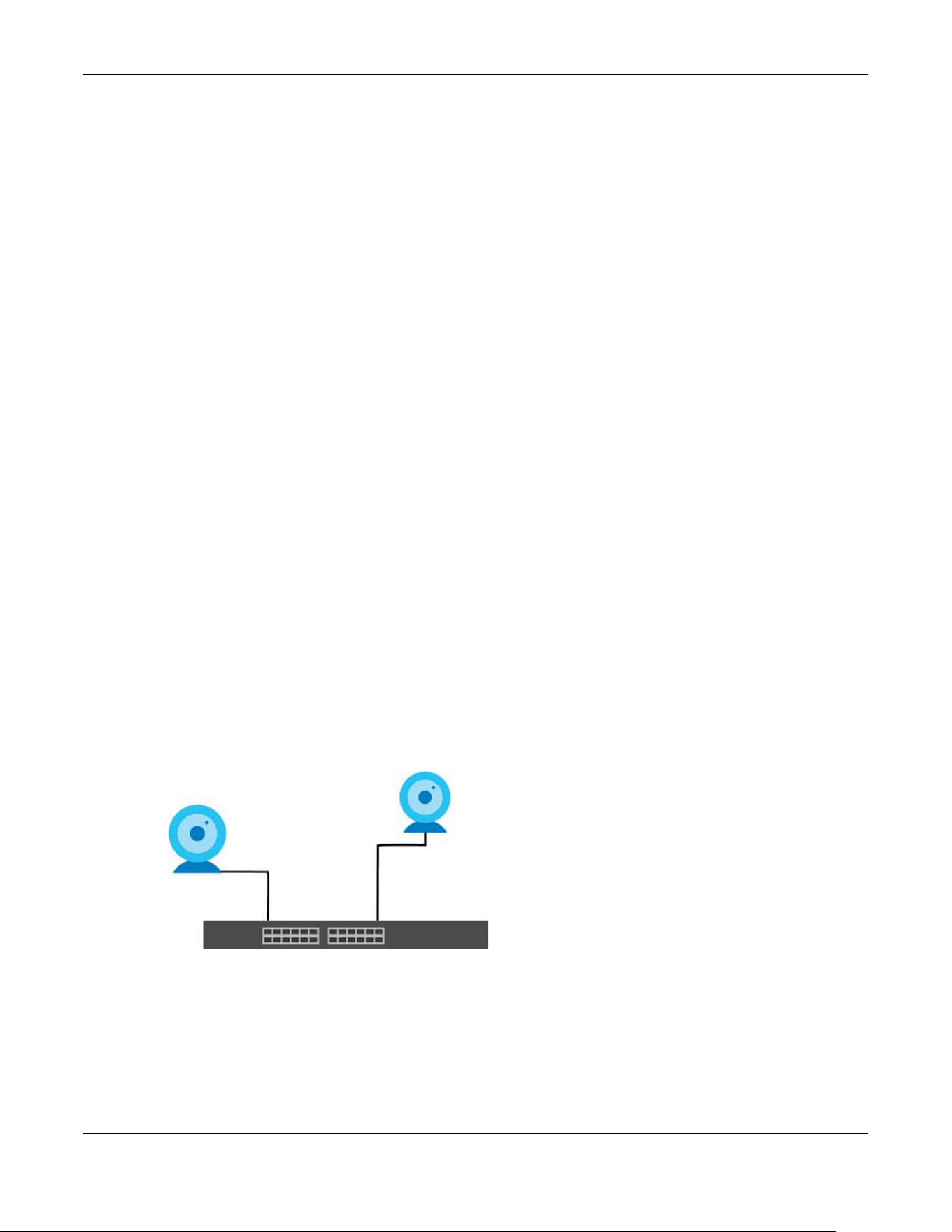
Chapter 32 Auto PD Recovery
XGS2220 Series User’s Guide
221
CHAPTER 32
Auto PD Recovery
32.1 Auto PD Recovery (for PoE models only) Overview
Things can go wrong with any network devices. A PD (for example, IP camera) may slow down or freeze
and need to be restarted if it is overworked or a bug causes a memory leak. When a connected PD
ceases to respond, Automatic PD Recovery allows the Switch to restart the PD by turning it off and on
without the need for on-site troubleshooting.
32.1.1 What You Can Do
Use the Auto PD Recovery screen (Section 32.2 on page 221) to enable and configure automatic PD
recovery on the Switch.
32.2 Auto PD Recovery
This screen lets you turn on automatic PD recovery on the Switch and its Ethernet ports. You can
configure whether the Switch uses LLDP or ping to check the current status of a connected PD.
The ping is sent through the Switch's default management IP address to the designated port. To ping the
PD, the port must share the same VLAN as the Switch's management VLAN.
Figure 160 Auto PD Recovery Application
The PD may stop responding to the Switch’s detection over ping or LLDP
during firmware upgrade. Disable the Auto PD Recovery function to
prevent damage to the PD caused by a power cutoff during firmware
upgrade.
Note: The following screens are available for the PoE models only.

Chapter 32 Auto PD Recovery
XGS2220 Series User’s Guide
222
To open this screen, click PORT > Auto PD Recovery.
Figure 161 PORT > Auto PD Recovery (Standalone Mode)
Figure 162 PORT > Auto PD Recovery (Stacking Mode)
The following table describes the labels in this screen.
Table 103 PORT > Auto PD Recovery
LABEL DESCRIPTION
Active Select this option to enable Auto PD Recovery on the Switch.
Slot This field appears only in Stacking mode. Click the drop-down list to choose the slot number of
the Switch in a stack.
Port This field displays the port number. In stacking mode, the first number represents the slot ID
and the second is the port number. Please note that the default stacking ports (the last two
ports of your Switch) cannot be configured. They are reserved for stacking only.
* Settings in this row apply to all ports.
Use this row only if you want to make some settings the same for all ports. Use this row first to
set the common settings and then make adjustments on a port-by-port basis.
Changes in this row are copied to all the ports as soon as you make them.
Active Select Active to enable Auto PD Recovery on the ports.

Chapter 32 Auto PD Recovery
XGS2220 Series User’s Guide
223
32.2.1 Activate the Automatic PD Recovery
Follow the steps below to activate the automatic PD recovery.
1 In the PORT > Auto PD Recovery screen, activate the feature.
Mode Select LLDP to have the Switch passively monitor current status of the connected PD by
reading LLDP packets from the PD on the port. The Switch also sends out LLDP packets to the
PD to update the Switch Neighbor table on the PD.
Select Ping to have the Switch ping the IP address of the connected PD to test whether the
PD is reachable or not.
Neighbor Name If Mode is set to LLDP, the system name of the connected PD displays automatically.
Neighbor IP If Mode is set to Ping and the PD supports LLDP, the connected PD’s IPv4 or IPv6 address to
which the Switch sends ping requests will display automatically. If not, enter the IP address
manually.
Test Click Test to have the Switch test the connection by sending a ping request to the IP address.
Polling Interval
(sec)
Specify the number of seconds the Switch waits for a response before sending another ping
request.
For example, the Switch will try to detect the PD status by performing ping requests every 20
seconds.
Polling Count Specify how many times the Switch is to resend a ping request before considering the PD
unreachable.
For example, If there is no ping reply from the PD after the Polling Interval (sec) has elapsed,
Polling Count starts from 1. After Polling Count reaches 3, the PD Health status LED will turn to
red in the MONITOR > Neighbor screen. The Switch will then perform your choice in the Action
field.
Action Set the action to take when the connected PD has stopped responding.
Select Reboot-Alarm to have the Switch turn OFF the power of the connected PD (the
connecting port is detected as link-down) and turn it back ON again to restart the PD after
sending an SNMP trap and generating a log message.
When restarting, the PD entry disappears from the Switch’s LLDP table and the PD Health
status LED will turn to yellow in the MONITOR > Neighbor screen.
Select Alarm to have the Switch send an SNMP trap and generate a log message.
Resume Polling
Interval (sec)
Specify the number of seconds the Switch waits before monitoring the PD status again after it
restarts the PD on the port.
PD Reboot Count Specify how many times the Switch attempts to restart the PD on the port.
The PD Reboot Count will reset
• as soon as a ping is successful,
• or when any modification to the Auto PD Recovery screen is applied,
• or after restarting the Switch.
Resume Power
Interval (sec)
Specify the number of seconds the Switch waits before supplying power to the connected PD
again after it restarts the PD on the port.
Apply Click Apply to save your changes to the Switch’s run-time memory. The Switch loses these
changes if it is turned off or loses power, so use the Save link on the top navigation panel to
save your changes to the non-volatile memory when you are done configuring.
Cancel Click this to reset the values in this screen to their last-saved values.
Table 103 PORT > Auto PD Recovery (continued)
LABEL DESCRIPTION
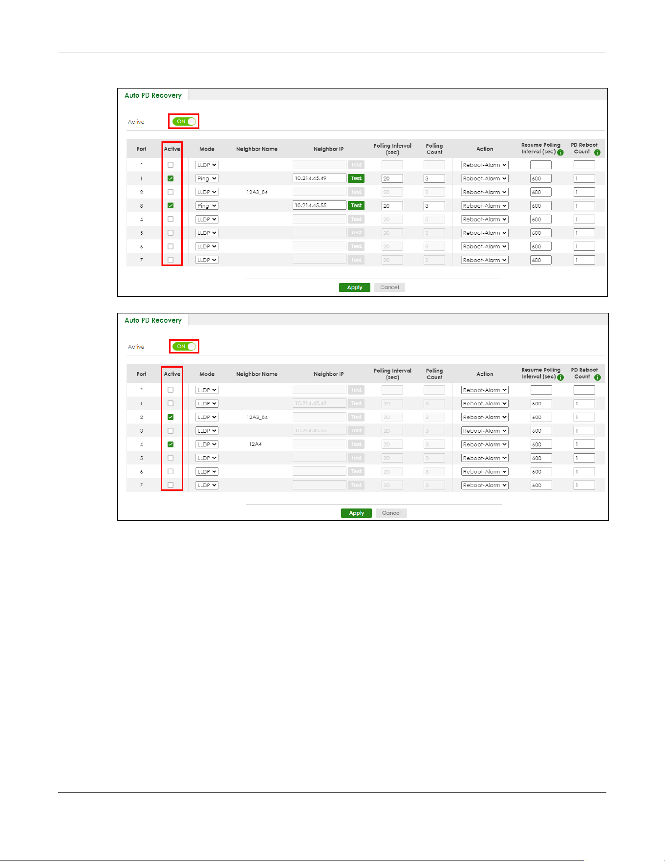
Chapter 32 Auto PD Recovery
XGS2220 Series User’s Guide
224
Figure 163 Auto PD Recovery (Ping Mode)
Figure 164 Auto PD Recovery (LLDP Mode)
2 Select the desired ports in the Active column.
3 Select the Mode.
When you select Ping, the connected PD’s IPv4 or IPv6 address to which the Switch sends ping requests
will display automatically if the PD supports LLDP. If not, enter the IP address of the PDs in the Neighbor IP
field.
The default setting for Polling Interval (sec) (20 secs) and Polling Count (3 times) will cause the Switch to
ping the PD status every 20 seconds. If there is no ping reply from the PD, Polling Count starts to count
from 1. Once Polling Count reaches 3, the Switch will cause a Reboot-Alarm on the PD as selected in
Action.
When you select LLDP, the Switch monitors the PD status by checking incoming LLDP packets every 30
seconds from the PD (default value of transmit interval for LLDP feature).
Likewise, the Switch sends out LLDP packets to the PD every 30 seconds to update the MONITOR >
Neighbor screen.

Chapter 32 Auto PD Recovery
XGS2220 Series User’s Guide
225
Once the LLDP table’s counter reaches the default 120 seconds, the Switch will cause a Reboot-Alarm
on the PD as selected in Action.
4 After sending an SNMP trap and generating a log message, the connected PD will restart (the
connecting port is detected as link-down).
When restarting, the PD entry disappears from the Switch’s LLDP table and the PD Health status LED will
turn to yellow in the MONITOR > Neighbor screen.
After the PD is powered on, the Switch resumes detection of the PD status by performing ping requests
or checking the LLDP table based on your value for Resume Polling Interval.
When the PD Reboot Count value is reached, the Switch will no longer perform the PD recovery process.
The PD Health status LED will turn to red in the MONITOR > Neighbor screen.
5 Click Apply to save your changes back to the run-time memory.
6 Click the Save link in the upper right corner of the Web Configurator to save your configuration
permanently.
Note: In the event of a PD performing firmware upgrade, the PD may stop responding to ping
or fail to provide LLDP packets for an extended period of time. When the Switch resets
power to the PD before firmware upgrade is finished, it may permanently damage the
PD or require a hard reset to recover it. It is strongly advised to disable the Switch's Auto
PD Recovery function before upgrading the PD's firmware. This will prevent damage
caused by a power cutoff.

Chapter 33 Flex Link
XGS2220 Series User’s Guide
226
CHAPTER 33
Flex Link
This chapter introduces how to set up a backup link for a primary link using Flex Links.
33.1 Flex Link Overview
A flex link pair consists of a primary link and a backup link on a layer-2 interface. A primary link runs on a
Primary Port; a backup link runs on a Backup Port. The ports have two states: FORWARDING and
BLOCKING. When one link is up and running (port state: FORWARDING), the other link is in down or in
standby mode (port state: BLOCKING). Only one port is forwarding traffic (FORWARDING) at a time.
When the primary link goes down, the backup link automatically goes up and is able to forward traffic.
Preemption
Enable Preemption to have the Switch automatically return the primary port to FORWARDING state after
the connection from the primary port resumes, and the backup port return to BLOCKING. The Switch will
wait for the specified Preemption Delay Time before changing the primary port state to FORWARDING
and backup port state to BLOCKING. See Table 106 on page 229 for more information.
33.1.1 What You Can Do
• Use the Flex Link Status screen (Section 33.2 on page 226) to view the flex link status on the Switch.
• Use the Flex Link Setup screen (Section 33.3 on page 227) to configure flex links for back up links on
the Switch.
33.2 Flex Link Status
Click PORT > Flex Link > Flex Link Status to display this screen.
Figure 165 PORT > Flex Link > Flex Link Status

Chapter 33 Flex Link
XGS2220 Series User’s Guide
227
The following table describes the labels in this screen.
33.3 Flex Link Setup
Click PORT > Flex Link > Flex Link Setup to display this screen.
Note: The Flex Link (PORT > Flex Link), STP (SWITCHING > Spanning Tree Protocol), Loop Guard
(SWITCHING > Loop Guard) and Link Aggregation (PORT > Link Aggregation) features
cannot be configured together on the same port. When one of the above functions is
enabled, the Switch will not let you enable the others.
Note: You can configure up to five pairs of flex links.
Figure 166 PORT > Flex Link > Flex Link Setup
The following table describes the labels in this screen.
Table 104 PORT > Flex Link > Flex Link Status
LABEL DESCRIPTION
Index This displays the index number of a flex link pair.
Primary Port This displays the port number of the primary link.
In Stacking mode, the first number represents the slot ID and the second is the port number.
Backup Port This displays the port number of the backup link.
In Stacking mode, the first number represents the slot ID and the second is the port number.
State This displays the link status of the Primary port and Backup port.
Down – The link is down.
Up – The link is up and the port state is FORWARDING.
Standby – The link is up and the port state is BLOCKING.
Note: Only one port can be up in a flex link pair.
Table 105 PORT > Flex Link > Flex Link Setup
LABEL DESCRIPTION
Index This displays the index number of an entry.
Primary Port This displays the port number of the primary link.
In Stacking mode, the first number represents the slot ID and the second is the port number.
Backup Port This displays the port number of the backup link.
In Stacking mode, the first number represents the slot ID and the second is the port number.
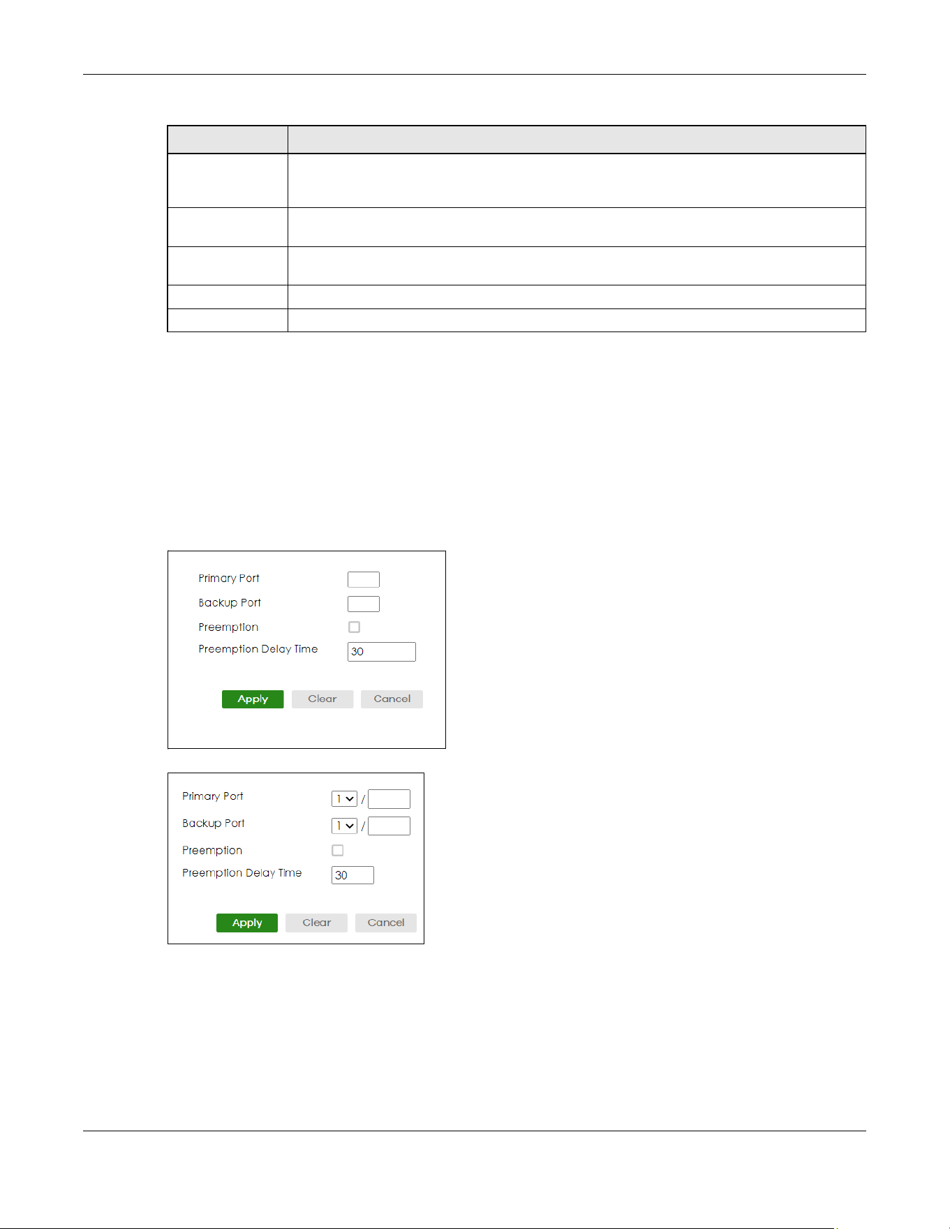
Chapter 33 Flex Link
XGS2220 Series User’s Guide
228
33.3.1 Add/Edit Flex Link
To access this screen, click the Add/Edit button or select an entry from the list and click the Add/Edit
button.
Note: A port can only be in one flex link pair. If a port has already been set as a flex link pair’s
primary/backup port, the port can not be used by other flex links. Check the PORT >
Flex Link > Flex Link Setup screen to see what ports are already in other flex link pairs.
Figure 167 PORT > Flex Link > Flex Link Setup > Add/Edit (Standalone Mode)
Figure 168 PORT > Flex Link > Flex Link Setup > Add/Edit (Stacking Mode)
Preemption This displays if Preemption is enabled on the flex link pair. If Preemption is enabled, when the
primary port comes back up, the backup port will go into BLOCKING state and the primary
port will go into FORWARDING state after the Preemption Delay Time interval.
Preemption Delay
Time
This displays the preemption delay time configured for this flex link pair.
Select an entry’s check box to select a specific entry. Otherwise, select the check box in the
table heading row to select all entries.
Add/Edit Click Add/Edit to add a new entry or edit a selected one.
Delete Click Delete to remove the selected entry.
Table 105 PORT > Flex Link > Flex Link Setup (continued)
LABEL DESCRIPTION
Chapter 33 Flex Link
XGS2220 Series User’s Guide
229
The following table describes the labels in this screen.
Table 106 PORT > Flex Link > Flex Link Setup > Add/Edit
LABEL DESCRIPTION
Primary Port Enter a port number to be the primary port.
In Stacking mode, the first field is the slot ID and the second field is the port number.
Please note that the default stacking ports (the last four ports of your Switch) cannot be
configured. They are reserved for stacking only.
Backup Port Enter a port number to be the backup port.
In Stacking mode, the first field is the slot ID and the second field is the port number.
Please note that the default stacking ports (the last four ports of your Switch) cannot be
configured. They are reserved for stacking only.
Preemption Select this to enable the Preemption mode on the flex link pair.
If Preemption is disabled, if the primary port is down, then comes back up, it will remain in the
BLOCKING state even after the Preemption Delay Time.
Preemption Delay
Time
Enter the delay time (in seconds) which you want the primary port to wait before changing
back to FORWARDING state (when available). The range is 1 – 300 seconds.
Apply Click Apply to save your changes to the Switch’s run-time memory. The Switch loses these
changes if it is turned off or loses power, so use the Save link on the top navigation panel to
save your changes to the non-volatile memory when you are done configuring.
Clear Click Clear to clear the fields to the factory defaults.
Cancel Click Cancel to not save the configuration you make and return to the last screen.

Chapter 34 Green Ethernet
XGS2220 Series User’s Guide
230
CHAPTER 34
Green Ethernet
This chapter shows you how to configure the Switch to reduce the power consumed by switch ports.
34.1 Green Ethernet Overview
Green Ethernet reduces switch port power consumption in the following ways.
IEEE 802.3az Energy Efficient Ethernet (EEE)
If EEE is enabled, both sides of a link support EEE and there is no traffic, the port enters Low Power Idle
(LPI) mode. LPI mode turns off some functions of the physical layer (becomes quiet) to save power.
Periodically the port transmits a REFRESH signal to allow the link partner to keep the link alive. When there
is traffic to be sent, a WAKE signal is sent to the link partner to return the link to active mode.
Auto Power Down
Auto Power Down turns off almost all functions of the port’s physical layer functions when the link is
down, so the port only uses power to check for a link up pulse from the link partner. After the link up
pulse is detected, the port wakes up from Auto Power Down and operates normally.
Short Reach
Traditional Ethernet transmits all data with enough power to reach the maximum cable length. Shorter
cables lose less power, so Short Reach saves power by adjusting the transmit power of each port
according to the length of cable attached to that port.
34.2 Configuring Green Ethernet
Click PORT > Green Ethernet in the navigation panel to display the screen as shown.
Note: This feature is only available on copper ports. Check boxes of SFP ports are grayed out
and cannot be selected.
Note: EEE, Auto Power Down and Short Reach are NOT supported on an uplink port.
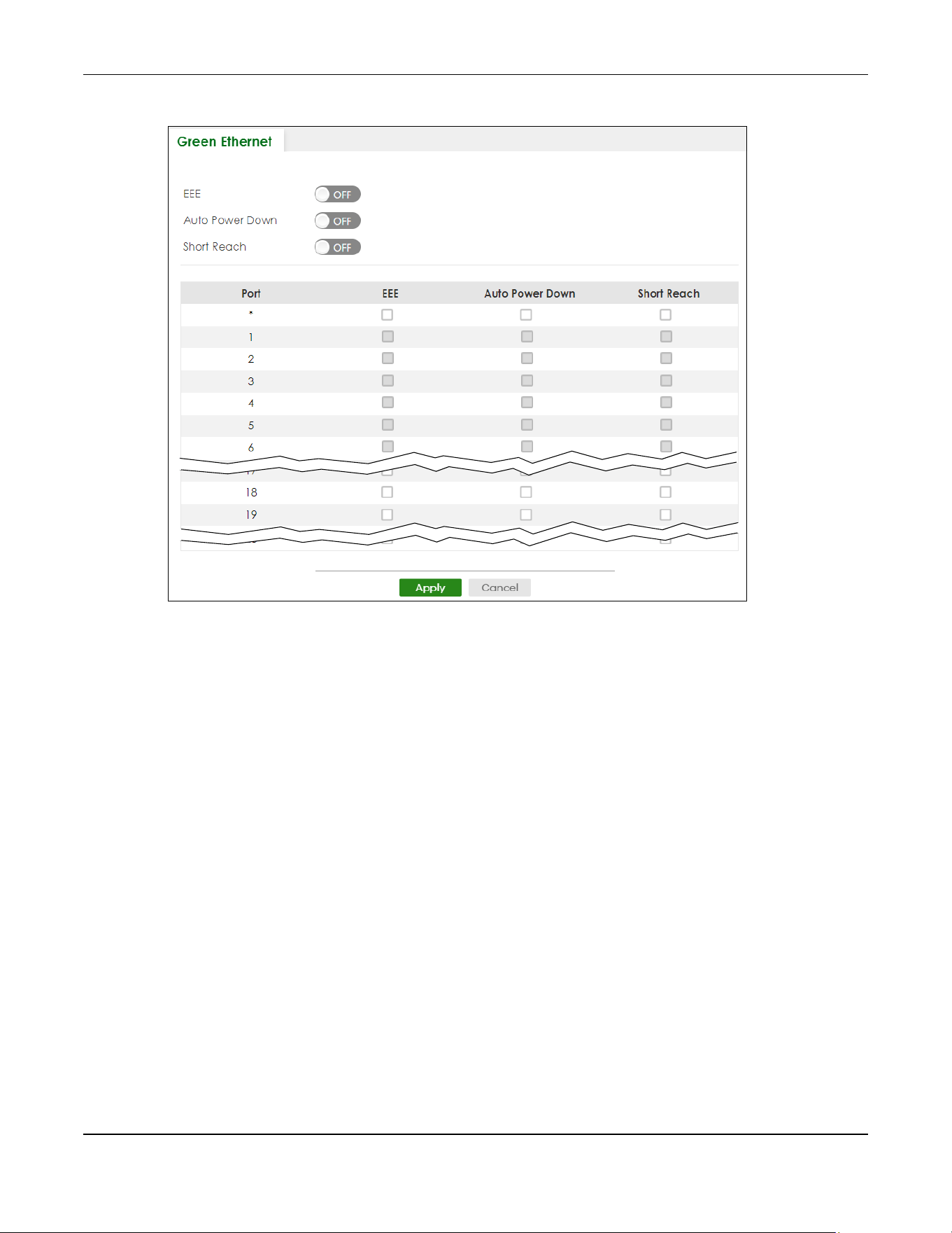
Chapter 34 Green Ethernet
XGS2220 Series User’s Guide
231
Figure 169 PORT > Green Ethernet (Standalone Mode)

Chapter 34 Green Ethernet
XGS2220 Series User’s Guide
232
Figure 170 PORT > Green Ethernet (Stacking Mode)
The following table describes the labels in this screen.
Table 107 PORT > Green Ethernet
LABEL DESCRIPTION
EEE Enable the switch button to activate Energy Efficient Ethernet globally.
Auto Power
Down
Enable the switch button to activate Auto Power Down globally.
Short Reach Enable the switch button to activate Short Reach globally.
SLOT This field appears only in Stacking mode. Click the drop-down list to choose the slot number of
the Switch in a stack.
Port This field displays the port number. In Stacking mode, the first number represents the slot ID and
the second is the port number. Please note that the default stacking ports (the last four ports of
your Switch) cannot be configured. They are reserved for stacking only.
* Use this row to make the setting the same for all ports. Use this row first and then make
adjustments to each port if necessary.
Changes in this row are copied to all the ports as soon as you make them.
EEE Select this to activate Energy Efficient Ethernet on this port.
Auto Power
Down
Select this to activate Auto Power Down on this port.
Short Reach Select this to activate Short Reach on this port.

Chapter 34 Green Ethernet
XGS2220 Series User’s Guide
233
Apply Click Apply to save your changes to the Switch’s run-time memory. The Switch loses these
changes if it is turned off or loses power, so use the Save link on the top navigation panel to save
your changes to the non-volatile memory when you are done configuring.
Cancel Click Cancel to begin configuring this screen afresh.
Table 107 PORT > Green Ethernet (continued)
LABEL DESCRIPTION

Chapter 35 Link Aggregation
XGS2220 Series User’s Guide
234
CHAPTER 35
Link Aggregation
35.1 Link Aggregation Overview
This chapter shows you how to logically aggregate physical links to form one logical, higher-bandwidth
link.
Link aggregation (trunking) is the grouping of physical ports into one logical higher-capacity link. You
may want to trunk ports if for example, it is cheaper to use multiple lower-speed links than to under-utilize
a high-speed, but more costly, single-port link. However, the more ports you aggregate then the fewer
available ports you have. A trunk group is one logical link containing multiple ports.
The beginning port of each trunk group must be physically connected to form a trunk group.
35.1.1 What You Can Do
• Use the Link Aggregation Status screen (Section 35.2 on page 236) to view ports you have configured
to be in the trunk group, ports that are currently transmitting data as one logical link in the trunk group
and so on.
• Use the Link Aggregation Setting screen (Section 35.3 on page 237) to configure static link
aggregation.
• Use the Link Aggregation Control Protocol screen (Section 35.4 on page 240) to enable Link
Aggregation Control Protocol (LACP).
35.1.2 What You Need to Know
The Switch supports both static and dynamic link aggregation.
Note: In a properly planned network, it is recommended to implement static link aggregation
only. This ensures increased network stability and control over the trunk groups on your
Switch.
See Section 35.5.1 on page 243 for a static port trunking example.
Dynamic Link Aggregation
The Switch adheres to the IEEE 802.3ad standard for static and dynamic (LACP) port trunking.
The IEEE 802.3ad standard describes the Link Aggregation Control Protocol (LACP) for dynamically
creating and managing trunk groups.
When you enable LACP link aggregation on a port, the port can automatically negotiate with the ports
at the remote end of a link to establish trunk groups. LACP also allows port redundancy, that is, if an
Chapter 35 Link Aggregation
XGS2220 Series User’s Guide
235
operational port fails, then one of the “standby” ports become operational without user intervention.
Please note that:
• You must connect all ports point-to-point to the same Ethernet switch and configure the ports for
LACP trunking.
• LACP only works on full-duplex links.
• All ports in the same trunk group must have the same media type, speed, duplex mode and flow
control settings.
Configure trunk groups or LACP before you connect the Ethernet switch to avoid causing network
topology loops.
Link Aggregation ID
LACP aggregation ID consists of the following information
1
:
Traffic Distribution Criteria
The Switch supports both unicast and non-unicast traffic (broadcast and multicast) network load sharing
over link aggregation. Load sharing works by statically splitting the traffic based on source or destination
IP/MAC address, and then distributing the load across multiple paths. In link aggregation, this allows the
trunk group (ports) to transmit data as one logical link to a single or group of hosts on the network.
Unicast and non-unicast traffic network load sharing over link aggregation (trunking) is enabled by
default.
Algorithm Types Limitation
The maximum number of link aggregation algorithm types (Criteria) that can link up at the same time
depends on your Switch model. See Table 111 on page 236 for the list of Criteria that your Switch
currently supports.
The following table shows the maximum number of link aggregation algorithm types that can link up at
the same time.
Table 108 Link Aggregation ID: Local Switch
SYSTEM PRIORITY MAC ADDRESS KEY PORT PRIORITY PORT NUMBER
0000 00-00-00-00-00-00 0000 00 0000
Table 109 Link Aggregation ID: Peer Switch
SYSTEM PRIORITY MAC ADDRESS KEY PORT PRIORITY PORT NUMBER
0000 00-00-00-00-00-00 0000 00 0000
1. Port Priority and Port Number are 0 as it is the aggregator ID for the trunk group, not the individual port.
Table 110 Link Aggregation Algorithm Types Limitation
MODEL LINK AGGREGATION ALGORITHM TYPES (MAXIMUM)
XGS2220 Series 2

Chapter 35 Link Aggregation
XGS2220 Series User’s Guide
236
For example, if your Switch has two link aggregation algorithm types that are currently online. The third
link aggregation algorithm type can only go online when one of the online link aggregation algorithm
type goes offline.
In stacking mode, the stacking channel is using link-aggregation. The default algorithm type is src-dst-
mac, and is not configurable. Therefore, you have only one other algorithm type that can link up at the
same time.
By default, the stacking ports are trunk ports. For example, for a 54-port Switch, the stacking ports 51 and
52, 53 and 54 are two trunk groups.
35.2 Link Aggregation Status
Click PORT > Link Aggregation > Link Aggregation Status in the navigation panel to display the screen as
shown. See Section 35.1 on page 234 for more information.
Figure 171 PORT > Link Aggregation > Link Aggregation Status
The following table describes the labels in this screen.
Table 111 PORT > Link Aggregation > Link Aggregation Status
LABEL DESCRIPTION
Group ID This field displays the group ID to identify a trunk group, that is, one logical link containing multiple
ports.
Enabled Ports These are the ports you have configured in the Link Aggregation Setting screen to be in the trunk
group.
The port numbers displays only when this trunk group is activated and there is a port belonging to
this group.
Synchronized
Ports
These are the ports that are currently transmitting data as one logical link in this trunk group.
Aggregator ID Link Aggregator ID consists of the following: system priority, MAC address, key, port priority and
port number.
The ID displays only when there is a port belonging to this trunk group and LACP is also enabled
for this group.

Chapter 35 Link Aggregation
XGS2220 Series User’s Guide
237
35.3 Link Aggregation Setting
Click PORT > Link Aggregation > Link Aggregation Setting to display the screen shown next. See Section
35.1 on page 234 for more information on link aggregation.
Criteria This shows the outgoing traffic distribution algorithm types used in this trunk group. Sending of
packets are from the same source and/or to the same destination over the same link within the
trunk.
src-mac means the Switch distributes traffic based on the packet’s source MAC address.
dst-mac means the Switch distributes traffic based on the packet’s destination MAC address.
src-dst-mac means the Switch distributes traffic based on a combination of the packet’s source
and destination MAC addresses.
src-ip means the Switch distributes traffic based on the packet’s source IP address.
dst-ip means the Switch distributes traffic based on the packet’s destination IP address.
src-dst-ip means the Switch distributes traffic based on a combination of the packet’s source
and destination IP addresses.
Note: To find the number of link aggregation algorithm types that can link up at the
same time, see Algorithm Types Limitation on page 235.
Status This field displays how these ports were added to the trunk group. It displays:
• Static – if the ports are configured as static members of a trunk group.
• LACP – if the ports are configured to join a trunk group through LACP.
Table 111 PORT > Link Aggregation > Link Aggregation Status (continued)
LABEL DESCRIPTION
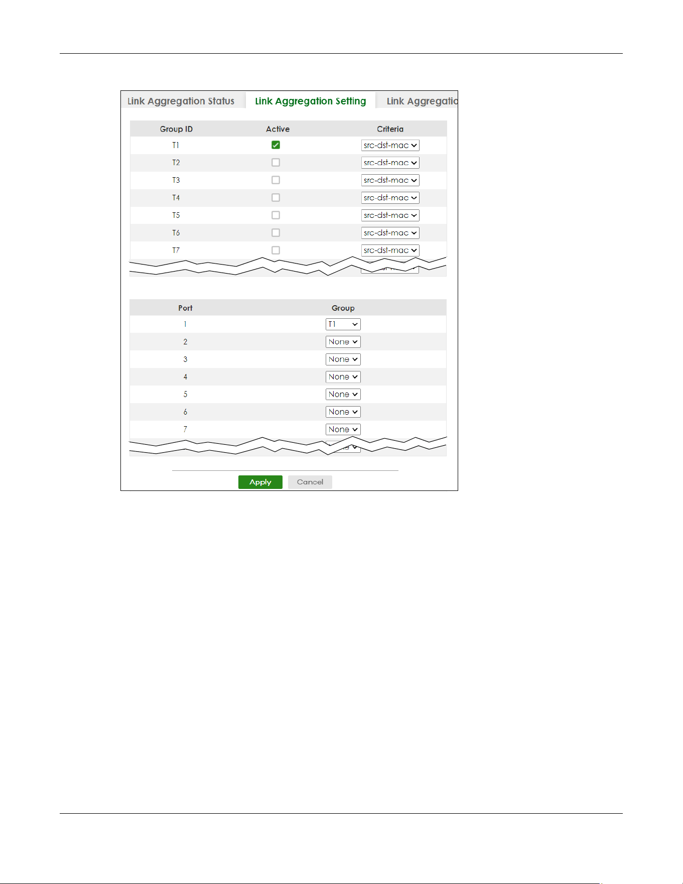
Chapter 35 Link Aggregation
XGS2220 Series User’s Guide
238
Figure 172 PORT > Link Aggregation > Link Aggregation Setting (Standalone Mode)

Chapter 35 Link Aggregation
XGS2220 Series User’s Guide
239
Figure 173 PORT > Link Aggregation > Link Aggregation Setting (Stacking Mode)
The following table describes the labels in this screen.
Table 112 PORT > Link Aggregation > Link Aggregation Setting
LABEL DESCRIPTION
This is the only screen you need to configure to enable static link aggregation.
Group ID The field identifies the link aggregation group, that is, one logical link containing multiple ports.
Active Select this to activate a trunk group.

Chapter 35 Link Aggregation
XGS2220 Series User’s Guide
240
35.4 Link Aggregation Control Protocol
Click PORT > Link Aggregation > Link Aggregation Control Protocol to display the screen shown next. See
Dynamic Link Aggregation on page 234 for more information on dynamic link aggregation.
Note: Do NOT configure this screen unless you want to enable dynamic link aggregation.
Criteria Select the outgoing traffic distribution type. Packets from the same source and/or to the same
destination are sent over the same link within the trunk. By default, the Switch uses the src-dst-mac
distribution type. If the Switch is behind a router, the packet’s destination or source MAC address
will be changed. In this case, set the Switch to distribute traffic based on its IP address to make
sure port trunking can work properly.
Select src-mac to distribute traffic based on the packet’s source MAC address.
Select dst-mac to distribute traffic based on the packet’s destination MAC address.
Select src-dst-mac to distribute traffic based on a combination of the packet’s source and
destination MAC addresses.
Select src-ip to distribute traffic based on the packet’s source IP address.
Select dst-ip to distribute traffic based on the packet’s destination IP address.
Select src-dst-ip to distribute traffic based on a combination of the packet’s source and
destination IP addresses.
SLOT This field appears only in Stacking mode. Click the drop-down list to choose the slot number of the
Switch in a stack.
Port This field displays the port number. In Stacking mode, the first number represents the slot ID and
the second is the port number. Please note that the default stacking ports (the last four ports of
your Switch) cannot be configured. They are reserved for stacking only.
Group Select the trunk group to which a port belongs.
Note: When you enable the port security feature on the Switch and configure port
security settings for a port, you cannot include the port in an active trunk group.
Apply Click Apply to save your changes to the Switch’s run-time memory. The Switch loses these
changes if it is turned off or loses power, so use the Save link on the top navigation panel to save
your changes to the non-volatile memory when you are done configuring.
Cancel Click Cancel to begin configuring this screen afresh.
Table 112 PORT > Link Aggregation > Link Aggregation Setting (continued)
LABEL DESCRIPTION

Chapter 35 Link Aggregation
XGS2220 Series User’s Guide
241
Figure 174 PORT > Link Aggregation > Link Aggregation Control Protocol (Standalone Mode)
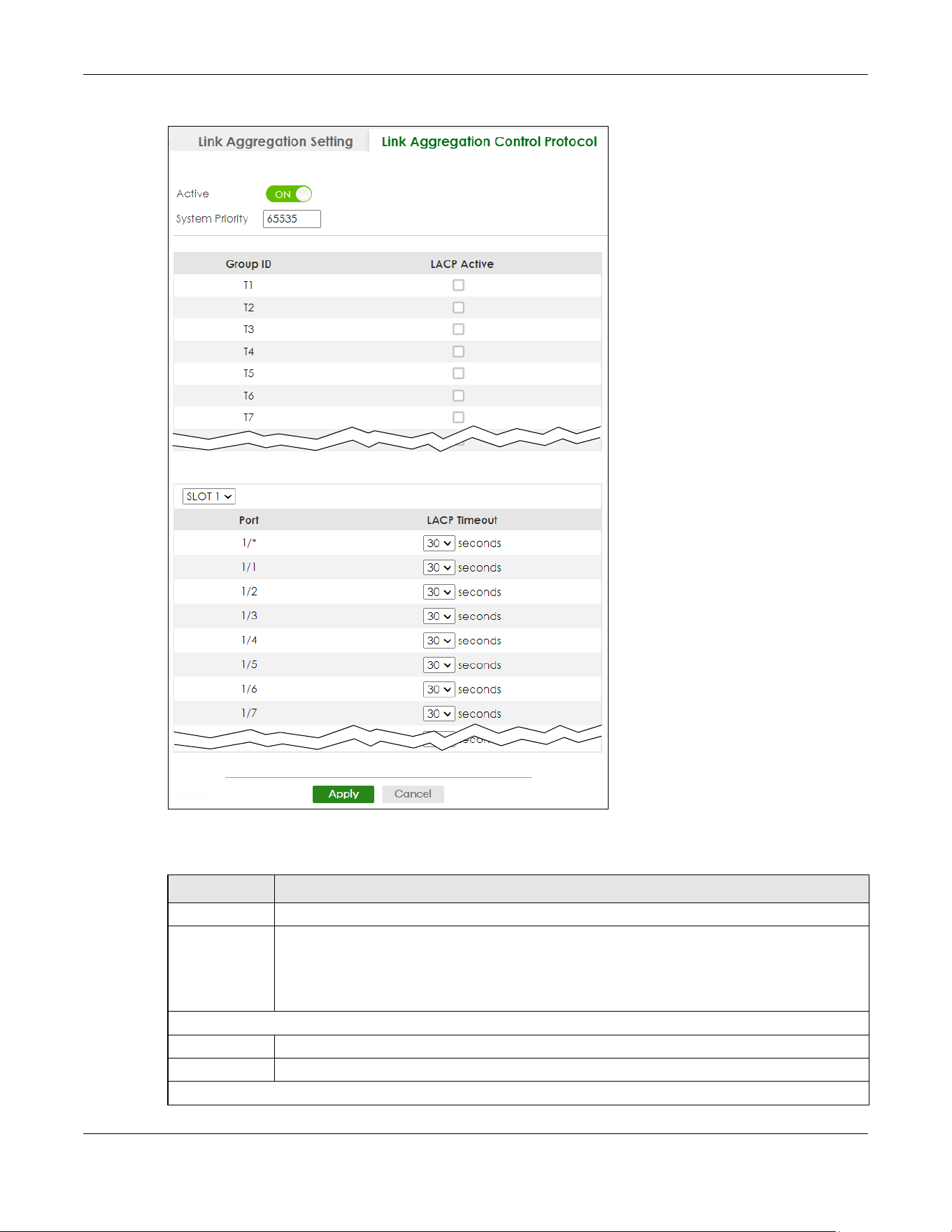
Chapter 35 Link Aggregation
XGS2220 Series User’s Guide
242
Figure 175 PORT > Link Aggregation > Link Aggregation Control Protocol (Stacking Mode)
The following table describes the labels in this screen.
Table 113 PORT > Link Aggregation > Link Aggregation Control Protocol
LABEL DESCRIPTION
Active Enable the switch button to enable Link Aggregation Control Protocol (LACP).
System Priority LACP system priority is a number between 1 and 65535. The switch with the lowest system priority
(and lowest port number if system priority is the same) becomes the LACP “server”. The LACP
“server” controls the operation of LACP setup. Enter a number to set the priority of an active port
using Link Aggregation Control Protocol (LACP). The smaller the number, the higher the priority
level.
Use this section to enable LACP on trunks.
Group ID The field identifies the link aggregation group, that is, one logical link containing multiple ports.
LACP Active Select this option to enable LACP for a trunk.
Use this section to configure LACP timeout on ports.
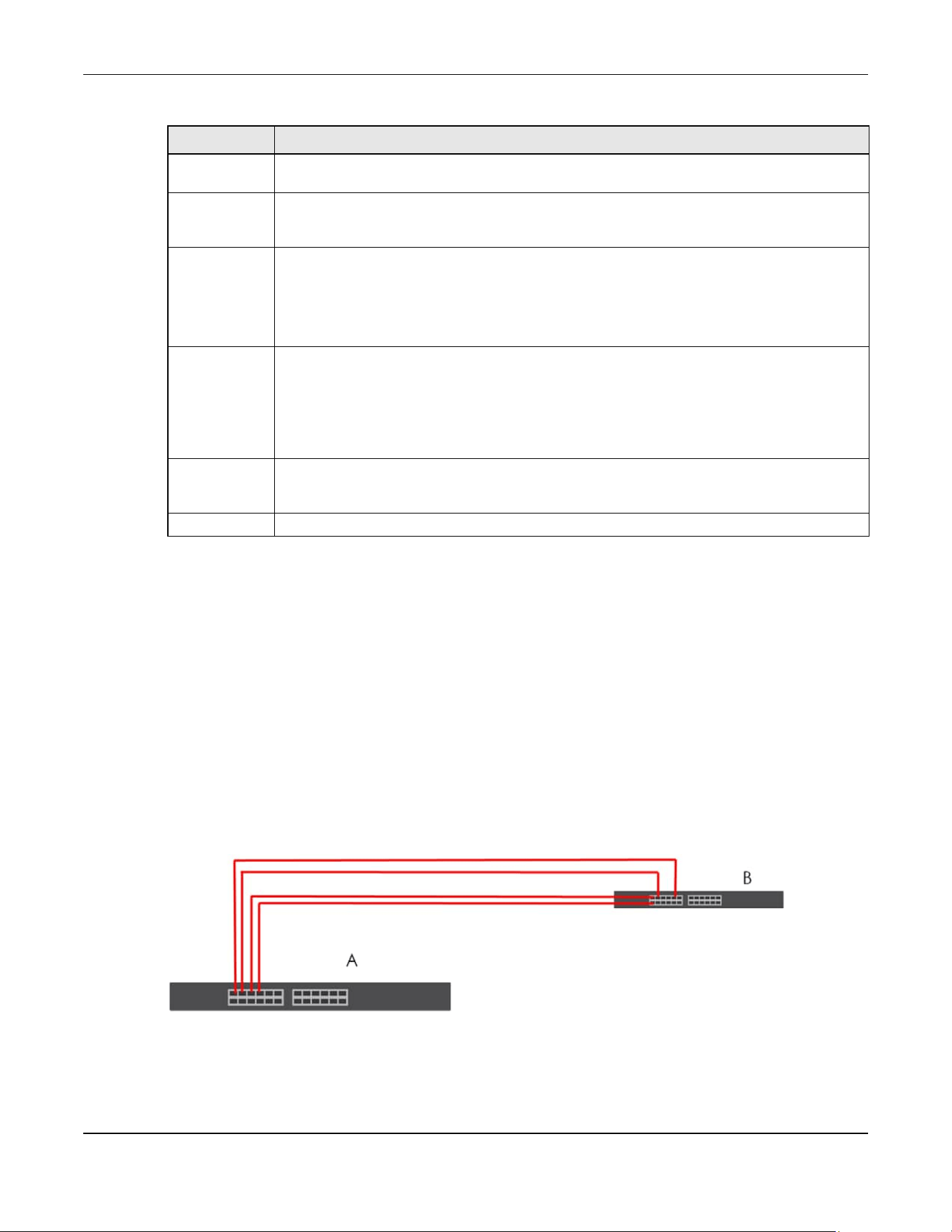
Chapter 35 Link Aggregation
XGS2220 Series User’s Guide
243
35.5 Technical Reference
This section provides technical background information on the topics discussed in this chapter.
35.5.1 Static Trunking Example
This example shows you how to create a static port trunk group for ports 2 – 5.
1 Make your physical connections – make sure that the ports that you want to belong to the trunk group
are connected to the same destination. The following figure shows ports 2 – 5 on switch A connected to
switch B.
Figure 176 Trunking Example
– Physical Connections
2 Configure static trunking – Click PORT > Link Aggregation > Link Aggregation Setting. In this screen
activate trunk group T1, select the traffic distribution algorithm used by this group and select the ports
that should belong to this group as shown in the figure below. Click Apply when you are done.
SLOT This field appears only in Stacking mode. Click the drop-down list to choose the slot number of the
Switch in a stack.
Port This field displays the port number. In Stacking mode, the first number represents the slot ID and
the second is the port number. Please note that the default stacking ports (the last four ports of
your Switch) cannot be configured. They are reserved for stacking only.
* Settings in this row apply to all ports.
Use this row only if you want to make some settings the same for all ports. Use this row first to set
the common settings and then make adjustments on a port-by-port basis.
Note: Changes in this row are copied to all the ports as soon as you make them.
LACP Timeout Timeout is the time interval between the individual port exchanges of LACP packets in order to
check that the peer port in the trunk group is still up. If a port does not respond after three tries,
then it is deemed to be “down” and is removed from the trunk. Set a short timeout (1 second) for
busy trunked links to ensure that disabled ports are removed from the trunk group as soon as
possible.
Select either 1 second or 30 seconds.
Apply Click Apply to save your changes to the Switch’s run-time memory. The Switch loses these
changes if it is turned off or loses power, so use the Save link on the top navigation panel to save
your changes to the non-volatile memory when you are done configuring.
Cancel Click Cancel to begin configuring this screen afresh.
Table 113 PORT > Link Aggregation > Link Aggregation Control Protocol (continued)
LABEL DESCRIPTION

Chapter 35 Link Aggregation
XGS2220 Series User’s Guide
244
Figure 177 Trunking Example – Configuration Screen
Your trunk group 1 (T1) configuration is now complete.

Chapter 36 Link Layer Discovery Protocol (LLDP)
XGS2220 Series User’s Guide
245
CHAPTER 36
Link Layer Discovery Protocol
(LLDP)
36.1 LLDP Overview
The LLDP (Link Layer Discovery Protocol) is a layer 2 protocol. It allows a network device to advertise its
identity and capabilities on the local network. It also allows the device to maintain and store information
from adjacent devices which are directly connected to the network device. This helps an administrator
discover network changes and perform necessary network reconfiguration and management. The
device information is encapsulated in the LLDPDUs (LLDP data units) in the form of TLV (Type, Length,
Value). Device information carried in the received LLDPDUs is stored in the standard MIB.
The Switch supports these basic management TLVs.
• End of LLDPDU (mandatory)
•Chassis ID (mandatory)
•Port ID (mandatory)
• Time to Live (mandatory)
• Port Description (optional)
• System Name (optional)
• System Description (optional)
• System Capabilities (optional)
• Management Address (optional)
The Switch also supports the IEEE 802.1 and IEEE 802.3 organizationally-specific TLVs.
IEEE 802.1 specific TLVs:
• Port VLAN ID TLV (optional)
• Port and Protocol VLAN ID TLV (optional)
IEEE 802.3 specific TLVs:
• MAC/PHY Configuration/Status TLV (optional)
• Power via MDI TLV (optional, For PoE models only)
• Link Aggregation TLV (optional)
• Maximum Frame Size TLV (optional)
The optional TLVs are inserted between the Time To Live TLV and the End of LLDPDU TLV.
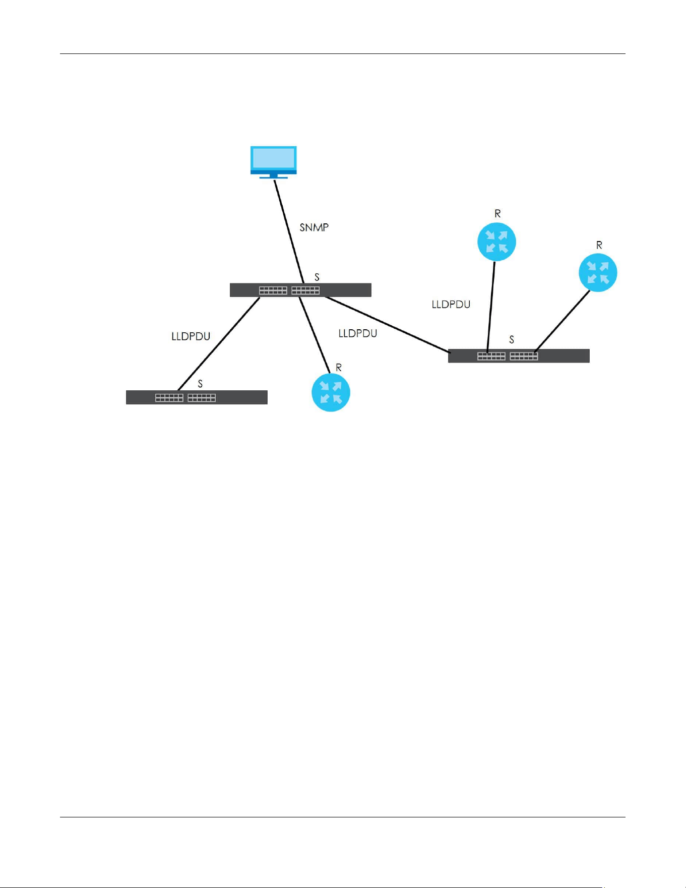
Chapter 36 Link Layer Discovery Protocol (LLDP)
XGS2220 Series User’s Guide
246
The next figure demonstrates that the network devices Switches and Routers (S and R) transmit and
receive device information through LLDPDU and the network manager can query the information using
Simple Network Management Protocol (SNMP).
Figure 178 LLDP Overview
36.2 LLDP-MED Overview
LLDP-MED (Link Layer Discovery Protocol for Media Endpoint Devices) is an extension to the standard
LLDP developed by the Telecommunications Industry Association (TIA) TR-41.4 subcommittee which
defines the enhanced discovery capabilities, such as VoIP applications, to enable network
administrators manage their network topology application more efficiently. Unlike the traditional LLDP,
which has some limitations when handling multiple application devices, the LLDP-MED offers display of
accurate physical topology, interoperability of devices, and easy trouble shooting for mis-configured IP
addresses. There are three classes of endpoint devices that the LLDP-MED supports:
Class I: IP Communications Controllers or other communication related servers
Class II: Voice Gateways, Conference Bridges or Media Servers
Class III: IP-Phones, PC-based Softphones, End user Communication Appliances supporting IP Media
The following figure shows that with the LLDP-MED, network connectivity devices (NCD) like Switches
and Routers will transmit LLDP TLV to endpoint device (ED) like IP Phone first (1), to get its device type
and capabilities information, then it will receive that information in LLDP-MED TLV back from endpoint
devices (2), after that the network connectivity devices will transmit LLDP-MED TLV (3) to provision the
endpoint device to such that the endpoint device’s network policy and location identification
information is updated. Since LLDPDU updates status and configuration information periodically,
network managers may check the result of provision through remote status. The remote status is
updated by receiving LLDP-MED TLVs from endpoint devices.

Chapter 36 Link Layer Discovery Protocol (LLDP)
XGS2220 Series User’s Guide
247
Figure 179 LLDP-MED Overview
36.2.1 What You Can Do – LLDP
• Use the LLDP Local Status screen (Section 36.3 on page 247) to view the Switch’s LLDP information.
• Use the LLDP Remote Status screen (Section 36.4 on page 252) to view LLDP information from the
neighboring devices.
• Use the LLDP Setup screen (Section 36.5 on page 258) to configure LLDP on the Switch.
• Use the Basic TLV Setting screen (Section 36.6 on page 261) to configure basic TLV settings on each
port.
• Use the Org-specific TLV Setting screen (Section 36.7 on page 263) to configure organization-specific
TLV settings on each port.
36.2.2 What You Can Do – LLDP MED
• Use the LLDP-MED Setup screen (Section 36.8 on page 264) to configure LLDP-MED (Link Layer
Discovery Protocol for Media Endpoint Devices) parameters.
• Use the LLDP-MED Network Policy screen (Section 36.9 on page 266) to configure LLDP-MED (Link
Layer Discovery Protocol for Media Endpoint Devices) network policy parameters.
• Use the LLDP-MED Location screen (Section 36.10 on page 268) to configure LLDP-MED (Link Layer
Discovery Protocol for Media Endpoint Devices) location parameters.
36.3 LLDP Local Status
This screen displays a summary of LLDP status on this Switch. Click PORT > LLDP > LLDP > LLDP Local Status
to display the screen as shown next.
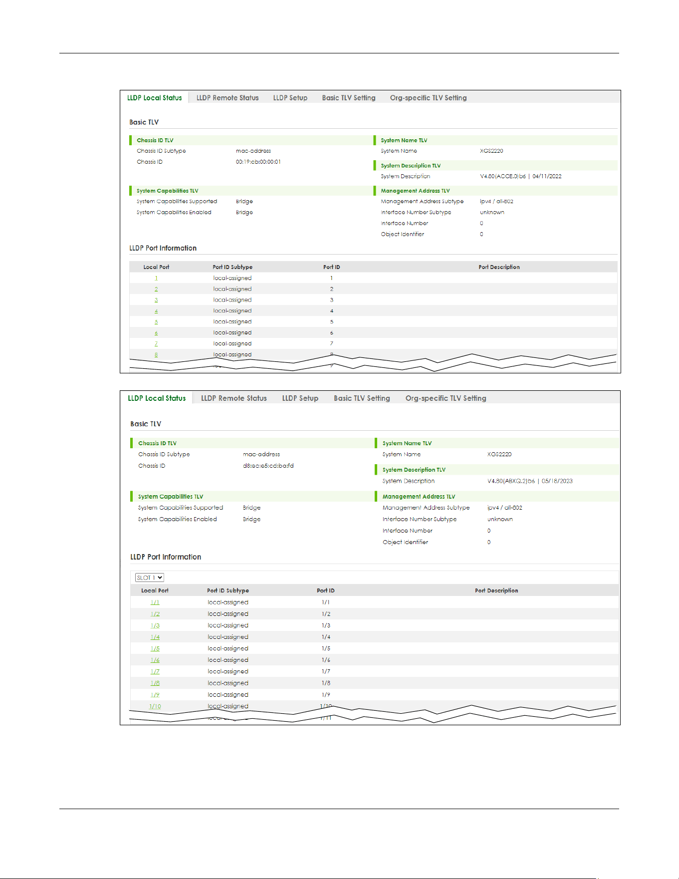
Chapter 36 Link Layer Discovery Protocol (LLDP)
XGS2220 Series User’s Guide
248
Figure 180 PORT > LLDP > LLDP > LLDP Local Status (Standalone Mode)
Figure 181 PORT > LLDP > LLDP > LLDP Local Status (Stacking Mode)
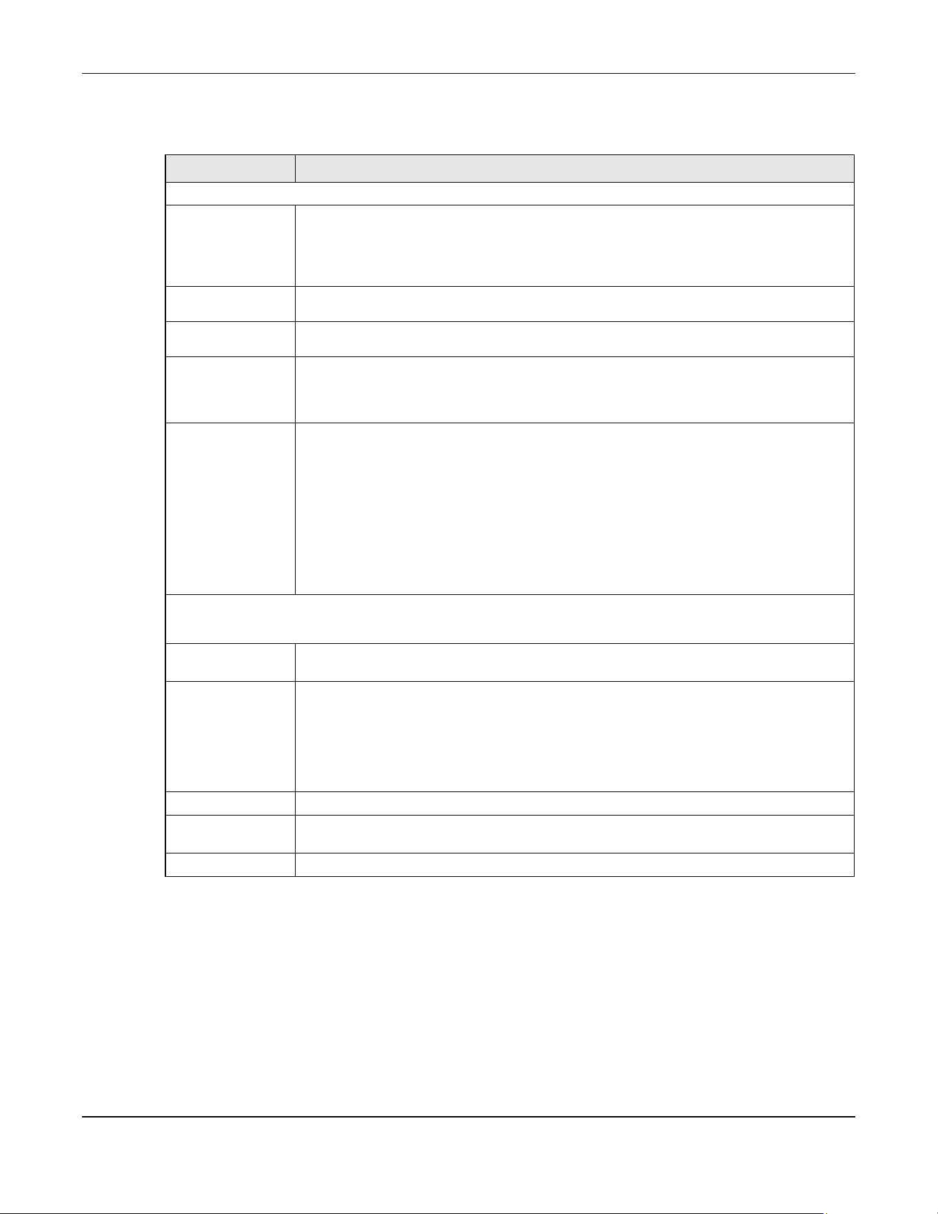
Chapter 36 Link Layer Discovery Protocol (LLDP)
XGS2220 Series User’s Guide
249
The following table describes the labels in this screen.
36.3.1 LLDP Local Port Status Details
This screen displays detailed LLDP status for each port on this Switch. Click PORT > LLDP > LLDP > LLDP
Local Status and then, click a port number, for example 1 in the local port column to display the screen
as shown next.
Table 114 PORT > LLDP > LLDP > LLDP Local Status
LABEL DESCRIPTION
Basic TLV
Chassis ID TLV This displays the chassis ID of the local Switch, that is the Switch you are configuring. The
chassis ID is identified by the chassis ID subtype.
• Chassis ID Subtype – This displays how the chassis of the Switch is identified.
• Chassis ID – This displays the chassis ID of the local Switch.
System Name
TLV
System Name – This shows the host name of the Switch.
System
Description TLV
System Description – This shows the firmware version of the Switch.
System
Capabilities TLV
This shows the System Capabilities enabled and supported on the local Switch.
• System Capabilities Supported – Bridge
• System Capabilities Enabled – Bridge
Management
Address TLV
The Management Address TLV identifies an address associated with the local LLDP agent
that may be used to reach higher layer entities to assist discovery by network management.
The TLV may also include the system interface number and an object identifier (OID) that are
associated with this management address.
This field displays the Management Address settings on the specified ports.
• Management Address Subtype – ipv4 or all-802
• Interface Number Subtype – unknown
• Interface Number – 0 (not supported)
• Object Identifier – 0 (not supported)
LLDP Port Information
This displays the local port information.
SLOT This field appears only in Stacking mode. Click the drop-down list to choose the slot number
of the Switch in a stack.
Local Port This displays the number of the Switch port which receives the LLDPDU from the remote
device. Click a port number to view the detailed LLDP status on this port at LLDP Local Port
Status Detail screen.
In Stacking mode, the first number represents the slot ID and the second is the port number.
Please note that the default stacking ports (the last four ports of your Switch) cannot be
configured. They are reserved for stacking only.
Port ID Subtype This indicates how the port ID field is identified.
Port ID This is an alpha-numeric string that contains the specific identifier for the port from which this
LLDPDU was transmitted.
Port Description This shows the port description that the Switch will advertise from this port.
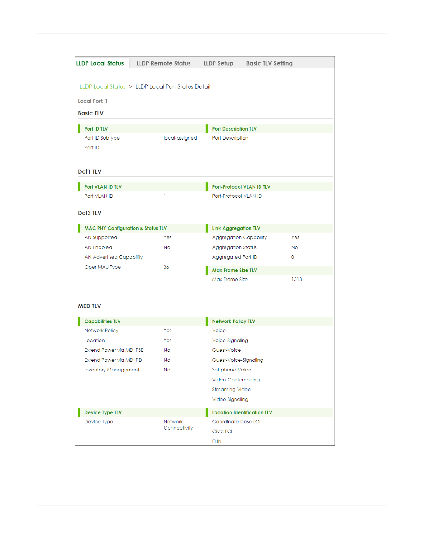
Chapter 36 Link Layer Discovery Protocol (LLDP)
XGS2220 Series User’s Guide
250
Figure 182 PORT > LLDP > LLDP > LLDP Local Status > LLDP Local Port Status Detail
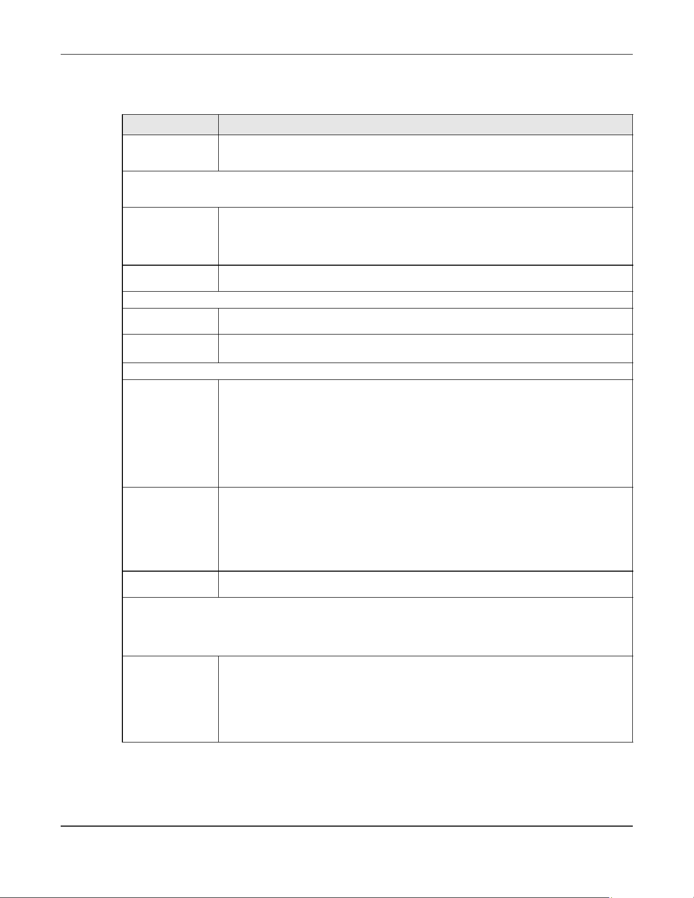
Chapter 36 Link Layer Discovery Protocol (LLDP)
XGS2220 Series User’s Guide
251
The following table describes the labels in this screen.
Table 115 PORT > LLDP > LLDP > LLDP Local Status > LLDP Local Port Status Details
LABEL DESCRIPTION
Local Port This displays the number of the Switch’s port.
In Stacking mode, the first number represents the slot ID and the second is the port number.
Basic TLV
These are the Basic TLV flags
Port ID TLV The port ID TLV identifies the specific port that transmitted the LLDP frame.
• Port ID Subtype – This shows how the port is identified.
• Port ID – This is the ID of the port. In stacking mode, the first number represents the slot and
the second the port number.
Port Description
TLV
Port Description – This displays the local port description.
Dot1 TLV
Port VLAN ID
TLV
Port VLAN ID – This displays the VLAN ID sent by the IEEE 802.1 Port VLAN ID TLV.
Port-Protocol
VLAN ID TLV
Port-Protocol VLAN ID – This displays the IEEE 802.1 Port Protocol VLAN ID TLVs, which indicates
whether the VLAN is enabled and supported.
Dot3 TLV
MAC PHY
Configuration &
Status TLV
The MAC/PHY Configuration/Status TLV advertises the bit-rate and duplex capability of the
sending 802.3 node. It also advertises the current duplex and bit-rating of the sending node.
Lastly, it advertises whether these setting were the result of auto-negotiation during link
initiation or manual override.
• AN Supported – Displays if the port supports or does not support auto-negotiation.
• AN Enabled – The current auto-negotiation status of the port.
• AN Advertised Capability – The auto-negotiation capabilities of the port.
• Oper MAU Type – The current Medium Attachment Unit (MAU) type of the port.
Link
Aggregation
TLV
The Link Aggregation TLV indicates whether the link is capable of being aggregated,
whether the link is currently in an aggregation, and if in an aggregation, the port
identification of the aggregation.
• Aggregation Capability – The current aggregation capability of the port.
• Aggregation Status – The current aggregation status of the port.
• Aggregation Port ID – The aggregation ID of the current port.
Max Frame Size
TLV
This displays the maximum supported frame size in octets.
MED TLV
LLDP Media Endpoint Discovery (MED) is an extension of LLDP that provides additional capabilities to support
media endpoint devices. MED enables advertisement and discovery of network policies, device location discovery
to allow creation of location databases, and information for troubleshooting.
Capabilities TLV This field displays which LLDP-MED TLV are capable to transmit on the Switch.
• Network Policy
• Location
• Extend Power via MDI PSE
• Extend Power via MDI PD
• Inventory Management

Chapter 36 Link Layer Discovery Protocol (LLDP)
XGS2220 Series User’s Guide
252
36.4 LLDP Remote Status
This screen displays a summary of LLDP status for each LLDP connection to a neighboring Switch. Click
PORT > LLDP > LLDP > LLDP Remote Status to display the screen as shown next.
Figure 183 PORT > LLDP > LLDP > LLDP Remote Status (Standalone Mode)
Figure 184 PORT > LLDP > LLDP > LLDP Remote Status (Stacking Mode)
Network Policy
TLV
This displays a network policy for the specified application.
•Voice
• Voice-Signaling
•Guest-Voice
• Guest-Voice-Signaling
• Softphone-Voice
• Video-Conferencing
•Streaming-Video
• Video-Signaling
Device Type
TLV
Device Type – This is the LLDP-MED device class.
The Zyxel Switch device type is:
• Network Connectivity
Location
Identification
TLV
This shows the location information of a caller by its ELIN (Emergency Location Identifier
Number) or the IETF Geopriv Civic Address based Location Configuration Information (Civic
Address LCI).
• Coordinate-based LCI – Latitude, longitude and altitude coordinates of the location
Configuration Information (LCI)
• Civic LCI – IETF Geopriv Civic Address based Location Configuration Information
• ELIN – (Emergency Location Identifier Number)
Table 115 PORT > LLDP > LLDP > LLDP Local Status > LLDP Local Port Status Details (continued)
LABEL DESCRIPTION

Chapter 36 Link Layer Discovery Protocol (LLDP)
XGS2220 Series User’s Guide
253
The following table describes the labels in this screen.
36.4.1 LLDP Remote Port Status Details
This screen displays detailed LLDP status of the remote device connected to the Switch. Click PORT >
LLDP > LLDP > LLDP Remote Status and then click an index number, for example 1, in the Index column in
the LLDP Remote Status screen to display the screen as shown next.
Figure 185 PORT > LLDP > LLDP > LLDP Remote Status > LLDP Remote Port Status Details (Basic TLV)
Table 116 PORT > LLDP > LLDP > LLDP Remote Status
LABEL DESCRIPTION
SLOT This field appears only in Stacking mode. Click the drop-down list to choose the slot number
of the Switch in a stack.
Index The index number shows the number of remote devices that are connected to the Switch.
Click on an index number to view the detailed LLDP status for this remote device in the LLDP
Remote Port Status Details screen.
Local Port This is the number of the Switch’s port that received LLDPDU from the remote device. In
stacking mode, the first number represents the slot and the second the port number.
Chassis ID This displays the chassis ID of the remote device associated with the transmitting LLDP agent.
The chassis ID is identified by the chassis ID subtype. For example, the MAC address of the
remote device.
Port ID This is an alpha-numeric string that contains the specific identifier for the port from which this
LLDPDU was transmitted. The port ID is identified by the port ID subtype.
Port Description This displays a description for the port from which this LLDPDU was transmitted.
System Name This displays the system name of the remote device.
Management
Address
This displays the management address of the remote device. It could be the MAC address or
IP address.
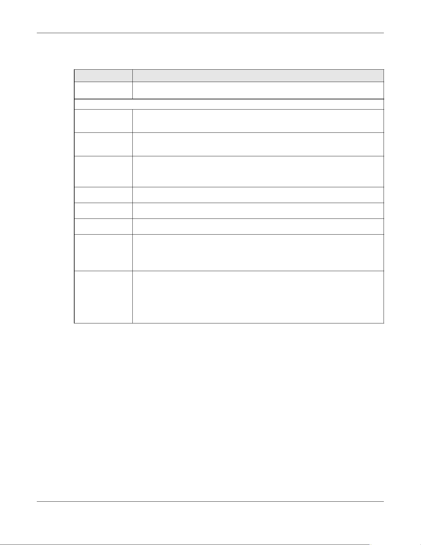
Chapter 36 Link Layer Discovery Protocol (LLDP)
XGS2220 Series User’s Guide
254
The following table describes the labels in Basic TLV part of the screen.
Table 117 PORT > LLDP > LLDP > LLDP Remote Status > LLDP Remote Port Status Details (Basic TLV)
LABEL DESCRIPTION
Local Port This displays the number of the Switch’s port to which the remote device is connected. In
Stacking mode, the first number represents the slot and the second the port number.
Basic TLV
Chassis ID TLV • Chassis ID Subtype – This displays how the chassis of the remote device is identified.
• Chassis ID – This displays the chassis ID of the remote device. The chassis ID is identified by
the chassis ID subtype.
Port ID TLV • Port ID Subtype – This displays how the port of the remote device is identified.
• Port ID – This displays the port ID of the remote device. The port ID is identified by the port
ID subtype.
Time To Live TLV Time To Live – This displays the time-to-live (TTL) multiplier of LLDP frames. The device
information on the neighboring devices ages out and is discarded when its corresponding
TTL expires. The TTL value is to multiply the TTL multiplier by the LLDP frames transmitting
interval.
Port Description
TLV
Port Description – This displays the remote port description.
System Name
TLV
System Name – This displays the system name of the remote device.
System
Description TLV
System Description – This displays the system description of the remote device.
System
Capabilities TLV
This displays whether the system capabilities are enabled and supported on the remote
device.
• System Capabilities Supported
• System Capabilities Enabled
Management
Address TLV
This displays the management address (IPv4 and IPv6) of the remote device.
• Management Address Subtype
• Management Address
• Interface Number Subtype
• Interface Number
• Object Identifier

Chapter 36 Link Layer Discovery Protocol (LLDP)
XGS2220 Series User’s Guide
255
Figure 186 PORT > LLDP > LLDP > LLDP Remote Status > LLDP Remote Port Status Details (Dot1 and Dot3
TLV)
The following table describes the labels in the Dot1 and Dot3 parts of the screen.
Table 118 PORT > LLDP > LLDP > LLDP Remote Status > LLDP Remote Port Status Details (Dot1 and Dot3
TLV)
LABEL DESCRIPTION
Dot1 TLV
Port VLAN ID
TLV
Port VLAN ID – This displays the VLAN ID of this port on the remote device.
Vlan Name TLV This shows the VLAN ID and name for remote device port.
•VLAN ID
• VLAN Name
Protocol
Identity TLV
Protocol ID – The Protocol Identity TLV allows the Switch to advertise the particular protocols
that are accessible through its port.
Port-Protocol
VLAN ID TLV
This displays the IEEE 802.1 Port Protocol VLAN ID TLV, which indicates whether the VLAN ID
and whether it is enabled and supported on the port of remote Switch which sent the
LLDPDU.
• Port-Protocol VLAN ID
• Port-Protocol VLAN ID Supported
• Port-Protocol VLAN ID Enabled
Dot3 TLV

Chapter 36 Link Layer Discovery Protocol (LLDP)
XGS2220 Series User’s Guide
256
MAC PHY
Configuration &
Status TLV
The MAC/PHY Configuration/Status TLV advertises the bit-rate and duplex capability of the
sending 802.3 node. It also advertises the current duplex and bit-rating of the sending node.
Lastly, it advertises whether these setting were the result of auto-negotiation during link
initiation or manual override.
• AN Supported – Displays if the port supports or does not support auto-negotiation.
• AN Enabled – The current auto-negotiation status of the port.
• AN Advertised Capability – The auto-negotiation capabilities of the port.
• Oper MAU Type – The current Medium Attachment Unit (MAU) type of the port.
Max Frame Size
TLV
Max Frame Size – This displays the maximum supported frame size in octets.
Link
Aggregation
TLV
The Link Aggregation TLV indicates whether the link is capable of being aggregated,
whether the link is currently in an aggregation, and if in an aggregation, the port
identification of the aggregation.
• Aggregation Capability – The current aggregation capability of the port.
• Aggregation Status – The current aggregation status of the port.
• Aggregated Port ID – The aggregation ID of the current port.
Power Via MDI
TLV
The Power Via MDI TLV allows network management to advertise and discover the MDI
power support capabilities of the sending port on the remote device.
•Port Class
• MDI Supported
• MDI Enabled
• Pair Controllable
• PSE Power Pairs
•Power Class
Table 118 PORT > LLDP > LLDP > LLDP Remote Status > LLDP Remote Port Status Details (Dot1 and Dot3
TLV) (continued)
LABEL DESCRIPTION
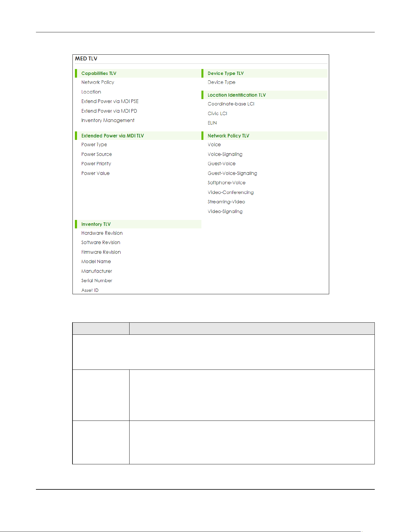
Chapter 36 Link Layer Discovery Protocol (LLDP)
XGS2220 Series User’s Guide
257
Figure 187 PORT > LLDP > LLDP > LLDP Remote Status > LLDP Remote Port Status Details (MED TLV)
The following table describes the labels in the MED TLV part of the screen.
Table 119 PORT > LLDP > LLDP > LLDP Remote Status > LLDP Remote Port Status Details (MED TLV)
LABEL DESCRIPTION
MED TLV
LLDP Media Endpoint Discovery (MED) is an extension of LLDP that provides additional capabilities to support
media endpoint devices. MED enables advertisement and discovery of network policies, device location discovery
to allow creation of location databases, and information for troubleshooting.
Capabilities TLV This displays the MED capabilities the remote port supports.
• Network Policy
• Location
• Extend Power via MDI PSE
• Extend Power via MDI PD
• Inventory Management
Device Type
TLV
LLDP-MED endpoint device classes:
• Endpoint Class I
• Endpoint Class II
• Endpoint Class III
• Network Connectivity

Chapter 36 Link Layer Discovery Protocol (LLDP)
XGS2220 Series User’s Guide
258
36.5 LLDP Setup
Use this screen to configure global LLDP settings on the Switch. Click PORT > LLDP > LLDP > LLDP Setup to
display the screen as shown next.
Location
Identification
TLV
This shows the location information of a caller by its:
• Coordinate-base LCI – Latitude and longitude coordinates of the Location Configuration
Information (LCI)
• Civic LCI – IETF Geopriv Civic Address based Location Configuration Information
• ELIN – (Emergency Location Identifier Number)
Extended
Power via MDI
TLV
Extended Power Via MDI Discovery enables detailed power information to be advertised by
Media Endpoints, such as IP phones and Network Connectivity Devices such as the Switch.
• Power Type – Whether it is currently operating from primary power or is on backup power
(backup power may indicate to the Endpoint Device that it should move to a power
conservation mode).
• Power Source – Whether or not the Endpoint is currently operating from an external
power source.
• Power Priority – The Endpoint Device’s power priority (which the Network Connectivity
Device may use to prioritize which devices will remain in service during power shortages).
• Power Value – Power requirement, in fractions of Watts, in current configuration.
Network Policy
TLV
This displays a network policy for the specified application.
•Voice
• Voice-Signaling
•Guest-Voice
• Guest-Voice-Signaling
• Softphone-Voice
• Video-Conferencing
•Streaming-Video
• Video-Signaling
Inventory TLV The majority of IP Phones lack support of management protocols such as SNMP, so LLDP-MED
inventory TLVs are used to provide their inventory information to the Network Connectivity
Devices such as the Switch. The Inventory TLV may contain the following information.
• Hardware Revision
• Software Revision
•Firmware Revision
• Model Name
• Manufacturer
• Serial Number
•Asset ID
Table 119 PORT > LLDP > LLDP > LLDP Remote Status > LLDP Remote Port Status Details (MED TLV)
LABEL DESCRIPTION
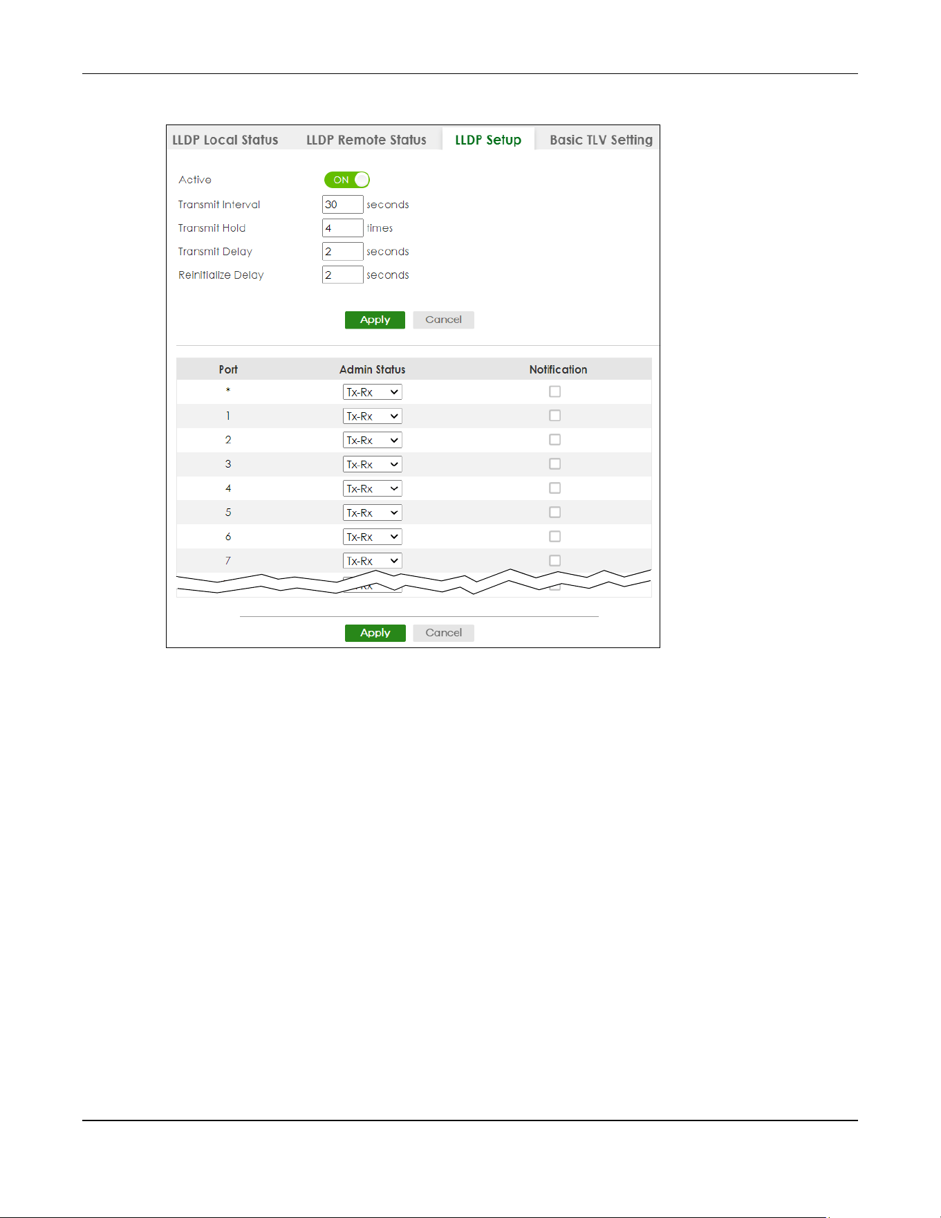
Chapter 36 Link Layer Discovery Protocol (LLDP)
XGS2220 Series User’s Guide
259
Figure 188 PORT > LLDP > LLDP > LLDP Setup (Standalone Mode)
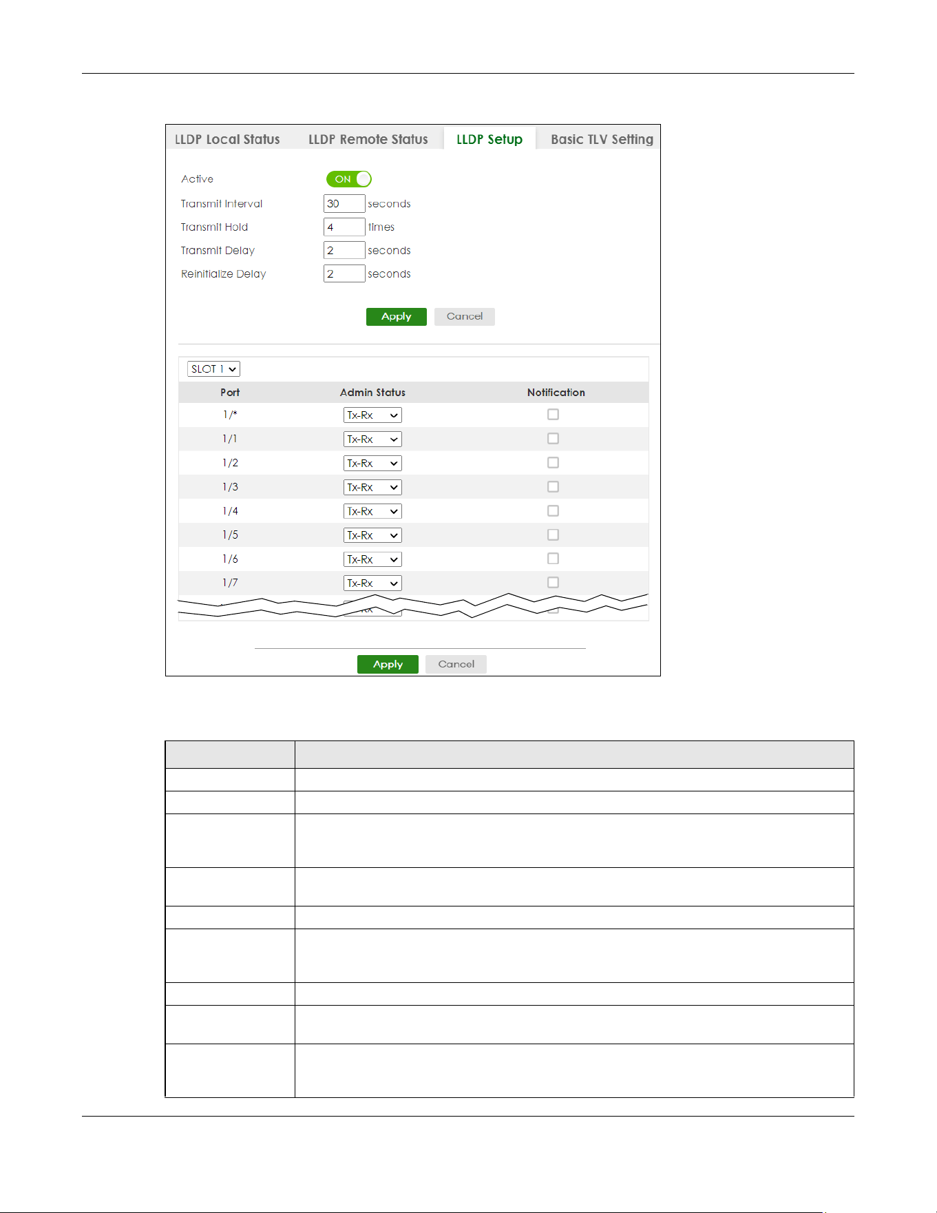
Chapter 36 Link Layer Discovery Protocol (LLDP)
XGS2220 Series User’s Guide
260
Figure 189 PORT > LLDP > LLDP > LLDP Setup (Stacking Mode)
The following table describes the labels in this screen.
Table 120 PORT > LLDP > LLDP > LLDP Setup
LABEL DESCRIPTION
Active Select to enable LLDP on the Switch. It is enabled by default.
Transmit Interval Enter how many seconds the Switch waits before sending LLDP packets.
Transmit Hold Enter the time-to-live (TTL) multiplier of LLDP frames. The device information on the
neighboring devices ages out and is discarded when its corresponding TTL expires. The TTL
value is to multiply the TTL multiplier by the LLDP packets transmitting interval.
Transmit Delay Enter the delay (in seconds) between successive LLDPDU transmissions initiated by value or
status changes in the Switch MIB.
Reinitialize Delay Enter the number of seconds for LLDP to wait before initializing on a port.
Apply Click Apply to save your changes to the Switch’s run-time memory. The Switch loses these
changes if it is turned off or loses power, so use the Save link on the top navigation panel to
save your changes to the non-volatile memory when you are done configuring.
Cancel Click Cancel to begin configuring this screen afresh.
SLOT This field appears only in Stacking mode. Click the drop-down list to choose the slot number
of the Switch in a stack.
Port This field displays the port number. In Stacking mode, the first number represents the slot ID
and the second is the port number. Please note that the default stacking ports (the last four
ports of your Switch) cannot be configured. They are reserved for stacking only.
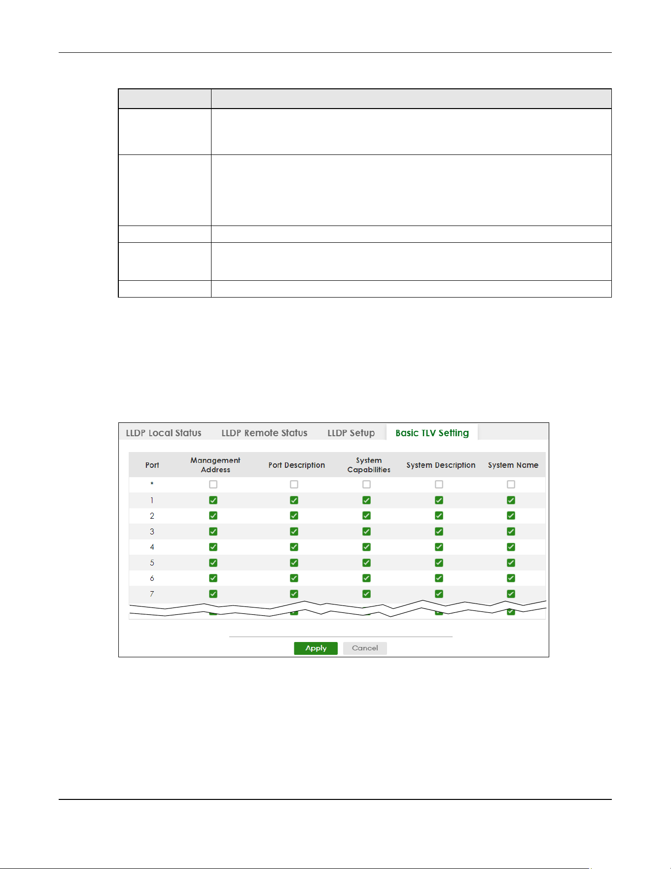
Chapter 36 Link Layer Discovery Protocol (LLDP)
XGS2220 Series User’s Guide
261
36.6 Basic TLV Setting
Use this screen to configure Basic TLV settings. Click PORT > LLDP > LLDP > Basic TLV Setting to display the
screen as shown next.
Figure 190 PORT > LLDP > LLDP > Basic TLV Setting (Standalone Mode)
* Use this row to make the setting the same for all ports. Use this row first and then make
adjustments to each port if necessary.
Changes in this row are copied to all the ports as soon as you make them.
Admin Status Select whether LLDP transmission and/or reception is allowed on this port.
• Disable – not allowed
• Tx-Only – transmit only
• Rx-Only – receive only
• Tx-Rx – transmit and receive
Notification Select whether LLDP notification is enabled on this port.
Apply Click Apply to save your changes to the Switch’s run-time memory. The Switch loses these
changes if it is turned off or loses power, so use the Save link on the top navigation panel to
save your changes to the non-volatile memory when you are done configuring.
Cancel Click Cancel to begin configuring this screen afresh.
Table 120 PORT > LLDP > LLDP > LLDP Setup (continued)
LABEL DESCRIPTION
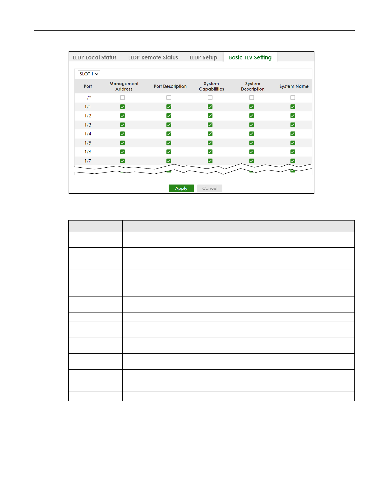
Chapter 36 Link Layer Discovery Protocol (LLDP)
XGS2220 Series User’s Guide
262
Figure 191 PORT > LLDP > LLDP > Basic TLV Setting (Stacking Mode)
The following table describes the labels in this screen.
Table 121 PORT > LLDP > LLDP > Basic TLV Setting
LABEL DESCRIPTION
SLOT This field appears only in Stacking mode. Click the drop-down list to choose the slot number
of the Switch in a stack.
Port This field displays the port number. In Stacking mode, the first number represents the slot ID
and the second is the port number. Please note that the default stacking ports (the last four
ports of your Switch) cannot be configured. They are reserved for stacking only.
* Use this row to make the setting the same for all ports. Use this row first and then make
adjustments to each port if necessary.
Changes in this row are copied to all the ports as soon as you make them.
Management
Address
Select the check boxes to enable or disable the sending of Management Address TLVs on
the ports.
Port Description Select the check boxes to enable or disable the sending of Port Description TLVs on the ports.
System Capabilities Select the check boxes to enable or to disable the sending of System Capabilities TLVs on the
ports.
System Description Select the check boxes to enable or to disable the sending of System Description TLVs on the
ports.
System Name Select the check boxes to enable or to disable the sending of System Name TLVs on the
ports.
Apply Click Apply to save your changes to the Switch’s run-time memory. The Switch loses these
changes if it is turned off or loses power, so use the Save link on the top navigation panel to
save your changes to the non-volatile memory when you are done configuring.
Cancel Click Cancel to begin configuring this screen afresh.
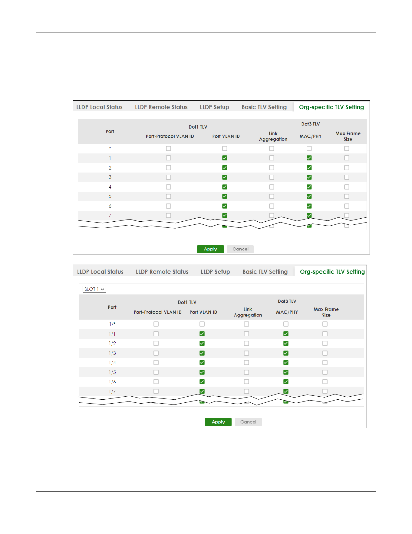
Chapter 36 Link Layer Discovery Protocol (LLDP)
XGS2220 Series User’s Guide
263
36.7 Org-specific TLV Setting
Use this screen to configure organization-specific TLV settings. Click PORT > LLDP > LLDP > Org-specific
TLV Setting to display the screen as shown next.
Figure 192 PORT > LLDP > LLDP > Org-specific TLV Setting (Standalone Mode)
Figure 193 PORT > LLDP > LLDP > Org-specific TLV Setting (Stacking Mode)

Chapter 36 Link Layer Discovery Protocol (LLDP)
XGS2220 Series User’s Guide
264
The following table describes the labels in this screen.
36.8 LLDP-MED Setup
Click PORT > LLDP > LLDP MED > LLDP-MED Setup to display the screen as shown next.
Table 122 PORT > LLDP > LLDP > Org-specific TLV Setting
LABEL DESCRIPTION
SLOT This field appears only in Stacking mode. Click the drop-down list to choose the slot number
of the Switch in a stack.
Port This field displays the port number. In Stacking mode, the first number represents the slot ID
and the second is the port number. Please note that the default stacking ports (the last four
ports of your Switch) cannot be configured. They are reserved for stacking only.
* Use this row to make the setting the same for all ports. Use this row first and then make
adjustments to each port if necessary.
Changes in this row are copied to all the ports as soon as you make them.
Dot1 TLV
Port-Protocol
VLAN ID
Select the check boxes to enable or disable the sending of IEEE 802.1 Port and Protocol VLAN
ID TLVs on the ports.
Port VLAN ID Select the check boxes to enable or disable the sending of IEEE 802.1 Port VLAN ID TLVs on
the ports. All check boxes in this column are enabled by default.
Dot3 TLV
Link
Aggregation
Select the check boxes to enable or disable the sending of IEEE 802.3 Link Aggregation TLVs
on the ports.
MAC/PHY Select the check boxes to enable or disable the sending of IEEE 802.3 MAC/PHY
Configuration/Status TLVs on the ports. All check boxes in this column are enabled by default.
Max Frame Size Select the check boxes to enable or disable the sending of IEEE 802.3 Max Frame Size TLVs on
the ports.
Apply Click Apply to save your changes to the Switch’s run-time memory. The Switch loses these
changes if it is turned off or loses power, so use the Save link on the top navigation panel to
save your changes to the non-volatile memory when you are done configuring.
Cancel Click Cancel to begin configuring this screen afresh.
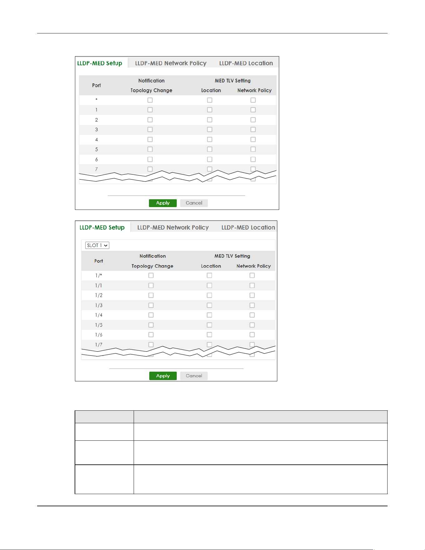
Chapter 36 Link Layer Discovery Protocol (LLDP)
XGS2220 Series User’s Guide
265
Figure 194 PORT > LLDP > LLDP MED > LLDP-MED Setup (Standalone Mode)
Figure 195 PORT > LLDP > LLDP MED > LLDP-MED Setup (Stacking Mode)
The following table describes the labels in this screen.
Table 123 PORT > LLDP > LLDP MED> LLDP-MED Setup
LABEL DESCRIPTION
SLOT This field appears only in Stacking mode. Click the drop-down list to choose the slot number
of the Switch in a stack.
Port This field displays the port number. In stacking mode, the first number represents the slot ID
and the second is the port number. Please note that the default stacking ports (the last four
ports of your Switch) cannot be configured. They are reserved for stacking only.
* Use this row to make the setting the same for all ports. Use this row first and then make
adjustments to each port if necessary.
Changes in this row are copied to all the ports as soon as you make them.

Chapter 36 Link Layer Discovery Protocol (LLDP)
XGS2220 Series User’s Guide
266
36.9 LLDP-MED Network Policy
Click PORT > LLDP > LLDP MED > LLDP-MED Network Policy to display the screen as shown next.
Figure 196 PORT > LLDP > LLDP MED > LLDP-MED Network Policy
The following table describes the labels in this screen.
Notification
Topology
Change
Select to enable LLDP-MED topology change traps on this port.
MED TLV Setting
Location Select to enable transmitting LLDP-MED location TLV.
Network Policy Select to enable transmitting LLDP-MED Network Policy TLV.
Apply Click Apply to save the changes to the Switch’s run-time memory. The Switch loses these
changes if it is turned off or loses power, so use the Save link on the top navigation panel to
save your changes to the non-volatile memory when you are done configuring.
Cancel Click Cancel to begin configuring this screen afresh.
Table 123 PORT > LLDP > LLDP MED> LLDP-MED Setup (continued)
LABEL DESCRIPTION
Table 124 PORT > LLDP > LLDP MED > LLDP-MED Network Policy
LABEL DESCRIPTION
Index This field displays the of index number of the network policy. Click an index number to edit
the rule.
Port This field displays the port number of the network policy. In Stacking mode, the first number
represents the slot and the second the port number.
Application Type This field displays the application type of the network policy.
Tag This field displays the Tag Status of the network policy.
VLAN This field displays the VLAN ID of the network policy.
DSCP This field displays the DSCP value of the network policy.
Priority This field displays the priority value of the network policy.
Select an entry’s check box to select a specific entry. Otherwise, select the check box in the
table heading row to select all entries.
Add/Edit Click Add/Edit to add a new schedule rule or edit a selected one.
Delete Select the rules that you want to remove, then click Delete.
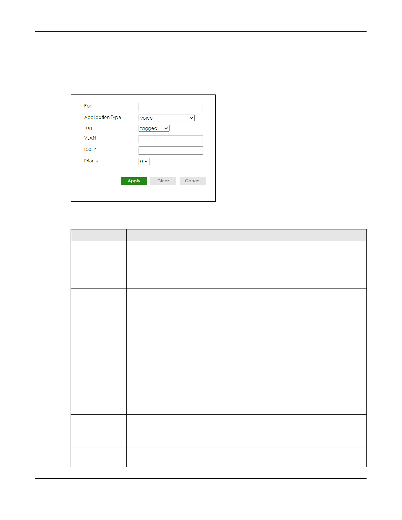
Chapter 36 Link Layer Discovery Protocol (LLDP)
XGS2220 Series User’s Guide
267
36.9.1 Add/Edit LLDP-MED Network Policy
To access this screen, click the Add/Edit button or select an entry from the list and click the Add/Edit
button.
Figure 197 PORT > LLDP > LLDP MED > LLDP-MED Network Policy > Add/Edit
The following table describes the labels in this screen.
Table 125 PORT > LLDP > LLDP MED > LLDP-MED Network Policy > Add/Edit
LABEL DESCRIPTION
Port Enter the port number to set up the LLDP-MED network policy. You can enter multiple ports
separated by (no space) comma (“,”) or hyphen (“-”) for a range. For example, enter “3-5”
for ports 3, 4, and 5. Enter “3,5,7” for ports 3, 5, and 7.
In Stacking mode, the first number represents the slot and the second the port number. Enter
“1/1-1/24,2/23” for ports 1 to 24 for the Switch in slot 1 and port 23 for the Switch in slot 2, for
example.
Application Type Select the type of application used in the network policy.
• voice
• voice-signaling
•guest-voice
• guest-voice-signaling
• softphone-voice
• video-conferencing
• streaming-video
• video-signaling
Tag Select to tag or untag in the network policy.
•tagged
• untagged
VLAN Enter the VLAN ID number. It should be from 1 to 4094. For priority tagged frames, enter “0”.
DSCP Enter the DSCP value of the network policy. The value is defined from 0 through 63 with the 0
representing use of the default DSCP value.
Priority Enter the priority value for the network policy.
Apply Click Apply to save your changes to the Switch’s run-time memory. The Switch loses these
changes if it is turned off or loses power, so use the Save link on the top navigation panel to
save your changes to the non-volatile memory when you are done configuring.
Clear Click Clear to clear the fields to the factory defaults.
Cancel Click Cancel to not save the configuration you make and return to the last screen.
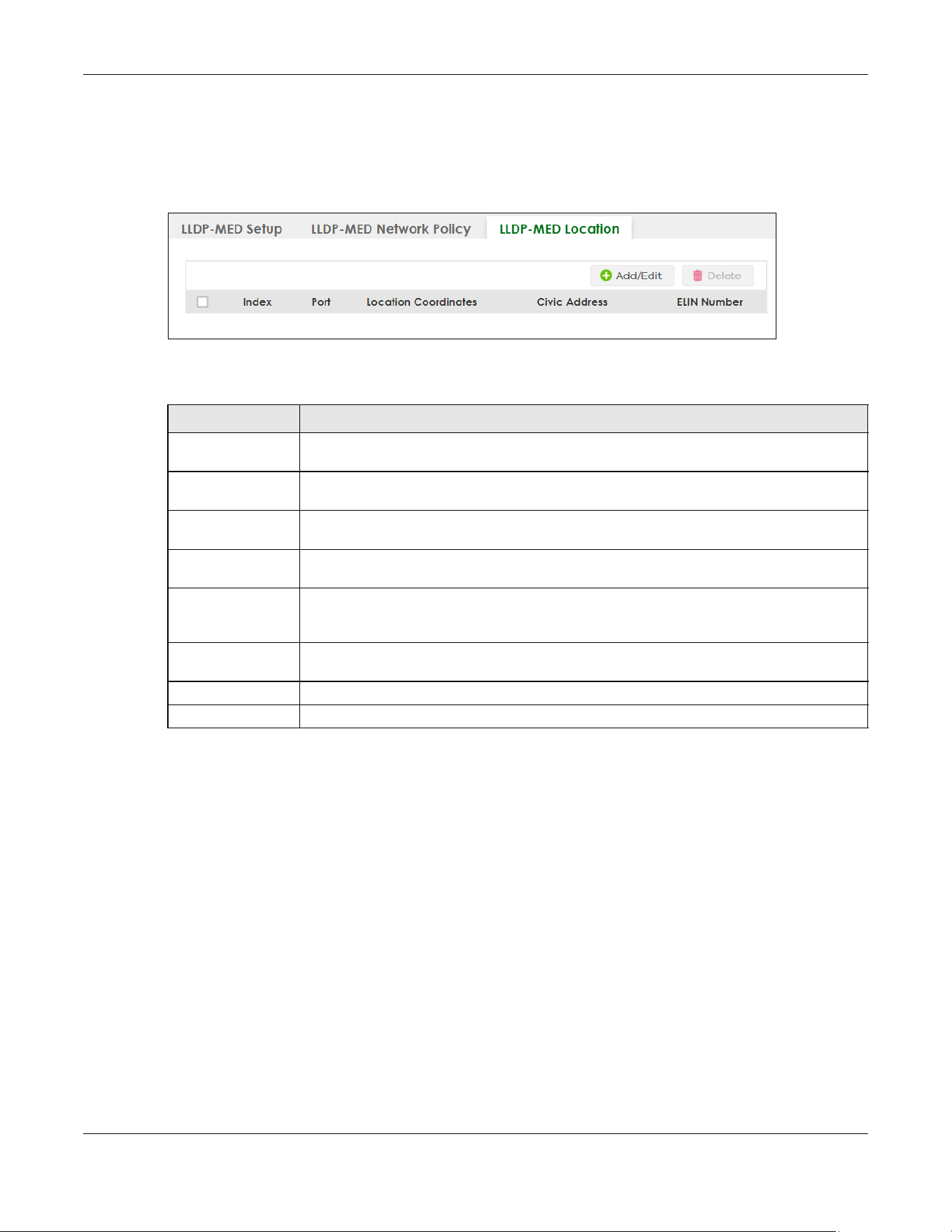
Chapter 36 Link Layer Discovery Protocol (LLDP)
XGS2220 Series User’s Guide
268
36.10 LLDP-MED Location
Click PORT > LLDP > LLDP MED > LLDP-MED Location to display the screen as shown next.
Figure 198 PORT > LLDP > LLDP MED > LLDP-MED Location
The following table describes the labels in this screen.
36.10.1 Add/Edit LLDP-MED Location
To access this screen, click the Add/Edit button or select an entry from the list and click the Add/Edit
button.
Table 126 PORT > LLDP > LLDP MED > LLDP-MED Location
LABEL DESCRIPTION
Index This lists the index number of the location configuration. Click an index number to view or edit
the location.
Port This lists the port number of the location configuration. In Stacking mode, the first number
represents the slot and the second the port number.
Location
Coordinates
This field displays the location configuration information based on geographical coordinates
that includes longitude, latitude, altitude and datum.
Civic Address This field displays the Civic Address for the remote device using information such as Country,
State, County, City, Street, Number, ZIP code and additional information.
ELIN Number This field shows the Emergency Location Identification Number (ELIN), which is used to
identify endpoint devices when they issue emergency call services. The valid length is form
10 to 25 characters.
Select an entry’s check box to select a specific entry. Otherwise, select the check box in the
table heading row to select all entries.
Add/Edit Click Add/Edit to add a new location or edit a selected one.
Delete Select the locations that you want to remove, then click Delete.

Chapter 36 Link Layer Discovery Protocol (LLDP)
XGS2220 Series User’s Guide
269
Figure 199 PORT > LLDP > LLDP MED > LLDP-MED Location > Add/Edit (Standalone Mode)

Chapter 36 Link Layer Discovery Protocol (LLDP)
XGS2220 Series User’s Guide
270
Figure 200 PORT > LLDP > LLDP MED > LLDP-MED Location > Add/Edit (Stacking Mode)
The following table describes the labels in this screen.
Table 127 PORT > LLDP > LLDP MED > LLDP-MED Location > Add/Edit
LABEL DESCRIPTION
Port Enter the port number you want to set up the location within the LLDP-MED network. In
Stacking mode, the first field is the slot ID and the second field is the port number.
Location Coordinates
The LLDP-MED uses geographical coordinates and Civic Address to set the location information of the remote
device. Geographical based coordinates includes latitude, longitude, altitude and datum. Civic Address includes
Country, State, County, City, Street and other related information.
Latitude Enter the latitude information. The value should be from 0º to 90º.
•north
•south

Chapter 36 Link Layer Discovery Protocol (LLDP)
XGS2220 Series User’s Guide
271
Longitude Enter the longitude information. The value should be from 0º to 180º.
•west
•east
Altitude Enter the altitude information. The value should be from –2097151 to 2097151 in meters or in
floors.
•meters
•floor
Datum Select the appropriate geodetic datum used by GPS.
•WGS84
• NAD83-NAVD88
• NAD83-MLLW
Civic Address Enter the Civic Address by providing information such as Country, State, County, City, Street,
Number, ZIP code and other additional information. Enter at least 2 fields in this configuration
including the Country. The valid length of the Country field is 2 characters and all other fields
are up to 32 characters.
• Country
• State
• County
• City
• Division
• Neighbor
• Street
• Leading-Street-Direction
• Street-Suffix
• Trailing-Street-Suffix
•House-Number
• House-Number-Suffix
• Landmark
• Additional-Location
•Name
•Zip-Code
• Building
•Unit
• Floor
• Room-Number
• Place-Type
• Postal-Community-Name
• Post-Office-Box
• Additional-Code
ELIN Number Enter a numerical digit string, corresponding to the ELIN identifier which is used during
emergency call setup to a traditional CAMA or ISDN trunk-based PSAP. The valid length is
from 10 to 25 characters.
Apply Click Apply to save your changes to the Switch’s run-time memory. The Switch loses these
changes if it is turned off or loses power, so use the Save link on the top navigation panel to
save your changes to the non-volatile memory when you are done configuring.
Clear Click Clear to clear the fields to the factory defaults.
Cancel Click Cancel to not save the configuration you make and return to the last screen.
Table 127 PORT > LLDP > LLDP MED > LLDP-MED Location > Add/Edit (continued)
LABEL DESCRIPTION

Chapter 37 OAM
XGS2220 Series User’s Guide
272
CHAPTER 37
OAM
37.1 OAM Overview
Link layer Ethernet OAM (Operations, Administration and Maintenance) as described in IEEE 802.3ah is a
link monitoring protocol. It utilizes OAM Protocol Data Units or OAM PDUs to transmit link status
information between directly connected Ethernet devices. Both devices must support IEEE 802.3ah.
Because link layer Ethernet OAM operates at layer two of the OSI (Open Systems Interconnection Basic
Reference) model, neither IP or SNMP are necessary to monitor or troubleshoot network connection
problems.
The Switch supports the following IEEE 802.3ah features:
• Discovery – this identifies the devices on each end of the Ethernet link and their OAM configuration.
• Remote Loopback – this can initiate a loopback test between Ethernet devices.
37.1.1 What You Can Do
• Use the OAM Status screen (Section 37.2 on page 272) to view the configuration of ports on which
Ethernet OAM is enabled.
• Use the OAM Setup screen (Section 37.3 on page 278) to enable Ethernet OAM on the Switch.
• Use the OAM Remote Loopback screen (Section 37.4 on page 280) to perform remote-loopback tests.
37.2 OAM Status
Use this screen to view the configuration of ports on which Ethernet OAM is enabled. Click PORT > OAM
> OAM Status in the navigation panel.
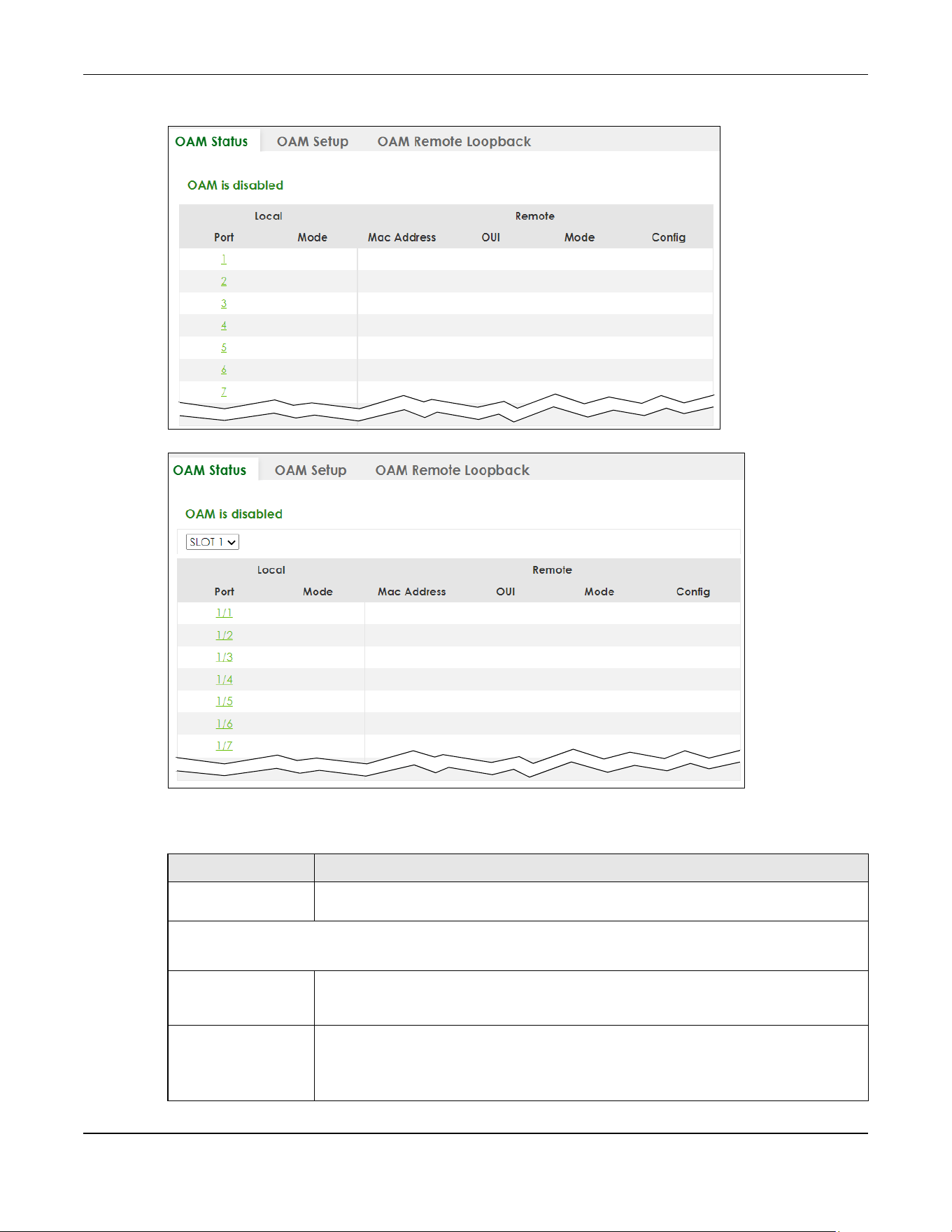
Chapter 37 OAM
XGS2220 Series User’s Guide
273
Figure 201 PORT > OAM > OAM Status (Standalone Mode)
Figure 202 PORT > OAM > OAM Status (Stacking Mode)
The following table describes the fields in the above screen.
Table 128 PORT > OAM > OAM Status
LABEL DESCRIPTION
SLOT This field appears only in Stacking mode. Click the drop-down list to choose the slot
number of the Switch in a stack.
Local
This section displays information about the ports on the Switch.
Port This field displays the port number. In Stacking mode, the first number represents the slot ID
and the second is the port number. Please note that the default stacking ports (the last
four ports of your Switch) cannot be configured. They are reserved for stacking only.
Mode This field displays the operational state of the port when OAM is enabled on the port.
Active – Allows the port to issue and respond to Ethernet OAM commands.
Passive – Allows the port to respond to Ethernet OAM commands.
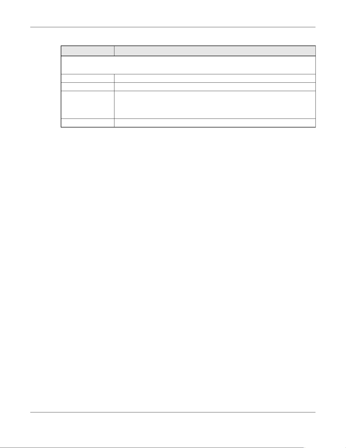
Chapter 37 OAM
XGS2220 Series User’s Guide
274
37.2.1 OAM Details
Use this screen to view OAM configuration details and operational status of a specific port. Click a
number in the Port column in the PORT > OAM > OAM Status screen to display the screen as shown next.
Remote
This section displays information about the remote device.
Mac Address This field displays the MAC address of the remote device.
OUI This field displays the OUI (first 3 bytes of the MAC address) of the remote device.
Mode This field displays the operational state of the port when OAM is enabled on the port.
Active – Allows the port to issue and respond to Ethernet OAM commands.
Passive – Allows the port to respond to Ethernet OAM commands.
Config This field displays the capabilities of the Switch and remote device.
Table 128 PORT > OAM > OAM Status (continued)
LABEL DESCRIPTION
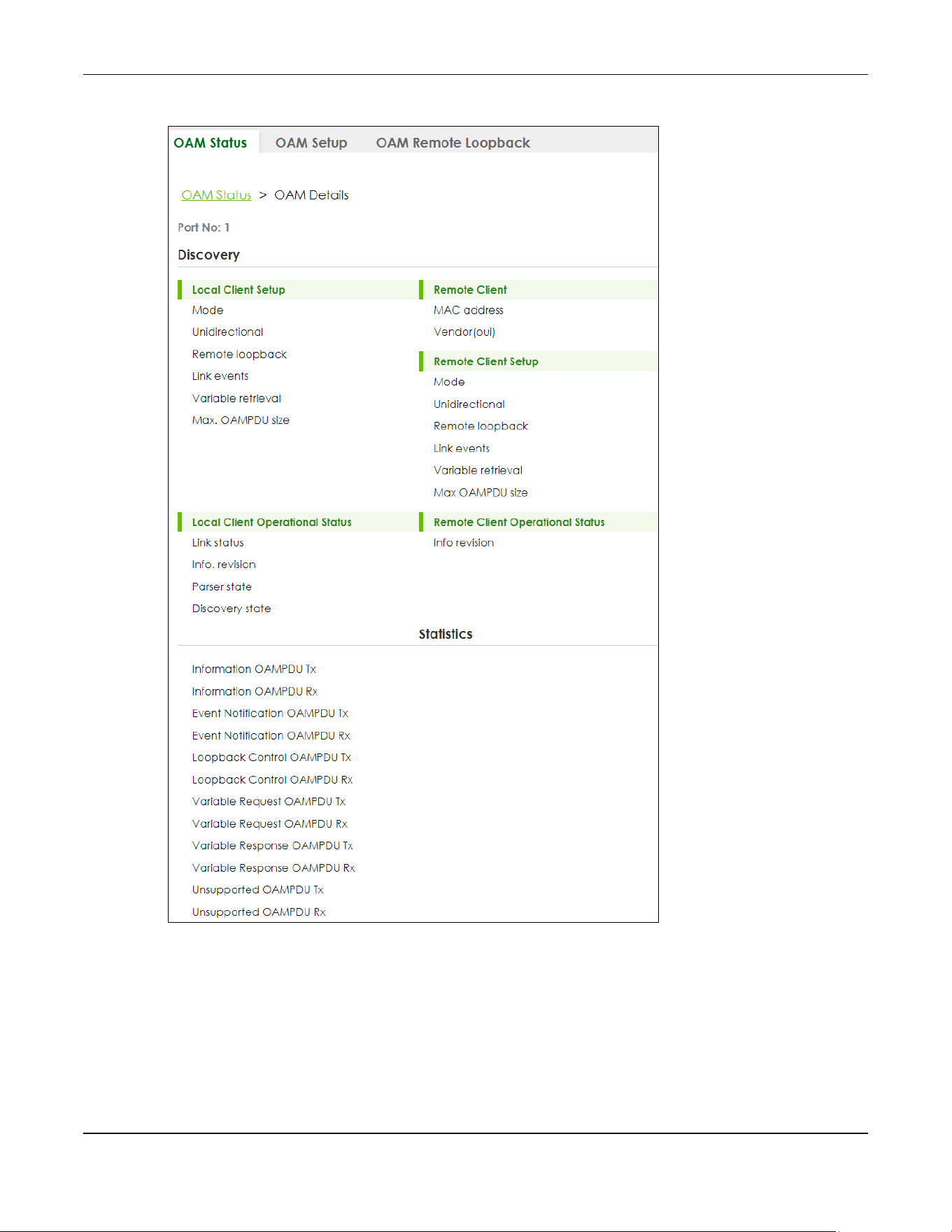
Chapter 37 OAM
XGS2220 Series User’s Guide
275
Figure 203 PORT > OAM > OAM Status > OAM Details

Chapter 37 OAM
XGS2220 Series User’s Guide
276
The following table describes the fields in the above screen.
Table 129 PORT > OAM > OAM Status > OAM Details
LABEL DESCRIPTION
Port No This field displays the port number. In Stacking mode, the first number represents the slot ID
and the second is the port number.
Discovery
This section displays OAM configuration details and operational status of the port on the Switch and/or the remote
device.
Local Client/Remote Client Setup
Mode This field displays the OAM mode. The device in active mode (typically the service
provider's device) controls the device in passive mode (typically the subscriber's device).
Active: The port initiates OAM discovery; sends information PDUs; and may send event
notification PDUs, variable request/response PDUs, or loopback control PDUs.
Passive: The port waits for the remote device to initiate OAM discovery; sends information
PDUs; may send event notification PDUs; and may respond to variable request PDUs or
loopback control PDUs.
The Switch might not support some types of PDUs, as indicated in the fields below.
Unidirectional This field indicates whether or not the port can send information PDUs to transmit fault
information when the receive path is non-operational.
Remote loopback This field indicates whether or not the port can use loopback control PDUs to put the
remote device into loopback mode.
Link events This field indicates whether or not the port can interpret link events, such as link fault and
dying gasp. Link events are sent in event notification PDUs and indicate when the number
of errors in a given interval (time, number of frames, number of symbols, or number of error
frame seconds) exceeds a specified threshold. Organizations may create organization-
specific link event TLVs as well.
Variable retrieval This field indicates whether or not the port can respond to requests for more information,
such as requests for Ethernet counters and statistics, about link events.
Max. OAMPDU
size
This field displays the maximum size of PDU for receipt and delivery.
Local Client/Remote Client Operational status
Link status This field indicates that the link between the Switch port and a connected IEEE 802.3ah-
enabled remote Ethernet device is up or down.
Info. revision This field displays the current version of local state and configuration. This two-octet value
starts at zero and increments every time the local state or configuration changes.
Parser state This field indicates the current state of the parser.
Forward: The port is forwarding packets normally.
Loopback: The port is in loopback mode.
Discard: The port is discarding non-OAM PDUs because it is trying to or has put the remote
device into loopback mode.

Chapter 37 OAM
XGS2220 Series User’s Guide
277
Discovery state This field indicates the state in the OAM discovery process. OAM-enabled devices use this
process to detect each other and to exchange information about their OAM
configuration and capabilities. OAM discovery is a handshake protocol.
Fault: One of the devices is transmitting OAM PDUs with link fault information, or the
interface is not operational.
Active Send Local: The port is in active mode and is trying to see if the remote device
supports OAM.
Passive Wait: The port is in passive mode and is waiting for the remote device to begin
OAM discovery.
Send Local Remote: This state occurs in the following circumstances.
• The port has discovered the remote device but has not accepted or rejected the
connection yet.
• The port has discovered the remote device and rejected the connection.
Send Local Remote OK: The port has discovered the remote device and has accepted the
connection. In addition, the remote device has not accepted or rejected the connection
yet, or the remote device has rejected the connected.
Send Any: The port and the remote device have accepted the connection. This is the
operating state for OAM links that are fully operational.
Remote Client
MAC Address This field displays the MAC address of the IEEE 802.3ah-enabled remote Ethernet device
that is connected to the Switch.
Vendor(oui) This field displays the Organizationally Unique Identifiers (OUI) representing the vendor of
the IEEE 802.3ah-enabled remote Ethernet device that is connected to the Switch.
Statistics
This section displays the number of OAM packets transferred on the port of the Switch.
Information OAMPDU
Tx
This field displays the number of OAM PDUs sent on the port.
Information OAMPDU
Rx
This field displays the number of OAM PDUs received on the port.
Event Notification
OAMPDU Tx
This field displays the number of unique or duplicate OAM event notification PDUs sent on
the port.
Event Notification
OAMPDU Rx
This field displays the number of unique or duplicate OAM event notification PDUs received
on the port.
Loopback Control
OAMPDU Tx
This field displays the number of loopback control OAM PDUs sent on the port.
Loopback Control
OAMPDU Rx
This field displays the number of loopback control OAM PDUs received on the port.
Variable Request
OAMPDU Tx
This field displays the number of OAM PDUs sent to request MIB objects on the remote
device.
Variable Request
OAMPDU Rx
This field displays the number of OAM PDUs received requesting MIB objects on the Switch.
Variable Response
OAMPDU Tx
This field displays the number of OAM PDUs sent by the Switch in response to requests.
Variable Response
OAMPDU Rx
This field displays the number of OAM PDUs sent by the remote device in response to
requests.
Table 129 PORT > OAM > OAM Status > OAM Details (continued)
LABEL DESCRIPTION

Chapter 37 OAM
XGS2220 Series User’s Guide
278
37.3 OAM Setup
Use this screen to turn on Ethernet OAM on the Switch and ports and configure the related settings.
Click PORT > OAM > OAM Setup to display the configuration screen as shown.
Figure 204 PORT > OAM > OAM Setup (Standalone Mode)
Unsupported
OAMPDU Tx
This field displays the number of unsupported OAM PDUs sent on the port.
Unsupported
OAMPDU Rx
This field displays the number of unsupported OAM PDUs received on the port.
Table 129 PORT > OAM > OAM Status > OAM Details (continued)
LABEL DESCRIPTION

Chapter 37 OAM
XGS2220 Series User’s Guide
279
Figure 205 PORT > OAM > OAM Setup (Stacking Mode)
The following table describes the fields in the above screen.
Table 130 PORT > OAM > OAM Setup
LABEL DESCRIPTION
Active Enable the switch button to enable Ethernet OAM on the Switch.
SLOT This field appears only in Stacking mode. Click the drop-down list to choose the slot
number of the Switch in a stack.
Port This field displays the port number. In Stacking mode, the first number represents the slot ID
and the second is the port number. Please note that the default stacking ports (the last
four ports of your Switch) cannot be configured. They are reserved for stacking only.
* Settings in this row apply to all ports.
Use this row only if you want to make some settings the same for all ports. Use this row first to
set the common settings and then make adjustments on a port-by-port basis.
Note: Changes in this row are copied to all the ports as soon as you make them.
Active Select this check box to enable Ethernet OAM on this port.
Clear this check box to disable Ethernet OAM on the port.
Mode Specify the OAM mode on the port.
Select Active to allow the port to issue and respond to Ethernet OAM commands.
Select Passive to allow the port to respond to Ethernet OAM commands.
Remote Loopback
Supported
Select this check box to enable the remote loopback feature on the port. Otherwise, clear
the check box to disable it.
Remote Loopback
Ignore-Rx
Select this check box to set the Switch to process loopback commands received on the
port. Otherwise, clear the check box to have the Switch ignore loopback commands
received on the port.
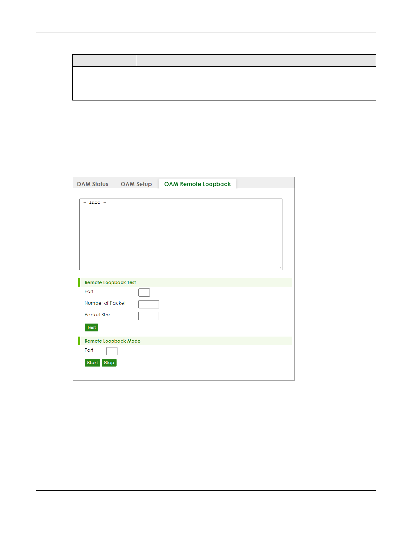
Chapter 37 OAM
XGS2220 Series User’s Guide
280
37.4 OAM Remote Loopback
Use this screen to perform a remote loopback test. Click PORT > OAM > OAM Remote Loopback to
display the screen as shown.
Figure 206 PORT > OAM > OAM Remote Loopback (Standalone Mode)
Apply Click Apply to save your changes to the Switch’s run-time memory. The Switch loses these
changes if it is turned off or loses power, so use the Save link on the top navigation panel to
save your changes to the non-volatile memory when you are done configuring.
Cancel Click Cancel to begin configuring this screen afresh.
Table 130 PORT > OAM > OAM Setup (continued)
LABEL DESCRIPTION
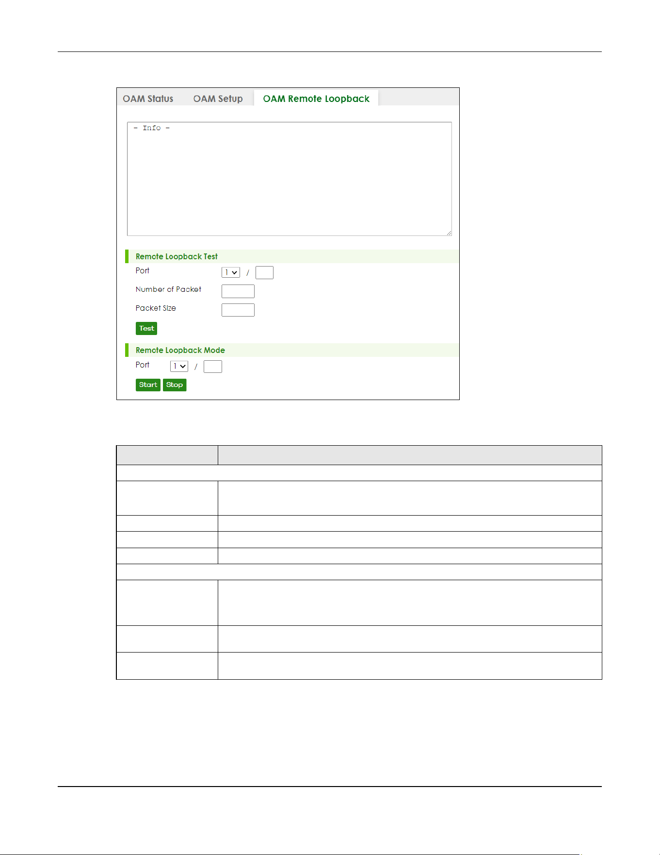
Chapter 37 OAM
XGS2220 Series User’s Guide
281
Figure 207 PORT > OAM > OAM Remote Loopback (Stacking Mode)
The following table describes the fields in the above screen.
Table 131 PORT > OAM > OAM Remote Loopback
LABEL DESCRIPTION
Remote Loopback Test
Port Enter the number of the port from which the Switch performs a remote-loopback test.
In Stacking mode, the first field is the slot ID and the second field is the port number.
Number of Packet Define the allowable packet number of the loopback test frames.
Packet Size Define the allowable packet size of the loopback test frames.
Test Click Test to begin the test.
Remote Loopback Mode
Port Enter the number of the port from which the Switch sends loopback control PDUs to initiate
or terminate a remote-loopback test.
In Stacking mode, the first field is the slot ID and the second field is the port number.
Start Click Start to initiate a remote-loopback test from the specified port by sending Enable
Loopback Control PDUs to the remote device.
Stop Click Stop to terminate a remote-loopback test from the specified port by sending Disable
Loopback Control PDUs to the remote device.

Chapter 38 PoE Setup
XGS2220 Series User’s Guide
282
CHAPTER 38
PoE Setup
38.1 PoE Status (for PoE models only)
Note: The following screens are available for the PoE models only.
The PoE models supports the IEEE 802.3bt High Power over Ethernet (PoE) standard.
A powered device (PD) is a device such as an access point or a switch, that supports PoE (Power over
Ethernet) so that it can receive power from another device through an Ethernet port.
In the figure below, the IP camera and IP phone get their power directly from the Switch. Aside from
minimizing the need for cables and wires, PoE removes the hassle of trying to find a nearby electric
outlet to power up devices.
Figure 208 Powered Device Examples
You can also set priorities so that the Switch is able to reserve and allocate power to certain PDs.
Note: The PoE (Power over Ethernet) devices that supply or receive power and their
connected Ethernet cables must all be completely indoors.

Chapter 38 PoE Setup
XGS2220 Series User’s Guide
283
Figure 209 PORT > PoE Setup > PoE Status (Standalone Mode)
Figure 210 PORT > PoE Setup > PoE Status (Stacking Mode)
The following table describes the labels in this screen.
Table 132 PORT > PoE Setup > PoE Status
LABEL DESCRIPTION
PoE Mode This field displays the power management mode used by the Switch, whether it is in
Classification or Consumption mode.
Total Power (W) This field displays the total power the Switch can provide to the connected PoE-enabled
devices on the PoE ports.
PoE Usage (%) This field displays the amount of power currently being supplied to connected PoE devices (PDs)
as a percentage of the total PoE power the Switch can supply.
When PoE usage reaches 100%, the Switch will shut down PDs one-by-one according to the PD
priority which you configured in PORT > PoE Setup > PoE Setup.
PoE Usage
Threshold (%)
This field displays the percentage of PoE usage. The Switch will generate a trap and/or a log
when the usage exceeds the specified threshold.

Chapter 38 PoE Setup
XGS2220 Series User’s Guide
284
Consuming
Power (W)
This field displays the amount of power the Switch is currently supplying to the connected PoE-
enabled devices.
Allocated Power
(W)
This field displays the total amount of power the Switch (in classification mode) has reserved for
PoE after negotiating with the connected PoE devices. It shows NA when the Switch is in
consumption mode.
Consuming Power (W) can be less than or equal but not more than the Allocated Power (W).
Remaining
Power (W)
This field displays the amount of power the Switch can still provide for PoE.
SLOT This field appears only in stacking mode. Click the drop-down list to choose the slot number of
the Switch in a stack.
Port The port number identifies the port you are configuring. In stacking mode, the first number
represents the slot ID and the second one is the port number. Please note that the default
stacking ports (the last two ports of your Switch) cannot be configured. They are reserved for
stacking only.
State This field shows which ports can receive power from the Switch.
• Disable – The PD connected to this port cannot get power supply.
• Enable – The PD connected to this port can receive power.
Class This shows the power classification of the PD. Each PD has a specified maximum power that fall
under one of the classes.
The Class is a number from 0 to 6, where each value represents the range of power that the
Switch provides to the PD. The power ranges in PoE standards are as follows.
• Class 0 – default: 0.44 W to 15.4 W.
• Class 1 – default: 0.44 W to 4 W.
• Class 2 – default: 0.44 W to 7 W.
• Class 3 – default: 0.44 W to 15.4 W.
• Class 4 – default: 0.44 W to 30 W.
• Class 5 – default: 0.45 W to 45 W.
• Class 6 – default: 0.45 W to 60 W.
Note: You can extend or set a limit on the maximum power the connected PD can
use on a port in PORT > PoE Setup > PoE Setup.
Priority When the total power requested by the PDs exceeds the total PoE power budget on the Switch,
you can set the priority to allow the Switch to provide power to ports with higher priority first.
• Critical has the highest priority.
• High has the Switch assign power to the port after all critical priority ports are served.
• Low has the Switch assign power to the port after all critical and high priority ports are
served.
Power-Up This field displays the PoE standard the Switch uses to provide power on this port.
Consuming
Power (W)
This field displays the current amount of power consumed by the PD from the Switch on this port.
Max Power (W) This field displays the maximum amount of power the PD could use from the Switch on this port.
This field displays “–” if the maximum power is not specified in PORT > PoE Setup > PoE Setup.
Time-Range
State
This field shows whether or not the port currently receives power from the Switch according to its
schedule.
• It shows “In” followed by the time range name if PoE is currently enabled on the port.
• It shows “Out” if PoE is currently disabled on the port.
• It shows “–” if no schedule is applied to the port. PoE is enabled by default.
Table 132 PORT > PoE Setup > PoE Status (continued)
LABEL DESCRIPTION
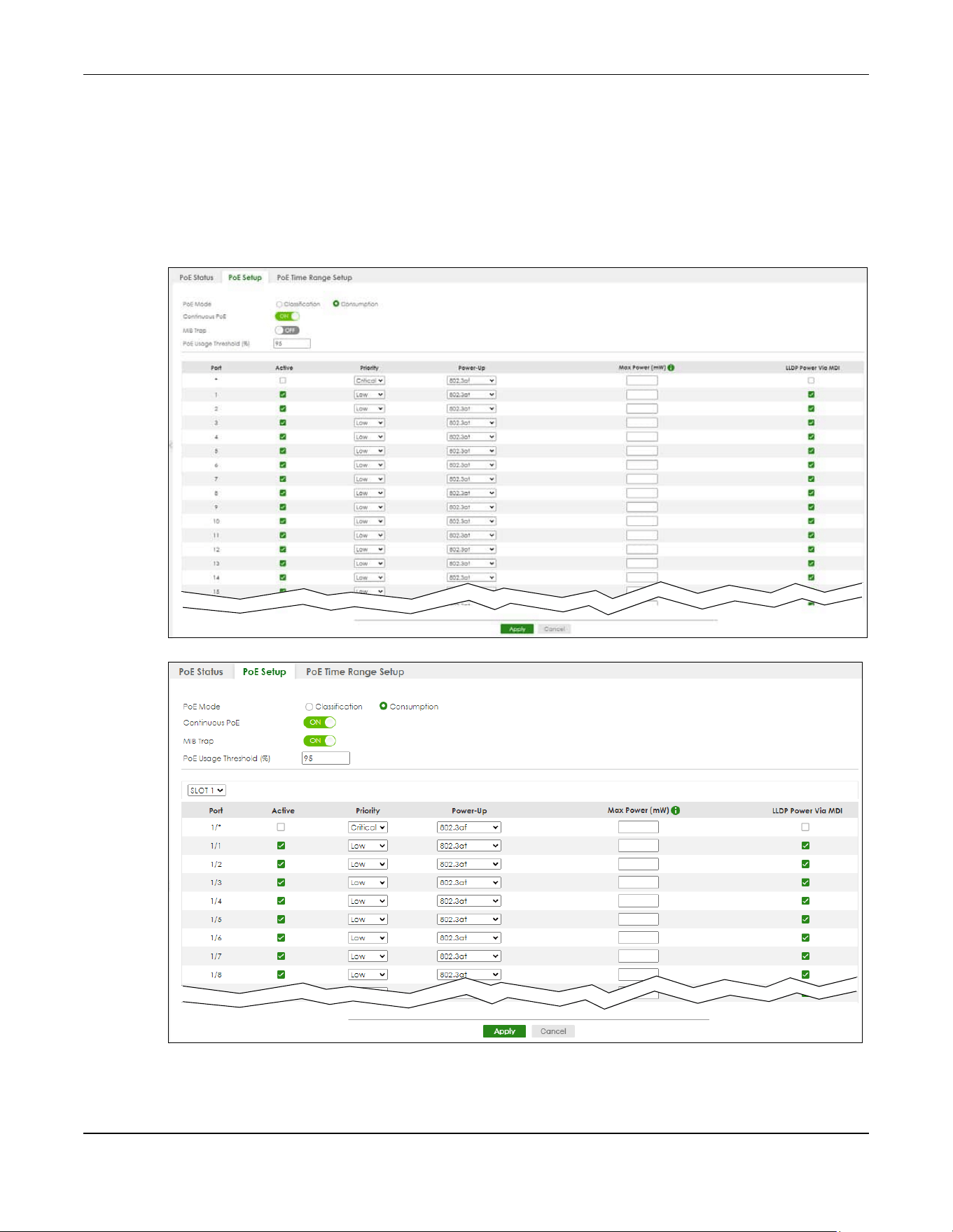
Chapter 38 PoE Setup
XGS2220 Series User’s Guide
285
38.2 PoE Setup
Use this screen to set the PoE power management mode, priority levels, power-up mode and the
maximum amount of power for the connected PDs.
Click the PoE Setup tab in the PORT > PoE Setup screen. The following screen opens.
Figure 211 PORT > PoE Setup > PoE Setup (Standalone Mode)
Figure 212 PORT > PoE Setup > PoE Setup (Stacking Mode)

Chapter 38 PoE Setup
XGS2220 Series User’s Guide
286
The following table describes the labels in this screen.
Table 133 PORT > PoE Setup > PoE Setup
LABEL DESCRIPTION
PoE Mode Select the power management mode you want the Switch to use.
• Classification – Select this if you want the Switch to reserve the maximum power for each PD
according to the PD’s power class and priority level. If the total power supply runs out, PDs
with lower priority do not get power to function. In this mode, the maximum power is reserved
based on what you configure in Max Power or the standard power limit for each class.
• Consumption – Select this if you want the Switch to supply the actual power that the PD
needs. The Switch also allocates power based on a port’s Max Power and the PD’s power
class and priority level. The Switch puts a limit on the maximum amount of power the PD can
request and use. In this mode, the default maximum power that can be delivered to the PD is
30 W (IEEE 802.3at Class 4) or 22 W (IEEE 802.3af Classes 0 to 3).
Continuous
PoE
Select ON to guarantee continuous power supply to the connected PDs while the Switch is
restarting after a warm reboot. The Switch will NOT perform a power cycle on the connected PDs.
If you do a cold reboot, the Switch also restarts the connected PDs.
MIB Trap The Switch sends traps (monitoring event notification) to an SNMP (Simple Network Management
Protocol) manager when an event occurs. See Section 26.6.1 on page 198 for more information
on SNMP, MIB (Management Information Base), and SNMP traps.
Select ON to allow sending of MIB Trap when the following situations occur:
• Situation 1 –
Trap sent whenever a PoE port status change occurs (PoE port delivers power or delivers no
power to a PD (powered device)
• Situation 2 –
Trap sent in cases where the total power usage exceeds the PoE usage threshold
• Situation 3 –
Trap sent if total usage power decreases below the PoE usage threshold (only if previous total
power usage exceeded the PoE usage threshold and a trap was sent).
Note: If the MIB Trap is ON, you must also configure:
• SNMP trap destination (SYSTEM > SNMP > SNMP), SNMP trap group (SYSTEM > SNMP > SNMP
Trap Group) and SNMP trap port (SYSTEM > SNMP > SNMP Trap Port) for Situation 1
• SNMP trap destination and SNMP trap group for Situation 2 and Situation 3.
See Section 26.2 on page 192 for more information on configuring SNMP.
PoE Usage
Threshold (%)
Enter a number ranging from 1 to 99 to set the threshold. The Switch will generate a trap and/or
log when the actual PoE usage is higher than the specified threshold.
SLOT This field appears only in stacking mode. Click the drop-down list to choose the slot number of the
Switch in a stack.
Port The port number identifies the port you are configuring. In stacking mode, the first number
represents the slot ID and the second one is the port number. Please note that the default
stacking ports (the last two ports of your Switch) cannot be configured. They are reserved for
stacking only.
* Settings in this row apply to all ports.
Use this row only if you want to make some settings the same for all ports. Use this row first to set
the common settings and then make adjustments on a port-by-port basis.
Changes in this row are copied to all the ports as soon as you make them.
Active Select this to provide power to a PD connected to the port.
If left unchecked, the PD connected to the port cannot receive power from the Switch.

Chapter 38 PoE Setup
XGS2220 Series User’s Guide
287
Priority When the total power requested by the PDs exceeds the total PoE power budget on the Switch,
you can set the PD priority to allow the Switch to provide power to ports with higher priority.
Select Critical to give the highest PD priority on the port.
Select High to set the Switch to assign the remaining power to the port after all critical priority
ports are served.
Select Low to set the Switch to assign the remaining power to the port after all critical and high
priority ports are served.
Power-Up Set how the Switch provides power to a connected PD at power-up.
802.3af – the Switch follows the IEEE 802.3af Power over Ethernet standard to supply power to the
connected PDs during power-up.
Legacy – the Switch can provide power to the connected PDs that require high inrush currents at
power-up. Inrush current is the maximum, instantaneous input current drawn by the PD when first
turned on.
Pre-802.3at – the Switch initially offers power on the port according to the IEEE 802.3af standard,
and then switches to support the IEEE 802.3at standard within 75 milliseconds after a PD is
connected to the port. Select this option if the Switch is performing 2-event Layer-1 classification
(PoE+ hardware classification) or the connected PD is NOT performing Layer 2 power
classification using Link Layer Discovery Protocol (LLDP).
802.3at – the Switch supports the IEEE 802.3at High Power over Ethernet standard and can supply
power of up to 30 W per Ethernet port. IEEE 802.3at is also known as PoE+ or PoE Plus. An IEEE
802.3at compatible device is referred to as Type 2. Power Class 4 (High Power) can only be used
by Type 2 devices. If the connected PD requires a Class 4 current when it is turned on, it will be
powered up in this mode.
Force-802.3at – the Switch offers power of up to 33 W on the port without performing PoE
hardware classification. Select this option if the connected PD does not comply with any PoE
standard and requests power higher than a standard power limit.
Pre-802.3bt – the Switch offers power on the port according to the IEEE 802.3bt standard. Select
this option if the connected PD was developed before the IEEE 802.3bt standard is implemented
but requires power between 33 W and 60 W. IEEE 802.3bt is also known as PoE++ or PoE Plus Plus.
802.3bt – the Switch supports the IEEE 802.3bt standard and can supply power of up to 60 W per
Ethernet port to the connected PDs at power-up.
Max Power
(mW)
Specify the maximum amount of power the PD could use from the Switch on this port. If you leave
this field blank, the Switch refers to the standard or default maximum power for each class.
Note: The setting you enter here will NOT take effect when the power-up mode is set to
802.3bt.
LLDP Power Via
MDI
Select this to have the Switch negotiate PoE power with the PD connected to the port by
transmitting LLDP Power Via MDI TLV frames. This helps the Switch allocate less power to the PD on
this port. The connected PD must be able to request PoE power through LLDP.
The Power Via MDI TLV allows PoE devices to advertise and discover the MDI power support
capabilities of the sending port on the remote device.
•Port Class
• MDI Supported
•MDI Enabled
• Pair Controllable
• PSE Power Pairs
•Power Class
Table 133 PORT > PoE Setup > PoE Setup (continued)
LABEL DESCRIPTION

Chapter 38 PoE Setup
XGS2220 Series User’s Guide
288
38.3 PoE Time Range Setup
Use this screen to apply a schedule to the ports on the Switch. You must first configure a schedule in the
SYSTEM > Time Range screen.
Figure 213 PORT > PoE Setup > PoE Time Range Setup (Standalone Mode)
Figure 214 PORT > PoE Setup > PoE Time Range Setup (Stacking Mode)
The following table describes the labels in this screen.
Apply Click Apply to save your changes to the Switch’s run-time memory. The Switch loses these
changes if it is turned off or loses power, so use the Save link on the top navigation panel to save
your changes to the non-volatile memory when you are done configuring.
Cancel Click Cancel to begin configuring this screen afresh.
Table 133 PORT > PoE Setup > PoE Setup (continued)
LABEL DESCRIPTION
Table 134 PORT > PoE Setup > PoE Time Range Setup
LABEL DESCRIPTION
SLOT This field appears only in stacking mode. Click the drop-down list to choose the slot number of the
Switch in a stack.
Port The port number identifies the port you are configuring. In stacking mode, the first number
represents the slot ID and the second one is the port number. Please note that the default
stacking ports (the last two ports of your Switch) cannot be configured. They are reserved for
stacking only.
Time Range
Profiles
This field displays the name of the schedule which is applied to the port.
PoE is enabled at the specified time or date.

Chapter 38 PoE Setup
XGS2220 Series User’s Guide
289
38.3.1 Add/Edit PoE Time Range
To access this screen, click the Add/Edit button or select an entry from the list and click the Add/Edit
button.
Figure 215 PORT > PoE Setup > PoE Time Range Setup > Add/Edit (Standalone Mode)
Figure 216 PORT > PoE Setup > PoE Time Range Setup > Add/Edit (Stacking Mode)
The following table describes the labels in this screen.
Select an entry’s check box to select a specific entry. Otherwise, select the check box in the
table heading row to select all entries.
Add/Edit Click Add/Edit to add a new rule or edit a selected one.
Delete Check the rules that you want to remove and then click the Delete button.
Table 134 PORT > PoE Setup > PoE Time Range Setup (continued)
LABEL DESCRIPTION
Table 135 PORT > PoE Setup > PoE Time Range Setup > Add/Edit
LABEL DESCRIPTION
Port The port number identifies the port you are configuring. In stacking mode, the first number
represents the slot ID and the second one is the port number. Please note that the default
stacking ports (the last two ports of your Switch) cannot be configured. They are reserved for
stacking only.
Time Range This field displays the name of the schedule that you have created using the SYSTEM > Time
Range screen.
Select a pre-defined schedule to control when the Switch enables PoE to provide power on
the port. To select more than one schedule, press [SHIFT] and select the choices at the same
time.
Apply Click Apply to save your changes to the Switch’s run-time memory. The Switch loses these
changes if it is turned off or loses power, so use the Save link on the top navigation panel to
save your changes to the non-volatile memory when you are done configuring.

Chapter 38 PoE Setup
XGS2220 Series User’s Guide
290
Clear Click Clear to clear the fields to the factory defaults.
Cancel Click Cancel to not save the configuration you make and return to the last screen.
Table 135 PORT > PoE Setup > PoE Time Range Setup > Add/Edit (continued)
LABEL DESCRIPTION
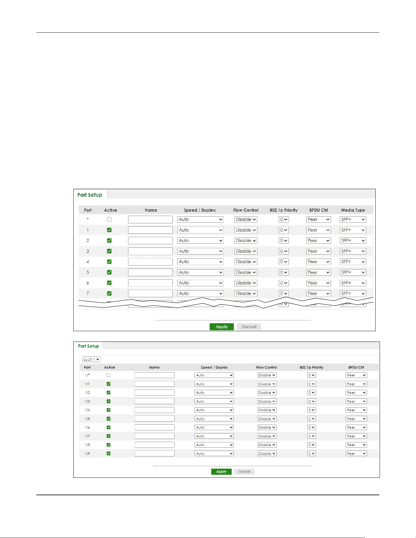
Chapter 39 Port Setup
XGS2220 Series User’s Guide
291
CHAPTER 39
Port Setup
39.1 Port Setup
Use this screen to configure Switch port settings. Click PORT > Port Setup > Port Setup in the navigation
panel to display the configuration screen.
Figure 217 PORT > Port Setup (Standalone Mode)
Figure 218 PORT > Port Setup (Stacking Mode)

Chapter 39 Port Setup
XGS2220 Series User’s Guide
292
The following table describes the labels in this screen.
Table 136 PORT > Port Setup > Port Setup
LABEL DESCRIPTION
SLOT This field appears only in Stacking mode. Click the drop-down list to choose the slot number of
the Switch in a stack.
Port This is the port index number. In Stacking mode, the first number represents the slot ID and the
second one is the port number. Please note that the default stacking ports (the last four ports of
your Switch) cannot be configured. They are reserved for stacking only.
* Settings in this row apply to all ports.
Use this row only if you want to make some settings the same for all ports. Use this row first to set
the common settings and then make adjustments on a port-by-port basis.
Note: Changes in this row are copied to all the ports as soon as you make them.
Active Select this check box to enable a port. The factory default for all ports is enabled. A port must
be enabled for data transmission to occur.
Name Type a descriptive name that identifies this port. You can enter up to 128 printable ASCII
characters except [ ? ], [ | ], [ ' ] or [ " ].
Note: Due to space limitations, the port name may be truncated in some Web
Configurator screens.
Speed/Duplex Select the speed and the duplex mode of the Ethernet connection on this port.
For an Ethernet port, the choices are Auto, 10-an (10M/auto-negotiation), 10M/Full Duplex, 100-
an (100M/auto-negotiation), 100M/Full Duplex, 1G/Full Duplex, 2.5G/Full Duplex, 5G/Full
Duplex, and 10G/Full Duplex (Gigabit connections only).
For an SFP+ interface, the choices are Auto, Auto-1G, 1G/Full Duplex, and 10G/Full Duplex
(Gigabit connections only).
Selecting Auto-1G or Auto (auto-negotiation) allows one port to negotiate with a peer port
automatically to obtain the connection speed and duplex mode that both ends support. When
auto-negotiation is turned on, a port on the Switch negotiates with the peer automatically to
determine the connection speed and duplex mode. If the peer port does not support auto-
negotiation or turns off this feature, the Switch determines the connection speed by detecting
the signal on the cable and using half duplex mode. When the Switch’s auto-negotiation is
turned off, a port uses the pre-configured speed and duplex mode when making a connection,
thus requiring you to make sure that the settings of the peer port are the same in order to
connect.

Chapter 39 Port Setup
XGS2220 Series User’s Guide
293
Flow Control A concentration of traffic on a port decreases port bandwidth and overflows buffer memory
causing packet discards and frame losses. Flow Control is used to regulate transmission of signals
to match the bandwidth of the receiving port.
The Switch uses IEEE 802.3x flow control in full duplex mode and backpressure flow control in half
duplex mode.
IEEE 802.3x flow control is used in full duplex mode to send a pause signal to the sending port,
causing it to temporarily stop sending signals when the receiving port memory buffers fill.
Back Pressure flow control is typically used in half duplex mode to send a "collision" signal to the
sending port (mimicking a state of packet collision) causing the sending port to temporarily stop
sending signals and resend later.
Select Tx Rx to allow the Switch port to send pause signal to the connected device, and for the
connected device to send a pause signal to the Switch. The Switch will temporarily stop sending
signals after receiving pause signal.
Select Tx to allow the Switch port to send pause signal to the connected device.
Select Rx to allow the connected device to send a pause signal to the Switch. The Switch will
temporarily stop sending signals.
Otherwise, select Disable.
802.1p Priority This priority value is added to incoming frames without a (802.1p) tag.
BPDU Ctrl Configure the way to treat BPDUs received on this port. You must activate Bridging Control
Protocol Transparency in the SYSTEM > Switch Setup screen first.
Select Peer to process any BPDU (Bridge Protocol Data Units) received on this port.
Select Tunnel to forward BPDUs received on this port.
Select Discard to drop any BPDU received on this port.
Select Network to process a BPDU with no VLAN tag and forward a tagged BPDU.
Media Type You can insert either an SFP+ transceiver or an SFP+ Direct Attach Copper (DAC) cable into the
10 Gigabit interface of the Switch.
Select the media type (SFP+ or DAC10G) of the SFP+ module that is attached to the 10 Gigabit
interface.
Apply Click Apply to save your changes to the Switch’s run-time memory. The Switch loses these
changes if it is turned off or loses power, so use the Save link on the top navigation panel to save
your changes to the non-volatile memory when you are done configuring.
Cancel Click Cancel to begin configuring this screen afresh.
Table 136 PORT > Port Setup > Port Setup (continued)
LABEL DESCRIPTION
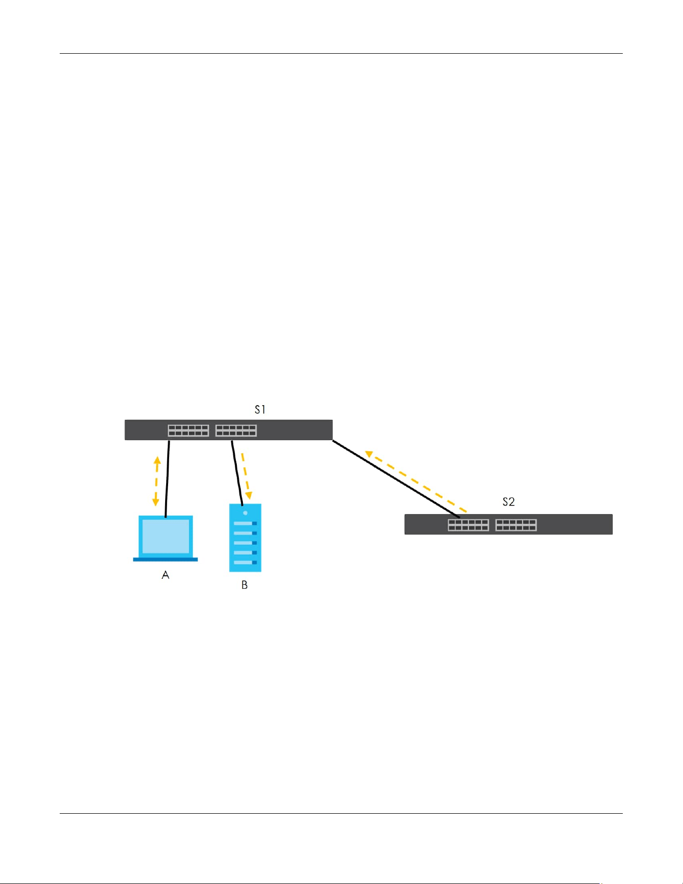
Chapter 40 ZULD
XGS2220 Series User’s Guide
294
CHAPTER 40
ZULD
40.1 ZULD Overview
A unidirectional link is a connection where the link is up on both ends, but only one end can receive
packets. This may happen if OAM was initially enabled but then disabled, there are mis-configured
transmitting or receiving lines or the hardware is malfunctioning. Zyxel Unidirectional Link Detection
(ZULD) is a layer-2 protocol that can detect and disable these physical one-way links before they cause
loops or communication malfunction.
In the figure below, S1–A is a bidirectional link as both ends can send packets to each other. S1–B is
unidirectional as B cannot send packets to S1 (although the S1–B link is up). Similarly, S2–S1 is
unidirectional as S1 cannot send packets to S2 (although the S1–S2 link is up).
Figure 219 ZULD Overview
40.1.1 What You Can Do
• Use the ZULD Status screen (Section 40.2 on page 295) to see details on ZULD.
• Use the ZULD Setup screen (Section 40.3 on page 297) to enable ZULD on a port, configure a mode
and set the probe time.
40.1.2 What You Need to Know
• ZULD must be enabled on the Switch and the ports in order to detect unidirectional links by monitoring
OAMPDUs.
• Ports advertise their unidirectional link detection capability using OAMPDUs, so all connected devices
must support OAM as well as ZULD. You need to enable OAM on the Switch by going to PORT > OAM
> OAM Setup and enable the switch in the Active field. OAM must be enabled on other connected

Chapter 40 ZULD
XGS2220 Series User’s Guide
295
devices too. If OAM is not enabled initially, ZULD will not work.
• If OAM is enabled initially and later disabled on one end of a link, the link will be unidirectional as that
end cannot send OAMPDUs.
• OAM discovery, the sending of OAMPDUs to other ports, is initiated by an active port.
• When ZULD detects a unidirectional link, it sends a syslog and SNMP trap and may shut down the
affected port (Aggressive Mode).
• If a port on the Switch is shut down by ZULD, and you want to recover it, then do one of the following:
•Go to PORT > Port Setup. Clear Active and click Apply. Then select Active and click Apply again.
•Go to SECURITY > Errdisable > Errdisable Recovery and set the interval for ZULD. After the interval
expires, the closed ports will become active and start receiving packets again.
• Use the command port no inactive.
• Refer to the ZULD logs to see when a unidirectional link is detected and when it is recovered to a
bidirectional link.
40.2 ZULD Status
Use this screen to see details of unidirectional and bidirectional links discovered by ZULD. To open this
screen, click PORT > ZULD > ZULD Status.
Figure 220 PORT > ZULD > ZULD Status (Standalone Mode)
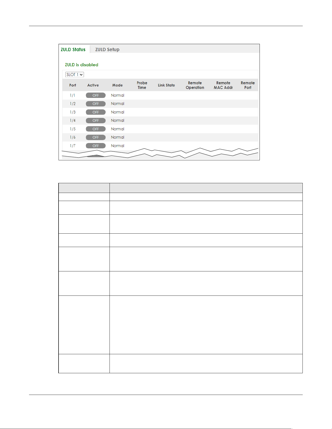
Chapter 40 ZULD
XGS2220 Series User’s Guide
296
Figure 221 PORT > ZULD > ZULD Status (Stacking Mode)
The following table describes the fields in the above screen.
Table 137 PORT > ZULD > ZULD Status
LABEL DESCRIPTION
ZULD is.... This shows whether ZULD is enabled or disabled on the Switch.
SLOT This field appears only in Stacking mode. Click the drop-down list to choose the slot
number of the Switch in a stack.
Port This field displays the port number. In Stacking mode, the first number represents the slot ID
and the second is the port number. Please note that the default stacking ports (the last
four ports of your Switch) cannot be configured. They are reserved for stacking only.
Active This field displays whether ZULD is enabled on the port or not. ZULD must be enabled to
detect an unidirectional link by monitoring OAMPDUs.
Mode This field indicates what ZULD will do when a unidirectional link is detected. In Normal
mode, ZULD only sends a syslog and trap when it detects a unidirectional link. In
Aggressive mode, ZULD shuts down the port (puts it into an ErrDisable state) as well as
sends a syslog and trap when it detects a unidirectional link.
Probe Time Probe time is the length of time that ZULD waits before declaring that a link is
unidirectional. When the probe time expires, and one port (either on the Switch or the
connected device) still has not received an OAMPDU, then ZULD declares that the link is
unidirectional.
Link State This field shows the following link states:
• Linkdown: This is an initialization state, where the port is not yet up.
• Probe: This indicates that ZULD is discovering the connected device on this link.
• Bidirectional: Traffic sent by the Switch is received by the connected device on this
link, and traffic from the connected device on this link is received by the Switch.
• Unidirectional: The state of the link between the port and its connected port cannot
be determined either because no ZULD message was received, or one port is not
capable of sending traffic.
• Shutdown: The port has been shut down because its link with the connected device is
unidirectional and ZULD is in Aggressive mode.
Remote Operation This field displays whether ZULD is enabled or disabled on the connected device on this
link. ZULD must be enabled on the connected device and on the port that is connecting
to the Switch.

Chapter 40 ZULD
XGS2220 Series User’s Guide
297
40.3 ZULD Setup
Use this screen to enable ZULD on a port, configure a mode and set the probe time. To open this screen,
click PORT > ZULD > ZULD Setup.
Figure 222 PORT > ZULD > ZULD Setup (Standalone Mode)
Remote MAC Addr This is the MAC address of the port on the connected device to which the port of the
Switch is connected.
Remote Port This is the port number of the port on the connected device to which the port of the Switch
is connected.
Table 137 PORT > ZULD > ZULD Status (continued)
LABEL DESCRIPTION

Chapter 40 ZULD
XGS2220 Series User’s Guide
298
Figure 223 PORT > ZULD > ZULD Setup (Stacking Mode)
The following table describes the fields in the above screen.
Table 138 PORT > ZULD > ZULD Setup
LABEL DESCRIPTION
Active Enable the switch button to enable ZULD on the Switch.
SLOT This field appears only in Stacking mode. Click the drop-down list to choose the slot
number of the Switch in a stack.
Port This field displays the port number. In Stacking mode, the first number represents the slot ID
and the second is the port number. Please note that the default stacking ports (the last
four ports of your Switch) cannot be configured. They are reserved for stacking only.
* Settings in this row apply to all ports.
Use this row only if you want to make some settings the same for all ports. Use this row first to
set the common settings and then make adjustments on a port-by-port basis.
Note: Changes in this row are copied to all the ports as soon as you make them.
Active Select this to enable ZULD on the port. ZULD must be enabled to detect an unidirectional
link by monitoring OAMPDUs.
Mode Select Normal or Aggressive. In Normal mode, ZULD only sends a syslog and trap when it
detects a unidirectional link. In Aggressive mode, ZULD shuts down the port (puts it into an
ErrDisable state) as well as sends a syslog and trap when it detects a unidirectional link.
Probe Time Type the length of time that ZULD waits before declaring that a link is unidirectional. When
the probe time expires, and one port (either on the Switch or the connected device) still
has not received an OAMPDU, then ZULD declares that the link is unidirectional.
The allowed time range is from 5 – 65535 seconds.

Chapter 40 ZULD
XGS2220 Series User’s Guide
299
Apply Click Apply to save your changes to the Switch’s run-time memory. The Switch loses these
changes if it is turned off or loses power, so use the Save link on the top navigation panel to
save your changes to the non-volatile memory when you are done configuring.
Cancel Click this to reset the values in this screen to their last-saved values.
Table 138 PORT > ZULD > ZULD Setup (continued)
LABEL DESCRIPTION

XGS2220 Series User’s Guide
300
CHAPTER 41
SWITCHING
The following chapters introduces the configurations of the links under the SWITCHING navigation panel.
Quick links to chapters:
• Layer 2 Protocol Tunneling
• Loop Guard
• MAC Pinning
• Mirroring
• Multicast
• Static Multicast Forwarding
• PPPoE
• Differentiated Services
• Queuing Method
• Priority Queue
• Bandwidth Control
• sFlow
• Spanning Tree Protocol
• Static MAC Filtering
• Static MAC Forwarding
• VLAN Isolation
• VLAN Mapping
• VLAN Stacking

Chapter 42 Layer 2 Protocol Tunneling
XGS2220 Series User’s Guide
301
CHAPTER 42
Layer 2 Protocol Tunneling
42.1 Layer 2 Protocol Tunneling Overview
This chapter shows you how to configure layer 2 protocol tunneling on the Switch.
42.1.1 What You Can Do
Use the Layer 2 Protocol Tunneling screen (Section 42.2 on page 302) to enable layer 2 protocol
tunneling on the Switch and specify a MAC address with which the Switch uses to encapsulate the layer
2 protocol packets by replacing the destination MAC address in the packets.
42.1.2 What You Need to Know
Layer 2 protocol tunneling (L2PT) is used on the service provider's edge devices.
L2PT allows edge switches (1 and 2 in the following figure) to tunnel layer 2 STP (Spanning Tree Protocol),
CDP (Cisco Discovery Protocol) and VTP (VLAN Trunking Protocol) packets between customer switches
(A, B and C in the following figure) connected through the service provider’s network. The edge switch
encapsulates layer 2 protocol packets with a specific MAC address before sending them across the
service provider’s network to other edge switches.
Figure 224 Layer 2 Protocol Tunneling Network Scenario
In the following example, if you enable L2PT for STP, you can have switches A, B, C and D in the same
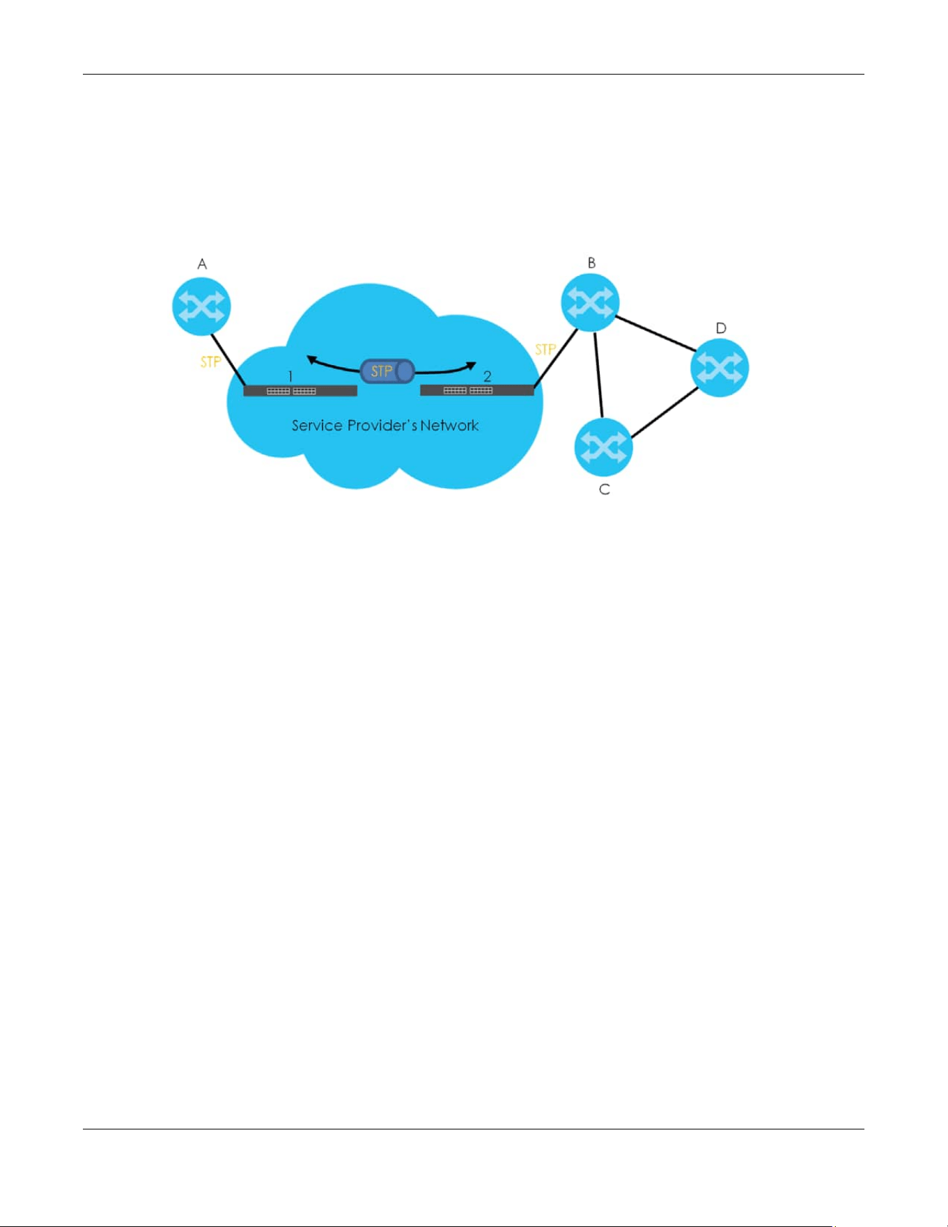
Chapter 42 Layer 2 Protocol Tunneling
XGS2220 Series User’s Guide
302
spanning tree, even though switch A is not directly connected to switches B, C and D. Topology change
information can be propagated throughout the service provider’s network.
To emulate a point-to-point topology between two customer switches at different sites, such as A and B,
you can enable protocol tunneling on edge switches 1 and 2 for PAgP (Port Aggregation Protocol),
LACP or UDLD (Uni-Directional Link Detection).
Figure 225 L2PT Network Example
42.1.2.1 Layer 2 Protocol Tunneling Mode
Each port can have two layer 2 protocol tunneling modes, Access and Tunnel.
• The Access port is an ingress port on the service provider's edge device (1 or 2 in Figure 225 on page
302) and connected to a customer switch (A or B). Incoming layer 2 protocol packets received on an
access port are encapsulated and forwarded to the tunnel ports.
• The Tunnel port is an egress port at the edge of the service provider's network and connected to
another service provider’s switch. Incoming encapsulated layer 2 protocol packets received on a
tunnel port are decapsulated and sent to an access port.
42.2 Configuring Layer 2 Protocol Tunneling
Click SWITCHING > Layer 2 Protocol Tunneling in the navigation panel to display the screen as shown.

Chapter 42 Layer 2 Protocol Tunneling
XGS2220 Series User’s Guide
303
Figure 226 SWITCHING > Layer 2 Protocol Tunneling (Standalone Mode)
Figure 227 SWITCHING > Layer 2 Protocol Tunneling (Stacking Mode)

Chapter 42 Layer 2 Protocol Tunneling
XGS2220 Series User’s Guide
304
The following table describes the labels in this screen.
Table 139 SWITCHING > Layer 2 Protocol Tunneling
LABEL DESCRIPTION
Active Enable the switch button to enable layer 2 protocol tunneling on the Switch.
Destination
MAC Address
Specify a MAC address with which the Switch uses to encapsulate the layer 2 protocol packets
by replacing the destination MAC address in the packets.
Note: The MAC address can be either a unicast MAC address or multicast MAC
address. If you use a unicast MAC address, make sure the MAC address does
not exist in the address table of a switch on the service provider’s network.
Note: All the edge switches in the service provider’s network should be set to use the
same MAC address for encapsulation.
SLOT This field appears only in Stacking mode. Click the drop-down list to choose the slot number of
the Switch in a stack.
Port This field displays the port number. In Stacking mode, the first number represents the slot ID and
the second is the port number. Please note that the default stacking ports (the last four ports of
your Switch) cannot be configured. They are reserved for stacking only.
* Use this row to make the setting the same for all ports. Use this row first and then make
adjustments on a port-by-port basis.
Note: Changes in this row are copied to all the ports as soon as you make them.
CDP Select this option to have the Switch tunnel CDP (Cisco Discovery Protocol) packets so that
other Cisco devices can be discovered through the service provider’s network.
STP Select this option to have the Switch tunnel STP (Spanning Tree Protocol) packets so that STP can
run properly across the service provider’s network and spanning trees can be set up based on
bridge information from all (local and remote) networks.
VTP Select this option to have the Switch tunnel VTP (VLAN Trunking Protocol) packets so that all
customer switches can use consistent VLAN configuration through the service provider’s
network.
LLDP Select this option to have the Switch tunnel LLDP (Link Layer Discovery Protocol) packets so that
all network devices can advertise its identity and capabilities through the service provider’s
network.
Point to Point The Switch supports PAgP (Port Aggregation Protocol), LACP (Link Aggregation Control
Protocol) and UDLD (UniDirectional Link Detection) tunneling for a point-to-point topology.
Both PAgP and UDLD are Cisco’s proprietary data link layer protocols. PAgP is similar to LACP
and used to set up a logical aggregation of Ethernet ports automatically. UDLD is to determine
the link’s physical status and detect a unidirectional link.
PAGP Select this option to have the Switch send PAgP packets to a peer to automatically negotiate
and build a logical port aggregation.
LACP Select this option to have the Switch send LACP packets to a peer to dynamically create and
manage trunk groups.
UDLD Select this option to have the Switch send UDLD packets to a peer’s port it connected to
monitor the physical status of a link.
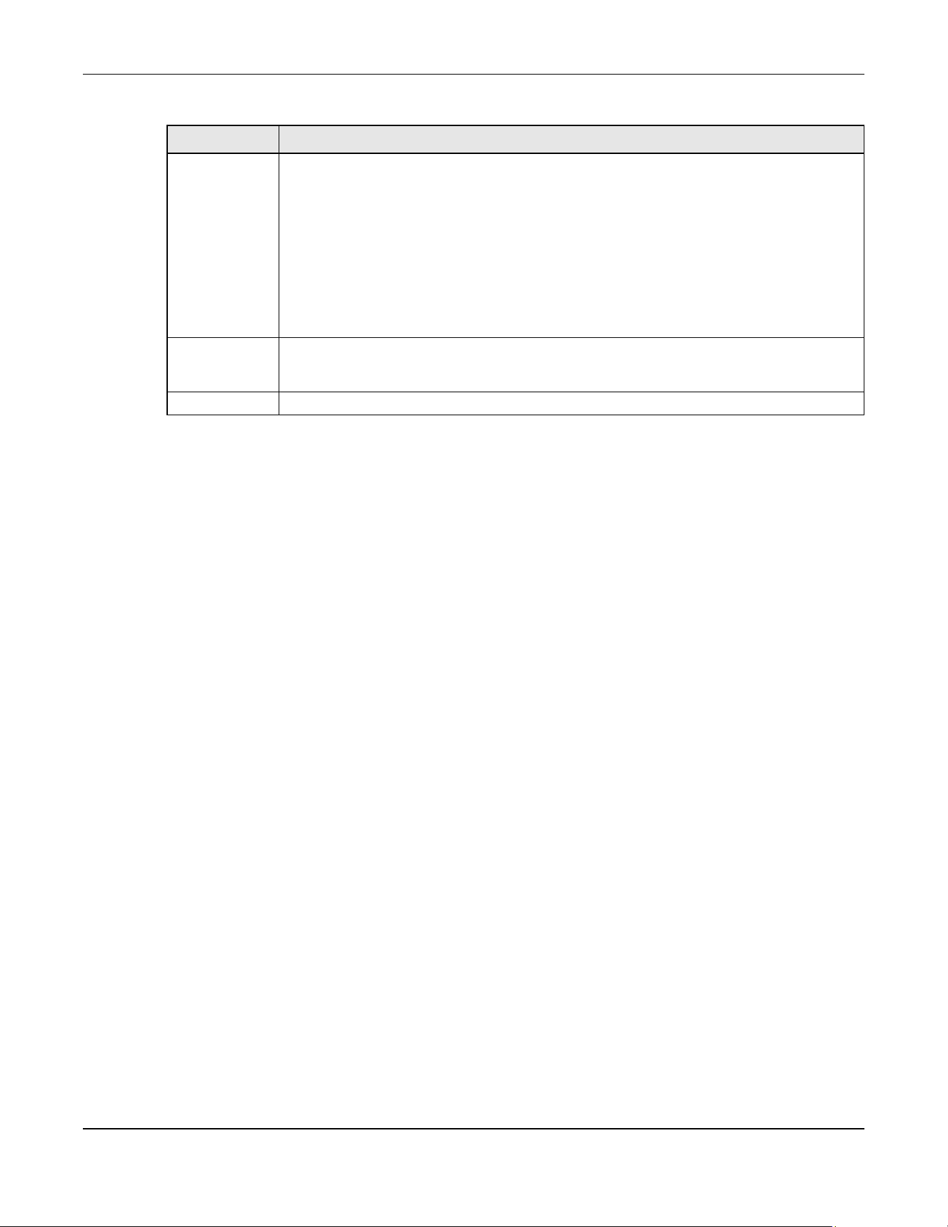
Chapter 42 Layer 2 Protocol Tunneling
XGS2220 Series User’s Guide
305
Mode Select Access to have the Switch encapsulate the incoming layer 2 protocol packets and
forward them to the tunnel ports. Select Access for ingress ports at the edge of the service
provider's network.
Note: You can enable L2PT services for STP, LACP, VTP, CDP, UDLD, PAgP, and LLDP on
the access ports only.
Select Tunnel for egress ports at the edge of the service provider's network. The Switch
decapsulates the encapsulated layer 2 protocol packets received on a tunnel port by
changing the destination MAC address to the original one, and then forward them to an access
port. If the services is not enabled on an access port, the protocol packets are dropped.
Apply Click Apply to save your changes to the Switch’s run-time memory. The Switch loses these
changes if it is turned off or loses power, so use the Save link on the top navigation panel to save
your changes to the non-volatile memory when you are done configuring.
Cancel Click Cancel to begin configuring this screen afresh.
Table 139 SWITCHING > Layer 2 Protocol Tunneling (continued)
LABEL DESCRIPTION
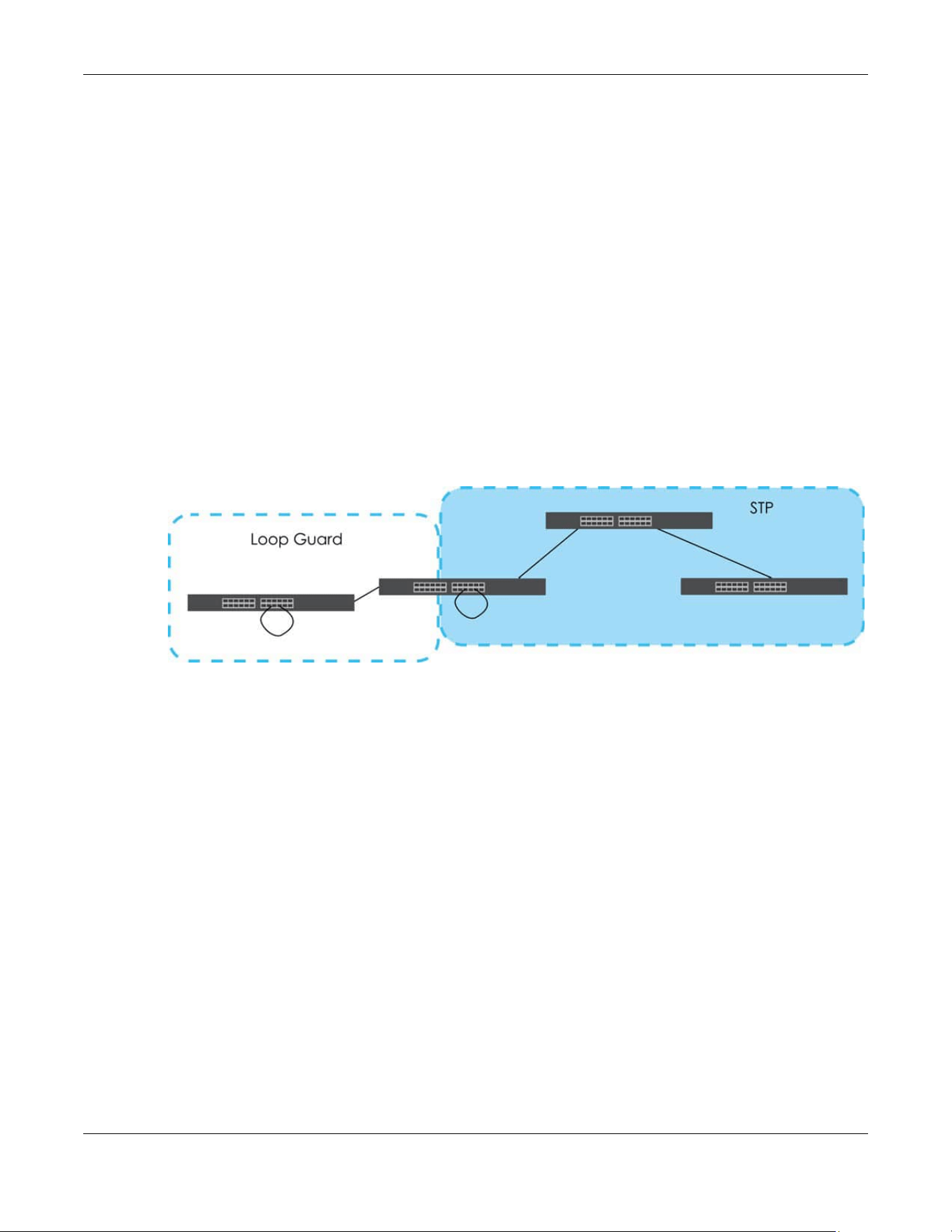
Chapter 43 Loop Guard
XGS2220 Series User’s Guide
306
CHAPTER 43
Loop Guard
43.1 Loop Guard Overview
This chapter shows you how to configure the Switch to guard against loops on the edge of your network.
Loop guard allows you to configure the Switch to shut down a port if it detects that packets sent out on
that port loop back to the Switch. While you can use Spanning Tree Protocol (STP) to prevent loops in the
core of your network. STP cannot prevent loops that occur on the edge of your network.
Figure 228 Loop Guard vs. STP
Refer to Section 43.1.2 on page 306 for more information.
43.1.1 What You Can Do
Use the Loop Guard screen (Section 43.2 on page 308) to enable loop guard on the Switch and in
specific ports.
43.1.2 What You Need to Know
Loop guard is designed to handle loop problems on the edge of your network. This can occur when a
port is connected to a Switch that is in a loop state. Loop state occurs as a result of human error. It
happens when two ports on a switch are connected with the same cable. When a switch in loop state
sends out broadcast messages the messages loop back to the switch and are re-broadcast again and
again causing a broadcast storm.
If a switch (not in loop state) connects to a switch in loop state, then it will be affected by the switch in
loop state in the following way:
• The switch (not in loop state) will receive broadcast messages sent out from the switch in loop state.
• The switch (not in loop state) will receive its own broadcast messages that it sends out as they loop
back. It will then re-broadcast those messages again.

Chapter 43 Loop Guard
XGS2220 Series User’s Guide
307
The following figure shows port N on switch A connected to switch B. Switch B has two ports, x and y,
mistakenly connected to each other. It forms a loop. When broadcast or multicast packets leave port N
and reach switch B, they are sent back to port N on A as they are rebroadcast from B.
Figure 229 Switch in Loop State
The loop guard feature checks to see if a loop guard enabled port is connected to a Switch in loop
state. This is accomplished by periodically sending a probe packet and seeing if the packet returns on
the same port. If this is the case, the Switch will shut down the port connected to the switch in loop state.
Loop guard can be enabled on both Ethernet ports. The following figure shows a loop guard enabled
port N on switch A sending a probe packet P to switch B. Since switch B is in loop state, the probe
packet P returns to port N on A. The Switch then shuts down port N to ensure that the rest of the network
is not affected by the switch in loop state.
Figure 230 Loop Guard – Probe Packet
The Switch also shuts down port N if the probe packet returns to switch A on any other port. In other
words loop guard also protects against standard network loops.
The following figure illustrates three switches forming a loop. A sample path of the loop guard probe
packet is also shown. In this example, the probe packet is sent from port N and returns on another port.
As long as loop guard is enabled on port N. The Switch will shut down port N if it detects that the probe
packet has returned to the Switch.
Figure 231 Loop Guard – Network Loop
Note: After resolving the loop problem on your network you can re-activate the disabled port
through the Web Configurator or through commands (See the CLI Reference Guide).
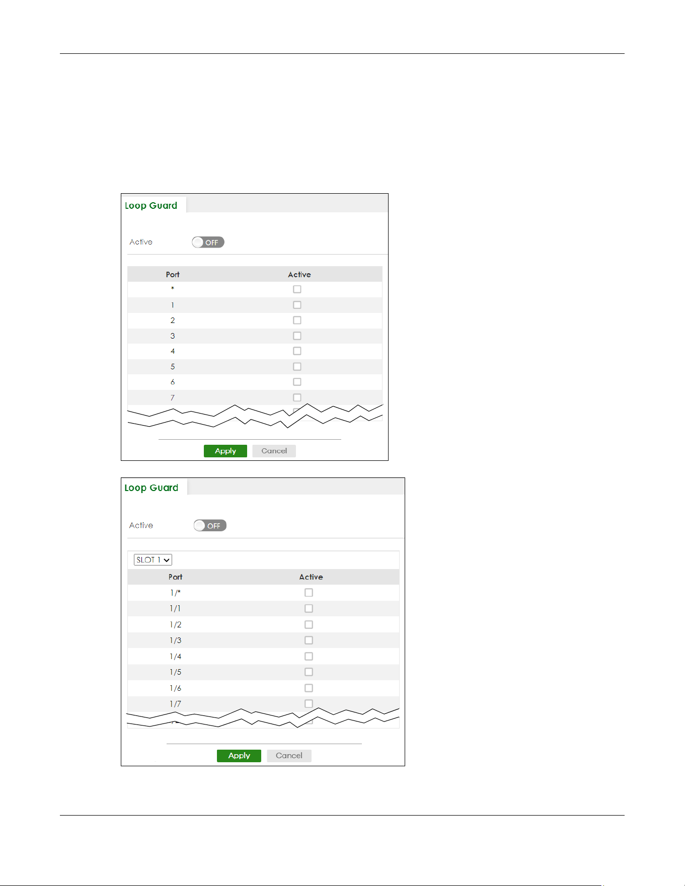
Chapter 43 Loop Guard
XGS2220 Series User’s Guide
308
43.2 Loop Guard Setup
Click SWITCHING > Loop Guard in the navigation panel to display the screen as shown.
Note: The loop guard feature cannot be enabled on the ports that have Spanning Tree
Protocol (RSTP, MRSTP or MSTP) enabled.
Figure 232 SWITCHING > Loop Guard (Standalone Mode)
Figure 233 SWITCHING > Loop Guard (Stacking Mode)

Chapter 43 Loop Guard
XGS2220 Series User’s Guide
309
The following table describes the labels in this screen.
Table 140 SWITCHING > Loop Guard
LABEL DESCRIPTION
Active Enable the switch button to activate loop guard function on the Switch.
The Switch generates syslog, internal log messages as well as SNMP traps when it shuts down a
port through the loop guard feature.
SLOT This field appears only in Stacking mode. Click the drop-down list to choose the slot number of
the Switch in a stack.
Port This field displays the port number. In Stacking mode, the first number represents the slot ID and
the second is the port number. Please note that the default stacking ports (the last four ports of
your Switch) cannot be configured. They are reserved for stacking only.
* Settings in this row apply to all ports.
Use this row only if you want to make some settings the same for all ports. Use this row first to set
the common settings and then make adjustments on a port-by-port basis.
Note: Changes in this row are copied to all the ports as soon as you make them.
Active Select this check box to enable the loop guard feature on this port. The Switch sends broadcast
and multicast probe packets from this port to check if the switch it is connected to is in loop
state. If the switch that this port is connected is in loop state the Switch will shut down this port.
Clear this check box to disable the loop guard feature.
Apply Click Apply to save your changes to the Switch’s run-time memory. The Switch loses these
changes if it is turned off or loses power, so use the Save link on the top navigation panel to save
your changes to the non-volatile memory when you are done configuring.
Cancel Click Cancel to begin configuring this screen afresh.
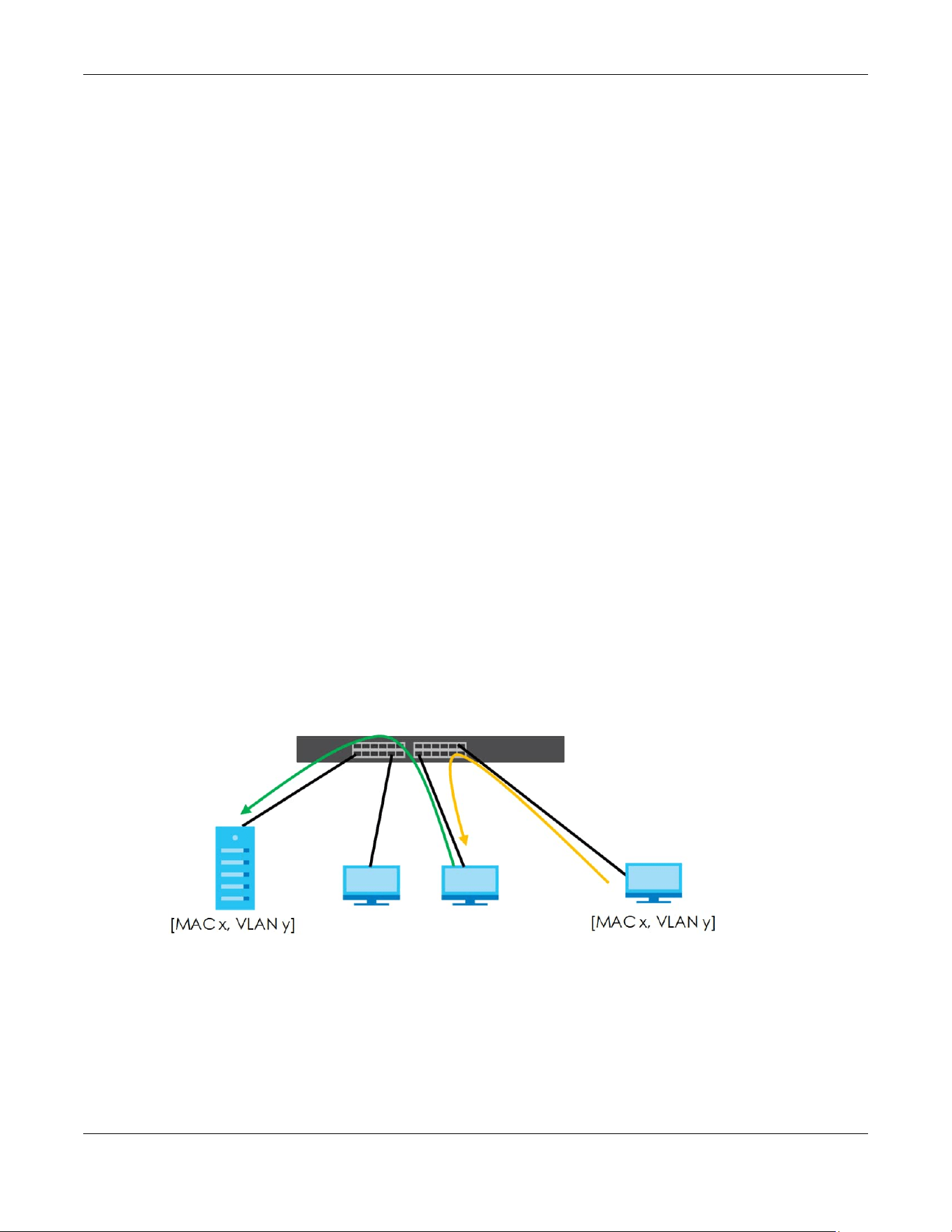
Chapter 44 MAC Pinning
XGS2220 Series User’s Guide
310
CHAPTER 44
MAC Pinning
This chapter shows you how to configure MAC pinning on the Switch.
44.1 MAC Pinning Overview
When the Switch obtains a connected device’s MAC address, it adds an entry in the MAC address
forwarding table and uses the table to determine how to forward frames. In addition to the source MAC
address of a received frame, the Switch also learns the VLAN to which the device belongs and the port
on which the frame is received. If the Switch learns the same MAC address and same VLAN ID on
another port, it updates the MAC address table immediately.
MAC pinning allows you to set a port or multiple ports to have priority over other ports in MAC address
learning. That means when a MAC address (and VLAN ID) is learned on a MAC-pinning-enabled port,
the MAC address will not be learned on any other port until the aging time for the dynamically learned
MAC address in the table expires.
This helps enhance security. For example, when an attacker (A) sends packets to all connected clients
by spoofing the source MAC address of a server (B) connected to one of the Switch’s ports, on which
MAC pinning is enabled, the responses from clients will still be forwarded to the server according to the
Switch’s MAC forwarding table.
44.2 MAC Pinning Configuration
Use this screen to enable MAC pinning on the Switch and on specific ports. Click SWITCHING > MAC
Pinning in the navigation panel to open the following screen.
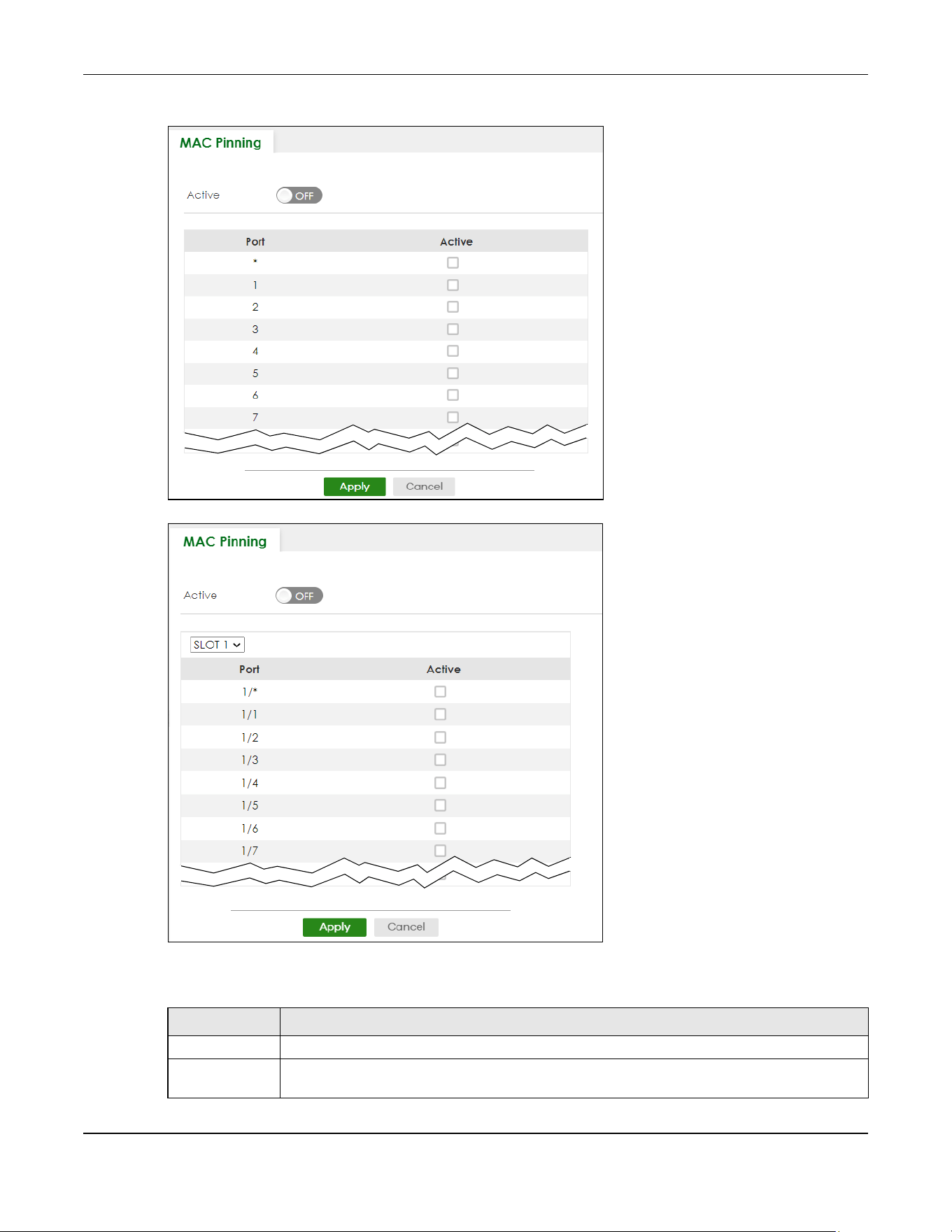
Chapter 44 MAC Pinning
XGS2220 Series User’s Guide
311
Figure 234 SWITCHING > MAC Pinning (Standalone Mode)
Figure 235 SWITCHING > MAC Pinning (Stacking Mode)
The following table describes the labels in this screen.
Table 141 SWITCHING > MAC Pinning
LABEL DESCRIPTION
Active Enable the switch button to turn on the MAC pinning function on the Switch.
SLOT This field appears only in Stacking mode. Click the drop-down list to choose the slot number of
the Switch in a stack.

Chapter 44 MAC Pinning
XGS2220 Series User’s Guide
312
Port This field displays the port number. In Stacking mode, the first number represents the slot ID and
the second is the port number. Please note that the default stacking ports (the last four ports of
your Switch) cannot be configured. They are reserved for stacking only.
* Settings in this row apply to all ports.
Use this row only if you want to make some settings the same for all ports. Use this row first to set
the common settings and then make adjustments on a port-by-port basis.
Note: Changes in this row are copied to all the ports as soon as you make them.
Active Select this check box to enable MAC pinning on this port. The port then has priority over other
ports in MAC address learning.
Clear this check box to disable MAC pinning.
Apply Click Apply to save your changes to the Switch’s run-time memory. The Switch loses these
changes if it is turned off or loses power, so use the Save link on the top navigation panel to save
your changes to the non-volatile memory when you are done configuring.
Cancel Click Cancel to begin configuring this screen afresh.
Table 141 SWITCHING > MAC Pinning (continued)
LABEL DESCRIPTION

Chapter 45 Mirroring
XGS2220 Series User’s Guide
313
CHAPTER 45
Mirroring
45.1 Mirroring Overview
This chapter discusses port mirroring setup screens.
Port mirroring allows you to copy a traffic flow to a monitor port (the port you copy the traffic to) in order
that you can examine the traffic from the monitor port without interference.
45.2 Local Port Mirroring
Click SWITCHING > Mirroring > Mirroring in the navigation panel to display the Mirroring screen. Use this
screen to select a monitor port and specify the traffic flow to be copied to the monitor port.
Figure 236 SWITCHING > Mirroring > Mirroring (Standalone Mode)
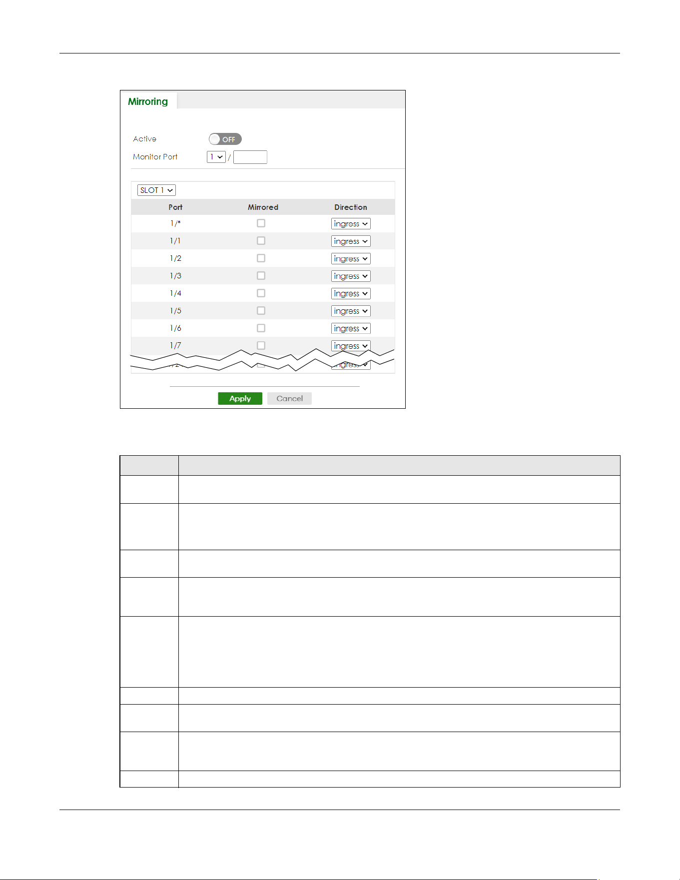
Chapter 45 Mirroring
XGS2220 Series User’s Guide
314
Figure 237 SWITCHING > Mirroring > Mirroring (Stacking Mode)
The following table describes the labels in this screen.
Table 142 SWITCHING > Mirroring > Mirroring
LABEL DESCRIPTION
Active Enable the switch button to activate port mirroring on the Switch. Disable the switch to disable the
feature.
Monitor
Port
The monitor port is the port you copy the traffic to in order to examine it in more detail without
interfering with the traffic flow on the original ports. Type the port number of the monitor port.
In Stacking mode, the first box field is the slot ID and the second field is the port number.
SLOT This field appears only in Stacking mode. Click the drop-down list to choose the slot number of the
Switch in a stack.
Port This field displays the port number. In Stacking mode, the first number represents the slot ID and the
second is the port number. Please note that the default stacking ports (the last four ports of your
Switch) cannot be configured. They are reserved for stacking only.
* Settings in this row apply to all ports.
Use this row only if you want to make some settings the same for all ports. Use this row first to set the
common settings and then make adjustments on a port-by-port basis.
Note: Changes in this row are copied to all the ports as soon as you make them.
Mirrored Select this option to mirror the traffic on a port.
Direction Specify the direction of the traffic to mirror by selecting from the drop-down list box. Choices are
Egress (outgoing), Ingress (incoming) and Both.
Apply Click Apply to save your changes to the Switch’s run-time memory. The Switch loses these changes if
it is turned off or loses power, so use the Save link on the top navigation panel to save your changes
to the non-volatile memory when you are done configuring.
Cancel Click Cancel to reset the fields.

Chapter 46 Multicast
XGS2220 Series User’s Guide
315
CHAPTER 46
Multicast
46.1 Multicast Overview
This chapter shows you how to configure various multicast features.
Traditionally, IP packets are transmitted in one of either two ways
– Unicast (one sender to one recipient)
or Broadcast (one sender to everybody on the network). Multicast delivers IP packets to just a group of
hosts on the network.
IGMP (Internet Group Management Protocol) is a network-layer protocol used to establish membership
in a multicast group
– it is not used to carry user data. Refer to RFC 1112, RFC 2236 and RFC 3376 for
information on IGMP versions 1, 2 and 3 respectively.
The Multicast Listener Discovery (MLD) protocol (defined in RFC 2710) is derived from IPv4's Internet
Group Management Protocol version 2 (IGMPv2). MLD uses ICMPv6 message types, rather than IGMP
message types. MLDv1 is similar to IGMPv2 and MLDv2 is similar to IGMPv3. MLD allows an IPv6 switch or
router to discover the presence of MLD listeners who wish to receive multicast packets and the IP
addresses of multicast groups the hosts want to join on its network.
MLD snooping and MLD proxy are analogous to IGMP snooping and IGMP proxy in IPv4. MLD filtering
controls which multicast groups a port can join.
• Use the IPv4 Multicast Status screen (Section 46.2 on page 319) to view IPv4 multicast group
information.
• Use the IGMP Snooping screen (Section 46.3 on page 320) to enable IGMP snooping to forward group
multicast traffic only to ports that are members of that group.
• Use the IGMP Snooping VLAN screen (Section 46.4 on page 324) to perform IGMP snooping on VLANs.
• Use the IGMP Filtering Profile (Section 46.5 on page 326) to specify a range of multicast groups that
clients connected to the Switch are able to join.
46.1.1 What You Can Do – IPv6 Multicast
• Use the IPv6 Multicast Status screen (Section 46.6 on page 328) to view IPv6 multicast group
information.
• Use the MLD Snooping-proxy screen (Section 46.7 on page 329) to enable the upstream port to report
group changes to a connected multicast router and forward MLD messages to other upstream ports.
• Use the MLD Snooping-proxy VLAN screen (Section 46.8 on page 329) to enable and configure MLD
snooping-proxy settings on the VLANs you specified.
• Use the MLD Snooping-proxy Port Role Setting screen (Section 46.9 on page 332) to assign MLD
snooping-proxy port roles and configure Leave settings for each port.
• Use the MLD Snooping-proxy Filtering screen (Section 46.10 on page 334) to enable and configure
MLD snooping-proxy filtering.

Chapter 46 Multicast
XGS2220 Series User’s Guide
316
• Use the MLD Snooping-proxy Filtering Profile screen (Section 46.11 on page 336) to create/edit MLD
snooping-proxy filtering profiles.
46.1.2 What You Can Do – MVR
• Use the MVR screen (Section 46.12 on page 338) to create multicast VLANs and select the receiver
ports and a source port for each multicast VLAN.
• Use the Group Setup screen (Section 46.12 on page 338) to configure MVR IP multicast group
addresses.
46.1.3 What You Need to Know
Read on for concepts on Multicasting that can help you configure the screens in this chapter.
IP Multicast Addresses
In IPv4, a multicast address allows a device to send packets to a specific group of hosts (multicast
group) in a different subnetwork. A multicast IP address represents a traffic receiving group, not
individual receiving devices. IP addresses in the Class D range (224.0.0.0 to 239.255.255.255) are used for
IP multicasting. Certain IP multicast numbers are reserved by IANA for special purposes (see the IANA
website for more information).
In IPv6, multicast addresses provide the same functionality as IPv4 broadcast addresses. Broadcasting is
not supported in IPv6. A multicast address allows a host to send packets to all hosts in a multicast group.
Multicast scope allows you to determine the size of the multicast group. A multicast address has a
predefined prefix of ff00::/8.
IGMP Filtering
With the IGMP filtering feature, you can control which IGMP groups a subscriber on a port can join. This
allows you to control the distribution of multicast services (such as content information distribution)
based on service plans and types of subscription.
You can set the Switch to filter the multicast group join reports on a per-port basis by configuring an
IGMP filtering profile and associating the profile to a port.
IGMP Snooping
A Switch can passively snoop on IGMP packets transferred between IP multicast routers or switches and
IP multicast hosts to learn the IP multicast group membership. It checks IGMP packets passing through it,
picks out the group registration information, and configures multicasting accordingly. IGMP snooping
allows the Switch to learn multicast groups without you having to manually configure them.
The Switch forwards multicast traffic destined for multicast groups (that it has learned from IGMP
snooping or that you have manually configured) to ports that are members of that group. IGMP
snooping generates no additional network traffic, allowing you to significantly reduce multicast traffic
passing through your Switch.

Chapter 46 Multicast
XGS2220 Series User’s Guide
317
IGMP Snooping and VLANs
The Switch can perform IGMP snooping on up to 16 VLANs. You can configure the Switch to
automatically learn multicast group membership of any VLANs. The Switch then performs IGMP
snooping on the first 16 VLANs that send IGMP packets. This is referred to as auto mode. Alternatively,
you can specify the VLANs that IGMP snooping should be performed on. This is referred to as fixed
mode. In fixed mode the Switch does not learn multicast group membership of any VLANs other than
those explicitly added as an IGMP snooping VLAN.
MLD Snooping-proxy
MLD snooping-proxy is a Zyxel-proprietary feature. IPv6 MLD proxy allows only one upstream interface on
a switch, while MLD snooping-proxy supports more than one upstream port on a switch. The upstream
port in MLD snooping-proxy can report group changes to a connected multicast router and forward
MLD messages to other upstream ports. This helps especially when you want to have a network that uses
STP to provide backup links between switches and also performs MLD snooping and proxy functions.
MLD snooping-proxy, like MLD proxy, can minimize MLD control messages and allow better network
performance.
In MLD snooping-proxy, if one upstream port is learned through snooping, all other upstream ports on the
same device will be added to the same group. If one upstream port requests to leave a group, all other
upstream ports on the same device will also be removed from the group.
In the following MLD snooping-proxy example, all connected upstream ports (1
– 7) are treated as one
interface. The connection between ports 8 and 9 is blocked by STP to break the loop. If there is one
query from a router (X) or MLD Done or Report message from any upstream port, it will be broadcast to
all connected upstream ports.
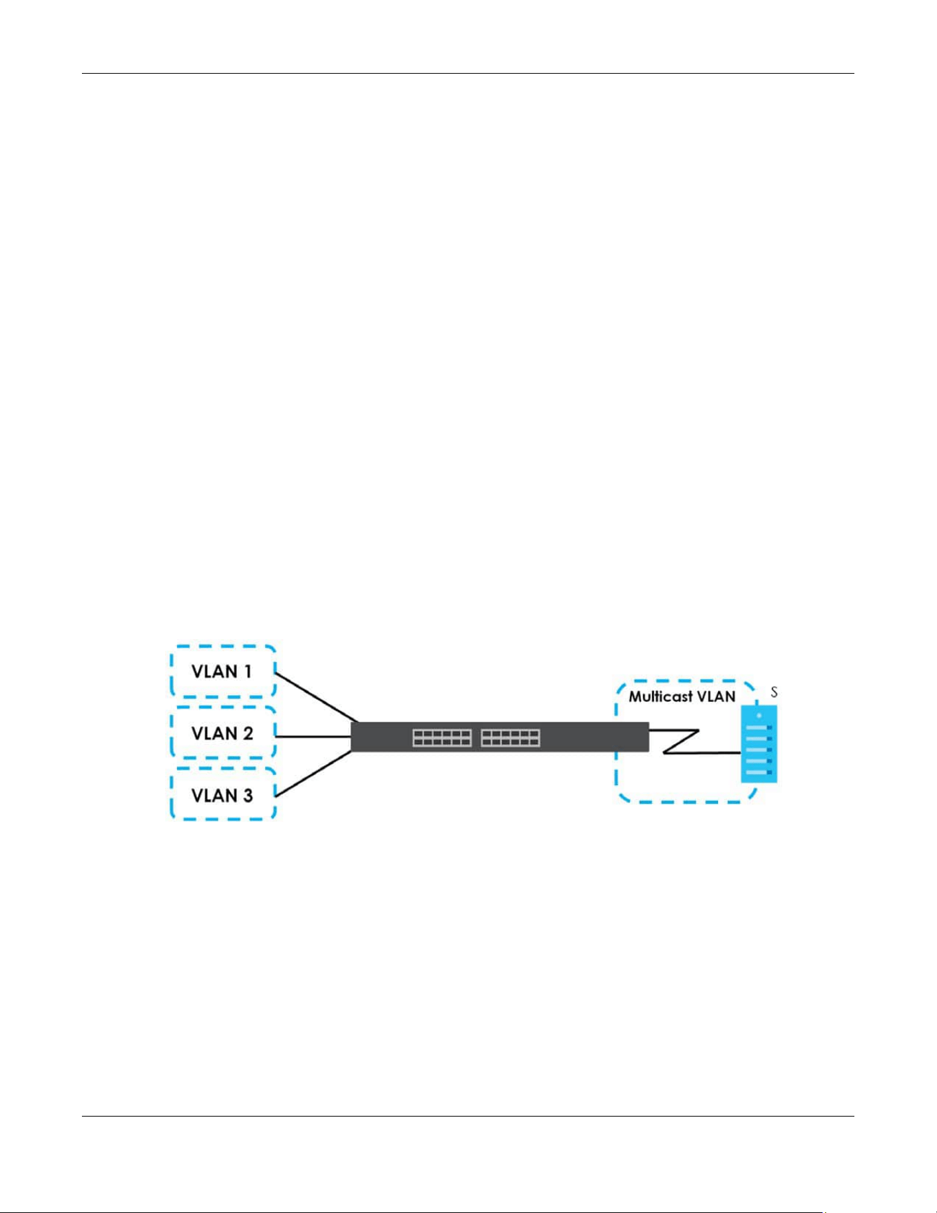
Chapter 46 Multicast
XGS2220 Series User’s Guide
318
MLD Messages
A multicast router or switch periodically sends general queries to MLD hosts to update the multicast
forwarding table. When an MLD host wants to join a multicast group, it sends an MLD Report message
for that address.
An MLD Done message is similar to an IGMP Leave message. When an MLD host wants to leave a
multicast group, it can send a Done message to the router or switch. If the leave mode is not set to
Immediate, the router or switch sends a group-specific query to the port on which the Done message is
received to determine if other devices connected to this port should remain in the group.
MVR Overview
Multicast VLAN Registration (MVR) is designed for applications (such as Media-on-Demand (MoD)) that
use multicast traffic across an Ethernet ring-based service provider network.
MVR allows one single multicast VLAN to be shared among different subscriber VLANs on the network.
While isolated in different subscriber VLANs, connected devices can subscribe to and unsubscribe from
the multicast stream in the multicast VLAN. This improves bandwidth utilization with reduced multicast
traffic in the subscriber VLANs and simplifies multicast group management.
MVR only responds to IGMP join and leave control messages from multicast groups that are configured
under MVR. Join and leave reports from other multicast groups are managed by IGMP snooping.
The following figure shows a network example. The subscriber VLAN (1, 2 and 3) information is hidden
from the streaming media server, S. In addition, the multicast VLAN information is only visible to the
Switch and S.
Figure 238 MVR Network Example
Types of MVR Ports
In MVR, a source port is a port on the Switch that can send and receive multicast traffic in a multicast
VLAN while a receiver port can only receive multicast traffic. Once configured, the Switch maintains a
forwarding table that matches the multicast stream to the associated multicast group.
MVR Modes
You can set your Switch to operate in either dynamic or compatible mode.
In dynamic mode, the Switch sends IGMP leave and join reports to the other multicast devices (such as
multicast routers or servers) in the multicast VLAN. This allows the multicast devices to update the
multicast forwarding table to forward or not forward multicast traffic to the receiver ports.
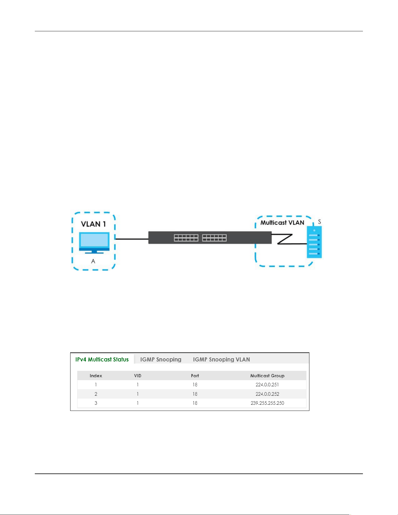
Chapter 46 Multicast
XGS2220 Series User’s Guide
319
In compatible mode, the Switch does not send any IGMP reports. In this case, you must manually
configure the forwarding settings on the multicast devices in the multicast VLAN.
How MVR Works
The following figure shows a multicast television example where a subscriber device (such as a
computer) in VLAN 1 receives multicast traffic from the streaming media server, S, through the Switch.
Multiple subscriber devices can connect through a port configured as the receiver on the Switch.
When the subscriber selects a television channel, computer A sends an IGMP report to the Switch to join
the appropriate multicast group. If the IGMP report matches one of the configured MVR multicast group
addresses on the Switch, an entry is created in the forwarding table on the Switch. This maps the
subscriber VLAN to the list of forwarding destinations for the specified multicast traffic.
When the subscriber changes the channel or turns off the computer, an IGMP leave message is sent to
the Switch to leave the multicast group. The Switch sends a query to VLAN 1 on the receiver port (in this
case, an uplink port on the Switch). If there is another subscriber device connected to this port in the
same subscriber VLAN, the receiving port will still be on the list of forwarding destination for the multicast
traffic. Otherwise, the Switch removes the receiver port from the forwarding table.
Figure 239 MVR Multicast Television Example
46.2 IPv4 Multicast Status
Click SWITCHING > Multicast > IPv4 Multicast > IPv4 Multicast Status to display the screen as shown. This
screen shows the IPv4 multicast group information. See Section 46.1 on page 315 for more information
on multicasting.
Figure 240 SWITCHING > Multicast > IPv4 Multicast > IPv4 Multicast Status
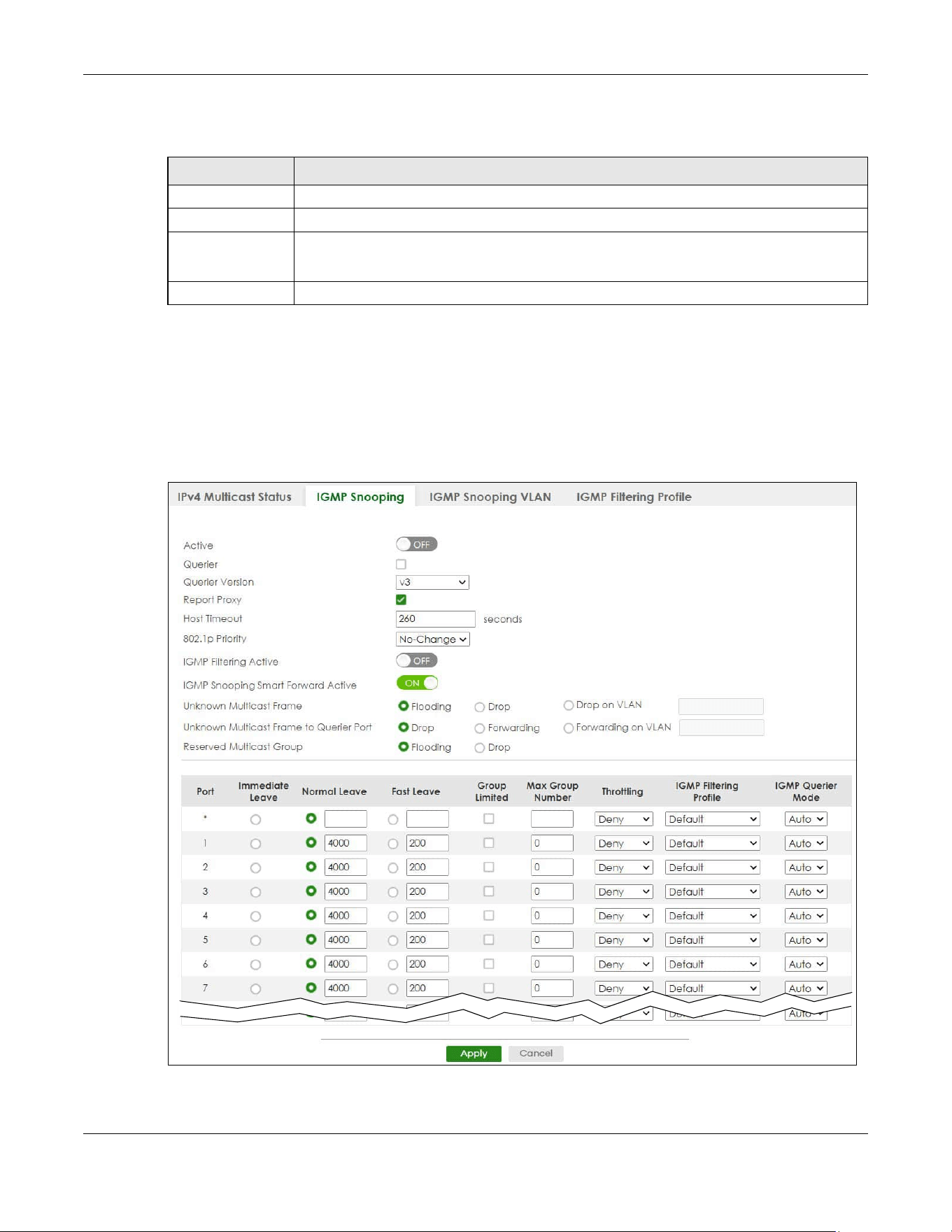
Chapter 46 Multicast
XGS2220 Series User’s Guide
320
The following table describes the labels in this screen.
46.3 IGMP Snooping
Click SWITCHING > Multicast > IPv4 Multicast > IGMP Snooping to display the screen as shown. See
Section 46.1 on page 315 for more information on multicasting.
Figure 241 SWITCHING > Multicast > IPv4 Multicast > IGMP Snooping (Standalone Mode)
Table 143 SWITCHING > Multicast > IPv4 Multicast > IPv4 Multicast Status
LABEL DESCRIPTION
Index This is the index number of the entry.
VID This field displays the multicast VLAN ID.
Port This field displays the port number that belongs to the multicast group.
In Stacking mode, the first number represents the slot and the second is the port number.
Multicast Group This field displays IP multicast group addresses.
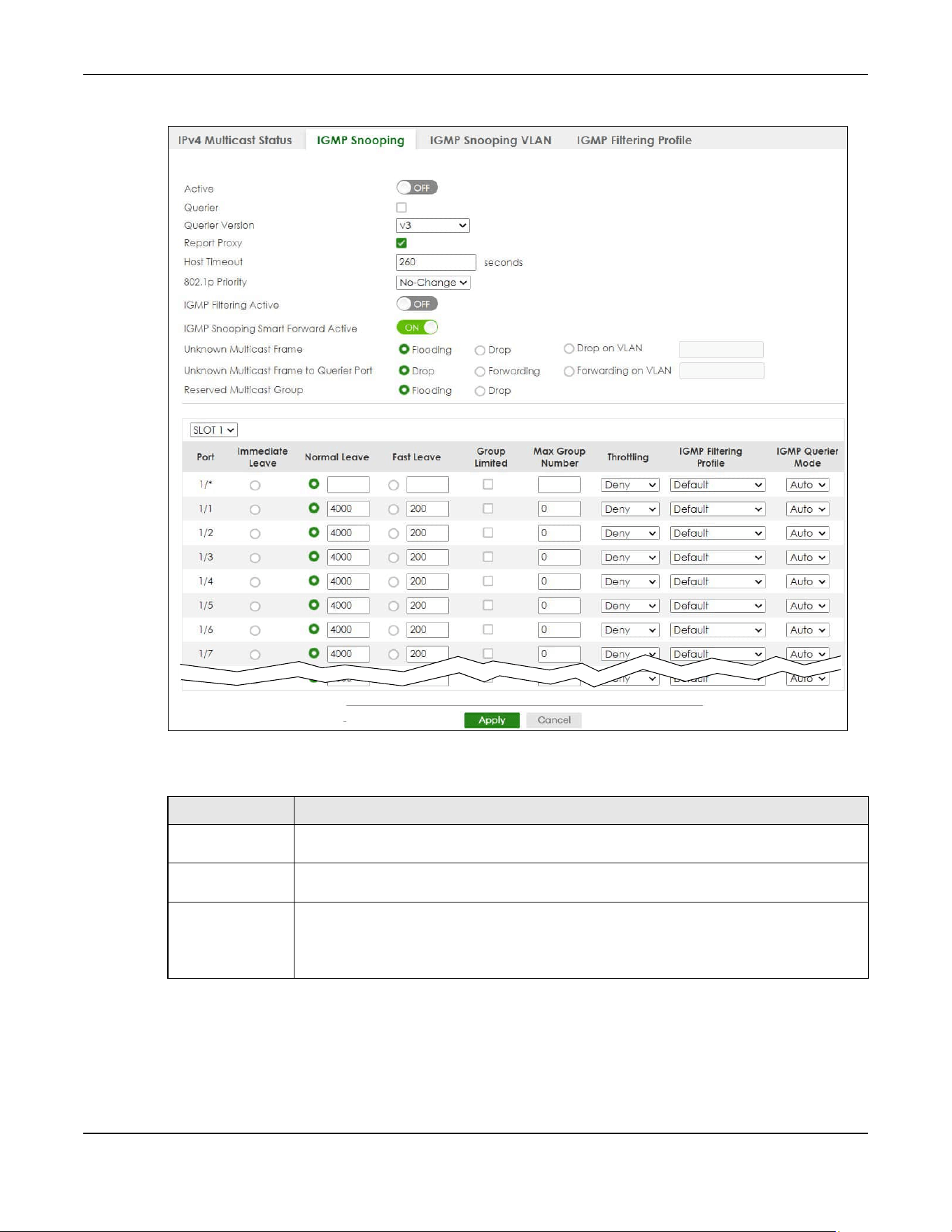
Chapter 46 Multicast
XGS2220 Series User’s Guide
321
Figure 242 SWITCHING > Multicast > IPv4 Multicast > IGMP Snooping (Stacking Mode)
The following table describes the labels in this screen.
Table 144 SWITCHING > Multicast > IPv4 Multicast > IGMP Snooping
LABEL DESCRIPTION
Active Enable the switch button to enable IGMP Snooping to forward group multicast traffic only to
ports that are members of that group.
Querier Select this to allow the Switch to send IGMP General Query messages to the VLANs with the
multicast hosts attached.
Querier Version IGMP snooping query works only when both host and Switch support the same IGMP version.
Select v2 to allow the Switch to send IGMPv2 queries only.
Select v3 to allow the Switch to send IGMPv3 queries only.
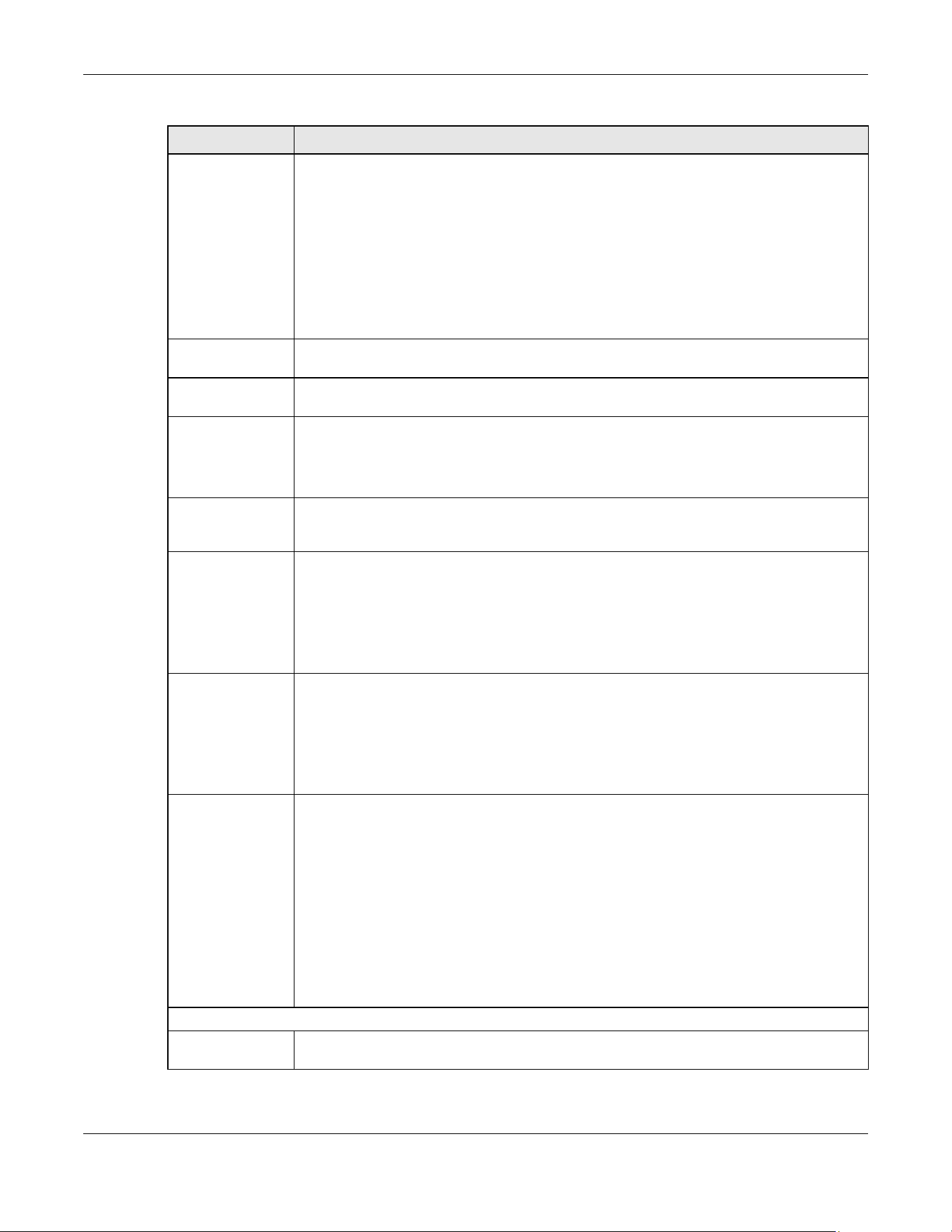
Chapter 46 Multicast
XGS2220 Series User’s Guide
322
Report Proxy Select this to allow the Switch to act as the IGMP report proxy and leave proxy. It will report
group changes to a connected multicast router.
The Switch not only checks IGMP packets between multicast routers or switches and multicast
hosts to learn the multicast group membership, but also replaces the source MAC address in
an IGMP v1/v2 report with its own MAC address before forwarding to the multicast router or
switch. When the Switch receives more than one IGMP v1/v2 join report that requests to join
the same multicast group, it only sends a new join report with its MAC address. This helps
reduce the number of multicast join reports passed to the multicast router or switch.
The Switch sends a leave message with its MAC address to the multicast router or switch only
when it receives the leave message from the last host in a multicast group.
Host Timeout Specify the time (from 1 to 16711450) in seconds that elapses before the Switch removes an
IGMP group membership entry if it does not receive report messages from the port.
802.1p Priority Select a priority level (0 – 7) to which the Switch changes the priority in outgoing IGMP control
packets. Otherwise, select No-Change to not replace the priority.
IGMP Filtering
Active
Enable the switch button to enable IGMP filtering to control which IGMP groups a subscriber
on a port can join.
If you enable IGMP filtering, you must create and assign IGMP filtering profiles for the ports that
you want to allow to join multicast groups.
IGMP Snooping
Smart Forward
Active
Enable the switch button to enable sending of multicast frame to querier port and IGMP
subscriber groups. Otherwise, the querier port forwards the frames only when it receives a join
report and it belongs to the IGMP group.
Unknown Multicast
Frame
Specify the action to perform when the Switch receives an unknown multicast frame.
•Select Flooding to send the frames to all ports.
•Select Drop to discard the frames.
•Select Drop on VLAN and enter the VLAN ID numbers to discard the frames on the
specified VLANs. Use a dash to specify consecutive VLANs and a comma (no spaces) to
specify non-consecutive VLANs. For example, 51–53 includes 51, 52 and 53, but 51,53 does
not include 52.
Unknown Multicast
Frame to Querier
Port
Specify the action to perform when Unknown Multicast Frame is set to Drop.
•Select Drop to discard the frames.
•Select Forwarding to send the frames to all querier ports.
•Select Forwarding on VLAN and enter the VLAN ID numbers to send the frames to the ports
which are used as an IGMP query port on the specified VLANs. Use a dash to specify
consecutive VLANs and a comma (no spaces) to specify non-consecutive VLANs. For
example, 51–53 includes 51, 52 and 53, but 51,53 does not include 52.
Reserved Multicast
Group
The IP address range of 224.0.0.0 to 224.0.0.255 are reserved for multicasting on the local
network only. For example, 224.0.0.1 is for all hosts on a local network segment and 224.0.0.9 is
used to send RIP routing information to all RIP v2 routers on the same network segment. A
multicast router will not forward a packet with the destination IP address within this range to
other networks. See the IANA web site for more information.
The layer-2 multicast MAC addresses used by Cisco layer-2 protocols, 01:00:0C:CC:CC:CC
and 01:00:0C:CC:CC:CD, are also included in this group.
Specify the action to perform when the Switch receives a frame with a reserved multicast
address.
•Select Flooding to send the frames to all ports.
•Select Drop to discard the frames.
Use this section to configure IGMP Snooping on each port.
SLOT This field appears only in Stacking mode. Click the drop-down list to choose the slot number of
the Switch in a stack.
Table 144 SWITCHING > Multicast > IPv4 Multicast > IGMP Snooping (continued)
LABEL DESCRIPTION

Chapter 46 Multicast
XGS2220 Series User’s Guide
323
Port This field displays the port number. In Stacking mode, the first number represents the slot ID
and the second is the port number. Please note that the default stacking ports (the last four
ports of your Switch) cannot be configured. They are reserved for stacking only.
* Settings in this row apply to all ports.
Use this row only if you want to make some settings the same for all ports. Use this row first to set
the common settings and then make adjustments on a port-by-port basis.
Changes in this row are copied to all the ports as soon as you make them.
Immediate Leave Select this to set the Switch to remove this port from the multicast tree when an IGMP version 2
leave message is received on this port.
Select this option if there is only one host connected to this port.
Normal Leave Enter an IGMP normal leave timeout value (from 200 to 6348800) in miliseconds. Select this
option to have the Switch use this timeout to update the forwarding table for the port.
In normal leave mode, when the Switch receives an IGMP leave message from a host on a
port, it forwards the message to the multicast router. The multicast router then sends out an
IGMP Group-Specific Query (GSQ) message to determine whether other hosts connected to
the port should remain in the specific multicast group. The Switch forwards the query message
to all hosts connected to the port and waits for IGMP reports from hosts to update the
forwarding table.
This defines how many seconds the Switch waits for an IGMP report before removing an IGMP
snooping membership entry when an IGMP leave message is received on this port from a
host.
Fast Leave Enter an IGMP fast leave timeout value (from 200 to 6348800) in miliseconds. Select this option
to have the Switch use this timeout to update the forwarding table for the port.
In fast leave mode, right after receiving an IGMP leave message from a host on a port, the
Switch itself sends out an IGMP Group-Specific Query (GSQ) message to determine whether
other hosts connected to the port should remain in the specific multicast group. This helps
speed up the leave process.
This defines how many seconds the Switch waits for an IGMP report before removing an IGMP
snooping membership entry when an IGMP leave message is received on this port from a
host.
Group Limited Select this option to limit the number of multicast groups this port is allowed to join.
Max Group
Number
Enter the number of multicast groups this port is allowed to join. Once a port is registered in the
specified number of multicast groups, any new IGMP join report frames is dropped on this
port.
Throttling IGMP throttling controls how the Switch deals with the IGMP reports when the maximum
number of the IGMP groups a port can join is reached.
Select Deny to drop any new IGMP join report received on this port until an existing multicast
forwarding table entry is aged out.
Select Replace to replace an existing entry in the multicast forwarding table with the new
IGMP reports received on this port.
IGMP Filtering
Profile
Select the name of the IGMP filtering profile to use for this port. Otherwise, select Default to
prohibit the port from joining any multicast group.
You can create IGMP filtering profiles in the SWITCHING > Multicast > IPv4 Multicast > IGMP
Filtering Profile screen.
Table 144 SWITCHING > Multicast > IPv4 Multicast > IGMP Snooping (continued)
LABEL DESCRIPTION
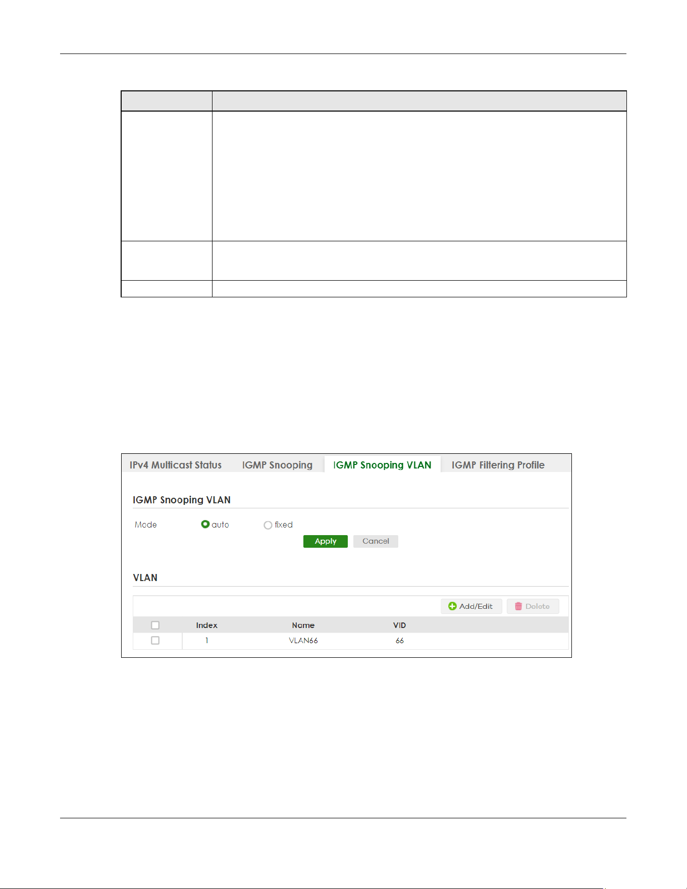
Chapter 46 Multicast
XGS2220 Series User’s Guide
324
46.4 IGMP Snooping VLAN
Click SWITCHING > Multicast > IPv4 Multicast > IGMP Snooping VLAN to display the screen as shown. See
IGMP Snooping and VLANs on page 317 for more information on IGMP Snooping VLAN.
Note: You can perform IGMP snooping on up to 16 VLANs.
Figure 243 SWITCHING > Multicast > IPv4 Multicast > IGMP Snooping VLAN
IGMP Querier
Mode
The Switch treats an IGMP query port as being connected to an IGMP multicast router (or
server). The Switch forwards IGMP join or leave packets to an IGMP query port.
Select Auto to have the Switch use the port as an IGMP query port if the port receives IGMP
query packets.
Select Fixed to have the Switch always use the port as an IGMP query port. Select this when
you connect an IGMP multicast server to the port.
Select Edge to stop the Switch from using the port as an IGMP query port. The Switch will not
keep any record of an IGMP router being connected to this port. The Switch does not forward
IGMP join or leave packets to this port.
Apply Click Apply to save your changes to the Switch’s run-time memory. The Switch loses these
changes if it is turned off or loses power, so use the Save link on the top navigation panel to
save your changes to the non-volatile memory when you are done configuring.
Cancel Click Cancel to begin configuring this screen afresh.
Table 144 SWITCHING > Multicast > IPv4 Multicast > IGMP Snooping (continued)
LABEL DESCRIPTION

Chapter 46 Multicast
XGS2220 Series User’s Guide
325
The following table describes the labels in this screen.
46.4.1 Add/Edit IGMP Snooping VLANs
This screen allows you to add an IGMP snooping VLAN or edit an existing one.
To access this screen, click the Add/Edit button or select an entry from the list and click the Add/Edit
button.
Figure 244 SWITCHING > Multicast > IPv4 Multicast > IGMP Snooping VLAN > Add/Edit
Table 145 SWITCHING > Multicast > IPv4 Multicast > IGMP Snooping VLAN
LABEL DESCRIPTION
IGMP Snooping VLAN
Mode Select auto to have the Switch learn multicast group membership information of any VLANs
automatically.
Select fixed to have the Switch only learn multicast group membership information of the
VLANs that you specify below.
In either auto or fixed mode, the Switch can learn up to 16 VLANs (including up to five VLANs
you configured in the MVR screen). For example, if you have configured one multicast VLAN
in the SWITCHING > Multicast > MVR screen, you can only specify up to 15 VLANs in this screen.
The Switch drops any IGMP control messages which do not belong to these 16 VLANs.
You must also enable IGMP snooping in the SWITCHING > Multicast > IPv4 Multicast > IGMP
Snooping screen first.
Apply Click Apply to save your changes to the Switch’s run-time memory. The Switch loses these
changes if it is turned off or loses power, so use the Save link on the top navigation panel to
save your changes to the non-volatile memory when you are done configuring.
Cancel Click Cancel to begin configuring this screen afresh.
VLAN
Use this section of the screen to add VLANs on which the Switch is to perform IGMP snooping.
Index This is the index number of the IGMP snooping VLAN entry in the table.
Name This field displays the descriptive name for this VLAN group.
VID This field displays the ID number of the VLAN group.
Select an entry’s check box to select a specific entry. Otherwise, select the check box in the
table heading row to select all entries.
Add/Edit Click Add/Edit to create a new entry or edit a selected one.
Delete Click Delete to remove the selected entries.
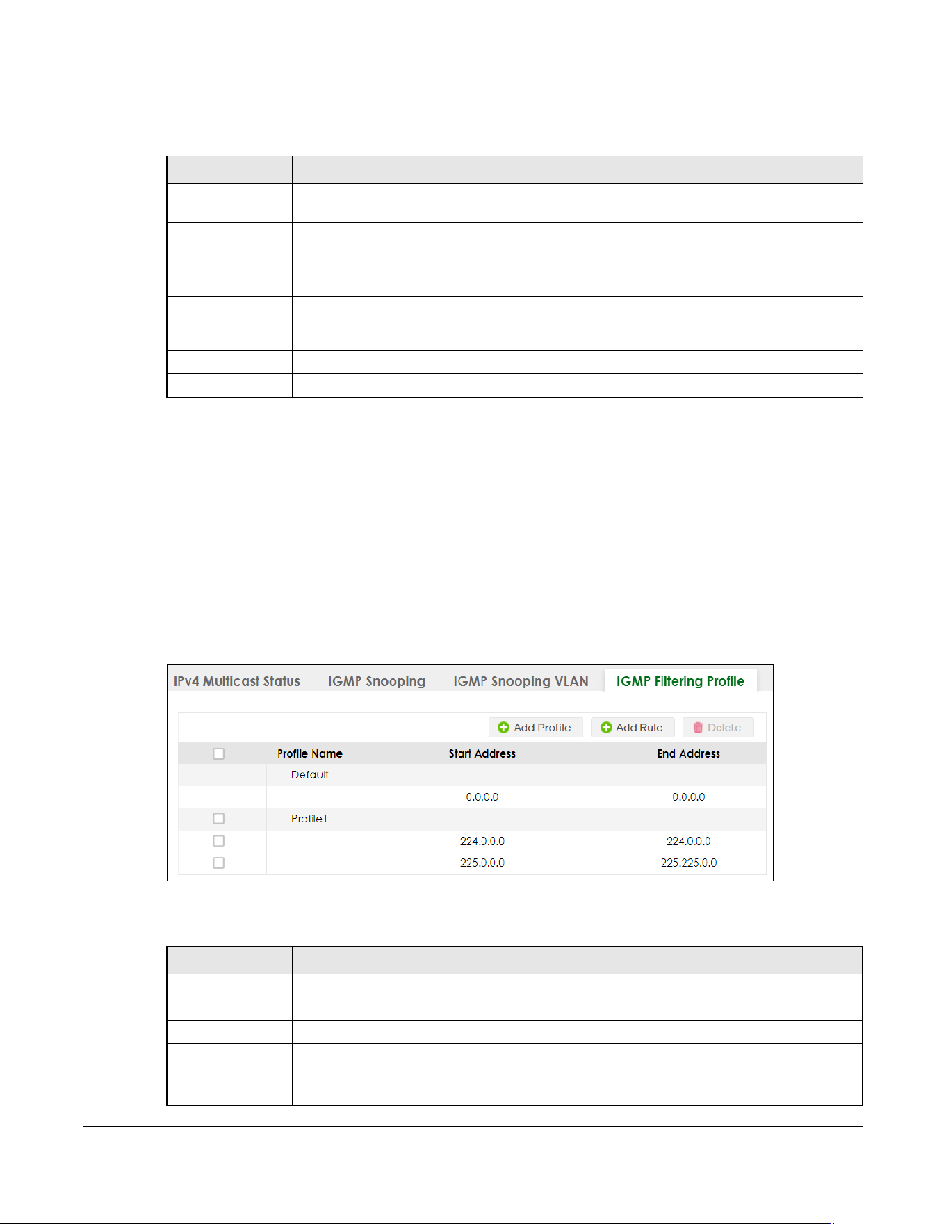
Chapter 46 Multicast
XGS2220 Series User’s Guide
326
The following table describes the labels in this screen.
46.5 IGMP Filtering Profile
An IGMP filtering profile specifies a range of multicast groups that clients connected to the Switch are
able to join. A profile contains a range of multicast IP addresses which you want clients to be able to
join. Profiles are assigned to ports (in the SWITCHING > Multicast > IPv4 Multicast > IGMP Snooping
screen). Clients connected to those ports are then able to join the multicast groups specified in the
profile. Each port can be assigned a single profile. A profile can be assigned to multiple ports.
Click SWITCHING > Multicast > IPv4 Multicast > IGMP Filtering Profile link to display the screen as shown.
Figure 245 SWITCHING > Multicast > IPv4 Multicast > IGMP Filtering Profile
The following table describes the labels in this screen.
Table 146 SWITCHING > Multicast > IPv4 Multicast > IGMP Snooping VLAN > Add/Edit
LABEL DESCRIPTION
Name Enter the descriptive name of the VLAN for identification purposes. You can enter up to 32
printable ASCII characters except [ ? ], [ | ], [ ' ], [ " ] or [ , ].
VID Enter the ID of a static VLAN; the valid range is between 1 and 4094.
Note: You cannot configure the same VLAN ID as in the SWITCHING > Multicast >
MVR screen.
Apply Click Apply to save your changes to the Switch’s run-time memory. The Switch loses these
changes if it is turned off or loses power, so use the Save link on the top navigation panel to
save your changes to the non-volatile memory when you are done configuring.
Clear Click Clear to clear the fields to the factory defaults.
Cancel Click Cancel to not save the configuration you make and return to the last screen.
Table 147 SWITCHING > Multicast > IPv4 Multicast > IGMP Filtering Profile
LABEL DESCRIPTION
Profile Name This field displays the descriptive name of the profile.
Start Address This field displays the start of the multicast address range.
End Address This field displays the end of the multicast address range.
Select an entry’s check box to select a specific entry. Otherwise, select the check box in the
table heading row to select all entries.
Add Profile Click this to add a new IGMP filtering profile.
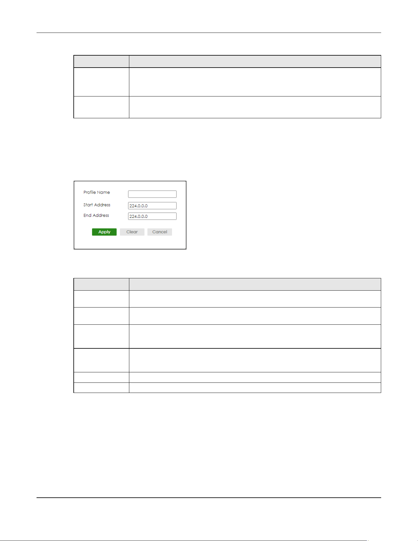
Chapter 46 Multicast
XGS2220 Series User’s Guide
327
46.5.1 Add IGMP Filtering Profile
To access this screen, click the Add Profile button in the SWITCHING > Multicast > IPv4 Multicast > IGMP
Filtering Profile screen.
Figure 246 SWITCHING > Multicast > IPv4 Multicast > IGMP Filtering Profile > Add Profile
The following table describes the labels in this screen.
46.5.2 Add IGMP Filtering Rule
Click Add Rule in the SWITCHING > Multicast > IPv4 Multicast > IGMP Filtering Profile screen to access this
screen.
Add Rule Click Add Rule to add a new rule and specify the profile it belongs to in the Add Rule screen.
You can also select a profile entry and click Add Rule to add an additional rule for the
selected profile.
Delete Select a profile and click Delete to remove the selected profile and the accompanying rules.
Select a rule from a profile and click Delete to remove the selected rule.
Table 147 SWITCHING > Multicast > IPv4 Multicast > IGMP Filtering Profile (continued)
LABEL DESCRIPTION
Table 148 SWITCHING > Multicast > IPv4 Multicast > IGMP Filtering Profile > Add Profile
LABEL DESCRIPTION
Profile Name Enter a descriptive name for the profile for identification purposes. You can enter up to 32
printable ASCII characters except [ ? ], [ | ], [ ' ], [ " ] or [ , ].
Start Address Enter the starting multicast IP address for a range of multicast IP addresses that you want to
belong to the IGMP filter profile.
End Address Enter the ending multicast IP address for a range of IP addresses that you want to belong to
the IGMP filter profile. If you want to add a single multicast IP address, enter it in both the Start
Address and End Address fields.
Apply Click Apply to save your changes to the Switch’s run-time memory. The Switch loses these
changes if it is turned off or loses power, so use the Save link on the top navigation panel to
save your changes to the non-volatile memory when you are done configuring.
Clear Click Clear to clear the fields to the factory defaults.
Cancel Click Cancel to not save the configuration you make and return to the last screen.

Chapter 46 Multicast
XGS2220 Series User’s Guide
328
Figure 247 SWITCHING > Multicast > IPv4 Multicast > IGMP Filtering Profile > Add Rule
The following table describes the labels in this screen.
46.6 IPv6 Multicast Status
Click SWITCHING > Multicast > IPv6 Multicast > IPv6 Multicast Status to display the screen as shown. This
screen shows the IPv6 multicast group information. See Section 46.1 on page 315 for more information
on multicasting.
Figure 248 SWITCHING > Multicast > IPv6 Multicast > IPv6 Multicast Status
The following table describes the fields in the above screen.
Table 149 SWITCHING > Multicast > IPv4 Multicast > IGMP Filtering Profile > Add Rule
LABEL DESCRIPTION
Profile Name Select a profile from the drop-down list to add a additional rule for the existing profile.
Start Address Enter the starting multicast IP address for a range of multicast IP addresses that you want to
belong to the IGMP filter profile.
End Address Enter the ending multicast IP address for a range of IP addresses that you want to belong to
the IGMP filter profile. If you want to add a single multicast IP address, enter it in both the Start
Address and End Address fields.
Apply Click Apply to save your changes to the Switch’s run-time memory. The Switch loses these
changes if it is turned off or loses power, so use the Save link on the top navigation panel to
save your changes to the non-volatile memory when you are done configuring.
Clear Click Clear to clear the fields to the factory defaults.
Cancel Click Cancel to not save the configuration you make and return to the last screen.
Table 150 SWITCHING > Multicast > IPv6 Multicast > IPv6 Multicast Status
LABEL DESCRIPTION
Index This is the index number of the entry.
VID This field displays the multicast VLAN ID.
Port This field displays the port number that belongs to the multicast group. In Stacking mode,
the first number represents the slot and the second is the port number.

Chapter 46 Multicast
XGS2220 Series User’s Guide
329
46.7 MLD Snooping-proxy
Click SWITCHING > Multicast > IPv6 Multicast > MLD Snooping-proxy to display the screen as shown. See
Section 46.1 on page 315 for more information on multicasting.
Figure 249 SWITCHING > Multicast > IPv6 Multicast > MLD Snooping-proxy
The following table describes the fields in the above screen.
46.8 MLD Snooping-proxy VLAN
Click SWITCHING > Multicast > IPv6 Multicast > VLAN screen to display the screen as shown. See Section
46.1 on page 315 for more information on multicasting.
Multicast Group This field displays IP multicast group addresses.
Group Timeout This field displays the time (in seconds) that elapses before the Switch removes a MLD group
membership entry if it does not receive report messages from the port.
Table 150 SWITCHING > Multicast > IPv6 Multicast > IPv6 Multicast Status (continued)
LABEL DESCRIPTION
Table 151 SWITCHING > Multicast > IPv6 Multicast > MLD Snooping-proxy
LABEL DESCRIPTION
MLD Snooping-proxy
Use these settings to configure MLD snooping-proxy.
Active Enable the switch button to enable MLD snooping-proxy on the Switch to minimize MLD
control messages and allow better network performance.
802.1p Priority Select a priority level (0 – 7) to which the Switch changes the priority in outgoing MLD
messages.
Apply Click Apply to save your changes to the Switch’s run-time memory. The Switch loses these
changes if it is turned off or loses power, so use the Save link on the top navigation panel
to save your changes to the non-volatile memory when you are done configuring.
Cancel Click Cancel to begin configuring this screen afresh.

Chapter 46 Multicast
XGS2220 Series User’s Guide
330
Figure 250 SWITCHING > Multicast > IPv6 Multicast > VLAN: MLD Snooping-proxy VLAN
The following table describes the fields in the above screen.
46.8.1 Add/Edit MLD Snooping-proxy VLAN
The screen allows you to enable and configure MLD Snooping-proxy settings on a VLAN you specified.
Click Add/Edit in the SWITCHING > Multicast > IPv6 Multicast > VLAN screen to display this screen.
Figure 251 SWITCHING > Multicast > IPv6 Multicast > VLAN > Add/Edit
Table 152 SWITCHING > Multicast > IPv6 Multicast > VLAN: MLD Snooping-proxy VLAN
LABEL DESCRIPTION
MLD Snooping-proxy VLAN
Index This is the index number of the MLD snooping-proxy VLAN entry in the table.
VID This field displays the ID number of the VLAN group.
Select an entry’s check box to select a specific entry. Otherwise, select the check box in
the table heading row to select all entries.
Add/Edit Click Add/Edit to add a new entry or edit a selected one.
Delete Click Delete to remove the selected entry.
Chapter 46 Multicast
XGS2220 Series User’s Guide
331
The following table describes the fields in the above screen.
Table 153 SWITCHING > Multicast > IPv6 Multicast > VLAN > Add/Edit
LABEL DESCRIPTION
VID Enter the ID number of the VLAN on which you want to enable MLD snooping-proxy and
configure related settings.
Upstream
Query Interval Enter the amount of time (in miliseconds) between general query messages sent by the
router connected to the upstream port. This value should be exactly the same as what is
configured in the connected multicast router.
This value is used to calculate the amount of time an MLD snooping membership entry
(learned only on the upstream port) can remain in the forwarding table.
When an MLD Report message is received, the Switch sets the timeout period of the entry
to be T = (QI*RV) + MRD, where T = Timeout, QI = Query Interval, RV = Robustness Variable,
and MRD = Maximum Response Delay.
Maximum
Response Delay
Enter the amount of time (in miliseconds) the router connected to the upstream port waits
for a response to an MLD general query message. This value should be exactly the same
as what is configured in the connected multicast router.
This value is used to calculate the amount of time an MLD snooping membership entry
(learned only on the upstream port) can remain in the forwarding table.
When an MLD Report message is received, the Switch sets the timeout period of the entry
to be T = (QI*RV) + MRD, where T = Timeout, QI = Query Interval, RV = Robustness Variable,
and MRD = Maximum Response Delay.
When an MLD Done message is received, the Switch sets the entry’s lifetime to be the
product of Last Member Query Interval and Robustness Variable.
Robustness
Variable
Enter the number of queries. A multicast address entry (learned only on an upstream port
by snooping) is removed from the forwarding table when there is no response to the
configured number of queries sent by the router connected to the upstream port. This
value should be exactly the same as what’s configured in the connected multicast
router.
This value is used to calculate the amount of time an MLD snooping membership entry
(learned only on the upstream port) can remain in the forwarding table.
Last Member
Query Interval
Enter the amount of time (in miliseconds) between the MLD group-specific queries sent by
an upstream port when an MLD Done message is received. This value should be exactly
the same as what’s configured in the connected multicast router.
This value is used to calculate the amount of time an MLD snooping membership entry
(learned only on the upstream port) can remain in the forwarding table after a Done
message is received.
When an MLD Done message is received, the Switch sets the entry’s lifetime to be the
product of Last Member Query Interval and Robustness Variable.
Downstream
Query Interval Enter the amount of time (in miliseconds) between general query messages sent by the
downstream port.
Maximum
Response Delay
Enter the maximum time (in miliseconds) that the Switch waits for a response to a general
query message sent by the downstream port.
Apply Click Apply to save your changes to the Switch’s run-time memory. The Switch loses these
changes if it is turned off or loses power, so use the Save link on the top navigation panel
to save your changes to the non-volatile memory when you are done configuring.
Clear Click
Clear to clear the fields to the factory defaults.
Cancel Click Cancel to not save the configuration you make and return to the last screen.

Chapter 46 Multicast
XGS2220 Series User’s Guide
332
46.9 MLD Snooping-proxy Port Role Setting
Click SWITCHING > Multicast > IPv6 Multicast > Port Role Setting to display the screen as shown. See
Section 46.1 on page 315 for more information on multicasting.
Figure 252 SWITCHING > Multicast > IPv6 Multicast > Port Role Setting (Standalone Mode)
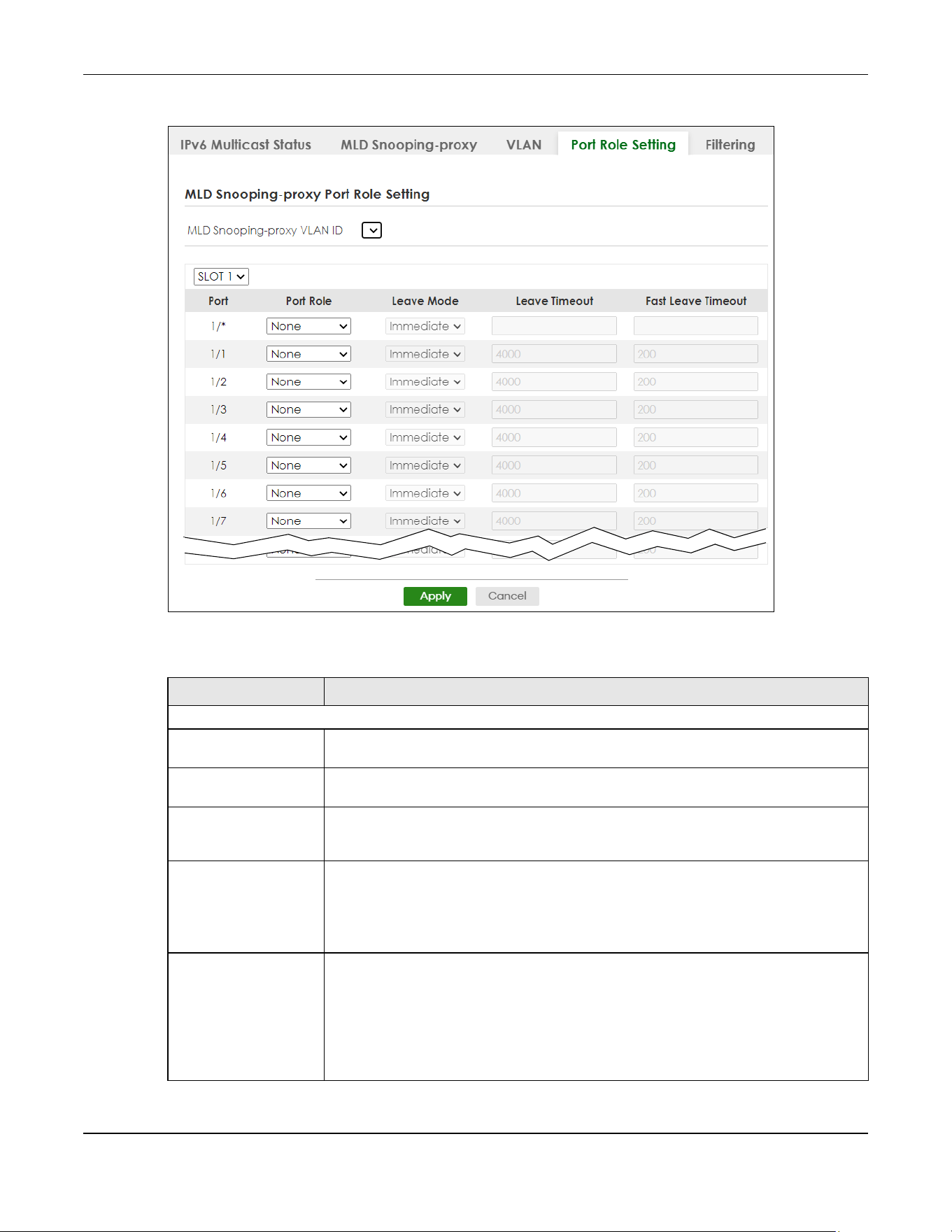
Chapter 46 Multicast
XGS2220 Series User’s Guide
333
Figure 253 SWITCHING > Multicast > IPv6 Multicast > Port Role Setting (Stacking Mode)
The following table describes the fields in the above screen.
Table 154 SWITCHING > Multicast > IPv6 Multicast > Port Role Setting
LABEL DESCRIPTION
MLD Snooping-proxy Port Role Setting
MLD Snooping-proxy
VLAN ID
Select the VLAN ID for which you want to configure a port’s MLD snooping-proxy settings.
SLOT This field appears only in Stacking mode. Click the drop-down list to choose the slot
number of the Switch in a stack.
Port This field displays the port number. In Stacking mode, the first number represents the slot
ID and the second is the port number. Please note that the default stacking ports (the
last four ports of your Switch) cannot be configured. They are reserved for stacking only.
* Settings in this row apply to all ports.
Use this row only if you want to make some settings the same for all ports. Use this row first
to set the common settings and then make adjustments on a port-by-port basis.
Changes in this row are copied to all the ports as soon as you make them.
Port Role A port on the Switch can be either a Downstream port or Upstream port in MLD. A
downstream port connects to MLD hosts and acts as a multicast router to send MLD
queries and listen to the MLD host’s Report and Done messages. An upstream port
connects to a multicast router and works as a host to send Report or Done messages
when receiving queries from a multicast router.
Otherwise, select None if the port is not joining a multicast group or does not belong to
this VLAN.
Chapter 46 Multicast
XGS2220 Series User’s Guide
334
46.10 MLD Snooping-proxy Filtering
Use this screen to configure the Switch’s MLD filtering settings. Click the SWITCHING > Multicast > IPv6
Multicast > Filtering screen to display the screen as shown.
Leave Mode This is configurable only when you select Downstream in the previous Port Role field.
Select the leave mode for the specified downstream ports in this VLAN.
This specifies whether the Switch removes an MLD snooping membership entry (learned
on a downstream port) immediately (Immediate) or wait for an MLD report before the
leave timeout (Normal) or fast leave timeout (Fast) when an MLD leave message is
received on this port from a host.
Leave Timeout Enter the MLD snooping normal leave timeout (in milliseconds) the Switch uses to update
the forwarding table for the specified downstream ports.
This defines how many seconds the Switch waits for an MLD report before removing an
MLD snooping membership entry (learned on a downstream port) when an MLD Done
message is received on this port from a host.
Fast Leave Timeout Enter the fast leave timeout (in milliseconds) for the specified downstream ports.
This defines how many seconds the Switch waits for an MLD report before removing an
MLD snooping membership entry (learned on a downstream port) when an MLD Done
message is received on this port from a host.
Apply Click Apply to save your changes to the Switch’s run-time memory. The Switch loses
these changes if it is turned off or loses power, so use the Save link on the top navigation
panel to save your changes to the non-volatile memory when you are done configuring.
Cancel Click Cancel to reset the fields to your previous configuration.
Table 154 SWITCHING > Multicast > IPv6 Multicast > Port Role Setting (continued)
LABEL DESCRIPTION
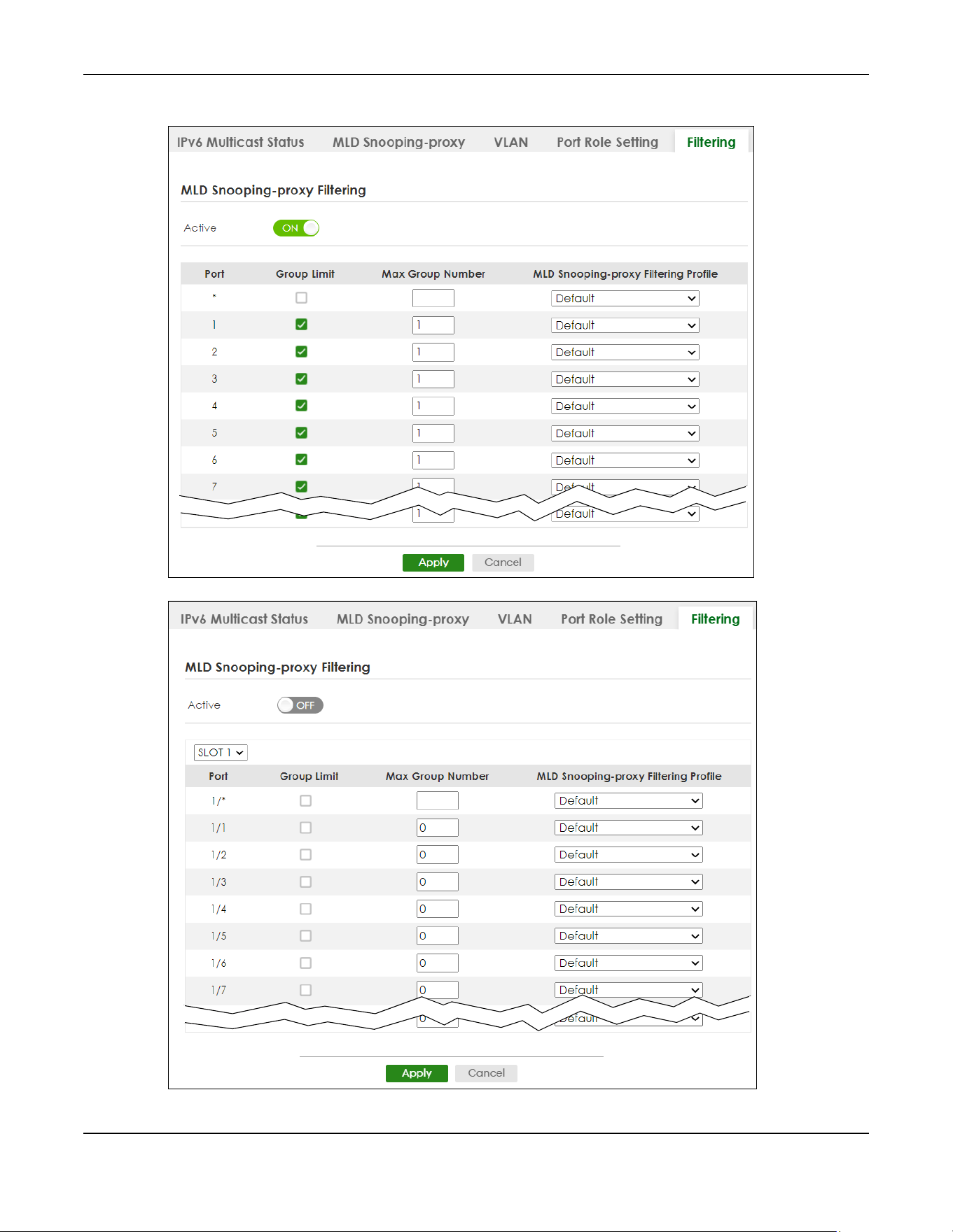
Chapter 46 Multicast
XGS2220 Series User’s Guide
335
Figure 254 SWITCHING > Multicast > IPv6 Multicast > Filtering (Standalone Mode)
Figure 255 SWITCHING > Multicast > IPv6 Multicast > Filtering (Stacking Mode)

Chapter 46 Multicast
XGS2220 Series User’s Guide
336
The following table describes the fields in the above screen.
46.11 MLD Snooping-proxy Filtering Profile
Use this screen to view and create MLD filtering profiles.
Click SWITCHING > Multicast > IPv6 Multicast > Filtering Profile to display the screen as shown.
Figure 256 SWITCHING > Multicast > IPv6 Multicast > Filtering Profile
Table 155 SWITCHING > Multicast > IPv6 Multicast > Filtering
LABEL DESCRIPTION
MLD Snooping-proxy Filtering
Active Enable the switch button to enable MLD filtering on the Switch.
SLOT This field appears only in Stacking mode. Click the drop-down list to choose the slot number
of the Switch in a stack.
Port This field displays the port number. In Stacking mode, the first number represents the slot ID
and the second is the port number. Please note that the default stacking ports (the last four
ports of your Switch) cannot be configured. They are reserved for stacking only.
* Settings in this row apply to all ports.
Use this row only if you want to make some settings the same for all ports. Use this row first to
set the common settings and then make adjustments on a port-by-port basis.
Changes in this row are copied to all the ports as soon as you make them.
Group Limit Select this option to limit the number of multicast groups this port is allowed to join.
Max Group Number Enter the number of multicast groups this port is allowed to join. Once a port is registered in
the specified number of multicast groups, any new MLD Report message is dropped on this
port.
MLD Snooping-proxy
Filtering Profile
Select the name of the MLD filtering profile to use for this port. Otherwise, select Default to
prohibit the port from joining any multicast group.
You can create MLD filtering profiles in the SWITCHING > Multicast > IPv6 Multicast > Filtering
Profile screen.
Apply Click Apply to save your changes to the Switch’s run-time memory. The Switch loses these
changes if it is turned off or loses power, so use the Save link on the top navigation panel to
save your changes to the non-volatile memory when you are done configuring.
Cancel Click Cancel to reset the fields to your previous configuration.

Chapter 46 Multicast
XGS2220 Series User’s Guide
337
The following table describes the fields in the above screen.
46.11.1 Add MLD Snooping-proxy Filtering Profile
Use this screen to create an MLD filtering profile and set the range of the multicast addresses.
Click Add Profile in the SWITCHING > Multicast > IPv6 Multicast > Filtering Profile to display the screen as
shown.
Figure 257 SWITCHING > Multicast > IPv6 Multicast > Filtering Profile > Add Profile
The following table describes the fields in the above screen.
Table 156 SWITCHING > Multicast > IPv6 Multicast > Filtering Profile
LABEL DESCRIPTION
MLD Snooping-proxy Filtering Profile
Profile Name This field displays the descriptive name of the profile.
Start Address This field displays the start of the multicast IPv6 address range.
End Address This field displays the end of the multicast IPv6 address range.
Select an entry’s check box to select a specific entry. Otherwise, select the check box in the
table heading row to select all entries.
Add Profile Click this to add a new MLD Snooping-proxy filtering profile.
Add Rule Click Add Rule to add a new rule and specify the profile it belongs to in the Add Rule screen.
You can also select a profile entry and click Add Rule to add an additional rule for the
selected profile.
Delete Select a profile and click Delete to remove the selected profile and the accompanying
rules.
Select a rule from a profile and click Delete to remove the selected rule.
Table 157 SWITCHING > Multicast > IPv6 Multicast > Filtering Profile > Add Profile
LABEL DESCRIPTION
Profile Name Enter a descriptive name (up to 32 printable ASCII characters except [?], [|], [‘], [“], [,]) for
the profile for identification purposes.
To configure additional rules for a profile that you have already added, enter the profile
name and specify a different IP multicast address range.
Start Address Enter the starting multicast IPv6 address for a range of multicast IPv6 addresses that you
want to belong to the MLD filtering profile.

Chapter 46 Multicast
XGS2220 Series User’s Guide
338
46.11.2 Add MLD Snooping-proxy Filtering Rule
Use this screen to create a multicast addresses range rule of the MLD filtering profile.
Click Add Rule in the SWITCHING > Multicast > IPv6 Multicast > Filtering Profile to display this screen.
Figure 258 SWITCHING > Multicast > IPv6 Multicast > Filtering Profile > Add Rule
The following table describes the fields in the above screen.
46.12 MVR Configuration
Use this screen to view and create multicast VLANs.
End Address Enter the ending multicast IPv6 address for a range of IPv6 addresses that you want to
belong to the MLD filtering profile.
If you want to add a single multicast IPv6 address, enter it in both the Start Address and End
Address fields.
Apply Click Apply to save your changes to the Switch’s run-time memory. The Switch loses these
changes if it is turned off or loses power, so use the Save link on the top navigation panel to
save your changes to the non-volatile memory when you are done configuring.
Clear Click Clear to clear the fields to the factory defaults.
Cancel Click Cancel to not save the configuration you make and return to the last screen.
Table 157 SWITCHING > Multicast > IPv6 Multicast > Filtering Profile > Add Profile (continued)
LABEL DESCRIPTION
Table 158 SWITCHING > Multicast > IPv6 Multicast > Filtering Profile > Add Rule
LABEL DESCRIPTION
Profile Name Select a profile from the drop-down list to add a additional rule for the existing profile.
Start Address Enter the starting multicast IPv6 address for a range of multicast IPv6 addresses that you
want to belong to the MLD filtering profile.
End Address Enter the ending multicast IPv6 address for a range of IPv6 addresses that you want to
belong to the MLD filtering profile.
If you want to add a single multicast IPv6 address, enter it in both the Start Address and End
Address fields.
Apply Click Apply to save your changes to the Switch’s run-time memory. The Switch loses these
changes if it is turned off or loses power, so use the Save link on the top navigation panel to
save your changes to the non-volatile memory when you are done configuring.
Clear Click Clear to clear the fields to the factory defaults.
Cancel Click Cancel to not save the configuration you make and return to the last screen.
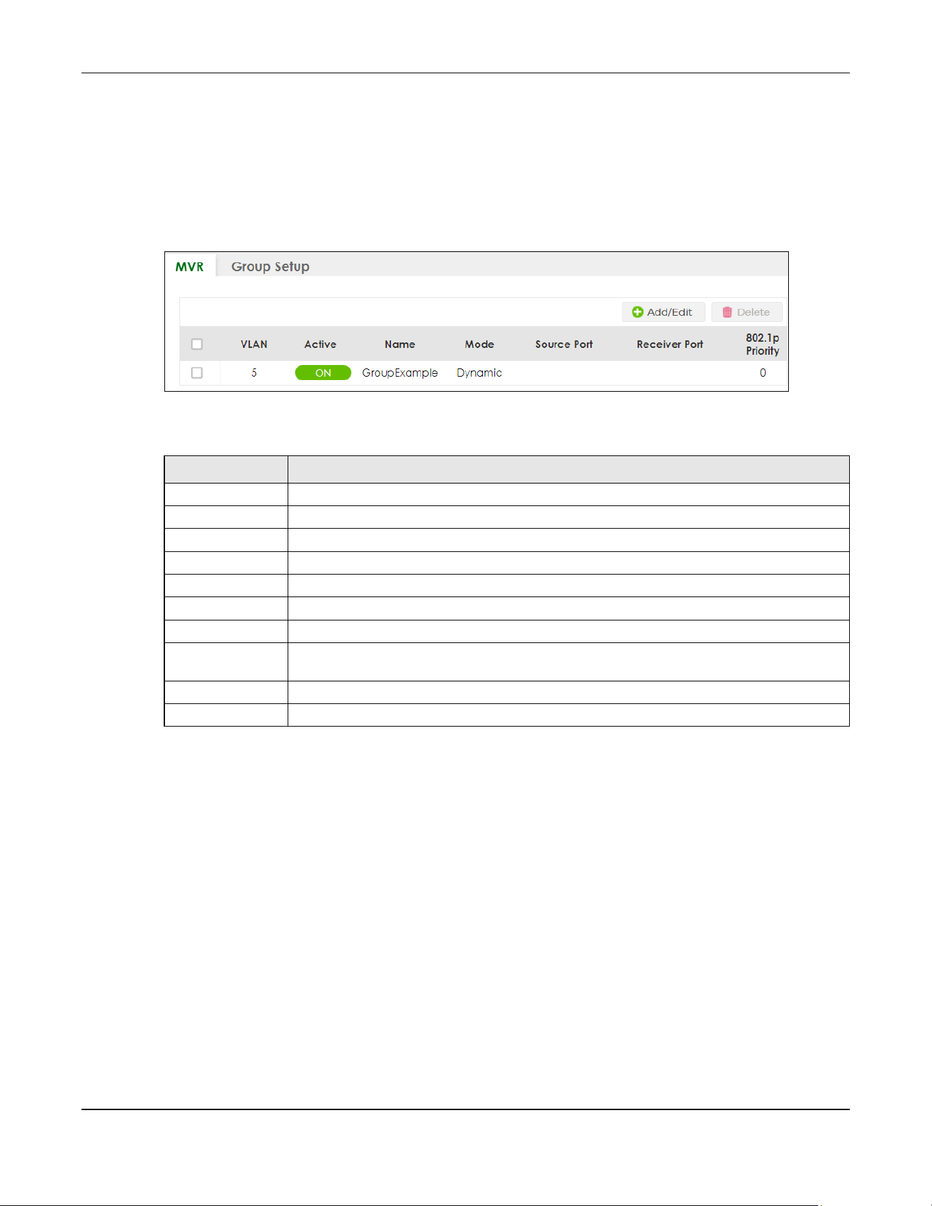
Chapter 46 Multicast
XGS2220 Series User’s Guide
339
Click SWITCHING > Multicast > MVR to display the screen as shown next.
Note: You can create up to five multicast VLANs and up to 256 multicast rules on the Switch.
Note: Your Switch automatically creates a static VLAN (with the same VID) when you create
a multicast VLAN in this screen.
Figure 259 SWITCHING > Multicast > MVR
The following table describes the related labels in this screen.
46.12.1 Add/Edit MVR
Use this screen to create or edit multicast VLANs and select the receiver ports and a source port for
each multicast VLAN.
To access this screen, click Add/Edit or select an existing entry and click Add/Edit in the SWITCHING >
Multicast > MVR screen.
Table 159 SWITCHING > Multicast > MVR
LABEL DESCRIPTION
VLAN This field displays the multicast VLAN ID.
Active This field displays whether the multicast group is enabled or not.
Name This field displays the descriptive name for this setting.
Mode This field displays the MVR mode.
Source Port This field displays the source port numbers.
Receiver Port This field displays the receiver port numbers.
802.1p Priority This field displays the priority level.
Select an entry’s check box to select a specific entry. Otherwise, select the check box in the
table heading row to select all entries.
Add/Edit Click Add/Edit to add a new multicast VLAN or edit a selected one.
Delete Select the entries that you want to remove, then click Delete to delete multicast VLANs.
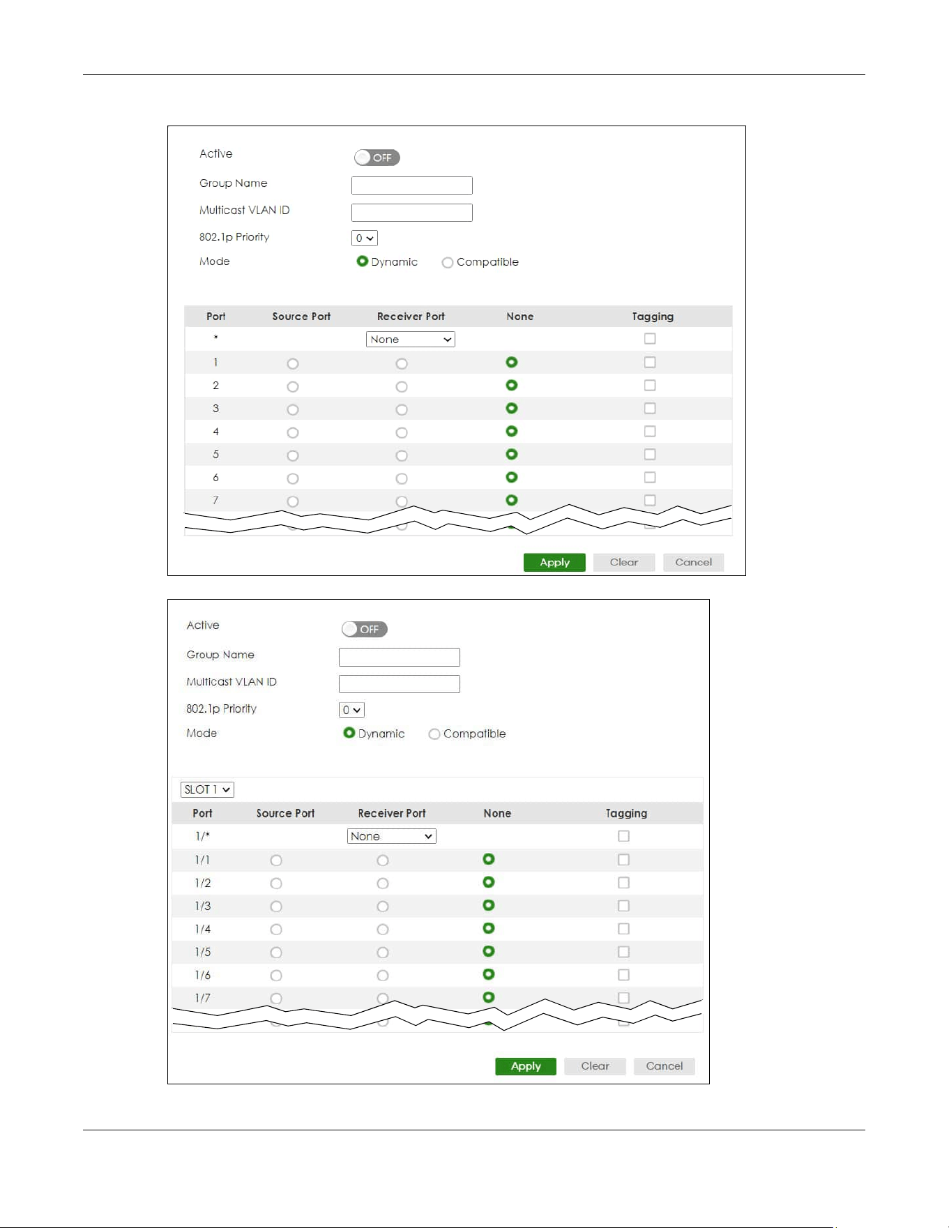
Chapter 46 Multicast
XGS2220 Series User’s Guide
340
Figure 260 SWITCHING > Multicast > MVR > Add/Edit (Standalone Mode)
Figure 261 SWITCHING > Multicast > MVR > Add/Edit (Stacking Mode)

Chapter 46 Multicast
XGS2220 Series User’s Guide
341
The following table describes the related labels in this screen.
46.13 MVR Group Setup
All source ports and receiver ports belonging to a multicast group can receive multicast data sent to this
multicast group.
Use this screen to view and configure MVR IP multicast group settings. Click SWITCHING > Multicast >
MVR > Group Setup to access this screen.
Note: A port can belong to more than one multicast VLAN. However, IP multicast group
addresses in different multicast VLANs cannot overlap.
Table 160 SWITCHING > Multicast > MVR > Add/Edit
LABEL DESCRIPTION
Active Enable the switch button to enable MVR to allow one single multicast VLAN to be shared
among different subscriber VLANs on the network.
Group Name Enter a descriptive name (up to 32 printable ASCII characters except [ ? ], [ | ], [ ' ], [ " ], or [ ,
]) for identification purposes.
Multicast VLAN ID Enter the VLAN ID (1 to 4094) of the multicast VLAN.
802.1p Priority Select a priority level (0 – 7) with which the Switch replaces the priority in outgoing IGMP or
MLD control packets (belonging to this multicast VLAN).
Mode Specify the MVR mode on the Switch. Choices are Dynamic and Compatible.
Select Dynamic to send IGMP reports or MLD messages to all MVR source ports in the multicast
VLAN.
Select Compatible to set the Switch not to send IGMP reports or MLD messages.
Use this section to configure MVR settings on each port.
SLOT This field appears only in Stacking mode. Click the drop-down list to choose the slot number of
the Switch in a stack.
Port This field displays the port number. In Stacking mode, the first number represents the slot ID
and the second is the port number. Please note that the default stacking ports (the last four
ports of your Switch) cannot be configured. They are reserved for stacking only.
* Settings in this row apply to all ports.
Use this row only if you want to make some settings the same for all ports. Use this row first to
set the common settings and then make adjustments on a port-by-port basis.
Changes in this row are copied to all the ports as soon as you make them.
Source Port Select this option to set this port as the MVR source port that sends and receives multicast
traffic. All source ports must belong to a single multicast VLAN.
Receiver Port Select this option to set this port as a receiver port that only receives multicast traffic.
None Select this option to set the port not to participate in MVR. No MVR multicast traffic is sent or
received on this port.
Tagging Select this check box if you want the port to tag the VLAN ID in all outgoing frames
transmitted.
Apply Click Apply to save your changes to the Switch’s run-time memory. The Switch loses these
changes if it is turned off or loses power, so use the Save link on the top navigation panel to
save your changes to the non-volatile memory when you are done configuring.
Clear Click Clear to clear the fields to the factory defaults.
Cancel Click Cancel to not save the configuration you make and return to the last screen.
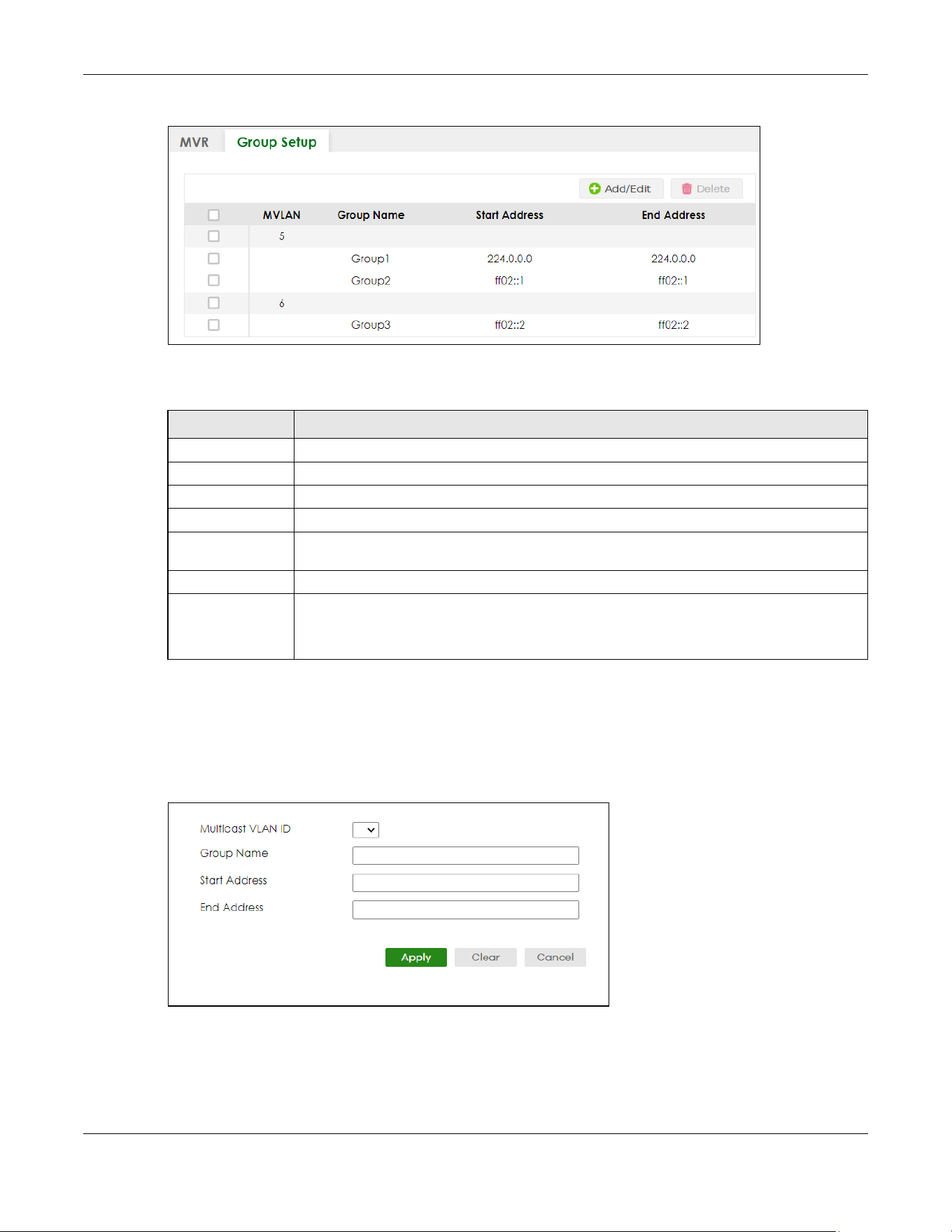
Chapter 46 Multicast
XGS2220 Series User’s Guide
342
Figure 262 SWITCHING > Multicast > MVR > Group Setup
The following table describes the labels in this screen.
46.13.1 Add/Edit MVR Group
Use this screen to configure MVR IP multicast group addresses. To access this screen, click the Add/Edit
button or select an entry from the list and click the Add/Edit button.
Figure 263 SWITCHING > Multicast > MVR > Group Setup > Add/Edit
Table 161 SWITCHING > Multicast > MVR > Group Setup
LABEL DESCRIPTION
MVLAN This field displays the multicast VLAN ID.
Group Name This field displays the descriptive name for this setting.
Start Address This field displays the starting IP address of the multicast group.
End Address This field displays the ending IP address of the multicast group.
Select an entry’s check box to select a specific entry. Otherwise, select the check box in the
table heading row to select all entries.
Add/Edit Click Add/Edit to add a new multicast group or edit a selected one.
Delete Select the group entries that you want to remove, then click Delete to delete the selected
multicast groups.
If you delete a multicast VLAN, all multicast groups in this VLAN will also be removed.
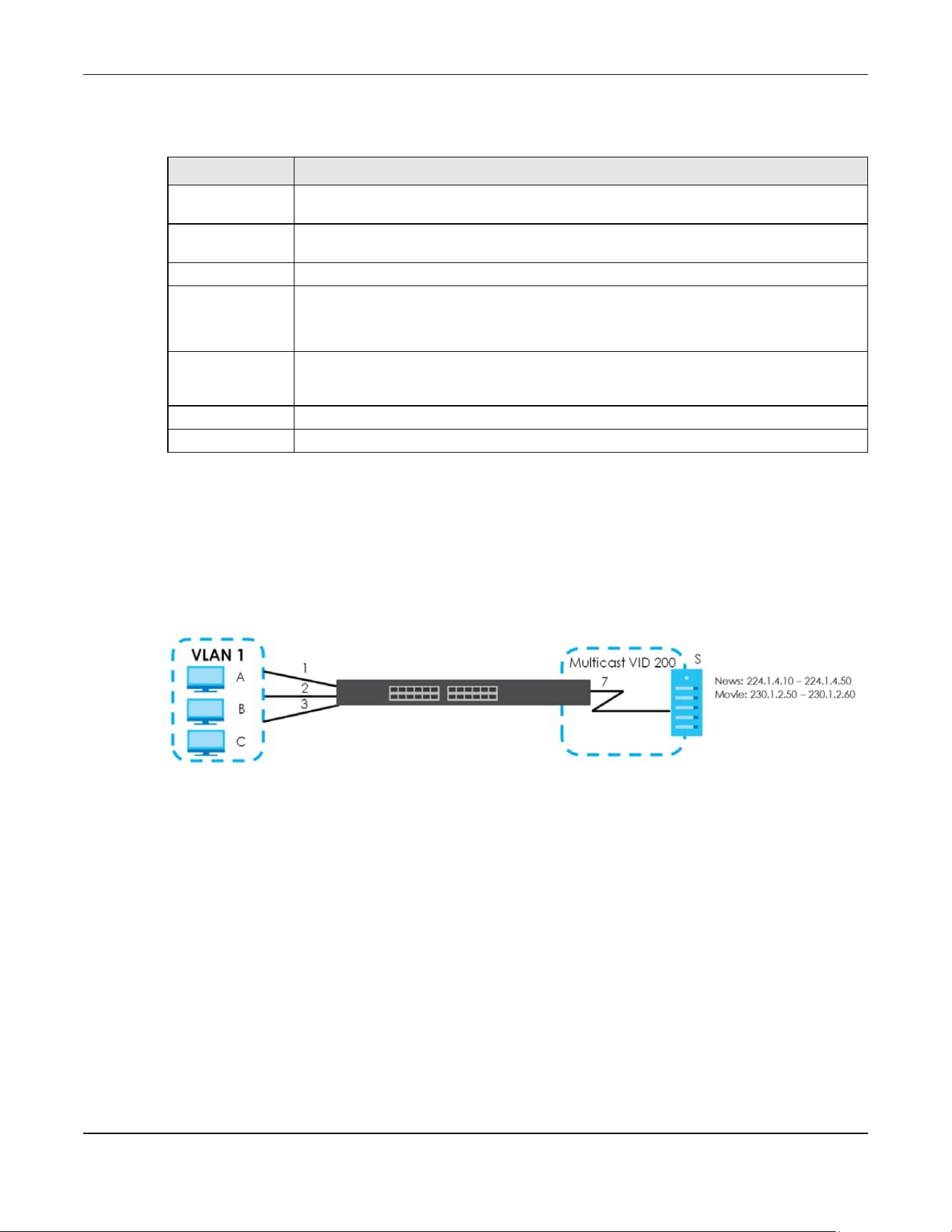
Chapter 46 Multicast
XGS2220 Series User’s Guide
343
The following table describes the labels in this screen.
46.13.2 MVR Configuration Example
The following figure shows a network example where ports 1, 2 and 3 on the Switch belong to VLAN 1. In
addition, port 7 belongs to the multicast group with VID 200 to receive multicast traffic (the News and
Movie channels) from the remote streaming media server, S. Computers A, B and C in VLAN 1 are able
to receive the traffic.
Figure 264 MVR Configuration Example
To configure the MVR settings on the Switch, click the Add/Edit button in the SWITCHING > Multicast >
MVR screen. Create a multicast VLAN and set the receiver and source ports.
Table 162 SWITCHING > Multicast > MVR > Group Setup > Add/Edit
LABEL DESCRIPTION
Multicast VLAN ID Select a multicast VLAN ID (that you configured in the MVR screen) from the drop-down list
box.
Group Name Enter a descriptive name for identification purposes. You can enter up to 32 printable ASCII
characters except [ ? ], [ | ], [ ' ], [ " ] or [ , ].
Start Address Enter the starting IP multicast address of the multicast group in dotted decimal notation.
End Address Enter the ending IP multicast address of the multicast group in dotted decimal notation.
Enter the same IP address as the Start Address field if you want to configure only one IP
address for a multicast group.
Apply Click Apply to save your changes to the Switch’s run-time memory. The Switch loses these
changes if it is turned off or loses power, so use the Save link on the top navigation panel to
save your changes to the non-volatile memory when you are done configuring.
Clear Click Clear to clear the fields to the factory defaults.
Cancel Click Cancel to not save the configuration you make and return to the last screen.
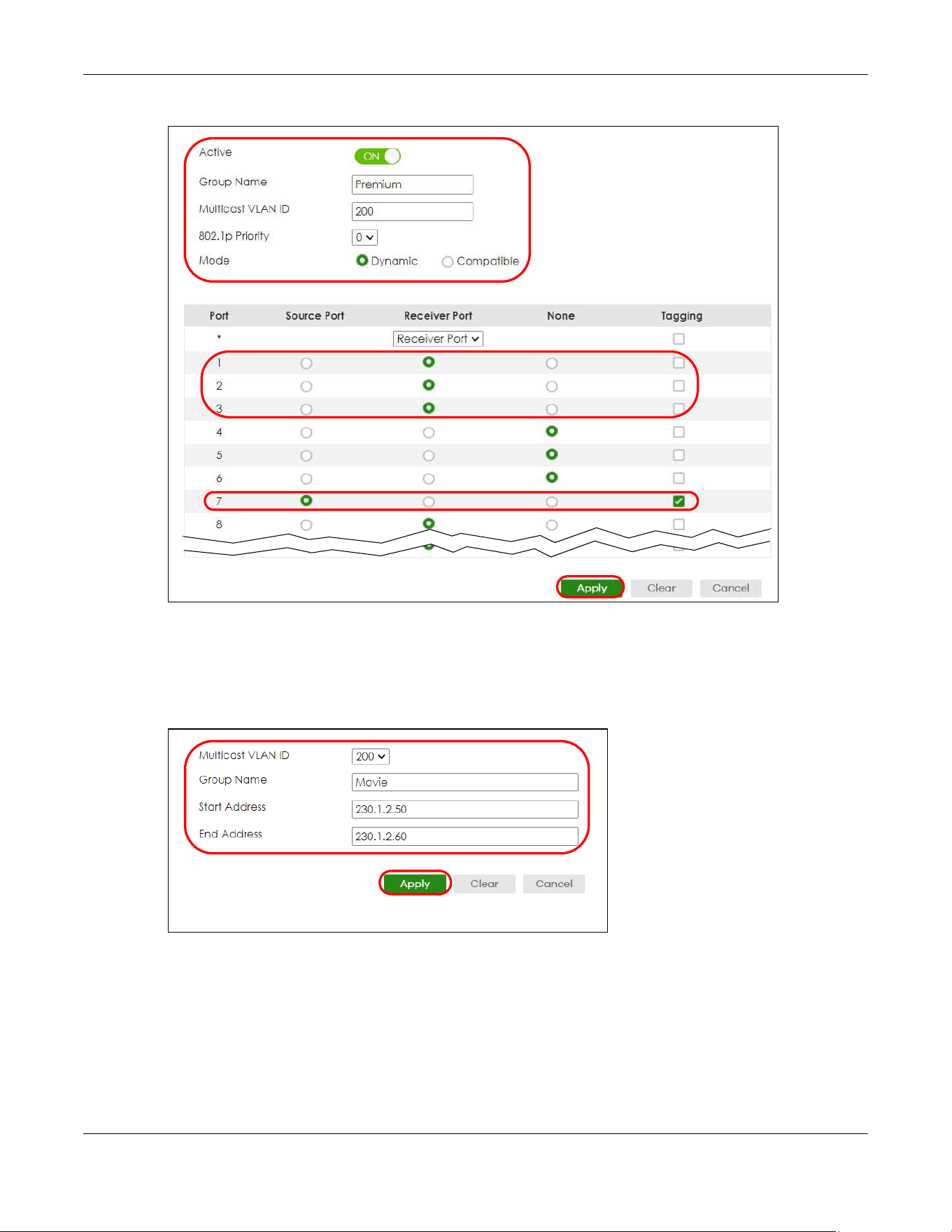
Chapter 46 Multicast
XGS2220 Series User’s Guide
344
Figure 265 MVR Configuration Example
To set the Switch to forward the multicast group traffic to the subscribers, click Add/Edit in the
SWITCHING > Multicast > MVR > Group Setup screen and configure multicast group settings. The
following figure shows an example where two IPv4 multicast groups (News and Movie) are configured
for the multicast VLAN 200.
Figure 266 MVR Group Configuration Example – Add

Chapter 46 Multicast
XGS2220 Series User’s Guide
345
Figure 267 MVR Group Configuration Example – View

Chapter 47 Static Multicast Forwarding
XGS2220 Series User’s Guide
346
CHAPTER 47
Static Multicast Forwarding
47.1 Static Multicast Forwarding Overview
This chapter discusses how to configure static multicast forwarding rules based on multicast MAC
addresses or multicast IPv4 addresses.
Use these screens to configure static multicast address forwarding by defining the ports and VLANs that
multicast traffic can pass through the Switch. If a subscriber is on a different port or VLAN, then the
subscriber will not get the multicast.
47.1.1 What You Can Do
Use the Static Multicast Forwarding By MAC screen (Section 47.2 on page 347) to configure rules to
forward specific multicast frames, such as streaming or control frames, to specific ports.
Use the Static Multicast Forwarding By IP screen (Section 47.3 on page 349) to configure static multicast
IPv4 addresses for ports to receive the multicast stream.
47.1.2 What You Need To Know
A multicast MAC address or multicast IP address is the MAC address or IP address of a multicast group,
and not a receiving device.
A static multicast address is a multicast MAC address or multicast IPv4 address that has been manually
entered in the multicast table. This identifies the destination of the multicast content. Multicast IPv4
addresses uses the Class D IP addresses range 224.0.0.0 to 239.255.255.255. Multicast MAC addresses
have a “1” as the last binary bit of the first octet pair (for example, 01:00:5e:00:00:0A). Static multicast
addresses do not age out. See IP Multicast Addresses on page 316 for more information on IP multicast
addresses.
Note: Static (manual) multicast forwarding allows you (the administrator) to forward multicast
frames to a member without the member having to join the group first.
If a multicast group has no members, then the Switch cannot forward to specific ports unless you
configure static (manual) multicast entries. The Switch will either flood the multicast frames to all ports
(default) or drop them. Figure 268 on page 347 shows such unknown multicast frames flooded to all
ports. With static multicast forwarding, you can forward these multicasts to ports within a VLAN group.
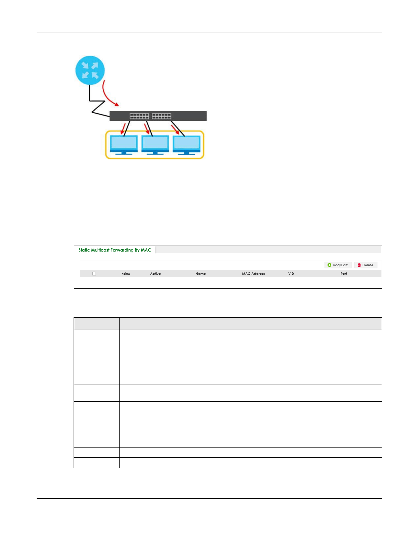
Chapter 47 Static Multicast Forwarding
XGS2220 Series User’s Guide
347
Figure 268 No Multicast Forwarding
47.2 Static Multicast Forwarding By MAC
Use this screen to view and configure static multicast MAC addresses for ports to receive the multicast
stream. Click SWITCHING > Multicast > Static Multicast Forwarding By MAC to display the screen as
shown next.
Figure 269 SWITCHING > Multicast > Static Multicast Forwarding By MAC
The following table describes the labels in this screen.
Table 163 SWITCHING > Multicast > Static Multicast Forwarding By MAC
LABEL DESCRIPTION
Index This is the index number of the static multicast MAC address rule.
Active This field displays whether a static multicast MAC address forwarding rule is active or not. You may
temporarily deactivate a rule without deleting it.
Name This field displays the descriptive name for identification purposes for a static multicast MAC
address-forwarding rule.
MAC Address This field displays the multicast MAC address that identifies a multicast group.
VID This field displays the ID number of a VLAN group to which frames containing the specified
multicast MAC address will be forwarded.
Port This field displays the ports within an identified VLAN group to which frames containing the
specified multicast MAC address will be forwarded.
In Stacking mode, the first number represents the slot ID and the second is the port number.
Select an entry’s check box to select a specific entry. Otherwise, select the check box in the
table heading row to select all entries.
Add/Edit Click Add/Edit to add a new rule or edit a selected one.
Delete Click Delete to remove the selected rules.

Chapter 47 Static Multicast Forwarding
XGS2220 Series User’s Guide
348
47.2.1 Add/Edit Static Multicast Forwarding By MAC
Use this screen to add a static multicast MAC address rule for ports to receive the multicast stream.
Click Add/Edit, or select an entry and click Add/Edit in the SWITCHING > Multicast > Static Multicast
Forwarding By MAC to display this screen.
Figure 270 SWITCHING > Multicast > Static Multicast Forwarding By MAC > Add/Edit
The following table describes the labels in this screen.
Table 164 SWITCHING > Multicast > Static Multicast Forwarding By MAC > Add/Edit
LABEL DESCRIPTION
Active Enable the switch button to activate your rule. You may temporarily deactivate a rule without
deleting it by disabling the switch.
Name Enter a descriptive name (up to 32 printable ASCII characters except [ ? ], [ | ], [ ' ], [ " ] or [ , ]) for
this static multicast MAC address forwarding rule. This is for identification only.
MAC Address Enter a multicast MAC address which identifies the multicast group. The last binary bit of the first
octet pair in a multicast MAC address must be 1. For example, the first octet pair 00000001 is 01 in
hexadecimal, so 01:00:5e:00:00:0A and 01:00:5e:00:00:27 are valid multicast MAC addresses.
VID You can forward frames with matching destination multicast MAC address to ports within a VLAN
group. Enter the ID that identifies the VLAN group here. If you do NOT have a specific target
VLAN, enter 1.
Port Enter the ports where frames with destination MAC address that matched the entry above are
forwarded. You can enter multiple ports separated by (no space) comma (,) or hyphen (-) for a
range. For example, enter “3-5” for ports 3, 4, and 5. Enter “3,5,7” for ports 3, 5, and 7.
In Stacking mode, the first number represents the slot ID and the second is the port number. Enter
“1/1-1/24,2/23” for ports 1 to 24 for the Switch in slot 1 and port 23 for the Switch in slot 2, for
example.
Apply Click Apply to save your changes to the Switch’s run-time memory. The Switch loses these
changes if it is turned off or loses power, so use the Save link on the top navigation panel to save
your changes to the non-volatile memory when you are done configuring.
Clear Click Clear to clear the fields to the factory defaults.
Cancel Click Cancel to not save the configuration you make and return to the last screen.
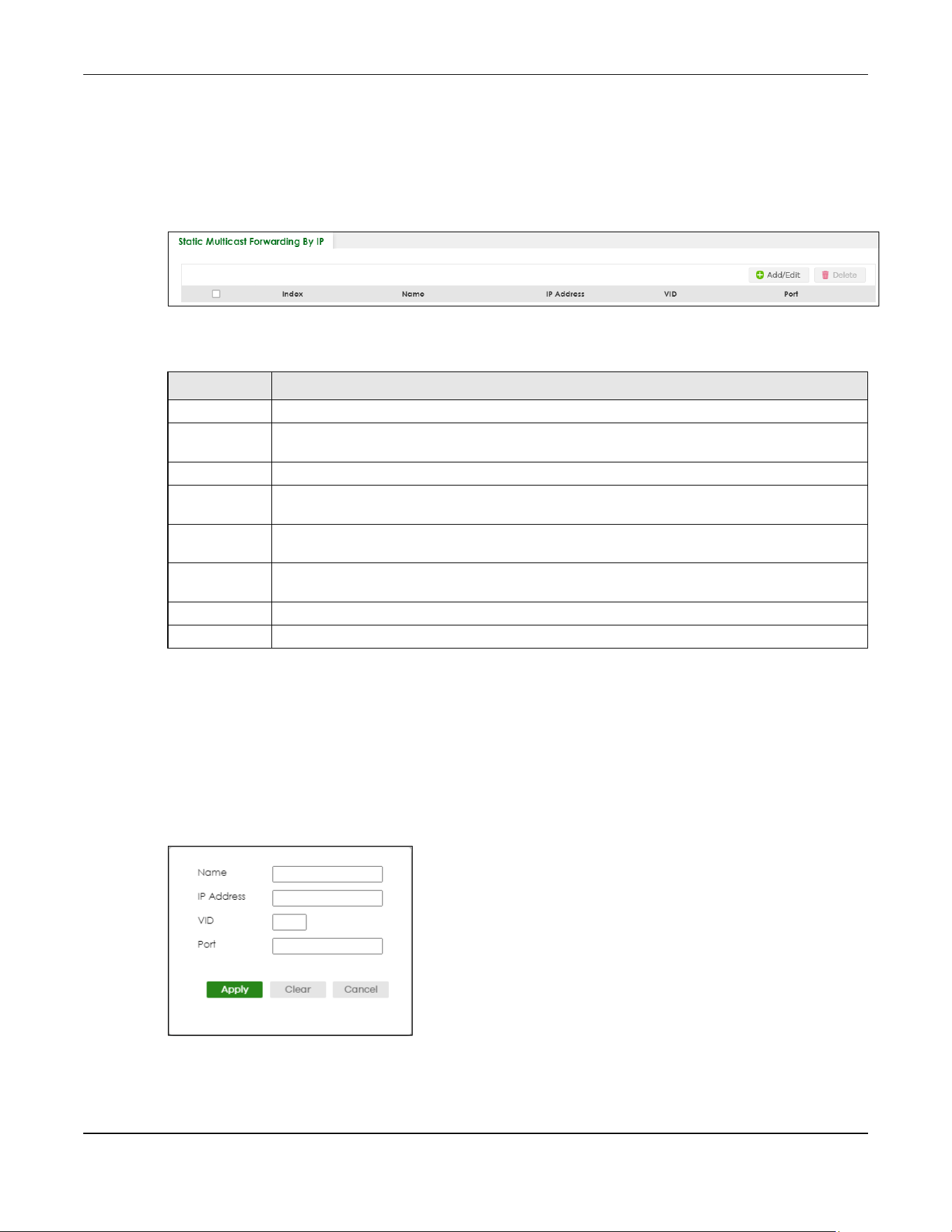
Chapter 47 Static Multicast Forwarding
XGS2220 Series User’s Guide
349
47.3 Configure a Static Multicast IPv4 Address
Use this screen to configure static multicast IPv4 addresses for ports to receive the multicast stream. Click
SWITCHING > Multicast > Static Multicast Forwarding By IP to display the screen as shown next.
Figure 271 SWITCHING > Multicast > Static Multicast Forwarding By IP
The following table describes the labels in this screen.
47.3.1 Add/Edit a Static Multicast Address By IP
Use this screen to configure ports and VLAN to receive the multicast stream with this multicast IPv4
address.
Click Add/Edit, or select an entry and click Add/Edit in the SWITCHING > Multicast > Static Multicast
Forwarding By IP to display this screen.
Figure 272 SWITCHING > Multicast > Static Multicast Forwarding By IP > Add/Edit
Table 165 SWITCHING > Multicast > Static Multicast Forwarding By IP
LABEL DESCRIPTION
Index This is the index number of the static multicast IP address rule.
Name This field displays the descriptive name for identification purposes for a static multicast IP address-
forwarding rule.
IP Address This field displays the multicast IP address that identifies a multicast group.
VID This field displays the ID number of a VLAN group to which frames containing the specified
multicast IP address will be forwarded.
Port This field displays the ports within an identified VLAN group to which frames containing the
specified multicast IP address will be forwarded.
Select an entry’s check box to select a specific entry. Otherwise, select the check box in the
table heading row to select all entries.
Add/Edit Click Add/Edit to add a new rule or edit a selected one.
Delete Click Delete to remove the selected rules.
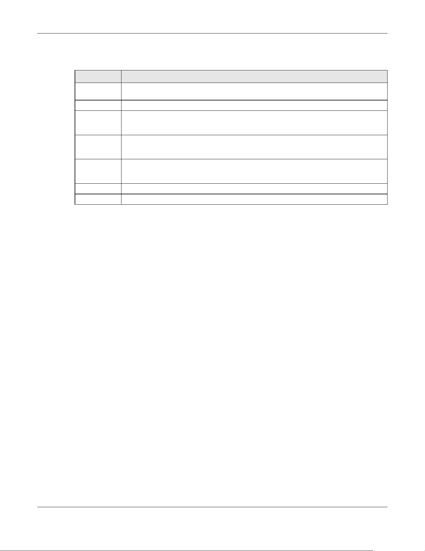
Chapter 47 Static Multicast Forwarding
XGS2220 Series User’s Guide
350
The following table describes the labels in this screen.
Table 166 SWITCHING > Multicast > Static Multicast Forwarding By IP > Add/Edit
LABEL DESCRIPTION
Name Enter a descriptive name (up to 32 printable ASCII characters except [ ? ], [ | ], [ ' ], [ " ] or [ , ]) for
this static multicast IPv4 address forwarding rule. This is for identification only.
IP Address Enter a multicast IPv4 address (224.0.0.0 – 239.255.255.255) which identifies the multicast group.
VID You can forward frames with matching destination multicast IPv4 address to ports within a VLAN
group. Enter the ID that identifies the VLAN group here. If you do NOT have a specific target
VLAN, enter 1.
Port Enter the ports where frames with destination multicast IPv4 address that matched the entry
above are forwarded. You can enter multiple ports separated by (no space) comma (,) or
hyphen (-). For example, enter “3-5” for ports 3, 4, and 5. Enter “3,5,7” for ports 3, 5, and 7.
Apply Click Apply to save your changes to the Switch’s run-time memory. The Switch loses these
changes if it is turned off or loses power, so use the Save link on the top navigation panel to save
your changes to the non-volatile memory when you are done configuring.
Clear Click Clear to clear the fields to the factory defaults.
Cancel Click Cancel to not save the configuration you make and return to the last screen.

Chapter 48 PPPoE
XGS2220 Series User’s Guide
351
CHAPTER 48
PPPoE
48.1 PPPoE Intermediate Agent Overview
This chapter describes how the Switch gives a PPPoE termination server additional information that the
server can use to identify and authenticate a PPPoE client.
A PPPoE Intermediate Agent (PPPoE IA) is deployed between a PPPoE server and PPPoE clients. It helps
the PPPoE server identify and authenticate clients by adding subscriber line specific information to
PPPoE discovery packets from clients on a per-port or per-port-per-VLAN basis before forwarding them
to the PPPoE server.
48.1.1 What You Can Do
• Use the PPPoE Intermediate Agent screen (Section 48.2 on page 353) to enable the PPPoE
Intermediate Agent on the Switch.
• Use the PPPoE IA Port screen (Section 48.3 on page 355) to set the port state and configure PPPoE
intermediate agent sub-options on a per-port basis.
• Use the PPPoE IA Port VLAN screen (Section 48.4 on page 356) to configure PPPoE IA settings that
apply to a specific VLAN on a port.
• Use the PPPoE IA VLAN (Section 48.5 on page 358) to enable the PPPoE Intermediate Agent on a
VLAN.
48.1.2 What You Need to Know
Read on for concepts on ARP that can help you configure the screen in this chapter.
48.1.2.1 PPPoE Intermediate Agent Tag Format
If the PPPoE Intermediate Agent is enabled, the Switch adds a vendor-specific tag to PADI (PPPoE
Active Discovery Initialization) and PADR (PPPoE Active Discovery Request) packets from PPPoE clients.

Chapter 48 PPPoE
XGS2220 Series User’s Guide
352
This tag is defined in RFC 2516 and has the following format for this feature.
The Tag_Type is 0x0105 for vendor-specific tags, as defined in RFC 2516. The Tag_Len indicates the
length of Value, i1 and i2. The Value is the 32-bit number 0x00000DE9, which stands for the “ADSL Forum”
IANA entry. i1 and i2 are PPPoE intermediate agent sub-options, which contain additional information
about the PPPoE client.
48.1.2.2 Sub-Option Format
There are two types of sub-option: “Agent Circuit ID Sub-option” and “Agent Remote ID Sub-option”.
They have the following formats.
The 1 in the first field identifies this as an Agent Circuit ID sub-option and 2 identifies this as an Agent
Remote ID sub-option. The next field specifies the length of the field. The Switch takes the Circuit ID string
you manually configure for a VLAN on a port as the highest priority and the Circuit ID string for a port as
the second priority. In addition, the Switch puts the PPPoE client’s MAC address into the Agent Remote
ID Sub-option if you do not specify any user-defined string.
Flexible Circuit ID Syntax with Identifier String and Variables
If you do not configure a Circuit ID string for a VLAN on a specific port or for a specific port, the Switch
adds the user-defined identifier string and variables into the Agent Circuit ID Sub-option. The variables
can be the slot ID of the PPPoE client, the port number of the PPPoE client and/or the VLAN ID on the
PPPoE packet.
The identifier-string, slot ID, port number and VLAN ID are separated from each other by a pound key
(#), semi-colon (;), period (.), comma (,), forward slash (/) or space. An Agent Circuit ID Sub-option
example is “Switch/07/0123” and indicates the PPPoE packets come from a PPPoE client which is
connected to the Switch’s port 7 and belong to VLAN 123.
Table 167 PPPoE Intermediate Agent Vendor-specific Tag Format
Tag_Type
(0x0105)
Tag_Len Value i1 i2
Table 168 PPPoE IA Circuit ID Sub-option Format: User-defined String
SubOpt Length Value
0x01
(1 byte)
N
(1 byte)
String
(63 bytes)
Table 169 PPPoE IA Remote ID Sub-option Format
SubOpt Length Value
0x02
(1 byte)
N
(1 byte)
MAC Address or String
(63 bytes)
Table 170 PPPoE IA Circuit ID Sub-option Format: Using Identifier String and Variables
SubOpt Length Value
0x01
(1 byte)
N
(1 byte)
Identifier
String
(53 byte)
delimiter
(1 byte)
Slot ID
(1 byte)
delimiter
(1 byte)
Port No
(2 byte)
delimiter
(1 byte)
VLAN ID
(4
bytes)

Chapter 48 PPPoE
XGS2220 Series User’s Guide
353
WT-101 Default Circuit ID Syntax
If you do not configure a Circuit ID string for a specific VLAN on a port or for a specific port, and disable
the flexible Circuit ID syntax in the PPPoE > Intermediate Agent screen, the Switch automatically
generates a Circuit ID string according to the default Circuit ID syntax which is defined in the DSL Forum
Working Text (WT)-101. The default access node identifier is the host name of the PPPoE intermediate
agent and the eth indicates “Ethernet”.
48.1.2.3 Port State
Every port is either a trusted port or an untrusted port for the PPPoE intermediate agent. This setting is
independent of the trusted or untrusted setting for DHCP snooping or ARP inspection. You can also
specify the agent sub-options (circuit ID and remote ID) that the Switch adds to PADI and PADR packets
from PPPoE clients.
Trusted ports are connected to PPPoE servers.
• If a PADO (PPPoE Active Discovery Offer), PADS (PPPoE Active Discovery Session-confirmation), or
PADT (PPPoE Active Discovery Terminate) packet is sent from a PPPoE server and received on a
trusted port, the Switch forwards it to all other ports.
• If a PADI or PADR packet is sent from a PPPoE client but received on a trusted port, the Switch
forwards it to other trusted ports.
Note: The Switch will drop all PPPoE discovery packets if you enable the PPPoE intermediate
agent and there are no trusted ports.
Untrusted ports are connected to subscribers.
• If a PADI, PADR, or PADT packet is sent from a PPPoE client and received on an untrusted port, the
Switch adds a vendor-specific tag to the packet and then forwards it to the trusted ports.
• The Switch discards PADO and PADS packets which are sent from a PPPoE server but received on an
untrusted port.
48.2 PPPoE Intermediate Agent
Use this screen to configure the Switch to give a PPPoE termination server additional subscriber
information that the server can use to identify and authenticate a PPPoE client.
Click SWITCHING > PPPoE Intermediate Agent to display the screen as shown.
Table 171 PPPoE IA Circuit ID Sub-option Format: Defined in WT-101
SubOpt Length Value
0x01
(1 byte)
N
(1 byte)
Access
Node
Identifier
(20 byte)
Space
(1
byte)
eth
(3
byte)
Space
(1
byte)
Slot ID
(1
byte)
/
(1
byte)
Port No
(2 byte)
:
(1
byte)
VLAN ID
(4
bytes)
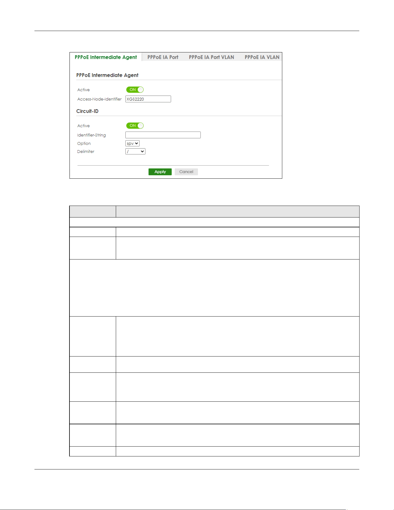
Chapter 48 PPPoE
XGS2220 Series User’s Guide
354
Figure 273 SWITCHING > PPPoE Intermediate Agent > PPPoE Intermediate Agent
The following table describes the labels in this screen.
Table 172 SWITCHING > PPPoE Intermediate Agent > PPPoE Intermediate Agent
LABEL DESCRIPTION
PPPoE Intermediate Agent
Active Enable the switch button to enable the PPPoE intermediate agent globally on the Switch.
Access-
Node-
Identifier
Enter up to 20 ASCII printable characters (except [ ? ], [ | ], [ ' ], [ " ], or [ , ]) to identify the PPPoE
intermediate agent. Hyphens (-) and spaces are also allowed. The default is the Switch’s host
name.
Circuit-ID
Use this section to configure the Circuit ID field in the PADI and PADR packets.
The Circuit ID you configure for a specific port (in the SWITCHING > PPPoE Intermediate Agent > PPPoE IA Port
screen) or for a specific VLAN on a port (in the SWITCHING > PPPoE Intermediate Agent > PPPoE IA Port VLAN
screen) has priority over this. That means, if you also want to configure PPPoE IA Per-Port or Per-Port Per-VLAN
setting, leave the fields here empty and configure circuit-id and remote-id in the Per-Port or Per-Port Per-VLAN
screen.
Active Enable the switch button to have the Switch add the user-defined identifier string and variables
(specified in the Option field) to PADI or PADR packets from PPPoE clients.
If you leave this option unselected and do not configure any Circuit ID string (using CLI
commands) on the Switch, the Switch will use the string specified in the Access-Node-Identifier
field.
Identifier-
String
Specify a string that the Switch adds in the Agent Circuit ID sub-option. You can enter up to 53
printable ASCII characters (except [ ? ], [ | ], [ ' ], [ " ], or [ , ]). Spaces are allowed.
Option Select the variables that you want the Switch to generate and add in the Agent Circuit ID sub-
option. The variable options include sp, sv, pv and spv which indicate combinations of slot-port,
slot-VLAN, port-VLAN and slot-port-VLAN respectively. The Switch enters a zero into the PADI and
PADR packets for the slot value.
Delimiter Select a delimiter to separate the identifier-string, slot ID, port number and/or VLAN ID from each
other. You can use a pound key (#), semi-colon (;), period (.), comma (,), forward slash (/) or
space.
Apply Click Apply to save your changes to the Switch’s run-time memory. The Switch loses these
changes if it is turned off or loses power, so use the Save link on the top navigation panel to save
your changes to the non-volatile memory when you are done configuring.
Cancel Click Cancel to begin configuring this screen afresh.
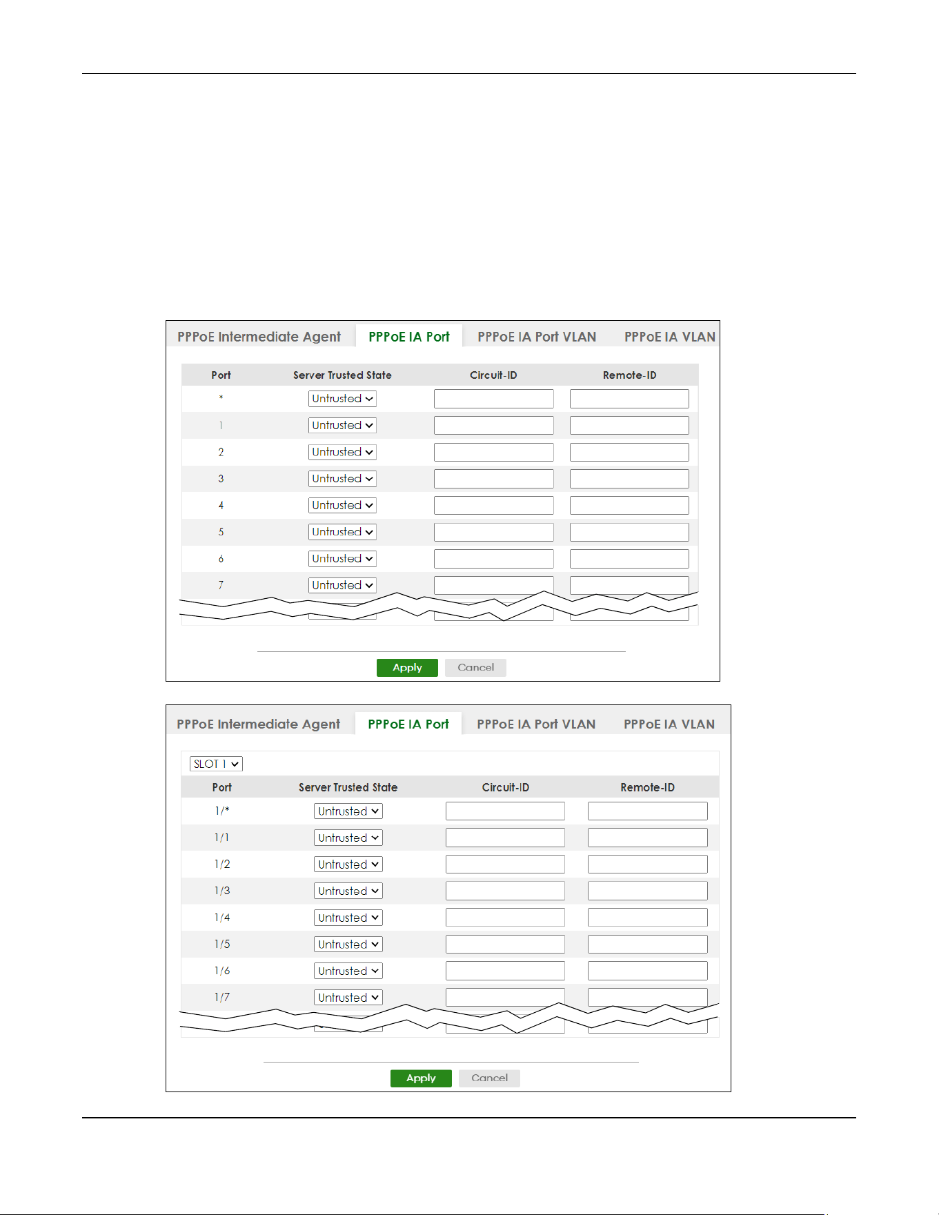
Chapter 48 PPPoE
XGS2220 Series User’s Guide
355
48.3 PPPoE IA Port
Use this screen to specify whether individual ports are trusted or untrusted ports and have the Switch
add extra information to PPPoE discovery packets from PPPoE clients on a per-port basis.
Note: The Switch will drop all PPPoE packets if you enable the PPPoE Intermediate Agent on
the Switch and there are no trusted ports.
Click the SWITCHING > PPPoE Intermediate Agent > PPPoE IA Port screen to display the screen as shown.
Figure 274 SWITCHING > PPPoE Intermediate Agent > PPPoE IA Port (Standalone Mode)
Figure 275 SWITCHING > PPPoE Intermediate Agent > PPPoE IA Port (Stacking Mode)

Chapter 48 PPPoE
XGS2220 Series User’s Guide
356
The following table describes the labels in this screen.
48.4 PPPoE IA Port VLAN
Use this screen to configure PPPoE IA settings that apply to a specific VLAN on a port.
Click SWITCHING > PPPoE Intermediate Agent > PPPoE IA Port VLAN to display the screen as shown.
Table 173 SWITCHING > PPPoE Intermediate Agent > PPPoE IA Port
LABEL DESCRIPTION
SLOT This field appears only in Stacking mode. Click the drop-down list to choose the slot number of
the Switch in a stack.
Port This field displays the port number. In Stacking mode, the first number represents the slot ID and
the second is the port number. Please note that the default stacking ports (the last four ports of
your Switch) cannot be configured. They are reserved for stacking only.
* Use this row to make the setting the same for all ports. Use this row first and then make
adjustments on a port-by-port basis.
Changes in this row are copied to all the ports as soon as you make them.
Server Trusted
State
Select whether this port is a trusted port (Trusted) or an untrusted port (Untrusted).
Trusted ports are uplink ports connected to PPPoE servers.
If a PADO (PPPoE Active Discovery Offer), PADS (PPPoE Active Discovery Session-confirmation),
or PADT (PPPoE Active Discovery Terminate) packet is sent from a PPPoE server and received on
a trusted port, the Switch forwards it to all other ports.
If a PADI or PADR packet is sent from a PPPoE client but received on a trusted port, the Switch
forwards it to other trusted ports.
Untrusted ports are downlink ports connected to subscribers.
If a PADI, PADR, or PADT packet is sent from a PPPoE client and received on an untrusted port,
the Switch adds a vendor-specific tag to the packet and then forwards it to the trusted ports.
The Switch discards PADO and PADS packets which are sent from a PPPoE server but received
on an untrusted port.
Circuit-ID Enter a string of up to 63 ASCII characters (except [ ? ], [ | ], [ ' ], [ " ], or [ , ]) that the Switch adds
into the Agent Circuit ID sub-option for PPPoE discovery packets received on this port. Spaces
are allowed.
The Circuit ID you configure for a specific VLAN on a port (in the SWITCHING > PPPoE
Intermediate Agent > PPPoE IA Port VLAN screen) has the highest priority.
Remote-ID Enter a string of up to 63 ASCII characters (except [ ? ], [ | ], [ ' ], [ " ], or [ , ]) that the Switch adds
into the Agent Remote ID sub-option for PPPoE discovery packets received on this port. Spaces
are allowed.
If you do not specify a string here or in the Remote-ID field for a VLAN on a port, the Switch
automatically uses the PPPoE client’s MAC address.
The Remote ID you configure for a specific VLAN on a port (in the SWITCHING > PPPoE
Intermediate Agent > PPPoE IA Port VLAN screen) has the highest priority.
Apply Click Apply to save your changes to the Switch’s run-time memory. The Switch loses these
changes if it is turned off or loses power, so use the Save link on the top navigation panel to save
your changes to the non-volatile memory when you are done configuring.
Cancel Click Cancel to begin configuring this screen afresh.
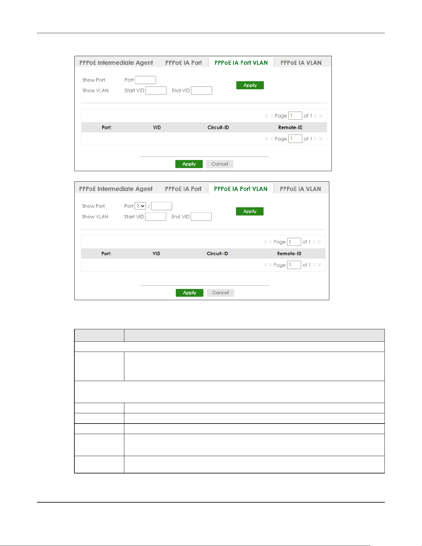
Chapter 48 PPPoE
XGS2220 Series User’s Guide
357
Figure 276 SWITCHING > PPPoE Intermediate Agent > PPPoE IA Port VLAN (Standalone Mode)
Figure 277 SWITCHING > PPPoE Intermediate Agent > PPPoE IA Port VLAN (Stacking Mode)
The following table describes the labels in this screen.
Table 174 SWITCHING > PPPoE Intermediate Agent > PPPoE IA Port VLAN
LABEL DESCRIPTION
Show Port
Port Enter a port number to show the PPPoE Intermediate Agent settings for the specified VLANs on
the port.
In Stacking mode, the first field is the slot ID and the second field is the port number.
Show VLAN
Use this section to specify the VLANs you want to configure in the section below.
Start VID Enter the lowest VLAN ID you want to configure in the section below.
End VID Enter the highest VLAN ID you want to configure in the section below.
Apply Click Apply to display the specified range of VLANs in the section below.
Port:
Slot / Port
This field displays the port number specified above.
In Stacking mode, it displays the slot ID and port number specified above.
VID This field displays the VLAN ID of each VLAN in the range specified above. If you configure the *
VLAN, the settings are applied to all VLANs.
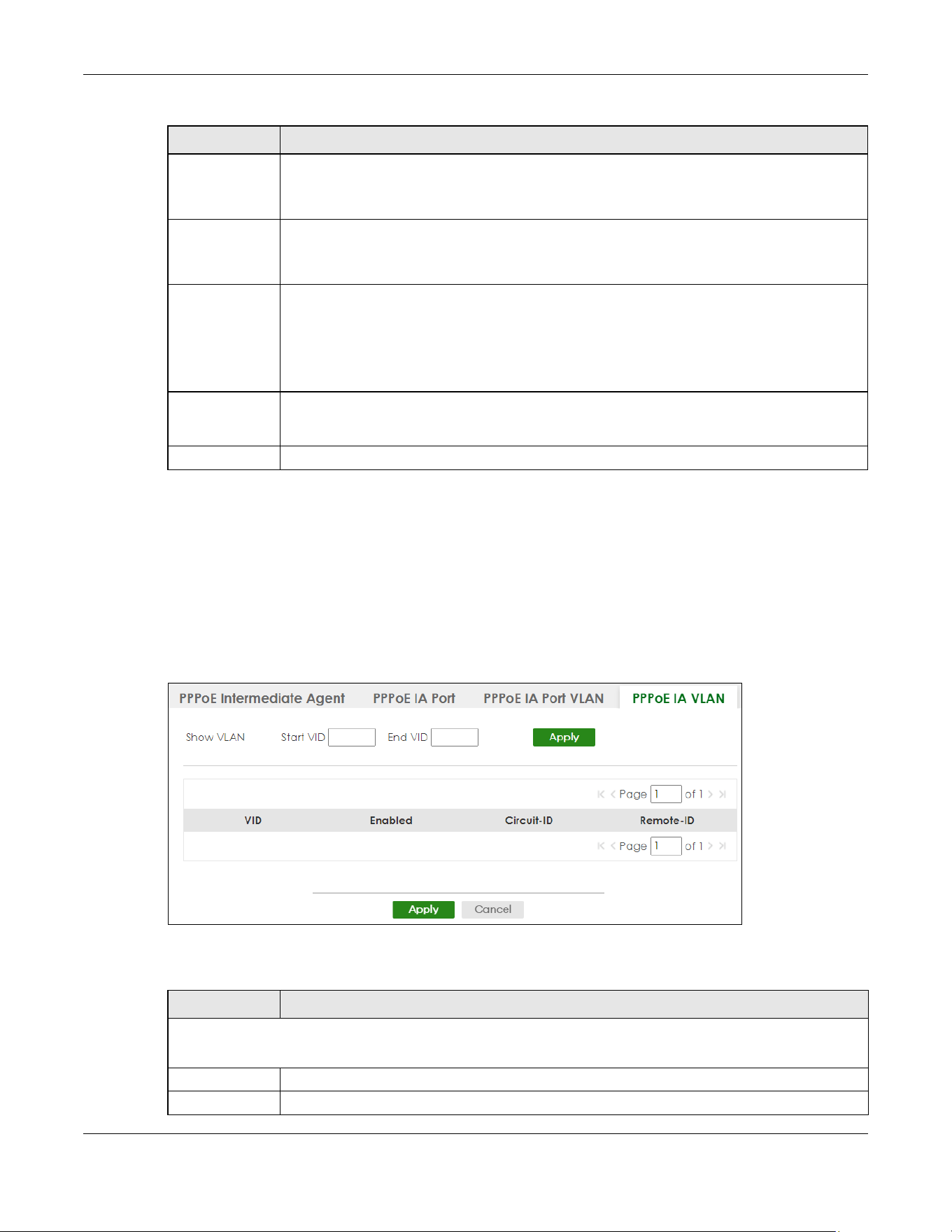
Chapter 48 PPPoE
XGS2220 Series User’s Guide
358
48.5 PPPoE IA VLAN
Use this screen to set whether the PPPoE Intermediate Agent is enabled on a VLAN and whether the
Switch appends the Circuit ID and/or Remote ID to PPPoE discovery packets from a specific VLAN.
Click SWITCHING > PPPoE Intermediate Agent > PPPoE IA VLAN to display the screen as shown.
Figure 278 SWITCHING > PPPoE Intermediate Agent > PPPoE IA VLAN
The following table describes the labels in this screen.
* Use this row to make the setting the same for all VLANs. Use this row first and then make
adjustments on a VLAN-by-VLAN basis.
Changes in this row are copied to all the VLANs as soon as you make them.
Circuit-ID Enter a string of up to 63 ASCII characters (except [ ? ], [ | ], [ ' ], [ " ], or [ , ]) that the Switch adds
into the Agent Circuit ID sub-option for this VLAN on the specified port. Spaces are allowed.
The Circuit ID you configure here has the highest priority.
Remote-ID Enter a string of up to 63 ASCII characters (except [ ? ], [ | ], [ ' ], [ " ], or [ , ]) that the Switch adds
into the Agent Remote ID sub-option for this VLAN on the specified port. Spaces are allowed.
If you do not specify a string here or in the Remote-ID field for a specific port, the Switch
automatically uses the PPPoE client’s MAC address.
The Remote ID you configure here has the highest priority.
Apply Click Apply to save your changes to the Switch’s run-time memory. The Switch loses these
changes if it is turned off or loses power, so use the Save link on the top navigation panel to save
your changes to the non-volatile memory when you are done configuring.
Cancel Click Cancel to begin configuring this screen afresh.
Table 174 SWITCHING > PPPoE Intermediate Agent > PPPoE IA Port VLAN (continued)
LABEL DESCRIPTION
Table 175 SWITCHING > PPPoE Intermediate Agent > PPPoE IA VLAN
LABEL DESCRIPTION
Show VLAN
Use this section to specify the VLANs you want to configure in the section below.
Start VID Enter the lowest VLAN ID you want to configure in the section below.
End VID Enter the highest VLAN ID you want to configure in the section below.

Chapter 48 PPPoE
XGS2220 Series User’s Guide
359
Apply Click Apply to display the specified range of VLANs in the section below.
VID This field displays the VLAN ID of each VLAN in the range specified above. If you configure the *
VLAN, the settings are applied to all VLANs.
* Use this row to make the setting the same for all VLANs. Use this row first and then make
adjustments on a VLAN-by-VLAN basis.
Changes in this row are copied to all the VLANs as soon as you make them.
Enabled Select this option to turn on the PPPoE Intermediate Agent on a VLAN.
Circuit-ID Select this option to make the Circuit ID settings for a specific VLAN take effect.
Remote-ID Select this option to make the Remote ID settings for a specific VLAN take effect.
Apply Click Apply to save your changes to the Switch’s run-time memory. The Switch loses these
changes if it is turned off or loses power, so use the Save link on the top navigation panel to save
your changes to the non-volatile memory when you are done configuring.
Cancel Click Cancel to begin configuring this screen afresh.
Table 175 SWITCHING > PPPoE Intermediate Agent > PPPoE IA VLAN (continued)
LABEL DESCRIPTION

Chapter 49 Differentiated Services
XGS2220 Series User’s Guide
360
CHAPTER 49
Differentiated Services
49.1 DiffServ Overview
This chapter shows you how to configure Differentiated Services (DiffServ) on the Switch.
Quality of Service (QoS) is used to prioritize source-to-destination traffic flows. All packets in the flow are
given the same priority. You can use CoS (class of service) to give different priorities to different packet
types.
DiffServ is a class of service (CoS) model that marks packets so that they receive specific per-hop
treatment at DiffServ-compliant network devices along the route based on the application types and
traffic flow. Packets are marked with DiffServ Code Points (DSCPs) indicating the level of service desired.
This allows the intermediary DiffServ-compliant network devices to handle the packets differently
depending on the code points without the need to negotiate paths or remember state information for
every flow. In addition, applications do not have to request a particular service or give advanced
notice of where the traffic is going.
49.1.1 What You Can Do
• Use the Diffserv screen (Section 49.1 on page 360) to activate DiffServ to apply marking rules or IEEE
802.1p priority mapping on the Switch.
• Use the DSCP Setting screen (Section 49.3.1 on page 363) to change the DSCP-IEEE 802.1p mapping.
49.1.2 What You Need to Know
Read on for concepts on Differentiated Services that can help you configure the screens in this chapter.
DSCP and Per-Hop Behavior
DiffServ defines a new DS (Differentiated Services) field to replace the Type of Service (ToS) field in the IP
header. The DS field contains a 6-bit DSCP field which can define up to 64 service levels and the
remaining 2 bits are defined as currently unused (CU). The following figure illustrates the DS field.
Figure 279 DiffServ: Differentiated Service Field
DSCP is backward compatible with the three precedence bits in the ToS octet so that non-DiffServ
compliant, ToS-enabled network device will not conflict with the DSCP mapping.
The DSCP value determines the PHB (Per-Hop Behavior), that each packet gets as it is forwarded across
the DiffServ network. Based on the marking rule different kinds of traffic can be marked for different
DSCP (6 bits) CU (2 bits)
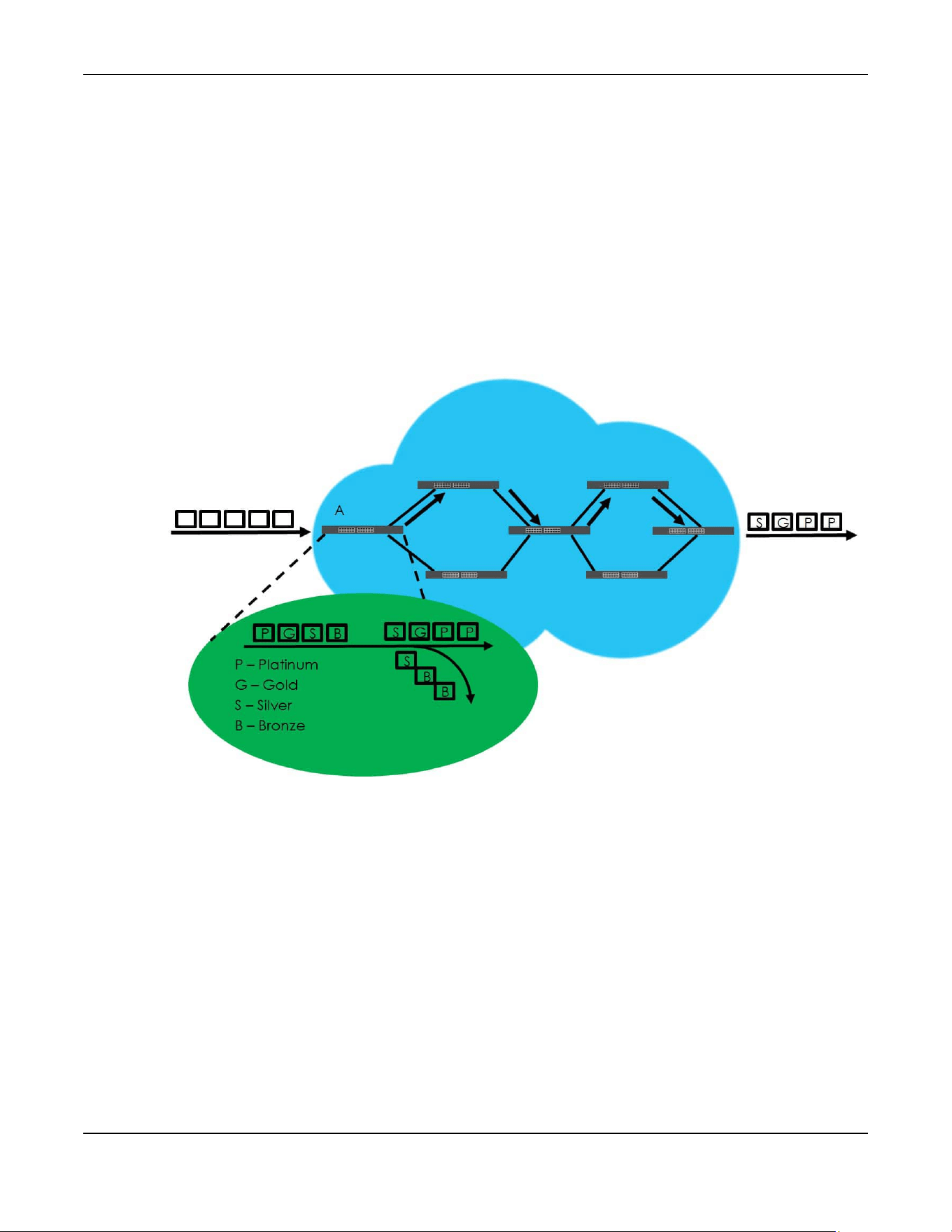
Chapter 49 Differentiated Services
XGS2220 Series User’s Guide
361
priorities of forwarding. Resources can then be allocated according to the DSCP values and the
configured policies.
DiffServ Network Example
The following figure depicts a DiffServ network consisting of a group of directly connected DiffServ-
compliant network devices. The boundary node (A in Figure 280) in a DiffServ network classifies (marks
with a DSCP value) the incoming packets into different traffic flows (Platinum, Gold, Silver, Bronze)
based on the configured marking rules. A network administrator can then apply various traffic policies to
the traffic flows. An example traffic policy, is to give higher drop precedence to one traffic flow over
others. In our example, packets in the Bronze traffic flow are more likely to be dropped when congestion
occurs than the packets in the Platinum traffic flow as they move across the DiffServ network.
Figure 280 DiffServ Network
49.2 Activating DiffServ
Activate DiffServ to apply marking rules or IEEE 802.1p priority mapping on the selected ports.
Click SWITCHING > QoS > Diffserv to display the screen as shown.
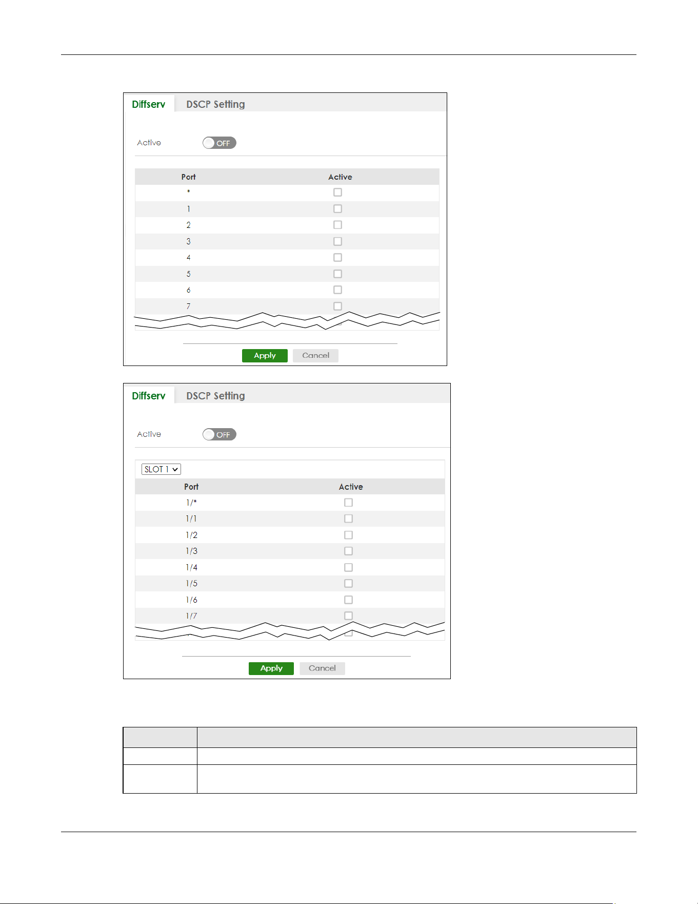
Chapter 49 Differentiated Services
XGS2220 Series User’s Guide
362
Figure 281 SWITCHING > QoS > Diffserv (Standalone Mode)
Figure 282 SWITCHING > QoS > Diffserv (Stacking Mode)
The following table describes the labels in this screen.
Table 176 SWITCHING > QoS > Diffserv
LABEL DESCRIPTION
Active Enable the switch button to enable Diffserv on the Switch.
Slot This field appears only in Stacking mode. Click the drop-down list to choose the slot number of the
Switch in a stack.

Chapter 49 Differentiated Services
XGS2220 Series User’s Guide
363
49.3 DSCP-to-IEEE 802.1p Priority Settings
You can configure the DSCP to IEEE 802.1p mapping to allow the Switch to prioritize all traffic based on
the incoming DSCP value according to the DiffServ to IEEE 802.1p mapping table.
The following table shows the default DSCP-to-IEEE802.1p mapping.
49.3.1 Configuring DSCP Settings
To change the DSCP-IEEE 802.1p mapping click SWITCHING > QoS > Diffserv > DSCP Setting to display the
screen as shown next.
Port This field displays the index number of a port on the Switch. In Stacking mode, the first number
represents the slot and the second the port number. * means all ports (on the same Switch).
* Settings in this row apply to all ports.
Use this row only if you want to make some settings the same for all ports. Use this row first to set the
common settings and then make adjustments on a port-by-port basis.
Changes in this row are copied to all the ports as soon as you make them.
Active Select Active to enable Diffserv on the port.
Apply Click Apply to save your changes to the Switch’s run-time memory. The Switch loses these
changes if it is turned off or loses power, so use the Save link on the top navigation panel to save
your changes to the non-volatile memory when you are done configuring.
Cancel Click Cancel to begin configuring this screen afresh.
Table 176 SWITCHING > QoS > Diffserv (continued)
LABEL DESCRIPTION
Table 177 Default DSCP-IEEE 802.1p Mapping
DSCP VALUE 0 – 7 8 – 15 16 – 23 24 – 31 32 – 39 40 – 47 48 – 55 56 – 63
IEEE 802.1p01234567

Chapter 49 Differentiated Services
XGS2220 Series User’s Guide
364
Figure 283 SWITCHING > QoS > Diffserv > DSCP Setting
The following table describes the labels in this screen.
Table 178 SWITCHING > QoS > Diffserv > DSCP Setting
LABEL DESCRIPTION
0 … 63 This is the DSCP classification identification number.
To set the IEEE 802.1p priority mapping, select the priority level from the drop-down list box.
Apply Click Apply to save your changes to the Switch’s run-time memory. The Switch loses these changes if it
is turned off or loses power, so use the Save link on the top navigation panel to save your changes to
the non-volatile memory when you are done configuring.
Cancel Click Cancel to begin configuring this screen afresh.

Chapter 50 Queuing Method
XGS2220 Series User’s Guide
365
CHAPTER 50
Queuing Method
50.1 Queuing Method Overview
This section introduces the queuing methods supported.
Queuing is used to help solve performance degradation when there is network congestion. Use the
Queuing Method screen to configure queuing algorithms for outgoing traffic. See also Priority Queue
Assignment in the SWITCHING > QoS > Priority Queue screen and 802.1p Priority in the PORT > Port Setup
screen for related information.
50.1.1 What You Can Do
Use the Queuing Method screen (Section 50.2 on page 366) to set priorities for the queues of the Switch.
This distributes bandwidth across the different traffic queues.
50.1.2 What You Need to Know
Queuing algorithms allow switches to maintain separate queues for packets from each individual
source or flow and prevent a source from monopolizing the bandwidth.
Strictly Priority Queuing
Strictly Priority Queuing (SPQ) services queues based on priority only. As traffic comes into the Switch,
traffic on the highest priority queue, Q7 is transmitted first. When that queue empties, traffic on the next
highest-priority queue, Q6 is transmitted until Q6 empties, and then traffic is transmitted on Q5 and so on.
If higher priority queues never empty, then traffic on lower priority queues never gets sent. SPQ does not
automatically adapt to changing network requirements.
Weighted Fair Queuing
Weighted Fair Queuing is used to guarantee each queue's minimum bandwidth based on its bandwidth
weight (portion) (the number you configure in the Weight field) when there is traffic congestion. WFQ is
activated only when a port has more traffic than it can handle. Queues with larger weights get more
guaranteed bandwidth than queues with smaller weights. This queuing mechanism is highly efficient in
that it divides any available bandwidth across the different traffic queues. By default, the weight for Q0
is 1, for Q1 is 2, for Q2 is 3, and so on.
Weighted Round Robin Scheduling (WRR)
Round Robin Scheduling services queues on a rotating basis and is activated only when a port has more
traffic than it can handle. A queue is given an amount of bandwidth irrespective of the incoming traffic
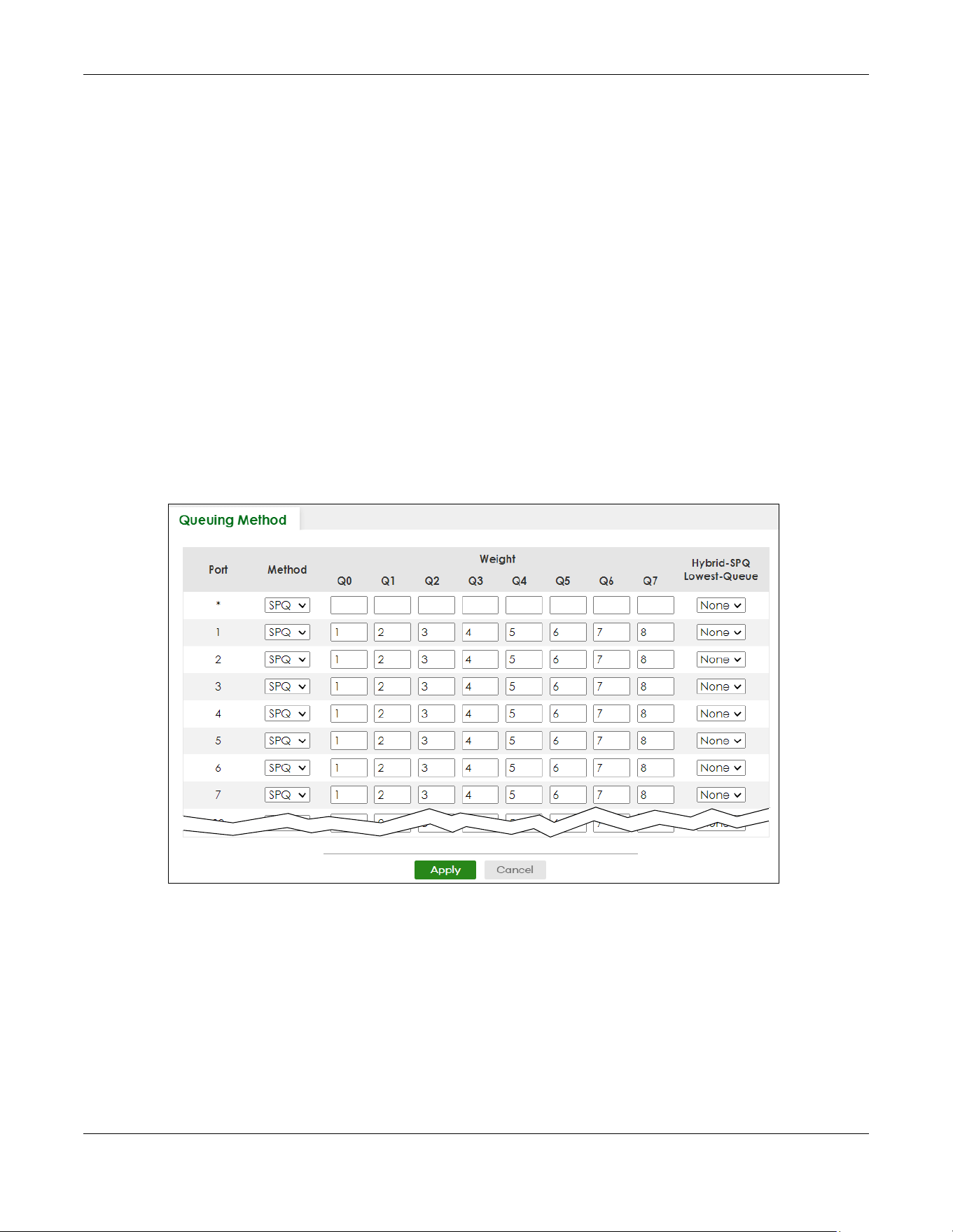
Chapter 50 Queuing Method
XGS2220 Series User’s Guide
366
on that port. This queue then moves to the back of the list. The next queue is given an equal amount of
bandwidth, and then moves to the end of the list; and so on, depending on the number of queues
being used. This works in a looping fashion until a queue is empty.
Weighted Round Robin Scheduling (WRR) uses the same algorithm as round robin scheduling, but
services queues based on their priority and queue weight (the number you configure in the queue
Weight field) rather than a fixed amount of bandwidth. WRR is activated only when a port has more
traffic than it can handle. Queues with larger weights get more service than queues with smaller
weights. This queuing mechanism is highly efficient in that it divides any available bandwidth across the
different traffic queues and returns to queues that have not yet emptied.
50.2 Configuring Queuing
Use this screen to set priorities for the queues of the Switch. This distributes bandwidth across the different
traffic queues.
Click SWITCHING > QoS > Queuing Method to display the screen as shown below.
Figure 284 SWITCHING > QoS > Queuing Method (Standalone Mode)
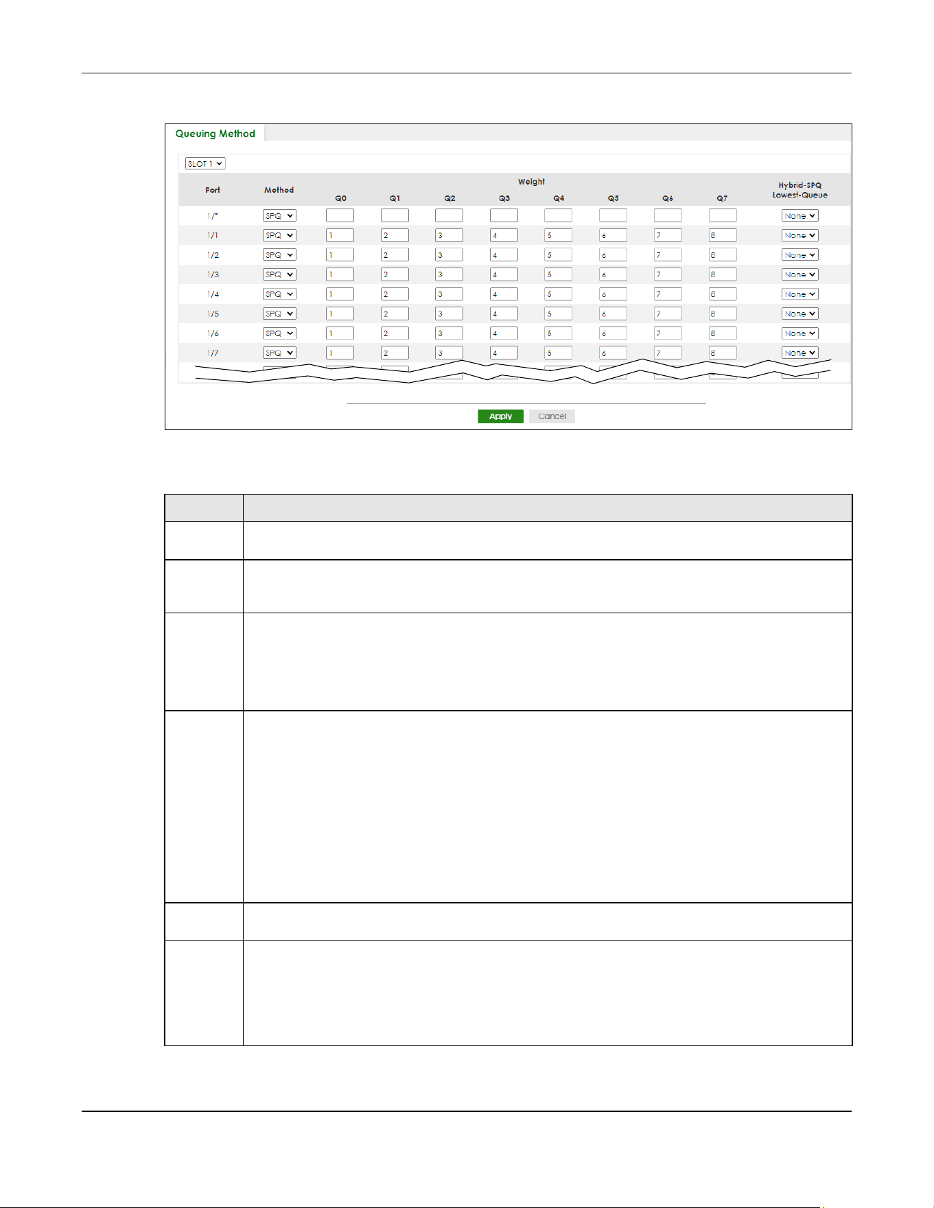
Chapter 50 Queuing Method
XGS2220 Series User’s Guide
367
Figure 285 SWITCHING > QoS > Queuing Method (Stacking Mode)
The following table describes the labels in this screen.
Table 179 SWITCHING > QoS > Queuing Method
LABEL DESCRIPTION
SLOT This field appears only in Stacking mode. Click the drop-down list to choose the slot number of the
Switch in a stack.
Port This field displays the port number. In Stacking mode, the first number represents the slot ID and the
second is the port number. Please note that the default stacking ports (the last four ports of your
Switch) cannot be configured. They are reserved for stacking only.
* Settings in this row apply to all ports.
Use this row only if you want to make some settings the same for all ports. Use this row first to set the
common settings and then make adjustments on a port-by-port basis.
Note: Changes in this row are copied to all the ports as soon as you make them.
Method Select SPQ (Strictly Priority Queuing), WFQ (Weighted Fair Queuing) or WRR (Weighted Round Robin).
Strictly Priority Queuing services queues based on priority only. When the highest priority queue
empties, traffic on the next highest-priority queue begins. Q7 has the highest priority and Q0 the
lowest.
Weighted Fair Queuing is used to guarantee each queue's minimum bandwidth based on their
bandwidth portion (weight) (the number you configure in the Weight field). Queues with larger
weights get more guaranteed bandwidth than queues with smaller weights.
Weighted Round Robin Scheduling services queues on a rotating basis based on their queue weight
(the number you configure in the queue Weight field). Queues with larger weights get more service
than queues with smaller weights.
Weight When you select WFQ or WRR, enter the queue weight here. Bandwidth is divided across the different
traffic queues according to their weights.
Hybrid-SPQ
Lowest-
Queue
This field is applicable only when you select WFQ or WRR.
Select a queue (Q0 to Q7) to have the Switch use SPQ to service the subsequent queues after and
including the specified queue for the port. For example, if you select Q5, the Switch services traffic on
Q5, Q6 and Q7 using SPQ.
Select None to always use WFQ or WRR for the port.

Chapter 50 Queuing Method
XGS2220 Series User’s Guide
368
Apply Click Apply to save your changes to the Switch’s run-time memory. The Switch loses these changes if
it is turned off or loses power, so use the Save link on the top navigation panel to save your changes to
the non-volatile memory when you are done configuring.
Cancel Click Cancel to begin configuring this screen afresh.
Table 179 SWITCHING > QoS > Queuing Method (continued)
LABEL DESCRIPTION

Chapter 51 Priority Queue
XGS2220 Series User’s Guide
369
CHAPTER 51
Priority Queue
51.1 Priority Queue Overview
IEEE 802.1p defines up to eight separate traffic types by inserting a tag into a MAC-layer frame that
contains bits to define class of service. Frames without an explicit priority tag are given the default
priority of the ingress port. Use this screen to configure the priority level-to-physical queue mapping. The
Switch has eight physical queues that you can map to the eight priority levels.
On the Switch, traffic assigned to higher index queues gets through faster while traffic in lower index
queues is dropped if the network is congested.
51.1.1 What You Can Do
Use the Priority Queue screen (Section 51.2 on page 369) to configure the priority level-to-physical
queue mapping.
51.2 Assign Priority Queue
Use this screen to assign priority level to each queue.
Click SWITCHING > QoS > Priority Queue to open this screen.
Figure 286 SWITCHING > QoS > Priority Queue

Chapter 51 Priority Queue
XGS2220 Series User’s Guide
370
The following table describes the related labels in this screen.
Table 180 SWITCHING > QoS > Priority Queue
LABEL DESCRIPTION
Priority Queue Assignment
The following descriptions are based on the traffic types defined in the IEEE 802.1d standard (which incorporates
the 802.1p). To map a priority level to a physical queue, select a physical queue from the drop-down menu on the
right.
Priority 7 Typically used for network control traffic such as router configuration messages.
Priority 6 Typically used for voice traffic that is especially sensitive to jitter (jitter is the variations in delay).
Priority 5 Typically used for video that consumes high bandwidth and is sensitive to jitter.
Priority 4 Typically used for controlled load, latency-sensitive traffic such as SNA (Systems Network
Architecture) transactions.
Priority 3 Typically used for “excellent effort” or better than best effort and would include important business
traffic that can tolerate some delay.
Priority 2 This is for “spare bandwidth”.
Priority 1 This is typically used for non-critical “background” traffic such as bulk transfers that are allowed but
that should not affect other applications and users.
Priority 0 Typically used for best-effort traffic.
Apply Click Apply to save your changes to the Switch’s run-time memory. The Switch loses these changes
if it is turned off or loses power, so use the Save link on the top navigation panel to save your
changes to the non-volatile memory when you are done configuring.
Cancel Click Cancel to reset the fields.

Chapter 52 Bandwidth Control
XGS2220 Series User’s Guide
371
CHAPTER 52
Bandwidth Control
52.1 Bandwidth Control Overview
This chapter shows you how you can cap the maximum bandwidth using the Bandwidth Control screen.
Bandwidth control means defining a maximum allowable bandwidth for incoming and/or out-going
traffic flows on a port.
52.1.1 What You Can Do
Use the Bandwidth Control screen (Section 52.2 on page 371) to limit the bandwidth for traffic going
through the Switch.
52.1.2 CIR and PIR
The Committed Information Rate (CIR) is the guaranteed bandwidth for the incoming traffic flow on a
port. The Peak Information Rate (PIR) is the maximum bandwidth allowed for the incoming traffic flow on
a port when there is no network congestion.
The CIR and PIR should be set for all ports that use the same uplink bandwidth. If the CIR is reached,
packets are sent at the rate up to the PIR. When network congestion occurs, packets through the
ingress port exceeding the CIR will be marked for drop.
52.2 Bandwidth Control Setup
Click SWITCHING > QoS > Bandwidth Control in the navigation panel to bring up the screen as shown
next.
Note: The CIR should be less than the PIR.
Note: The sum of CIRs cannot be greater than or equal to the uplink bandwidth.

Chapter 52 Bandwidth Control
XGS2220 Series User’s Guide
372
Figure 287 SWITCHING > QoS > Bandwidth Control (Standalone mode)
Figure 288 SWITCHING > QoS > Bandwidth Control (Stacking Mode)
Chapter 52 Bandwidth Control
XGS2220 Series User’s Guide
373
The following table describes the related labels in this screen.
Table 181 SWITCHING > QoS > Bandwidth Control
LABEL DESCRIPTION
Active Enable the switch button to enable bandwidth control on the Switch.
SLOT This field appears only in Stacking mode. Click the drop-down list to choose the slot number of the
Switch in a stack.
Port This field displays the port number. In Stacking mode, the first number represents the slot ID and the
second is the port number. Please note that the default stacking ports (the last four ports of your
Switch) cannot be configured. They are reserved for stacking only.
* Settings in this row apply to all ports.
Use this row only if you want to make some settings the same for all ports. Use this row first to set the
common settings and then make adjustments on a port-by-port basis.
Note: Changes in this row are copied to all the ports as soon as you make them.
Active Select this check box to activate ingress rate limits on this port.
Ingress Rate Specify the maximum bandwidth allowed in kilobits per second (Kbps) for the incoming traffic flow
on a port.
Note: Ingress rate bandwidth control applies to layer 2 traffic only.
Active Select this check box to activate egress rate limits on this port.
Egress Rate Specify the maximum bandwidth allowed in kilobits per second (Kbps) for the out-going traffic
flow on a port.
Apply Click Apply to save your changes to the Switch’s run-time memory. The Switch loses these changes
if it is turned off or loses power, so use the Save link on the top navigation panel to save your
changes to the non-volatile memory when you are done configuring.
Cancel Click Cancel to reset the fields.
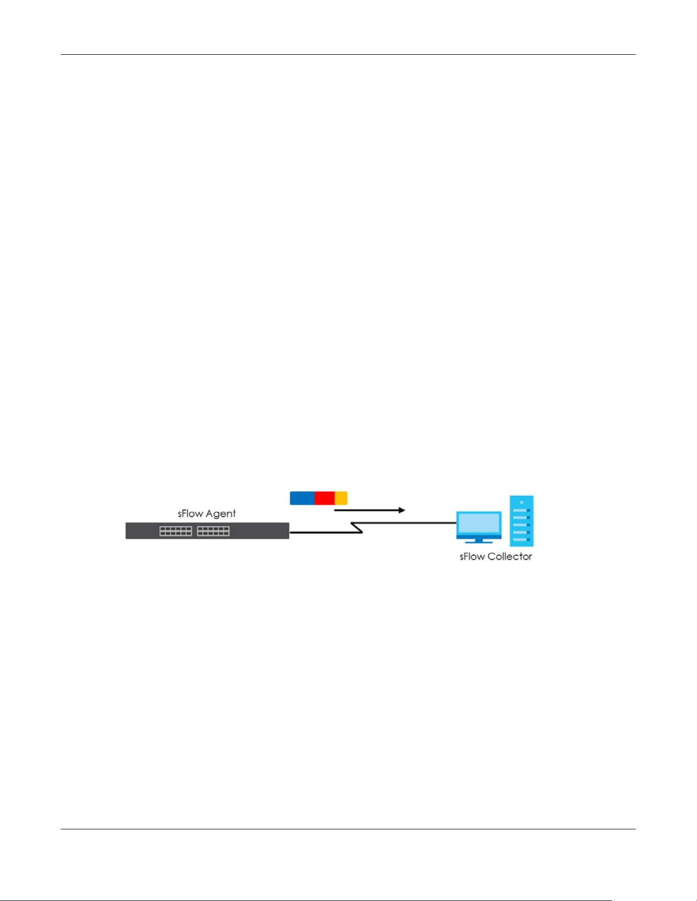
Chapter 53 sFlow
XGS2220 Series User’s Guide
374
CHAPTER 53
sFlow
This chapter shows you how to configure sFlow to have the Switch monitor traffic in a network and send
information to an sFlow collector for analysis.
53.1 sFlow Overview
sFlow (RFC 3176) is a standard technology for monitoring switched networks. An sFlow agent embedded
on a switch or router gets sample data and packet statistics from traffic forwarded through its ports. The
sFlow agent then creates sFlow data and sends it to an sFlow collector. The sFlow collector is a server
that collects and analyzes sFlow datagram. An sFlow datagram includes packet header, input and
output interface, sampling process parameters and forwarding information.
sFlow minimizes impact on CPU load of the Switch as it analyzes sample data only. sFlow can
continuously monitor network traffic and create reports for network performance analysis and
troubleshooting. For example, you can use it to know which IP address or which type of traffic caused
network congestion.
Figure 289 sFlow Application
53.2 sFlow Port Configuration
Click SWITCHING > sFlow in the navigation panel to display the screen as shown.
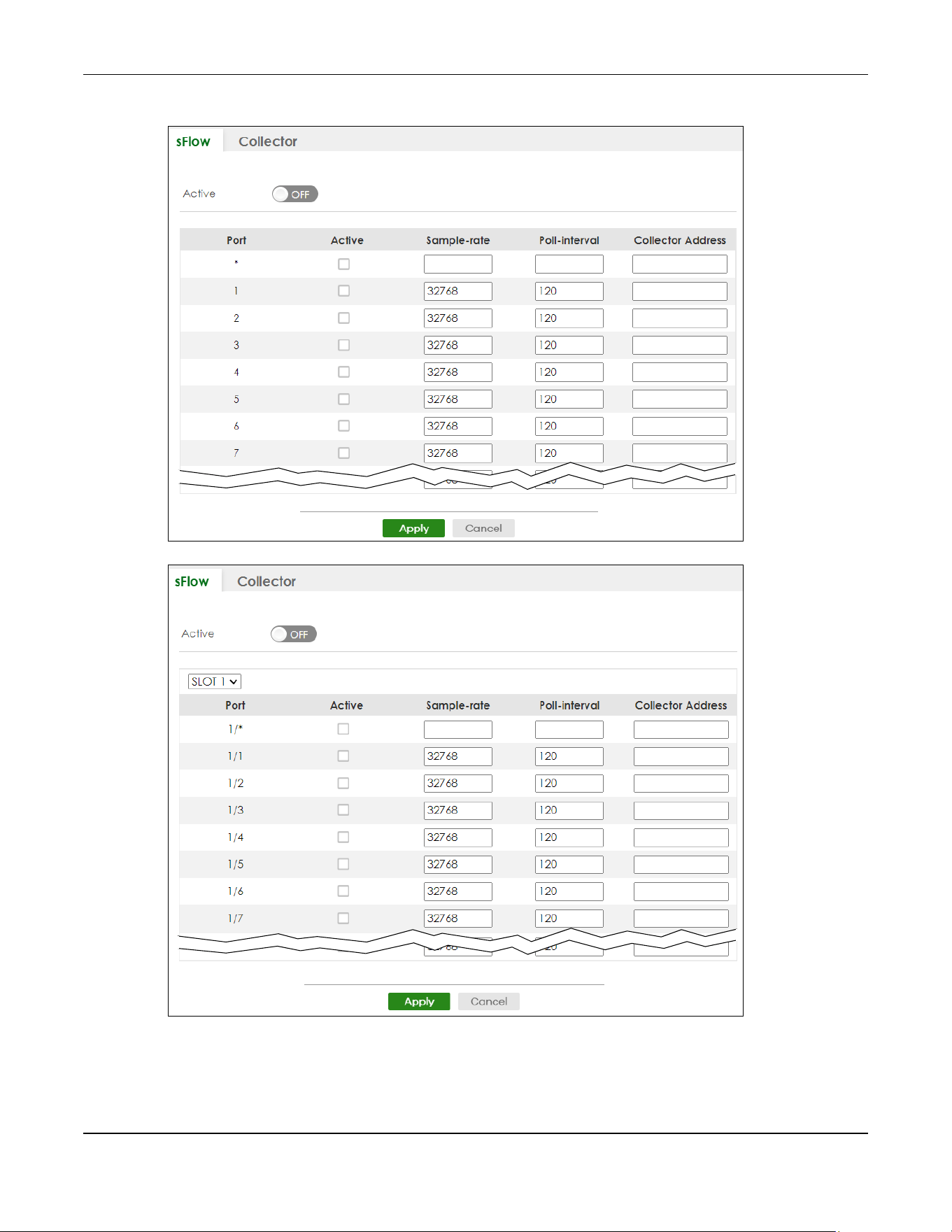
Chapter 53 sFlow
XGS2220 Series User’s Guide
375
Figure 290 SWITCHING > sFlow (Standalone Mode)
Figure 291 SWITCHING > sFlow (Stacking Mode)

Chapter 53 sFlow
XGS2220 Series User’s Guide
376
The following table describes the labels in this screen.
53.3 sFlow Collector Configuration
Click SWITCHING > sFlow > Collector to display the screen as shown. You may want to configure more
than one collector if the traffic load to be monitored is more than one collector can manage.
Note: You can configure up to four sFlow collectors in this screen.
Figure 292 SWITCHING > sFlow > Collector
Table 182 SWITCHING > sFlow
LABEL DESCRIPTION
Active Enable the switch button to enable the sFlow agent on the Switch.
SLOT This field appears only in Stacking mode. Click the drop-down list to choose the slot number of
the Switch in a stack.
Port This field displays the port number. In Stacking mode, the first number represents the slot ID and
the second is the port number. Please note that the default stacking ports (the last four ports of
your Switch) cannot be configured. They are reserved for stacking only.
* Settings in this row apply to all ports.
Use this row only if you want to make some settings the same for all ports. Use this row first to set
the common settings and then make adjustments on a port-by-port basis.
Note: Changes in this row are copied to all the ports as soon as you make them.
Active Select this to allow the Switch to monitor traffic on this port and generate and send sFlow
datagram to the specified collector.
Sample-rate Enter a number (N) from 256 to 65535. The Switch captures every one out of N packets for this
port and creates sFlow datagram.
Poll-interval Specify a time interval (from 20 to 120 in seconds) the Switch waits before sending the sFlow
datagram and packet counters for this port to the collector.
Collector
Address
Enter the IP address of the sFlow collector.
Note: You must have the sFlow collector already configured in the SWITCHING > sFlow
> Collector screen. The sFlow collector does not need to be in the same subnet
as the Switch, but it must be accessible from the Switch.
Note: Configure UDP port 6343 (the default) on a NAT router to allow port forwarding
if the collector is behind a NAT router. Configure a firewall rule for UDP port 6343
(the default) to allow incoming traffic if the collector is behind a firewall.
Apply Click Apply to save your changes to the Switch’s run-time memory. The Switch loses these
changes if it is turned off or loses power, so use the Save link on the top navigation panel to save
your changes to the non-volatile memory when you are done configuring.
Cancel Click Cancel to begin configuring this screen afresh.

Chapter 53 sFlow
XGS2220 Series User’s Guide
377
The following table describes the labels in this screen.
53.3.1 Add/Edit sFlow Collector
Click Add/Edit, or select an entry and click Add/Edit in the SWITHCING > sFlow > Collector screen to
display this screen.
Figure 293 SWITCHING > sFlow > Collector > Add/Edit
The following table describes the labels in this screen.
Table 183 SWITCHING > sFlow > Collector
LABEL DESCRIPTION
Index This field displays the index number of this entry.
Collector
Address
This field displays IP address of the sFlow collector.
UDP Port This field displays port number the Switch uses to send sFlow datagram to the collector.
Select an entry’s check box to select a specific entry. Otherwise, select the check box in the
table heading row to select all entries.
Add/Edit Click Add/Edit to add a new entry or edit a selected one.
Delete Click Delete to remove the selected entries.
Table 184 SWITCHING > sFlow > Collector > Add/Edit
LABEL DESCRIPTION
Collector
Address
Enter the IP address of the sFlow collector.
UDP Port Enter a UDP port number the Switch uses to send sFlow datagram to the collector. If you change
the port here, make sure you change it on the collector, too. The default port is 6343.
Apply Click Apply to save your changes to the Switch’s run-time memory. The Switch loses these
changes if it is turned off or loses power, so use the Save link on the top navigation panel to save
your changes to the non-volatile memory when you are done configuring.
Clear Click Clear to clear the fields to the factory defaults.
Cancel Click Cancel to not save the configuration you make and return to the last screen.

XGS2220 Series User’s Guide
378
CHAPTER 54
Spanning Tree Protocol
54.1 Spanning Tree Protocol Overview
The Switch supports Spanning Tree Protocol (STP), Rapid Spanning Tree Protocol (RSTP) and Multiple
Spanning Tree Protocol (MSTP) as defined in the following standards.
• IEEE 802.1D Spanning Tree Protocol
• IEEE 802.1w Rapid Spanning Tree Protocol
• IEEE 802.1s Multiple Spanning Tree Protocol
The Switch also allows you to set up multiple STP configurations (or trees). Ports can then be assigned to
the trees.
54.1.1 What You Can Do
• Use the Spanning Tree Protocol Status screen (Section 54.2 on page 381) to view the STP status in the
different STP modes (RSTP, MRSTP or MSTP) you can configure on the Switch.
• Use the Spanning Tree Setup screen (Section 54.3 on page 382) to activate one of the STP modes on
the Switch.
• Use the Rapid Spanning Tree Protocol Status screen (Section 54.4 on page 385) to view the RSTP status.
• Use the Rapid Spanning Tree Protocol screen (Section 54.5 on page 387) to configure RSTP settings.
• Use the Multiple Rapid Spanning Tree Protocol Status screen (Section 54.6 on page 391) to view the
MRSTP status.
• Use the Multiple Rapid Spanning Tree Protocol screen (Section 54.7 on page 393) to configure MRSTP.
• Use the Multiple Spanning Tree Protocol Status screen (Section 54.8 on page 397) to view the MSTP
status.
• Use the Multiple Spanning Tree Protocol screen (Section 54.9 on page 401) to configure MSTP.
• Use the Multiple Spanning Tree Protocol Port Setup screen (Section 54.10 on page 405) to configure
MSTP ports.
54.1.2 What You Need to Know
Read on for concepts on STP that can help you configure the screens in this chapter.
(Rapid) Spanning Tree Protocol
(R)STP detects and breaks network loops and provides backup links between switches, bridges or
routers. It allows a switch to interact with other (R)STP-compliant switches in your network to ensure that
only one path exists between any two stations on the network.
The Switch uses IEEE 802.1w RSTP (Rapid Spanning Tree Protocol) that allows faster convergence of the

Chapter 54 Spanning Tree Protocol
XGS2220 Series User’s Guide
379
spanning tree than STP (while also being backwards compatible with STP-only aware bridges). In RSTP,
topology change information is directly propagated throughout the network from the device that
generates the topology change. In STP, a longer delay is required as the device that causes a topology
change first notifies the root bridge that then notifies the network. Both RSTP and STP flush unwanted
learned addresses from the filtering database. In RSTP, the port states are Discarding, Learning, and
Forwarding.
Note: In this user’s guide, “STP” refers to both STP and RSTP.
STP Terminology
The root bridge is the base of the spanning tree.
Path cost is the cost of transmitting a frame onto a LAN through that port. The recommended cost is
assigned according to the speed of the link to which a port is attached. The slower the media, the
higher the cost.
On each bridge, the root port is the port through which this bridge communicates with the root. It is the
port on this switch with the lowest path cost to the root (the root path cost). If there is no root port, then
this switch has been accepted as the root bridge of the spanning tree network.
For each LAN segment, a designated bridge is selected. This bridge has the lowest cost to the root
among the bridges connected to the LAN.
How STP Works
After a bridge determines the lowest cost-spanning tree with STP, it enables the root port and the ports
that are the designated ports for connected LANs, and disables all other ports that participate in STP.
Network packets are therefore only forwarded between enabled ports, eliminating any possible
network loops.
STP-aware switches exchange Bridge Protocol Data Units (BPDUs) periodically. When the bridged LAN
topology changes, a new spanning tree is constructed.
Once a stable network topology has been established, all bridges listen for Hello BPDUs (Bridge Protocol
Data Units) transmitted from the root bridge. If a bridge does not get a Hello BPDU after a predefined
interval (Max Age), the bridge assumes that the link to the root bridge is down. This bridge then initiates
negotiations with other bridges to reconfigure the network to re-establish a valid network topology.
STP Port States
STP assigns five port states to eliminate packet looping. A bridge port is not allowed to go directly from
Table 185 STP Path Costs
LINK SPEED RECOMMENDED VALUE RECOMMENDED RANGE ALLOWED RANGE
Path Cost 4 Mbps 250 100 to 1000 1 to 65535
Path Cost 10 Mbps 100 50 to 600 1 to 65535
Path Cost 16 Mbps 62 40 to 400 1 to 65535
Path Cost 100 Mbps 19 10 to 60 1 to 65535
Path Cost 1 Gbps 4 3 to 10 1 to 65535
Path Cost 10 Gbps 2 1 to 5 1 to 65535

Chapter 54 Spanning Tree Protocol
XGS2220 Series User’s Guide
380
blocking state to forwarding state so as to eliminate transient loops.
Multiple RSTP
MRSTP (Multiple RSTP) is Zyxel’s proprietary feature that is compatible with RSTP and STP. With MRSTP, you
can have more than one spanning tree on your Switch and assign ports to each tree. Each spanning
tree operates independently with its own bridge information.
In the following example, there are two RSTP instances (MRSTP 1 and MRSTP2) on switch A.
To set up MRSTP, activate MRSTP on the Switch and specify which ports belong to which spanning tree.
Note: Each port can belong to one STP tree only.
Figure 294 MRSTP Network Example
Multiple STP
Multiple Spanning Tree Protocol (IEEE 802.1s) is backward compatible with STP/RSTP and addresses the
limitations of existing spanning tree protocols (STP and RSTP) in networks to include the following
features:
• One Common and Internal Spanning Tree (CIST) that represents the entire network’s connectivity.
• Grouping of multiple bridges (or switching devices) into regions that appear as one single bridge on
the network.
• A VLAN can be mapped to a specific Multiple Spanning Tree Instance (MSTI). MSTI allows multiple
VLANs to use the same spanning tree.
• Load-balancing is possible as traffic from different VLANs can use distinct paths in a region.
Table 186 STP Port States
PORT STATE DESCRIPTION
Disabled STP is disabled (default).
Blocking Only configuration and management BPDUs are received and processed.
Listening All BPDUs are received and processed.
Note: The listening state does NOT exist in RSTP.
Learning All BPDUs are received and processed. Information frames are submitted to the learning process
but not forwarded.
Forwarding All BPDUs are received and processed. All information frames are received and forwarded.
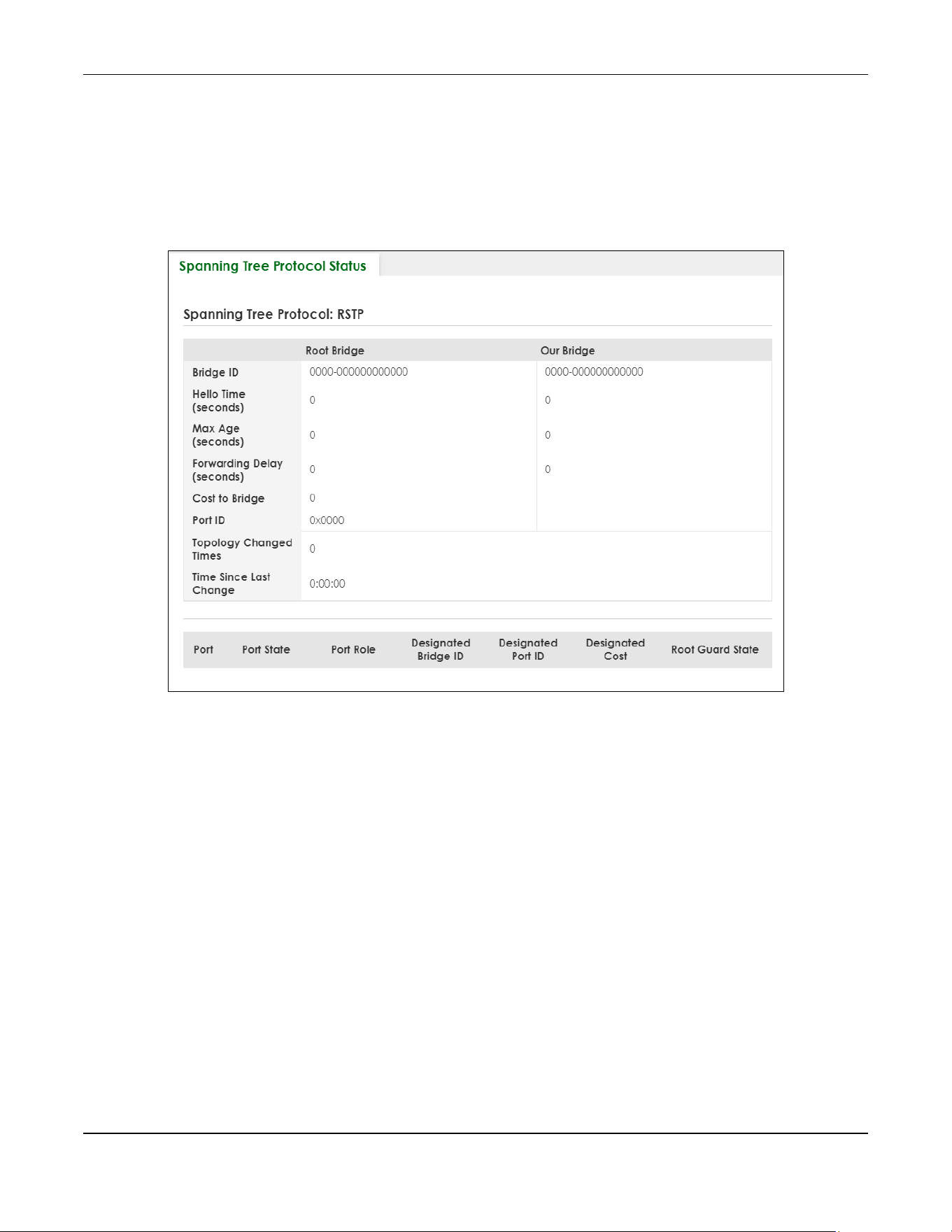
Chapter 54 Spanning Tree Protocol
XGS2220 Series User’s Guide
381
54.2 Spanning Tree Protocol Status
The Spanning Tree Protocol status screen changes depending on what standard you choose to
implement on your network. Click SWITCHING > Spanning Tree Protocol > Spanning Tree Protocol Status
to see the screen as shown.
Figure 295 SWITCHING > Spanning Tree Protocol > Spanning Tree Protocol Status (Standalone Mode)
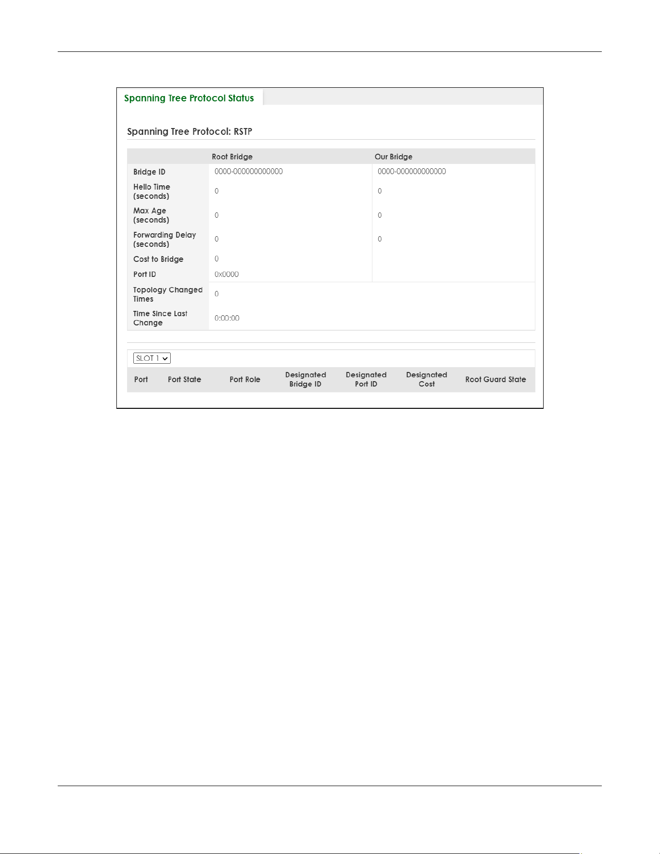
Chapter 54 Spanning Tree Protocol
XGS2220 Series User’s Guide
382
Figure 296 SWITCHING > Spanning Tree Protocol > Spanning Tree Protocol Status (Stacking Mode)
This screen differs depending on which STP mode (RSTP, MRSTP or MSTP) you configure on the Switch. This
screen is described in detail in the section (Section 54.4 on page 385, Section 54.6 on page 391, and
Section 54.8 on page 397) that follows the configuration section for each STP mode. Use the SWITCHING
> Spanning Tree Protocol > Spanning Tree Setup screen to activate one of the STP standards on the
Switch.
54.3 Spanning Tree Setup
There are three Auto path-cost Modes (see Table 190 on page 384). Choose the Auto Path-cost Mode
according to the device average link speeds in the STP network.
If most of your devices support high link speed, you should select Long or User-defined mode. The path
cost of link speed slower than 10 Mbps can be set to 2000000, and the path cost of link speed faster than
10 Gbps can be set to 200. This way, the path costs can better reflect actual link speeds with a wider
range (32 bits) of path cost values. If the link speeds within the system are averagely smaller than 1
Gbps, you should select Short mode since Short mode have path cost values more detailed defined for
link speeds under1 Gbps.
The path cost values are described in the following tables.

Chapter 54 Spanning Tree Protocol
XGS2220 Series User’s Guide
383
The Switch defines the following Short mode path costs.
The Switch defines the following Long mode path costs.
If you do not configure the auto path cost values for User-defined mode, the Switch uses the following
default values.
Use the this screen to activate one of the STP modes on the Switch. Click SWITCHING > Spanning Tree
Protocol > Spanning Tree Setup to display the screen as shown.
Table 187 Auto Path Cost Mode: Short
LINK SPEED AUTO PATH COST VALUE
Up to 4 Mbps 250
Up to 10 Mbps 100
Up to 16 Mbps 62
Up to 100 Mbps 19
Up to 1 Gbps 4
Up to 10 Gbps 2
More than 10 Gbps 1
Table 188 Auto Path Cost Mode: Long
LINK SPEED AUTO PATH COST VALUE
Up to 10 Mbps 2000000
Up to 100 Mbps 200000
Up to 1 Gbps 20000
Up to 2.5 Gbps 8000
Up to 5 Gbps 4000
Up to 10 Gbps 2000
More than 10 Gbps 200
Table 189 Auto Path Cost Mode: User-defined
LINK SPEED AUTO PATH COST VALUE
Up to 10 Mbps 2000000
Up to 100 Mbps 200000
Up to 1 Gbps 20000
Up to 2.5 Gbps 8000
Up to 5 Gbps 4000
More than 5 Gbps 2000
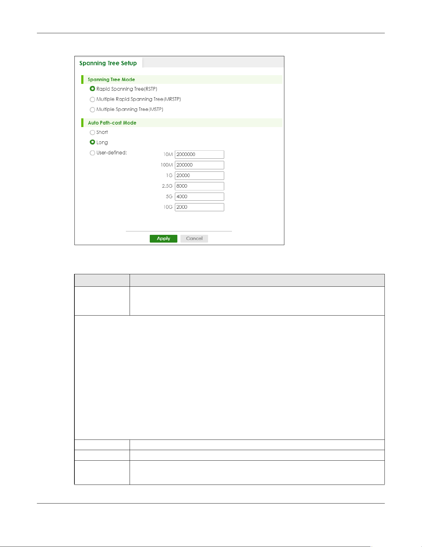
Chapter 54 Spanning Tree Protocol
XGS2220 Series User’s Guide
384
Figure 297 SWITCHING > Spanning Tree Protocol > Spanning Tree Setup
The following table describes the labels in this screen.
Table 190 SWITCHING > Spanning Tree Protocol > Spanning Tree Setup
LABEL DESCRIPTION
Spanning Tree
Mode
You can activate one of the STP modes on the Switch.
Select Rapid Spanning Tree (RSTP), Multiple Rapid Spanning Tree (MRSTP) or Multiple Spanning
Tree (MSTP).
Auto Path-cost Mode
Auto Path-cost Mode allows you to have the Switch automatically set the path cost for each port according to
their link speed. The Switch uses the path costs to determine the best path to the root bridge in a spanning tree.
There are three Auto Path-cost Modes that supports different path cost lengths:
• Short (16-bit)
• Long (32-bit)
• User-defined (32-bit).
The auto path cost values of each mode are described in Section 54.3 on page 382.
Note: It is recommended to use the same Auto Path-cost Mode on all switches within the spanning
tree network system.
To use the auto path-cost feature, select the Auto Path-cost mode (Short, Long, User-defined), set a port’s Path Cost
(in the SWITCHING > Spanning Tree Protocol > RSTP, MRSTP, and MSTP screens) to “0”. The Switch will automatically
set the port’s path cost to the auto path cost value defined by the Auto Path-cost Mode you select.
Short Select this mode if you want to use the 16-bit auto path cost values the Switch defines.
Long Select this mode if you want to use the 32-bit auto path cost values the Switch defines.
User-defined Select this mode to manually set the auto path costs for each link speed. Enter the path cost
value for each link speed. The range is from 1 – 2000000. It is recommended to assign this value
according to link speeds. The slower the speed, the higher the cost.
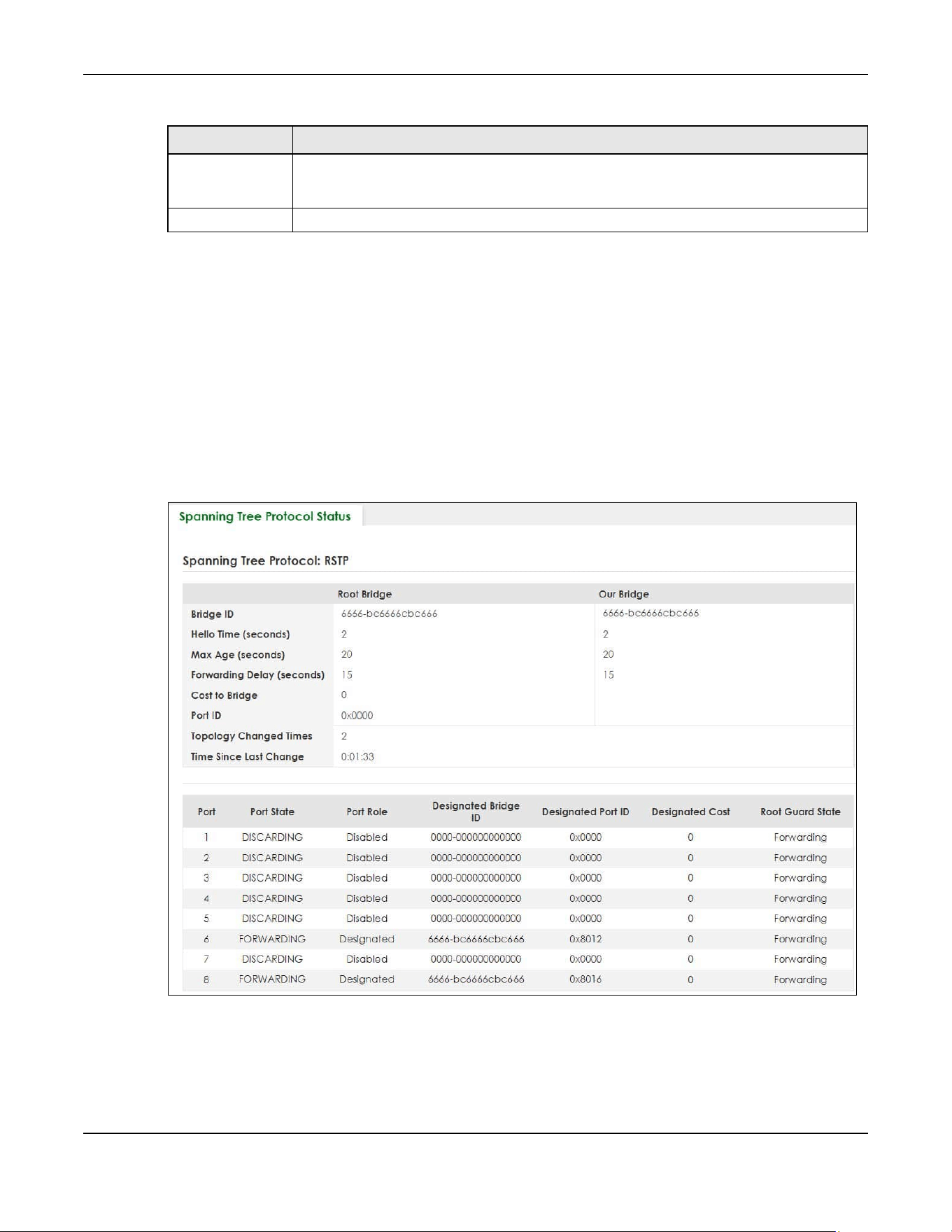
Chapter 54 Spanning Tree Protocol
XGS2220 Series User’s Guide
385
54.4 Rapid Spanning Tree Protocol Status
The Spanning Tree Protocol status screen changes depending on what standard you choose to
implement on your network. Click SWITCHING > Spanning Tree Protocol > Spanning Tree Protocol Status
in the navigation panel to display the status screen as shown next. See Section 54.1 on page 378 for
more information on RSTP.
Note: This screen is only available after you activate RSTP on the Switch.
Figure 298 SWITCHING > Spanning Tree Protocol > Spanning Tree Protocol Status: RSTP (Standalone
Mode)
Apply Click Apply to save your changes to the Switch’s run-time memory. The Switch loses these
changes if it is turned off or loses power, so use the Save link on the top navigation panel to
save your changes to the non-volatile memory when you are done configuring.
Cancel Click Cancel to begin configuring this screen afresh.
Table 190 SWITCHING > Spanning Tree Protocol > Spanning Tree Setup (continued)
LABEL DESCRIPTION
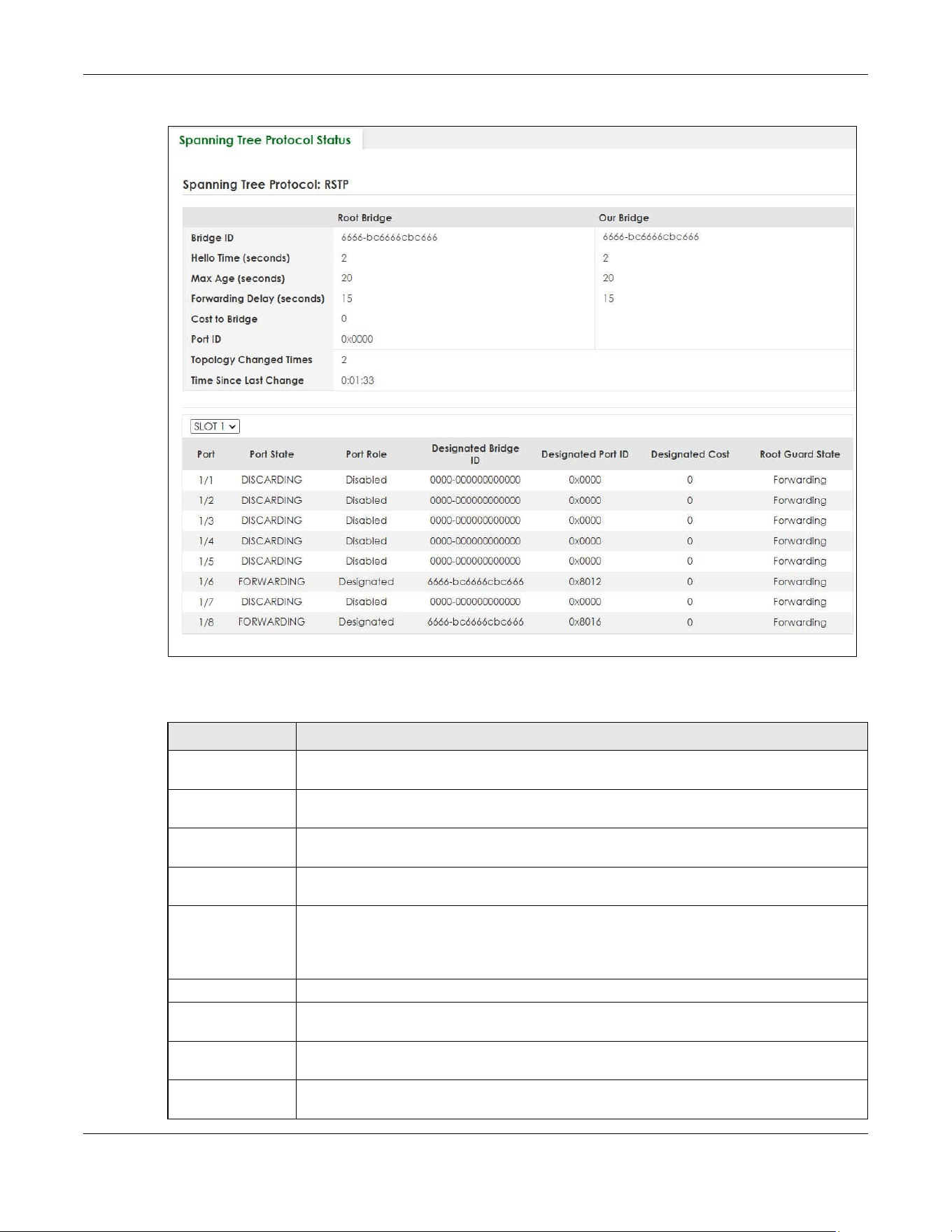
Chapter 54 Spanning Tree Protocol
XGS2220 Series User’s Guide
386
Figure 299 SWITCHING > Spanning Tree Protocol > Spanning Tree Protocol Status: RSTP (Stacking Mode)
The following table describes the labels in this screen.
Table 191 SWITCHING > Spanning Tree Protocol > Spanning Tree Protocol Status: RSTP
LABEL DESCRIPTION
Bridge Root Bridge refers to the base of the spanning tree (the root bridge). Our Bridge is this Switch.
This Switch may also be the root bridge.
Bridge ID This is the unique identifier for this bridge, consisting of bridge priority plus MAC address. This ID
is the same for Root Bridge and Our Bridge if the Switch is the root switch.
Hello Time
(seconds)
This is the time interval (in seconds) at which the root switch transmits a configuration
message. The root bridge determines Hello Time, Max Age and Forwarding Delay.
Max Age
(seconds)
This is the maximum time (in seconds) the Switch can wait without receiving a configuration
message before attempting to reconfigure.
Forwarding Delay
(seconds)
This is the time (in seconds) the root switch will wait before changing states (that is, listening to
learning to forwarding).
Note: The listening state does NOT exist in RSTP.
Cost to Bridge This is the path cost from the root port on this Switch to the root switch.
Port ID This is the priority and number of the port on the Switch through which this Switch must
communicate with the root of the Spanning Tree.
Topology
Changed Times
This is the number of times the spanning tree has been reconfigured.
Time Since Last
Change
This is the time since the spanning tree was last reconfigured.

Chapter 54 Spanning Tree Protocol
XGS2220 Series User’s Guide
387
54.5 Configure Rapid Spanning Tree Protocol
Use this screen to configure RSTP settings, see Section 54.1 on page 378 for more information on RSTP.
Click SWITCHING > Spanning Tree Protocol > RSTP in the navigation panel to display the screen as shown.
SLOT This field appears only in Stacking mode. Click the drop-down list to choose the slot number
of the Switch in a stack.
Port This field displays the number of the port on the Switch. In Stacking mode, the first number
represents the slot ID and the second is the port number.
Port State This field displays the port state in STP.
• DISCARDING – The port does not forward or process received frames or learn MAC
addresses, but still listens for BPDUs.
• LEARNING – The port learns MAC addresses and processes BPDUs, but does NOT forward
frames yet.
• FORWARDING – The port is operating normally. It learns MAC addresses, processes BPDUs
and forwards received frames.
Port Role This field displays the role of the port in STP.
• Root – A forwarding port on a non-root bridge, which has the lowest path cost and is the
best port from the non-root bridge to the root bridge. A root bridge does NOT have a root
port.
• Designated – A forwarding port on the designated bridge for each connected LAN
segment. A designated bridge has the lowest path cost to the root bridge among the
bridges connected to the LAN segment. All the ports on a root bridge (root switch) are
designated ports.
• Alternate – A blocked port, which has a best alternate path to the root bridge. This path is
different from using the root port. The port moves to the forwarding state when the
designated port for the LAN segment fails.
• Backup – A blocked port, which has a backup or redundant path to a LAN segment
where a designated port is already connected when a switch has two links to the same
LAN segment.
• Disabled – Not strictly part of STP. The port can be disabled manually.
Designated Bridge
ID
This field displays the identifier of the designated bridge to which this port belongs when the
port is a designated port. Otherwise, it displays the identifier of the designated bridge for the
LAN segment to which this port is connected.
Designated Port ID This field displays the priority and number of the bridge port (on the designated bridge),
through which the designated bridge transmits the stored configuration messages.
Designated Cost This field displays the path cost to the LAN segment to which the port is connected when the
port is a designated port. Otherwise, it displays the path cost to the root bridge from the
designated port for the LAN segment to which this port is connected.
Root Guard State This field displays the state of the port on which root guard is enabled.
• Root-inconsistent – the Switch receives superior BPDUs on the port and blocks the port.
• Forwarding – the Switch unblocks and allows the port to forward frames again.
Table 191 SWITCHING > Spanning Tree Protocol > Spanning Tree Protocol Status: RSTP (continued)
LABEL DESCRIPTION
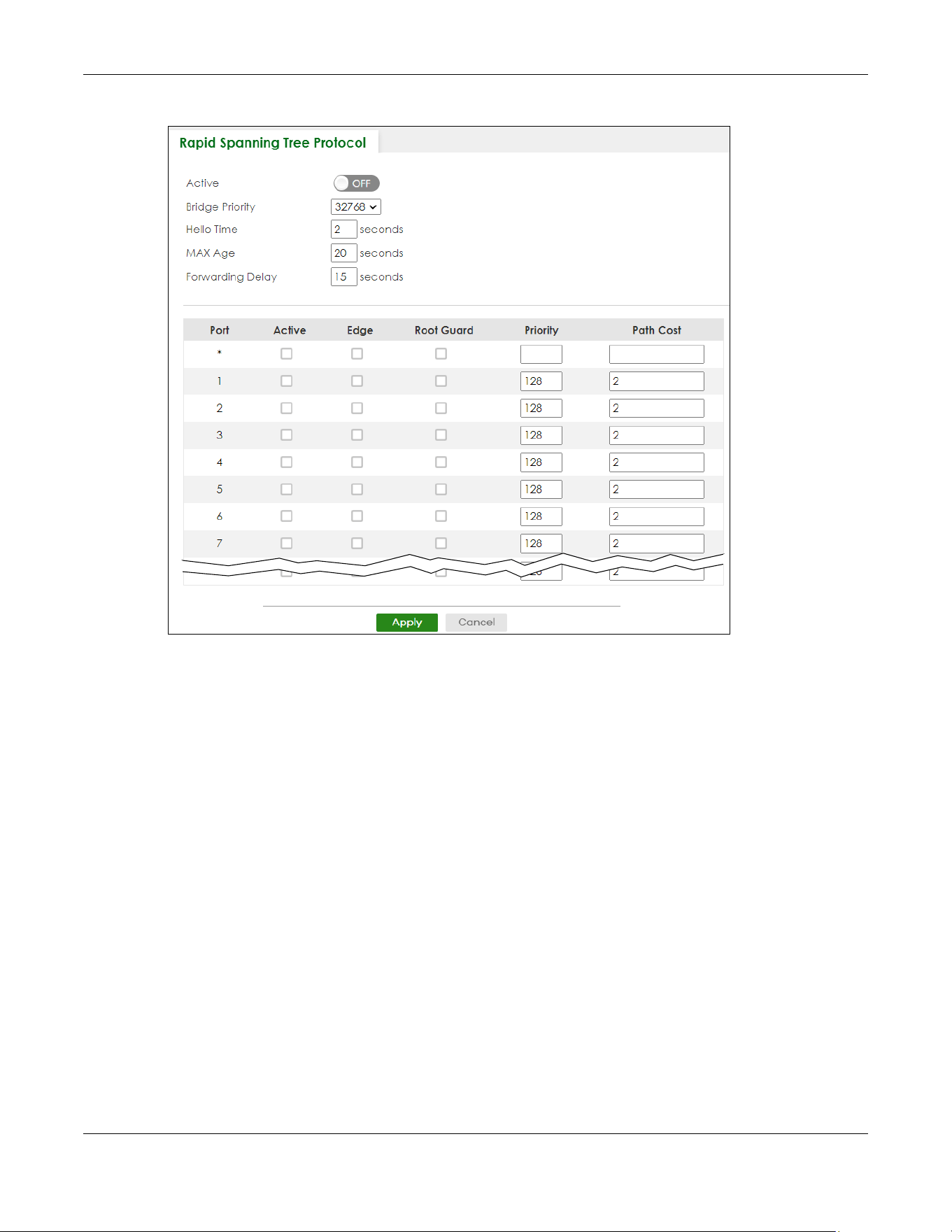
Chapter 54 Spanning Tree Protocol
XGS2220 Series User’s Guide
388
Figure 300 SWITCHING > Spanning Tree Protocol > RSTP (Standalone Mode)

Chapter 54 Spanning Tree Protocol
XGS2220 Series User’s Guide
389
Figure 301 SWITCHING > Spanning Tree Protocol > RSTP (Stacking Mode)
The following table describes the labels in this screen.
Table 192 SWITCHING > Spanning Tree Protocol > RSTP
LABEL DESCRIPTION
Active Enable the switch button to activate RSTP. Disable the switch to disable RSTP.
Note: You must also activate Rapid Spanning Tree (RSTP) in the SWITCHING >
Spanning Tree Protocol > Spanning Tree Setup screen to enable RSTP on the
Switch.
Bridge Priority Bridge priority is used in determining the root switch, root port and designated port. The Switch
with the highest priority (lowest numeric value) becomes the STP root switch. If all Switches
have the same priority, the Switch with the lowest MAC address will then become the root
switch. Select a value from the drop-down list box.
The lower the numeric value you assign, the higher the priority for this bridge.
Bridge Priority determines the root bridge, which in turn determines Hello Time, Max Age and
Forwarding Delay.
Hello Time This is the time interval in seconds between BPDU (Bridge Protocol Data Units) configuration
message generations by the root switch. The allowed range is 1 to 10 seconds.

Chapter 54 Spanning Tree Protocol
XGS2220 Series User’s Guide
390
Max Age This is the maximum time (in seconds) the Switch can wait without receiving a BPDU before
attempting to reconfigure. All Switch ports (except for designated ports) should receive BPDUs
at regular intervals. Any port that ages out STP information (provided in the last BPDU)
becomes the designated port for the attached LAN. If it is a root port, a new root port is
selected from among the Switch ports attached to the network. The allowed range is 6 to 40
seconds.
Forwarding Delay This is the maximum time (in seconds) the Switch will wait before changing states. This delay is
required because every Switch must receive information about topology changes before it
starts to forward frames. In addition, each port needs time to listen for conflicting information
that would make it return to a blocking state; otherwise, temporary data loops might result.
The allowed range is 4 to 30 seconds.
As a general rule:
2 * (Forward Delay – 1) >= Max Age >= 2 * (Hello Time + 1)
SLOT This field appears only in Stacking mode. Click the drop-down list to choose the slot number of
the Switch in a stack.
Port This field displays the port number. In Stacking mode, the first number represents the slot ID and
the second is the port number. Please note that the default stacking ports (the last four ports
of your Switch) cannot be configured. They are reserved for stacking only.
* Settings in this row apply to all ports.
Use this row only if you want to make some settings the same for all ports. Use this row first to set
the common settings and then make adjustments on a port-by-port basis.
Note: Changes in this row are copied to all the ports as soon as you make them.
Active Select this check box to activate RSTP on this port.
Edge Select this check box to configure a port as an edge port when it is directly attached to a
computer. An edge port changes its initial STP port state from blocking state to forwarding
state immediately without going through listening and learning states right after the port is
configured as an edge port or when its link status changes.
Note: An edge port becomes a non-edge port as soon as it receives a Bridge
Protocol Data Unit (BPDU).
Root Guard Select this check box to enable root guard on this port in order to prevent the switches
attached to the port from becoming the root bridge.
With root guard enabled, a port is blocked when the Switch receives a superior BPDU on it. The
Switch allows traffic to pass through this port again when the switch connected to the port
stops to send superior BPDUs.
Priority Configure the priority for each port here.
Priority decides which port should be disabled when more than one port forms a loop in a
switch. Ports with a higher priority numeric value are disabled first. The allowed range is
between 0 and 255 and the default value is 128.
Path Cost Path cost is the cost of transmitting a frame on to a LAN through that port. It is recommended
to assign this value according to the speed of the bridge. The slower the media, the higher the
cost.
Note: Set the value to 0 to use the auto path cost you set in the SWITCHING >
Spanning Tree Protocol > Spanning Tree Setup screen (see Auto Path-cost
Mode).
Apply Click Apply to save your changes to the Switch’s run-time memory. The Switch loses these
changes if it is turned off or loses power, so use the Save link on the top navigation panel to
save your changes to the non-volatile memory when you are done configuring.
Cancel Click Cancel to begin configuring this screen afresh.
Table 192 SWITCHING > Spanning Tree Protocol > RSTP (continued)
LABEL DESCRIPTION

Chapter 54 Spanning Tree Protocol
XGS2220 Series User’s Guide
391
54.6 Multiple Rapid Spanning Tree Protocol
Click SWITCHING > Spanning Tree Protocol > Spanning Tree Protocol Status in the navigation panel to
display the status screen as shown next. See Section 54.6 on page 391 for more information on MRSTP.
Note: This screen is only available after you activate MRSTP on the Switch.
Figure 302 SWITCHING > Spanning Tree Protocol > Spanning Tree Protocol Status: MRSTP (Standalone
Mode)
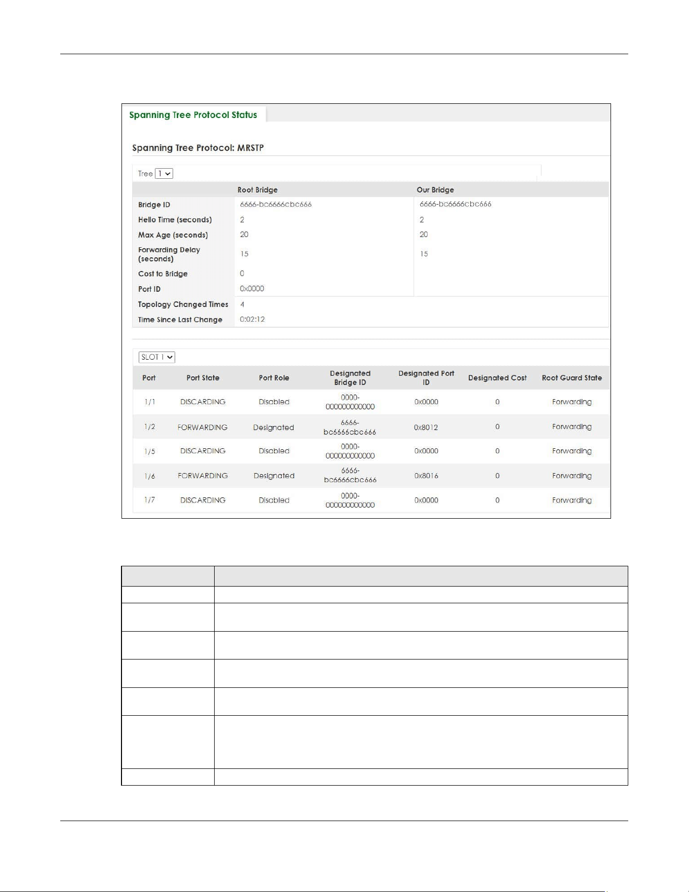
Chapter 54 Spanning Tree Protocol
XGS2220 Series User’s Guide
392
Figure 303 SWITCHING > Spanning Tree Protocol > Spanning Tree Protocol Status: MRSTP (Stacking
Mode)
The following table describes the labels in this screen.
Table 193 SWITCHING > Spanning Tree Protocol > Spanning Tree Protocol Status: MRSTP
LABEL DESCRIPTION
Tree Select which STP tree configuration you want to view.
Bridge Root Bridge refers to the base of the spanning tree (the root bridge). Our Bridge is this switch.
This Switch may also be the root bridge.
Bridge ID This is the unique identifier for this bridge, consisting of bridge priority plus MAC address. This ID
is the same for Root Bridge and Our Bridge if the Switch is the root switch.
Hello Time
(seconds)
This is the time interval (in seconds) at which the root switch transmits a configuration
message. The root bridge determines Hello Time, Max Age and Forwarding Delay.
Max Age
(seconds)
This is the maximum time (in seconds) the Switch can wait without receiving a configuration
message before attempting to reconfigure.
Forwarding Delay
(seconds)
This is the time (in seconds) the root switch will wait before changing states (that is, listening to
learning to forwarding).
Note: The listening state does not exist in RSTP.
Cost to Bridge This is the path cost from the root port on this Switch to the root switch.

Chapter 54 Spanning Tree Protocol
XGS2220 Series User’s Guide
393
54.7 Configure Multiple Rapid Spanning Tree Protocol
To configure MRSTP, click SWITCHING > Spanning Tree Protocol > MRSTP in the navigation panel to
display the screen as shown.
Port ID This is the priority and number of the port on the Switch through which this Switch must
communicate with the root of the Spanning Tree.
Topology
Changed Times
This is the number of times the spanning tree has been reconfigured.
Time Since Last
Change
This is the time since the spanning tree was last reconfigured.
SLOT This field appears only in Stacking mode. Click the drop-down list to choose the slot number
of the Switch in a stack.
Port This field displays the number of the port on the Switch. In Stacking mode, the first number
represents the slot ID and the second is the port number.
Port State This field displays the port state in STP.
• DISCARDING – The port does not forward or process received frames or learn MAC
addresses, but still listens for BPDUs.
• LEARNING – The port learns MAC addresses and processes BPDUs, but does not forward
frames yet.
• FORWARDING – The port is operating normally. It learns MAC addresses, processes BPDUs
and forwards received frames.
Port Role This field displays the role of the port in STP.
• Root – A forwarding port on a non-root bridge, which has the lowest path cost and is the
best port from the non-root bridge to the root bridge. A root bridge does not have a root
port.
• Designated – A forwarding port on the designated bridge for each connected LAN
segment. A designated bridge has the lowest path cost to the root bridge among the
bridges connected to the LAN segment. All the ports on a root bridge (root switch) are
designated ports.
• Alternate – A blocked port, which has a best alternate path to the root bridge. This path is
different from using the root port. The port moves to the forwarding state when the
designated port for the LAN segment fails.
• Backup – A blocked port, which has a backup or redundant path to a LAN segment
where a designated port is already connected when a switch has two links to the same
LAN segment.
• Disabled – Not strictly part of STP. The port can be disabled manually.
Designated Bridge
ID
This field displays the identifier of the designated bridge to which this port belongs when the
port is a designated port. Otherwise, it displays the identifier of the designated bridge for the
LAN segment to which this port is connected.
Designated Port ID This field displays the priority and number of the bridge port (on the designated bridge),
through which the designated bridge transmits the stored configuration messages.
Designated Cost This field displays the path cost to the LAN segment to which the port is connected when the
port is a designated port. Otherwise, it displays the path cost to the root bridge from the
designated port for the LAN segment to which this port is connected.
Root Guard State This field displays the state of the port on which root guard is enabled.
• Root – inconsistent – the Switch receives superior BPDUs on the port and blocks the port.
• Forwarding – the Switch unblocks and allows the port to forward frames again.
Table 193 SWITCHING > Spanning Tree Protocol > Spanning Tree Protocol Status: MRSTP (continued)
LABEL DESCRIPTION
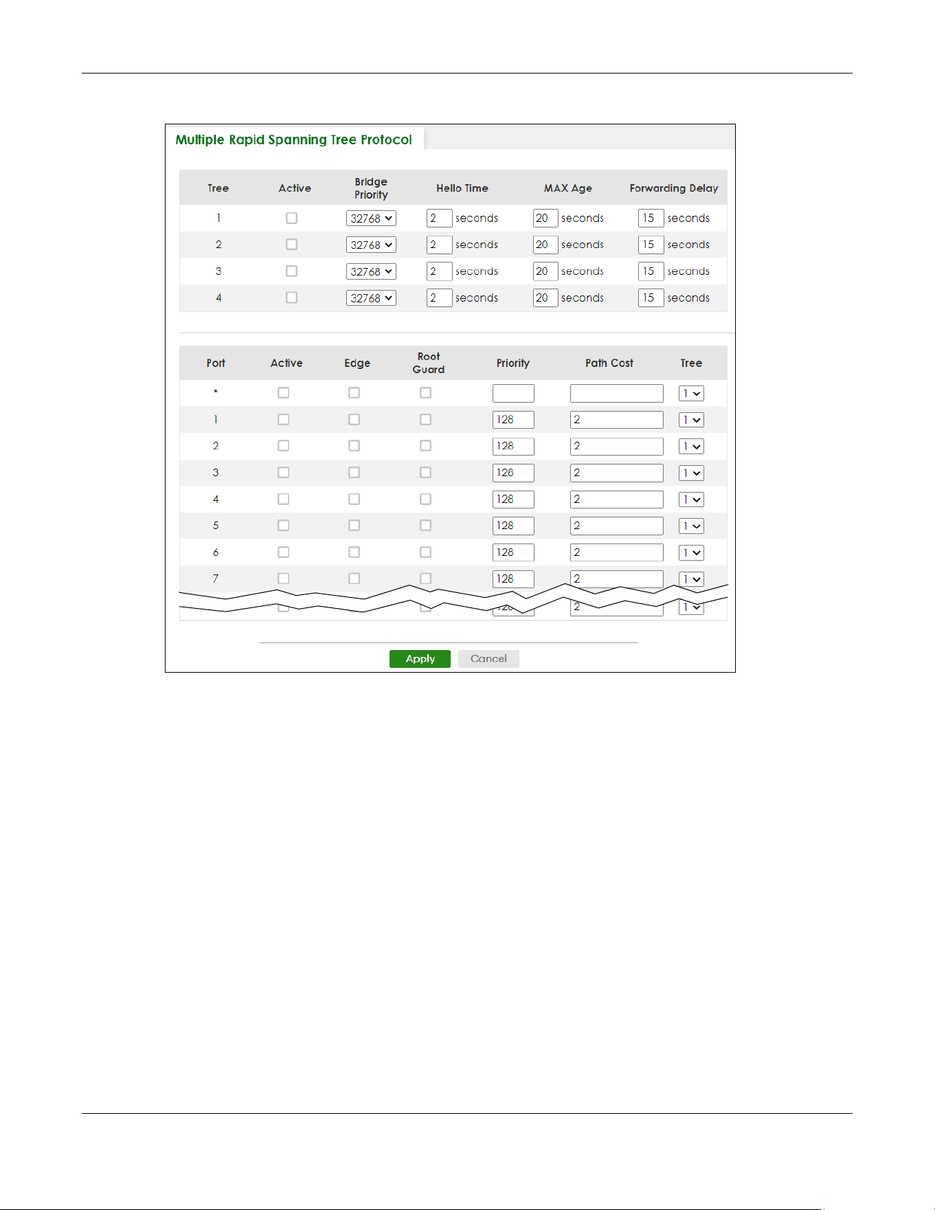
Chapter 54 Spanning Tree Protocol
XGS2220 Series User’s Guide
394
Figure 304 SWITCHING > Spanning Tree Protocol > MRSTP (Standalone Mode)

Chapter 54 Spanning Tree Protocol
XGS2220 Series User’s Guide
395
Figure 305 SWITCHING > Spanning Tree Protocol > MRSTP (Stacking Mode)
The following table describes the labels in this screen.
Table 194 SWITCHING > Spanning Tree Protocol > MRSTP
LABEL DESCRIPTION
Tree This is the index number of the STP trees.
Active Select this check box to activate an STP tree. Clear this check box to disable an STP tree.
Note: You must also activate Multiple Rapid Spanning Tree (MRSTP) in the
SWITHCING > Spanning Tree Protocol > Spanning Tree Setup screen to enable
MRSTP on the Switch.
Bridge Priority Bridge priority is used in determining the root switch, root port and designated port. The switch
with the highest priority (lowest numeric value) becomes the STP root switch. If all switches
have the same priority, the switch with the lowest MAC address will then become the root
switch. Select a value from the drop-down list box.
The lower the numeric value you assign, the higher the priority for this bridge.
Bridge Priority determines the root bridge, which in turn determines Hello Time, Max Age and
Forwarding Delay.
Hello Time This is the time interval in seconds between BPDU (Bridge Protocol Data Units) configuration
message generations by the root switch. The allowed range is 1 to 10 seconds.

Chapter 54 Spanning Tree Protocol
XGS2220 Series User’s Guide
396
Max Age This is the maximum time (in seconds) the Switch can wait without receiving a BPDU before
attempting to reconfigure. All Switch ports (except for designated ports) should receive BPDUs
at regular intervals. Any port that ages out STP information (provided in the last BPDU)
becomes the designated port for the attached LAN. If it is a root port, a new root port is
selected from among the Switch ports attached to the network. The allowed range is 6 to 40
seconds.
Forwarding Delay This is the maximum time (in seconds) the Switch will wait before changing states. This delay is
required because every switch must receive information about topology changes before it
starts to forward frames. In addition, each port needs time to listen for conflicting information
that would make it return to a blocking state; otherwise, temporary data loops might result.
The allowed range is 4 to 30 seconds.
As a general rule:
2 * (Forward Delay – 1) >= Max Age >= 2 * (Hello Time + 1)
SLOT This field appears only in Stacking mode. Click the drop-down list to choose the slot number of
the Switch in a stack.
Port This field displays the port number. In Stacking mode, the first number represents the slot ID and
the second is the port number. Please note that the default stacking ports (the last four ports
of your Switch) cannot be configured. They are reserved for stacking only.
* Settings in this row apply to all ports.
Use this row only if you want to make some settings the same for all ports. Use this row first to set
the common settings and then make adjustments on a port-by-port basis.
Note: Changes in this row are copied to all the ports as soon as you make them.
Active Select this check box to activate STP on this port.
Edge Select this check box to configure a port as an edge port when it is directly attached to a
computer. An edge port changes its initial STP port state from blocking state to forwarding
state immediately without going through listening and learning states right after the port is
configured as an edge port or when its link status changes.
Note: An edge port becomes a non-edge port as soon as it receives a Bridge
Protocol Data Unit (BPDU).
Root Guard Select this check box to enable root guard on this port in order to prevent the switch(es)
attached to the port from becoming the root bridge.
With root guard enabled, a port is blocked when the Switch receives a superior BPDU on it. The
Switch allows traffic to pass through this port again when the switch connected to the port
stops to send superior BPDUs.
Priority Configure the priority for each port here.
Priority decides which port should be disabled when more than one port forms a loop in a
switch. Ports with a higher priority numeric value are disabled first. The allowed range is
between 0 and 255 and the default value is 128.
Path Cost Path cost is the cost of transmitting a frame on to a LAN through that port. It is recommended
to assign this value according to the speed of the bridge. The slower the media, the higher the
cost.
Note: Set the value to 0 to use the auto path cost you set in the SWITCHING >
Spanning Tree Protocol > Spanning Tree Setup screen (see Auto Path-cost
Mode).
Tree Select which STP tree configuration this port should participate in.
Table 194 SWITCHING > Spanning Tree Protocol > MRSTP (continued)
LABEL DESCRIPTION

Chapter 54 Spanning Tree Protocol
XGS2220 Series User’s Guide
397
54.8 Multiple Spanning Tree Protocol Status
Click SWITCHING > Spanning Tree Protocol > Spanning Tree Protocol Status in the navigation panel to
display the status screen as shown next.
Note: This screen is only available after you activate MSTP on the Switch.
Apply Click Apply to save your changes to the Switch’s run-time memory. The Switch loses these
changes if it is turned off or loses power, so use the Save link on the top navigation panel to
save your changes to the non-volatile memory when you are done configuring.
Cancel Click Cancel to begin configuring this screen afresh.
Table 194 SWITCHING > Spanning Tree Protocol > MRSTP (continued)
LABEL DESCRIPTION

Chapter 54 Spanning Tree Protocol
XGS2220 Series User’s Guide
398
Figure 306 SWITCHING > Spanning Tree Protocol > Spanning Tree Protocol Status: MSTP (Standalone
Mode)
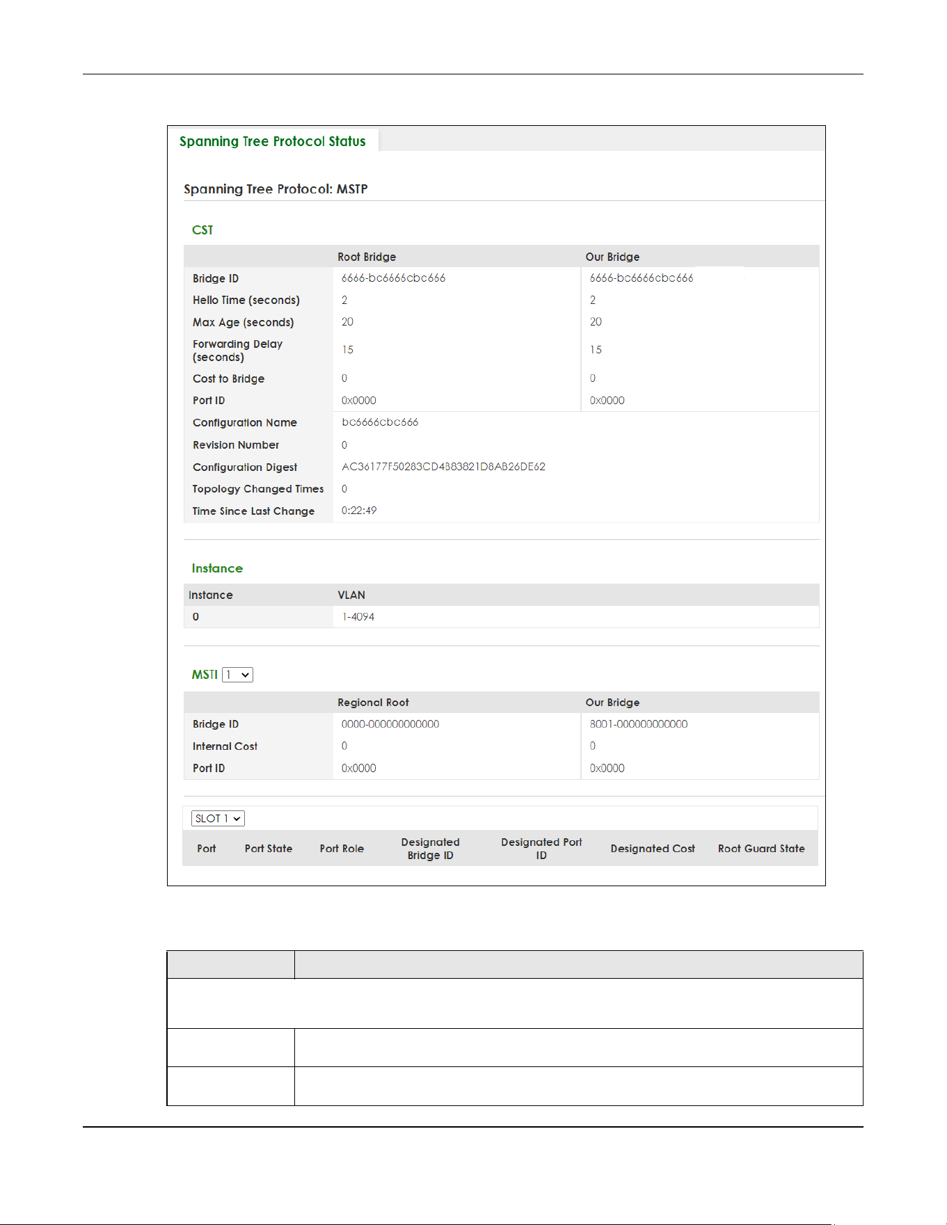
Chapter 54 Spanning Tree Protocol
XGS2220 Series User’s Guide
399
Figure 307 SWITCHING > Spanning Tree Protocol > Spanning Tree Protocol Status: MSTP (Stacking Mode)
The following table describes the labels in this screen.
Table 195 SWITCHING > Spanning Tree Protocol > Spanning Tree Protocol Status: MSTP
LABEL DESCRIPTION
CST
This section describes the Common Spanning Tree settings.
Bridge Root Bridge refers to the base of the spanning tree (the root bridge). Our Bridge is this switch.
This Switch may also be the root bridge.
Bridge ID This is the unique identifier for this bridge, consisting of bridge priority plus MAC address. This ID
is the same for Root Bridge and Our Bridge if the Switch is the root switch.

Chapter 54 Spanning Tree Protocol
XGS2220 Series User’s Guide
400
Hello Time
(seconds)
This is the time interval (in seconds) at which the root switch transmits a configuration
message. The root bridge determines Hello Time, Max Age and Forwarding Delay.
Max Age
(seconds)
This is the maximum time (in seconds) the Switch can wait without receiving a configuration
message before attempting to reconfigure.
Forwarding Delay
(seconds)
This is the time (in seconds) the root switch will wait before changing states (that is, listening to
learning to forwarding).
Cost to Bridge This is the path cost from the root port on this Switch to the root switch.
Port ID This is the priority and number of the port on the Switch through which this Switch must
communicate with the root of the Spanning Tree.
Configuration
Name
This field displays the configuration name for this MST region.
Revision Number This field displays the revision number for this MST region.
Configuration
Digest
A configuration digest is generated from the VLAN-MSTI mapping information.
This field displays the 16-octet signature that is included in an MSTP BPDU. This field displays the
digest when MSTP is activated on the system.
Topology
Changed Times
This is the number of times the spanning tree has been reconfigured.
Time Since Last
Change
This is the time since the spanning tree was last reconfigured.
Instance These fields display the MSTI to VLAN mapping. In other words, which VLANs run on each
spanning tree instance.
Instance This field displays the MSTI ID.
VLAN This field displays which VLANs are mapped to an MSTI.
MSTI
MSTI Select the MST instance settings you want to view.
Regional Root refers to the base of the MST instance. Our Bridge is this switch. This Switch may
also be the root bridge.
Bridge ID This is the unique identifier for this bridge, consisting of bridge priority plus MAC address. This ID
is the same for Regional Root and Our Bridge if the Switch is the root switch.
Internal Cost This is the path cost from the root port in this MST instance to the regional root switch.
Port ID This is the priority and number of the port on the Switch through which this Switch must
communicate with the root of the MST instance.
SLOT This field appears only in Stacking mode. Click the drop-down list to choose the slot number
of the Switch in a stack.
Port This field displays the number of the port on the Switch. In Stacking mode, the first number
represents the slot ID and the second is the port number.
Port State This field displays the port state in STP.
• DISCARDING – The port does not forward or process received frames or learn MAC
addresses, but still listens for BPDUs.
• LEARNING – The port learns MAC addresses and processes BPDUs, but does not forward
frames yet.
• FORWARDING – The port is operating normally. It learns MAC addresses, processes BPDUs
and forwards received frames.
Table 195 SWITCHING > Spanning Tree Protocol > Spanning Tree Protocol Status: MSTP (continued)
LABEL DESCRIPTION
Chapter 54 Spanning Tree Protocol
XGS2220 Series User’s Guide
401
54.9 Configure Multiple Spanning Tree Protocol
To configure MSTP, click SWITCHING > Spanning Tree Protocol > MSTP in the navigation panel to display
the screen as shown.
Port Role This field displays the role of the port in STP.
• Root – A forwarding port on a non-root bridge, which has the lowest path cost and is the
best port from the non-root bridge to the root bridge. A root bridge does not have a root
port.
• Designated – A forwarding port on the designated bridge for each connected LAN
segment. A designated bridge has the lowest path cost to the root bridge among the
bridges connected to the LAN segment. All the ports on a root bridge (root switch) are
designated ports.
• Alternate – A blocked port, which has a best alternate path to the root bridge. This path is
different from using the root port. The port moves to the forwarding state when the
designated port for the LAN segment fails.
• Backup – A blocked port, which has a backup or redundant path to a LAN segment
where a designated port is already connected when a switch has two links to the same
LAN segment.
• Disabled – Not strictly part of STP. The port can be disabled manually.
Designated Bridge
ID
This field displays the identifier of the designated bridge to which this port belongs when the
port is a designated port. Otherwise, it displays the identifier of the designated bridge for the
LAN segment to which this port is connected.
Designated Port ID This field displays the priority and number of the bridge port (on the designated bridge),
through which the designated bridge transmits the stored configuration messages.
Designated Cost This field displays the path cost to the LAN segment to which the port is connected when the
port is a designated port. Otherwise, it displays the path cost to the root bridge from the
designated port for the LAN segment to which this port is connected.
Root Guard State This field displays the state of the port on which root guard is enabled.
• Root-inconsistent – the Switch receives superior BPDUs on the port and blocks the port.
• Forwarding – the Switch unblocks and allows the port to forward frames again.
Table 195 SWITCHING > Spanning Tree Protocol > Spanning Tree Protocol Status: MSTP (continued)
LABEL DESCRIPTION
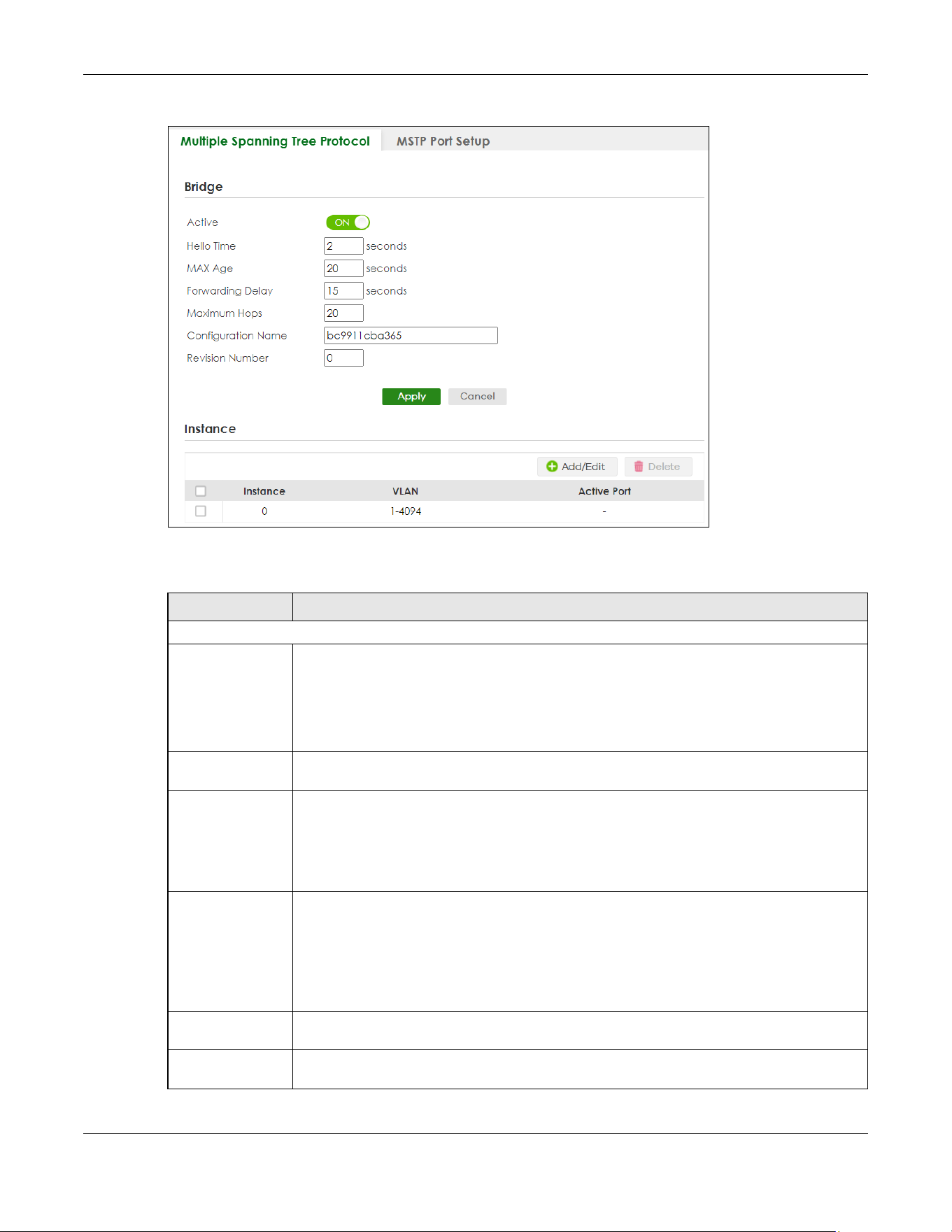
Chapter 54 Spanning Tree Protocol
XGS2220 Series User’s Guide
402
Figure 308 SWITCHING > Spanning Tree Protocol > MSTP > Multiple Spanning Tree Protocol
The following table describes the labels in this screen.
Table 196 SWITCHING > Spanning Tree Protocol > MSTP > Multiple Spanning Tree Protocol
LABEL DESCRIPTION
Bridge
Active Enable the switch button to activate MSTP on the Switch. Disable the switch to disable MSTP
on the Switch.
Note: You must also activate Multiple Spanning Tree (MSTP) in the SWITCHING >
Spanning Tree Protocol > Spanning Tree Setup screen to enable MSTP on the
Switch.
Hello Time This is the time interval in seconds between BPDU (Bridge Protocol Data Units) configuration
message generations by the root switch. The allowed range is 1 to 10 seconds.
Max Age This is the maximum time (in seconds) a switch can wait without receiving a BPDU before
attempting to reconfigure. All switch ports (except for designated ports) should receive BPDUs
at regular intervals. Any port that ages out STP information (provided in the last BPDU)
becomes the designated port for the attached LAN. If it is a root port, a new root port is
selected from among the Switch ports attached to the network. The allowed range is 6 to 40
seconds.
Forwarding Delay This is the maximum time (in seconds) a switch will wait before changing states. This delay is
required because every switch must receive information about topology changes before it
starts to forward frames. In addition, each port needs time to listen for conflicting information
that would make it return to a blocking state; otherwise, temporary data loops might result.
The allowed range is 4 to 30 seconds. As a general rule:
Note: 2 * (Forward Delay – 1) >= Max Age >= 2 * (Hello Time + 1)
Maximum hops Enter the number of hops (between 1 and 255) in an MSTP region before the BPDU is
discarded and the port information is aged.
Configuration
Name
Enter a descriptive name (up to 32 printable ASCII characters except [ ? ], [ | ], [ ' ], [ " ], or [ ,
]) of an MST region.
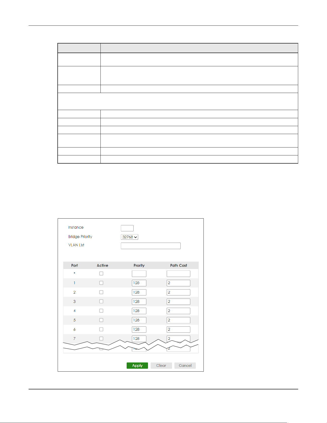
Chapter 54 Spanning Tree Protocol
XGS2220 Series User’s Guide
403
54.9.1 Add/Edit Multiple Spanning Tree
Click Add/Edit, or select an entry and click Add/Edit in the SWITCHING > Spanning Tree Protocol > MSTP >
Multiple Spanning Tree Protocol screen to display this screen.
Figure 309 SWITCHING > Spanning Tree Protocol > MSTP > Multiple Spanning Tree Protocol > Add/Edit
(Standalone Mode)
Revision Number Enter a number to identify a region’s configuration. Devices must have the same revision
number to belong to the same region.
Apply Click Apply to save your changes to the Switch’s run-time memory. The Switch loses these
changes if it is turned off or loses power, so use the Save link on the top navigation panel to
save your changes to the non-volatile memory when you are done configuring.
Cancel Click Cancel to begin configuring this screen afresh.
Instance
Use this section to configure MSTI (Multiple Spanning Tree Instance) settings.
Instance This field displays the ID of an MST instance.
VLAN This field displays the VID (or VID ranges) to which the MST instance is mapped.
Active Port This field display the ports configured to participate in the MST instance.
Select an entry’s check box to select a specific entry. Otherwise, select the check box in the
table heading row to select all entries.
Add/Edit Click Add/Edit to add a new instance or edit a selected one.
Delete Click Delete to remove the selected instances.
Table 196 SWITCHING > Spanning Tree Protocol > MSTP > Multiple Spanning Tree Protocol (continued)
LABEL DESCRIPTION
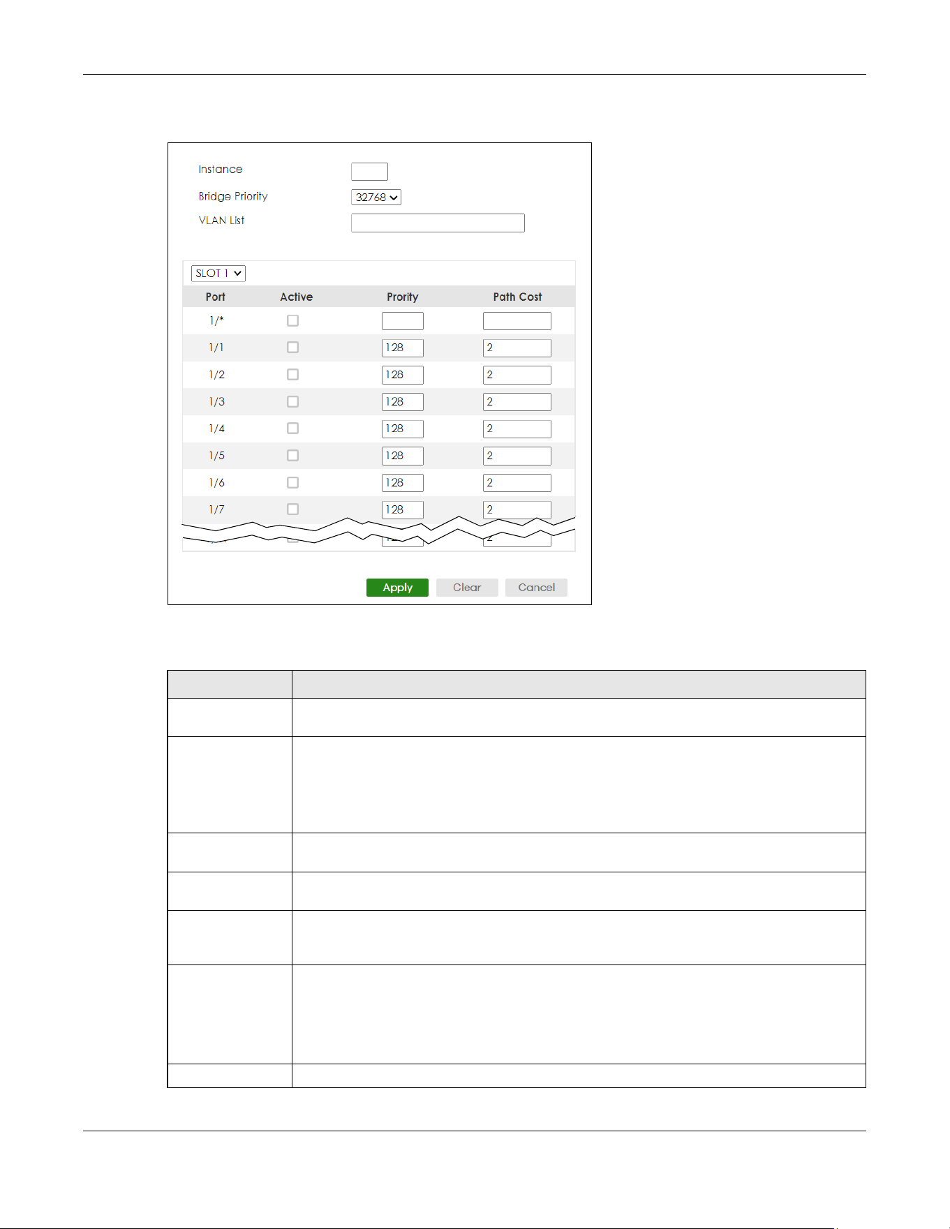
Chapter 54 Spanning Tree Protocol
XGS2220 Series User’s Guide
404
Figure 310 SWITCHING > Spanning Tree Protocol > MSTP > Multiple Spanning Tree Protocol > Add/Edit
(Stacking Mode)
The following table describes the labels in this screen.
Table 197 SWITCHING > Spanning Tree Protocol > MSTP > Multiple Spanning Tree Protocol > Add/Edit
LABEL DESCRIPTION
Instance Enter the number you want to use to identify this MST instance on the Switch. The Switch
supports instance numbers 0 – 16.
Bridge Priority Set the priority of the Switch for the specific spanning tree instance. The lower the number, the
more likely the Switch will be chosen as the root bridge within the spanning tree instance.
Enter priority values between 0 and 61440 in increments of 4096 (thus valid values are 4096,
8192, 12288, 16384, 20480, 24576, 28672, 32768, 36864, 40960, 45056, 49152, 53248, 57344 and
61440).
VLAN List Enter the VLAN ID range. You can specify multiple VLAN ID range separated by (no space)
comma (,) or hyphen (“-”) for a range. For example, enter “1,3,5-7” for VLANs 1, 3, 5, 6, and 7.
SLOT This field appears only in Stacking mode. Click the drop-down list to choose the slot number of
the Switch in a stack.
Port This field displays the port number. In Stacking mode, the first number represents the slot ID
and the second is the port number. Please note that the default stacking ports (the last four
ports of your Switch) cannot be configured. They are reserved for stacking only.
* Settings in this row apply to all ports.
Use this row only if you want to make some settings the same for all ports. Use this row first to set
the common settings and then make adjustments on a port-by-port basis.
Note: Changes in this row are copied to all the ports as soon as you make them.
Active Select this check box to add this port to the MST instance.
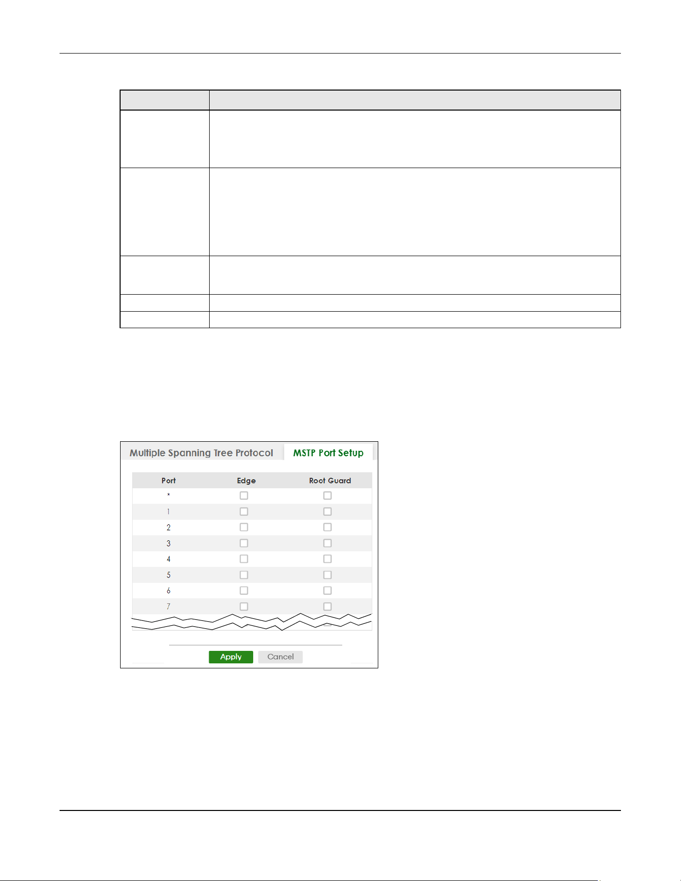
Chapter 54 Spanning Tree Protocol
XGS2220 Series User’s Guide
405
54.10 Multiple Spanning Tree Protocol Port Setup
Click SWITCHING > Spanning Tree Protocol > MSTP > MSTP Port Setup to display the screen as shown next.
Figure 311 SWITCHING > Spanning Tree Protocol > MSTP > MSTP Port Setup (Standalone Mode)
Priority Configure the priority for each port here.
Priority decides which port should be disabled when more than one port forms a loop in the
Switch. Ports with a higher priority numeric value are disabled first. The allowed range is
between 0 and 255 and the default value is 128.
Path Cost Path cost is the cost of transmitting a frame on to a LAN through that port. It is recommended
to assign this value according to the speed of the bridge. The slower the media, the higher the
cost.
Note: Set the value to 0 to use the auto path cost you set in the SWITCHING >
Spanning Tree Protocol > Spanning Tree Setup screen (see Auto Path-cost
Mode).
Apply Click Apply to save your changes to the Switch’s run-time memory. The Switch loses these
changes if it is turned off or loses power, so use the Save link on the top navigation panel to
save your changes to the non-volatile memory when you are done configuring.
Clear Click Clear to clear the fields to the factory defaults.
Cancel Click Cancel to not save the configuration you make and return to the last screen.
Table 197 SWITCHING > Spanning Tree Protocol > MSTP > Multiple Spanning Tree Protocol > Add/Edit
LABEL DESCRIPTION

Chapter 54 Spanning Tree Protocol
XGS2220 Series User’s Guide
406
Figure 312 SWITCHING > Spanning Tree Protocol > MSTP > MSTP Port Setup (Stacking Mode)
The following table describes the labels in this screen.
Table 198 SWITCHING > Spanning Tree Protocol > MSTP > MSTP Port Setup
LABEL DESCRIPTION
SLOT This field appears only in Stacking mode. Click the drop-down list to choose the slot number of
the Switch in a stack.
Port This field displays the port number. In Stacking mode, the first number represents the slot ID
and the second is the port number. Please note that the default stacking ports (the last four
ports of your Switch) cannot be configured. They are reserved for stacking only.
* Settings in this row apply to all ports.
Use this row only if you want to make some settings the same for all ports. Use this row first to
set the common settings and then make adjustments on a port-by-port basis.
Note: Changes in this row are copied to all the ports as soon as you make them.
Edge Select this check box to configure a port as an edge port when it is directly attached to a
computer. An edge port changes its initial STP port state from blocking state to forwarding
state immediately without going through listening and learning states right after the port is
configured as an edge port or when its link status changes.
Note: An edge port becomes a non-edge port as soon as it receives a Bridge
Protocol Data Unit (BPDU).
Root Guard Select this check box to enable root guard on this port in order to prevent the switches
attached to the port from becoming the root bridge.
With root guard enabled, a port is blocked when the Switch receives a superior BPDU on it.
The Switch allows traffic to pass through this port again when the switch connected to the
port stops to send superior BPDUs.
Apply Click Apply to save your changes to the Switch’s run-time memory. The Switch loses these
changes if it is turned off or loses power, so use the Save link on the top navigation panel to
save your changes to the non-volatile memory when you are done configuring.
Cancel Click Cancel to begin configuring this screen afresh.
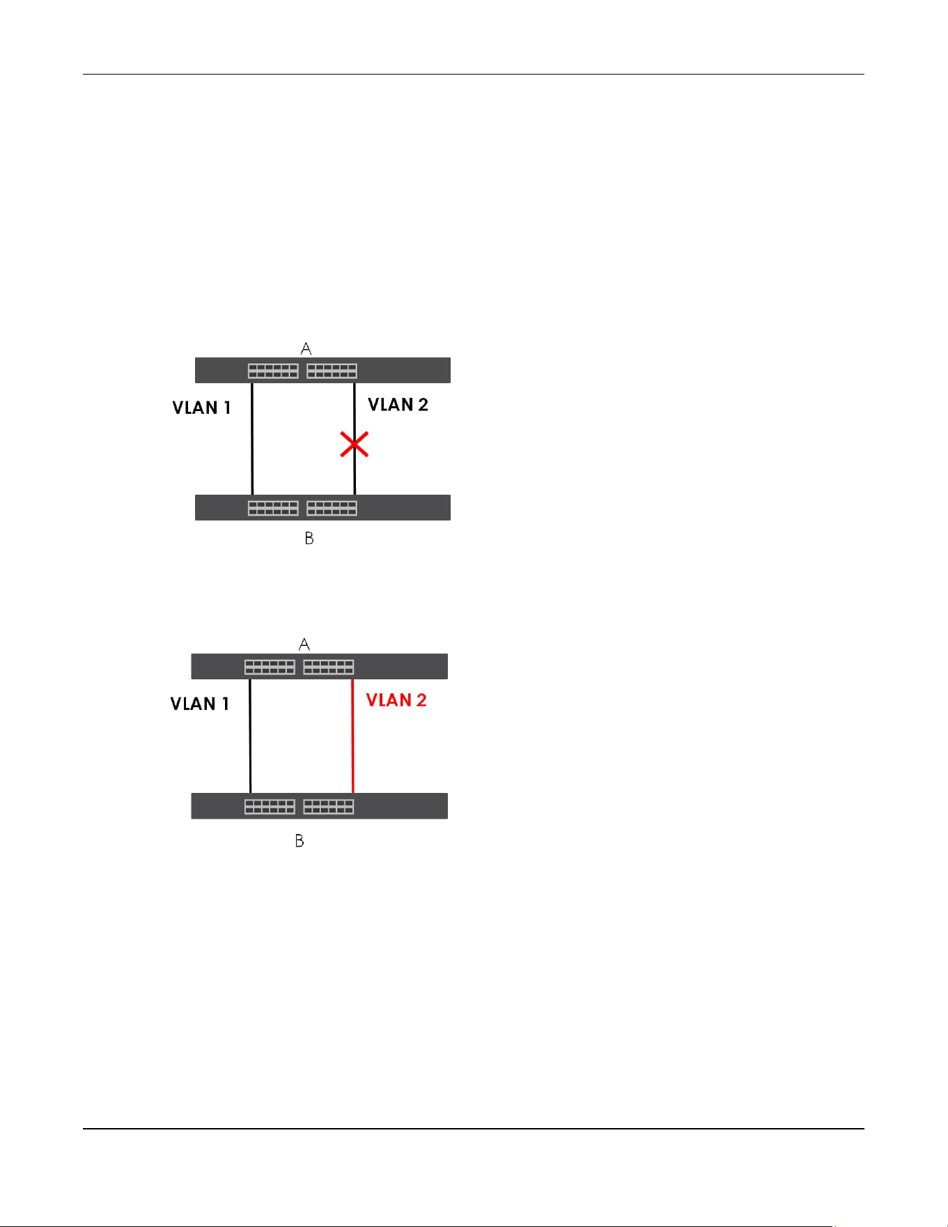
Chapter 54 Spanning Tree Protocol
XGS2220 Series User’s Guide
407
54.11 Technical Reference
This section provides technical background information on the topics discussed in this chapter.
54.11.1 MSTP Network Example
The following figure shows a network example where two VLANs are configured on the two switches. If
the switches are using STP or RSTP, the link for VLAN 2 will be blocked as STP and RSTP allow only one link
in the network and block the redundant link.
Figure 313 STP/RSTP Network Example
With MSTP, VLANs 1 and 2 are mapped to different spanning trees in the network. Therefore traffic from
the two VLANs travel on different paths. The following figure shows the network example using MSTP.
Figure 314 MSTP Network Example
54.11.2 MST Region
An MST region is a logical grouping of multiple network devices that appears as a single device to the
rest of the network. Each MSTP-enabled device can only belong to one MST region. When BPDUs enter
an MST region, external path cost (of paths outside this region) is increased by one. Internal path cost (of
paths within this region) is increased by one when BPDUs traverse the region.
Devices that belong to the same MST region are configured to have the same MSTP configuration
identification settings. These include the following parameters:
• Name of the MST region
• Revision level as the unique number for the MST region

Chapter 54 Spanning Tree Protocol
XGS2220 Series User’s Guide
408
• VLAN-to-MST Instance mapping
54.11.3 MST Instance
An MST Instance (MSTI) is a spanning tree instance. VLANs can be configured to run on a specific MSTI.
Each created MSTI is identified by a unique number (known as an MST ID) known internally to a region.
Therefore an MSTI does not span across MST regions.
The following figure shows an example where there are two MST regions. Regions 1 and 2 have two
spanning tree instances.
Figure 315 MSTIs in Different Regions
54.11.4 Common and Internal Spanning Tree (CIST)
A CIST represents the connectivity of the entire network and it is equivalent to a spanning tree in an STP/
RSTP. The CIST is the default MST instance (MSTID 0). Any VLANs that are not members of an MST instance
are members of the CIST. In an MSTP-enabled network, there is only one CIST that runs between MST
regions and single spanning tree devices. A network may contain multiple MST regions and other
network segments running RSTP.
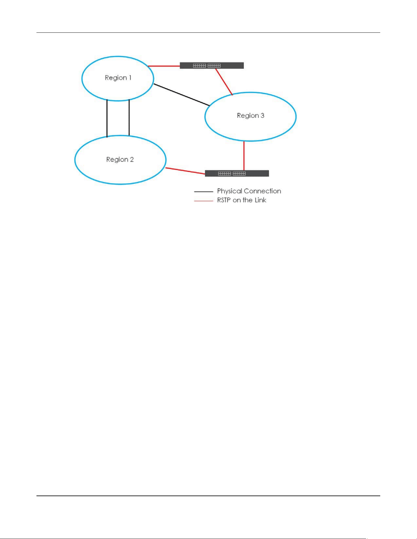
Chapter 54 Spanning Tree Protocol
XGS2220 Series User’s Guide
409
Figure 316 MSTP and Legacy RSTP Network Example
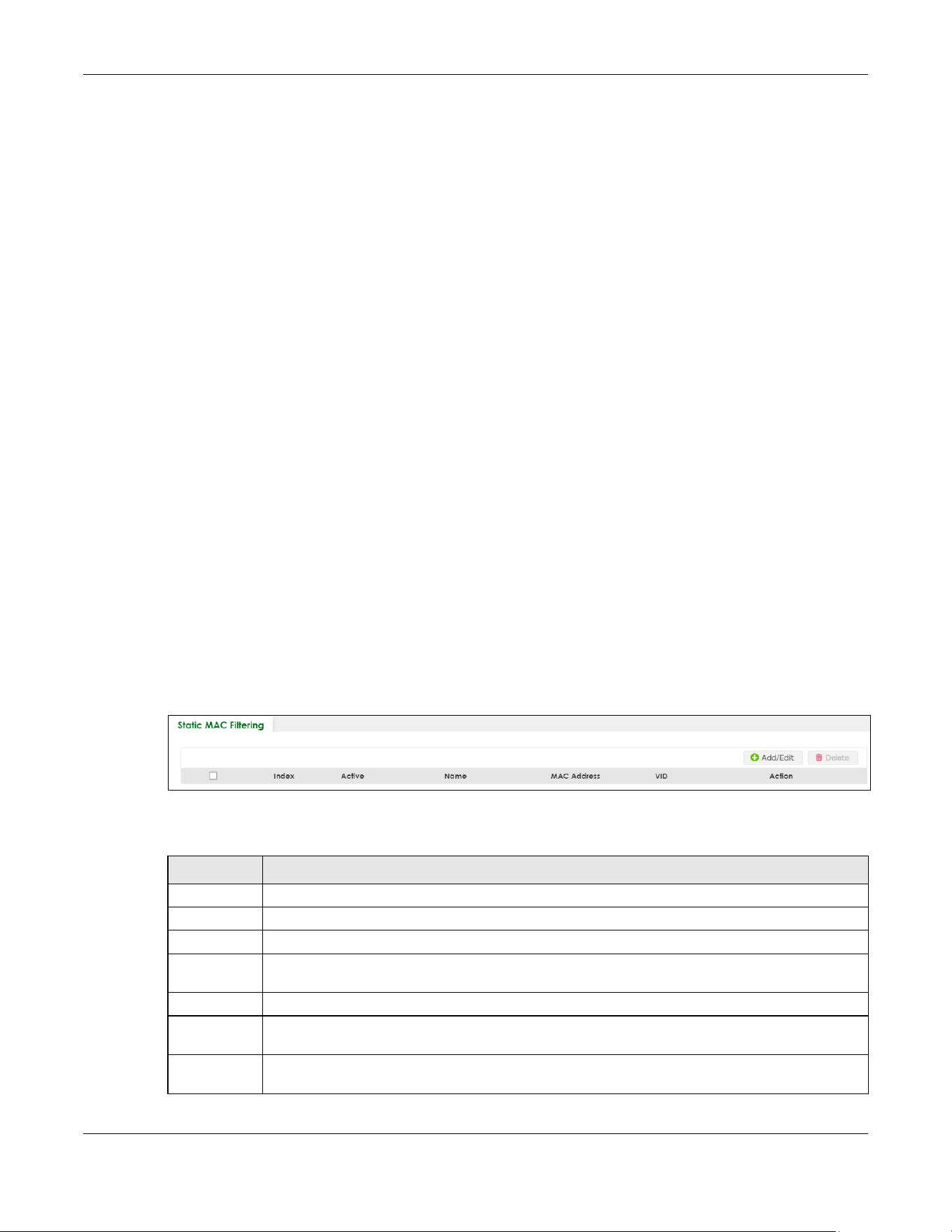
Chapter 55 Static MAC Filtering
XGS2220 Series User’s Guide
410
CHAPTER 55
Static MAC Filtering
55.1 Static MAC Filtering Overview
This chapter discusses MAC address port filtering.
Filtering means sifting traffic going through the Switch based on the source and/or destination MAC
addresses and VLAN group (ID).
55.1.1 What You Can Do
Use the Static MAC Filtering screen (Section 55.2 on page 410) to create rules for traffic going through
the Switch.
55.2 Configure a Static MAC Filtering Rule
Use this screen to view and configure rules for traffic going through the Switch. Click SWITCHING > Static
MAC Filtering in the navigation panel to display the screen as shown next.
Figure 317 SWITCHING > Static MAC Filtering
The following table describes the related labels in this screen.
Table 199 SWITCHING > Static MAC Filtering
LABEL DESCRIPTION
Index This field displays the index number of the rule.
Active This field displays whether the rule is activated or not.
Name This field displays the descriptive name for this rule. This is for identification purpose only.
MAC Address This field displays the source or destination MAC address with the VLAN identification number to
which the MAC address belongs.
VID This field displays the VLAN group identification number.
Action This field displays Discard source, Discard destination, or Discard both depending on what you
configured above.
Select an entry’s check box to select a specific entry. Otherwise, select the check box in the table
heading row to select all entries.
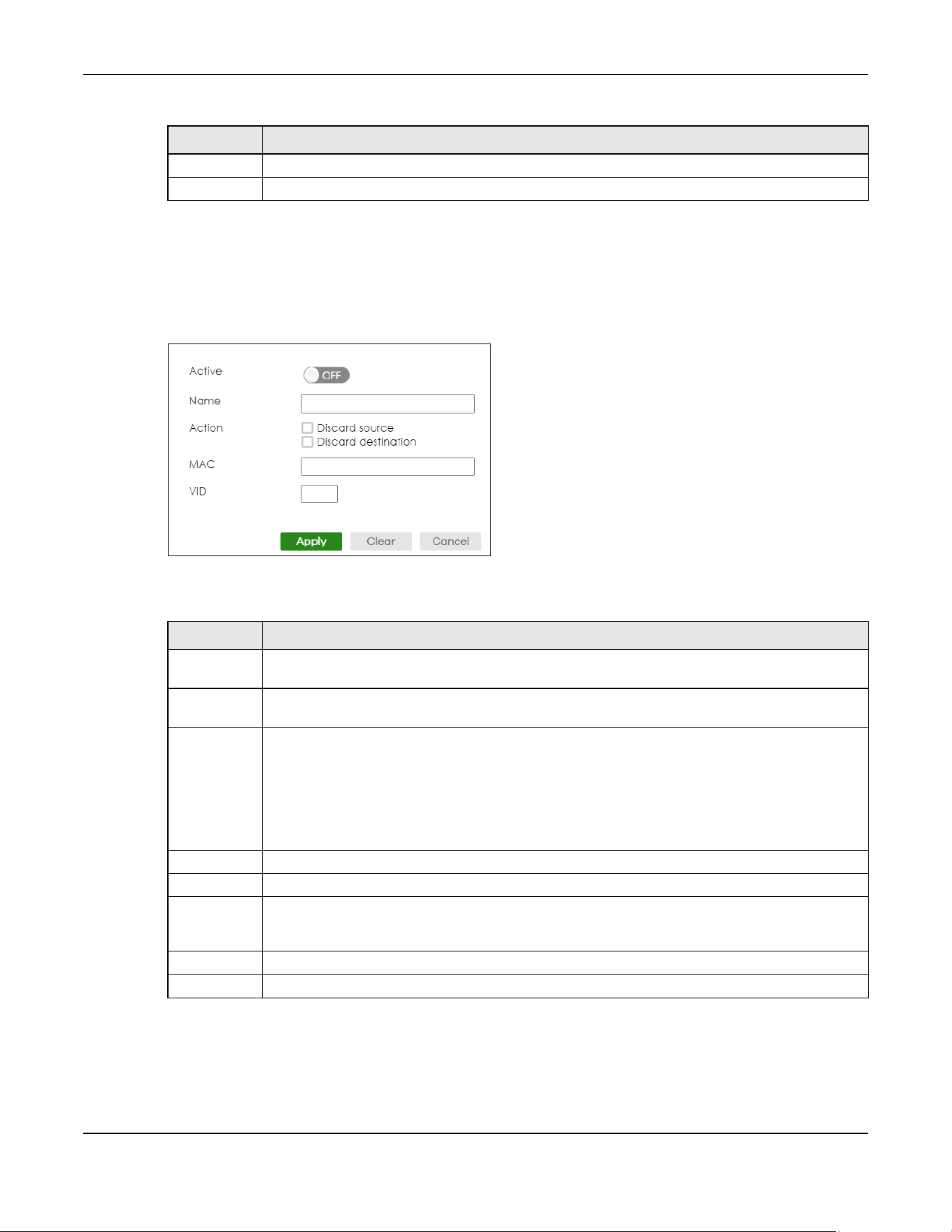
Chapter 55 Static MAC Filtering
XGS2220 Series User’s Guide
411
55.2.1 Add/Edit a Static MAC Filtering Rule
Use this screen to create or edit rules for traffic going through the Switch. Click Add/Edit, or select an
entry and click Add/Edit in the SWITCHING > Static MAC Filtering screen to display this screen.
Figure 318 SWITCHING > Static MAC Filtering > Add/Edit
The following table describes the related labels in this screen.
Add/Edit Click Add/Edit to add a new entry or edit a selected one.
Delete Click Delete to remove the selected entries.
Table 199 SWITCHING > Static MAC Filtering (continued)
LABEL DESCRIPTION
Table 200 SWITCHING > Static MAC Filtering > Add/Edit
LABEL DESCRIPTION
Active Enable the switch button to activate your rule. You may temporarily deactivate a rule without
deleting it by de-selecting this check box.
Name Enter a descriptive name (up to 32 printable ASCII characters excluding [ ? ], [ | ], [ ' ], [ " ] or [ , ]) for
this rule. This is for identification only.
Action Select Discard source to drop the frames from the source MAC address (specified in the MAC field).
The Switch can still send frames to the MAC address.
Select Discard destination to drop the frames to the destination MAC address (specified in the MAC
address). The Switch can still receive frames originating from the MAC address.
Select Discard source and Discard destination to block traffic to or from the MAC address specified
in the MAC field.
MAC Enter a MAC address in valid MAC address format, that is, six hexadecimal character pairs.
VID Enter the VLAN group identification number.
Apply Click Apply to save your changes to the Switch’s run-time memory. The Switch loses these changes
if it is turned off or loses power, so use the Save link on the top navigation panel to save your
changes to the non-volatile memory when you are done configuring.
Clear Click Clear to clear the fields to the factory defaults.
Cancel Click Cancel to not save the configuration you make and return to the last screen.

Chapter 56 Static MAC Forwarding
XGS2220 Series User’s Guide
412
CHAPTER 56
Static MAC Forwarding
56.1 Static MAC Forwarding Overview
This chapter discusses how to configure forwarding rules based on MAC addresses of devices on your
network.
Use these screens to configure static MAC address forwarding.
56.1.1 What You Can Do
Use the Static MAC Forwarding screen (Section 56.2 on page 412) to assign static MAC addresses for a
port.
56.2 Configure Static MAC Forwarding
A static MAC address is an address that has been manually entered in the MAC address table. Static
MAC addresses do not age out. When you set up static MAC address rules, you are setting static MAC
addresses for a port. This may reduce the need for broadcasting.
Click SWITCHING > Static MAC Forwarding in the navigation panel to display the configuration screen as
shown.
Figure 319 SWITCHING > Static MAC Forwarding
The following table describes the labels in this screen.
Table 201 SWITCHING > Static MAC Forwarding
LABEL DESCRIPTION
Index This is the index number of a static MAC address rule.
Active This field displays whether this static MAC address forwarding rule is active. You may temporarily
deactivate a rule without deleting it.
Name This field displays the descriptive name for identification purposes for this static MAC address-
forwarding rule.

Chapter 56 Static MAC Forwarding
XGS2220 Series User’s Guide
413
56.2.1 Add/Edit Static MAC Forwarding Rules
Click Add/Edit, or select an entry and click Add/Edit in the SWITCHING > Static MAC Forwarding screen
to display this screen.
Figure 320 SWITCHING > Static MAC Forwarding > Add/Edit (Standalone Mode)
Figure 321 Switching > Static MAC Forwarding > Add/Edit (Stacking Mode)
MAC Address This field displays the MAC address that will be forwarded and the VLAN identification number to
which the MAC address belongs.
VID This field displays the ID number of the VLAN group.
Port This field displays the port where the MAC address shown in the next field will be forwarded.
In Stacking mode, the first number represents the slot ID and the second is the port number.
Select an entry’s check box to select a specific entry. Otherwise, select the check box in the table
heading row to select all entries.
Add/Edit Click Add/Edit to add a new rule or edit a selected one.
Delete Click Delete to remove the selected rules.
Table 201 SWITCHING > Static MAC Forwarding (continued)
LABEL DESCRIPTION
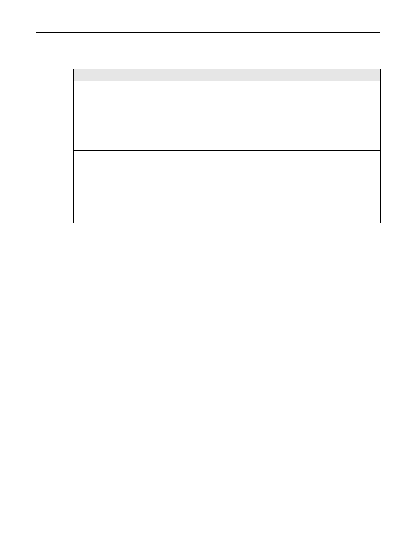
Chapter 56 Static MAC Forwarding
XGS2220 Series User’s Guide
414
The following table describes the labels in this screen.
Table 202 SWITCHING > Static MAC Forwarding > Add/Edit
LABEL DESCRIPTION
Active Enable the switch button to activate your rule. You may temporarily deactivate a rule without
deleting it by disabling the switch.
Name Enter a descriptive name for identification purposes for this static MAC address forwarding rule.
You can enter up to 32 printable ASCII characters except [ ? ], [ | ], [ ' ], [ " ] or [ , ].
MAC Address Enter the MAC address in valid MAC address format, that is, six hexadecimal character pairs.
Note: Static MAC addresses do NOT age out.
VID Enter the VLAN identification number.
Port Enter the port where the MAC address entered in the previous field will be automatically
forwarded.
In Stacking mode, the first box field is the slot ID and the second field is the port number.
Apply Click Apply to save your changes to the Switch’s run-time memory. The Switch loses these
changes if it is turned off or loses power, so use the Save link on the top navigation panel to save
your changes to the non-volatile memory when you are done configuring.
Clear Click Clear to clear the fields to the factory defaults.
Cancel Click Cancel to not save the configuration you make and return to the last screen.

XGS2220 Series User’s Guide
415
CHAPTER 57
VLAN
57.1 VLAN Overview
This chapter shows you how to configure 802.1Q tagged and port-based VLANs.
The type of screen you see here depends on the VLAN Type you selected in the SYSTEM > Switch Setup
screen which is only available in standalone mode. The Switch does not support port-based VLANs in
Stacking mode.
57.1.1 What You Can Do
• Use the VLAN Status screen (Section 57.3 on page 418) to view and search all static VLAN groups.
• Use the VLAN Status Details screen (Section 57.3.1 on page 419) to view detailed port settings and
status of the static VLAN group.
• Use the Static VLAN Setup screen (Section 57.4 on page 421) to configure a static VLAN for the Switch.
• Use the VLAN Port Setup screen (Section 57.5 on page 423) to configure the static VLAN (IEEE 802.1Q)
settings on a port.
• Use the GVRP screen (Section 57.6 on page 425) to enable/disable GVRP on each port.
• Use the Subnet Based VLAN Setup screen (Section 57.8 on page 428) to set up VLANs that allow you to
group traffic into logical VLANs based on the source IP subnet you specify.
• Use the Protocol Based VLAN Setup screen (Section 57.9 on page 430) to set up VLANs that allow you
to group traffic into logical VLANs based on the protocol you specify.
• Use the Voice VLAN Setup screen (Section 57.11 on page 433) to set up VLANs that allow you to group
voice traffic with defined priority and enable the Switch port to carry the voice traffic separately from
data traffic to ensure the sound quality does NOT deteriorate.
• Use the MAC Based VLAN Setup screen (Section 57.12 on page 435) to set up VLANs that allow you to
group untagged packets into logical VLANs based on the source MAC address of the packet. This
eliminates the need to reconfigure the Switch when you change ports. The Switch will forward the
packets based on the source MAC address you set up previously.
• Use the Vendor ID Based VLAN Setup screen (Section 57.13 on page 437) to set up VLANs that allow
you to group untagged packets into logical VLANs based on the source MAC address of the packet.
You can specify a mask for the MAC address to create a MAC address filter and enter a weight to set
the VLAN rule’s priority.
57.1.2 What You Need to Know
Read this section to know more about VLAN and how to configure the screens.

Chapter 57 VLAN
XGS2220 Series User’s Guide
416
57.2 Introduction to IEEE 802.1Q Tagged VLANs
A tagged VLAN uses an explicit tag (VLAN ID) in the MAC header to identify the VLAN membership of a
frame across bridges
– they are not confined to the switch on which they were created. The VLANs can
be created statically by hand or dynamically through GVRP. The VLAN ID associates a frame with a
specific VLAN and provides the information that switches need to process the frame across the network.
A tagged frame is 4 bytes longer than an untagged frame and contains 2 bytes of TPID (Tag Protocol
Identifier, residing within the type or length field of the Ethernet frame) and 2 bytes of TCI (Tag Control
Information, starts after the source address field of the Ethernet frame).
The CFI (Canonical Format Indicator) is a single-bit flag, always set to zero for Ethernet switches. If a
frame received at an Ethernet port has a CFI set to 1, then that frame should not be forwarded as it is to
an untagged port. The remaining twelve bits define the VLAN ID, giving a possible maximum number of
4096 VLANs. Note that user priority and VLAN ID are independent of each other. A frame with VID (VLAN
Identifier) of null (0) is called a priority frame, meaning that only the priority level is significant and the
default VID of the ingress port is given as the VID of the frame. Of the 4096 possible VIDs, a VID of 0 is
used to identify priority frames and value 4095 (FFF) is reserved, so the maximum possible VLAN
configurations are 4094.
Forwarding Tagged and Untagged Frames
Each port on the Switch is capable of passing tagged or untagged frames. To forward a frame from an
802.1Q VLAN-aware switch to an 802.1Q VLAN-unaware switch, the Switch first decides where to
forward the frame and then strips off the VLAN tag. To forward a frame from an 802.1Q VLAN-unaware
switch to an 802.1Q VLAN-aware switch, the Switch first decides where to forward the frame, and then
inserts a VLAN tag reflecting the ingress port's default VID. The default PVID is VLAN 1 for all ports, but this
can be changed.
A broadcast frame (or a multicast frame for a multicast group that is known by the system) is duplicated
only on ports that are members of the VID (except the ingress port itself), thus confining the broadcast to
a specific domain.
57.2.0.1 Automatic VLAN Registration
GARP and GVRP are the protocols used to automatically register VLAN membership across switches.
GARP
GARP (Generic Attribute Registration Protocol) allows network switches to register and de-register
attribute values with other GARP participants within a bridged LAN. GARP is a protocol that provides a
generic mechanism for protocols that serve a more specific application, for example, GVRP.
GARP Timers
Switches join VLANs by making a declaration. A declaration is made by issuing a Join message using
GARP. Declarations are withdrawn by issuing a Leave message. A Leave All message terminates all
registrations. GARP timers set declaration timeout values.
TPID
16 Bits
User Priority
3 Bits
CFI
1 Bit
VLAN ID
12 Bits

Chapter 57 VLAN
XGS2220 Series User’s Guide
417
GVRP
GVRP (GARP VLAN Registration Protocol) is a registration protocol that defines a way for switches to
register necessary VLAN members on ports across the network. Enable this function to permit VLAN
groups beyond the local Switch.
Please refer to the following table for common IEEE 802.1Q VLAN terminology.
57.2.0.2 Port VLAN Trunking
Enable VLAN Trunking on a port to allow frames belonging to unknown VLAN groups to pass through
that port. This is useful if you want to set up VLAN groups on end devices without having to configure the
same VLAN groups on intermediary devices.
Refer to the following figure. Suppose you want to create VLAN groups 1 and 2 (V1 and V2) on devices
A and B. Without VLAN Trunking, you must configure VLAN groups 1 and 2 on all intermediary switches C,
D and E; otherwise they will drop frames with unknown VLAN group tags. However, with VLAN Trunking
enabled on ports in each intermediary switch you only need to create VLAN groups in the end devices
(A and B). C, D and E automatically allow frames with VLAN group tags 1 and 2 (VLAN groups that are
unknown to those switches) to pass through their VLAN trunking ports.
Figure 322 Port VLAN Trunking
Table 203 IEEE 802.1Q VLAN Terminology
VLAN PARAMETER TERM DESCRIPTION
VLAN Type Permanent VLAN This is a static VLAN created manually.
Dynamic VLAN This is a VLAN configured by a GVRP registration or de-registration
process.
VLAN Administrative
Control
Registration Fixed Fixed registration ports are permanent VLAN members.
Registration
Forbidden
Ports with registration forbidden are forbidden to join the specified
VLAN.
Normal Registration Ports dynamically join a VLAN using GVRP.
VLAN Tag Control Tagged Ports belonging to the specified VLAN tag all outgoing frames
transmitted.
Untagged Ports belonging to the specified VLAN do not tag all outgoing
frames transmitted.
VLAN Port Port VID This is the VLAN ID assigned to untagged frames that this port
received.
Acceptable Frame
Type
You may choose to accept both tagged and untagged incoming
frames, just tagged incoming frames or just untagged incoming
frames on a port.
Ingress filtering If set, the Switch discards incoming frames for VLANs that do not
have this port as a member.
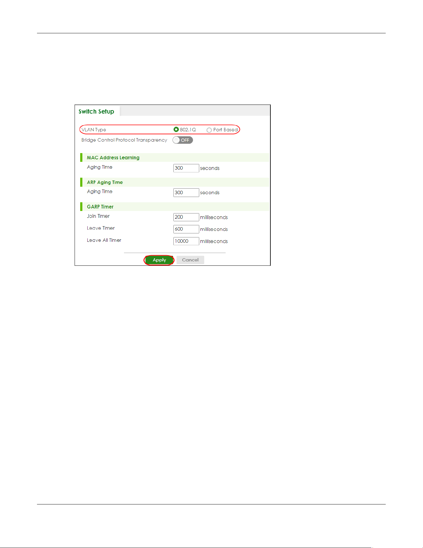
Chapter 57 VLAN
XGS2220 Series User’s Guide
418
57.2.0.3 Select the VLAN Type
Select a VLAN type in the SYSTEM > Switch Setup screen.
Note: VLAN Type is not applicable in stacking mode.
Figure 323 SYSTEM > Switch Setup: Select VLAN Type (With Access L3 License)
802.1Q Static VLAN
Make sure 802.1Q is selected in the SYSTEM > Switch Setup screen.
Use a static VLAN to decide whether an incoming frame on a port should be
• sent to a VLAN group as normal depending on its VLAN tag.
• sent to a group whether it has a VLAN tag or not.
• blocked from a VLAN group regardless of its VLAN tag.
You can also tag all outgoing frames (that were previously untagged) from a port with the specified
VID.
57.3 VLAN Status
Use this screen to view and search all static VLAN groups. Click SWITCHING > VLAN > VLAN Status from
the navigation panel to display the screen as shown next.

Chapter 57 VLAN
XGS2220 Series User’s Guide
419
Figure 324 SWITCHING > VLAN > VLAN Status
The following table describes the labels in this screen.
57.3.1 VLAN Details
Use this screen to view detailed port settings and status of the static VLAN group. Click an index number
in the VLAN Status screen to display VLAN details.
Table 204 SWITCHING > VLAN > VLAN Status
LABEL DESCRIPTION
VLAN Search by
VID
Enter (an) existing VLAN ID numbers (use a comma (,) to separate individual VLANs or a hyphen
(-) to indicate a range of VLANs. For example, “3,4” or “3-9”) and click Search to display only the
specified VLANs in the list below.
Leave this field blank and click Search to display all VLANs configured on the Switch.
The Number of
VLAN
This is the number of VLANs configured on the Switch.
The Number of
Search Results
This is the number of VLANs that match the searching criteria and display in the list below.
This field displays only when you use the Search button to look for certain VLANs.
Index This is the VLAN index number. Click an index number to view more VLAN details.
VID This is the VLAN identification number that was configured in the corresponding VLAN
configuration screen.
Name This fields shows the descriptive name of the VLAN.
Tagged Port This field shows the tagged ports that are participating in the VLAN.
Untagged Port This field shows the untagged ports that are participating in the VLAN.
Elapsed Time This field shows how long it has been since a normal VLAN was registered or a static VLAN was
set up.
Status This field shows how this VLAN was added to the Switch.
• Dynamic – using GVRP
• Static – added as a permanent VLAN
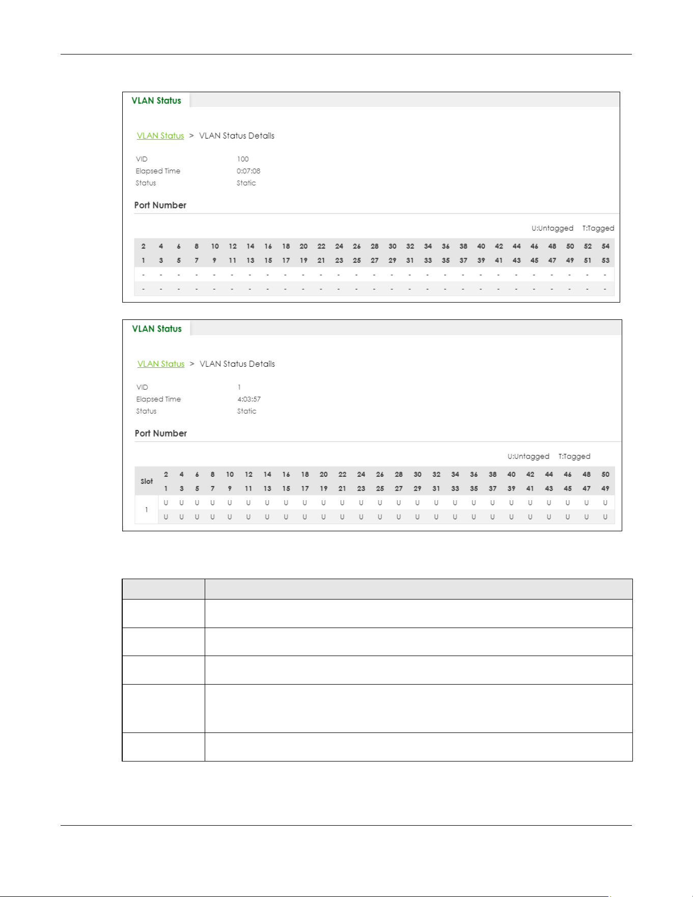
Chapter 57 VLAN
XGS2220 Series User’s Guide
420
Figure 325 SWITCHING > VLAN > VLAN Status > VLAN Status Details (Standalone Mode)
Figure 326 SWITCHING > VLAN > VLAN Status > VLAN Status Details (Stacking Mode)
The following table describes the labels in this screen.
Table 205 SWITCHING > VLAN > VLAN Status > VLAN Status Details
LABEL DESCRIPTION
VID This is the VLAN identification number that was configured in the corresponding VLAN
configuration screen.
Slot ‘Slot’ refers to a Switch in the ‘virtual chassis’ stack. This field displays the slot ID of the stacked
Switch.
Elapsed Time This field shows how long it has been since a normal VLAN was registered or a static VLAN was
set up.
Status This field shows how this VLAN was added to the Switch.
• Dynamic: using GVRP
• Static: added as a permanent entry
Port Number This section displays the ports that are participating in a VLAN. A tagged port is marked as T, an
untagged port is marked as U and ports not participating in a VLAN are marked as “–“.

Chapter 57 VLAN
XGS2220 Series User’s Guide
421
57.4 Configure a Static VLAN
Use this screen to view and configure a static VLAN for the Switch. Click SWITCHING > VLAN > VLAN
Setup > Static VLAN to display the screen as shown next.
Figure 327 SWITCHING > VLAN > VLAN Setup > Static VLAN
The following table describes the related labels in this screen.
57.4.1 Add/Edit a Static VLAN
Use this screen to configure a static VLAN for the Switch. Click Add/Edit, or select an entry and click
Add/Edit in the SWITCHING > VLAN > VLAN Setup > Static VLAN screen to display this screen.
Table 206 SWITCHING > VLAN > VLAN Setup > Static VLAN
LABEL DESCRIPTION
VID This field displays the ID number of the VLAN group.
Active This field indicates whether the VLAN settings are enabled or disabled.
Name This field displays the descriptive name for this VLAN group.
Select an entry’s check box to select a specific entry. Otherwise, select the check box in the
table heading row to select all entries.
Add/Edit Click Add/Edit to add a new static VLAN or edit a selected one.
Delete Click Delete to remove the selected static VLAN.
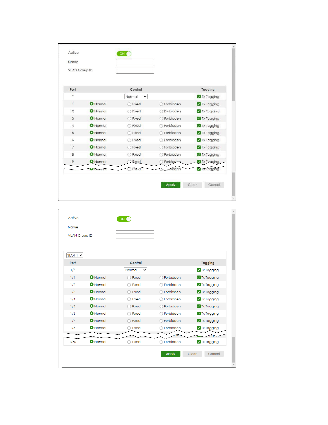
Chapter 57 VLAN
XGS2220 Series User’s Guide
422
Figure 328 SWITCHING > VLAN > VLAN Setup > Static VLAN > Add/Edit (Standalone Mode)
Figure 329 SWITCHING > VLAN > VLAN Setup > Static VLAN > Add/Edit (Static Mode)

Chapter 57 VLAN
XGS2220 Series User’s Guide
423
The following table describes the related labels in this screen.
57.5 VLAN Port Setup
Use this screen to configure the static VLAN (IEEE 802.1Q) settings on a port. Click SWITCHING > VLAN >
VLAN Setup > VLAN Port Setup to display the screen as shown.
Table 207 SWITCHING > VLAN > VLAN Setup > Static VLAN > Add/Edit
LABEL DESCRIPTION
Active Enable the switch button to activate the VLAN settings.
Name Enter a descriptive name for the VLAN group for identification purposes. This name consists of up
to 64 printable ASCII characters. The string should not contain [ ? ], [ | ], [ ' ], [ " ] or [ , ].
VLAN Group ID Enter the VLAN ID for this static entry; the valid range is between 1 and 4094.
Note: Do NOT add a VLAN ID that has been used in the SWITCHING > VLAN > Voice
VLAN Setup.
SLOT This field appears only in Stacking mode. Click the drop-down list to choose the slot number of
the Switch in a stack.
Port The port number identifies the port you are configuring. In Stacking mode, the first number
represents the slot ID and the second one is the port number. Please note that the default
stacking ports (the last four ports of your Switch) cannot be configured. They are reserved for
stacking only.
* Settings in this row apply to all ports.
Use this row only if you want to make some settings the same for all ports. Use this row first to set
the common settings and then make adjustments on a port-by-port basis.
Note: Changes in this row are copied to all the ports as soon as you make them.
Control Select Normal for the port to dynamically join this VLAN group using GVRP. This is the default
selection.
Select Fixed for the port to be a permanent member of this VLAN group.
Select Forbidden if you want to prohibit the port from joining this VLAN group.
Tagging Select Tx Tagging if you want the port to tag all outgoing frames transmitted with this VLAN
Group ID.
Apply Click Apply to save your changes to the Switch’s run-time memory. The Switch loses these
changes if it is turned off or loses power, so use the Save link on the top navigation panel to save
your changes to the non-volatile memory when you are done configuring.
Clear Click Clear to clear the fields to the factory defaults.
Cancel Click Cancel to not save the configuration you make and return to the last screen.
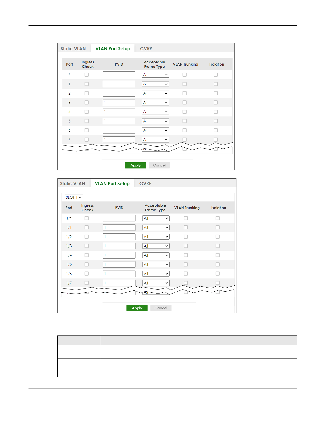
Chapter 57 VLAN
XGS2220 Series User’s Guide
424
Figure 330 SWITCHING > VLAN > VLAN Setup > VLAN Port Setup (Standalone Mode)
Figure 331 SWITCHING > VLAN > VLAN Setup > VLAN Port Setup (Stacking Mode)
The following table describes the labels in this screen.
Table 208 SWITCHING > VLAN > VLAN Setup > VLAN Port Setup
LABEL DESCRIPTION
SLOT This field appears only in stacking mode. Click the drop-down list to choose the slot number of
the Switch in a stack.
Port This field displays the port number of the Switch. In Stacking mode, the first number represents
the slot ID and the second is the port number. Please note that the default stacking ports (the
last four ports of your Switch) cannot be configured. They are reserved for stacking only.

Chapter 57 VLAN
XGS2220 Series User’s Guide
425
57.6 Configure GVRP
Use this screen to configure GVRP settings on a port. Click SWITCHING > VLAN > VLAN Setup > GVRP to
display the screen as shown.
* Settings in this row apply to all ports.
Use this row only if you want to make some settings the same for all ports. Use this row first to set
the common settings and then make adjustments on a port-by-port basis.
Note: Changes in this row are copied to all the ports as soon as you make them.
Ingress Check If this check box is selected, the Switch discards incoming frames on a port for VLANs that do
not include this port in its member set.
Clear this check box to disable ingress filtering.
PVID A PVID (Port VLAN ID) is a tag that adds to incoming untagged frames received on a port so
that the frames are forwarded to the VLAN group that the tag defines.
Enter a number between 1and 4094 as the port VLAN ID.
Acceptable
Frame Type
Specify the type of frames allowed on a port. Choices are All, Tag Only and Untag Only.
Select All from the drop-down list box to accept all untagged or tagged frames on this port.
This is the default setting.
Select Tag Only to accept only tagged frames on this port. All untagged frames will be
dropped.
Select Untag Only to accept only untagged frames on this port. All tagged frames will be
dropped.
Note: When the Switch is in Stacking mode and the master Switch has VLAN1, all
other ports will be configured to untagged port.
VLAN Trunking Enable VLAN Trunking on ports connected to other switches or routers (but not ports directly
connected to end users) to allow frames belonging to unknown VLAN groups to pass through
the Switch.
Isolation Select this to allows this port to communicate only with the CPU management port and the
ports on which the isolation feature is NOT enabled.
Apply Click Apply to save your changes to the Switch’s run-time memory. The Switch loses these
changes if it is turned off or loses power, so use the Save link on the top navigation panel to
save your changes to the non-volatile memory when you are done configuring.
Cancel Click Cancel to begin configuring this screen afresh.
Table 208 SWITCHING > VLAN > VLAN Setup > VLAN Port Setup (continued)
LABEL DESCRIPTION
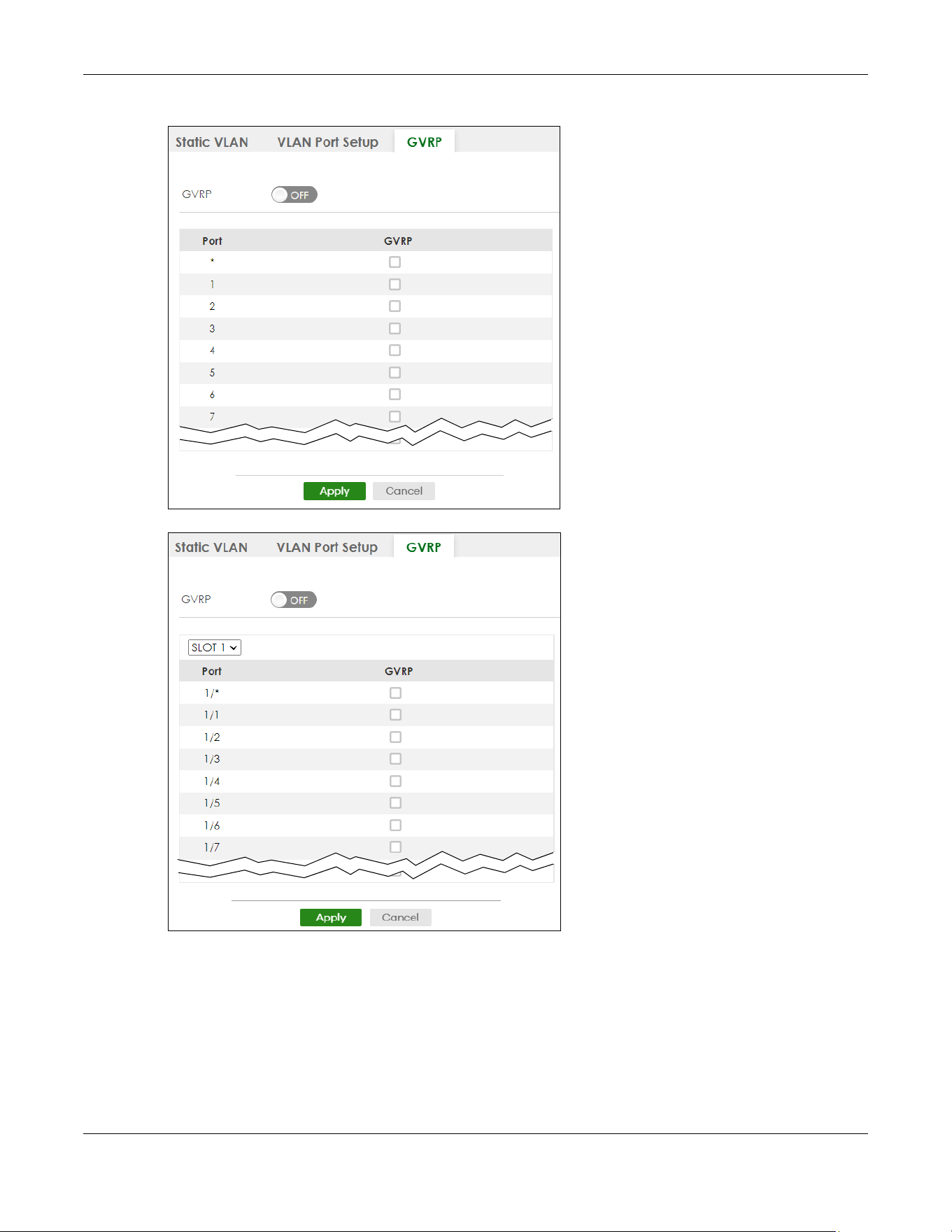
Chapter 57 VLAN
XGS2220 Series User’s Guide
426
Figure 332 SWITCHING > VLAN > VLAN Setup > GVRP (Standalone Mode)
Figure 333 SWITCHING > VLAN > VLAN Setup > GVRP (Stacking Mode)

Chapter 57 VLAN
XGS2220 Series User’s Guide
427
The following table describes the labels in this screen.
57.7 Subnet Based VLAN
Subnet based VLANs allow you to group traffic into logical VLANs based on the source IP subnet you
specify. When a frame is received on a port, the Switch checks if a tag is added already and the IP
subnet it came from. The untagged packets from the same IP subnet are then placed in the same
subnet based VLAN. One advantage of using subnet based VLANs is that priority can be assigned to
traffic from the same IP subnet.
Note: Subnet based VLAN applies to un-tagged packets and is applicable only when you use
IEEE 802.1Q tagged VLAN.
For example, an ISP (Internet Services Provider) may divide different types of services it provides to
customers into different IP subnets. Traffic for voice services is designated for IP subnet 172.16.1.0/24,
video for 192.168.1.0/24 and data for 10.1.1.0/24. The Switch can then be configured to group incoming
traffic based on the source IP subnet of incoming frames.
You configure a subnet based VLAN with priority 6 and VID of 100 for traffic received from IP subnet
172.16.1.0/24 (voice services). You also have a subnet based VLAN with priority 5 and VID of 200 for
traffic received from IP subnet 192.168.1.0/24 (video services). Lastly, you configure VLAN with priority 3
and VID of 300 for traffic received from IP subnet 10.1.1.0/24 (data services). All untagged incoming
frames will be classified based on their source IP subnet and prioritized accordingly. That is video
services receive the highest priority and data the lowest.
Table 209 SWITCHING > VLAN > VLAN Setup > GVRP
LABEL DESCRIPTION
GVRP GVRP (GARP VLAN Registration Protocol) is a registration protocol that defines a way for
switches to register necessary VLAN members on ports across the network.
Enable the switch button to permit VLAN groups beyond the local Switch.
SLOT This field appears only in Stacking mode. Click the drop-down list to choose the slot number of
the Switch in a stack.
Port This field displays the port number of the Switch. In Stacking mode, the first number represents
the slot ID and the second is the port number. Please note that the default stacking ports (the
last four ports of your Switch) cannot be configured. They are reserved for stacking only.
* Settings in this row apply to all ports.
Use this row only if you want to make some settings the same for all ports. Use this row first to set
the common settings and then make adjustments on a port-by-port basis.
Note: Changes in this row are copied to all the ports as soon as you make them.
GVRP Select this check box to allow GVRP on this port.
Apply Click Apply to save your changes to the Switch’s run-time memory. The Switch loses these
changes if it is turned off or loses power, so use the Save link on the top navigation panel to
save your changes to the non-volatile memory when you are done configuring.
Cancel Click Cancel to begin configuring this screen afresh.
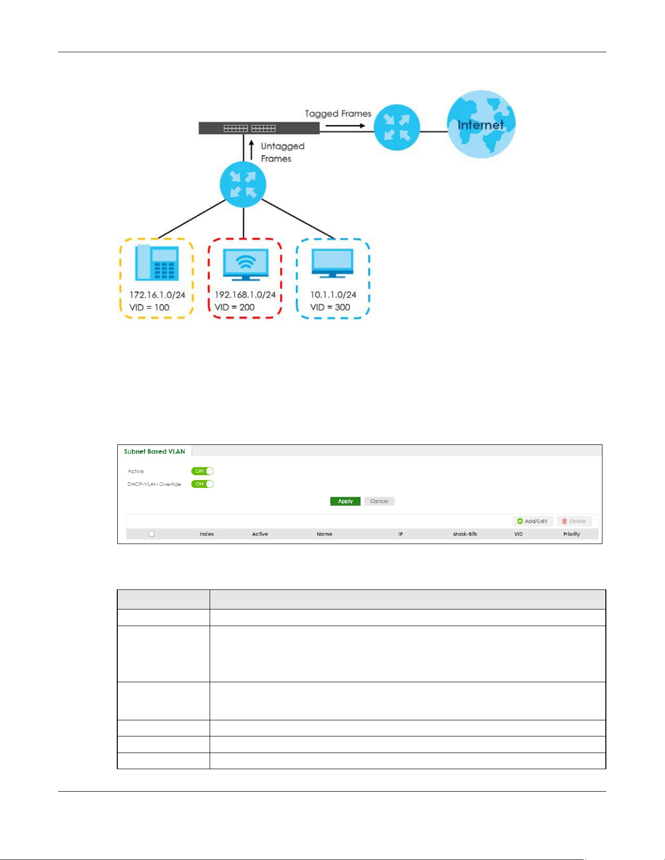
Chapter 57 VLAN
XGS2220 Series User’s Guide
428
Figure 334 Subnet Based VLAN Application Example
57.8 Configuring Subnet Based VLAN
Click the SWITCHING > VLAN > Subnet Based VLAN Setup link in the navigation panel to display the
configuration screen as shown.
Figure 335 SWITCHING > VLAN > Subnet Based VLAN Setup
The following table describes the labels in this screen.
Table 210 SWITCHING > VLAN > Subnet Based VLAN Setup
LABEL DESCRIPTION
Active Enable the switch button to activate this subnet based VLANs on the Switch.
DHCP-VLAN
Override
When DHCP snooping is enabled DHCP clients can renew their IP address through the DHCP
VLAN or through another DHCP server on the subnet based VLAN.
Enable the switch button to force the DHCP clients in this IP subnet to obtain their IP
addresses through the DHCP VLAN.
Apply Click Apply to save your changes to the Switch’s run-time memory. The Switch loses these
changes if it is turned off or loses power, so use the Save link on the top navigation panel to
save your changes to the non-volatile memory when you are done configuring.
Cancel Click Cancel to begin configuring this screen afresh.
Index This is the index number identifying this subnet based VLAN.
Active This field shows whether the subnet based VLAN is active or not.
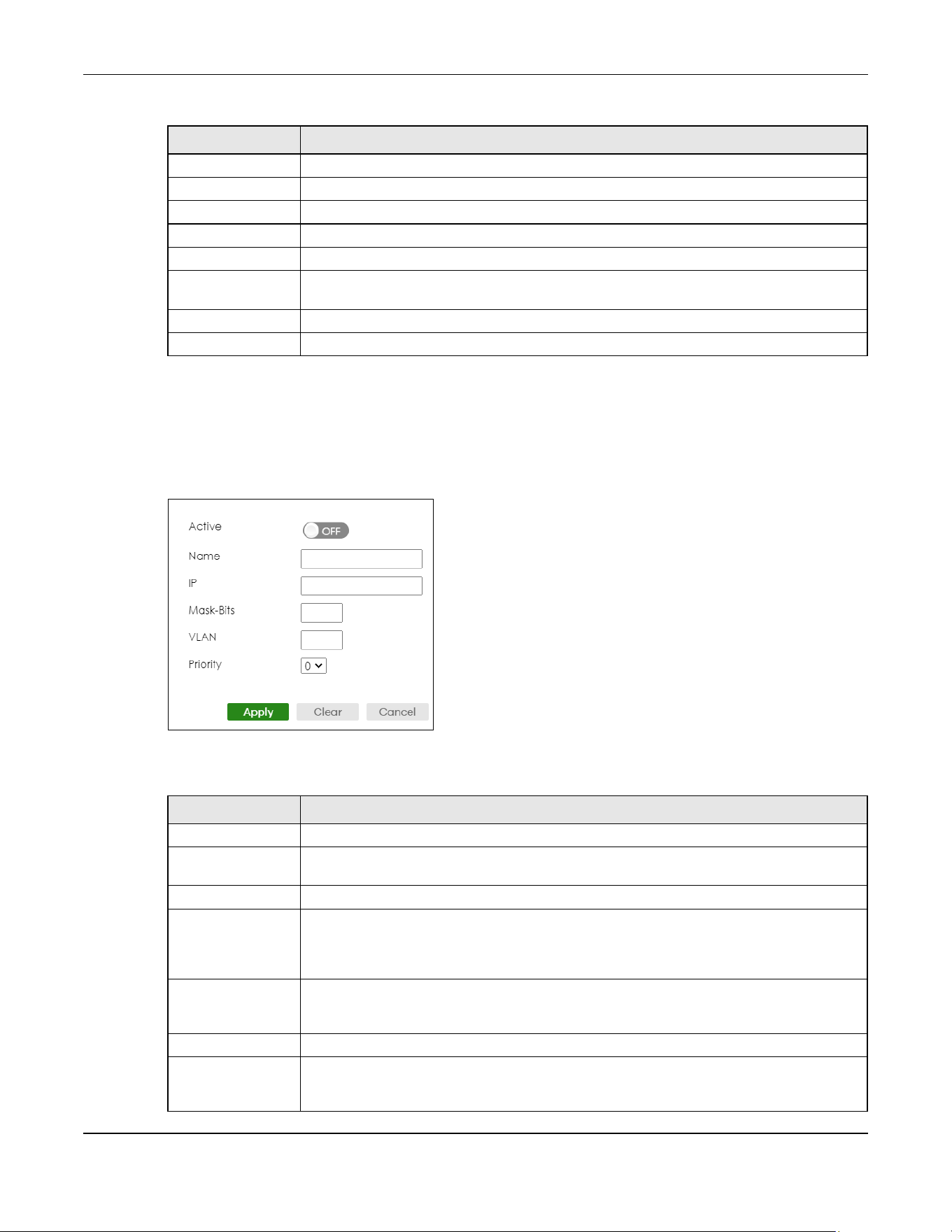
Chapter 57 VLAN
XGS2220 Series User’s Guide
429
57.8.1 Add/Edit Subnet Based VLAN
Click Add/Edit, or select an entry and click Add/Edit in the SWITCHING > VLAN > Subnet Based VLAN
Setup screen to display this screen.
Figure 336 SWITCHING > VLAN > Subnet Based VLAN Setup > Add/Edit
The following table describes the labels in this screen.
Name This field shows the name the subnet based VLAN.
IP This field shows the IP address of the subnet for this subnet based VLAN.
Mask-Bits This field shows the subnet mask in bit number format for this subnet based VLAN.
VID This field shows the VLAN ID of the frames which belong to this subnet based VLAN.
Priority This field shows the priority which is assigned to frames belonging to this subnet based VLAN.
Select an entry’s check box to select a specific entry. Otherwise, select the check box in the
table heading row to select all entries.
Add/Edit Click Add/Edit to add a new entry or edit a selected one.
Delete Click Delete to remove the selected entry.
Table 210 SWITCHING > VLAN > Subnet Based VLAN Setup (continued)
LABEL DESCRIPTION
Table 211 SWITCHING > VLAN > Subnet Based VLAN Setup > Add/Edit
LABEL DESCRIPTION
Active Enable the switch button to activate the IP subnet VLAN you are creating or editing.
Name Enter up to 32 alphanumeric characters to identify this subnet based VLAN. The string should
not contain [ ? ], [ | ], [ ' ], [ " ] or [ , ].
IP Enter the IP address of the subnet for which you want to configure this subnet based VLAN.
Mask-Bits Enter the bit number of the subnet mask. To find the bit number, convert the subnet mask to
binary format and add all the 1’s together. Take “255.255.255.0” for example. 255 converts to
eight 1s in binary. There are three 255s, so add three eights together and you get the bit
number (24).
VLAN Enter the ID of a VLAN with which the untagged frames from the IP subnet specified in this
subnet based VLAN are tagged. This must be an existing VLAN which you defined in the
SWITCHING > VLAN > VLAN Setup > Static VLAN screen.
Priority Select the priority level that the Switch assigns to frames belonging to this VLAN.
Apply Click Apply to save your changes to the Switch’s run-time memory. The Switch loses these
changes if it is turned off or loses power, so use the Save link on the top navigation panel to
save your changes to the non-volatile memory when you are done configuring.

Chapter 57 VLAN
XGS2220 Series User’s Guide
430
57.9 Protocol Based VLAN
Protocol based VLANs allow you to group traffic into logical VLANs based on the protocol you specify.
When an upstream frame is received on a port (configured for a protocol based VLAN), the Switch
checks if a tag is added already and its protocol. The untagged packets of the same protocol are then
placed in the same protocol based VLAN. One advantage of using protocol based VLANs is that priority
can be assigned to traffic of the same protocol.
Note: Protocol-based VLAN applies to un-tagged packets and is applicable only when you
use IEEE 802.1Q tagged VLAN.
For example, port 1, 2, 3 and 4 belong to static VLAN 100, and port 4, 5, 6, 7 belong to static VLAN 120.
You configure a protocol based VLAN A with priority 3 for ARP traffic received on port 1, 2 and 3. You
also have a protocol based VLAN B with priority 2 for Apple Talk traffic received on port 6 and 7. All
upstream ARP traffic from port 1, 2 and 3 will be grouped together, and all upstream Apple Talk traffic
from port 6 and 7 will be in another group and have higher priority than ARP traffic, when they go
through the uplink port to a backbone switch C.
Figure 337 Protocol Based VLAN Application Example
57.10 Configuring Protocol Based VLAN
Click the SWITCHING > VLAN > Protocol Based VLAN Setup link in the navigation panel to display the
configuration screen as shown.
Figure 338 SWITCHING > VLAN > Protocol Based VLAN Setup
Clear Click Clear to clear the fields to the factory defaults.
Cancel Click Cancel to not save the configuration you make and return to the last screen.
Table 211 SWITCHING > VLAN > Subnet Based VLAN Setup > Add/Edit (continued)
LABEL DESCRIPTION
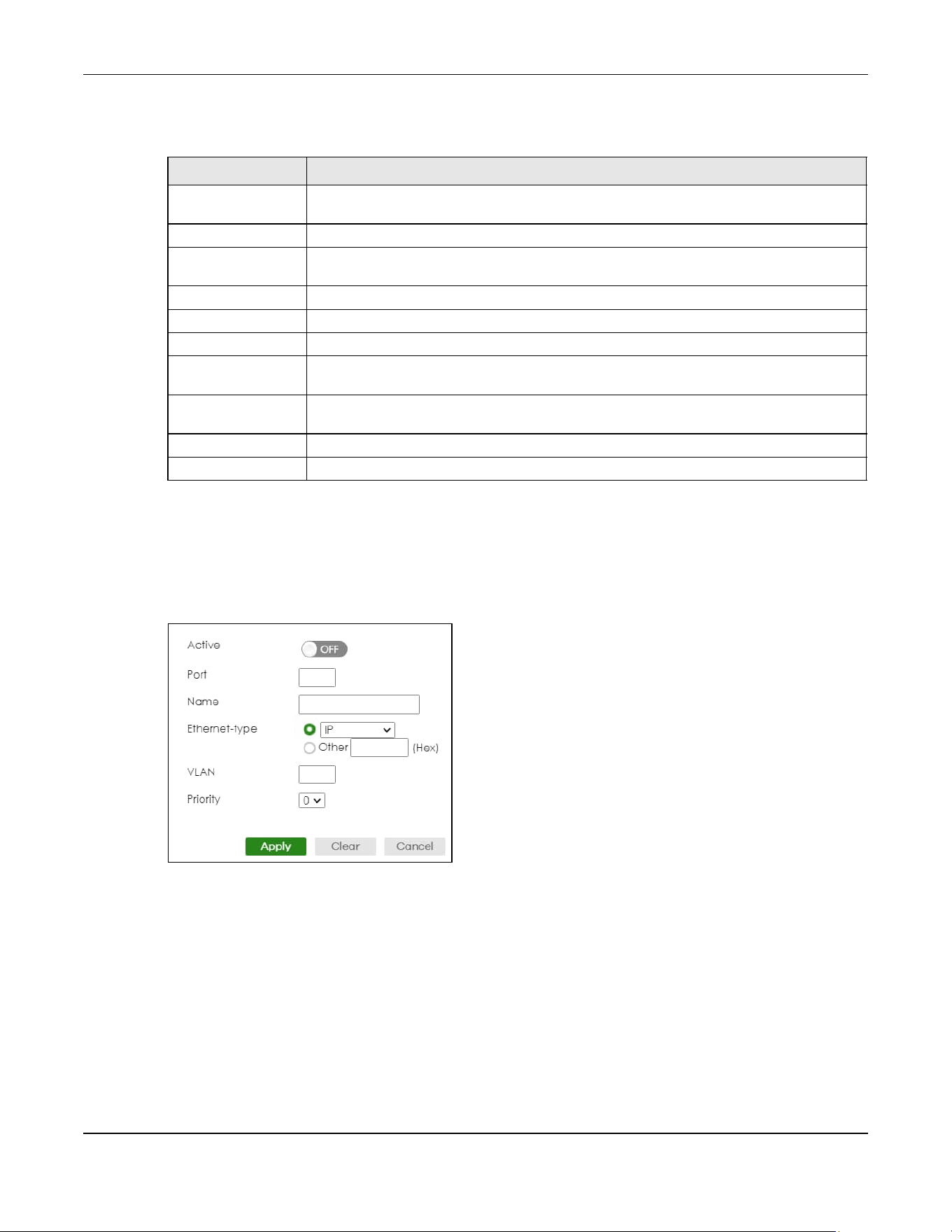
Chapter 57 VLAN
XGS2220 Series User’s Guide
431
The following table describes the labels in this screen.
57.10.1 Add/Edit a Protocol Based VLAN
Click Add/Edit, or select an entry and click Add/Edit in the SWITCHING > VLAN > Protocol Based VLAN
Setup screen to display this configuration screen.
Figure 339 SWITCHING > VLAN > Protocol Based VLAN Setup > Add/Edit (Standalone Mode)
Table 212 SWITCHING > VLAN > Protocol Based VLAN Setup
LABEL DESCRIPTION
Index This is the index number identifying this protocol based VLAN. Click any of these numbers to
edit an existing protocol based VLAN.
Active This field shows whether the protocol based VLAN is active or not.
Port This field shows which port belongs to this protocol based VLAN. In Stacking mode, the first
number represents the slot ID and the second is the port number.
Name This field shows the name of the protocol based VLAN.
Ethernet-type This field shows which Ethernet protocol is part of this protocol based VLAN.
VID This field shows the VLAN ID of the port.
Priority This field shows the priority which is assigned to frames belonging to this protocol based
VLAN.
Select an entry’s check box to select a specific entry. Otherwise, select the check box in
the table heading row to select all entries.
Add/Edit Click Add/Edit to add a new entry or edit a selected one.
Delete Click Delete to remove the selected entry.

Chapter 57 VLAN
XGS2220 Series User’s Guide
432
Figure 340 SWITCHING > VLAN > Protocol Based VLAN Setup > Add/Edit (Stacking Mode)
The following table describes the labels in this screen.
57.10.1.1 Create an IP-based VLAN Example
This example shows you how to create an IP VLAN which includes ports 1, 4 and 8. Follow these steps
using the screen below:
1 Activate this protocol based VLAN.
2 Type the port number you want to include in this protocol based VLAN. Type 1.
3 Give this protocol-based VLAN a descriptive name. Type IP-VLAN.
4 Select the protocol. Leave the default value IP.
Table 213 SWITCHING > VLAN > Protocol Based VLAN Setup > Add/Edit
LABEL DESCRIPTION
Active Enable the switch button to activate this protocol based VLAN.
Port Type a port number to be included in this protocol based VLAN. In Stacking mode, the first
box field is the slot ID and the second field is the port number.
This port must belong to a static VLAN in order to participate in a protocol based VLAN.
Name Enter up to 32 alphanumeric characters to identify this protocol based VLAN. The string
should not contain [ ? ], [ | ], [ ' ], [ " ] or [ , ].
Ethernet-type Use the drop down list box to select a predefined protocol to be included in this protocol
based VLAN or select Other and type the protocol number in hexadecimal notation. For
example the IP protocol in hexadecimal notation is 0800, and Novell IPX protocol is 8137.
Note: Protocols in the hexadecimal number range of 0x0000 to 0x05ff are not
allowed to be used for protocol based VLANs.
VLAN Enter the ID of a VLAN to which the port belongs. This must be an existing VLAN which you
defined in the SWITCHING > VLAN > VLAN Setup > Static VLAN screen.
Priority Select the priority level that the Switch will assign to frames belonging to this VLAN.
Apply Click Apply to save your changes to the Switch’s run-time memory. The Switch loses these
changes if it is turned off or loses power, so use the Save link on the top navigation panel to
save your changes to the non-volatile memory when you are done configuring.
Clear Click Clear to clear the fields to the factory defaults.
Cancel Click Cancel to not save the configuration you make and return to the last screen.
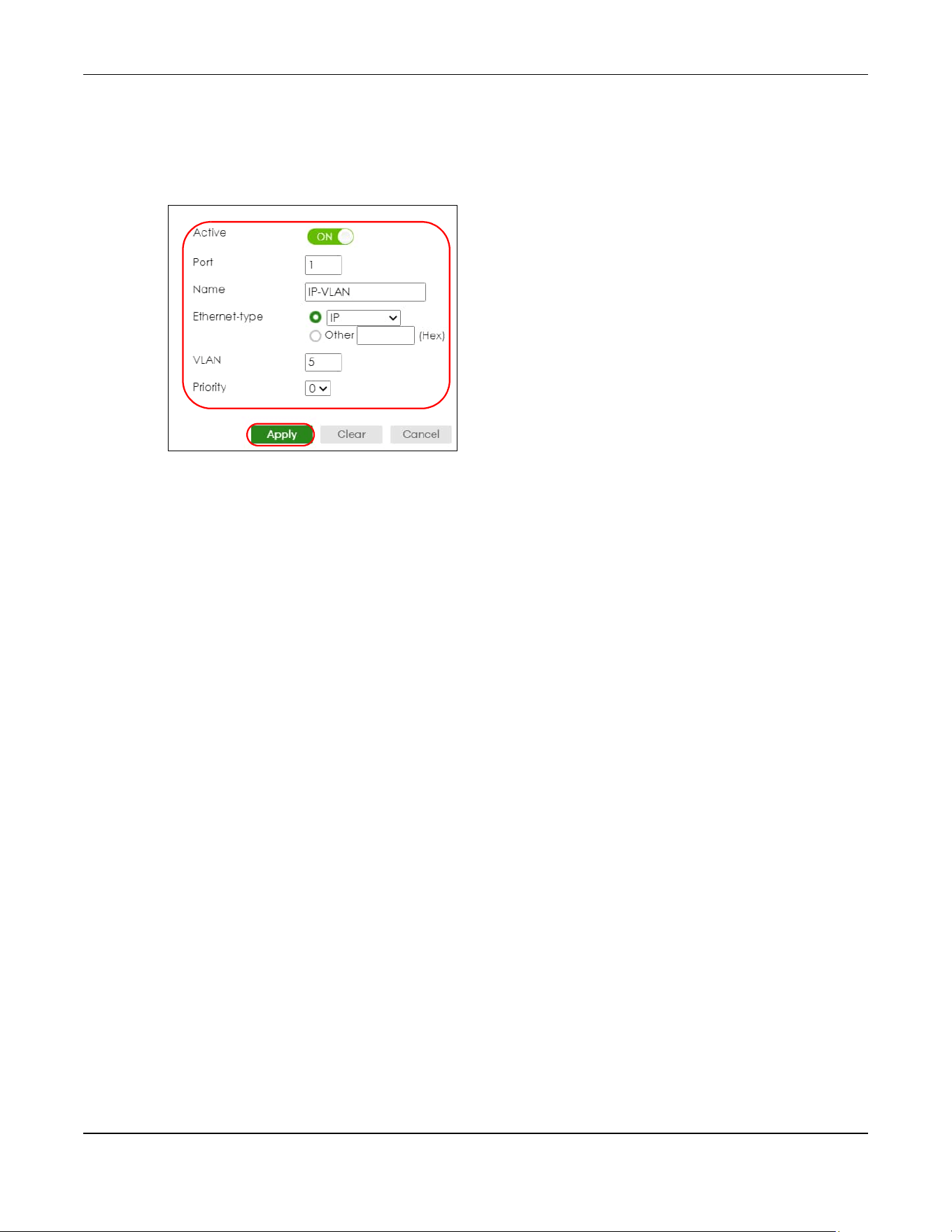
Chapter 57 VLAN
XGS2220 Series User’s Guide
433
5 Type the VLAN ID of an existing VLAN. In our example we already created a static VLAN with an ID of 5.
Type 5.
6 Leave the priority set to 0 and click Apply.
Figure 341 Protocol Based VLAN Configuration Example
To add more ports to this protocol based VLAN.
1 Click the index number of the protocol based VLAN entry. Click 1.
2 Change the value in the Port field to the next port you want to add.
3 Click Apply.
57.11 Voice VLAN
Voice VLAN is a VLAN that is specifically allocated for voice traffic. It ensures that the sound quality of an
IP phone is preserved from deteriorating when the data traffic on the Switch ports is high. It groups the
voice traffic with defined priority into an assigned VLAN which enables the separation of voice and
data traffic coming onto the Switch port.
The Switch can determine whether a received packet is
• an untagged voice packet when the incoming port is a fixed port for voice VLAN.
• a tagged voice packet when the incoming port and VLAN tag belongs to a voice VLAN.
It then checks the source packet’s MAC address against an OUI list. If a match is found, the packet is
considered as a voice packet.
You can set priority level to the Voice VLAN and add MAC address of IP phones from specific
manufacturers by using its ID from the Organizationally Unique Identifiers (OUI).
Click SWITCHING > VLAN > Voice VLAN Setup to display the configuration screen as shown.
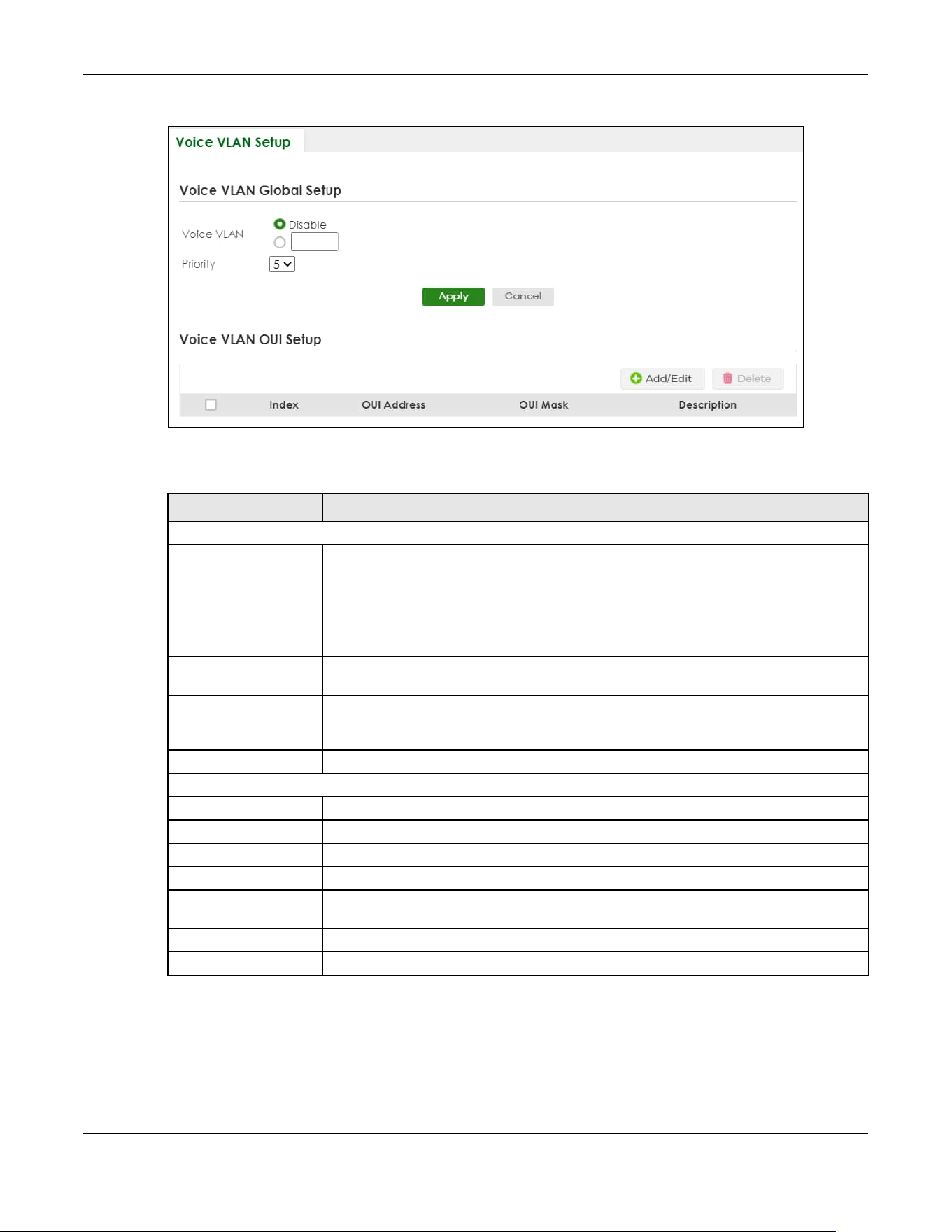
Chapter 57 VLAN
XGS2220 Series User’s Guide
434
Figure 342 SWITCHING > VLAN > Voice VLAN Setup
The following table describes the fields in the above screen.
57.11.1 Add/Edit a Voice VLAN
Click Add/Edit, or select an entry and click Add/Edit in the SWITCHING > VLAN > Voice VLAN Setup
screen to display the configuration screen.
Table 214 SWITCHING > VLAN > Voice VLAN Setup
LABEL DESCRIPTION
Voice VLAN Global Setup
Voice VLAN Click the second radio button if you want to enable the Voice VLAN feature. Enter a
VLAN ID number in the box next to the radio button that is associated with the Voice
VLAN. You also need to create a static VLAN with the same VID in the SWITCHING > VLAN
> VLAN Setup > Static VLAN screen, and then connect the IP phone with the specified
OUI MAC address to a port that joins the static VLAN.
Click Disable radio button if you do not want to enable the Voice VLAN feature.
Priority Select the priority level of the voice traffic from 0 to 7. Default setting is 5. The higher the
numeric value you assign, the higher the priority for this voice traffic.
Apply Click Apply to save your changes to the Switch’s run-time memory. The Switch loses these
changes if it is turned off or loses power, so use the Save link on the top navigation panel
to save your changes to the non-volatile memory when you are done configuring.
Cancel Click Cancel to begin configuring this section afresh.
Voice VLAN OUI Setup
Index This field displays the index number of the Voice VLAN.
OUI Address This field displays the OUI address of the Voice VLAN.
OUI Mask This field displays the OUI mask address of the Voice VLAN.
Description This field displays the description of the Voice VLAN with OUI address.
Select an entry’s check box to select a specific entry. Otherwise, select the check box in
the table heading row to select all entries.
Add/Edit Click Add/Edit to add a new entry or edit a selected one.
Delete Click Delete to remove the selected entry.
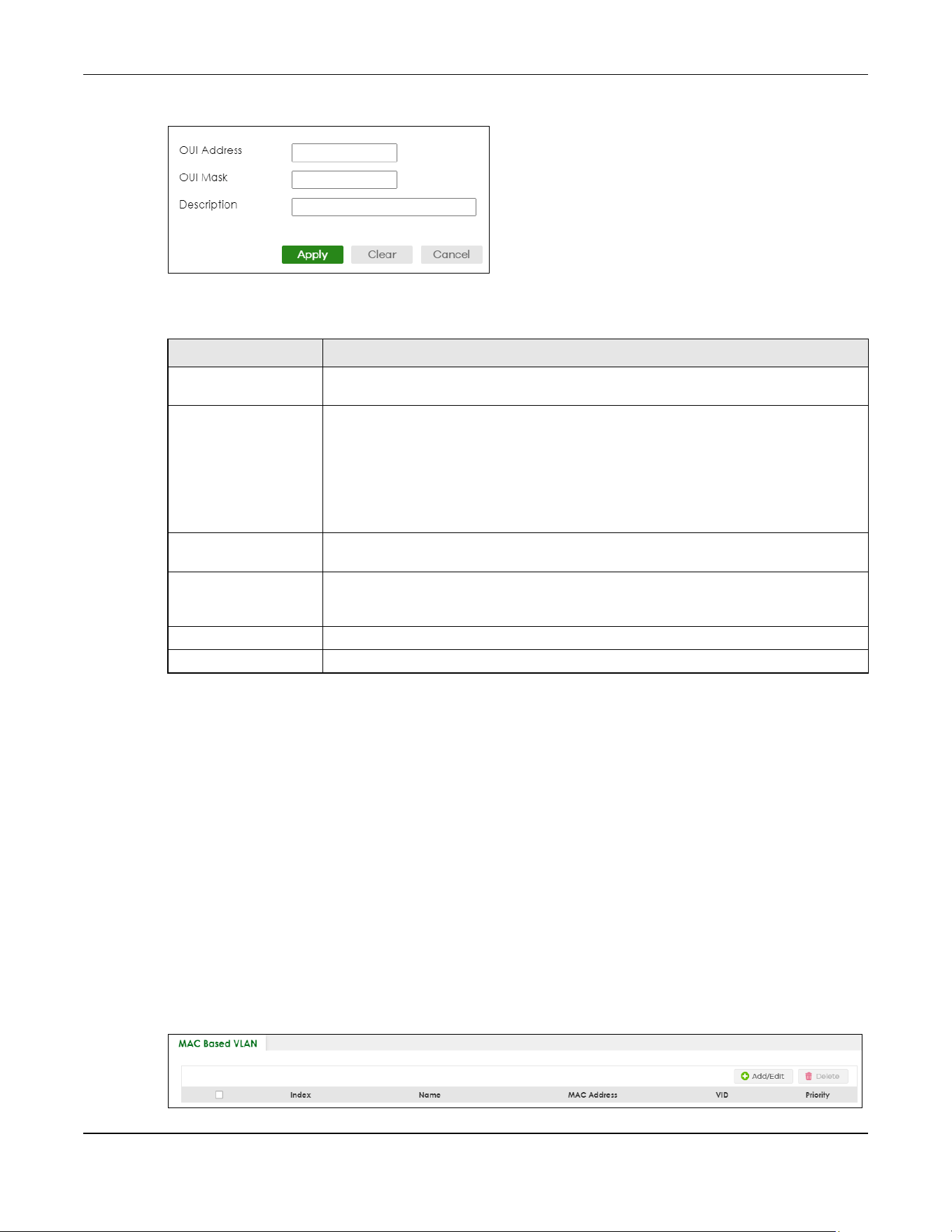
Chapter 57 VLAN
XGS2220 Series User’s Guide
435
Figure 343 SWITCHING > VLAN > Voice VLAN Setup > Add/Edit
The following table describes the fields in the above screen.
57.12 MAC Based VLAN
The MAC-based VLAN feature assigns incoming untagged packets to a VLAN and classifies the traffic
based on the source MAC address of the packet. When untagged packets arrive at the Switch, the
source MAC address of the packet is looked up in a MAC to VLAN mapping table. If an entry is found,
the corresponding VLAN ID is assigned to the packet. The assigned VLAN ID is verified against the VLAN
table. If the VLAN is valid, ingress processing on the packet continues; otherwise, the packet is dropped.
This feature allows users to change ports without having to reconfigure the VLAN. You can assign priority
to the MAC-based VLAN and define a MAC to VLAN mapping table by entering a specified source
MAC address in the MAC-based VLAN setup screen. You can also delete a MAC-based VLAN entry in
the same screen.
Click SWITCHING > VLAN > MAC Based VLAN Setup to see the following screen.
Figure 344 SWITCHING > VLAN > MAC Based VLAN Setup
Table 215 SWITCHING > VLAN > Voice VLAN Setup > Add/Edit
LABEL DESCRIPTION
OUI Address Enter the IP phone manufacturer’s OUI MAC address. The first 3 bytes is the manufacturer
identifier, the last 3 bytes is a unique station ID.
OUI Mask Enter the mask for the specified IP phone manufacturer’s OUI MAC address to determine
which bits a packet’s MAC address should match.
Enter “f” for each bit of the specified MAC address that the traffic’s MAC address should
match. Enter “0” for the bits of the matched traffic’s MAC address, which can be of any
hexadecimal characters. For example, if you set the MAC address to 00:13:49:00:00:00
and the mask to ff:ff:ff:00:00:00, a packet with a MAC address of 00:13:49:12:34:56
matches this criteria.
Description Enter a description up to 32 printable ASCII characters except [ ? ], [ | ], [ ' ], or [ " ] for the
Voice VLAN device. For example: Siemens.
Apply Click Apply to save your changes to the Switch’s run-time memory. The Switch loses these
changes if it is turned off or loses power, so use the Save link on the top navigation panel
to save your changes to the non-volatile memory when you are done configuring.
Clear Click Clear to clear the fields to the factory defaults.
Cancel Click Cancel to not save the configuration you make and return to the last screen.

Chapter 57 VLAN
XGS2220 Series User’s Guide
436
The following table describes the fields in the above screen.
57.12.1 Add/Edit a MAC Based VLAN
Click Add/Edit, or select an entry and click Add/Edit in the SWITCHING > VLAN > MAC Based VLAN Setup
screen to see this screen.
Figure 345 SWITCHING > VLAN > MAC Based VLAN Setup > Add/Edit
The following table describes the fields in the above screen.
Table 216 SWITCHING > VLAN > MAC Based VLAN Setup
LABEL
DESCRIPTION
Index This field displays the index number of the MAC-based VLAN entry.
Name This field displays the name of the MAC-based VLAN entry.
MAC Address This field displays the source MAC address that is bind to the MAC-based VLAN entry.
VID This field displays the VLAN ID of the MAC-based VLAN entry.
Priority This field displays the priority level which is assigned to frames belonging to this MAC-based
VLAN entity.
Select an entry’s check box to select a specific entry. Otherwise, select the check box in
the table heading row to select all entries.
Add/Edit Click Add/Edit to add a new entry or edit a selected one.
Delete Click Delete to remove the selected entry.
Table 217 SWITCHING > VLAN > MAC Based VLAN Setup > Add/Edit
LABEL DESCRIPTION
Name Enter a name up to 32 alphanumeric characters except [ ? ], [ | ], [ ' ], [ " ] or [ , ] for the
MAC-based VLAN entry.
MAC Address Enter a MAC address that is bind to the MAC-based VLAN entry. This is the source MAC
address of the data packet that is looked up when untagged packets arrive at the Switch.
VID Enter an ID (from 1 to 4094) for the VLAN that is associated with the MAC-based VLAN entry.
Priority Enter a priority (0 to 7) that the Switch assigns to frames belonging to this VLAN. The higher
the numeric value you assign, the higher the priority for this MAC-based VLAN entry.
Apply Click Apply to save your changes to the Switch’s run-time memory. The Switch loses these
changes if it is turned off or loses power, so use the Save link on the top navigation panel to
save your changes to the non-volatile memory when you are done configuring.
Clear Click Clear to clear the fields to the factory defaults.
Cancel Click Cancel to not save the configuration you make and return to the last screen.
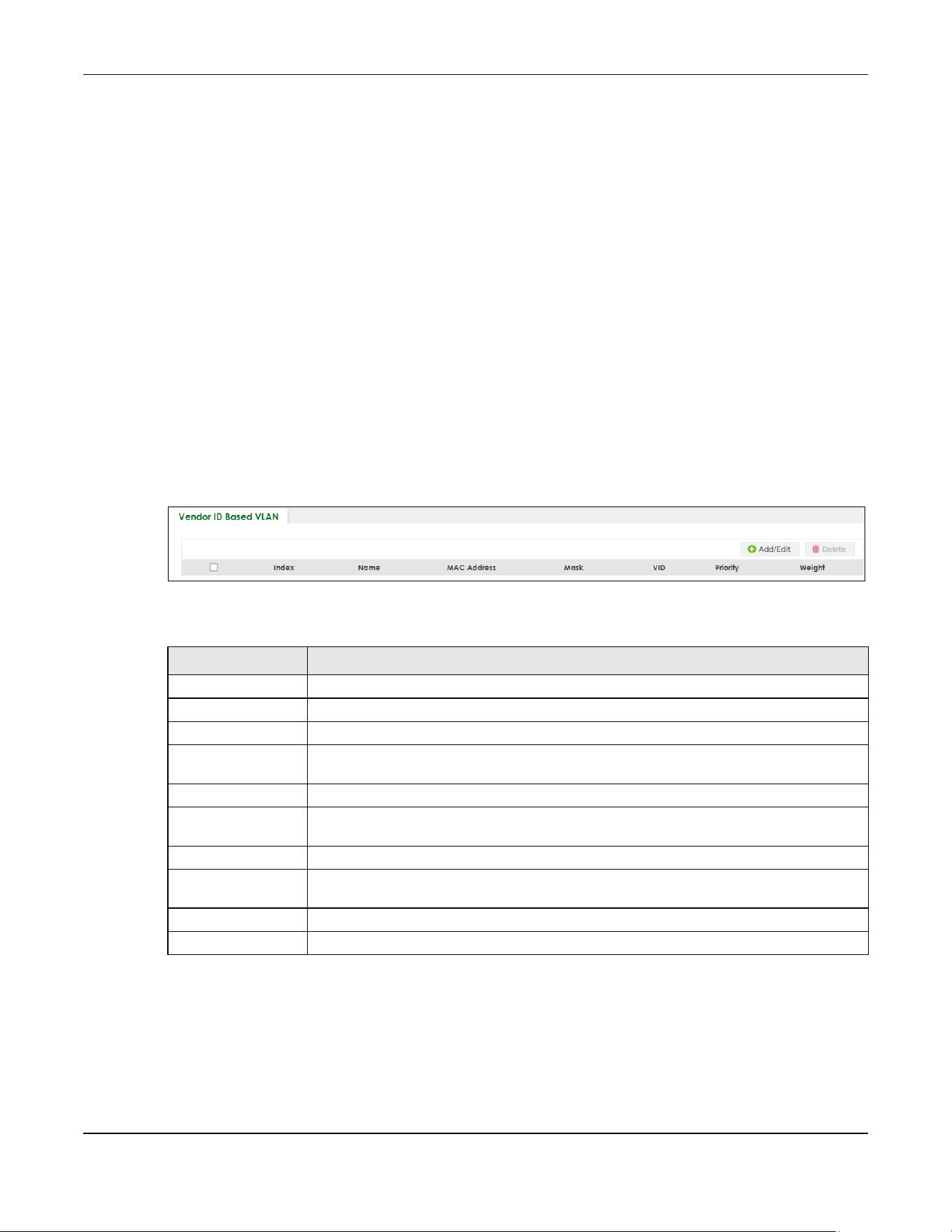
Chapter 57 VLAN
XGS2220 Series User’s Guide
437
57.13 Vendor ID Based VLAN
The Vendor ID based VLAN feature assigns incoming untagged packets to a VLAN and classifies the
traffic based on the source MAC address of the packet. When untagged packets arrive at the switch,
the source MAC address of the packet is looked up in a Vendor ID to VLAN mapping table. If an entry is
found, the corresponding VLAN ID is assigned to the packet. The assigned VLAN ID is verified against the
VLAN table. If the VLAN is valid, ingress processing on the packet continues; otherwise, the packet is
dropped.
This feature allows users to change ports without having to reconfigure the VLAN. You can assign a
802.1p priority to the vendor ID based VLAN and define a vendor ID to VLAN mapping table by entering
a specified source MAC address and mask in the vendor ID based VLAN setup screen. You can also
delete a vendor ID based VLAN entry in the same screen.
For every vendor ID based VLAN rule you set, you can specify a weight number to define the rule’s
priority level. As rules are processed one after the other, stating a priority order will let you choose which
rule has to be applied first and which second.
Click the SWITCHING > VLAN > Vendor ID Based VLAN Setup to see the following screen.
Figure 346 SWITCHING > VLAN > Vendor ID Based VLAN Setup
The following table describes the fields in the above screen.
57.13.1 Add/Edit a Vendor ID Based VLAN
Click Add/Edit, or select an entry and click Add/Edit in the SWITCHING > VLAN > Vendor ID Based VLAN
Setup to see this screen.
Table 218 SWITCHING > VLAN > Vendor ID Based VLAN Setup
LABEL DESCRIPTION
Index This field displays the index number of the vendor ID based VLAN entry.
Name This field displays the name of the vendor ID based VLAN entry.
MAC Address This field displays the source MAC address that is bind to the vendor ID based VLAN entry.
Mask This field displays the mask for the source MAC address that is bind to the vendor ID based
VLAN entry.
VLAN This field displays the VLAN ID of the vendor ID based VLAN entry.
Priority This field displays the priority level which is assigned to frames belonging to this vendor ID
based VLAN.
Weight This field displays the weight of the vendor ID based VLAN entry.
Select an entry’s check box to select a specific entry. Otherwise, select the check box in
the table heading row to select all entries.
Add/Edit Click Add/Edit to add a new entry or edit a selected one.
Delete Click Delete to remove the selected entry.

Chapter 57 VLAN
XGS2220 Series User’s Guide
438
Figure 347 SWITCHING > VLAN > Vendor ID Based VLAN Setup > Add/Edit
The following table describes the fields in the above screen.
57.14 Port-Based VLAN Setup
Port-based VLANs are VLANs where the packet forwarding decision is based on the destination MAC
address and its associated port.
Port-based VLANs require allowed outgoing ports to be defined for each port. Therefore, if you wish to
allow two subscriber ports to talk to each other, for example, between conference rooms in a hotel, you
must define the egress (an egress port is an outgoing port, that is, a port through which a data packet
leaves) for both ports.
Table 219 SWITCHING > VLAN > Vendor ID Based VLAN Setup > Add/Edit
LABEL DESCRIPTION
Name Enter a name up to 32 alphanumeric characters except [ ? ], [ | ], [ ' ], or [ " ] for the vendor
ID based VLAN entry.
MAC Address Enter a MAC address that is bind to the vendor ID-based VLAN entry. This is the source MAC
address of the data packet that is looked up when untagged packets arrive at the Switch.
Mask Enter the mask for the specified source MAC address to determine which bits a packet’s
MAC address should match.
Enter “f” for each bit of the specified MAC address that the traffic’s MAC address should
match. Enter “0” for the bits of the matched traffic’s MAC address, which can be of any
hexadecimal characters. For example, if you set the MAC address to 00:13:49:00:00:00 and
the mask to ff:ff:ff:00:00:00, a packet with a MAC address of 00:13:49:12:34:56 matches this
criteria.
VID Enter an ID (from 1 to 4094) for the VLAN that is associated with the vendor ID based VLAN
entry.
Priority Select the priority level that the Switch assigns to frames belonging to this VLAN. The higher
the numeric value you assign, the higher the priority for this vendor ID based VLAN entry.
Weight Enter a number between 0 and 255 to specify the rule’s weight. This is to decide the priority
in which the rule is applied. The higher the number, the higher the rule’s priority.
Apply Click Apply to save your changes to the Switch’s run-time memory. The Switch loses these
changes if it is turned off or loses power, so use the Save link on the top navigation panel to
save your changes to the non-volatile memory when you are done configuring.
Clear Click Clear to clear the fields to the factory defaults.
Cancel Click Cancel to not save the configuration you make and return to the last screen.
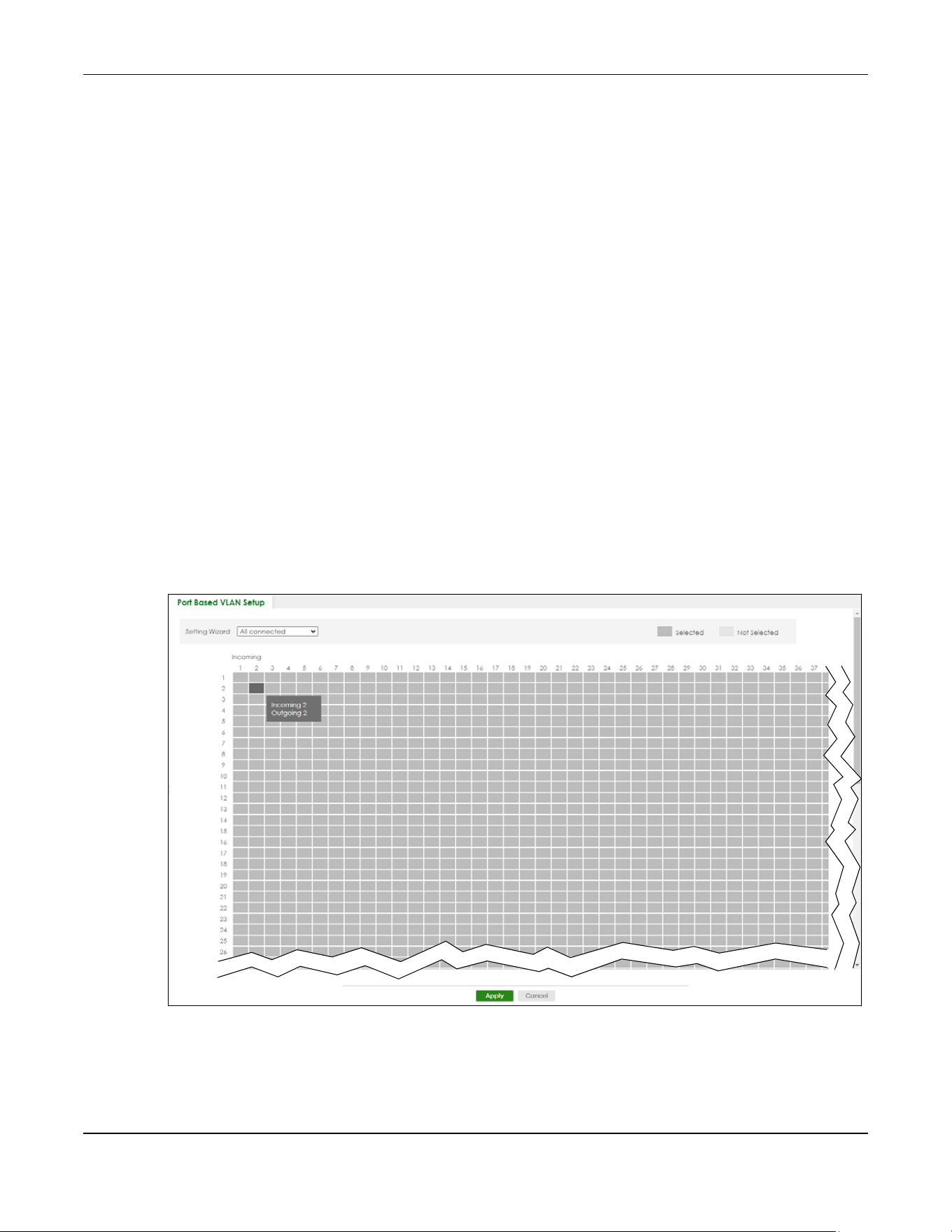
Chapter 57 VLAN
XGS2220 Series User’s Guide
439
Port-based VLANs are specific only to the Switch on which they were created.
Note: When you activate port-based VLAN, the Switch uses a default VLAN ID of 1. You
cannot change it.
Note: In screens (such as SYSTEM > IP Setup and SWITCHING > Static MAC Filtering) that
require a VID, you must enter 1 as the VID.
The port-based VLAN setup screen is shown next. The CPU management port forms a VLAN with all
Ethernet ports.
57.15 Configure a Port-Based VLAN
Select Port Based as the VLAN Type in the SYSTEM > Switch Setup screen and then click SWITCHING >
VLAN from the navigation panel to display the next screen.
Select either All Connected or Port Isolated from the drop-down list depending on your VLAN and VLAN
security requirements. If VLAN members need to communicate directly with each other, then select All
Connected. Select Port Isolated if you want to restrict users from communicating directly. Click Apply to
save your settings.
The following screen shows users on a port-based, all-connected VLAN configuration.
Figure 348 SWITCHING > VLAN > Port Based VLAN Setup (All Connected)
The following screen shows users on a port-based, port-isolated VLAN configuration.

Chapter 57 VLAN
XGS2220 Series User’s Guide
440
Figure 349 SWITCHING > VLAN: Port Based VLAN Setup (Port Isolation)
The following table describes the labels in this screen.
Table 220 SWITCHING > VLAN > Port Based VLAN Setup
LABEL DESCRIPTION
Setting Wizard Choose Current configuration to display the Switch’s current port-based VLAN configuration.
Choose All connected or Port isolation wizard to quickly set up a port-based VLAN according to
the below descriptions.
All connected means all ports can communicate with each other, that is, there are no virtual
LANs. All incoming and outgoing ports are selected. This option is the most flexible but also the
least secure.
Port isolation means that each port can only communicate with the CPU management port and
cannot communicate with each other. All incoming ports are selected while only the CPU
outgoing port is selected. This option is the most limiting but also the most secure.
After selecting the setting wizard, you can customize the port settings. Click on the ports to add or
delete incoming or outgoing ports. The configuration will be saved only after you click Apply at
the bottom of the screen.
Incoming These are the ingress ports; an ingress port is an incoming port, that is, a port through which a data
packet enters. If you wish to allow two subscriber ports to talk to each other, you must define the
ingress port for both ports. The numbers in the top row denote the incoming port for the
corresponding port listed on the left (its outgoing port). CPU refers to the Switch management
port. By default it forms a VLAN with all Ethernet ports. If it does not form a VLAN with a particular
port then the Switch cannot be managed from that port.
Outgoing These are the egress ports; an egress port is an outgoing port, that is, a port through which a data
packet leaves. If you wish to allow two subscriber ports to talk to each other, you must define the
egress port for both ports. CPU refers to the Switch management port. By default it forms a VLAN
with all Ethernet ports. If it does not form a VLAN with a particular port then the Switch cannot be
managed from that port.

Chapter 57 VLAN
XGS2220 Series User’s Guide
441
Apply Click Apply to save your changes to the Switch’s run-time memory. The Switch loses these
changes if it is turned off or loses power, so use the Save link on the top navigation panel to save
your changes to the non-volatile memory when you are done configuring.
Cancel Click Cancel to begin configuring this screen afresh.
Table 220 SWITCHING > VLAN > Port Based VLAN Setup (continued)
LABEL DESCRIPTION
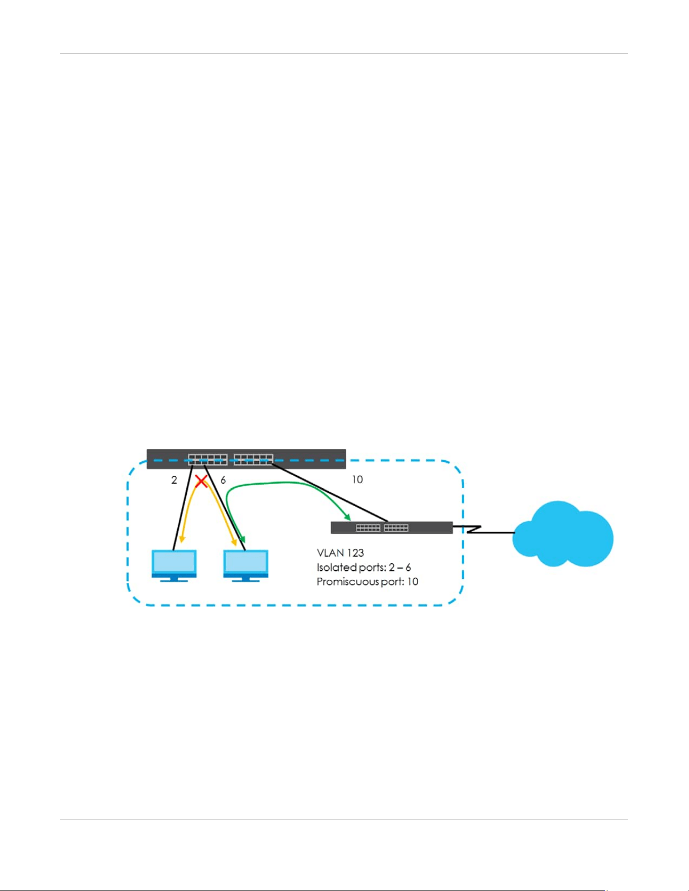
Chapter 58 VLAN Isolation
XGS2220 Series User’s Guide
442
CHAPTER 58
VLAN Isolation
This chapter shows you how to configure the Switch to prevent communications between ports in a
VLAN.
58.1 VLAN Isolation Overview
VLAN Isolation allows you to do port isolation within a VLAN in a simple way. You specify which ports in a
VLAN is not isolated by adding it to the promiscuous port list. The Switch automatically adds other ports
in this VLAN to the isolated port list and blocks traffic between the isolated ports. A promiscuous port can
communicate with any port in the same VLAN. An isolated port can communicate with the promiscuous
ports only.
Note: You can have up to one VLAN Isolation rule for each VLAN.
Figure 350 VLAN Isolation Example
Note: Make sure you keep at least one port in the promiscuous port list for a VLAN with VLAN
Isolation enabled. Otherwise, this VLAN is blocked from the whole network.
58.2 Configuring VLAN Isolation
Click SWITCHING > VLAN Isolation in the navigation panel to display the screen as shown.

Chapter 58 VLAN Isolation
XGS2220 Series User’s Guide
443
Figure 351 SWITCHING > VLAN Isolation
The following table describes the labels in this screen.
58.2.1 Add/Edit a VLAN Isolation Rule
Click Add/Edit, or select an entry and click Add/Edit in the SWITCHING > VLAN Isolation screen to display
this screen.
Figure 352 SWITCHING > VLAN Isolation > Add/Edit
The following table describes the labels in this screen.
Table 221 SWITCHING > VLAN Isolation
LABEL DESCRIPTION
Index This is the index number of the rule.
Active This shows whether this rule is activated or not.
Name This is the descriptive name for this rule.
VLAN ID This is the VLAN to which this rule is applied.
Promiscuous Ports This shows the ports that can communicate with any ports in the same VLAN.
Select an entry’s check box to select a specific entry. Otherwise, select the check box in the
table heading row to select all entries.
Add/Edit Click Add/Edit to add a new entry or edit a selected one.
Delete Click Delete to remove the selected entries.
Table 222 SWITCHING > VLAN Isolation > Add/Edit
LABEL DESCRIPTION
Active Enable the switch button to enable VLAN Isolation in a VLAN.
Name Enter a descriptive name (up to 32 printable ASCII characters except [ ? ], [ | ], [ ' ], [ " ] or [ ,
]) for identification purposes.
VLAN ID Enter a VLAN ID from 1 to 4094. This is the VLAN to which this rule applies.
Promiscuous Ports Enter the number of the ports that can communicate with any ports in the same VLAN.
Other ports belonging to this VLAN will be added to the isolation list and can only send and
receive traffic from the ports you specify here.

Chapter 58 VLAN Isolation
XGS2220 Series User’s Guide
444
Apply Click Apply to save your changes to the Switch’s run-time memory. The Switch loses these
changes if it is turned off or loses power, so use the Save link on the top navigation panel to
save your changes to the non-volatile memory when you are done configuring.
Clear Click Clear to clear the fields to the factory defaults.
Cancel Click Cancel to not save the configuration you make and return to the last screen.
Table 222 SWITCHING > VLAN Isolation > Add/Edit (continued)
LABEL DESCRIPTION

Chapter 59 VLAN Mapping
XGS2220 Series User’s Guide
445
CHAPTER 59
VLAN Mapping
This chapter shows you how to configure VLAN mapping on the Switch.
59.1 VLAN Mapping Overview
With VLAN mapping enabled, the Switch can map the VLAN ID and priority level of packets received
from a private network to those used in the service provider’s network.
The Switch checks incoming traffic from the switch ports (non-management ports) against the VLAN
mapping table first, the MAC learning table and then the VLAN table before forwarding them through
the Gigabit uplink port. When VLAN mapping is enabled, the Switch discards the tagged packets that
do not match an entry in the VLAN mapping table. If the incoming packets are untagged, the Switch
adds a PVID based on the VLAN setting.
Note: You cannot enable VLAN mapping and VLAN stacking at the same time.
59.1.1 VLAN Mapping Example
In the following example figure, packets that carry VLAN ID 12 and are received on port 3 match a pre-
configured VLAN mapping rule. The Switch translates the VLAN ID from 12 into 123 before forwarding the
packets. Any packets carrying a VLAN tag other than 12 (such as 10) and received on port 3 will be
dropped.
Figure 353 VLAN Mapping Example
59.1.2 What You Can Do
• Use the VLAN Mapping screen (Section 59.2 on page 446) to enable VLAN mapping on the Switch and

Chapter 59 VLAN Mapping
XGS2220 Series User’s Guide
446
ports.
• Use the VLAN Mapping Setup screen (Section 59.3 on page 447) to enable and edit the VLAN
mapping rules.
59.2 Enable VLAN Mapping
Click SWITCHING > VLAN Mapping in the navigation panel to display the screen as shown.
Figure 354 SWITCHING > VLAN Mapping > VLAN Mapping (Standalone Mode)

Chapter 59 VLAN Mapping
XGS2220 Series User’s Guide
447
Figure 355 SWITCHING > VLAN Mapping > VLAN Mapping (Stacking Mode)
The following table describes the labels in this screen.
59.3 VLAN Mapping Setup
Click the SWITCHING > VLAN Mapping > VLAN Mapping Setup to display the screen as shown. Use this
screen to view and configure the VLAN mapping rules.
Table 223 SWITCHING > VLAN Mapping > VLAN Mapping
LABEL DESCRIPTION
Active Enable the switch button to enable VLAN mapping on the Switch.
SLOT This field appears only in Stacking mode. Click the drop-down list to choose the slot number of
the Switch in a stack.
Port This field displays the port number. In Stacking mode, the first number represents the slot ID and
the second is the port number. Please note that the default stacking ports (the last four ports of
your Switch) cannot be configured. They are reserved for stacking only.
* Settings in this row apply to all ports.
Use this row only if you want to make some settings the same for all ports. Use this row first to set
the common settings and then make adjustments on a port-by-port basis.
Note: Changes in this row are copied to all the ports as soon as you make them.
Active Select this check box to enable the VLAN mapping feature on this port. Clear this check box to
disable the VLAN mapping feature.
Apply Click Apply to save your changes to the Switch’s run-time memory. The Switch loses these
changes if it is turned off or loses power, so use the Save link on the top navigation panel to save
your changes to the non-volatile memory when you are done configuring.
Cancel Click Cancel to begin configuring this screen afresh.

Chapter 59 VLAN Mapping
XGS2220 Series User’s Guide
448
Figure 356 SWITCHING > VLAN Mapping > VLAN Mapping Setup
The following table describes the labels in this screen.
59.3.1 Add/Edit VLAN Mapping
Click Add/Edit, or select an entry and click Add/Edit in the SWITCHING > VLAN Mapping > VLAN
Mapping Setup to display this screen. Use this screen to enable and edit the VLAN mapping rules.
Figure 357 SWITCHING > VLAN Mapping > VLAN Mapping Setup > Add/Edit (Standalone Mode)
Table 224 SWITCHING > VLAN Mapping > VLAN Mapping Setup
LABEL DESCRIPTION
Index This is the number of the VLAN mapping entry in the table.
Active This shows whether this entry is activated or not.
Name This is the descriptive name for this rule.
Port This is the port number to which this rule is applied.
In Stacking mode, the first number represents the slot ID and the second is the port number.
VID This is the customer VLAN ID in the incoming packets.
Translated VID This is the VLAN ID that replaces the customer VLAN ID in the tagged packets.
Priority This is the priority level that replaces the customer priority level in the tagged packets.
Select an entry’s check box to select a specific entry. Otherwise, select the check box in the
table heading row to select all entries.
Add/Edit Click Add/Edit to add a new entry or edit a selected one.
Delete Click Delete to remove the selected entries.

Chapter 59 VLAN Mapping
XGS2220 Series User’s Guide
449
Figure 358 SWITCHING > VLAN Mapping > VLAN Mapping Setup > Add/Edit (Stacking Mode)
The following table describes the labels in this screen.
Table 225 SWITCHING > VLAN Mapping > VLAN Mapping Setup > Add/Edit
LABEL DESCRIPTION
Active Enable the switch button to activate this rule.
Name Enter a descriptive name (up to 32 printable ASCII characters except [ ? ], [ | ], [ ' ], [ " ] or [ , ])
for identification purposes.
Port Type a port to be included in this rule. In Stacking mode, the first field is the slot ID and the
second field is the port number.
VID Enter a VLAN ID from 1 to 4094. This is the VLAN tag carried in the packets and will be translated
into the VID you specified in the Translated VID field.
Translated VID Enter a VLAN ID (from 1 to 4094) into which the customer VID carried in the packets will be
translated.
Priority Select a priority level (from 0 to 7). This is the priority level that replaces the customer priority
level in the tagged packets or adds to the untagged packets.
Apply Click Apply to save your changes to the Switch’s run-time memory. The Switch loses these
changes if it is turned off or loses power, so use the Save link on the top navigation panel to
save your changes to the non-volatile memory when you are done configuring.
Clear Click Clear to clear the fields to the factory defaults.
Cancel Click Cancel to not save the configuration you make and return to the last screen.

Chapter 60 VLAN Stacking
XGS2220 Series User’s Guide
450
CHAPTER 60
VLAN Stacking
This chapter shows you how to configure VLAN stacking on your Switch. See the chapter on VLANs for
more background information on Virtual LANs (VLANs).
60.1 VLAN Stacking Overview
A service provider can use VLAN stacking to allow it to distinguish multiple customers VLANs, even those
with the same (customer-assigned) VLAN ID, within its network.
Use VLAN stacking to add an outer VLAN tag to the inner IEEE 802.1Q tagged frames that enter the
network. By tagging the tagged frames (“double-tagged” frames), the service provider can manage
up to 4094 VLAN groups with each group containing up to 4094 customer VLANs. This allows a service
provider to provide different service, based on specific VLANs, for many different customers.
A service provider’s customers may require a range of VLANs to handle multiple applications. A service
provider’s customers can assign their own inner VLAN tags on ports for these applications. The service
provider can assign an outer VLAN tag for each customer. Therefore, there is no VLAN tag overlap
among customers, so traffic from different customers is kept separate.
60.1.1 VLAN Stacking Example
In the following example figure, both A and B are Service Provider’s Network (SPN) customers with VPN
tunnels between their head offices and branch offices respectively. Both have an identical VLAN tag for
their VLAN group. The service provider can separate these two VLANs within its network by adding tag
37 to distinguish customer A and tag 48 to distinguish customer B at edge device 1 and then stripping
those tags at edge device 2 as the data frames leave the network.
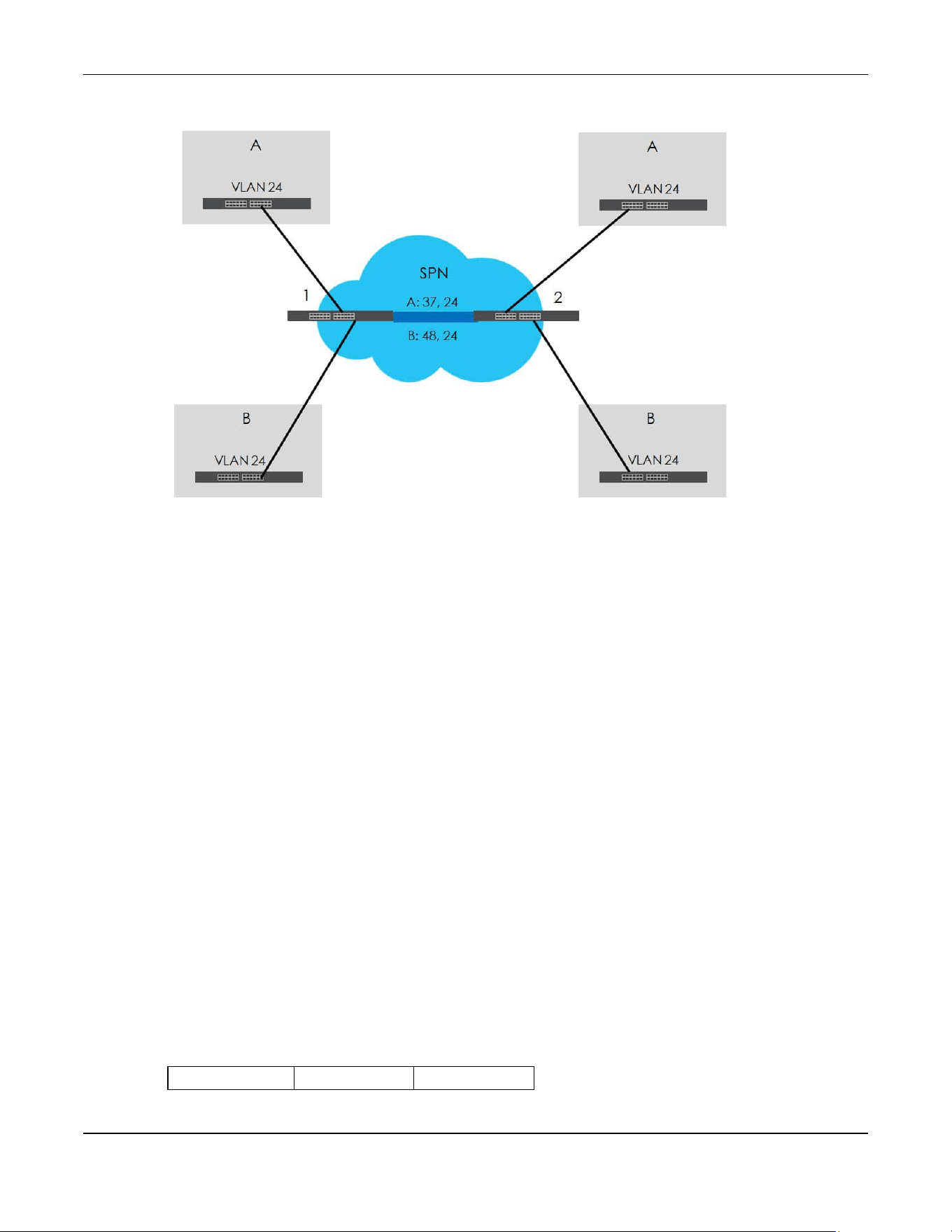
Chapter 60 VLAN Stacking
XGS2220 Series User’s Guide
451
Figure 359 VLAN Stacking Example
60.2 VLAN Stacking Port Roles
Each port can have three VLAN stacking “roles”, Normal, Access, and Tunnel (the latter is for Gigabit
ports only).
•Select Normal for “regular” (non-VLAN stacking) IEEE 802.1Q frame switching.
•Select Access for ingress ports on the service provider's edge devices (1 and 2 in the VLAN stacking
example figure). The incoming frame is treated as "untagged", so a second VLAN tag (outer VLAN
tag) can be added.
Note: Static VLAN Tx Tagging MUST be disabled on a port where you choose Normal or
Access.
•Select Tunnel (available for Gigabit ports only) for egress ports at the edge of the service provider's
network. All VLANs belonging to a customer can be aggregated into a single service provider's VLAN
(using the outer VLAN tag defined by the Service Provider’s (SP) VLAN ID (VID)).
Note: Static VLAN Tx Tagging MUST be enabled on a port where you choose Tunnel.
60.3 VLAN Tag Format
A VLAN tag (service provider VLAN stacking or customer IEEE 802.1Q) consists of the following three
fields.
Table 226 VLAN Tag Format
Type Priority VID

Chapter 60 VLAN Stacking
XGS2220 Series User’s Guide
452
Type is a standard Ethernet type code identifying the frame and indicates that whether the frame
carries IEEE 802.1Q tag information. SP TPID (Service Provider Tag Protocol Identifier) is the service
provider VLAN stacking tag type. Many vendors use 0x8100 or 0x9100.
TPID (Tag Protocol Identifier) is the customer IEEE 802.1Q tag.
• If the VLAN stacking port role is Access port, then the Switch adds the SP TPID tag to all incoming
frames on the service provider's edge devices (1 and 2 in the VLAN stacking example figure).
• If the VLAN stacking port role is Tunnel port, then the Switch only adds the SP TPID tag to all incoming
frames on the service provider's edge devices (1 and 2 in the VLAN stacking example figure) that
have an SP TPID different to the one configured on the Switch. (If an incoming frame’s SP TPID is the
same as the one configured on the Switch, then the Switch will not add the tag.)
Priority refers to the IEEE 802.1p standard that allows the service provider to prioritize traffic based on the
class of service (CoS) the customer has paid for.
• On the Switch, configure priority level of the inner IEEE 802.1Q tag in the PORT > Port Setup screen.
• "0" is the lowest priority level and "7" is the highest.
VID is the VLAN ID. SPVID is the VID for the second (service provider’s) VLAN tag.
60.3.1 Frame Format
The frame format for an untagged Ethernet frame, a single-tagged 802.1Q frame (customer) and a
“double-tagged” 802.1Q frame (service provider) is shown next.
Configure the fields as highlighted in the Switch SWITCHING > VLAN Stacking screens.
60.4 Configuring VLAN Stacking
Click SWITCHING > VLAN Stacking to display the screen as shown.
Table 227 Single and Double Tagged 802.1Q Frame Format
DA SA Len/Etype Data FCS Untagged
Ethernet frame
DA SA TPID Priority VID Len/Etype Data FCS
IEEE 802.1Q
customer
tagged frame
DA SA SPTPID Priority VID TPID Priority VID Len/Etype Data FCS
Double-tagged
frame
Table 228 802.1Q Frame
DA Destination Address Priority 802.1p Priority
SA Source Address Len/Etype Length and type of Ethernet frame
(SP)TPID (Service Provider) Tag Protocol IDentifier Data Frame data
VID VLAN ID FCS Frame Check Sequence
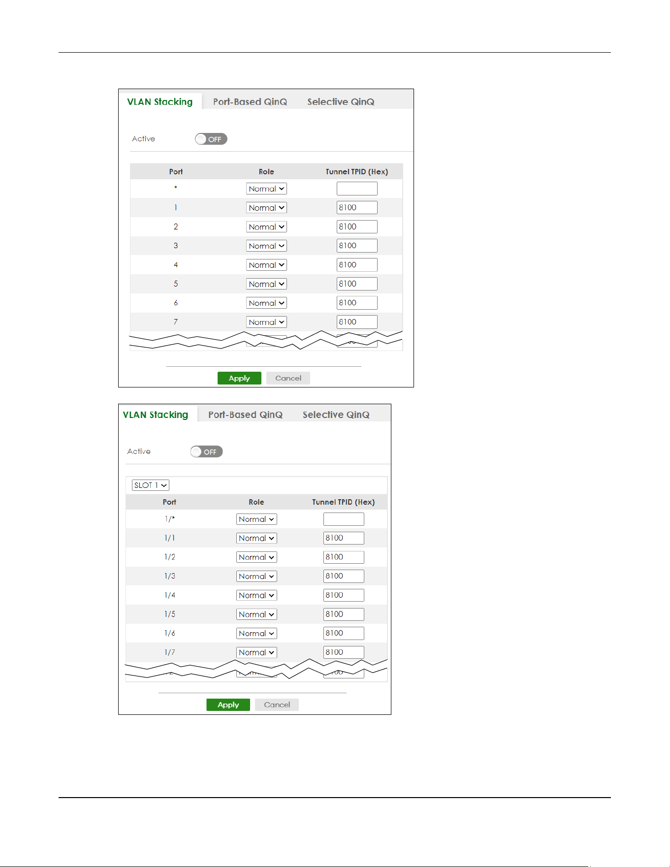
Chapter 60 VLAN Stacking
XGS2220 Series User’s Guide
453
Figure 360 SWITCHING > VLAN Stacking > VLAN Stacking (Standalone Mode)
Figure 361 SWITCHING > VLAN Stacking > VLAN Stacking (Stacking Mode)

Chapter 60 VLAN Stacking
XGS2220 Series User’s Guide
454
The following table describes the labels in this screen.
60.5 Port-Based Q-in-Q
Port-based Q-in-Q lets the Switch treat all frames received on the same port as the same VLAN flows
and add the same outer VLAN tag to them, even if they have different customer VLAN IDs.
Click SWITCHING > VLAN Stacking > Port-Based QinQ to display the screen as shown.
Table 229 SWITCHING > VLAN Stacking > VLAN Stacking
LABEL DESCRIPTION
Active Enable the switch button to enable VLAN stacking on the Switch.
SLOT This field appears only in Stacking mode. Click the drop-down list to choose the slot number of the
Switch in a stack.
Port This field displays the port number. In Stacking mode, the first number represents the slot ID and the
second is the port number. Please note that the default stacking ports (the last four ports of your
Switch) cannot be configured. They are reserved for stacking only.
* Settings in this row apply to all ports.
Use this row only if you want to make some settings the same for all ports. Use this row first to set the
common settings and then make adjustments on a port-by-port basis.
Note: Changes in this row are copied to all the ports as soon as you make them.
Role Select Normal to have the Switch ignore frames received (or transmitted) on this port with VLAN
stacking tags. Anything you configure in SPVID and Priority of the Port-based QinQ or the Selective
QinQ screen are ignored.
Select Access to have the Switch add the SP TPID tag to all incoming frames received on this port.
Select Access for ingress ports at the edge of the service provider's network.
Select Tunnel (available for Gigabit ports only) for egress ports at the edge of the service provider's
network. Select Tunnel to have the Switch add the Tunnel TPID (HEX) tag to all outgoing frames
sent on this port.
In order to support VLAN stacking on a port, the port must be able to allow frames of 1526 Bytes
(1522 Bytes + 4 Bytes for the second tag) to pass through it.
Tunnel TPID
(HEX)
TPID is a standard Ethernet type code identifying the frame and indicates whether the frame
carries IEEE 802.1Q tag information. Enter a four-digit hexadecimal number from 0000 to FFFF that
the Switch adds in the outer VLAN tag of the frames sent on the tunnel ports. The Switch also uses
this to check if the received frames are double-tagged.
The value of this field is 0x8100 as defined in IEEE 802.1Q. It is used to identify the customer tag of an
incoming frame. If the Switch needs to communicate with other vendors’ devices, they should use
the same TPID.
Note: You can define up to four different tunnel TPIDs (including 8100) in this screen at a
time.
Apply Click Apply to save your changes to the Switch’s run-time memory. The Switch loses these changes
if it is turned off or loses power, so use the Save link on the top navigation panel to save your
changes to the non-volatile memory when you are done configuring.
Cancel Click Cancel to begin configuring this screen afresh.
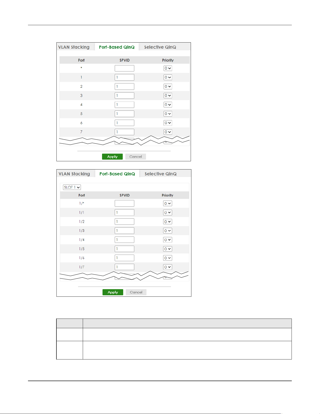
Chapter 60 VLAN Stacking
XGS2220 Series User’s Guide
455
Figure 362 SWITCHING > VLAN Stacking > Port-Based QinQ (Standalone Mode)
Figure 363 SWITCHING > VLAN Stacking > Port-Based QinQ (Stacking Mode)
The following table describes the labels in this screen.
Table 230 SWITCHING > VLAN Stacking > Port-Based QinQ
LABEL DESCRIPTION
SLOT This field appears only in Stacking mode. Click the drop-down list to choose the slot number of the
Switch in a stack.
Port This field displays the port number. In Stacking mode, the first number represents the slot ID and the
second is the port number. Please note that the default stacking ports (the last four ports of your
Switch) cannot be configured. They are reserved for stacking only.
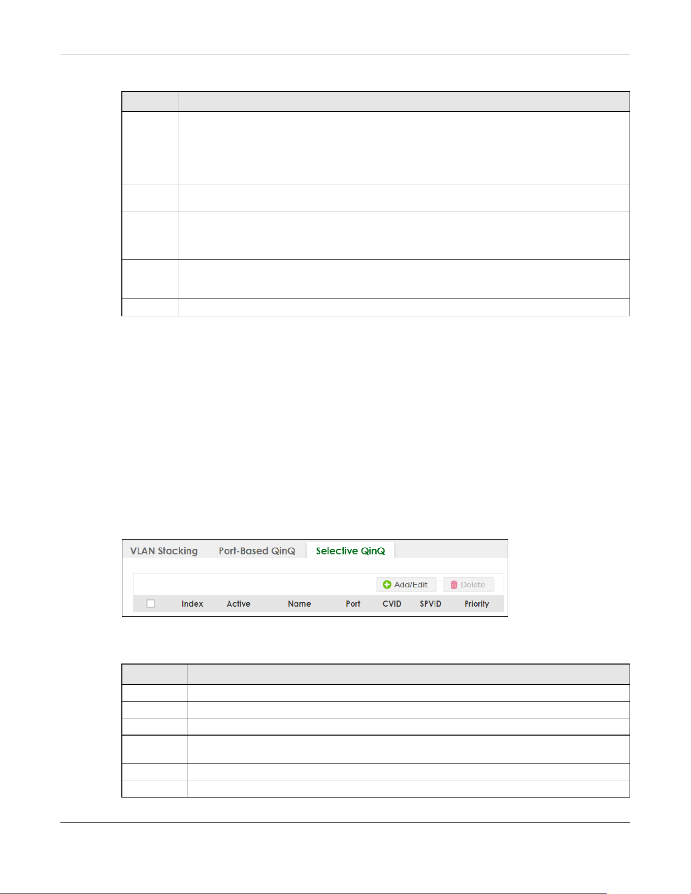
Chapter 60 VLAN Stacking
XGS2220 Series User’s Guide
456
60.6 Selective Q-in-Q
Selective Q-in-Q is VLAN-based. It allows the Switch to add different outer VLAN tags to the incoming
frames received on one port according to their inner VLAN tags.
Note: Selective Q-in-Q rules are only applied to single-tagged frames received on the access
ports. If the incoming frames are untagged or single-tagged but received on a tunnel
port or cannot match any selective Q-in-Q rules, the Switch applies the port-based Q-
in-Q rules to them.
Click SWITCHING > VLAN Stacking > Selective QinQ to display the screen as shown.
Figure 364 SWITCHING > VLAN Stacking > Selective QinQ
The following table describes the labels in this screen.
* Settings in this row apply to all ports.
Use this row only if you want to make some settings the same for all ports. Use this row first to set the
common settings and then make adjustments on a port-by-port basis.
Note: Changes in this row are copied to all the ports as soon as you make them.
SPVID SPVID is the service provider’s VLAN ID (the outer VLAN tag). Enter the service provider ID (from 1 to
4094) for frames received on this port.
Priority Select a priority level (from 0 to 7). This is the service provider’s priority level that adds to the frames
received on this port.
"0" is the lowest priority level and "7" is the highest.
Apply Click Apply to save your changes to the Switch’s run-time memory. The Switch loses these changes if it
is turned off or loses power, so use the Save link on the top navigation panel to save your changes to
the non-volatile memory when you are done configuring.
Cancel Click Cancel to begin configuring this screen afresh.
Table 230 SWITCHING > VLAN Stacking > Port-Based QinQ (continued)
LABEL DESCRIPTION
Table 231 SWITCHING > VLAN Stacking > Selective QinQ
LABEL DESCRIPTION
Index This is the number of the selective VLAN stacking rule.
Active This shows whether this rule is activated or not.
Name This is the descriptive name for this rule.
Port This is the port number to which this rule is applied. In Stacking mode, the first number represents the
slot and the second the port number.
CVID This is the customer VLAN ID in the incoming packets.
SPVID This is the service provider’s VLAN ID that adds to the packets from the subscribers.

Chapter 60 VLAN Stacking
XGS2220 Series User’s Guide
457
60.6.1 Add/Edit Selective Q-in-Q
Click Add/Edit, or select an entry and click Add/Edit in the SWITCHING > VLAN Stacking > Selective QinQ
screen to display this screen.
Figure 365 SWITCHING > VLAN Stacking > Selective QinQ > Add/Edit (Standalone Mode)
Figure 366 SWITCHING > VLAN Stacking > Selective QinQ > Add/Edit (Stacking Mode)
The following table describes the labels in this screen.
Priority This is the service provider’s priority level in the packets.
Select an entry’s check box to select a specific entry. Otherwise, select the check box in the table
heading row to select all entries.
Add/Edit Click Add/Edit to add a new entry or edit a selected one.
Delete Click Delete to remove the selected entries.
Table 231 SWITCHING > VLAN Stacking > Selective QinQ (continued)
LABEL DESCRIPTION
Table 232 SWITCHING > VLAN Stacking > Selective QinQ > Add/Edit
LABEL DESCRIPTION
Active Enable the switch button to activate this rule.
Name Enter a descriptive name (up to 32 printable ASCII characters except [ ? ], [ | ], [ ' ], [ " ] or [ , ]) for
identification purposes.
Port The port number identifies the port you are configuring. In Stacking mode, the first field is the slot ID
and the second field is the port number.
CVID Enter a customer VLAN ID (the inner VLAN tag) from 1 to 4094. This is the VLAN tag carried in the
packets from the subscribers.
Chapter 60 VLAN Stacking
XGS2220 Series User’s Guide
458
SPVID SPVID is the service provider’s VLAN ID (the outer VLAN tag). Enter the service provider ID (from 1 to
4094) for frames received on this port.
Priority Select a priority level (from 0 to 7). This is the service provider’s priority level that adds to the frames
received on this port.
"0" is the lowest priority level and "7" is the highest.
Apply Click Apply to save your changes to the Switch’s run-time memory. The Switch loses these changes
if it is turned off or loses power, so use the Save link on the top navigation panel to save your
changes to the non-volatile memory when you are done configuring.
Clear Click Clear to clear the fields to the factory defaults.
Cancel Click Cancel to not save the configuration you make and return to the last screen.
Table 232 SWITCHING > VLAN Stacking > Selective QinQ > Add/Edit (continued)
LABEL DESCRIPTION


Chapter 62 ARP Setup
XGS2220 Series User’s Guide
460
CHAPTER 62
ARP Setup
62.1 ARP Overview
Address Resolution Protocol (ARP) is a protocol for mapping an Internet Protocol address (IP address) to
a physical machine address, also known as a Media Access Control or MAC address, on the local area
network.
An IP (version 4) address is 32 bits long. In an Ethernet LAN, MAC addresses are 48 bits long. The ARP
table maintains an association between each MAC address and its corresponding IP address.
62.1.1 What You Can Do
Use the ARP Learning screen (Section 62.2 on page 462) to configure ARP learning mode on a per-port
basis.
Use the Static ARP screen (Section 62.3 on page 464) to create static ARP entries that will display in the
MONITOR > ARP Table screen and will not age out.
62.1.2 What You Need to Know
Read on for concepts on ARP that can help you configure the screen in this chapter.
62.1.2.1 How ARP Works
When an incoming packet destined for a host device on a local area network arrives at the Switch, the
Switch looks in the ARP Table and if it finds the address, it sends it to the device.
If no entry is found for the IP address, ARP broadcasts the request to all the devices on the LAN. The
Switch fills in its own MAC and IP address in the sender address fields, and puts the known IP address of
the target in the target IP address field. In addition, the Switch puts all ones in the target MAC field
(FF.FF.FF.FF.FF.FF is the Ethernet broadcast address). The replying device (which is either the IP address of
the device being sought or the router that knows the way) replaces the broadcast address with the
target's MAC address, swaps the sender and target pairs, and unicasts the answer directly back to the
requesting machine. ARP updates the ARP Table for future reference and then sends the packet to the
MAC address that replied.
62.1.2.2 ARP Learning Mode
The Switch supports three ARP learning modes: ARP-Reply, Gratuitous-ARP, and ARP-Request.
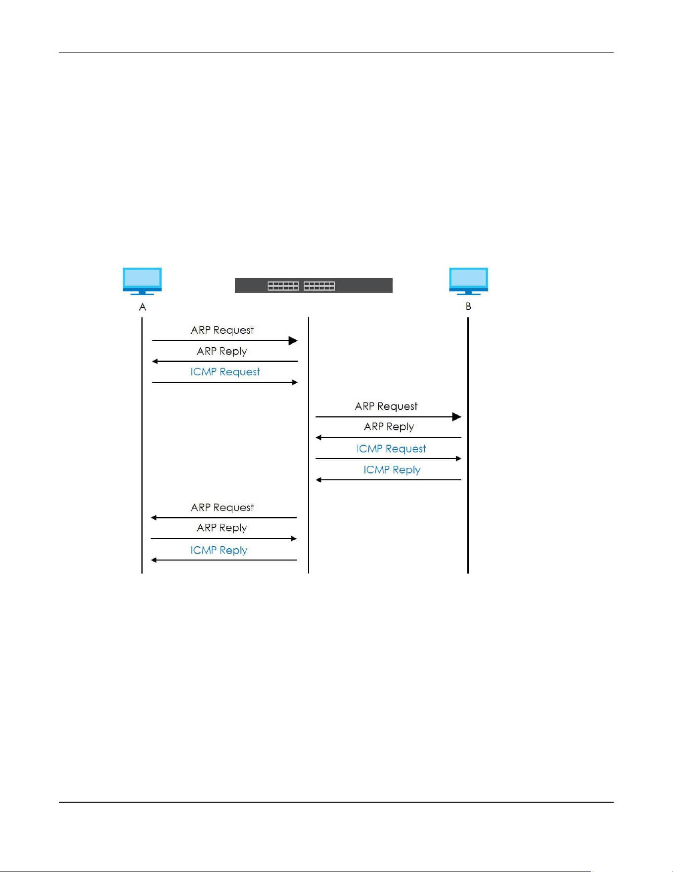
Chapter 62 ARP Setup
XGS2220 Series User’s Guide
461
ARP-Reply
The Switch in ARP-Reply learning mode updates the ARP table only with the ARP replies to the ARP
requests sent by the Switch. This can help prevent ARP spoofing.
In the following example, the Switch does not have IP address and MAC address mapping information
for hosts A and B in its ARP table, and host A wants to ping host B. Host A sends an ARP request to the
Switch and then sends an ICMP request after getting the ARP reply from the Switch. The Switch finds no
matched entry for host B in the ARP table and broadcasts the ARP request to all the devices on the LAN.
When the Switch receives the ARP reply from host B, it updates its ARP table and also forwards host A’s
ICMP request to host B. After the Switch gets the ICMP reply from host B, it sends out an ARP request to
get host A’s MAC address and updates the ARP table with host A’s ARP reply. The Switch then can
forward host B’s ICMP reply to host A.
Gratuitous-ARP
A gratuitous ARP is an ARP request in which both the source and destination IP address fields are set to
the IP address of the device that sends this request and the destination MAC address field is set to the
broadcast address. There will be no reply to a gratuitous ARP request.
A device may send a gratuitous ARP packet to detect IP collisions. If a device restarts or its MAC address
is changed, it can also use gratuitous ARP to inform other devices in the same network to update their
ARP table with the new mapping information.
In Gratuitous-ARP learning mode, the Switch updates its ARP table with either an ARP reply or a
gratuitous ARP request.

Chapter 62 ARP Setup
XGS2220 Series User’s Guide
462
ARP-Request
When the Switch is in ARP-Request learning mode, it updates the ARP table with both ARP replies,
gratuitous ARP requests and ARP requests.
Therefore in the following example, the Switch can learn host A’s MAC address from the ARP request
sent by host A. The Switch then forwards host B’s ICMP reply to host A right after getting host B’s MAC
address and ICMP reply.
62.2 ARP Learning
Use this screen to configure each port’s ARP learning mode. Click NETWORKING > ARP Setup > ARP
Learning in the navigation panel to display the screen as shown next.
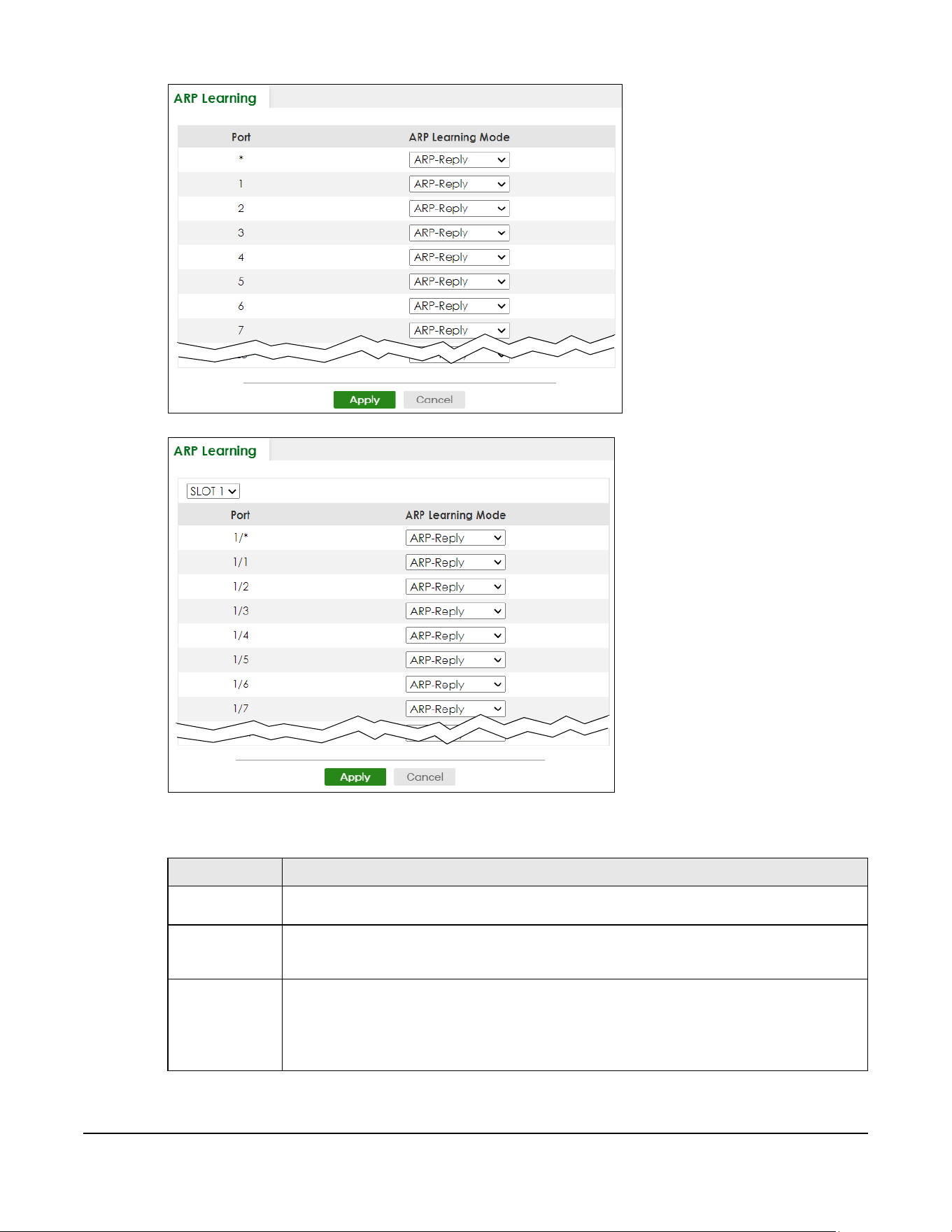
XGS2220 Series User’s Guide
463
Figure 367 NETWORKING > ARP Setup > ARP Learning (Standalone Mode)
Figure 368 NETWORKING > ARP Setup > ARP Learning (Stacking Mode)
The following table describes the labels in this screen.
Table 233 NETWORKING > ARP Setup > ARP Learning
LABEL DESCRIPTION
SLOT This field appears only in Stacking mode. Click the drop-down list to choose the slot number of
the Switch in a stack.
Port This field displays the port number. In Stacking mode, the first number represents the slot ID and
the second is the port number. Please note that the default stacking ports (the last four ports of
your Switch) cannot be configured. They are reserved for stacking only.
* Settings in this row apply to all ports.
Use this row only if you want to make some settings the same for all ports. Use this row first to set
the common settings and then make adjustments on a port-by-port basis.
Changes in this row are copied to all the ports as soon as you make them.

Chapter 62 ARP Setup
XGS2220 Series User’s Guide
464
62.3 Static ARP
Use this screen to view and configure static ARP entries that will display in the MONITOR > ARP Table
screen and will not age out. Click NETWORKING > ARP Setup > Static ARP to display the screen as shown.
Figure 369 NETWORKING > ARP Setup > Static ARP
The following table describes the related labels in this screen.
ARP Learning
Mode
Select the ARP learning mode the Switch uses on the port.
Select ARP-Reply to have the Switch update the ARP table only with the ARP replies to the ARP
requests sent by the Switch.
Select Gratuitous-ARP to have the Switch update its ARP table with either an ARP reply or a
gratuitous ARP request.
Select ARP-Request to have the Switch update the ARP table with both ARP replies, gratuitous
ARP requests and ARP requests.
Apply Click Apply to save your changes to the Switch’s run-time memory. The Switch loses these
changes if it is turned off or loses power, so use the Save link on the top navigation panel to save
your changes to the non-volatile memory when you are done configuring.
Cancel Click Cancel to begin configuring this screen afresh.
Table 233 NETWORKING > ARP Setup > ARP Learning (continued)
LABEL DESCRIPTION
Table 234 NETWORKING > ARP Setup > Static ARP
LABEL DESCRIPTION
Index This field displays the index number of an entry.
Active This field displays whether the entry is activated.
Name This field displays the descriptive name for this entry. This is for identification purposes only.
IP Address This is the IP address of a device connected to a Switch port with the corresponding MAC
address below.
MAC Address This is the MAC address of the device with the corresponding IP address above.
VID This field displays the VLAN to which the device belongs.
Port This field displays the port to which the device connects.
Select an entry’s check box to select a specific entry. Otherwise, select the check box in the
table heading row to select all entries.
Add/Edit Click Add/Edit to add a new entry or edit a selected one.
Delete Click Delete to remove the selected entries.

Chapter 62 ARP Setup
XGS2220 Series User’s Guide
465
62.3.1 Add/Edit Static ARP
Use this screen to add/edit static ARP entries. Click Add/Edit, or select an entry and click Add/Edit in the
NETWORKING > ARP Setup > Static ARP to display this screen.
Figure 370 NETWORKING > ARP Setup > Static ARP > Add/Edit (Standalone Mode)
Figure 371 NETWORKING > ARP Setup > Static ARP > Add/Edit (Stacking Mode)
The following table describes the related labels in this screen.
Table 235 NETWORKING > ARP Setup > Static ARP > Add/Edit
LABEL DESCRIPTION
Active Enable the switch button to activate your rule. You may temporarily deactivate a rule without
deleting it by clearing this check box.
Name Enter a descriptive name (up to 32 printable ASCII characters except [ ? ], [ | ], [ ' ], [ " ] or [ , ])
for identification purposes.
IP Address Enter the IP address of a device connected to a Switch port with the corresponding MAC
address below.
MAC Address Enter the MAC address of the device with the corresponding IP address above.
VID Enter the ID number of VLAN to which the device belongs.
Port Enter the number of port to which the device connects. In Stacking mode, the first field is the
slot ID and the second field is the port number.
Apply Click Apply to save your changes to the Switch’s run-time memory. The Switch loses these
changes if it is turned off or loses power, so use the Save link on the top navigation panel to
save your changes to the non-volatile memory when you are done configuring.
Clear Click Clear to clear the fields to the factory defaults.
Cancel Click Cancel to not save the configuration you make and return to the last screen.

Chapter 63 DHCP
XGS2220 Series User’s Guide
466
CHAPTER 63
DHCP
63.1 DHCP Overview
This chapter shows you how to configure the DHCP feature.
DHCP (Dynamic Host Configuration Protocol RFC 2131 and RFC 2132) allows individual computers to
obtain TCP/IP configuration at start-up from a server. You can configure the Switch as a DHCP server or
a DHCP relay agent. When configured as a server, the Switch provides the TCP/IP configuration for the
clients. If you configure the Switch as a relay agent, then the Switch forwards DHCP requests to DHCP
server on your network. If you do not configure the Switch as a DHCP server or relay agent then you must
have a DHCP server in the broadcast domain of the client computers or else the client computers must
be configured manually.
63.1.1 What You Can Do
• Use the DHCPv4 Relay Status screen (Section 63.2 on page 467) to display the relay mode and status.
• Use the DHCPv4 Option 82 Profile screen (Section 63.3 on page 467) to create DHCPv4 option 82
profiles.
• Use the DHCPv4 Smart Relay screen (Section 63.4 on page 469) to configure global DHCPv4 relay.
You can also use this screen to apply different DHCP option 82 profile to certain ports on the Switch.
• Use the DHCPv4 Relay VLAN Setting screen (Section 63.5 on page 473) to configure your DHCPv4
settings based on the VLAN domain of the DHCPv4 clients. You can also use this screen to apply a
different DHCP option 82 profile to certain ports in a VLAN.
• Use the DHCPv6 Relay screen (Section 63.6 on page 475) to enable and configure DHCPv6 relay.
• Use the DHCP Server Guard screen (Section 63.7 on page 477) to specify whether ports are trusted or
untrusted ports for DHCP packets.
63.1.2 What You Need to Know
Read on for concepts on DHCP that can help you configure the screens in this chapter.
DHCP Modes
If there is already a DHCP server on your network, then you can configure the Switch as a DHCP relay
agent. When the Switch receives a request from a computer on your network, it contacts the DHCP
server for the necessary IP information, and then relays the assigned information back to the computer.

Chapter 63 DHCP
XGS2220 Series User’s Guide
467
DHCPv4 Configuration Options
The DHCPv4 configuration on the Switch is divided into Smart Relay and VLAN screens. The screen you
should use for configuration depends on the DHCP services you want to offer the DHCP clients on your
network. Choose the configuration screen based on the following criteria:
• Smart Relay
– The Switch forwards all DHCP requests to the same DHCP server.
• VLAN
– The Switch is configured on a VLAN by VLAN basis. The Switch can be configured to relay
DHCP requests to different DHCP servers for clients in different VLAN.
63.2 DHCPv4 Relay Status
Click NETWORKING > DHCP > DHCPv4 Relay in the navigation panel. The DHCP Relay Status screen
displays.
Figure 372 NETWORKING > DHCP > DHCPv4 Relay > DHCP Relay Status
The following table describes the labels in this screen.
63.3 DHCPv4 Option 82 Profile
Use this screen to view and configure DHCPv4 option 82 profiles. Click NETWORKING > DHCP > DHCPv4
Relay > DHCP Option 82 Profile link to display the screen as shown.
Table 236 NETWORKING > DHCP > DHCPv4 Relay > DHCP Relay Status
LABEL DESCRIPTION
Relay
Mode
This field displays:
None – if the Switch is not configured as a DHCP relay agent.
Smart– if the Switch is configured as a DHCP relay agent only.
VLAN – followed by a VLAN ID or multiple VLAN IDs if it is configured as a relay agent for specific
VLANs.
VID This field displays the ID number of the VLAN for which the Switch acts as a DHCP relay agent.
Current
Source
Address
This field displays the source IP address of the DHCP requests that the Switch forwards to a DHCP
server.

Chapter 63 DHCP
XGS2220 Series User’s Guide
468
Figure 373 NETWORKING > DHCP > DHCPv4 Relay > DHCP Option 82 Profile
The following table describes the labels in this screen.
63.3.1 Add/Edit a DHCPv4 Option 82 Profile
Use this screen to create DHCPv4 option 82 profiles. Click Add/Edit, or select an entry and click Add/Edit
in the NETWORKING > DHCP > DHCPv4 Relay > DHCP Option 82 Profile link to display this screen.
Figure 374 NETWORKING > DHCP > DHCPv4 Relay > DHCP Option 82 Profile > Add/Edit
Note: The string of any field in this screen should not contain [ ? ], [ | ], [ ' ], [ " ] or [ , ].
Table 237 NETWORKING > DHCP > DHCPv4 Relay > DHCP Option 82 Profile
LABEL DESCRIPTION
Profile Name This field displays the descriptive name of the profile.
Circuit-ID This section displays the Circuit ID sub-option including information that is specific to the relay
agent (the Switch).
Enable This field displays whether the Circuit ID sub-option is added to client DHCP requests.
Field This field displays the information that is included in the Circuit ID sub-option.
Remote-ID This section displays the Remote ID sub-option including information that identifies the relay
agent (the Switch).
Enable This field displays whether the Remote ID sub-option is added to client DHCP requests.
Field This field displays the information that is included in the Remote ID sub-option.
Select an entry’s check box to select a specific entry. Otherwise, select the check box in the
table heading row to select all entries.
Add/Edit Click Add/Edit to add a new entry or edit a selected one.
Delete Click Delete to remove the selected entries.

Chapter 63 DHCP
XGS2220 Series User’s Guide
469
The following table describes the labels in this screen.
63.4 Configuring DHCPv4 Smart Relay
Use this screen to configure global DHCPv4 relay. Click NETWORKING > DHCP > DHCPv4 Relay > DHCP
Smart Relay to display the screen as shown.
Table 238 NETWORKING > DHCP > DHCPv4 Relay > DHCP Option 82 Profile > Add/Edit
LABEL DESCRIPTION
Name Enter a descriptive name for the profile for identification purposes. You can use up to 32
printable ASCII characters.
Circuit-ID Use this section to configure the Circuit ID sub-option to include information that is specific to
the relay agent (the Switch).
Enable Select this option to have the Switch add the Circuit ID sub-option to client DHCP requests that it
relays to a DHCP server.
slot-port Select this option to have the Switch add the number of port that the DHCP client is connected
to.
vlan Select this option to have the Switch add the ID of VLAN which the port belongs to.
hostname This is the system name you configure in the SYSTEM > General Setup screen.
Select this option for the Switch to add the system name to the client DHCP requests that it
relays to a DHCP server.
string Enter a string of up to 64 printable ASCII characters that the Switch adds into the client DHCP
requests.
Remote-ID Use this section to configure the Remote ID sub-option to include information that identifies the
relay agent (the Switch).
Enable Select this option to have the Switch append the Remote ID sub-option to the option 82 field of
DHCP requests.
mac Select this option to have the Switch add its MAC address to the client DHCP requests that it
relays to a DHCP server.
string Enter a string of up to 64 printable ASCII characters for the remote ID information in this field.
Apply Click Apply to save your changes to the Switch’s run-time memory. The Switch loses these
changes if it is turned off or loses power, so use the Save link on the top navigation panel to save
your changes to the non-volatile memory when you are done configuring.
Clear Click Clear to clear the fields to the factory defaults.
Cancel Click Cancel to not save the configuration you make and return to the last screen.

Chapter 63 DHCP
XGS2220 Series User’s Guide
470
Figure 375 NETWORKING > DHCP > DHCPv4 Relay > DHCP Smart Relay
The following table describes the labels in this screen.
63.4.1 Add/Edit DHCPv4 Global Relay Port
Use this screen to apply a different DHCP option 82 profile to certain ports on the Switch. To open this
screen, Click Add/Edit, or select an entry and click Add/Edit in the Port section of the NETWORKING >
DHCP > DHCPv4 Relay > DHCP Smart Relay screen.
Table 239 NETWORKING > DHCP > DHCPv4 Relay > DHCP Smart Relay
LABEL DESCRIPTION
DHCP Smart Relay
Active Select this check box to enable DHCPv4 relay.
Remote
DHCP Server
1 .. 3
Enter the IP address of a DHCPv4 server in dotted decimal notation.
Option 82
Profile
Select a pre-defined DHCPv4 option 82 profile that the Switch applies to all ports. The Switch
adds the Circuit ID sub-option and/or Remote ID sub-option specified in the profile to DHCP
requests that it relays to a DHCP server.
Apply Click Apply to save your changes to the Switch’s run-time memory. The Switch loses these
changes if it is turned off or loses power, so use the Save link on the top navigation panel to save
your changes to the non-volatile memory when you are done configuring.
Cancel Click Cancel to begin configuring this screen afresh.
Port
Use this section to apply a different DHCP option 82 profile to certain ports on the Switch.
Index This field displays a sequential number for each entry.
Port This field displays the port(s) to which the Switch applies the settings. In Stacking mode, the first
number represents the slot and the second the port number.
Profile Name This field displays the DHCP option 82 profile that the Switch applies to the ports.
Select an entry’s check box to select a specific entry. Otherwise, select the check box in the
table heading row to select all entries.
Add/Edit Click Add/Edit to add a new entry or edit a selected one.
Delete Click Delete to remove the selected entries.

Chapter 63 DHCP
XGS2220 Series User’s Guide
471
Figure 376 NETWORKING > DHCP > DHCPv4 Relay > DHCP Smart Relay > Add/Edit
The following table describes the labels in this screen.
63.4.2 DHCP Smart Relay Configuration Example
The follow figure shows a network example where the Switch is used to relay DHCP requests for the
VLAN1 and VLAN2 domains. There is only one DHCP server that services the DHCP clients in both
domains.
Table 240 NETWORKING > DHCP > DHCPv4 Relay > DHCP Smart Relay > Add/Edit
LABEL DESCRIPTION
Port Enter the number of ports to which you want to apply the specified DHCP option 82 profile.
You can enter multiple ports separated by (no space) comma (,) or hyphen (-) for a range. For
example, enter “3-5” for ports 3, 4, and 5. Enter “3,5,7” for ports 3, 5, and 7.
In Stacking mode, the first number represents the slot and the second the port number. Enter 1/
1-1/24,2/28 for ports 1 to 24 for the Switch in slot 1 and port 28 for the Switch in slot 2, for example.
Option 82 Profile Select a pre-defined DHCP option 82 profile that the Switch applies to the specified ports. The
Switch adds the Circuit ID sub-option and/or Remote ID sub-option specified in the profile to
DHCP requests that it relays to a DHCP server.
The profile you select here has priority over the one you select in the NETWORKING > DHCP >
DHCPv4 Relay > DHCPv4 Smart Relay screen.
Apply Click Apply to save your changes to the Switch’s run-time memory. The Switch loses these
changes if it is turned off or loses power, so use the Save link on the top navigation panel to save
your changes to the non-volatile memory when you are done configuring.
Clear Click Clear to clear the fields to the factory defaults.
Cancel Click Cancel to not save the configuration you make and return to the last screen.
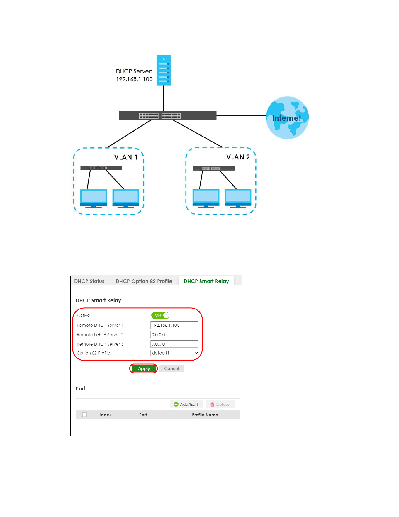
Chapter 63 DHCP
XGS2220 Series User’s Guide
472
Figure 377 DHCP Smart Relay Network Example
Configure the NETWORKING > DHCP > DHCPv4 Relay > DHCP Smart Relay screen as shown. Make sure
you select a DHCP option 82 profile (default1 in this example) to set the Switch to send additional
information (such as the VLAN ID) together with the DHCP requests to the DHCP server. This allows the
DHCP server to assign the appropriate IP address according to the VLAN ID. Click Apply after you finish
the configuration.
Figure 378 DHCP Relay Configuration Example
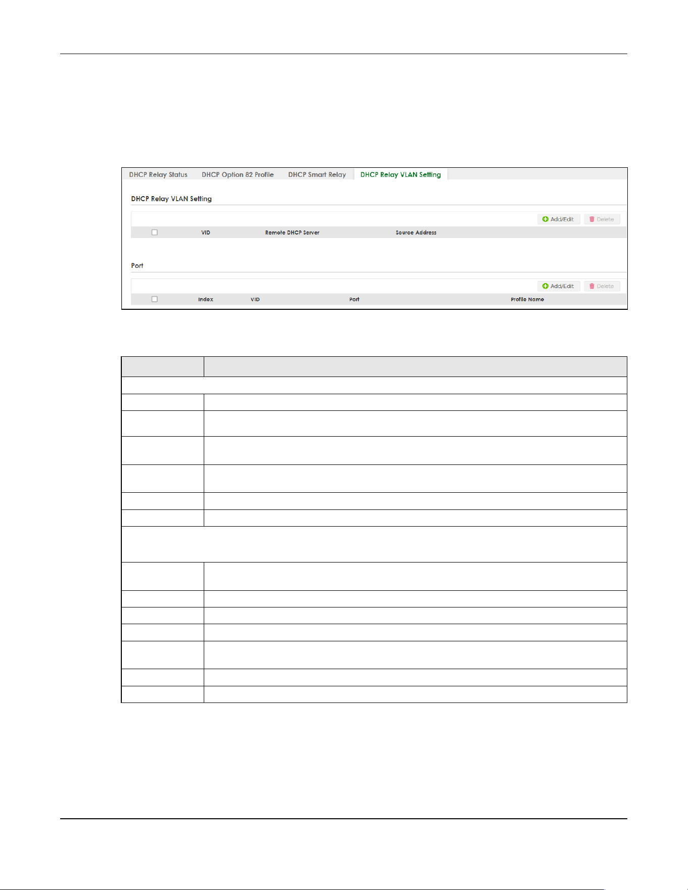
Chapter 63 DHCP
XGS2220 Series User’s Guide
473
63.5 DHCPv4 VLAN Setting
Use this screen to configure your DHCP settings based on the VLAN domain of the DHCP clients. Click
NETWORKING > DHCP > DHCPv4 Relay > DHCP Relay VLAN Setting to display the screen as shown.
Figure 379 NETWORKING > DHCP > DHCPv4 Relay > DHCP Relay VLAN Setting
The following table describes the labels in this screen.
63.5.1 Add/Edit DHCPv4 VLAN Setting
Use this screen to add/edit your DHCP settings based on the VLAN domain of the DHCP clients. Click the
Add/Edit button in the DHCP Relay VLAN Setting section of the NETWORKING > DHCP > DHCPv4 Relay >
DHCP Relay VLAN Setting screen to access this screen.
Table 241 NETWORKING > DHCP > DHCPv4 Relay > DHCP Relay VLAN Setting
LABEL DESCRIPTION
DHCP Relay VLAN Setting
VID This field displays the ID number of the VLAN group to which this DHCP settings apply.
Remote
DHCP Server
This displays the IP address of a DHCP server in dotted decimal notation.
Source
Address
This field displays the source IP address you configured for DHCP requests from clients on this
VLAN.
Select an entry’s check box to select a specific entry. Otherwise, select the check box in the
table heading row to select all entries.
Add/Edit Click Add/Edit to add a new entry or edit a selected one.
Delete Click Delete to remove the selected entries.
Port
Use this section to apply a different DHCP option 82 profile to certain ports in a VLAN.
Index This field displays a sequential number for each entry. Click an index number to change the
settings.
VID This field displays the VLAN to which the ports belongs.
Port This field displays the ports to which the Switch applies the settings.
Profile Name This field displays the DHCP option 82 profile that the Switch applies to the ports in this VLAN.
Select an entry’s check box to select a specific entry. Otherwise, select the check box in the
table heading row to select all entries.
Add/Edit Click Add/Edit to add a new entry or edit a selected one.
Delete Click Delete to remove the selected entries.
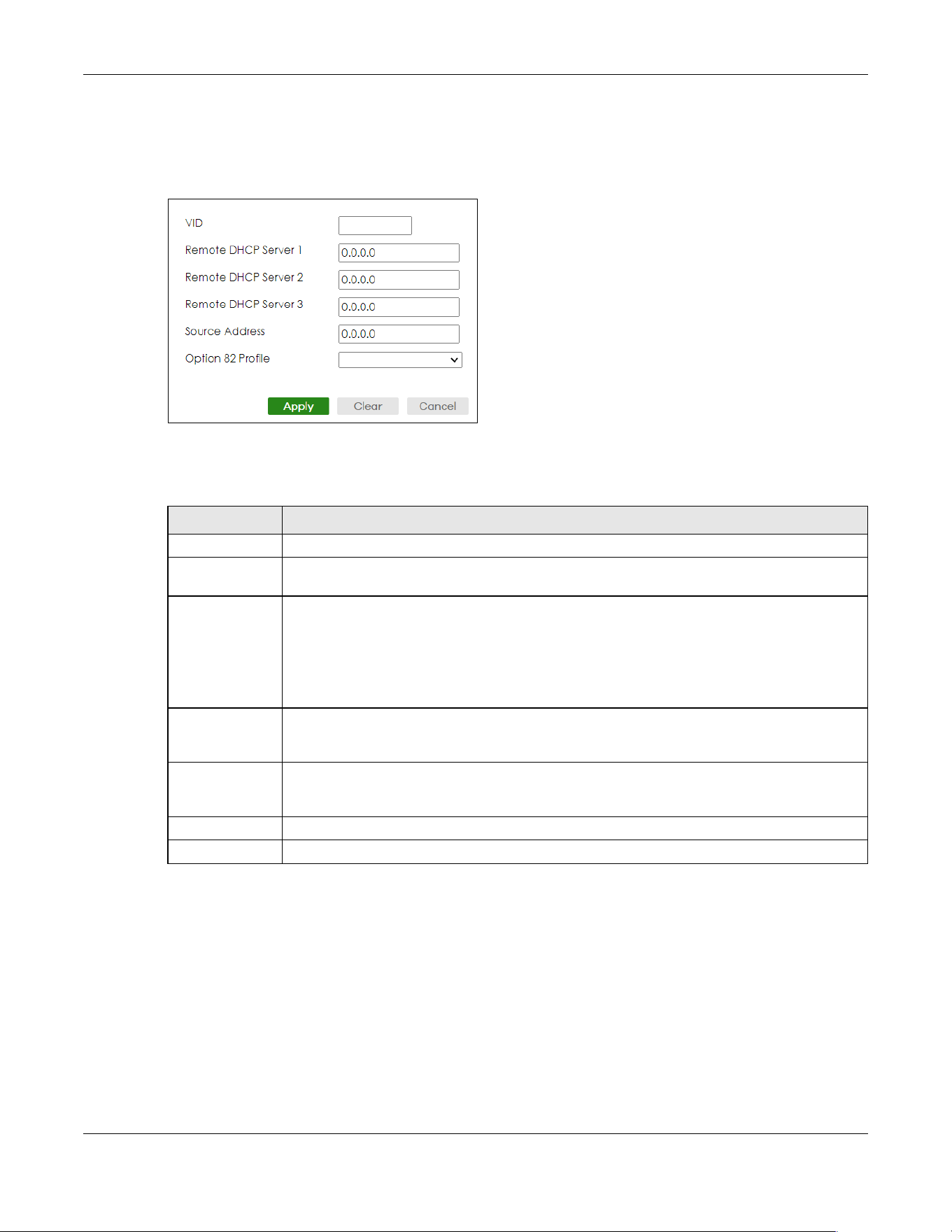
Chapter 63 DHCP
XGS2220 Series User’s Guide
474
Note: You must set up a management IP address for each VLAN that you want to configure
DHCP settings for on the Switch.
Figure 380 NETWORKING > DHCP > DHCPv4 Relay > DHCP Relay VLAN Setting > Add/Edit (DHCP Relay
VLAN Setting)
The following table describes the labels in this screen.
63.5.2 Add/Edit DHCPv4 VLAN Port
Use this screen to apply a different DHCP option 82 profile to certain ports in a VLAN. Click the Add/Edit
button in the Port section of the NETWORKING > DHCP > DHCPv4 Relay > DHCP Relay VLAN Setting
screen to access this screen.
Table 242 NETWORKING > DHCP > DHCPv4 Relay > DHCP Relay VLAN Setting > Add/Edit (DHCP Relay
VLAN Setting)
LABEL DESCRIPTION
VID Enter the ID number of the VLAN to which these DHCP settings apply.
Remote DHCP
Server 1 .. 3
Enter the IP address of a DHCP server in dotted decimal notation.
Source Address Enter the source IP address that the Switch adds to DHCP requests from clients on this VLAN
before forwarding them. If you leave this field set to 0.0.0.0, the Switch automatically sets the
source IP address of the DHCP requests to the IP address of the interface on which the packet is
received.
The source IP address helps DHCP clients obtain an appropriate IP address when you configure
multiple routing domains on a VLAN.
Option 82 Profile Select a pre-defined DHCP option 82 profile that the Switch applies to all ports in this VLAN. The
Switch adds the Circuit ID sub-option and/or Remote ID sub-option specified in the profile to
DHCP requests that it relays to a DHCP server.
Apply Click Apply to save your changes to the Switch’s run-time memory. The Switch loses these
changes if it is turned off or loses power, so use the Save link on the top navigation panel to save
your changes to the non-volatile memory when you are done configuring.
Clear Click Clear to clear the fields to the factory defaults.
Cancel Click Cancel to not save the configuration you make and return to the last screen.
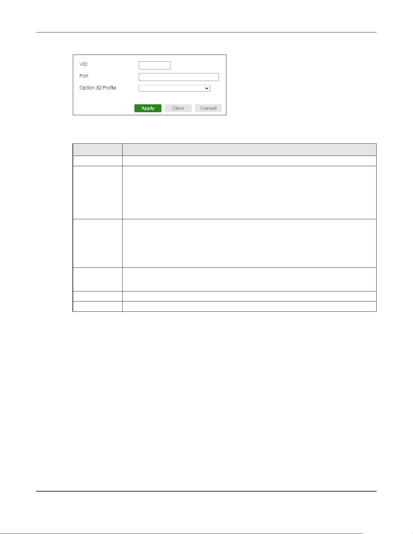
Chapter 63 DHCP
XGS2220 Series User’s Guide
475
Figure 381 NETWORKING > DHCP > DHCPv4 Relay > DHCP Relay VLAN Setting > Add/Edit (Port)
The following table describes the labels in this screen.
63.6 DHCPv6 Relay
A DHCPv6 relay agent is on the same network as the DHCPv6 clients and helps forward messages
between the DHCPv6 server (that is in another network) and the DHCPv6 clients.
The DHCPv6 relay agent can add the remote identification (remote-ID) option and the interface-ID
option to the Relay-Forward DHCPv6 messages. The remote-ID option carries a user-defined string, such
as the system name. The interface-ID option provides slot number, port information and the VLAN ID to
the DHCPv6 server. The remote-ID option (if any) is stripped from the Relay-Reply messages before the
relay agent sends the packets to the clients. The DHCPv6 server copies the interface-ID option from the
Relay-Forward message into the Relay-Reply message and sends it to the relay agent. The interface-ID
should not change even after the relay agent restarts.
Use this screen to view and configure DHCPv6 relay settings for a specific VLAN on the Switch. Click
NETWORKING > DHCP > DHCPv6 Relay in the navigation panel to display the screen as shown.
Table 243 NETWORKING > DHCP > DHCPv4 Relay > DHCP Relay VLAN Setting > Add/Edit (Port)
LABEL DESCRIPTION
VID Enter the ID number of the VLAN you want to configure here.
Port Enter the number of ports to which you want to apply the specified DHCP option 82 profile.
You can enter multiple ports separated by (no space) comma (,) or hyphen (-) for a range. For
example, enter “3-5” for ports 3, 4, and 5. Enter “3,5,7” for ports 3, 5, and 7.
In Stacking mode, the first number represents the slot and the second the port number. Enter 1/
1-1/24,2/28 for ports 1 to 24 for the Switch in slot 1 and port 28 for the Switch in slot 2, for
example.
Option 82 Profile Select a pre-defined DHCP option 82 profile that the Switch applies to the specified ports in this
VLAN. The Switch adds the Circuit ID sub-option and/or Remote ID sub-option specified in the
profile to DHCP requests that it relays to a DHCP server.
The profile you select here has priority over the one you select in the NETWORKING > DHCP >
DHCPv4 Relay > DHCP Relay VLAN Setting (the DHCP Relay VLAN Setting section)> Add/Edit
screen.
Apply Click Apply to save your changes to the Switch’s run-time memory. The Switch loses these
changes if it is turned off or loses power, so use the Save link on the top navigation panel to save
your changes to the non-volatile memory when you are done configuring.
Clear Click Clear to clear the fields to the factory defaults.
Cancel Click Cancel to not save the configuration you make and return to the last screen.

Chapter 63 DHCP
XGS2220 Series User’s Guide
476
Figure 382 NETWORKING > DHCP > DHCPv6 Relay
The following table describes the labels in this screen.
63.6.1 Add/Edit DHCPv6 Relay
Use this screen to add/edit DHCPv6 relay settings for a specific VLAN on the Switch. Click Add/Edit, or
select an entry and click Add/Edit in the NETWORKING > DHCP > DHCPv6 Relay screen to display this
screen.
Figure 383 NETWORKING > DHCP > DHCPv6 Relay > Add/Edit
Table 244 NETWORKING > DHCP > DHCPv6 Relay
LABEL DESCRIPTION
VID This field displays the VLAN ID number.
Helper Address This field displays the IPv6 address of the remote DHCPv6 server for this VLAN.
Interface ID This field displays whether the interface-ID option is added to DHCPv6 requests from clients in this
VLAN.
Remote ID This field displays whether the remote-ID option is added to DHCPv6 requests from clients in this
VLAN.
Select an entry’s check box to select a specific entry. Otherwise, select the check box in the
table heading row to select all entries.
Add/Edit Click Add/Edit to add a new entry or edit a selected one.
Delete Click Delete to remove the selected entries.

Chapter 63 DHCP
XGS2220 Series User’s Guide
477
The following table describes the labels in this screen.
63.7 DHCP Server Guard
Use this screen to specify whether ports are trusted or untrusted ports for DHCP packets. Click
NETWORKING > DHCP > DHCP Server Guard in the navigation panel to display the screen as shown.
Table 245 NETWORKING > DHCP > DHCPv6 Relay > Add/Edit
LABEL DESCRIPTION
VID Enter the ID number of the VLAN to which the DHCPv6 server that will assign IP information
belongs here.
Helper Address Enter the IPv6 address of the DHCPv6 server that will assign IP information here.
An 128-bit IPv6 address is written as eight 16-bit hexadecimal blocks separated by colons (:). This
is an example IPv6 address ‘2001:0db8:1a2b:0015:0000:0000:1a2f:0000’.
IPv6 addresses can be abbreviated in two ways:
• Leading zeros in a block can be omitted. So ‘2001:0db8:1a2b:0015:0000:0000:1a2f:0000’ can
be written as ‘2001:db8:1a2b:15:0:0:1a2f:0’.
• Any number of consecutive blocks of zeros can be replaced by a double colon. A double
colon can only appear once in an IPv6 address. So
‘2001:0db8:0000:0000:1a2f:0000:0000:0015’ can be written as
‘2001:0db8::1a2f:0000:0000:0015’, ‘2001:0db8:0000:0000:1a2f::0015’, ‘2001:db8::1a2f:0:0:15’
or ‘2001:db8:0:0:1a2f::15’.
Interface ID Enable the switch button to have the Switch add the interface-ID option in the DHCPv6 requests
from the clients in the specified VLAN before the Switch forwards them to a DHCPv6 server.
Remote ID Enter a string of up to 64 printable ASCII characters (except [ ? ], [ | ], [ ' ], [ " ] or [ , ]) to be
carried in the remote-ID option. The Switch adds the remote-ID option in the DHCPv6 requests
from the clients in the specified VLAN before the Switch forwards them to a DHCPv6 server.
Apply Click Apply to save your changes to the Switch’s run-time memory. The Switch loses these
changes if it is turned off or loses power, so use the Save link on the top navigation panel to save
your changes to the non-volatile memory when you are done configuring.
Clear Click Clear to clear the fields to the factory defaults.
Cancel Click Cancel to not save the configuration you make and return to the last screen.

Chapter 63 DHCP
XGS2220 Series User’s Guide
478
Figure 384 NETWORKING > DHCP > DHCP Server Guard (Standalone Mode)
Figure 385 NETWORKING > DHCP > DHCP Server Guard (Stacking Mode)
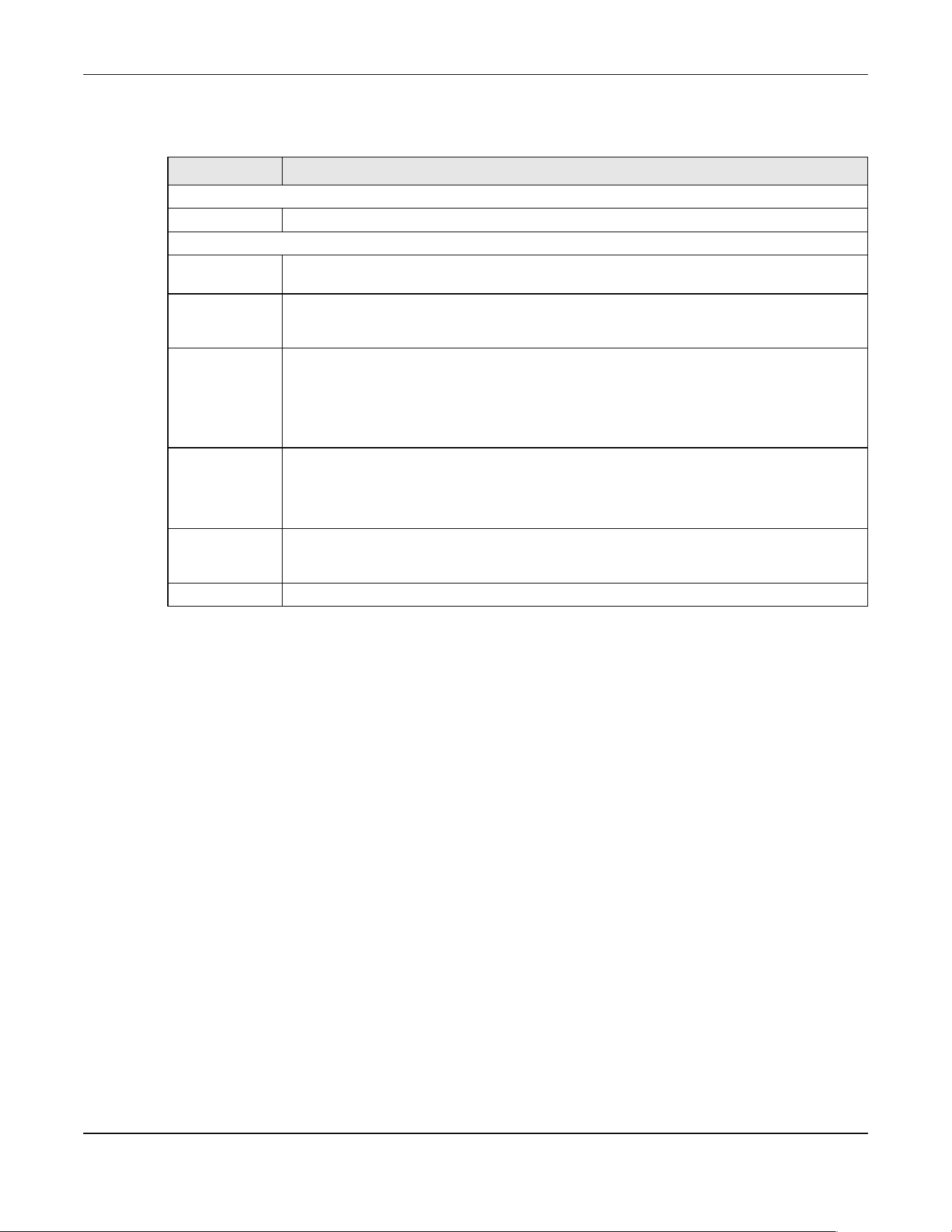
Chapter 63 DHCP
XGS2220 Series User’s Guide
479
The following table describes the labels in this screen.
Table 246 NETWORKING > DHCP > DHCP Server Guard
LABEL DESCRIPTION
DHCP Server Guard
Active Enable the switch button to enable DHCP Server Guard.
Port Setting
SLOT This field appears only in Stacking mode. Click the drop-down list to choose the slot number of
the Switch in a stack.
Port This field displays the port number. In Stacking mode, the first number represents the slot ID and
the second is the port number. Please note that the default stacking ports (the last four ports of
your Switch) cannot be configured. They are reserved for stacking only.
* Settings in this row apply to all ports.
Use this row only if you want to make some settings the same for all ports. Use this row first to set
the common settings and then make adjustments on a port-by-port basis.
Note: Changes in this row are copied to all the ports as soon as you make them.
Trusted State Select whether this port is a trusted port (Trusted) or an untrusted port (Untrusted). The Switch
does not discard DHCP packets on trusted ports for any reason.
The Switch discards DHCP packets from untrusted ports when the packet is a DHCP server
packet (for example, OFFER, ACK, or NACK).
Apply Click Apply to save your changes to the Switch’s run-time memory. The Switch loses these
changes if it is turned off or loses power, so use the Save link on the top navigation panel to save
your changes to the non-volatile memory when you are done configuring.
Cancel Click Cancel to reset the fields to their last saved values.
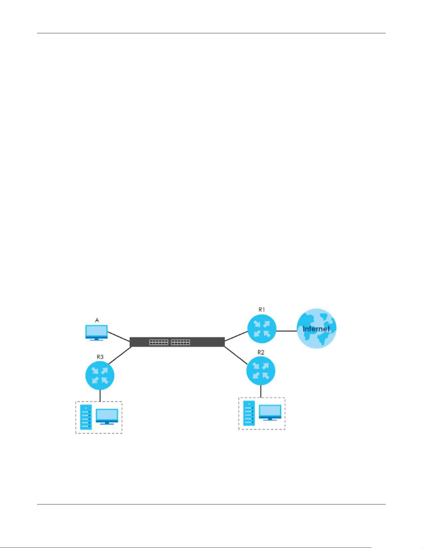
Chapter 64 Static Route
XGS2220 Series User’s Guide
480
CHAPTER 64
Static Route
64.1 Static Routing Overview
This chapter shows you how to configure static routes.
The Switch uses IP for communication with management computers, for example using HTTP, Telnet, SSH,
or SNMP. Use IP static routes to have the Switch respond to remote management stations that are not
reachable through the default gateway. The Switch can also use static routes to send data to a server
or device that is not reachable through the default gateway, for example when sending SNMP traps or
using ping to test IP connectivity.
The Switch usually uses the default gateway to route outbound traffic from computers on the LAN to the
Internet. To have the Switch send data to devices not reachable through the default gateway, use
static routes.
For example, the next figure shows a computer (A) connected to the Switch. The Switch routes most
traffic from A to the Internet through the Switch’s default gateway (R1). You create one static route to
connect to services offered by your ISP behind router R2. You create another static route to
communicate with a separate network behind a router R3 connected to the Switch.
Figure 386 Example of Static Routing Topology
64.1.1 What You Can Do
Use the IPv4 Static Route screen (Section 64.2 on page 481) to configure and enable an IPv4 static route.
Use the IPv6 Static Route screen (Section 64.3 on page 482) to configure and enable an IPv6 static route.
N1

Chapter 64 Static Route
XGS2220 Series User’s Guide
481
64.2 IPv4 Static Route
Click NETWORKING > Static Routing > IPv4 Static Route to display the screen as shown.
Figure 387 NETWORKING > Static Routing > IPv4 Static Route
The following table describes the related labels you use to create a static route.
64.2.1 Add/Edit IPv4 Static Route
Click Add/Edit, or select an entry and click Add/Edit in the NETWORKING > Static Routing > IPv4 Static
Route screen to display this screen.
Figure 388 NETWORKING > Static Routing > IPv4 Static Route > Add/Edit
Table 247 NETWORKING > Static Routing > IPv4 Static Route
LABEL DESCRIPTION
Index This field displays the index number of the route.
Active This field displays whether the static route is activated or not.
Name This field displays the descriptive name for this route. This is for identification purposes only.
Destination
Address
This field displays the IP network address of the final destination.
Subnet Mask This field displays the subnet mask for this destination.
Gateway
Address
This field displays the IP address of the gateway. The gateway is an immediate neighbor of your
Switch that will forward the packet to the destination.
Metric This field displays the cost of transmission for routing purposes.
Select an entry’s check box to select a specific entry. Otherwise, select the check box in the
table heading row to select all entries.
Add/Edit Click Add/Edit to add a new entry or edit a selected one.
Delete Click Delete to remove the selected entries.
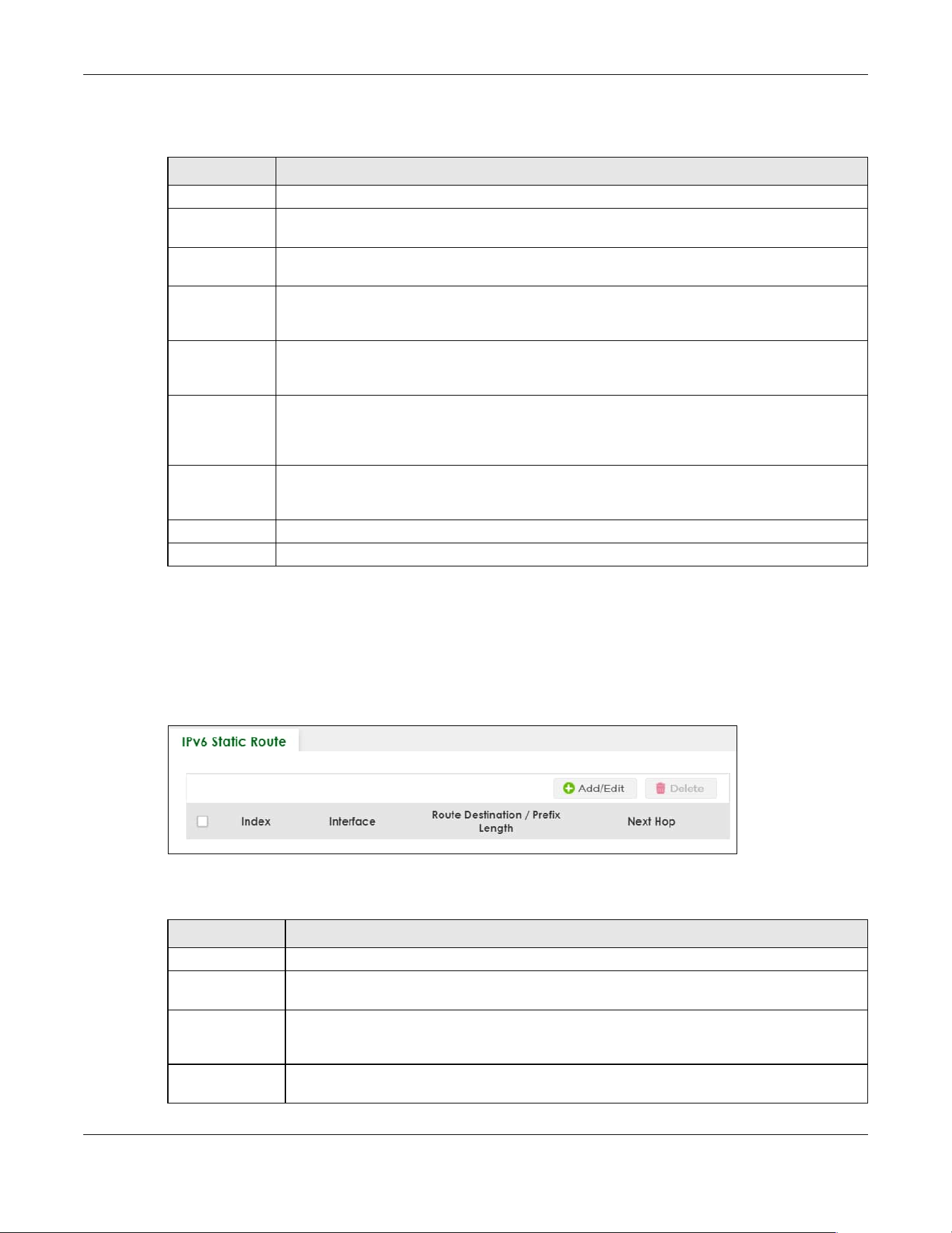
Chapter 64 Static Route
XGS2220 Series User’s Guide
482
The following table describes the related labels you use to create a static route.
64.3 IPv6 Static Route
Click NETWORKING > Static Routing > IPv6 Static Route to display the screen as shown.
Figure 389 NETWORKING > Static Routing > IPv6 Static Route
The following table describes the related labels you use to create a static route.
Table 248 NETWORKING > Static Routing > IPv4 Static Route > Add/Edit
LABEL DESCRIPTION
Active This field allows you to activate or deactivate this static route.
Name Enter a descriptive name (up to 10 printable ASCII characters except [ ? ], [ | ], [ ' ], [ " ] or [ , ]) for
identification purposes.
Destination IP
Address
This parameter specifies the IP network address of the final destination.
IP Subnet Mask Enter the subnet mask for this destination. Routing is always based on network number. If you
need to specify a route to a single host, use a subnet mask of 255.255.255.255 in the subnet mask
field to force the network number to be identical to the host ID.
Gateway IP
Address
Enter the IP address of the gateway. The gateway is an immediate neighbor of your Switch that
will forward the packet to the destination. The gateway must be a router on the same segment
as your Switch.
Metric The metric represents the “cost” of transmission for routing purposes. IP routing uses hop count as
the measurement of cost, with a minimum of 1 for directly connected networks. Enter a number
that approximates the cost for this link. The number need not be precise, but it must be between
1 and 15. In practice, 2 or 3 is usually a good number.
Apply Click Apply to save your changes to the Switch’s run-time memory. The Switch loses these
changes if it is turned off or loses power, so use the Save link on the top navigation panel to save
your changes to the non-volatile memory when you are done configuring.
Clear Click Clear to clear the fields to the factory defaults.
Cancel Click Cancel to not save the configuration you make and return to the last screen.
Table 249 NETWORKING > Static Routing > IPv6 Static Route
LABEL DESCRIPTION
Index This field displays the index number of the route.
Interface This field displays the descriptive name of the interface that is used to forward the packets to
the destination.
Route
Destination /
Prefix Length
This field displays the IPv6 subnet prefix and prefix length of the final destination.
Next Hop This field displays the IPv6 address of the gateway that helps forward the packet to the
destination.
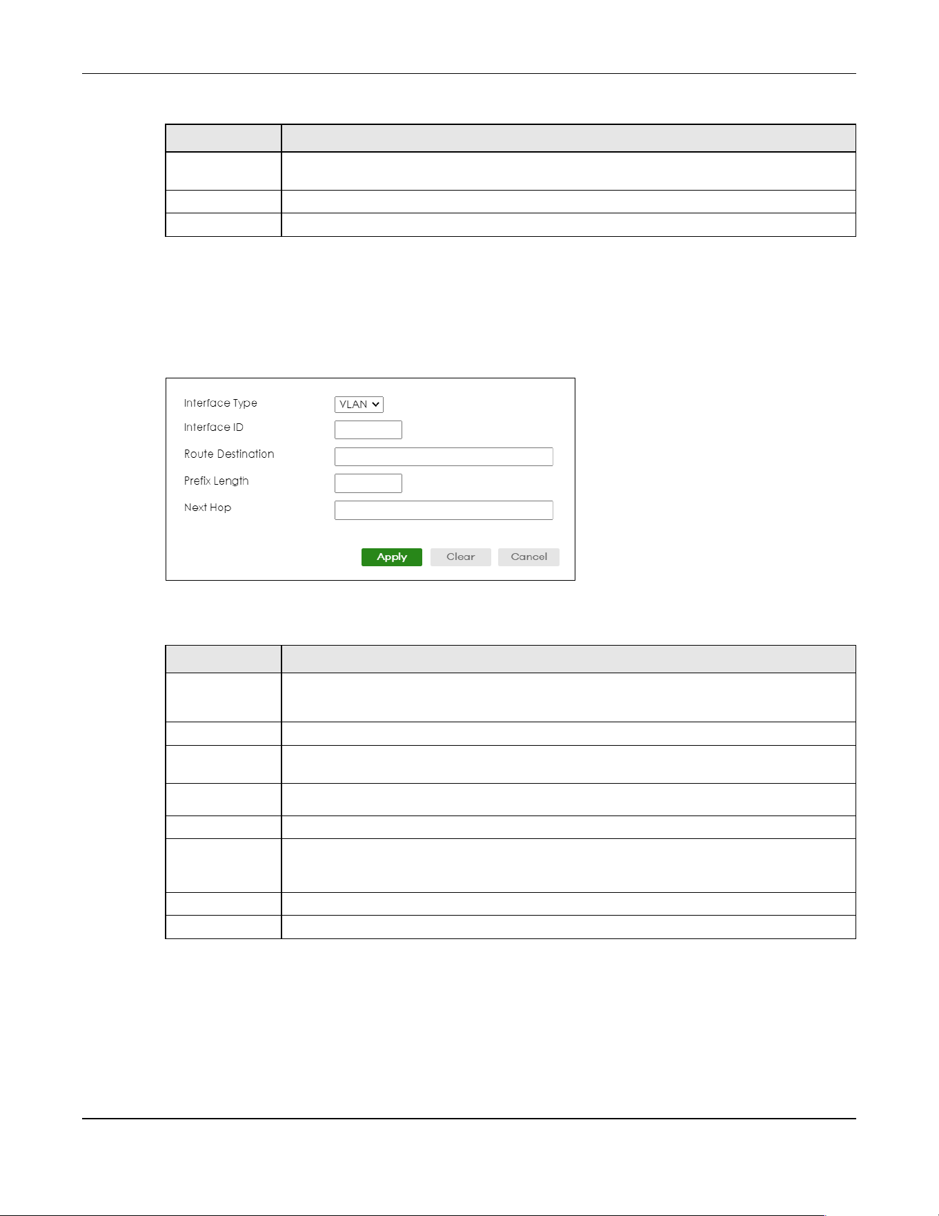
Chapter 64 Static Route
XGS2220 Series User’s Guide
483
64.3.1 Add/Edit IPv6 Static Route
Click Add/Edit, or select an entry and click Add/Edit in the NETWORKING > Static Routing > IPv6 Static
Route to display this screen.
Figure 390 NETWORKING > Static Routing > IPv6 Static Route > Add/Edit
The following table describes the related labels you use to create a static route.
Select an entry’s check box to select a specific entry. Otherwise, select the check box in the
table heading row to select all entries.
Add/Edit Click Add/Edit to add a new entry or edit a selected one.
Delete Click Delete to remove the selected entries.
Table 249 NETWORKING > Static Routing > IPv6 Static Route (continued)
LABEL DESCRIPTION
Table 250 NETWORKING > Static Routing > IPv6 Static Route > Add/Edit
LABEL DESCRIPTION
Interface Type Select the type of the IPv6 interface through which the IPv6 packets are forwarded.
The Switch supports only the VLAN interface type at the time of writing.
Interface ID Enter the ID number of the IPv6 interface through which the IPv6 packets are forwarded.
Route
Destination
Enter the IPv6 address of the final destination.
Prefix Length Enter the prefix length number of up to 64 for this destination.
Next Hop Enter the IPv6 address of the next-hop router.
Apply Click Apply to save your changes to the Switch’s run-time memory. The Switch loses these
changes if it is turned off or loses power, so use the Save link on the top navigation panel to
save your changes to the non-volatile memory when you are done configuring.
Clear Click Clear to clear the fields to the factory defaults.
Cancel Click Cancel to not save the configuration you make and return to the last screen.

XGS2220 Series User’s Guide
484
CHAPTER 65
SECURITY
The following chapters introduces the configurations of the links under the SECURITY navigation panel.
Quick links to chapters:
• AAA
• Access Control
• Classifier
• Policy Rule
• Anti-Arpscan
• BPDU Guard
• Storm Control
• Error-Disable
• IP Source Guard
• DHCP Snooping
• ARP Inspection
• IPv6 Source Guard
• Port Authentication
• Port Security
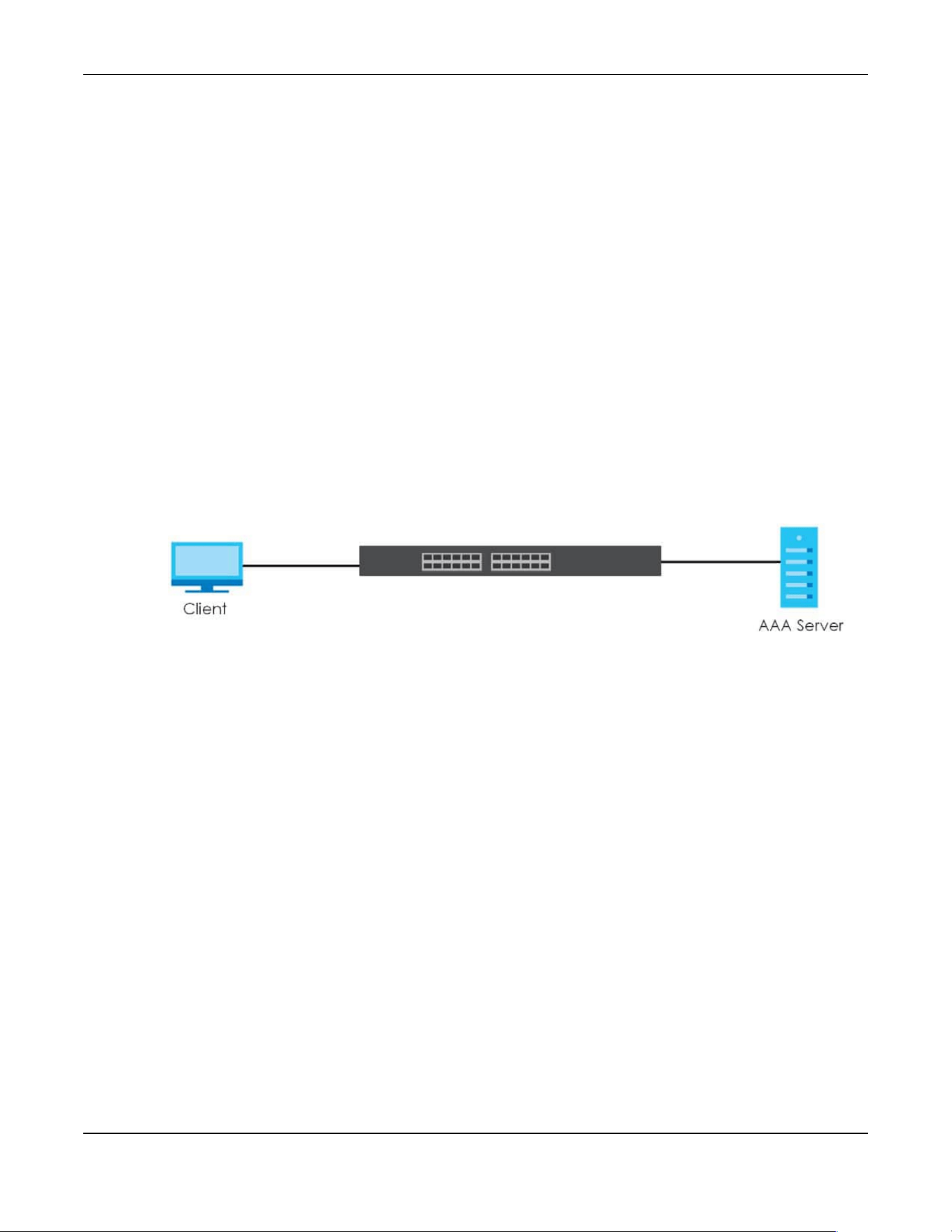
Chapter 66 AAA
XGS2220 Series User’s Guide
485
CHAPTER 66
AAA
66.1 Authentication, Authorization and Accounting (AAA)
This chapter describes how to configure authentication, authorization and accounting settings on the
Switch.
The external servers that perform authentication, authorization and accounting functions are known as
AAA servers. The Switch supports RADIUS (Remote Authentication Dial-In User Service) and TACACS+
(Terminal Access Controller Access-Control System Plus) as the external authentication, authorization,
and accounting server.
Figure 391 AAA Server
66.1.1 What You Can Do
• use the RADIUS Server Setup screen (Section 66.2 on page 486) to configure your RADIUS server
settings.
• Use the TACACS+ Server Setup screen (Section 66.3 on page 488) to configure your TACACS+
authentication settings.
• Use the AAA Setup screen (Section 66.4 on page 490) to configure authentication, authorization and
accounting settings, such as the methods used to authenticate users accessing the Switch and which
database the Switch should use first.
66.1.2 What You Need to Know
Authentication is the process of determining who a user is and validating access to the Switch. The
Switch can authenticate users who try to log in based on user accounts configured on the Switch itself.
The Switch can also use an external authentication server to authenticate a large number of users.
Authorization is the process of determining what a user is allowed to do. Different user accounts may
have higher or lower privilege levels associated with them. For example, user A may have the right to
create new login accounts on the Switch but user B cannot. The Switch can authorize users based on
user accounts configured on the Switch itself or it can use an external server to authorize a large number
of users.
Accounting is the process of recording what a user is doing. The Switch can use an external server to
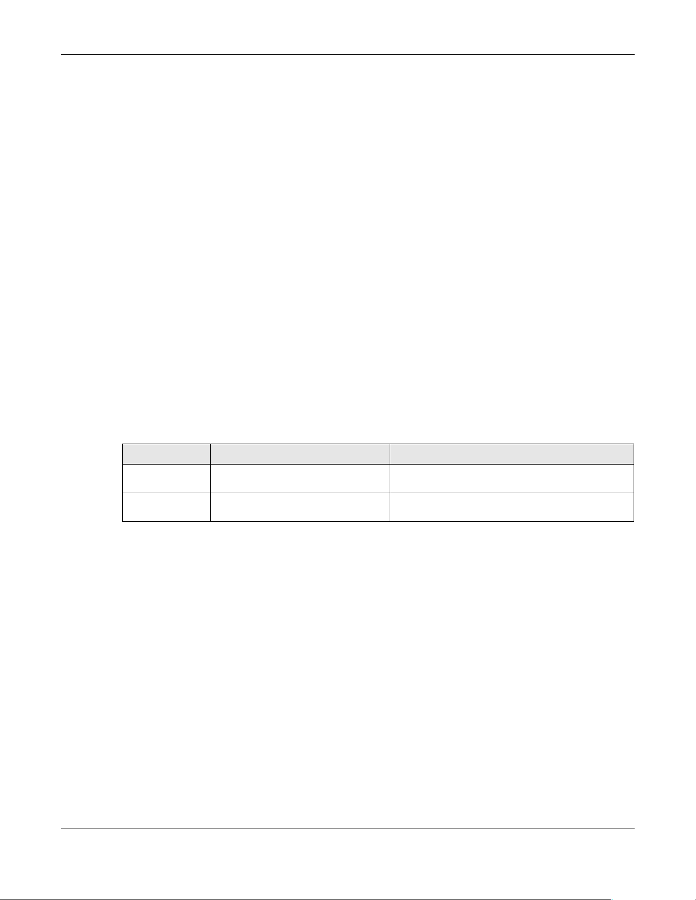
Chapter 66 AAA
XGS2220 Series User’s Guide
486
track when users log in, log out, execute commands and so on. Accounting can also record system
related actions such as boot up and shut down times of the Switch.
Local User Accounts
By storing user profiles locally on the Switch, your Switch is able to authenticate and authorize users
without interacting with a network AAA server. However, there is a limit on the number of users you may
authenticate in this way.
RADIUS
RADIUS is a security protocol used to authenticate users by means of an external server instead of (or in
addition to) an internal device user database that is limited to the memory capacity of the device. In
essence, RADIUS authentication allows you to validate an unlimited number of users from a central
location.
RADIUS and TACACS+
RADIUS and TACACS+ are security protocols used to authenticate users by means of an external server
instead of (or in addition to) an internal device user database that is limited to the memory capacity of
the device. In essence, RADIUS and TACACS+ authentication both allow you to validate an unlimited
number of users from a central location.
The following table describes some key differences between RADIUS and TACACS+.
66.2 RADIUS Server Setup
Use this screen to configure your RADIUS server settings. Click SECURITY > AAA > RADIUS Server Setup to
view the screen as shown.
Table 251 RADIUS vs. TACACS+
RADIUS TACACS+
Transport
Protocol
UDP (User Datagram Protocol) TCP (Transmission Control Protocol)
Encryption Encrypts the password sent for
authentication.
All communication between the client (the Switch)
and the TACACS server is encrypted.
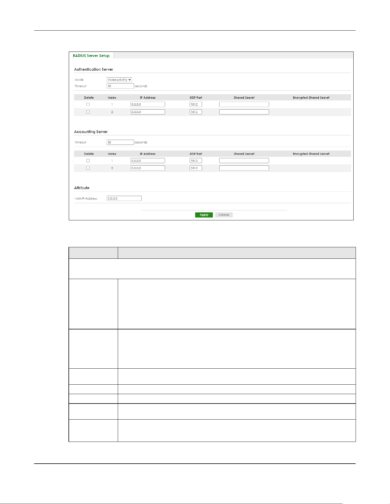
Chapter 66 AAA
XGS2220 Series User’s Guide
487
Figure 392 SECURITY > AAA > RADIUS Server Setup
The following table describes the labels in this screen.
Table 252 SECURITY > AAA > RADIUS Server Setup
LABEL DESCRIPTION
Authentication Server
Use this section to configure your RADIUS authentication settings.
Mode This field is only valid if you configure multiple RADIUS servers.
Select index-priority and the Switch tries to authenticate with the first configured RADIUS server,
if the RADIUS server does not respond then the Switch tries to authenticate with the second
RADIUS server.
Select round-robin to alternate between the RADIUS servers that it sends authentication
requests to.
Timeout Specify the amount of time in seconds that the Switch waits for an authentication request
response from the RADIUS server.
If you are using two RADIUS servers then the timeout value is divided between the two RADIUS
servers. For example, if you set the timeout value to 30 seconds, then the Switch waits for a
response from the first RADIUS server for 15 seconds and then tries the second RADIUS server.
Delete Check this box if you want to remove an existing RADIUS server entry from the Switch. This entry
is deleted when you click Apply.
Index This is a read-only number representing a RADIUS server entry.
IP Address Enter the IPv4 address or IPv6 address of an external RADIUS server.
UDP Port The default port of a RADIUS server for authentication is 1812. You need not change this value
unless your network administrator instructs you to do so.
Shared Secret Specify a password (up to 32 alphanumeric characters except [ ? ], [ | ], [ ' ], [ " ], [ space ], or [
, ]) as the key to be shared between the external RADIUS server and the Switch. This key is not
sent over the network. This key must be the same on the external RADIUS server and the Switch.
Chapter 66 AAA
XGS2220 Series User’s Guide
488
66.3 TACACS+ Server Setup
Use this screen to configure your TACACS+ server settings. Click SECURITY > AAA > TACACS+ Server Setup
to view the screen as shown.
Encrypted
Shared Secret
This displays the encrypted shared secret in ‘*’ format if you enabled Server Key Encryption in
SECURITY > AAA > AAA Setup.
Note: If you forget the key you set, simply reset the key in the Shared Secret field. If a
key is encrypted, it will remain in the encrypted format even if you later disable
Server Key Encryption in SECURITY > AAA > AAA Setup.
Note: The shared secret displayed in this field does not present the actual length of
the shared secret.
Accounting Server
Use this section to configure your RADIUS accounting server settings.
Timeout Specify the amount of time in seconds that the Switch waits for an accounting request
response from the RADIUS accounting server.
Delete Check this box if you want to remove an existing RADIUS accounting server entry from the
Switch. This entry is deleted when you click Apply.
Index This is a read-only number representing a RADIUS accounting server entry.
IP Address Enter the IPv4 address or IPv6 address of an external RADIUS accounting server.
UDP Port The default port of a RADIUS accounting server for accounting is 1813. You need not change
this value unless your network administrator instructs you to do so.
Shared Secret Specify a password (up to 32 alphanumeric characters except [ ? ], [ | ], [ ' ], [ " ], [ space ], or [
, ]) as the key to be shared between the external RADIUS accounting server and the Switch.
This key is not sent over the network. This key must be the same on the external RADIUS
accounting server and the Switch.
Encrypted
Shared Secret
This displays the encrypted shared secret in ‘*’ format if you enabled Server Key Encryption in
SECURITY > AAA > AAA Setup.
Note: If you forget the key you set, simply reset the key in the Shared Secret field. If a
key is encrypted, it will remain in the encrypted format even if you later disable
Server Key Encryption in SECURITY > AAA > AAA Setup.
Note: The shared secret displayed in this field does not present the actual length of
the shared secret.
Attribute
Use this section to define the RADIUS server attribute for its account.
NAS-IP-Address Enter the IP address of the NAS (Network Access Server).
Apply Click Apply to save your changes to the Switch’s run-time memory. The Switch loses these
changes if it is turned off or loses power, so use the Save link on the top navigation panel to
save your changes to the non-volatile memory when you are done configuring.
Cancel Click Cancel to begin configuring this screen afresh.
Table 252 SECURITY > AAA > RADIUS Server Setup (continued)
LABEL DESCRIPTION

Chapter 66 AAA
XGS2220 Series User’s Guide
489
Figure 393 SECURITY > AAA > TACACS+ Server Setup
The following table describes the labels in this screen.
Table 253 SECURITY > AAA > TACACS+ Server Setup
LABEL DESCRIPTION
Authentication Server
Use this section to configure your TACACS+ authentication settings.
Mode This field is only valid if you configure multiple TACACS+ servers.
Select index-priority and the Switch tries to authenticate with the first configured TACACS+
server, if the TACACS+ server does not respond then the Switch tries to authenticate with the
second TACACS+ server.
Select round-robin to alternate between the TACACS+ servers that it sends authentication
requests to.
Timeout Specify the amount of time in seconds that the Switch waits for an authentication request
response from the TACACS+ server.
If you are using index-priority for your authentication and you are using two TACACS+ servers
then the timeout value is divided between the two TACACS+ servers. For example, if you set
the timeout value to 30 seconds, then the Switch waits for a response from the first TACACS+
server for 15 seconds and then tries the second TACACS+ server.
Delete Check this box if you want to remove an existing TACACS+ server entry from the Switch. This
entry is deleted when you click Apply.
Index This is a read-only number representing a TACACS+ server entry.
IP Address Enter the IP address of an external TACACS+ server in dotted decimal notation.
TCP Port The default port of a TACACS+ server for authentication is 49. You need not change this value
unless your network administrator instructs you to do so.
Chapter 66 AAA
XGS2220 Series User’s Guide
490
66.4 AAA Setup
Use this screen to configure authentication, authorization and accounting settings on the Switch. Click
SECURITY > AAA > AAA Setup to view the screen as shown.
Shared Secret Specify a password (up to 32 alphanumeric characters except [ ? ], [ | ], [ ' ], [ " ], [ space ], or
[ , ]) as the key to be shared between the external TACACS+ server and the Switch. This key is
not sent over the network. This key must be the same on the external TACACS+ server and the
Switch.
Encrypted
Shared Secret
This displays the encrypted shared secret in ‘*’ format if you enabled Server Key Encryption in
SECURITY > AAA > AAA Setup.
Note: If you forget the key you set, simply reset the key in the Shared Secret field. If a
key is encrypted, it will remain in the encrypted format even if you later
disable Server Key Encryption in SECURITY > AAA > AAA Setup.
Note: The shared secret displayed in this field does not present the actual length of
the shared secret.
Accounting Server
Use this section to configure your TACACS+ accounting settings.
Timeout Specify the amount of time in seconds that the Switch waits for an accounting request
response from the TACACS+ server.
Delete Check this box if you want to remove an existing TACACS+ accounting server entry from the
Switch. This entry is deleted when you click Apply.
Index This is a read-only number representing a TACACS+ accounting server entry.
IP Address Enter the IP address of an external TACACS+ accounting server in dotted decimal notation.
TCP Port The default port of a TACACS+ accounting server is 49. You need not change this value unless
your network administrator instructs you to do so.
Shared Secret Specify a password (up to 32 alphanumeric characters except [ ? ], [ | ], [ ' ], [ " ], [ space ], or
[ , ]) as the key to be shared between the external TACACS+ accounting server and the Switch.
This key is not sent over the network. This key must be the same on the external TACACS+
accounting server and the Switch.
Encrypted
Shared Secret
This displays the encrypted shared secret in ‘*’ format if you enabled Server Key Encryption in
SECURITY > AAA > AAA Setup.
Note: If you forget the key you set, simply reset the key in the Shared Secret field. If a
key is encrypted, it will remain in the encrypted format even if you later
disable Server Key Encryption in SECURITY > AAA > AAA Setup.
Note: The shared secret displayed in this field does not present the actual length of
the shared secret.
Apply Click Apply to save your changes to the Switch’s run-time memory. The Switch loses these
changes if it is turned off or loses power, so use the Save link on the top navigation panel to
save your changes to the non-volatile memory when you are done configuring.
Cancel Click Cancel to begin configuring this screen afresh.
Table 253 SECURITY > AAA > TACACS+ Server Setup (continued)
LABEL DESCRIPTION

Chapter 66 AAA
XGS2220 Series User’s Guide
491
Figure 394 SECURITY > AAA > AAA Setup
The following table describes the labels in this screen.
Table 254 SECURITY > AAA > AAA Setup
LABEL DESCRIPTION
Server Key Encryption
Use this section to configure server key encryption settings.
Active Enable the switch button to enable server key (shared secret) encryption for RADIUS server and
TACACS+ server for security enhancement.
The shared secret will be stored on the Switch in an encrypted format and displayed as ‘*’ in
the SECURITY > AAA > RADIUS Server Setup and SECURITY > AAA > TACACS+ Server Setup
screens.
Chapter 66 AAA
XGS2220 Series User’s Guide
492
Authentication
Use this section to specify the methods used to authenticate users accessing the Switch.
Privilege
Enable
These fields specify which database the Switch should use (first, second and third) to
authenticate access privilege level for administrator accounts (users for Switch management).
Configure the access privilege of accounts through commands (see the Ethernet Switch CLI
Reference Guide) for local authentication. The TACACS+ and RADIUS are external servers.
Before you specify the priority, make sure you have set up the corresponding database
correctly first.
You can specify up to three methods for the Switch to authenticate the access privilege level
of administrators. The Switch checks the methods in the order you configure them (first Method
1, then Method 2 and finally Method 3). You must configure the settings in the Method 1 field. If
you want the Switch to check other sources for access privilege level specify them in Method 2
and Method 3 fields.
Select local to have the Switch check the access privilege configured for local authentication.
Select radius or tacacs+ to have the Switch check the access privilege through the external
servers.
Login These fields specify which database the Switch should use (first, second and third) to
authenticate administrator accounts (users for Switch management).
Configure the local user accounts in the SYSTEM > Logins screen. The TACACS+ and RADIUS are
external servers. Before you specify the priority, make sure you have set up the corresponding
database correctly first.
You can specify up to three methods for the Switch to authenticate administrator accounts.
The Switch checks the methods in the order you configure them (first Method 1, then Method 2
and finally Method 3). You must configure the settings in the Method 1 field. If you want the
Switch to check other sources for administrator accounts, specify them in Method 2 and
Method 3 fields.
Select local to have the Switch check the administrator accounts configured in the SYSTEM >
Logins screen.
Select radius to have the Switch check the administrator accounts configured through the
RADIUS Server.
Select tacacs+ to have the Switch check the administrator accounts configured through the
TACACS+ Server
.
Authorization
Use this section to configure authorization settings on the Switch.
Type Set whether the Switch provides the following services to a user.
• Exec: Allow an administrator which logs into the Switch through Telnet or SSH to have a
different access privilege level assigned through the external server.
• Dot1x: Allow an IEEE 802.1x client to have different bandwidth limit or VLAN ID assigned
through the external server.
Active Enable the switch button to activate authorization for a specified event type.
Console Select this to allow an administrator which logs in the Switch through the console port to have
different access privilege level assigned through the external server.
Method Select whether you want to use radius or tacacs+ for authorization of specific types of events.
RADIUS is the only method for IEEE 802.1x authorization.
Accounting
Use this section to configure accounting settings on the Switch.
Table 254 SECURITY > AAA > AAA Setup (continued)
LABEL DESCRIPTION

Chapter 66 AAA
XGS2220 Series User’s Guide
493
66.5 Technical Reference
This section provides technical background information on the topics discussed in this chapter.
66.5.1 Vendor Specific Attribute
RFC 2865 standard specifies a method for sending vendor-specific information between a RADIUS server
and a network access device (for example, the Switch). A company can create Vendor Specific
Attributes (VSAs) to expand the functionality of a RADIUS server.
The Switch supports VSAs that allow you to perform the following actions based on user authentication:
Update
Period
This is the amount of time in minutes before the Switch sends an update to the accounting
server. This is only valid if you select the start-stop option for the Exec or Dot1x entries.
Type The Switch supports the following types of events to be sent to the accounting servers:
• System – Configure the Switch to send information when the following system events occur:
system boots up, system shuts down, system accounting is enabled, system accounting is
disabled.
• Exec – Configure the Switch to send information when an administrator logs in and logs out
through the console port, telnet or SSH.
• Dot1x – Configure the Switch to send information when an IEEE 802.1x client begins a
session (authenticates through the Switch), ends a session as well as interim updates of a
session.
• Commands – Configure the Switch to send information when commands of specified
privilege level and higher are executed on the Switch.
Active Enable the switch button to activate accounting for a specified event type.
Broadcast Select this to have the Switch send accounting information to all configured accounting
servers at the same time.
If you do not select this and you have two accounting servers set up, then the Switch sends
information to the first accounting server and if it does not get a response from the accounting
server then it tries the second accounting server.
Mode The Switch supports two modes of recording login events. Select:
• start-stop – to have the Switch send information to the accounting server when a user begins
a session, during a user’s session (if it lasts past the Update Period), and when a user ends a
session.
• stop-only – to have the Switch send information to the accounting server only when a user
ends a session.
Method Select whether you want to use radius or tacacs+ for accounting of specific types of events.
tacacs+ is the only method for recording Commands type of event.
Privilege This field is only configurable for Commands type of event. Select the threshold command
privilege level for which the Switch should send accounting information. The Switch will send
accounting information when commands at the level you specify and higher are executed on
the Switch.
Apply Click Apply to save your changes to the Switch’s run-time memory. The Switch loses these
changes if it is turned off or loses power, so use the Save link on the top navigation panel to
save your changes to the non-volatile memory when you are done configuring.
Cancel Click Cancel to begin configuring this screen afresh.
Table 254 SECURITY > AAA > AAA Setup (continued)
LABEL DESCRIPTION

Chapter 66 AAA
XGS2220 Series User’s Guide
494
• Limit bandwidth on incoming or outgoing traffic for the port the user connects to.
• Assign account privilege levels (See the CLI Reference Guide for more information on account
privilege levels) for the authenticated user.
The VSAs are composed of the following:
• Vendor-ID: An identification number assigned to the company by the IANA (Internet Assigned
Numbers Authority). Zyxel’s vendor ID is 890.
• Vendor-Type: A vendor specified attribute, identifying the setting you want to modify.
• Vendor-data: A value you want to assign to the setting.
Note: Refer to the documentation that comes with your RADIUS server on how to configure
VSAs for users authenticating through the RADIUS server.
The following table describes the VSAs supported on the Switch. Note that these attributes only work
when you enable authorization (see Section 66.4 on page 490).
66.5.1.1 Tunnel Protocol Attribute
You can configure tunnel protocol attributes on the RADIUS server (refer to your RADIUS server
documentation) to assign a port on the Switch to a VLAN based on IEEE 802.1x authentication. The port
VLAN settings are fixed and untagged. This will also set the port’s VID. The following table describes the
values you need to configure. Note that these attributes only work when you enable authorization (see
Section 66.4 on page 490).
Table 255 Supported VSAs
FUNCTION ATTRIBUTE
Ingress Bandwidth
Assignment
Vendor-Id = 890
Vendor-Type = 1
Vendor-data =
ingress rate (Kbps in decimal format)
Egress Bandwidth
Assignment
Vendor-Id = 890
Vendor-Type = 2
Vendor-data =
egress rate (Kbps in decimal format)
Privilege Assignment
Vendor-ID = 890
Vendor-Type = 3
Vendor-Data = "shell:priv-lvl=N"
or
Vendor-ID = 9 (CISCO)
Vendor-Type = 1 (CISCO-AVPAIR)
Vendor-Data = "shell:priv-lvl=N"
where N is a privilege level (from 0 to 14).
Note: If you set the privilege level of a login account differently on the RADIUS
servers and the Switch, the user is assigned a privilege level from the
database (RADIUS or local) the Switch uses first for user authentication.

Chapter 66 AAA
XGS2220 Series User’s Guide
495
66.5.2 Supported RADIUS Attributes
Remote Authentication Dial-In User Service (RADIUS) attributes are data used to define specific
authentication elements in a user profile, which is stored on the RADIUS server. This section lists the
RADIUS attributes supported by the Switch.
Refer to RFC 2865 for more information about RADIUS attributes used for authentication.
Refer to RFC 2866 and RFC 2869 for RADIUS attributes used for accounting.
This section lists the attributes used by authentication functions on the Switch. In cases where the
attribute has a specific format associated with it, the format is specified.
66.5.3 Attributes Used for Authentication
The following sections list the attributes sent from the Switch to the RADIUS server when performing
authentication.
66.5.3.1 Attributes Used for Authenticating Privilege Access
User-Name
– The format of the User-Name attribute is $enab#$, where # is the privilege level (1 – 14).
User-Password
NAS-Identifier
NAS-IP-Address
66.5.3.2 Attributes Used to Login Users
User-Name
User-Password
NAS-Identifier
NAS-IP-Address
Table 256 Supported Tunnel Protocol Attribute
FUNCTION ATTRIBUTE
VLAN Assignment
Tunnel-Type = VLAN(13)
Tunnel-Medium-Type = 802(6)
Tunnel-Private-Group-ID =
VLAN ID
Note: You must also create a VLAN with the specified VID on the Switch.
Note: The bolded values in this table are fixed values as defined in RFC 3580.
Chapter 66 AAA
XGS2220 Series User’s Guide
496
66.5.3.3 Attributes Used by the IEEE 802.1x Authentication
User-Name
NAS-Identifier
NAS-IP-Address
NAS-Port
NAS-Port-Type
– This value is set to Ethernet(15) on the Switch.
Calling-Station-Id
Frame-MTU
EAP-Message
State
Message-Authenticator
66.5.4 Attributes Used for Accounting
The following sections list the attributes sent from the Switch to the RADIUS server when performing
authentication.
66.5.4.1 Attributes Used for Accounting System Events
NAS-IP-Address
NAS-Identifier
Acct-Status-Type
Acct-Session-ID
– The format of Acct-Session-Id is date+time+8-digit sequential number, for example,
2007041917210300000001. (date: 2007/04/19, time: 17:21:03, serial number: 00000001)
Acct-Delay-Time
66.5.4.2 Attributes Used for Accounting Exec Events
The attributes are listed in the following table along with the time that they are sent (the difference
between Console and Telnet/SSH Exec events is that the Telnet/SSH events utilize the Calling-Station-Id
attribute):
Table 257 RADIUS Attributes – Exec Events through Console
ATTRIBUTE START INTERIM-UPDATE STOP
User-Name
NAS-Identifier
NAS-IP-Address
Service-Type
Acct-Status-Type
Acct-Delay-Time
Acct-Session-Id
Acct-Authentic

Chapter 66 AAA
XGS2220 Series User’s Guide
497
66.5.4.3 Attributes Used for Accounting IEEE 802.1x Events
The attributes are listed in the following table along with the time of the session they are sent:
Acct-Session-Time
Acct-Terminate-Cause
Table 258 RADIUS Attributes – Exec Events through Telnet/SSH
ATTRIBUTE START INTERIM-UPDATE STOP
User-Name
NAS-Identifier
NAS-IP-Address
Service-Type
Calling-Station-Id
Acct-Status-Type
Acct-Delay-Time
Acct-Session-Id
Acct-Authentic
Acct-Session-Time
Acct-Terminate-Cause
Table 257 RADIUS Attributes – Exec Events through Console (continued)
ATTRIBUTE START INTERIM-UPDATE STOP
Table 259 RADIUS Attributes – Exec Events through Console
ATTRIBUTE START INTERIM-UPDATE STOP
User-Name
NAS-IP-Address
NAS-Port
Class
Called-Station-Id
Calling-Station-Id
NAS-Identifier
NAS-Port-Type
Acct-Status-Type
Acct-Delay-Time
Acct-Session-Id
Acct-Authentic
Acct-Input-Octets
Acct-Output-Octets
Acct-Session-Time
Acct-Input-Packets

XGS2220 Series User’s Guide
498
Acct-Output-Packets
Acct-Terminate-Cause
Acct-Input-Gigawords
Acct-Output-Gigawords
Table 259 RADIUS Attributes – Exec Events through Console (continued)
ATTRIBUTE START INTERIM-UPDATE STOP

Chapter 67 Access Control
XGS2220 Series User’s Guide
499
CHAPTER 67
Access Control
67.1 Access Control Overview
This chapter describes how to control access to the Switch.
A console port and FTP are allowed one session each, Telnet and SSH share nine sessions, up to five web
sessions (five different user names and passwords) and/or limitless SNMP access control sessions are
allowed.
A console port access control session and Telnet access control session cannot coexist when multi-login
is disabled. See the CLI Reference Guide for more information on disabling multi-login.
67.1.1 What You Can Do
• Use the Service Access Control screen (Section 67.2 on page 499) to decide what services you may
use to access the Switch.
• Use the Remote Management screen (Section 67.3 on page 500) to specify a group of one or more
“trusted computers” from which an administrator may use a service to manage the Switch.
• Use the Account Security screen (Section 67.4 on page 501) to encrypt all passwords configured in
the Switch. You can also display the authentication, authorization, external authentication server
information (RADIUS or TACACS+), system and SNMP user account information in the configuration file
saved.
67.2 Service Access Control
Service Access Control allows you to decide what services you may use to access the Switch. You may
also change the default service port and configure “trusted computers” for each service in the
SECURITY > Access Control > Remote Management screen (see Section 67.3 on page 500 for more
information). Click SECURITY > Access Control > Service Access Control to display the following screen.
Table 260 Access Control Overview
Console Port SSH Telnet FTP Web SNMP
One session Share up to 9 sessions One session Up to 5 accounts No limit
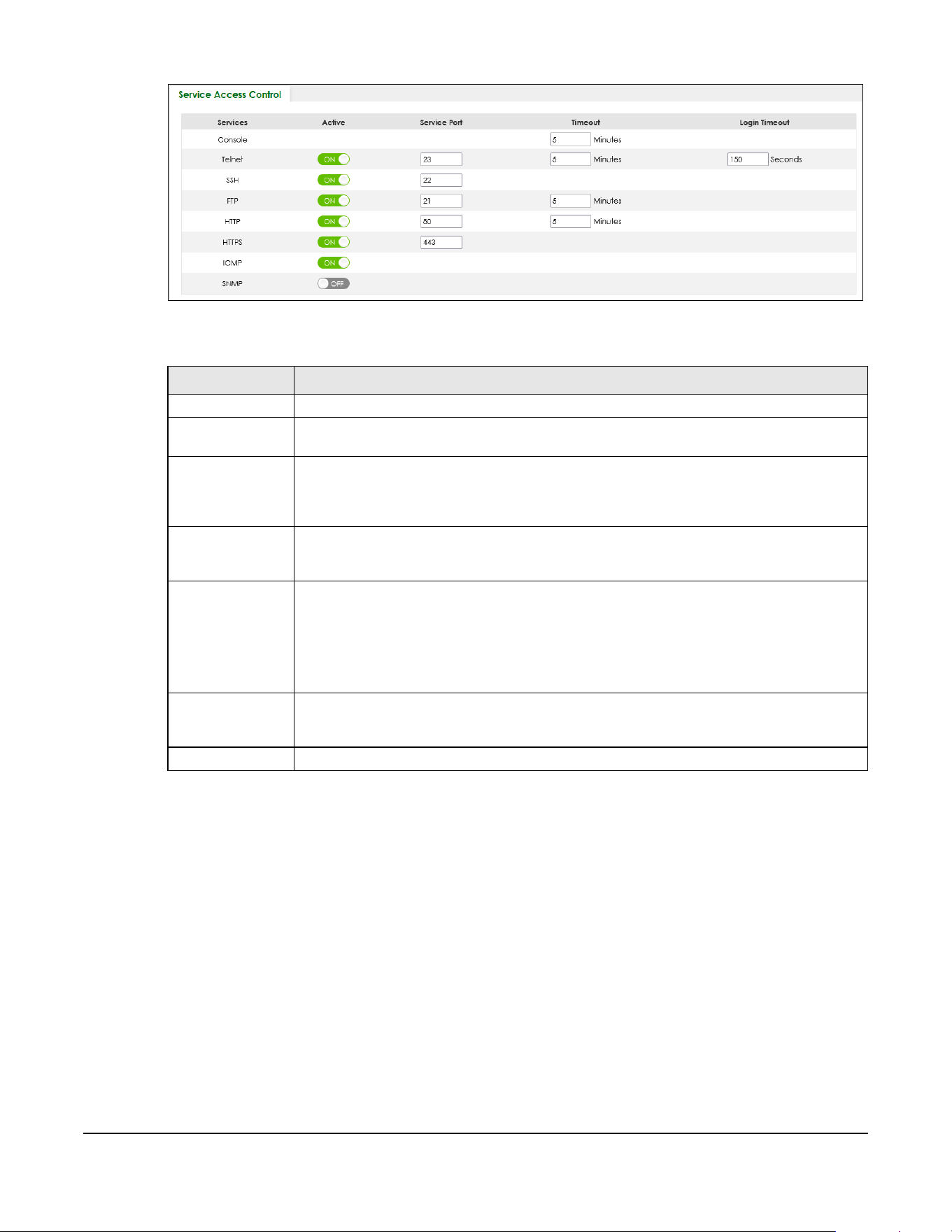
XGS2220 Series User’s Guide
500
Figure 395 SECURITY > Access Control > Service Access Control
The following table describes the fields in this screen.
67.3 Remote Management
Use this screen to specify a group of one or more “trusted computers” from which an administrator may
use a service to manage the Switch.
Click SECURITY > Access Control > Remote Management to view the screen as shown next.
Table 261 SECURITY > Access Control > Service Access Control
LABEL DESCRIPTION
Services Services you may use to access the Switch are listed here.
Active Enable the switch button for the corresponding services that you want to allow to access the
Switch.
Service Port For Telnet, SSH, FTP, HTTP or HTTPS services, you may change the default service port by typing
the new port number in the Service Port field. If you change the default port number then you
will have to let people (who wish to use the service) know the new port number for that
service.
Timeout Enter how many minutes (from 1 to 255) a management session can be left idle before the
session times out. After it times out you have to log in with your password again. Very long idle
timeouts may have security risks.
Login Timeout The Telnet or SSH server do not allow multiple user logins at the same time. Enter how many
seconds (from 30 to 300 seconds) a login session times out. After it times out you have to start
the login session again. Very long login session timeouts may have security risks.
For example, if User A attempts to connect to the Switch (through SSH), but during the login
stage, do not enter the user name and/or password, User B cannot connect to the Switch
(through SSH) before the Login Timeout for User A expires (default 150 seconds).
Apply Click Apply to save your changes to the Switch’s run-time memory. The Switch loses these
changes if it is turned off or loses power, so use the Save link on the top navigation panel to
save your changes to the non-volatile memory when you are done configuring.
Cancel Click Cancel to begin configuring this screen afresh.

Chapter 67 Access Control
XGS2220 Series User’s Guide
501
Figure 396 SECURITY > Access Control > Remote Management
The following table describes the labels in this screen.
67.4 Account Security
Use this screen to encrypt all passwords configured in the Switch. This setting will affect how the
password is shown (as plain text or encrypted text) in the configuration file saved in MAINTENANCE >
Configuration > Save Configuration.
Table 262 SECURITY > Access Control > Remote Management
LABEL DESCRIPTION
Entry This is the client set index number. A “client set” is a group of one or more “trusted computers”
from which an administrator may use a service to manage the Switch.
Active Enable the switch button to activate this secured client set. Clear the check box if you wish to
temporarily disable the set without deleting it.
Start Address
End Address
Configure the IP address range of trusted computers from which you can manage this Switch.
The Switch checks if the client IP address of a computer requesting a service or protocol matches
the range set here. The Switch immediately disconnects the session if it does not match.
Telnet / FTP /
HTTP / ICMP /
SNMP / SSH /
HTTPS
Select services that may be used for managing the Switch from the specified trusted computers.
Apply Click Apply to save your changes to the Switch’s run-time memory. The Switch loses these
changes if it is turned off or loses power, so use the Save link on the top navigation panel to save
your changes to the non-volatile memory when you are done configuring.
Cancel Click Cancel to begin configuring this screen afresh.
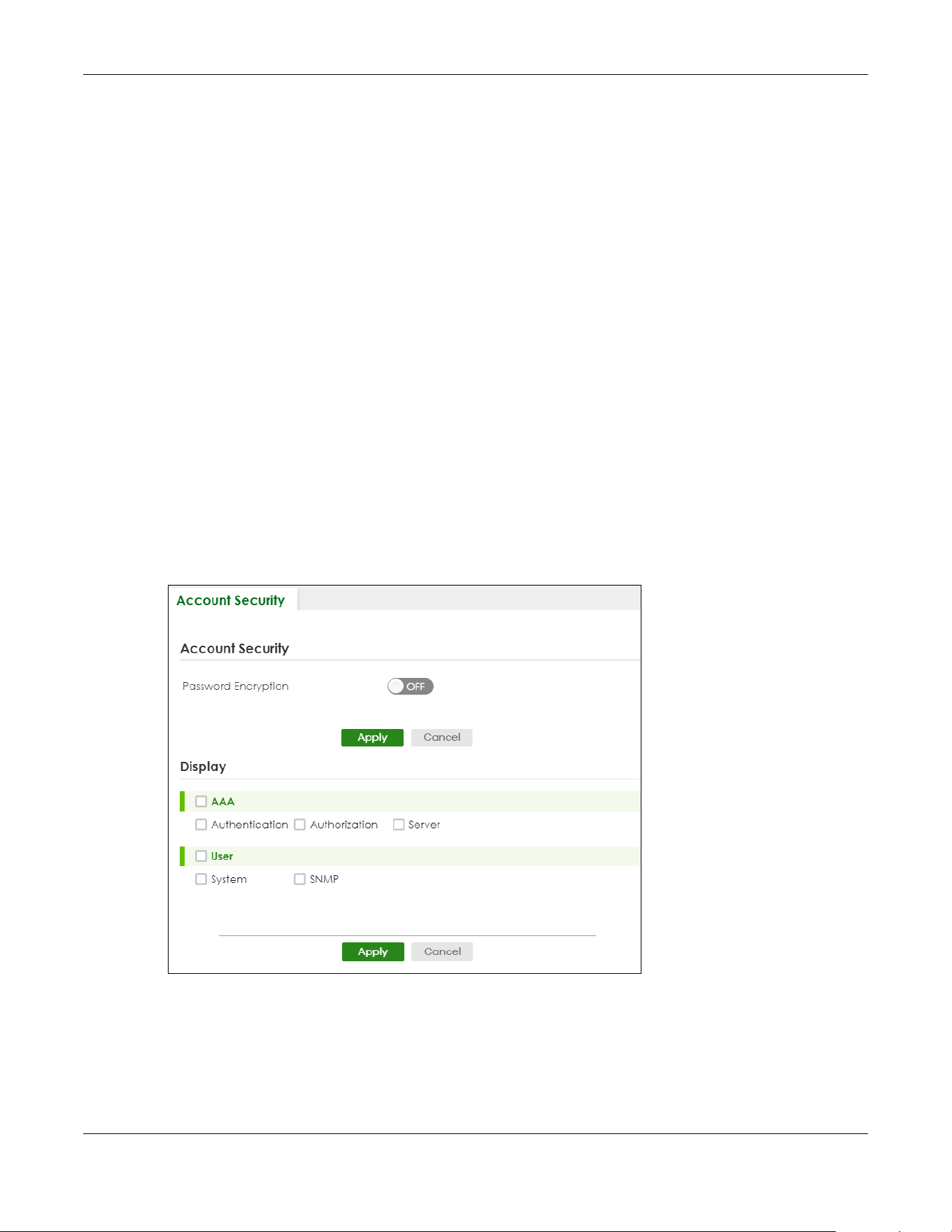
Chapter 67 Access Control
XGS2220 Series User’s Guide
502
Note: Make sure to enable Password Encryption to avoid displaying passwords as plain text in
the configuration file.
Note: Be careful who can access configuration files with plain text passwords!
Password Encryption encrypts all passwords in the configuration file. However, if you want to show some
passwords as plain text in the configuration file, select them as below:
• Authentication information configured for Authentication in the SECURITY > AAA > AAA Setup screen
(Method 1/2/3 setting in the Privilege Enable and Login fields).
• Authorization information configured for Authorization in the SECURITY > AAA > AAA Setup screen
(Active/Console/Method setting in the Exec and Dot1x fields).
• Server information configured for Authentication Server in the SECURITY > AAA > RADIUS Server Setup
screen, and for Authentication Server in the SECURITY > AAA > TACACS+ Server Setup screen (Mode/
Timeout fields).
• System account information configured in the Switch (admin, user login name, and password).
• SNMP user account information configured in the SYSTEM > SNMP > SNMP User screen (password for
SNMP user authentication in the Authentication field, and the password for the encryption method for
SNMP communication in the Privacy field).
Note: The passwords will appear as encrypted text when Password Encryption is Active.
Click SECURITY > Access Control > Account Security to view the screen as shown next.
Figure 397 SECURITY > Access Control > Account Security

Chapter 67 Access Control
XGS2220 Series User’s Guide
503
The following table describes the labels in this screen.
67.5 Technical Reference
This section provides technical background information on the topics discussed in this chapter.
67.5.1 SSH Overview
Unlike Telnet or FTP, which transmit data in clear text, SSH (Secure Shell) is a secure communication
protocol that combines authentication and data encryption to provide secure encrypted
communication between two hosts over an unsecured network.
Figure 398 SSH Communication Example
67.5.1.1 How SSH Works
The following table summarizes how a secure connection is established between two remote hosts.
Table 263 SECURITY > Access Control > Account Security
LABEL DESCRIPTION
Account Security
Password
Encryption
Select this check box to encrypt all passwords configured on the Switch. This displays the
password as encrypted text, in a saved configuration file.
Otherwise, the passwords configured on the Switch are displayed in plain text.
Apply Click Apply to save your changes for Account Security to the Switch’s run-time memory. The
Switch loses these changes if it is turned off or loses power, so use the Save link on the top
navigation panel to save your changes to the non-volatile memory when you are done
configuring.
Cancel Click Cancel to begin configuring Account Security afresh.
Display
AAA Select which specific information to display in plain text, in the saved configuration file.
• Authentication
• Authorization
•Server
User Select which user account information to display in plain text, in the saved configuration file.
•System
•SNMP
Apply Click Apply to save your changes for Display to the Switch’s run-time memory. The Switch loses
these changes if it is turned off or loses power, so use the Save link on the top navigation panel to
save your changes to the non-volatile memory when you are done configuring.
Cancel Click Cancel to begin configuring Display afresh.

Chapter 67 Access Control
XGS2220 Series User’s Guide
504
Figure 399 How SSH Works
1 Host Identification
The SSH client sends a connection request to the SSH server. The server identifies itself with a host key. The
client encrypts a randomly generated session key with the host key and server key and sends the result
back to the server.
The client automatically saves any new server public keys. In subsequent connections, the server public
key is checked against the saved version on the client computer.
2 Encryption Method
Once the identification is verified, both the client and server must agree on the type of encryption
method to use.
3 Authentication and Data Transmission
After the identification is verified and data encryption activated, a secure tunnel is established between
the client and the server. The client then sends its authentication information (user name and password)
to the server to log in to the server.
67.5.1.2 SSH Implementation on the Switch
Your Switch supports SSH version 2 using RSA authentication and three encryption methods (DES, 3DES
and Blowfish). The SSH server is implemented on the Switch for remote management and file transfer on
port 22. Only one SSH connection is allowed at a time.

Chapter 67 Access Control
XGS2220 Series User’s Guide
505
67.5.1.3 Requirements for Using SSH
You must install an SSH client program on a client computer (Windows or Linux operating system) that is
used to connect to the Switch over SSH.
67.5.2 Introduction to HTTPS
HTTPS (HyperText Transfer Protocol over Secure Socket Layer, or HTTP over SSL) is a web protocol that
encrypts and decrypts web pages. Secure Socket Layer (SSL) is an application-level protocol that
enables secure transactions of data by ensuring confidentiality (an unauthorized party cannot read the
transferred data), authentication (one party can identify the other party) and data integrity (you know if
data has been changed).
It relies upon certificates, public keys, and private keys.
HTTPS on the Switch is used so that you may securely access the Switch using the Web Configurator. The
SSL protocol specifies that the SSL server (the Switch) must always authenticate itself to the SSL client (the
computer which requests the HTTPS connection with the Switch), whereas the SSL client only should
authenticate itself when the SSL server requires it to do so. Authenticating client certificates is optional
and if selected means the SSL-client must send the Switch a certificate. You must apply for a certificate
for the browser from a Certificate Authority (CA) that is a trusted CA on the Switch.
Please refer to the following figure.
1 HTTPS connection requests from an SSL-aware web browser go to port 443 (by default) on the Switch’s
WS (web server).
2 HTTP connection requests from a web browser go to port 80 (by default) on the Switch’s WS (web
server).
Figure 400 HTTPS Implementation
Note: If you disable HTTP in the Service Access Control screen, then the Switch blocks all HTTP
connection attempts.
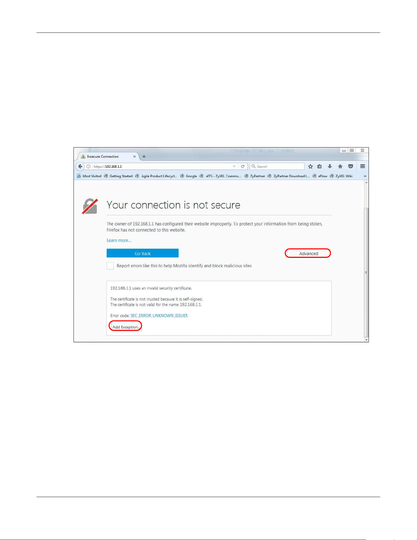
Chapter 67 Access Control
XGS2220 Series User’s Guide
506
67.5.2.1 HTTPS Example
If you have not changed the default HTTPS port on the Switch, then in your browser enter “https://Switch
IP Address/” as the web site address where “Switch IP Address” is the IP address or domain name of the
Switch you wish to access.
Mozilla Firefox Warning Messages
When you attempt to access the Switch HTTPS server, a Your connection is not secure screen may
display. If that is the case, click I Understand the Risks and then the Add Exception... button.
Figure 401 Security Alert (Mozilla Firefox)
Confirm the HTTPS server URL matches. Click Confirm Security Exception to proceed to the Web
Configurator login screen.
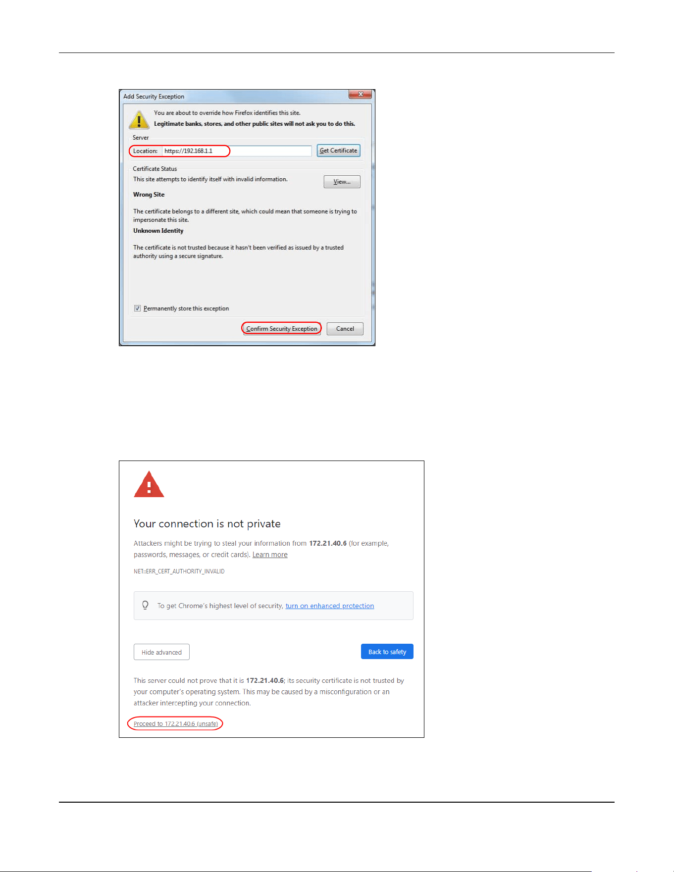
Chapter 67 Access Control
XGS2220 Series User’s Guide
507
Figure 402 Security Alert (Mozilla Firefox)
67.5.3 Google Chrome Warning Messages
When you attempt to access the Switch HTTPS server, a Your connection is not private screen may
display. If that is the case, click Advanced and then Proceed to x.x.x.x (unsafe) to proceed to the Web
Configurator login screen.
Figure 403 Security Alert (Google Chrome 99.0.4844.82)
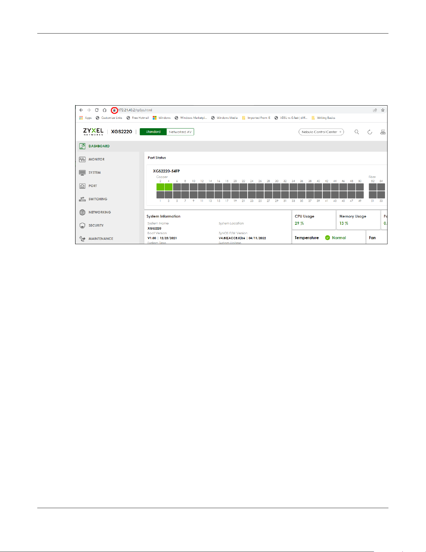
Chapter 67 Access Control
XGS2220 Series User’s Guide
508
67.5.3.1 Main Settings
After you accept the certificate and enter the login user name and password, the Switch main screen
appears. The lock displayed in the bottom right of the browser status bar or next to the website address
denotes a secure connection.
Figure 404 Example: Lock Denoting a Secure Connection

Chapter 68 Classifier
XGS2220 Series User’s Guide
509
CHAPTER 68
Classifier
68.1 Classifier Overview
This chapter introduces and shows you how to configure the packet classifier on the Switch. It also
discusses Quality of Service (QoS) and classifier concepts as employed by the Switch.
68.1.1 What You Can Do
• Use the Classifier Status screen (Section 68.2 on page 510) to view the classifiers configured on the
Switch and how many times the traffic matches the rules.
• Use the Classifier Setup screen (Section 68.3 on page 510) to define the classifiers and view a
summary of the classifier configuration. After you define the classifier, you can specify actions (or
policy) to act upon the traffic that matches the rules.
• Use the Classifier Global Setting screen (Section 68.4 on page 515) to configure the match order and
enable logging on the Switch.
68.1.2 What You Need to Know
Quality of Service (QoS) refers to both a network's ability to deliver data with minimum delay, and the
networking methods used to control the use of bandwidth. Without QoS, all traffic data is equally likely
to be dropped when the network is congested. This can cause a reduction in network performance and
make the network inadequate for time-critical application such as video-on-demand.
A classifier groups traffic into data flows according to specific criteria such as the source address,
destination address, source port number, destination port number or incoming port number. For
example, you can configure a classifier to select traffic from the same protocol port (such as Telnet) to
form a flow.
Configure QoS on the Switch to group and prioritize application traffic and fine-tune network
performance. Setting up QoS involves two separate steps:
1 Configure classifiers to sort traffic into different flows.
2 Configure policy rules to define actions to be performed on a classified traffic flow (refer to Chapter 69
on page 518 to configure policy rules).
You can also configure policy routing to forward a classified traffic flow to a different gateway for cost
savings and load sharing.

Chapter 68 Classifier
XGS2220 Series User’s Guide
510
68.2 Classifier Status
Use this screen to view the classifiers configured on the Switch and how many times the traffic matches
the rules.
Click SECURITY > ACL > Classifier > Classifier Status to display the configuration screen as shown.
Figure 405 SECURITY > ACL > Classifier > Classifier Status
The following table describes the labels in this screen.
68.3 Classifier Setup
Use this screen to view and configure the classifiers. After you define the classifier, you can specify
actions (or policy) to act upon the traffic that matches the rules.
Click SECURITY > ACL > Classifier Setup to display the configuration screen as shown.
Table 264 SECURITY > ACL > Classifier > Classifier Status
LABEL DESCRIPTION
Index This field displays the index number of the rule.
Active This field displays whether the rule is activated or not.
Weight This field displays the rule’s weight. This is to indicate a rule’s priority when the match order is set
to manual in the SECURITY > ACL > Classifier > Classifier Global Setting screen.
The higher the number, the higher the rule’s priority.
Name This field displays the descriptive name for this rule. This is for identification purpose only.
Match Count This field displays the number of times a rule is applied. It displays '–' if the rule does not have
count enabled.
Rule This field displays a summary of the classifier rule’s settings.
Clear the Classifier
Any Select Any, then click Clear to clear the matched count for all classifiers.
Classifier Select Classifier, enter a classifier rule name and then click Clear to erase the recorded
statistical information for that classifier, or select Any to clear statistics for all classifiers.
Clear Click Clear to erase the recorded statistical information for the classifier.

Chapter 68 Classifier
XGS2220 Series User’s Guide
511
Figure 406 SECURITY > ACL > Classifier > Classifier Setup
The following table describes the labels in this screen.
The following table shows some other common Ethernet types and the corresponding protocol number.
In the Internet Protocol there is a field, called “Protocol”, to identify the next level protocol. The following
table shows some common protocol types and the corresponding protocol number. Refer to http://
www.iana.org/assignments/protocol-numbers for a complete list.
Table 265 SECURITY > ACL > Classifier > Classifier Setup
LABEL DESCRIPTION
Index This field displays the index number of the rule.
Active This field displays Yes when the rule is activated and No when it is deactivated.
Weight The field displays the priority of the rule when the match order is in manual mode. A higher weight
means a higher priority.
Name This field displays the descriptive name for this rule. This is for identification purpose only.
Rule This field displays a summary of the classifier rule’s settings.
Select an entry’s check box to select a specific entry. Otherwise, select the check box in the table
heading row to select all entries.
Add/Edit Click Add/Edit to add a new entry or edit a selected one.
Delete Click Delete to remove the selected entries.
Table 266 Common Ethernet Types and Protocol Numbers
ETHERNET TYPE PROTOCOL NUMBER
IP ETHII 0800
X.75 Internet 0801
NBS Internet 0802
ECMA Internet 0803
Chaosnet 0804
X.25 Level 3 0805
XNS Compat 0807
Banyan Systems 0BAD
BBN Simnet 5208
IBM SNA 80D5
AppleTalk AARP 80F3
Table 267 Common IP Protocol Types and Protocol Numbers
PROTOCOL TYPE PROTOCOL NUMBER
ICMP 1
TCP 6
UDP 17
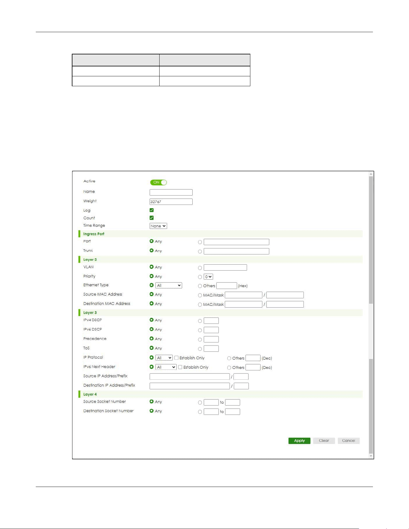
Chapter 68 Classifier
XGS2220 Series User’s Guide
512
68.3.1 Add/Edit a Classifier
Use this screen to define the classifiers. After you define the classifier, you can specify actions (or policy)
to act upon the traffic that matches the rules.
Click Add/Edit, or select an entry and click Add/Edit in the SECURITY > ACL > Classifier Setup screen to
display this screen.
Figure 407 SECURITY > ACL > Classifier > Classifier Setup > Add/Edit
EGP 8
L2TP 115
Table 267 Common IP Protocol Types and Protocol Numbers
PROTOCOL TYPE PROTOCOL NUMBER

Chapter 68 Classifier
XGS2220 Series User’s Guide
513
The following table describes the labels in this screen.
Table 268 SECURITY > ACL > Classifier > Classifier Setup > Add/Edit
LABEL DESCRIPTION
Active Enable the switch button to enable this rule.
Name Enter a descriptive name for this rule for identifying purposes. You can enter up to 32 printable ASCII
characters except [ ? ], [ | ], [ ' ], [ " ] or [ , ].
Weight Enter a number between 0 and 65535 to specify the rule’s weight. When the match order is in manual
mode in the Classifier Global Setting screen, a higher weight means a higher priority.
Log Select this option to have the Switch create a log message when the rule is applied and record the
number of matched packets in a particular time interval.
Note: Make sure you also enable logging in the Classifier Global Setting screen.
Count Select this option to have the Switch count how many times the rule is applied.
Time
Range
Select the name of the pre-configured schedule that you want to apply to the rule. The rule will be
active only at the scheduled date and/or time.
If you select None, the rule will be active all the time.
Ingress Port
Port Type the port number to which the rule should be applied. You may choose one port only or all ports
(Any).
You can enter multiple ports separated by (no space) comma (,) or hyphen (-) for a range. For
example, enter “3-5” for ports 3, 4, and 5. Enter “3,5,7” for ports 3, 5, and 7.
In Stacking mode, the first number represents the slot and the second the port number. Enter 1/1-1/
24,2/23 for ports 1 to 24 for the Switch in slot 1 and port 23 for the Switch in slot 2, for example.
Trunk Select Any to apply the rule to all trunk groups.
Alternatively, to specify multiple trunks, enter the trunk group ID to apply the rule to multiple trunks.
You can enter multiple trunks with (t) or (T) then the trunk group ID separated by (no space) comma
(,) or hyphen (-). For example, enter “t3-t5” for trunks 3, 4, and 5. Enter “T3,T5,T7” for trunks 3, 5, and 7.
Layer 2
Specify the fields below to configure a layer 2 classifier.
VLAN Select Any to classify traffic from any VLAN or select the second option and specify the source VLAN
ID in the field provided.
Priority Select Any to classify traffic from any priority level or select the second option and specify a priority
level in the field provided.
Ethernet
Type
Select an Ethernet type or select Other and enter the Ethernet type number in hexadecimal value.
Source
MAC
Address
Select Any to apply the rule to all MAC addresses.
To specify a source, select MAC/Mask to enter the source MAC address of the packet in valid MAC
address format (six hexadecimal character pairs) and type the mask for the specified MAC address to
determine which bits a packet’s MAC address should match.
Enter “f” for each bit of the specified MAC address that the traffic’s MAC address should match. Enter
“0” for the bits of the matched traffic’s MAC address, which can be of any hexadecimal characters.
For example, if you set the MAC address to 00:13:49:00:00:00 and the mask to ff:ff:ff:00:00:00, a packet
with a MAC address of 00:13:49:12:34:56 matches this criteria. If you leave the Mask field blank, the
Switch automatically sets the mask to ff:ff:ff:ff:ff:ff.

Chapter 68 Classifier
XGS2220 Series User’s Guide
514
Destinatio
n MAC
Address
Select Any to apply the rule to all MAC addresses.
To specify a destination, select MAC/Mask to enter the destination MAC address of the packet in
valid MAC address format (six hexadecimal character pairs) and type the mask for the specified MAC
address to determine which bits a packet’s MAC address should match.
Enter “f” for each bit of the specified MAC address that the traffic’s MAC address should match. Enter
“0” for the bits of the matched traffic’s MAC address, which can be of any hexadecimal characters.
For example, if you set the MAC address to 00:13:49:00:00:00 and the mask to ff:ff:ff:00:00:00, a packet
with a MAC address of 00:13:49:12:34:56 matches this criteria. If you leave the Mask field blank, the
Switch automatically sets the mask to ff:ff:ff:ff:ff:ff.
Layer 3
Specify the fields below to configure a layer 3 classifier.
IPv4/IPv6
DSCP
Select Any to classify traffic from any DSCP or select the second option and specify a DSCP (DiffServ
Code Point) number between 0 and 63 in the field provided.
Preceden
ce
Select Any to classify traffic from any precedence or select the second option and specify an IP
Precedence (the first 3 bits of the 8-bit ToS field) value between 0 and 7 in the field provided.
ToS Select Any to classify traffic from any ToS or select the second option and specify Type of Service (the
last 5 bits of the 8-bit ToS field) value between 0 and 255 in the field provided.
IP Protocol Select an IPv4 protocol type or select Other and enter the protocol number in decimal value.
You may select Establish Only for TCP protocol type. This means that the Switch will pick out the
packets that are sent to establish TCP connections.
IPv6 Next
Header
Select an IPv6 protocol type or select Other and enter an 8-bit next header in the IPv6 packet. The
Next Header field is similar to the IPv4 Protocol field. The IPv6 protocol number ranges from 1 to 255.
You may select Establish Only for TCP protocol type. This means that the Switch will identify packets
that initiate or acknowledge (establish) TCP connections.
Source IP
Address/
Address
Prefix
Enter a source IP address in dotted decimal notation.
Specify the address prefix by entering the number of ones in the subnet mask.
A subnet mask can be represented in a 32-bit notation. For example, the subnet mask “255.255.255.0”
can be represented as “11111111.11111111.11111111.00000000”, and counting up the number of
ones in this case results in 24.
Destinatio
n IP
Address/
Address
Prefix
Enter a destination IP address in dotted decimal notation.
Specify the address prefix by entering the number of ones in the subnet mask.
Layer 4
Specify the fields below to configure a layer 4 classifier.
Source
Socket
Number
Select
Any to apply the rule to all TCP/UDP protocol port numbers or select the second option and
enter a TCP/UDP protocol port number.
Note: You must select either UDP or TCP in the IP Protocol field before you configure the
socket numbers.
Destinatio
n Socket
Number
Select Any to apply the rule to all TCP/UDP protocol port numbers or select the second option and
enter a TCP/UDP protocol port number.
Note: You must select either UDP or TCP in the IP Protocol field before you configure the
socket numbers.
Apply Click Apply to save your changes to the Switch’s run-time memory. The Switch loses these changes if it
is turned off or loses power, so use the Save link on the top navigation panel to save your changes to
the non-volatile memory when you are done configuring.
Table 268 SECURITY > ACL > Classifier > Classifier Setup > Add/Edit (continued)
LABEL DESCRIPTION
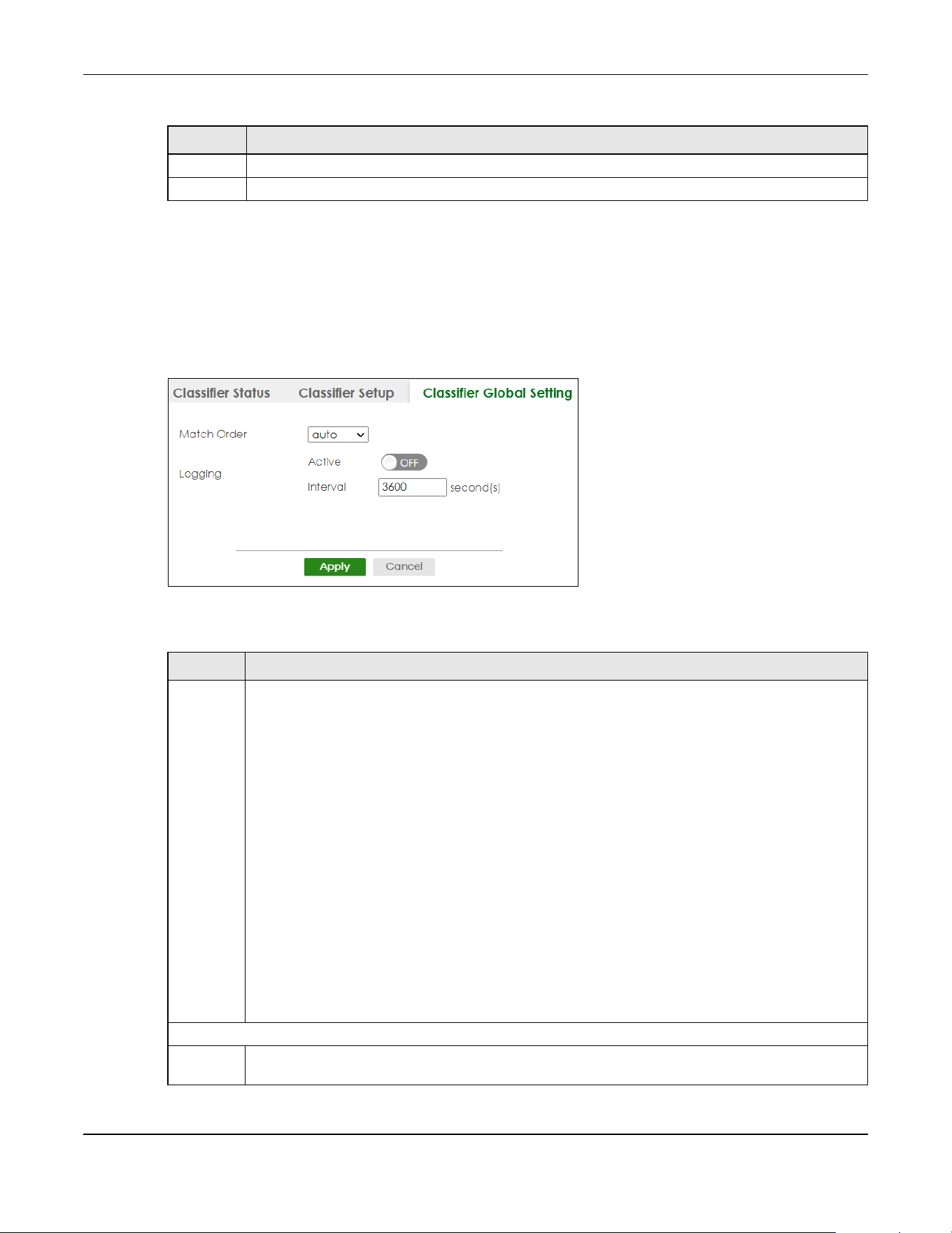
Chapter 68 Classifier
XGS2220 Series User’s Guide
515
68.4 Classifier Global Setting
Use this screen to configure the match order and enable logging on the Switch. Click SECURITY > ACL >
Classifier > Classifier Global Setting to display the configuration screen as shown.
Figure 408 SECURITY > ACL > Classifier > Classifier Global Setting
The following table describes the labels in this screen.
Clear Click Clear to clear the fields to the factory defaults.
Cancel Click Cancel to not save the configuration you make and return to the last screen.
Table 268 SECURITY > ACL > Classifier > Classifier Setup > Add/Edit (continued)
LABEL DESCRIPTION
Table 269 SECURITY > ACL > Classifier > Classifier Global Setting
LABEL DESCRIPTION
Match
Order
Use this field to set the match order for the classifier rules.
A traffic flow can only be classified to one classifier. When a traffic flow matches more than one
classifier rule, the Switch classifies the traffic based on the Match Order.
Select manual to have classifier rules applied according to the weight of each rule you configured in
SECURITY > ACL > Classifier > Classifier Setup. If they have the same weight, the Switch will classify the
traffic to the classifier with a higher name priority (see Classifier Name Priority).
Alternatively, select auto to have classifier rules applied according to the layer of the item configured
in the rule. Layer-4 items have the highest priority, and layer-2 items has the lowest priority. For
example, you configure a layer-2 item (VLAN ID) in classifier A and configure a layer-3 item (source IP
address) in classifier B. When an incoming packet matches both classifier rules, classifier B has priority
over classifier A. If both classifiers have the same priority, the Switch will apply the classifier with a
higher name priority.
Classifier Name Priority
The longer the classifier name, the higher the classifier priority. If two classifier names are the same
length, the bigger the character, the higher the classifier priority. The lowercase letters (such as a and
b) have higher priority than the capitals (such as A and B) in the classifier name. For example, the
classifier with the name of class 2, class a or class B takes priority over the classifier with the name of
class 1 or class A.
Logging
Active Enable the switch button to allow the Switch to create a log when packets match a classifier rule
during a defined time interval.

Chapter 68 Classifier
XGS2220 Series User’s Guide
516
68.5 Classifier Example
The following screen shows an example where you configure a classifier that identifies all traffic from
MAC address 00:50:ba:ad:4f:81 on port 2.
Interval Set the length of the time period (in seconds) to count matched packets for a classifier rule. Enter an
integer from 0 – 65535. 0 means that no logging is done.
Apply Click Apply to save your changes to the Switch’s run-time memory. The Switch loses these changes if it
is turned off or loses power, so use the Save link on the top navigation panel to save your changes to
the non-volatile memory when you are done configuring.
Cancel Click Cancel to begin configuring this screen afresh.
Table 269 SECURITY > ACL > Classifier > Classifier Global Setting (continued)
LABEL DESCRIPTION
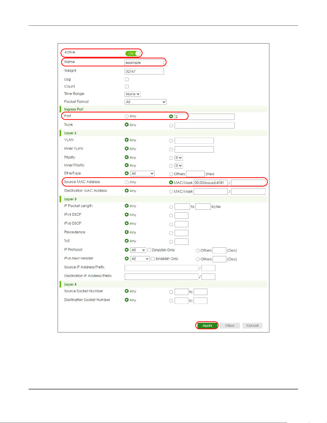
Chapter 68 Classifier
XGS2220 Series User’s Guide
517
Figure 409 Classifier: Example
After you have configured a classifier, you can configure a policy (in the SECURITY > ACL > Policy Rule
screen) to define actions on the classified traffic flow.

Chapter 69 Policy Rule
XGS2220 Series User’s Guide
518
CHAPTER 69
Policy Rule
69.1 Policy Rules Overview
This chapter shows you how to configure policy rules.
A classifier distinguishes traffic into flows based on the configured criteria (refer to Chapter 68 on page
509 for more information). A policy rule ensures that a traffic flow gets the requested treatment in the
network.
69.1.1 What You Can Do
Use the Policy Rule screen (Section 69.2 on page 519) to enable the policy and display the active
classifiers you configure in the Classifier screen.
69.1.2 DiffServ
DiffServ (Differentiated Services) is a class of service (CoS) model that marks packets so that they
receive specific per-hop treatment at DiffServ-compliant network devices along the route based on the
application types and traffic flow. Packets are marked with DiffServ Code Points (DSCPs) indicating the
level of service desired. This allows the intermediary DiffServ-compliant network devices to handle the
packets differently depending on the code points without the need to negotiate paths or remember
state information for every flow. In addition, applications do not have to request a particular service or
give advanced notice of where the traffic is going.
69.1.3 DSCP and Per-Hop Behavior
DiffServ defines a new DS (Differentiated Services) field to replace the Type of Service (TOS) field in the IP
header. The DS field contains a 2-bit unused field and a 6-bit DSCP field which can define up to 64
service levels. The following figure illustrates the DS field.
DSCP is backward compatible with the three precedence bits in the ToS octet so that non-DiffServ
compliant, ToS-enabled network device will not conflict with the DSCP mapping.
The DSCP value determines the forwarding behavior, the PHB (Per-Hop Behavior), that each packet
gets across the DiffServ network. Based on the marking rule, different kinds of traffic can be marked for
different kinds of forwarding. Resources can then be allocated according to the DSCP values and the
configured policies.
DSCP (6 bits) Unused (2 bits)
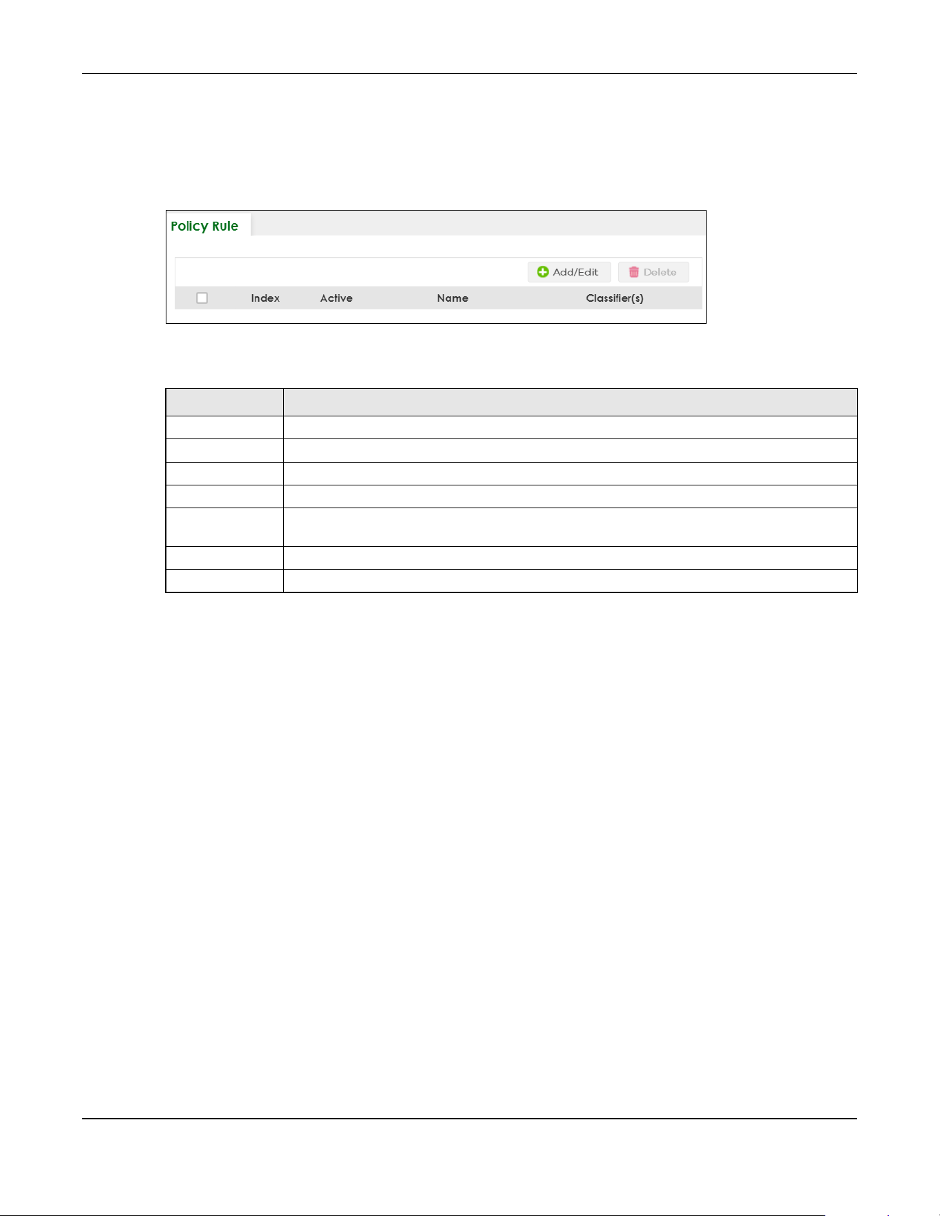
Chapter 69 Policy Rule
XGS2220 Series User’s Guide
519
69.2 Policy Rules
Click SECURITY > ACL > Policy Rule in the navigation panel to display the screen as shown.
Figure 410 SECURITY > ACL > Policy Rule
The following table describes the labels in this screen.
69.2.1 Add/Edit a Policy Rule
You must first configure a classifier in the SECURITY > ACL > Classifier > Classifier Setup screen.
Click Add/Edit, or select an entry and click Add/Edit in the SECURITY > ACL > Policy Rule screen to
display this screen.
Table 270 SECURITY > ACL > Policy Rule
LABEL DESCRIPTION
Index This field displays the policy index number.
Active This field displays whether policy is activated or not.
Name This field displays the name you have assigned to this policy.
Classifier(s) This field displays the names of the classifier to which this policy applies.
Select an entry’s check box to select a specific entry. Otherwise, select the check box in the
table heading row to select all entries.
Add/Edit Click Add/Edit to add a new entry or edit a selected one.
Delete Click Delete to remove the selected entries.
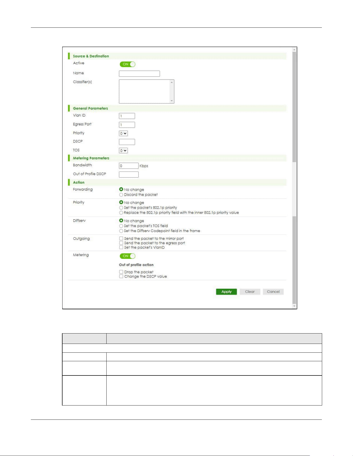
Chapter 69 Policy Rule
XGS2220 Series User’s Guide
520
Figure 411 SECURITY > ACL > Policy Rule > Add/Edit
The following table describes the labels in this screen.
Table 271 SECURITY > ACL > Policy Rule > Add/Edit
LABEL DESCRIPTION
Source & Destination
Active Enable the switch button to enable the policy.
Name Enter a descriptive name for identification purposes. You can enter up to 32 printable ASCII
characters except [ ? ], [ | ], [ ' ], [ " ] or [ , ].
Classifier(s) This field displays the active classifiers you configure in the SECURITY > ACL > Classifier >
Classifier Setup screen.
Select the classifiers to which this policy rule applies. To select more than one classifier, press
[SHIFT] and select the choices at the same time.
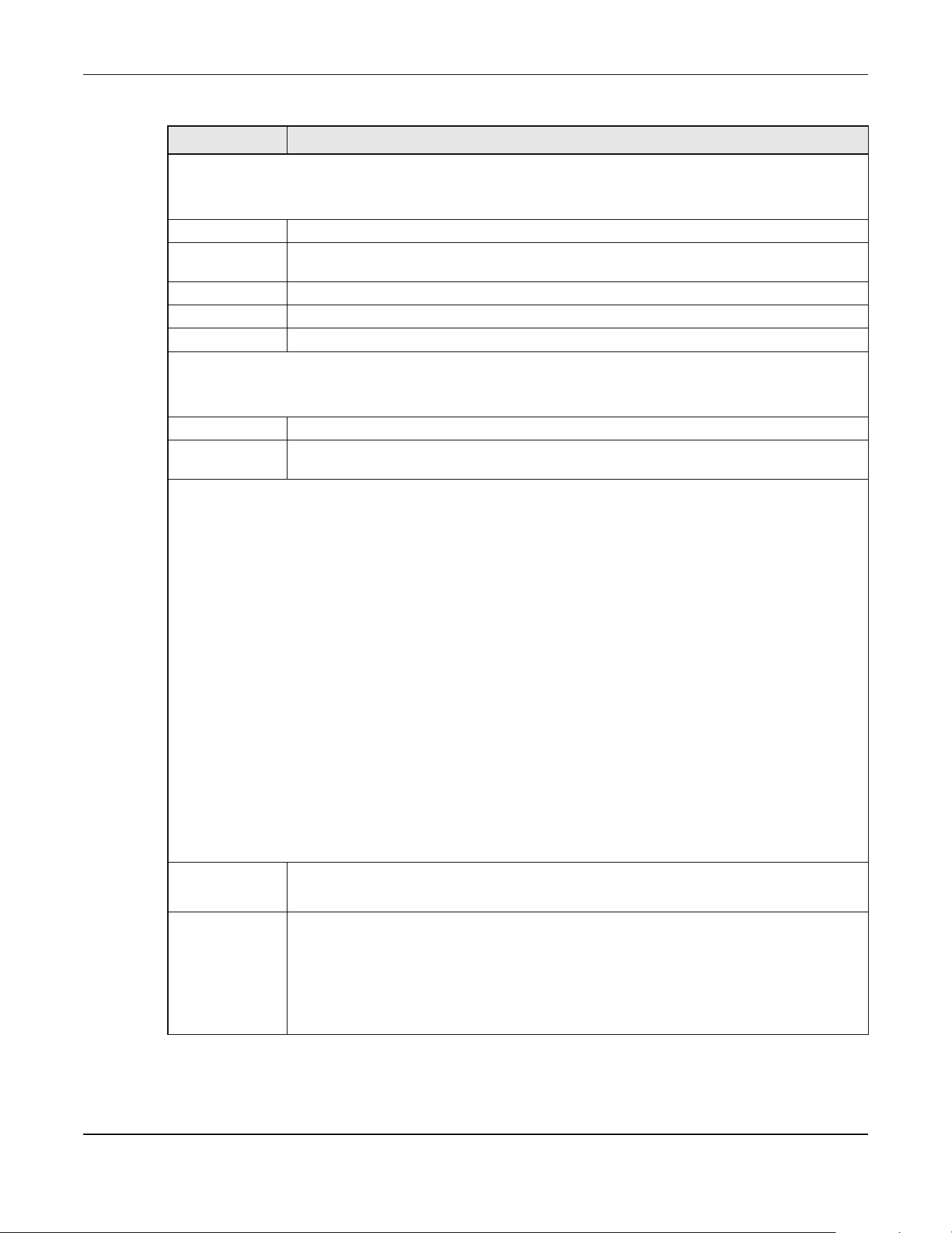
Chapter 69 Policy Rule
XGS2220 Series User’s Guide
521
General Parameters
Set the fields below for this policy. You only have to set the fields that is related to the actions you configure in the
Action field.
Vlan ID Specify a VLAN ID.
Egress Port Enter the number of an outgoing port. In stacking mode, the first number represents the slot
and the second the port number.
Priority Specify a priority level.
DSCP Specify a DSCP (DiffServ Code Point) number between 0 and 63.
TOS Specify the Type Of Service (TOS) priority level.
Metering Parameters
You can configure the desired bandwidth available to a traffic flow. Traffic that exceeds the maximum bandwidth
allocated (in cases where the network is congested) is called out-of-profile traffic.
Bandwidth Specify the bandwidth in kilobit per second (Kbps). Enter a number between 1 and 1000000.
Out of Profile
DSCP
Specify a new DSCP number (between 0 and 63) if you want to replace or remark the DSCP
number for out-of-profile traffic.
Action
Specify the actions the Switch takes on the associated classified traffic flow.
Note: You can specify only one action (option) for each category (Forwarding, Priority, Queue,
Diffserv, Outgoing, Metering) in a policy rule.
Note: The Switch only applies one policy rule for each traffic flow.
Say you have a traffic flow that matches several classifiers, and you specify a different policy rule for each. The
Switch only classifies the traffic flow to the classifier with the highest Match Order. The Switch then applies the policy
rule with which the classifier is associated. You can set the classifier Match Order rule (manual or auto) in the ACL >
Classfier > Classifier Global settings screen (see Section 68.4 on page 515 for more information).
Let’s say you set two classifiers (Class 1 and Class 2) and both identify all traffic from MAC address 11:22:33:44:55:66
on port 3.
If Policy 1 applies to Class 1 and the action is to drop the packets, Policy 2 applies to Class 2 and the action is to
forward the packets to the egress port, the Switch will forward the packets.
If Policy 1 applies to Class 1 and the action is to drop the packets, Policy 2 applies to Class 2 and the action is to
enable bandwidth limitation, the Switch will discard the packets immediately.
If Policy 1 applies to Class 1 and the action is to forward the packets to the egress port, Policy 2 applies to Class 2
and the action is to enable bandwidth limitation, the Switch will forward the packets.
Forwarding Select No change to forward the packets.
Select Discard the packet to drop the packets.
Priority Select No change to keep the priority setting of the frames.
Select Set the packet’s 802.1p priority to replace the packet’s 802.1p priority field with the
value you set in the Priority field and put the packets in the designated queue.
Select Replace the 802.1p priority field with the inner 802.1p priority value to replace the
packet’s 802.1p priority field with the existing customer priority level carried in the frames and
put the packets in the designated queue.
Table 271 SECURITY > ACL > Policy Rule > Add/Edit (continued)
LABEL DESCRIPTION
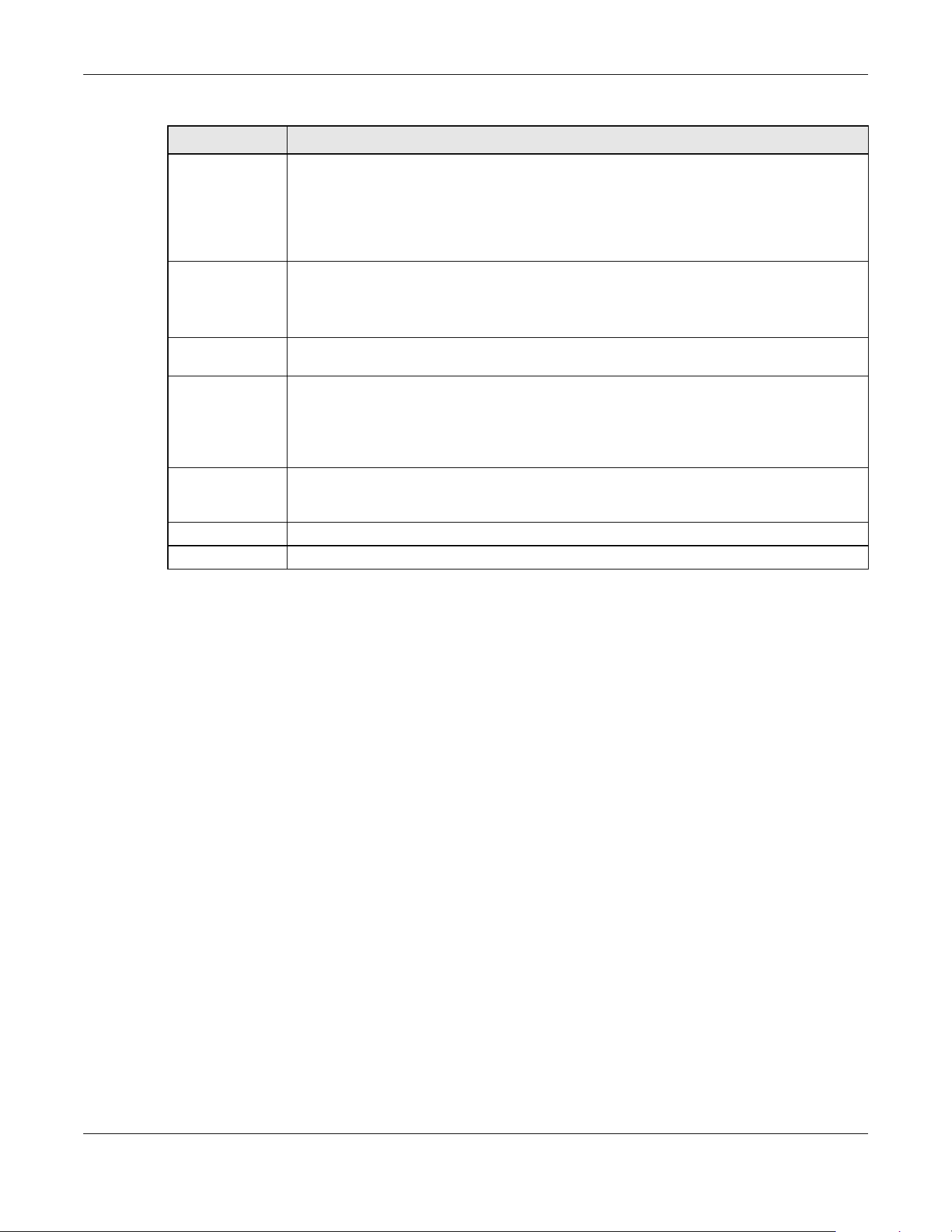
Chapter 69 Policy Rule
XGS2220 Series User’s Guide
522
69.3 Policy Example
The figure below shows an example SECURITY > ACL > Policy Rule screen where you configure a policy
to limit bandwidth and discard out-of-profile traffic on a traffic flow classified using the Example classifier
(refer to Section 68.5 on page 516).
Diffserv Select No change to keep the TOS and/or DSCP fields in the packets.
Select Set the packet’s TOS field to set the TOS field with the value you configure in the TOS
field.
Select Set the Diffserv Codepoint field in the frame to set the DSCP field with the value you
configure in the DSCP field.
Outgoing Select Send the packet to the mirror port to send the packet to the mirror port.
Select Send the packet to the egress port to send the packet to the egress port.
Select Set the packet's VLAN ID to set the packet’s VLAN ID.
Metering Enable the switch button to activate bandwidth limitation on the traffic flows then set the
actions to be taken on out-of-profile packets.
Out of profile
action
Select the actions to be performed for out-of-profile traffic.
Select Drop the packet to discard the out-of-profile traffic.
Select Change the DSCP value to replace the DSCP field with the value specified in the Out of
profile DSCP field.
Apply Click Apply to save your changes to the Switch’s run-time memory. The Switch loses these
changes if it is turned off or loses power, so use the Save link on the top navigation panel to
save your changes to the non-volatile memory when you are done configuring.
Clear Click Clear to clear the fields to the factory defaults.
Cancel Click Cancel to not save the configuration you make and return to the last screen.
Table 271 SECURITY > ACL > Policy Rule > Add/Edit (continued)
LABEL DESCRIPTION
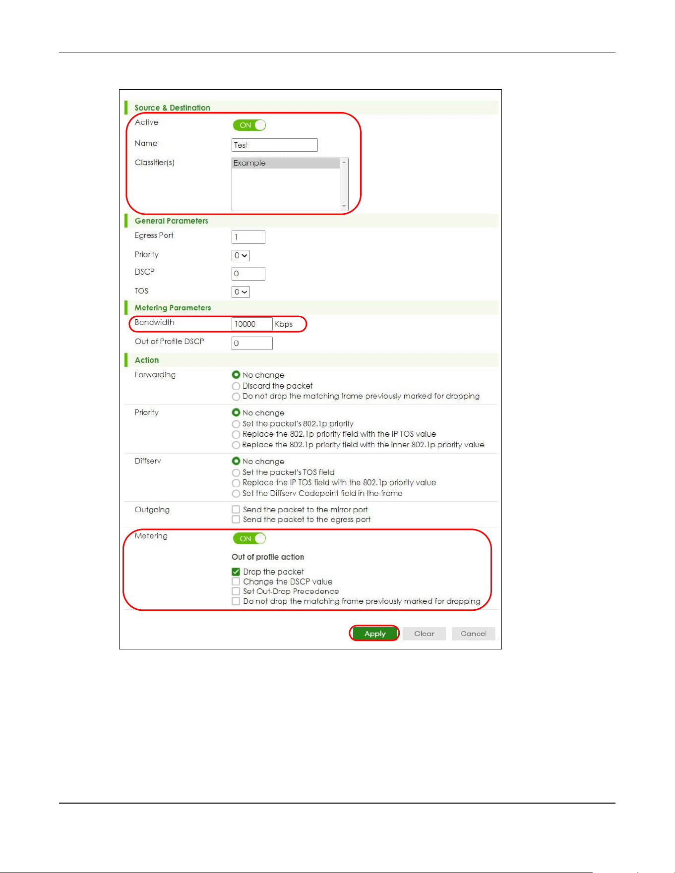
Chapter 69 Policy Rule
XGS2220 Series User’s Guide
523
Figure 412 Policy Example

Chapter 70 Anti-Arpscan
XGS2220 Series User’s Guide
524
CHAPTER 70
Anti-Arpscan
70.1 Anti-Arpscan Overview
Address Resolution Protocol (ARP), RFC 826, is a protocol used to convert a network-layer IP address to a
link-layer MAC address. ARP scan is used to scan the network of a certain interface for alive hosts. It
shows the IP address and MAC addresses of all hosts found. Hackers could use ARP scan to find targets
in your network. Anti-arpscan is used to detect unusual ARP scan activity and block suspicious hosts or
ports.
Unusual ARP scan activity is determined by port and host thresholds that you set. A port threshold is
determined by the number of packets received per second on the port. If the received packet rate is
over the threshold, then the port is put into an Err-Disable state. You can recover the normal state of the
port manually if this happens and after you identify the cause of the problem.
A host threshold is determined by the number of ARP-request packets received per second. There is a
global threshold rate for all hosts. If the rate of a host is over the threshold, then that host is blocked by
using a MAC address filter. A blocked host is released automatically after the MAC aging time expires.
Note: A port-based threshold must be larger than the host-based threshold or the host-based
threshold will not work.
70.1.1 What You Can Do
• Use the Anti-Arpscan Status screen (Section 70.2 on page 525) to see what ports are trusted and are
forwarding traffic or are disabled.
• Use the Anti-Arpscan Host Status screen (Section 70.3 on page 526) to view blocked hosts and clear
selected ones.
• Use this Anti-Arpscan Setup screen (Section 70.4 on page 527) to enable anti-arpscan, set port and
host thresholds as well as configure ports to be trusted or untrusted.
• Use the Anti-Arpscan Trust Host screen (Section 70.5 on page 529) to create or remove trusted hosts
identified by IP address and subnet mask. Anti-arpscan is not performed on trusted hosts.
70.1.2 What You Need to Know
• You should set an uplink port as a trusted port before enabling Anti-arpscan so as to prevent the port
from being shutdown due to receiving too many ARP messages.
• When a port is configured as a trusted port, Anti-arpscan is not performed on the port. Both host and
port thresholds are ignored for trusted ports. If the received ARP packet rate on a port or the received
ARP-requests from a host exceed the thresholds, the trusted port will not be closed.
• If a port on the Switch is closed by Anti-arpscan, and you want to recover it, then do one of the
following:
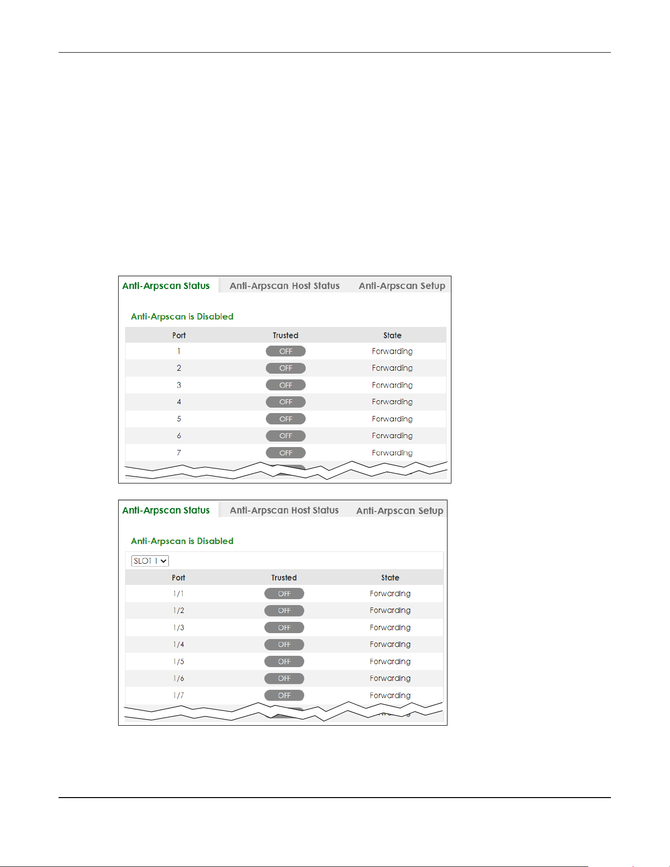
Chapter 70 Anti-Arpscan
XGS2220 Series User’s Guide
525
•Go to PORT > Port Setup. Clear Active and click Apply. Then select Active and click Apply again.
•Go to SECURITY > Errdisable > Errdisable Recovery and set the interval for anti-arpscan. After the
interval expires, the closed ports will become active and start receiving packets again.
• Use the command port no inactive.
• Refer to the port logs to see when a port was closed.
70.2 Anti-Arpscan Status
Use this screen to see what ports are trusted and are forwarding traffic or are disabled. To open this
screen, click SECURITY > Anti-Arpscan > Anti-Arpscan Status.
Figure 413 SECURITY > Anti-Arpscan > Anti-Arpscan Status (Standalone Mode)
Figure 414 SECURITY > Anti-Arpscan > Anti-Arpscan Status (Stacking Mode)
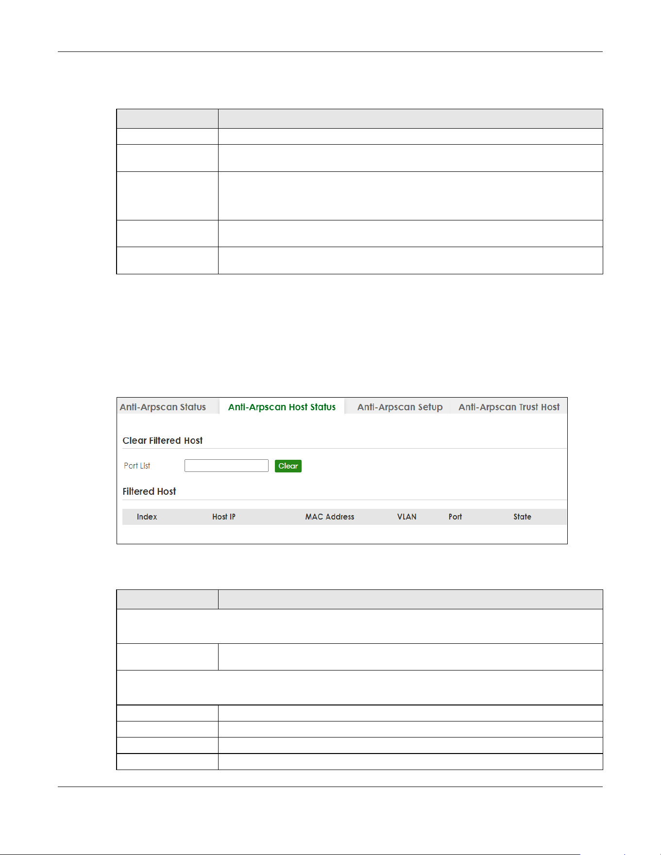
Chapter 70 Anti-Arpscan
XGS2220 Series User’s Guide
526
The following table describes the fields in this screen.
70.3 Anti-Arpscan Host Status
Use this screen to view blocked hosts and unblock ones connected to certain ports. To open this screen,
click SECURITY > Anti-Arpscan > Anti-Arpscan Host Status.
Figure 415 SECURITY > Anti-Arpscan > Anti-Arpscan Host Status
The following table describes the fields in the above screen.
Table 272 SECURITY > Anti-Arpscan > Anti-Arpscan Status
LABEL DESCRIPTION
Anti-Arpscan is.... This shows whether Anti-arpscan is enabled or disabled on the Switch.
SLOT This field appears only in Stacking mode. Click the drop-down list to choose the slot
number of the Switch in a stack.
Port This field displays the port number of the Switch. In Stacking mode, the first number
represents the slot ID and the second is the port number. Please note that the default
stacking ports (the last four ports of your Switch) cannot be configured. They are reserved
for stacking only.
Trusted This field displays whether the port is trusted or untrusted. Anti-arpscan is not performed on
a trusted port.
State This field displays whether the port can forward traffic normally (Forwarding) or is disabled
(Err-Disable).
Table 273 SECURITY > Anti-Arpscan > Anti-Arpscan Host Status
LABEL DESCRIPTION
Clear Filtered host
A filtered host is a blocked IP address.
Port List Enter a port number or a series of port numbers separated by commas and spaces, and
then click Clear to unblock all hosts connected to these ports.
Filtered host
This table lists information on blocked hosts.
Index This displays the index number of an IP address (a host) that has been blocked.
Host IP This displays the IP address of the blocked host.
MAC Address This displays the MAC address of the blocked host.
VLAN This displays the VLAN ID that shows which VLAN the blocked host is in.

Chapter 70 Anti-Arpscan
XGS2220 Series User’s Guide
527
70.4 Anti-Arpscan Setup
Use this screen to enable Anti-Arpscan, set port and host thresholds as well as configure ports to be
trusted or untrusted. To open this screen, click SECURITY > Anti-Arpscan > Anti-Arpscan Setup.
Figure 416 SECURITY > Anti-Arpscan > Anti-Arpscan Setup (Standalone Mode)
Port This displays the port number to which the blocked host is connected.
State This shows Err-Disable if the ARP-request rate from this host is over the threshold. Forwarding
hosts are not displayed.
Table 273 SECURITY > Anti-Arpscan > Anti-Arpscan Host Status (continued)
LABEL DESCRIPTION
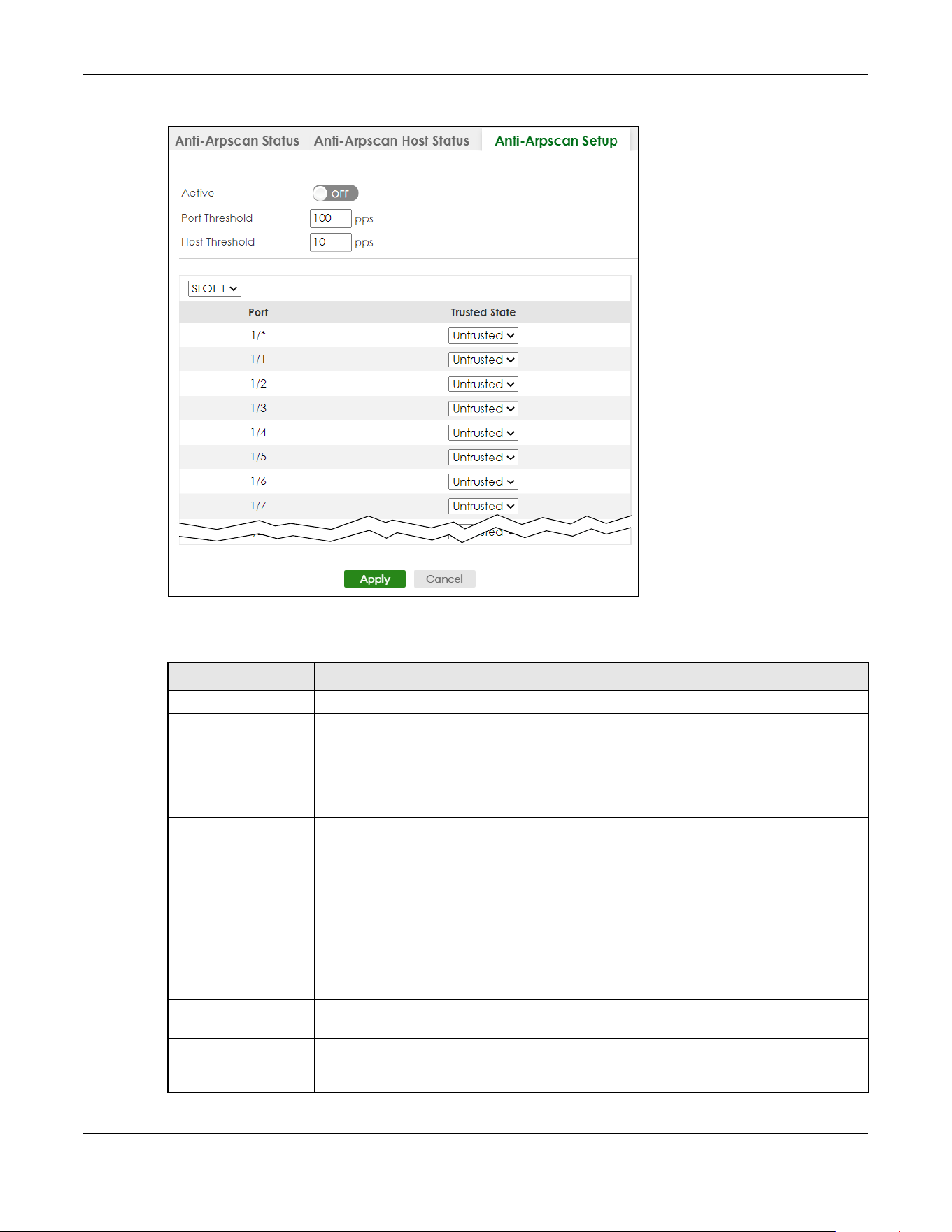
Chapter 70 Anti-Arpscan
XGS2220 Series User’s Guide
528
Figure 417 SECURITY > Anti-Arpscan > Anti-Arpscan Setup (Stacking Mode)
The following table describes the fields in the above screen.
Table 274 SECURITY > Anti-Arpscan > Anti-Arpscan Setup
LABEL DESCRIPTION
Active Enable the switch button to enable Anti-arpscan on the Switch.
Port Threshold A port threshold is determined by the number of packets received per second on the port.
If the received packet rate is over the threshold, then the port is put into an Err-Disable
state. Type the maximum number of packets per second allowed on the port before it is
blocked.
Note: The allowed range is 2 to 255 packets received per second.
Host Threshold A host threshold is determined by the number of ARP-request packets received per
second. This is the global threshold rate for all hosts. If the rate of a host is over the
threshold, then that host is blocked by using a MAC address filter. A blocked host is
released automatically after the MAC aging time expires.
Type the maximum number of ARP-request packets allowed by a host before it is blocked.
Note: The allowed range is 2 to 100 ARP-request packets per second.
Note: The port-based threshold must be larger than the host-based threshold or
the host-based threshold will not be applied.
SLOT This field appears only in Stacking mode. Click the drop-down list to choose the slot
number of the Switch in a stack.
Port This field displays the port number. In Stacking mode, the first number represents the slot ID
and the second is the port number. Please note that the default stacking ports (the last
four ports of your Switch) cannot be configured. They are reserved for stacking only.

Chapter 70 Anti-Arpscan
XGS2220 Series User’s Guide
529
70.5 Anti-Arpscan Trust Host
Use this screen to create or remove trusted hosts identified by IP address and subnet mask. Anti-arpscan
is not performed on trusted hosts. To open this screen, click SECURITY > Anti-Arpscan > Anti-Arpscan Trust
Host.
Figure 418 SECURITY > Anti-Arpscan > Anti-Arpscan Trust Host
The following table describes the fields in the above screen.
70.5.1 Add/Edit Anti-Arpscan Trust Hosts
Use this screen to add/edit trusted hosts identified by IP address and subnet mask. Click Add/Edit, or
select an entry and click Add/Edit in the SECURITY > Anti-Arpscan > Anti-Arpscan Trust Host screen to
view this screen.
* Settings in this row apply to all ports.
Use this row only if you want to make some settings the same for all ports. Use this row first to
set the common settings and then make adjustments on a port-by-port basis.
Note: Changes in this row are copied to all the ports as soon as you make them.
Trusted State Select Untrusted or Trusted for the associated port. Anti-arpscan is not performed on
trusted hosts.
Apply Click Apply to save your changes to the Switch’s run-time memory. The Switch loses these
changes if it is turned off or loses power, so use the Save link on the top navigation panel to
save your changes to the non-volatile memory when you are done configuring.
Cancel Click this to reset the values in this screen to their last-saved values.
Table 274 SECURITY > Anti-Arpscan > Anti-Arpscan Setup (continued)
LABEL DESCRIPTION
Table 275 SECURITY > Anti-Arpscan > Anti-Arpscan Trust Host
LABEL DESCRIPTION
Index This field displays a sequential number for each trusted host.
Name This field displays the name of the trusted host.
Host IP This field displays the IP address of the trusted host.
Mask This field displays the subnet mask of the trusted host.
Select an entry’s check box to select a specific entry. Otherwise, select the check box in
the table heading row to select all entries.
Add/Edit Click Add/Edit to add a new entry or edit a selected one.
Delete Click Delete to remove the selected entries.
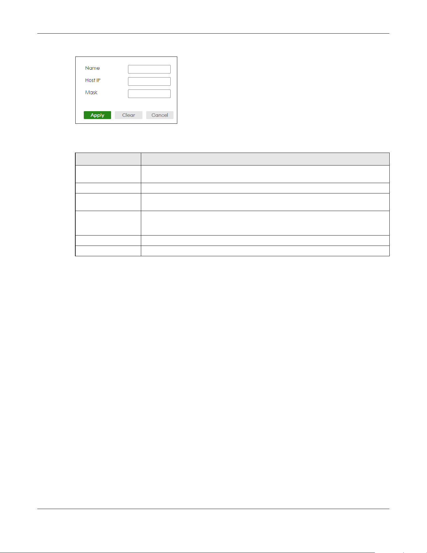
Chapter 70 Anti-Arpscan
XGS2220 Series User’s Guide
530
Figure 419 SECURITY > Anti-Arpscan > Anti-Arpscan Trust Host > Add/Edit
The following table describes the fields in the above screen.
Table 276 SECURITY > Anti-Arpscan > Anti-Arpscan Trust Host > Add/Edit
LABEL DESCRIPTION
Name Type a descriptive name of up to 32 printable ASCII (except [ ? ], [ | ], [ ' ], [ " ] or [ , ])
characters to identify this host.
Host IP Type the IP address of the host.
Mask A trusted host may consist of a subnet of IP addresses. Type a subnet mask to create a
single host or a subnet of hosts.
Apply Click Apply to save your changes to the Switch’s run-time memory. The Switch loses these
changes if it is turned off or loses power, so use the Save link on the top navigation panel to
save your changes to the non-volatile memory when you are done configuring.
Clear Click Clear to clear the fields to the factory defaults.
Cancel Click Cancel to not save the configuration you make and return to the last screen.
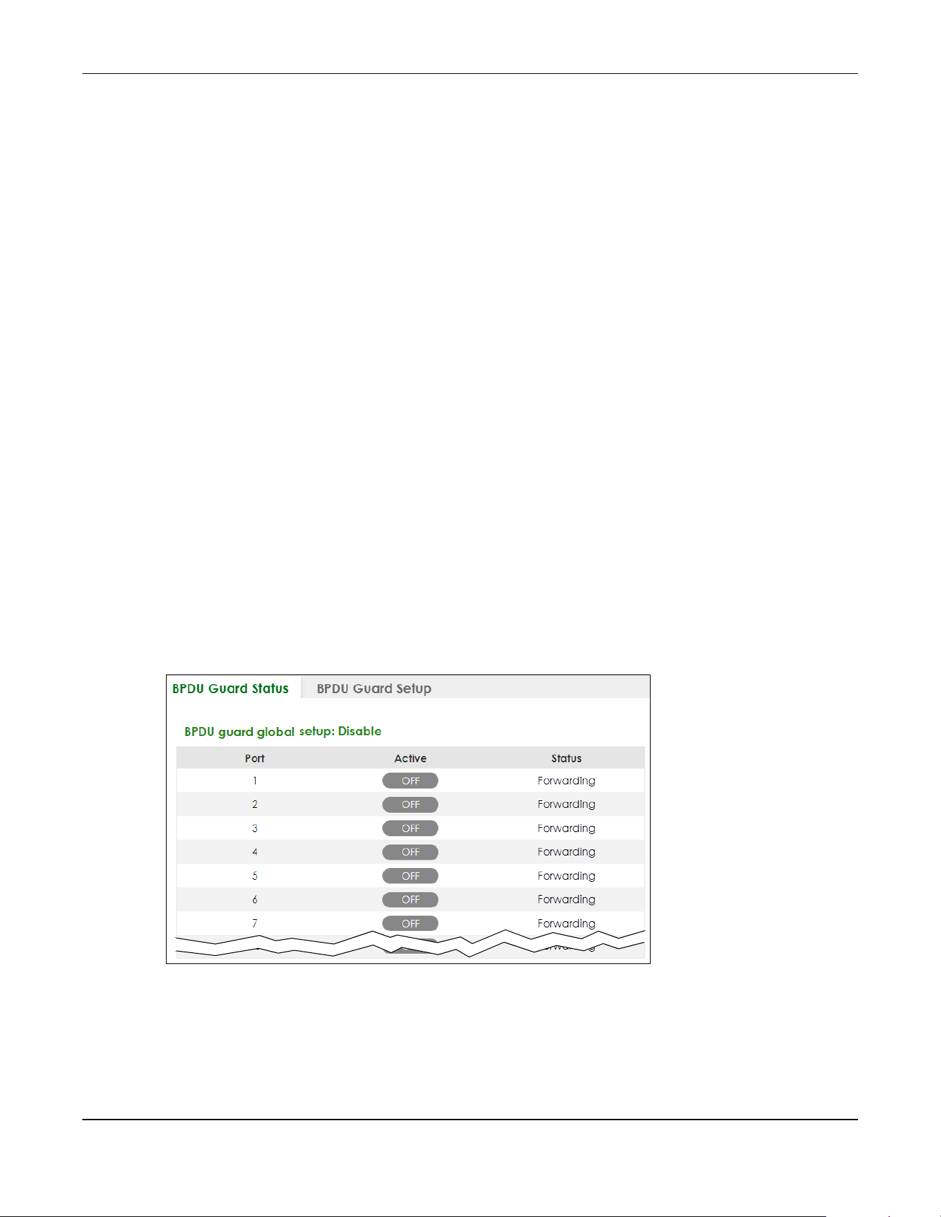
Chapter 71 BPDU Guard
XGS2220 Series User’s Guide
531
CHAPTER 71
BPDU Guard
71.1 BPDU Guard Overview
A BPDU (Bridge Protocol Data Units) is a data frame that contains information about STP. STP-aware
switches exchange BPDUs periodically.
The BPDU guard feature allows you to prevent any new STP-aware switch from connecting to an existing
network and causing STP topology changes in the network. If there is any BPDU detected on the ports
on which BPDU guard is enabled, the Switch disables the ports automatically. You can then enable the
ports manually in the PORT > Port Setup screen, or use the SECURITY > Errdisable > Errdisable Recovery
screen (see Section 73.5 on page 544) to have the ports become active after a certain time interval.
71.2 BPDU Guard Status
Use this screen to view whether BPDU guard is enabled on the Switch and the port status. Click SECURITY
> BPDU Guard > BPDU Guard Status to view the following screen.
Figure 420 SECURITY > BPDU Guard > BPDU Guard Status (Standalone Mode)

Chapter 71 BPDU Guard
XGS2220 Series User’s Guide
532
Figure 421 SECURITY > BPDU Guard > BPDU Guard Status (Stacking Mode)
The following table describes the fields in the above screen.
71.3 BPDU Guard Setup
Use this screen to turn on the BPDU guard feature on the Switch and ports.
Click SECURITY > BPDU Guard > BPDU Guard Setup to display the configuration screen as shown.
Table 277 SECURITY > BPDU Guard > BPDU Guard Status
LABEL DESCRIPTION
BPDU guard global
setup
This field displays whether BPDU guard is activated on the Switch.
SLOT This field appears only in Stacking mode. Click the drop-down list to choose the slot
number of the Switch in a stack.
Port This field displays the port number. In Stacking mode, the first number represents the slot ID
and the second is the port number. Please note that the default stacking ports (the last
four ports of your Switch) cannot be configured. They are reserved for stacking only.
Active This shows whether BPDU guard is activated on the port.
Status This shows whether the port is shut down (Err-disable) or able to transmit packets
(Forwarding).
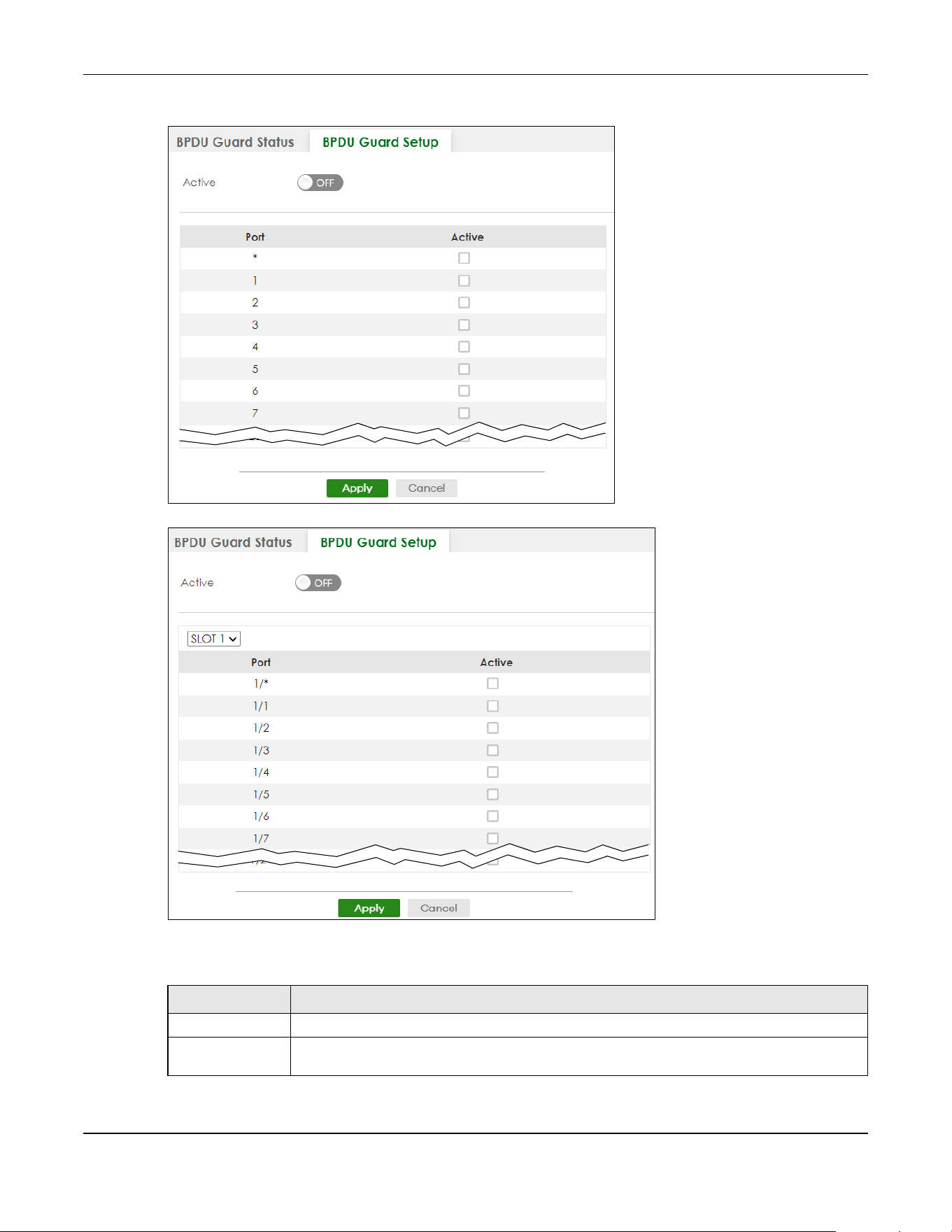
Chapter 71 BPDU Guard
XGS2220 Series User’s Guide
533
Figure 422 SECURITY > BPDU Guard > BPDU Guard Setup (Standalone Mode)
Figure 423 SECURITY > BPDU Guard > BPDU Guard Setup (Stacking Mode)
The following table describes the fields in the above screen.
Table 278 SECURITY > BPDU Guard > BPDU Guard Setup
LABEL DESCRIPTION
Active Enable the switch button to enable BPDU guard on the Switch.
SLOT This field appears only in Stacking mode. Click the drop-down list to choose the slot number of
the Switch in a stack.
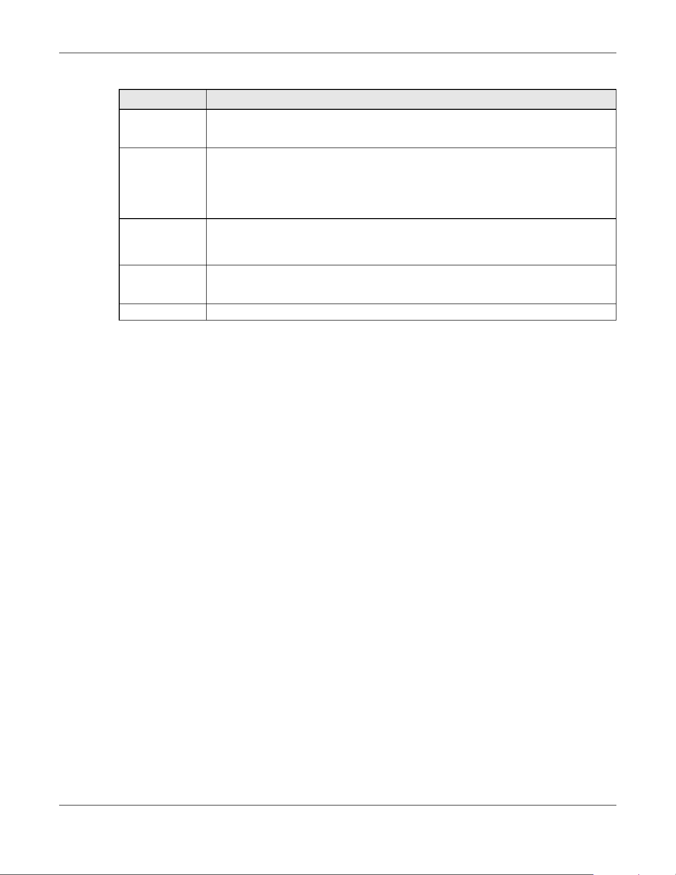
Chapter 71 BPDU Guard
XGS2220 Series User’s Guide
534
Port This field displays the port number. In Stacking mode, the first number represents the slot ID and
the second is the port number. Please note that the default stacking ports (the last four ports of
your Switch) cannot be configured. They are reserved for stacking only.
* Settings in this row apply to all ports.
Use this row only if you want to make some settings the same for all ports. Use this row first to set
the common settings and then make adjustments on a port-by-port basis.
Note: Changes in this row are copied to all the ports as soon as you make them.
Active Select this check box to enable the BPDU guard feature on this port. The Switch shuts down this
port if there is any BPDU received on the port.
Clear this check box to disable the BPDU guard feature.
Apply Click Apply to save your changes to the Switch’s run-time memory. The Switch loses these
changes if it is turned off or loses power, so use the Save link on the top navigation panel to
save your changes to the non-volatile memory when you are done configuring.
Cancel Click Cancel to begin configuring this screen afresh.
Table 278 SECURITY > BPDU Guard > BPDU Guard Setup (continued)
LABEL DESCRIPTION

Chapter 72 Storm Control
XGS2220 Series User’s Guide
535
CHAPTER 72
Storm Control
72.1 Storm Control Overview
This chapter introduces and shows you how to configure the storm control feature.
Storm control limits the number of broadcast, multicast and destination lookup failure (DLF) packets the
Switch receives per second on the ports. When the maximum number of allowable broadcast, multicast
and/or DLF packets is reached per second, the subsequent packets are discarded. Enable this feature
to reduce broadcast, multicast and/or DLF packets in your network. You can specify limits for each
packet type on each port.
72.1.1 What You Can Do
Use the Storm Control screen (Section 72.2 on page 535) to limit the number of broadcast, multicast and
destination lookup failure (DLF) packets the Switch receives per second on the ports.
72.2 Storm Control Setup
Click SECURITY > Storm Control in the navigation panel to display the screen as shown next.

Chapter 72 Storm Control
XGS2220 Series User’s Guide
536
Figure 424 SECURITY > Storm Control (Standalone Mode)
Figure 425 SECURITY > Storm Control (Stacking Mode)
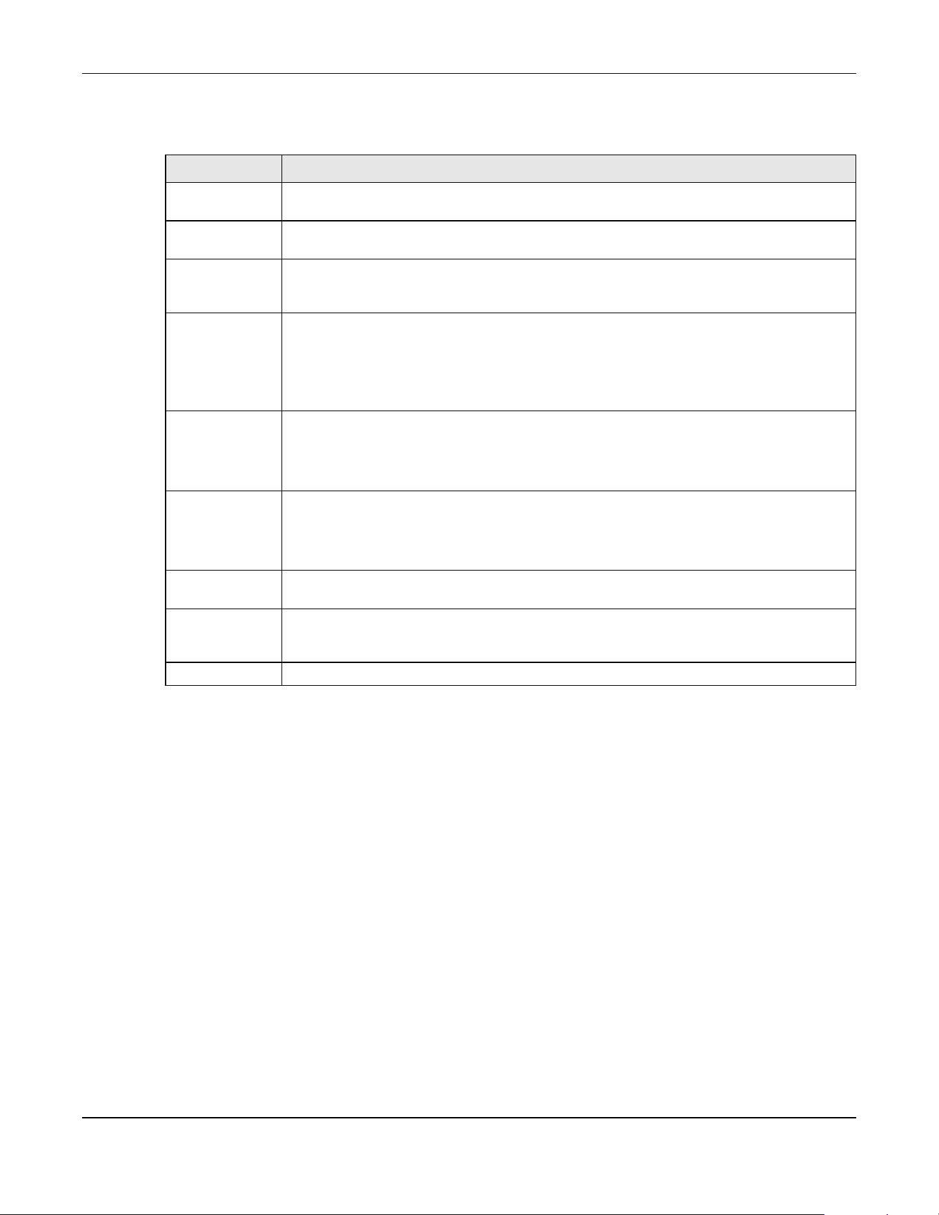
Chapter 72 Storm Control
XGS2220 Series User’s Guide
537
The following table describes the labels in this screen.
Table 279 SECURITY > Storm Control
LABEL DESCRIPTION
Active Enable the switch button to enable traffic storm control on the Switch. Disable the switch
button to disable this feature.
SLOT This field appears only in Stacking mode. Click the drop-down list to choose the slot number of
the Switch in a stack.
Port This field displays the port number. In Stacking mode, the first number represents the slot ID and
the second is the port number. Please note that the default stacking ports (the last four ports of
your Switch) cannot be configured. They are reserved for stacking only.
* Settings in this row apply to all ports.
Use this row only if you want to make some settings the same for all ports. Use this row first to set
the common settings and then make adjustments on a port-by-port basis.
Note: Changes in this row are copied to all the ports as soon as you make them.
Broadcast (pkt/s) Select this option to enable and specify how many broadcast packets the Switch accepts per
second on the port.
The Switch will generate a trap and/or log when the actual rate is higher than the specified
threshold.
Multicast (pkt/s) Select this option to enable and specify how many multicast packets the Switch accepts per
second on the port.
The Switch will generate a trap and/or log when the actual rate is higher than the specified
threshold.
DLF (pkt/s) Select this option and specify how many destination lookup failure (DLF) packets the port
receives per second.
Apply Click Apply to save your changes to the Switch’s run-time memory. The Switch loses these
changes if it is turned off or loses power, so use the Save link on the top navigation panel to
save your changes to the non-volatile memory when you are done configuring.
Cancel Click Cancel to reset the fields.

Chapter 73 Error-Disable
XGS2220 Series User’s Guide
538
CHAPTER 73
Error-Disable
73.1 Error-Disable Overview
This chapter shows you how to configure the rate limit for control packets on a port, and set the Switch
to take an action (such as to shut down a port or stop sending packets) on a port when the Switch
detects a pre-configured error. It also shows you how to configure the Switch to automatically undo the
action after the error is gone.
73.1.1 CPU Protection Overview
Switches exchange protocol control packets in a network to get the latest networking information. If a
switch receives large numbers of control packets, such as ARP, BPDU or IGMP packets, which are to be
processed by the CPU, the CPU may become overloaded and be unable to handle regular tasks
properly.
The CPU protection feature allows you to limit the rate of ARP, BPDU and IGMP packets to be delivered
to the CPU on a port. This enhances the CPU efficiency and protects against potential DoS attacks or
errors from other networks. You then can choose to drop control packets that exceed the specified rate
limit or disable a port on which the packets are received.
73.1.2 Error-Disable Recovery Overview
Some features, such as loop guard or CPU protection, allow the Switch to shut down a port or discard
specific packets on a port when an error is detected on the port. For example, if the Switch detects that
packets sent out the ports loop back to the Switch, the Switch can shut down the ports automatically.
After that, you need to enable the ports or allow the packets on a port manually through the Web
Configurator or the commands. With error-disable recovery, you can set the disabled ports to become
active or start receiving the packets again after the time interval you specify.
73.1.3 What You Can Do
• Use the Errdisable Status screen (Section 73.2 on page 539) to view whether the Switch detected that
control packets exceeded the rate limit configured for a port or a port is disabled according to the
feature requirements and what action you configure, and related information.
• Use the CPU Protection screen (Section 73.3 on page 541) to limit the maximum number of control
packets (ARP, BPDU and/or IGMP) that the Switch can receive or transmit on a port.
• Use the Errdisable Detect screen (Section 73.4 on page 543) to have the Switch detect whether the
control packets exceed the rate limit configured for a port and configure the action to take once the
limit is exceeded.
• Use the Errdisable Recovery screen (Section 73.5 on page 544) to set the Switch to automatically
undo an action after the error is gone.

Chapter 73 Error-Disable
XGS2220 Series User’s Guide
539
73.2 Error-Disable Status
Use this screen to view whether the Switch detected that control packets exceeded the rate limit
configured for a port or a port is disabled according to the feature requirements and what action you
configure, and related information. Click SECURITY > Errdisable > Errdisable Status to display the screen
as shown.
Figure 426 SECURITY > Errdisable > Errdisable Status (Standalone Mode)
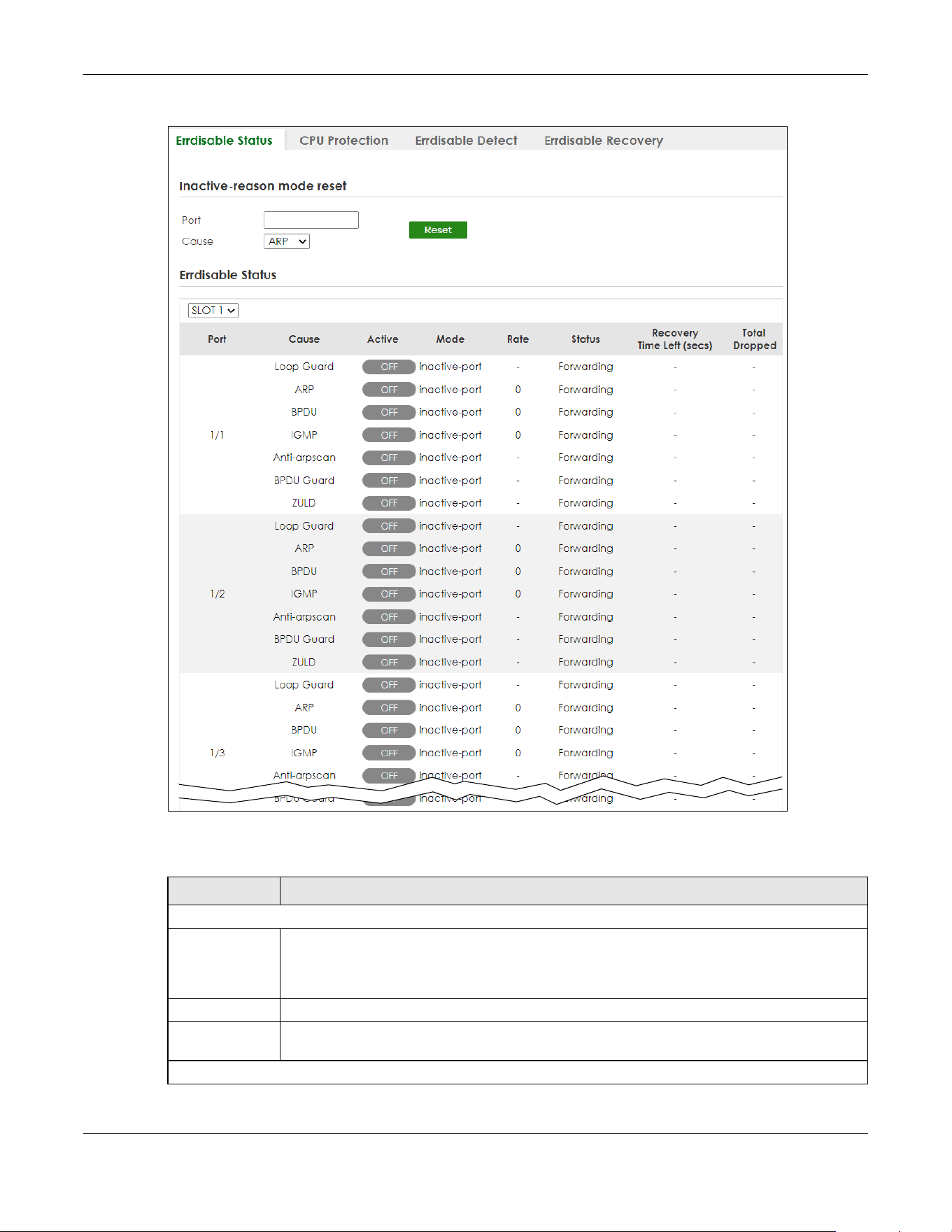
Chapter 73 Error-Disable
XGS2220 Series User’s Guide
540
Figure 427 SECURITY > Errdisable > Errdisable Status (Stacking Mode)
The following table describes the labels in this screen.
Table 280 SECURITY > Errdisable > Errdisable Status
LABEL DESCRIPTION
Inactive-reason mode reset
Port Enter the number of the ports (separated by a comma) on which you want to reset inactive-
reason status. In Stacking mode, the first number represents the slot and the second the port
number. Enter 1/1-1/24,2/23 for ports 1 to 24 for the Switch in slot 1 and port 23 for the Switch in
slot 2, for example.
Cause Select the cause of inactive-reason mode you want to reset here.
Reset Click to reset the specified ports to handle ARP, BPDU or IGMP packets instead of ignoring them,
if the ports is in inactive-reason mode.
Errdisable Status

Chapter 73 Error-Disable
XGS2220 Series User’s Guide
541
73.3 CPU Protection Setup
Use this screen to limit the maximum number of control packets (ARP, BPDU and/or IGMP) that the
Switch can receive or transmit on a port. Click SECURITY > Errdisable > CPU Protection to display the
screen as shown.
Note: After you configure this screen, make sure you also enable error detection for the
specific control packets in the SECURITY > Errdisable > Errdisable Detect screen.
SLOT This field appears only in Stacking mode. Click the drop-down list to choose the slot number of
the Switch in a stack.
Port This field displays the port number. In Stacking mode, the first number represents the slot ID and
the second is the port number. Please note that the default stacking ports (the last four ports of
your Switch) cannot be configured. They are reserved for stacking only.
Cause This displays the type of the control packet received on the port or the feature enabled on the
port and causing the Switch to take the specified action.
Active This field displays whether the control packets (ARP, BPDU, and/or IGMP) on the port is being
detected or not. It also shows whether loop guard, anti-arp scanning, BPDU guard or ZULD is
enabled on the port.
Mode This field shows the action that the Switch takes for the cause.
• inactive-port – The Switch disables the port.
• inactive-reason – The Switch drops all the specified control packets (such as BPDU) on the
port.
• rate-limitation – The Switch drops the additional control packets the ports has to handle in
every one second.
Rate This field displays how many control packets this port can receive or transmit per second. It can
be adjusted in CPU Protection. 0 means no rate limit.
Status This field displays the errdisable status.
• Forwarding: The Switch is forwarding packets. Rate-limitation mode is always in Forwarding
status.
• Err-disable: The Switch disables the port on which the control packets are received
(inactive-port) or drops specified control packets on the port (inactive-reason).
Recovery
Time Left
(secs)
This field displays the time (seconds) left before the ports becomes active of Errdisable
Recovery.
Total
Dropped
This field displays the total packet number dropped by this port where the packet rate exceeds
the rate of mode rate-limitation.
Table 280 SECURITY > Errdisable > Errdisable Status (continued)
LABEL DESCRIPTION
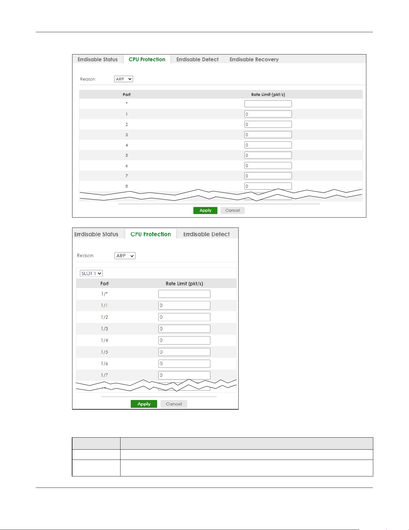
Chapter 73 Error-Disable
XGS2220 Series User’s Guide
542
Figure 428 SECURITY > Errdisable > CPU Protection (Standalone Mode)
Figure 429 SECURITY > Errdisable > CPU Protection (Stacking Mode)
The following table describes the labels in this screen.
Table 281 SECURITY > Errdisable > CPU Protection
LABEL DESCRIPTION
Reason Select the type of control packet you want to configure here.
SLOT This field appears only in Stacking mode. Click the drop-down list to choose the slot number of
the Switch in a stack.

Chapter 73 Error-Disable
XGS2220 Series User’s Guide
543
73.4 Error-Disable Detect Setup
Use this screen to have the Switch detect whether the control packets exceed the rate limit configured
for a port and configure the action to take once the limit is exceeded. Click SECURITY > Errdisable >
Errdisable Detect to display the screen as shown.
Figure 430 SECURITY > Errdisable > Errdisable Detect
The following table describes the labels in this screen.
Port This field displays the port number. In Stacking mode, the first number represents the slot ID and
the second is the port number. Please note that the default stacking ports (the last four ports of
your Switch) cannot be configured. They are reserved for stacking only.
* Use this row to make the setting the same for all ports. Use this row first and then make
adjustments to each port if necessary.
Changes in this row are copied to all the ports as soon as you make them.
Rate Limit (pkt/s) Enter a number from 0 to 256 to specify how many control packets this port can receive or
transmit per second.
0 means no rate limit.
You can configure the action that the Switch takes when the limit is exceeded.
Apply Click Apply to save your changes to the Switch’s run-time memory. The Switch loses these
changes if it is turned off or loses power, so use the Save link on the top navigation panel to save
your changes to the non-volatile memory when you are done configuring.
Cancel Click Cancel to begin configuring this screen afresh.
Table 281 SECURITY > Errdisable > CPU Protection (continued)
LABEL DESCRIPTION
Table 282 SECURITY > Errdisable > Errdisable Detect
LABEL DESCRIPTION
Cause This field displays the types of control packet that may cause CPU overload.
* Use this row to make the setting the same for all entries. Use this row first and then make
adjustments to each entry if necessary.
Changes in this row are copied to all the entries as soon as you make them.
Active Select this option to have the Switch detect if the configured rate limit for a specific control
packet is exceeded and take the action selected below.
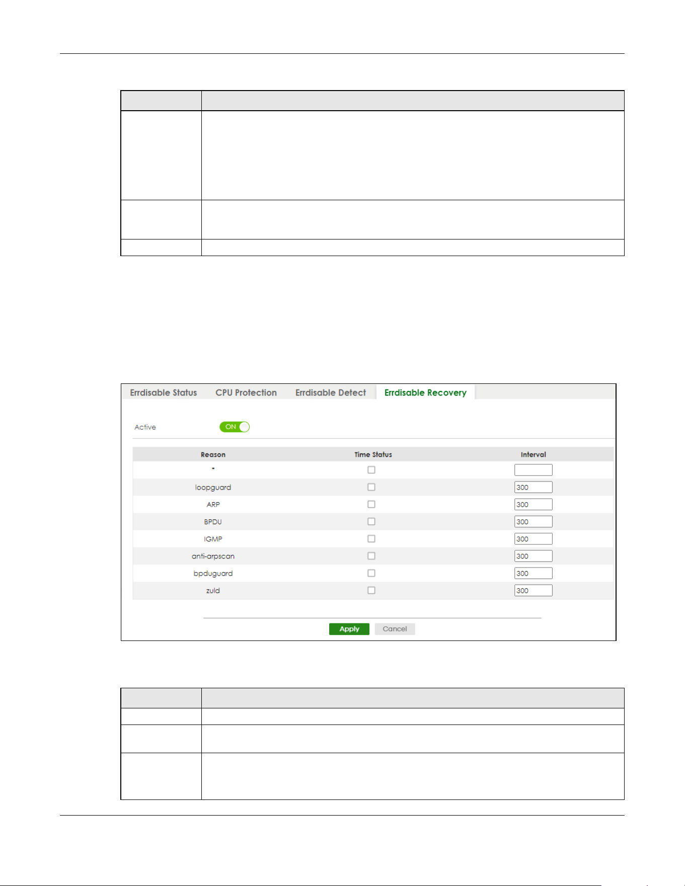
Chapter 73 Error-Disable
XGS2220 Series User’s Guide
544
73.5 Error-Disable Recovery Setup
Use this screen to configure the Switch to automatically undo an action after the error is gone. Click
SECURITY > Errdisable > Errdisable Recovery to display the screen as shown.
Figure 431 SECURITY > Errdisable > Errdisable Recovery
The following table describes the labels in this screen.
Mode Select the action that the Switch takes when the number of control packets exceed the rate
limit on a port, set in the SECURITY > Errdisable > CPU Protection screen.
• inactive-port – The Switch disables the port on which the control packets are received.
• inactive-reason – The Switch drops all the specified control packets (such as BPDU) on the
port.
• rate-limitation – The Switch drops the additional control packets the ports has to handle in
every one second.
Apply Click Apply to save your changes to the Switch’s run-time memory. The Switch loses these
changes if it is turned off or loses power, so use the Save link on the top navigation panel to save
your changes to the non-volatile memory when you are done configuring.
Cancel Click Cancel to begin configuring this screen afresh.
Table 282 SECURITY > Errdisable > Errdisable Detect (continued)
LABEL DESCRIPTION
Table 283 SECURITY > Errdisable > Errdisable Recovery
LABEL DESCRIPTION
Active Enable the switch button to turn on the error-disable recovery function on the Switch.
Reason This field displays the supported features that allow the Switch to shut down a port or discard
packets on a port according to the feature requirements and what action you configure.
* Use this row to make the setting the same for all entries. Use this row first and then make
adjustments to each entry if necessary.
Changes in this row are copied to all the entries as soon as you make them.

Chapter 73 Error-Disable
XGS2220 Series User’s Guide
545
Time Status Select this check box to allow the Switch to wait for the specified time interval to activate a port
or allow specific packets on a port, after the error was gone. Clear the check box to turn off this
rule.
Interval Enter the number of seconds (from 30 to 2592000) for the time interval.
Apply Click Apply to save your changes to the Switch’s run-time memory. The Switch loses these
changes if it is turned off or loses power, so use the Save link on the top navigation panel to save
your changes to the non-volatile memory when you are done configuring.
Cancel Click Cancel to begin configuring this screen afresh.
Table 283 SECURITY > Errdisable > Errdisable Recovery (continued)
LABEL DESCRIPTION

Chapter 74 IP Source Guard
XGS2220 Series User’s Guide
546
CHAPTER 74
IP Source Guard
74.1 IP Source Guard Overview
IP source guard consists of the following features:
• DHCP snooping. Use this to filter unauthorized DHCP server packets on the network and to build a
binding table dynamically.
• ARP inspection. Use this to filter unauthorized ARP packets on the network.
• Static IP bindings. Use this to create static bindings in the binding table.
The Switch builds the binding table by snooping DHCP packets (dynamic bindings) and from information
provided manually by administrators (static bindings).
Binding Table
IP source guard uses a binding table to distinguish between authorized and unauthorized ARP packets
in your network. A binding contains these key attributes:
• MAC address
• VLAN ID
• IP address
• Port number
The Switch builds the binding table by snooping DHCP packets (dynamic bindings) and from information
provided manually by administrators (static bindings).
DHCP Snooping
The Switch only allows an authorized DHCP server on a trusted port to assign IP addresses. Unauthorized
DHCP servers will not be able to assign IP addresses to network clients. When the Switch receives a DHCP
server packet from an authorized DHCP server, it inspects the packet and records the DHCP information
in a binding table. The binding records are used in ARP inspection to filter unauthorized ARP packets.
See Section 75.1 on page 551 for more DHCP snooping information.
ARP Inspection
When the Switch receives an ARP packet, it looks up the appropriate MAC address, VLAN ID, IP address,
and port number in the binding table. If there is a binding, the Switch forwards the packet. Otherwise,
the Switch discards the packet.
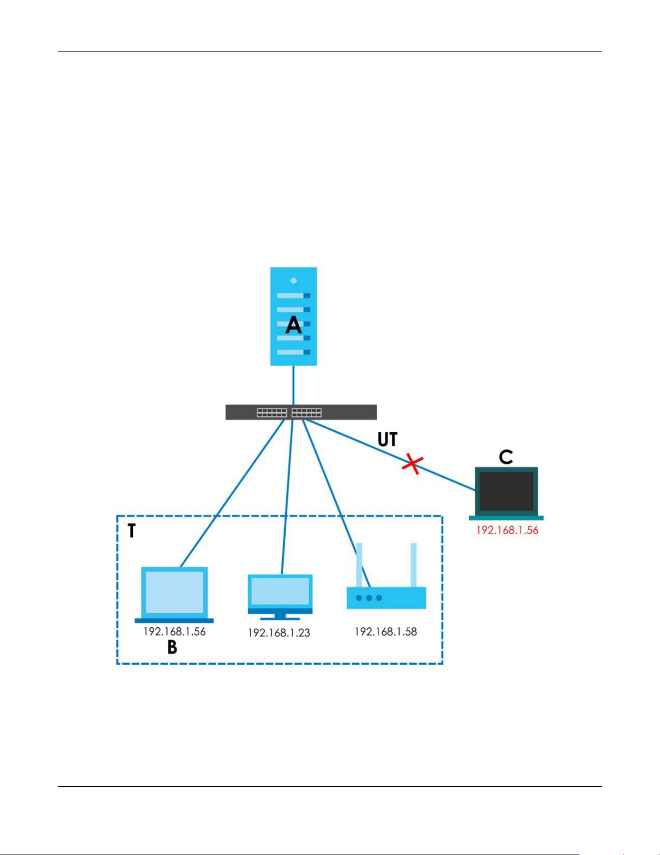
Chapter 74 IP Source Guard
XGS2220 Series User’s Guide
547
If you want to use dynamic bindings to filter unauthorized ARP packets (typical implementation), you
have to enable DHCP snooping before you enable ARP inspection.
The following figure demonstrates a scenario with DHCP snooping and ARP inspection enabled. In this
scenario, we connect an authorized DHCP server (A) and the client devices on the ARP trusted ports (T).
A client device (B) is assigned the IP address 192.168.1.56 by the authorized DHCP server (A). A malicious
host (C) on an untrusted port (UT) puts a wrong MAC address with the IP address 192.168.1.56 in an ARP
reply packet pretending to be client device (B) (192.168.1.56). The Switch snoops DHCP packets sent
from the authorized DHCP server (A) and creates bindings in the binding table. When the Switch
receives ARP packets from an untrusted port (UT), it compares the IP and MAC addresses with the
existing bindings. Since the IP and MAC binding is different from the existing bindings, the Switch blocks
the unauthorized ARP packets sent from the malicious host (C). The malicious host (C) therefore cannot
disguise as client device (B) to build connections with other client devices on your network.
Figure 432 IP Source Guard Example Application
74.1.1 What You Can Do
• Use the IPv4 Source Guard screen (Section 74.2 on page 548) to look at the current bindings for DHCP
snooping and ARP inspection.
• Use the IPv4 Source Guard Static Binding screen (Section 74.3 on page 548) to manage static
bindings for DHCP snooping and ARP inspection.

Chapter 74 IP Source Guard
XGS2220 Series User’s Guide
548
74.2 IPv4 Source Guard
Use this screen to look at the current bindings for DHCP snooping and ARP inspection. Bindings are used
by ARP inspection to distinguish between authorized and unauthorized ARP packets in the network. The
Switch learns the bindings by snooping DHCP packets (dynamic bindings) and from information
provided manually by administrators (static bindings). To open this screen, click SECURITY > IPv4 Source
Guard > IP Source Guard.
Figure 433 SECURITY > IPv4 Source Guard > IP Source Guard
The following table describes the labels in this screen.
74.3 IPv4 Source Guard Static Binding
Use this screen to manage static bindings for DHCP snooping and ARP inspection. Static bindings are
uniquely identified by the MAC address and VLAN ID. Each MAC address and VLAN ID can only be in
one static binding. If you try to create a static binding with the same MAC address and VLAN ID as an
existing static binding, the new static binding replaces the original one. To open this screen, click
SECURITY > IPv4 Source Guard > IP Source Guard > Static Binding.
Table 284 SECURITY > IPv4 Source Guard > IP Source Guard
LABEL DESCRIPTION
Index This field displays a sequential number for each binding.
IP Address This field displays the IP address assigned to the MAC address in the binding.
VID This field displays the source VLAN ID in the binding.
MAC Address This field displays the source MAC address in the binding.
Port This field displays the port number in the binding. If this field is blank, the binding applies to all
ports.
In Stacking mode, the first number represents the slot ID and the second is the port number.
Lease This field displays how many days, hours, minutes, and seconds the binding is valid; for
example, 2d3h4m5s means the binding is still valid for 2 days, 3 hours, 4 minutes, and 5
seconds. This field displays infinity if the binding is always valid (for example, a static binding).
Type This field displays how the Switch learned the binding.
static: This binding was learned from information provided manually by an administrator.
dhcp-snooping: This binding was learned by snooping DHCP packets.
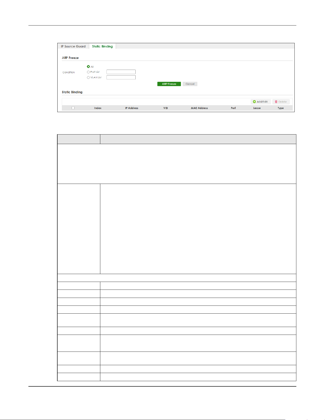
Chapter 74 IP Source Guard
XGS2220 Series User’s Guide
549
Figure 434 SECURITY > IPv4 Source Guard > IP Source Guard > Static Binding
The following table describes the labels in this screen.
Table 285 SECURITY > IPv4 Source Guard > IP Source Guard > Static Binding
LABEL DESCRIPTION
ARP Freeze
ARP Freeze allows you to automatically create static bindings from the current ARP entries (either dynamically
learned or static ARP entries) until the Switch’s binding table is full.
Note: The ARP learning mode should be set to ARP-Request in the NETWORKING > ARP Setup > ARP
Learning screen before you use the ARP Freeze feature.
Condition All – Select this and click ARP Freeze to have the Switch automatically add all the current ARP
entries to the static bindings table.
Port List – Select this and enter the number of the ports (separated by a comma).
You can enter multiple ports separated by (no space) comma (,) or hyphen (-) for a range.
For example, enter “3-5” for ports 3, 4, and 5. Enter “3,5,7” for ports 3, 5, and 7.
In Stacking mode, the first number represents the slot ID and the second is the port number.
Enter “1/1-1/24,2/23” for ports 1 to 24 for the Switch in slot 1 and port 23 for the Switch in slot 2,
for example.
ARP entries learned on the specified ports are added to the static bindings table after you
click ARP Freeze.
VLAN List – Select this and enter the ID number of the VLANs (separated by a comma). ARP
entries for the specified VLANs are added to the static bindings table after you click ARP
Freeze.
Static Binding
Index This field displays a sequential number for each binding.
IP Address This field displays the IP address assigned to the MAC address in the binding.
VID This field displays the source VLAN ID in the binding.
MAC Address This field displays the source MAC address in the binding.
Port This field displays the port number. In Stacking mode, the first number represents the slot ID
and the second is the port number.
Lease This field displays how long the binding is valid.
Type This field displays how the Switch learned the binding.
Static: This binding was learned from information provided manually by an administrator.
Select an entry’s check box to select a specific entry. Otherwise, select the check box in the
table heading row to select all entries.
Add/Edit Click Add/Edit to add a new entry or edit a selected one.
Delete Click Delete to remove the selected entries.

Chapter 74 IP Source Guard
XGS2220 Series User’s Guide
550
74.3.1 Add/Edit IPv4 Source Guard Static Binding
Use this screen to manage static bindings for DHCP snooping and ARP inspection. Static bindings are
uniquely identified by the MAC address and VLAN ID. Each MAC address and VLAN ID can only be in
one static binding. If you try to create a static binding with the same MAC address and VLAN ID as an
existing static binding, the new static binding replaces the original one. Click Add/Edit, or select an entry
and click Add/Edit in the SECURITY > IPv4 Source Guard > IP Source Guard > Static Binding screen to
display this screen.
Figure 435 SECURITY > IPv4 Source Guard > IP Source Guard > Static Binding > Add/Edit (Standalone
Mode)
Figure 436 SECURITY > IPv4 Source Guard > IP Source Guard > Static Binding > Add/Edit (Stacking
Mode)
The following table describes the labels in this screen.
Table 286 SECURITY > IPv4 Source Guard > IP Source Guard > Static Binding > Add/Edit
LABEL DESCRIPTION
IP Address Enter the IP address assigned to the MAC address in the binding.
VLAN Enter the source VLAN ID in the binding.
MAC Address Enter the source MAC address in the binding. If this binding applies to all MAC addresses,
select Any.
Port Specify the ports in the binding. If this binding has one port, select the first radio button and
enter the port number in the field to the right. In Stacking mode, the first field is the slot ID and
the second field is the port number. If this binding applies to all ports, select Any.
Apply Click Apply to save your changes to the Switch’s run-time memory. The Switch loses these
changes if it is turned off or loses power, so use the Save link on the top navigation panel to
save your changes to the non-volatile memory when you are done configuring.
Clear Click Clear to clear the fields to the factory defaults.
Cancel Click Cancel to not save the configuration you make and return to the last screen.

Chapter 75 DHCP Snooping
XGS2220 Series User’s Guide
551
CHAPTER 75
DHCP Snooping
75.1 DHCP Snooping Overview
DHCP snooping filters unauthorized DHCP server packets. The Switch allows only the authorized DHCP
server on a trusted port to assign IP addresses. Clients on your network will only receive DHCP packets
from the authorized DHCP server.
The Switch also builds a DHCP snooping binding table dynamically by snooping DHCP packets
(dynamic bindings). A DHCP snooping binding table contains the IP binding information the Switch
learns from DHCP packets in your network. A binding contains these key attributes:
• MAC address
• VLAN ID
• IP address
• Port number
The following settings demonstrates DHCP snooping on the Switch.
• An authorized DHCP server (A) on a snooped VLAN from the trusted port (T)
• An unauthorized DHCP server (B) on a snooped VLAN from an untrusted port (UT)
• DHCP clients (C) on the untrusted ports (UT).
With DHCP snooping, the Switch blocks all DHCP server packets (DHCP OFFER/ACK) coming from the
untrusted ports (UT). The Switch only forwards the DHCP server packets from the trusted port (T). This
assures that DHCP clients on your network only receive IP addresses assigned by the authorized DHCP
server (A).
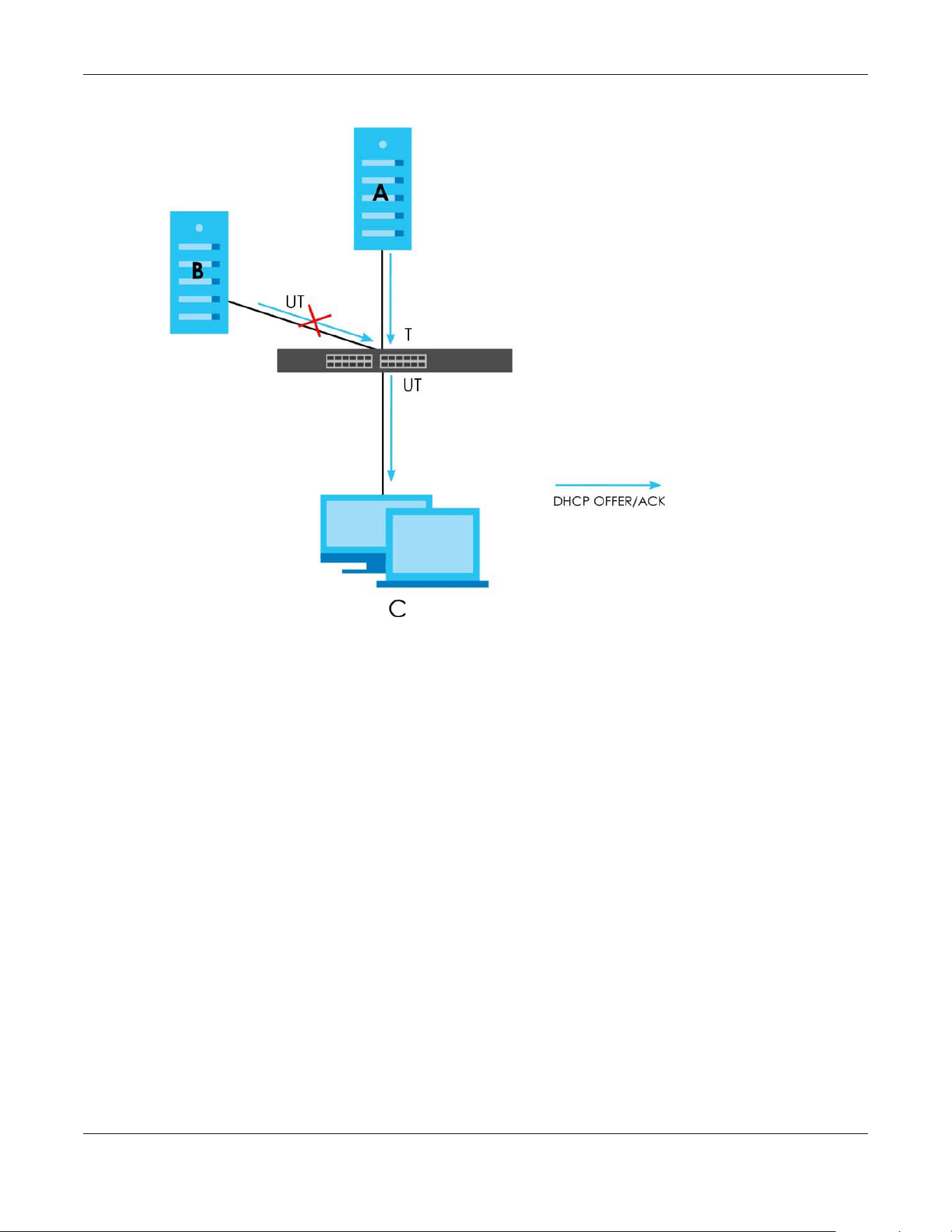
Chapter 75 DHCP Snooping
XGS2220 Series User’s Guide
552
Figure 437 DHCP Snooping Example Application
75.1.1 What You Can Do
• Use the DHCP Snooping Status screen (Section 75.2 on page 552) to look at various statistics about the
DHCP snooping database.
• Use this DHCP Snooping Setup screen (Section 75.3 on page 555) to enable DHCP snooping on the
Switch (not on specific VLAN), specify the VLAN where the default DHCP server is located, and
configure the DHCP snooping database.
• Use the DHCP Snooping Port Setup screen (Section 75.4 on page 556) to specify whether ports are
trusted or untrusted ports for DHCP snooping.
• Use the DHCP Snooping VLAN Setup screen (Section 75.5 on page 558) to enable DHCP snooping on
each VLAN and to specify whether or not the Switch adds DHCP relay agent option 82 information to
DHCP requests that the Switch relays to a DHCP server for each VLAN.
• Use the DHCP Snooping VLAN Port Setup screen (Section 75.6 on page 559) to apply a different DHCP
option 82 profile to certain ports in a VLAN.
75.2 DHCP Snooping Status
Use this screen to look at various statistics about the DHCP snooping database.
To open this screen, click SECURITY > DHCP Snooping > DHCP Snp. Status.

Chapter 75 DHCP Snooping
XGS2220 Series User’s Guide
553
Figure 438 SECURITY > DHCP Snooping > DHCP Snp. Status
The following table describes the labels in this screen.
Table 287 SECURITY > DHCP Snooping > DHCP Snp. Status
LABEL DESCRIPTION
Database Status
This section displays the current settings for the DHCP snooping database. You can configure them in the SECURITY
> DHCP Snooping > DHCP Snp. Setup screen.
Agent URL This field displays the location of the DHCP snooping database.
Write Delay
Timer
This field displays how long (in seconds) the Switch tries to complete a specific update in the
DHCP snooping database before it gives up.
Abort Timer This field displays how long (in seconds) the Switch waits to update the DHCP snooping
database after the current bindings change.
Agent Running This field displays the status of the current update or access of the DHCP snooping
database.
None: The Switch is not accessing the DHCP snooping database.
Read: The Switch is loading dynamic bindings from the DHCP snooping database.
Write: The Switch is updating the DHCP snooping database.
Delay Timer
Expiry
This field displays how much longer (in seconds) the Switch tries to complete the current
update before it gives up. It displays Not Running if the Switch is not updating the DHCP
snooping database right now.
Abort Timer
Expiry
This field displays when (in seconds) the Switch is going to update the DHCP snooping
database again. It displays Not Running if the current bindings have not changed since the
last update.
Last Succeeded
Time
This field displays the last time the Switch updated the DHCP snooping database
successfully.
Last Failed Time This field displays the last time the Switch updated the DHCP snooping database
unsuccessfully.

Chapter 75 DHCP Snooping
XGS2220 Series User’s Guide
554
Last Failed
Reason
This field displays the reason the Switch updated the DHCP snooping database
unsuccessfully.
Counters
This section displays historical information about the number of times the Switch successfully or unsuccessfully read
or updated the DHCP snooping database.
Total Attempts This field displays the number of times the Switch has tried to access the DHCP snooping
database for any reason.
Startup Failures This field displays the number of times the Switch could not create or read the DHCP
snooping database when the Switch started up or a new URL is configured for the DHCP
snooping database.
Successful
Transfers
This field displays the number of times the Switch read bindings from or updated the bindings
in the DHCP snooping database successfully.
Failed Transfers This field displays the number of times the Switch was unable to read bindings from or
update the bindings in the DHCP snooping database.
Successful Reads This field displays the number of times the Switch read bindings from the DHCP snooping
database successfully.
Failed Reads This field displays the number of times the Switch was unable to read bindings from the
DHCP snooping database.
Successful Writes This field displays the number of times the Switch updated the bindings in the DHCP
snooping database successfully.
Failed Writes This field displays the number of times the Switch was unable to update the bindings in the
DHCP snooping database.
Database Detail
First Successful
Access
This field displays the first time the Switch accessed the DHCP snooping database for any
reason.
Last Ignored Bindings Counters
This section displays the number of times and the reasons the Switch ignored bindings the last time it read bindings
from the DHCP binding database. You can clear these counters by restarting the Switch or using CLI commands.
See the Ethernet Switch CLI Reference Guide.
Binding Collisions This field displays the number of bindings the Switch ignored because the Switch already
had a binding with the same MAC address and VLAN ID.
Invalid Interfaces This field displays the number of bindings the Switch ignored because the port number was
a trusted interface or does not exist anymore.
Parse Failures This field displays the number of bindings the Switch ignored because the Switch was unable
to understand the binding in the DHCP binding database.
Expired Leases This field displays the number of bindings the Switch ignored because the lease time had
already expired.
Unsupported
VLANs
This field displays the number of bindings the Switch ignored because the VLAN ID does not
exist anymore.
Last Ignored
Time
This field displays the last time the Switch ignored any bindings for any reason from the DHCP
binding database.
Total Ignored Bindings Counters
This section displays the reasons the Switch has ignored bindings any time it read bindings from the DHCP binding
database. You can clear these counters by restarting the Switch or using CLI commands. See the Ethernet Switch
CLI Reference Guide.
Binding Collisions This field displays the number of bindings the Switch has ignored because the Switch already
had a binding with the same MAC address and VLAN ID.
Invalid Interfaces This field displays the number of bindings the Switch has ignored because the port number
was a trusted interface or does not exist anymore.
Table 287 SECURITY > DHCP Snooping > DHCP Snp. Status (continued)
LABEL DESCRIPTION
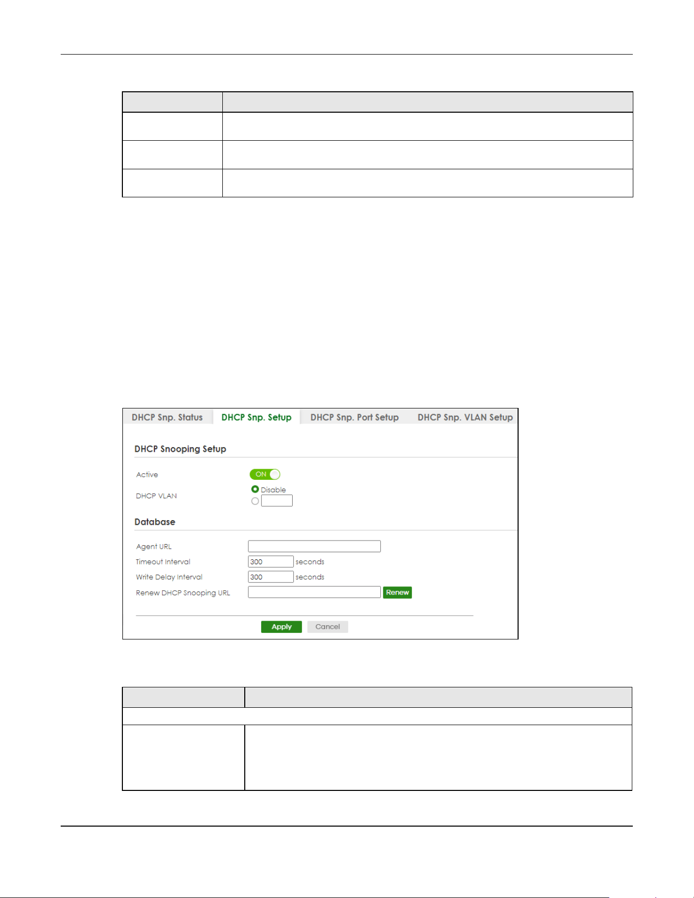
Chapter 75 DHCP Snooping
XGS2220 Series User’s Guide
555
75.3 DHCP Snooping Setup
Use this screen to enable DHCP snooping on the Switch (not on specific VLAN), specify the VLAN where
the default DHCP server is located, and configure the DHCP snooping database. The DHCP snooping
database stores the current bindings on a secure, external TFTP server so that they are still available after
a restart.
To open this screen, click SECURITY > DHCP Snooping > DHCP Snp. Setup.
Note: The input string of any field in this screen should not contain [ ? ], [ | ], [ ' ], [ " ], or [ , ].
Figure 439 SECURITY > DHCP Snooping > DHCP Snp. Setup
The following table describes the labels in this screen.
Parse Failures This field displays the number of bindings the Switch has ignored because the Switch was
unable to understand the binding in the DHCP binding database.
Expired Leases This field displays the number of bindings the Switch has ignored because the lease time
had already expired.
Unsupported
VLANs
This field displays the number of bindings the Switch has ignored because the VLAN ID does
not exist anymore.
Table 287 SECURITY > DHCP Snooping > DHCP Snp. Status (continued)
LABEL DESCRIPTION
Table 288 SECURITY > DHCP Snooping > DHCP Snp. Setup
LABEL DESCRIPTION
DHCP Snooping Setup
Active Enable the switch button to enable DHCP snooping on the Switch. You still have to
enable DHCP snooping on specific VLAN and specify trusted ports.
Note: If DHCP is enabled and there are no trusted ports, DHCP requests will
not succeed.
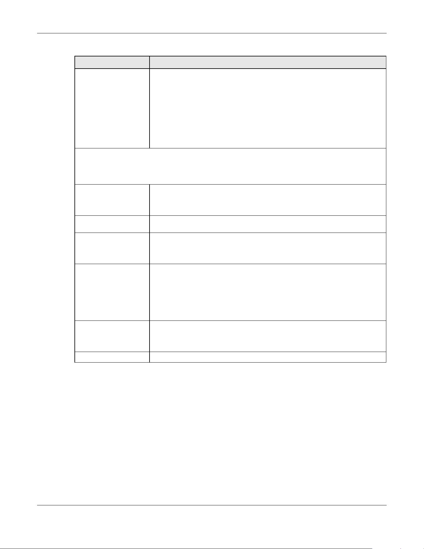
Chapter 75 DHCP Snooping
XGS2220 Series User’s Guide
556
75.4 DHCP Snooping Port Setup
Use this screen to specify whether ports are trusted or untrusted ports for DHCP snooping.
Note: If DHCP snooping is enabled but there are no trusted ports, DHCP requests cannot
reach the DHCP server.
Note: The Switch will drop all DHCP requests if you enable DHCP snooping and there are no
trusted ports.
You can also specify the maximum number for DHCP packets that each port (trusted or untrusted) can
receive each second.
DHCP VLAN Select a VLAN ID if you want the Switch to forward DHCP packets to DHCP servers on a
specific VLAN.
Note: You have to enable DHCP snooping on the DHCP VLAN too.
You can enable Option 82 Profile in the SECURITY > DHCP Snooping > DHCP Snp. VLAN
Setup screen to help the DHCP servers distinguish between DHCP requests from
different VLAN.
Select Disable if you do not want the Switch to forward DHCP packets to a specific
VLAN.
Database
If Timeout Interval is greater than Write Delay Interval, it is possible that the next update is scheduled to occur
before the current update has finished successfully or timed out. In this case, the Switch waits to start the next
update until it completes the current one.
Agent URL Enter the location of the DHCP snooping database. The location should be expressed
like this: tftp://{domain name or IP address}/directory, if applicable/file name; for
example, tftp://192.168.10.1/database.txt. You can enter up to 256 printable ASCII
characters except [ ? ], [ | ], [ ' ], [ " ] or [ , ].
Timeout Interval Enter how long (10 – 65535 seconds) the Switch tries to complete a specific update in
the DHCP snooping database before it gives up.
Write Delay Interval Enter how long (10 – 65535 seconds) the Switch waits to update the DHCP snooping
database the first time the current bindings change after an update. Once the next
update is scheduled, additional changes in current bindings are automatically
included in the next update.
Renew DHCP
Snooping URL
Enter the location of a DHCP snooping database, and click Renew if you want the
Switch to load it. You can use this to load dynamic bindings from a different DHCP
snooping database than the one specified in Agent URL.
When the Switch loads dynamic bindings from a DHCP snooping database, it does not
discard the current dynamic bindings first. If there is a conflict, the Switch keeps the
dynamic binding in volatile memory and updates the Binding Collisions counter in the
DHCP Snooping Status screen (Section 75.2 on page 552).
Apply Click Apply to save your changes to the Switch’s run-time memory. The Switch loses
these changes if it is turned off or loses power, so use the Save link on the top
navigation panel to save your changes to the non-volatile memory when you are
done configuring.
Cancel Click this to reset the values in this screen to their last-saved values.
Table 288 SECURITY > DHCP Snooping > DHCP Snp. Setup (continued)
LABEL DESCRIPTION
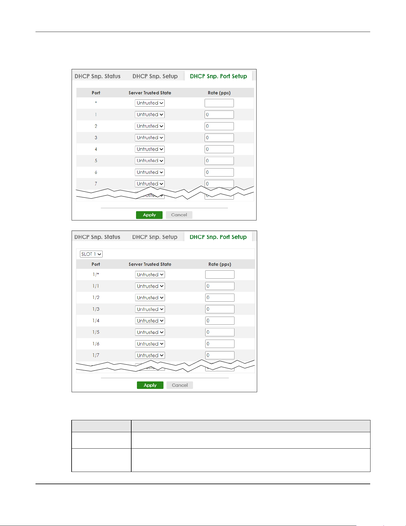
Chapter 75 DHCP Snooping
XGS2220 Series User’s Guide
557
To open this screen, click SECURITY > DHCP Snooping > DHCP Snp. Port Setup.
Figure 440 SECURITY > DHCP Snooping > DHCP Snp. Port Setup (Standalone Mode)
Figure 441 SECURITY > DHCP Snooping > DHCP Snp. Port Setup (Stacking Mode)
The following table describes the labels in this screen.
Table 289 SECURITY > DHCP Snooping > DHCP Snp. Port Setup
LABEL DESCRIPTION
SLOT This field appears only in Stacking mode. Click the drop-down list to choose the slot number
of the Switch in a stack.
Port This field displays the port number. In Stacking mode, the first number represents the slot ID
and the second is the port number. Please note that the default stacking ports (the last four
ports of your Switch) cannot be configured. They are reserved for stacking only.
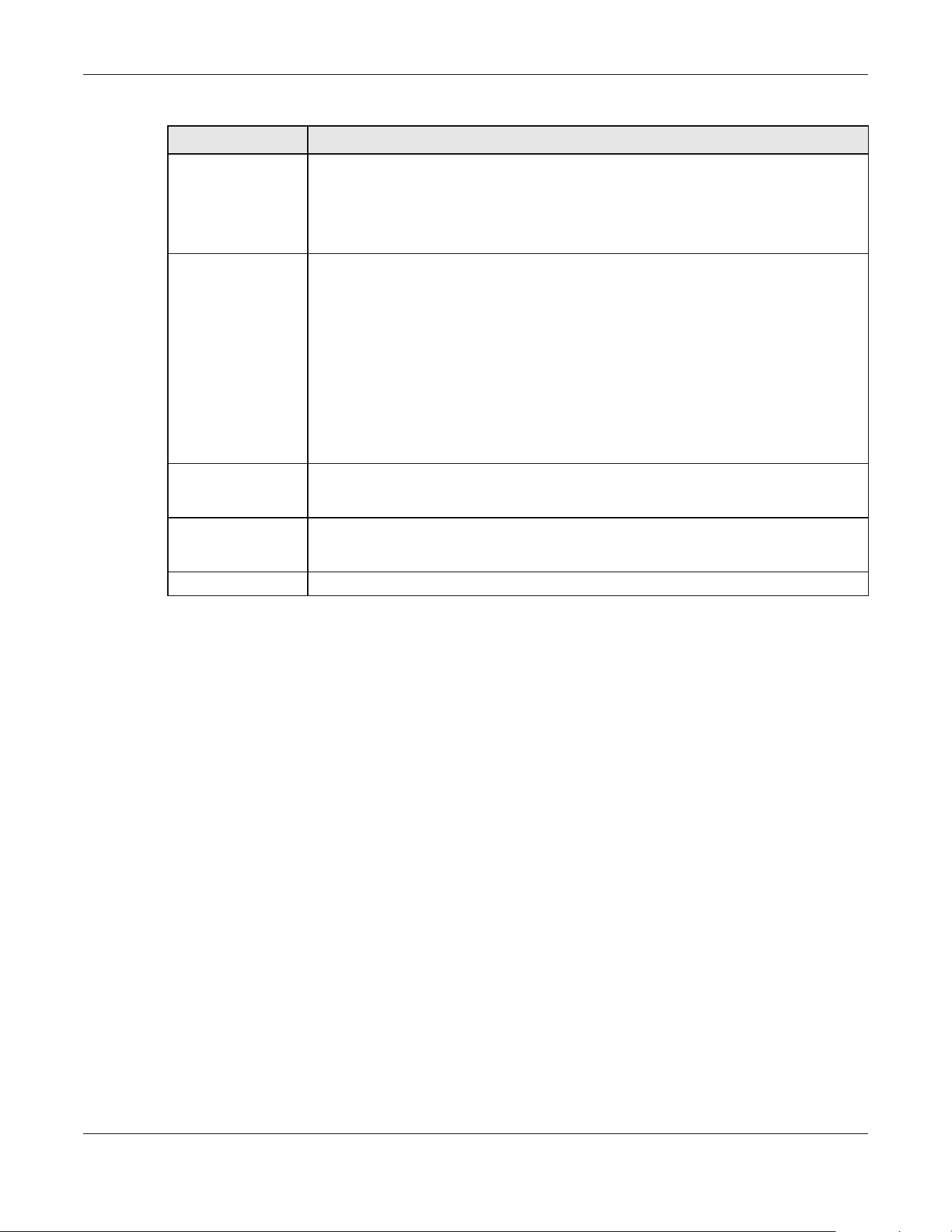
Chapter 75 DHCP Snooping
XGS2220 Series User’s Guide
558
75.5 DHCP Snooping VLAN Setup
Use this screen to enable DHCP snooping on each VLAN and to specify whether or not the Switch adds
DHCP relay agent option 82 information to DHCP requests that the Switch relays to a DHCP server for
each VLAN.
To open this screen, click SECURITY > DHCP Snooping > DHCP Snp. VLAN Setup.
* Settings in this row apply to all ports.
Use this row only if you want to make some settings the same for all ports. Use this row first to
set the common settings and then make adjustments on a port-by-port basis.
Note: Changes in this row are copied to all the ports as soon as you make them.
Server Trusted state Select whether this port is a trusted port (Trusted) or an untrusted port (Untrusted).
Trusted ports are connected to DHCP servers or other switches, and the Switch discards
DHCP packets from trusted ports only if the rate at which DHCP packets arrive is too high.
Untrusted ports are connected to subscribers, and the Switch discards DHCP packets from
untrusted ports in the following situations:
• The packet is a DHCP server packet (for example, OFFER, ACK, or NACK).
• The source MAC address and source IP address in the packet do not match any of the
current bindings.
• The packet is a RELEASE or DECLINE packet, and the source MAC address and source
port do not match any of the current bindings.
• The rate at which DHCP packets arrive is too high.
Rate (pps) Specify the maximum number for DHCP packets (1 – 2048) that the Switch receives from
each port each second. The Switch discards any additional DHCP packets. Enter 0 to
disable this limit, which is recommended for trusted ports.
Apply Click Apply to save your changes to the Switch’s run-time memory. The Switch loses these
changes if it is turned off or loses power, so use the Save link on the top navigation panel to
save your changes to the non-volatile memory when you are done configuring.
Cancel Click this to reset the values in this screen to their last-saved values.
Table 289 SECURITY > DHCP Snooping > DHCP Snp. Port Setup (continued)
LABEL DESCRIPTION

Chapter 75 DHCP Snooping
XGS2220 Series User’s Guide
559
Figure 442 SECURITY > DHCP Snooping > DHCP Snp. VLAN Setup
The following table describes the labels in this screen.
75.6 DHCP Snooping VLAN Port Setup
Use this screen to apply a different DHCP option 82 profile to certain ports in a VLAN.
To open this screen, click SECURITY > DHCP Snooping > DHCP Snp. VLAN Port Setup.
Table 290 SECURITY > DHCP Snooping > DHCP Snp. VLAN Setup
LABEL DESCRIPTION
Search VLAN by VID Enter the VLAN ID you want to manage. Use a comma (,) to separate individual VLANs or a
hyphen (-) to indicates a range of VLANs. For example, “3,4” or “3-9”.
Search Click this to display the specified range of VLANs in the section below.
The Number of
VLANs
This displays the number of VLAN search results.
VID This field displays the VLAN ID of each VLAN in the range specified above. If you configure
the * VLAN, the settings are applied to all VLANs.
Enabled Select Yes to enable DHCP snooping on the VLAN. You still have to enable DHCP snooping
on the Switch and specify trusted ports.
Note: The Switch will drop all DHCP requests if you enable DHCP snooping and
there are no trusted ports.
Option 82 Profile Select a pre-defined DHCP option 82 profile that the Switch applies to all ports in the
specified VLANs. The Switch adds the information (such as slot number, port number, VLAN ID
and/or system name) specified in the profile to DHCP requests that it broadcasts to the DHCP
VLAN, if specified, or VLAN. You can specify the DHCP VLAN in the SECURITY > DHCP
Snooping > DHCP Snp. Setup screen.
Apply Click Apply to save your changes to the Switch’s run-time memory. The Switch loses these
changes if it is turned off or loses power, so use the Save link on the top navigation panel to
save your changes to the non-volatile memory when you are done configuring.
Cancel Click this to reset the values in this screen to their last-saved values.
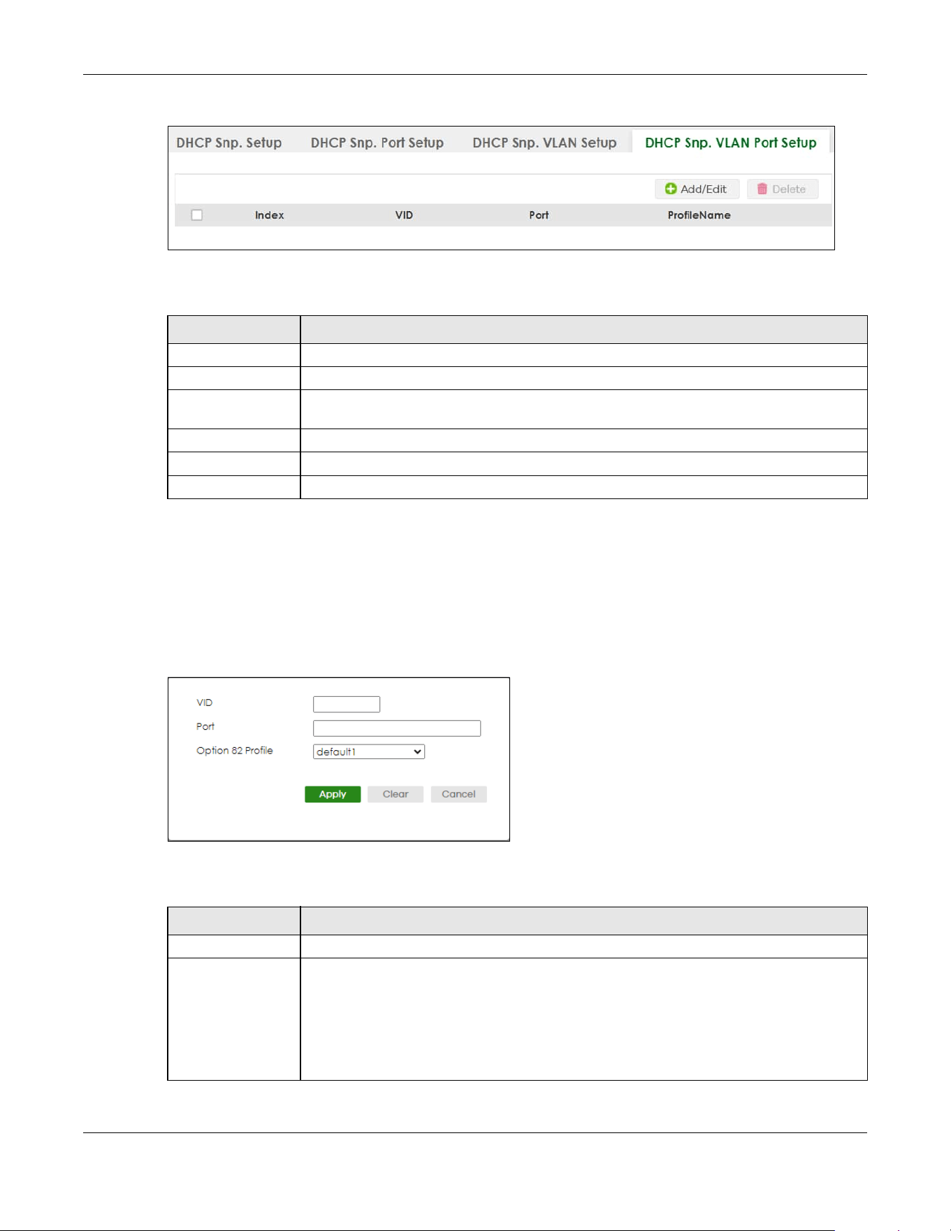
Chapter 75 DHCP Snooping
XGS2220 Series User’s Guide
560
Figure 443 SECURITY > DHCP Snooping > DHCP Snp. VLAN Port Setup
The following table describes the labels in this screen.
75.6.1 Add/EDIT DHCP Snooping VLAN Ports
Use this screen to apply a different DHCP option 82 profile to certain ports in a VLAN.
Click Add/Edit, or select an entry and click Add/Edit in the SECURITY > DHCP Snooping > DHCP Snp. VLAN
Port Setup screen to display this screen.
Figure 444 SECURITY > DHCP Snooping > DHCP Snp. VLAN Port Setup > Add/Edit
The following table describes the labels in this screen.
Table 291 SECURITY > DHCP Snooping > DHCP Snp. VLAN Port Setup
LABEL DESCRIPTION
Index This field displays a sequential number for each entry.
VID This field displays the VLAN to which the ports belongs.
Port This field displays the ports to which the Switch applies the settings. In Stacking mode, the first
number represents the slot and the second the port number.
Profile Name This field displays the DHCP option 82 profile that the Switch applies to the ports.
Add/Edit Click Add/Edit to add a new entry or edit a selected one.
Delete Click Delete to remove the selected entries.
Table 292 SECURITY > DHCP Snooping > DHCP Snp. VLAN Port Setup > Add/Edit
LABEL DESCRIPTION
VID Enter the ID number of the VLAN you want to configure here.
Port Enter the number of ports to which you want to apply the specified DHCP option 82 profile.
You can enter multiple ports separated by (no space) comma (,) or hyphen (-) for a range.
For example, enter “3-5” for ports 3, 4, and 5. Enter “3,5,7” for ports 3, 5, and 7.
In Stacking mode, the first number represents the slot and the second the port number. Enter
1/1-1/24,2/23 for ports 1 to 24 for the Switch in slot 1 and port 23 for the Switch in slot 2, for
example.
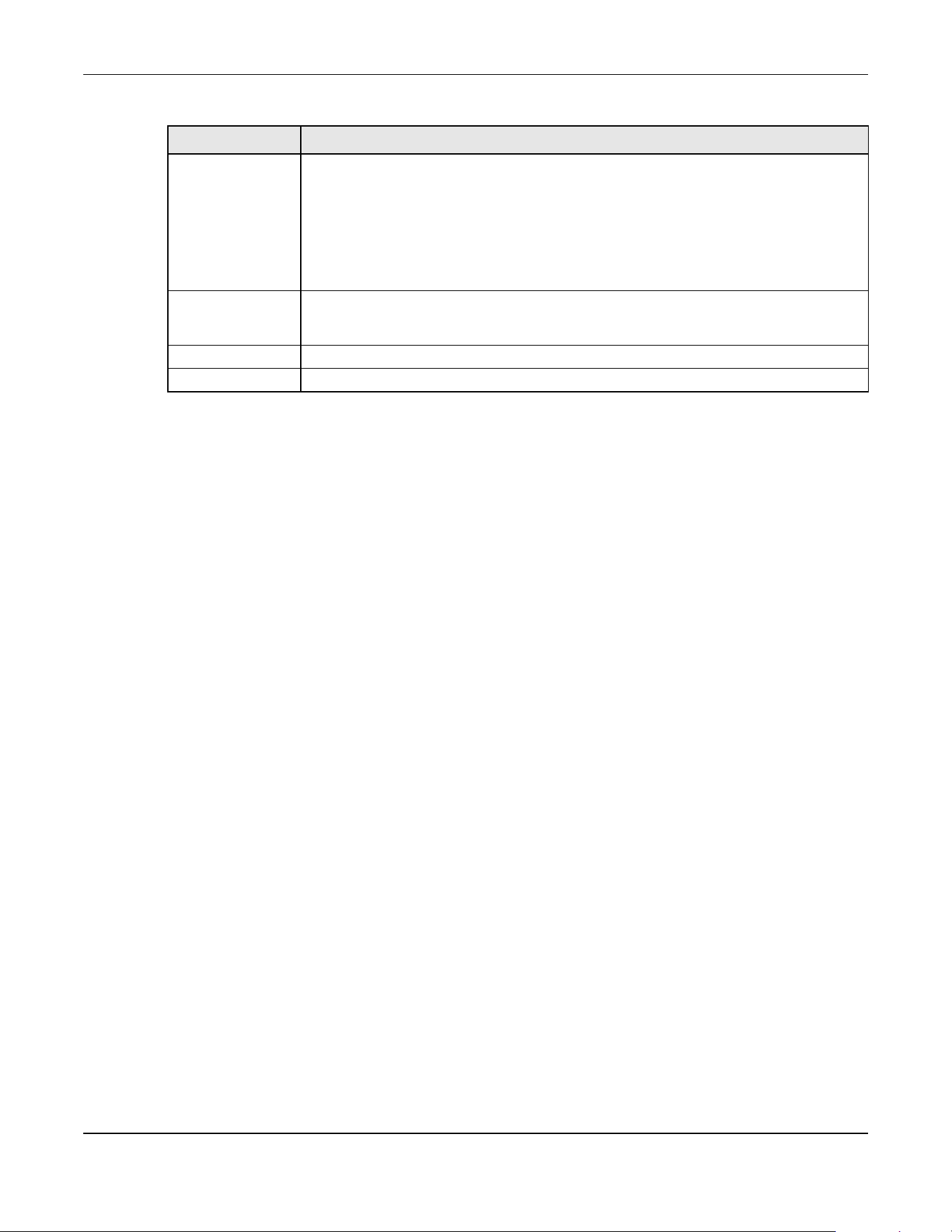
Chapter 75 DHCP Snooping
XGS2220 Series User’s Guide
561
75.7 Technical Reference
This section provides technical background information on the topics discussed in this chapter.
75.7.1 DHCP Snooping Overview
Use DHCP snooping to filter unauthorized DHCP packets on the network and to build the binding table
dynamically. This can prevent clients from getting IP addresses from unauthorized DHCP servers.
75.7.1.1 Trusted vs. Untrusted Ports
Every port is either a trusted port or an untrusted port for DHCP snooping. This setting is independent of
the trusted or untrusted setting for ARP inspection. You can also specify the maximum number for DHCP
packets that each port (trusted or untrusted) can receive each second.
Trusted ports are connected to DHCP servers or other switches. The Switch discards DHCP packets from
trusted ports only if the rate at which DHCP packets arrive is too high. The Switch learns dynamic
bindings from trusted ports.
Note: If DHCP is enabled and there are no trusted ports, DHCP requests will not succeed.
Untrusted ports are connected to subscribers. The Switch discards DHCP packets from untrusted ports in
the following situations:
• The packet is a DHCP server packet (for example, OFFER, ACK, or NACK).
• The rate at which DHCP packets arrive is too high.
75.7.1.2 DHCP Snooping Database
The Switch stores the binding table in volatile memory. If the Switch restarts, it loads static bindings from
permanent memory but loses the dynamic bindings, in which case the devices in the network have to
send DHCP requests again. As a result, it is recommended you configure the DHCP snooping database.
Option 82 Profile Select a pre-defined DHCP option 82 profile that the Switch applies to the specified ports in
this VLAN. The Switch adds the information (such as slot number, port number, VLAN ID and/
or system name) specified in the profile to DHCP requests that it broadcasts to the DHCP
VLAN, if specified, or VLAN. You can specify the DHCP VLAN in the SECURITY > DHCP
Snooping > DHCP Snp. Setup screen.
Note: The profile you select here has priority over the one you select in the
SECURITY > DHCP Snooping > DHCP Snp. VLAN Setup screen.
Apply Click Apply to save your changes to the Switch’s run-time memory. The Switch loses these
changes if it is turned off or loses power, so use the Save link on the top navigation panel to
save your changes to the non-volatile memory when you are done configuring.
Clear Click Clear to clear the fields to the factory defaults.
Cancel Click Cancel to not save the configuration you make and return to the last screen.
Table 292 SECURITY > DHCP Snooping > DHCP Snp. VLAN Port Setup > Add/Edit (continued)
LABEL DESCRIPTION

Chapter 75 DHCP Snooping
XGS2220 Series User’s Guide
562
The DHCP snooping database maintains the dynamic bindings for DHCP snooping and ARP inspection
in a file on an external TFTP server. If you set up the DHCP snooping database, the Switch can reload the
dynamic bindings from the DHCP snooping database after the Switch restarts.
You can configure the name and location of the file on the external TFTP server. The file has the following
format:
Figure 445 DHCP Snooping Database File Format
The <initial-checksum> helps distinguish between the bindings in the latest update and the bindings
from previous updates. Each binding consists of 72 bytes, a space, and another checksum that is used
to validate the binding when it is read. If the calculated checksum is not equal to the checksum in the
file, that binding and all others after it are ignored.
75.7.1.3 DHCP Relay Option 82 Information
The Switch can add information to DHCP requests that it does not discard. This provides the DHCP server
more information about the source of the requests. The Switch can add the following information:
• Slot ID (1 byte), port ID (1 byte), and source VLAN ID (2 bytes)
• System name (up to 32 bytes)
This information is stored in an Agent Information field in the option 82 field of the DHCP headers of client
DHCP request frames.
When the DHCP server responds, the Switch removes the information in the Agent Information field
before forwarding the response to the original source.
You can configure this setting for each source VLAN. This setting is independent of the DHCP relay
settings.
75.7.1.4 Configuring DHCP Snooping
Follow these steps to configure DHCP snooping on the Switch.
1 Enable DHCP snooping on the Switch.
2 Enable DHCP snooping on each VLAN, and configure DHCP relay option 82.
3 Configure trusted and untrusted ports, and specify the maximum number of DHCP packets that each
port can receive per second.
4 Configure static bindings.
<initial-checksum>
TYPE DHCP-SNOOPING
VERSION 1
BEGIN
<binding-1> <checksum-1>
<binding-2> <checksum-1-2>
...
...
<binding-n> <checksum-1-2-..-n>
END
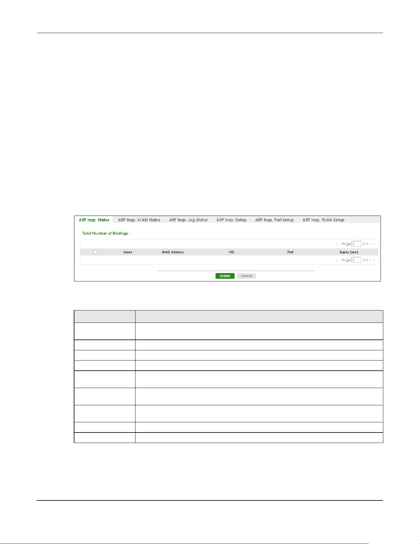
Chapter 76 ARP Inspection
XGS2220 Series User’s Guide
563
CHAPTER 76
ARP Inspection
76.1 ARP Inspection Status
Use this screen to look at the current list of MAC address filters that were created because the Switch
identified an unauthorized ARP packet. When the Switch identifies an unauthorized ARP packet, it
automatically creates a MAC address filter to block traffic from the source MAC address and source
VLAN ID of the unauthorized ARP packet. To open this screen, click SECURITY > IPv4 Source Guard > ARP
Inspection > ARP Insp. Status.
Figure 446 SECURITY > IPv4 Source Guard > ARP Inspection > ARP Insp. Status
The following table describes the labels in this screen.
Table 293 SECURITY > IPv4 Source Guard > ARP Inspection > ARP Insp. Status
LABEL DESCRIPTION
Total Number of
Bindings
This field displays the current number of MAC address filters that were created because the
Switch identified unauthorized ARP packets.
Index This field displays a sequential number for each MAC address filter.
MAC Address This field displays the source MAC address in the MAC address filter.
VID This field displays the source VLAN ID in the MAC address filter.
Port This field displays the source port of the discarded ARP packet. In Stacking mode, the first
number represents the slot and the second the port number.
Expiry (sec) This field displays how long (in seconds) the MAC address filter remains in the Switch. You
can also delete the record manually (Delete).
Select an entry’s check box to select a specific entry. Otherwise, select the check box in the
table heading row to select all entries.
Delete Click this to remove the selected entries.
Cancel Click this to clear the Delete check boxes above.

Chapter 76 ARP Inspection
XGS2220 Series User’s Guide
564
76.2 ARP Inspection VLAN Status
Use this screen to look at various statistics about ARP packets in each VLAN. To open this screen, click
SECURITY > IPv4 Source Guard > ARP Inspection > ARP Insp. VLAN Status.
Figure 447 SECURITY > IPv4 Source Guard > ARP Inspection > ARP Insp. VLAN Status
The following table describes the labels in this screen.
76.3 ARP Inspection Log Status
Use this screen to look at log messages that were generated by ARP packets and that have not been
sent to the syslog server yet. To open this screen, click SECURITY > IPv4 Source Guard > ARP Inspection >
ARP Insp. Log Status.
Table 294 SECURITY > IPv4 Source Guard > ARP Inspection > ARP Insp. VLAN Status
LABEL DESCRIPTION
Search VLAN by VID Specify the VLANs you want to view in the section below. Use a comma (,) to separate
individual VLANs or a hyphen (-) to indicates a range of VLANs. For example, “3,4” or “3-9”.
Search Click this to display the specified range of VLANs in the section below.
The Number of
VLANs
This is the number of VLANs that match the searching criteria and display in the list below.
The number displays when you use the Search button to look for certain VLANs. The default
value is 0.
VID This field displays the VLAN ID of each VLAN in the range specified above.
Received This field displays the total number of ARP packets received from the VLAN since the Switch
last restarted.
Request This field displays the total number of ARP Request packets received from the VLAN since
the Switch last restarted.
Reply This field displays the total number of ARP Reply packets received from the VLAN since the
Switch last restarted.
Forwarded This field displays the total number of ARP packets the Switch forwarded for the VLAN since
the Switch last restarted.
Dropped This field displays the total number of ARP packets the Switch discarded for the VLAN since
the Switch last restarted.
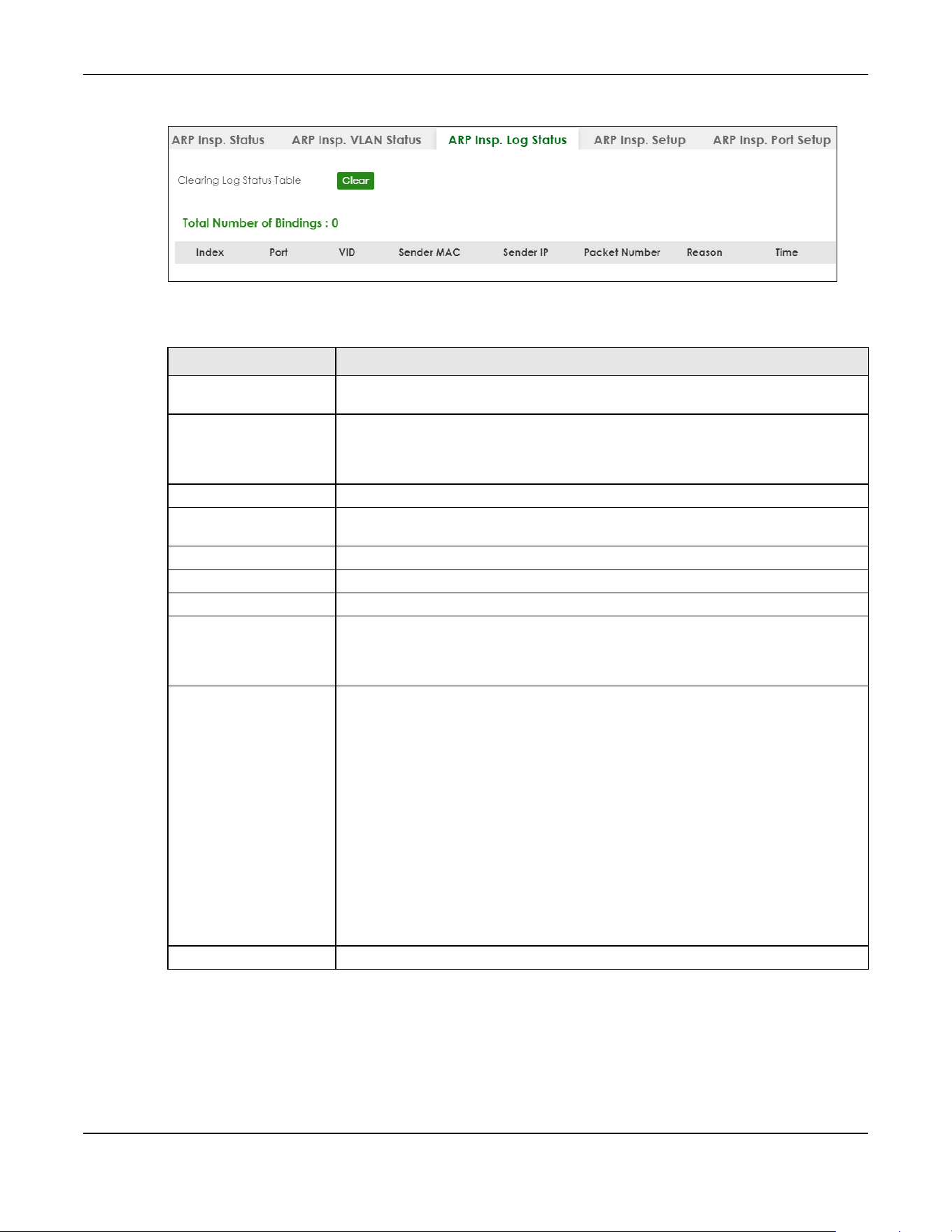
Chapter 76 ARP Inspection
XGS2220 Series User’s Guide
565
Figure 448 SECURITY > IPv4 Source Guard > ARP Inspection > ARP Insp. Log Status
The following table describes the labels in this screen.
76.4 ARP Inspection Setup
Use this screen to enable ARP inspection on the Switch. You can also configure the length of time the
Switch stores records of discarded ARP packets and global settings for the ARP inspection log. To open
Table 295 SECURITY > IPv4 Source Guard > ARP Inspection > ARP Insp. Log Status
LABEL DESCRIPTION
Clearing Log Status Table Click Clear to remove all the log messages that were generated by ARP packets and
that have not been sent to the syslog server yet.
Total number of Bindings This field displays the number of log messages that were generated by ARP packets
and that have not been sent to the syslog server yet. If one or more log messages are
dropped due to unavailable buffer, there is an entry called overflow with the current
number of dropped log messages.
Index This field displays a sequential number for each log message.
Port This field displays the source port of the ARP packet. In Stacking mode, the first number
represents the slot and the second the port number.
VID This field displays the source VLAN ID of the ARP packet.
Sender MAC This field displays the source MAC address of the ARP packet.
Sender IP This field displays the source IP address of the ARP packet.
Packet Number This field displays the number of ARP packets that were consolidated into this log
message. The Switch consolidates identical log messages generated by ARP packets
in the log consolidation interval into one log message. You can configure this interval in
the SECURITY > IPv4 Source Guard > ARP Inspection > ARP Insp. Setup screen.
Reason This field displays the reason the log message was generated.
dhcp deny: An ARP packet was discarded because it violated a dynamic binding with
the same MAC address and VLAN ID.
static deny: An ARP packet was discarded because it violated a static binding with the
same MAC address and VLAN ID.
deny: An ARP packet was discarded because there were no bindings with the same
MAC address and VLAN ID.
dhcp permit: An ARP packet was forwarded because it matched a dynamic binding.
static permit: An ARP packet was forwarded because it matched a static binding.
In the SECURITY > IPv4 Source Guard > ARP Inspection > ARP Insp. VLAN Setup screen,
you can configure the Switch to generate log messages when ARP packets are
discarded or forwarded based on the VLAN ID of the ARP packet.
Time This field displays when the log message was generated.
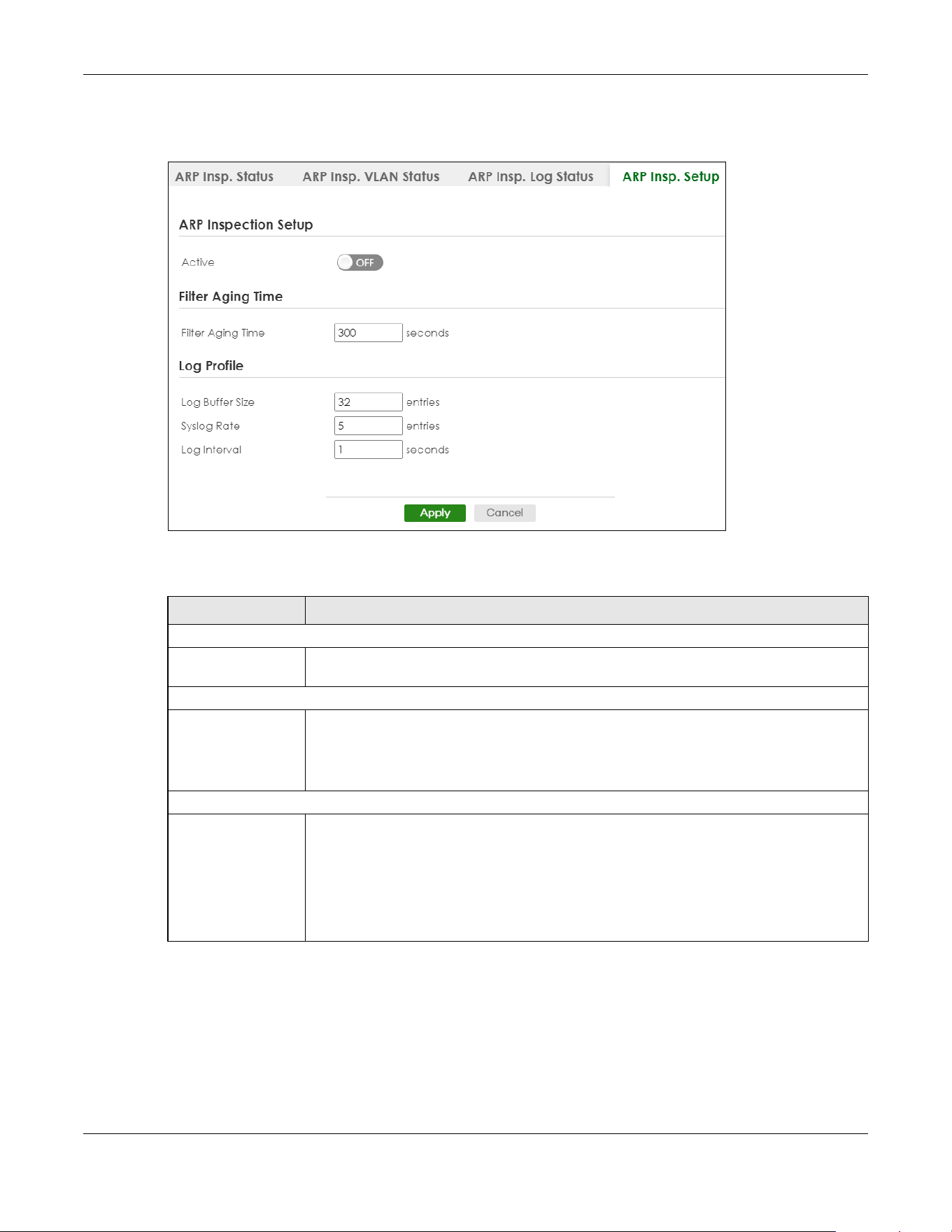
Chapter 76 ARP Inspection
XGS2220 Series User’s Guide
566
this screen, click SECURITY > IPv4 Source Guard > ARP Inspection > ARP Insp. Setup.
Figure 449 SECURITY > IPv4 Source Guard > ARP Inspection > ARP Insp. Setup
The following table describes the labels in this screen.
Table 296 SECURITY > IPv4 Source Guard > ARP Inspection > ARP Insp. Setup
LABEL DESCRIPTION
ARP Inspection Setup
Active Enable the switch button to enable ARP inspection on the Switch. You still have to enable
ARP inspection on specific VLAN and specify trusted ports.
Filter Aging Time
Filter Aging Time This setting has no effect on existing MAC address filters.
Enter how long (1 – 2147483647 seconds) the MAC address filter remains in the Switch after
the Switch identifies an unauthorized ARP packet. The Switch automatically deletes the
MAC address filter afterwards. Type 0 if you want the MAC address filter to be permanent.
Log Profile
Log Buffer Size Enter the maximum number (1 – 1024) of log messages that were generated by ARP packets
and have not been sent to the syslog server yet. Make sure this number is appropriate for
the specified Syslog Rate and Log Interval.
If the number of log messages in the Switch exceeds this number, the Switch stops recording
log messages and simply starts counting the number of entries that were dropped due to
unavailable buffer. Click Clearing Log Status Table in the SECURITY > IPv4 Source Guard >
ARP Inspection > ARP Insp. Log Status screen to clear the log and reset this counter.

Chapter 76 ARP Inspection
XGS2220 Series User’s Guide
567
76.5 ARP Inspection Port Setup
Use this screen to specify whether ports are trusted or untrusted ports for ARP inspection. You can also
specify the maximum rate at which the Switch receives ARP packets on each untrusted port. To open
this screen, click SECURITY > IPv4 Source Guard > ARP Inspection > ARP Insp. Port Setup.
Figure 450 SECURITY > IPv4 Source Guard > ARP Inspection > ARP Insp. Port Setup (Standalone Mode)
Syslog Rate Type the maximum number of syslog messages the Switch can send to the syslog server in
one batch. This number is expressed as a rate because the batch frequency is determined
by the Log Interval. You must configure the syslog server to use this. Enter 0 if you do not
want the Switch to send log messages generated by ARP packets to the syslog server.
The relationship between Syslog Rate and Log Interval is illustrated in the following
examples:
• Four invalid ARP packets per second, Syslog Rate is 5, Log Interval is 1: the Switch sends 4
syslog messages every second.
• Six invalid ARP packets per second, Syslog Rate is 5, Log Interval is 2: the Switch sends 5
syslog messages every 2 seconds.
Log interval Type how often (1 – 86400 seconds) the Switch sends a batch of syslog messages to the
syslog server. Enter 0 if you want the Switch to send syslog messages immediately. See Syslog
Rate for an example of the relationship between Syslog Rate and Log Interval.
Apply Click Apply to save your changes to the Switch’s run-time memory. The Switch loses these
changes if it is turned off or loses power, so use the Save link on the top navigation panel to
save your changes to the non-volatile memory when you are done configuring.
Cancel Click this to reset the values in this screen to their last-saved values.
Table 296 SECURITY > IPv4 Source Guard > ARP Inspection > ARP Insp. Setup (continued)
LABEL DESCRIPTION

Chapter 76 ARP Inspection
XGS2220 Series User’s Guide
568
Figure 451 SECURITY > IPv4 Source Guard > ARP Inspection > ARP Insp. Port Setup (Stacking Mode)
The following table describes the labels in this screen.
Table 297 SECURITY > IPv4 Source Guard > ARP Inspection > ARP Insp. Port Setup
LABEL DESCRIPTION
SLOT This field appears only in Stacking mode. Click the drop-down list to choose the slot
number of the Switch in a stack.
Port This field displays the port number. In Stacking mode, the first number represents the slot
ID and the second is the port number. Please note that the default stacking ports (the last
four ports of your Switch) cannot be configured. They are reserved for stacking only.
* Settings in this row apply to all ports.
Use this row only if you want to make some settings the same for all ports. Use this row first
to set the common settings and then make adjustments on a port-by-port basis.
Note: Changes in this row are copied to all the ports as soon as you make
them.
Trusted State Select whether this port is a trusted port (Trusted) or an untrusted port (Untrusted).
The Switch does not discard ARP packets on trusted ports for any reason.
The Switch discards ARP packets on untrusted ports in the following situations:
• The sender’s information in the ARP packet does not match any of the current
bindings.
• The rate at which ARP packets arrive is too high. You can specify the maximum rate
at which ARP packets can arrive on untrusted ports.
Limit Rate and Burst Interval settings have no effect on trusted ports.
Rate (pps) Specify the maximum rate (1 – 2048 packets per second) at which the Switch receives
ARP packets from each port. The Switch discards any additional ARP packets. Enter 0 to
disable this limit.
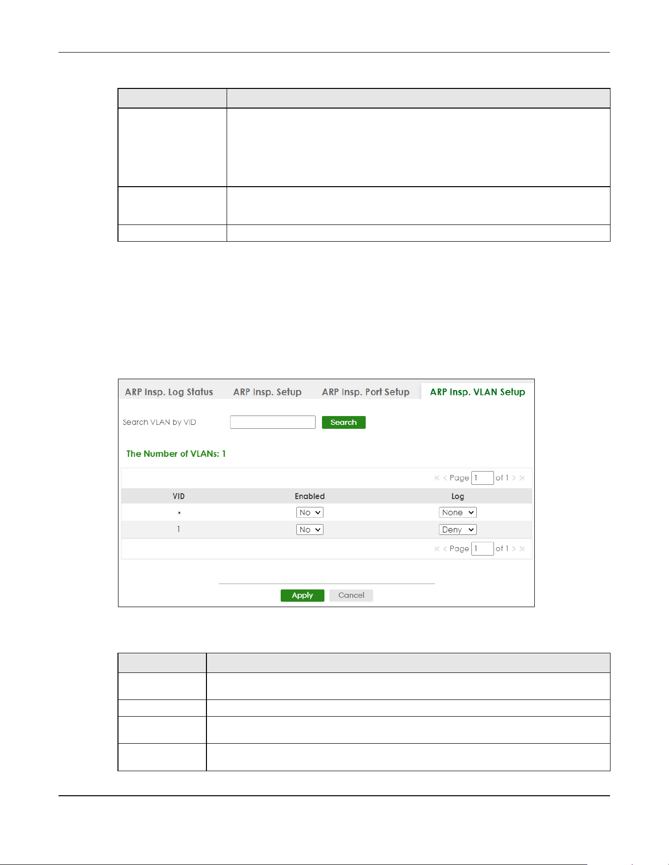
Chapter 76 ARP Inspection
XGS2220 Series User’s Guide
569
76.6 ARP Inspection VLAN Setup
Use this screen to enable ARP inspection on each VLAN and to specify when the Switch generates log
messages for receiving ARP packets from each VLAN. To open this screen, click SECURITY > IPv4 Source
Guard > ARP Inspection > ARP Insp. VLAN Setup.
Figure 452 SECURITY > IPv4 Source Guard > ARP Inspection > ARP Insp. VLAN Setup
The following table describes the labels in this screen.
Burst Interval
(seconds)
The burst interval is the length of time over which the rate of ARP packets is monitored for
each port. For example, if the Rate is 15 pps and the burst interval is 1 second, then the
Switch accepts a maximum of 15 ARP packets in every one-second interval. If the burst
interval is 5 seconds, then the Switch accepts a maximum of 75 ARP packets in every five-
second interval.
Enter the length (1 – 15 seconds) of the burst interval.
Apply Click Apply to save your changes to the Switch’s run-time memory. The Switch loses these
changes if it is turned off or loses power, so use the Save link on the top navigation panel
to save your changes to the non-volatile memory when you are done configuring.
Cancel Click this to reset the values in this screen to their last-saved values.
Table 297 SECURITY > IPv4 Source Guard > ARP Inspection > ARP Insp. Port Setup (continued)
LABEL DESCRIPTION
Table 298 SECURITY > IPv4 Source Guard > ARP Inspection > ARP Insp. VLAN Setup
LABEL DESCRIPTION
Search VLAN by
VID
Specify the VLANs you want to manage in the section below. Use a comma (,) to separate
individual VLANs or a hyphen (-) to indicates a range of VLANs. For example, “3,4” or “3-9”.
Search Click this to display the specified range of VLANs in the section below.
The Number of
VLANs
This display the number of ARP inspection VLAN search results.
VID This field displays the VLAN ID of each VLAN in the range specified above. If you configure the
* VLAN, the settings are applied to all VLANs.

Chapter 76 ARP Inspection
XGS2220 Series User’s Guide
570
76.7 IPv6 Source Guard
The purpose of IPv6 source guard is to distinguish between authorized and unauthorized users by using a
binding table that validates the source of IPv6 traffic. The binding table can be manually created or be
learned through Dynamic Host Configuration Protocol version 6 snooping (DHCPv6 snooping). IPv6
source guard can deny IPv6 traffic from an unknown source. The IPv6 source guard binding table
includes:
• IPv6 address
• IPv6 prefix
• VLAN ID
• Port number
• MAC address
Enable IPv6 source guard on a port for the Switch to check incoming IPv6 packets on that port. A
packet is allowed when it matches any entry in the IPSG binding table. If a user tries to send IPv6 packets
to the Switch that do not match an entry in the IPSG binding table, the Switch will drop these packets.
The Switch forwards matching traffic normally. The IPv6 source guard related screens are available in
standalone mode.
76.8 IPv6 Source Binding Status
Use this screen to look at the current IPv6 dynamic and static bindings and to remove dynamic bindings
based on IPv6 address and/or IPv6 prefix. Bindings are used to distinguish between authorized and
unauthorized packets in the network. The Switch learns the bindings by snooping DHCP packets
(dynamic bindings) and from information provided manually by administrators (static bindings). To open
this screen, click SECURITY > IPv6 Source Guard > IP Static Binding > IP Source Binding Status.
Enabled Select Yes to enable ARP inspection on the VLAN. Select No to disable ARP inspection on the
VLAN.
Log Specify when the Switch generates log messages for receiving ARP packets from the VLAN.
None: The Switch does not generate any log messages when it receives an ARP packet from
the VLAN.
Deny: The Switch generates log messages when it discards an ARP packet from the VLAN.
Permit: The Switch generates log messages when it forwards an ARP packet from the VLAN.
All: The Switch generates log messages every time it receives an ARP packet from the VLAN.
Apply Click Apply to save your changes to the Switch’s run-time memory. The Switch loses these
changes if it is turned off or loses power, so use the Save link on the top navigation panel to
save your changes to the non-volatile memory when you are done configuring.
Cancel Click this to reset the values in this screen to their last-saved values.
Table 298 SECURITY > IPv4 Source Guard > ARP Inspection > ARP Insp. VLAN Setup (continued)
LABEL DESCRIPTION
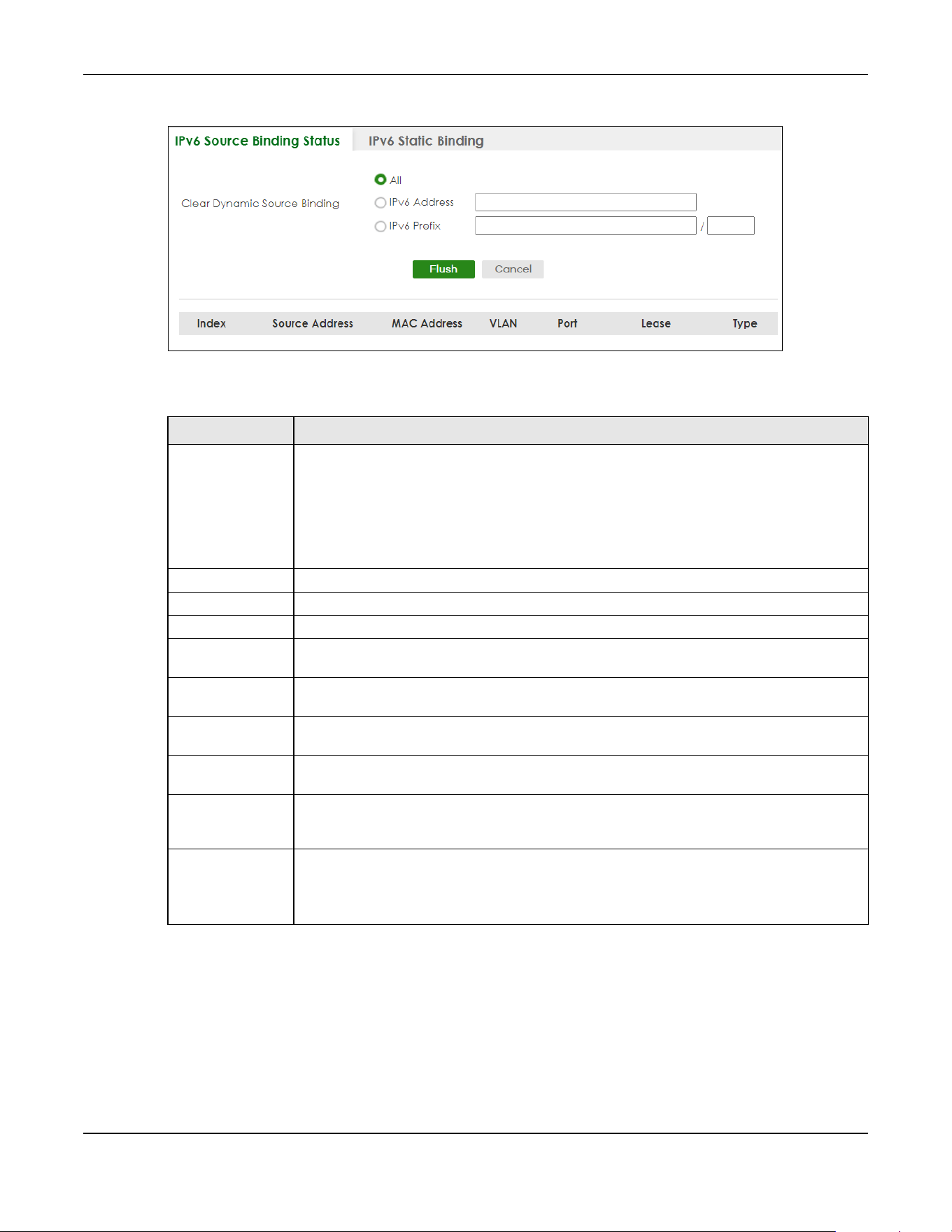
Chapter 76 ARP Inspection
XGS2220 Series User’s Guide
571
Figure 453 SECURITY > IPv6 Source Guard > IP Static Binding > IP Source Binding Status
The following table describes the labels in this screen.
76.9 IPv6 Static Binding
Use this screen to view or configure an IPv6 source guard binding table entry and manage IPv6 static
bindings. Static bindings are uniquely identified by the source IPv6 address / prefix. Each source IPv6
address / prefix can only be in one static binding. If you try to create a static binding with the same
Table 299 SECURITY > IPv6 Source Guard > IP Static Binding > IP Source Binding Status
LABEL DESCRIPTION
Clear Dynamic
Source Binding
Specify how you want the Switch to remove dynamic IPv6 source binding entries when you
click Flush.
• Select All to remove all of the dynamic entries from the IPv6 source binding table.
• Select IPv6 Address and enter an IPv6 address to remove the dynamic entries snooped
with the specified IPv6 address.
• Select IPv6 Prefix and enter a Prefix address to remove the dynamic entries snooped with
the specified Prefix address.
Flush Click this to remove dynamic IPv6 source binding entries according to your selections.
Cancel Click this to reset the values above based or if not applicable, to clear the fields above.
Index This field displays a sequential number for each binding.
Source Address This field displays the source IP address in the binding. If the entry is blank, this field will not be
checked in the binding.
MAC Address This field displays the source MAC address in the binding. If the entry is blank, this field will not
be checked in the binding.
VLAN This field displays the source VLAN ID in the binding. If the entry is blank, this field will not be
checked in the binding.
Port This field displays the port number in the binding. If this field is blank, the binding applies to all
ports.
Lease This field displays how many days, hours, minutes, and seconds the binding is valid; for
example, 2d3h4m5s means the binding is still valid for 2 days, 3 hours, 4 minutes, and 5
seconds. This field displays infinity if the binding is always valid (for example, a static binding).
Type This field displays how the Switch learned the binding.
S: This static binding was learned from information provided manually by an administrator.
DH: This dhcp-snooping binding was learned by snooping DHCP packets.
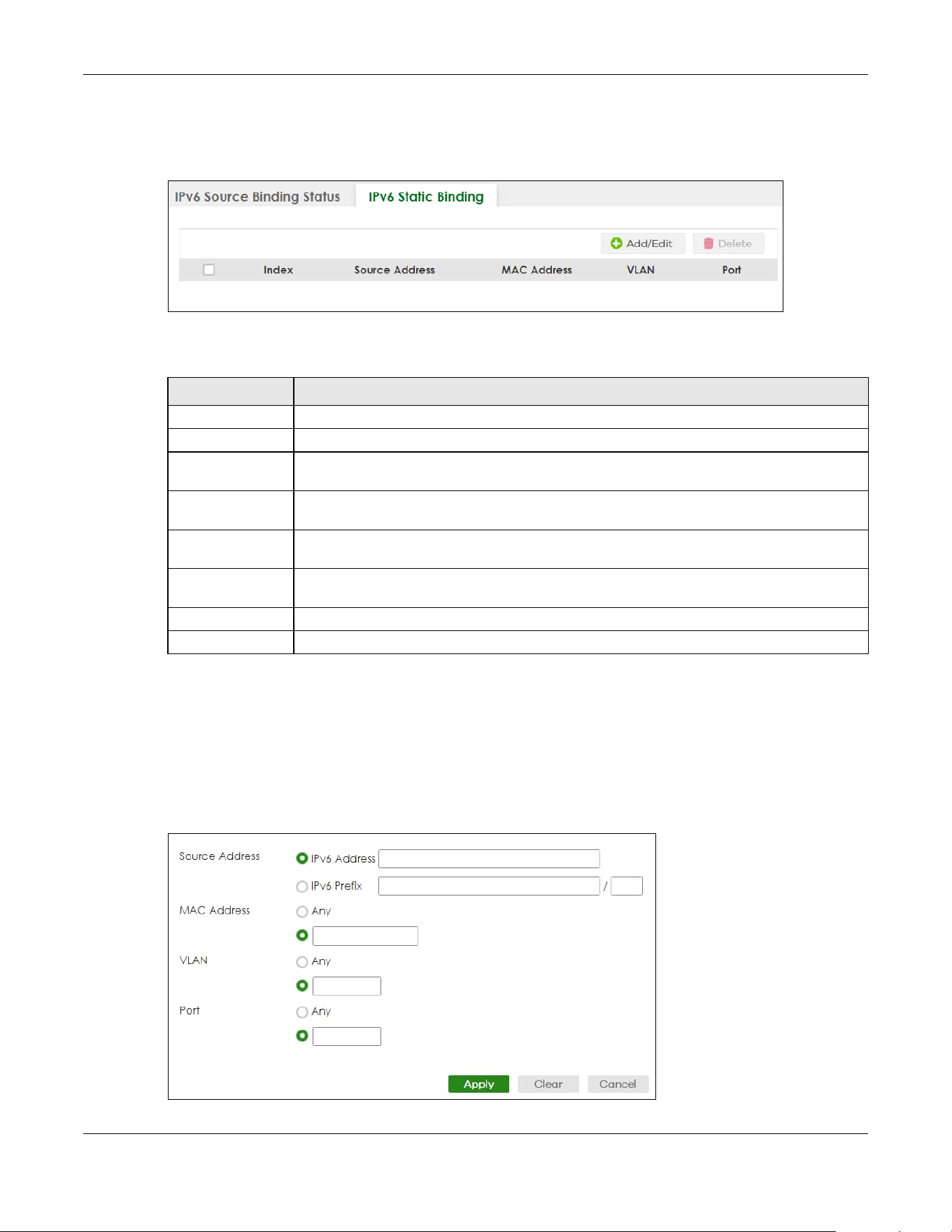
Chapter 76 ARP Inspection
XGS2220 Series User’s Guide
572
source IPv6 address / prefix as an existing static binding, the new static binding replaces the original
one. To open this screen, click SECURITY > IPv6 Source Guard > IPv6 Static Binding > IPv6 Static Binding.
Figure 454 SECURITY > IPv6 Source Guard > IPv6 Static Binding > IPv6 Static Binding
The following table describes the labels in this screen.
76.9.1 Add/Edit IPv6 Static Binding
Use this screen to manually create an IPv6 source guard binding table entry and manage IPv6 static
bindings. Click Add/Edit, or select an entry and click Add/Edit in the SECURITY > IPv6 Source Guard > IPv6
Static Binding > IPv6 Static Binding screen to display this screen.
Figure 455 SECURITY > IPv6 Source Guard > IPv6 Static Binding > IPv6 Static Binding > Add/Edit
(Standalone Mode)
Table 300 SECURITY > IPv6 Source Guard > IPv6 Static Binding > IPv6 Static Binding
LABEL DESCRIPTION
Index This field displays a sequential number for each binding.
Source Address This field displays the IPv6 address or IPv6 prefix and prefix length in the binding.
MAC Address This field displays the source MAC address in the binding. If the entry is blank, this field will not
be checked in the binding.
VLAN This field displays the source VLAN ID in the binding. If the entry is blank, this field will not be
checked in the binding.
Port This field displays the port number in the binding. If this field is blank, the binding applies to all
ports. In Stacking mode, the first number represents the slot and the second the port number
Select an entry’s check box to select a specific entry. Otherwise, select the check box in the
table heading row to select all entries.
Add/Edit Click Add/Edit to add a new entry or edit a selected one.
Delete Click Delete to remove the selected entries.

Chapter 76 ARP Inspection
XGS2220 Series User’s Guide
573
Figure 456 SECURITY > IPv6 Source Guard > IPv6 Static Binding > IPv6 Static Binding > Add/Edit (Stacking
Mode)
The following table describes the labels in this screen.
76.10 IPv6 Source Guard Policy
Use this screen to have IPv6 source guard forward valid IPv6 addresses and/or IPv6 prefixes that are
stored in the binding table and allow or block data traffic from all link-local addresses. To open this
screen, click SECURITY > IPv6 Source Guard > IPv6 Source Guard > IPv6 Source Guard Policy.
•If you select Validate Address and not Validate Prefix, traffic for a binding entry that matches a IPv6
address and VLAN ID, port number, and MAC address will be forwarded. If this binding entry is a IPv6
prefix, the traffic will be denied.
•If you select Validate Prefix and not Validate Address, traffic for a binding entry that matches a IPv6
prefix and VLAN ID, port number, and MAC address will be forwarded. If this binding entry is a IPv6
address, the traffic will be denied.
Table 301 SECURITY > IPv6 Source Guard > IPv6 Static Binding > IPv6 Static Binding > Add/Edit
LABEL DESCRIPTION
Source Address Enter the IPv6 Address or IPv6 Prefix and prefix length in the binding.
MAC Address Enter the source MAC address in the binding. If this binding does not check this field, select
Any.
Note: You cannot choose Any for all three of MAC Address, VLAN and Port. You
must fill in at least one.
VLAN Enter the source VLAN ID in the binding. If this binding does not check this field, select Any.
Port Specify the ports in the binding. If this binding has one port, select the first radio button and
enter the port number in the field to the right. In Stacking mode, the first field is the slot ID and
the second field is the port number. If this binding applies to all ports, select Any.
Apply Click Apply to save your changes to the Switch’s run-time memory. The Switch loses these
changes if it is turned off or loses power, so use the Save link on the top navigation panel to
save your changes to the non-volatile memory when you are done configuring.
Clear Click Clear to clear the fields to the factory defaults.
Cancel Click Cancel to not save the configuration you make and return to the last screen.

Chapter 76 ARP Inspection
XGS2220 Series User’s Guide
574
•If you select both Validate Prefix and Validate Address then traffic matching either IPv6 address or
prefix will be forwarded.
Figure 457 SECURITY > IPv6 Source Guard > IPv6 Source Guard > IPv6 Source Guard Policy
The following table describes the labels in this screen.
76.10.1 Add/Edit an IPv6 Source Guard Policy
Click Add/Edit, or select an entry and click Add/Edit in the SECURITY > IPv6 Source Guard > IPv6 Source
Guard > IPv6 Source Guard Policy screen to display this screen.
Figure 458 SECURITY > IPv6 Source Guard > IPv6 Source Guard > IPv6 Source Guard Policy > Add/Edit
The following table describes the labels in this screen.
Table 302 SECURITY > IPv6 Source Guard > IPv6 Source Guard > IPv6 Source Guard Policy
LABEL DESCRIPTION
Index This field displays a sequential number for each policy.
Name This field displays the descriptive name for identification purposes for this IPv6 source guard
policy.
Validate Address This field displays the Validate Address status for this IPv6 source guard policy.
Validate Prefix This field displays the Validate Prefix status for this IPv6 source guard policy.
Link Local This field displays the Link Local traffic status for this IPv6 source guard policy.
Select an entry’s check box to select a specific entry. Otherwise, select the check box in the
table heading row to select all entries.
Add/Edit Click Add/Edit to add a new entry or edit a selected one.
Delete Click Delete to remove the selected entries.
Table 303 SECURITY > IPv6 Source Guard > IPv6 Source Guard > IPv6 Source Guard Policy > Add/Edit
LABEL DESCRIPTION
Name Enter a descriptive name for identification purposes for this IPv6 source guard policy. You can
enter up to 32 printable ASCII characters except [ ? ], [ | ], [ ' ], [ " ] or [ , ].
Validate Address Select Validate Address to have IPv6 source guard forward valid addresses that are stored in
the binding table.

Chapter 76 ARP Inspection
XGS2220 Series User’s Guide
575
76.11 IPv6 Source Guard Port Setup
Use this screen to apply configured IPv6 source guard policies to ports you specify. Use port * to apply a
policy to all ports. To open this screen, click SECURITY > IPv6 Source Guard > IPv6 Source Guard > IPv6
Source Guard Port Setup.
Figure 459 SECURITY > IPv6 Source Guard > IPv6 Source Guard > IPv6 Source Guard Port Setup
(Standalone Mode)
Validate Prefix Select Validate Prefix to have IPv6 source guard forward valid prefixes that are stored in the
binding table.
Link Local Select Permit to allow data traffic from all link-local addresses; otherwise leave the setting at
Deny. A link-local address is an IPv6 unicast address that can be automatically configured on
any interface using the link-local prefix FE80::/10 and the interface identifier in the modified
EUI-64 format.
Apply Click Apply to save your changes to the Switch’s run-time memory. The Switch loses these
changes if it is turned off or loses power, so use the Save link on the top navigation panel to
save your changes to the non-volatile memory when you are done configuring.
Clear Click Clear to clear the fields to the factory defaults.
Cancel Click Cancel to not save the configuration you make and return to the last screen.
Table 303 SECURITY > IPv6 Source Guard > IPv6 Source Guard > IPv6 Source Guard Policy > Add/Edit
LABEL DESCRIPTION

Chapter 76 ARP Inspection
XGS2220 Series User’s Guide
576
Figure 460 SECURITY > IPv6 Source Guard > IPv6 Source Guard > IPv6 Source Guard Port Setup (Stacking
Mode)
The following table describes the labels in this screen.
76.12 IPv6 Snooping Policy Setup
Use this screen to view and dynamically create an IPv6 source guard binding table using a DHCPv6
snooping policy. A DHCPv6 snooping policy lets the Switch sniff DHCPv6 packets sent from a DHCPv6
server to a DHCPv6 client when it is assigning an IPv6 address. When a DHCPv6 client successfully gets a
valid IPv6 address, DHCPv6 snooping builds the binding table dynamically. To open this screen, click
SECURITY > IPv6 Source Guard > IPv6 Snooping > IPv6 Snooping Policy Setup.
Table 304 SECURITY > IPv6 Source Guard > IPv6 Source Guard > IPv6 Source Guard Port Setup
LABEL DESCRIPTION
SLOT This field appears only in Stacking mode. Click the drop-down list to choose the slot number of
the Switch in a stack.
Port This field displays the port number. In Stacking mode, the first number represents the slot ID
and the second is the port number. Please note that the default stacking ports (the last four
ports of your Switch) cannot be configured. They are reserved for stacking only.
* Settings in this row apply to all ports.
Use this row only if you want to make some settings the same for all ports. Use this row first to set
the common settings and then make adjustments on a port-by-port basis.
Note: Changes in this row are copied to all the ports as soon as you make them.
Policy Name Select an IPv6 source guard policy that the Switch will apply to this port.
Apply Click Apply to save your changes to the Switch’s run-time memory. The Switch loses these
changes if it is turned off or loses power, so use the Save link on the top navigation panel to
save your changes to the non-volatile memory when you are done configuring.
Cancel Click this to reset the values in this screen to their last-saved values.
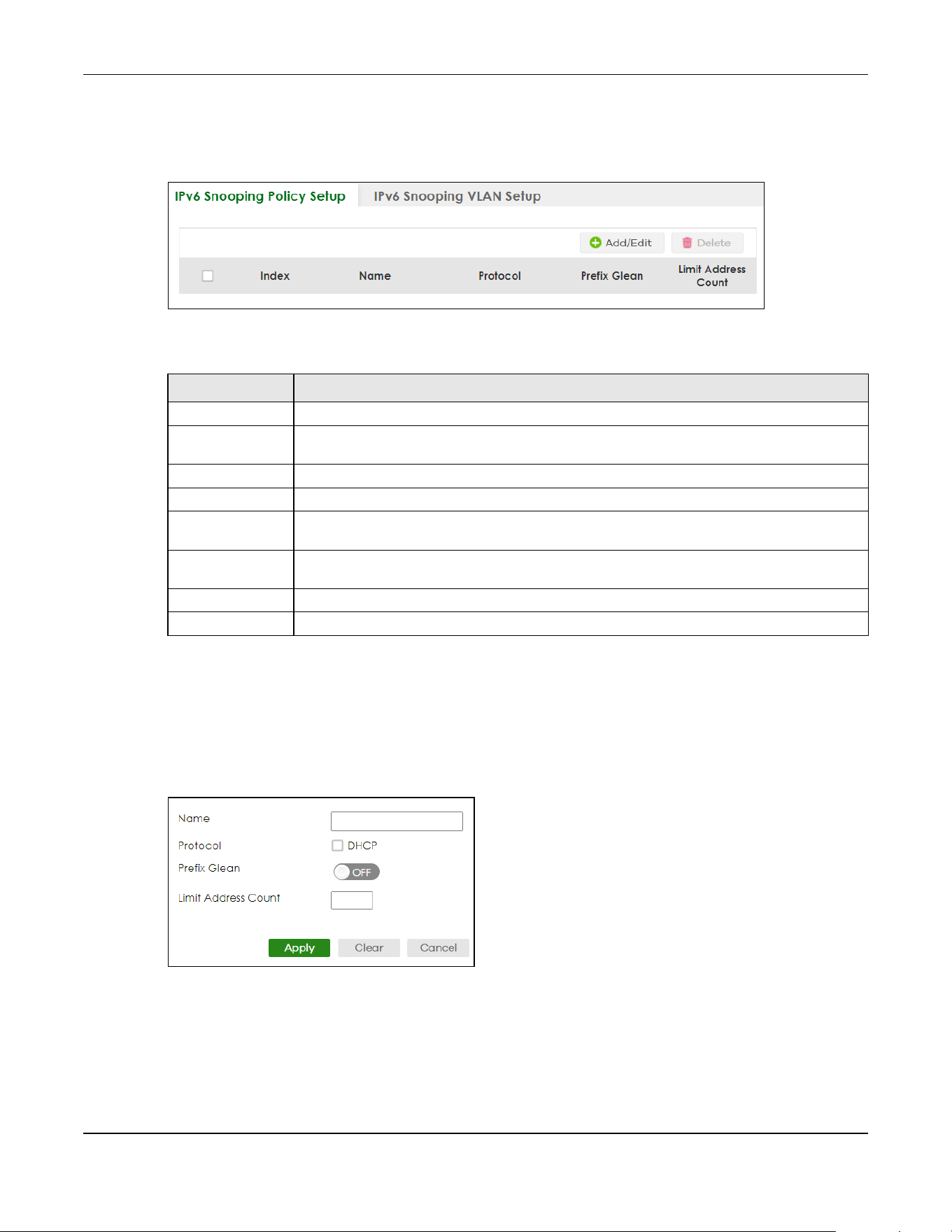
Chapter 76 ARP Inspection
XGS2220 Series User’s Guide
577
Note: If you do not select Protocol and Prefix Glean, then the Switch cannot perform DHCPv6
snooping.
Figure 461 SECURITY > IPv6 Source Guard > IPv6 Snooping > IPv6 Snooping Policy Setup
The following table describes the labels in this screen.
76.12.1 Add/Edit a IPv6 Snooping Policy
Use this screen to dynamically create an IPv6 source guard binding table using a DHCPv6 snooping
policy. Click Add/Edit, or select an entry and click Add/Edit in the SECURITY > IPv6 Source Guard > IPv6
Snooping > IPv6 Snooping Policy Setup screen to display this screen.
Figure 462 SECURITY > IPv6 Source Guard > IPv6 Snooping > IPv6 Snooping Policy Setup > Add/Edit
Table 305 SECURITY > IPv6 Source Guard > IPv6 Snooping > IPv6 Snooping Policy Setup
LABEL DESCRIPTION
Index This field displays a sequential number for each IPv6 snooping policy.
Name This field displays the descriptive name for identification purposes for this IPv6 source guard
policy.
Protocol This field displays the protocols learned from DHCPv6 sniffed packets.
Prefix Glean This field displays the IPv6 prefixes learned from DHCPv6 sniffed packets.
Limit Address
Count
This field displays the number of IPv6 addresses and prefixes learned using the IPv6 snooping
policy.
Select an entry’s check box to select a specific entry. Otherwise, select the check box in the
table heading row to select all entries.
Add/Edit Click Add/Edit to add a new entry or edit a selected one.
Delete Click Delete to remove the selected entries.

Chapter 76 ARP Inspection
XGS2220 Series User’s Guide
578
The following table describes the labels in this screen.
76.13 IPv6 Snooping VLAN Setup
Use this screen to enable a DHCPv6 snooping policy on a specific VLAN interface. To open this screen,
click SECURITY > IPv6 Source Guard > IPv6 Snooping > IPv6 Snp. VLAN Setup.
Figure 463 SECURITY > IPv6 Source Guard > IPv6 Snooping > IPv6 Snp. VLAN Setup
The following table describes the labels in this screen.
Table 306 SECURITY > IPv6 Source Guard > IPv6 Snooping > IPv6 Snooping Policy Setup > Add/Edit
LABEL DESCRIPTION
Name Enter a descriptive name for identification purposes for this IPv6 snooping policy. You can
enter up to 32 printable ASCII characters except [ ? ], [ | ], [ ' ], [ " ] or [ , ].
Protocol Select DHCP to let the Switch sniff DHCPv6 packets sent from a DHCPv6 server to a DHCPv6
client.
Prefix Glean Enable the switch button to learn the IPv6 prefix and length from DHCPv6 sniffed packets.
Limit Address
Count
This is the number of IPv6 addresses and prefixes learned using the IPv6 snooping policy.
Note: The maximum limit address count is the maximum size of the IPv6 source
guard binding table. See the product data sheet for the latest specifications.
Apply Click Apply to save your changes to the Switch’s run-time memory. The Switch loses these
changes if it is turned off or loses power, so use the Save link on the top navigation panel to
save your changes to the non-volatile memory when you are done configuring.
Clear Click Clear to clear the fields to the factory defaults.
Cancel Click Cancel to not save the configuration you make and return to the last screen.
Table 307 SECURITY > IPv6 Source Guard > IPv6 Snooping > IPv6 Snp. VLAN Setup
LABEL DESCRIPTION
Index This field displays a sequential number for each binding.
Interface This field displays the VLAN interface.
Policy This field displays the DHCPv6 snooping policy.
Select an entry’s check box to select a specific entry. Otherwise, select the check box in the
table heading row to select all entries.
Add/Edit Click Add/Edit to add a new entry or edit a selected one.
Delete Click Delete to remove the selected entries.
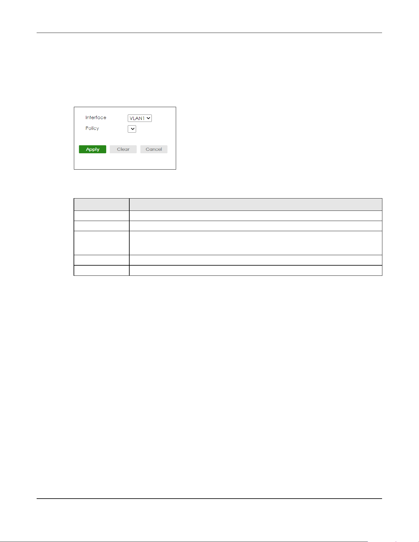
Chapter 76 ARP Inspection
XGS2220 Series User’s Guide
579
76.13.1 Add/Edit an IPv6 Snooping VLAN
Use this screen to add/edit a DHCPv6 snooping policy on a specific VLAN interface. Click Add/Edit, or
select an entry and click Add/Edit in the SECURITY > IPv6 Source Guard > IPv6 Snooping > IPv6 Snp. VLAN
Setup screen to display this screen.
Figure 464 SECURITY > IPv6 Source Guard > IPv6 Snooping > IPv6 Snp. VLAN Setup > Add/Edit
The following table describes the labels in this screen.
76.14 IPv6 DHCP Trust Setup
Use this screen to specify which ports are trusted for DHCPv6 snooping. To open this screen, click
SECURITY > IPv6 Source Guard > DHCPv6 Trust Setup.
Note: DHCPv6 solicit packets are sent from a DHCPv6 client to a DHCPv6 server. Reply
packets from a DHCPv6 server connected to an untrusted port are discarded.
Use port * to have all ports be Untrusted or Trusted.
Table 308 SECURITY > IPv6 Source Guard > IPv6 Snooping > IPv6 Snp. VLAN Setup > Add/Edit
LABEL DESCRIPTION
Interface Select the VLAN interface to apply the selected DHCPv6 snooping policy.
Policy Select the IPv6 snooping policy to apply to this VLAN interface.
Apply Click Apply to save your changes to the Switch’s run-time memory. The Switch loses these
changes if it is turned off or loses power, so use the Save link on the top navigation panel to
save your changes to the non-volatile memory when you are done configuring.
Clear Click Clear to clear the fields to the factory defaults.
Cancel Click Cancel to not save the configuration you make and return to the last screen.

Chapter 76 ARP Inspection
XGS2220 Series User’s Guide
580
Figure 465 SECURITY > IPv6 Source Guard > DHCPv6 Trust Setup (Standalone Mode)
Figure 466 SECURITY > IPv6 Source Guard > DHCPv6 Trust Setup (Stacking Mode)
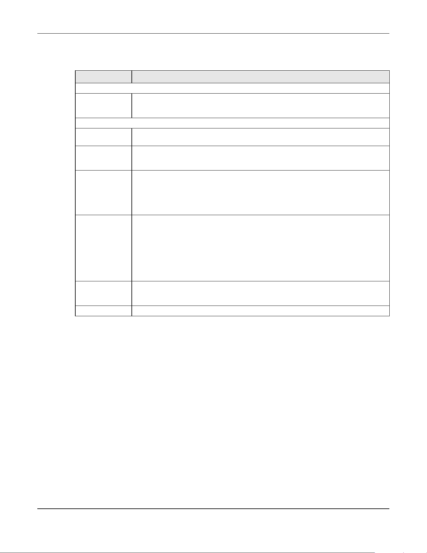
Chapter 76 ARP Inspection
XGS2220 Series User’s Guide
581
The following table describes the labels in this screen.
76.15 Technical Reference
This section provides technical background information on the topics discussed in this chapter.
76.15.1 ARP Inspection Overview
Use ARP inspection to filter unauthorized ARP packets on the network. This can prevent many kinds of
man-in-the-middle attacks, such as the one in the following example.
Table 309 SECURITY > IPv6 Source Guard > DHCPv6 Trust Setup
LABEL DESCRIPTION
Trust Setting
Active Enable the switch button to specify whether ports are trusted or untrusted ports for DHCP
snooping. If you do not select this then IPv6 DHCP Trust is not used and all ports are
automatically trusted.
Port Setting
SLOT This field appears only in Stacking mode. Click the drop-down list to choose the slot number of
the Switch in a stack.
Port This field displays the port number. In Stacking mode, the first number represents the slot ID
and the second is the port number. Please note that the default stacking ports (the last four
ports of your Switch) cannot be configured. They are reserved for stacking only.
* Settings in this row apply to all ports.
Use this row only if you want to make some settings the same for all ports. Use this row first to set
the common settings and then make adjustments on a port-by-port basis.
Note: Changes in this row are copied to all the ports as soon as you make them.
Trusted State Select whether this port is a trusted port (Trusted) or an untrusted port (Untrusted).
Trusted ports are connected to DHCPv6 servers or other switches.
Untrusted ports are connected to subscribers, and the Switch discards DHCPv6 packets from
untrusted ports in the following situations:
• The packet is a DHCPv6 server packet (for example, ADVERTISE, REPLY, or RELAY-REPLY).
• The source MAC address and source IP address in the packet do not match any of the
current bindings.
Apply Click Apply to save your changes to the Switch’s run-time memory. The Switch loses these
changes if it is turned off or loses power, so use the Save link on the top navigation panel to
save your changes to the non-volatile memory when you are done configuring.
Cancel Click this to reset the values in this screen to their last-saved values.

Chapter 76 ARP Inspection
XGS2220 Series User’s Guide
582
Figure 467 Example: Man-in-the-middle Attack
In this example, computer B tries to establish a connection with computer A. Computer X is in the same
broadcast domain as computer A and intercepts the ARP request for computer A. Then, computer X
does the following things:
• It pretends to be computer A and responds to computer B.
• It pretends to be computer B and sends a message to computer A.
As a result, all the communication between computer A and computer B passes through computer X.
Computer X can read and alter the information passed between them.
76.15.1.1 ARP Inspection and MAC Address Filters
When the Switch identifies an unauthorized ARP packet, it automatically creates a MAC address filter to
block traffic from the source MAC address and source VLAN ID of the unauthorized ARP packet. You
can configure how long the MAC address filter remains in the Switch.
These MAC address filters are different than regular MAC address filters.
• They are stored only in volatile memory.
• They do not use the same space in memory that regular MAC address filters use.
• They appear only in the ARP Inspection screens and commands, not in the MAC Address Filter screens
and commands.
76.15.1.2 Trusted vs. Untrusted Ports
Every port is either a trusted port or an untrusted port for ARP inspection. This setting is independent of
the trusted or untrusted setting for DHCP snooping. You can also specify the maximum rate at which the
Switch receives ARP packets on untrusted ports.
The Switch does not discard ARP packets on trusted ports for any reason.
The Switch discards ARP packets on untrusted ports in the following situations:
• The sender’s information in the ARP packet does not match any of the current bindings.
• The rate at which ARP packets arrive is too high.
76.15.1.3 Syslog
The Switch can send syslog messages to the specified syslog server when it forwards or discards ARP
packets. The Switch can consolidate log messages and send log messages in batches to make this
mechanism more efficient.

Chapter 76 ARP Inspection
XGS2220 Series User’s Guide
583
76.15.1.4 Configuring ARP Inspection
Follow these steps to configure ARP inspection on the Switch.
1 Configure DHCP snooping.
Note: It is recommended you enable DHCP snooping at least one day before you enable
ARP inspection so that the Switch has enough time to build the binding table.
2 Enable ARP inspection on each VLAN.
3 Configure trusted and untrusted ports, and specify the maximum number of ARP packets that each port
can receive per second.

Chapter 77 Port Authentication
XGS2220 Series User’s Guide
584
CHAPTER 77
Port Authentication
77.1 Port Authentication Overview
This chapter describes the IEEE 802.1x, MAC, Guest VLAN, and Compound authentication methods.
• IEEE 802.1x
2
– An authentication server validates access to a port based on a user name and
password provided by the user. A user that fails an authentication server can still access the port, but
traffic from the user is forwarded to the guest VLAN port.
• MAC Authentication – An authentication server validates access to a port based on the MAC address
and password of the client.
• Guest VLAN – In either mode, if authentication fails the Switch can still allow the client to access the
network on a Guest VLAN.
• Compound Authentication – An authentication server validates access to a port based on
combination of IEEE 802.1x and MAC Authentication. There are two modes:
• Loose: The client authenticates using either IEEE 802.1x authentication or MAC Authentication.
• Strict: The client authenticates using both IEEE 802.1x authentication and MAC Authentication.
Note: All types of authentication use the RADIUS (Remote Authentication Dial In User Service,
RFC 2138, 2139) protocol to validate users. You must configure a RADIUS server before
enabling port authentication.
Note: If you enable IEEE 802.1x authentication and MAC authentication on the same port, the
Switch performs IEEE 802.1x authentication and MAC authentication. If a user fails to
authenticate either through the IEEE 802.1x or MAC authentication method, then
access to the port is denied.
Note: IEEE 802.1x is not supported by all user operating systems. For details on compatibility,
see your operating system documentation. If your operating system does not support
802.1x, you must install 802.1x client software.
77.1.1 What You Can Do
• Use the 802.1x screen (Section 77.2 on page 586) to activate IEEE 802.1x security.
• Use the MAC Authentication screen (Section 77.3 on page 588) to activate MAC authentication.
• Use the Guest VLAN screen (Section 77.4 on page 591) to enable and assign a guest VLAN to a port.
2. At the time of writing, IEEE 802.1x is not supported by all operating systems. See your operating system
documentation. If your operating system does not support 802.1x, then you may need to install 802.1x
client software.
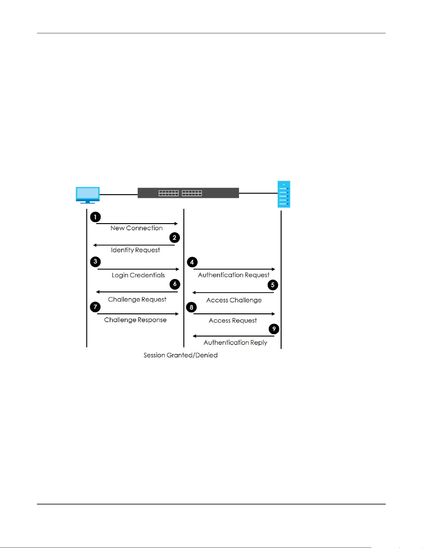
Chapter 77 Port Authentication
XGS2220 Series User’s Guide
585
• Use the Compound Authentication screen (Section 77.5 on page 594) to allow network access for
clients that pass either IEEE 802.1x authentication OR MAC authentication, or pass both IEEE 802.1x
authentication AND MAC authentication.
77.1.2 What You Need to Know
IEEE 802.1x Authentication
The following figure illustrates how a client connecting to a IEEE 802.1x authentication enabled port goes
through a validation process. The Switch prompts the client for login information in the form of a user
name and password after the client responds to its identity request. When the client provides the login
credentials, the Switch sends an authentication request to a RADIUS server. The RADIUS server validates
whether this client is allowed access to the port.
Figure 468 IEEE 802.1x Authentication Process
77.1.3 MAC Authentication
MAC authentication works in a very similar way to IEEE 802.1x authentication. The main difference is that
the Switch does not prompt the client for login credentials. The login credentials are based on the
source MAC address of the client connecting to a port on the Switch along with a password configured
specifically for MAC authentication on the Switch.
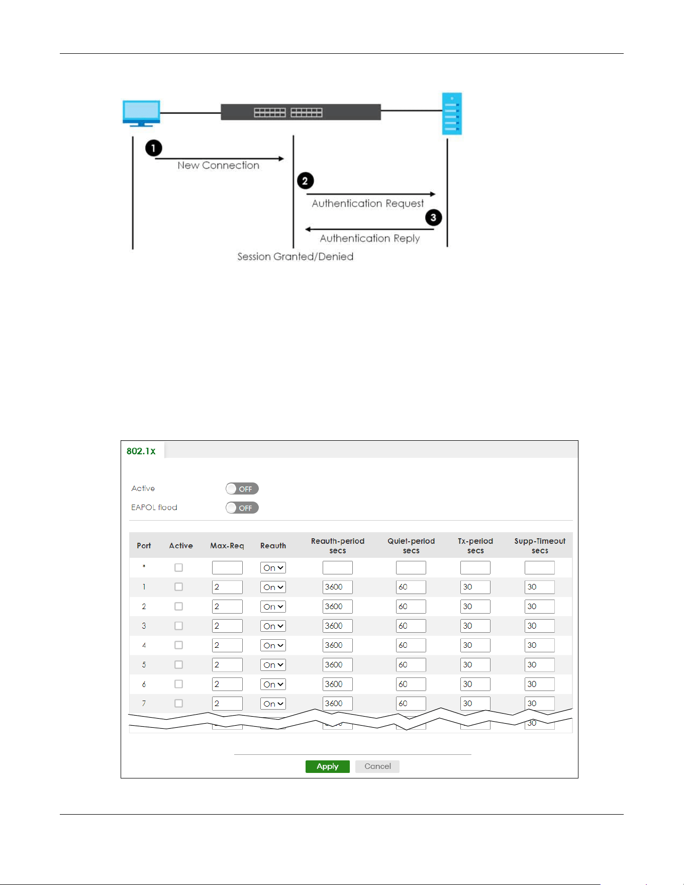
Chapter 77 Port Authentication
XGS2220 Series User’s Guide
586
Figure 469 MAC Authentication Process
Note: To enable port authentication, first activate the port authentication methods (both on
the Switch and the ports), then configure the RADIUS server settings in the SECURITY>
AAA > RADIUS Server Setup screen.
77.2 Activate IEEE 802.1x Security
Use this screen to activate IEEE 802.1x security. Click SECURITY > Port Authentication > 802.1x to display
the configuration screen as shown.
Figure 470 SECURITY > Port Authentication > 802.1x (Standalone Mode)
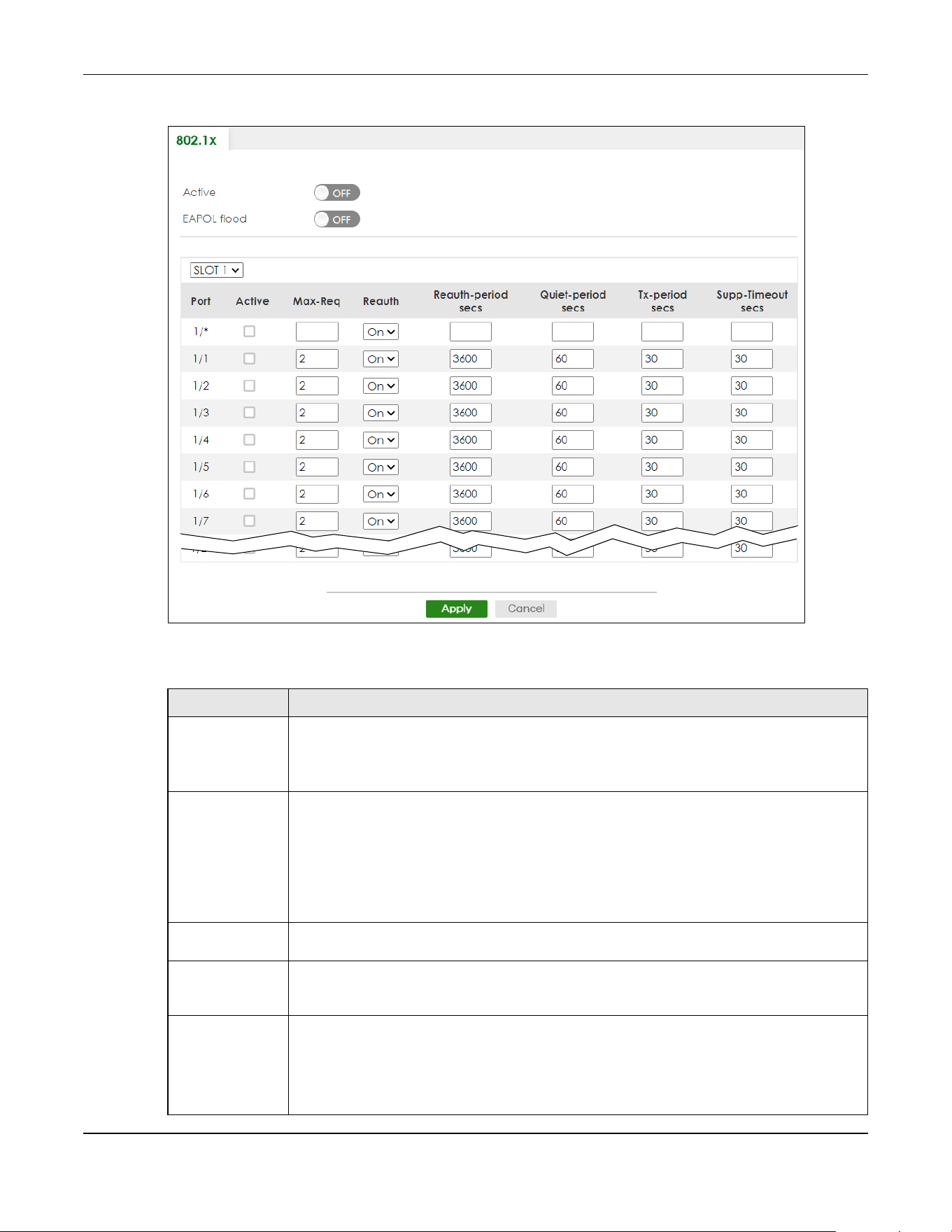
Chapter 77 Port Authentication
XGS2220 Series User’s Guide
587
Figure 471 SECURITY > Port Authentication > 802.1x (Stacking Mode)
The following table describes the labels in this screen.
Table 310 SECURITY > Port Authentication > 802.1x
LABEL DESCRIPTION
Active Enable the switch button to permit 802.1x authentication on the Switch.
Note: You must first enable 802.1x authentication on the Switch before configuring it
on each port.
EAPOL flood Enable the switch button to flood EAPOL packets to all ports in the same VLAN.
EAP over LAN (EAPOL) is a port authentication protocol used in IEEE 802.1x. It is used to
encapsulate and transmit EAP packets between the supplicant (a client device that requests
access to the network resources or services) and authenticator (the Switch) directly over the
LAN.
Note: EAPOL flood will not take effect when 802.1x authentication is enabled.
SLOT This field appears only in Stacking mode. Click the drop-down list to choose the slot number of
the Switch in a stack.
Port This field displays the port number. In Stacking mode, the first number represents the slot ID and
the second is the port number. Please note that the default stacking ports (the last four ports of
your Switch) cannot be configured. They are reserved for stacking only.
* Settings in this row apply to all ports.
Use this row only if you want to make some settings the same for all ports. Use this row first to set
the common settings and then make adjustments on a port-by-port basis.
Note: Changes in this row are copied to all the ports as soon as you make them.

Chapter 77 Port Authentication
XGS2220 Series User’s Guide
588
77.3 Activate MAC Authentication
Use this screen to activate MAC authentication. Click SECURITY > Port Authentication > MAC
Authentication to display the configuration screen as shown.
Active Select this to permit 802.1x authentication on this port. You must first allow 802.1x
authentication on the Switch before configuring it on each port.
Max-Req Specify the number of times the Switch tries to authenticate clients before sending
unresponsive ports to the Guest VLAN.
This is set to 2 by default. That is, the Switch attempts to authenticate a client twice. If the client
does not respond to the first authentication request, the Switch tries again. If the client still does
not respond to the second request, the Switch sends the client to the Guest VLAN. The client
needs to send a new request to be authenticated by the Switch again.
Reauth Specify if a subscriber has to periodically re-enter his or her user name and password to stay
connected to the port.
Reauth-period
secs
Specify the length of time required to pass before a client has to re-enter his or her user name
and password to stay connected to the port.
Quiet-period secs Specify the number of seconds the port remains in the HELD state and rejects further
authentication requests from the connected client after a failed authentication exchange.
Tx-period secs Specify the number of seconds the Switch waits for client’s response before re-sending an
identity request to the client.
Supp-Timeout
secs
Specify the number of seconds the Switch waits for client’s response to a challenge request
before sending another request.
Apply Click Apply to save your changes to the Switch’s run-time memory. The Switch loses these
changes if it is turned off or loses power, so use the Save link on the top navigation panel to
save your changes to the non-volatile memory when you are done configuring.
Cancel Click Cancel to begin configuring this screen afresh.
Table 310 SECURITY > Port Authentication > 802.1x (continued)
LABEL DESCRIPTION
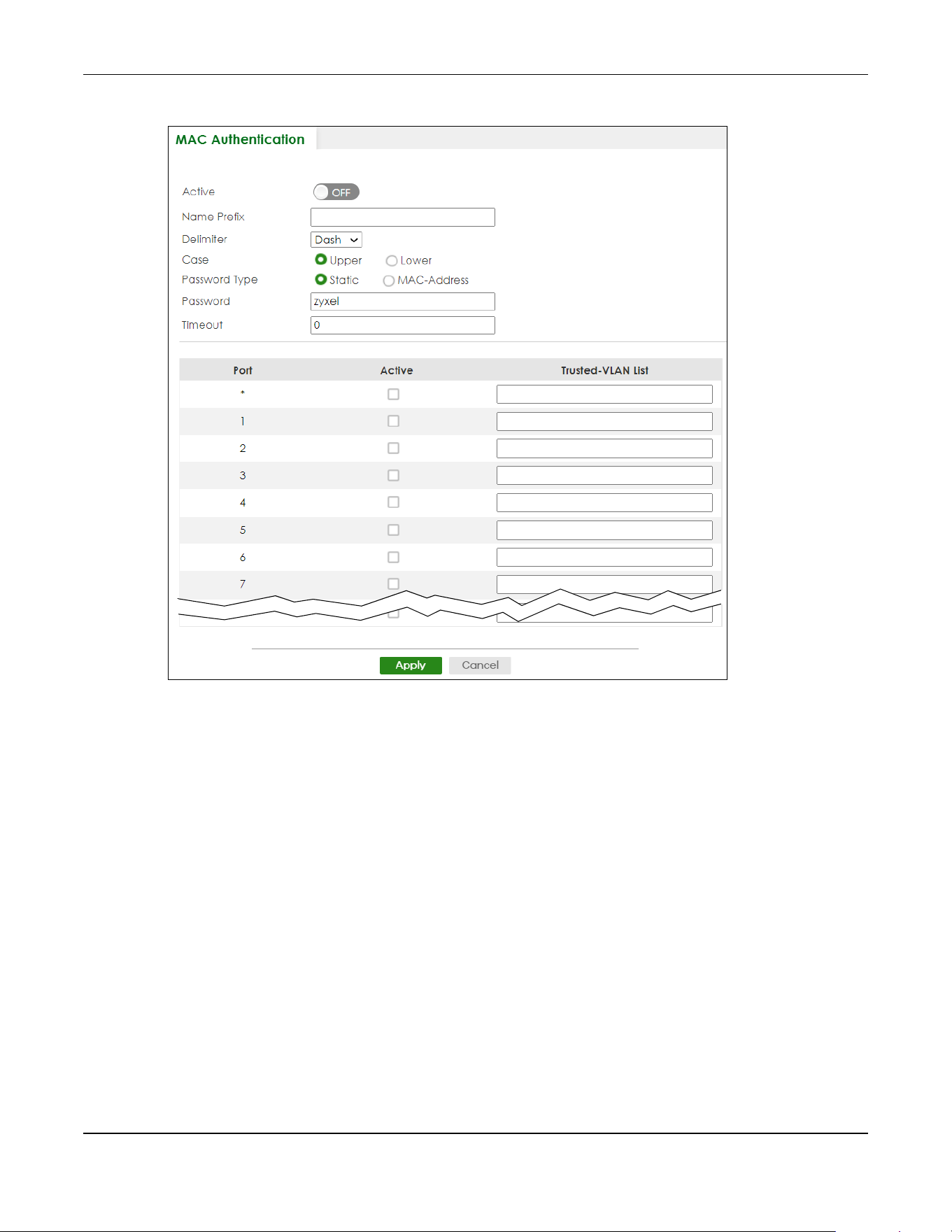
Chapter 77 Port Authentication
XGS2220 Series User’s Guide
589
Figure 472 SECURITY > Port Authentication > MAC Authentication (Standalone Mode)
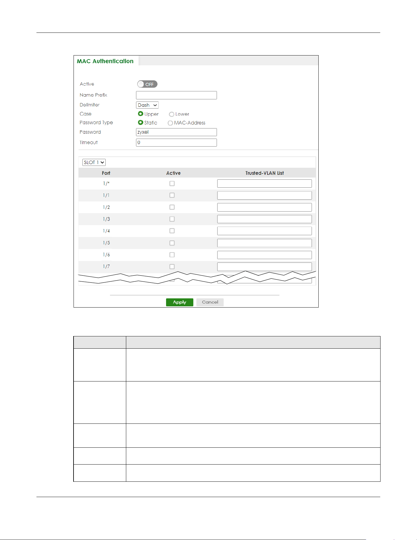
Chapter 77 Port Authentication
XGS2220 Series User’s Guide
590
Figure 473 SECURITY > Port Authentication > MAC Authentication (Stacking Mode)
The following table describes the labels in this screen.
Table 311 SECURITY > Port Authentication > MAC Authentication
LABEL DESCRIPTION
Active Enable the switch button to permit MAC authentication on the Switch.
Note: You must first enable MAC authentication on the Switch before configuring it
on each port.
Name Prefix Type the prefix that is appended to all MAC addresses sent to the RADIUS server for
authentication. You can enter up to 32 printable ASCII characters except [ ? ], [ | ], [ ' ], [ " ] or
[ , ].
If you leave this field blank, then only the MAC address of the client is forwarded to the RADIUS
server.
Delimiter Select the delimiter the RADIUS server uses to separate the pairs in MAC addresses used as the
account user name (and password). You can select Dash (–), Colon (:), or None to use no
delimiters at all in the MAC address.
Case Select the case (Upper or Lower) the RADIUS server requires for letters in MAC addresses used
as the account user name (and password).
Password Type Select Static to have the Switch send the password you specify below or MAC-Address to use
the client MAC address as the password.

Chapter 77 Port Authentication
XGS2220 Series User’s Guide
591
77.4 Guest VLAN
When 802.1x or MAC Authentication is enabled on the Switch and its ports, clients that do not have the
correct credentials are blocked from using the ports. You can configure your Switch to have one VLAN
that acts as a guest VLAN. If you enable the guest VLAN (102 in the example) on a port (2 in the
example), the user (A in the example) that is not IEEE 802.1x capable or fails to enter the correct user
name and password can still access the port, but traffic from the user is forwarded to the guest VLAN.
That is, unauthenticated users can have access to limited network resources in the same guest VLAN,
such as the Internet. The access granted to the Guest VLAN depends on how the network administrator
configures switches or routers with the guest network feature.
Password Type the password the Switch sends along with the MAC address of a client for authentication
with the RADIUS server. You can enter up to 32 printable ASCII characters except [ ? ], [ | ], [ ' ],
[ " ] or [ , ].
Timeout Specify the amount of time before the Switch allows a client MAC address that fails
authentication to try and authenticate again. Maximum time is 3000 seconds.
When a client fails MAC authentication, its MAC address is learned by the MAC address table
with a status of denied. The timeout period you specify here is the time the MAC address entry
stays in the MAC address table until it is cleared. If you specify 0 for the timeout value, the
Switch uses the Aging Time configured in the SYSTEM > Switch Setup screen.
Note: If the Aging Time in the SYSTEM > Switch Setup screen is set to a lower value,
then it supersedes this setting.
SLOT This field appears only in Stacking mode. Click the drop-down list to choose the slot number of
the Switch in a stack.
Port This field displays the port number. In Stacking mode, the first number represents the slot ID and
the second is the port number. Please note that the default stacking ports (the last four ports of
your Switch) cannot be configured. They are reserved for stacking only.
* Use this row to make the setting the same for all ports. Use this row first and then make
adjustments on a port-by-port basis.
Note: Changes in this row are copied to all the ports as soon as you make them.
Active Select this check box to permit MAC authentication on this port. You must first allow MAC
authentication on the Switch before configuring it on each port.
Trusted-VLAN List Enter the ID numbers of the trusted VLANs (separated by a comma). If a client’s VLAN ID is
specified here, the client can access the port and the connected networks without MAC
authentication.
Apply Click Apply to save your changes to the Switch’s run-time memory. The Switch loses these
changes if it is turned off or loses power, so use the Save link on the top navigation panel to
save your changes to the non-volatile memory when you are done configuring.
Cancel Click Cancel to begin configuring this screen afresh.
Table 311 SECURITY > Port Authentication > MAC Authentication (continued)
LABEL DESCRIPTION
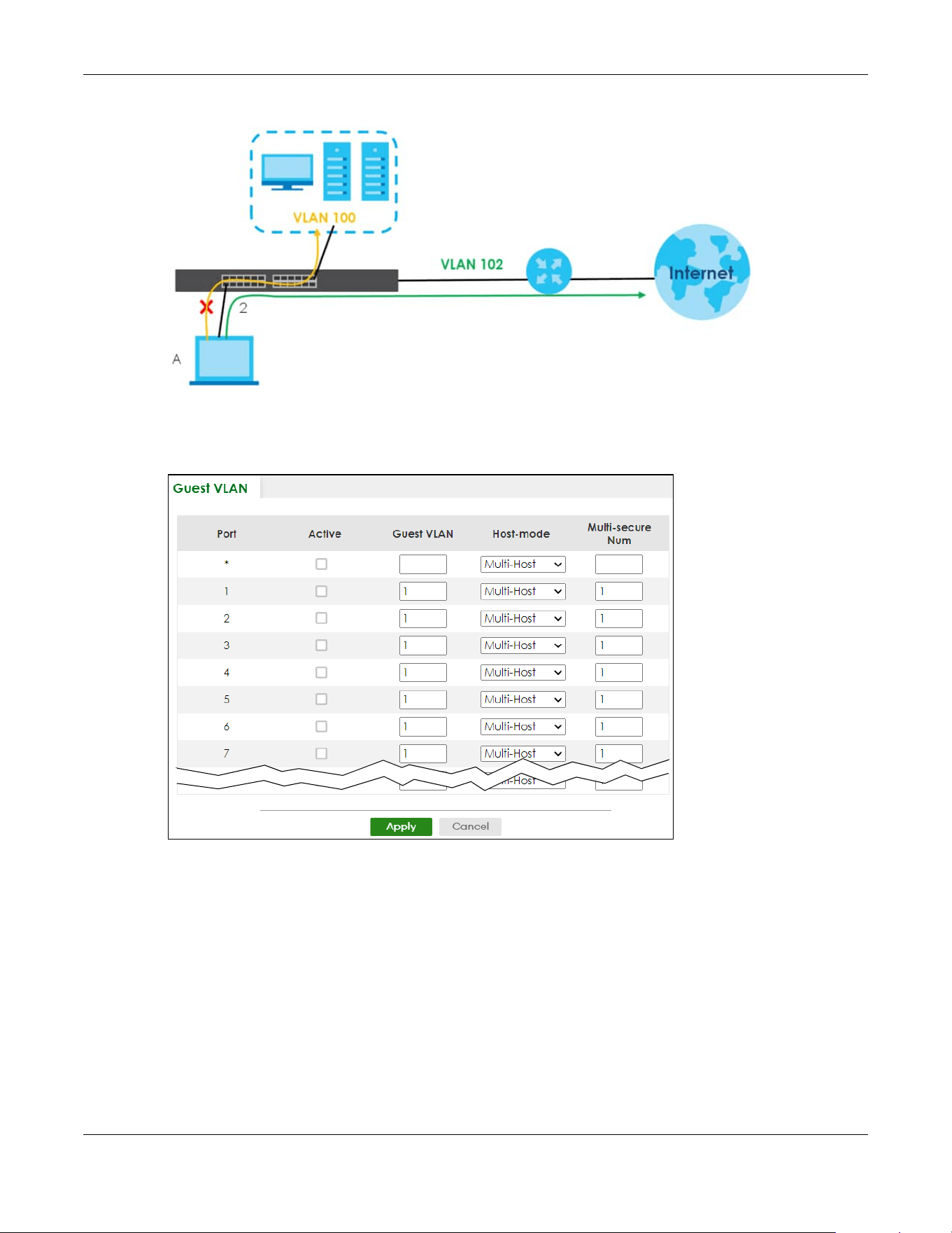
Chapter 77 Port Authentication
XGS2220 Series User’s Guide
592
Figure 474 Guest VLAN Example
Use this screen to enable and assign a guest VLAN to a port. Click SECURITY > Port Authentication >
Guest VLAN to display the configuration screen as shown.
Figure 475 SECURITY > Port Authentication > Guest VLAN (Standalone Mode)
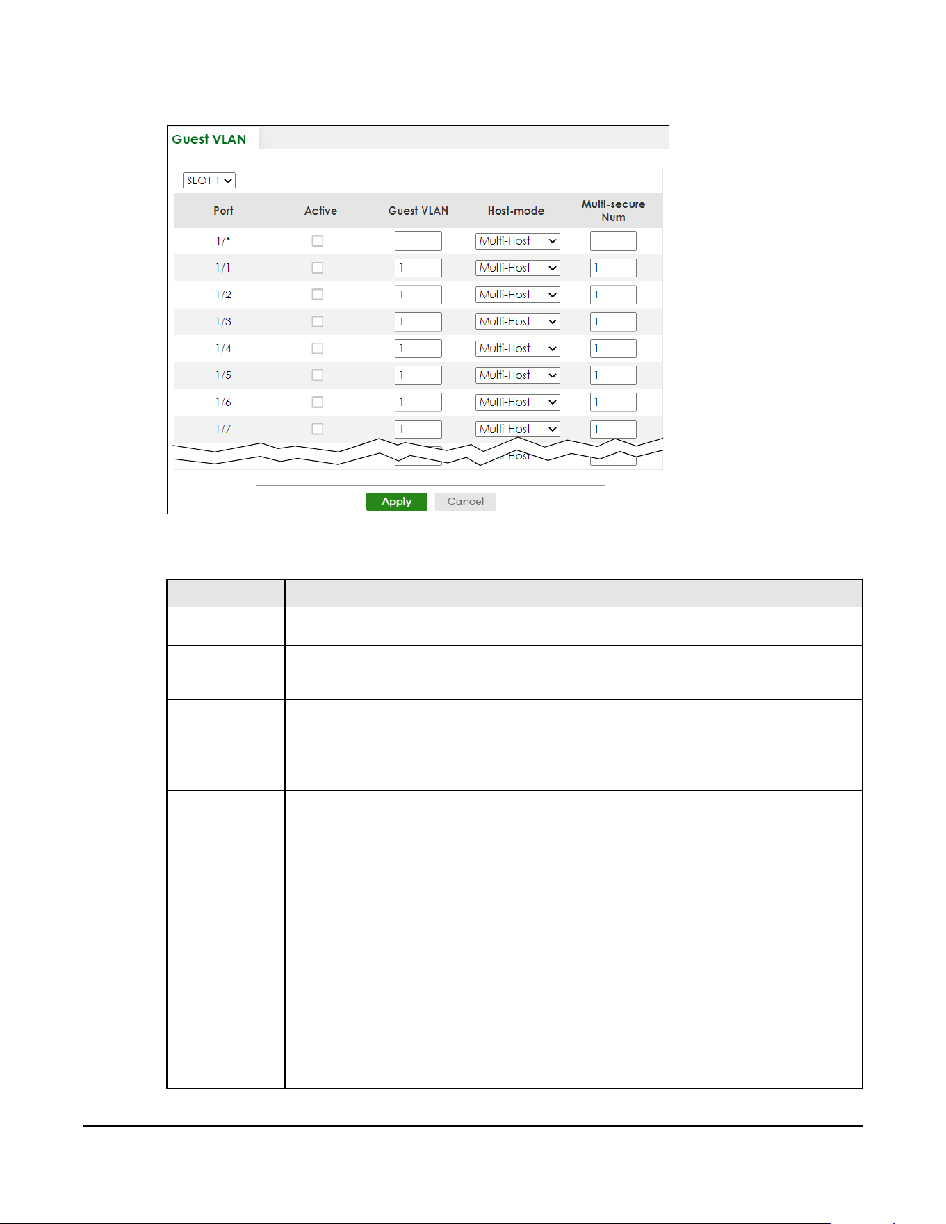
Chapter 77 Port Authentication
XGS2220 Series User’s Guide
593
Figure 476 SECURITY > Port Authentication > Guest VLAN (Stacking Mode)
The following table describes the labels in this screen.
Table 312 SECURITY > Port Authentication > Guest VLAN
LABEL DESCRIPTION
SLOT This field appears only in Stacking mode. Click the drop-down list to choose the slot number of
the Switch in a stack.
Port This field displays the port number. In Stacking mode, the first number represents the slot ID and
the second is the port number. Please note that the default stacking ports (the last four ports of
your Switch) cannot be configured. They are reserved for stacking only.
* Settings in this row apply to all ports.
Use this row only if you want to make some settings the same for all ports. Use this row first to set
the common settings and then make adjustments on a port-by-port basis.
Changes in this row are copied to all the ports as soon as you make them.
Active Select this check box to enable the guest VLAN feature on this port.
Clients that fail authentication are placed in the guest VLAN and can receive limited services.
Guest VLAN A guest VLAN is a pre-configured VLAN on the Switch that allows non-authenticated users to
access limited network resources through the Switch. You must also enable IEEE 802.1x
authentication on the Switch and the associated ports. Enter the number that identifies the
guest VLAN.
Make sure this is a VLAN recognized in your network.
Host-mode Specify how the Switch authenticates users when more than one user connect to the port
(using a hub).
Select Multi-Host to authenticate only the first user that connects to this port. If the first user
enters the correct credential, any other users are allowed to access the port without
authentication. If the first user fails to enter the correct credential, they are all put in the guest
VLAN. Once the first user who did authentication logs out or disconnects from the port, the rest
of the users are blocked until a user does the authentication process again.
Select Multi-Secure to authenticate each user that connects to this port.
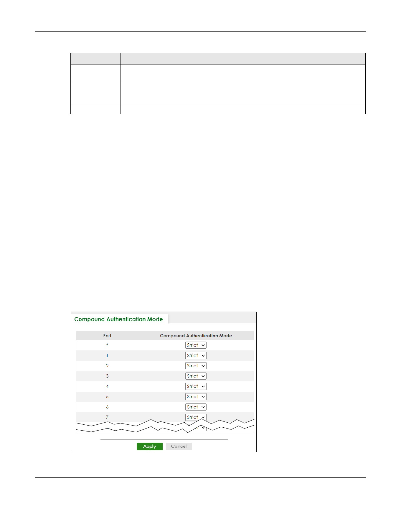
Chapter 77 Port Authentication
XGS2220 Series User’s Guide
594
77.5 Compound Authentication
Use this screen to allow network access for clients that:
• pass either IEEE 802.1x authentication OR MAC authentication, or
• pass both IEEE 802.1x authentication AND MAC authentication.
The authentication modes are:
• In IEEE 802.1x authentication, the Switch prompts the client for login information in the form of a user
name and password. When the client provides the login credentials, the Switch sends an
authentication request to a RADIUS server. The RADIUS server validates whether this client is allowed
access to the port. Use the SECURITY > AAA > RADIUS Server Setup screen to configure the RADIUS
server.
• In MAC authentication, the login credentials are based on the source MAC address of the client
connecting to a port on the Switch along with a password configured specifically for MAC
authentication on the Switch.
Click SECURITY > Port Authentication > Compound Authentication Mode to display the configuration
screen as shown.
Figure 477 SECURITY > Port Authentication > Compound Authentication Mode (Standalone Mode)
Multi-secure Num If you set Host-mode to Multi-Secure, specify the maximum number of users (between 1 and
24) that the Switch will authenticate on this port.
Apply Click Apply to save your changes to the Switch’s run-time memory. The Switch loses these
changes if it is turned off or loses power, so use the Save link on the top navigation panel to
save your changes to the non-volatile memory when you are done configuring.
Cancel Click Cancel to begin configuring this screen afresh.
Table 312 SECURITY > Port Authentication > Guest VLAN (continued)
LABEL DESCRIPTION

Chapter 77 Port Authentication
XGS2220 Series User’s Guide
595
Figure 478 SECURITY > Port Authentication > Compound Authentication Mode (Stacking Mode)
The following table describes the labels in this screen.
77.6 Technical Reference
This section provides technical background information on the topics discussed in this chapter.
Table 313 SECURITY > Port Authentication > Compound Authentication Mode
LABEL DESCRIPTION
SLOT This field appears only in Stacking mode. Click the drop-down list to choose the slot number of
the Switch in a stack.
Port This field displays the port number. In Stacking mode, the first number represents the slot ID and
the second is the port number. Please note that the default stacking ports (the last four ports of
your Switch) cannot be configured. They are reserved for stacking only.
* Settings in this row apply to all ports.
Use this row only if you want to make some settings the same for all ports. Use this row first to set
the common settings and then make adjustments on a port-by-port basis.
Changes in this row are copied to all the ports as soon as you make them.
Compound
Authentication
Mode
Specify how the Switch authenticates clients for network access.
Select Strict to allow network access to clients only when clients passes IEEE 802.1x
authentication AND MAC authentication at the same time.
Select Loose to allow network access to clients when clients passes IEEE 802.1x authentication
OR MAC authentication.
Apply Click Apply to save your changes to the Switch’s run-time memory. The Switch loses these
changes if it is turned off or loses power, so use the Save link on the top navigation panel to
save your changes to the non-volatile memory when you are done configuring.
Cancel Click Cancel to begin configuring this screen afresh.

Chapter 77 Port Authentication
XGS2220 Series User’s Guide
596
77.6.1 IEEE 802.1x
The IEEE 802.1x is a standard for authentication as well as providing additional accounting and control
features. It can be implemented both on wired and wireless networks. It is supported by Windows XP and
a number of network devices. Some advantages of IEEE 802.1x are:
• User based identification
• Support for RADIUS (Remote Authentication Dial In User Service, RFC 2138, 2139) for centralized user
profile and accounting management on a network RADIUS server.
• Support for EAP (Extensible Authentication Protocol, RFC 2486) that allows additional authentication
methods to be deployed with no changes to the switch or the wired clients.
77.6.2 RADIUS
RADIUS is based on a client-server model that supports authentication, authorization and accounting.
The RADIUS server handles the following tasks:
• Authentication
Determines the identity of the users.
•Authorization
Determines the network services available to authenticated users once they are connected to the
network.
• Accounting
Keeps track of the actions that are perform on the switch, such as login events.
RADIUS is a simple package exchange in which your switch acts as a message relay between the wired
client and the network RADIUS server.
77.6.2.1 Types of RADIUS Messages
The following types of RADIUS messages are exchanged between the switch and the RADIUS server for
user authentication:
• Access-Request
Sent by a switch requesting authentication.
• Access-Reject
Sent by a RADIUS server rejecting access.
• Access-Accept
Sent by a RADIUS server allowing access.
• Access-Challenge
Sent by a RADIUS server requesting more information in order to allow access. The switch sends a proper
response from the user and then sends another Access-Request message.

Chapter 77 Port Authentication
XGS2220 Series User’s Guide
597
The following types of RADIUS messages are exchanged between the switch and the RADIUS server for
user accounting:
• Accounting-Request
Sent by the switch requesting accounting.
• Accounting-Response
Sent by the RADIUS server to indicate that it has started or stopped accounting.
The switch and the RADIUS server use a shared secret key, which is a password, they both know to
authenticate the communications between them, and ensure network security. A shared key is not sent
over the network.
The switch forwards the RADIUS requests of a client to the RADIUS server. The login password information
exchanged is sent over the network and encrypted to protect the network from unauthorized access.
77.6.3 EAP (Extensible Authentication Protocol) Authentication
This section discusses some popular authentication types: EAP-MD5, EAP-TLS, EAP-TTLS, PEAP and LEAP.
Your wired LAN device may not support all authentication types.
EAP (Extensible Authentication Protocol) is an authentication protocol that runs on top of the IEEE 802.1x
transport mechanism in order to support multiple types of user authentication. By using EAP to interact
with an EAP-compatible RADIUS server, a switch helps a wired station and a RADIUS server perform
authentication.
The type of authentication you use depends on the RADIUS server and an intermediary switch that
supports IEEE 802.1x.
For EAP-TLS authentication type, you must first have a wired connection to the network and obtain the
certificates from a certificate authority (CA). A certificate (also called digital IDs) can be used to
authenticate users and a CA issues certificates and guarantees the identity of each certificate owner.
• EAP-MD5 (Message-Digest Algorithm 5)
MD5 authentication is the simplest one-way authentication method. The authentication server sends a
challenge to the wired client. The wired client ‘proves’ that it knows the password by encrypting the
password with the challenge and sends back the information. Password is not sent in plain text.
However, MD5 authentication has some weaknesses. Since the authentication server needs to get the
plain text passwords, the passwords must be stored. Thus someone other than the authentication server
may access the password file. In addition, it is possible to impersonate an authentication server as MD5
authentication method does not perform mutual authentication. Finally, MD5 authentication method
does not support data encryption with dynamic session key. You must configure WEP encryption keys for
data encryption.
• EAP-TLS (Transport Layer Security)
With EAP-TLS, digital certifications are needed by both the server and the wired clients for mutual
authentication. The server presents a certificate to the client. After validating the identity of the server,
the client sends a different certificate to the server. The exchange of certificates is done in the open
before a secured tunnel is created. This makes user identity vulnerable to passive attacks. A digital
certificate is an electronic ID card that authenticates the sender’s identity. However, to implement

Chapter 77 Port Authentication
XGS2220 Series User’s Guide
598
EAPTLS, you need a Certificate Authority (CA) to handle certificates, which imposes a management
overhead.
• EAP-TTLS (Tunneled Transport Layer Service)
EAP-TTLS is an extension of the EAP-TLS authentication that uses certificates for only the server-side
authentications to establish a secure connection. Client authentication is then done by sending user
name and password through the secure connection, thus client identity is protected. For client
authentication, EAP-TTLS supports EAP methods and legacy authentication methods such as PAP, CHAP,
MS-CHAP and MS-CHAP v2.
•PEAP (Protected EAP)
Like EAP-TTLS, server-side certificate authentication is used to establish a secure connection, then use
simple user name and password methods through the secured connection to authenticate the clients,
thus hiding client identity. However, PEAP only supports EAP methods, such as EAP-MD5, EAP-MSCHAPv2
and EAP-GTC (EAP-Generic Token Card), for client authentication. EAP-GTC is implemented only by
Cisco.
•LEAP
LEAP (Lightweight Extensible Authentication Protocol) is a Cisco implementation of IEEE 802.1x.
77.6.4 EAPOL (EAP over LAN)
EAPOL is a port authentication protocol used in IEEE 802.1x. It encapsulates and sends EAP packets from
the LAN. EAPOL exchanges the following messages between a wired client and switch.
•EAPOL-Start
A wired client will send this message to a switch to let it know the wired client is ready.
•EAPOL-Key
The switch will send an encryption key to the wired client. It will be allowed access to the network when
both of the switch and wired client have the correct encryption keys.
•EAP-Packet
Both of the wired client and the switch will send this message to complete the authentication process.
• EAPOL-Logoff
This message will be sent when the wired client wants to be disconnected from the network.
• EAPOL-Encapsulated-ASF-Alert
This message is sent If the authentication process is not completed yet, and alerts needs to be
forwarded.

Chapter 78 Port Security
XGS2220 Series User’s Guide
599
CHAPTER 78
Port Security
78.1 Port Security Overview
This chapter shows you how to set up port security.
78.2 About Port Security
Port security allows only packets with dynamically learned MAC addresses and/or configured static
MAC addresses to pass through a port on the Switch. The Switch can learn up to 32K 8k MAC addresses
in total with no limit on individual ports other than the sum cannot exceed 32K 8k.
For maximum port security, enable this feature, disable MAC address learning and configure static MAC
addresses for a port. It is not recommended you disable port security together with MAC address
learning as this will result in many broadcasts. By default, MAC address learning is still enabled even
though the port security is not activated.
78.3 Port Security Setup
Click SECURITY > Port Security in the navigation panel to display the screen as shown.
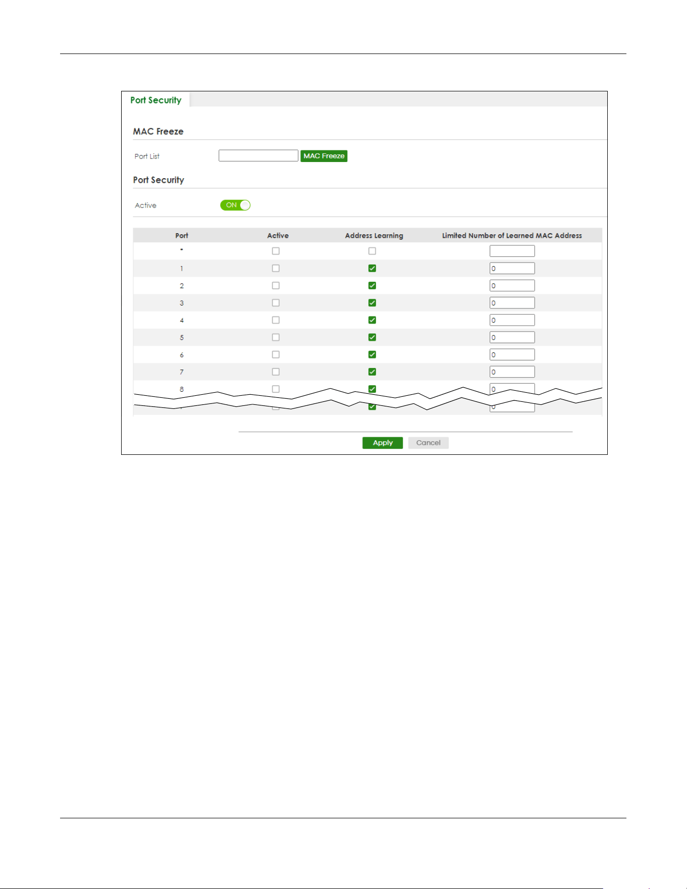
Chapter 78 Port Security
XGS2220 Series User’s Guide
600
Figure 479 SECURITY > Port Security (Standalone Mode)

Chapter 78 Port Security
XGS2220 Series User’s Guide
601
Figure 480 SECURITY > Port Security (Stacking Mode)
The following table describes the labels in this screen.
Table 314 SECURITY > Port Security
LABEL DESCRIPTION
Port List Enter the number of the ports (separated by a comma) on which you want to enable port
security and disable MAC address learning. In Stacking mode, the first number represents the
slot and the second the port number. Enter 1/1-1/24,2/23 for ports 1 to 24 for the Switch in slot 1
and port 23 for the Switch in slot 2, for example. After you click MAC Freeze, all previously
learned MAC addresses on the specified ports will become static MAC addresses and display
in the SWITCHING > Static MAC Forwarding screen.
MAC Freeze Click MAC Freeze to have the Switch automatically select the Active check boxes and clear
the Address Learning check boxes only for the ports specified in the Port List.
Port Security
Active Enable the switch button to enable port security on the Switch.
SLOT This field appears only in Stacking mode. Click the drop-down list to choose the slot number of
the Switch in a stack.
Port This field displays the port number. In Stacking mode, the first number represents the slot ID and
the second is the port number. Please note that the default stacking ports (the last four ports of
your Switch) cannot be configured. They are reserved for stacking only.
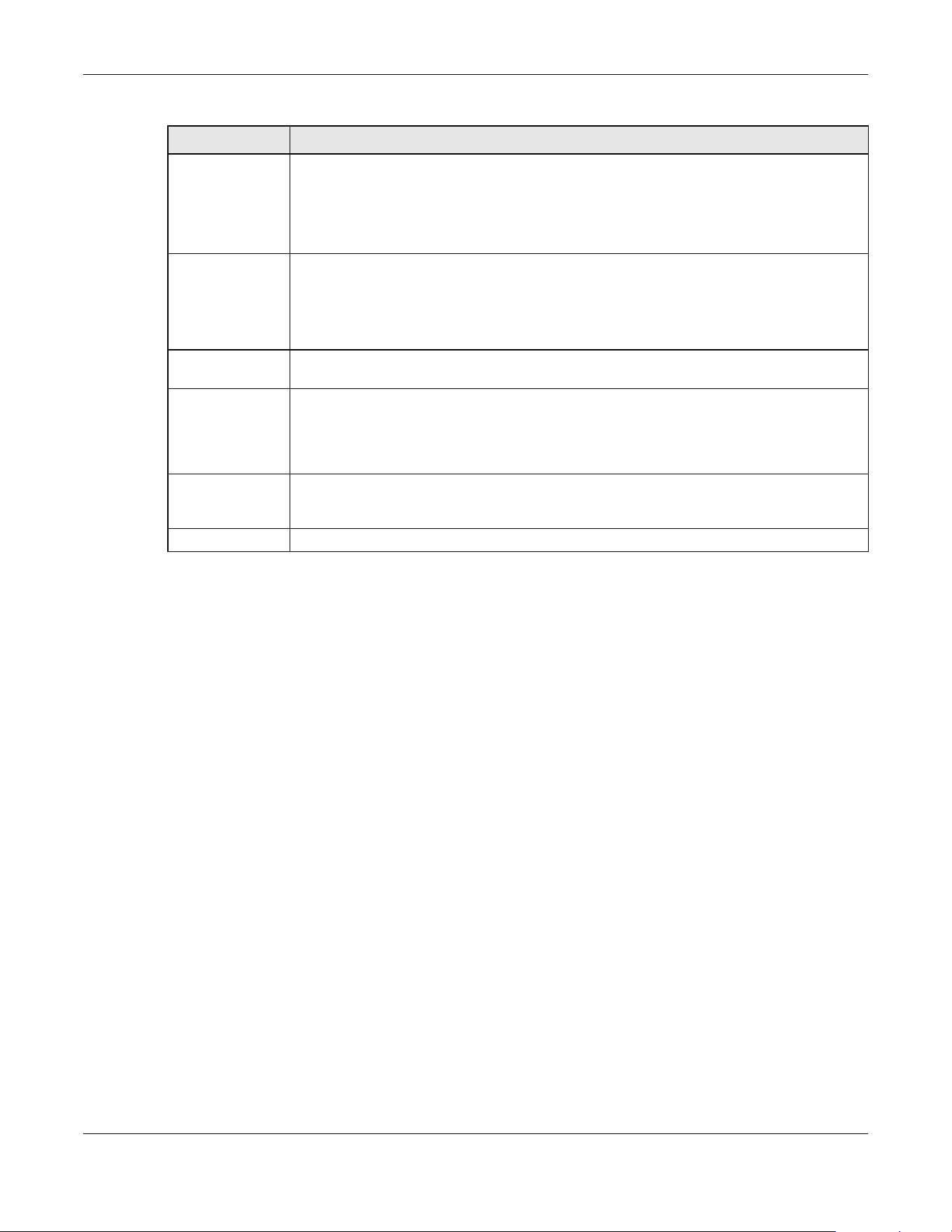
Chapter 78 Port Security
XGS2220 Series User’s Guide
602
* Settings in this row apply to all ports.
Use this row only if you want to make some of the settings the same for all ports. Use this row first
to set the common settings and then make adjustments on a port-by-port basis.
Note: Changes in this row are copied to all the ports as soon as you make them.
Active Select this check box to enable the port security feature on this port. The Switch forwards
packets whose MAC addresses is in the MAC address table on this port. Packets with no
matching MAC addresses are dropped.
Clear this check box to disable the port security feature. The Switch forwards all packets on this
port.
Address
Learning
MAC address learning reduces outgoing broadcast traffic. For MAC address learning to occur
on a port, the port itself must be active with address learning enabled.
Limited
Number of
Learned MAC
Address
Use this field to limit the number of (dynamic) MAC addresses that may be learned on a port.
For example, if you set this field to "5" on port 2, then only the devices with these five learned
MAC addresses may access port 2 at any one time. A sixth device must wait until one of the
five learned MAC addresses ages out. MAC address aging out time can be set in the SYSTEM >
Switch Setup screen. The valid range is from “0” to “32K”. “0” means this feature is disabled.
Apply Click Apply to save your changes to the Switch’s run-time memory. The Switch loses these
changes if it is turned off or loses power, so use the Save link on the top navigation panel to
save your changes to the non-volatile memory when you are done configuring.
Cancel Click Cancel to begin configuring this screen afresh.
Table 314 SECURITY > Port Security (continued)
LABEL DESCRIPTION

XGS2220 Series User’s Guide
603
CHAPTER 79
MAINTENANCE
79.1 Overview
This chapter explains how to configure the screens that let you maintain the firmware and configuration
files.
79.1.1 What You Can Do
• Use the Certificates screen (Section 79.2 on page 603) to see the Certificates screen and import the
Switch's CA-signed certificates.
• Use the Cluster Management screens (Section 79.5 on page 608) to manage the switches within a
cluster and view cluster status.
• Use the Restore Configuration screen (Section 79.8 on page 613) to upload a stored device
configuration file.
• Use the Backup Configuration screen (Section 79.9 on page 613) to save your configurations for later
use.
• Use the Auto Configuration screen (Section 79.10 on page 614) to overwrite the running configuration
stored in the Switch’s RAM.
• Use the Erase Running-Configuration screen (Section 79.11 on page 615) to reset the configuration to
the Zyxel default configuration settings.
• Use the Save Configuration screen (Section 79.12 on page 616) to save the current configuration
settings to a specific configuration file on the Switch.
• Use the Configure Clone screen (Section 79.13 on page 617) to copy the basic and advanced
settings from a source port to a destination port or ports.
• Use the Diagnostic screen (Section 79.14 on page 619) to ping IP addresses, run a traceroute, perform
port tests or show the Switch’s location between devices.
• Use the Firmware Upgrade screen (Section 79.15 on page 622) to upload the latest firmware.
• Use the Reboot System screen (Section 79.16 on page 625) to restart the Switch without physically
turning the power off and load a specific configuration file.
• Use the Tech-Support screen (Section 79.17 on page 627) to create reports for customer support if
there are problems with the Switch.
79.2 Certificates
The Switch can use HTTPS certificates that are verified by a third party to create secure HTTPS
connections between your computer and the Switch. This way, you may securely access the Switch
using the Web Configurator. See Section 67.5.2 on page 505 for more information about HTTPS.
Certificates are based on public-private key pairs. A certificate contains the certificate owner’s identity
and public key. Certificates provide a way to exchange public keys for use in authentication.

Chapter 79 MAINTENANCE
XGS2220 Series User’s Guide
604
Click MAINTENANCE > Certificates to open the following screen. Use this screen to import the Switch's
CA-signed certificates.
Figure 481 MAINTENANCE > Certificates
The following table describes the labels in this screen.
Table 315 MAINTENANCE > Certificates
LABEL DESCRIPTION
File Path Click Choose File or Browse to find the certificate file you want to upload.
Password Enter the certificate file’s password that was created when the PKCS #12 file was exported.
The password consists of up to 32 printable ASCII characters except [ ? ], [ | ], [ ' ], [ " ] or [ ,
].
Import Click this button to save the certificate that you have enrolled from a certification authority
from your computer to the Switch.
Synchronize
Certificate
Note: This part only appears in Stacking mode.
Active Enable this option to allow the master Switch in Stacking mode to synchronize CA-signed
certificates to all stacking members and save it to their non-volatile memory.
Or, delete the stacking members’ CA-signed certificate if a CA-signed certificate does not
exist in the master Switch.
Otherwise, disable this option.
Apply Click Apply to save your changes to the Switch’s run-time memory. The Switch loses these
changes if it is turned off or loses power, so use the Save link on the top navigation panel to
save your changes to the non-volatile memory when you are done configuring.
Cancel Click Cancel to begin configuring this screen afresh.
Service This field displays the service type that this certificate is for.
Subject This field displays identifying information about the certificate’s owner, such as CN
(Common Name), OU (Organizational Unit or department), O (Organization or company)
and C (Country). It is recommended that each certificate have unique subject
information.
Issuer This field displays identifying information about the certificate’s issuing certification
authority, such as a common name, organizational unit or department, organization or
company and country.
Valid From This field displays the date that the certificate becomes applicable.
Valid To This field displays the date that the certificate expires.
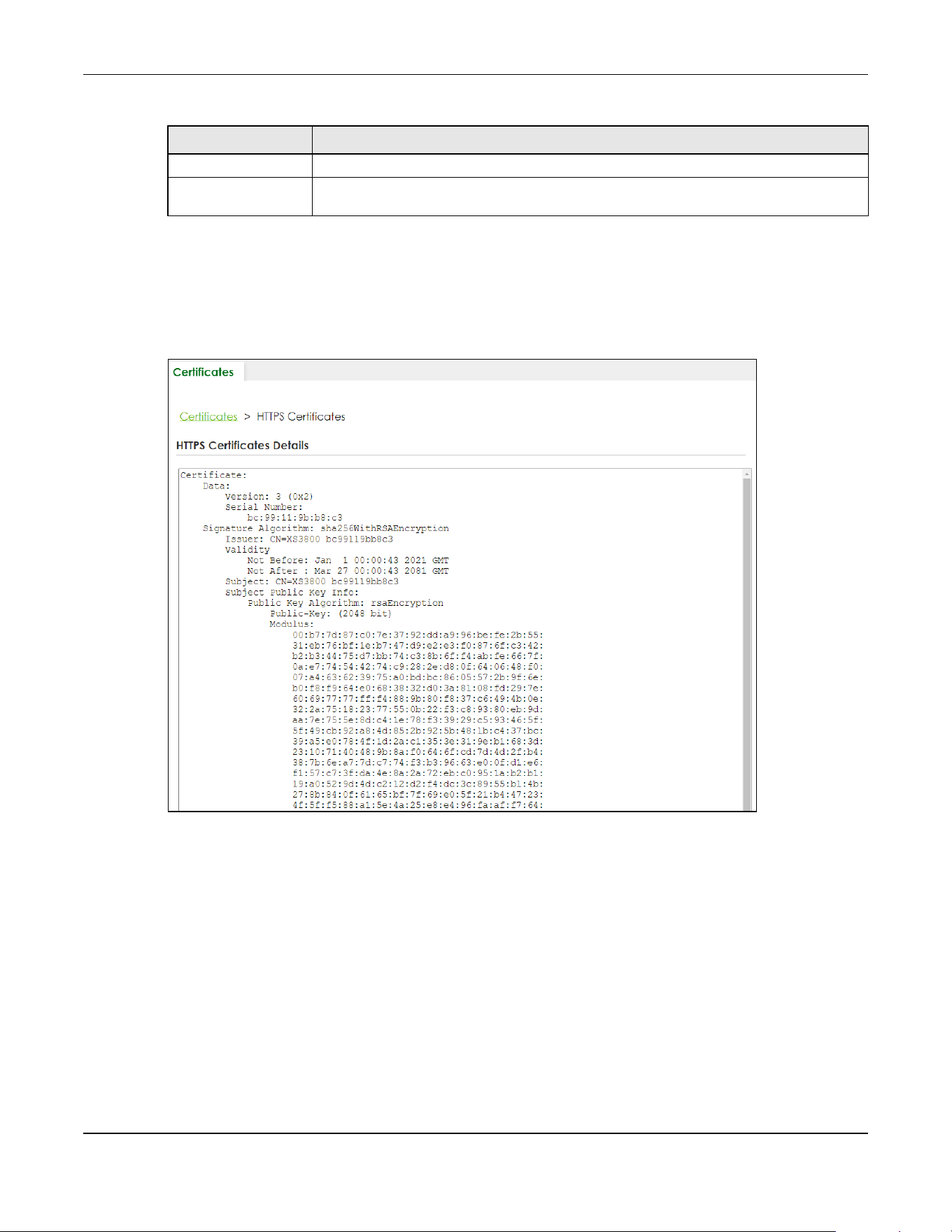
Chapter 79 MAINTENANCE
XGS2220 Series User’s Guide
605
79.2.1 HTTPS Certificates
Use this screen to view the HTTPS certificate details. Click a hyperlink in the Service column in the
MAINTENANCE > Certificates screen to open the following screen.
Figure 482 MAINTENANCE > Certificates > HTTPS
79.3 Technical Reference
This section provides technical background information on the topics discussed in this chapter.
79.3.1 FTP Command Line
This section shows some examples of uploading to or downloading files from the Switch using FTP
commands. First, understand the filename conventions.
Select an entry’s check box to select a specific entry.
Delete Click this button to delete the certificate (or certification request). You cannot delete a
certificate that one or more features is configured to use.
Table 315 MAINTENANCE > Certificates (continued)
LABEL DESCRIPTION

Chapter 79 MAINTENANCE
XGS2220 Series User’s Guide
606
79.3.2 Filename Conventions
The configuration file (also known as the romfile or ROM) contains the Zyxel factory default configuration
settings in the screens such as password, Switch setup, IP Setup, and so on. Once you have customized
the Switch’s settings, they can be saved back to your computer under a filename of your choosing.
ZyNOS (Zyxel Network Operating System sometimes referred to as the “ras” file) is the system firmware
and has a “bin” filename extension.
You can store up to two images, or firmware files of the same device model, on the Switch. Only one
image is used at a time.
•Run the boot image <1|2> command to specify which image is updated when firmware is loaded
using the Web Configurator and to specify which image is loaded when the Switch starts up.
• You can also use FTP commands to upload firmware to any image.
The Switch supports dual firmware images, ras-0 and ras-1. You can switch from one to the other by
using the boot image <index> command, where <index> is 1 (ras-0) or 2 (ras-1). See the CLI
Reference Guide for more information about using commands. The system does not reboot after it
switches from one image to the other.
79.3.2.1 Example FTP Commands
ftp> put firmware.bin ras-0
This is a sample FTP session showing the transfer of the computer file "firmware.bin" to the Switch’s
Firmware 1.
ftp> get config1 config1.cfg
This is a sample FTP session saving the Switch’s configuration file 1 (Config1) to a file called “config1.cfg”
on your computer.
If your (T)FTP client does not allow you to have a destination filename different than the source, you will
need to rename them as the Switch only recognizes “config” and “ras”. Be sure you keep unaltered
copies of both files for later use.
Be sure to upload the correct model firmware as uploading the wrong
model firmware may damage your device.
Table 316 Filename Conventions
FILE TYPE INTERNAL NAME EXTERNAL NAME DESCRIPTION
Configuration File config1
config2
*.cfg This is the configuration filename on the
Switch. Uploading the config file replaces
the specified configuration file system,
including your Switch configurations,
system-related data (including the default
password), the error log and the trace log.
Firmware ras *.bin This is the generic name for the ZyNOS
firmware on the Switch.
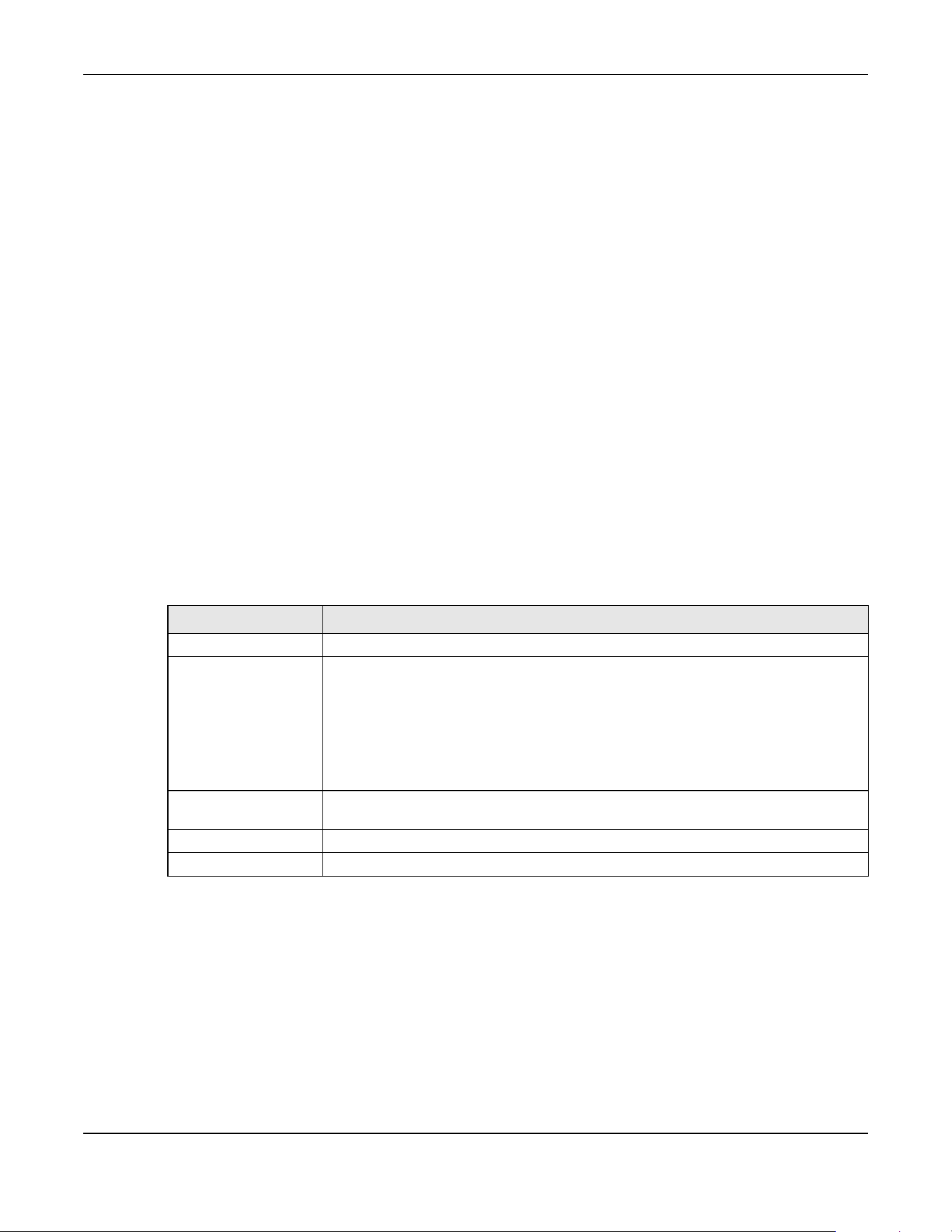
Chapter 79 MAINTENANCE
XGS2220 Series User’s Guide
607
79.3.3 FTP Command Line Procedure
1 Launch the FTP client on your computer.
2 Enter open, followed by a space and the IP address of your Switch.
3 Press [ENTER] when prompted for a user name.
4 Enter your password as requested (the default is “1234”).
5 Enter bin to set transfer mode to binary.
6 Use put to transfer files from the computer to the Switch, for example, put firmware.bin ras transfers
the firmware on your computer (firmware.bin) to the Switch and renames it to “ras”. Similarly, put
config.cfg config1 transfers the configuration file on your computer (config.cfg) to the Switch and
renames it to “config1”. Likewise get config1 config.cfg transfers the configuration file on the Switch
to your computer and renames it to “config.cfg”. See Table 316 on page 606 for more information on
filename conventions.
7 Enter quit to exit the ftp prompt.
79.3.4 GUI-based FTP Clients
The following table describes some of the commands that you may see in GUI-based FTP clients.
79.3.5 FTP Restrictions
FTP will not work when:
• FTP service is disabled in the SECURITY > Access Control > Service Access Control screen.
• The IP addresses in the SECURITY > Access Control > Remote Management screen does not match the
client IP address. If it does not match, the Switch will disconnect the FTP session immediately.
Table 317 General Commands for GUI-based FTP Clients
COMMAND DESCRIPTION
Host Address Enter the address of the host server.
Login Type Anonymous.
This is when a user I.D. and password is automatically supplied to the server for
anonymous access. Anonymous logins will work only if your ISP or service administrator
has enabled this option.
Normal.
The server requires a unique User ID and Password to login.
Transfer Type Transfer files in either single-byte printable characters (plain text format) or in binary
mode. Configuration and firmware files should be transferred in binary mode.
Initial Remote Directory Specify the default remote directory (path).
Initial Local Directory Specify the default local directory (path).

Chapter 79 MAINTENANCE
XGS2220 Series User’s Guide
608
79.4 Cluster Management Overview
Cluster Management allows you to manage switches through one Switch, called the cluster manager.
The switches must be directly connected and be in the same VLAN group so as to be able to
communicate with one another.
In the following example, switch A in the basement is the cluster manager and the other switches on the
upper floors of the building are cluster members.
Figure 483 Clustering Application Example
79.4.1 What You Can Do
• Use the Cluster Management Status screen (Section 79.5 on page 608) to view the role of the Switch
within the cluster and to access a cluster member Switch’s Web Configurator.
• Use the Cluster Management Setup screen (Section 79.6 on page 609) to configure clustering
management.
79.5 Cluster Management Status
Use this screen to view the role of the Switch within the cluster and to access a cluster member Switch’s
Web Configurator.
Table 318 Zyxel Clustering Management Specifications
Maximum number of cluster members 24
Cluster Member Models Must be compatible with Zyxel cluster management
implementation.
Cluster Manager The Switch through which you manage the cluster member
switches.
Cluster Members The switches being managed by the cluster manager Switch.
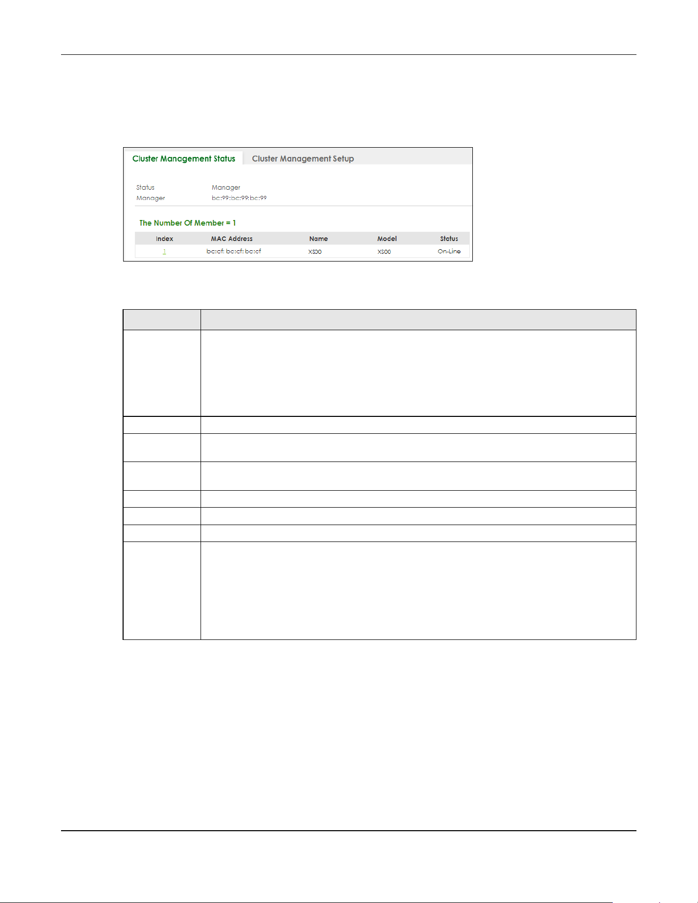
Chapter 79 MAINTENANCE
XGS2220 Series User’s Guide
609
Click MAINTENANCE > Cluster Management in the navigation panel to display the following screen.
Note: A cluster can only have one manager.
Figure 484 MAINTENANCE > Cluster Management > Cluster Management Status
The following table describes the labels in this screen.
79.6 Clustering Management Setup
Use this screen to configure clustering management. Click MAINTENANCE > Cluster Management >
Cluster Management Setup to display the next screen.
Table 319 MAINTENANCE > Cluster Management > Cluster Management Status
LABEL DESCRIPTION
Status This field displays the role of this Switch within the cluster.
Manager
Member (you see this if you access this screen in the cluster member Switch directly and not
through the cluster manager)
None (neither a manager nor a member of a cluster)
Manager This field displays the cluster manager Switch’s hardware MAC address.
The Number Of
Member
This field displays the number of switches that make up this cluster. The following fields describe
the cluster member switches.
Index You can manage cluster member switches through the cluster manager Switch. Each number in
the Index column is a hyperlink leading to the cluster member Switch’s Web Configurator.
MAC Address This is the cluster member Switch’s hardware MAC address.
Name This is the cluster member Switch’s System Name.
Model This field displays the model name.
Status This field displays:
Online (the cluster member Switch is accessible)
Error (for example the cluster member Switch password was changed or the Switch was set as
the manager and so left the member list, and so on)
Offline (the Switch is disconnected – Offline shows approximately 1.5 minutes after the link
between cluster member and manager goes down)
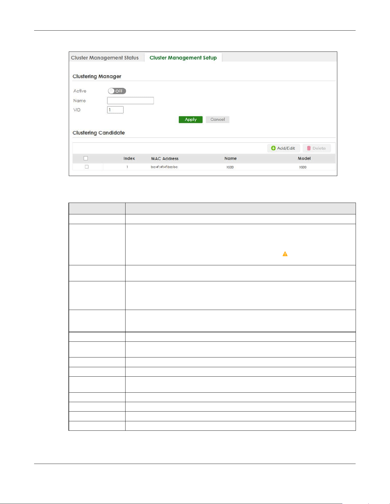
Chapter 79 MAINTENANCE
XGS2220 Series User’s Guide
610
Figure 485 MAINTENANCE > Cluster Management > Cluster Management Setup
The following table describes the labels in this screen.
Click the Add/Edit button to open the Add/Edit screen. Use this screen to configure a clustering
candidate for the Switch.
Table 320 MAINTENANCE > Cluster Management > Cluster Management Setup
LABEL DESCRIPTION
Clustering Manager The following fields relate to configuring the cluster manager.
Active Enable the switch button to have this Switch become the cluster manager switch. A cluster
can only have one manager. Other (directly connected) switches that are set to be cluster
managers will not be visible in the Clustering Candidates list. If a Switch that was previously a
cluster member is later set to become a cluster manager, then its Status is displayed as Error
in the Cluster Management Status screen and a warning icon ( ) appears in the member
summary list below.
Name Type a name to identify the Clustering Manager. You may use up to 32 printable ASCII
characters except [ ? ], [ | ], [ ' ], [ " ] or [ , ]. (spaces are allowed).
VID This is the VLAN ID and is only applicable if the Switch is set to 802.1Q VLAN. All switches must
be directly connected and in the same VLAN group to belong to the same cluster. Switches
that are not in the same VLAN group are not visible in the Clustering Candidates list. This field
is ignored if the Clustering Manager is using Port-based VLAN.
Apply Click Apply to save your changes to the Switch’s run-time memory. The Switch loses these
changes if it is turned off or loses power, so use the Save link on the top navigation panel to
save your changes to the non-volatile memory when you are done configuring.
Cancel Click Cancel to begin configuring this screen afresh.
Clustering
Candidate
The next summary table shows the information for the clustering members configured.
Add/Edit Click this button to create or configure a clustering candidate.
Delete Click this button to remove the clustering candidate.
Select an entry’s check box to select a specific entry. Otherwise, select the check box in the
table heading row to select all entries.
Index This is the index number of a cluster member switch.
MAC Address This is the cluster member switch’s hardware MAC address.
Name This is the cluster member switch’s System Name.
Model This is the cluster member switch’s model name.

Chapter 79 MAINTENANCE
XGS2220 Series User’s Guide
611
Figure 486 MAINTENANCE > Cluster Management > Cluster Management Setup > Add/Edit
The following table describes the labels in this screen.
79.7 Technical Reference
This section provides technical background information on the topics discussed in this chapter.
79.7.1 Cluster Member Switch Management
Go to the MAINTENANCE > Clustering Management > Clustering Management Status screen of the
cluster manager switch and then select an Index hyperlink from the list of members to go to that cluster
member switch's Web Configurator home page. This cluster member Web Configurator home page
and the home page that you would see if you accessed it directly are different.
Table 321 MAINTENANCE > Cluster Management > Cluster Management Setup > Add/Edit
LABEL DESCRIPTION
List A list of suitable candidates found by auto-discovery is shown here. The switches must be
directly connected. Directly connected switches that are set to be cluster managers will not
be visible in the Clustering Candidate list. Switches that are not in the same management
VLAN group will not be visible in the Clustering Candidate list.
Password Each cluster member’s password is its Web Configurator password. Select a member in the
Clustering Candidate list and then enter its Web Configurator password. If that switch
administrator changes the Web Configurator password afterwards, then it cannot be
managed from the Cluster Manager. Its Status is displayed as Error in the Cluster
Management Status screen.
If multiple devices have the same password then hold [SHIFT] and click those switches to
select them. Then enter their common Web Configurator password.
You can enter up to 32 printable ASCII characters except [ ? ], [ | ], [ ' ], [ " ] or [ , ].
Apply Click Apply to save your changes to the Switch’s run-time memory. The Switch loses these
changes if it is turned off or loses power, so use the Save link on the top navigation panel to
save your changes to the non-volatile memory when you are done configuring.
Clear Click Clear to reset the fields to the factory defaults.
Cancel Click Cancel to begin configuring this screen afresh.

Chapter 79 MAINTENANCE
XGS2220 Series User’s Guide
612
Figure 487 Cluster Management: Cluster Member Web Configurator Screen
79.7.1.1 Uploading Firmware to a Cluster Member Switch
You can use FTP to upload firmware to a cluster member switch through the cluster manager switch as
shown in the following example.
Figure 488 Example: Uploading Firmware to a Cluster Member Switch
example
C:\>ftp 192.168.1.1
Connected to 192.168.1.1.
220 Switch FTP version 1.0 ready at Thu Jan 1 00:58:46 1970
User (192.168.0.1:(none)): admin
331 Enter PASS command
Password:
230 Logged in
ftp> ls
200 Port command okay
150 Opening data connection for LIST
--w--w--w- 1 owner group 3042210 Jul 01 12:00 ras
-rw-rw-rw- 1 owner group 393216 Jul 01 12:00 config
--w--w--w- 1 owner group 0 Jul 01 12:00 fw-00-a0-c5-01-23-46
-rw-rw-rw- 1 owner group 0 Jul 01 12:00 config-00-a0-c5-01-23-46
226 File sent OK
ftp: 297 bytes received in 0.00Seconds 297000.00Kbytes/sec.
ftp> bin
200 Type I OK
ftp> put 470ACAQ0.bin fw-00-a0-c5-01-23-46
200 Port command okay
150 Opening data connection for STOR fw-00-a0-c5-01-23-46
226 File received OK
ftp: 262144 bytes sent in 0.63Seconds 415.44Kbytes/sec.
ftp>
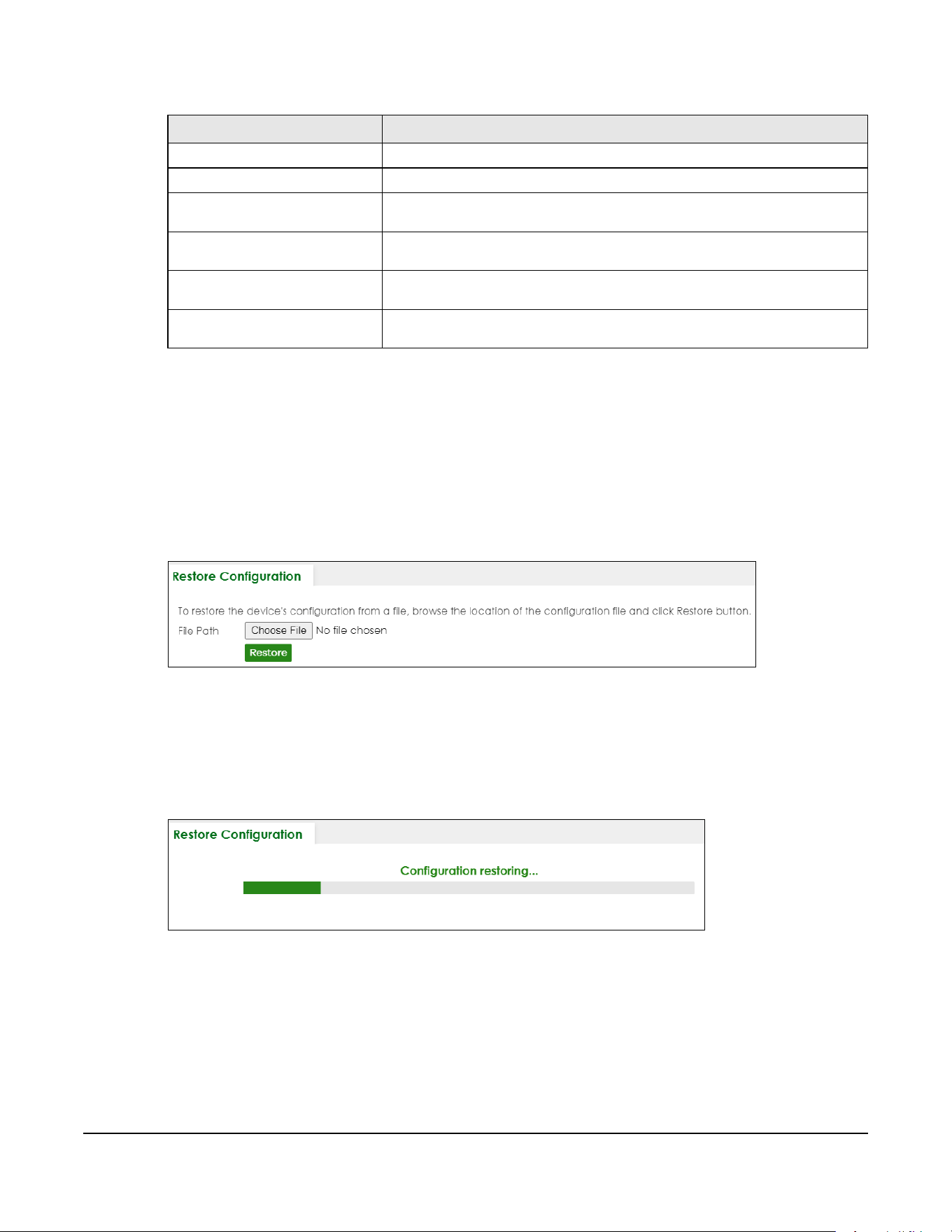
XGS2220 Series User’s Guide
613
The following table explains some of the FTP parameters.
79.8 Restore Configuration
Use this screen to restore a previously saved configuration file (See Section 79.9 on page 613 for more
information on how to back up a configuration file) from your computer to the Switch.
Click MAINTENANCE > Configuration > Restore Configuration to access this screen.
Figure 489 MAINTENANCE > Configuration > Restore Configuration
1 Click Choose File or Browse to locate the configuration file you wish to restore.
2 After you have specified the file, click Restore.
The Switch will run on the restored configuration after the restore process.
Figure 490 Configuration Restoring
79.9 Backup Configuration
Backing up your Switch configurations allows you to create various “snap shots” of your device from
which you may restore at a later date. Use this screen to back up your current Switch configuration to a
computer.
Table 322 FTP Upload to Cluster Member Example
FTP PARAMETER DESCRIPTION
User
Enter “admin”.
Password
The Web Configurator password default is 1234.
ls
Enter this command to list the name of cluster member switch’s firmware and
configuration file.
470ACAQ0.bin
This is the name of the firmware file you want to upload to the cluster member
switch.
fw-00-a0-c5-01-23-46
This is the cluster member switch’s firmware name as seen in the cluster
manager switch.
config-00-a0-c5-01-23-46
This is the cluster member switch’s configuration file name as seen in the cluster
manager switch.
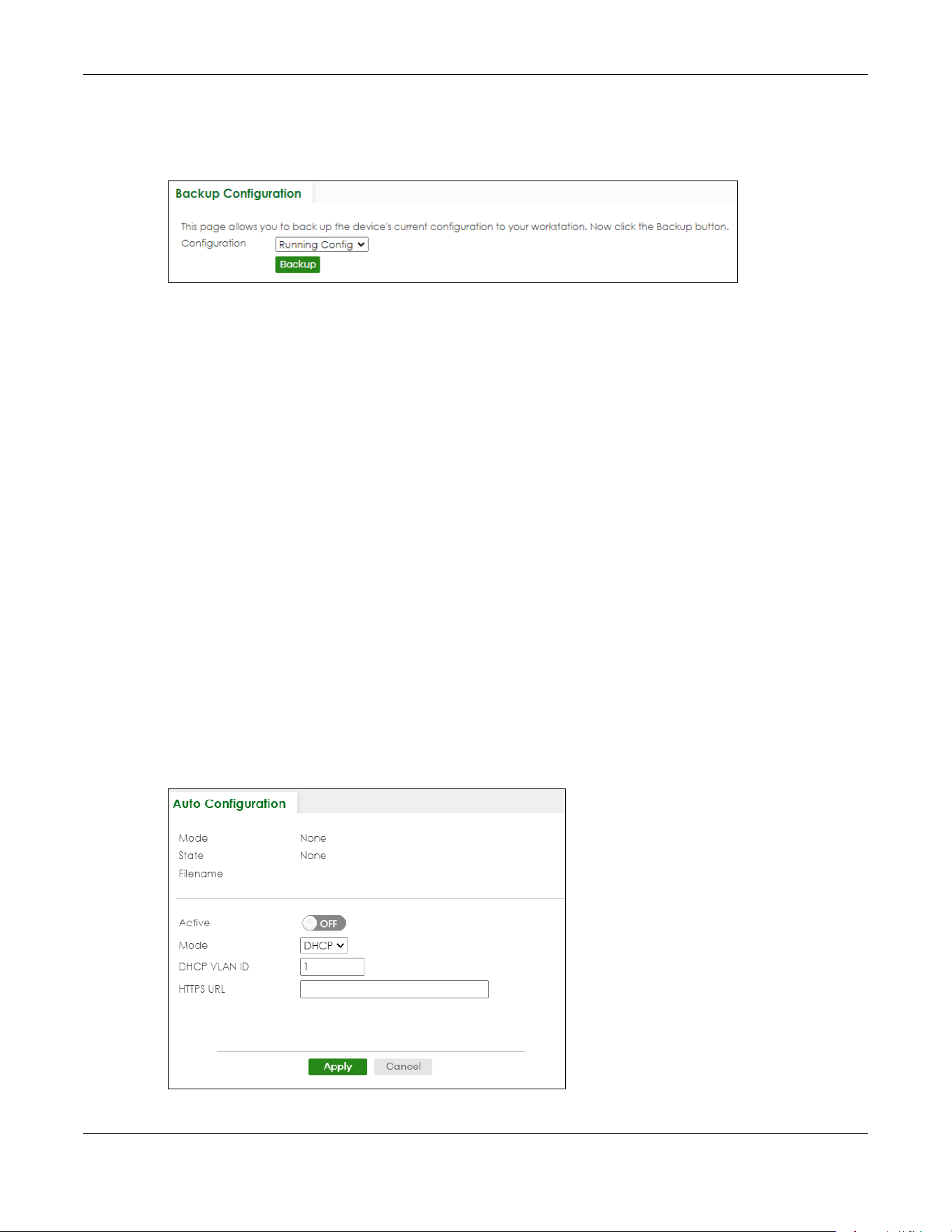
Chapter 79 MAINTENANCE
XGS2220 Series User’s Guide
614
To access this screen, click MAINTENANCE > Configuration > Backup Configuration in the navigation
panel.
Figure 491 MAINTENANCE > Configuration > Backup Configuration
Follow the steps below to back up the current Switch configuration to your computer in this screen.
1 Select which Switch configuration file you want to download to your computer.
2 Click Backup.
3 If the current configuration file is open and/or downloaded to your computer automatically, you can
click File > Save As on your computer to save the file to a specific place.
If a dialog box pops up asking whether you want to open or save the file, click Save or Save File to
download it to the default downloads folder on your computer. If a Save As screen displays after you
click Save or Save File, choose a location to save the file on your computer from the Save in drop-down
list box and type a descriptive name for it in the File name list box. Click Save to save the configuration
file to your computer.
79.10 Auto Configuration
The Switch can download a pre-saved auto configuration file automatically when you reboot the
Switch using the DHCP or HTTPS mode. This will overwrite the running configuration stored in the Switch’s
RAM instead of the startup configuration stored in the Switch’s flash memory.
To access this screen, click MAINTENANCE > Configuration > Auto Configuration in the navigation panel.
Figure 492 MAINTENANCE > Configuration > Auto Configuration

Chapter 79 MAINTENANCE
XGS2220 Series User’s Guide
615
The following table describes the labels in this screen.
79.11 Erase Running-Configuration
Follow the steps below to clear current configuration on the Switch. Note that this will NOT reset the
Switch back to its factory defaults. For example, if your Switch is set to Stacking mode and you click
erase running-configuration, after the Switch restarts, it will remain in Stacking mode. If you want to
change the Switch to its factory default Standalone mode, click the Factory Default button in
MAINTENANCE > Reboot System.
Table 323 MAINTENANCE > Configuration > Auto Configuration
LABEL DESCRIPTION
Use this section to view the auto configuration status after you restarted the Switch.
Mode This field shows the mode (DHCP or HTTPS) that is used for auto configuration after you enabled
auto configuration and restarted the Switch.
It shows None if auto configuration was not enabled.
State This field shows whether auto configuration was executed successfully the last time the Switch
rebooted.
None – Auto configuration was disabled and not executed.
Success – An auto configuration file was downloaded successfully to the Switch.
Un-success – An auto configuration file was not downloaded to the Switch.
Filename This field displays the name of the auto configuration file that was downloaded the last time the
Switch rebooted.
It shows blank if auto configuration was not enabled or not executed successfully.
Use this section to enable auto configuration and select the mode that you want to use for auto configuration.
Active Enable the switch button to enable auto configuration.
Mode Select DHCP to have the Switch use the TFTP server IP address and auto configuration file name
assigned by a DHCP server to download a pre-saved configuration file when the Switch
reboots.
Note: The Switch should act as a DHCP client to send a DHCP request with DHCP
option 60 so that it can get the TFTP server address and configuration file name
from the DHCP server.
Select HTTPS to have the Switch use the URL you specified in the HTTPS URL field to access a web
server and download the auto configuration file using HTTPS.
DHCP VLAN ID Enter the VLAN ID of the DHCP server that assigns the TFTP server IP address and auto
configuration file name to the Switch.
HTTPS URL Enter the URL that can be used to access and download the auto configuration file from a web
server using HTTPS. For example, https://webserverIPaddress/configfilename.cfg.
Note: You must fill in this field if you select HTTPS in the Mode field. Otherwise, auto
configuration will not work.
Apply Click Apply to save your changes to the Switch’s run-time memory. The Switch loses these
changes if it is turned off or loses power, so use the Save link on the top navigation panel to
save your changes to the non-volatile memory when you are done configuring.
Cancel Click Cancel to begin configuring this screen afresh.

Chapter 79 MAINTENANCE
XGS2220 Series User’s Guide
616
To access this screen, click MAINTENANCE > Configuration > Erase Running Configuration in the
navigation panel.
1 In the Erase Running Configuration screen, click the Erase button to clear all Switch configuration
information you configured and return to the Zyxel default configuration settings.
Figure 493 MAINTENANCE > Configuration > Erase Running Configuration
2 Click YES to remove the running configuration on the Switch.
Figure 494 Erase Running Configuration: Confirmation
3 In the Web Configurator, click the Save button in the top of the screen to make the changes take
effect. If you want to access the Switch Web Configurator again, you may need to change the IP
address of your computer to be in the same subnet as that of the default Switch IP address (192.168.1.1
or DHCP-assigned IP).
79.12 Save Configuration
To access this screen, click MAINTENANCE > Configuration > Save Configuration in the navigation panel.
Click Config 1 to save the current configuration settings permanently to Configuration 1 on the Switch.
These configurations are set up according to your network environment.
Click Config 2 to save the current configuration settings permanently to Configuration 2 on the Switch.
These configurations are set up according to your network environment.
Click Custom Default to save the current configuration settings permanently to a customized default file
on the Switch. If configuration changes cause the Switch to behave abnormally, click Custom Default
(in the MAINTENANCE > Reboot System screen) to have the Switch automatically reboot and restore the
saved Custom Default configuration file.
Figure 495 MAINTENANCE > Configuration > Save Configuration
Note: If a customized default file was not saved, clicking Custom Default in the MAINTENANCE
> Reboot System screen loads the factory default configuration on the Switch.
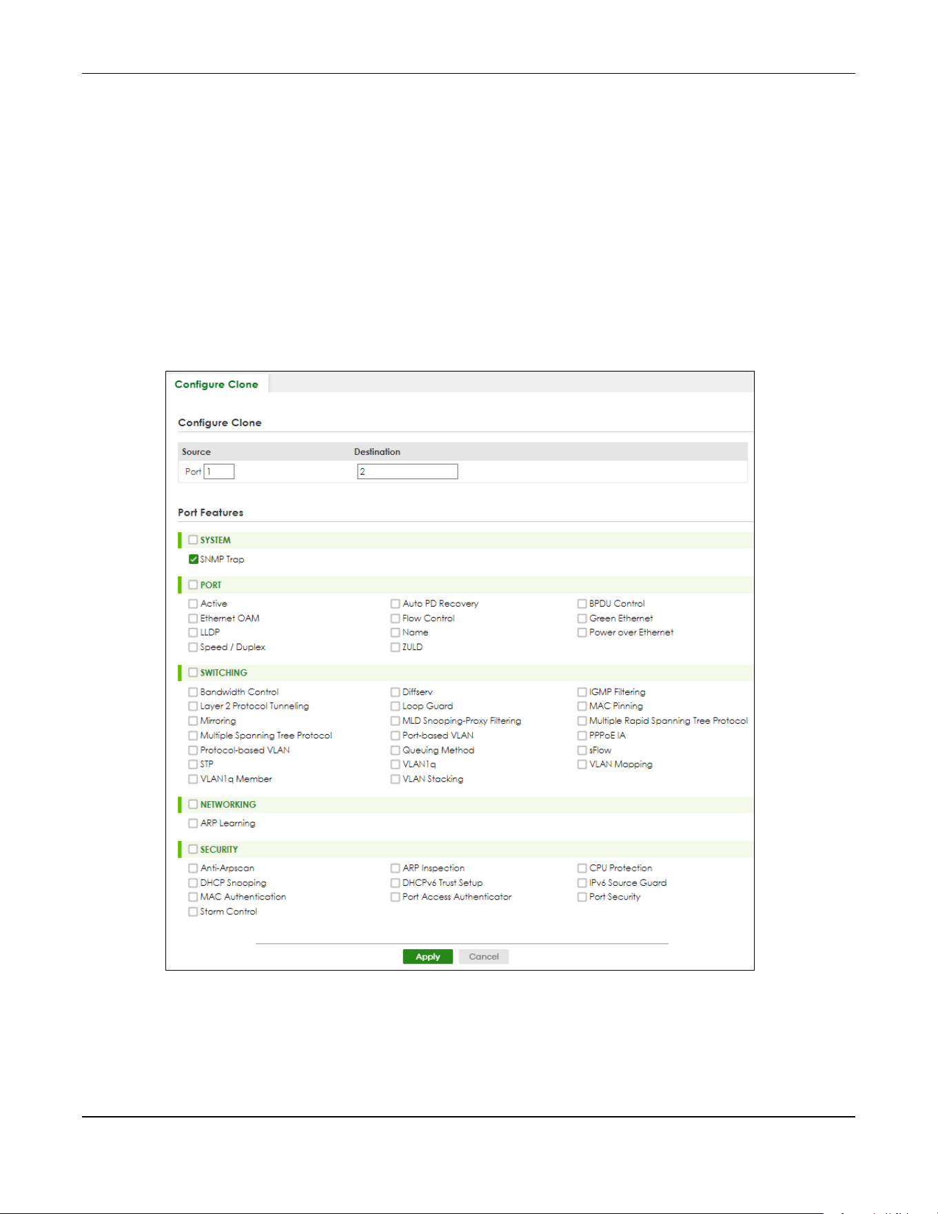
Chapter 79 MAINTENANCE
XGS2220 Series User’s Guide
617
Alternatively, click Save on the top right in any screen to save the configuration changes to the current
configuration.
Note: Clicking the Apply button after making configuration does NOT save the changes
permanently. All unsaved changes are erased after you reboot the Switch.
79.13 Configure Clone
Cloning allows you to copy the basic and advanced settings from a source port to a destination port or
ports. Click MAINTENANCE > Configuration > Configure Clone to open the following screen.
Figure 496 MAINTENANCE > Configuration > Configure Clone (Standalone Mode)

Chapter 79 MAINTENANCE
XGS2220 Series User’s Guide
618
Figure 497 MAINTENANCE > Configuration > Configure Clone (Stacking Mode)
The following table describes the labels in this screen.
Table 324 MAINTENANCE > Configuration > Configure Clone
LABEL DESCRIPTION
Configure Clone
Source/
Destination
In Stacking mode, a port is defined by a slot ID representing the Switch in the stack and a port
number.
Select the source port and slot (in Stacking mode) under the Source label. This port’s attributes are
copied.
Enter the destination port or ports under the Destination label. These are the ports which are going
to have the same attributes as the source port. You can enter individual ports separated by a
comma or a range of ports by using a hyphen. For example, 2, 4, 6 indicates that ports 2, 4 and 6
are the destination ports. 2-6 indicates that ports 2 through 6 are the destination ports.
In Stacking mode, you can select multiple destination slots.
Port Features
Select a feature’s check box to select a specific feature. Otherwise, select the check box in the
table heading row to select all features for a category.
SYSTEM Select the system feature (you configured in the SYSTEM menus) to be copied to the destination
ports. Otherwise, select the SYSTEM check box in the table heading row to select all features for a
category.
PORT Select which port features (you configured in the PORT menus) should be copied to the
destination ports. Otherwise, select the PORT check box in the table heading row to select all
features for a category.

Chapter 79 MAINTENANCE
XGS2220 Series User’s Guide
619
79.14 Diagnostic
Click MAINTENANCE > Diagnostic in the navigation panel to open this screen. Use this screen to ping IP
addresses, run a traceroute, perform port tests or show the Switch’s location between devices.
SWITCHING Select which switching features (you configured in the SWITCHING menus) should be copied to
the destination ports. Otherwise, select the SWITCHING check box in the table heading row to
select all features for a category.
NETWORKING Select the networking feature (you configured in the NETWORKING menus) to be copied to the
destination ports. Otherwise, select the NETWORKING check box in the table heading row to
select all features for a category.
SECURITY Select which security features (you configured in the SECURITY menus) should be copied to the
destination ports. Otherwise, select the SECURITY check box in the table heading row to select all
features for a category.
Apply Click Apply to save your changes to the Switch’s run-time memory. The Switch loses these
changes if it is turned off or loses power, so use the Save link on the top navigation panel to save
your changes to the non-volatile memory when you are done configuring.
Cancel Click Cancel to begin configuring this screen afresh.
Table 324 MAINTENANCE > Configuration > Configure Clone (continued)
LABEL DESCRIPTION

Chapter 79 MAINTENANCE
XGS2220 Series User’s Guide
620
Figure 498 MAINTENANCE > Diagnostic (Standalone Mode)

Chapter 79 MAINTENANCE
XGS2220 Series User’s Guide
621
Figure 499 MAINTENANCE > Diagnostic (Stacking Mode)
The following table describes the labels in this screen.
Table 325 MAINTENANCE > Diagnostic
LABEL DESCRIPTION
Ping Test
IPv4 Select this option if you want to ping an IPv4 address. Otherwise, select – to send ping
requests to all VLANs on the Switch.
IPv6 Select this option if you want to ping an IPv6 address. You can also select vlan and specify
the ID number of the VLAN to which the Switch is to send ping requests. Otherwise, select – to
send ping requests to all VLANs on the Switch.
IP Address/Host
Name
Type the IP address or host name of a device that you want to ping in order to test a
connection.
Click Ping to have the Switch ping the IP address.
Source IP
Address
Type the source IP address that you want to ping in order to test a connection.
Click Ping to have the Switch ping the IP address.
Count Enter the number of ICMP Echo Request (ping) messages the Switch continuously sends.
Trace Route Test
IPv4 Select this option if you want to trace the route packets taken to a device with an IPv4
address. Otherwise, select – to trace the path on any VLAN.
Note: The device to which you want to run a traceroute must belong to the VLAN
you specify here.
IPv6 Select this option if you want to trace the route packets taken to a device with an IPv6
address.

Chapter 79 MAINTENANCE
XGS2220 Series User’s Guide
622
79.15 Firmware Upgrade
You can upgrade the Switch’s firmware through Web Configurator or NCC.
Firmware Upgrade Through NCC
In cloud management mode, NCC will first check if the firmware on the Switch needs to be upgraded. If
it does, the Switch will upgrade the firmware immediately. If the firmware does not need to be
upgraded, but there is newer firmware available for the Switch, then it will be upgraded according to
the firmware upgrade schedule for the Switch on the NCC.
On the NCC web portal, go to Site-wide > Configure > Firmware management to schedule the firmware
upgrade time.
Note: While the Switch is rebooting, do NOT turn off the power.
IP Address/Host
Name
Enter the IP address or host name of a device to which you want to perform a traceroute.
Click Trace Route to have the Switch perform the traceroute function. This determines the
path a packet takes to the specified device.
TTL Enter the Time To Live (TTL) value for the ICMP Echo Request packets. This is to set the
maximum number of the hops (routers) a packet can travel through. Each router along the
path will decrement the TTL value by one and forward the packets. When the TTL value
becomes zero and the destination is not found, the router drops the packets and informs the
sender.
Wait Time Specify how many seconds the Switch waits for a response to a probe before running
another traceroute.
Queries Specify how many times the Switch performs the traceroute function.
Ethernet Port Test
Port The slot field appears only in Stacking mode. Click the drop-down list to choose the slot
number of the Switch in a stack. Enter a port number and click Port Test to perform an
internal loopback test.
Cable Diagnostics
Port The slot field appears only in Stacking mode. Click the drop-down list to choose the slot
number of the Switch in a stack. Enter an Ethernet port number and click Diagnose to
perform a physical wire-pair test of the Ethernet connections on the specified ports. The
following fields display when you diagnose a port.
This field is available only on the Switch that has one or more copper Ethernet ports (except
the MGMT port).
Port Enter an Ethernet port number and click Diagnose to perform a physical wire-pair test of the
Ethernet connections on the specified ports. The following fields display when you diagnose
a port.
Locator LED Enter a time interval (in minutes) and click Blink to show the actual location of the Switch
between several devices in a rack.
The default time interval is 30 minutes.
Click Stop to have the Switch terminate the blinking locater LED.
Table 325 MAINTENANCE > Diagnostic (continued)
LABEL DESCRIPTION
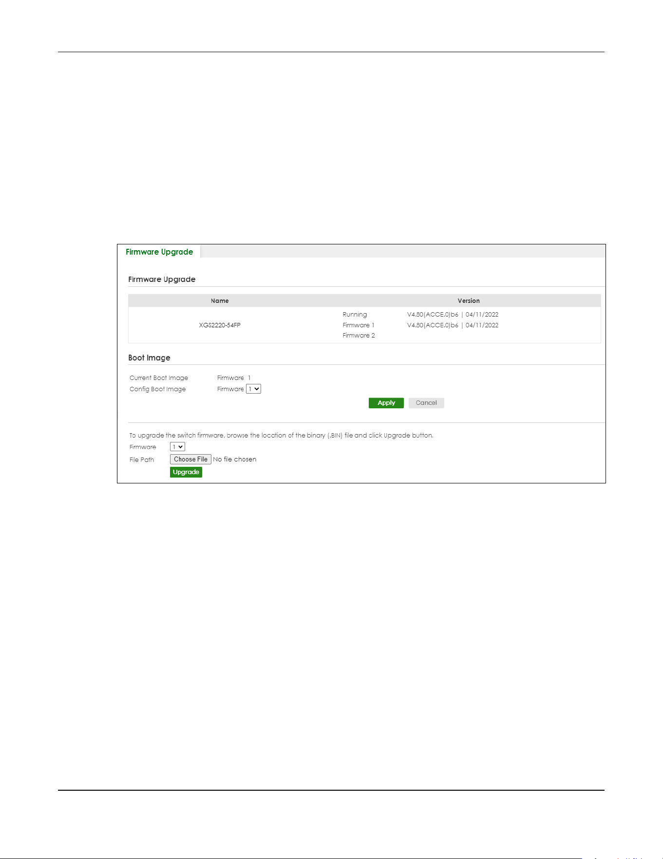
Chapter 79 MAINTENANCE
XGS2220 Series User’s Guide
623
Firmware Upgrade Through the Web Configurator
Use the following screen to upgrade your Switch to the latest firmware. The Switch supports dual
firmware images, Firmware 1 and Firmware 2. Use this screen to specify which image is updated when
firmware is uploaded using the Web Configurator and to specify which image is loaded when the
Switch starts up.
Note: Make sure you have downloaded (and unzipped) the correct model firmware and
version to your computer before uploading to the device.
Click MAINTENANCE > Firmware Upgrade to view the screen as shown next.
Figure 500 MAINTENANCE > Firmware Upgrade (Standalone Mode)

Chapter 79 MAINTENANCE
XGS2220 Series User’s Guide
624
Figure 501 MAINTENANCE > Firmware Upgrade (Stacking Mode)
The top of the screen shows which firmware version is currently Running on the Switch. Click Choose File
or Browse to locate the firmware file you wish to upload to the Switch in the File Path field. Click Upgrade
to load the new firmware. The Switch does not apply the uploaded firmware immediately. Firmware
upgrades are only applied after you reboot the Switch using the uploaded firmware.
Click the Config Boot Image drop-down list box to select the boot image (Firmware1 or Firmware2) you
want the Switch to use when rebooting, click Apply. Restart the Switch (manually or using the
MAINTENANCE > Reboot System screen) to apply the firmware image you selected.
After the process is complete, see the DASHBOARD screen to verify your current firmware version
number.
Table 326 MAINTENANCE > Firmware Upgrade
LABEL DESCRIPTION
Slot This field appears only in Stacking mode.
This is the slot index number.
Name This is the name of the Switch that you are configuring.

Chapter 79 MAINTENANCE
XGS2220 Series User’s Guide
625
79.16 Reboot System
Reboot System allows you to restart the Switch without physically turning the power off. It also allows you
to load configuration one (Config 1), configuration two (Config 2), a Custom Default or the Factory
Default configuration when you reboot. Follow the steps below to reboot the Switch.
Click MAINTENANCE > Reboot System to view the screen as shown next.
Status This field displays whether the stacked Switch is active or inactive in a stack system.
Init means the master Switch is initializing the slot ID.
active* means the Switch is in the stack, but some items fail to initialize. See the system logs
for details.
• If the Switch is not the master, disconnect and reconnect the stacking port and wait.
Restart the Switch if it still displays active*.
• If the Switch is a master, restart the Switch or select another master.
Version The Switch has 2 firmware sets, Firmware 1 and Firmware 2, residing in flash.
• Running shows the version number (and model code) and MM/DD/YYYY creation date
of the firmware currently in use on the Switch (Firmware 1 or Firmware 2). The firmware
information is also displayed at System Information in Basic Setting.
• Firmware 1 shows its version number (and model code) and MM/DD/YYYY creation
date.
• Firmware 2 shows its version number (and model code) and MM/DD/YYYY creation
date.
Boot Image
Current Boot Image This displays which firmware is currently in use on the Switch (Firmware 1 or Firmware 2).
Config Boot Image Select which firmware (Firmware 1 or Firmware 2) should load, click Apply and reboot the
Switch to see changes, you will also see changes in the Current Boot Image field above as
well.
Apply Click Apply to save your changes to the Switch’s run-time memory. The Switch loses these
changes if it is turned off or loses power, so use the Save link on the top navigation panel to
save your changes to the non-volatile memory when you are done configuring.
Cancel Click Cancel to begin configuring this screen afresh.
Firmware Choose to upload the new firmware to (Firmware) 1 or (Firmware) 2.
In Stacking mode, the first field is the slot number. Click the drop-down list to choose the
slot number of the Switch in a stack to upgrade the firmware on this slot. Or select All to
upgrade the firmware for all slots.
File Path Click Choose File or Browse to locate the firmware file you wish to upload to the Switch.
Upgrade Click Upgrade to load the new firmware. Firmwares are only applied after a reboot. To
reboot, go to MAINTENANCE > Reboot System and click Config 1
, Config 2 or Factory
Default (Config 1, Config 2, Factory Default, and Custom Default are the configuration files
you want the Switch to use when it restarts). In Stacking mode, you can also choose
Stacking Default to reboot.
Table 326 MAINTENANCE > Firmware Upgrade (continued)
LABEL DESCRIPTION
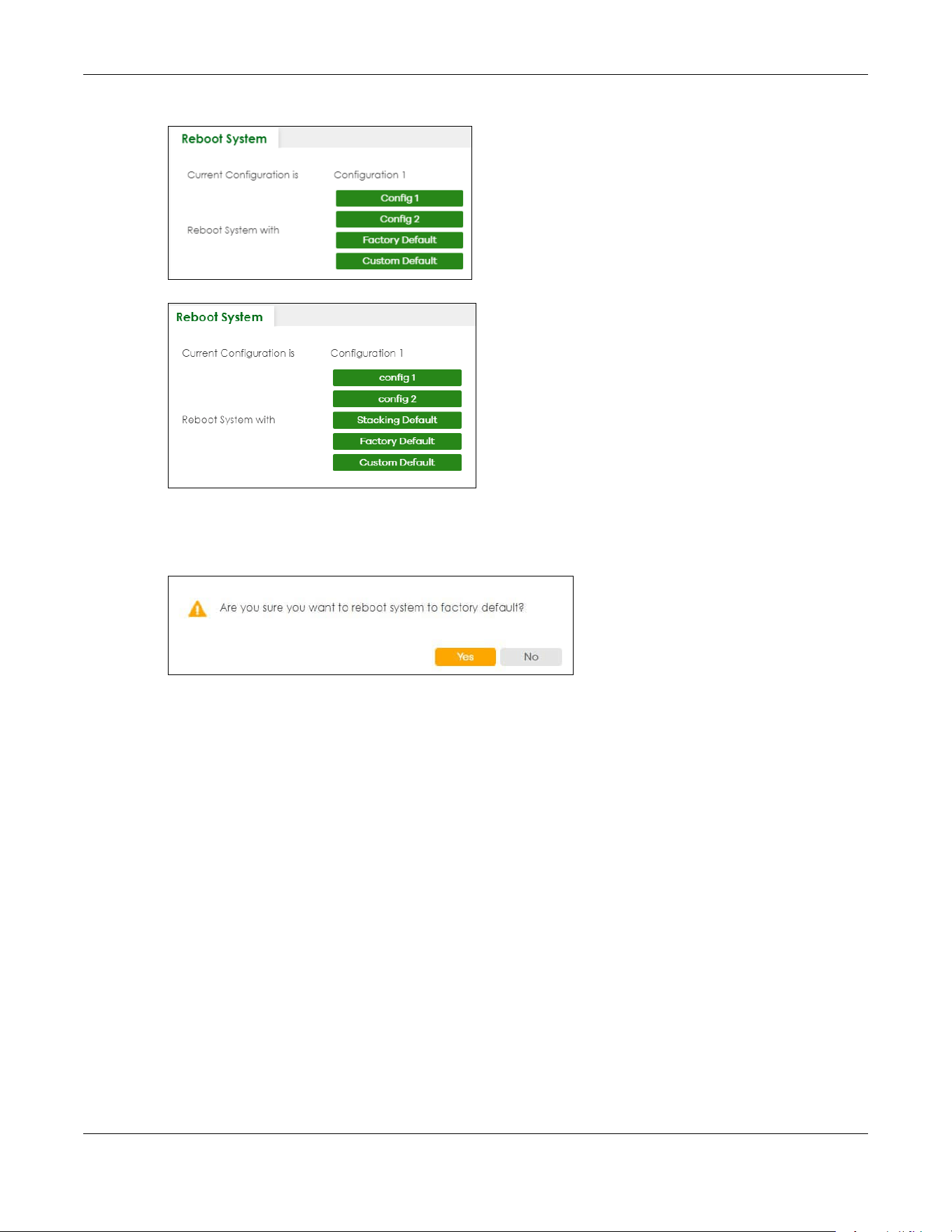
Chapter 79 MAINTENANCE
XGS2220 Series User’s Guide
626
Figure 502 MAINTENANCE > Reboot System (Standalone Mode)
Figure 503 MAINTENANCE > Reboot System (Stacking Mode)
1 Click the Config 1, Config 2, Factory Default, or Custom Default (or Stacking Default in Stacking mode)
button to reboot and load that configuration file. The confirmation screen displays.
Figure 504 Reboot Confirmation
2 Click YES and then wait for the Switch to restart. This takes up to 2 minutes.
Click Config 1 and follow steps 1 to 2 to reboot and load configuration one on the Switch.
Click Config 2 and follow steps 1 to 2 to reboot and load configuration two on the Switch.
Click Stacking Default and follow steps 1 to 2 to reboot and load stacking default configuration settings
on the Switch. The master Switch login information will not be reset.
Click Factory Default and follow steps 1 to 2 to reboot and load Zyxel factory default configuration
settings on the Switch.
Click Custom Default and follow steps 1 to 2 to reboot and load a customized default file on the Switch.
This will save the custom default configuration settings to both Configuration 1 and Configuration 2.
Note: If a customized default file was not saved, clicking Custom Default loads the factory
default configuration on the Switch.
Note: Service Register only appears in standalone mode.

Chapter 79 MAINTENANCE
XGS2220 Series User’s Guide
627
79.17 Tech-Support
The Tech-Support feature is a log enhancement tool that logs useful information such as CPU utilization
history, memory and Mbuf (Memory Buffer) log and crash reports for issue analysis by customer support
should you have difficulty with your Switch. The Tech Support menu eases your effort in obtaining reports
and it is also available in CLI command by entering the “Show tech-support” command.
Click MAINTENANCE > Tech-Support to see the following screen.
Figure 505 MAINTENANCE > Tech-Support
You may need WordPad or similar software to see the log report correctly. The table below describes
the fields in the above screen.
Table 327 MAINTENANCE > Tech-Support
LABEL DESCRIPTION
CPU Type a number ranging from 50 to 100 in the CPU threshold box, and type another
number ranging from 5 to 60 in the seconds box then click Apply.
For example, 80 for CPU threshold and 5 for seconds means a log will be created when
CPU utilization reaches over 80% and lasts for 5 seconds.
The log report holds 7 days of CPU log data and is stored in volatile memory (RAM). The
data is lost if the Switch is turned off or in event of power outage. After 7 days, the logs
wrap around and new ones and replace the earliest ones.
The higher the CPU threshold number, the fewer logs will be created, and the less data
technical support will have to analyze and vice versa.
Mbuf Type a number ranging from 50 to 100 in the Mbuf (Memory Buffer) threshold box. The
Mbuf log report is stored in flash (permanent) memory.
For example, Mbuf 50 means a log will be created when the Mbuf utilization is over 50%.
The higher the Mbuf threshold number, the fewer logs will be created, and the less data
technical support will have to analyze and vice versa.
Apply Click Apply to save your changes to the Switch’s run-time memory. The Switch loses
these changes if it is turned off or loses power, so use the Save link on the top navigation
panel to save your changes to the non-volatile memory when you are done configuring.
Cancel Click Cancel to begin configuring this screen afresh.

Chapter 79 MAINTENANCE
XGS2220 Series User’s Guide
628
79.17.1 Tech-Support Download
When you click Download to save your current Switch configuration to a computer, the following screen
appears. When the log report has downloaded successfully, click Back to return to the previous screen.
Figure 506 MAINTENANCE > Tech-Support: Download
All Click Download to see all the log report and system status. This log report is stored in flash
memory. If the All log report is too large, you can download the log reports separately
below.
Crash Click Download to see the crash log report. The log will include information of the last
crash and is stored in flash memory.
CPU Click Download to see the CPU history log report. The 7-days log is stored in RAM and you
will need to save it, otherwise it will be lost when the Switch is shutdown or during power
outage.
Memory Click Download to see the memory section log report. This log report is stored in flash
memory.
Mbuf Click Download to see the Mbuf (Memory Buffer) log report. This log report is stored in
flash memory.
ROM Click Download to see the Read Only Memory (ROM) log report. This report is stored in
flash memory.
L3 Click Download to see the layer-3 Switch log report. The log only applies to the layer-3
Switch models. This report is stored in flash memory.
Table 327 MAINTENANCE > Tech-Support (continued)
LABEL DESCRIPTION
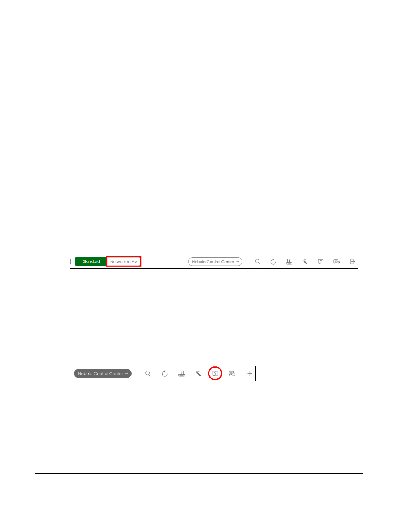
XGS2220 Series User’s Guide
629
CHAPTER 80
Networked AV Mode
80.1 Overview
Aside from the Web Configurator in Standard mode that has a complete set of configuration for
network installation, you can switch to Networked AV mode. Networked AV mode contains just the
necessary configurations for setting up and managing audio-video traffic on your network.
AV over IP is the transmission of audio-video data over an IP network.
Use a browser that supports HTML5, such Microsoft Edge, Mozilla Firefox, or Google Chrome. The
recommended minimum screen resolution is 1024 by 768 pixels.
The following sections introduces the configuration and functions of the Web Configurator In Networked
AV mode.
Click Networked AV at the top left of the Web Configurator to switch between the Web Configurator’s
Standard or Networked AV mode.
Figure 507 Web Configurator – Networked AV Mode Switch
80.2 Help
The Web Configurator’s online help has descriptions of individual Networked AV mode screens and
some supplementary information.
Click the Help link from a Web Configurator screen to scan the QR code or click the web link to display
the online help.
Figure 508 Open the Online Help
80.3 Summary
Use the SUMMARY screen to see the Switch’s front panel port status, connected ports information,
networked AV information, Nebula Cloud Control status, and a link to go to the IP Setup screen (Section
80.11 on page 637).
The SUMMARY screen displays when you log into the Switch in Networked AV mode.

Chapter 80 Networked AV Mode
XGS2220 Series User’s Guide
630
Figure 509 Summary (example PoE model)
The following table describes the labels in this screen.
Table 328 SUMMARY
LABEL DESCRIPTION
Auto Refresh Click the Pause Auto Refresh or Resume Auto Refresh icon to stop or resume the screen update.
Port Status This chart displays the status of the Switch’s front panel ports with connection (LED and Port).
Networked AV Information
IP Setup This link takes you to a screen where you can configure the IP address and subnet mask
(necessary for Switch management) and set up to 128 IP routing domains.
IGMP-Snooping
VLAN
This displays the ID number of the VLAN group upon which the Switch is to perform IGMP
snooping.
IGMP-Snooping This displays Active when IGMP snooping is enabled to forward group multicast traffic only to
ports that are members of that group.
Otherwise, it is Inactive.
IGMP-Querier This displays Active when the Switch is allowed to send IGMP General Query messages to the
VLANs with the multicast hosts attached.
Otherwise, it is Inactive.
IP Interface This displays the IP address of the Switch for it to be managed over the network.
Unknown
Multicast
This displays the action to perform when the Switch receives an unknown multicast frame.
It displays Drop when the frames are discarded.
It displays Flooding when the frames are sent to all ports.
It displays Drop on VLAN when the frames are discarded on the specified VLANs.
Power Usage(W) For PoE models.
This chart displays the used PoE Watts over the total number of Watts provided on this Switch.
Chapter 80 Networked AV Mode
XGS2220 Series User’s Guide
631
80.4 MONITOR
The following sections introduce the MONITOR screens.
80.5 What You Can Do
• Use the System Information screen (Section 80.6 on page 631) to check the firmware version number
and monitor the Switch temperature.
80.6 System Information
In the navigation panel, click MONITOR > System Information to display the screen as shown. Use this
screen to view general system information. You can check the firmware version number and monitor
the Switch temperature.
Cloud Control
Status
This displays the registration and connection status between the Switch and the NCC (Nebula
Control Center).
Click NCC Discovery or the switch button to go to SYSTEM > Cloud Management screen.
Port This displays the port of this Switch.
Port Name This displays the port description of this Switch.
Link Speed This displays the speed (either 100M for 100 Mbps, 1G for 1 Gbps, 2.5G for 2.5 Gbps, 5G for 5
Gbps, or 10G for 10 Gbps) and the duplex (F for full duplex or H for half). It also shows the cable
type (Copper or Fiber) for the combo ports. This field displays Down if the port is not connected
to any device.
Bandwidth
Usage (Tx)
Bandwidth
Usage (Rx)
These display the percentage of bandwidth usage on this port as a percentage of the Link
Speed.
IGMP Leave
Mode
This displays Immediate when the Switch receives IGMP leave packets, the Switch will close the
multicast stream immediately without any further action.
This displays Fast when the Switch will further generate a group specific query packet to all the
receivers. This could prevent the traffic being cut if some receivers still want to receive the
multicast stream.
This displays Normal when the Switch receives an IGMP leave message from a host on a port, it
forwards the message to the multicast router. The multicast router then sends out an IGMP
Group-Specific Query (GSQ) message to determine whether other hosts connected to the port
should remain in the specific multicast group. The Switch forwards the query message to all hosts
connected to the port and waits for IGMP reports from hosts to update the forwarding table for
this port.
Table 328 SUMMARY (continued)
LABEL DESCRIPTION

Chapter 80 Networked AV Mode
XGS2220 Series User’s Guide
632
Figure 510 MONITOR > System Information
The following table describes the labels in this screen.
Table 329 MONITOR > System Information
LABEL DESCRIPTION
System Information
System Name This field displays the descriptive name of the Switch for identification purposes.
Product Model This field displays the product model of the Switch. Use this information when searching for
firmware upgrade or looking for other support information in the website.
ZyNOS F/W
Version
This field displays the version number of the Switch 's current firmware including the creation date.
Ethernet
Address
This field refers to the Ethernet MAC (Media Access Control) address of the Switch.
CPU Utilization
Current (%)
CPU utilization quantifies how busy the system is. Current (%) displays the current percentage of
CPU utilization.
Memory Utilization
Memory utilization shows how much DRAM memory is available and in use. It also displays the current percentage
of memory utilization.
Name This field displays the name of memory pool.
Total (byte) This field displays the total number of bytes in this memory pool.
Used (byte) This field displays the number of bytes being used in this memory pool.
Utilization
(%)
This field displays the percentage (%) of memory being used in this memory pool.
Hardware Monitor

Chapter 80 Networked AV Mode
XGS2220 Series User’s Guide
633
80.7 SYSTEM
The following sections introduces the SYSTEM screens.
80.8 What You Can Do
• Use the Cloud Management screen (Section 80.9 on page 634) to view NCC Connection status and
enable/disable NCC Discovery.
• Use the General Setup screen (Section 80.10 on page 635) to configure general settings such as the
system name and time.
• Use the IP Setup screen (Section 80.11 on page 637) to configure the default gateway device, the
default domain name server and add IP domains.
• Use the Logins screen (Section 80.12 on page 639) to change the system password, configure
passwords for up to four users and set their privilege level.
Temperature
(C/F)
BOARD/MAC/PHY refers to the location of the temperature sensor on the Switch printed circuit
board.
Status This field displays Normal for temperatures below the threshold and Error for those above.
Current This shows the current temperature at this sensor.
MAX This field displays the maximum temperature measured at this sensor.
MIN This field displays the minimum temperature measured at this sensor.
Threshold This field displays the upper temperature limit at this sensor.
Fan Speed
(RPM)
A properly functioning fan is an essential component (along with a sufficiently ventilated, cool
operating environment) in order for the device to stay within the temperature threshold. Each
fan has a sensor that is capable of detecting and reporting if the fan speed falls below the
threshold shown.
Status Normal indicates that this fan is functioning above the minimum speed. Error indicates that this
fan is functioning below the minimum speed.
Current This field displays this fan's current speed in Revolutions Per Minute (RPM).
MAX This field displays this fan's maximum speed measured in Revolutions Per Minute (RPM).
MIN This field displays this fan's minimum speed measured in Revolutions Per Minute (RPM). "<41" is
displayed for speeds too small to measure (under 2000 RPM).
Threshold This field displays the minimum speed at which a normal fan should work.
Voltage(V) The power supply for each voltage has a sensor that is capable of detecting and reporting if the
voltage falls out of the tolerance range.
Status Normal indicates that the voltage is within an acceptable operating range at this point;
otherwise Error is displayed.
Current This is the current voltage reading.
MAX This field displays the maximum voltage measured at this point.
MIN This field displays the minimum voltage measured at this point.
Threshold This field displays the percentage tolerance of the voltage with which the Switch still works.
Table 329 MONITOR > System Information (continued)
LABEL DESCRIPTION

Chapter 80 Networked AV Mode
XGS2220 Series User’s Guide
634
• Use the SNMP screen (Section 80.13 on page 641) to configure your SNMP (Simple Network
Management Protocol) settings.
• Use the SNMP User screen (Section 80.14 on page 643) to create SNMP users for authentication with
managers using SNMP v3 and associate them to SNMP groups.
• Use the SNMP Trap Group screen (Section 80.15 on page 645) to specify the types of SNMP traps that
should be sent to each SNMP manager.
• Use the SNMP Trap Port screen (Section 80.16 on page 646) to set whether a trap received on the
ports would be sent to the SNMP manager.
80.9 Cloud Management
The Zyxel Nebula Control Center (NCC) is a cloud-based network management system that allows you
to remotely manage and monitor Zyxel Nebula APs, Ethernet switches and security gateways.
The Switch is managed and provisioned automatically by the NCC (Nebula Control Center) when:
• It is connected to the Internet.
• The Nebula Control Center Discovery feature is enabled.
• It has been registered in the NCC.
Click SYSTEM > Cloud Management in the navigation panel to display this screen.
Figure 511 SYSTEM > Cloud Management

Chapter 80 Networked AV Mode
XGS2220 Series User’s Guide
635
The following table describes the labels in this screen.
Enable Nebula Control Center (NCC) Discovery to turn on NCC discovery on the Switch. If the Switch
has Internet access and has been registered in the NCC, it will go into cloud management mode.
Disable Nebula Control Center (NCC) Discovery to turn off NCC discovery on the Switch. The Switch will
NOT discover the NCC and remain in standalone mode.
This screen has a QR code containing the Switch’s serial number and Registration MAC address for
handy NCC registration of the Switch using the Nebula Mobile app. First, download the app from the
Google Play store for Android devices or the App Store for iOS devices and create an organization and
site. Open the Nebula Mobile app and follow the wizard to scan the Register Device QR code to register
the Switch on NCC.
80.10 General Setup
Use this screen to configure general settings such as the system name and time. Click SYSTEM > General
Setup in the navigation panel to display the screen as shown.
Table 330 SYSTEM > Cloud Management
LABEL DESCRIPTION
Nebula Control
Center (NCC)
Discovery
Enable the switch button to turn on Nebula Control Center (NCC) discovery on the Switch.
This field displays:
• The Switch Internet connection status.
• The connection status between the Switch and NCC.
• The Switch registration status on NCC.
Mouse over the circles to display detailed information.
To pass your Switch management to NCC, first make sure your Switch is connected to the
Internet. Then go to NCC and register your Switch.
1. Internet
Green – The Switch is connected to the Internet.
Orange – The Switch is not connected to the Internet.
2. Nebula
Green – The Switch is connected to NCC.
Orange – The Switch is not connected to NCC.
3. Registration
Green – The Switch is registered on NCC.
Gray – The Switch is not registered on NCC.
Note: All circles will gray out if you disable Nebula Discovery.
Connection
Status
This table displays the NCC connection status information.
Use the status logs in the Internet, Nebula, and Registration fields for connection
troubleshooting.
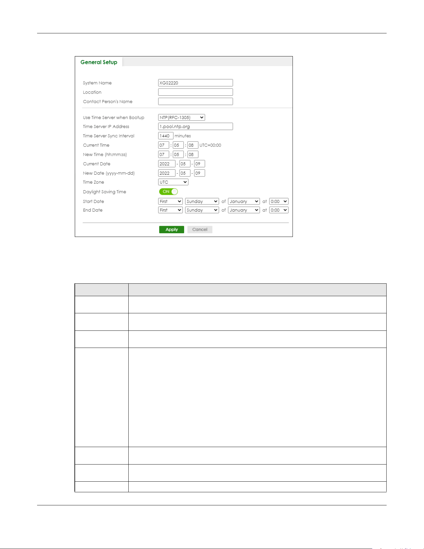
Chapter 80 Networked AV Mode
XGS2220 Series User’s Guide
636
Figure 512 SYSTEM > General Setup
Note: The input string of any field in this screen should not contain [ ? ], [ | ], [ ' ], [ " ], or [ , ].
The following table describes the labels in this screen.
Table 331 SYSTEM > General Setup
LABEL DESCRIPTION
System Name Choose a descriptive name for identification purposes. This name consists of up to 64 printable
ASCII characters; spaces are allowed.
Location Enter the geographic location of your Switch. You can use up to 128 printable ASCII
characters; spaces are allowed.
Contact Person's
Name
Enter the name of the person in charge of this Switch. You can use up to 32 printable ASCII
characters; spaces are allowed.
Use Time Server
when Bootup
Enter the time service protocol that your time server uses. Not all time servers support all
protocols, so you may have to use trial and error to find a protocol that works. The main
differences between them are the time format.
When you select the Daytime (RFC-867) format, the Switch displays the day, month, year and
time with no time zone adjustment. When you use this format it is recommended that you use a
Daytime timeserver within your geographical time zone.
Time (RFC-868) format displays a 4-byte integer giving the total number of seconds since 1970/
1/1 at 00:00:00.
NTP (RFC-1305) is similar to Time (RFC-868).
None is the default value. Enter the time manually. Each time you turn on the Switch, the time
and date will be reset to 2022-01-01 00:00:00.
Time Server IP
Address
Enter the IP address or domain name of your timeserver. The Switch searches for the timeserver
for up to 60 seconds.
Time Server Sync
Interval
Enter the period in minutes between each time server synchronization. The Switch checks the
time server after every synchronization interval.
Current Time This field displays the time you open this menu (or refresh the menu).

Chapter 80 Networked AV Mode
XGS2220 Series User’s Guide
637
80.11 IP Setup
Use the IP Setup screen to configure the default gateway device, the default domain name server and
add IP domains.
Note: The Switch allows you to set a static IP interface in the same subnet that already has a
DHCP-assigned IP interface on the Switch. The Switch will use the static IP you set and
the DHCP-assigned IP will be set to 0.0.0.0.
New Time
(hh:mm:ss)
Enter the new time in hour, minute and second format. The new time then appears in the
Current Time field after you click Apply.
Current Date This field displays the date you open this menu.
New Date (yyyy-
mm-dd)
Enter the new date in year, month and day format. The new date then appears in the Current
Date field after you click Apply.
Time Zone Select the time difference between UTC (Universal Time Coordinated, formerly known as GMT,
Greenwich Mean Time) and your time zone from the drop-down list box.
Daylight Saving
Time
Daylight saving is a period from late spring to early fall when many countries set their clocks
ahead of normal local time by one hour to give more daytime light in the evening.
Enable the switch button if you use Daylight Saving Time.
Start Date Configure the day and time when Daylight Saving Time starts if you selected Daylight Saving
Time. The time is displayed in the 24 hour format. Here are a couple of examples:
Daylight Saving Time starts in most parts of the United States on the second Sunday of March.
Each time zone in the United States starts using Daylight Saving Time at 2 A.M. local time. So in
the United States you would select Second, Sunday, March and 2:00.
Daylight Saving Time starts in the European Union on the last Sunday of March. All of the time
zones in the European Union start using Daylight Saving Time at the same moment (1 A.M. GMT
or UTC). So in the European Union you would select Last, Sunday, March and the last field
depends on your time zone. In Germany for instance, you would select 2:00 because
Germany's time zone is one hour ahead of GMT or UTC (GMT+1).
End Date Configure the day and time when Daylight Saving Time ends if you selected Daylight Saving
Time. The time field uses the 24 hour format. Here are a couple of examples:
Daylight Saving Time ends in the United States on the first Sunday of November. Each time
zone in the United States stops using Daylight Saving Time at 2 A.M. local time. So in the United
States you would select First, Sunday, November and 2:00.
Daylight Saving Time ends in the European Union on the last Sunday of October. All of the time
zones in the European Union stop using Daylight Saving Time at the same moment (1 A.M. GMT
or UTC). So in the European Union you would select Last, Sunday, October and the last field
depends on your time zone. In Germany for instance, you would select 2:00 because
Germany's time zone is one hour ahead of GMT or UTC (GMT+1).
Apply Click Apply to save your changes to the Switch’s run-time memory. The Switch loses these
changes if it is turned off or loses power, so use the Save link on the top navigation panel to
save your changes to the non-volatile memory when you are done configuring.
Cancel Click Cancel to begin configuring this screen afresh.
Table 331 SYSTEM > General Setup (continued)
LABEL DESCRIPTION

Chapter 80 Networked AV Mode
XGS2220 Series User’s Guide
638
Figure 513 SYSTEM > IP Setup
The following table describes the labels in this screen.
80.11.1 Add/Edit IP Interfaces
Use this screen to add or edit IP interfaces. Click Add/Edit, or select an entry and click Add/Edit in the
SYSTEM > IP Setup screen to display this screen.
Table 332 SYSTEM > IP Setup
LABEL DESCRIPTION
IP Setup
Default
Gateway
Type the IP address of the default outgoing gateway in dotted decimal notation, for example
192.168.1.254.
Domain Name
Server 1/2
Enter a domain name server IPv4 address in order to be able to use a domain name instead of
an IP address.
Apply Click Apply to save your changes to the Switch’s run-time memory. The Switch loses these
changes if it is turned off or loses power, so use the Save link on the top navigation panel to save
your changes to the non-volatile memory when you are done configuring.
Cancel Click Cancel to reset the fields to your previous configuration.
IP Interface
Use this section to view and configure IP routing domains on the Switch.
Index This field displays the index number of an entry.
IP Address This field displays the IP address of the Switch in the IP domain.
IP Subnet Mask This field displays the subnet mask of the Switch in the IP domain.
VID This field displays the VLAN identification number of the IP domain on the Switch.
Type This field displays the type of IP address status. Static or DHCP.
Select an entry’s check box to select a specific entry. Otherwise, select the check box in the
table heading row to select all entries.
Add/Edit Click Add/Edit to add a new IP interface or edit a selected one.
Delete Click Delete to remove the selected IP interfaces.

Chapter 80 Networked AV Mode
XGS2220 Series User’s Guide
639
Figure 514 SYSTEM > IP Setup > Add/Edit
The following table describes the labels in this screen.
80.12 Logins
Up to five people (one administrator and four non-administrators) may access the Switch through Web
Configurator at any one time.
• An administrator is someone who can both view and configure Switch changes. The user name for
the Administrator is always admin. The default administrator password is 1234.
Note: It is highly recommended that you change the default administrator password (1234).
• A non-administrator (user name is something other than admin) is someone who can view and/or
configure Switch settings. The configuration right varies depending on the user’s privilege level.
Click SYSTEM > Logins to view the screen as shown.
Table 333 SYSTEM > IP Setup > Add/Edit
LABEL DESCRIPTION
DHCP Client Select this option if you have a DHCP server that can assign the Switch an IP address, subnet
mask, a default gateway IP address and a domain name server IP address automatically.
Static IP Address Select this option if you do not have a DHCP server or if you wish to assign static IP address
information to the Switch. You need to fill in the following fields when you select this option.
IP Address Enter the IP address of your Switch in dotted decimal notation, for example, 192.168.1.1. This is
the IP address of the Switch in an IP routing domain.
IP Subnet
Mask
Enter the IP subnet mask of an IP routing domain in dotted decimal notation, for example,
255.255.255.0.
VID Enter the VLAN identification number to which an IP routing domain belongs.
Apply Click Apply to save your changes to the Switch’s run-time memory. The Switch loses these
changes if it is turned off or loses power, so use the Save link on the top navigation panel to save
your changes to the non-volatile memory when you are done configuring.
Clear Click Clear to clear the fields to the factory defaults.
Cancel Click Cancel to not save the configuration you make and return to the last screen.

Chapter 80 Networked AV Mode
XGS2220 Series User’s Guide
640
Figure 515 SYSTEM > Logins
Note: The input string in any field of this screen should not contain [ ? ], [ | ], [ ' ], [ " ] or [ , ].
In the Password fields, [ space ] is also not allowed.
The following table describes the labels in this screen.
Table 334 SYSTEM > Logins
LABEL DESCRIPTION
Administrator
This is the default administrator account with the “admin” user name. You cannot change the default administrator
user name.
Old Password Enter the existing system password (1234 is the default password when shipped).
New Password Enter your new system password.
Retype to
confirm
Re-enter your new system password for confirmation.
Edit Logins
You may configure passwords for up to four users. These users can have read-only or read/write access. You can
give users higher privileges through the Web Configurator or the CLI. For more information on assigning privileges
through the CLI see the Ethernet Switch CLI Reference Guide.
Login This is the index of an user account.
User Name Set a user name (up to 32 printable ASCII characters except [ ? ], [ | ], [ ' ], [ " ], or [ , ]).
Password Enter your new system password.
Retype to
confirm
Retype your new system password for confirmation.
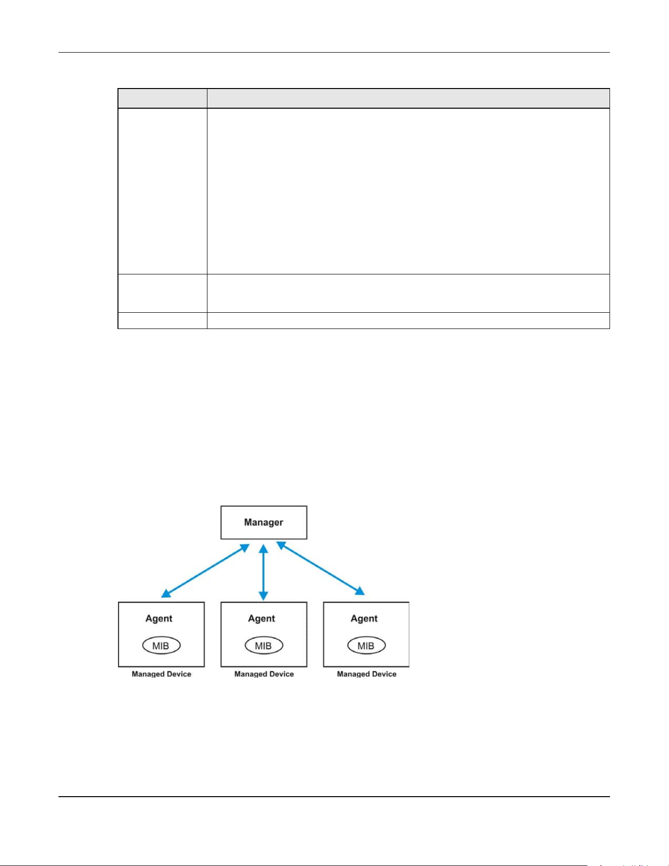
Chapter 80 Networked AV Mode
XGS2220 Series User’s Guide
641
80.13 Configure SNMP
Use this screen to configure your SNMP settings. Simple Network Management Protocol (SNMP) is an
application layer protocol used to manage and monitor TCP/IP-based devices. SNMP is used to
exchange management information between the network management system (NMS) and a network
element (NE). A manager station can manage and monitor the Switch through the network through
SNMP version 1 (SNMPv1), SNMP version 2c or SNMP version 3. The next figure illustrates an SNMP
management operation. SNMP is only available if TCP/IP is configured.
Figure 516 SNMP Management Model
An SNMP managed network consists of two main components: agents and a manager.
An agent is a management software module that resides in a managed Switch (the Switch). An agent
translates the local management information from the managed Switch into a form compatible with
SNMP. The manager is the console through which network administrators perform network management
functions. It executes applications that control and monitor managed devices.
Privilege Enter the privilege level for this user. At the time of writing, users may have a privilege level of
0, 3, 13, or 14 representing different configuration rights as shown below.
• 0 – Display basic system information.
• 3 – Display configuration or status.
• 13 – Configure features except for login accounts, SNMP user accounts, the
authentication method sequence and authorization settings, multiple logins, administrator
and enable passwords, and configuration information display.
• 14 – Configure login accounts, SNMP user accounts, the authentication method
sequence and authorization settings, multiple logins, and administrator and enable
passwords, and display configuration information.
Users can run command lines if the session’s privilege level is greater than or equal to the
command’s privilege level. The session privilege initially comes from the privilege of the login
account. For example, if the user has a privilege of 5, he or she can run commands that
requires privilege level of 5 or less but not more.
Apply Click Apply to save your changes to the Switch’s run-time memory. The Switch loses these
changes if it is turned off or loses power, so use the Save link on the top navigation panel to
save your changes to the non-volatile memory when you are done configuring.
Cancel Click Cancel to begin configuring this screen afresh.
Table 334 SYSTEM > Logins (continued)
LABEL DESCRIPTION

Chapter 80 Networked AV Mode
XGS2220 Series User’s Guide
642
The managed devices contain object variables or managed objects that define each piece of
information to be collected about a Switch. Examples of variables include number of packets received,
node port status and so on. A Management Information Base (MIB) is a collection of managed objects.
SNMP allows a manager and agents to communicate for the purpose of accessing these objects.
SNMP itself is a simple request or response protocol based on the manager or agent model. The
manager issues a request and the agent returns responses using the following protocol operations:
SNMP v3 and Security
SNMP v3 enhances security for SNMP management. SNMP managers can be required to authenticate
with agents before conducting SNMP management sessions.
Security can be further enhanced by encrypting the SNMP messages sent from the managers.
Encryption protects the contents of the SNMP messages. When the contents of the SNMP messages are
encrypted, only the intended recipients can read them.
Click SYSTEM> SNMP > SNMP to view the screen as shown.
Figure 517 SYSTEM > SNMP
Note: The string of any field in this screen should not contain [ ? ], [ | ], [ ' ], [ " ] or [ , ].
Table 335 SNMP Commands
LABEL DESCRIPTION
Get Allows the manager to retrieve an object variable from the agent.
GetNext Allows the manager to retrieve the next object variable from a table or list within an agent. In
SNMPv1, when a manager wants to retrieve all elements of a table from an agent, it initiates a
Get operation, followed by a series of GetNext operations.
Set Allows the manager to set values for object variables within an agent.
Trap Used by the agent to inform the manager of some events.
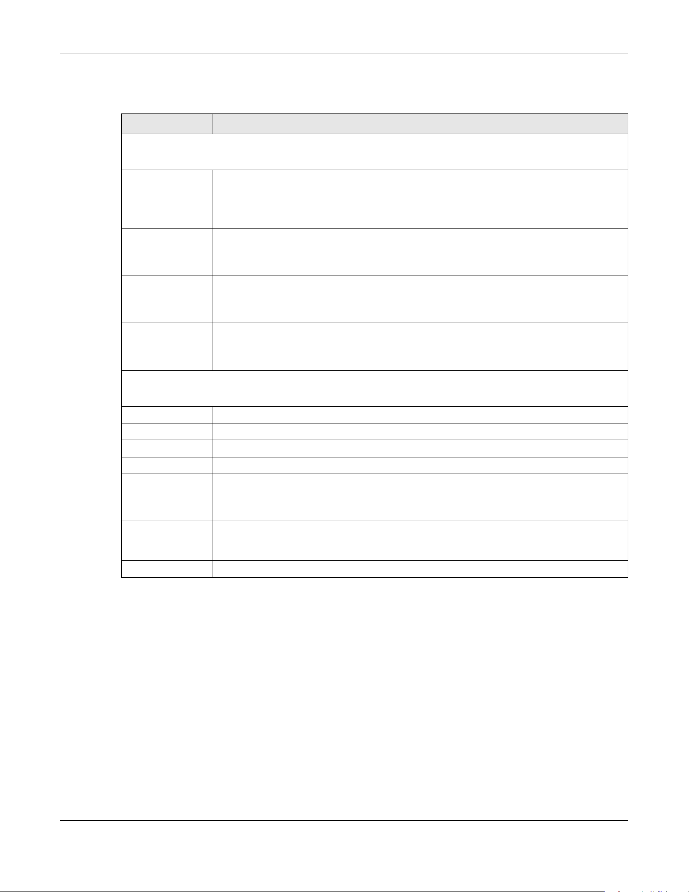
Chapter 80 Networked AV Mode
XGS2220 Series User’s Guide
643
The following table describes the labels in this screen.
80.14 Configure SNMP User
Use this screen to create SNMP users for authentication with managers using SNMP v3 and associate
them to SNMP groups. An SNMP user is an SNMP manager. Click SYSTEM > SNMP > SNMP User to view the
screen as shown.
Table 336 SYSTEM > SNMP
LABEL DESCRIPTION
General Setting
Use this section to specify the SNMP version and community (password) values.
Version Select the SNMP version for the Switch. The SNMP version on the Switch must match the
version on the SNMP manager. Choose SNMP version 2c (v2c), SNMP version 3 (v3) or both
(v3v2c).
SNMP version 2c is backwards compatible with SNMP version 1.
Get Community Enter the Get Community string, which is the password for the incoming Get- and GetNext-
requests from the management station.
The Get Community string is only used by SNMP managers using SNMP version 2c or lower.
Set Community Enter the Set Community string, which is the password for incoming Set- requests from the
management station.
The Set Community string is only used by SNMP managers using SNMP version 2c or lower.
Trap Community Enter the Trap Community string, which is the password sent with each trap to the SNMP
manager.
The Trap Community string is only used by SNMP managers using SNMP version 2c or lower.
Trap Destination
Use this section to configure where to send SNMP traps from the Switch.
Index This is the index of a trap destination.
Version Specify the version of the SNMP trap messages.
IP Enter the IP addresses of up to four managers to send your SNMP traps to.
Port Enter the port number upon which the manager listens for SNMP traps.
Username Enter the user name to be sent to the SNMP manager along with the SNMP v3 trap.
This user name must match an existing account on the Switch (configured in the SYSTEM >
SNMP > SNMP User screen).
Apply Click Apply to save your changes to the Switch’s run-time memory. The Switch loses these
changes if it is turned off or loses power, so use the Save link on the top navigation panel to
save your changes to the non-volatile memory when you are done configuring.
Cancel Click Cancel to begin configuring this screen afresh.

Chapter 80 Networked AV Mode
XGS2220 Series User’s Guide
644
Figure 518 SYSTEM > SNMP > SNMP User
The following table describes the labels in this screen.
80.14.1 Add/Edit SNMP User
Use this screen to create SNMP users for authentication with managers using SNMP v3 and associate
them to SNMP groups. An SNMP user is an SNMP manager. Click Add/Edit, or select an entry and click
Add/Edit in the SYSTEM > SNMP > SNMP User screen to view this screen.
Note: Use the user name and password of the login accounts you specify in this screen to
create accounts on the SNMP v3 manager.
Figure 519 SYSTEM > SNMP > SNMP User > Add/Edit
Note: The input string of any field in this screen should not contain [ ? ], [ | ], [ ' ], [ " ], or [ , ].
Table 337 SYSTEM > SNMP > SNMP User
LABEL DESCRIPTION
Index This is a read-only number identifying a login account on the Switch.
Username This field displays the user name of a login account on the Switch.
Security Level This field displays whether you want to implement authentication and/or encryption for SNMP
communication with this user.
Authentication This field displays the authentication algorithm used for SNMP communication with this user.
Privacy This field displays the encryption method used for SNMP communication with this user.
Group This field displays the SNMP group to which this user belongs.
Select an entry’s check box to select a specific entry. Otherwise, select the check box in the
table heading row to select all entries.
Add/Edit Click Add/Edit to add a new entry or edit a selected one.
Delete Click Delete to remove the selected entries.

Chapter 80 Networked AV Mode
XGS2220 Series User’s Guide
645
The following table describes the labels in this screen.
80.15 Configure SNMP Trap Group
Use this screen to specify the types of SNMP traps that should be sent to each SNMP manager. Click
SYSTEM > SNMP > SNMP Trap Group to view the screen as shown.
Table 338 SYSTEM > SNMP > SNMP User > Add/Edit
LABEL DESCRIPTION
Username Specify the user name of a login account on the Switch. You can enter up to 32 printable
ASCII characters.
Security Level Select whether you want to implement authentication and/or encryption for SNMP
communication from this user. Choose:
• no auth – to use the user name as the password string to send to the SNMP manager. This is
equivalent to the Get, Set and Trap Community in SNMP v2c. This is the lowest security
level.
• auth – to implement an authentication algorithm for SNMP messages sent by this user.
• priv – to implement authentication and encryption for SNMP messages sent by this user.
This is the highest security level.
Note: The settings on the SNMP manager must be set at the same security level or
higher than the security level settings on the Switch.
Authentication Select an authentication algorithm. MD5 (Message Digest 5) and SHA (Secure Hash Algorithm)
are hash algorithms used to authenticate SNMP data. SHA authentication is generally
considered stronger than MD5, but is slower.
Password Enter the password of up to 32 printable ASCII characters (except [ ? ], [ | ], [ ' ], [ " ], [ space ],
or [ , ]) for SNMP user authentication.
Privacy Specify the encryption method for SNMP communication from this user. You can choose one
of the following:
• DES – Data Encryption Standard is a widely used (but breakable) method of data
encryption. It applies a 56-bit key to each 64-bit block of data.
• AES – Advanced Encryption Standard is another method for data encryption that also
uses a secret key. AES applies a 128-bit key to 128-bit blocks of data.
Password Enter the password of up to 32 printable ASCII characters (except [ ? ], [ | ], [ ' ], [ " ], [ space ],
or [ , ]) for encrypting SNMP packets.
Group SNMP v3 adopts the concept of View-based Access Control Model (VACM) group. SNMP
managers in one group are assigned common access rights to MIBs. Specify in which SNMP
group this user is.
admin – Members of this group can perform all types of system configuration, including the
management of administrator accounts.
read-write – Members of this group have read and write rights, meaning that the user can
create and edit the MIBs on the Switch, except the user account and AAA configuration.
read-only – Members of this group have read rights only, meaning the user can collect
information from the Switch.
Apply Click Apply to save your changes to the Switch’s run-time memory. The Switch loses these
changes if it is turned off or loses power, so use the Save link on the top navigation panel to
save your changes to the non-volatile memory when you are done configuring.
Clear Click Clear to clear the fields to the factory defaults.
Cancel Click Cancel to not save the configuration you make and return to the last screen.
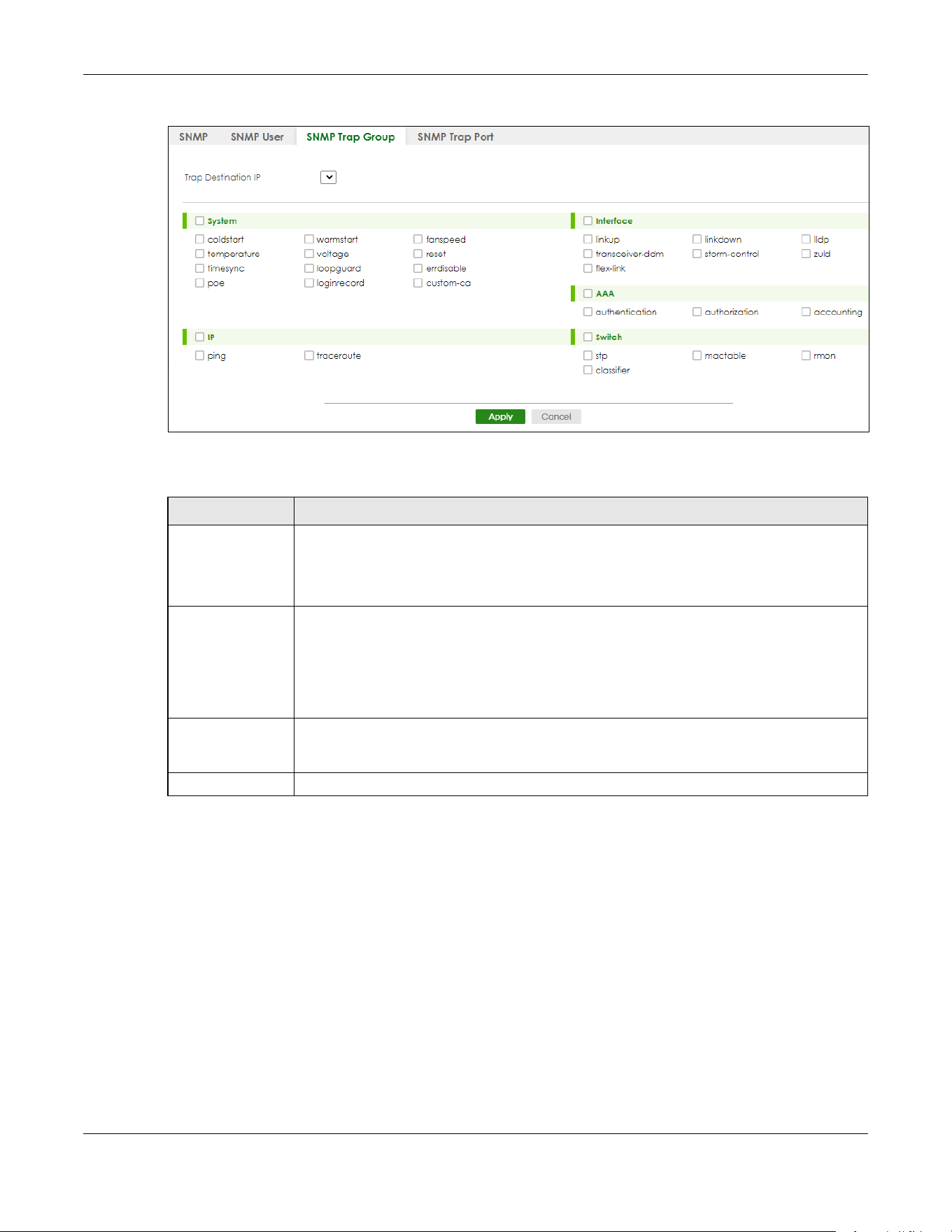
Chapter 80 Networked AV Mode
XGS2220 Series User’s Guide
646
Figure 520 SYSTEM > SNMP > SNMP Trap Group
The following table describes the labels in this screen.
80.16 Enable or Disable Sending of SNMP Traps on a Port
Click SYSTEM > SNMP > SNMP Trap Port to view the screen as shown. Use this screen to set whether a trap
received on the ports would be sent to the SNMP manager.
Table 339 SYSTEM > SNMP > SNMP Trap Group
LABEL DESCRIPTION
Trap Destination IP Select one of your configured trap destination IP addresses. These are the IP addresses of the
SNMP managers. You must first configure a trap destination IP address in the SYSTEM > SNMP >
SNMP screen.
Use the rest of the screen to select which traps the Switch sends to that SNMP manager.
Select the individual SNMP traps that the Switch is to send to the SNMP station.
The traps are grouped by category. Selecting a category in the heading row automatically
selects all of the SNMP traps under that category. Clear the check boxes for individual traps
that you do not want the Switch to send to the SNMP station. Clearing a category’s check
box automatically clears all of the category’s trap check boxes (the Switch only sends traps
from selected categories).
Apply Click Apply to save your changes to the Switch’s run-time memory. The Switch loses these
changes if it is turned off or loses power, so use the Save link on the top navigation panel to
save your changes to the non-volatile memory when you are done configuring.
Cancel Click Cancel to begin configuring this screen afresh.

Chapter 80 Networked AV Mode
XGS2220 Series User’s Guide
647
Figure 521 SYSTEM > SNMP > SNMP Trap Port
The following table describes the labels in this screen.
80.17 PORT
The following sections introduce the PORT screens.
Table 340 SYSTEM > SNMP > SNMP Trap Port
LABEL DESCRIPTION
Options Select the trap type you want to configure here.
Port This field displays a port number.
* Settings in this row apply to all ports.
Use this row only if you want to make some of the settings the same for all ports. Use this row
first to set the common settings and then make adjustments on a port-by-port basis.
Changes in this row are copied to all the ports as soon as you make them.
Active Select this check box to enable the trap type of SNMP traps on this port. The Switch sends the
related traps received on this port to the SNMP manager.
Clear this check box to disable the sending of SNMP traps on this port.
Apply Click Apply to save your changes to the Switch’s run-time memory. The Switch loses these
changes if it is turned off or loses power, so use the Save link on the top navigation panel to
save your changes to the non-volatile memory when you are done configuring.
Cancel Click Cancel to begin configuring this screen afresh.
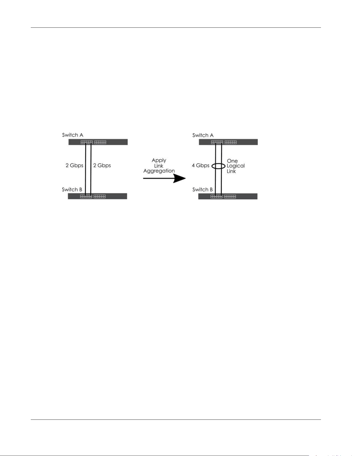
Chapter 80 Networked AV Mode
XGS2220 Series User’s Guide
648
80.18 Link Aggregation
This section shows you how to logically aggregate physical links to form one logical, higher-bandwidth
link.
Link aggregation (trunking) is the grouping of physical ports into one logical higher-capacity link. You
may want to trunk ports if for example, it is cheaper to use multiple lower-speed links than to under-utilize
a high-speed, but more costly, single-port link. However, the more ports you aggregate then the fewer
available ports you have. A trunk group is one logical link containing multiple ports.
The beginning port of each trunk group must be physically connected to form a trunk group.
Figure 522 Link Aggregation
80.18.1 What You Can Do
• Use the Link Aggregation Status screen (Section 80.19 on page 648) to view ports you have
configured to be in the trunk group, ports that are currently transmitting data as one logical link in the
trunk group and so on.
• Use the Link Aggregation Setting screen (Section 80.20 on page 650) to configure to enable static link
aggregation.
• Use the Link Aggregation Control Protocol screen (Section 80.21 on page 651) to enable Link
Aggregation Control Protocol (LACP).
80.19 Link Aggregation Status
Use the Link Aggregation Status screen to view ports you have configured to be in the trunk group, ports
that are currently transmitting data as one logical link in the trunk group and so on.
Click PORT > Link Aggregation > Link Aggregation Status in the navigation panel to display the screen as
shown.
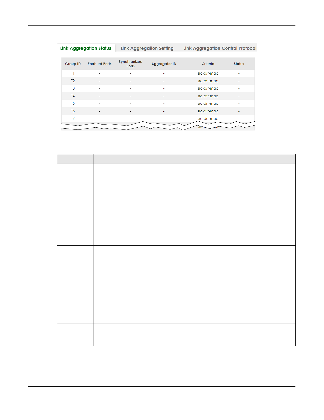
Chapter 80 Networked AV Mode
XGS2220 Series User’s Guide
649
Figure 523 PORT > Link Aggregation > Link Aggregation Status
The following table describes the labels in this screen.
Table 341 PORT > Link Aggregation > Link Aggregation Status
LABEL DESCRIPTION
Group ID This field displays the group ID to identify a trunk group, that is, one logical link containing multiple
ports.
Enabled Ports These are the ports you have configured in the Link Aggregation Setting screen to be in the trunk
group.
The port numbers displays only when this trunk group is activated and there is a port belonging to
this group.
Synchronized
Ports
These are the ports that are currently transmitting data as one logical link in this trunk group.
Aggregator ID Link Aggregator ID consists of the following: system priority, MAC address, key, port priority and
port number.
The ID displays only when there is a port belonging to this trunk group and LACP is also enabled
for this group.
Criteria This shows the outgoing traffic distribution algorithm used in this trunk group. Packets from the
same source and/or to the same destination are sent over the same link within the trunk.
src-mac means the Switch distributes traffic based on the packet’s source MAC address.
dst-mac means the Switch distributes traffic based on the packet’s destination MAC address.
src-dst-mac means the Switch distributes traffic based on a combination of the packet’s source
and destination MAC addresses.
src-ip means the Switch distributes traffic based on the packet’s source IP address.
dst-ip means the Switch distributes traffic based on the packet’s destination IP address.
src-dst-ip means the Switch distributes traffic based on a combination of the packet’s source
and destination IP addresses.
Status This field displays how these ports were added to the trunk group. It displays:
• Static – if the ports are configured as static members of a trunk group.
• LACP – if the ports are configured to join a trunk group through LACP.
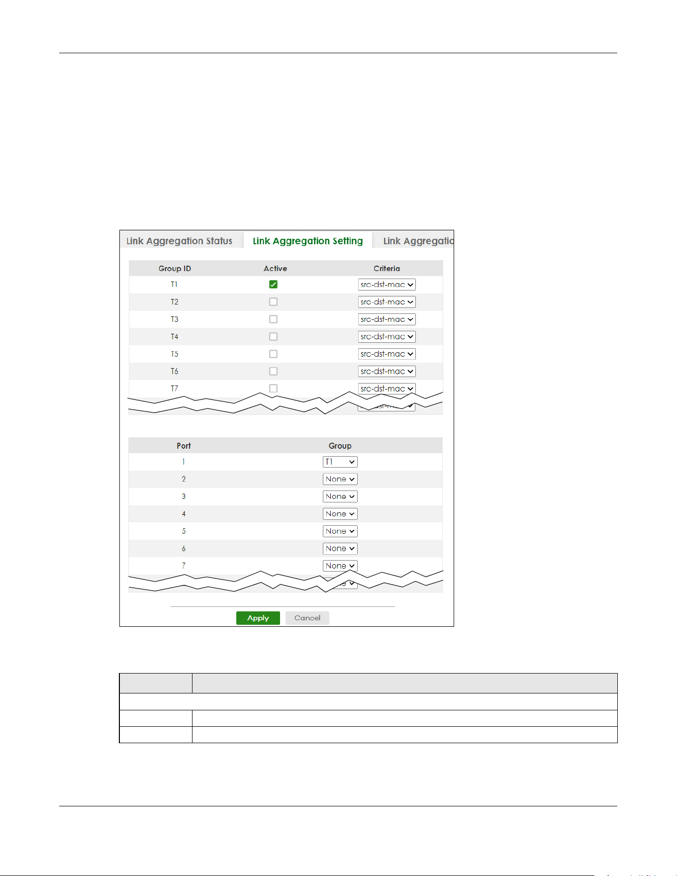
Chapter 80 Networked AV Mode
XGS2220 Series User’s Guide
650
80.20 Link Aggregation Setting
Use the Link Aggregation Setting screen to enable static link. Link aggregation (trunking) is the grouping
of physical ports into one logical higher-capacity link. You may want to trunk ports if for example, it is
cheaper to use multiple lower-speed links than to under-utilize a high-speed, but more costly, single-port
link. However, the more ports you aggregate then the fewer available ports you have. A trunk group is
one logical link containing multiple ports.
Click PORT > Link Aggregation > Link Aggregation Setting to display the screen shown next.
Figure 524 PORT > Link Aggregation > Link Aggregation Setting
The following table describes the labels in this screen.
Table 342 PORT> Link Aggregation > Link Aggregation Setting
LABEL DESCRIPTION
This is the only screen you need to configure to enable static link aggregation.
Group ID The field identifies the link aggregation group, that is, one logical link containing multiple ports.
Active Select this to activate a trunk group.

Chapter 80 Networked AV Mode
XGS2220 Series User’s Guide
651
80.21 Link Aggregation Control Protocol
When you enable LACP link aggregation on a port, the port can automatically negotiate with the ports
at the remote end of a link to establish trunk groups. LACP also allows port redundancy, that is, if an
operational port fails, then one of the “standby” ports become operational without user intervention.
Click PORT > Link Aggregation > Link Aggregation Control Protocol to display the screen shown next.
Note: Do NOT configure this screen unless you want to enable dynamic link aggregation.
Criteria Select the outgoing traffic distribution type. Packets from the same source and/or to the same
destination are sent over the same link within the trunk. By default, the Switch uses the src-dst-mac
distribution type. If the Switch is behind a router, the packet’s destination or source MAC address
will be changed. In this case, set the Switch to distribute traffic based on its IP address to make
sure port trunking can work properly.
Select src-mac to distribute traffic based on the packet’s source MAC address.
Select dst-mac to distribute traffic based on the packet’s destination MAC address.
Select src-dst-mac to distribute traffic based on a combination of the packet’s source and
destination MAC addresses.
Select src-ip to distribute traffic based on the packet’s source IP address.
Select dst-ip to distribute traffic based on the packet’s destination IP address.
Select src-dst-ip to distribute traffic based on a combination of the packet’s source and
destination IP addresses.
Port This field displays the port number.
Group Select the trunk group to which a port belongs.
Note: When you enable the port security feature on the Switch and configure port
security settings for a port, you cannot include the port in an active trunk group.
Apply Click Apply to save your changes to the Switch’s run-time memory. The Switch loses these
changes if it is turned off or loses power, so use the Save link on the top navigation panel to save
your changes to the non-volatile memory when you are done configuring.
Cancel Click Cancel to begin configuring this screen afresh.
Table 342 PORT> Link Aggregation > Link Aggregation Setting (continued)
LABEL DESCRIPTION

Chapter 80 Networked AV Mode
XGS2220 Series User’s Guide
652
Figure 525 PORT > Link Aggregation > Link Aggregation Control Protocol
The following table describes the labels in this screen.
Table 343 PORT > Link Aggregation > Link Aggregation Control Protocol
LABEL DESCRIPTION
Active Enable the switch button to enable Link Aggregation Control Protocol (LACP).
System Priority LACP system priority is a number between 1 and 65535. The switch with the lowest system priority
(and lowest port number if system priority is the same) becomes the LACP “server”. The LACP
“server” controls the operation of LACP setup. Enter a number to set the priority of an active port
using Link Aggregation Control Protocol (LACP). The smaller the number, the higher the priority
level.
Use this section to enable LACP on trunks.
Group ID The field identifies the link aggregation group, that is, one logical link containing multiple ports.
LACP Active Select this option to enable LACP for a trunk.
Use this section to configure LACP timeout on ports.
Port This field displays the port number.

Chapter 80 Networked AV Mode
XGS2220 Series User’s Guide
653
80.22 PoE Status
A powered device (PD) is a device such as an access point or a switch, that supports PoE (Power over
Ethernet) so that it can receive power from another device through an Ethernet port.
You can also set priorities so that the Switch is able to reserve and allocate power to certain PDs.
Note: The PoE (Power over Ethernet) devices that supply or receive power and their
connected Ethernet cables must all be completely indoors.
Figure 526 PoE Example Application
To view the current amount of power that PDs are receiving from the Switch, click PORT > PoE Setup >
PoE Status.
* Settings in this row apply to all ports.
Use this row only if you want to make some settings the same for all ports. Use this row first to set
the common settings and then make adjustments on a port-by-port basis.
Note: Changes in this row are copied to all the ports as soon as you make them.
LACP Timeout Timeout is the time interval between the individual port exchanges of LACP packets in order to
check that the peer port in the trunk group is still up. If a port does not respond after three tries,
then it is deemed to be “down” and is removed from the trunk. Set a short timeout (1 second) for
busy trunked links to ensure that disabled ports are removed from the trunk group as soon as
possible.
Select either 1 second or 30 seconds.
Apply Click Apply to save your changes to the Switch’s run-time memory. The Switch loses these
changes if it is turned off or loses power, so use the Save link on the top navigation panel to save
your changes to the non-volatile memory when you are done configuring.
Cancel Click Cancel to begin configuring this screen afresh.
Table 343 PORT > Link Aggregation > Link Aggregation Control Protocol (continued)
LABEL DESCRIPTION

Chapter 80 Networked AV Mode
XGS2220 Series User’s Guide
654
Figure 527 PORT > PoE Setup > PoE Status
The following table describes the labels in this screen.
Table 344 PORT > PoE Setup > PoE Status
LABEL DESCRIPTION
PoE Mode This field displays the power management mode used by the Switch, whether it is in
Classification or Consumption mode.
Total Power (W) This field displays the total power the Switch can provide to the connected PoE-enabled
devices on the PoE ports.
PoE Usage (%) This field displays the amount of power currently being supplied to connected PoE devices (PDs)
as a percentage of the total PoE power the Switch can supply.
When PoE usage reaches 100%, the Switch will shut down PDs one-by-one according to the PD
priority which you configured in PORT > PoE Setup > PoE Setup.
Consuming
Power (W)
This field displays the amount of power the Switch is currently supplying to the connected PoE-
enabled devices.
Allocated Power
(W)
This field displays the total amount of power the Switch (in classification mode) has reserved for
PoE after negotiating with the connected PoE devices. It shows NA when the Switch is in
consumption mode.
Consuming Power (W) can be less than or equal but not more than the Allocated Power (W).
Remaining
Power (W)
This field displays the amount of power the Switch can still provide for PoE.
Note: The Switch must have at least 16 W of remaining power in order to supply
power to a PoE device, even if the PoE device needs less than 16 W.
Port This is the port index number.
State This field shows which ports can receive power from the Switch. You can set this in Section 80.23
on page 655.
• Disable – The PD connected to this port cannot get power supply.
• Enable – The PD connected to this port can receive power.
Chapter 80 Networked AV Mode
XGS2220 Series User’s Guide
655
80.23 PoE Setup
Use this screen to set the PoE power management mode, priority levels, power-up mode and the
maximum amount of power for the connected PDs.
Click PORT > PoE Setup > PoE Setup, the following screen opens.
Class This shows the power classification of the PD. Each PD has a specified maximum power that fall
under one of the classes.
The Class is a number from 0 to 6, where each value represents the range of power that the
Switch provides to the PD.
Each class corresponds to a default maximum power that can be extended in Port > PoE Setup
> PoE Setup to the following values.
• Class 0 – default: 0.44 W to 15.4 W.
• Class 1 – default: 0.44 W to 4 W.
• Class 2 – default: 0.44 W to 7 W.
• Class 3 – default: 0.44 W to 15.4 W.
• Class 4 – default: 0.44 W to 30 W.
• Class 5 – default: 0.44 W to 45 W.
• Class 6 – default: 0.44 W to 60 W.
Priority When the total power requested by the PDs exceeds the total PoE power budget on the Switch,
you can set the PD priority to allow the Switch to provide power to ports with higher priority first.
• Critical has the highest priority.
• High has the Switch assign power to the port after all critical priority ports are served.
• Low has the Switch assign power to the port after all critical and high priority ports are
served.
Power-Up This field displays the PoE standard the Switch uses to provide power on this port.
Consuming
Power (W)
This field displays the current amount of power consumed by the PD from the Switch on this port.
Max Power (W) This field displays the maximum amount of power the PD could use from the Switch on this port.
Table 344 PORT > PoE Setup > PoE Status (continued)
LABEL DESCRIPTION

Chapter 80 Networked AV Mode
XGS2220 Series User’s Guide
656
Figure 528 PORT > PoE Setup > PoE Setup
The following table describes the labels in this screen.
Table 345 Port > PoE Setup > PoE Setup
LABEL DESCRIPTION
PoE Mode Select the power management mode you want the Switch to use.
• Classification – Select this if you want the Switch to reserve the maximum power for each PD
according to the PD’s power class and priority level. If the total power supply runs out, PDs
with lower priority do not get power to function. In this mode, the maximum power is reserved
based on what you configure in Max Power or the standard power limit for each class.
• Consumption – Select this if you want the Switch to supply the actual power that the PD
needs. The Switch also allocates power based on a port’s Max Power and the PD’s power
class and priority level. The Switch puts a limit on the maximum amount of power the PD can
request and use. In this mode, the default maximum power that can be delivered to the PD is
33 W (IEEE 802.3at Class 4) or 22 W (IEEE 802.3af Classes 0 to 3).
Continuous
PoE
Select ON to guarantee continuous power supply to the connected PDs while the Switch is
restarting after a warm reboot. The Switch will NOT perform a power cycle on the connected PDs.
If you do a cold reboot, the Switch also restarts the connected PDs.
Port This is the port index number.
* Settings in this row apply to all ports.
Use this row only if you want to make some settings the same for all ports. Use this row first to set
the common settings and then make adjustments on a port-by-port basis.
Changes in this row are copied to all the ports as soon as you make them.
Active Select this to provide power to a PD connected to the port.
If left unchecked, the PD connected to the port cannot receive power from the Switch.

Chapter 80 Networked AV Mode
XGS2220 Series User’s Guide
657
Priority When the total power requested by the PDs exceeds the total PoE power budget on the Switch,
you can set the PD priority to allow the Switch to provide power to ports with higher priority.
Select Critical to give the highest PD priority on the port.
Select High to set the Switch to assign the remaining power to the port after all critical priority
ports are served.
Select Low to set the Switch to assign the remaining power to the port after all critical and high
priority ports are served.
Power-Up Set how the Switch provides power to a connected PD at power-up.
802.3af – the Switch follows the IEEE 802.3af Power over Ethernet standard to supply power to the
connected PDs during power-up.
Legacy – the Switch can provide power to the connected PDs that require high inrush currents at
power-up. Inrush current is the maximum, instantaneous input current drawn by the PD when first
turned on.
Pre-802.3at – the Switch initially offers power on the port according to the IEEE 802.3af standard,
and then switches to support the IEEE 802.3at standard within 75 milliseconds after a PD is
connected to the port. Select this option if the Switch is performing 2-event Layer-1 classification
(PoE+ hardware classification) or the connected PD is NOT performing Layer 2 power
classification using Link Layer Discovery Protocol (LLDP).
802.3at – the Switch supports the IEEE 802.3at High Power over Ethernet standard and can supply
power of up to 30 W per Ethernet port. IEEE 802.3at is also known as PoE+ or PoE Plus. An IEEE
802.3at compatible device is referred to as Type 2. Power Class 4 (High Power) can only be used
by Type 2 devices. If the connected PD requires a Class 4 current when it is turned on, it will be
powered up in this mode.
Force-802.3at – the Switch offers power of up to 33 W on the port without performing PoE
hardware classification. Select this option if the connected PD does not comply with any PoE
standard and requests power higher than a standard power limit.
Pre-802.3bt – the Switch offers power on the port according to the IEEE 802.3bt standard. Select
this option if the connected PD was developed before the IEEE 802.3bt standard is implemented
but requires power between 33 W and 60 W. IEEE 802.3bt is also known as PoE++ or PoE Plus Plus.
802.3bt – the Switch supports the IEEE 802.3bt standard and can supply power of up to 60 W per
Ethernet port to the connected PDs at power-up.
Max Power
(mW)
Specify the maximum amount of power the PD could use from the Switch on this port. If you leave
this field blank, the Switch refers to the standard or default maximum power for each class.
LLDP Power Via
MDI
Select this to have the Switch negotiate PoE power with the PD connected to the port by
transmitting LLDP Power Via MDI TLV frames. This helps the Switch allocate less power to the PD on
this port. The connected PD must be able to request PoE power through LLDP.
The Power Via MDI TLV allows PoE devices to advertise and discover the MDI power support
capabilities of the sending port on the remote device.
•Port Class
• MDI Supported
•MDI Enabled
• Pair Controllable
• PSE Power Pairs
•Power Class
Apply Click Apply to save your changes to the Switch’s run-time memory. The Switch loses these
changes if it is turned off or loses power, so use the Save link on the top navigation panel to save
your changes to the non-volatile memory when you are done configuring.
Cancel Click Cancel to begin configuring this screen afresh.
Table 345 Port > PoE Setup > PoE Setup (continued)
LABEL DESCRIPTION
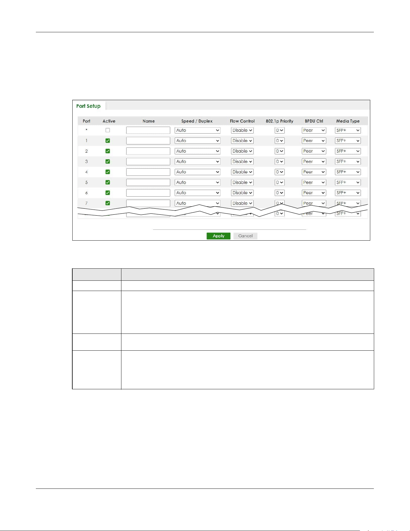
Chapter 80 Networked AV Mode
XGS2220 Series User’s Guide
658
80.24 Port Setup
Use this screen to configure Switch port settings. Click PORT > Port Setup in the navigation panel to
display the configuration screen.
Figure 529 PORT > Port Setup
The following table describes the labels in this screen.
Table 346 PORT > Port Setup
LABEL DESCRIPTION
Port This is the port index number.
* Settings in this row apply to all ports.
Use this row only if you want to make some settings the same for all ports. Use this row first to set
the common settings and then make adjustments on a port-by-port basis.
Note: Changes in this row are copied to all the ports as soon as you make them.
Active Select this check box to enable a port. The factory default for all ports is enabled. A port must
be enabled for data transmission to occur.
Name Type a descriptive name that identifies this port. You can enter up to 128 printable ASCII
characters except [ ? ], [ | ], [ ' ] or [ " ].
Note: Due to space limitations, the port name may be truncated in some Web
Configurator screens.

Chapter 80 Networked AV Mode
XGS2220 Series User’s Guide
659
Speed/Duplex Select the speed and the duplex mode of the Ethernet connection on this port. The choices are
Auto, Auto-1G, 10-an (10M/auto-negotiation), 10M / Full Duplex, 100-an (100M/auto-
negotiation), 2.5G / Full Duplex, 5G / Full Duplex, and 100M / Full Duplex for a 100Base-T
connection. 1G / Full Duplex is supported by both 1000Base-T and 1000Base-X connections. 10G
/ Full Duplex is supported by the 10 Gigabit Ethernet connections on the Switch that has a 10
Gigabit interface.
Selecting Auto-1G or Auto (auto-negotiation) allows one port to negotiate with a peer port
automatically to obtain the connection speed and duplex mode that both ends support. When
auto-negotiation is turned on, a port on the Switch negotiates with the peer automatically to
determine the connection speed and duplex mode. If the peer port does not support auto-
negotiation or turns off this feature, the Switch determines the connection speed by detecting
the signal on the cable and using half duplex mode. When the Switch’s auto-negotiation is
turned off, a port uses the pre-configured speed and duplex mode when making a connection,
thus requiring you to make sure that the settings of the peer port are the same in order to
connect.
Flow Control A concentration of traffic on a port decreases port bandwidth and overflows buffer memory
causing packet discards and frame losses. Flow Control is used to regulate transmission of signals
to match the bandwidth of the receiving port.
The Switch uses IEEE 802.3x flow control in full duplex mode and backpressure flow control in half
duplex mode.
IEEE 802.3x flow control is used in full duplex mode to send a pause signal to the sending port,
causing it to temporarily stop sending signals when the receiving port memory buffers fill.
Back Pressure flow control is typically used in half duplex mode to send a "collision" signal to the
sending port (mimicking a state of packet collision) causing the sending port to temporarily stop
sending signals and resend later.
Select Tx Rx to allow the Switch port to send pause signal to the connected device, and for the
connected device to send a pause signal to the Switch. The Switch will temporarily stop sending
signals after receiving pause signal.
Select Tx to allow the Switch port to send pause signal to the connected device.
Select Rx to allow the connected device to send a pause signal to the Switch. The Switch will
temporarily stop sending signals.
Otherwise, select Disable.
802.1p Priority This priority value is added to incoming frames without a (802.1p) tag.
BPDU Ctrl Configure the way to treat BPDUs received on this port. You must activate Bridging Control
Protocol Transparency in the SYSTEM > Switch Setup screen first.
Select Peer to process any BPDU (Bridge Protocol Data Units) received on this port.
Select Tunnel
to forward BPDUs received on this port.
Select Discard to drop any BPDU received on this port.
Select Network to process a BPDU with no VLAN tag and forward a tagged BPDU.
Media Type You can insert either an SFP+ transceiver or an SFP+ Direct Attach Copper (DAC) cable into the
10 Gigabit interface of the Switch.
Select the media type (SFP+ or DAC10G) of the SFP+ module that is attached to the 10 Gigabit
interface.
Apply Click Apply to save your changes to the Switch’s run-time memory. The Switch loses these
changes if it is turned off or loses power, so use the Save link on the top navigation panel to save
your changes to the non-volatile memory when you are done configuring.
Cancel Click Cancel to begin configuring this screen afresh.
Table 346 PORT > Port Setup (continued)
LABEL DESCRIPTION

Chapter 80 Networked AV Mode
XGS2220 Series User’s Guide
660
80.25 SWITCHING
The following sections introduce the SWITCHING screens.
80.26 Port Mirroring
Port mirroring allows you to copy a traffic flow to a monitor port (the port you copy the traffic to) in order
that you can examine the traffic from the monitor port without interference.
Click SWITCHING > Mirroring in the navigation panel to display the Mirroring screen. Use this screen to
select a monitor port and specify the traffic flow to be copied to the monitor port.
Figure 530 SWITCHING > Mirroring
The following table describes the labels in this screen.
Table 347 SWITCHING > Mirroring
LABEL DESCRIPTION
Active Enable the switch button to activate port mirroring on the Switch. Disable the switch to disable the
feature.
Monitor
Port
The monitor port is the port you copy the traffic to in order to examine it in more detail without
interfering with the traffic flow on the original ports. Type the port number of the monitor port.
In Stacking mode, the first box field is the slot ID and the second field is the port number.
Port This field displays the port number.

Chapter 80 Networked AV Mode
XGS2220 Series User’s Guide
661
80.27 Multicast
Traditionally, IP packets are transmitted in one of either two ways – Unicast (1 sender to 1 recipient) or
Broadcast (1 sender to everybody on the network). Multicast delivers IP packets to just a group of hosts
on the network.
IGMP (Internet Group Management Protocol) is a network-layer protocol used to establish membership
in a multicast group
– it is not used to carry user data. Refer to RFC 1112, RFC 2236 and RFC 3376 for
information on IGMP versions 1, 2 and 3 respectively.
This section shows you how to configure various multicast features.
80.27.1 What You Can Do
• Use the IPv4 Multicast Status screen (Section 80.28 on page 661) to view multicast group information.
• Use the IGMP Snooping screen (Section 80.29 on page 662) to enable IGMP snooping to forward
group multicast traffic only to ports that are members of that group.
• Use the IGMP Snooping VLAN screen (Section 80.30 on page 666) to perform IGMP snooping on up to
16 VLANs.
• Use the IGMP Filtering Profile screen (Section 80.31 on page 668) to specify a range of multicast
groups that clients connected to the Switch are able to join.
80.28 IPv4 Multicast Status
Click SWITCHING > Multicast > IPv4 Multicast Status to display the screen as shown. This screen shows the
IPv4 multicast group information.
* Settings in this row apply to all ports.
Use this row only if you want to make some settings the same for all ports. Use this row first to set the
common settings and then make adjustments on a port-by-port basis.
Note: Changes in this row are copied to all the ports as soon as you make them.
Mirrored Select this option to mirror the traffic on a port.
Direction Specify the direction of the traffic to mirror by selecting from the drop-down list box. Choices are
Egress (outgoing), Ingress (incoming) and Both.
Apply Click Apply to save your changes to the Switch’s run-time memory. The Switch loses these changes if
it is turned off or loses power, so use the Save link on the top navigation panel to save your changes
to the non-volatile memory when you are done configuring.
Cancel Click Cancel to reset the fields.
Table 347 SWITCHING > Mirroring (continued)
LABEL DESCRIPTION
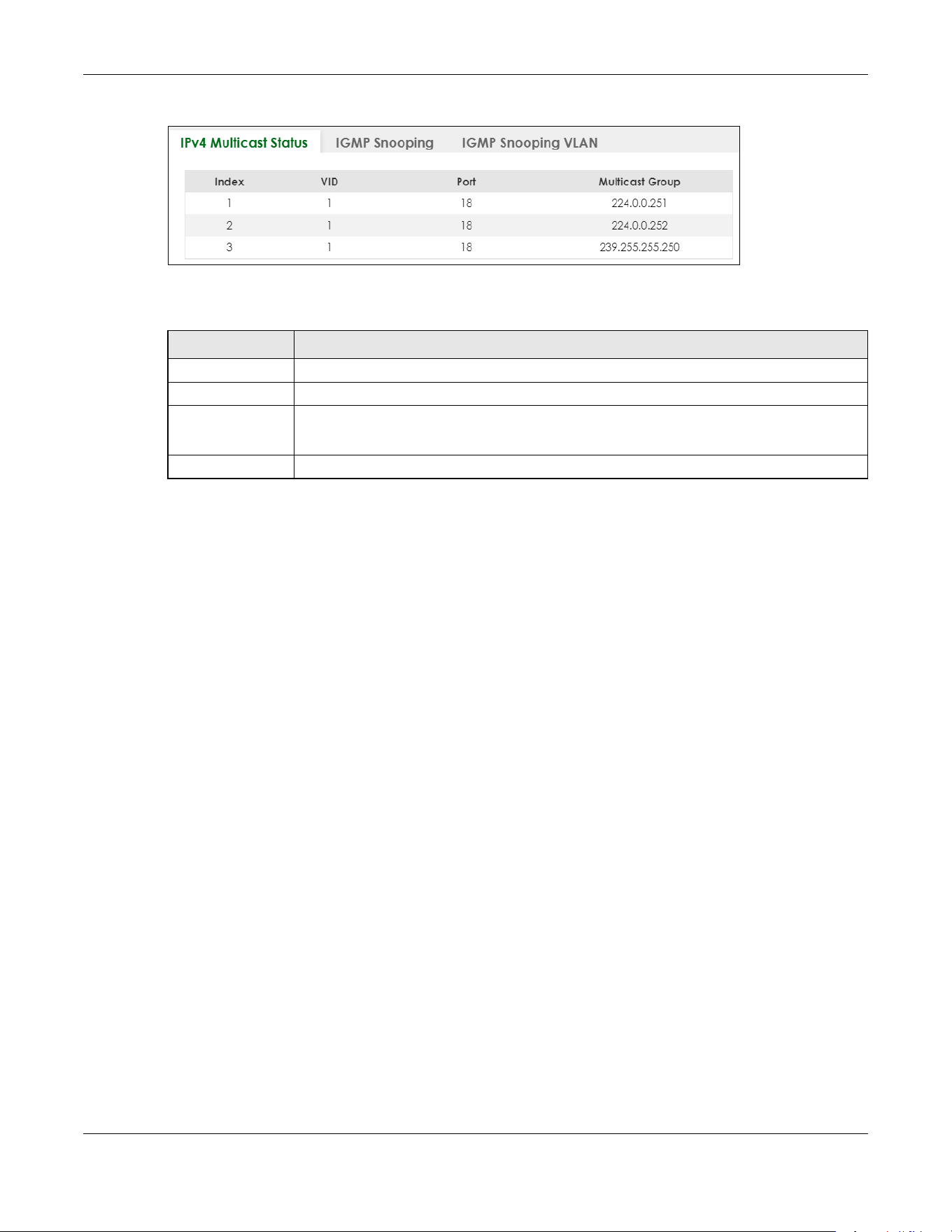
Chapter 80 Networked AV Mode
XGS2220 Series User’s Guide
662
Figure 531 SWITCHING > Multicast > IPv4 Multicast Status
The following table describes the labels in this screen.
80.29 IGMP Snooping
A Switch can passively snoop on IGMP packets transferred between IP multicast routers or switches and
IP multicast hosts to learn the IP multicast group membership. It checks IGMP packets passing through it,
picks out the group registration information, and configures multicasting accordingly. IGMP snooping
allows the Switch to learn multicast groups without you having to manually configure them.
The Switch forwards multicast traffic destined for multicast groups (that it has learned from IGMP
snooping or that you have manually configured) to ports that are members of that group. IGMP
snooping generates no additional network traffic, allowing you to significantly reduce multicast traffic
passing through your Switch.
Click SWITCHING > Multicast > IGMP Snooping to display the screen as shown.
Table 348 SWITCHING > Multicast > IPv4 Multicast Status
LABEL DESCRIPTION
Index This is the index number of the entry.
VID This field displays the multicast VLAN ID.
Port This field displays the port number that belongs to the multicast group.
In Stacking mode, the first number represents the slot and the second is the port number.
Multicast Group This field displays IP multicast group addresses.

Chapter 80 Networked AV Mode
XGS2220 Series User’s Guide
663
Figure 532 SWITCHING > Multicast > IGMP Snooping
The following table describes the labels in this screen.
Table 349 SWITCHING > Multicast > IGMP Snooping
LABEL DESCRIPTION
Active Enable the switch button to enable IGMP Snooping to forward group multicast traffic only to
ports that are members of that group.
Querier Select this to allow the Switch to send IGMP General Query messages to the VLANs with the
multicast hosts attached.
Querier Version IGMP snooping query works only when both host and Switch support the same IGMP version.
Select v2 to allow the Switch to send IGMPv2 queries only.
Select v3 to allow the Switch to send IGMPv3 queries only.

Chapter 80 Networked AV Mode
XGS2220 Series User’s Guide
664
Report Proxy Select this to allow the Switch to act as the IGMP report proxy and leave proxy. It will report
group changes to a connected multicast router.
The Switch not only checks IGMP packets between multicast routers or switches and multicast
hosts to learn the multicast group membership, but also replaces the source MAC address in
an IGMP v1/v2 report with its own MAC address before forwarding to the multicast router or
switch. When the Switch receives more than one IGMP v1/v2 join report that requests to join
the same multicast group, it only sends a new join report with its MAC address. This helps
reduce the number of multicast join reports passed to the multicast router or switch.
The Switch sends a leave message with its MAC address to the multicast router or switch only
when it receives the leave message from the last host in a multicast group.
Host Timeout Specify the time (from 1 to 16711450) in seconds that elapses before the Switch removes an
IGMP group membership entry if it does not receive report messages from the port.
802.1p Priority Select a priority level (0 – 7) to which the Switch changes the priority in outgoing IGMP control
packets. Otherwise, select No-Change to not replace the priority.
IGMP Filtering
Active
Enable the switch button to enable IGMP filtering to control which IGMP groups a subscriber
on a port can join.
If you enable IGMP filtering, you must create and assign IGMP filtering profiles for the ports that
you want to allow to join multicast groups.
IGMP Snooping
Smart Forward
Active
Enable the switch button to enable sending of multicast frame to querier port and IGMP
subscriber groups. Otherwise, the querier port forwards the frames only when it receives a join
report and it belongs to the IGMP group.
Unknown Multicast
Frame
Specify the action to perform when the Switch receives an unknown multicast frame.
•Select Flooding to send the frames to all ports.
•Select Drop to discard the frames.
•Select Drop on VLAN and enter the VLAN ID numbers to discard the frames on the
specified VLANs. Use a dash to specify consecutive VLANs and a comma (no spaces) to
specify non-consecutive VLANs. For example, 51–53 includes 51, 52 and 53, but 51,53 does
not include 52.
Unknown Multicast
Frame to Querier
Port
Specify the action to perform when Unknown Multicast Frame is set to Drop.
•Select Drop to discard the frames.
•Select Forwarding to send the frames to all querier ports.
•Select Forwarding on VLAN and enter the VLAN ID numbers to send the frames to the ports
which are used as an IGMP query port on the specified VLANs. Use a dash to specify
consecutive VLANs and a comma (no spaces) to specify non-consecutive VLANs. For
example, 51–53 includes 51, 52 and 53, but 51,53 does not include 52.
Reserved Multicast
Group
The IP address range of 224.0.0.0 to 224.0.0.255 are reserved for multicasting on the local
network only. For example, 224.0.0.1 is for all hosts on a local network segment and 224.0.0.9 is
used to send RIP routing information to all RIP v2 routers on the same network segment. A
multicast router will not forward a packet with the destination IP address within this range to
other networks. See the IANA web site for more information.
The layer-2 multicast MAC addresses used by Cisco layer-2 protocols, 01:00:0C:CC:CC:CC
and 01:00:0C:CC:CC:CD, are also included in this group.
Specify the action to perform when the Switch receives a frame with a reserved multicast
address.
•Select Flooding to send the frames to all ports.
•Select Drop to discard the frames.
Use this section to configure IGMP Snooping on each port.
Port This field displays the port number.
Table 349 SWITCHING > Multicast > IGMP Snooping (continued)
LABEL DESCRIPTION

Chapter 80 Networked AV Mode
XGS2220 Series User’s Guide
665
* Settings in this row apply to all ports.
Use this row only if you want to make some settings the same for all ports. Use this row first to set
the common settings and then make adjustments on a port-by-port basis.
Changes in this row are copied to all the ports as soon as you make them.
Immediate Leave Select this option to set the Switch to remove this port from the multicast tree when an IGMP
version 2 leave message is received on this port.
Select this option if there is only one host connected to this port.
Normal Leave Enter an IGMP normal leave timeout value (from 200 to 6348800) in miliseconds. Select this
option to have the Switch use this timeout to update the forwarding table for the port.
In normal leave mode, when the Switch receives an IGMP leave message from a host on a
port, it forwards the message to the multicast router. The multicast router then sends out an
IGMP Group-Specific Query (GSQ) message to determine whether other hosts connected to
the port should remain in the specific multicast group. The Switch forwards the query message
to all hosts connected to the port and waits for IGMP reports from hosts to update the
forwarding table.
This defines how many seconds the Switch waits for an IGMP report before removing an IGMP
snooping membership entry when an IGMP leave message is received on this port from a
host.
Fast Leave Enter an IGMP fast leave timeout value (from 200 to 6348800) in miliseconds. Select this option
to have the Switch use this timeout to update the forwarding table for the port.
In fast leave mode, right after receiving an IGMP leave message from a host on a port, the
Switch itself sends out an IGMP Group-Specific Query (GSQ) message to determine whether
other hosts connected to the port should remain in the specific multicast group. This helps
speed up the leave process.
This defines how many seconds the Switch waits for an IGMP report before removing an IGMP
snooping membership entry when an IGMP leave message is received on this port from a
host.
Group Limited Select this option to limit the number of multicast groups this port is allowed to join.
Max Group
Number
Enter the number of multicast groups this port is allowed to join. Once a port is registered in the
specified number of multicast groups, any new IGMP join report frames is dropped on this
port.
Throttling IGMP throttling controls how the Switch deals with the IGMP reports when the maximum
number of the IGMP groups a port can join is reached.
Select Deny to drop any new IGMP join report received on this port until an existing multicast
forwarding table entry is aged out.
Select Replace to replace an existing entry in the multicast forwarding table with the new
IGMP reports received on this port.
IGMP Filtering
Profile
Select the name of the IGMP filtering profile to use for this port. Otherwise, select Default to
prohibit the port from joining any multicast group.
You can create IGMP filtering profiles in the SWITCHING > Multicast > IGMP Filtering Profile
screen.
Table 349 SWITCHING > Multicast > IGMP Snooping (continued)
LABEL DESCRIPTION
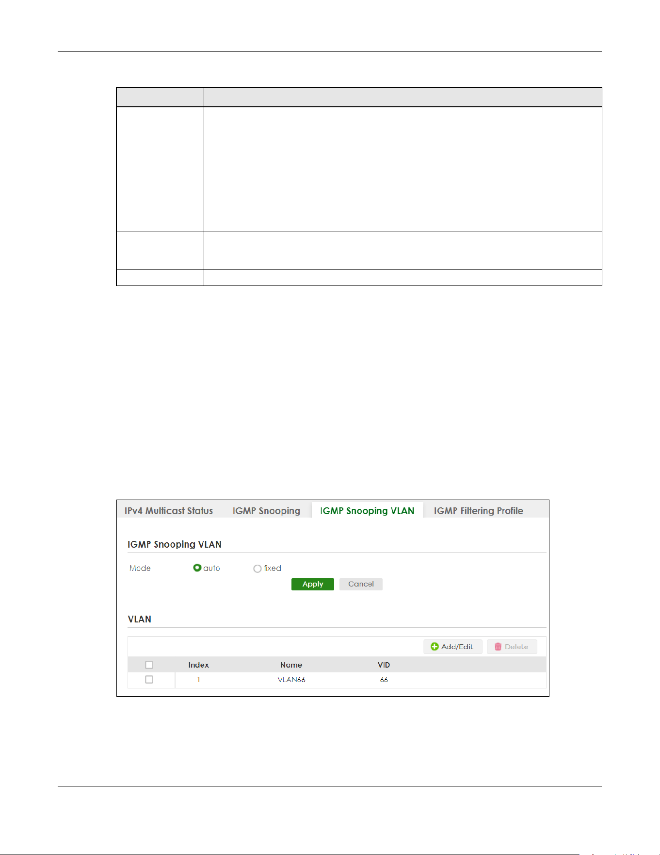
Chapter 80 Networked AV Mode
XGS2220 Series User’s Guide
666
80.30 IGMP Snooping VLAN
You can configure the Switch to automatically learn multicast group membership of any VLANs. The
Switch then performs IGMP snooping on the first 16 VLANs that send IGMP packets. This is referred to as
auto mode. Alternatively, you can specify the VLANs that IGMP snooping should be performed on. This is
referred to as fixed mode. In fixed mode the Switch does not learn multicast group membership of any
VLANs other than those explicitly added as an IGMP snooping VLAN.
Click SWITCHING > Multicast > IGMP Snooping VLAN to display the screen as shown.
Note: You can perform IGMP snooping on up to 16 VLANs.
Figure 533 SWITCHING > Multicast > IGMP Snooping VLAN
IGMP Querier
Mode
The Switch treats an IGMP query port as being connected to an IGMP multicast router (or
server). The Switch forwards IGMP join or leave packets to an IGMP query port.
Select Auto to have the Switch use the port as an IGMP query port if the port receives IGMP
query packets.
Select Fixed to have the Switch always use the port as an IGMP query port. Select this when
you connect an IGMP multicast server to the port.
Select Edge to stop the Switch from using the port as an IGMP query port. The Switch will not
keep any record of an IGMP router being connected to this port. The Switch does not forward
IGMP join or leave packets to this port.
Apply Click Apply to save your changes to the Switch’s run-time memory. The Switch loses these
changes if it is turned off or loses power, so use the Save link on the top navigation panel to
save your changes to the non-volatile memory when you are done configuring.
Cancel Click Cancel to begin configuring this screen afresh.
Table 349 SWITCHING > Multicast > IGMP Snooping (continued)
LABEL DESCRIPTION
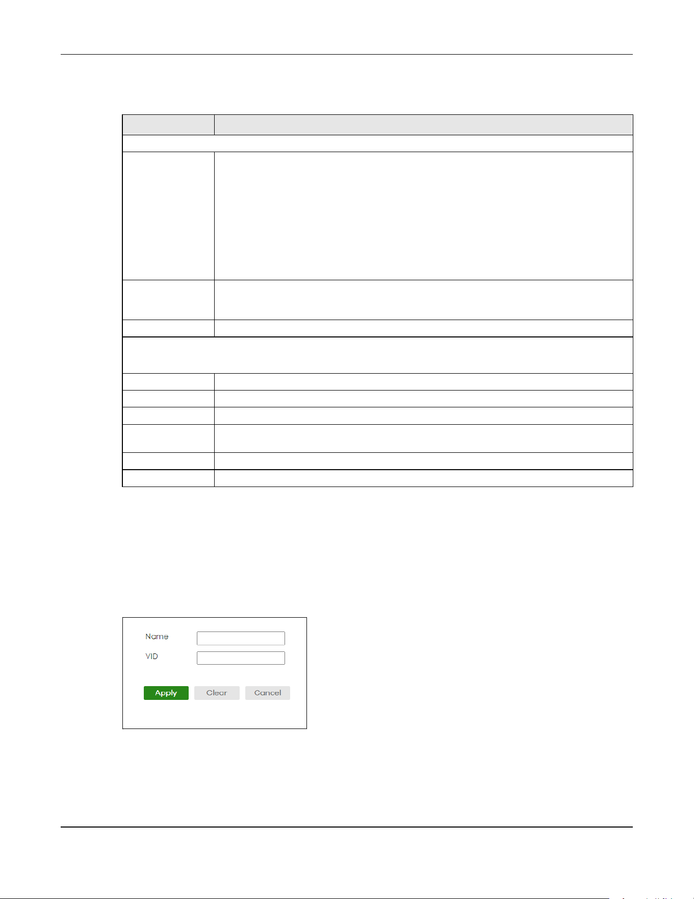
Chapter 80 Networked AV Mode
XGS2220 Series User’s Guide
667
The following table describes the labels in this screen.
80.30.1 Add/Edit IGMP Snooping VLANs
This screen allows you to add an IGMP snooping VLAN or edit an existing one.
To access this screen, click the Add/Edit button or select an entry from the list and click the Add/Edit
button.
Figure 534 SWITCHING > Multicast > IGMP Snooping VLAN > Add/Edit
Table 350 SWITCHING > Multicast > IGMP Snooping VLAN
LABEL DESCRIPTION
IGMP Snooping VLAN
Mode Select auto to have the Switch learn multicast group membership information of any VLANs
automatically.
Select fixed to have the Switch only learn multicast group membership information of the
VLANs that you specify below.
In either auto or fixed mode, the Switch can learn up to 16 VLANs.
The Switch drops any IGMP control messages which do not belong to these 16 VLANs.
You must also enable IGMP snooping in the SWITCHING > Multicast > IGMP Snooping screen
first.
Apply Click Apply to save your changes to the Switch’s run-time memory. The Switch loses these
changes if it is turned off or loses power, so use the Save link on the top navigation panel to
save your changes to the non-volatile memory when you are done configuring.
Cancel Click Cancel to begin configuring this screen afresh.
VLAN
Use this section of the screen to add VLANs on which the Switch is to perform IGMP snooping.
Index This is the index number of the IGMP snooping VLAN entry in the table.
Name This field displays the descriptive name for this VLAN group.
VID This field displays the ID number of the VLAN group.
Select an entry’s check box to select a specific entry. Otherwise, select the check box in the
table heading row to select all entries.
Add/Edit Click Add/Edit to create a new entry or edit a selected one.
Delete Click Delete to remove the selected entries.

Chapter 80 Networked AV Mode
XGS2220 Series User’s Guide
668
The following table describes the labels in this screen.
80.31 IGMP Filtering Profile
An IGMP filtering profile specifies a range of multicast groups that clients connected to the Switch are
able to join. A profile contains a range of multicast IP addresses which you want clients to be able to
join. Profiles are assigned to ports (in the SWITCHING > Multicast > IGMP Snooping screen). Clients
connected to those ports are then able to join the multicast groups specified in the profile. Each port
can be assigned a single profile. A profile can be assigned to multiple ports.
Click SWITCHING > Multicast > IGMP Filtering Profile link to display the screen as shown.
Figure 535 SWITCHING > Multicast > IGMP Filtering Profile
The following table describes the labels in this screen.
Table 351 SWITCHING > Multicast > IGMP Snooping VLAN > Add/Edit
LABEL DESCRIPTION
Name Enter the descriptive name (up to 32 printable ASCII characters except [ ? ], [ | ], [ ' ], [ " ] or [ ,
])of the VLAN for identification purposes.
VID Enter the ID of a static VLAN; the valid range is between 1 and 4094.
Apply Click Apply to save your changes to the Switch’s run-time memory. The Switch loses these
changes if it is turned off or loses power, so use the Save link on the top navigation panel to
save your changes to the non-volatile memory when you are done configuring.
Clear Click Clear to clear the fields to the factory defaults.
Cancel Click Cancel to not save the configuration you make and return to the last screen.
Table 352 SWITCHING > Multicast > IGMP Filtering Profile
LABEL DESCRIPTION
Profile Name This field displays the descriptive name of the profile.
Start Address This field displays the start of the multicast address range.
End Address This field displays the end of the multicast address range.
Select an entry’s check box to select a specific entry. Otherwise, select the check box in the
table heading row to select all entries.
Add Profile Click this to add a new IGMP filtering profile.
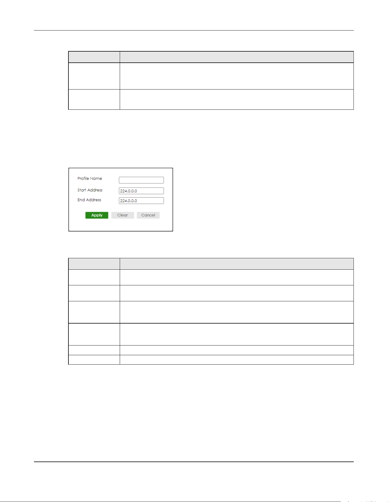
Chapter 80 Networked AV Mode
XGS2220 Series User’s Guide
669
80.31.1 Add IGMP Filtering Profile
To access this screen, click the Add Profile button in the SWITCHING > Multicast > IGMP Filtering Profile
screen.
Figure 536 SWITCHING > Multicast > IGMP Filtering Profile > Add Profile
The following table describes the labels in this screen.
80.31.2 Add IGMP Filtering Rule
Click Add Rule in the SWITCHING > Multicast > IGMP Filtering Profile screen to access this screen.
Add Rule Click Add Rule to add a new rule and specify the profile it belongs to in the Add Rule screen.
You can also select a profile entry and click Add Rule to add an additional rule for the
selected profile.
Delete Select a profile and click Delete to remove the selected profile and the accompanying rules.
Select a rule from a profile and click Delete to remove the selected rule.
Table 352 SWITCHING > Multicast > IGMP Filtering Profile (continued)
LABEL DESCRIPTION
Table 353 SWITCHING > Multicast > IGMP Filtering Profile > Add Profile
LABEL DESCRIPTION
Profile Name Enter a descriptive name for the profile for identification purposes. You can enter up to 32
printable ASCII characters except [ ? ], [ | ], [ ' ], [ " ] or [ , ].
Start Address Enter the starting multicast IP address for a range of multicast IP addresses that you want to
belong to the IGMP filter profile.
End Address Enter the ending multicast IP address for a range of IP addresses that you want to belong to
the IGMP filter profile. If you want to add a single multicast IP address, enter it in both the Start
Address and End Address fields.
Apply Click Apply to save your changes to the Switch’s run-time memory. The Switch loses these
changes if it is turned off or loses power, so use the Save link on the top navigation panel to
save your changes to the non-volatile memory when you are done configuring.
Clear Click Clear to clear the fields to the factory defaults.
Cancel Click Cancel to not save the configuration you make and return to the last screen.

Chapter 80 Networked AV Mode
XGS2220 Series User’s Guide
670
Figure 537 SWITCHING > Multicast > IGMP Filtering Profile > Add Rule
The following table describes the labels in this screen.
80.32 VLAN
This section shows you how to configure 802.1Q tagged and port-based VLANs.
80.32.1 What You Can Do
• Use the VLAN Status screen (Section 80.33 on page 673) to view and search all static VLAN groups.
• Use the VLAN Detail screen (Section 80.33.1 on page 674) to view detailed port settings and status of
the static VLAN group.
• Use the Static VLAN screen (Section 80.34 on page 675) to configure a static VLAN for the Switch.
• Use the VLAN Port Setup screen (Section 80.35 on page 677) to configure the static VLAN (IEEE 802.1Q)
settings on a port.
80.32.2 What You Need to Know
Read this section to know more about VLAN and how to configure the screens.
Table 354 SWITCHING > Multicast > IGMP Filtering Profile > Add Rule
LABEL DESCRIPTION
Profile Name Select a profile from the drop-down list to add a additional rule for the existing profile.
Start Address Enter the starting multicast IP address for a range of multicast IP addresses that you want to
belong to the IGMP filter profile.
End Address Enter the ending multicast IP address for a range of IP addresses that you want to belong to
the IGMP filter profile. If you want to add a single multicast IP address, enter it in both the Start
Address and End Address fields.
Apply Click Apply to save your changes to the Switch’s run-time memory. The Switch loses these
changes if it is turned off or loses power, so use the Save link on the top navigation panel to
save your changes to the non-volatile memory when you are done configuring.
Clear Click Clear to clear the fields to the factory defaults.
Cancel Click Cancel to not save the configuration you make and return to the last screen.
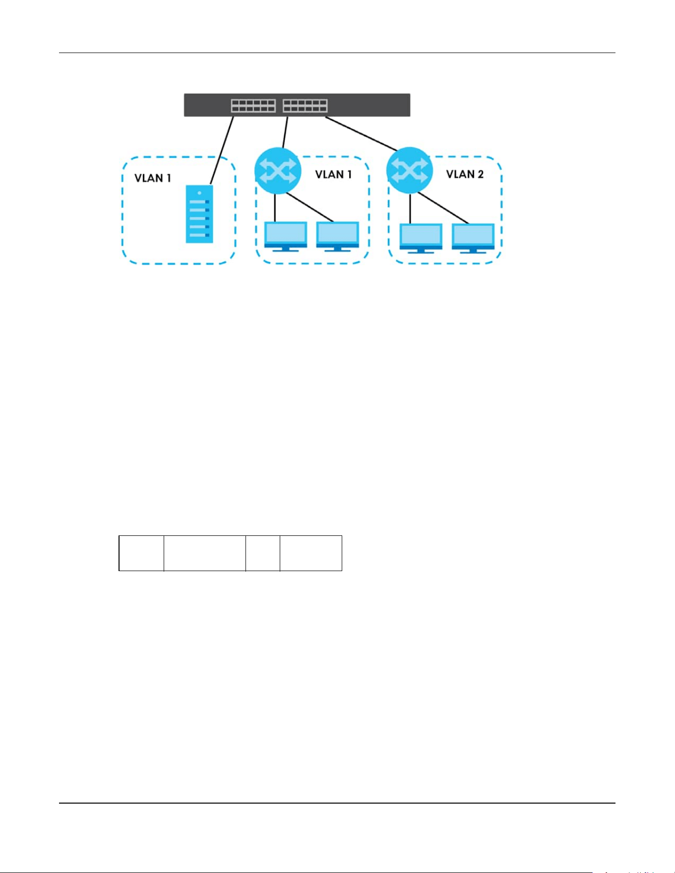
Chapter 80 Networked AV Mode
XGS2220 Series User’s Guide
671
Figure 538 Shared Server Using VLAN Example
IEEE 802.1Q Tagged VLANs
A tagged VLAN uses an explicit tag (VLAN ID) in the MAC header to identify the VLAN membership of a
frame across bridges
– they are not confined to the switch on which they were created. The VLANs can
be created statically by hand dynamically through GVRP. The VLAN ID associates a frame with a
specific VLAN and provides the information that switches need to process the frame across the network.
A tagged frame is 4 bytes longer than an untagged frame and contains 2 bytes of TPID (Tag Protocol
Identifier, residing within the type or length field of the Ethernet frame) and 2 bytes of TCI (Tag Control
Information, starts after the source address field of the Ethernet frame).
The CFI (Canonical Format Indicator) is a single-bit flag, always set to zero for Ethernet switches. If a
frame received at an Ethernet port has a CFI set to 1, then that frame should not be forwarded as it is to
an untagged port. The remaining twelve bits define the VLAN ID, giving a possible maximum number of
4,096 VLANs. Note that user priority and VLAN ID are independent of each other. A frame with VID
(VLAN Identifier) of null (0) is called a priority frame, meaning that only the priority level is significant and
the default VID of the ingress port is given as the VID of the frame. Of the 4,096 possible VIDs, a VID of 0 is
used to identify priority frames and value 4095 (FFF) is reserved, so the maximum possible VLAN
configurations are 4,094.
Forwarding Tagged and Untagged Frames
Each port on the Switch is capable of passing tagged or untagged frames. To forward a frame from an
802.1Q VLAN-aware switch to an 802.1Q VLAN-unaware switch, the Switch first decides where to
forward the frame and then strips off the VLAN tag. To forward a frame from an 802.1Q VLAN-unaware
switch to an 802.1Q VLAN-aware switch, the Switch first decides where to forward the frame, and then
inserts a VLAN tag reflecting the ingress port's default VID. The default PVID is VLAN 1 for all ports, but this
can be changed.
TPID
2 Bytes
User Priority
3 Bits
CFI
1 Bit
VLAN ID
12 bits

Chapter 80 Networked AV Mode
XGS2220 Series User’s Guide
672
Figure 539 VLAN Forwarding Frame
A broadcast frame (or a multicast frame for a multicast group that is known by the system) is duplicated
only on ports that are members of the VID (except the ingress port itself), thus confining the broadcast to
a specific domain.
80.32.2.1 Automatic VLAN Registration
GARP and GVRP are the protocols used to automatically register VLAN membership across switches.
GARP
GARP (Generic Attribute Registration Protocol) allows network switches to register and de-register
attribute values with other GARP participants within a bridged LAN. GARP is a protocol that provides a
generic mechanism for protocols that serve a more specific application, for example, GVRP.
GARP Timers
Switches join VLANs by making a declaration. A declaration is made by issuing a Join message using
GARP. Declarations are withdrawn by issuing a Leave message. A Leave All message terminates all
registrations. GARP timers set declaration timeout values.
GVRP
GVRP (GARP VLAN Registration Protocol) is a registration protocol that defines a way for switches to
register necessary VLAN members on ports across the network. Enable this function to permit VLAN
groups beyond the local Switch.
Please refer to the following table for common IEEE 802.1Q VLAN terminology.
Table 355 IEEE 802.1Q VLAN Terminology
VLAN PARAMETER TERM DESCRIPTION
VLAN Type Permanent VLAN This is a static VLAN created manually.
Dynamic VLAN This is a VLAN configured by a GVRP registration or de-registration
process.
VLAN Administrative
Control
Registration Fixed Fixed registration ports are permanent VLAN members.
Registration
Forbidden
Ports with registration forbidden are forbidden to join the specified
VLAN.
Normal Registration Ports dynamically join a VLAN using GVRP.
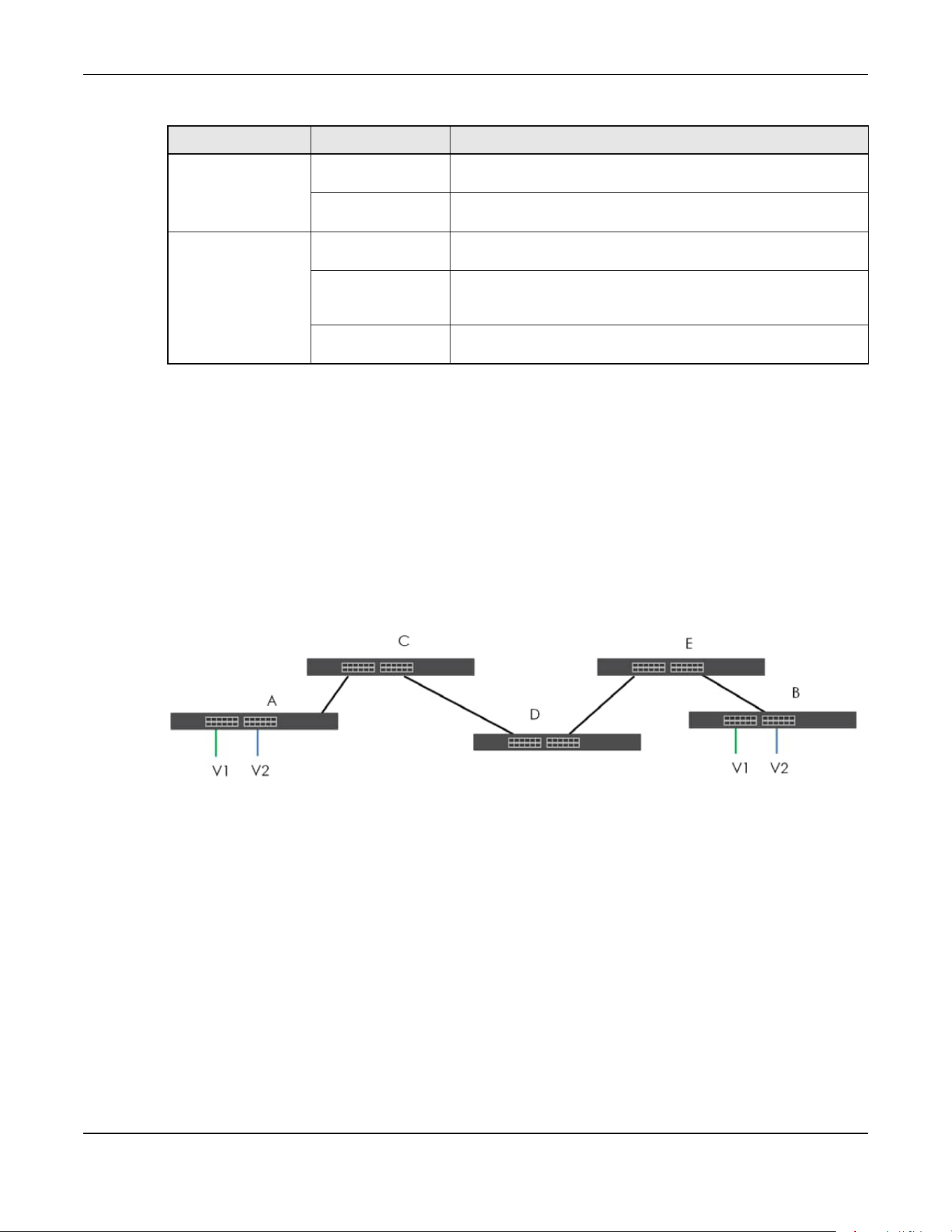
Chapter 80 Networked AV Mode
XGS2220 Series User’s Guide
673
80.32.2.2 Port VLAN Trunking
Enable VLAN Trunking on a port to allow frames belonging to unknown VLAN groups to pass through
that port. This is useful if you want to set up VLAN groups on end devices without having to configure the
same VLAN groups on intermediary devices.
Refer to the following figure. Suppose you want to create VLAN groups 1 and 2 (V1 and V2) on devices
A and B. Without VLAN Trunking, you must configure VLAN groups 1 and 2 on all intermediary switches C,
D and E; otherwise they will drop frames with unknown VLAN group tags. However, with VLAN Trunking
enabled on ports in each intermediary switch you only need to create VLAN groups in the end devices
(A and B). C, D and E automatically allow frames with VLAN group tags 1 and 2 (VLAN groups that are
unknown to those switches) to pass through their VLAN trunking ports.
Figure 540 Port VLAN Trunking
80.33 VLAN Status
Use this screen to view and search all static VLAN groups. Click SWITCHING > VLAN > VLAN Status from
the navigation panel to display the screen as shown next.
VLAN Tag Control Tagged Ports belonging to the specified VLAN tag all outgoing frames
transmitted.
Untagged Ports belonging to the specified VLAN do not tag all outgoing
frames transmitted.
VLAN Port Port VID This is the VLAN ID assigned to untagged frames that this port
received.
Acceptable Frame
Type
You may choose to accept both tagged and untagged incoming
frames, just tagged incoming frames or just untagged incoming
frames on a port.
Ingress filtering If set, the Switch discards incoming frames for VLANs that do not
have this port as a member.
Table 355 IEEE 802.1Q VLAN Terminology (continued)
VLAN PARAMETER TERM DESCRIPTION

Chapter 80 Networked AV Mode
XGS2220 Series User’s Guide
674
Figure 541 SWITCHING > VLAN > VLAN Status
The following table describes the labels in this screen.
80.33.1 VLAN Details
Use this screen to view detailed port settings and status of the static VLAN group. Click an index number
in the VLAN Status screen to display VLAN details.
Table 356 SWITCHING > VLAN > VLAN Status
LABEL DESCRIPTION
VLAN Search by
VID
Enter (an) existing VLAN ID numbers (use a comma (,) to separate individual VLANs or a hyphen
(-) to indicate a range of VLANs. For example, “3,4” or “3-9”) and click Search to display only the
specified VLANs in the list below.
Leave this field blank and click Search to display all VLANs configured on the Switch.
The Number of
VLAN
This is the number of VLANs configured on the Switch.
The Number of
Search Results
This is the number of VLANs that match the searching criteria and display in the list below.
This field displays only when you use the Search button to look for certain VLANs.
Index This is the VLAN index number. Click an index number to view more VLAN details.
VID This is the VLAN identification number that was configured in the corresponding VLAN
configuration screen.
Name This fields shows the descriptive name of the VLAN.
Tagged Port This field shows the tagged ports that are participating in the VLAN.
Untagged Port This field shows the untagged ports that are participating in the VLAN.
Elapsed Time This field shows how long it has been since a normal VLAN was registered or a static VLAN was
set up.
Status This field shows how this VLAN was added to the Switch.
• Dynamic – using GVRP
• Static – added as a permanent VLAN
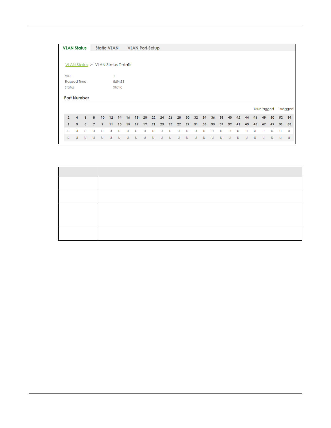
Chapter 80 Networked AV Mode
XGS2220 Series User’s Guide
675
Figure 542 SWITCHING > VLAN > VLAN Status > VLAN Status Details
The following table describes the labels in this screen.
80.34 Configure a Static VLAN
Use a static VLAN to decide whether an incoming frame on a port should be
• sent to a VLAN group as normal depending on its VLAN tag.
• sent to a group whether it has a VLAN tag or not.
• blocked from a VLAN group regardless of its VLAN tag.
You can also tag all outgoing frames (that were previously untagged) from a port with the specified
VID.
Use this screen to view and configure a static VLAN for the Switch. Click SWITCHING > VLAN > Static
VLAN to display the screen as shown next.
Table 357 SWITCHING > VLAN > VLAN Status > VLAN Status Details
LABEL DESCRIPTION
VID This is the VLAN identification number that was configured in the corresponding VLAN
configuration screen.
Elapsed Time This field shows how long it has been since a normal VLAN was registered or a static VLAN was
set up.
Status This field shows how this VLAN was added to the Switch.
• Dynamic: using GVRP
• Static: added as a permanent entry
Port Number This section displays the ports that are participating in a VLAN. A tagged port is marked as T, an
untagged port is marked as U and ports not participating in a VLAN are marked as “–“.

Chapter 80 Networked AV Mode
XGS2220 Series User’s Guide
676
Figure 543 SWITCHING > VLAN > Static VLAN
The following table describes the related labels in this screen.
80.34.1 Add/Edit a Static VLAN
Use this screen to configure a static VLAN for the Switch. Click Add/Edit, or select an entry and click
Add/Edit in the SWITCHING > VLAN > Static VLAN screen to display this screen.
Figure 544 SWITCHING > VLAN > Static VLAN > Add/Edit
Table 358 SWITCHING > VLAN > Static VLAN
LABEL DESCRIPTION
VID This field displays the ID number of the VLAN group.
Active This field indicates whether the VLAN settings are enabled or disabled.
Name This field displays the descriptive name for this VLAN group.
Select an entry’s check box to select a specific entry. Otherwise, select the check box in the
table heading row to select all entries.
Add/Edit Click Add/Edit to add a new static VLAN or edit a selected one.
Delete Click Delete to remove the selected static VLAN.

Chapter 80 Networked AV Mode
XGS2220 Series User’s Guide
677
The following table describes the related labels in this screen.
80.35 VLAN Port Setup
Use this screen to configure the static VLAN (IEEE 802.1Q) settings on a port. Click SWITCHING > VLAN >
VLAN Port Setup to display the screen as shown.
Figure 545 SWITCHING > VLAN > VLAN Port Setup
Table 359 SWITCHING > VLAN > Static VLAN > Add/Edit
LABEL DESCRIPTION
Active Enable the switch button to activate the VLAN settings.
Name Enter a descriptive name for the VLAN group for identification purposes. This name consists of up
to 64 printable ASCII characters. The string should not contain [ ? ], [ | ], [ ' ], [ " ] or [ , ].
VLAN Group ID Enter the VLAN ID for this static entry; the valid range is between 1 and 4094.
Port The port number identifies the port you are configuring.
* Settings in this row apply to all ports.
Use this row only if you want to make some settings the same for all ports. Use this row first to set
the common settings and then make adjustments on a port-by-port basis.
Note: Changes in this row are copied to all the ports as soon as you make them.
Control Select Normal for the port to dynamically join this VLAN group using GVRP. This is the default
selection.
Select Fixed for the port to be a permanent member of this VLAN group.
Select Forbidden if you want to prohibit the port from joining this VLAN group.
Tagging Select Tx Tagging if you want the port to tag all outgoing frames transmitted with this VLAN
Group ID.
Apply Click Apply to save your changes to the Switch’s run-time memory. The Switch loses these
changes if it is turned off or loses power, so use the Save link on the top navigation panel to save
your changes to the non-volatile memory when you are done configuring.
Clear Click Clear to clear the fields to the factory defaults.
Cancel Click Cancel to not save the configuration you make and return to the last screen.

Chapter 80 Networked AV Mode
XGS2220 Series User’s Guide
678
The following table describes the labels in this screen.
80.36 SECURITY
The following sections introduce the SECURITY screens.
80.37 Access Control
A console port and FTP are allowed one session each, Telnet and SSH share nine sessions, up to five Web
sessions (five different user names and passwords) and/or limitless SNMP access control sessions are
allowed.
Table 360 SWITCHING > VLAN > VLAN Port Setup
LABEL DESCRIPTION
Port This field displays the port number.
* Settings in this row apply to all ports.
Use this row only if you want to make some settings the same for all ports. Use this row first to set
the common settings and then make adjustments on a port-by-port basis.
Note: Changes in this row are copied to all the ports as soon as you make them.
Ingress Check If this check box is selected, the Switch discards incoming frames on a port for VLANs that do
not include this port in its member set.
Clear this check box to disable ingress filtering.
PVID A PVID (Port VLAN ID) is a tag that adds to incoming untagged frames received on a port so
that the frames are forwarded to the VLAN group that the tag defines.
Enter a number between 1and 4094 as the port VLAN ID.
Acceptable
Frame Type
Specify the type of frames allowed on a port. Choices are All, Tag Only and Untag Only.
Select All from the drop-down list box to accept all untagged or tagged frames on this port.
This is the default setting.
Select Tag Only to accept only tagged frames on this port. All untagged frames will be
dropped.
Select Untag Only to accept only untagged frames on this port. All tagged frames will be
dropped.
VLAN Trunking Enable VLAN Trunking on ports connected to other switches or routers (but not ports directly
connected to end users) to allow frames belonging to unknown VLAN groups to pass through
the Switch.
Isolation Select this to allows this port to communicate only with the CPU management port and the
ports on which the isolation feature is NOT enabled.
Apply Click Apply to save your changes to the Switch’s run-time memory. The Switch loses these
changes if it is turned off or loses power, so use the Save link on the top navigation panel to
save your changes to the non-volatile memory when you are done configuring.
Cancel Click Cancel to begin configuring this screen afresh.
Table 361 Access Control Overview
Console Port SSH Telnet FTP Web SNMP
One session Share up to 9 sessions One session Up to 5 accounts No limit
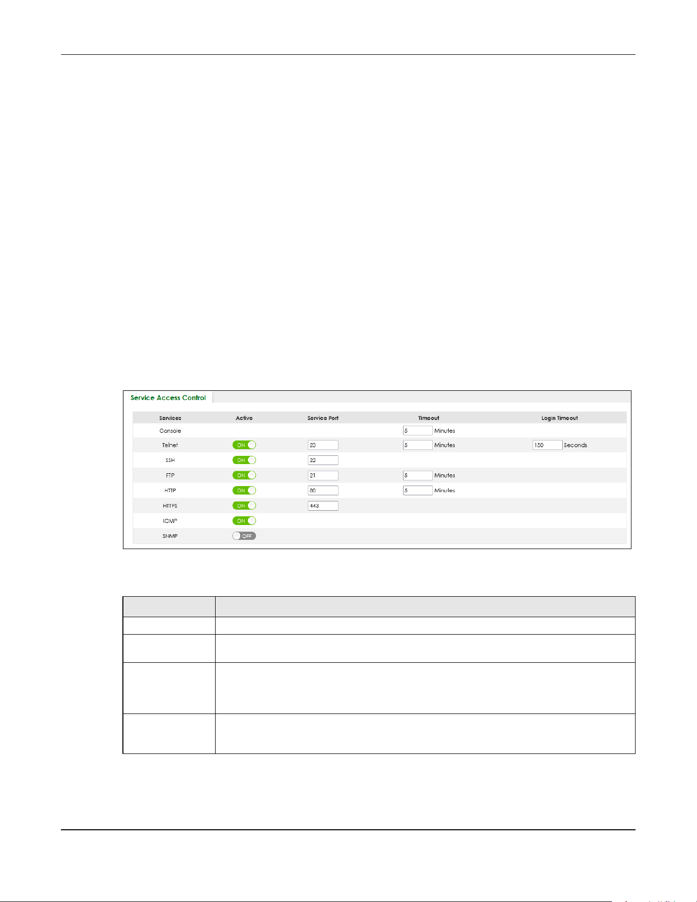
Chapter 80 Networked AV Mode
XGS2220 Series User’s Guide
679
A console port access control session and Telnet access control session cannot coexist when multi-login
is disabled. See the CLI Reference Guide for more information on disabling multi-login.
This section describes how to control access to the Switch.
80.37.1 What You Can Do
• Use the Service Access Control screen (Section 80.38 on page 679) to decide what services you may
use to access the Switch.
• Use the Remote Management screen (Section 80.39 on page 680) to specify a group of one or more
“trusted computers” from which an administrator may use a service to manage the Switch.
80.38 Service Access Control
Service Access Control allows you to decide what services you may use to access the Switch. You may
also change the default service port and configure “trusted computers” for each service in the Remote
Management screen (discussed earlier). Click SECURITY > Access Control > Service Access Control to
view the screen as shown.
Figure 546 SECURITY > Access Control > Service Access Control
The following table describes the fields in this screen.
Table 362 SECURITY > Access Control > Service Access Control
LABEL DESCRIPTION
Services Services you may use to access the Switch are listed here.
Active Enable the switch button for the corresponding services that you want to allow to access the
Switch.
Service Port For Telnet, SSH, FTP, HTTP or HTTPS services, you may change the default service port by typing
the new port number in the Service Port field. If you change the default port number then you
will have to let people (who wish to use the service) know the new port number for that
service.
Timeout Enter how many minutes (from 1 to 255) a management session can be left idle before the
session times out. After it times out you have to log in with your password again. Very long idle
timeouts may have security risks.

Chapter 80 Networked AV Mode
XGS2220 Series User’s Guide
680
80.39 Remote Management
Use this screen to specify a group of one or more “trusted computers” from which an administrator may
use a service to manage the Switch.
Click SECURITY > Access Control > Remote Management to view the screen as shown next.
Figure 547 SECURITY > Access Control > Remote Management
The following table describes the labels in this screen.
Login Timeout The Telnet or SSH server do not allow multiple user logins at the same time. Enter how many
seconds (from 30 to 300 seconds) a login session times out. After it times out you have to start
the login session again. Very long login session timeouts may have security risks.
For example, if User A attempts to connect to the Switch (through SSH), but during the login
stage, do not enter the user name and/or password, User B cannot connect to the Switch
(through SSH) before the Login Timeout for User A expires (default 150 seconds).
Apply Click Apply to save your changes to the Switch’s run-time memory. The Switch loses these
changes if it is turned off or loses power, so use the Save link on the top navigation panel to
save your changes to the non-volatile memory when you are done configuring.
Cancel Click Cancel to begin configuring this screen afresh.
Table 362 SECURITY > Access Control > Service Access Control (continued)
LABEL DESCRIPTION
Table 363 SECURITY > Access Control > Remote Management
LABEL DESCRIPTION
Entry This is the client set index number. A “client set” is a group of one or more “trusted computers”
from which an administrator may use a service to manage the Switch.
Active Enable the switch button to activate this secured client set. Clear the check box if you wish to
temporarily disable the set without deleting it.

Chapter 80 Networked AV Mode
XGS2220 Series User’s Guide
681
80.40 Storm Control
Storm control limits the number of broadcast, multicast and destination lookup failure (DLF) packets the
Switch receives per second on the ports. When the maximum number of allowable broadcast, multicast
and/or DLF packets is reached per second, the subsequent packets are discarded. Enable this feature
to reduce broadcast, multicast and/or DLF packets in your network. You can specify limits for each
packet type on each port.
Click SECURITY > Storm Control in the navigation panel to display the screen as shown next.
Figure 548 SECURITY > Storm Control
Start Address
End Address
Configure the IP address range of trusted computers from which you can manage this Switch.
The Switch checks if the client IP address of a computer requesting a service or protocol matches
the range set here. The Switch immediately disconnects the session if it does not match.
Telnet / FTP /
HTTP / ICMP /
SNMP / SSH /
HTTPS
Select services that may be used for managing the Switch from the specified trusted computers.
Apply Click Apply to save your changes to the Switch’s run-time memory. The Switch loses these
changes if it is turned off or loses power, so use the Save link on the top navigation panel to save
your changes to the non-volatile memory when you are done configuring.
Cancel Click Cancel to begin configuring this screen afresh.
Table 363 SECURITY > Access Control > Remote Management (continued)
LABEL DESCRIPTION

Chapter 80 Networked AV Mode
XGS2220 Series User’s Guide
682
The following table describes the labels in this screen.
80.41 MAINTENANCE
This section explains how to configure the screens that let you maintain the firmware and configuration
files.
80.42 What You Can Do
• Use the Restore Configuration screen (Section 80.43 on page 682) to upload a stored device
configuration file.
• Use the Backup Configuration screen (Section 80.44 on page 683) to save your configuration for later
use.
• Use the Save Configuration screen (Section 80.45 on page 684) to save the current configuration
settings to a specific configuration file on the Switch.
• Use the Firmware Upgrade screen (Section 80.46 on page 684) to upload the latest firmware.
• Use the Reboot System screen (Section 80.47 on page 685) to restart the Switch without physically
turning the power off and load a specific configuration file.
• Use the Tech-Support screen (Section 80.48 on page 686) to create reports for customer support if
there are problems with the Switch.
80.43 Restore Configuration
Use this screen to restore a previously saved configuration file from your computer to the Switch.
Table 364 SECURITY > Storm Control
LABEL DESCRIPTION
Active Enable the switch button to enable traffic storm control on the Switch. Disable the switch
button to disable this feature.
Port This field displays the port number.
* Settings in this row apply to all ports.
Use this row only if you want to make some settings the same for all ports. Use this row first to set
the common settings and then make adjustments on a port-by-port basis.
Note: Changes in this row are copied to all the ports as soon as you make them.
Broadcast (pkt/s) Select this option and specify how many broadcast packets the port receives per second.
Multicast (pkt/s) Select this option and specify how many multicast packets the port receives per second.
DLF (pkt/s) Select this option and specify how many destination lookup failure (DLF) packets the port
receives per second.
Apply Click Apply to save your changes to the Switch’s run-time memory. The Switch loses these
changes if it is turned off or loses power, so use the Save link on the top navigation panel to
save your changes to the non-volatile memory when you are done configuring.
Cancel Click Cancel to reset the fields.

Chapter 80 Networked AV Mode
XGS2220 Series User’s Guide
683
Click MAINTENANCE > Configuration > Restore Configuration to access this screen.
Figure 549 MAINTENANCE > Configuration > Restore Configuration
1 Click Choose File or Browse to locate the configuration file you wish to restore.
2 After you have specified the file, click Restore.
The Switch will run on the restored configuration after the restore process.
Figure 550 Configuration Restoring
80.44 Backup Configuration
Backing up your Switch configurations allows you to create various “snap shots” of your device from
which you may restore at a later date. Use this screen to back up your current Switch configuration to a
computer.
To access this screen, click MAINTENANCE > Configuration > Backup Configuration in the navigation
panel.
Figure 551 MAINTENANCE > Configuration > Backup Configuration
Follow the steps below to back up the current Switch configuration to your computer in this screen.
1 Select which Switch configuration file you want to download to your computer.
2 Click Backup.
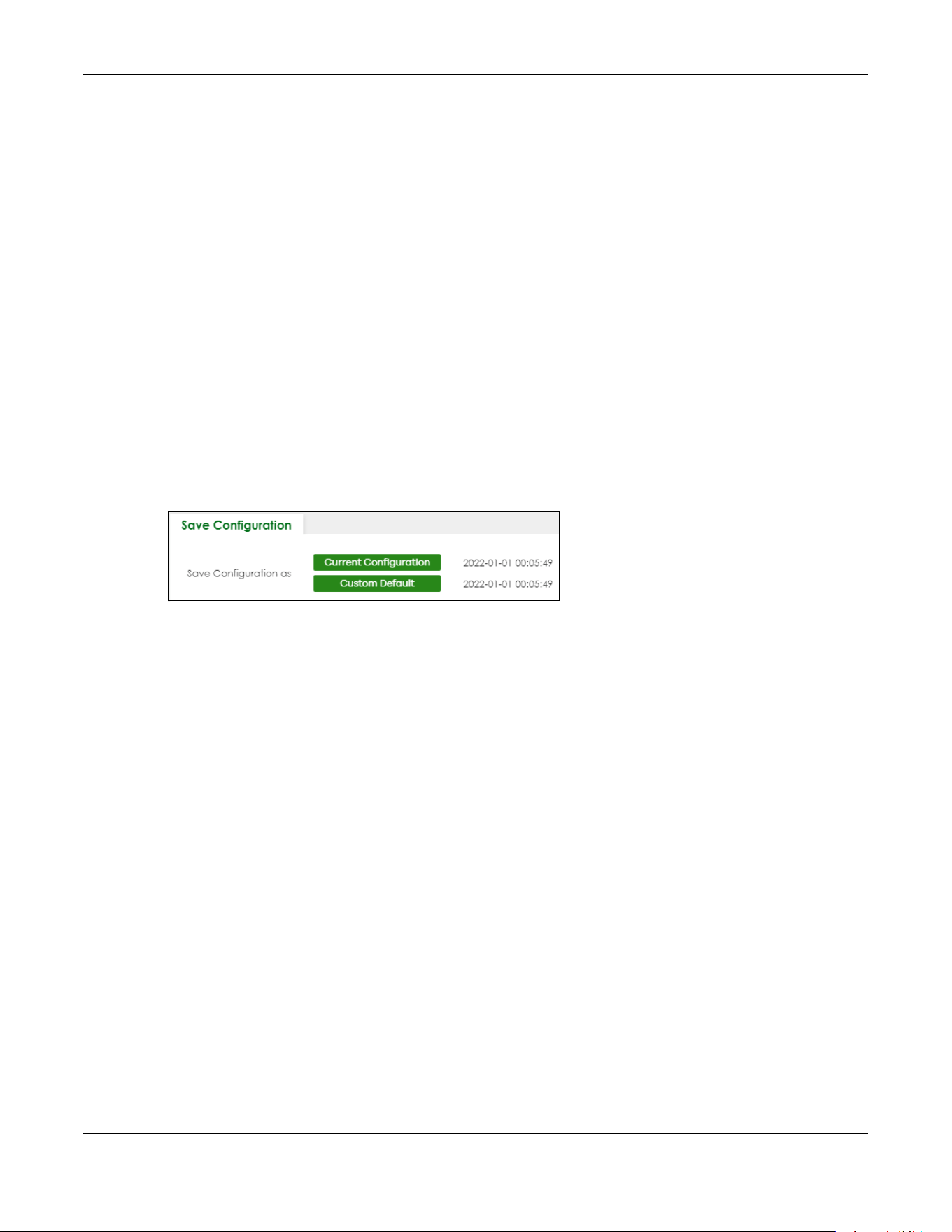
Chapter 80 Networked AV Mode
XGS2220 Series User’s Guide
684
3 If the current configuration file is open and/or downloaded to your computer automatically, you can
click File > Save As on your computer to save the file to a specific place.
If a dialog box pops up asking whether you want to open or save the file, click Save or Save File to
download it to the default downloads folder on your computer. If a Save As screen displays after you
click Save or Save File, choose a location to save the file on your computer from the Save in drop-down
list box and type a descriptive name for it in the File name list box. Click Save to save the configuration
file to your computer.
80.45 Save Configuration
To access this screen, click MAINTENANCE > Configuration > Save Configuration in the navigation panel.
Click Current Configuration to save the current configuration settings permanently to the Switch. This
configuration is set up according to your network environment.
Click Custom Default to save the current configuration settings permanently to a customized default file
on the Switch.
Figure 552 Maintenance > Configuration > Save Configuration
Note: If a customized default file was not saved, clicking Custom Default loads the factory
default configuration on the Switch.
Alternatively, click Save on the top right in any screen to save the configuration changes to the current
configuration.
Note: Clicking the Apply button after making configuration does NOT save the changes
permanently. All unsaved changes are erased after you reboot the Switch.
80.46 Firmware Upgrade
Use the following screen to upgrade your Switch to the latest firmware.
Note: Make sure you have downloaded (and unzipped) the correct model firmware and
version to your computer before uploading to the device.
Click MAINTENANCE > Firmware Upgrade to view the screen as shown next.

Chapter 80 Networked AV Mode
XGS2220 Series User’s Guide
685
Figure 553 MAINTENANCE > Firmware Upgrade
Click Choose File or Browse to locate the firmware file you wish to upload to the Switch. Firmware
upgrades are only applied after a reboot. Click Upgrade to load the new firmware.
After the firmware upgrade process is complete, see the MONITOR > System Information screen to verify
your current firmware version number.
80.47 Reboot System
Reboot System allows you to restart the Switch without physically turning the power off. It also allows you
to load the Current Configuration, a Custom Default or the Factory Default configuration when you
reboot. Follow the steps below to reboot the Switch.
Click MAINTENANCE > Reboot System to view the screen as shown next.
Figure 554 MAINTENANCE > Reboot System
1 Click the Current Configuration, Factory Default, or Custom Default button to reboot and load that
configuration file. The confirmation screen displays.
Table 365 MAINTENANCE > Firmware Upgrade
LABEL DESCRIPTION
Name This is the name of the Switch that you are configuring.
Version This is the version number (and model code) and MM/DD/YYYY creation date of the
firmware currently in use on the Switch. The firmware information is also displayed in
MONITOR > SYSTEM Information.
File Path Click Choose File or Browse to locate the firmware file you wish to upload to the Switch.
Upgrade Click Upgrade to load the new firmware. Firmware upgrades are only applied after a
reboot. To reboot, go to MAINTENANCE > Reboot System and click Current Configuration,
Factory Default, or Custom Default (Current Configuration, Factory Default, and Custom
Default are the configuration files you want the Switch to use when it restarts).
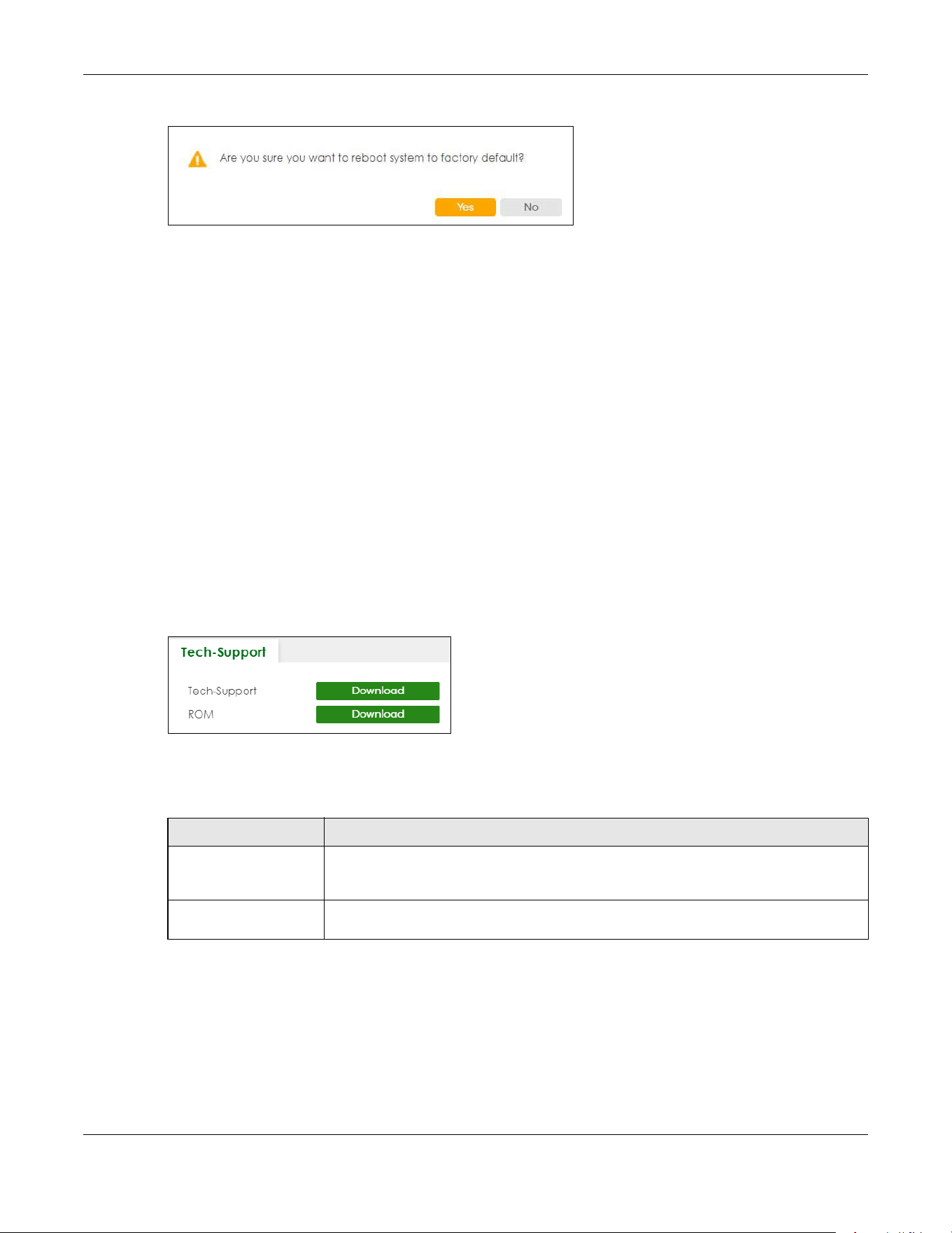
Chapter 80 Networked AV Mode
XGS2220 Series User’s Guide
686
Figure 555 Reboot Confirmation Example: Factory Default
2 Click YES and then wait for the Switch to restart. This takes up to 2 minutes.
Click Current Configuration and follow steps 1 to 2 to reboot and load configuration one on the Switch.
Click Factory Default and follow steps 1 to 2 to reboot and load Zyxel factory default configuration
settings on the Switch.
Click Custom Default and follow steps 1 to 2 to reboot and load a customized default file on the Switch.
80.48 Tech-Support
The Tech-Support feature is a log enhancement tool that logs useful information such as CPU utilization
history, memory and Mbuf (Memory Buffer) log and crash reports for issue analysis by customer support
should you have difficulty with your Switch. The Tech Support menu eases your effort in obtaining reports
and it is also available in CLI command by typing “Show tech-support” command.
Click MAINTENANCE > Tech-Support to see the following screen.
Figure 556 MAINTENANCE > Tech-Support
You may need WordPad or similar software to see the log report correctly. The table below describes
the fields in the above screen.
80.48.1 Tech-Support Download
When you click Download to save your current Switch configuration to a computer, the following screen
appears. When the log report has downloaded successfully, click Back to return to the previous screen.
Table 366 MAINTENANCE > Tech-Support
LABEL DESCRIPTION
Tech-Support Click Download to see all the log report and system status. This log report is stored in flash
memory. If the All log report is too large, you can download the log reports separately
below.
ROM Click Download to see the Read Only Memory (ROM) log report. This report is stored in
flash memory.
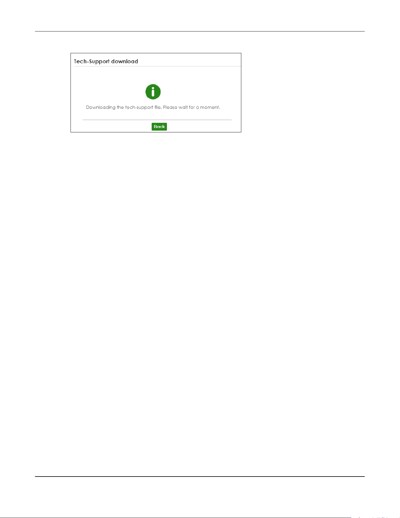
Chapter 80 Networked AV Mode
XGS2220 Series User’s Guide
687
Figure 557 MAINTENANCE > Tech-Support: Download

688
PART III
Troubleshooting and
Appendices

XGS2220 Series User’s Guide
689
CHAPTER 81
Troubleshooting
This chapter offers some suggestions to solve problems you might encounter. The potential problems are
divided into the following categories.
• Power, Hardware Connections, and LEDs
• Switch Access and Login
• Switch Configuration
• PoE Supply
• Nebula Registration
81.1 Power, Hardware Connections, and LEDs
The Switch does not turn on. None of the LEDs turn on.
1 Make sure you are using the power adapter or cord included with the Switch.
2 Make sure the power adapter or cord is connected to the Switch and plugged in to an appropriate
power source. Make sure the power source is turned on.
3 Disconnect and re-connect the power adapter or cord to the Switch.
4 If the problem continues, contact the vendor.
One of the LEDs does not behave as expected.
1 Make sure you understand the normal behavior of the LED. See Section 3.3 on page 54.
2 Check the hardware connections. See Section 3.1 on page 45.
3 Inspect your cables for damage. Contact the vendor to replace any damaged cables.
4 Disconnect and re-connect the power adapter or cord to the Switch.
5 If the problem continues, contact the vendor.

Chapter 81 Troubleshooting
XGS2220 Series User’s Guide
690
81.2 Switch Access and Login
I can see the Login screen, but I cannot log in to the Switch. (I forgot the user name and/or
password.)
1 Check the Switch’s management mode by using the CLOUD LED. See Section 3.3 on page 54 for more
information on the LED descriptions.
• If you are in Cloud management mode, use the Local credentials Password to log in to the cloud
mode – local GUI. The Local credentials Password can be found in Site-wide > Configure > Site set-
tings > Device configuration: Local credentials: Password in the NCC portal.
• If you are in standalone management mode, use the default user name admin and the default
password 1234.
2 Depending on your Switch’s management mode, make sure you have entered the correct user name
and password. These fields are case-sensitive, please make sure [Caps Lock] is not on.
Note: Steps 1 and 2 are applicable if you get an invalid administrator password when using
some functions in the ZON utility. See Section 1.1.5 on page 34 for more information.
3 You may have exceeded the maximum number of concurrent Telnet sessions. Close other Telnet
sessions or try connecting again later.
Check that you have enabled logins for HTTP or Telnet. If you have configured a secured client IP
address, your computer’s IP address must match it. Refer to the chapter on access control for details.
4 If this does not work, or you are not sure what the Switch’s management mode is, you have to reset the
device to its factory defaults (standalone management mode) first. See Section 4.9 on page 98 for more
information on resetting the Switch. (Temporarily disconnect the Internet connection to the Switch after
the reset process, to prevent the Switch from being managed by NCC again.)
Note: After performing step 4 and you want to use the Cloud management mode, make sure
the Switch is registered in your organization and site in the NCC portal. To register the
Switch again, scan the QR code using the Zyxel Nebula Mobile app. See the Section
on page 33 for more information on using the app to register the Switch.
I forgot the IP address for the Switch.
1 Use the domain name “setup.zyxel” to access the Switch whether the Switch is using a DHCP-assigned IP
or static IP address. If you cannot use this method, please use the following method to find the IP
address.
Note: This requires your computer to be directly connected to the Switch. Make sure your
computer is able to connect to a DNS server through the Switch.
2 The default IP address is http://DHCP-assigned IP (when connecting to a DHCP server) or 192.168.1.1.
3 Use the NCC (Nebula Control Center) or the ZON utility to find the IP address. The Switch must be
registered and added to a site in Nebula in order for it to be managed using Nebula.

Chapter 81 Troubleshooting
XGS2220 Series User’s Guide
691
4 If the Switch is removed from a site in Nebula, all the settings in the configuration file are reset to the
Nebula factory defaults except for the IP address. If you changed the default dynamic IP address to a
static IP address while the Switch was in a site in Nebula, the Switch will retain that static IP address after
you remove it from the site in Nebula.
5 If this does not work, you have to reset the device to its factory defaults. See Section 4.9 on page 98.
I cannot see or access the Login screen in the Web Configurator.
1 Make sure you are using the correct IP address.
• If you changed the IP address, use the new IP address.
• The default in-band IP address in standalone mode is http://DHCP-assigned IP (when connecting
to a DHCP server) or 192.168.1.1.
The default in-band IP address in stacking mode is 192.168.1.1.
• If you changed the IP address and have forgotten it, see the troubleshooting suggestions for I forgot
the IP address for the Switch.
2 Check the hardware connections, and make sure the LEDs are behaving as expected. See Section 3.3
on page 54.
3 Make sure your Internet browser does not block pop-up windows and has JavaScripts and Java
enabled.
4 Make sure your computer is in the same subnet as the Switch. (If you know that there are routers
between your computer and the Switch, skip this step.)
5 Reset the device to its factory defaults, and try to access the Switch with the default IP address. See
Section 4.8 on page 97.
6 If the problem continues, contact Zyxel technical support, or try the advanced suggestion.
Advanced Suggestion
• Try to access the Switch using another service, such as Telnet. If you can access the Switch, check the
remote management settings to find out why the Switch does not respond to HTTP.
Pop-up Windows, JavaScripts and Java Permissions
In order to use the Web Configurator you need to allow:
• Web browser pop-up windows from your device.
• JavaScripts (enabled by default).
• Java permissions (enabled by default).
There is unauthorized access to my Switch through telnet, HTTP and SSH.

Chapter 81 Troubleshooting
XGS2220 Series User’s Guide
692
Go to the MONITOR > System Log screen to check for logs of unauthorized access to your Switch. To
avoid unauthorized access, configure the secured client setting in the SECURITY > Access Control >
Remote Management screen for telnet, HTTP and SSH (see Section 67.3 on page 500). Computers not
belonging to the secured client set cannot get permission to access the Switch.
81.3 Switch Configuration
I lost my configuration settings after I restarted the Switch.
Make sure you save your configuration into the Switch’s non-volatile memory
each time you make changes. Click Save at the top right of the Web Configurator
to save the configuration permanently. See also Section 79.12 on page 616 for
more information about how to save your configuration.
I accidentally unplugged the Switch. I am not sure which configuration file will be loaded.
If you plug the power cable back to the Switch, it will reboot and load the configuration file that was
used the last time. For example, if Config 1 was used on the Switch before you accidentally unplugged
the Switch, Config 1 will be loaded when rebooting.
I want to use a different configuration file on the Switch, what should I do?
1 Go to MAINTENANCE > Configuration > Restore Configuration.
2 Click Choose File or Browse to locate the configuration file you wish to restore.
3 After you have specified the file, click Restore. The Switch will run on the restored configuration after the
restore process.
81.4 PoE Supply
My Powered Devices (PDs) are not receiving power.

Chapter 81 Troubleshooting
XGS2220 Series User’s Guide
693
1 Check the PoE Usage on the Dashboard. This field displays the amount of power the Switch is currently
supplying to the connected PDs and the total power the Switch can provide to the connected PDs. It
also shows the percentage of PoE power usage.
When PoE usage reaches 100%, the Switch will shut down PDs one-by-one according to the PD Priority
which you configured in PORT > PoE Setup > PoE Setup.
2 Use the correct type of Ethernet cable for the corresponding PoE standard you are using.
3 Make sure the Active check box for the port supplying PoE power to PDs is enabled.
4 Check if you have set a pre-defined schedule to control when the Switch enables PoE to provide power
on the port in PORT > PoE Setup > PoE Time Range Setup.
5 If the connected IEEE 802.3at / IEEE 802.3af PD does not fully comply with any PoE standard, select
Legacy or Force-802.3at in PORT > PoE Setup > PoE Setup > Power-Up.
6 If the problem continues, contact Zyxel technical support.
81.5 Nebula Registration
I cannot register the Switch in Nebula because the previous owner has registered/locked it.
• To register a pre-owned Switch in Nebula, use the Nebula Mobile app to scan the Nebula QR code
on the back label of the Switch.
• To register a pre-owned Switch in Nebula locked by the previous owner, inform the previous owner to
remove the Switch from the Nebula organization or contact Zyxel technical support.
I no longer want to use Nebula to manage the Switch, what should I do?
• Remove the Switch from the Nebula organization first. See From Nebula-managed to Standalone on
page 34 for details. The Switch will reboot and restore its factory-default settings.
•Make sure the CLOUD LED is off or blinking green. See LEDs on page 54 for more information on LED
behavior. This means the Switch is operating in standalone mode. Nebula Control Center Discovery is
disabled in SYSTEM > Cloud Management > Nebula Control Center Discovery in the Web
Configurator.

XGS2220 Series User’s Guide
694
APPENDIX A
Customer Support
In the event of problems that cannot be solved by using this manual, you should contact your vendor. If
you cannot contact your vendor, then contact a Zyxel office for the region in which you bought the
device.
For Zyxel Communications offices, see https://service-provider.zyxel.com/global/en/contact-us for the
latest information.
For Zyxel Networks offices, see https://www.zyxel.com/index.shtml for the latest information.
Please have the following information ready when you contact an office.
Required Information
• Product model and serial number.
• Warranty Information.
• Date that you received your device.
• Brief description of the problem and the steps you took to solve it.
Corporate Headquarters (Worldwide)
Taiwan
• Zyxel Communications (Taiwan) Co., Ltd.
• https://www.zyxel.com
Asia
China
• Zyxel Communications Corporation–China Office
• https://www.zyxel.com/cn/sc
India
• Zyxel Communications Corporation–India Office
• https://www.zyxel.com/in/en-in
Kazakhstan
•Zyxel Kazakhstan
• https://www.zyxel.com/ru/ru

Appendix A Customer Support
XGS2220 Series User’s Guide
695
Korea
• Zyxel Korea Co., Ltd.
• http://www.zyxel.kr/
Malaysia
• Zyxel Communications Corp.
• https://www.zyxel.com/global/en
Philippines
• Zyxel Communications Corp.
• https://www.zyxel.com/global/en
Singapore
• Zyxel Communications Corp.
• https://www.zyxel.com/global/en
Taiwan
• Zyxel Communications (Taiwan) Co., Ltd.
• https://www.zyxel.com/tw/zh
Thailand
• Zyxel Thailand Co., Ltd.
• https://www.zyxel.com/th/th
Vietnam
• Zyxel Communications Corporation–Vietnam Office
• https://www.zyxel.com/vn/vi
Europe
Belarus
• Zyxel Communications Corp.
• https://www.zyxel.com/ru/ru
Belgium (Netherlands)
• Zyxel Benelux
• https://www.zyxel.com/nl/nl
• https://www.zyxel.com/fr/fr
Bulgaria
• Zyxel Bulgaria

Appendix A Customer Support
XGS2220 Series User’s Guide
696
• https://www.zyxel.com/bg/bg
Czech Republic
• Zyxel Communications Czech s.r.o.
• https://www.zyxel.com/cz/cs
Denmark
• Zyxel Communications A/S
• https://www.zyxel.com/dk/da
Finland
• Zyxel Communications
• https://www.zyxel.com/fi/fi
France
•Zyxel France
• https://www.zyxel.com/fr/fr
Germany
•Zyxel Deutschland GmbH.
• https://www.zyxel.com/de/de
Hungary
• Zyxel Hungary & SEE
• https://www.zyxel.com/hu/hu
Italy
• Zyxel Communications Italy S.r.l.
• https://www.zyxel.com/it/it
Norway
• Zyxel Communications A/S
• https://www.zyxel.com/no/no
Poland
• Zyxel Communications Poland
• https://www.zyxel.com/pl/pl
Romania
• Zyxel Romania
• https://www.zyxel.com/ro/ro

Appendix A Customer Support
XGS2220 Series User’s Guide
697
Russian Federation
• Zyxel Communications Corp.
• https://www.zyxel.com/ru/ru
Slovakia
•Zyxel Slovakia
• https://www.zyxel.com/sk/sk
Spain
• Zyxel Iberia
• https://www.zyxel.com/es/es
Sweden
• Zyxel Communications A/S
• https://www.zyxel.com/se/sv
Switzerland
•Studerus AG
• https://www.zyxel.com/ch/de-ch
• https://www.zyxel.com/fr/fr
Turkey
• Zyxel Turkey A.S.
• https://www.zyxel.com/tr/tr
UK
• Zyxel Communications UK Ltd.
• https://www.zyxel.com/uk/en-gb
Ukraine
•Zyxel Ukraine
• https://www.zyxel.com/ua/uk-ua
South America
Argentina
• Zyxel Communications Corp.
• https://www.zyxel.com/co/es-co
Brazil
• Zyxel Communications Brasil Ltda.

Appendix A Customer Support
XGS2220 Series User’s Guide
698
• https://www.zyxel.com/br/pt
Colombia
• Zyxel Communications Corp.
• https://www.zyxel.com/co/es-co
Ecuador
• Zyxel Communications Corp.
• https://www.zyxel.com/co/es-co
South America
• Zyxel Communications Corp.
• https://www.zyxel.com/co/es-co
Middle East
Israel
• Zyxel Communications Corp.
• https://il.zyxel.com
North America
USA
• Zyxel Communications, Inc. – North America Headquarters
• https://www.zyxel.com/us/en-us

XGS2220 Series User’s Guide
699
APPENDIX B
Common Services
The following table lists some commonly-used services and their associated protocols and port numbers.
For a comprehensive list of port numbers, ICMP type or code numbers and services, visit the IANA
(Internet Assigned Number Authority) web site.
• Name: This is a short, descriptive name for the service. You can use this one or create a different one,
if you like.
• Protocol: This is the type of IP protocol used by the service. If this is TCP/UDP, then the service uses the
same port number with TCP and UDP. If this is User-Defined, the Port(s) is the IP protocol number, not
the port number.
• Port(s): This value depends on the Protocol. Please refer to RFC 1700 for further information about port
numbers.
•If the Protocol is TCP, UDP, or TCP/UDP, this is the IP port number.
•If the Protocol is USER, this is the IP protocol number.
• Description: This is a brief explanation of the applications that use this service or the situations in which
this service is used.
Table 367 Commonly Used Services
NAME PROTOCOL PORT(S) DESCRIPTION
AH (IPSEC_TUNNEL) User-Defined 51 The IPSEC AH (Authentication Header) tunneling
protocol uses this service.
AIM/New-ICQ TCP 5190 AOL’s Internet Messenger service. It is also used
as a listening port by ICQ.
AUTH TCP 113 Authentication protocol used by some servers.
BGP TCP 179 Border Gateway Protocol.
BOOTP_CLIENT UDP 68 DHCP Client.
BOOTP_SERVER UDP 67 DHCP Server.
CU-SEEME TCP
UDP
7648
24032
A popular videoconferencing solution from
White Pines Software.
DNS TCP/UDP 53 Domain Name Server, a service that matches
web names (for example www.zyxel.com) to IP
numbers.
ESP (IPSEC_TUNNEL) User-Defined 50 The IPSEC ESP (Encapsulation Security Protocol)
tunneling protocol uses this service.
FINGER TCP 79 Finger is a UNIX or Internet related command
that can be used to find out if a user is logged
on.
FTP TCP
TCP
20
21
File Transfer Program, a program to enable fast
transfer of files, including large files that may not
be possible by email.
H.323 TCP 1720 NetMeeting uses this protocol.
HTTP TCP 80 Hyper Text Transfer Protocol – a client or server
protocol for the world wide web.

Appendix B Common Services
XGS2220 Series User’s Guide
700
HTTPS TCP 443 HTTPS is a secured http session often used in e-
commerce.
ICMP User-Defined 1 Internet Control Message Protocol is often used
for diagnostic or routing purposes.
ICQ UDP 4000 This is a popular Internet chat program.
IGMP (MULTICAST) User-Defined 2 Internet Group Multicast Protocol is used when
sending packets to a specific group of hosts.
IKE UDP 500 The Internet Key Exchange algorithm is used for
key distribution and management.
IRC TCP/UDP 6667 This is another popular Internet chat program.
MSN Messenger TCP 1863 Microsoft Networks’ messenger service uses this
protocol.
NEW-ICQ TCP 5190 An Internet chat program.
NEWS TCP 144 A protocol for news groups.
NFS UDP 2049 Network File System – NFS is a client or server
distributed file service that provides transparent
file sharing for network environments.
NNTP TCP 119 Network News Transport Protocol is the delivery
mechanism for the USENET newsgroup service.
PING User-Defined 1 Packet INternet Groper is a protocol that sends
out ICMP echo requests to test whether or not a
remote host is reachable.
POP3 TCP 110 Post Office Protocol version 3 lets a client
computer get e-mail from a POP3 server through
a temporary connection (TCP/IP or other).
PPTP TCP 1723 Point-to-Point Tunneling Protocol enables secure
transfer of data over public networks. This is the
control channel.
PPTP_TUNNEL (GRE) User-Defined 47 PPTP (Point-to-Point Tunneling Protocol) enables
secure transfer of data over public networks. This
is the data channel.
RCMD TCP 512 Remote Command Service.
REAL_AUDIO TCP 7070 A streaming audio service that enables real time
sound over the web.
REXEC TCP 514 Remote Execution Daemon.
RLOGIN TCP 513 Remote Login.
RTELNET TCP 107 Remote Telnet.
RTSP TCP/UDP 554 The Real Time Streaming (media control)
Protocol (RTSP) is a remote control for multimedia
on the Internet.
SFTP TCP 115 Simple File Transfer Protocol.
SMTP TCP 25 Simple Mail Transfer Protocol is the message-
exchange standard for the Internet. SMTP
enables you to move messages from one email
server to another.
SNMP TCP/UDP 161 Simple Network Management Program.
SNMP-TRAPS TCP/UDP 162 Traps for use with the SNMP (RFC:1215).
Table 367 Commonly Used Services (continued)
NAME PROTOCOL PORT(S) DESCRIPTION
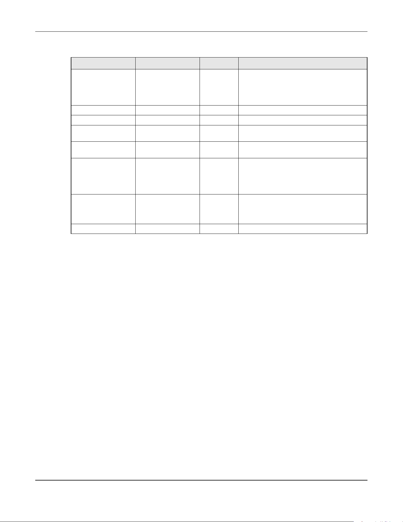
Appendix B Common Services
XGS2220 Series User’s Guide
701
SQL-NET TCP 1521 Structured Query Language is an interface to
access data on many different types of
database systems, including mainframes,
midrange systems, UNIX systems and network
servers.
SSH TCP/UDP 22 Secure Shell Remote Login Program.
STRM WORKS UDP 1558 Stream Works Protocol.
SYSLOG UDP 514 Syslog allows you to send system logs to a UNIX
server.
TACACS UDP 49 Login Host Protocol used for (Terminal Access
Controller Access Control System).
TELNET TCP 23 Telnet is the login and terminal emulation
protocol common on the Internet and in UNIX
environments. It operates over TCP/IP networks.
Its primary function is to allow users to log into
remote host systems.
TFTP UDP 69 Trivial File Transfer Protocol is an Internet file
transfer protocol similar to FTP, but uses the UDP
(User Datagram Protocol) rather than TCP
(Transmission Control Protocol).
VDOLIVE TCP 7000 Another videoconferencing solution.
Table 367 Commonly Used Services (continued)
NAME PROTOCOL PORT(S) DESCRIPTION

XGS2220 Series User’s Guide
702
APPENDIX C
IPv6
Overview
IPv6 (Internet Protocol version 6), is designed to enhance IP address size and features. The increase in
IPv6 address size to 128 bits (from the 32-bit IPv4 address) allows up to 3.4 x 10
38
IP addresses.
IPv6 Addressing
The 128-bit IPv6 address is written as eight 16-bit hexadecimal blocks separated by colons (:). This is an
example IPv6 address 2001:0db8:1a2b:0015:0000:0000:1a2f:0000.
IPv6 addresses can be abbreviated in two ways:
• Leading zeros in a block can be omitted. So 2001:0db8:1a2b:0015:0000:0000:1a2f:0000 can be
written as 2001:db8:1a2b:15:0:0:1a2f:0.
• Any number of consecutive blocks of zeros can be replaced by a double colon. A double colon can
only appear once in an IPv6 address. So 2001:0db8:0000:0000:1a2f:0000:0000:0015 can be
written as 2001:0db8::1a2f:0000:0000:0015, 2001:0db8:0000:0000:1a2f::0015,
2001:db8::1a2f:0:0:15 or 2001:db8:0:0:1a2f::15.
Prefix and Prefix Length
Similar to an IPv4 subnet mask, IPv6 uses an address prefix to represent the network address. An IPv6
prefix length specifies how many most significant bits (start from the left) in the address compose the
network address. The prefix length is written as “/x” where x is a number. For example,
2001:db8:1a2b:15::1a2f:0/32
means that the first 32 bits (2001:db8) is the subnet prefix.
Link-local Address
A link-local address uniquely identifies a device on the local network (the LAN). It is similar to a “private IP
address” in IPv4. You can have the same link-local address on multiple interfaces on a device. A link-
local unicast address has a predefined prefix of fe80::/10. The link-local unicast address format is as
follows.
Table 368 Link-local Unicast Address Format
Global Address
A global address uniquely identifies a device on the Internet. It is similar to a “public IP address” in IPv4. A
global unicast address starts with a 2 or 3.
1111 1110 10 0 Interface ID
10 bits 54 bits 64 bits
Appendix C IPv6
XGS2220 Series User’s Guide
703
Unspecified Address
An unspecified address (0:0:0:0:0:0:0:0 or ::) is used as the source address when a device does not have
its own address. It is similar to “0.0.0.0” in IPv4.
Loopback Address
A loopback address (0:0:0:0:0:0:0:1 or ::1) allows a host to send packets to itself. It is similar to “127.0.0.1”
in IPv4.
Multicast Address
In IPv6, multicast addresses provide the same functionality as IPv4 broadcast addresses. Broadcasting is
not supported in IPv6. A multicast address allows a host to send packets to all hosts in a multicast group.
Multicast scope allows you to determine the size of the multicast group. A multicast address has a
predefined prefix of ff00::/8. The following table describes some of the predefined multicast addresses.
The following table describes the multicast addresses which are reserved and cannot be assigned to a
multicast group.
Table 369 Predefined Multicast Address
MULTICAST ADDRESS DESCRIPTION
FF01:0:0:0:0:0:0:1 All hosts on a local node.
FF01:0:0:0:0:0:0:2 All routers on a local node.
FF02:0:0:0:0:0:0:1 All hosts on a local connected link.
FF02:0:0:0:0:0:0:2 All routers on a local connected link.
FF05:0:0:0:0:0:0:2 All routers on a local site.
FF05:0:0:0:0:0:1:3 All DHCP severs on a local site.
Table 370 Reserved Multicast Address
MULTICAST ADDRESS
FF00:0:0:0:0:0:0:0
FF01:0:0:0:0:0:0:0
FF02:0:0:0:0:0:0:0
FF03:0:0:0:0:0:0:0
FF04:0:0:0:0:0:0:0
FF05:0:0:0:0:0:0:0
FF06:0:0:0:0:0:0:0
FF07:0:0:0:0:0:0:0
FF08:0:0:0:0:0:0:0
FF09:0:0:0:0:0:0:0
FF0A:0:0:0:0:0:0:0
FF0B:0:0:0:0:0:0:0
FF0C:0:0:0:0:0:0:0
FF0D:0:0:0:0:0:0:0
FF0E:0:0:0:0:0:0:0
FF0F:0:0:0:0:0:0:0

Appendix C IPv6
XGS2220 Series User’s Guide
704
Subnet Masking
Both an IPv6 address and IPv6 subnet mask compose of 128-bit binary digits, which are divided into
eight 16-bit blocks and written in hexadecimal notation. Hexadecimal uses 4 bits for each character (1 –
10, A – F). Each block’s 16 bits are then represented by 4 hexadecimal characters. For example,
FFFF:FFFF:FFFF:FFFF:FC00:0000:0000:0000.
Interface ID
In IPv6, an interface ID is a 64-bit identifier. It identifies a physical interface (for example, an Ethernet
port) or a virtual interface (for example, the management IP address for a VLAN). One interface should
have a unique interface ID.
EUI-64
The EUI-64 (Extended Unique Identifier) defined by the IEEE (Institute of Electrical and Electronics
Engineers) is an interface ID format designed to adapt with IPv6. It is derived from the 48-bit (6-byte)
Ethernet MAC address as shown next. EUI-64 inserts the hex digits fffe between the third and fourth bytes
of the MAC address and complements the seventh bit of the first byte of the MAC address. See the
following example.
DHCPv6
The Dynamic Host Configuration Protocol for IPv6 (DHCPv6, RFC 3315) is a server-client protocol that
allows a DHCP server to assign and pass IPv6 network addresses, prefixes and other configuration
information to DHCP clients. DHCPv6 servers and clients exchange DHCP messages using UDP.
Each DHCP client and server has a unique DHCP Unique IDentifier (DUID), which is used for identification
when they are exchanging DHCPv6 messages. The DUID is generated from the MAC address, time,
vendor assigned ID and/or the vendor's private enterprise number registered with the IANA. It should not
change over time even after you reboot the device.
Identity Association
An Identity Association (IA) is a collection of addresses assigned to a DHCP client, through which the
server and client can manage a set of related IP addresses. Each IA must be associated with exactly
one interface. The DHCP client uses the IA assigned to an interface to obtain configuration from a DHCP
server for that interface. Each IA consists of a unique IAID and associated IP information.
The IA type is the type of address in the IA. Each IA holds one type of address. IA_NA means an identity
association for non-temporary addresses and IA_TA is an identity association for temporary addresses.
An IA_NA option contains the T1 and T2 fields, but an IA_TA option does not. The DHCPv6 server uses T1
and T2 to control the time at which the client contacts with the server to extend the lifetimes on any
addresses in the IA_NA before the lifetimes expire. After T1, the client sends the server (S1) (from which
the addresses in the IA_NA were obtained) a Renew message. If the time T2 is reached and the server
does not respond, the client sends a Rebind message to any available server (S2). For an IA_TA, the
Table 371
MAC 00 : 13 : 49 : 12 : 34 : 56
Table 372
EUI-64 02 : 13 : 49 : FF : FE : 12 : 34 : 56
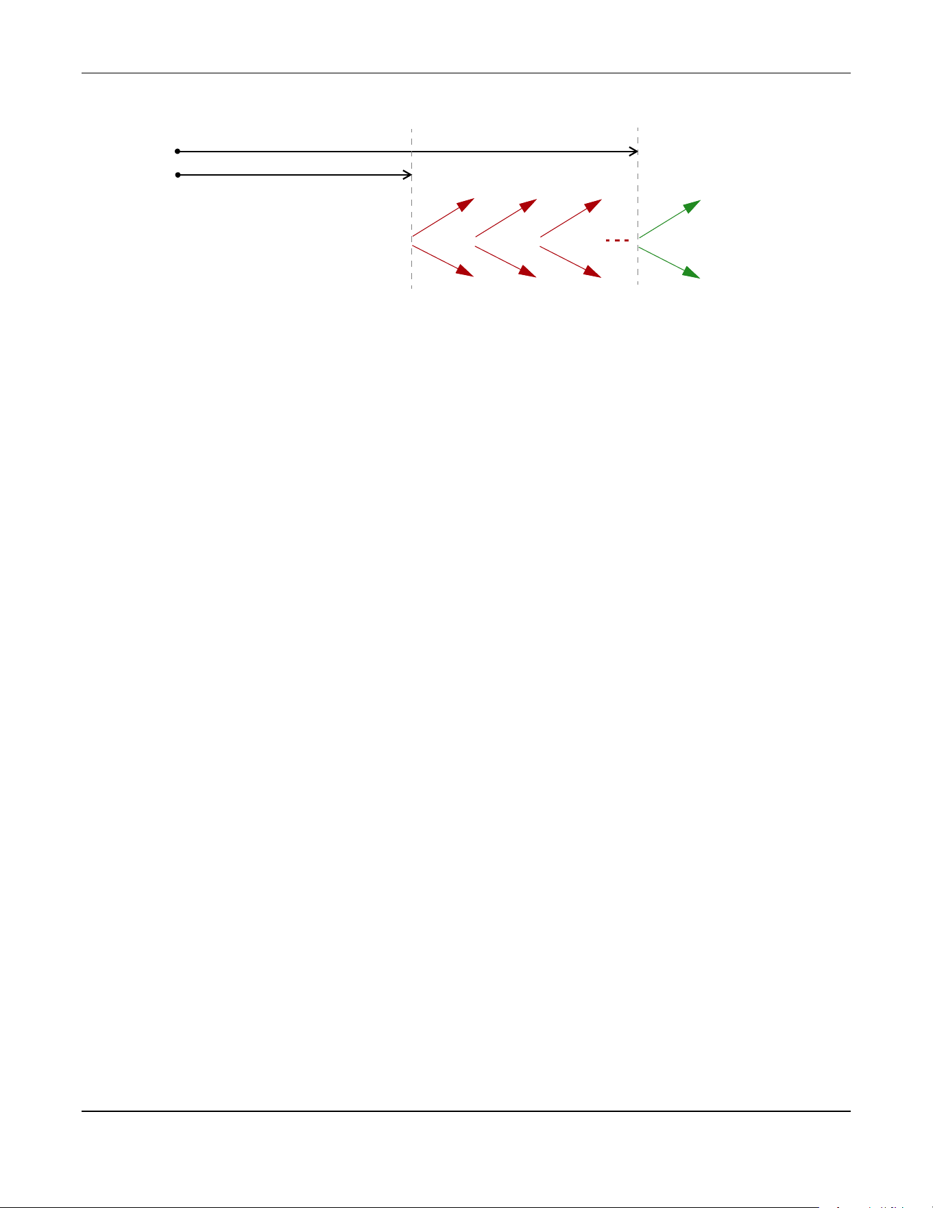
Appendix C IPv6
XGS2220 Series User’s Guide
705
client may send a Renew or Rebind message at the client's discretion.
DHCP Relay Agent
A DHCP relay agent is on the same network as the DHCP clients and helps forward messages between
the DHCP server and clients. When a client cannot use its link-local address and a well-known multicast
address to locate a DHCP server on its network, it then needs a DHCP relay agent to send a message to
a DHCP server that is not attached to the same network.
The DHCP relay agent can add the remote identification (remote-ID) option and the interface-ID option
to the Relay-Forward DHCPv6 messages. The remote-ID option carries a user-defined string, such as the
system name. The interface-ID option provides slot number, port information and the VLAN ID to the
DHCPv6 server. The remote-ID option (if any) is stripped from the Relay-Reply messages before the relay
agent sends the packets to the clients. The DHCP server copies the interface-ID option from the Relay-
Forward message into the Relay-Reply message and sends it to the relay agent. The interface-ID should
not change even after the relay agent restarts.
Prefix Delegation
Prefix delegation enables an IPv6 router to use the IPv6 prefix (network address) received from the ISP (or
a connected uplink router) for its LAN. The Switch uses the received IPv6 prefix (for example, 2001:db2::/
48) to generate its LAN IP address. Through sending Router Advertisements (RAs) regularly by multicast,
the Switch passes the IPv6 prefix information to its LAN hosts. The hosts then can use the prefix to
generate their IPv6 addresses.
ICMPv6
Internet Control Message Protocol for IPv6 (ICMPv6 or ICMP for IPv6) is defined in RFC 4443. ICMPv6 has
a preceding Next Header value of 58, which is different from the value used to identify ICMP for IPv4.
ICMPv6 is an integral part of IPv6. IPv6 nodes use ICMPv6 to report errors encountered in packet
processing and perform other diagnostic functions, such as "ping".
Neighbor Discovery Protocol (NDP)
The Neighbor Discovery Protocol (NDP) is a protocol used to discover other IPv6 devices and track
neighbor’s reachability in a network. An IPv6 device uses the following ICMPv6 messages types:
• Neighbor solicitation: A request from a host to determine a neighbor’s link-layer address (MAC
address) and detect if the neighbor is still reachable. A neighbor being “reachable” means it
responds to a neighbor solicitation message (from the host) with a neighbor advertisement message.
• Neighbor advertisement: A response from a node to announce its link-layer address.
• Router solicitation: A request from a host to locate a router that can act as the default router and
T1
T2
Renew
Rebind
Rebind
to S1
Renew
to S1
Renew
to S1
Renew
to S1
Renew
to S1
Renew
to S1
to S2
to S2

Appendix C IPv6
XGS2220 Series User’s Guide
706
forward packets.
• Router advertisement: A response to a router solicitation or a periodical multicast advertisement from
a router to advertise its presence and other parameters.
IPv6 Cache
An IPv6 host is required to have a neighbor cache, destination cache, prefix list and default router list.
The Switch maintains and updates its IPv6 caches constantly using the information from response
messages. In IPv6, the Switch configures a link-local address automatically, and then sends a neighbor
solicitation message to check if the address is unique. If there is an address to be resolved or verified, the
Switch also sends out a neighbor solicitation message. When the Switch receives a neighbor
advertisement in response, it stores the neighbor’s link-layer address in the neighbor cache. When the
Switch uses a router solicitation message to query for a router and receives a router advertisement
message, it adds the router’s information to the neighbor cache, prefix list and destination cache. The
Switch creates an entry in the default router list cache if the router can be used as a default router.
When the Switch needs to send a packet, it first consults the destination cache to determine the next
hop. If there is no matching entry in the destination cache, the Switch uses the prefix list to determine
whether the destination address is on-link and can be reached directly without passing through a router.
If the address is onlink, the address is considered as the next hop. Otherwise, the Switch determines the
next-hop from the default router list or routing table. Once the next hop IP address is known, the Switch
looks into the neighbor cache to get the link-layer address and sends the packet when the neighbor is
reachable. If the Switch cannot find an entry in the neighbor cache or the state for the neighbor is not
reachable, it starts the address resolution process. This helps reduce the number of IPv6 solicitation and
advertisement messages.
Multicast Listener Discovery
The Multicast Listener Discovery (MLD) protocol (defined in RFC 2710) is derived from IPv4's Internet
Group Management Protocol version 2 (IGMPv2). MLD uses ICMPv6 message types, rather than IGMP
message types. MLDv1 is equivalent to IGMPv2 and MLDv2 is equivalent to IGMPv3.
MLD allows an IPv6 switch or router to discover the presence of MLD listeners who wish to receive
multicast packets and the IP addresses of multicast groups the hosts want to join on its network.
MLD snooping and MLD proxy are analogous to IGMP snooping and IGMP proxy in IPv4.
MLD filtering controls which multicast groups a port can join.
MLD Messages
A multicast router or switch periodically sends general queries to MLD hosts to update the multicast
forwarding table. When an MLD host wants to join a multicast group, it sends an MLD Report message
for that address.
An MLD Done message is equivalent to an IGMP Leave message. When an MLD host wants to leave a
multicast group, it can send a Done message to the router or switch. The router or switch then sends a
group-specific query to the port on which the Done message is received to determine if other devices
connected to this port should remain in the group.
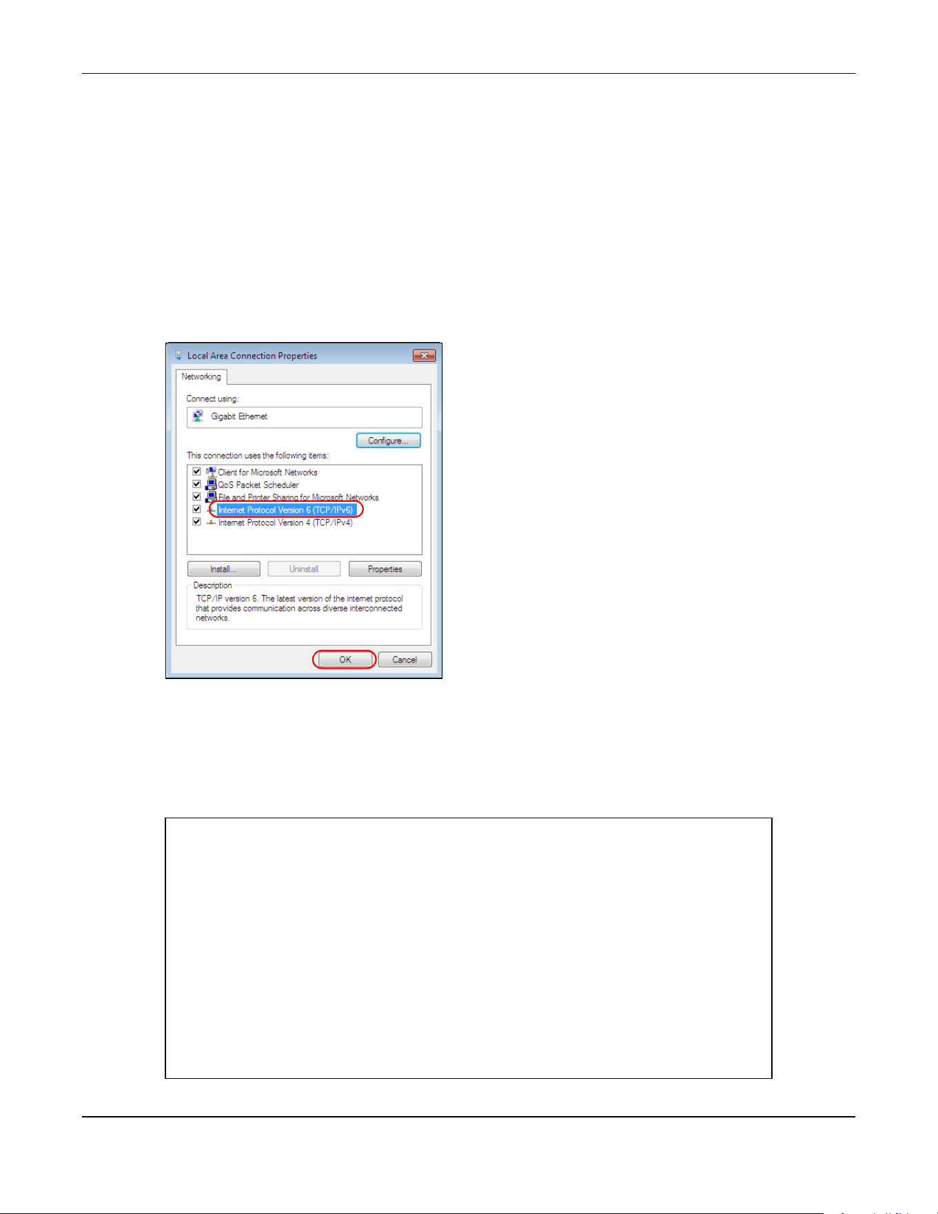
Appendix C IPv6
XGS2220 Series User’s Guide
707
Example – Enabling IPv6 on Windows 7
Windows 7 supports IPv6 by default. DHCPv6 is also enabled when you enable IPv6 on a Windows 7
computer.
To enable IPv6 in Windows 7:
1 Select Control Panel > Network and Sharing Center > Local Area Connection.
2 Select the Internet Protocol Version 6 (TCP/IPv6) check box to enable it.
3 Click OK to save the change.
4 Click Close to exit the Local Area Connection Status screen.
5 Select Start > All Programs > Accessories > Command Prompt.
6 Use the ipconfig command to check your dynamic IPv6 address. This example shows a global address
(2001:b021:2d::1000) obtained from a DHCP server.
C:\>ipconfig
Windows IP Configuration
Ethernet adapter Local Area Connection:
Connection-specific DNS Suffix . :
IPv6 Address. . . . . . . . . . . : 2001:b021:2d::1000
Link-local IPv6 Address . . . . . : fe80::25d8:dcab:c80a:5189%11
IPv4 Address. . . . . . . . . . . : 172.16.100.61
Subnet Mask . . . . . . . . . . . : 255.255.255.0
Default Gateway . . . . . . . . . : fe80::213:49ff:feaa:7125%11
172.16.100.254
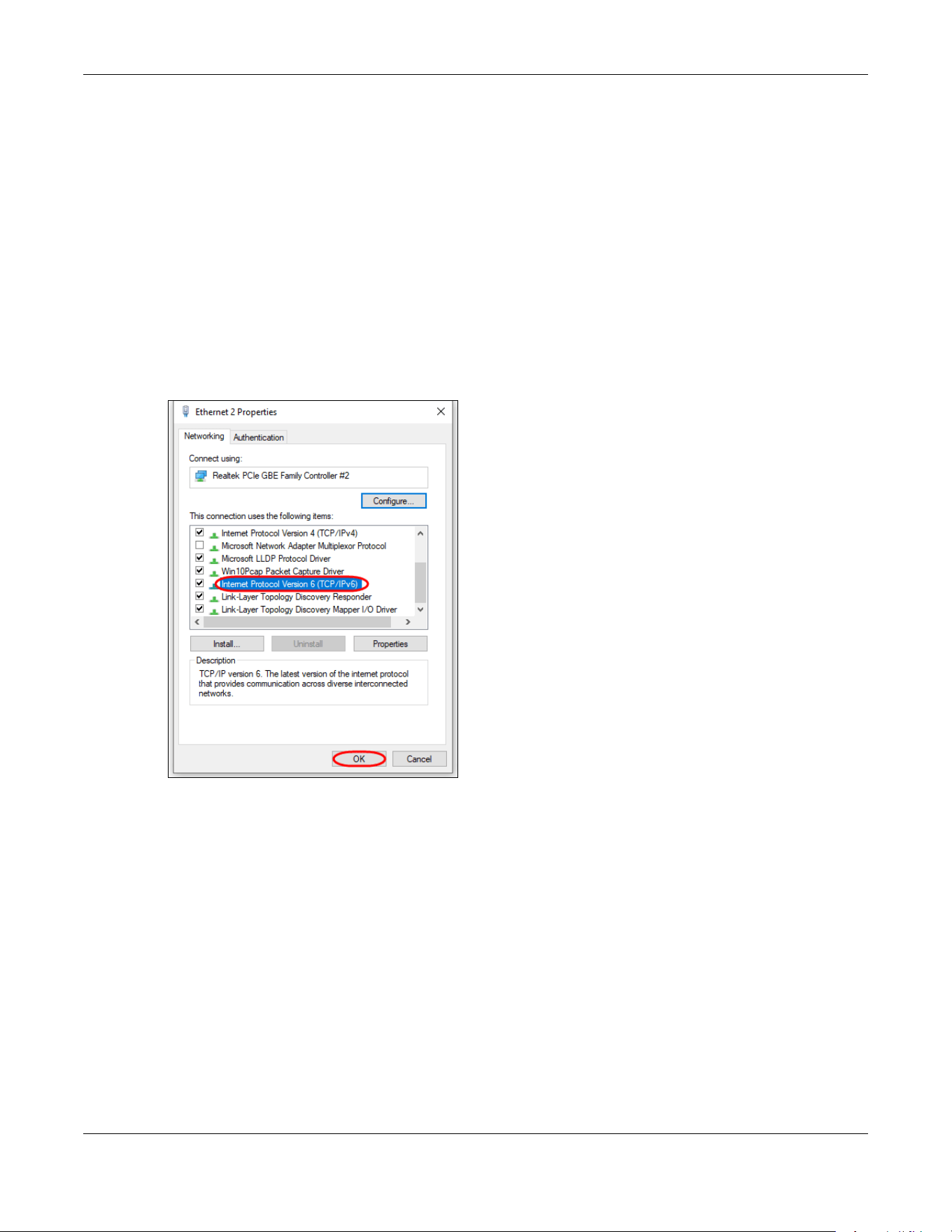
Appendix C IPv6
XGS2220 Series User’s Guide
708
Example – Enabling IPv6 on Windows 10
Windows 10 supports IPv6 by default. DHCPv6 is enabled when you enable IPv6 on a Windows 10 PC.
To enable IPv6 in Windows 10:
1 Select Control Panel > Network and Sharing Center.
2 On the left side of the Network and Sharing Center, select Change adapter settings.
3 Right-click your network connection and select Properties.
4 Select the Internet Protocol Version 6 (TCP/IPv6) check box to enable it.
5 Click OK to save the changes for the selected network adapter.
6 Click OK to exit the selected network adapter Properties screen.
Example – Enabling DHCPv6 on Windows 10
Windows 10 supports DHCPv6 by default. To enable DHCPv6 client on your computer:
1 Select Start > Settings > Network & Internet.
2 On the left side of the Network & Internet, select Ethernet. Then select the Ethernet network you are
connected to.
3 Under IP assignment, select Edit.
4 Under Edit IP settings, select Automatic (DHCP) or Manual. Then click Save.
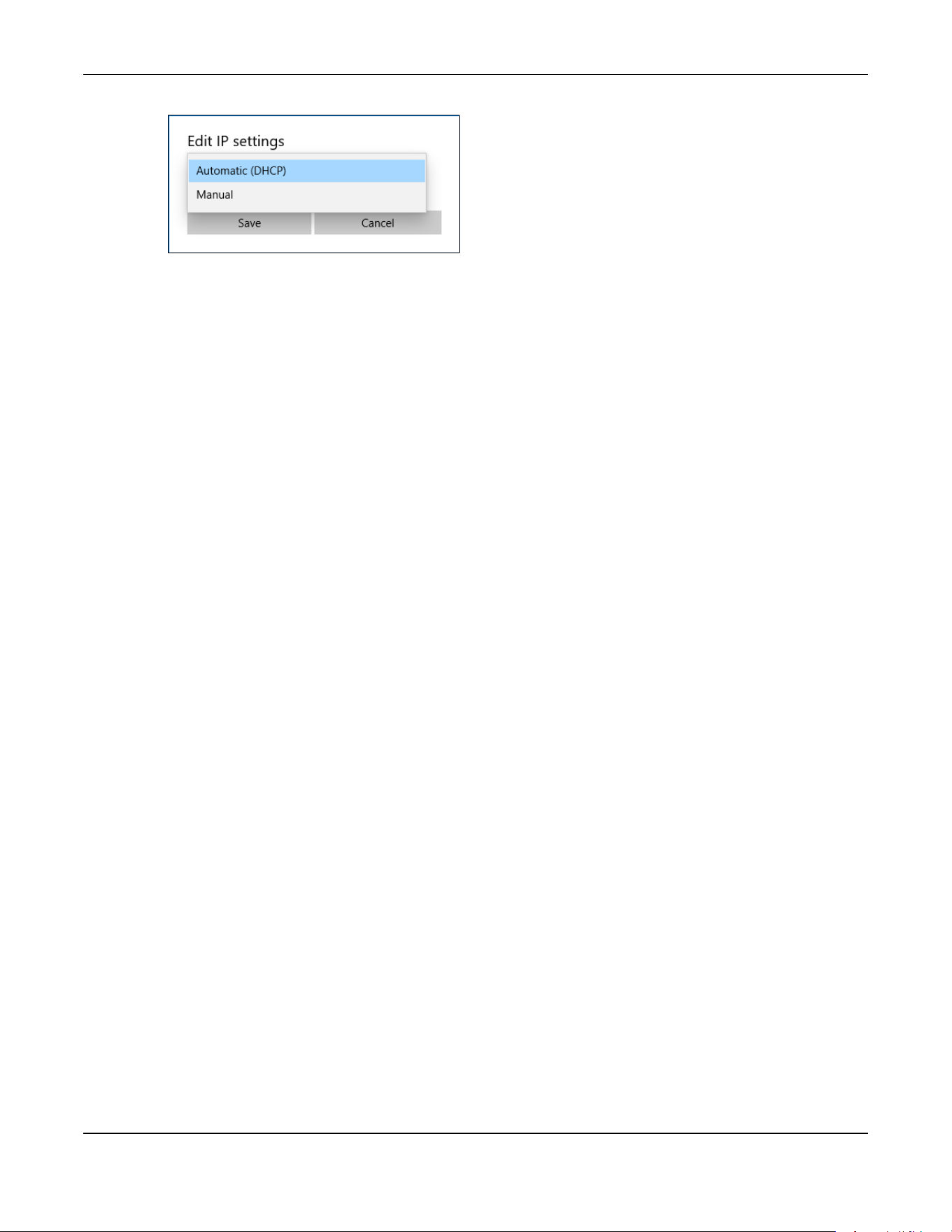
Appendix C IPv6
XGS2220 Series User’s Guide
709
• When you select Automatic (DHCP), the IP address settings and DNS server address setting are set
automatically by your router.
• When you select Manual, you can manually set your IP address settings and DNS server address.
Now your computer can obtain an IPv6 address from a DHCPv6 server.

XGS2220 Series User’s Guide
710
APPENDIX D
Legal Information
Copyright
Copyright © 2023 by Zyxel and/or its affiliates.
The contents of this publication may not be reproduced in any part or as a whole, transcribed, stored in a retrieval system, translated into any
language, or transmitted in any form or by any means, electronic, mechanical, magnetic, optical, chemical, photocopying, manual, or
otherwise, without the prior written permission of Zyxel and/or its affiliates.
Published by Zyxel and/or its affiliates. All rights reserved.
Disclaimer
Zyxel does not assume any liability arising out of the application or use of any products, or software described herein. Neither does it convey any
license under its patent rights nor the patent rights of others. Zyxel further reserves the right to make changes in any products described herein
without notice. This publication is subject to change without notice.
Regulatory Notice and Statement
United States of America
The following information applies if you use the product within USA area.
US Importer: Zyxel Communications, Inc, 1130 North Miller Street Anaheim, CA92806-2001, https://www.zyxel.com/us/en/
Federal Communications Commission (FCC) EMC Statement
• This device complies with Part 15 of FCC rules. Operation is subject to the following two conditions:
(1) This device may not cause harmful interference.
(2) This device must accept any interference received, including interference that may cause undesired operations.
• Changes or modifications not expressly approved by the party responsible for compliance could void the user’s authority to operate the
equipment.
• This equipment has been tested and found to comply with the limits for a Class A digital device, pursuant to part 15 of the FCC Rules. These
limits are designed to provide reasonable protection against harmful interference when the equipment is operated in a commercial
environment. This equipment generates, uses, and can radiate radio frequency energy and, if not installed and used in accordance with the
instruction manual, may cause harmful interference to radio communications. Operation of this equipment in a residential area is likely to
cause harmful interference in which case the user will be required to correct the interference at his own expense.
Canada
The following information applies if you use the product within Canada area.
Innovation, Science and Economic Development Canada ICES statement
CAN ICES-3 (A)/NMB-3(A)
European Union and United Kingdom
The following information applies if you use the product within the European Union and United Kingdom.
EMC statement
WARNING: This equipment is compliant with Class A of EN55032. In a residential environment this equipment may cause radio interference.

Appendix D Legal Information
XGS2220 Series User’s Guide
711
List of National Codes
Safety Warnings
• To avoid possible eye injury, do NOT look into an operating fiber-optic module’s connector.
• Do NOT use this device near water, for example, in a wet basement or near a swimming pool.
• Do NOT expose your device to dampness, dust or corrosive liquids.
• Do NOT store things on the device.
• Do NOT obstruct the device ventilation slots as insufficient airflow may harm your device. For example, do not place the device in an
enclosed space such as a box or on a very soft surface such as a bed or sofa.
• Do NOT install or service this device during a thunderstorm. There is a remote risk of electric shock from lightning.
• Connect ONLY suitable accessories to the device.
• Do NOT open the device or unit. Opening or removing covers can expose you to dangerous high voltage points or other risks. Only qualified
service personnel should service or disassemble this device. Please contact your vendor for further information.
• Make sure to connect the cables to the correct ports.
• Place connecting cables carefully so that no one will step on them or stumble over them.
• Always disconnect all cables from this device before servicing or disassembling.
• Do NOT remove the plug and connect it to a power outlet by itself; always attach the plug to the power adaptor first before connecting it to
a power outlet.
• Do NOT allow anything to rest on the power adaptor or cord and do NOT place the device where anyone can walk on the power adaptor
or cord.
• Please use the provided or designated connection cables/power cables/adaptors. Connect it to the right supply voltage (for example, 120V
AC in North America or 230V AC in Europe). If the power adaptor or cord is damaged, it might cause electrocution. Remove it from the
device and the power source, repairing the power adapter or cord is prohibited. Contact your local vendor to order a new one.
• Do NOT use the device outside, and make sure all the connections are indoors. There is a remote risk of electric shock from lightning.
• CAUTION: RISK OF EXPLOSION IF BATTERY IS REPLACED BY AN INCORRECT TYPE, DISPOSE OF USED BATTERIES ACCORDING TO THE INSTRUCTION.
Dispose them at the applicable collection point for the recycling of electrical and electronic device. For detailed information about
recycling of this device, please contact your local city office, your household waste disposal service or the store where you purchased the
device.
• Use ONLY power wires of the appropriate wire gauge for your device. Connect it to a power supply of the correct voltage.
• Fuse Warning! Replace a fuse only with a fuse of the same type and rating.
• The POE (Power over Ethernet) devices that supply or receive power and their connected Ethernet cables must all be completely indoors.
• The following warning statements apply, where the disconnect device is not incorporated in the device or where the plug on the power
supply cord is intended to serve as the disconnect device,
– For PERMANENTLY CONNECTED DEVICES, a readily accessible disconnect device shall be incorporated external to the device;
– For PLUGGABLE DEVICES, the socket-outlet shall be installed near the device and shall be easily accessible.
• This device must be grounded by qualified service personnel. Never defeat the ground conductor or operate the device in the absence of a
suitably installed ground conductor. Contact the appropriate electrical inspection authority or an electrician if you are uncertain that
suitable grounding is available.
• If your device has an earthing screw (frame ground), connect the screw to a ground terminal using an appropriate AWG ground wire. Do this
before you make other connections.
• If your device has no earthing screw, but has a 3-prong power plug, make sure to connect the plug to a 3-hole earthed socket.
• When connecting or disconnecting power to hot-pluggable power supplies, if offered with your system, observe the following guidelines:
– Install the power supply before connecting the power cable to the power supply.
– Unplug the power cable before removing the power supply.
– If the system has multiple sources of power, disconnect power from the system by unplugging all power cables from the power supply.
• Do not put the device in a place that is humid, dusty or has extreme temperatures as these conditions may harm your device.
• Please refer to the device back label, datasheet, box specifications or catalog information for the power rating of the device and operating
temperature.
COUNTRY ISO 3166 2 LETTER CODE COUNTRY ISO 3166 2 LETTER CODE
Austria AT Liechtenstein LI
Belgium BE Lithuania LT
Bulgaria BG Luxembourg LU
Croatia HR Malta MT
Cyprus CY Netherlands NL
Czech Republic CR Norway NO
Denmark DK Poland PL
Estonia EE Portugal PT
Finland FI Romania RO
France FR Serbia RS
Germany DE Slovakia SK
Greece GR Slovenia SI
Hungary HU Spain ES
Iceland IS Sweden SE
Ireland IE Switzerland CH
Italy IT Turkey TR
Latvia LV United Kingdom GB
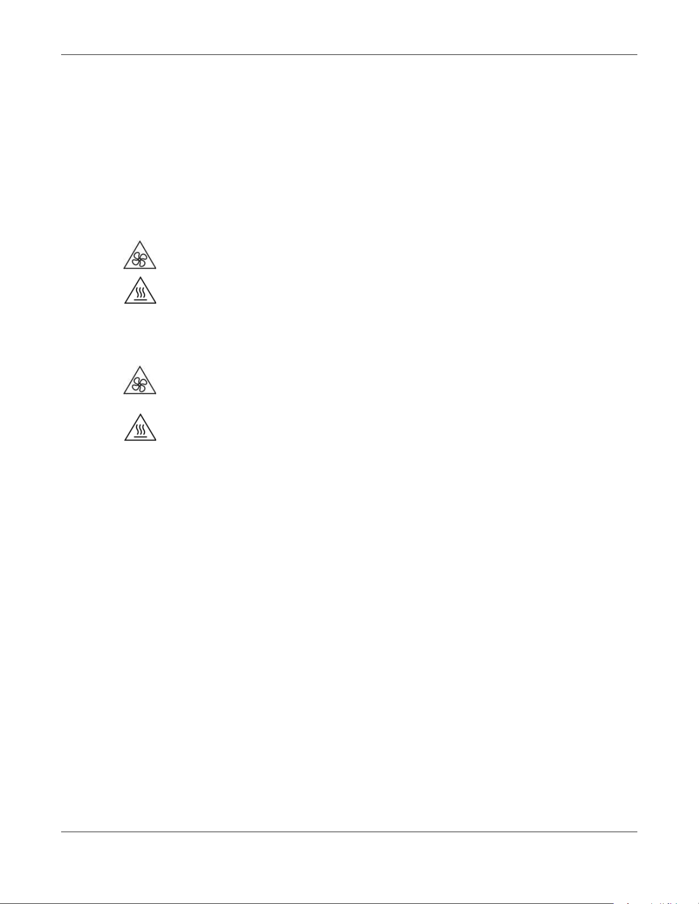
Appendix D Legal Information
XGS2220 Series User’s Guide
712
• CLASS 1 LASER PRODUCT
• APPAREIL À LASER DE CLASS 1
• PRODUCT COMPLIES WITH 21 CFR 1040.10 AND 1040.11.
• PRODUIT CONFORME SELON 21 CFR 1040.10 ET 1040.11.
Important Safety Instructions
1 Warning! Energy Hazard. Remove all metal jewelry, watches, and so on from your hands and wrists
before serving the Switch.
2 Caution! The RJ-45 jacks are not used for telephone line connection.
3 Hazardous Moving Parts. Keep body parts away from fan blades.
4 Hot Surface. Do not touch.
1 Avertissement: Risque de choc électrique. Retirer tout bijoux en métal et votre montre de vos mains et
poignets avant de manipuler cet appareil.
2 Attention: Les câbles RJ-45 ne doivent pas être utilisés pour les connections téléphoniques.
3 Mobilité des pièces détachées. S'assurer que les pièces détachées ne sont pas en contact avec
les pales du ventilateur.
4 Surface brûlante. Ne pas toucher.
Environment Statement
Disposal and Recycling Information
The symbol below means that according to local regulations your product and/or its battery shall be disposed of separately from domestic
waste. If this product is end of life, take it to a recycling station designated by local authorities. At the time of disposal, the separate collection of
your product and/or its battery will help save natural resources and ensure that the environment is sustainable development.
Die folgende Symbol bedeutet, dass Ihr Produkt und/oder seine Batterie gemäß den örtlichen Bestimmungen getrennt vom Hausmüll entsorgt
werden muss. Wenden Sie sich an eine Recyclingstation, wenn dieses Produkt das Ende seiner Lebensdauer erreicht hat. Zum Zeitpunkt der
Entsorgung wird die getrennte Sammlung von Produkt und/oder seiner Batterie dazu beitragen, natürliche Ressourcen zu sparen und die Umwelt
und die menschliche Gesundheit zu schützen.
El símbolo de abajo indica que según las regulaciones locales, su producto y/o su batería deberán depositarse como basura separada de la
doméstica. Cuando este producto alcance el final de su vida útil, llévelo a un punto limpio. Cuando llegue el momento de desechar el
producto, la recogida por separado éste y/o su batería ayudará a salvar los recursos naturales y a proteger la salud humana y
medioambiental.
Le symbole ci-dessous signifie que selon les réglementations locales votre produit et/ou sa batterie doivent être éliminés séparément des ordures
ménagères. Lorsque ce produit atteint sa fin de vie, amenez-le à un centre de recyclage. Au moment de la mise au rebut, la collecte séparée
de votre produit et/ou de sa batterie aidera à économiser les ressources naturelles et protéger l'environnement et la santé humaine.
Il simbolo sotto significa che secondo i regolamenti locali il vostro prodotto e/o batteria deve essere smaltito separatamente dai rifiuti domestici.
Quando questo prodotto raggiunge la fine della vita di servizio portarlo a una stazione di riciclaggio. Al momento dello smaltimento, la raccolta
separata del vostro prodotto e/o della sua batteria aiuta a risparmiare risorse naturali e a proteggere l'ambiente e la salute umana.
Symbolen innebär att enligt lokal lagstiftning ska produkten och/eller dess batteri kastas separat från hushållsavfallet. När den här produkten når
slutet av sin livslängd ska du ta den till en återvinningsstation. Vid tiden för kasseringen bidrar du till en bättre miljö och mänsklig hälsa genom att
göra dig av med den på ett återvinningsställe.

Appendix D Legal Information
XGS2220 Series User’s Guide
713
台灣
以下訊息僅適用於產品銷售至台灣地區
• 這是甲類的資訊產品,在居住的環境中使用時,可能會造成射頻干擾,在這種情況下,使用者會被要求採取某些適當的對策。
• 為避免電磁干擾,本產品不應安裝或使用於住宅環境。
安全警告 – 為了您的安全,請先閱讀以下警告及指示 :
• 請勿將此產品接近水、火焰或放置在高溫的環境。
• 避免設備接觸
– 任何液體 - 切勿讓設備接觸水、雨水、高濕度、污水腐蝕性的液體或其他水份。
– 灰塵及污物 - 切勿接觸灰塵、污物、沙土、食物或其他不合適的材料。
• 雷雨天氣時,不要安裝或維修此設備。有遭受電擊的風險。
• 切勿重摔或撞擊設備,並勿使用不正確的電源變壓器。
• 若接上不正確的電源變壓器會有爆炸的風險。
• 請勿隨意更換產品內的電池。
• 如果更換不正確之電池型式,會有爆炸的風險,請依製造商說明書處理使用過之電池。
• 請將廢電池丟棄在適當的電器或電子設備回收處。
• 請勿將設備解體。
• 請勿阻礙設備的散熱孔,空氣對流不足將會造成設備損害。
• 請使用隨貨提供或指定的連接線 / 電源線 / 電源變壓器,將其連接到合適的供應電壓 ( 如 : 台灣供應電壓 110 伏特 )。
• 假若電源變壓器或電源變壓器的纜線損壞,請從插座拔除,若您還繼續插電使用,會有觸電死亡的風險。
• 請勿試圖修理電源變壓器或電源變壓器的纜線,若有毀損,請直接聯絡您購買的店家,購買⼀個新的電源變壓器。
• 請勿將此設備安裝於室外,此設備僅適合放置於室內。
• 請勿隨⼀般垃圾丟棄。
• 請參閱產品背貼上的設備額定功率。
• 請參考產品型錄或是彩盒上的作業溫度。
• 設備必須接地,接地導線不允許被破壞或沒有適當安裝接地導線,如果不確定接地方式是否符合要求可聯繫相應的電氣檢驗機構檢驗。
• 如果您提供的系統中有提供熱插拔電源,連接或斷開電源請遵循以下指導原則 :
– 先連接電源線至設備連,再連接電源。
– 先斷開電源再拔除連接至設備的電源線。
– 如果系統有多個電源,需拔除所有連接至電源的電源線再關閉設備電源。
• 產品沒有斷電裝置或者採用電源線的插頭視為斷電裝置的⼀部分,以下警語將適用 :
– 對永久連接之設備, 在設備外部須安裝可觸及之斷電裝置;
– 對插接式之設備, 插座必須接近安裝之地點而且是易於觸及的。
About the Symbols
Various symbols are used in this product to ensure correct usage, to prevent danger to the user and others, and to prevent property damage.
The meaning of these symbols are described below. It is important that you read these descriptions thoroughly and fully understand the
contents.
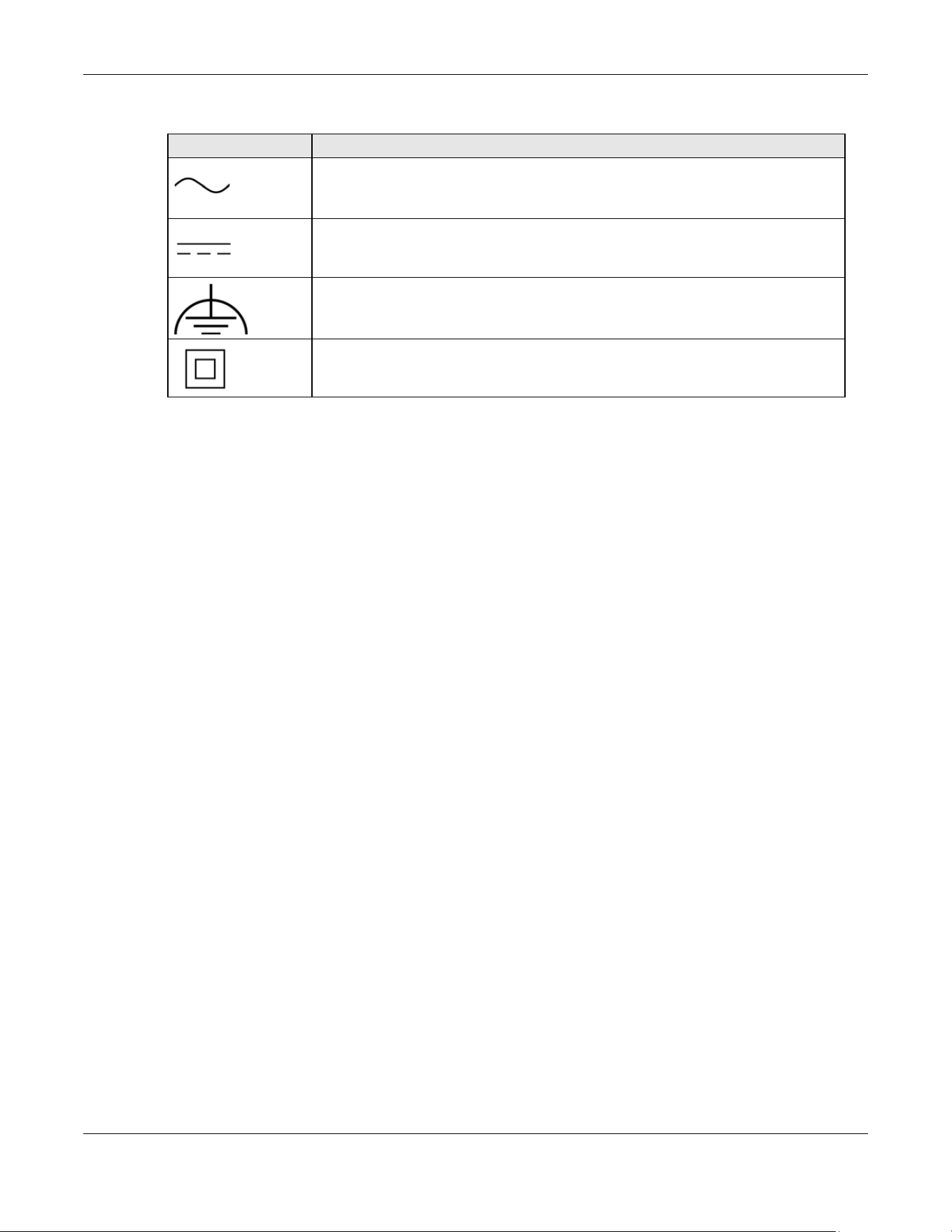
Appendix D Legal Information
XGS2220 Series User’s Guide
714
Explanation of the Symbols
Viewing Certifications
Go to http://www.zyxel.com to view this product’s documentation and certifications.
Zyxel Limited Warranty
Zyxel warrants to the original end user (purchaser) that this product is free from any defects in material or workmanship for a specific period (the
Warranty Period) from the date of purchase. The Warranty Period varies by region. Check with your vendor and/or the authorized Zyxel local
distributor for details about the Warranty Period of this product. During the warranty period, and upon proof of purchase, should the product
have indications of failure due to faulty workmanship and/or materials, Zyxel will, at its discretion, repair or replace the defective products or
components without charge for either parts or labor, and to whatever extent it shall deem necessary to restore the product or components to
proper operating condition. Any replacement will consist of a new or re-manufactured functionally equivalent product of equal or higher value,
and will be solely at the discretion of Zyxel. This warranty shall not apply if the product has been modified, misused, tampered with, damaged by
an act of God, or subjected to abnormal working conditions.
Note
Repair or replacement, as provided under this warranty, is the exclusive remedy of the purchaser. This warranty is in lieu of all other warranties,
express or implied, including any implied warranty of merchantability or fitness for a particular use or purpose. Zyxel shall in no event be held
liable for indirect or consequential damages of any kind to the purchaser.
To obtain the services of this warranty, contact your vendor. You may also refer to the warranty policy for the region in which you bought the
device at https://www.zyxel.com/global/en/support/warranty-information.
Registration
Register your product online at www.zyxel.com to receive email notices of firmware upgrades and related information.
Trademarks
The trademarks mentioned in this publication are used for identification purposes only and may be properties of their respective owners.
SYMBOL EXPLANATION
Alternating current (AC):
AC is an electric current in which the flow of electric charge periodically reverses direction.
Direct current (DC):
DC if the unidirectional flow or movement of electric charge carriers.
Earth; ground:
A wiring terminal intended for connection of a Protective Earthing Conductor.
Class II equipment:
The method of protection against electric shock in the case of class II equipment is either double insulation
or reinforced insulation.

Index
XGS2220 Series User’s Guide
715
Index
Numbers
10 Gigabit port
requirement for maximum performance 29
10G port 29
802.1P priority 293, 659
A
AAA 485
accounting 485
authentication 485
authorization 485
AAA (Authentication, Authorization and
Accounting) 485
access control
account security 501
limitations 499, 679
login account 190, 639
overview 499, 678
remote management 500, 680
service port 499, 679
SNMP 198
account security 501
Account Security screen 502
accounting
setup 490
Address Resolution Protocol (ARP) 124, 460, 617, 618
admin 502
administrator password 62, 191, 640
age 402
aging time 213
air circulation
for cooling 41
All connected
Setting Wizard 440
anti-arpscan 524
blocked hosts 526
host threshold 527
status 525
trusted hosts 529
applications
backbone 36
bridging 37
fiber uplink 37
IEEE 802.1Q VLAN 38
PoE 36
switched workgroup 37
ARP
how it works 460
learning mode 460
overview 460
ARP (Address Resolution Protocol)
124
ARP inspection 546, 581
and MAC filter 582
configuring 583
syslog messages 582
trusted ports 582
ARP Learning screen 462
ARP scan 524
ARP Setup screen 462
ARP Table screen 124
ARP-Reply 461
ARP-Request 462
authentication
setup 490
authentication, authorization and accounting 485
authorization
privilege levels 493
setup 490
authorized technician
install the Switch 41
auto PD recovery 221
enable 221
restart 221
use LLDP or ping 221
auto-crossover port 47
automatic PD recovery
create 223
automatic VLAN registration 416, 672
auto-MDIX port 47

Index
XGS2220 Series User’s Guide
716
B
back up
configuration file 613, 683
bandwidth control 371, 373
egress rate 373
ingress rate 373
setup 371
Bandwidth Control screen 371
basic setup tutorial 106
binding table 546
build 551
building 546
BPDU (Bridge Protocol Data Units) 531
BPDU guard 531
and Errdisable Recovery 531
port status 531
BPDUs 379
Bridge Protocol Data Units 531
Bridge Protocol Data Units (BPDUs) 379
bridging application 37
broadcast storm control 535
Wizard 83
C
cable type
bandwidth capacity 30
distance limitation 30
transmission speed 30
cables
supported 36
Cat 5 cable 29
Cat 5e cable 29
Cat 6 cable 29
Cat 6a cable 29
CDP 304
Certificates screen 604
certifications
viewing 714
CFI (Canonical Format Indicator) 416, 671
changing the password 97
Cisco Discovery Protocol, see CDP
CIST 408
Class of Service 360
classifier 509
and QoS 509
example 516
logging 515
match order 515
overview 509
setup 510, 512
status 510
clearance
Switch installation 41
cloning a port, see port cloning
Cloud Connection Status 120
cluster management 608
and switch passwords 611
cluster manager 608, 610
cluster member 608
cluster member firmware upgrade 612
network example 608
setup 609
specification 608
status 608
switch models 608
VID 610
Web Configurator 611
Cluster Management Configuration screen 609
cluster manager 608
Common and Internal Spanning Tree, see CIST 408
Config 1 626
Config 2 626
configuration 480
back up 40
change running config 625,
685
saving 97
configuration file 98
backup 613, 683
restore 98, 613, 682
save 616
Configure Clone screen 617
contact information 694
copying port settings, see port cloning
copyright 710
CoS 360
CPU management port 439
CPU protection 538
crossover Ethernet cable 46

Index
XGS2220 Series User’s Guide
717
Current Configuration 686
current date 161, 637
current time 161, 636
Custom Default 626, 686
customer support 694
D
date
current 161, 637
daylight saving time 161, 637
DDMI Details screen 145
DDMI screen 144
debug port 49
device back label
Switch 33
DHCP 466
configuration options 467
modes 466
DHCP (Dynamic Host Configuration Protocol) 466
DHCP Option 82 Profile screen 467, 468
DHCP relay
configure 113
tutorial 110
DHCP relay agent 705
DHCP relay option 82 562
DHCP server
block 551
DHCP snooping 106, 546, 551, 561
configure 562
DHCP relay option 82 562
trusted ports 561
untrusted ports 561
DHCP snooping database 561
DHCP Status screen 467
DHCP Unique IDentifier (DUID) 704
DHCP-assigned IP 690
DHCPv4
global relay 469
global relay example 471
option 82 profiles 467, 468
DHCPv6
enable in Windows 10 708
DHCPv6 client 39
DHCPv6 Client Setup screen 188
DHCPv6 relay 39
interface-ID 475
remote-ID 475
DHCPv6 Relay screen 475, 476
diagnostics
ping 621
Differentiated Service (DiffServ) 360
DiffServ 360
activate
361
DS field 360
DSCP 360
network example 361
PHB 360
service level 360
DiffServ Code Points 360
Digital Diagnostics Monitoring Interface 144
disclaimer 710
disposal and recycling information
EU 712
double-tagged frames 450
DS (Differentiated Services) 360
DSCP 360
what it does 360
dual firmware images 623, 684
duplex mode 46
dust plug 48
Dynamic Host Configuration Protocol for IPv6
(DHCPv6) 704
dynamic link aggregation 234
E
egress port 440
egress rate 373
electrical inspection authority 51
electrician 52
electrostatic discharge (ESD) 47
EMC statement 710
Environment Statement 712
Errdisable Detect screen 543
Errdisable Recovery screen 544
errdisable status 541
error disable 538

Index
XGS2220 Series User’s Guide
718
control packets 541
CPU protection 541
detect 543
recovery 544
status 539
error-disable recovery 538
Ethernet broadcast address 124, 460
Ethernet MAC 152, 632
Ethernet OAM 272
Ethernet port
auto-crossover 46
auto-negotiating 46
Ethernet settings
default 47
external authentication server 486
F
Factory Default 626, 686
fan speed 153
FCC interference statement 710
fiber cable
connecting 48
removal 49
file transfer using FTP
command example 606
filename convention, configuration
file names 606
filtering 410
rules 410
filtering database, MAC table 130
Filtering screen 410
firmware 632
upgrade 612, 623, 684
ZyNOS 152
Firmware Upgrade screen 623, 684
flow control 293, 659
back pressure 293, 659
IEEE802.3x 293, 659
forwarding
delay 402
frames
tagged 425, 678
untagged 425, 678
freestanding installation
precautions 42
front panel 45
FTP 605
file transfer procedure 607
restrictions over WAN 607
full duplex
Ethernet port 46
G
GARP (Generic Attribute Registration Protocol) 416,
672
GARP timer 213, 416, 672
general setup 160
General Setup screen 160, 635
getting help 99
gigabit ports 46
GMT (Greenwich Mean Time) 161, 637
gratuitous ARP 461
green Ethernet 230
and uplink port 230
auto power down 230
EEE 230
short reach 230
grounding
for safety 50
GVRP 672
GVRP (GARP VLAN Registration Protocol) 417, 672
H
half duplex
Ethernet port 46
hardware installation 41
hardware monitor 152, 153, 632
hardware overview 45
hello time 402
hops 402
HTTPS 505
certificates 505
implementation 505
public keys, private keys 505
HTTPS Certificates screen 605

Index
XGS2220 Series User’s Guide
719
HTTPS example 506
I
IANA (Internet Assigned Number Authority) 699
Identity Association (IA) 704
IEEE 802.1x
activate 586
port authentication 584
re-authentication 588
IEEE 802.3at 35
IEEE 802.3az 230
IEEE 802.3bt 35
IEEE 802.3bz 29
IEEE standard 35
IGMP filtering 316
profile 326, 327, 668, 669
profiles 321
IGMP leave timeout
fast 323, 665
normal 323, 665
IGMP snooping 316
MVR 318
IGMP snooping and VLANs 317
IGMP throttling 323, 665
ingress port 440
ingress rate 373
initial setup 101
Innovation, Science and Economic Development
Canada ICES statement 710
installation
air circulation 41
desktop 41
freestanding 41
rack-mounting 42
transceiver 47
installation scenarios 41
Interface Setup screen 164, 165
Internet Protocol version 6, see IPv6
IP
configuration 169
interface 166
routing domain 166
status 167
IP address 168
Switch management 103
IP Setup screen 166
IP source guard 546
ARP inspection 546, 581
DHCP snooping 546
static bindings 546
IP Status Detail screen 167
IP subnet mask 168
IP table 126
how it works 126
IPv4/IPv6 dual stack 39
IPv6 39, 702
addressing 702
enable in Windows 10 708
enable in Windows 7 707
EUI-64 704
global address 702
interface ID 704
link-local address 702
Neighbor Discovery Protocol 39, 702
neighbor table 128
ping 39, 702
prefix 702
prefix length 702
unspecified address 703
IPv6 address size 39
IPv6 cache 706
IPv6 Global Setup screen 176
IPv6 interface 164
DHCPv6 client 187, 188
enable 177, 178
global address 180
global unicast address 176
link-local address 178, 179
link-local IP 175
neighbor discovery 181, 182
neighbor table 186
status 174
IPv6 Interface Setup Edit screen 178
IPv6 Interface Setup screen 177
IPv6 Interface Status screen 175
IPv6 multicast
status 328
IPv6 Neighbor Setup screen 186, 187
IPv6 Neighbor Table screen 128
IPv6 screen 173
IPv6 static route

Index
XGS2220 Series User’s Guide
720
configuration 482
J
Java permission 58, 691
JavaScript 58, 691
L
L2PT 301
access port 302
CDP 301
configuration 302
encapsulation 301
example 301
LACP 302
MAC address 301, 304
mode 302
overview 301
PAgP 302
point to point 302
STP 301
tunnel port 302
UDLD 302
VTP 301
LACP 234, 304
system priority 242, 652
timeout 243, 653
Layer 2 protocol tunneling, see L2PT
LED behavior
CLOUD 32
LED description 32
LEDs 54
limit MAC address learning 602
link aggregation 72, 81, 234
dynamic 234
ID information 235
setup 237, 650
traffic distribution algorithm 237, 649
traffic distribution type 240, 651
trunk group 234
link aggregation (trunking) 650
Link Aggregation Control Protocol (LACP) 234
Link Aggregation screen
Wizard 81
Link Aggregation Setting screen 650
Link Aggregation Status screen 648
Link Layer Discovery Protocol 245
LLDP 245
basic TLV 261
global settings 258
local port status 249
organization-specific TLV
263
status of remote device 253
TLV 245
LLDP (Link Layer Discovery Protocol) 245
LLDP-MED 246
classes of endpoint devices 246
example 246
LLDP-MED Location screen 268
LLDP-MED Setup screen 264
lockout 97
Switch 97
log message 156
login 58
password 97
privilege level 191, 641
login account
administrator 190, 639
non-administrator 190, 639
login accounts 190, 639
configuring through Web Configurator 190, 639
multiple 190, 639
number of 190, 639
login password
edit 191, 640
login user name
display 502
Logins screen 190, 639
loop guard 306
examples 307
port shut down 307
setup 308
vs. STP 306
Wizard 83
M
MAC (Media Access Control) 152, 632

Index
XGS2220 Series User’s Guide
721
MAC address 124, 152, 632
maximum number per port 602
MAC address learning 213, 602
specify limit 602
MAC Based VLAN screen 435, 436
MAC filter
and ARP inspection 582
MAC freeze 601
MAC table 130
display criteria 132
how it works 130
sorting criteria 132
viewing 131
MAC-based VLAN 435
maintenance
configuration backup 613, 683
firmware 623, 684
restore configuration 613, 682
Management Information Base (MIB) 199, 642
management IP address 103
management method 31
management mode 31
management port 440
managing the device
using the command line interface, see command line
interface 39
managing the Switch
cluster management 40
good habits 40
NCC 39
using FTP, see FTP 39
using SNMP 39
Web Configurator 39
ZON Utility 40
man-in-the-middle attacks 581
max
age 402
hops 402
maximum transmission unit 139
Maximum Transmission Unit (MTU) 175
Mbuf (Memory Buffer) 627
MDIX (Media Dependent Interface Crossover) 47
Media Access Control 152, 632
Memory Buffer
627
MIB
and SNMP 199, 642
supported MIBs 199
MIB (Management Information Base) 199, 642
mirroring ports 313
MLD filtering profile 336, 337, 338
MLD proxy 39
MLD snooping 39
MLD snooping-proxy 329
filtering 334
filtering profile 336, 337, 338
port role 332
VLAN ID 331
models
XS1930 28
monitor port 313, 314, 660
mounting brackets
attaching 43
MSA (MultiSource Agreement) 47
MST Instance, see MSTI 408
MST region 407
MSTI 408
MSTP
bridge ID 399
configuration 401
configuration digest 400
forwarding delay 402
Hello Time 400
hello time 402
Max Age 400
max age 402
max hops 402
path cost 405
port priority 405
revision level 403
status 397
MTU 139
MTU (Multi-Tenant Unit) 211
multicast
802.1 priority 321
IGMP throttling 323, 665
IP addresses 316
setup 321
multicast group
326, 327, 668, 669
multicast IP address 346
multicast MAC address 346
Multi-Gigabit (IEEE 802.3bz) 29
Multi-Gigabit port 29

Index
XGS2220 Series User’s Guide
722
Multi-Tenant Unit 211
MVR 318
configuration 338, 339
network example 318
MVR (Multicast VLAN Registration) 318
myZyxel account
sign up 33
myZyxel account information
enter 32
N
Nebula Cloud Management 31
switching to 32
Nebula web portal 31, 32
access in three ways 32
Neighbor Details 135
Neighbor Discovery Protocol (NDP) 705
Neighbor screen 133
network applications 29, 36
network element (NE) 641
network management system (NMS) 198, 641
Networked AV mode 34, 629
overview 629
Networked AV screen
Wizard 70, 75
NTP (RFC-1305) 161, 636
O
OAM 272
details 274
discovery 272
port configuration 272
remote loopback 272, 280
Operations, Administration and Maintenance 272
organization
create 33
Organizationally Unique Identifiers (OUI) 433
Org-specific TLV Setting screen 263
overheating
prevention 41
P
PAgP 304
password 97
administrator 62, 191, 640
change 40
change through Wizard 69, 74, 80
display 502
write down 40
password change
through Password / SNMP link 61
password encryption
activate 503
Path MTU Discovery 139
Path MTU Table screen 139
Per-Hop Behavior 360
PHB 360
ping, test connection 621
PoE
PD priority 287, 657
power management mode 286, 656
power-up mode 285, 655
PoE (Power over Ethernet) 282
PoE features
by model 35
PoE Setup screen 285
PoE standards 35
PoE Status screen 283
PoE Time Range Setup screen 288, 289
PoE type 35
policy 519, 520
and classifier 519, 520
and DiffServ 518
configuration 519, 520
example 522
overview 518
rules 518, 519
port
maximum power 35
setup 291, 658
speed/duplex 292
voltage range 36
Port Aggregation Protocol, see PAgP
port authentication
guest VLAN 591
IEEE802.1x 586

Index
XGS2220 Series User’s Guide
723
MAC authentication 588
method 586
port cloning 617, 618
advanced settings 617, 618
basic settings 617, 618
port details 142
port isolation
Setting Wizard 440
port mirroring 313, 314, 660
port redundancy 234
Port screen
DHCPv4 Global Relay 470
port security 599
address learning 602
limit MAC address learning 602
setup 599
Port Setup screen 291, 658
port status
port details 142
port utilization 147
port utilization 147
Port VID (PVID) 102
port VLAN ID, see PVID 425, 678
port VLAN trunking 417, 673
port-based VLAN 438
all connected 440
configure 439
port isolation 440
settings wizard 440
ports
diagnostics 622
mirroring 313
speed/duplex 659
standby 235
power
maximum per port 35
voltage 153, 154, 633
power connections 52
power connector 52
power cord requirement
XGS2220-54HP / XGS2220-54FP 52
Power Sourcing Equipment (PSE) 35
power status 153,
154, 633
powered device (PD) 35, 282
PPPoE IA 351
agent sub-options 353
drop PPPoE packets 355
port state 353
sub-option format 352
tag format 351
trusted ports 353
untrusted ports 353
VLAN 358
PPPoE Intermediate Agent 351
prefix delegation 705
product registration 714
protocol based VLAN
example 432
PVID 416, 671
Q
QoS 360
and classifier 509
priority setting 87
QoS setting 86
QR code
Switch 33
where to find 33
Quality of Service 360
queue weight 366
queuing 365, 366
SPQ 365
WRR 365
queuing method 365, 367
Quick Start Guide
steps for registering the Switch 32
R
rack-mounting 42
installation requirements 42
precautions 42
RADIUS 486, 499
advantages 486
setup 486
Rapid Spanning Tree Protocol (RSTP) 378
rear panel 49
reboot
load configuration 625, 685

Index
XGS2220 Series User’s Guide
724
reboot system 625, 685
registration
product 714
Registration MAC address 33
Regulatory Notice and Statement 710
remote management 39, 500, 680
service 501, 681
trusted computers 501, 681
Remote Management screen 680
RESET button 98
resetting 98, 615
to factory default settings 615
restore
configuration 40
restore configuration 98, 613, 682
RFC 3164 214
Round Robin Scheduling 365
Router Advertisement (RA) 705
routing domain 166
RSTP
configuration 387
rubber feet
attach 42
running configuration 615
erase 615
reset 615
S
safety precautions
using the Switch 41
safety warnings 711
save configuration 97, 616
Save link 97
schedule
type 218
Secure Shell, see SSH
serial number
Switch 33
service access control 499, 679
service port 500, 679
Service Access Control screen 679
Setup Wizard
parts 67, 77
Setup Wizard screen 60
sFlow 374
configuration 374
datagram 374
overview 374
poll interval 376
sample rate 376
UDP port 377
sFlow agent 374
sFlow collector 374
SFP/SFP+ slot 47
Simple Network Management Protocol (SNMP) 641
Simple Network Management Protocol, see SNMP
site
create 33
SNMP 198
agent 199, 641
and MIB 199, 642
authentication 194, 195, 644, 645
communities 62, 193, 643
management model 199, 641
manager 199, 641
MIB 199
network components 199, 641
object variables 199, 642
protocol operations 199, 642
security 195, 645
security level 194, 644
settings 641
setup 192, 641
traps 196, 645
users 194, 643
version 3 and security 199, 642
versions supported 198, 641
SNMP agent
enable through Wizard 69, 74, 80
SNMP screen 642
SNMP traps 200
supported 200
SNMP version
select 69, 74, 80
specifications
power cord 52
SPQ (Strict Priority Queuing) 365
SSH
encryption methods 504
how it works 503

Index
XGS2220 Series User’s Guide
725
implementation 504
SSH (Secure Shell) 503
SSL (Secure Socket Layer) 505
Stacking Default 626
Stacking mode 29, 30
default static IP address 30
Standalone mode
switch to 34
standby ports 235
static address assignment 39
static bindings 546
static MAC address 412
static MAC forwarding 412
Static MAC Forwarding screen 412, 413
static multicast forwarding 346
static route 480
enable 482
metric 482
overview 480
static VLAN 421, 675
control 423, 677
tagging 423, 677
status 87
MSTP 397
power 153, 154, 633
STP 385
VLAN 418, 673
Storm Control screen 681
STP 304
bridge ID 386, 392
bridge priority 389, 395
designated bridge 379
edge port 390, 396
forwarding delay 390
Hello BPDU 379
Hello Time 386, 389, 392, 395
how it works 379
Max Age 386, 390, 392, 396
path cost 379, 390, 396
port priority 390, 396
port role 387, 393
port state 379, 387, 393
root port 379
status 381, 385
terminology 379
vs. loop guard 306
STP Path Cost 379
straight-through Ethernet cable 46
subnet based VLANs 427
subnet masking 704
Summary screen 629
supply voltage 52
Switch
DHCP client 58
fanless-type usage precaution 41
fan-type usage precaution 41
switch lockout 97
Switch reset 98
syslog 214, 582
protocol 214
settings 214
setup 214
severity levels 214
Syslog Setup screen 214
System Info screen 151, 631
system reboot 625, 685
T
TACACS+ 486, 499
advantages 486
setup 488
tag-based VLAN
example 38
tagged VLAN 416, 671
Tech-Support 627, 686, 687
log enhancement 627, 686
Tech-Support screen 627, 686
temperature indicator 152, 153, 154, 633
time
current 161, 636
daylight saving 161, 637
format 161, 636
Time (RFC-868) 161, 636
time server 161, 636
time service protocol 161, 636
ToS 360
trademarks 714
traffic distribution criteria 235
transceiver
connection interface 47

Index
XGS2220 Series User’s Guide
726
connection speed 47
installation 47
removal 48
traps
destination 193, 643
troubleshooting 114
trunk group 234
Trunk Tagged port 86
trunking 234
trusted ports
ARP inspection 582
DHCP snooping 561
PPPoE IA 353
tutorial
basic setup 106
DHCP snooping 106
twisted pair
used 36
Type of Service 360
Type Transfer 132
U
UDLD 304
UniDirectional Link Detection, see UDLD
unregister
Switch 34
untrusted ports
ARP inspection 582
DHCP snooping 561
PPPoE IA 353
uplink connection
super-fast 37
user name 59
default 59
user profiles 486
UTC (Universal Time Coordinated) 161, 637
V
Vendor ID Based VLAN screen 437
Vendor Specific Attribute, see VSA 493
ventilation holes 41
VID 171, 419, 420, 452, 639, 674, 675
number of possible VIDs 416, 671
priority frame 416, 671
VID (VLAN Identifier) 416, 671
Virtual Local Area Network 211
VLAN 211
acceptable frame type 425, 678
and IGMP snooping 317
automatic registration 416, 672
creation 101, 110
ID 416, 671
ingress filtering 425, 678
introduction 211, 416, 671
number of VLANs 419, 674
port number 420, 675
port settings 423, 425, 677
port-based 440
port-based VLAN 438
port-based, isolation 440
port-based, wizard 440
PVID 425, 678
static VLAN 421, 675
status 418, 419, 420,
673, 674, 675
subnet based 427
tagged 416, 671
terminology 417, 672
trunking 417, 425, 673, 678
type 213, 418
VLAN (Virtual Local Area Network) 211
VLAN ID 416, 671
VLAN mapping 445
activating 446
configuration 447, 448
example 445
priority level 445
tagged 445
traffic flow 445
untagged 445
VLAN ID 445
VLAN member port 86
VLAN number 168, 171, 639
VLAN setting
Wizard 85
VLAN Setting screen
DHCPv4 474
VLAN stacking 450, 452
configuration 452
example 450

Index
XGS2220 Series User’s Guide
727
frame format 452
port roles 451, 454
port-based Q-in-Q 454
priority 452
selective Q-in-Q 456
VLAN terminology 417, 672
VLAN trunking 425, 678
VLAN Trunking Protocol, see VTP
VLAN-unaware devices 102
voice VLAN 433
Voice VLAN Setup screen 433, 434
voltage range
port 36
VSA 493
VTP 304
W
warranty
note 714
Web browser pop-up window 58, 691
Web Configurator
getting help 99
home 87
login 58
logout 99
navigating components 88
navigation panel 89
online help 99
usage prerequisite 58
weight 366
Wizard
link aggregation 72
WRR (Weighted Round Robin Scheduling) 365
Z
ZDP 63
ZON Utility 63
compatible OS 63
fields description 66
icon description 66
installation requirements 63
introduction 34
minimum hardware requirements 63
network adapter select 64
password prompt 66
run 63
supported firmware version 64
supported models 64
Switch IP address 58
ZON utility
use for troubleshooting 690
ZULD
example 294
probe time 297
status 295
ZULD (Zyxel Unidirectional Link Detection) 294
ZyNOS (Zyxel Network Operating System) 606
Zyxel AP Configurator (ZAC) 66
Zyxel Discovery Protocol (ZDP) 63
Zyxel Nebula Mobile app 33
Zyxel One Network (ZON) Utility 34
Zyxel Unidirectional Link Detection (ZULD) 294