Loading ...
Loading ...
Loading ...
7
bromic.com/heating-au
HEATING INSTALLATION INSTRUCTIONS CONTINUED...
OPTION 1
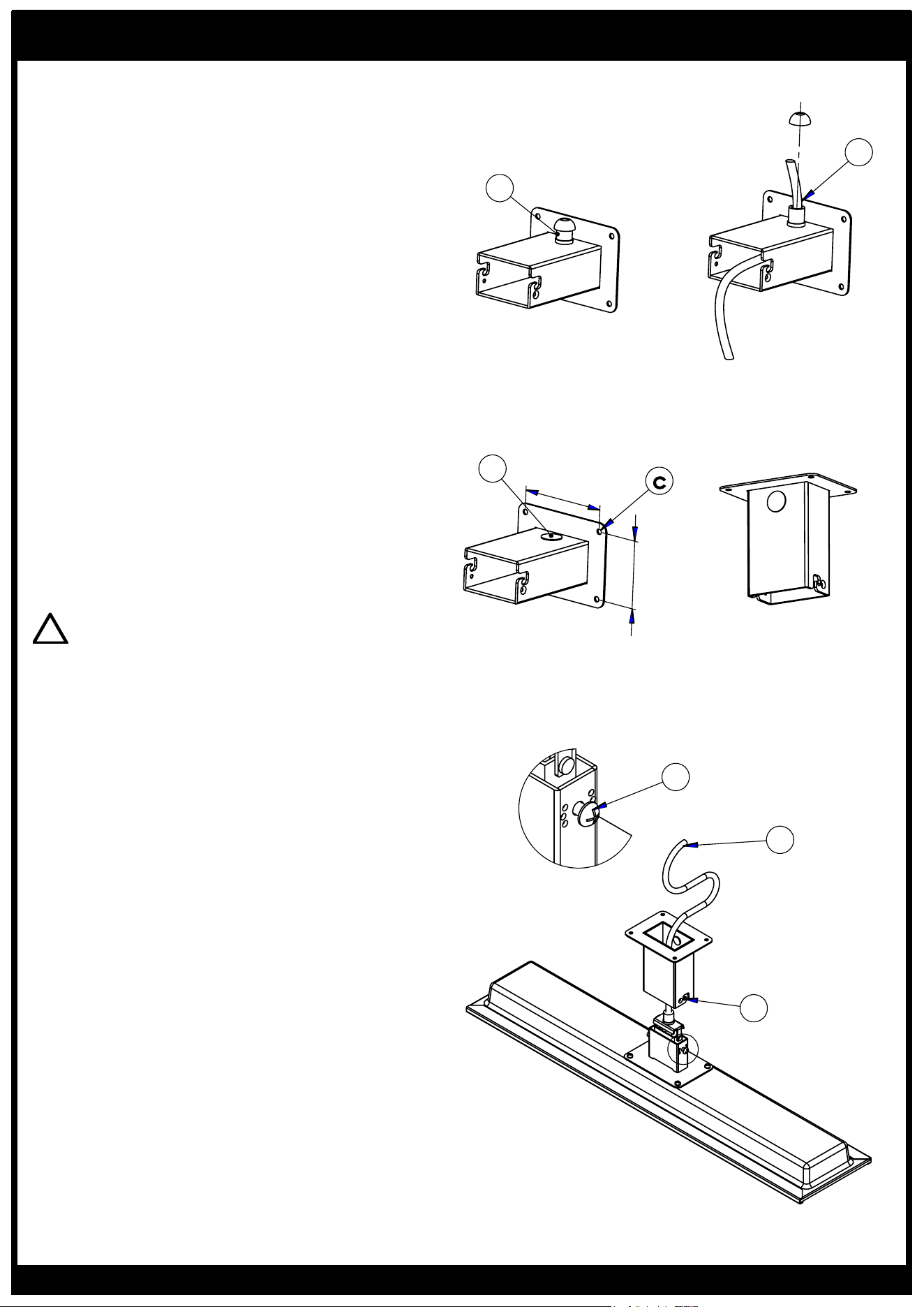
To exit the cable through the side of the wall
mounting bracket, start from step 1.
1. Unscrew and remove plug-in wall bracket (a).
2. Attach extra supplied cable gland into the same
hole from the outside of the bracket. Fasten in
place
with the metal cable gland nut from inside the
bracket
(b).
NOTE: Continue to step 3 below
OPTION 2
To exit the cable through the wall bracket directly
into your ceiling or wall cavity, start from step 3.
3. Attach mounting bracket to ceiling or wall using
fasteners appropriate for the surface (c). Ensure
the bracket is firmly secured with fasteners in all
4 holes before proceeding. For wall mounting ,
ensure the silver plug or cable gland (a) is facing
upwards.
!
WARNING: The bracket mounting surface
MUST be protected from rain. This is necessary
to stop water entering the bracket & maintain
IPX4rating.
4. Ensure M6x14mm screws are inserted into both
sides of heater bracket with 6mm of the threaded
shaft exposed under the screw head (d).
5. For cable exit through the side of the wall
bracket: feed heater power cable through cable
gland in wall bracket (e).
NOTE: This is easier when the top of the cable
gland is
completely removed when feeding the cable
through the bracket. The cap can then be inserted
onto the cable for fastening.
6. For cable exit into the ceiling or wall cavity:
make a small hole in the black foam on the bracket
mounting surface to pass the cable through. Make
electrical connection now or feed cable into wall
or ceiling for subsequent connection (f). This is
described under ‘Electrical Installation’ on page 11.
7. Insert heater bracket into mounting bracket by
hooking M6 screws into place in mounting slots
(g).
f
g
110
80
c
a
e
b
d
Wall mount
Ceiling mount
Cable exit into wall cavity
Optional: Cable exit through wall
bracket
Loading ...
Loading ...
Loading ...