
X7508230800
©11/21 ECHO Incorporated
Operator’s
Manual
DPAS-2600SB
Pro Attachment
Series™
Read and understand all provided literature before use. Failure
to do so could result in serious injury.
Cancer and Reproductive Harm
www.P65Warnings.ca.gov
Note: This product complies with CAN ICES-003(B) / NMB-003(B)

TABLE OF CONTENTS DPAS-2600SB
2 X7508230800
©11/21 ECHO Incorporated
TABLE OF CONTENTS
Introduction ................................................................................................. 3
Servicing Information .................................................................................. 4
Parts and Serial Number...................................................................... 4
Service................................................................................................. 4
ECHO Consumer Product Support ...................................................... 4
Product Registration ............................................................................ 4
Additional Literature............................................................................. 4
Safety.......................................................................................................... 5
Manual Safety Symbols and Important Information ............................. 5
International Symbols .......................................................................... 6
Handling the Product .......................................................................... 7
Equipment.......................................................................................... 13
Description ................................................................................................ 15
Assembly................................................................................................... 17
Support Handle Installation................................................................ 17
Power Head Shaft to Lower Shaft Assembly ..................................... 17
Balance and Adjust Unit..................................................................... 22
Operation .................................................................................................. 23
Operation with Blades........................................................................ 23
Blade Selection.................................................................................. 24
Starting The Unit ................................................................................ 26
Stopping Unit ..................................................................................... 27
Applications ....................................................................................... 27
Operating Techniques - Nylon Line Head .......................................... 27
Operating Techniques - Metal or Plastic Blade .................................. 28
Reaction Forces................................................................................. 29
Blade Cutting Problems ..................................................................... 31
Maintenance ............................................................................................. 32
Skill Levels ......................................................................................... 32
Maintenance Intervals........................................................................ 33
Maintenance and Care ...................................................................... 34
Lubrication ......................................................................................... 35
Nylon Line Replacement.................................................................... 36
Sharpening Metal Blades................................................................... 38
Troubleshooting ........................................................................................ 40
Storage ..................................................................................................... 41
Storage ............................................................................................. 41
Disposal ............................................................................................. 42
Specifications............................................................................................ 43
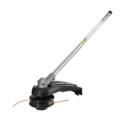
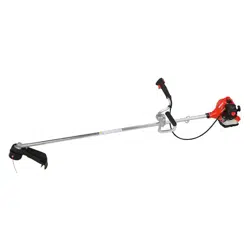
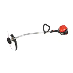
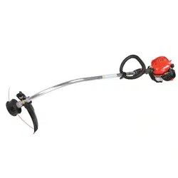
ECHO Optional Attachments ............................................................. 44
Warranty.................................................................................................... 45
Product Registration ..................................................................................46
DPAS-2600SB INTRODUCTION
X7508230800 3
©11/21 ECHO Incorporated
INTRODUCTION
Specifications, descriptions, and illustrative material in this literature are as
accurate as possible. Specifications are subject to change without notice.
Illustrations might include optional equipment and accessories, and might
not include all standard equipment. Your equipment might appear slightly
different than pictured equipment.
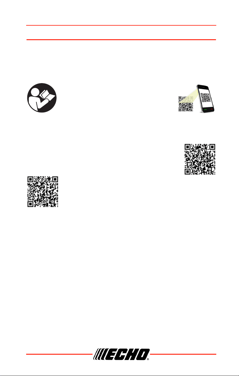
Read and understand all provided literature.
Literature contains specifications and
information for safety, operation,
maintenance, storage, and assembly
specific to this product. Scan QR codes for
more information.
For additional literature, including safety manuals where applicable, or
questions regarding terms used in this manual, visit:
https://www.echo-usa.com/manuals
OR
https://www.shindaiwa-usa.com/manuals
SERVICING INFORMATION DPAS-2600SB
4 X7508230800
©11/21 ECHO Incorporated
SERVICING INFORMATION
Parts and Serial Number
Genuine ECHO parts and
assemblies for your ECHO products
are available only from an
Authorized ECHO Dealer. When
you do need to buy parts always
have the model number and serial
number of the unit with you. For
future reference write them in the
space provided below.
Model No. _____________________ Serial No. ____________________
Service
Service of this product during the warranty period must be performed by an
Authorized ECHO Service Dealer. For the name and address of the
Authorized ECHO Service Dealer nearest you, ask your retailer or call:
1-800-432-ECHO (3246). Dealer information is also available on our Web
Site www.echo-usa.com. When presenting your unit for Warranty service/
repairs, proof of purchase is required.
ECHO Consumer Product Support
If you require assistance or have questions concerning the application,
operation, or maintenance of this product, call the ECHO Consumer
Product Support Department at 1-800-432-ECHO (3246) from 8:00 a.m. to
5:00 p.m. (Central Standard Time) Monday through Friday. Before calling,
please know the model and serial number of your unit.
Product Registration
Register your ECHO equipment online at www.echo-usa.com or by filling
out the product registration sheet included in this manual. Registering your
product confirms warranty coverage and provides a direct link to ECHO if
we find it necessary to contact you.
Additional Literature
In addition to finding information online, information is available from your
Authorized ECHO Service Dealer, or by contacting ECHO Incorporated,
400 Oakwood Road, Lake Zurich, IL 60047, 1-800-432-ECHO (3246).
DPAS-2600SB SAFETY
X7508230800 5
©11/21 ECHO Incorporated
SAFETY
Manual Safety Symbols and Important Information
Throughout this manual and on the product itself, you will find safety alerts
and helpful, informational messages preceded by symbols or key words.
The following is an explanation of those symbols and key words and what
they mean to you.
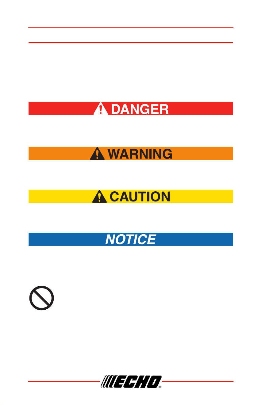
The safety alert symbol accompanied by the word “DANGER”
calls attention to an act or condition which WILL lead to serious
personal injury or death if not avoided.
The safety alert symbol accompanied by the word “WARNING”
calls attention to an act or condition which CAN lead to serious
personal injury or death if not avoided.
The safety alert symbol accompanied by the word “CAUTION”
calls attention to an act or condition which might lead to minor
or moderate personal injury if not avoided.
The enclosed message provides information necessary for the
protection of the unit.
Note: This enclosed message provides tips for use, care and
maintenance of the unit.
CIRCLE AND SLASH SYMBOL
This symbol means the specific action shown is prohibited.
Ignoring these prohibitions can result in serious or fatal injury.
SAFETY DPAS-2600SB
6 X7508230800
©11/21 ECHO Incorporated
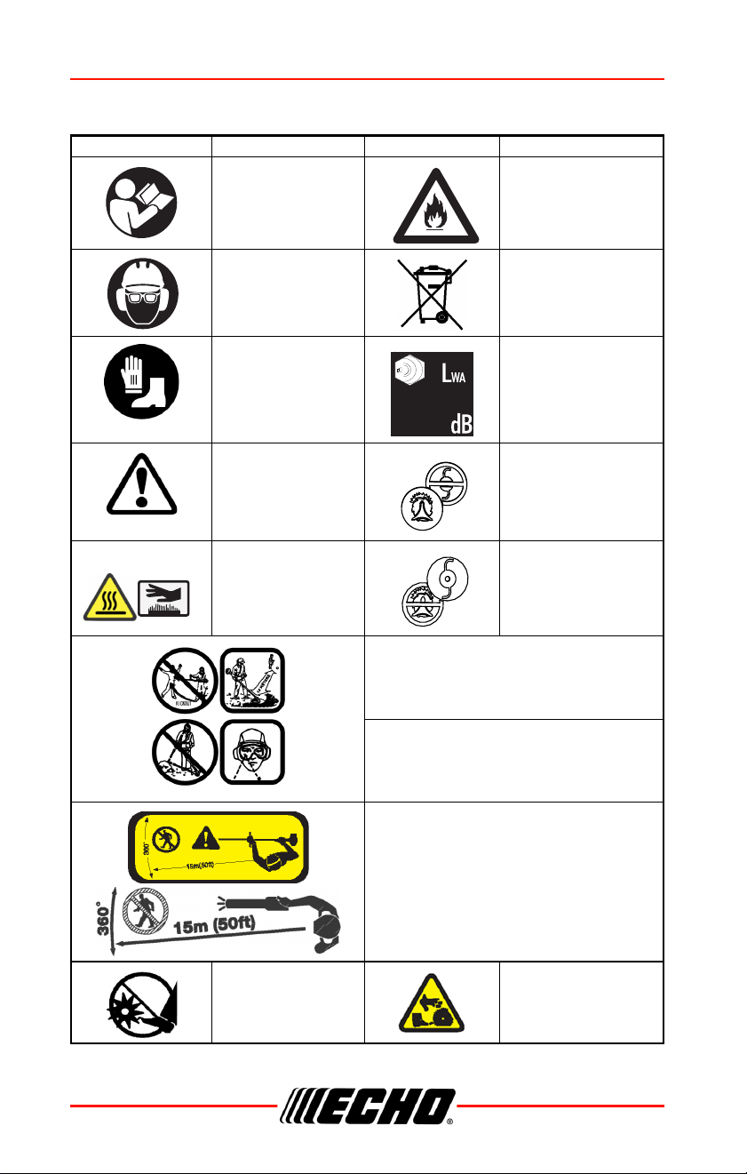
International Symbols
Symbol Description Symbol Description
Warning, See
Operator’s Manual
Beware of Fire
Wear Eye, Ear and
Head Protection
Do Not Dispose in
Household Trash
Wear Hand and Foot
Protection
Guaranteed Sound
Power Level
Safety / Alert
DO NOT USE Line Head
- Blades Only
Hot Surface
DO NOT USE BLADES -
Line Head Only
AVOID KICKOUT
Keep Bystanders At Least
15 m (50 ft.) Away
Beware Thrown Objects
Wear Eye Protection
Keep Bystanders and Helpers
Away 15 m (50 ft.)
Keep Feet Away
From Blade
Rotating Cutting
Attachment
DPAS-2600SB SAFETY
X7508230800 7
©11/21 ECHO Incorporated
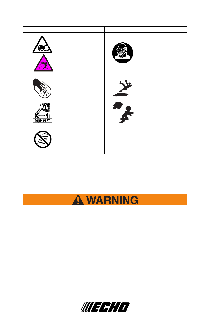
Note: Not all symbols will appear on your unit.
Handling the Product
General Power Tool Safety Warnings
Read all safety warnings and all instructions and specifications
provided with this power tool. Failure to follow the warnings and
instructions may result in electric shock, fire and/or serious
injury.
Save all warnings and instructions for future reference.
The term "power tool" in the warnings refers to your mains-operated
(corded) power tool or battery-operated (cordless) power tool.
Work Area Safety
• Keep work area clean and well lit. Cluttered or dark areas invite
accidents.
Thrown Objects Wear Face Shield
Finger Severing
Wear Slip Resistant
Footwear
Do not operate closer
than 15 m (50 ft.) from
electrical hazards.
Keep bystanders at
least 15 m (50 ft.) away.
Plan a retreat path from
falling objects.
Do not expose
to rain / water
Symbol Description Symbol Description

SAFETY DPAS-2600SB
8 X7508230800
©11/21 ECHO Incorporated
• Do not operate power tools in explosive atmospheres, such as in the
presence of flammable liquids, gases or dust. Power tools create sparks
which may ignite the dust or fumes.
• Keep children and bystanders away while operating a power tool.
Distractions can cause you to lose control.
Electrical Safety
• Power tool plugs must match the outlet. Never modify the plug in any way.
Do not use any adapter plugs with earthed (grounded) power tools.
Unmodified plugs and matching outlets will reduce the risk of electric
shock.
• Avoid body contact with earthed or grounded surfaces such as pipes,
radiators, ranges and refrigerators. There is an increased risk of electric
shock if your body is earthed or grounded.
• Do not expose power tools to rain or wet conditions. Water entering a
power tool will increase the risk of electric shock.
• Do not abuse the cord. Never use the cord for carrying, pulling or
unplugging the power tool. Keep cord away from heat, oil, sharp edges or
moving parts. Damaged or entangled cords increase the risk of electric
shock.
• When operating a power tool outdoors, use an extension cord suitable for
outdoor use. Use of a cord suitable for outdoor use reduces the risk of
electric shock.
• If operating a power tool in a damp location is unavoidable, use a ground
fault circuit interrupter (GFCI) protected supply. Use of a GFCI reduces
the risk of electric shock.
Personal Safety
• Stay alert, watch what you are doing and use common sense when
operating a power tool. Do not use a power tool while you are tired, ill, or
under the influence of drugs, alcohol or medication. A moment of
inattention while operating power tools may result in serious personal
injury.
• Use personal protective equipment. Always wear eye protection.
Protective equipment such as dust mask, non-skid safety shoes, hard
hat, or hearing protection used for appropriate conditions will reduce
personal injuries.
• Prevent unintentional starting. Ensure the switch is in the off-position
before connecting to power source and/or battery, picking up or carrying
the tool. Carrying power tools with your finger on the switch or energizing
power tools that have the switch on invites accidents.

DPAS-2600SB SAFETY
X7508230800 9
©11/21 ECHO Incorporated
• Remove any adjusting key or wrench before turning the power tool on. A
wrench or a key left attached to a rotating part of the power tool may
result in personal injury.
• Do not overreach. Keep proper footing and balance at all times. This
enables better control of the power tool in unexpected situations.
• Dress properly. Do not wear loose clothing or jewelry. Keep your hair,
clothing and gloves away from moving parts. Loose clothes, jewelry or
long hair can be caught in moving parts.
• If devices are provided for the connection of dust extraction and collection
facilities, ensure these are connected and properly used. Use of dust
collection can reduce dust-related hazards.
• Do not let familiarity gained from frequent use of tools allow you to
become complacent and ignore tool safety principles. A careless action
can cause severe injury within a fraction of a second.
Proper Clothing
Wear snug-fitting, durable clothing:
• Pants should have long legs, shirts should have long sleeves.
• DO NOT WEAR SHORTS.
• DO NOT WEAR TIES, SCARVES, JEWELRY, or clothing with loose or
hanging items that could become entangled in moving parts or
surrounding growth.
• Keep clothing buttoned or zipped, and keep shirt tails tucked in.
• Wear sturdy work shoes with nonskid rubber soles.
• DO NOT WEAR OPEN TOED SHOES.
• DO NOT OPERATE UNIT WITH BARE FEET.
Power Tool Use and Care
• Do not force the power tool. Use the correct power tool for your
application. The correct power tool will do the job better and safer at the
rate for which it was designed.
• Do not use the power tool if the switch does not turn it on and off. Any
power tool that cannot be controlled with the switch is dangerous and
must be repaired.
• Disconnect the plug from the power source and/or the battery from the
power tool before making any adjustments, changing accessories, or
storing power tools. Such preventive safety measures reduce the risk of
starting the power tool accidentally.

SAFETY DPAS-2600SB
10 X7508230800
©11/21 ECHO Incorporated
• Store idle power tools out of the reach of children and do not allow
persons unfamiliar with the power tool or these instructions to operate the
power tool. Power tools are dangerous in the hands of untrained users.
• Maintain power tools and accessories. Check for misalignment or binding
of moving parts, breakage of parts and any other condition that may affect
the power tool’s operation. If damaged, have the power tool repaired
before use. Many accidents are caused by poorly maintained power tools.
• Keep cutting tools sharp and clean. Properly maintained cutting tools with
sharp cutting edges are less likely to bind and are easier to control.
• Use the power tool, accessories and tool bits etc. in accordance with
these instructions, taking into account the working conditions and the
work to be performed. Use of the power tool for operations different from
those intended could result in a hazardous situation.
• Keep handles and grasping surfaces dry, clean, and free from oil and
grease. Slippery handles and grasping surfaces do not allow for safe
handling and control of the tool in unexpected situations.
Battery Tool Use and Care
• Recharge only with ECHO eFORCE™ 56V battery series chargers. A
charger that is suitable for one type of battery may create a risk of fire
when used with another battery.
• Use only with ECHO eFORCE™ 56V battery series. Use of any other
battery may create a risk of injury and fire.
• When battery is not in use, keep it away from other metal objects, like
paper clips, coins, keys, nails, screws or other small metal objects, that
can make a connection from one terminal to another. Shorting the battery
terminals together may cause burns or a fire.
• Under abusive conditions, liquid may be ejected from the battery; avoid
contact. If contact accidentally occurs, flush with water. If liquid contacts
eyes, additionally seek medical help. Liquid ejected from the battery may
cause irritation or burns.
• Do not open or destroy the battery. Electrolytes contained within the
battery are corrosive and may cause damage to eyes or skin if released.
It may be toxic if swallowed.
• Exercise care in handling batteries to avoid shorting the battery with
conducting materials such as rings, bracelets, keys, etc. The battery or
conductor may overheat and cause burns if contact with said materials is
made.
• Do not use a battery or tool that is damaged or modified. Damaged or
modified batteries may exhibit unpredictable behavior resulting in fire,
explosion or risk of injury.
DPAS-2600SB SAFETY
X7508230800 11
©11/21 ECHO Incorporated
• Do not expose a battery or tool to fire or excessive temperature.
Exposure to fire or temperature above 130°C (266°F) may cause
explosion.
• Follow all charging instructions and do not charge the battery or tool
outside the temperature range specified in the instructions. Charging
improperly or at temperatures outside the specified range may damage
the battery and increase the risk of fire.
Service
• Have your power tool serviced by a qualified repair person using only
identical replacement parts. This will ensure that the safety of the power
tool is maintained.
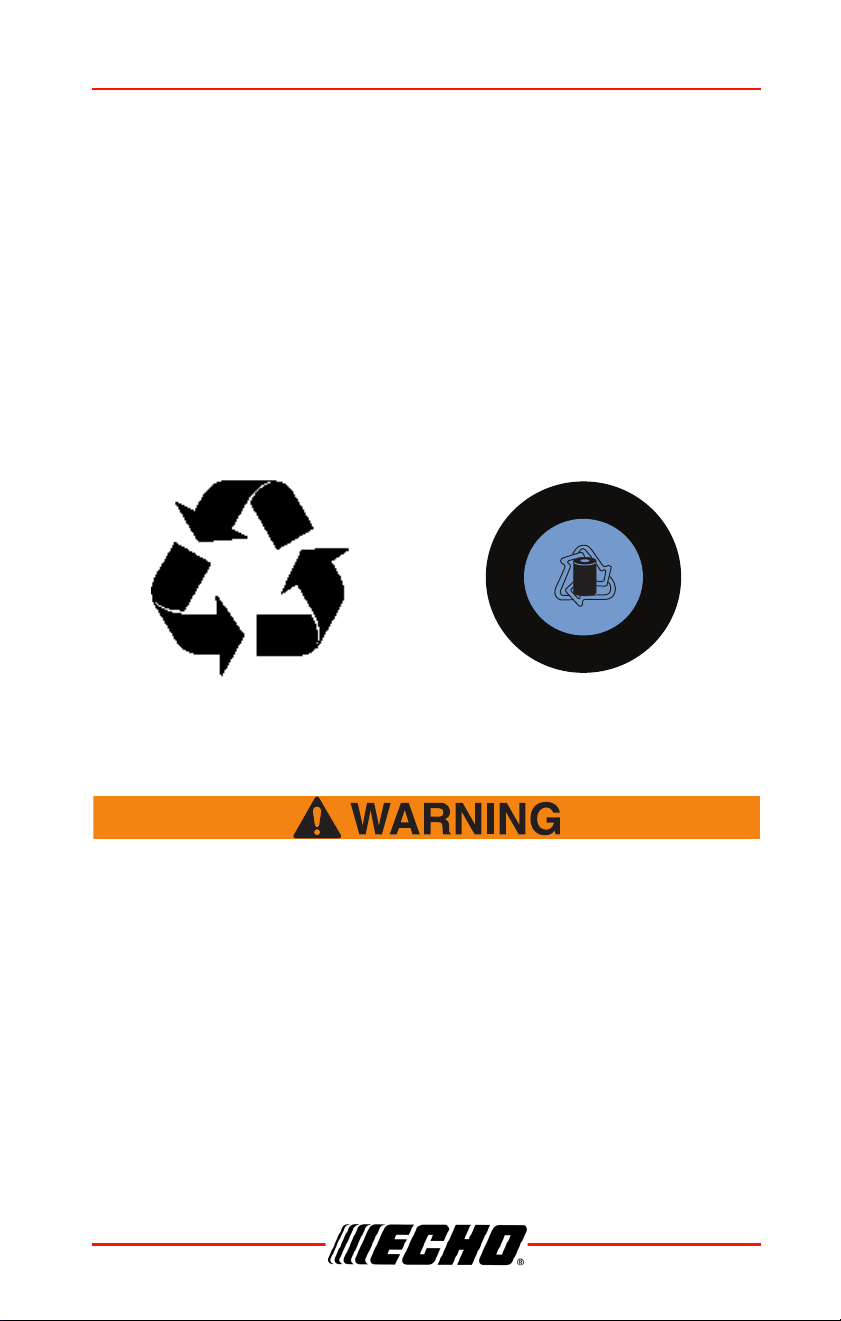
Environmentally Safe Battery Disposal
The toxic and corrosive materials below are in the batteries used in this
machine: Lithium-Ion, a toxic material.
Discard all toxic materials in a specified manner to prevent
contamination of the environment. Before discarding a
damaged or worn out Lithium-ion battery, contact your local
waste disposal agency, or the local Environmental Protection
Agency for information and specific instructions. Take the
batteries to a local recycling and/or disposal center, certified for
Lithium-ion disposal.
R
E
C
Y
C
L
E
1
.
8
0
0
.
8
2
2
.
8
8
3
R B R C
Li - ion
TM

SAFETY DPAS-2600SB
12 X7508230800
©11/21 ECHO Incorporated
If the battery cracks or breaks, with or without leaks, do not
recharge it and do not use. Discard it and replace with a new
battery. DO NOT TRY TO REPAIR IT! To prevent injury and risk
of fire, explosion, or electric shock, and to avoid damage to
the environment:
• Cover the terminals of the battery with heavy-duty adhesive tape.
• DO NOT try to remove or destroy any of the battery components.
• DO NOT try to open the battery.
• If a leak develops, the released electrolytes are corrosive and toxic. DO
NOT get the solution in the eyes or on skin, and do not swallow it.
• DO NOT put these batteries in your regular household trash.
• DO NOT incinerate.
• DO NOT put them where they will become part of any waste landfill or
municipal solid waste stream.
• Take them to a certified recycling or disposal center.
This equipment has been tested and found to comply with the limits
for a Class B digital device, pursuant to Part 15 of the FCC Rules.
These limits are designed to provide reasonable protection against
harmful interference in a residential installation. This equipment
generates, uses and can radiate radio frequency energy, and if not
installed and used in accordance with the instructions, may cause
harmful interference to radio or television reception. The reception
can be determined by turning the equipment off and on. The user is
encouraged to try to correct the interference by one or more of the
following measures:
• Reorient or relocate the receiving antenna.
• Increase the separation between the equipment and the receiver.
• Connect the equipment into an outlet on a circuit different from that to
which the receiver is connected.
• Consult the dealer or an experienced radio/TV technician for help.

DPAS-2600SB SAFETY
X7508230800 13
©11/21 ECHO Incorporated
Read the Manuals
• Provide all users of this equipment with the operator’s manual for
instructions on safe operation.
Clear the Work Area
• Always clear the work area of foreign objects such as rocks, broken
glass, nails, wire, or string, which can be thrown or become entangled in
the cutting attachment, and check for any hidden hazards. Spectators and
fellow workers must be warned, and children and animals prevented from
coming nearer than 50 ft. (15 m) while the unit is in use.
• Outside the 50 ft. (15 m) zone, there is still a risk of injury from thrown
objects.
• Bystanders should be encouraged to wear eye protection.
• If you are approached, stop the unit and cutting attachment.
• When a bladed unit is used, there is the added risk of injury to bystanders
being struck with the moving blade in the event of a blade thrust or other
unexpected reaction of the blade.
Keep a Firm Grip
• Always hold throttle handle and support handle with thumbs and fingers
tightly encircling the handles.
Keep a Solid Stance
• Maintain footing and balance at all times. Do not stand on slippery,
uneven or unstable surfaces. Do not work in odd positions or on ladders.
Do not overreach.
Equipment
Use only ECHO attachments. Serious injury may result from the
use of a non-approved attachment combination. ECHO
Incorporated will not be responsible for the failure of cutting
devices, attachments or accessories which have not been
tested and approved by ECHO. Read and comply with all safety
instructions.
◆ Do not attempt to modify this product. Serious injury can
result from the use of any modified product.
◆ Check unit for loose or missing nuts, bolts, and screws.
Tighten or replace as needed.

SAFETY DPAS-2600SB
14 X7508230800
©11/21 ECHO Incorporated
◆ Inspect shield for damage and ensure that shield is
properly installed, and that the cutoff knife is securely in
place. Replace if either is damaged or missing.
◆ Check that the cutting attachment is firmly attached and in
safe operating condition.
◆ Manufacturer recommended flexible non-metallic line is
installed in the trimmer head.
◆ Assure that trigger switch, trigger switch lockout, and stop
switch all work properly.
◆ Check that handle and harness (if included) are installed
and adjusted for safe, comfortable operation. See
Assembly Section for proper adjustment.
Moving parts can amputate fingers or cause severe injuries.
Keep hands, clothing and loose objects away from all openings.
◆ ALWAYS stop unit and make sure all moving parts have
come to a complete stop before assembling unit, removing
obstructions, clearing debris, or servicing unit.
◆ DO NOT start or operate unit unless all guards and
protective covers are properly assembled to unit.
◆ NEVER reach into any opening while the unit is running.
Moving parts may not be visible through openings.
◆ Position wiring safely to prevent snagging, separation of
connectors, or breakage during operation. Gather excess
wire, and secure with wiring clamp if provided on
equipment.
◆ Check wiring and connectors for nicks, cuts, exposed wire,
or other damage, and repair or replace as needed. Exposed
wire or connectors can cause shocks, sparks, and risk of
fire or explosion, resulting in serious injury.
◆ Check wire terminals for secure connections.
DPAS-2600SB DESCRIPTION
X7508230800 15
©11/21 ECHO Incorporated
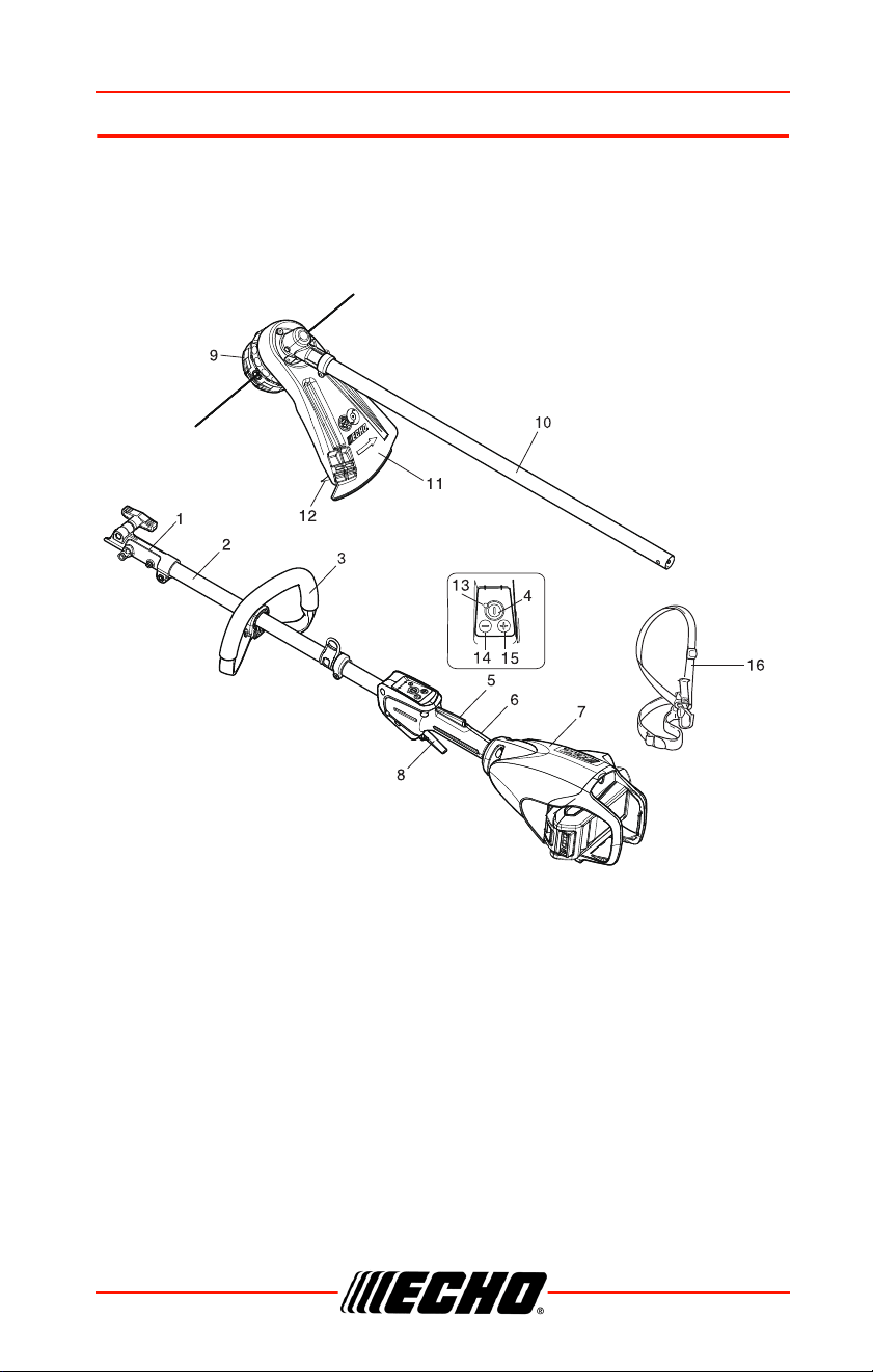
DESCRIPTION
Locate the safety decal(s) on your unit. Make sure the decal(s) is legible
and that you understand and follow the instructions on it. If a decal cannot
be read, a new one can be ordered from your ECHO dealer. Safety label is
for example only. Your label my appear slightly different.
1. Drive Shaft Coupler
2. Upper Drive Shaft Assembly
3. Support Handle - For Left Hand
4. Power Button
5. Trigger Switch Lockout
6. Throttle Handle - For Right Hand
7. Power Head
8. Throttle Trigger
9. Nylon Cutting Attachment

DESCRIPTION DPAS-2600SB
16 X7508230800
©11/21 ECHO Incorporated
10. Lower Drive Shaft Assembly
11. Debris Shield With Cutoff Knife
12. Cutoff Knife
13. Power Indicator LED
14. - Button
15. + Button
16. Shoulder Harness
DPAS-2600SB ASSEMBLY
X7508230800 17
©11/21 ECHO Incorporated
ASSEMBLY
Support Handle Installation
Note: Label shows minimum
spacing for support
handle location.
1. If necessary, position support
handle for comfortable
operation and securely tighten
screws.
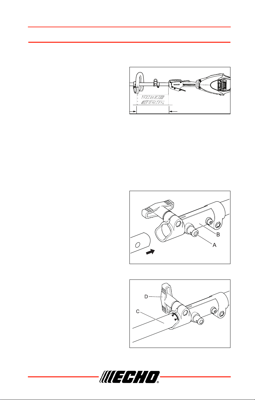
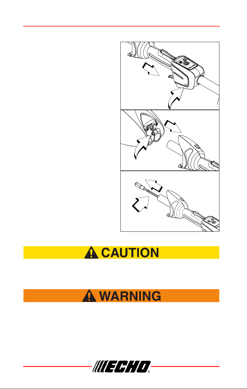
Power Head Shaft to Lower Shaft Assembly
1. Set Power Head/Shaft Assembly on a level surface.
2. Pull locater pin (A) out, and turn counterclockwise one-quarter turn to
lock-out position.
3. Remove storage hook and cap from attachment drive shaft.
Note: Your coupler may appear different than coupler shown.
Earlier model power heads may have shorter couplings.
4. Carefully fit attachment drive
shaft assembly into coupler (B).
Rotate shaft (C) to make sure
inner lower drive shaft engages
square upper drive shaft
socket.
Note: Lower bearing housing
and head assembly must
be in line with power
head.
Note: Some models have an
assembly line decal to assist in assembly.
5. Rotate locater pin (A) one-
quarter turn clockwise to
engage lower shaft hole. Make
sure locater pin is fully engaged
by rotating lower drive shaft.
Locater pin should snap flush in
coupler. Full engagement will
prevent further shaft rotation.
6. Secure lower shaft assembly to
coupler by tightening clamping
knob (D).

ASSEMBLY DPAS-2600SB
18 X7508230800
©11/21 ECHO Incorporated
Battery Charging
Note: See separate operator’s manuals packaged with battery and
charger.
• Use only with ECHO eFORCE™ 56V battery series batteries and
chargers.
• Keep charger and battery away from damp conditions and all liquids.
• Do not operate the charger on an easily combustible surface (e.g. paper,
textiles) or in an environment with a high risk of fire.
• Do not cover the charger. Covering the charger will prevent it from
cooling.
• Do not operate the charger in explosive atmospheres, such as in the
presence of flammable liquids, gases or dust. Charger can produce
sparks which may ignite the dust or fumes - there is a risk of explosion.
• Connect the charger only to the mains of voltage and frequency specified
on the rating plate.
• Connect the charger only to an easily accessible wall outlet.
• Never insert objects in the battery's or charger's cooling slots.
• Do not charge or use a defective, damaged or deformed battery and
charger.
• Do not open, damage or drop the battery or the charger.
• Fluid may leak from the battery if it is damaged or not used properly;
avoid contact with the skin. In the event of accidental contact, wash the
affected areas of the skin with plenty of water and soap. If fluid gets in the
eyes, do not rub. Rinse the eyes with plenty of water for at least 15
minutes. Also seek medical assistance.
• Never bridge (short circuit) the battery contacts or the charger's terminals
with metallic objects.
• Protect from direct sunlight, heat and open flames and never throw
battery into fire; there is a risk of explosion.
DPAS-2600SB ASSEMBLY
X7508230800 19
©11/21 ECHO Incorporated
• In the event of smoke or fire in the charger, disconnect it from the wall
outlet immediately.
• If the connecting cord is damaged, immediately disconnect the plug from
the power supply to avoid the risk of electric shock.
• Do not expose battery to microwaves or high pressure.
• To reduce the risk of stumbling, position and mark the connecting cord in
such a way that it cannot be damaged or endanger others.
The battery comes partially charged from the factory and needs to be
fully charged before first use. Charge the battery when it no longer
produces sufficient power to operate the unit or when battery lights
indicate that the battery is low.
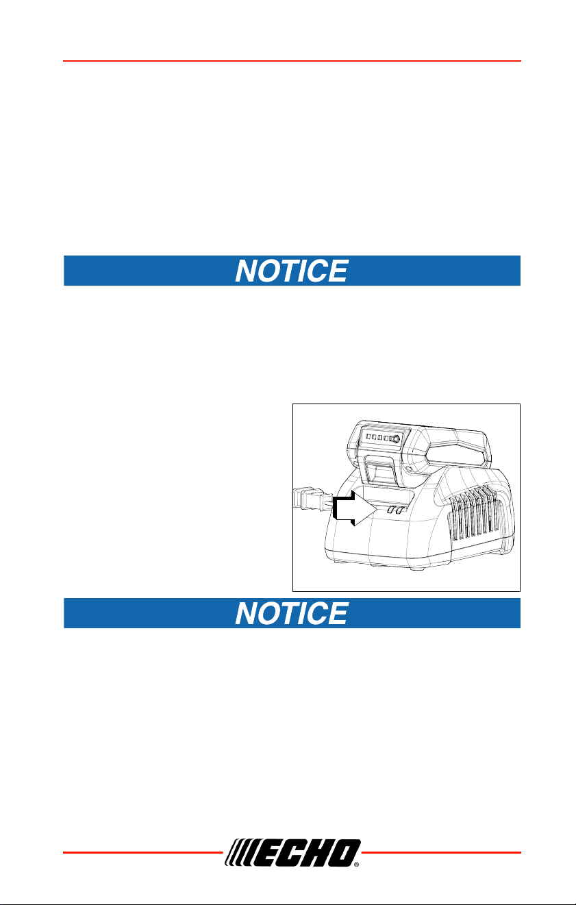
1. Plug charger AC cord in the
wall outlet.
2. Align ridges on battery with
grooves on charger, and slide
battery into charger.
3. During normal charging, the
charger LED (A) will blink
GREEN.
If charger detects a problem, LED will blink RED. Remove battery
from charger, clear obstructions from contacts and reinstall battery
into charger. If battery is outside acceptable temperature range (0°C
to 60°C, 32°F to 140°F) LED will remain RED.
A

ASSEMBLY DPAS-2600SB
20 X7508230800
©11/21 ECHO Incorporated
4. When charging is complete,
LED will remain GREEN. See
battery manual for charging
time.
5. Verify battery is fully charged.
Remove battery from charger,
press battery charge status
button (B), and check LED
display.
• One green light indicates that
the battery has 0-25% charge.
• Two green lights indicate that
the battery has 25-50% charge.
• Three green lights indicate that the battery has 50-75% charge.
• Four green lights indicate that the battery has 75-100% charge.
6. Unplug charger AC cord from the wall outlet.
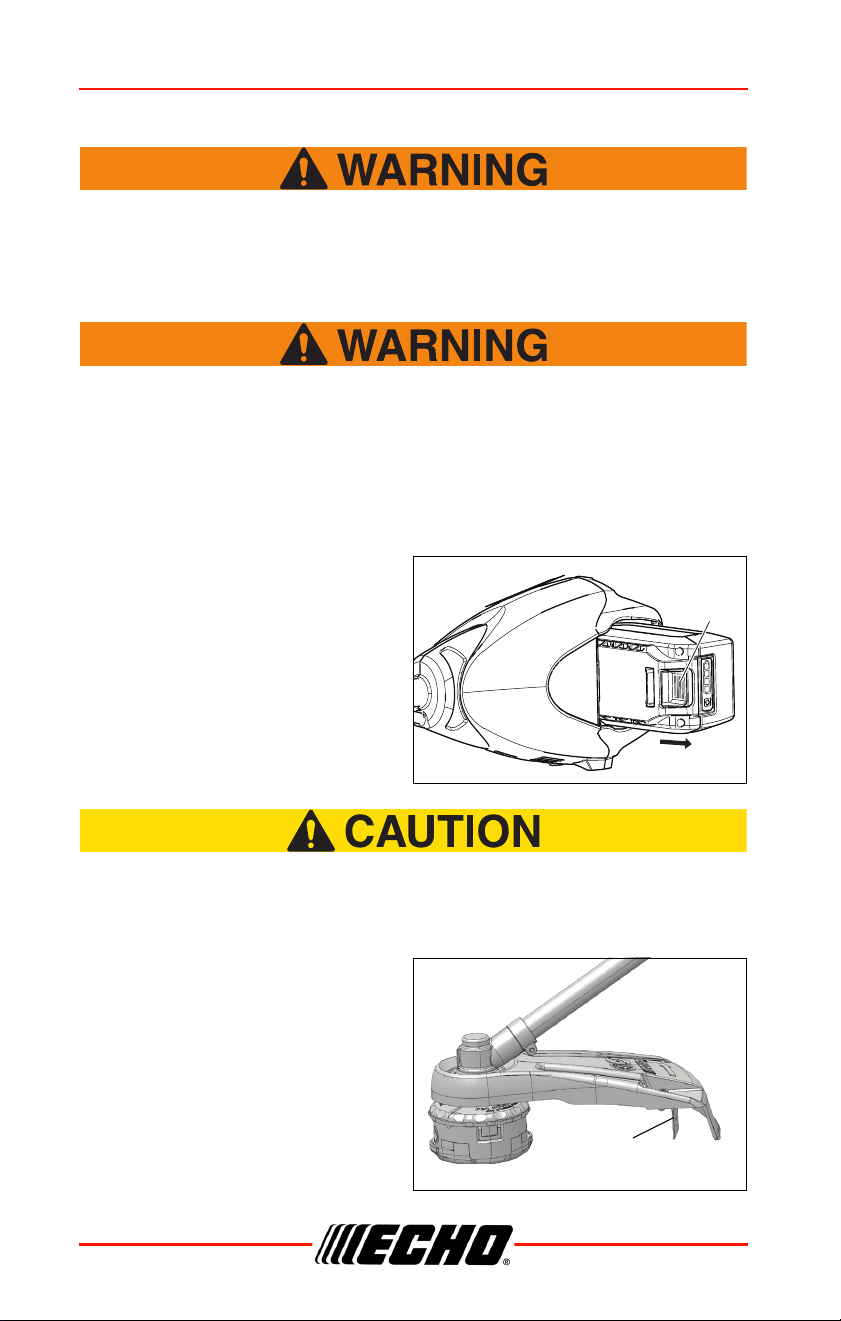
Installing the Battery
The attachment will operate when the battery is installed, the
power indicator LED is lit, and the trigger switch and trigger
switch lockout are engaged. Make sure the unit is properly
positioned to prevent loss of control and possible serious
injury. Keep movable parts of the attachment off the ground and
away from objects that could become entangled or thrown.
Note: The battery comes partially charged from the factory and
needs to be fully charged before first use.
B
DPAS-2600SB ASSEMBLY
X7508230800 21
©11/21 ECHO Incorporated
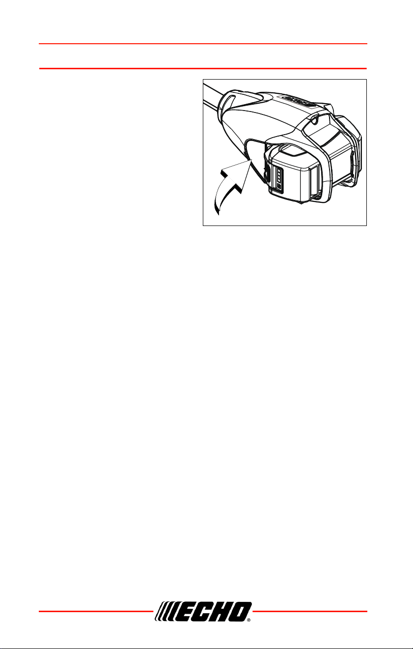
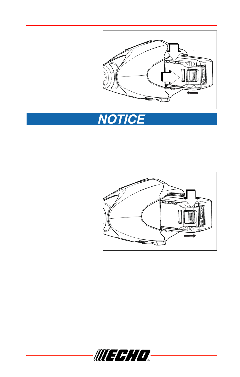
1. Make sure power to unit
is turned off.
2. Align ridges (A) on
battery with grooves in
power head. Slide
battery into power head.
3. Assure the battery latch
(B) snaps into place and
battery is secure before
beginning operation.
Assure battery latch is fully engaged before using unit.
Removing the Battery
To remove battery, depress
battery latch release (C)
slide battery out of power
head.
A
B
C
ASSEMBLY DPAS-2600SB
22 X7508230800
©11/21 ECHO Incorporated
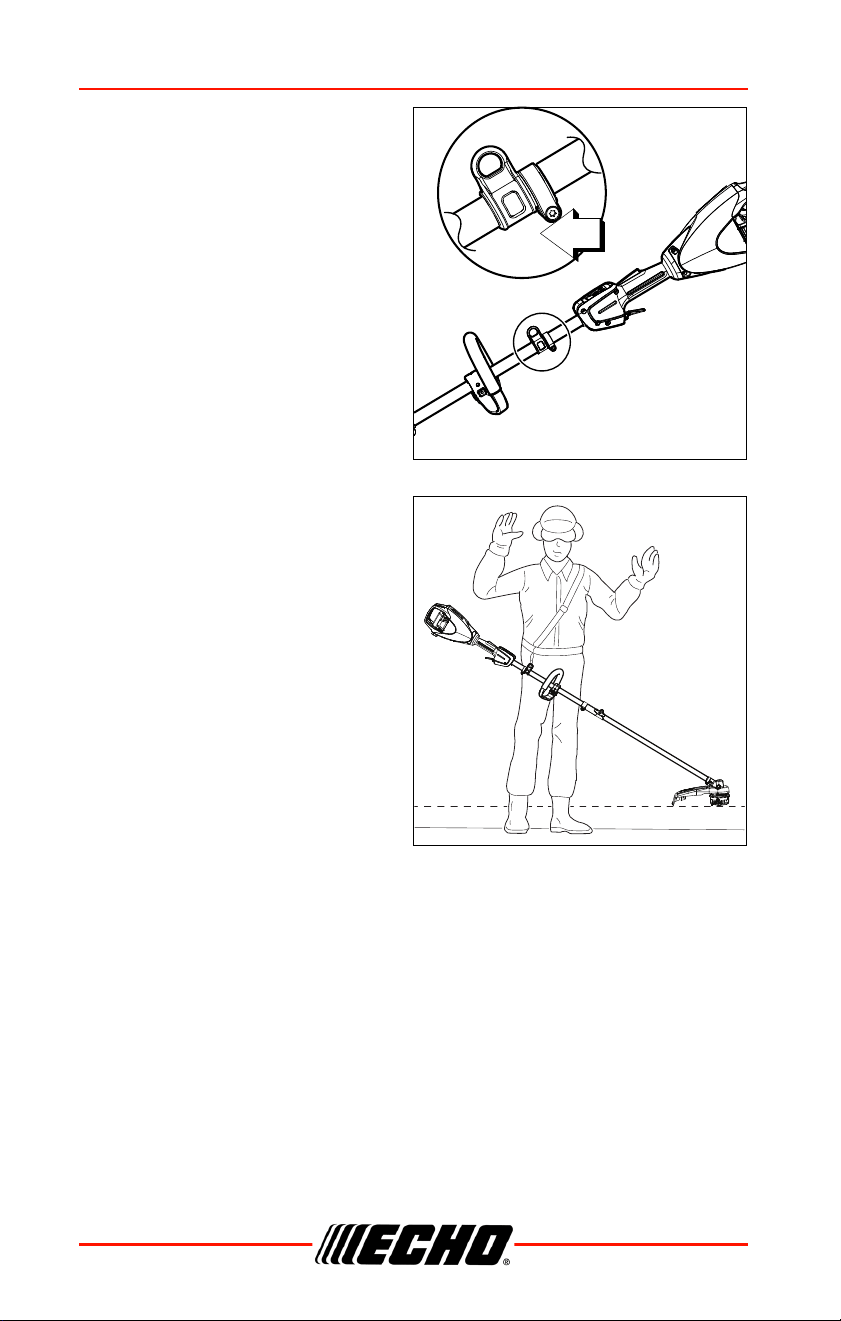
Balance and Adjust Unit
1. Loosen harness ring clamp
screw (A).
2. Put on harness and attach unit
to harness.
3. Slide harness clamp up or down
until unit balances with head or
blade 200 mm ± 100 mm
(8 in ± 4 in) from the ground.
4. Tighten harness clamp screw.
5. Loosen handle clamp screw(s),
and position handle for
comfortable operation.
6. Tighten handle clamp screws
securely.
A
DPAS-2600SB OPERATION
X7508230800 23
©11/21 ECHO Incorporated
OPERATION
Operation with Blades
Metal blades are very sharp and can cause severe injuries, even
if unit is off and blades are not moving. Avoid contact with
blades. Wear gloves to protect hands.
Blade use demands specific brushcutter configuration.
Operation without specified shield, barrier bar or U-handle, and
harness can result in serious personal injury. Follow installation
instructions.
*ANSI standards require brushcutters be equipped with a barrier bar or
restrictive harness. U-Handle ensures a higher safety factor.
Do Not install blades on GT (Curved Shaft) model trimmers.
• Use only ECHO approved parts. Failure to use the correct parts can
cause the blade to fly off. Serious injury to the operator and / or
bystanders can occur.
Pro Maxi-Cut
Grass / Weed
Blade
Tri-Cut Grass
/ Weed Blade
Metal Grass /
Weed Blade
Metal Brush /
Clearing
Blades
Support
Handle, with or
without Barrier
Bar
U-Handle or Support Handle
with Barrier Bar
U-handle*
Shield with
cutoff knife
Shield without cutoff knife
Harness Harness
Upper Plate /
Flat Washer
Upper / Lower Blade Plates
Hex Nut Hex Nut
New Cotter Pin New Cotter Pin

OPERATION DPAS-2600SB
24 X7508230800
©11/21 ECHO Incorporated
• Arbor diameter of upper blade plate must match arbor diameter of blades.
• For barrier bar or U-handle, follow instructions supplied with either blade
conversion kit or U-handle kit, and verify blade is secured properly.
• A new cotter pin is required each time a blade is installed.
• Shoulder harnesses may be used on all trimmers and brushcutters to
reduce operator fatigue. Brushcutters over 7.5 kg (16.5 lbs.) dry weight
(without fuel) and U-handle brushcutters REQUIRE a double shoulder
harness.
Note: The barrier bar is used to restrict rearward movement
of the unit. The barrier bar is not a handle and should
not be gripped when using or carrying the unit.
Blade Selection
The type of blade used MUST be matched to the type and size of
material cut. An improper or dull blade can cause serious
personal injury. Blades MUST be sharp. Dull blades increase the
chance of kick-out and injury to yourself and bystanders. Never
use an edging blade, circular saw blade, or any other type of
unapproved blade.
3-Tooth Grass/Weed Blades may be used wherever the nylon line head is
used. DO NOT use this blade for heavy weeds or brush.
8-Tooth Weed/Grass Blade is designed for grass, garden debris and thick
weeds up to 19 mm (0.75 in.) diameter. DO NOT use this blade for brush or
heavy woody growth.
80-Tooth Brush Blade is designed for cutting brush and woody growth up
to 13 mm (0.5 in.) diameter.
22-Tooth Clearing Blade is designed for dense thickets and saplings up to
64 mm (2.5 in.) diameter.
A trimmer-brushcutter with a metal blade can cause serious
injuries if handled improperly.
DPAS-2600SB OPERATION
X7508230800 25
©11/21 ECHO Incorporated
Always use extreme care when
carrying or handling the equipment
to avoid contact with the cutting
edges of the blade. Use the optional
blade cover when unit is not in use.
Keep blades in protective packaging
until ready to install. Store blades
safely after removal to prevent injury
from accidental contact.
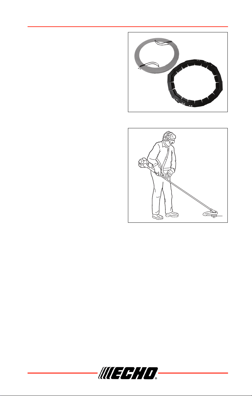
Use blade protectors to protect
blade teeth during unit
transportation.
Use Shoulder/Waist Harness
Use of the shoulder/waist harness is
recommended for ALL trimmer/
brushcutter use, not just blade
operation. The shoulder/waist
harness when used in a trimming
operation with nylon line head
suspends the trimmer from the
operator's shoulder and reduces
operator fatigue.
During blade operation, the same
fatigue reduction is achieved. Safety
to the operator is also enhanced by
reducing the possibility of blade
contact with the operator's hands and feet by restricting trimmer movement.
Make sure the warning sign on the back of the shoulder harness can be
read easily.
Note: In case of emergency, disconnect the trimmer from the
harness.
OPERATION DPAS-2600SB
26 X7508230800
©11/21 ECHO Incorporated
Starting The Unit
The attachment will operate when the battery is installed, the
power indicator LED is lit, and the trigger switch and trigger
switch lockout are engaged. Make sure the product is properly
positioned to prevent loss of control and possible serious
injury.
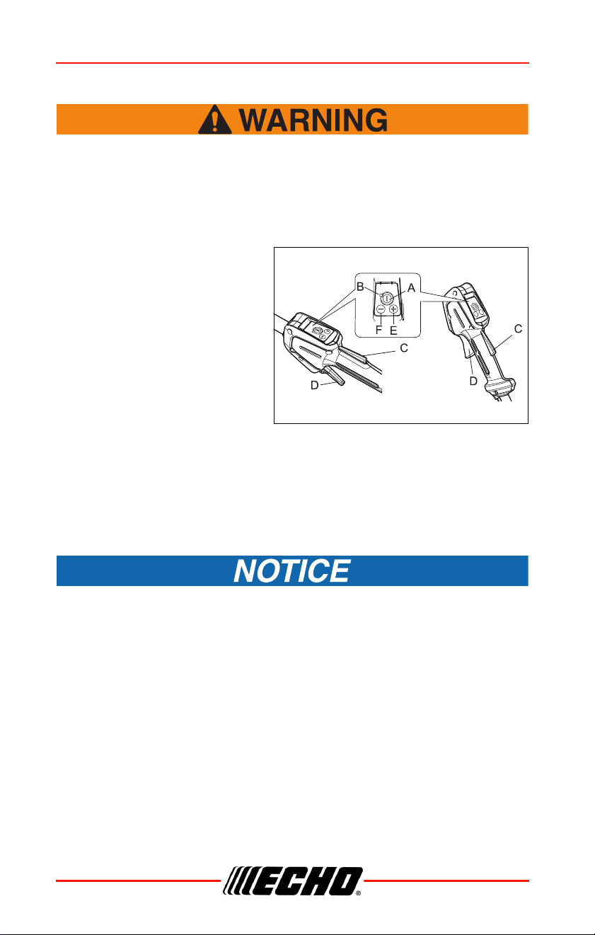
1. Keep movable parts of the
attachment away from
objects that could become
entangled or thrown, and
surfaces that could cause
loss of control.
2. Push power button (A) once
to turn on power to unit.
Power indicator LED (B)
illuminates when power to
unit is turned on.
3. Hold down trigger switch
lockout (C) and depress trigger switch (D) to increase RPM to operating
speed.
Note: To increase operating speed, press + (E). To decrease
operating speed, press - (F). Press and hold + button for one
second to maintain consistent speed. Press + again to
cancel.
When power to unit is turned on:
• After 90 seconds of inactivity, unit will power itself off.
• If the LED remains lit, operation is normal.
• If the LED flashes once per second, the battery needs to be charged.
• If the LED flashes four times per second, there is a fault within the
product. Turn power off to unit. Remove battery. Clear debris from around
line head. Install battery. Turn power on to unit. If flashing continues, have
your authorized servicing dealer repair the product.
DPAS-2600SB OPERATION
X7508230800 27
©11/21 ECHO Incorporated
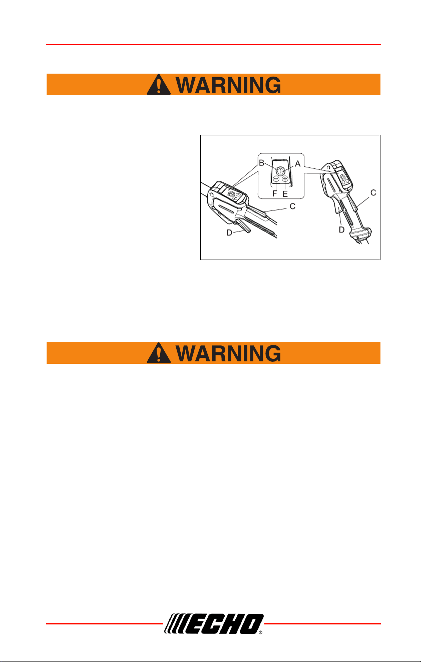
Stopping Unit
The attachment continues to run for a short period after the unit
is switched off.
1. Release trigger switch and
trigger switch lockout, and
allow attachment to stop.
2. Push power button (A) to
turn off power to unit.
• Power indicator LED (B) turns
off when power to unit is
turned off.
• If the attachment does not stop
when the trigger and trigger
lockout are released, push
power button to turn off and remove the battery to stop the power supply
to product. Have your authorized servicing dealer repair power button
before using product again.
Applications
Do Not install blades on GT (Curved Shaft) trimmers.
Operating Techniques - Nylon Line Head
Nylon line heads may be used for trimming, scything, edging, and scalping
of grass and light weeds.
Trimming
Feed the spinning line into the material to be cut. Tilt the line head to one
side to direct cutting debris away from you:
• Model SRM/DSRM/PAS/DPAS/SB/TX/C/T (Straight shaft, counter-
clockwise line head rotation) - Tilt the cutting head down on the right side
while cutting to direct cutting debris away from operator. Feed the line
gradually into the material you wish to cut, avoiding contact with fences or
other barriers.
• GT models: Tilt cutting head to the left while cutting to direct debris away
from the operator.

OPERATION DPAS-2600SB
28 X7508230800
©11/21 ECHO Incorporated
Scything
Scything - Swing the cutting head in a level arc, gradually feeding the line
into the material being cut. Move forward with each arc to cut a swath.
Width of cutting swath depends on arc. Use a larger arc for a wider swath,
or a smaller arc for a narrow swath. Keep line head tilted to direct cutting
debris forward or away from you.
Edging and Scalping
Both of these are done with the nylon line cutting head tilted at a steep
angle. Scalping is removing top growth, leaving the earth bare. Edging is
trimming the grass back where it has spread over a pavement or driveway.
During both edging and scalping, hold the unit at a steep angle in a position
where the debris, and any dislodged dirt and stone, will not come back
towards you even if it ricochets off the hard surface.
General
• Debris flows in direction of line head rotation. Change line head position
to assure debris flow is directed away from operator.
• Keep cutting line away from wire fences to avoid entanglement.
• Operate trimmer only with cutting head below knee height.
Operating Techniques - Metal or Plastic Blade
Brushcutter blades may be used to cut and trim a wide variety of materials.
Refer to the blade selection section for determining the correct blade for the
application.
Scything (3, 8, and 80 tooth weed/grass, and brush blades)
• To cut large sections of field grass and weeds swing the cutting head in a
level arc, gradually feeding the blade into the material being cut. Adjust
throttle speed according to your work.
• Do not swing the main pipe with arms. Turn hips to
swing the blade horizontally from right to left, and cut
weeds on the left side of the blade.
• Do not scythe back and forth as the grass may scatter
and kickback may occur easily.
• Tilt blade left by 5 to 10 degrees so that cut grasses will
push left, making progress easier.
• Move forward with each arc to cut a swath.

DPAS-2600SB OPERATION
X7508230800 29
©11/21 ECHO Incorporated
• Width of cutting swath depends on arc. Use a larger arc
for a wider swath, or a smaller arc for a narrow swath.
Suggested cutting width is about 1.5 m (4.9 ft).
• When scything large brush up to 0.5" diameter from
right to left, avoid cutting with highlighted section.
Reaction Forces
◆ The cutting attachment will continue to rotate even after
the throttle is released, maintain control of the unit until it
has come to a complete stop.
◆ Blade thrust may occur when the spinning blade contacts
an object that it does not immediately cut. Following
proper cutting techniques will prevent blade thrust.
◆ Blade thrust can be violent enough to cause the unit and/or
operator to be propelled in any direction, and possibly lose
control of the unit.
◆ Blade thrust can occur without warning if the blade snags,
stalls or binds.
◆ Blade thrust is more likely to occur in areas where it is
difficult to see the material being cut.
Push or Pull - Kickout
During normal use, operating a brushcutter with a circular metal blade can
produce sudden strong reaction forces that are difficult to control. Strong
reaction forces can cause a loss of balance or loss of control of the
equipment, resulting in serious injury to operator and bystanders.
Understanding what causes these reactive forces may help you to avoid
them, and can help you to maintain control of the equipment if you
experience a sudden reaction during cutting. Reactive forces occur when
the force being applied by the cutting teeth of a blade meet resistance, and
some of the cutting force is directed back toward the equipment. The
greater the cutting force or the amount of resistance, the greater the
reactive force.
OPERATION DPAS-2600SB
30 X7508230800
©11/21 ECHO Incorporated
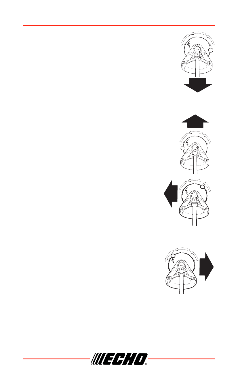
Push and Pull Forces
Push and pull forces are reactive forces that push the
equipment directly toward the operator, or that pull the
equipment directly away from the operator. These forces are
the result of cutting on the sides of the blade. The direction of
the force depends on the side of the blade being used, and
the direction of blade rotation at the point of contact. The
reactive force is in the opposite direction of blade rotation at
the contact point, regardless of where the contact is being
made. These types of reactive forces are also called “Blade
Thrust.”
As shown in the illustration, a blade turning
counterclockwise will cause the equipment to pull away
from the operator if the point of cutting resistance is on the
left side of the blade. If the point of cutting resistance is on
the right side of the blade, the equipment will push back
toward the operator. In both examples, the reactive force is
in the opposite direction of blade rotation at the contact
point where resistance occurs.
Kickout
Kickout is also a reactive force caused by resistance
to cutting, but the direction of blade thrust is lateral (to
the left or right of the blade), instead of forward or
back toward the operator. In most cases, Push, Pull,
and Kickout can be reduced or eliminated by:
• Using the correct blade for the cutting job
• Using properly sharpened blades
• Applying consistent, even force to the blade during
the cut
• Avoiding obstacles and ground hazards
• Using extra care when cutting harder materials
such as extremely dry brush, saplings, and small
trees
• Cutting from a stable, secure position
DPAS-2600SB OPERATION
X7508230800 31
©11/21 ECHO Incorporated
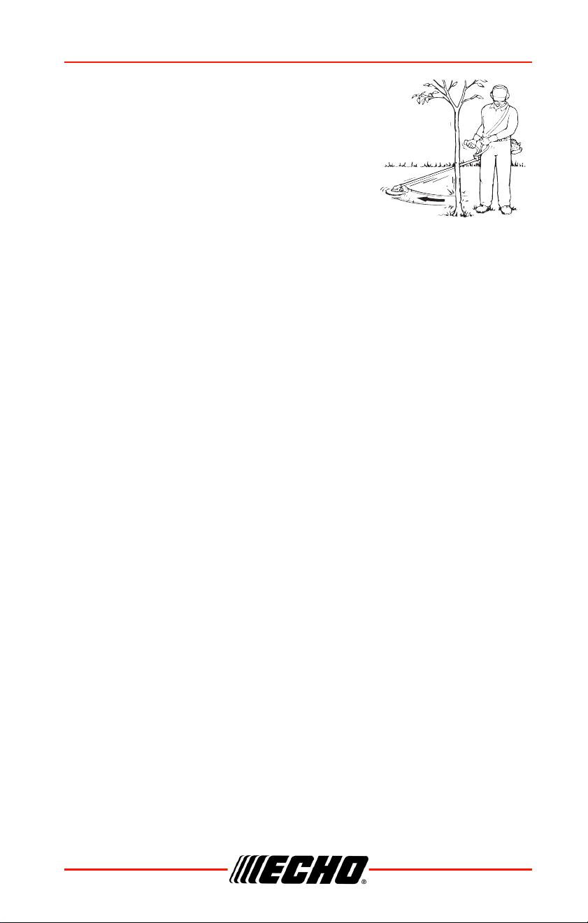
Blade Cutting Problems
Binding - Blades may bind in the cut if dull or
forced. Binding can damage blade, and result in
blade breakage or injury from fragments and
flying debris. If a blade binds in a cut, don’t try to
get it out by applying “up and down” force to pry
the cut open. Applying prying force to the blade
can bend the blade, and result in blade failure
and injury.
To free a blade that is bound in the cut, stop the unit, and support the
trimmer or brushcutter to keep stress off the blade. Push the tree away from
the entry point of the cut to open the cut, and pull the blade directly away
from the cut in a straight-line motion. Use caution when releasing the tree to
avoid being struck by spring-back or falling.
Inspect the blade for damage before proceeding. Sharpen teeth if dull, or
replace blade if cracked, bent, missing teeth, or otherwise damaged.
To prevent binding:
• Keep blades sharp
• Avoid excessive pressure during cuts
• Don’t exceed cutting capacity of blade
• Don’t use blades with damaged or missing cutting teeth
• Don’t rock blades in cut

MAINTENANCE DPAS-2600SB
32 X7508230800
©11/21 ECHO Incorporated
MAINTENANCE
Moving parts can amputate fingers or cause severe injuries.
Keep hands, clothing and loose objects away from all openings.
Always stop unit and make sure all moving parts have come to
a complete stop before removing obstructions, clearing debris,
or servicing unit. Allow unit to cool before performing service.
Wear gloves to protect hands from sharp edges and hot
surfaces.
Operating a poorly maintained unit can result in serious injuries
to operator or bystanders. Always follow all maintenance
instructions as written, otherwise serious personal injury can
result.
Your unit is designed to provide many hours of trouble free service. Regular
scheduled maintenance will help your unit achieve that goal. If you are
unsure or are not equipped with the necessary tools, we recommend that
you take your unit to a Servicing Dealer for maintenance. To help you
decide whether you want to DO-IT-YOURSELF or have the Dealer do it,
each maintenance task has been graded. If the task is not listed, see your
Dealer for repairs.
Skill Levels
Level 1 = Easy to do. Common tools may be required.
Level 2 = Moderate difficulty. Some specialized tools may be required.
Level 3 = See your dealer.
Click HERE or go to http://www.echo-usa.com/products/maintenance-kit
or
HERE https://www.shindaiwa-usa.com/you-can.aspx

DPAS-2600SB MAINTENANCE
X7508230800 33
©11/21 ECHO Incorporated
Maintenance Intervals
MAINTENANCE PROCEDURE NOTES:
1
Apply lithium based grease every 25 hours of use.
2
Apply lithium based grease every 50 hours of use.
If not maintained properly, the product may pose a serious risk
to physical health.
If not maintained properly, the product's performance may
deteriorate. Time intervals shown are maximum. Actual use and your
experience will determine the frequency of required maintenance. If
you continuously use vegetable based chain oil, inspect and do
maintenance often. When you find anything wrong, ask your ECHO
dealer for repair.
COMPONENT OR
SYSTEM
MAINTENANCE PROCEDURE Skill Level
Daily Or Before Use
Battery / Battery
Compartment
Inspect / Clean / Charge
1
Cut Off Knife Inspect / Clean 1
Screws / Nuts / Bolts Inspect / Tighten / Replace 1
Drive Shaft Grease
1
1
Gear Housing Grease
2
1
MAINTENANCE DPAS-2600SB
34 X7508230800
©11/21 ECHO Incorporated
Maintenance and Care
Remove battery before performing maintenance procedures.
Cleaning battery and battery compartment
Risk of electric shock or fire. Do not use conducting materials
to clean battery or battery compartment. Otherwise serious
personal injury may result.
1. Release trigger switch and trigger switch lockout and allow trimmer
head to stop.
2. Make sure power indicator LED is not illuminated.
3. Depress battery latch release
(A) and slide battery out of
power head.
4. Use compressed air or a soft
bristle brush to remove debris
from battery and battery
compartment.
Cut-Off Knife
Wear gloves or personal injury may result:
◆ Cut-off knife is sharp.
◆ Gearcase and surrounding area may be hot.
1. Inspect cut-off knife (B) for
damage or wear. Assure that it
is properly attached to debris
shield.
A
B
DPAS-2600SB MAINTENANCE
X7508230800 35
©11/21 ECHO Incorporated
Lubrication
Level 1.
Parts Required: Lithium Based Grease.
Gear Case
Gear cases without grease plug (A) do not require lubrication.
1. Clean all loose debris from gear
case.
2. Remove plug (A) and check
level of grease.
3. Add grease if necessary. DO
NOT over-fill.
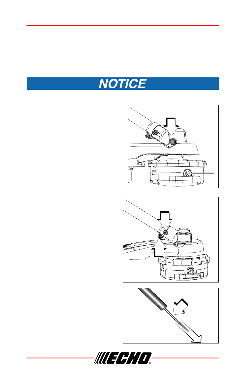
Drive Shaft (Lower)
1. Loosen screw (B) and remove
locating screw (C). Pull gear
case and shield from drive shaft
housing.
2. Pull flexible cable (D) from the
drive shaft housing, wipe clean
and re-coat with 15 ml (0.5 oz.)
of grease.
3. Slide the flexible cable (D) back
in the drive housing. DO NOT
get dirt on the flex cable.
4. Install the gear housing and
shield assembly.
A
B
C
D
MAINTENANCE DPAS-2600SB
36 X7508230800
©11/21 ECHO Incorporated
Drive Shaft (Upper)
1. Loosen handle clamping screw
(B) and slide throttle handle
forward.
2. Loosen clamping screw (C)
and slide shaft out of power
head.
3. Pull flex cable (D) out of shaft
housing, wipe clean and re-
coat with 15 ml (0.5 oz.)
grease.
4. Slide flex cable (D) back into
shaft housing. DO NOT get dirt
on flex cable.
5. Reassemble in reverse order.
Nylon Line Replacement
Wear gloves or personal injury may result:
◆ Cutoff knife is sharp.
◆ Gearcase and surrounding area may be hot.
Never use wire or wire-rope that can break off and become a
dangerous “projectile”. Serious injury can occur.
B
C
D
DPAS-2600SB MAINTENANCE
X7508230800 37
©11/21 ECHO Incorporated
1. Cut one piece of line to
recommended length.
2.0 mm (0.080 in.) diameter
6 m (20 ft.).
2.4 mm (0.095 in.) diameter
6 m (20 ft.).
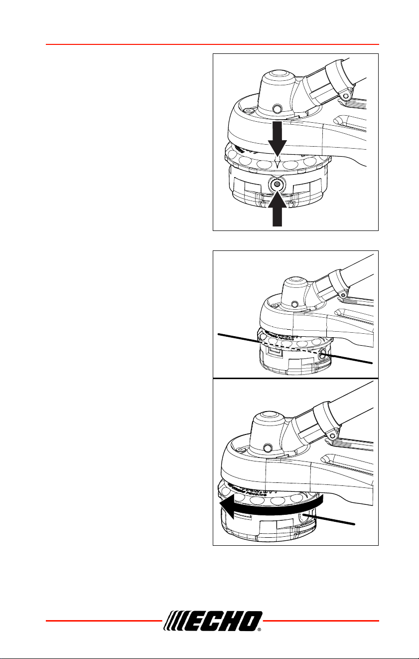
2. Align arrows on top of knob with
openings in eyelets.
3. Insert one end of trimmer line
into an eyelet, and push line
equal distance through trimmer
head.
4. Hold trimmer head while turning
knob clockwise to wind line
onto spool until about 13 cm
(5 in.) of each line remains
exposed.
Trimmer head is now fully loaded
and ready for operation.
MAINTENANCE DPAS-2600SB
38 X7508230800
©11/21 ECHO Incorporated
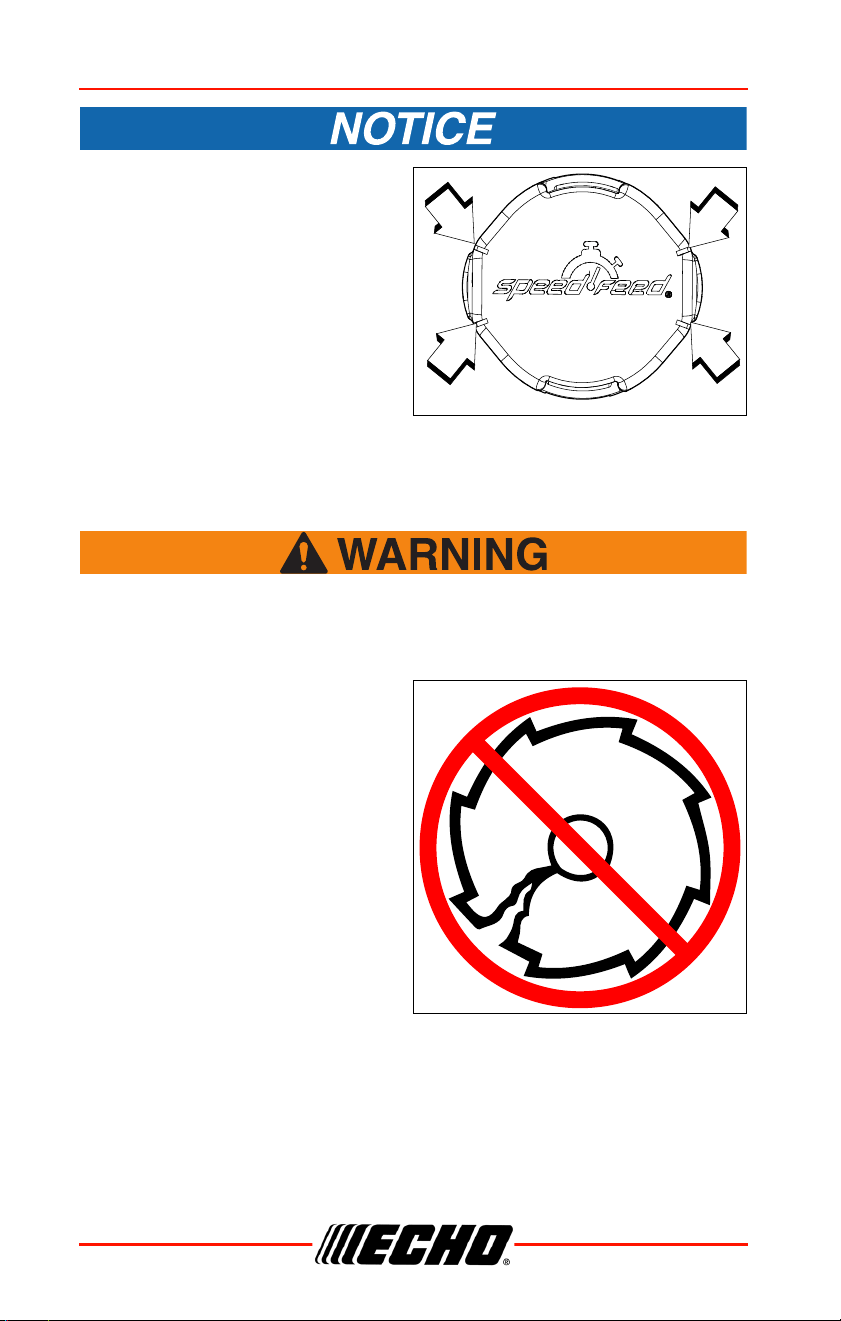
When the wear indicators
located at the bottom of the
Speed-Feed
®
head are worn
smooth, or if holes appear,
replacement of the cover or the
entire Speed-Feed
®
head
required.
Sharpening Metal Blades
Metal blades are very sharp and can cause severe injuries, even
if unit is off and blades are not moving. Avoid contact with
blades. Wear gloves to protect hands.
Several styles of metal blades are
approved for use on the
Brushcutter. The 8-tooth blade can
be sharpened during normal
maintenance. The clearing blade
and 80-tooth blade require
professional service.
Before sharpening, CLOSELY
inspect blade for cracks (look at the
bottom of each tooth and the center
mounting hole closely), missing
teeth and bending. If ANY of these
problems are discovered, replace
the blade.
When sharpening a blade, always
remove the same amount of materials from each tooth to maintain balance.
A blade that is not balanced will cause unsafe handling due to vibration and
can result in blade failure.
DPAS-2600SB MAINTENANCE
X7508230800 39
©11/21 ECHO Incorporated
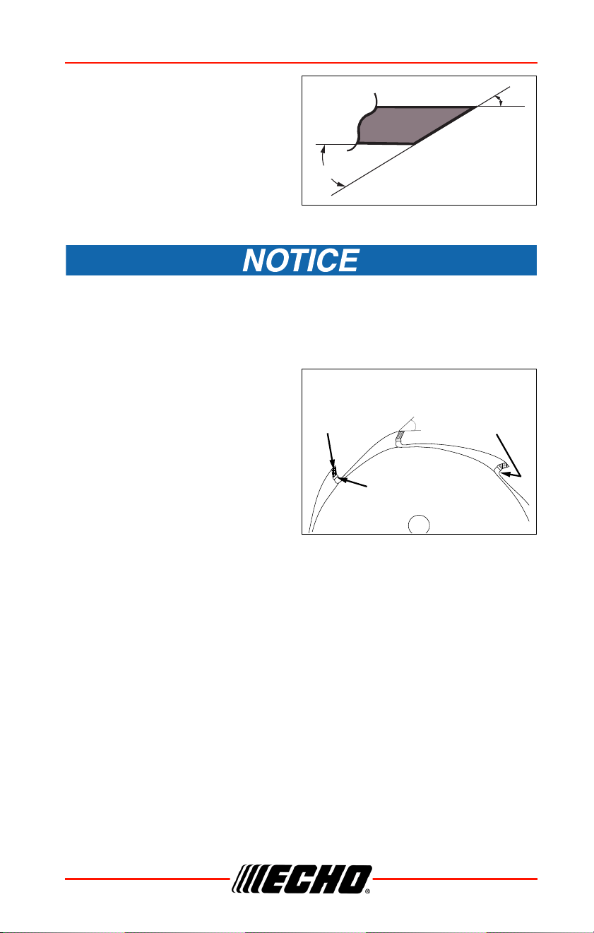
1. File each tooth at a 30° angle a
specific number of times, e.g.,
four strokes per tooth. Work
your way around the blade until
all teeth are sharp.
2. DO NOT file the ‘gullet’ (radius)
of the tooth with the flat file. The
radius must remain. A sharp
corner will lead to a crack and
blade failure.
If an electric grinder is used, use care not to overheat teeth, do not
allow tips/tooth to glow red or turn blue. DO NOT place blade in
cooling water. This will change the temper of the blade and could
result in blade failure.
3. After sharpening teeth, check
each tooth radius for evidence
of a square (sharp) corner. Use
the round (rat tail) file to renew
the radius.
30º
30º
30º
CUTTING
TOOTH
AREA
CUTTING
TOOTH
RADIUS
GULLET
(RADIUS)

TROUBLESHOOTING DPAS-2600SB
40 X7508230800
©11/21 ECHO Incorporated
TROUBLESHOOTING
TROUBLESHOOTING CHART
Problem Cause Remedy
Red Charger light
flashes or does not light
up
Plug not connected
to power outlet.
Plug in charger.
Battery pack not
installed properly.
Check the battery
installation.
Obstructed
connection.
Reinstall battery after
removing obstructions.
Fault in the charger. Consult your dealer.
Fault in the battery
pack.
Consult your dealer.
Unit will not turn on
Battery pack not
installed properly.
Check battery
installation.
Unit does not run when
turned on
Battery pack
discharged.
Charge battery .
Battery pack outside
acceptable
temperature range.
Remove the battery
and allow to cool.
Running time is too
short
Battery pack outside
acceptable
temperature range.
Remove battery and
allow to cool.
Unit electronics too
hot.
Turn unit off and allow
to cool.
Battery pack
discharged.
Charge the battery.

DPAS-2600SB STORAGE
X7508230800 41
©11/21 ECHO Incorporated
STORAGE
Storage
Do not store in an enclosure where combustible fumes may
accumulate. Fire may result.
When storing the product for long periods of time, ensure that the following
preparations for storage are carried out.
Unit
Do not store your unit without performing protective storage maintenance
which includes the following:
1. Turn power to unit off.
2. Remove battery.
3. Remove accumulation of dirt and debris from exterior of unit.
4. Tighten all screws and nuts.
5. Cover battery compartment, battery and charger.
6. Store unit in a dry, dust-free place out of the reach of children.
Battery
1. Remove battery.
2. Store in a dry, dust-free place, out of the reach of children.
3. Store in temperatures between -20
o
C (-4 F) and 60
o
C (140 F).
4. If battery is stored for longer than six months, charge it to 100%
capacity.
Charger
1. Remove battery from charger.
2. Disconnect charger from power supply.
3. Store in a dry, dust-free place, out of the reach of children.
STORAGE DPAS-2600SB
42 X7508230800
©11/21 ECHO Incorporated
Disposal
Major plastic parts making up the product have codes
showing their materials. The codes refer to the
following materials; dispose of those plastic parts in
accordance with local regulations.
• Battery contains lithium. Dispose of only at a designated collection point.
• Lithium-ion batteries must be disposed of properly.
• Please contact your dealer in case you do not know how to dispose of or
recycle waste plastic parts.
Materials
Mark Material
>PA6-GF< Nylon 6 - Glass fiber
>PP-GF< Polypropylene - Glass fiber
>PE-HD< Polyethylene
>PP< Polypropylene

DPAS-2600SB SPECIFICATIONS
X7508230800 43
©11/21 ECHO Incorporated
SPECIFICATIONS
* For best unit run time, use 0.095” Silentwist
TM
trimmer line. Other 0.095”
line might shorten run time.
MODEL DPAS-2600
Length (with trimmer attachment) 1851 mm (72.87in.)
Width (with trimmer attachment) 215 mm (8.46 in.)
Height (with trimmer attachment) 297 mm (11.69 in.)
Weight (with battery, with trimmer
attachment)
5.2 kg (11.46 lb)
Battery ECHO eFORCE™ 56V series batteries
Type Li-Ion
Battery voltage 56 V (rated 50.4)
Capacity See battery manual
Charger type ECHO eFORCE™ 56V series charger
Charger input voltage 120 V AC 60 Hz
Charging time See battery manual
Operating Rod 25.0 mm (0.98 in.) aluminum tube
Drive Shaft 6.15 mm (0.25 in.) flexible shaft
Cutter Head
Speed Feed
®
400 LH nylon line head, line
capacity 6.1 m (20 ft ) 0.095 trimmer line*.
Rotating Direction Counterclockwise, viewed from top
Motor Type DC / Brushless
Speed 4860 - 9200 RPM
Gear Case Ratio 1.62:1
Green blinking - battery is charging
Green - battery is fully charged
Red - Battery is too warm. Remove for
approximately 30 minutes to cool down.
Red blinking - Defective battery. Remove and
replace with new battery
Charger Lights
OFF Green blinking
OFF Green
Red OFF
Red OFF
blinking

SPECIFICATIONS DPAS-2600SB
44 X7508230800
©11/21 ECHO Incorporated
ECHO Optional Attachments
Use only ECHO attachments. Serious injury may result from the
use of non-ECHO attachment combinations. Read and comply
with all safety instructions listed in this manual and attachment
manual. ECHO Incorporated will not be responsible for the
failure of cutting devices, attachments or accessories which
have not been tested and approved by ECHO for use with these
units.
RECOMMENDED OPTIONAL ATTACHMENTS
Articulating Hedge Trimmer 99944200596
Brushcutter 99944200601
Bed Redefiner 99944200465
Curved Shaft Edger 99944200470
Straight Shaft Edger 99944200475
Hedge Trimmer 99944200486
Mid-Reach Hedge Trimmer 99944200640
Pro Paddle™ 99944200620
Pro Sweep™ 99944200553
Power Blower 99944200490
Tiller/Cultivator 99944200513
Power Pruner™ 99944200532
Speed-Feed® Trimmer 99944200540
Rapid Loader™ Curved Shaft Trimmer 99944200615
Pro-Torque Trimmer 99944200545
0.91 m (3.0 ft.) Extension* 99944200536
*
F
or use with: Articulating Hedge Trimmer, Hedge Trimmer, and Power Pruner
™
Atta
chments ONLY.

DPAS-2600SB WARRANTY
X7508230800 45
©11/21 ECHO Incorporated
WARRANTY
Limited Warranty
Handhel
in USA
ECHO Inc
that this E
fects in m
place, at
uct free of
purchase:
If the
•
•
If the
•
•
If the
ies, and
Cutting
chains
nylon
ducing
material
nal produc
rental
or other
This warrant
commenc
Any part
ECHO Inc
will be repai
by an aut
sories repl
balance of
The produc
an author
pense of
ranty work
after repai
Incorporat
making t
breach of
of the cont
uct. Proof
tiate any
by an aut
This warrant
has been
or that has
instructions
ranty does
posure, and
proper mai
dirt, abras
sion, varnish,
Limited Warranty Statement for ECHO 56 Volt
Handheld Products and Walk Behind Mowers sold
in USA and Canada
ECHO Incorporated warrants
to the original retail purchaser
that this ECHO brand 56 Volt outdoor product is free from de-
fects in material and workmanship and agrees to repair or re-
place, at ECHO Incorporated’s discretion, any defective prod-
uct free of charge within these time periods from the date of
purchase:
If the product is for homeowner use:
• Units and Bare Tool – 5 Years
• Battery or charger – 2 years
If the product is for commercial use:
• Units and Bare Tool – 2 years
• Battery or charger – 2 years
If the product is for rental use: 90 days for all units, batter-
ies, and chargers.
Cutting attachments such as, but not limited to, bars,
chains, sprockets, blades, tines, belts, PowerBroom
TM
and
nylon trimmer heads for homeowner or non-income pro-
ducing use will be covered for failures due to defects in
material or workmanship for a period of 60 days from origi-
nal product purchase date and 30 days for commercial /
rental use. Any misuse from contact with concrete, rocks,
or other structures is not covered by this warranty.
This warranty extends to the original retail purchaser only and
commences on the date of the original retail purchase.
Any part of this product found in the reasonable judgment of
ECHO Incorporated, to be defective in material or workmanship
will be repaired or replaced without charge for parts and labor
by an authorized
ECHO dealer. Units, repair parts and acces-
sories replaced under this warranty are warranted only for the
balance of the original warranty period.
The product, including any defective part, must be returned to
an authorized
ECHO dealer within the warranty period. The ex-
pense of delivering the product to the service center for war-
ranty work and the expense of returning it back to the owner
after repair or replacement will be paid by the owner. ECHO
Incorporated’s, responsibility in respect to claims is limited to
making the required repairs or replacements and no claim of
breach of warranty shall be cause for cancellation or rescission
of the contract of sale of any ECHO brand 56 Volt outdoor prod-
uct. Proof of purchase will be required by the dealer to substan-
tiate any warranty claim. All warranty work must be performed
by an authorized ECHO
dealer.
This warranty does not cover any units, battery or charger that
has been subject to misuse, neglect, negligence, or accident,
or that has been operated in any way contrary to the operating
instructions as specified in the Operator’s Manual. This war-
ranty does not cover normal deterioration due to the use or ex-
posure, and any repairs made necessary by normal wear, im-
proper maintenance, improper lubrication, improper storage,
dirt, abrasives, impact, moisture, water, rain, snow, rust, corro-
sion, varnish, or other similar conditions.
This warranty does not cover damage to chargers or batteries
by improper charging voltage and batteries that have been ex-
posed to temperatures beyond those specified in the Opera-
tor’s Manual, batteries that have not been properly charged or
batteries that have reached their useful life.
This warranty does not apply to any
damage to the product that
is the result of improper maintenance or to any product that has
been altered or modified. The warranty does not extend to re-
pairs made necessary by normal wear or by the use of parts or
accessories which are either incompatible with the ECHO
brand 56 Volt outdoor product or adversely affect its operation,
performance, or durability. In addition, this warranty does not
cover wear to normal items such as, but not limited to:
Wear items – Bump Knobs, Outer Spools, Cutting Lines, Inner
Reels, Felt Washers, Hitch Pins, Mulching Blades, Blower
Fans, Blower and Vacuum Tubes, Vacuum Bag and Straps,
Guide Bars, Saw Chains,
Grass Catch Bag, Hedge Trimmer
Blades, and Wheels
ECHO Incorporated, reserves the right to change or improve
the design of this product without assuming any obligation to
modify any product previously manufactured.
All implied warranties are limited in duration to the stated war-
ranty period. Accordingly, any such implied warranties includ-
ing merchantability, fitness for a particular purpose, or other-
wise, are disclaimed in their
entirety after the expiration of the
appropriate
five-year, two-year, one-year, 90-day, 60-day, or
30-day warranty period.
ECHO Incorporated’s
obligation under
this warranty is strictly and
exclusively limited to the repair or re-
placement
of defective parts. ECHO Incorporated, does not as-
sume or
authorize anyone to assume for them any other obliga-
tion. Some states do not allow limitations
on how long an implied
warranty lasts, so the above limitation may not apply to you.
ECHO Incorporated, assumes no responsibility for incidental, con-
sequential,
or other damages including, but not limited to, ex-
pense of returning the product to an authorized
dealer for
ECHO brand 56 Volt outdoor products and expense of deliver-
ing it back to the owner, mechanic’s travel time, telephone
charges, rental of a like product during the time warranty ser-
vice is being performed, travel, loss or damage to
personal prop-
erty, loss of revenue, loss of use
of the product, loss of time, or
inconvenience. Some states do not allow the exclusion or limi-
tation of incidental or consequential damages, so the above
limitation or exclusion may not apply to you.
This warranty gives you specific legal rights, and you may also
have other rights which vary from state to state.
This warranty applies to all ECHO brand 56 Volt outdoor prod-
ucts manufactured by or for ECHO Incorporated, and sold in
the United States and Canada.
To locate your nearest authorized ECHO dealer, visit
www.ECHO-usa.com or dial 1-800-432-ECHO (3246).
99922205724
11/2022

PRODUCT REGISTRATION DPAS-2600SB
46 X7508230800
©11/21 ECHO Incorporated
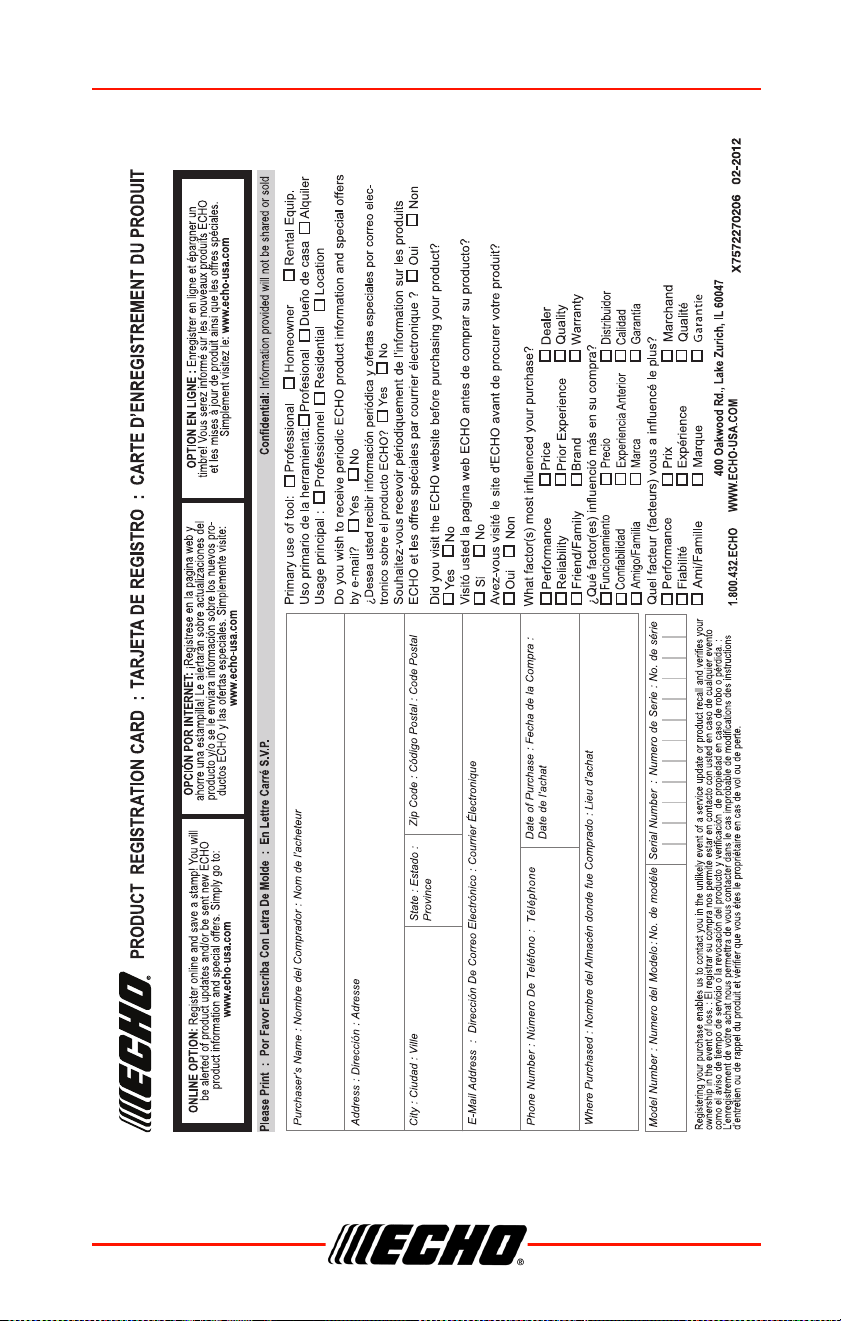
PRODUCT REGISTRATION
Thank you for choosing ECHO Power Equipment
Please go to http://www.echo-usa.com/Warranty/Register-Your-ECHO
to
register your new product on-line. It's FAST and EASY! NOTE: your
information will never be sold or misused by ECHO, Incorporated.
Registering your purchase enables us to contact you in the unlikely event of
a service update or product recall, and verifies your ownership for warranty
consideration.
If you do not have access to the Internet, you can complete the form below
and mail to:
ECHO Incorporated, Product Registration, PO Box 1139,
Lake Zurich, IL 60047.
DPAS-2600SB PRODUCT REGISTRATION
X7508230800 47
©11/21 ECHO Incorporated
ECHO Incorporated