
1. SAFETY
9 Before each use, check that there is no damage to the spreader and that all fixings are tight.
9 Replace or repair damaged parts. Use only recommended parts. Unauthorised parts may be dangerous and will invalidate the
warranty.
9 Ensure that the operator is fully trained and competent to operate the spreader.
9 Ensure that all chemical safety instructions are adhered to when handling products for use in the spreader. A full range of personal
safety equipment is available from your Sealey stockist.
9 Ensure all non essential personnel keep a safe distance when the spreader is in use.
8 DO NOT place hands inside the hopper during spreading.
8 DO NOT over inflate the tyres, 25psi (1.7bar) maximum.
8 DO NOT overload the spreader - see Specification.
8 DO NOT leave unattended, especially when loaded.
8 DO NOT allow anybody to sit, stand, or ride on the spreader.
8 DO NOT allow untrained personnel to use the spreader.
8 DO NOT allow children to play in or climb onto the spreader.
8 DO NOT use on windy days when spreading seeds or herbicides.
8 DO NOT tow this spreader with a motorized vehicle of any sort.
8 DO NOT use the spreader for purposes other than for which it is designed.
8 DO NOT operate the spreader when you are tired or under the influence of alcohol, drugs or intoxicating medicines.
8 DO NOT operate the spreader over edges, rough surfaces etc., where the spreader is at risk of overturning.
WARNING! Failure to comply with these instructions may result in damage to spreader or other property and/or personal injury.
WARNING! The warnings, cautions and instructions in this manual cannot cover all possible conditions and situations that may
occur. It must be understood by the operator that common sense and caution are factors which cannot be built into this
product, but must be applied by the operator.
NOTE: This appliance is not intended for use by persons (including children) with reduced physical, sensory or mental capabilities or lack
of experience and knowledge, unless they have been given supervision or instruction concerning the use of the appliance by a
person responsible for their safety. Children should be supervised to ensure that they do not play with the appliance.
2. INTRODUCTION
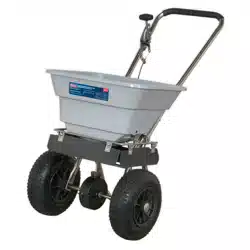
Manufactured with a strong tubular steel frame and polypropylene dispensing hopper. Features corrosion resistant stainless steel feed
system ideal for spreading salt and grit. Fitted with nylon gear and adjustable feed system. Sprays in 360° motion to cover a large area.
Suitable for a variety of horticultural agents including grit, seed, salt, fertilizer and weedkiller.
3. SPECIFICATION
Model No: ............................................................... SSB37W
Capacity (Volume): ...........................................................29L
Capacity (Weight): ..........................................................37kg
Dimensions (W x D x H): ......................... 550 x 940 x 860mm
Spread: .......................................................................3-3.6m
37KG WALK BEHIND STAINLESS STEEL
BROADCAST SALT SPREADER
MODEL NO: SSB37W
Thank you for purchasing a Sealey product. Manufactured to a high standard, this product will, if used according to these
instructions, and properly maintained, give you years of trouble free performance.
IMPORTANT: PLEASE READ THESE INSTRUCTIONS CAREFULLY. NOTE THE SAFE OPERATIONAL REQUIREMENTS, WARNINGS & CAUTIONS. USE
THE PRODUCT CORRECTLY AND WITH CARE FOR THE PURPOSE FOR WHICH IT IS INTENDED. FAILURE TO DO SO MAY CAUSE DAMAGE AND/OR
PERSONAL INJURY AND WILL INVALIDATE THE WARRANTY. KEEP THESE INSTRUCTIONS SAFE FOR FUTURE USE.
Refer to
instruction
manual
SSB37W Issue 4 14/04/23
Original Language Version
© Jack Sealey Limited
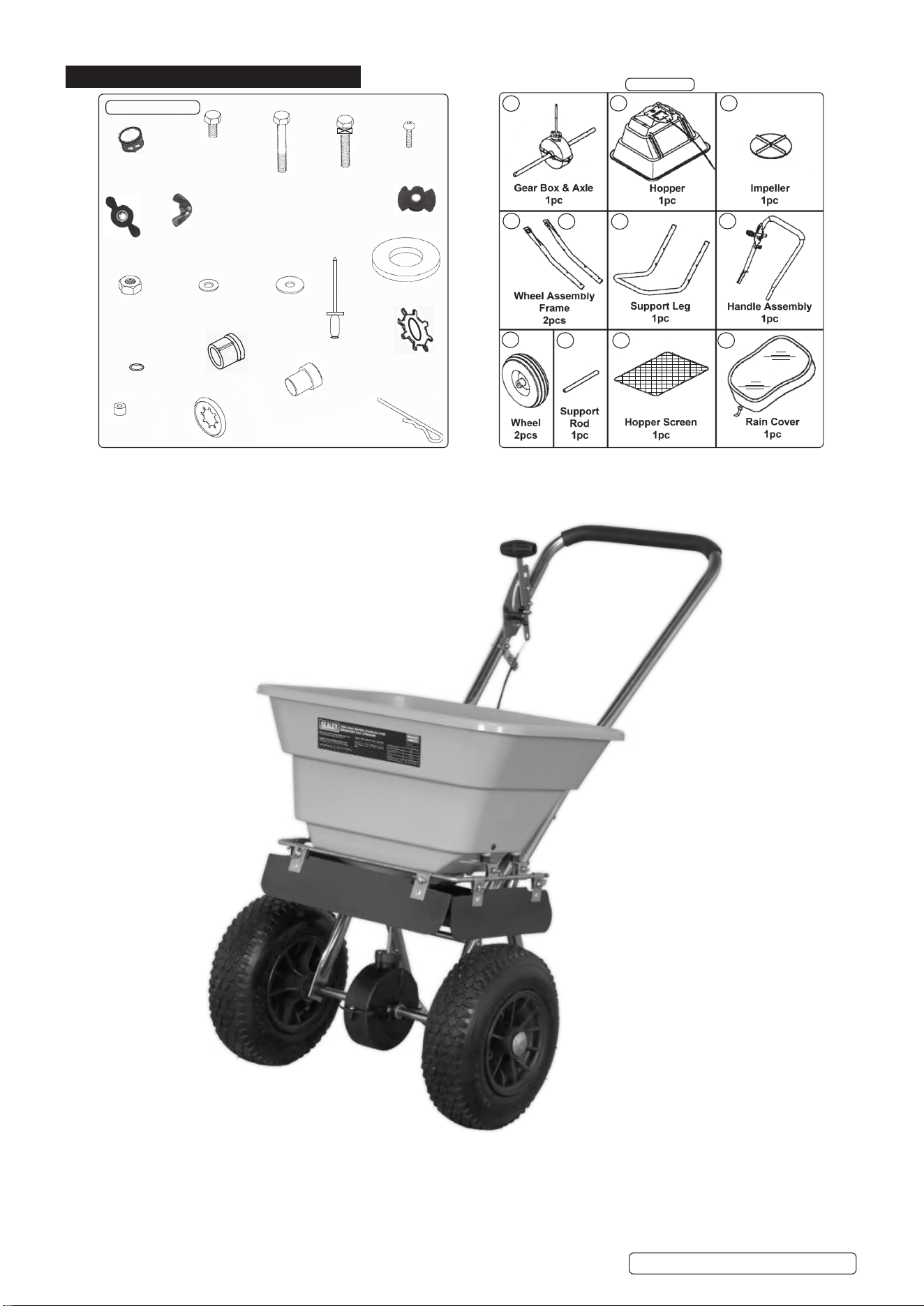
4. CONTENTS
(7)
(35)
(2)
(30)
(12)
(31)
(32)
(1)
(52)
(21)
(25)
(28)
(40)
(41)
(33)
(9)
(17)
(39)
(14)
(20)
(24)
(36)
(60)
(50)
(59)
(51)
(13)
(10)
(44)
Fixings/Bushes
(23)
34
11 19
27
26
42
47 49 48
18
29
Main Items
(15)
SSB37W Issue 4 14/04/23
Original Language Version
© Jack Sealey Limited

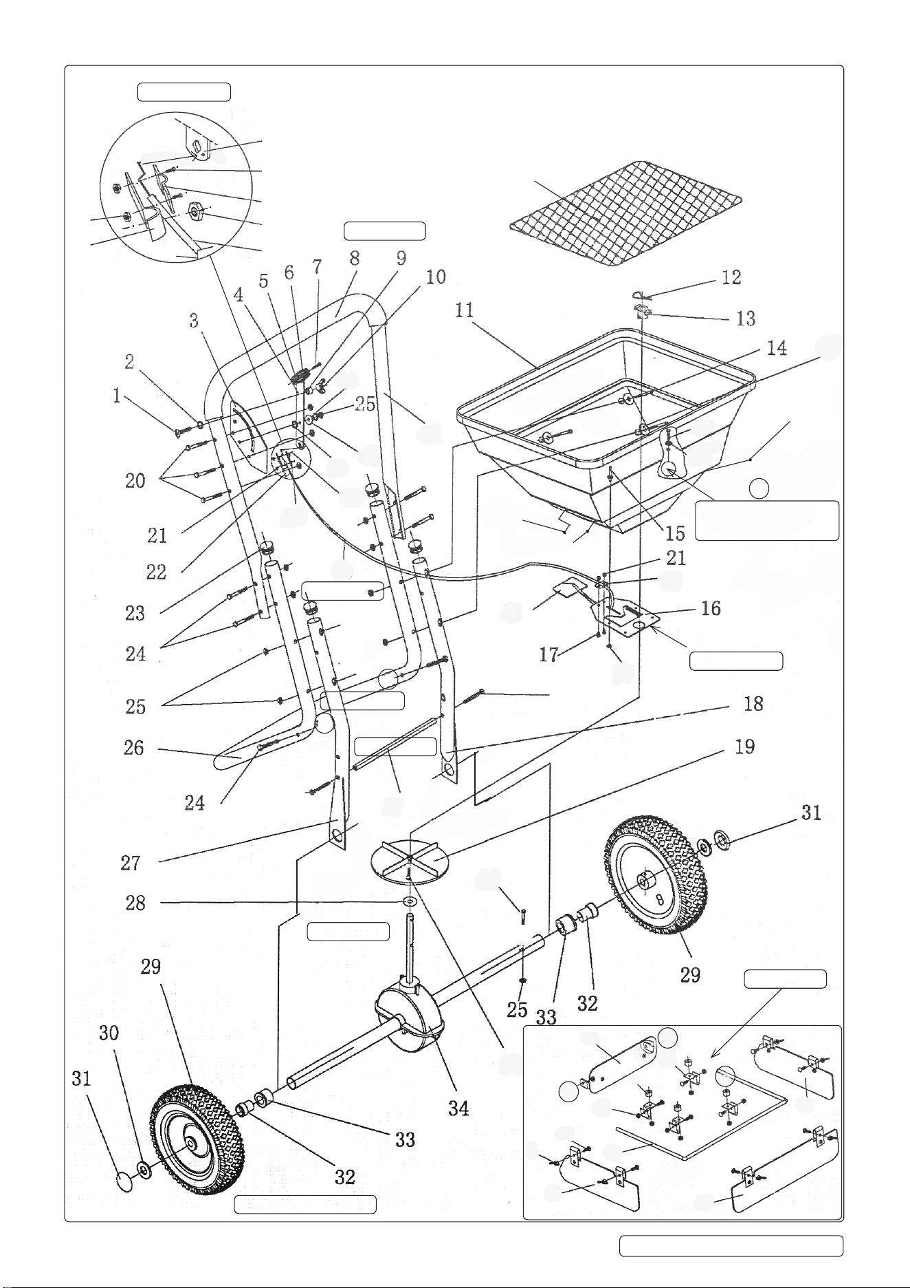
Item Description Qty Item Description Qty
1 Carriage Bolt M6x25 1 31 Axle End Cover 2
2 External Serrated Washer Ø8 1 32 Inner Axle Bushing 2
3 Gauge and Level Sub Assembly 1 33 Outer Axle Bushing 2
4 Adjuster Lever 1 34 Gearbox and Axle Sub Assembly 1
5 Split Handle 1 35 Screw M4x20 1
6 Split Handle 1 36 Hex Bolt M6x60 1
7 Round Head Screw M4x18 2 37 Clamp Plate 2
8 Handle Grip 1 38 Hopper Control Cable 1
9 Plastic Spacer 5 39 Hex Screw M5x10 2
10 Plastic Clamp Knob 1 40 Nylon Washer 1
11 Hopper 1 41 Large Flat Washer Ø6 5
12 "R" Pin Ø2.5x80 (Agitator) 1 42 Handle Bar 1
13 Centre Hub (Plastic) 1 43 Throat Plate 1
14 Hex Bolt M6x70 4 44 Single Coil Spring Washer Ø6 1
15 Pop Rivet Ø5x13 4 45 Large Plug 1
16 Guide Plate 1 46 Small Plug 2
17 Hex Screw M5x12 4 47 Support Rod 1
18 Frame Fork (Left) 1 48 Rain Cover (not shown in diagram) 1
19 Impeller 1 49 Hopper Grille Screen 1
20 Hex Bolt M6x35 5 50 Flat Washer Ø5 4
21 Hex Theadlock Nut M5 4 51 Wing Nut M6 6
22 Anchor Bracket 1 52 Carriage Bolt M6x20 10
23 TubeEndCap 4 53 LeftDeector 1
24 Hex Bolt M6x40 6 54 Boom Rail 1
25 HexThreadlockNutM6 23 55 FrontDeector 1
26 SupportLeg 1 56 RightDeector 1
27 Frame Fork (Right) 1 57 Clamp Bracket 4
28 ThinPlasticWasher 1 58 RearDeector 1
29 Pneumatic Wheel 2 59 Flat Washer Ø6 4
30 Flat Washer Ø16 2 60 Hex Bolt M6x30 4
PARTS LIST
SSB37W Issue 4 14/04/23
Original Language Version
© Jack Sealey Limited
4
39
37
25
38
21
22
49
COMPOSITE EXPLODED PARTS DIAGRAM
Seeg.12
39
Seeg.9and
view bottom right
Seeg.5
Seeg.4&g.6
Seeg.1
Seeg.9
Seeg.2
Seeg.3
Seeg.7
38
37
41
60
59
37
50
43
47
36
58
53
51
54
55
56
25
9
57
52
44
42
40
41
35
A
B
A
B
C
C
Seeg.9
45
46
46
20
20
SSB37W Issue 4 14/04/23
Original Language Version
© Jack Sealey Limited
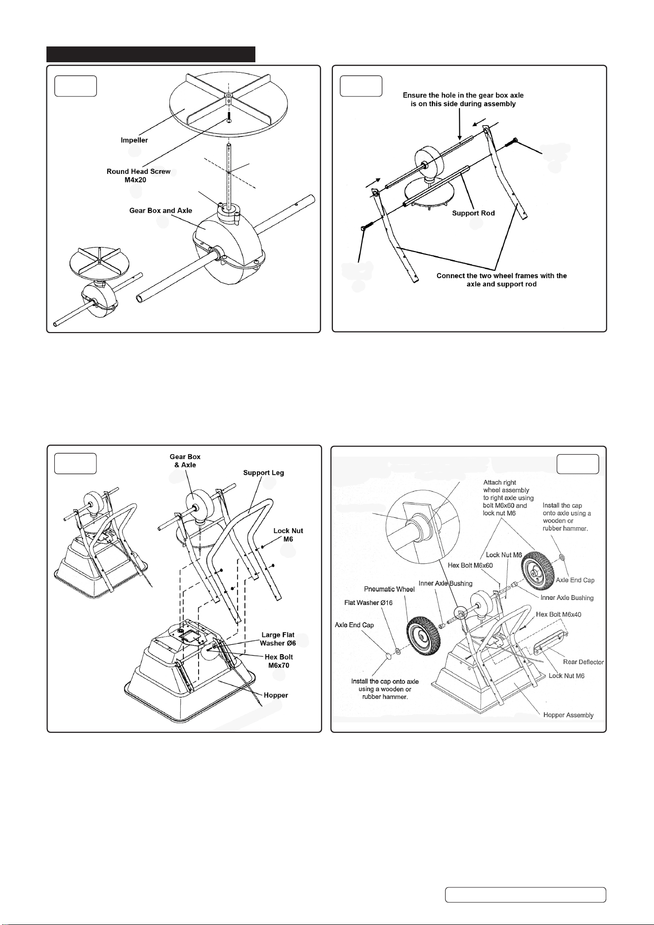
5. ASSEMBLY
NOTE: Before assembly ensure there are no missing parts or fixtures.
5.1. Refertog.1forttingtheimpeller.
5.1.1. Slide the Impeller (19), with vanes uppermost over the vertical axle on the gearbox (34). Align the hole in the impeller boss with the
lower pre-drilled hole in the spindle.
5.1.2. Secure the Impeller to the axle with a round head screw M4x20 (35). Ensure the impeller is secured to the lower hole on the vertical
axle.
5.2. Refertog.2forttingthewheelframes(forks).
5.2.1. Slidethewheelframes(27)and(18)overtheaxle,ensurethebushhousing(33)isfacinginwardsasing.5andg.6.
5.2.2. Secure with support rod (47) and M6x35 hex bolts (20).
5.3. Refertog.3forsupportlegandgearboxtting.
5.3.1. Take the hopper (11) and lay it upside down, lower the gearbox and frame onto the hopper, inserting the vertical axle through the
hopper and centre hub (13).
5.3.2. On top of the wheel frame, lay the support leg (26), secure together with hex bolts M6x70 (14) and large washer (41),
Inserting from inside the hopper securing with lock nuts (25) on the outside.
5.4. Refertog.4forundercarriageandreardeectortting.
5.4.1. Slidetheouteraxlebushes(33)overtheaxleandpushintotheframewithlocationlobeinnermost,seealsog.6.
5.4.2. Insert the inner axle bush (32) into the outer axle bush.
5.4.3. Fitthewheels(29).SecuretherighthandwheelusinghexboltM6x60(36)andalocknut(25);seeg.4andg.6forclarity.
5.4.4. Placeaatwasher(30)overtheendoftheaxleandthentheaxlecaps(31).Useasoftfacedmallettoensuretheaxlecapsare
seated correctly.
5.4.5. Attach the rear deflector (58) to the support leg; fasten with M6x40 hex bolts (24) and M6 lock nuts (25).
fig.
3
fig.
4
fig.
4
Flange of outer axle
bushing outermost with
the keyed lug innermost.
Inner axle bushing
and wheel spacer
outermost.
(34)
(26)
(25)
(14)
(41)
(11)
(38)
(31)
(30)
(29)
(32)
(36&25)
(24)
(25)
(33)
(32)
(58)
[Seealsog.6
forttingbushes]
fig.
2
fig.
1
(19)
(35)
(34)
(20)
(47)
(20)
(27)
(18)
(33)
(33)
(28)
Impeller
xing
point
Hex Bolt
M6x35
Hex Bolt
M6x35
SSB37W Issue 4 14/04/23
Original Language Version
© Jack Sealey Limited
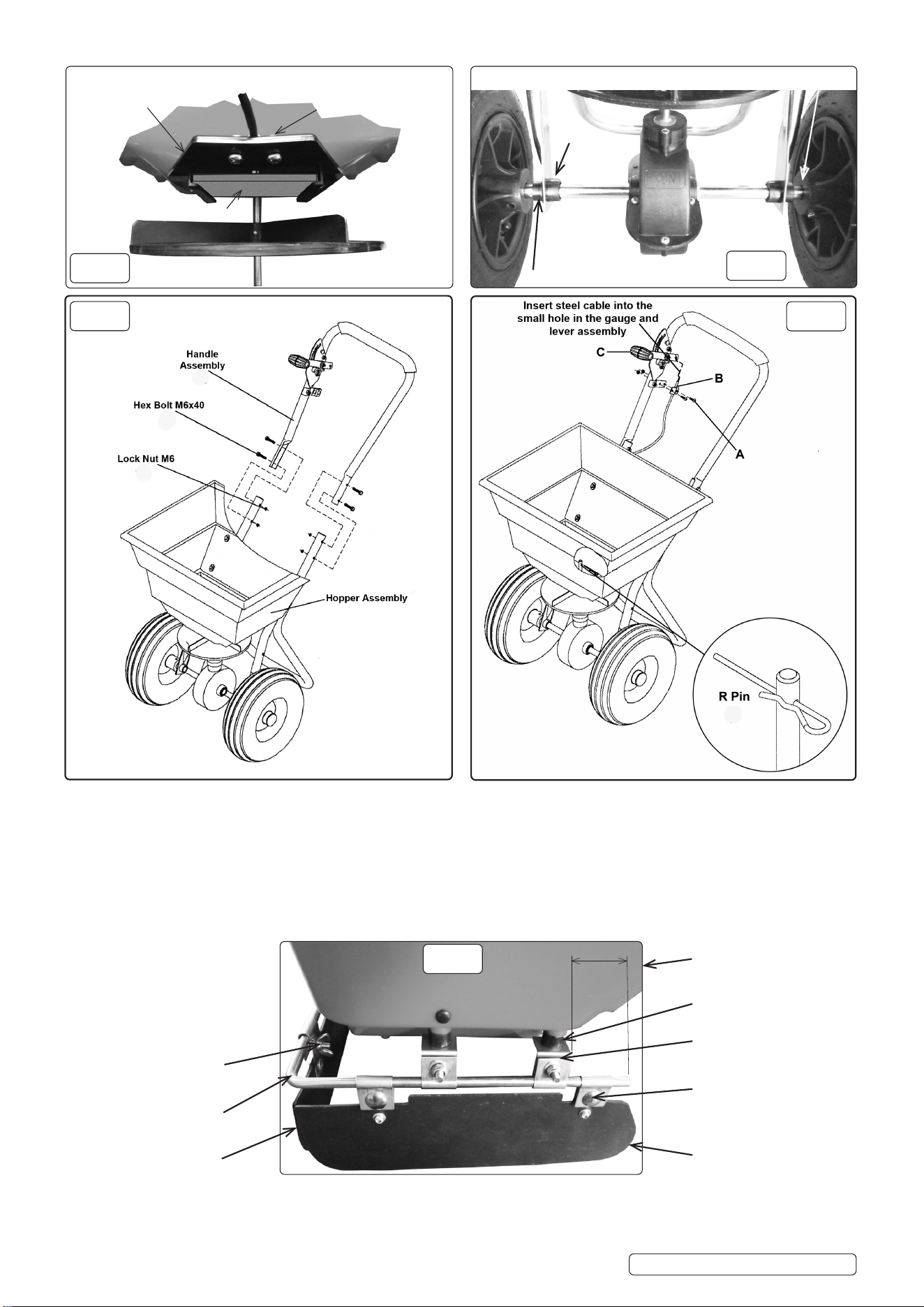
fig.
8
(35,25) Pinned hub this side
FRONT
(32)
fig.9
fig.7
Hopper
(9), (21), (59), (60)
(57)
(52)
(54)
(51)
(53, 56 opposite)
(55)
1st
2nd
55
(33)
Impeller (19)
Hopper (11)
(16)
(43)
(37),(17),(21)
Cable (38)
fig.
6
fig.
5
(42)
(24)
(25)
(39)
(37)&(38)
(4)&(5)&(6)
(12)
5.5. Refertog.7forhandletting.
5.5.1. Turn the spreader onto its wheels and slide the handle assembly (42) around the frame, secure with 4 M6x40 hex bolts (24) and
lock nuts (25).
5.6. Refertog.8forcontrolleverandcabletting.
5.6.1. Insert the bent end of the control cable (38) into the small hole in the lever assembly.
5.6.2. Remove the hex screws (17) from the cable clamp, then insert the control cable into the clamp (A,B).
5.6.3. Re-insert hex screws to clamp control cable in place.
5.6.4. Move the flow control lever (C) down to open the spreader slot in the bottom of the hopper. If the hole (fig.13) is not fully exposed or
fully closed, loosen the cable clamp (B) and adjust the cable.
5.6.5. Insert R-pin (12) through top of the vertical axle.
5.7. Refer to fig.9 for fitting front and side deflectors.
5.7.1. Offer the 4-M6 X 30 screws (60) from inside the hopper and fit 4 brackets (57) to underside of hopper with spacers (9) between.
5.7.2. Slide the boom rail (54) through the 1st clip in items (57) and (60), then brackets (57), finally the 2nd clip as indicated.
5.7.3. Clamp all 3 deflectors with wing nuts (51) and carriage bolts (52).
SSB37W Issue 4 14/04/23
Original Language Version
© Jack Sealey Limited
6. OPERATION
6.1. Priortollingthehopperwithsalt/grit,ensurethehopperscreen(49)isinsitu.Thiswillgradethesalt/gritpassingthroughtothe
throat plate and help prevent possible clogging.
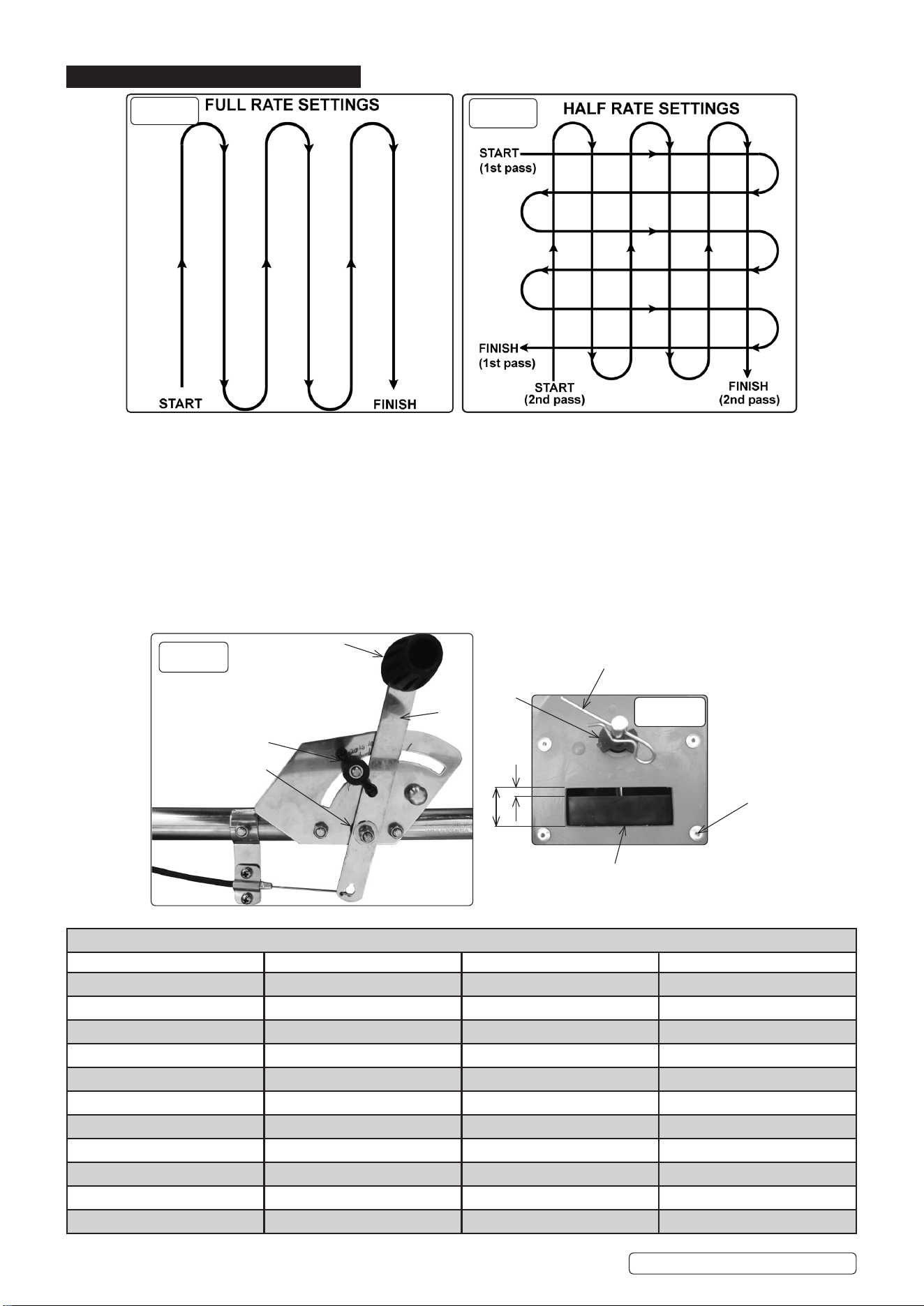
6.2. Usethestoponthegaugetoensurethesameamountofdistribution(g.12).
6.3. Seegs.10&11forsuggestedwalkingpatternsdependingonthelevelofcoverageyourequire.
6.4. Alwaysstartwalkingpriortoopeningtheowcontrollever.
6.5. Everytimeyouarereadytostop,orturntomakeanewpass,closetheowcontrollevertostopdispensingthematerialand
continue one more stride. This reduces waste with over saturated product coverage. Ensure the stop bolt continues to register
the spreader setting from table "B". Remembertostartwalkingpriortoopeningtheowcontrollever.
6.6. To ensure consistent coverage, make sure each broadcast pattern slightly overlaps the previous one.
6.7. Makesurethatanybroadcastmaterialdoesnotcomeintocontactwithtrees,shrubsandowersthatcouldbeharmedbythe
material.
6.8. Clean the spreader thoroughly after each use paying particular attention to the throat plate and the bottom of the hopper.
(CHART'A')SQUAREFOOTCOVERAGEPERBAG(LBS/1000SQ.FT)
WEIGHTOFBAG(LBS) 5000SQ.FTCOVERAGE 10000SQ.FTCOVERAGE 15000SQ.FTCOVERAGE
5 1.0lb 0.5lb 0.3lb
10 2.0lb 1.0lb 0.7lb
15 3.0lb 1.5lb 1.0lb
20 4.0lb 2.0lb 1.3lb
25 5.0lb 2.5lb 1.7lb
30 6.0lb 3.0lb 2.0lb
35 7.0lb 3.5lb 2.3lb
40 8.0lb 4.0lb 2.3lb
45 9.0lb 4.5lb 3.0lb
50 10.0lb 5.0lb 3.3lb
55 11.0lb 5.5lb 3.7lb
fig.
10
fig.
11
fig.
12
"Usethestoponthegaugetoensure
the same amount of distribution"
Fullow
Setow
Adjustable Throat plate
Spinning agitator
fig.13
(10),(9),(1),(2)
(4)
(43)
(12)
(20),(40),(41),(25)
(13)
(15)
(5),(6),(7)
SSB37W Issue 4 14/04/23
Original Language Version
© Jack Sealey Limited

(CHART'B')SPREADERSETTINGS/SPREADERWIDTHS
MATERIALS TO BE
USED
LBS/1000
SQ.FT
G/M² SPREADER
SETTING
SMALL PARTICLE
SPREAD
MEDIUM PARTICLE
SPREAD
LARGE PARTICLE
SPREAD
GRIT
SEED
FERTILISER
WEED
KILLER
E.T.C.
1 5 5 5-6 ft 6-9 ft 9-12 ft
2 10 8 5-6 ft 6-9 ft 9-12 ft
3 15 10 5-6 ft 6-9 ft 9-12 ft
4 20 13 5-6 ft 6-9 ft 9-12 ft
5 25 15 5-6 ft 6-9 ft 9-12 ft
6 30 18 5-6 ft 6-9 ft 9-12 ft
7 35 20 5-6 ft 6-9 ft 9-12 ft
8 40 23 5-6 ft 6-9 ft 9-12 ft
9 45 25 5-6 ft 6-9 ft 9-12 ft
10 50 28 5-6 ft 6-9 ft 9-12 ft
11 55 30 5-6 ft 6-9 ft 9-12 ft
6.9. CALCULATINGTHEAMOUNTOFMATERIALNEEDED.(refertoCharts'A'&'B')
6.10. The spreader is designed to be pushed at three miles an hour, which is a brisk walking pace. Slower or faster speeds will change
thespreadpattern.Wetsalt/gritwillalsochangethespreadpattern.Seeg.13formediaagitator;promotingow.
6.11. To calculate the amount of salt/grit needed, divide the coverage stated on the packaging by the weight of the bag.
6.12. For example, a 10lb bag of salt/grit with a coverage of 10,000 sq.ft. will distribute 1lb of salt/grit every 1,000 sq.ft. at full rate or
1/2lb. of salt/grit every 1,000 sq.ft. at half rate.
6.13. For pre-calculated rates see Chart'A' (Example: A 25lb bag with a 15,000 sq.ft. coverage requires 1.7lb of media per 1,000 sq.ft.
6.14. Use Chart'B'tondtheclosestspreadersetting.Forexample,1.7lbper1000sq.ft.=spreadersetting6)
6.15. Use both charts as a guide only; experience will replace necessity to use the charts but they will be a good reference point.
7. MAINTENANCE
7.1. After each use clean material out of hopper.
7.2. Rinse/dry inside and outside of spreader after each use.
7.3. Beforeoperatingmakesurethatthetyresareinatedtothecorrectpressurei.e.25psimaximum.
7.4. Periodically check all fastenings are tight.
7.5. Check the condition of the "media agitator" (12) "R" pin, after continued use. Replace if required.
7.6. Annually clean and lightly lubricate cable.
7.7. To avoid damaging the spreader never exceed the rated load capacity of 37kg.
7.8. Usetheraincover(48)whennecessary.Avoidusingthespreaderwhenraining,unlessessential.
7.9. Beforestoringensurethatthespreaderiscleananddry;ttheraincover.
7.10. Store indoors or in a protected area during severe weather and in the winter months.
NOTE: DO NOT allow material to stay in the hopper for extended periods of time.
Sealey Group, Kempson Way, Suffolk Business Park, Bury St Edmunds, Suffolk. IP32 7AR
01284757500 sales@sealey.co.uk www.sealey.co.uk
ENVIRONMENTPROTECTION
Recycle unwanted materials instead of disposing of them as waste. All tools, accessories and packaging should be
sorted, taken to a recycling centre and disposed of in a manner which is compatible with the environment. When
the product becomes completely unserviceable and requires disposal, drain any fluids (if applicable) into approved
containers and dispose of the product and fluids according to local regulations.
Note: It is our policy to continually improve products and as such we reserve the right to alter data, specifications and component parts without
prior notice. Please note that other versions of this product are available. If you require documentation for alternative versions, please email
or call our technical team on technical@sealey.co.uk or 01284 757505.
Important: No Liability is accepted for incorrect use of this product.
Warranty: Guarantee is 12 months from purchase date, proof of which is required for any claim.
SSB37W Issue 4 14/04/23
Original Language Version
© Jack Sealey Limited