
Pelco Fisheye Installation Manual
C6710M | 12/21
2
Table of Contents
Important Safety Information 4
Regulatory Notices 4
Legal Notices 5
Overview 7
IMF82/IMF122 — Surface Mount 7
Cover View 7
Internal View 8
Bottom View 9
Wall Plate Adapter View 10
IMF82/IMF122 — In-Ceiling Mount 11
Cover View 11
Internal View 12
In-Ceiling Mount View 13
IMF-PM — Pendant Mount 14
NPT Adapter View 14
WMVE-AW Wall Mount View 15
Preparing the Installation 15
Pre-Deployment In-Box Configuration 15
Removing the Fisheye Cover 16
Mounting and Aiming Video Analytics Cameras 17
Preparing the Cables 17
Inserting an Ethernet Cable through the Single-Hole Grommet 18
Inserting Cables through the 3-Hole Grommet 18
Surface Mount Installation 19
Required Tools and Materials 19
Camera Package Contents 19
Installation Steps 20
Mounting in the Correct Orientation 20
Mounting the Camera to a Ceiling or Wall 21
Mounting the Camera Using the Side Conduit Entry Hole 23
Mounting the Camera to an Electrical Box 26
Connecting Cables 30
Installing the Fisheye Cover 31
In-Ceiling Mount Installation 32
Required Tools and Materials 32
Camera Package Contents 32
Installation Steps 32
Mounting in the Correct Orientation 33
Using the In-Ceiling Mounting Adapter 34
Installing the Camera Base into the Mounting Adapter 37
Connecting Cables 40

Pelco Fisheye Installation Manual
C6710M | 12/21
3
Installing the In-Ceiling Cover
41
Pendant Mount Installation 42
Required Tools and Materials 42
Camera Package Contents 42
Installation Steps 42
Mounting the Camera to the WMVE Wall Mount 42
Installing the Camera into the NPT Adapter 43
Connecting Cables 46
Installing the Fisheye Cover 47
Connecting to the Camera 49
Initializing a Camera Username and Password 49
Assigning an IP Address 49
Accessing the Live VideoStream 49
(Optional) Configuring Onboard Storage 49
(Optional) Enabling the Microphone 50
Configuring the Microphone 50
Configuring the Camera 51
For More Information 51
Cable Connections 51
Connecting External Power 51
Connecting to External Audio and I/O Devices 51
Connection Status LED Indicator 52
Troubleshooting Network Connections and LED Behavior 52
Resetting to Factory Default Settings 53
Setting the IP Address Using the ARP/Ping Method 54
Cleaning 54
Dome Bubble 54
Body 54
Pelco Fisheye Installation Manual
C6710M | 12/21
4
Important Safety Information
This manual provides installation and operation information and precautions for the use of this device.
Incorrect installation could cause an unexpected fault. Before installing this equipment read this manual
carefully. Please provide this manual to the owner of the equipment for future reference.
Warning:This symbol indicates the presence of dangerous voltage within and outside the
product enclosure that may result in a risk of electric shock, serious injury or death to
persons if proper precautions are not followed.
Caution: This symbol alerts the user to the presence of hazards that may cause minor or moderate
injury to persons, damage to property or damage to the product itself if proper precautions are not
followed.
Warning: Failure to observe the following instructions may result in severe injury or death.
l Installation must be performed by qualified personnel only, and must conform to all local codes.
l This product is intended to be supplied by a UL Listed Power Unit marked “Class 2” or “LPS” or
“Limited Power Source” with output rated 12 VDC, 11 W min. (26 W min. with -IR model) or PoE, 11
W min. (26 W min. with -IR model).
l Do not connect directly to mains power for any reason.
Warning: Failure to observe the following instructions may result in injury to persons or damage to
the device.
l Do not expose the camera directly to high levels of x-ray, laser, or UV radiation. Direct exposure
may cause permanent damage to the image sensor.
l Do not install near any heat sources such as radiators, heat registers, stoves, or other sources of
heat.
l Do not subject the device cables to excessive stress, heavy loads or pinching.
l Do not open or disassemble the device. There are no user serviceable parts.
l Refer all device servicing to qualified personnel. Servicing may be required when the device has
been damaged (such as from a liquid spill or fallen objects), has been exposed to rain or moisture,
does not operate normally, or has been dropped.
l Do not use strong or abrasive detergents when cleaning the device body.
l Use only accessories recommended by Pelco.
l This product should be installed in restricted access locations.
Regulatory Notices
This device complies with part 15 of the FCC Rules. Operation is subject to the following two conditions:
(1)this device may not cause harmful interference, and (2) this device must accept any interference
received, including interference that may cause undesired operation.
This Class B digital apparatus complies with Canadian ICES-003.
This equipment has been tested and found to comply with the limits for a Class B digital device, pursuant to
Part 15 of the FCC rules. These limits are designed to provide reasonable protection against harmful
interference in a residential installation. This equipment generates, uses and can radiate radio frequency
Pelco Fisheye Installation Manual
C6710M | 12/21
5
energy and, if not installed and used in accordance with the instructions, may cause harmful interference to
radio communications. However, there is no guarantee that interference will not occur in a particular
installation. If this equipment does cause harmful interference to radio or television reception, which can be
determined by turning the equipment off and on, the user is encouraged to try to correct the interference by
one or more of the following measures:
l Reorient or relocate the receiving antenna.
l Increase the separation between the equipment and the receiver.
l Connect the equipment into an outlet on a circuit different from that to which the receiver is
connected.
l Consult the dealer or an experienced radio/TV technician for help.
Changes or modifications made to this equipment not expressly approved by Pelco Corporation or parties
authorized by Pelco Corporation could void the user’s authority to operate this equipment.
Disposal and Recycling Information
When this product has reached the end of its useful life, please dispose of it according to your local
environmental laws and guidelines.
Risk of fire, explosion, and burns. Do not disassemble, crush, heat above 100 °C (212 °F), or incinerate.
European Union:
This symbol means that according to local laws and regulations your product should be disposed of
separately from household waste. When this product reaches its end of life, take it to a collection point
designated by local authorities. Some collection points accept products for free. The separate collection
and recycling of your product at the time of disposal will help conserve natural resources and ensure that it
is recycled in a manner that protects human health and the environment.
Legal Notices
© 2021,Pelco Corporation. All rights reserved. PELCO, the PELCO logo, PELCO are trademarks of
Pelco Corporation. ONVIFis a trademark of Onvif, Inc. Other names or logos mentioned herein may be the
trademarks of their respective owners. The absence of the symbols ™ and ® in proximity to each
trademark in this document or at all is not a disclaimer of ownership of the related trademark. Pelco
Corporation protects its innovations with patents issued in the United States of America and other
jurisdictions worldwide (see www.pelco.com). Unless stated explicitly and in writing, no license is granted
with respect to any copyright, industrial design, trademark, patent or other intellectual property rights of
Pelco Corporation or its licensors.
Disclaimer
This document has been compiled and published using product descriptions and specifications available at
the time of publication. The contents of this document and the specifications of the products discussed
herein are subject to change without notice. Pelco Corporation reserves the right to make any such
changes without notice. Neither Pelco Corporation nor any of its affiliated companies: (1) guarantees the
completeness or accuracy of the information contained in this document; or (2) is responsible for your use
of, or reliance on, the information. Pelco Corporation shall not be responsible for any losses or damages
(including consequential damages) caused by reliance on the information presented herein.
Pelco Corporation
www.pelco.com

Pelco Fisheye Installation Manual
C6710M | 12/21
6
PDF-H5AFE-A
Revision: 1 - EN
20211210
Pelco Fisheye Installation Manual
C6710M | 12/21
7
Overview
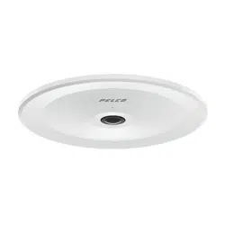
IMF82/IMF122 — Surface Mount
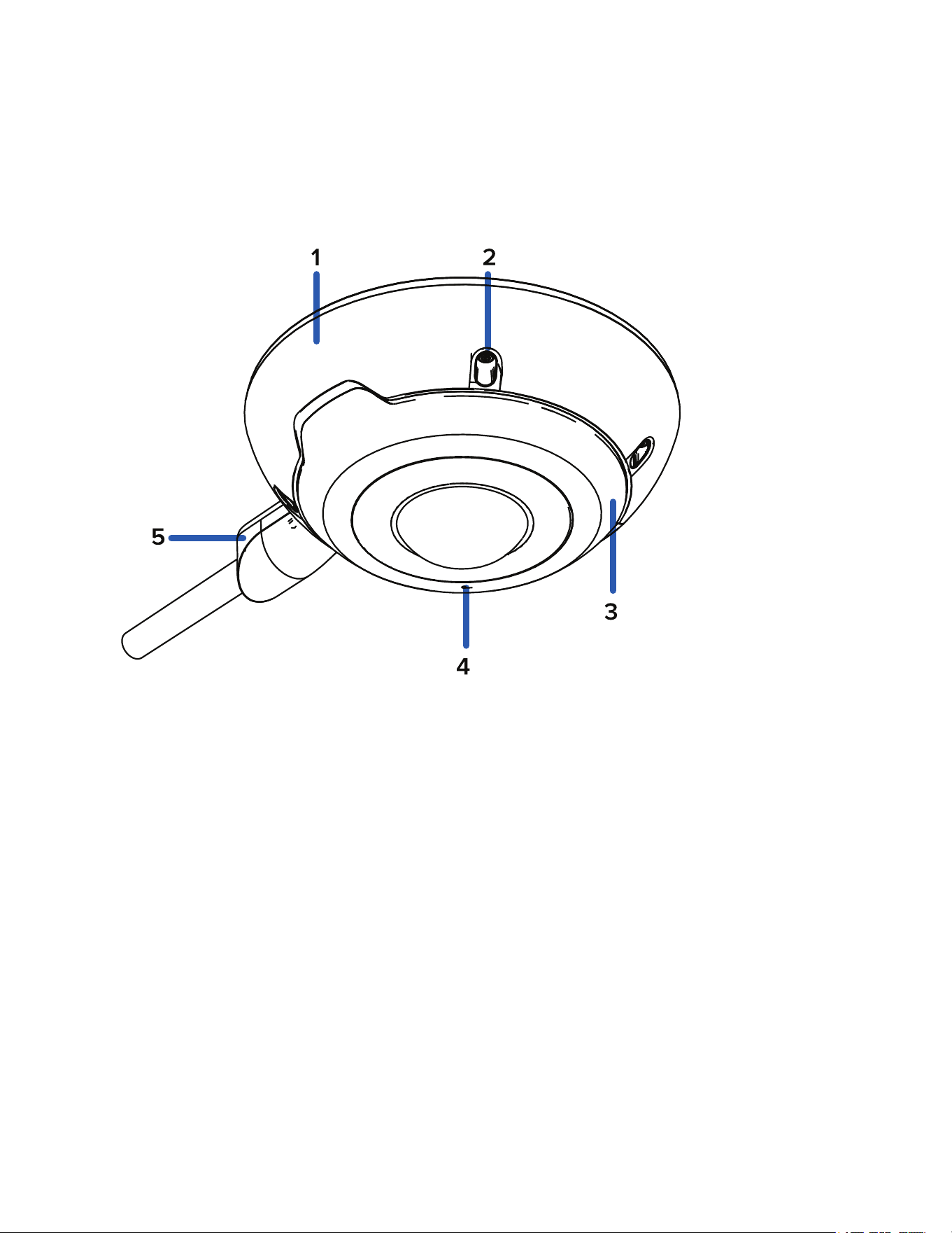
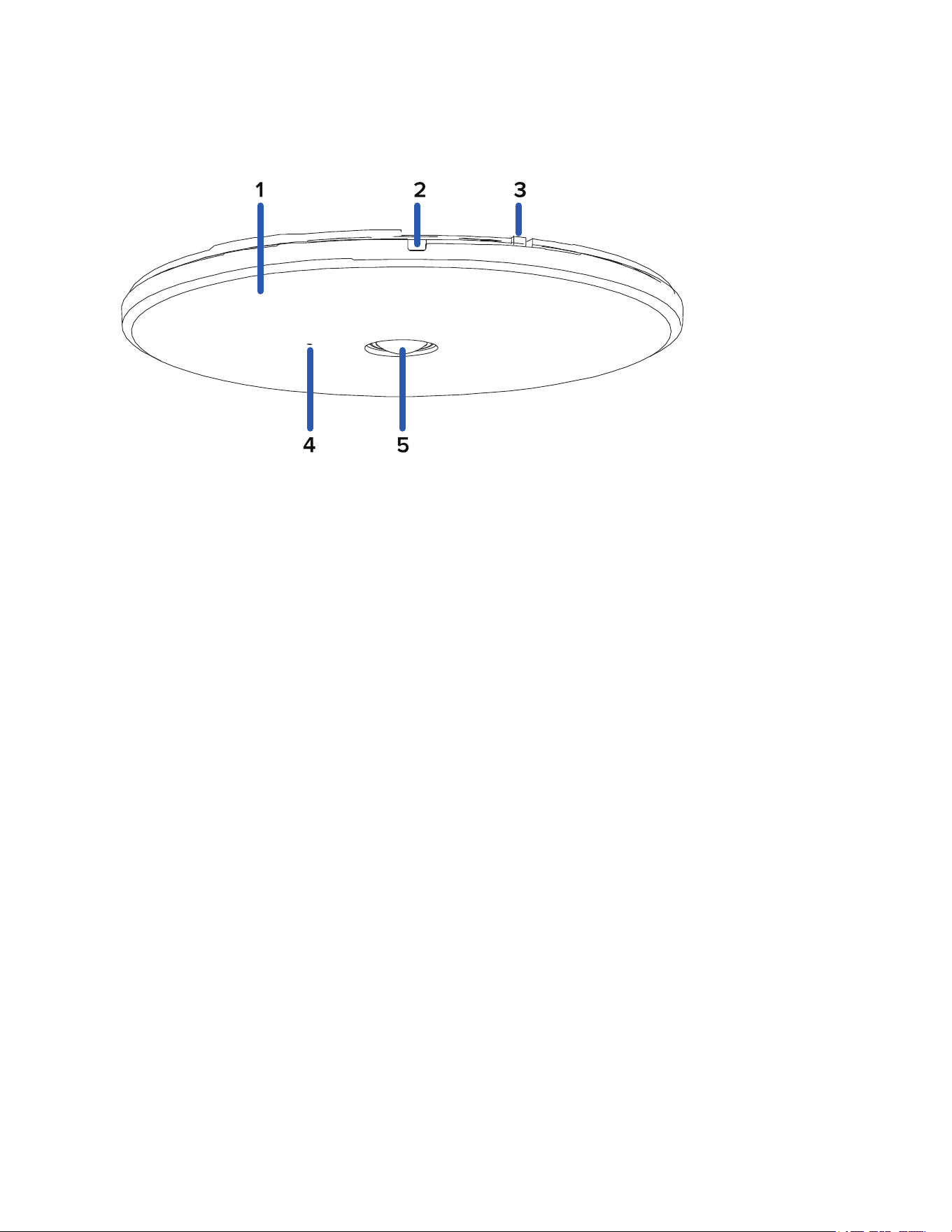
Cover View
1. Dome cover
Vandal resistant dome cover.
2. Tamper resistant screws
Star-shaped captive screws to fix the dome cover to the base.
3. IR illuminator
Provides scene illumination in the IR spectrum for supported camera models.
4. Microphone
Built-in audio receiver.
5. Conduit shroud
Optional shroud for connecting a side-entry 1/2" (18 mm) EMT conduit for cabling.
Pelco Fisheye Installation Manual
C6710M | 12/21
8
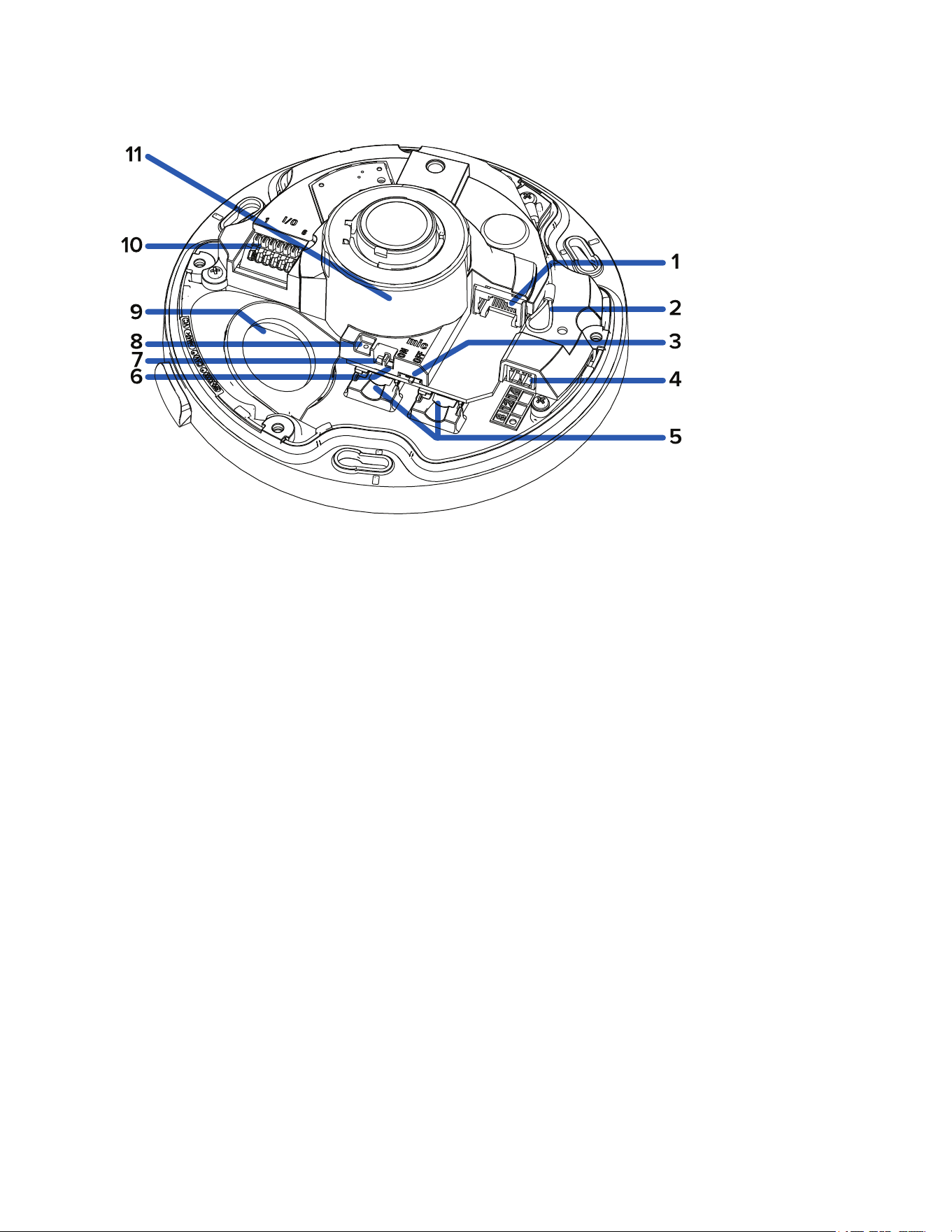
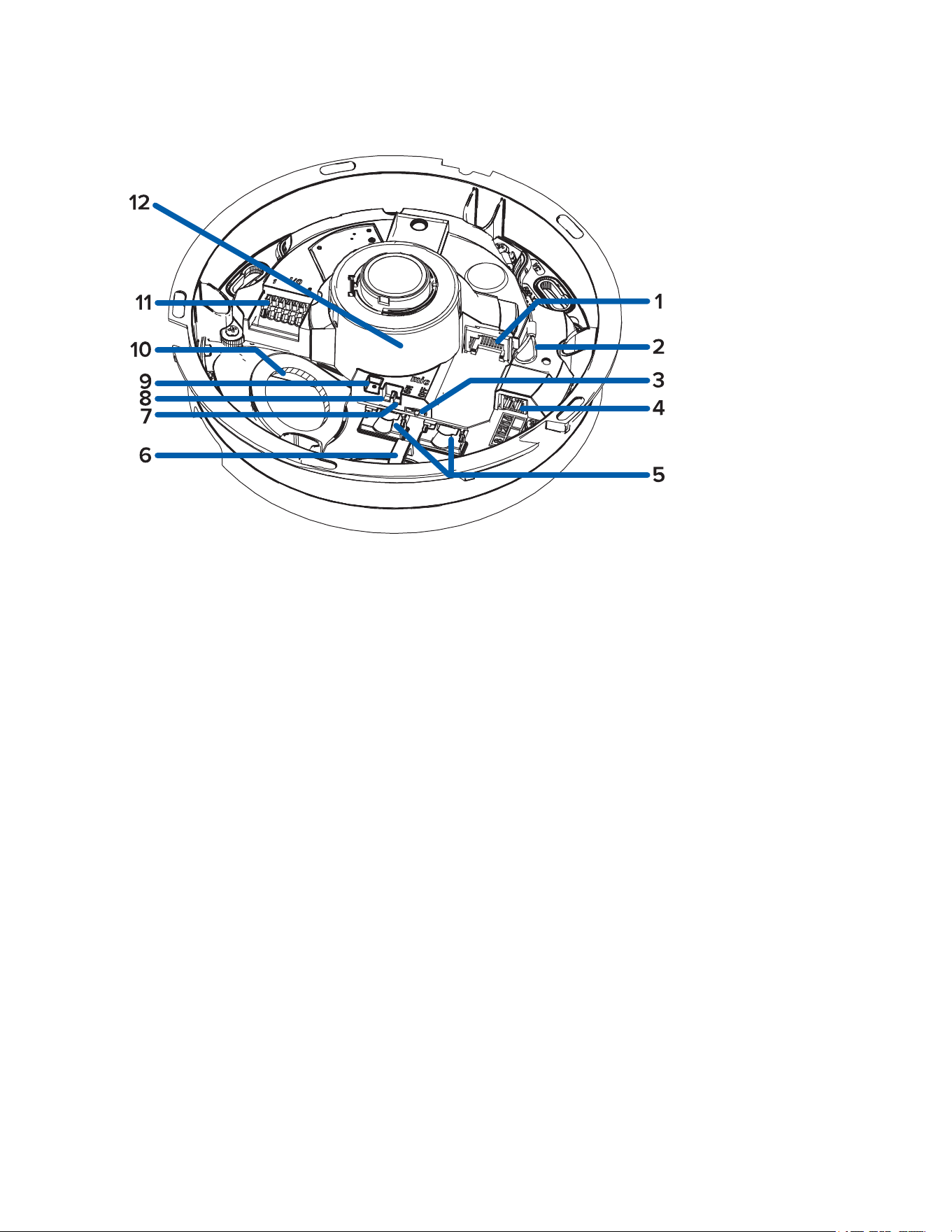
Internal View
1. Ethernet port
Accepts an Ethernet connection to a network. Server communication and image data transmission
occurs over this connection. Also receives power when it is connected to a network that provides
Power over Ethernet.
2. Lanyard
Anchors the cover to the camera base.
3. Microphone switch
Switch to enable or disable the built-in microphone. For more information, see (Optional) Enabling
the Microphone.
4. Power connector block
Accepts an external DC power connection when Power over Ethernet is not available.
5. microSD card slots (x2)
Accepts up to two microSD cards for onboard storage. Install microSD cards so the metal contacts
are facing upward. For more information, see (Optional) Configuring Onboard Storage.
6. Connection status LED indicator
Green LED provides information about device operation. For more information, see Connection
Status LED Indicator.
7. Link LED indicator
Amber LED indicates if there is an active connection in the Ethernet port.
8. Firmware revert button
Resets the camera to its factory default settings.
9. Cable entry hole
Pelco Fisheye Installation Manual
C6710M | 12/21
9
An entry hole for the cables required for camera operation.
10. I/O connector block
Provides connections to external input/output and audio devices.
11. Serial number tag
Device information, product serial number and part number label.
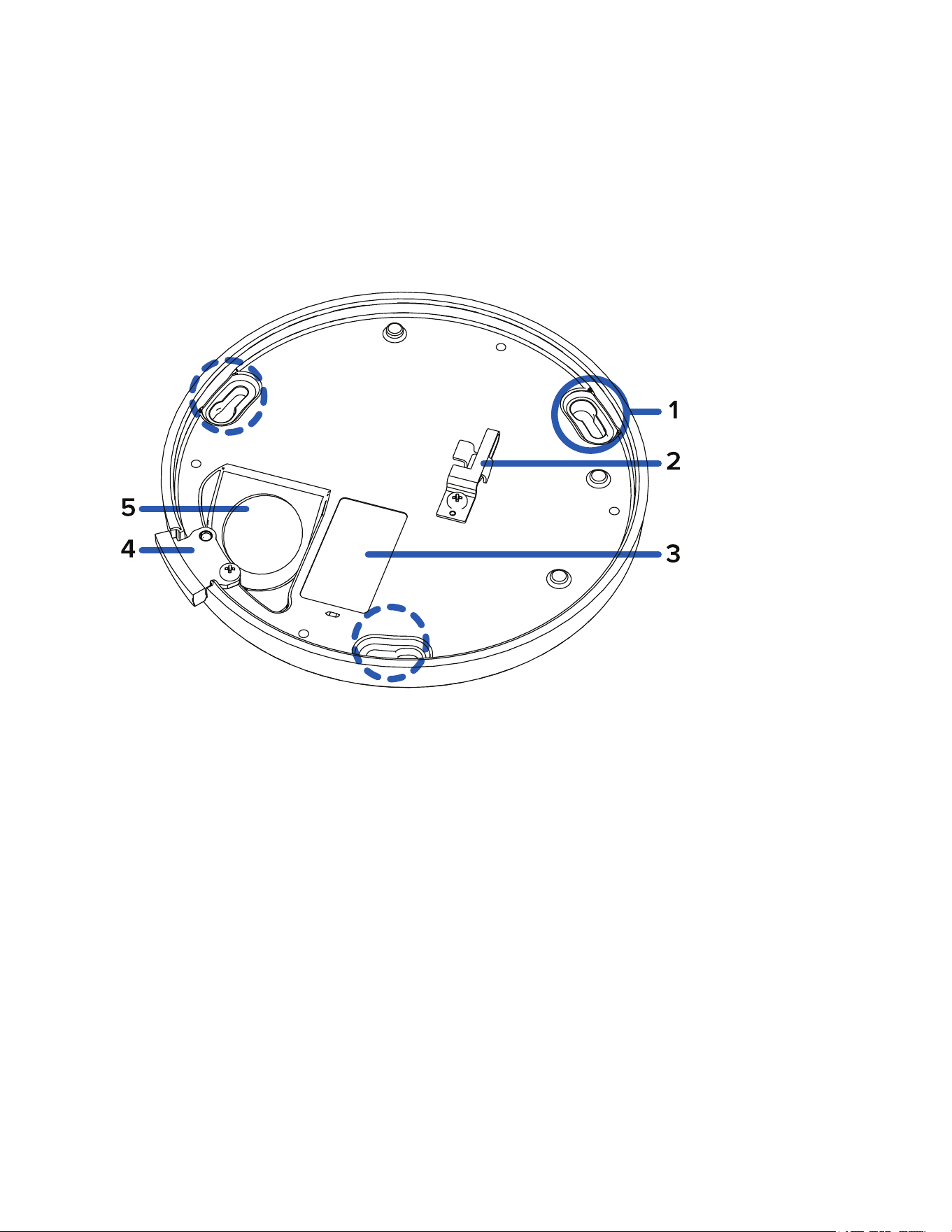
Bottom View
1. Mounting slots
The mounting points for the camera.
If using the optional electrical box wall plate adapter or NPT adapter, align the mounting posts with
the mounting slots.
If mounting directly to a wall or ceiling, insert the mountings screws through the slots to fix the
camera to the mounting surface.
2. Lanyard anchor
The safety lanyard attaches to the anchor to prevent the camera from falling during installation.
3. Serial number tag
Device information, product serial number and part number label.
4. Side conduit tab
For installations that require cabling through a side conduit, this tab should be removed and replaced
by the conduit shroud.
5. Cable entry hole
An entry hole for the cables required for camera operation.
Pelco Fisheye Installation Manual
C6710M | 12/21
10
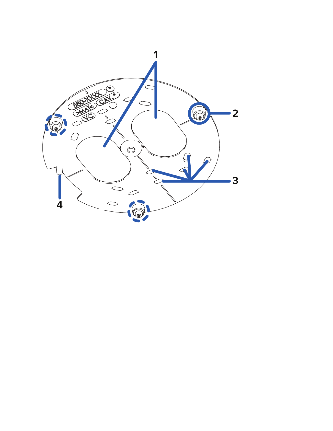
Wall Plate Adapter View
1. Cable entry holes
Entry holes for the cables required for camera operation.
2. Camera mounting posts
Align the mounting posts on the wall plate adapter to the mounting slots on the camera base.
3. Mounting holes
Holes for mounting the wall plate to the following:
l UK standard single gang box
l Octagon gang box
l 4" gang box
l Mounting surface
l US standard single gang box
4. Orientation post
Orientation post that fits properly into the cable entry hole area of the camera base. Post will prevent
installation in the incorrect orientation.
Pelco Fisheye Installation Manual
C6710M | 12/21
11
IMF82/IMF122 — In-Ceiling Mount
Cover View
1. In-ceiling cover
Discreet cover, which can be painted to blend into the mounting surface.
2. Cover lock
Locking point for securing the cover to the in-ceiling mount.
3. Mount lock
Locking point that the cover clicks into to secure the cover in place.
4. Microphone
Built-in audio receiver.
5. Camera lens
Fisheye camera lens.
Pelco Fisheye Installation Manual
C6710M | 12/21
12
Internal View
1. Ethernet port
Accepts an Ethernet connection to a network. Server communication and image data transmission
occurs over this connection. Also receives power when it is connected to a network that provides
Power over Ethernet.
2. Lanyard
Anchors the cover to the camera base.
3. Microphone switch
Switch to enable or disable the built-in microphone. For more information, see (Optional) Enabling
the Microphone.
4. Power connector block
Accepts an external DC power connection when Power over Ethernet is not available.
5. microSD card slots (x2)
Accepts up to two microSD cards for onboard storage. Install microSD cards so the metal contacts
are facing upward. For more information, see (Optional) Configuring Onboard Storage.
6. Ethernet cable clip
Clip to secure the Ethernet cable out of the way of other camera components.
7. Connection status LED indicator
Green LED provides information about device operation. For more information, see Connection
Status LED Indicator.
8. Link LED indicator
Amber LED indicates if there is an active connection in the Ethernet port.
Pelco Fisheye Installation Manual
C6710M | 12/21
13
9. Firmware revert button
Resets the camera to its factory default settings.
10. Cable entry hole
An entry hole for the cables required for camera operation.
11. I/O connector block
Provides connections to external input/output and audio devices.
12. Serial number tag
Device information, product serial number and part number label.
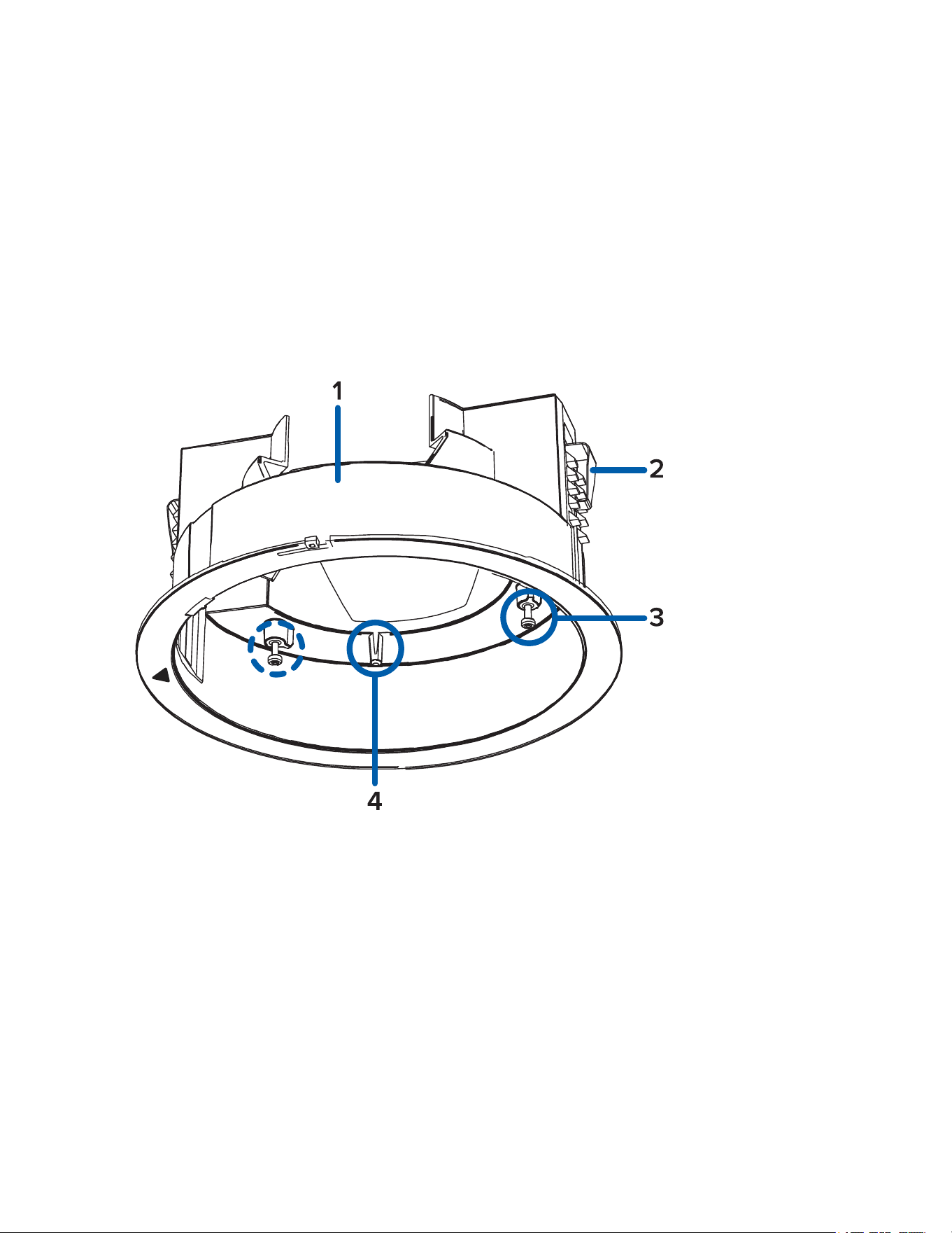
In-Ceiling Mount View
1. In-ceiling mount adapter
Used to mount the camera to a ceiling.
2. Clamps
Manually adjustable clamps for securing the camera to the ceiling.
3. Camera mounting posts
Align the mounting posts on the in-ceiling adapter to the mounting slots on the camera base.
4. Orientation post
Orientation post that fits properly into the cable entry hole area of the camera base. Post will prevent
installation in the incorrect orientation.
Pelco Fisheye Installation Manual
C6710M | 12/21
14
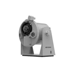
IMF-PM — Pendant Mount
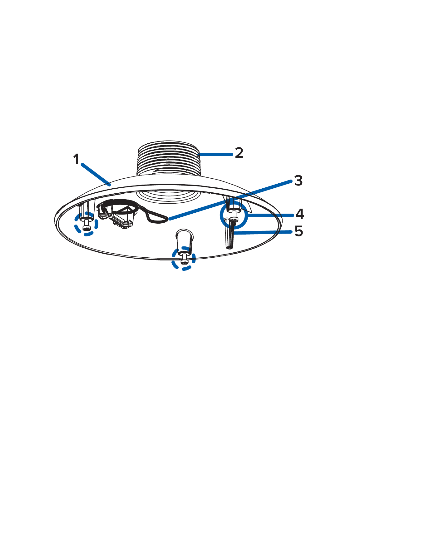
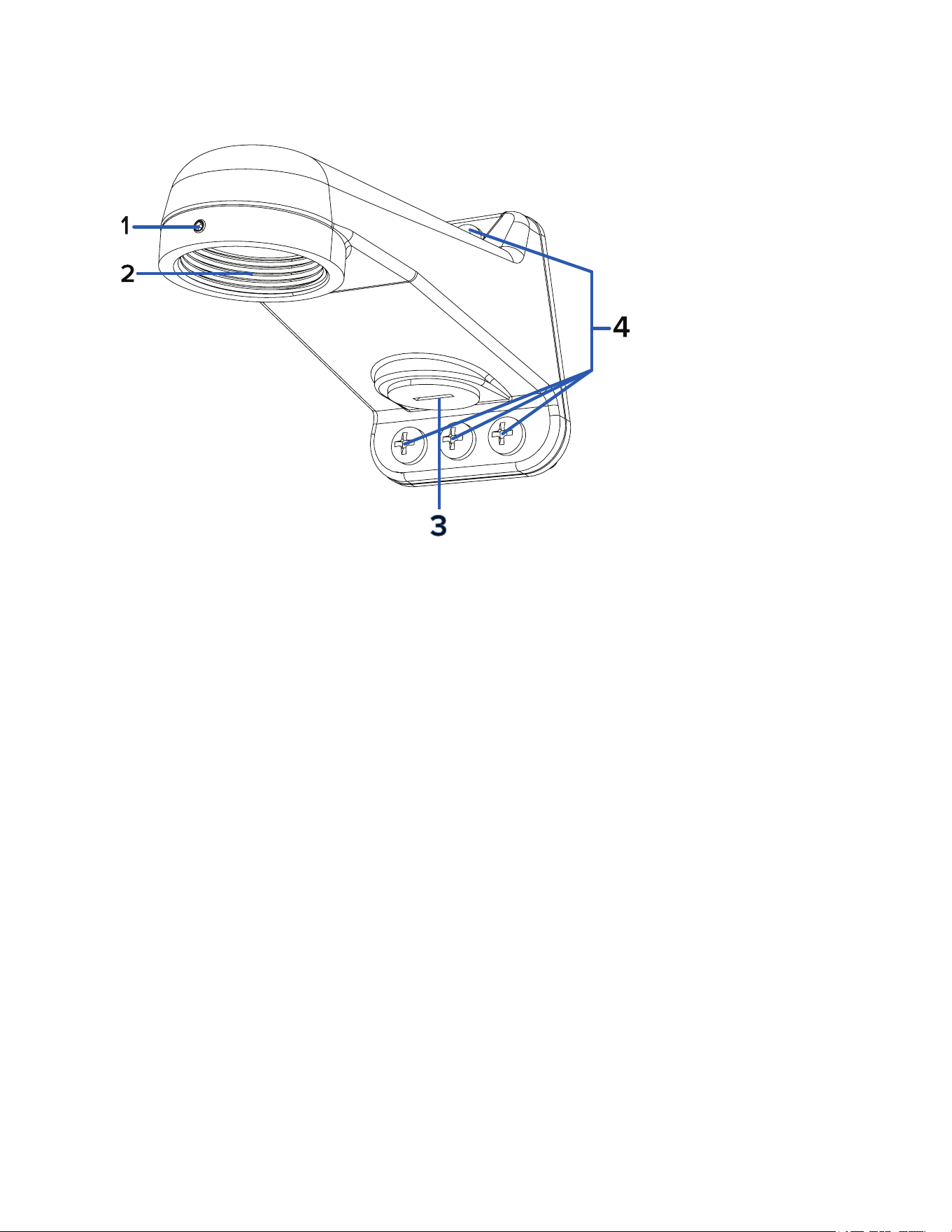
NPT Adapter View
1. Pendant NPT adapter
Camera pendant mount adapter for NPT pipes and wall arm installations.
2. 1-1/2” NPT thread mount
Standard female 1-1/2” NPT thread mount for mounting the camera to an NPT pipe or wall arm.
3. Lanyard
Connects to the lanyard anchor on the camera base.
4. Camera mounting posts
Align the mounting posts on the pendant NPT adapter to the mounting slots on the camera base.
5. Orientation post
Orientation post that fits properly into the cable entry hole area of the camera base. Post will prevent
installation in the incorrect orientation.
Pelco Fisheye Installation Manual
C6710M | 12/21
15
WMVE-AW Wall Mount View
1. Set screw
A 5/64" set screw for securing the pendant adapter thread.
2. 1-1/2” NPT thread mount
Female NPS thread mount for pendant camera installations.
3. NPT pipe entry hole
A 3/4" NPT threaded hole for NPT pipe conduits
4. Pendant wall mount screws
Screws for securing the pendant wall mount to the mounting surface.
Preparing the Installation
Pre-Deployment In-Box Configuration
The camera comes equipped with an RJ45 configuration cable pre-installed for users that want to configure
camera settings before installing the camera. The RJ45 connector on the configuration cable is accessible
through the small flap on the side of the camera box for easy configuration before unpacking the camera.
We recommend that you do not exceed 3 hours of leaving your camera connected during in-box
configuration with ambient temperatures between 20 °C – 25 °C (68 °F – 77 °F).
1. Locate and open the flap on the side of the camera packaging.
2. Connect a network cable to the RJ45 plug on the configuration cable. The network cable must
provide PoE. IEEE 802.3af Class 3, to power the camera during configuration.
3. Connect to the camera using a video management system, the Camera Configuration Tool, or the
camera's web browser interface to configure the camera's settings. For more information about
connecting to the camera, see Assigning an IP Address, and Accessing the Live VideoStream.
4. Once you have finished making configuration changes, unplug the network cable.
Pelco Fisheye Installation Manual
C6710M | 12/21
16
Warning: Be careful when handling the camera after configuring it inside the packaging. The camera
may be hot when handling it or removing from the packaging immediately after in-box configuration.
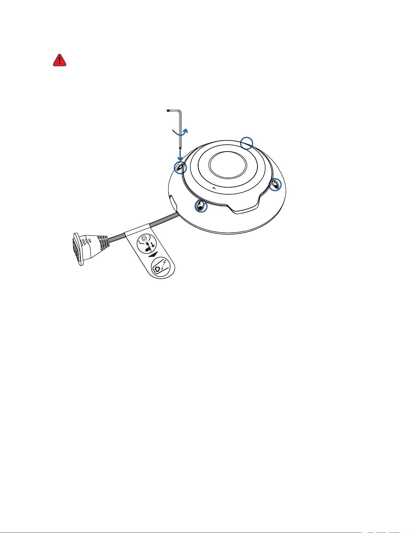
Removing the Fisheye Cover
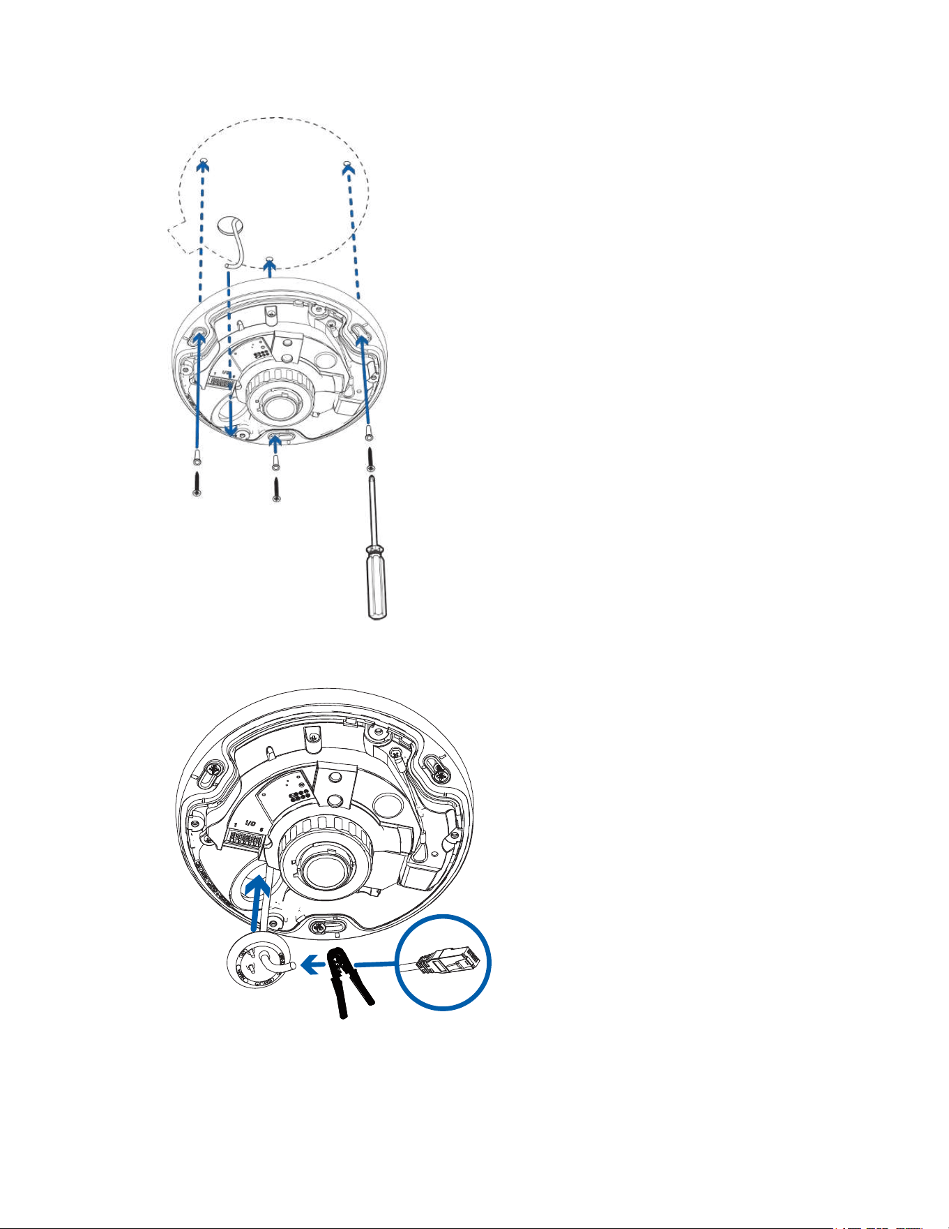
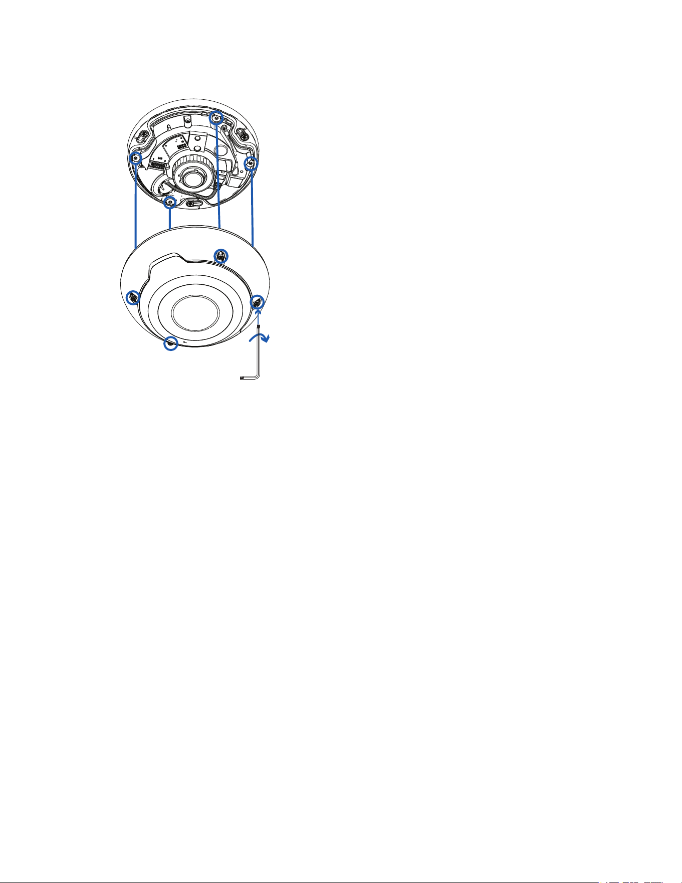
1. Remove the cover by loosening the screws that fix the cover to the base. Use the provided star-
shaped screwdriver to loosen the screws.
x4
Be careful not to scratch or touch the dome bubble. The resulting marks or fingerprints may affect
the overall image quality. Keep the protective covers on the outside of the dome bubble until the
installation is complete.
2. Lift the cover off the camera base and set it aside.
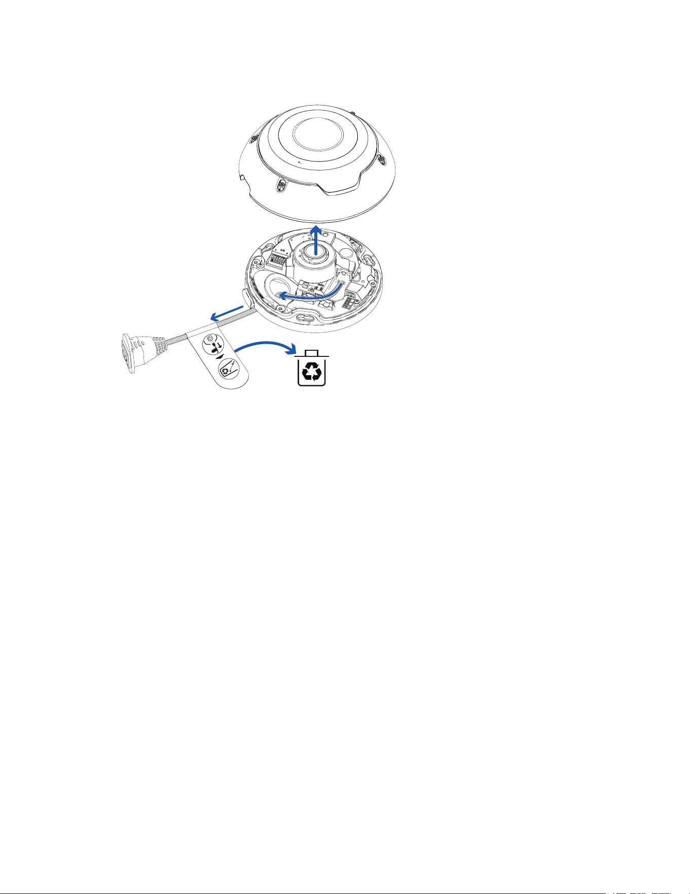
Pelco Fisheye Installation Manual
C6710M | 12/21
17
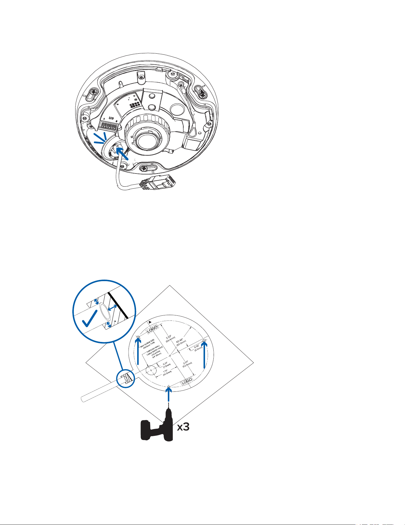
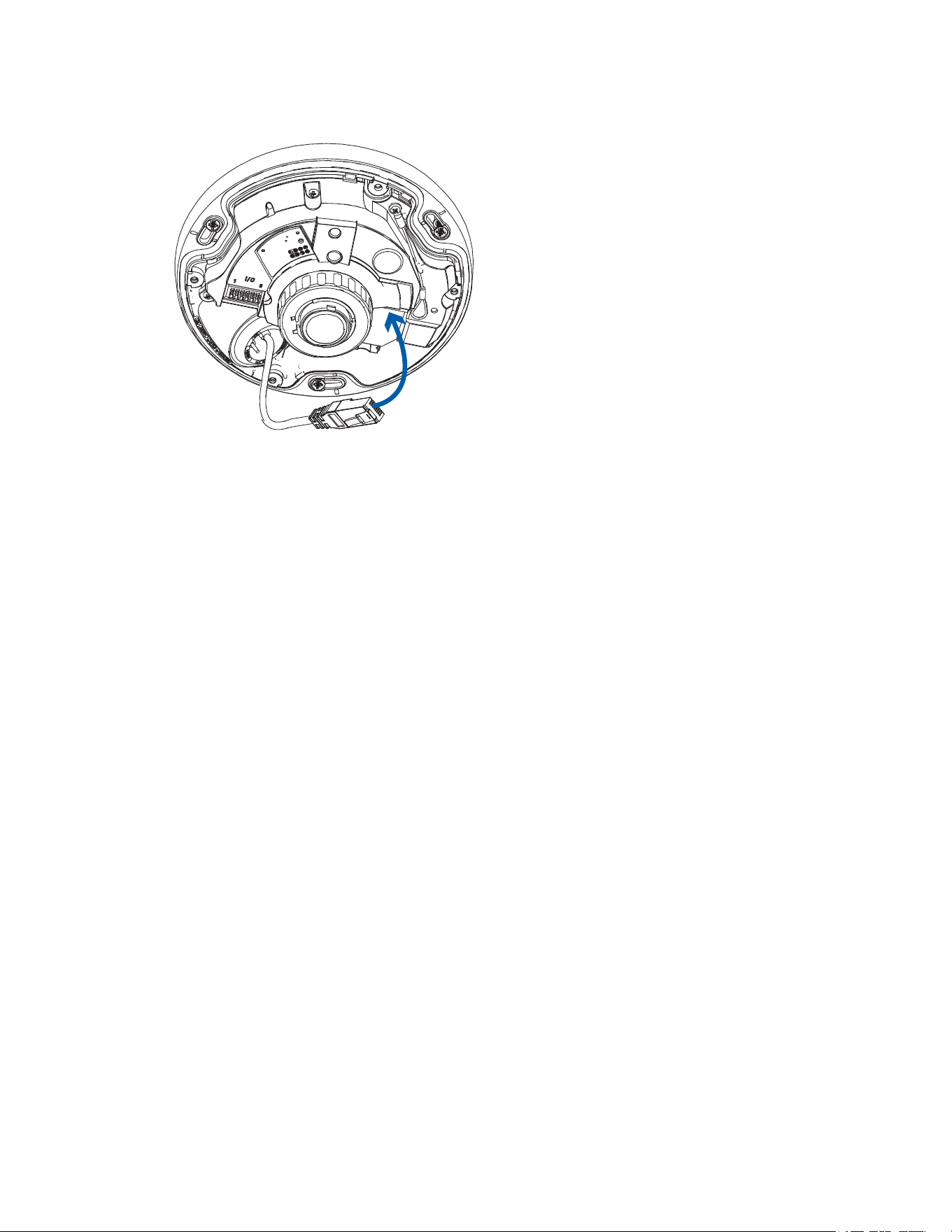
3. Unplug and remove the RJ45 in-box configuration cable that comes pre-installed on the camera.
Mounting and Aiming Video Analytics Cameras
When installing an Pelco IMF Fisheye video analytics camera, follow the listed mounting and aiming
recommendations to maximize the camera's analytics capabilities:
l The camera should be mounted on a ceiling and look down on the scene.
Video analytics are not currently supported when the IMF Fisheye camera is mounted on a wall and
looking horizontally at the scene.
l We recommend installing the camera above 2.74 m (9 feet).
l The camera should be installed parallel to the floor.
l The camera should be mounted to a stable surface to minimize the physical movement of the
camera after installation.
For more details, see Designing a Site for Video Analytics. The document is available on the Pelco
website.
Preparing the Cables
Before you connect the cables to the camera, you must prepare the cables for installation.
If the camera is installed outdoors, it is important that the cables be insulated against the weather. Provided
with the camera are two rubber grommets for waterproofing the required cables:
l Use the single-hole rubber grommet for installations using PoE power and require only the Ethernet
cable. For more information, see Preparing the Cables.
l Use the 3-hole rubber grommet for installations that require more than one cable. For more
information, see Preparing the Cables.
Pelco Fisheye Installation Manual
C6710M | 12/21
18
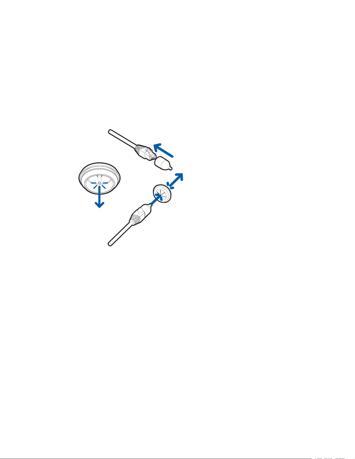
Inserting an Ethernet Cable through the Single-Hole Grommet
You must pull the required Ethernet cable through the single-hole sealing grommet included with the
camera.
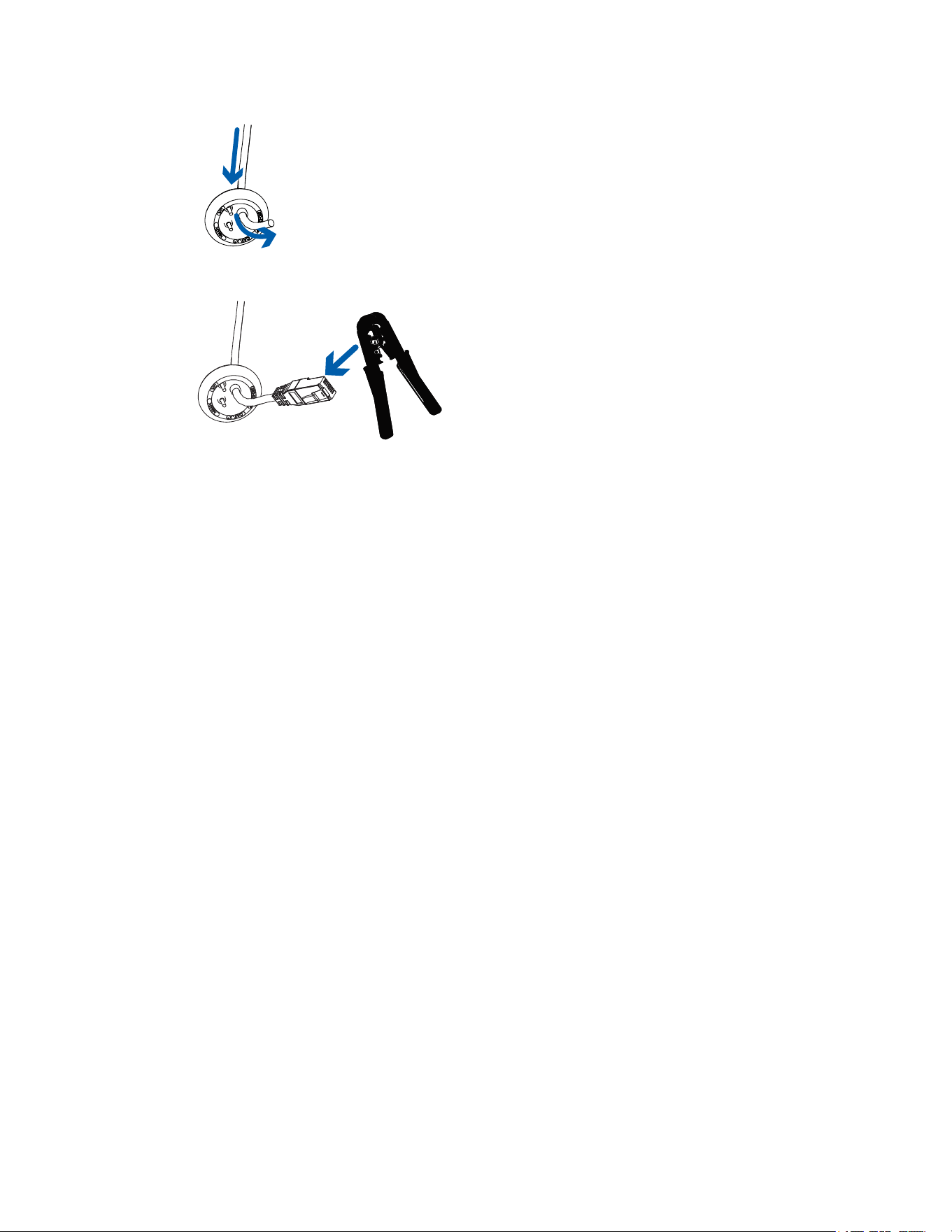
1. Remove the sealing grommet from the accessory kit.
2. Pull the tab on the grommet to open a hole for the Ethernet cable.
3. Push an Ethernet cable through the grommet by one of the following methods:
a. If the Ethernet cable is uncrimped, push the cable through the grommet.
b. If the Ethernet cable is already crimped, place the grommet piercing cap on the Ethernet
connector then push the cable through the grommet.
Ensure that the orientation of the cable and grommet matches the one shown in the image.
c. If you require multiple cables, see Preparing the Cables to follow the 3-hole grommet
procedure.
Inserting Cables through the 3-Hole Grommet
The Ethernet cable must be uncrimped to perform this procedure.
The camera includes an I/O terminal for input/output and audio connections, an external power connector,
and an Ethernet connector. If you are connecting 2 or more cables to the camera, follow this procedure for
using the 3-hole sealing grommet to insulate the cables from the weather.
1. Remove the sealing grommet from the accessory kit.
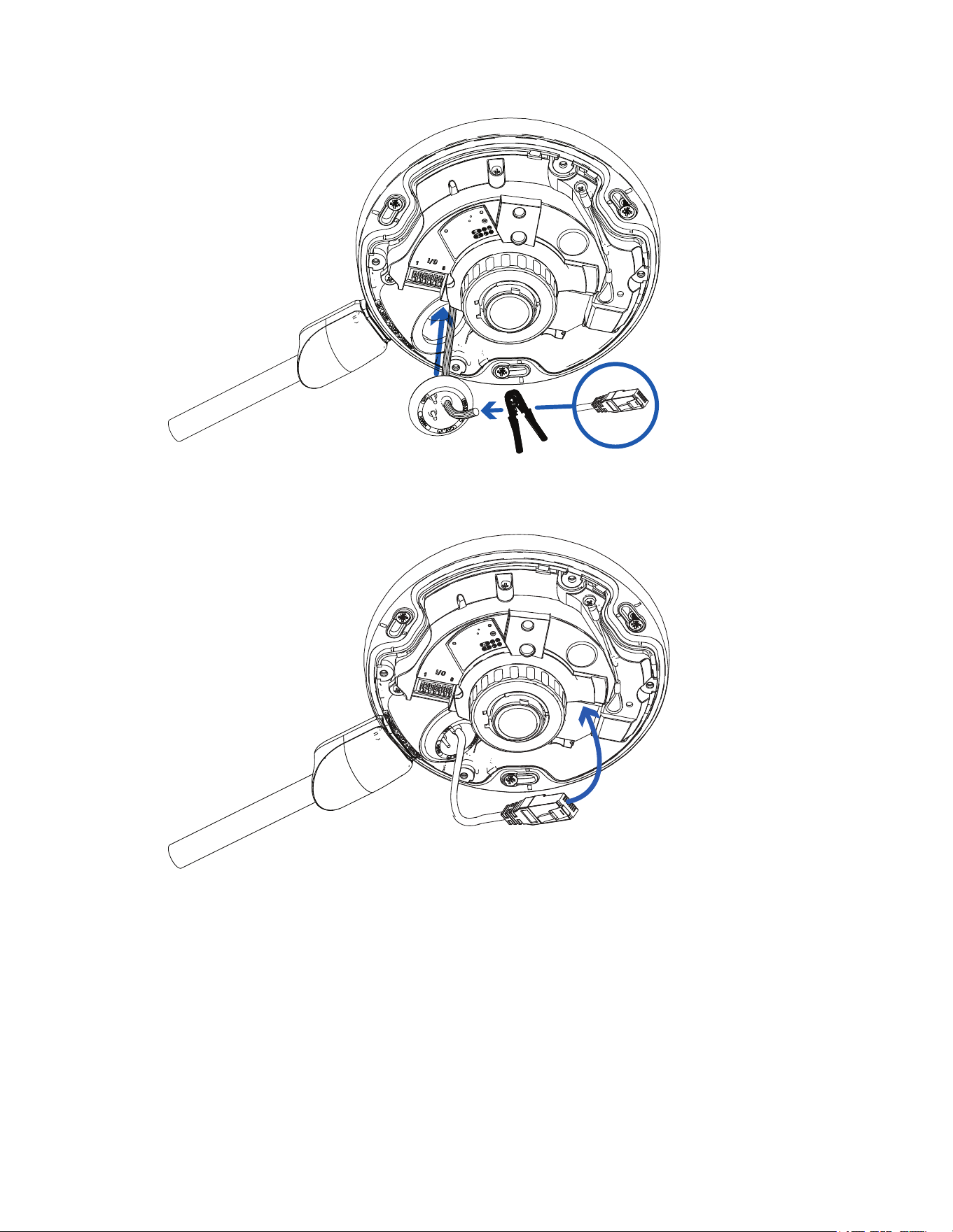
2. Thread the Ethernet cable into the largest hole in the 3-hole rubber grommet.
a. Push the Ethernet cable through the open hole in the rubber grommet.
Ensure the orientation of the cable and grommet matches the following image.
Pelco Fisheye Installation Manual
C6710M | 12/21
19
b. Crimp the connector onto the Ethernet cable.
3. If you are using other cables, pull one or both of the tabs on the grommet to open the secondary
holes for the additional cables.
4. Thread the additional cables through the secondary grommet holes.
Threading thin cables through the secondary holes may require the use of silicone sealant at the
opening to ensure weather proofing.
5. Do not connect the cables to the camera until indicated in the installation procedure.
Surface Mount Installation
Required Tools and Materials
The following tools are required to complete the installation but are not included in the package:
l Appropriate tool for cutting the cable access hole
l Small slotted screwdriver with 5/64” or 2 mm blade width — for connecting power when not using
Power over Ethernet
l No. 2 Phillips screwdriver — for attaching camera to an electrical box or mounting surface
Camera Package Contents
Ensure the surface mounted camera package contains the following:
l Pelco IMF Fisheye Camera
l Camera Base Mounting Template sticker
l Optional wall plate adapter — for electrical box installations.
l Star-shaped screwdriver
l Power terminal block
l Optional conduit shroud — for side-entry conduit cabling.
l 3x screws and anchors — for securing the camera to the mounting surface.
Pelco Fisheye Installation Manual
C6710M | 12/21
20
l 3-hole rubber grommet — for multi-cable installations.
l Single-hole rubber grommet — for installations with a single Ethernet/PoE cable.
l RJ45 grommet piercing cap — for use with single-hole rubber grommet only.
Installation Steps
Complete the following sections to install the device.
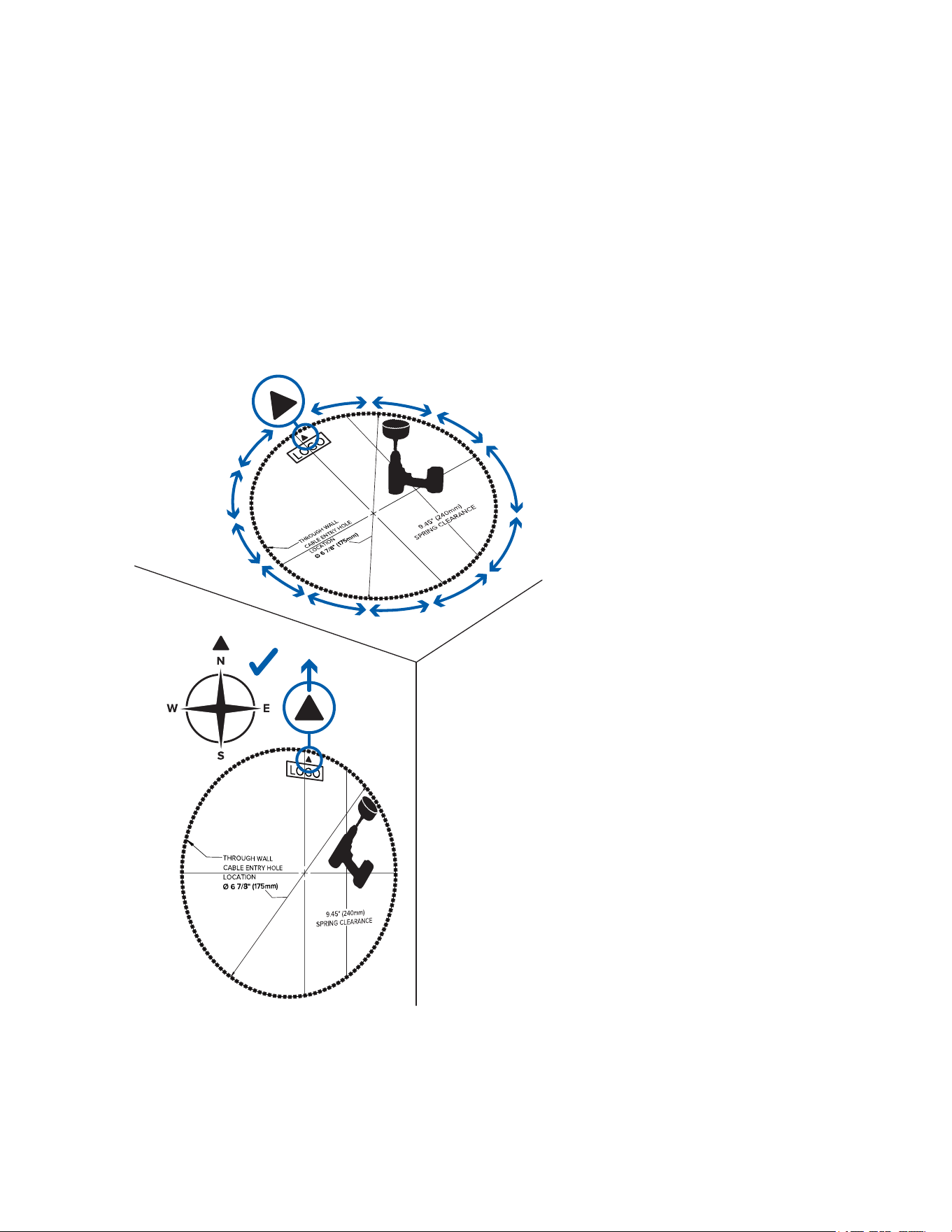
Mounting in the Correct Orientation
The IMF Fisheye camera provides 360° views of large areas. Because of the 360° view, it is not obvious
which part of the camera should be facing up when installed on a wall. To help with this, the mounting
template and the camera body have an up orientation arrow printed on them to signal which end should be
facing up.
When installing the camera on a ceiling, the orientation arrow can go in any direction.
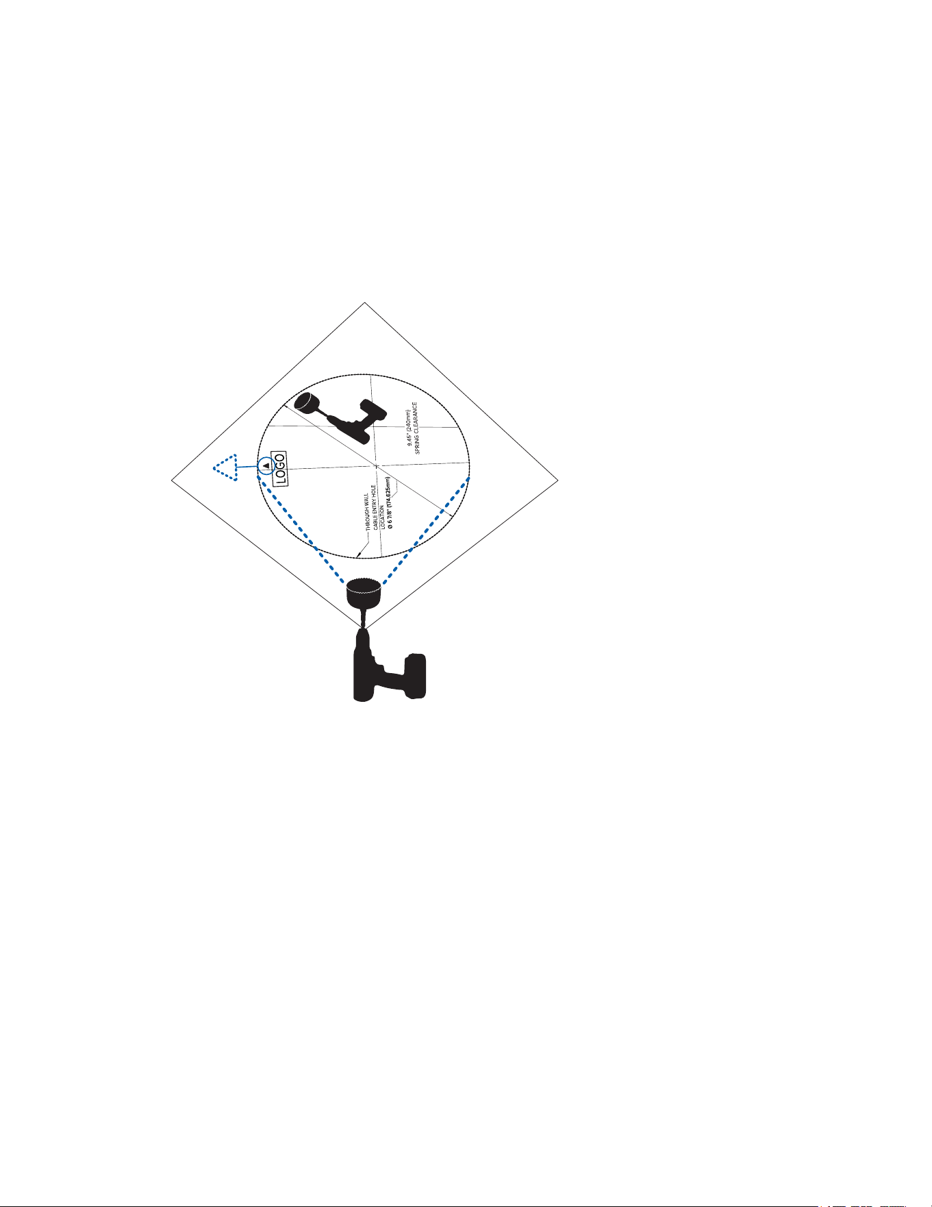
Before removing the mounting template after cutting or drilling the required holes, mark or otherwise make
note of the direction the orientation arrow is facing. This will help you to align the camera body in the same
orientation when installing.
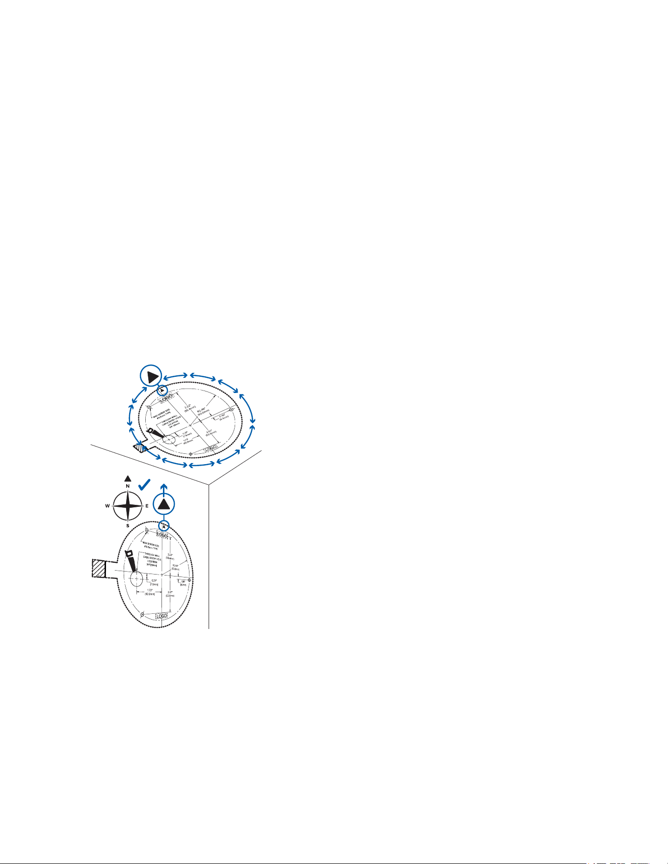
When installing the camera to a wall, make sure that the orientation arrow is facing up, as shown in the
diagram below.
Pelco Fisheye Installation Manual
C6710M | 12/21
21
Mounting the Camera to a Ceiling or Wall
Perform the following steps if the required cables will be coming from inside the mounting surface and the
camera will be mounted immediately over the cable hole. Use this procedure on surfaces that can be easily
drilled into, and when the cables should be kept out of sight.
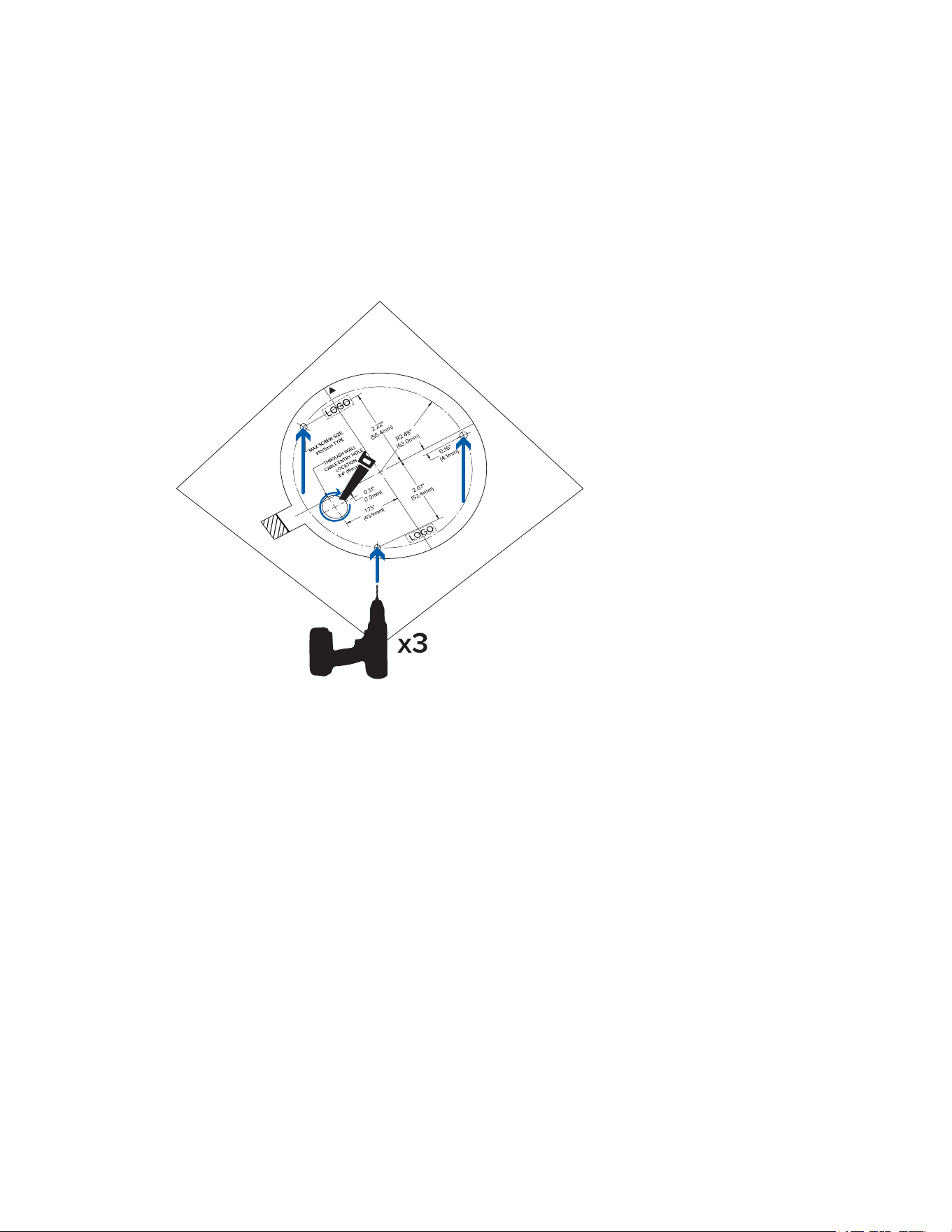
1. Using the Surface Mounting Template, drill 3 pilot holes into the mounting surface for the mounting
screws.
If you are mounting the camera to a wall, make sure the up orientation arrow is at the top, or the
video image will be rotated. For more information, see Mounting in the Correct Orientation.
2. Hammer the supplied plastic anchors into the holes.
3. Drill the cable entry hole into the mounting surface.
4. Pull the required cables through the mounting surface and through the cable entry hole in the camera
base.
5. Align the up orientation arrow on the camera base with the arrow on the mounting template. Align the
mounting slots on the camera base to the drilled pilot holes and use the provided self-tapping screws
to secure the camera to the mounting surface.
Pelco Fisheye Installation Manual
C6710M | 12/21
22
6. Pull the required cables through the rubber sealing grommet. For more information, see Preparing
the Cables.
7. Push the rubber sealing grommet with the required cables into the cable entry hole on the camera
base. The thread around the grommet should line up with the cable entry hole.
The rubber grommet should be pressed firmly into the cable entry hole to create a seal.
Pelco Fisheye Installation Manual
C6710M | 12/21
23
Mounting the Camera Using the Side Conduit Entry Hole
Perform the following steps if the required cables will be run along the mounting surface. Use this
procedure if the mounting surface is difficult to drill into, or if the cables must be routed outside of the
mounting surface.
1. Using the Surface Mounting Template, drill 3 pilot holes into the mounting surface for the mounting
screws.
If you are mounting the camera to a wall, make sure the up orientation arrow is at the top, or the
video image will be rotated. For more information, see Mounting in the Correct Orientation.
Pelco Fisheye Installation Manual
C6710M | 12/21
24
2. Align the conduit for the cables so that the end of the conduit falls inside the conduit landing area of
the mounting template.
3. Hammer the supplied plastic anchors into the holes.
4. Arrange and feed the required cables through the conduit.
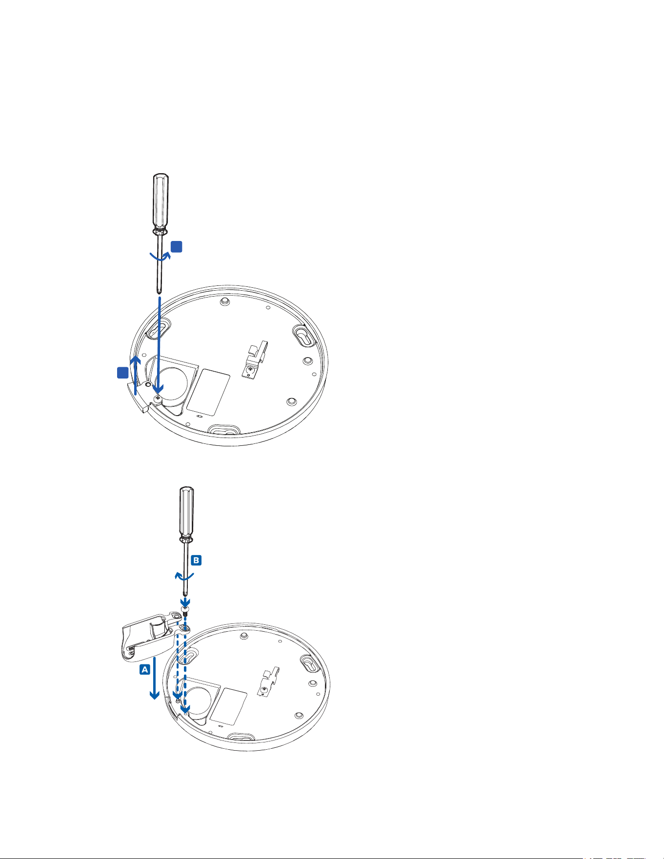
5. Loosen the screw holding the cable entry tab on the side of the camera base. Remove the cable
entry tab.
A
B
6. Use the same screw to install the optional conduit shroud to the cable entry tab position. The
conduit shroud is compatible with up to 1/2" conduits.
Pelco Fisheye Installation Manual
C6710M | 12/21
25
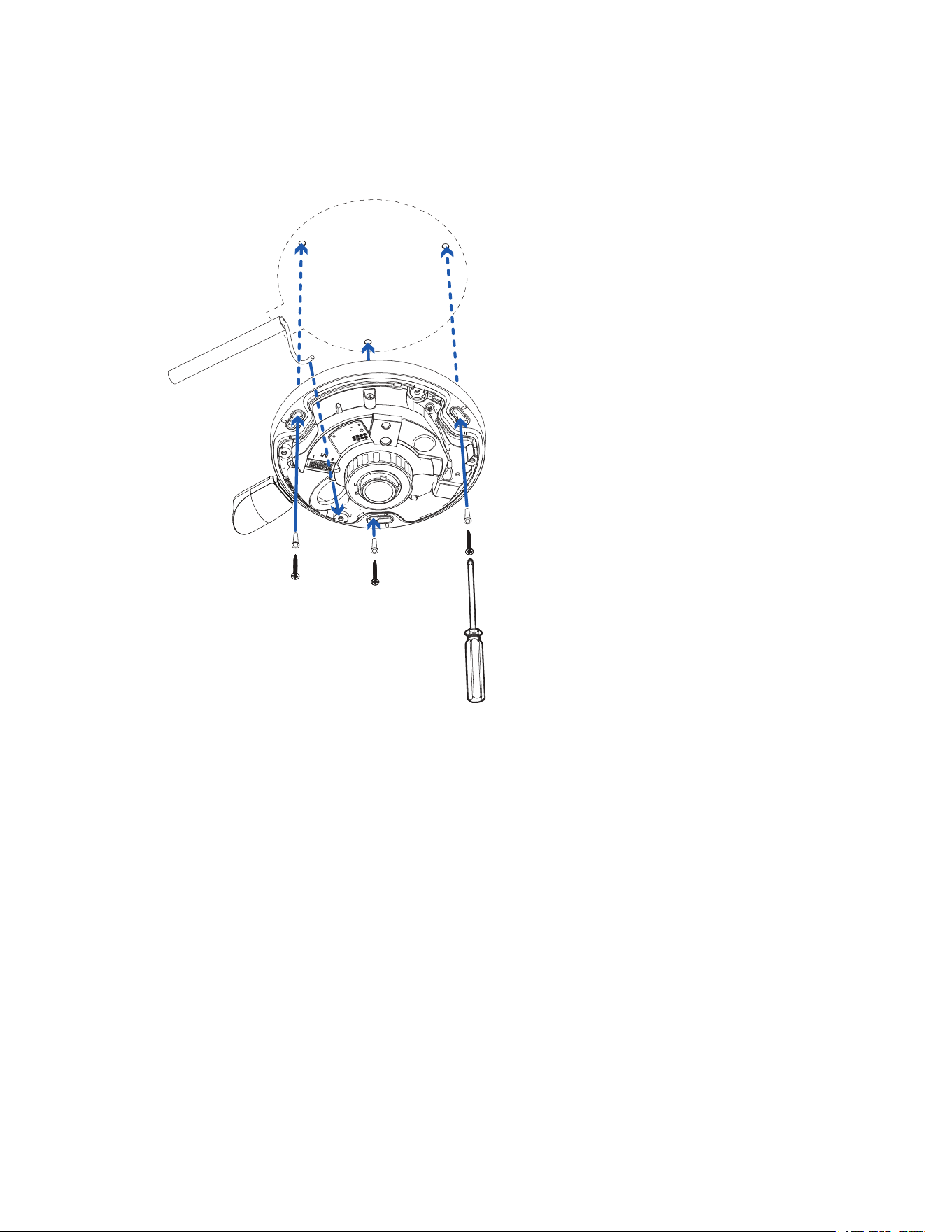
7. Pull the required cables through the cable entry hole on the camera base.
8. Align the up orientation arrow on the camera base with the arrow on the mounting template. Align the
mounting slots on the camera base to the drilled pilot holes and use the provided self-tapping screws
to secure the camera to the mounting surface.
Make sure the cables run through the space provided by the conduit shroud and that they are not
pinched.
9. Pull the required cables through the rubber sealing grommet. For more information, see Preparing
the Cables.
Pelco Fisheye Installation Manual
C6710M | 12/21
26
10. Push the rubber sealing grommet with the required cables into the cable entry hole on the camera
base. The thread around the grommet should line up with the cable entry hole.
The rubber grommet should be pressed firmly into the cable entry hole to create a seal.
Mounting the Camera to an Electrical Box
Perform the following steps if the required electrical components and cables must be contained in an
electrical gang box. To mount the camera to an electrical gang box, you must use the provided wall plate
adapter.
1. Install the electrical gang box as required.
2. Align the wall plate adapter mounting holes to the mounting points on the electrical gang box.
If you are mounting the camera to a wall, make sure the up orientation arrow on the wall plate is at
the top, or the video image will be rotated. For more information, see Mounting in the Correct
Orientation
.
Pelco Fisheye Installation Manual
C6710M | 12/21
27
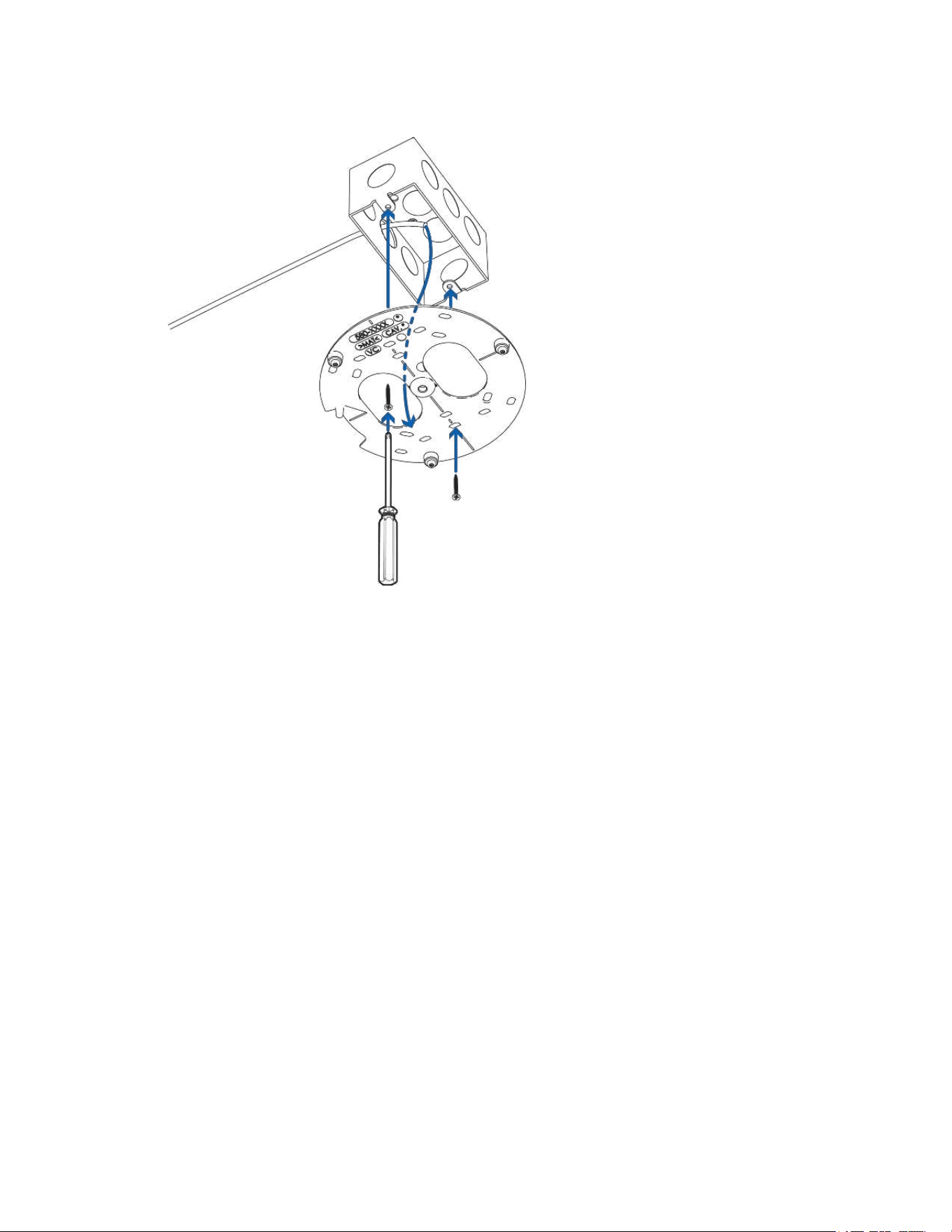
3. Use the provided machine screws to secure the wall plate adapter to the electrical gang box.
4. Pull the required cables through the electrcal box and a cable entry hole on the wall plate. Then feed
the cables through the cable entry hole on the camera base.
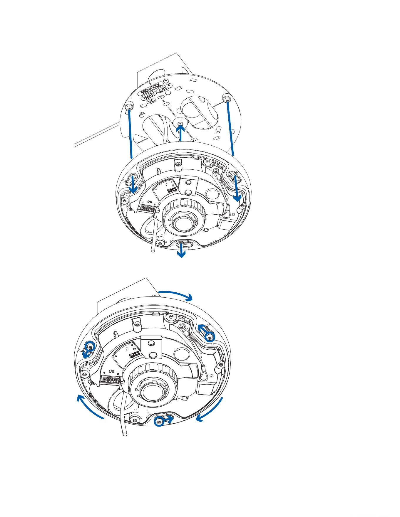
5. Align the up orientation arrow on the camera base with the arrow on the wall plate adapter. Align the
mounting slots on the camera base to the mounting posts on the wall plate adapter and push the
camera base onto the adapter.
Pelco Fisheye Installation Manual
C6710M | 12/21
28
6. Twist the camera base clockwise until the posts come to the right end of the mounting slots.
Pelco Fisheye Installation Manual
C6710M | 12/21
29
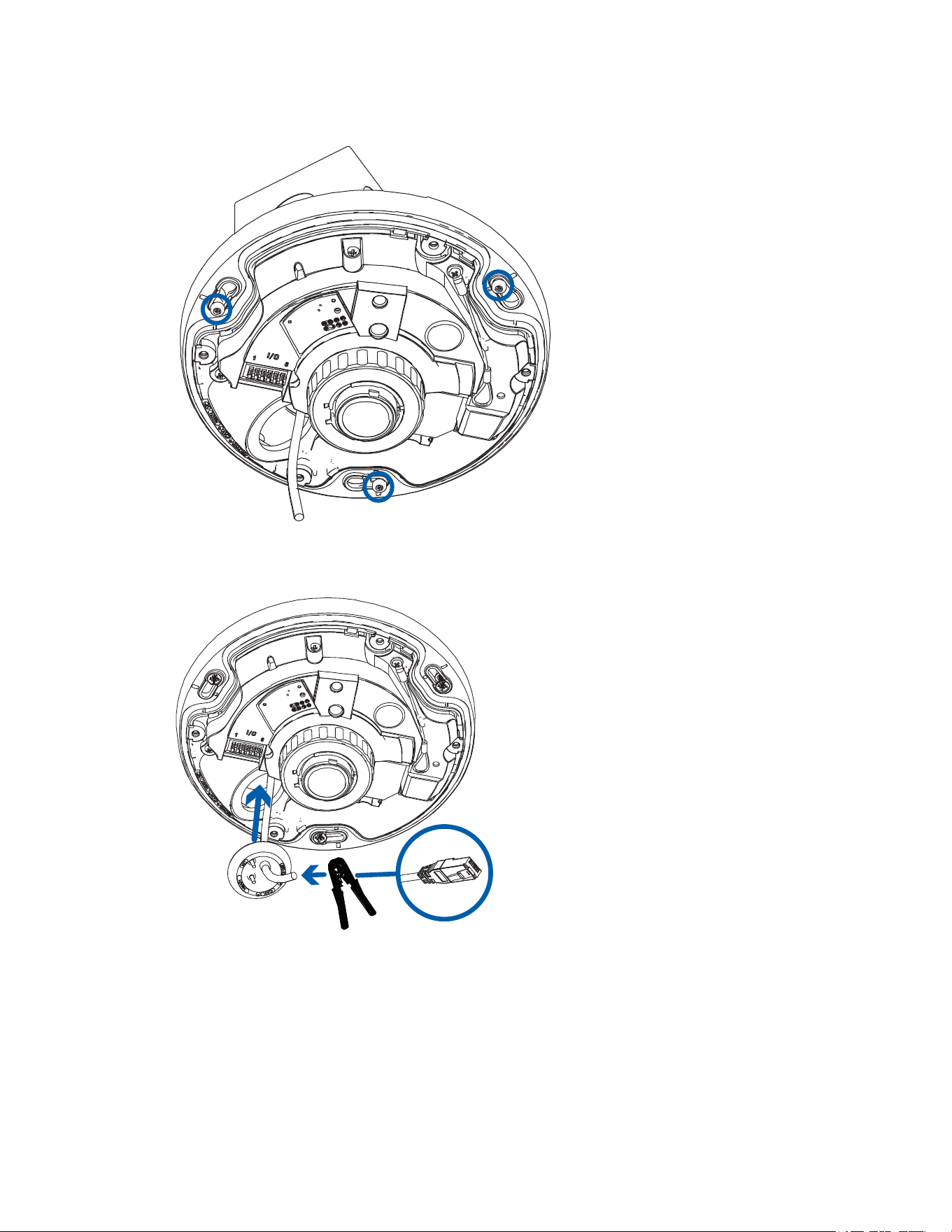
7. Tighten the mounting posts to fix the camera base into place.
8. Pull the required cables through the rubber sealing grommet. For more information, see Preparing
the Cables.
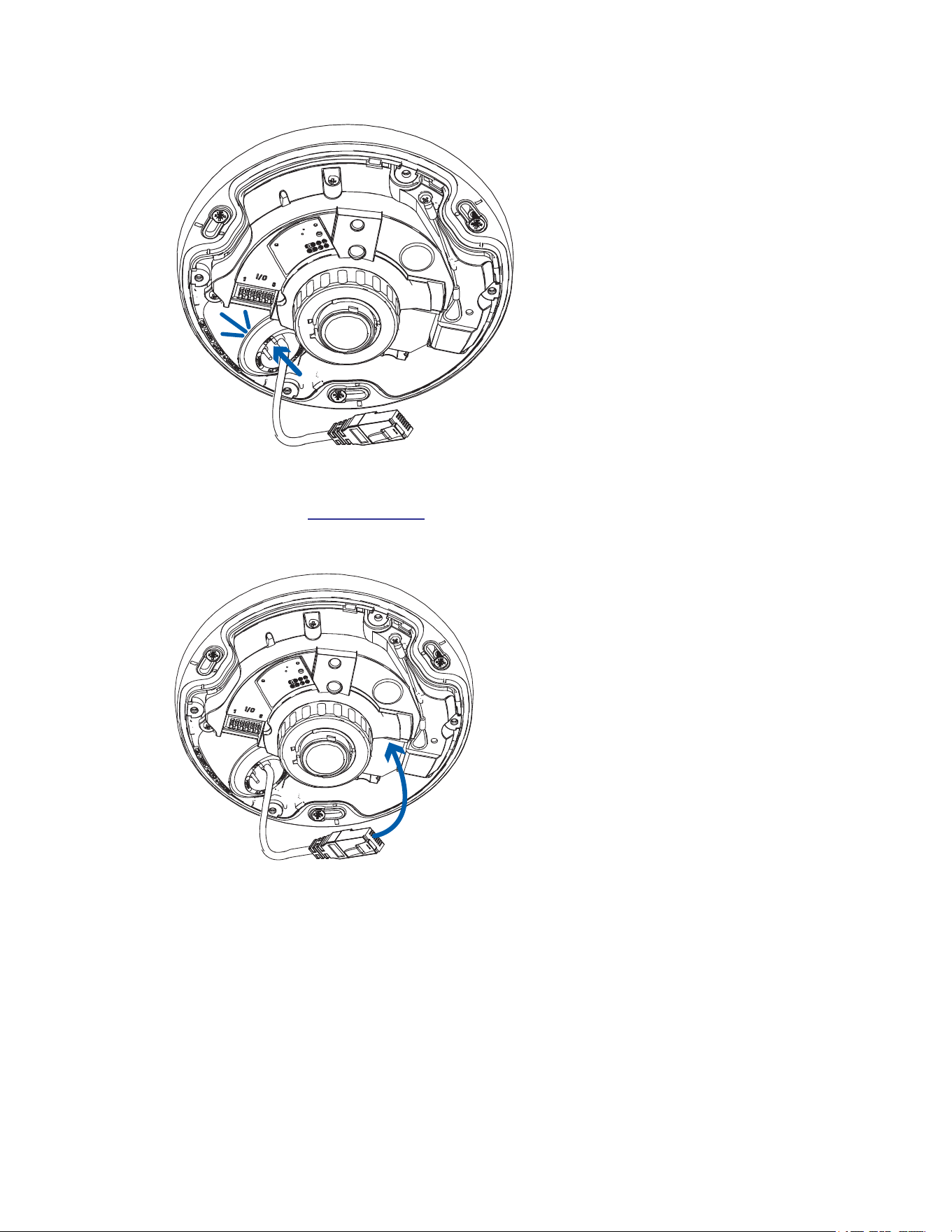
9. Push the rubber sealing grommet with the required cables into the cable entry hole on the camera
base. The thread around the grommet should line up with the cable entry hole.
The rubber grommet should be pressed firmly into the cable entry hole to create a seal.
Pelco Fisheye Installation Manual
C6710M | 12/21
30
Connecting Cables
Refer to the diagrams in the Overview section for the location of the different connectors and status LEDs
on the camera base.
1. Connect a network cable to the camera's Ethernet port (RJ45 connector).
2. If the camera is connected to any external devices, connect the I/O or audio cables to the I/O
connector block. For more information, see Connecting to External Audio and I/O Devices.
3. Power the camera using one of the following methods:
l Power over Ethernet (PoE) Class 3 — If PoE is available, the LEDs will turn on.
l For cameras with IR LEDs, PoE+, IEEE 802.3at Class 4 power is required for maximum
LED power.
l PoE, IEEE 802.3af Class 3 is sufficient to power camera models without IRLEDs. IR-
model cameras will have reduced LED power with IEEE 802.3af Class 3 PoE.
Pelco Fisheye Installation Manual
C6710M | 12/21
31
l External Power — Connect an external 12 V DC power source to the power connector block.
For more information, see
Connecting External Power.
The status LEDs turn on when the camera receives power.
Installing the Fisheye Cover
Be careful not to touch or scratch the dome bubble. Any marks or fingerprints on the dome bubble may
cause unwanted reflections from the IR illuminators.
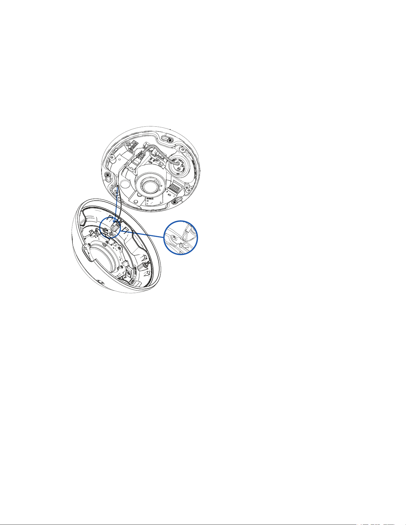
1. Attach the lanyard to the cover.
Pelco Fisheye Installation Manual
C6710M | 12/21
32
2. Attach the cover to the base and tighten the screws with the star-shaped screwdriver.
x4
3. Remove the plastic cover on the dome bubble.
In-Ceiling Mount Installation
Required Tools and Materials
The following tools are required to complete the installation but are not included in the package:
l Appropriate tool for cutting the entry hole in the mounting surface
l Small slotted screwdriver with 5/64” or 2 mm blade width — for connecting power when not using
Power over Ethernet
Camera Package Contents
Ensure the in-ceiling mounted camera package contains the following:
l Pelco IMF Fisheye In-Ceiling Camera
l In-ceiling mounting adapter
l In-ceiling camera cover
l Star-shaped screwdriver
l Power terminal block
l 3-hole rubber grommet — for multi-cable installations.
l Single-hole rubber grommet — for installations with a single Ethernet/PoE cable.
l RJ45 grommet piercing cap — for use with single-hole rubber grommet only
Installation Steps
Complete the following sections to install the device.
Pelco Fisheye Installation Manual
C6710M | 12/21
33
Mounting in the Correct Orientation
The IMF Fisheye camera provides 360° views of large areas. Because of the 360° view, it is not obvious
which part of the camera should be facing up when installed on a wall. To help with this, the mounting
template and the camera body have an up orientation arrow printed on them to signal which end should be
facing up.
When installing the camera on a ceiling, the orientation arrow can go in any direction.
Before removing the mounting template after cutting or drilling the required holes, mark or otherwise make
note of the direction the orientation arrow is facing. This will help you to align the camera body in the same
orientation when installing.
When installing the camera to a wall, make sure that the orientation arrow is facing up, as shown in the
diagram below.
Pelco Fisheye Installation Manual
C6710M | 12/21
34
Using the In-Ceiling Mounting Adapter
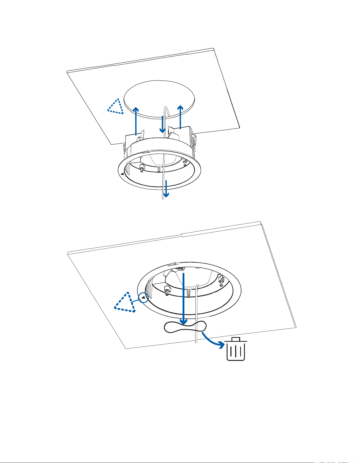
If the camera needs to be installed into a ceiling, install the in-ceiling mounting adapter into the ceiling first.
The maximum supported ceiling thickness is 32 mm (1.25").
1. Use the in-ceiling mounting template to cut an entry hole for the camera into the ceiling. Mark or
otherwise make note of the position of the orientation arrow so that the other parts can be mounted
in the same orientation.
If you are mounting the camera to a wall, make sure the up orientation arrow is at the top, or the
video image will be rotated. For more information, see Mounting in the Correct Orientation.
2. Insert the in-ceiling mounting adapter into the entry hole then pull the required cables through the
adapter. Ensure the orientation arrow on the adapter is facing the same direction as it did on the
mounting template.
Pelco Fisheye Installation Manual
C6710M | 12/21
35
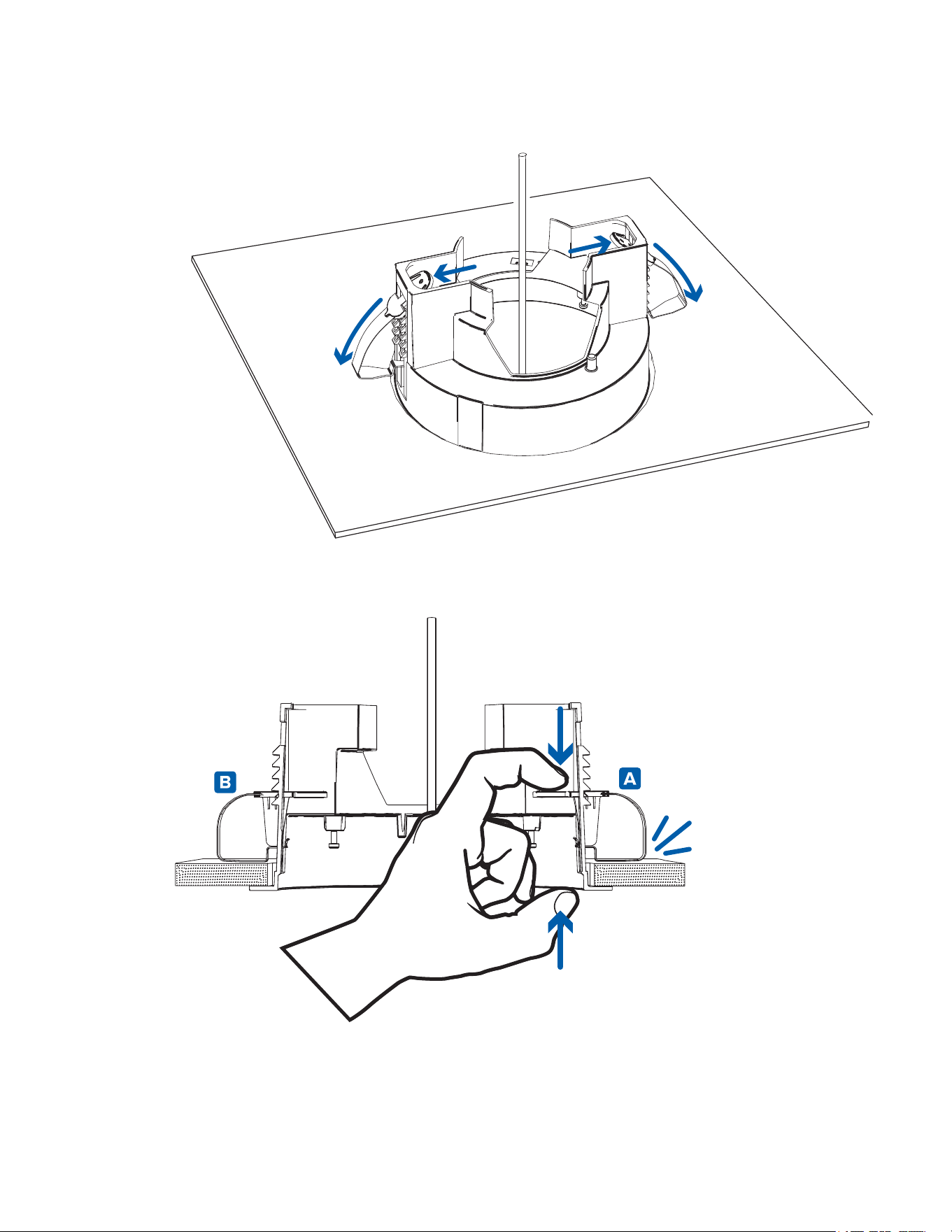
3. Pull off the elastic clamp retainer holding the clamps in place.
Pelco Fisheye Installation Manual
C6710M | 12/21
36
4. Push the orange clamp handles up so that the metal arms extend outside the mounting adapter.
5. With your thumb on the outside edge of the mounting adapter and your forefinger on one of the
orange clamp handles, pinch the clamp down until the clamp is secured.
Pelco Fisheye Installation Manual
C6710M | 12/21
37
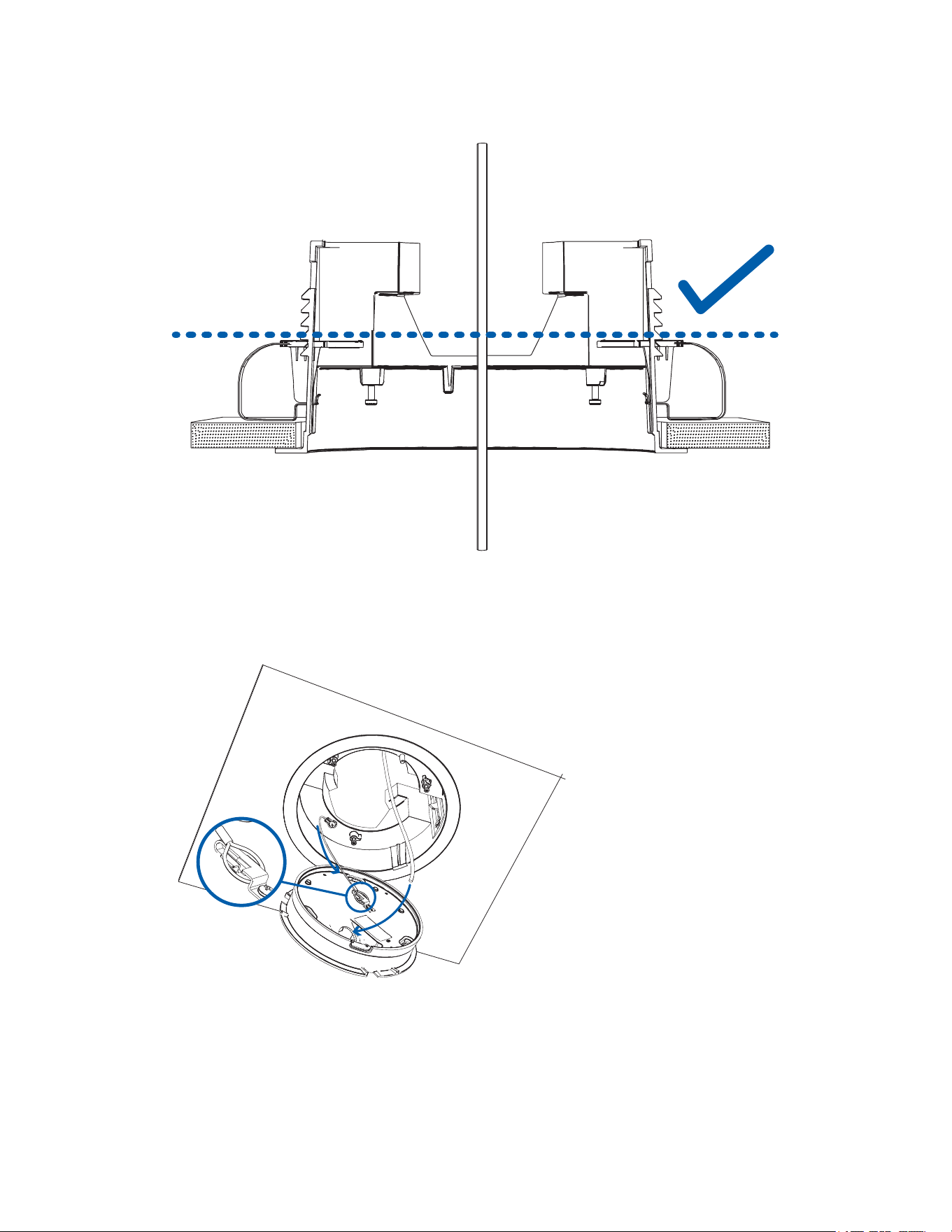
6. Repeat the previous step on the other side. Make sure both clamps are level and horizontal.
Installing the Camera Base into the Mounting Adapter
After you install the mounting adapter, mount the camera base to the adapter.
1. Attach the lanyard on the mounting adapter to the anchor on the camera base.
2. Pull the required cables through the cable entry hole on the camera base.
3. Align the up orientation arrow on the camera base with the arrow on the in-ceiling adapter. Align the
mounting slots on the camera base to the mounting posts on the in-ceiling adapter and push the
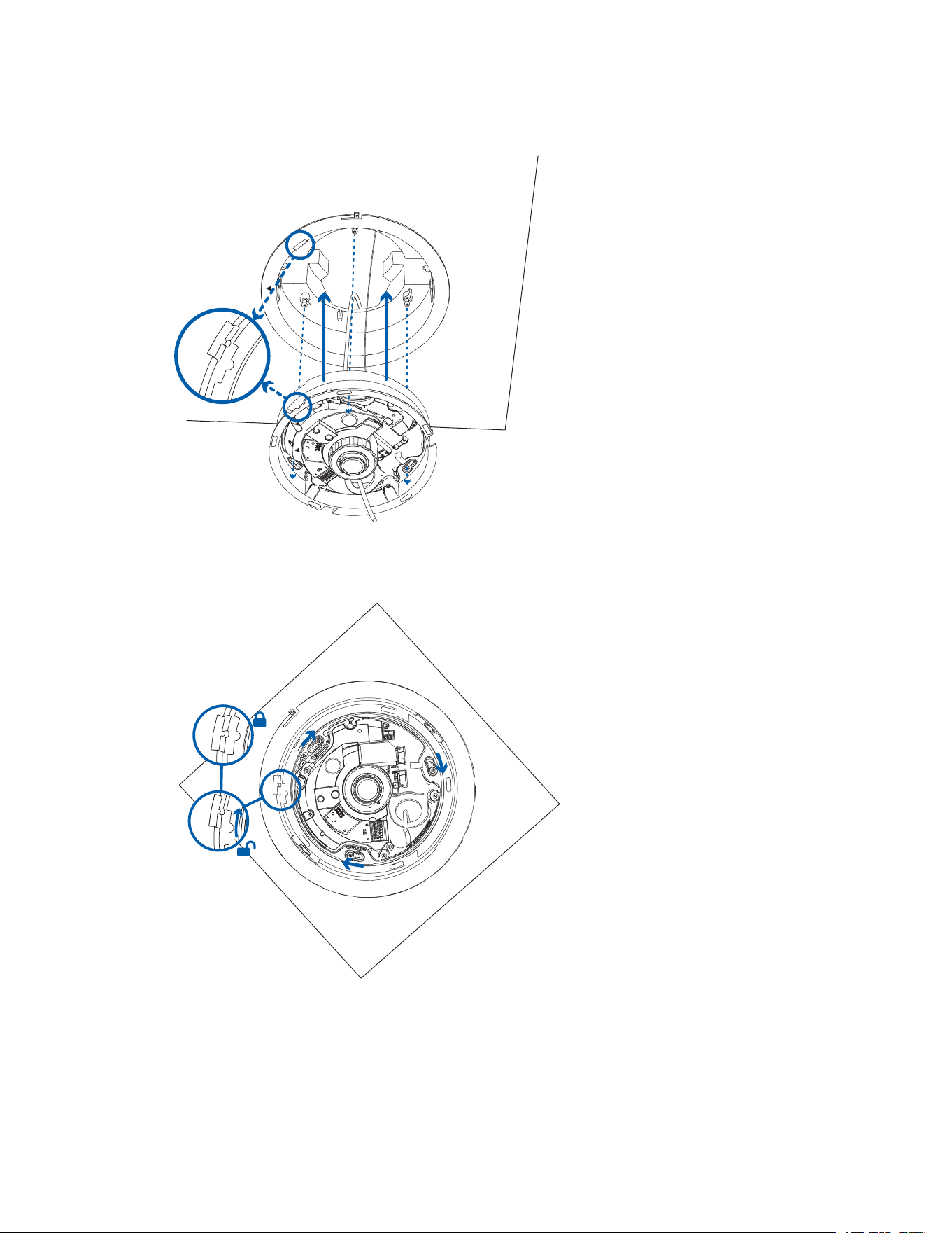
Pelco Fisheye Installation Manual
C6710M | 12/21
38
camera base onto the adapter.
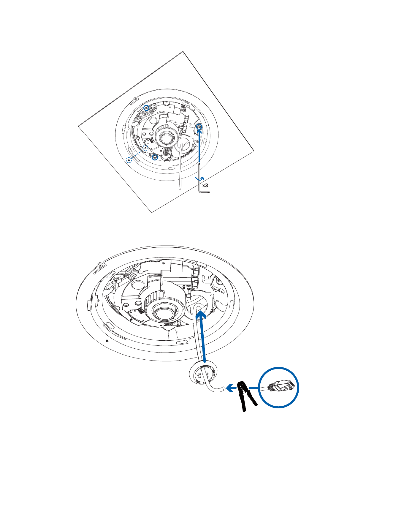
4. Twist the camera base clockwise until the posts come to the right end of the mounting slots and the
alignment feature is in the locked position.
5. Tighten the mounting posts to fix the camera base into place. Ensure that the orientation arrows on
the in-ceiling adapter and camera base point in the same direction.
Pelco Fisheye Installation Manual
C6710M | 12/21
39
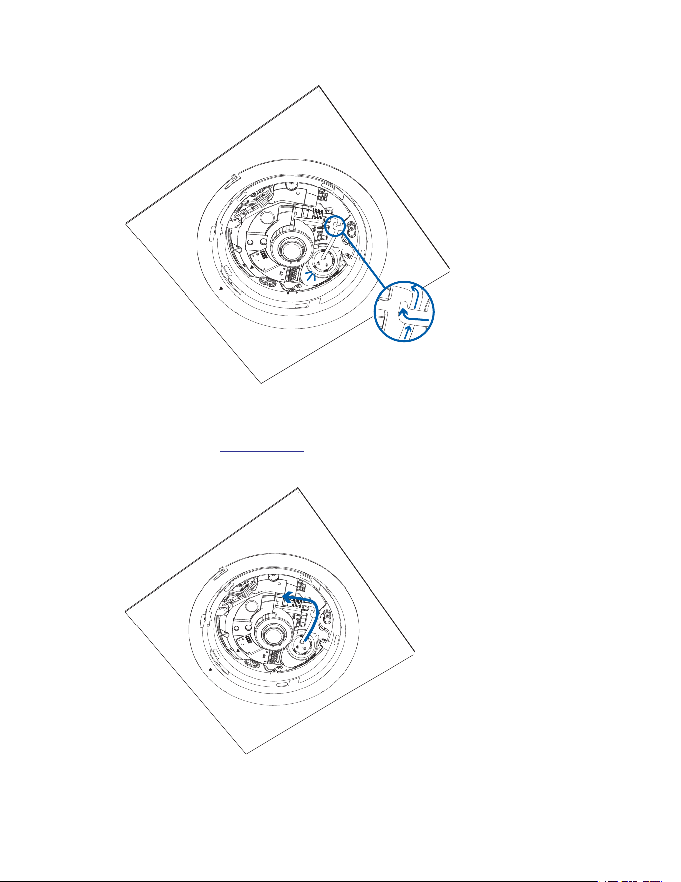
6. Pull the required cables through the rubber sealing grommet. For more information, see Preparing
the Cables.
7. Install the grommet into the cable entry hole on the camera base. Make sure the grommet flange is
securely seated on the inside and outside of the cable entry hole.
Pelco Fisheye Installation Manual
C6710M | 12/21
40
8. Use the cable clip to hold the Ethernet cable in the correct position.
Connecting Cables
Refer to the diagrams in the Overview section for the location of the different connectors and status LEDs
on the camera base.
1. Connect a network cable to the camera's Ethernet port (RJ45 connector).
Pelco Fisheye Installation Manual
C6710M | 12/21
41
2. If the camera is connected to any external devices, connect the I/O or audio cables to the I/O
connector block. For more information, see
Connecting to External Audio and I/O Devices.
3. Power the camera using one of the following methods:
l Power over Ethernet (PoE) IEEE 802.3af Class 3 — If PoE is available, the LEDs will turn on.
l External Power — Connect an external 12 V DC power source to the power connector block.
For more information, see Connecting External Power.
The status LEDs turn on when the camera receives power.
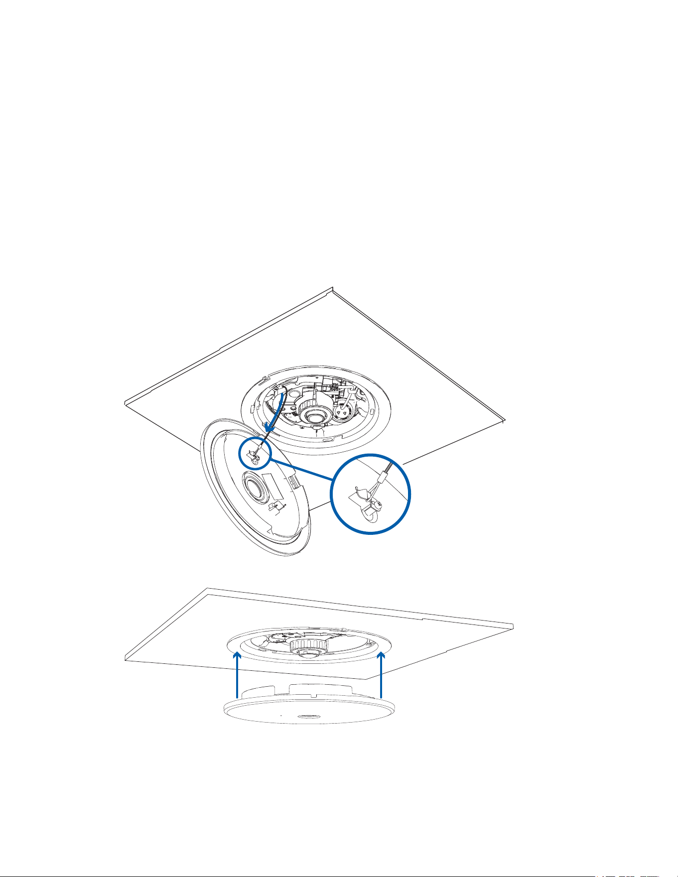
Installing the In-Ceiling Cover
Be careful not to touch or scratch the camera lens. Any marks or fingerprints on the lens may cause
unwanted blurriness.
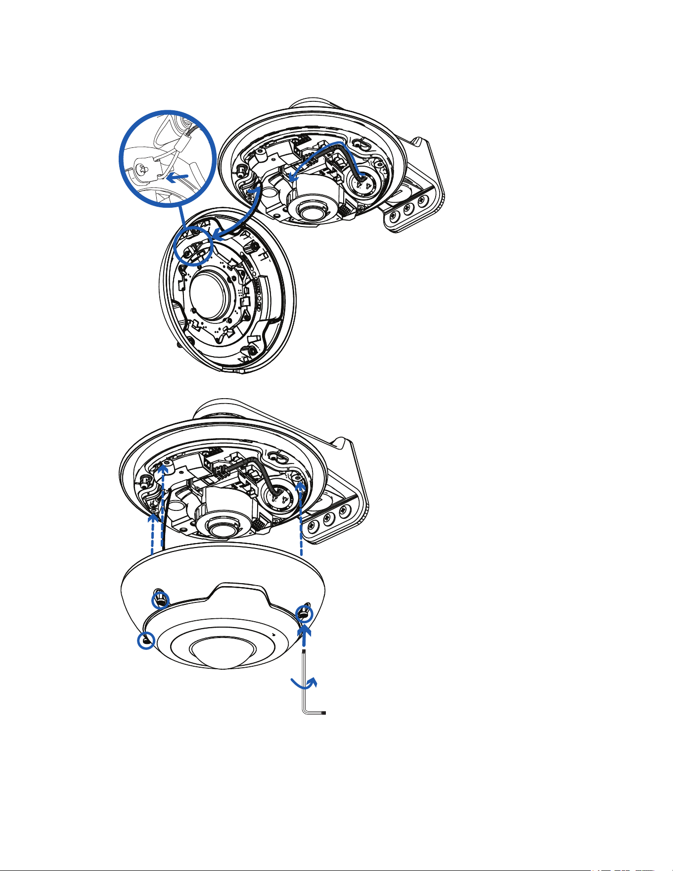
1. Attach the lanyard to the in-ceiling cover.
2. Push the in-ceiling cover onto the camera base.
Pelco Fisheye Installation Manual
C6710M | 12/21
42
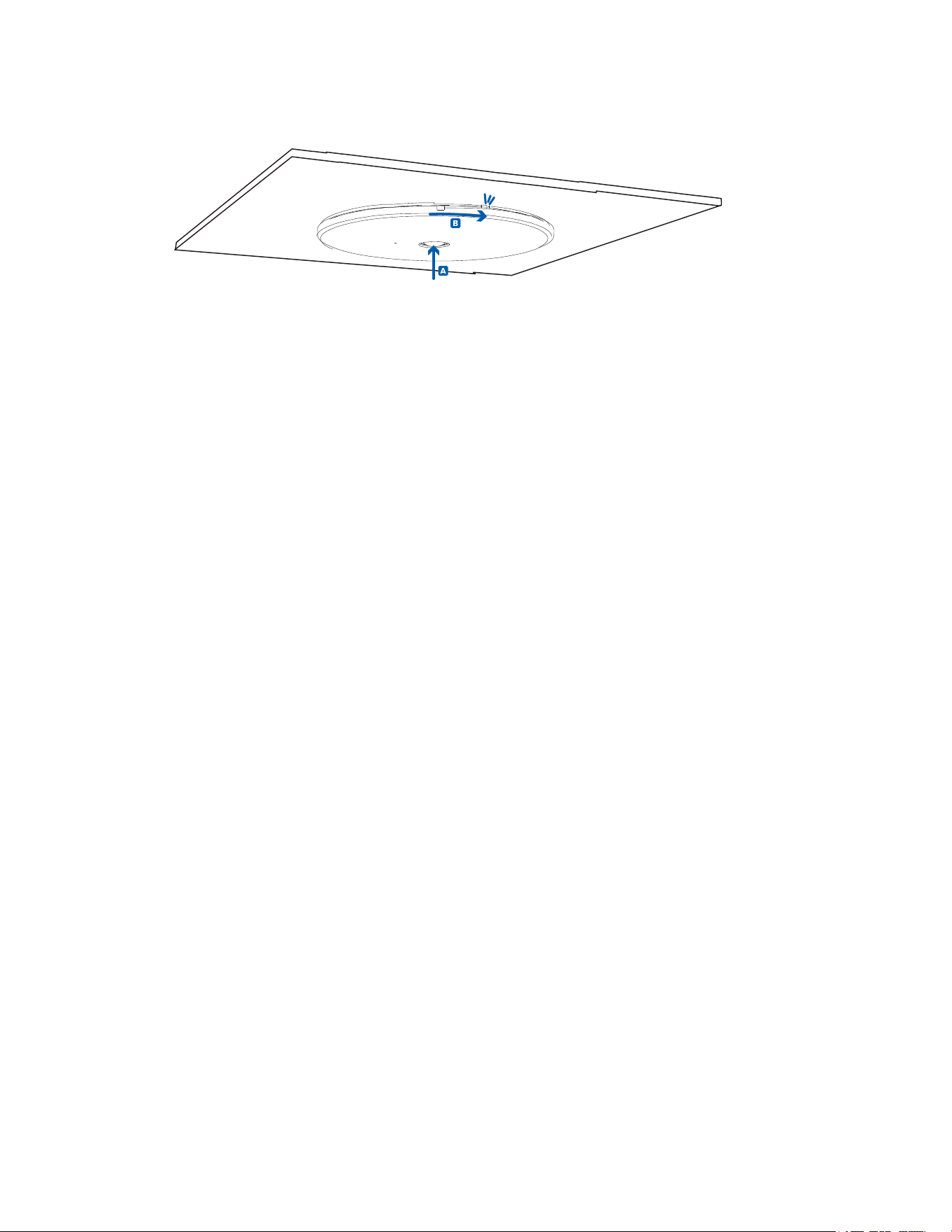
3. Rotate the cover clockwise while pushing up so that it clicks into place.
Pendant Mount Installation
Required Tools and Materials
The following tools are required to complete the installation but are not included in the package:
l Appropriate tool for cutting the cable access hole, if required
l Small slotted screwdriver with 5/64” or 2 mm blade width — for connecting power when not using
Power over Ethernet
Camera Package Contents
Ensure the surface mounted camera package contains the following:
l Pelco IMF Fisheye Camera
l Camera Base Mounting Template sticker
l Optional wall plate adapter — for electrical box installations.
l Star-shaped screwdriver
l Power terminal block
l Optional conduit shroud — for side-entry conduit cabling.
l 3x screws and anchors — for securing the camera to the mounting surface.
l 3-hole rubber grommet — for multi-cable installations.
l Single-hole rubber grommet — for installations with a single Ethernet/PoE cable.
l RJ45 grommet piercing cap — for use with single-hole rubber grommet only
If you are using the optional NPT adapter (IMF-PM), ensure the package contains the following:
l NPT adapter for the IMF Fisheye Camera
Installation Steps
Complete the following sections to install the device.
Mounting the Camera to the WMVE Wall Mount
If the camera will be using the WMVE wall mount, you will need to install the NPT adapter as well.
For information about installing the WMVE wall mount, please refer to the Pelco WMVE Series Installation
Manual.
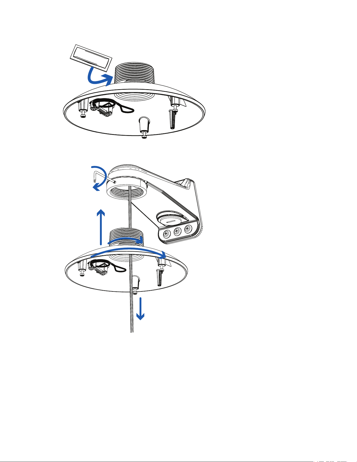
1. Route the wiring through the pendant mount (IMF-PM).
2. To install the NPT adapter, apply anti-seize lubricant (supplied with the WMVE mount) to the
threads of the pendant mount.
Pelco Fisheye Installation Manual
C6710M | 12/21
43
3. Use a 5/64-inch hex Allen wrench (not supplied) to loosen the setscrew, located on the front of the
wall mount, enough to prevent obstruction to the threads of the pendant mount. Screw the pendant
mount adapter onto the mount arm
.
4. Tighten the setscrew located on the front of the wall mount to 16-18 inch-pounds (1.8-20. Nm).
Installing the Camera into the NPT Adapter
Before installing the camera, you must first prepare either the WMVE wall mount or a NPT pipe mount.
The following steps show installation of the camera into the IMF-PM NPT adapter installed onto the WMVE
wall mount. The steps are the same for installing the camera into the IMF-PM NPT adapter installed onto a
pipe.
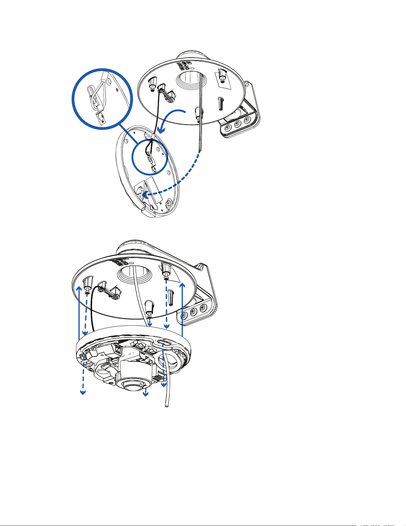
1. Attach the lanyard to the camera base. Pull the required cables through the cable entry hole.
Pelco Fisheye Installation Manual
C6710M | 12/21
44
2. Align the mounting slots on the camera base to the mounting posts on the NPT adapter and push the
camera base onto the adapter.
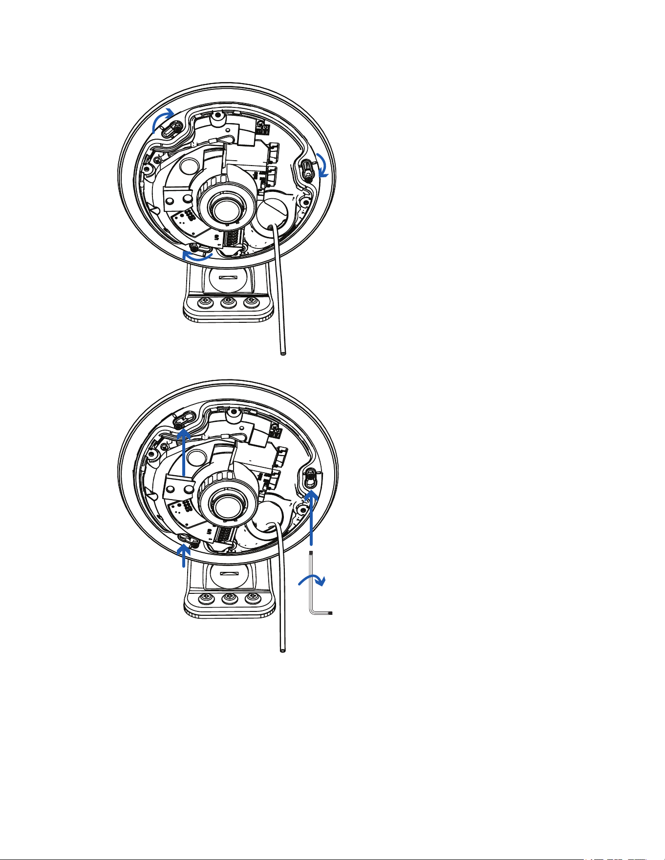
3. Twist the camera base clockwise until the posts come to the right end of the mounting slots.
Pelco Fisheye Installation Manual
C6710M | 12/21
46
6. Push the rubber sealing grommet with the required cables into the cable entry hole on the camera
base. The thread around the grommet should line up with the cable entry hole.
The rubber grommet should be pressed firmly into the cable entry hole to create a seal.
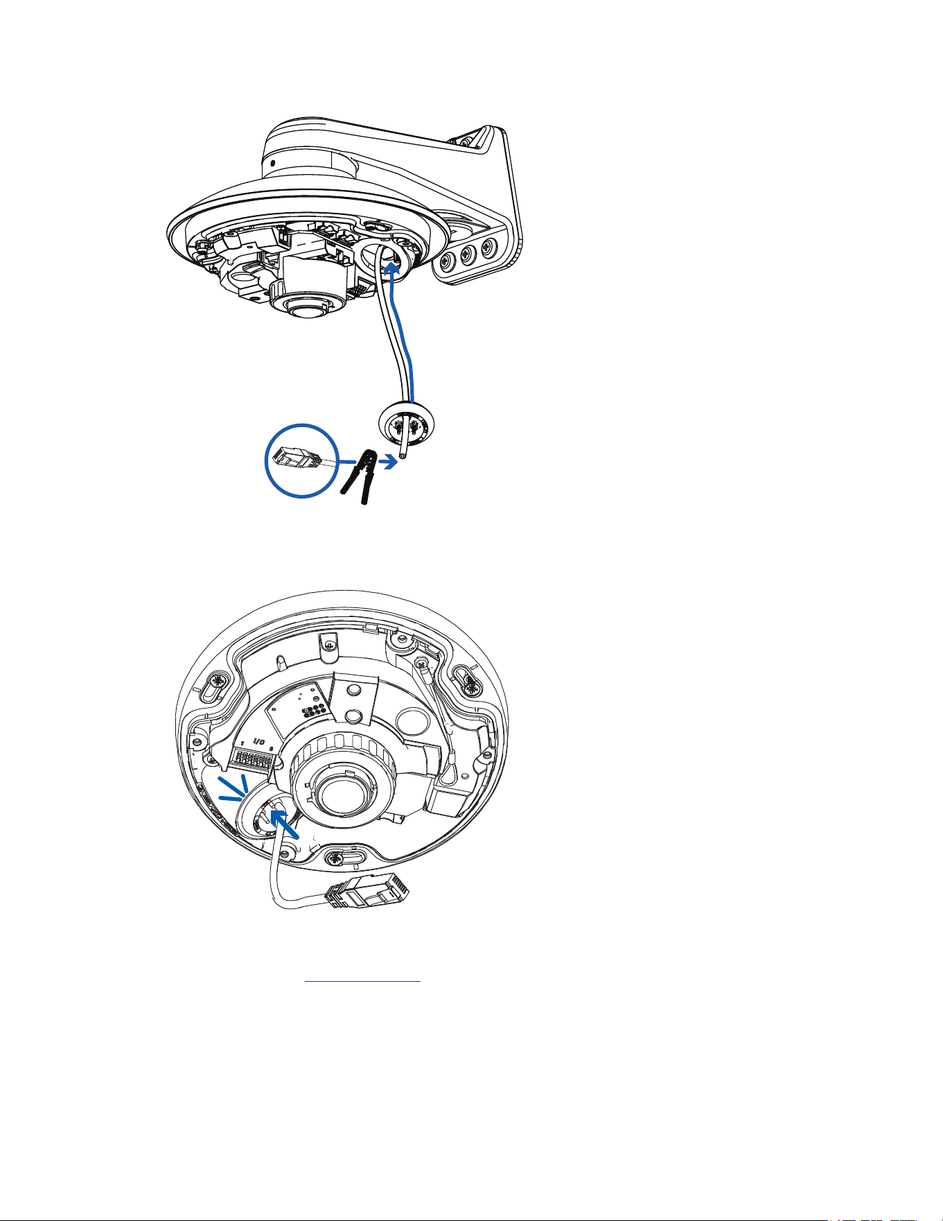
Connecting Cables
Refer to the diagrams in the Overview section for the location of the different connectors and status LEDs
on the camera base.
Pelco Fisheye Installation Manual
C6710M | 12/21
47
1. Connect a network cable to the camera's Ethernet port (RJ45 connector).
2. If the camera is connected to any external devices, connect the I/O or audio cables to the I/O
connector block. For more information, see Connecting to External Audio and I/O Devices.
3. Power the camera using one of the following methods:
l Power over Ethernet (PoE) Class 3 — If PoE is available, the LEDs will turn on.
l For cameras with IR LEDs, PoE+, IEEE 802.3at Class 4 power is required for maximum
LED power.
l PoE, IEEE 802.3af Class 3 is sufficient to power camera models without IRLEDs. IR-
model cameras will have reduced LED power with IEEE 802.3af Class 3 PoE.
l External Power — Connect an external 12 V DC power source to the power connector block.
For more information, see Connecting External Power.
The status LEDs turn on when the camera receives power.
Installing the Fisheye Cover
Be careful not to touch or scratch the dome bubble. Any marks or fingerprints on the dome bubble may
cause unwanted reflections from the IR illuminators.
Pelco Fisheye Installation Manual
C6710M | 12/21
48
1. Attach the lanyard to the cover.
2. Attach the cover to the base and tighten the screws with the star-shaped screwdriver.
x4
3. Remove the plastic cover on the dome bubble.

Pelco Fisheye Installation Manual
C6710M | 12/21
49
Connecting to the Camera
Initializing a Camera Username and Password
You must create a user with administrator privileges before the camera is operational.
If the camera is in the factory default state, you will be redirected to the New User page to create an
administrator user:
1. Enter a new User Name or keep the default administrator name.
2. Enter a new Password for the user. It is recommended to use a secure and complex password.
3. Confirm the new password.
4. For the first user, Administrator must be selected in the Security Group drop-down menu.
5. Click Apply. After creating the user, you will be asked to login.
If you are connecting your Pelco camera to a 3rd party VMS, you will need to set up the first user through
the camera's Web Interface or Camera Configuration Tool before you connect to the 3rd party VMS.
Assigning an IP Address
The device automatically obtains an IP address when it is connected to a network.
If the device cannot obtain an IP address from a DHCP server, it will use Zero Configuration Networking
(Zeroconf) to choose an IP address. When set using Zeroconf, the IP address is in the 169.254.0.0/16
subnet.
The IP address settings can be changed using one of the following methods:
l Device's web browser interface: http://<camera IP address>/.
l Network Video Management software application.
l ARP/Ping method. For more information, see Setting the IP Address Using the ARP/Ping Method.
Accessing the Live VideoStream
Live video stream can be viewed using one of the following methods:
l Web browser interface: http://< camera IP address>/.
l Network Video Management software application.
(Optional) Configuring Onboard Storage
To use the camera’s onboard storage feature, you must insert 1 microSD card into a microSD card slot.
While there are two microSD slots, currently the camera only supports a single microSD card in either slot
for onboard storage. For the location of the microSD card slots, see Overview.
It is recommended that the microSD card have a capacity of 64 GB or more. Video Speed Class microSD
card required, with Class V10 or better recommended. If the microSD card does not meet the
recommended capacity or write speed, the performance of the onboard storage may suffer and result in the
loss of frames or footage.
Ensure the microSD card is designed for continuous video recording or the microSD card life expectancy
may be adversely affected.
Pelco Fisheye Installation Manual
C6710M | 12/21
50
1. Insert the microSD card into the camera.
Do not force the microSD card into the camera or you may damage the card and the
camera. The card can only be inserted in one direction.
2. Access the camera’s web interface to enable the onboard storage feature. For more information, see
the Pelco IMF Fisheye Operations Manual.
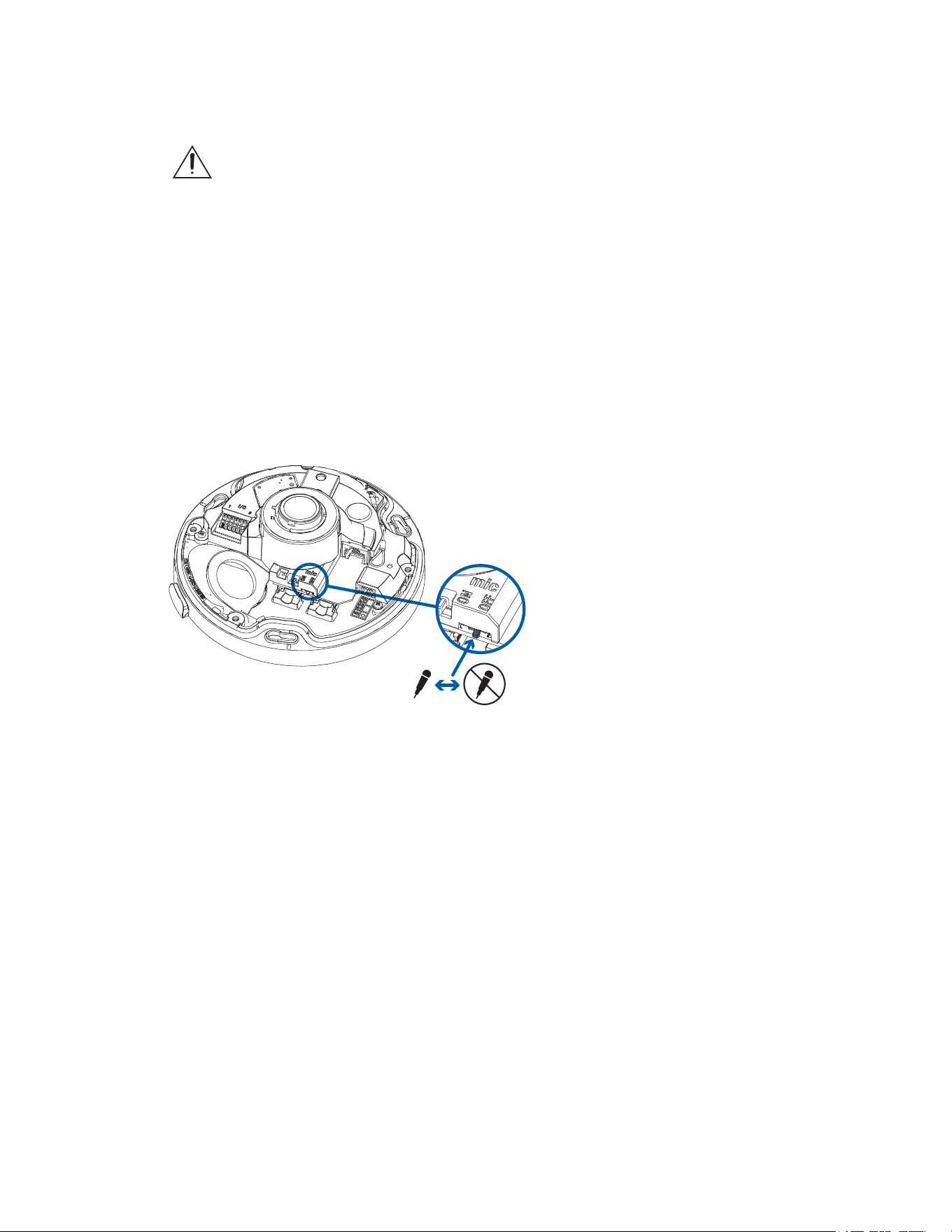
(Optional) Enabling the Microphone
This camera features an internal microphone, and include a switch to physically enable or disable the
microphone. The microphone switch is set to OFF by default.
It is recommended that you enable the microphone before installing the camera in its final location.
1. Locate the microphone switch on the camera assembly.
2. Slide the switch from the default OFFposition to ON to enable the microphone.
Configuring the Microphone
The IMF Fisheye Camera features two microphones: a built-in microphone and an external audio input.
After you've connected the required microphones, you can configure the microphones or line level audio
input from the camera web interface.
l In the camera web interface, the microphones are configured from the Microphone page. You can
adjust the microphone volume by changing the gain.
o
Internal Microphone Gain — configures the gain for the microphone that is built into the
camera.
o
External Source Gain — configures the gain for any line level audio input that is connected to
the audio input connector on the I/O terminal block.
For more information, see the IMF Fisheye Operations Manual.
Pelco Fisheye Installation Manual
C6710M | 12/21
51
Configuring the Camera
After the camera is installed, configure it using the instructions in the current version of the IMF Fisheye
Camera Operations Manual.
For More Information
Additional information about setting up and using the device is available in the following guide:
l Pelco IMF Fisheye Operations Manual available on the Pelco website: www.pelco.com.
Cable Connections
Connecting External Power
If PoE is not available, the camera needs to be powered through the removable power connector block.
Refer to the Overview section for the location of the power connector block.
To connect power to the power connector block, complete the following steps:
1. Remove the power connector block from the camera.
2. Remove the insulation from ¼” (6mm) of the power wires. Do not nick or damage the wires.
3. Insert the two power wires into the two terminals on the power connector block. The connection can
be made with either polarity.
Use a small slotted (5/64” or 2mm blade width) screwdriver to loosen and tighten the terminals.
4. Attach the power connector block back into the camera.
This product is intended to be supplied by a UL Listed Power Unit marked “Class 2” or “LPS” or
“Limited Power Source” with output rated 12 VDC, 11 W min. (26 W min. with -IR model) or PoE,
11 W min. (26 W min. with -IR model).
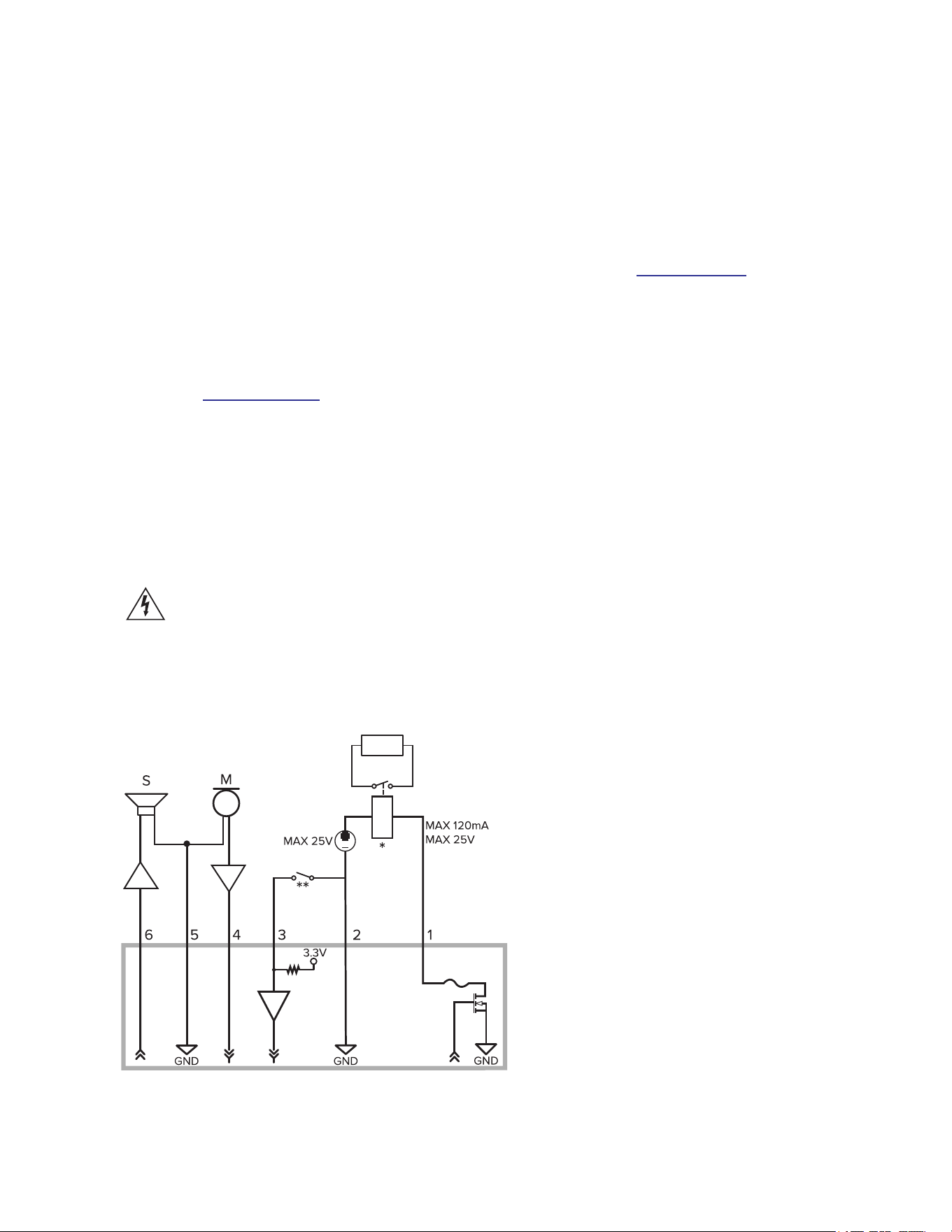
Connecting to External Audio and I/O Devices
External audio and I/O devices are connected to the camera through the audio and I/O connector block.
The pinout for the connector block is shown in the following diagram:

Pelco Fisheye Installation Manual
C6710M | 12/21
52
1. Digital Output — When active, Output is internally connected with the Ground pin. Circuit is open
when inactive. Maximum load is 25 VDC, 120 mA.
2. Ground
3. Digital Input — To activate, connect the Input to the Ground pin. To deactivate, leave disconnected
or apply between 3-15 V.
4. Audio Input (line level)
5. Audio Ground
6. Audio Output (line level)
An external power amplifier should be used when connecting speakers and microphones, as shown
in the diagram.
l * — Relay
l ** — Switch
l M — Microphone
l S — Speaker
Connection Status LED Indicator
Once connected to the network, the green Connection Status LED indicator will display the progress in
connecting to the Network Video Management software.
The following table describes what the LED indicator shows:
Connection State
Connection
Status LED
Indicator Description
Obtaining
IPAddress
One short flash
every second
Attempting to obtain an IP address.
Discoverable Two short flashes
every second
Obtained an IPaddress but not connected to the
NetworkVideo Management software.
Upgrading
Firmware
Two short flashes
and one long flash
every second
Updating the firmware.
Connected On Connected to the Network Video Management software. The
default connected setting can be changed to Off using the
camera's web user interface. For more information see the
Pelco IMF Fisheye Operations Manual.
Troubleshooting Network Connections and LED Behavior
For any of the below LED behaviors, ensure that the camera is getting power and is using a good network
cable before trying another solution.
Pelco Fisheye Installation Manual
C6710M | 12/21
53
LED Behavior Suggested Solution
Green LED is off and amber is on Perform a factory reset of the camera using the physical
firmware revert button. Resetting through the camera's web
interface will not produce the desired result.
Both LEDs are off and the camera is not
connected or streaming video
Check the General setup page in the camera's web interface to
ensure the LEDs are not disabled.
If the LEDs are not disabled, perform a factory reset of the
camera using the physical firmware revert button. Resetting
through the camera's web interface will not produce the desired
result.
Both LEDs are blinking several times at
the same time, then pause and repeat the
blinking
Perform a factory reset of the camera using the physical
firmware revert button. Resetting through the camera's web
interface will not produce the desired result.
A different LED blinking pattern than
those described above
Perform a factory reset of the camera using the physical
firmware revert button. Resetting through the camera's web
interface will not produce the desired result.
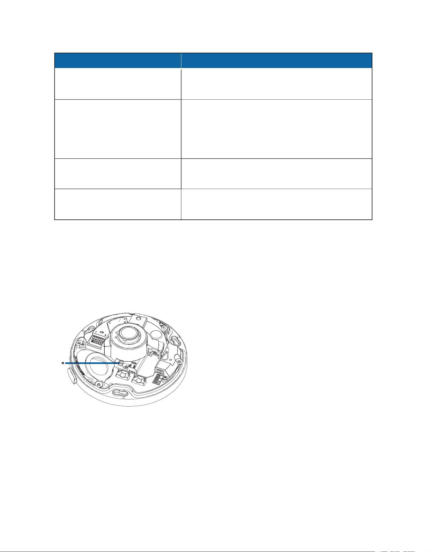
Resetting to Factory Default Settings
If the device no longer functions as expected, you can choose to reset the device to its factory default
settings.
Use the firmware revert button to reset the device. The firmware revert button is shown in the following
diagram:
1. Ensure the camera is powered on.
2. Remove the cover.
3. Press the reset button.
4. The LEDs beside the reset button will turn off.
Wait while the camera reverts to the factory default settings.

Pelco Fisheye Installation Manual
C6710M | 12/21
54
Setting the IP Address Using the ARP/Ping Method
Complete the following steps to configure the camera to use a specific IP address:
The ARP/Ping Method will not work if the Disable setting static IP address through ARP/Ping method
checkbox is selected in the camera's web browser interface. For more information, see the Pelco IMF
Fisheye Operations Manual.
1. Locate and make note of the MAC Address (MAC) listed on the Serial Number Tag for reference.
2. Open a Command Prompt window and enter the following commands:
a. arp -s <New Camera IP Address> <Camera MAC Address>
For example: arp -s 192.168.1.10 00-18-85-12-45-78
b. ping -l 123 -t <New Camera IP Address>
For example: ping -l 123 -t 192.168.1.10
3. Reboot the camera.
4. Close the Command Prompt window when you see the following message:
Reply from <New Camera IP Address>: ...
Cleaning
Dome Bubble
If the video image becomes blurry or smudged in areas, it may be because the dome bubble requires
cleaning.
Cleaning the dome bubble does not apply to in-ceiling models as they do not have a dome bubble. Use
caution if needing to clean the lens. Obtain a lens cleaning swab and solution and follow the cleaning
instructions provided.
To clean the dome bubble:
l Use hand soap or a non-abrasive detergent to wash off dirt or fingerprints.
l Use a microfiber cloth or non-abrasive fabric to dry the dome bubble.
Failure to use the recommended cleaning materials may result in a damaged or scratched dome bubble. A
damaged dome bubble may negatively impact image quality and cause unwanted IR light reflecting into the
lens.
Body
l Use a dry or lightly dampened cloth to clean the camera body.
l Do not use strong or abrasive detergents.

Pelco Fisheye Installation Manual
Pelco, Inc.
625 W. Alluvial Ave., Fresno, California 93711 United States
(800) 289-9100 Tel
(800) 289-9150 Fax
+1 (559) 292-1981 International Tel
+1 (559) 348-1120 International Fax
www.pelco.com
Pelco, the Pelco logo, and other trademarks associated with Pelco products referred to in this publication are trademarks of Pelco, Inc.
or its affiliates. ONVIF and the ONVIF logo are trademarks of ONVIF Inc. All other product names and services are the property of their
respective companies. Product specifications and availability are subject to change without notice.
© Copyright 2021, Pelco, Inc. All rights reserved.