Loading ...
Loading ...
Loading ...

5
Selecting Speed
Use lower speeds for materials such as plastics and
laminates. Also, use lower speeds for hard metals.
Use higher speeds for materials such as wood and
soft metals (aluminum, copper, brass, etc.).
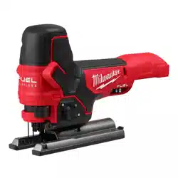
(Cat. No. 2737-20)
To vary the speed, increase or decrease pressure
on the trigger. The further the trigger is pulled, the
greater the speed.
(Cat. No. 2737B-20)
Rotate the speed selector dial to the desired speed
(1 through 6). Select "A" for Auto-Controlled Start to
start out at 1500 SPM and ramps up to 3500 SPM
once the workpiece is contacted.
WARNING
To reduce the risk of injury, wear a
dust mask or use an OSHA compli-
ant dust extraction solution when working in
dusty situations.
Dust Collection Attachment
NOTE: For the 2737B-20, the Dust Collection
Attachment cannot be used with battery packs larger
than 5.0Ah.
1. Remove the battery pack.
2. To install, line-up the small end of the dust collec-
tion attachment with the curved area at the back
of the shoe. Slide into place.
3. To remove, pull the attachment away from saw.
Blower shuttle
Set the blower shuttle to to blow air out the front
of the jig saw to clear the cutting line of dust.
Set the blower shuttle to
to blow air out the dust
chute when using a dust extraction solution.
OPERATION
WARNING
Always remove battery pack before
changing or removing accesso-
ries. Only use accessories specically recom-
mended for this tool. Others may be hazardous.
WARNING
To reduce the risk of injury, always
wear proper eye protection marked
to comply with ANSI Z87.1.
To reduce the risk of injury, be sure the blade
always extends beyond the shoe and workpiece
throughout the stroke. Blades may shatter if they
impact the workpiece.
Starting and Stopping the Tool
(Cat. No. 2737-20)
1. To start the tool, grasp the handle rmly and pull
the trigger.
2. To vary the speed, increase or decrease pressure
on the trigger. The further the trigger is pulled, the
greater the speed.
3. To stop the tool, release the trigger. Allow the tool
to come to a complete stop before removing the
blade from a partial cut or laying the tool down.
(Cat. No. 2737B-20)
1. Set the speed control dial to the desired speed.
2. To start the tool, push the slide switch forward
until tool starts and release.
2. To vary the speed, turn the variable speed dial.
3. To stop the tool, press the slide switch and re-
lease. Allow the tool to come to a complete stop
before removing the blade from a partial cut or
laying the tool down.
NOTE: If the switch is held on for more than 3 sec-
onds, the tool will shut o.
Locking the Trigger
(Cat. No. 2737-20)
To lock the trigger, push the trigger lock from the
lock side of the tool. The trigger will not work while the
switch is in the locked position. Always lock the trigger
and remove the battery pack before performing main-
tenance and changing accessories. Lock the trigger
when storing the tool and when the tool is not in use.
To unlock the trigger, push the trigger lock from the
unlock side of the tool.
Adjusting the Orbital Action
The amount of orbital action may
be adjusted with the orbital ac-
tion selector lever. In general, a
large orbital action (3) should be
used with soft materials and a no
orbital action (0) should be used
with hard materials. When a
smooth cut is required, no orbit
(0) should be used.
Material Orbital Action
Wood 0-3
Metal 0-1
Aluminum 0-1
Plastic 0-2
Smooth Cut 0
WARNING
To reduce the risk of injury, do not
start the tool with the blade con-
tacting the workpiece.
To reduce the risk of injury, be sure the blade
always extends beyond the shoe and workpiece
throughout the stroke. Blades may shatter if they
impact the workpiece.
Loading ...
Loading ...
Loading ...