
6102
Micro-Bath
User’s Guide
January 2013
© 2013 Fluke Corporation. All rights reserved. Specifications are subject to change without notice.
All product names are trademarks of their respective companies.
PN 3729224
1.888.610.7664 sales@GlobalTestSupply.com
Fluke-Direct.com

LIMITED WARRANTY AND LIMITATION OF LIABILITY
Each Fluke product is warranted to be free from defects in material and workmanship under normal use and
service. The warranty period is one year and begins on the date of shipment. Parts, product repairs, and
services are warranted for 90 days. This warranty extends only to the original buyer or end-user customer of
a Fluke authorized reseller, and does not apply to fuses, disposable batteries, or to any product which, in
Fluke's opinion, has been misused, altered, neglected, contaminated, or damaged by accident or abnormal
conditions of operation or handling. Fluke warrants that software will operate substantially in accordance
with its functional specifications for 90 days and that it has been properly recorded on non-defective media.
Fluke does not warrant that software will be error free or operate without interruption.
Fluke authorized resellers shall extend this warranty on new and unused products to end-user customers
only but have no authority to extend a greater or different warranty on behalf of Fluke. Warranty support is
available only if product is purchased through a Fluke authorized sales outlet or Buyer has paid the
applicable international price. Fluke reserves the right to invoice Buyer for importation costs of
repair/replacement parts when product purchased in one country is submitted for repair in another country.
Fluke's warranty obligation is limited, at Fluke's option, to refund of the purchase price, free of charge repair,
or replacement of a defective product which is returned to a Fluke authorized service center within the
warranty period.
To obtain warranty service, contact your nearest Fluke authorized service center to obtain return
authorization information, then send the product to that service center, with a description of the difficulty,
postage and insurance prepaid (FOB Destination). Fluke assumes no risk for damage in transit. Following
warranty repair, the product will be returned to Buyer, transportation prepaid (FOB Destination). If Fluke
determines that failure was caused by neglect, misuse, contamination, alteration, accident, or abnormal
condition of operation or handling, including overvoltage failures caused by use outside the product’s
specified rating, or normal wear and tear of mechanical components, Fluke will provide an estimate of repair
costs and obtain authorization before commencing the work. Following repair, the product will be returned to
the Buyer transportation prepaid and the Buyer will be billed for the repair and return transportation charges
(FOB Shipping Point).
THIS WARRANTY IS BUYER'S SOLE AND EXCLUSIVE REMEDY AND IS IN LIEU OF ALL OTHER
WARRANTIES, EXPRESS OR IMPLIED, INCLUDING BUT NOT LIMITED TO ANY IMPLIED WARRANTY
OF MERCHANTABILITY OR FITNESS FOR A PARTICULAR PURPOSE. FLUKE SHALL NOT BE LIABLE
FOR ANY SPECIAL, INDIRECT, INCIDENTAL, OR CONSEQUENTIAL DAMAGES OR LOSSES,
INCLUDING LOSS OF DATA, ARISING FROM ANY CAUSE OR THEORY.
Since some countries or states do not allow limitation of the term of an implied warranty, or exclusion or
limitation of incidental or consequential damages, the limitations and exclusions of this warranty may not
apply to every buyer. If any provision of this Warranty is held invalid or unenforceable by a court or other
decision-maker of competent jurisdiction, such holding will not affect the validity or enforceability of any other
provision.
11/99
1.888.610.7664 sales@GlobalTestSupply.com
Fluke-Direct.com

iii
Table of Contents
1 Before You Start .......................................................................1
1.1 Symbols Used ........................................................................................... 1
1.2 Safety Information .................................................................................... 2
1.2.1 Warnings .........................................................................................................2
1.2.2 Cautions ..........................................................................................................4
1.3 Authorized Service Centers ..................................................................... 5
2 Introduction .............................................................................7
3 Specications and Environmental Conditions ......................9
3.1 Specifications ........................................................................................... 9
3.2 Environmental Conditions ......................................................................... 9
4 Quick Start .............................................................................. 11
4.1 Unpacking .............................................................................................. 11
4.2 Setup ...................................................................................................... 11
4.3 Power ..................................................................................................... 12
4.4 Setting the Temperature ......................................................................... 12
5 Installation .............................................................................13
5.1 Bath Environment ................................................................................... 13
5.2 “Dry-out” Period ..................................................................................... 13
5.3 Bath Preparation and Filling ................................................................... 13
5.4 Power ..................................................................................................... 14
6 Bath Use .................................................................................15
6.1 General .................................................................................................. 15
6.2 Comparison Calibration ......................................................................... 15
6.3 Calibration of Multiple Probes ................................................................. 16
7 Parts and Controls ................................................................17
7.1 Back and Bottom Panel .......................................................................... 17
7.2 Front Panel .............................................................................................. 18
7.3 Accessories ........................................................................................... 19
7.3.1 Transport/Pour Lid ........................................................................................19
1.888.610.7664 sales@GlobalTestSupply.com
Fluke-Direct.com

iv
7.3.2 Access Cover (Optional) ..............................................................................19
7.3.3 Probe Basket ................................................................................................19
7.3.4 Stir Bar ..........................................................................................................20
7.3.5 Tank Extender (Optional) ..............................................................................20
8 General Operation ..................................................................21
8.1 Switching to 230V Operation .................................................................. 21
8.2 Bath Fluid ............................................................................................... 21
8.2.1 Temperature Range .......................................................................................21
8.2.2 Viscosity ........................................................................................................22
8.2.3 Specific Heat .................................................................................................22
8.2.4 Thermal Conductivity ....................................................................................22
8.2.5 Thermal Expansion........................................................................................22
8.2.6 Electrical Resistivity .......................................................................................22
8.2.7 Fluid Lifetime .................................................................................................23
8.2.8 Safety ............................................................................................................23
8.2.9 Cost ...............................................................................................................23
8.2.10 Commonly Used Fluids .................................................................................23
8.2.10.1 Water (Distilled) ................................................................................................... 24
8.2.10.2 Mineral Oil ............................................................................................................ 24
8.2.10.3 Silicone Oil (Dow Corning 200.10, 200.20) .......................................................... 24
8.2.11 Fluid Characteristics Charts ..........................................................................24
8.2.11.1 Limitations and Disclaimer .................................................................................. 25
8.2.11.2 About the Graph .................................................................................................. 26
8.3 Stirring .................................................................................................... 27
8.4 Power ...................................................................................................... 28
8.5 Heater ..................................................................................................... 28
8.6 Fluid Drain ............................................................................................... 28
8.7 Temperature Controller .......................................................................... 28
9 Controller Operation ..............................................................31
9.1 Well Temperature ................................................................................... 31
9.2 Temperature Set-point ........................................................................... 31
9.2.1 Programmable Set-points ............................................................................31
9.2.2 Set-point Value .............................................................................................33
9.2.3 Temperature Scale Units ..............................................................................33
9.3 Scan ....................................................................................................... 34
9.3.1 Scan Control .................................................................................................34
9.3.2 Scan Rate .....................................................................................................34
9.4 Temperature Display Hold ..................................................................... 35
1.888.610.7664 sales@GlobalTestSupply.com
Fluke-Direct.com

v
9.4.1 Hold Temperature Display ............................................................................35
9.4.2 Mode Setting ................................................................................................35
9.4.3 Switch Wiring ................................................................................................36
9.4.4 Switch Test Example ....................................................................................36
9.5 Secondary Menu .................................................................................... 36
9.6 Heater Power .......................................................................................... 37
9.7 Proportional Band .................................................................................. 37
9.8 Cutout .................................................................................................... 38
9.9 Controller Configuration .......................................................................... 39
9.10 Operating Parameters ............................................................................ 39
9.10.1 Stir Speed ......................................................................................................39
9.10.2 High Limit .....................................................................................................40
9.10.3 Cutout Reset Mode .......................................................................................40
9.11 Serial Interface Parameters ................................................................... 41
9.11.1 BAUD Rate ....................................................................................................41
9.11.2 Sample Period ...............................................................................................41
9.11.3 Duplex Mode .................................................................................................42
9.11.4 Linefeed .......................................................................................................42
9.12 Calibration Parameters ........................................................................... 43
9.12.1 R0 .................................................................................................................43
9.12.2 ALPHA ..........................................................................................................43
9.12.3 DELTA ...........................................................................................................43
9.12.4 C0 and CG ....................................................................................................44
9.12.5 rCAL ..............................................................................................................44
10 Digital Communication Interface ..........................................45
10.1 Serial Communications .......................................................................... 45
10.1.1 Wiring ...........................................................................................................45
10.1.2 Setup ............................................................................................................45
10.1.2.1 Baud Rate ........................................................................................................... 46
10.1.2.2 Sample Period ...................................................................................................... 46
10.1.2.3 Duplex Mode ........................................................................................................ 46
10.1.2.4 Linefeed ................................................................................................................ 46
10.1.3 Serial Operation ............................................................................................46
10.2 Interface Commands .............................................................................. 47
11 Test Probe Calibration ...........................................................49
11.1 Calibrating a Single Probe ..................................................................... 49
11.2 Stabilization and Accuracy .................................................................... 49
1.888.610.7664 sales@GlobalTestSupply.com
Fluke-Direct.com

vi
11.3 Multiple Probe Calibration ..................................................................... 49
12 Calibration Procedure ...........................................................51
12.1 Calibration Points ................................................................................... 51
12.2 Calibration Procedure ............................................................................ 51
12.2.1 Compute DELTA ...........................................................................................52
12.2.2 Compute R0 & ALPHA ..................................................................................52
12.2.3 Accuracy & Repeatability .............................................................................53
13 Maintenance ...........................................................................55
14 Troubleshooting .....................................................................57
14.1 Troubleshooting Problems, Possible Causes, and Solutions ................. 57
14.2 CE Comments ......................................................................................... 58
14.2.1 EMC Directive ...............................................................................................58
14.2.2 Low Voltage Directive (Safety) ......................................................................58
1.888.610.7664 sales@GlobalTestSupply.com
Fluke-Direct.com

vii
Tables
Table 1 International Electrical Symbols ........................................................... 1
Table 2 Specifications ....................................................................................... 9
Table 3 Table of Various Bath Fluids ............................................................... 25
Table 4 Nominal Stirrer Motor Settings With Different Liquids ........................ 28
Table 5 Controller Communications Commands ............................................. 48
1.888.610.7664 sales@GlobalTestSupply.com
Fluke-Direct.com

viii
Figures
Figure 1 6102 Back Panel and Bottom ............................................................ 17
Figure 2 6102 Front Panel ................................................................................ 18
Figure 3 Bath Lids and Lid Parts ..................................................................... 19
Figure 4 Probe Basket ..................................................................................... 20
Figure 5 Stir Bar ............................................................................................... 20
Figure 6 Chart of Various Bath Fluids ............................................................. 26
Figure 7 Controller Operation Flowchart ......................................................... 32
Figure 8 Serial Cable Wiring ........................................................................... 45
1.888.610.7664 sales@GlobalTestSupply.com
Fluke-Direct.com
1
Before You Start
Symbols Used
Before You Start1
Symbols Used1.1
Table 1 lists the International Electrical Symbols. Some or all of these symbols may be
used on the instrument or in this manual.
Table 1 International Electrical Symbols
Symbol Description
AC (Alternating Current)
AC-DC
Battery
CE
DC
Double Insulated
Electric Shock
Fuse
PE Ground
Hot Surface (Burn Hazard)
Read the User’s Guide (Important Information)
Off
On
Canadian Standards Association
1.888.610.7664 sales@GlobalTestSupply.com
Fluke-Direct.com
6102 Micro-Bath User’s Guide
Safety Information
2
Symbol Description
C-TICK Australian EMC mark
The European Waste Electrical and Electronic Equipment (WEEE) Directive (2002/96/
EC) mark.
OVERVOLTAGE (Installation) CATEGORY II, Pollution Degree 2 per IEC1010-1 re fers to
the level of Impulse Withstand Voltage protection provided. Equipment of OVERVOLTAGE
CATEGORY II is energy-consuming equipment to be supplied from the xed installation.
Examples include household, office, and laboratory appliances.
Safety Information 1.2
Use this instrument only as specified in this manual. Otherwise, the protection
provided by the instrument may be impaired.
The following definitions apply to the terms “Warning” and “Caution”.
“Warning” identifies conditions and actions that may pose hazards to the user.
L
“Caution” identifies conditions and actions that may damage the instru ment
L
being used.
Warnings1.2.1
To avoid personal injury, follow these guidelines.
GENERAL
DO NOT use the instrument for any application other than calibration work. The
instrument was designed for temperature calibration. Any other use of the unit may
cause unknown hazards to the user.
DO NOT overfill the bath. Overflowing extremely cold or hot fluid may be harmful to
the operator. See Section 5.3, Bath Preparation and Filling, for specific instructions.
DO NOT install access cover without holes onto a bath that is energized. Dangerous
pressures may result from fluids vaporizing.
Calibration Equipment should only be used by Trained Personnel.
If this equipment is used in a manner not specified by the manufacturer, the protection
provided by the equipment may be impaired.
Before initial use, or after transport, or after storage in humid or semi-humid
environments, or anytime the instrument has not been energized for more than 10
days, the instrument needs to be energized for a “dry-out” period of 2 hours before
it can be assumed to meet all of the safety requirements of the IEC 61010-1. If the
product is wet or has been in a wet environment, take necessary measures to remove
moisture prior to applying power such as storage in a low humidity temperature
chamber operating at 50°C for 4 hours or more.
1.888.610.7664 sales@GlobalTestSupply.com
Fluke-Direct.com

3
Before You Start
Safety Information
Overhead clearance is required. Do not place the instrument under a cabi net or other
structure. Always leave enough clearance to allow for safe and easy insertion and
removal of probes.
The instrument is intended for indoor use only.
DO NOT use the unit in environments other than those listed in the user’s guide.
DO NOT carry the unit without the transport lid in place and properly se cured.
Thoroughly wipe the inside of the well dry when changing fluids as some high
temperature fluids react violently to water or other liquid mediums.
Use of this instrument at HIGH TEMPERATURES for extended periods of time
requires caution.
Completely unattended high temperature operation in not recommended.
BURN HAZARD
High temperatures may be present in this equipment. Fires and severe burns may result
if personnel fail to observe safety precautions.
DO NOT mix water and oil when exceeding temperatures of 90°C (194°F).
ELECTRICAL HAZARD
These guidelines must be followed to ensure that the safety mechanisms in this
instrument will operate properly. This instrument must be plugged into an AC only
electric outlet as listed in Section 3.1, Specifications. The power cord of the instrument
is equipped with a three-pronged grounding plug for your protection against electrical
shock haz ards. It must be plugged directly into a properly grounded three-prong
receptacle. The receptacle must be installed in accordance with local codes and
ordinances. DO NOT use an extension cord or adapter plug.
DO use a ground fault interrupt device. This unit contains a liquid. A ground fault
device is advised in case liquid is present in the electrical system and could cause an
electrical shock.
Always replace the power cord with an approved cord of the correct rating and type. If
you have questions, contact an Authorized Service Center (see Section 1.3).
High voltage is used in the operation of this equipment. Severe injury or death may
result if personnel fail to observe the safety precautions. Before working inside the
equipment, turn off the power and disconnect the power cord.
DO NOT connect this unit to a non-grounded, non-polarized outlet.
Always replace the fuse with one of the same rating, voltage, and type.
1.888.610.7664 sales@GlobalTestSupply.com
Fluke-Direct.com

6102 Micro-Bath User’s Guide
Safety Information
4
BATH FLUIDS
Fluids used in this unit may produce noxious or toxic fumes under certain
circumstances. Consult the fluid manufacturer’s MSDS (Material Safety Data Sheet).
Proper ventilation and safety precautions must be observed.
The unit is equipped with a soft cutout (user settable firmware) and a hard cutout.
Check the flash point, boiling point, or other fluid characteristic applicable to the
circumstances of the unit operation. Ensure that the soft cutout is adjusted to the fluid
characteristics of the application. DO NOT exceed the boiling or flash temperatures of
the fluid being used.
Cautions1.2.2
DO NOT overfill the bath. Overflowing liquid may damage the electrical system. Be
sure to allow for thermal expansion of the fluid as the bath temperature increases. See
Section 5.3, Bath Preparation and Filling, for specific instructions.
Read Section 6, Bath Use, before placing the unit into service.
DO NOT change the values of the bath calibration constants from the fac tory set
values. The correct setting of these parameters is important to the safety and proper
operation of the unit.
The Factory Reset Sequence should be performed only by authorized personnel if
no other action is successful in correcting a malfunction. You must have a copy of the
most recent Report of Test to restore the test pa rameters.
Most probes have handle temperature limits. Be sure that the probe handle temperature
limit is not exceeded in the air above the instrument.
The instrument and any thermometer probes used with it are sensitive in struments that
can be easily damaged. Always handle these devices with care. Do not allow them to
be dropped, struck, stressed, or overheated.
Operate the instrument in room temperatures as listed in Section 3.2, Environmental
Conditions. Allow sufficient air circulation by leaving at least 6 inches of space be-
tween the instrument and nearby objects.
Overhead clearance needs to al low for safe and easy insertion and removal of probes
for calibration.
Use only clean fluid with the instrument.
The Micro-Bath is a precision instrument. Although it has been designed for optimum
durability and trouble free operation, it must be handled with care. Always carry the
unit in an upright position to prevent the liquid from spilling out. The convenient
fold-up handle allows one hand carry ing. The instrument should not be operated in
excessively wet, oily, dusty, or dirty environments. It is important to keep the well of
the instrument clean and clear of any foreign matter. Do not operate near flammable
ma terials.
1.888.610.7664 sales@GlobalTestSupply.com
Fluke-Direct.com

5
Before You Start
Authorized Service Centers
If a mains supply power fluctuation occurs, immediately turn off the in strument.
Power bumps from brown-outs and black-outs could damage the instrument. Wait
until the power has stabilized before re-energizing the instrument.
Components and heater lifetime can be shortened by continuous high temperature
operation.
DO NOT operate the instrument without fluid.
The input voltage and heater voltage switch settings must always be set to the same
value.
1.3 Authorized Service Centers
Please contact one of the following authorized Service Centers to coordinate service
on your Hart product.
1.888.610.7664 sales@GlobalTestSupply.com
Fluke-Direct.com

6102 Micro-Bath User’s Guide
Authorized Service Centers
6
When contacting these Service Centers for support, please have the following
information available:
Model Number
L
Serial Number
L
Voltage
L
Complete description of the problem
L
1.888.610.7664 sales@GlobalTestSupply.com
Fluke-Direct.com

7
Introduction
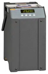
Introduction 2
The Hart Scientific 6102 Micro-Bath may be used as a portable instrument or bench
top temperature calibrator for calibrating thermocouple and RTD temper ature probes.
The 6102 is small enough to use in the field, and accurate enough to use in the lab.
Calibrations may be done over a range of 35°C to 200°C (95°F to 392°F). The
resolution of the 6102 temperature display is 0.01 degrees.
The Micro-Bath calibrator features:
Convenient handle
L
RS-232 interface
L
Switchable AC Input (115 VAC or 230 VAC)
L
Built in programmable features include:
Temperature scan rate control
L
Temperature switch hold
L
Eight Set-point memory
L
Adjustable readout in °C or °F
L
The temperature is accurately controlled by Hart’s digital con troller. The controller
uses a precision platinum RTD as a sensor and controls the well temperature with a
solid state relay (triac) driven heater.
The LED front panel continuously shows the current well temperature. The
temperature may be easily set with the control buttons to any desired tempera ture
within the specified range. The calibrator’s multiple fault protection de vices insure
user and instrument safety and protection.
The 6102 Micro-Bath was designed for portability, low cost, and ease of opera tion.
Through proper use, the instrument will continuously provide accurate calibration
of temperature sensors and devices. The user should be familiar with the safety
guidelines and operating procedures of the calibrator as de scribed in the instruction
manual.
1.888.610.7664 sales@GlobalTestSupply.com
Fluke-Direct.com

1.888.610.7664 sales@GlobalTestSupply.com
Fluke-Direct.com

9
Specications and Environmental Conditions
Specications
Specications and Environmental Conditions3
3.1 Specications
The 6102 may not meet the specification published if a different fluid is used other
than distilled water or Dow Corning (200.10, 200.20) oil.
Do not exceed the boiling point or flash point temperatures of the fluid. To ensure that
the boiling and flash point temperatures are not exceeded adjust the High Limit and
Cutout parameters. To set these parameters, refer to Section 9, Controller Operation.
Specifications Table 2
Range 35 to 200°C (95 to 392°F)
Accuracy ±0.25°C
Stability ±0.02°C at 100°C
±0.03°C at 200°C
Uniformity ±0.02°C
Resolution 0.01°C/F
Operating Temperature 5 to 45°C (41 to 113°F)
Heating Time 25°C to 200°C: 40 minutes
Cooling Time 200°C to 100°C: 35 minutes
Well Size 1.9" dia. x 5.5" deep (48 x 139 mm)
Size 5.5" W x 10.38" H x 8" D (14 x 26 x 20 cm)
Weight 10 lb. (4.5 kg) with uid
Power 115 VAC (±10%), 12.3 A, or 230 VAC (±10%), 1.1 A, switchable, 50/60 Hz,
270 W
System Fuse 115 V: 250 V, 3A, F
230 V: 250 V, 1.6A, F
Safety Overvoltage (Installation) Category II, Pollution Degree 2 per IEC 61010-01
3.2 Environmental Conditions
Although the instrument has been designed for optimum durability and trou ble-free
operation, it must be handled with care. The instrument should not be operated in an
excessively dusty or dirty environment. Maintenance and clean ing recommendations
can be found in the Maintenance Section of this manual.
The instrument operates safely under the following conditions:
ambient temperature range: 5 – 45°C (41 – 113°F)
L
ambient relative humidity: maximum 80% for temperature <31°C, de creasing
L
linearly to 50% at 40°C
mains voltage within ± 10% of nominal
L
vibrations in the calibration environment should be minimized
L
altitudes less than 2,000 meters
L
1.888.610.7664 sales@GlobalTestSupply.com
Fluke-Direct.com

1.888.610.7664 sales@GlobalTestSupply.com
Fluke-Direct.com

11
Quick Start
Unpacking
Quick Start4
Caution: READ SECTION 6 ENTITLED BATH USE before placing the bath in
service. Incorrect handling can damage the bath and void the war ranty.
4.1 Unpacking
Unpack the Micro-Bath carefully and inspect it for any damage that may have
occurred during shipment. If there is shipping damage, notify the carrier immediately.
Verify that the following components are present:
6102 Micro-Bath
L
Transport/Pour Lid
L
Probe Basket
L
Stir Bar
L
Power Cord
L
User’s Guide
L
Report of Calibration
L
Calibration Label
L
RS-232 Cable
L
9930 Interface-
L
it Software
Access Cover (optional)
L
Extender, perf-cage, wrench (optional)
L
Setup 4.2
Place the calibrator on a flat surface with at least 6 inches of free space around the
instrument. Plug the power cord into a grounded mains outlet. Observe that the
nominal voltage corresponds to that indicated on the back of the calibrator.
Carefully insert the probe basket into the tank. Fill the tank with the appropriate fluid.
The set-point temperature and the number of and size of probes deter mine the fluid
level. Be sure to keep the fluid level an adequate distance below the top of the well
to prevent overflowing the fluid when the probes are in serted. For example, placing
200.20 oil at room temperature (25°C) into the bath and heating the unit to 200°C,
causes a 1-inch (2.54 cm) expansion of the fluid inside the well.
Keep the fluid level at least 0.64 cm (0.25 inches) below the top of the probe basket
at all times. With the probe (probes) in the tank fill the tank 3/4 full. Heat to the
maximum temperature of the fluid. Slowly fill the well to 1.3 cm (.5 inch) be low the
top of the probe basket at the maximum temperature of the fluid.
1.888.610.7664 sales@GlobalTestSupply.com
Fluke-Direct.com

6102 Micro-Bath User’s Guide
Power
12
Turn on the power to the calibrator by toggling the switch on the power entry module.
The fan should begin blowing air through the instrument and the con troller display
should illuminate after 3 seconds. After a brief self test the con troller should begin
normal operation. If the unit fails to operate please check the power connection.
The display will begin to show the fluid temperature and the tank heater will start
operating to bring the temperature of the fluid to the set-point temperature. Insure that
the fluid is being stirred.
Power 4.3
Plug the Micro-Bath power cord into a mains outlet of the proper voltage, fre quency,
and current capability. Refer to Section 3.1, Specifications, for power details. Turn the
bath on using the rear panel “POWER” switch. The Micro-Bath will turn on and begin
to heat to the previously programmed temperature set-point. The front panel LED
display will indicate the actual bath temperature.
Setting the Temperature 4.4
Section 9.2 explains in detail how to set the temperature set-point on the cali brator
using the front panel keys. The procedure is summarized here.
Press “SET” twice to access the set-point value. 1.
Press “UP” or “DOWN” to change the set-point value. 2.
Press “SET” to store the new set-point. 3.
Press and hold “EXIT” to return to the temperature display. 4.
When the set-point temperature is changed the controller switches the tank heater on
or off to raise or lower the temperature. The displayed tempera ture gradually changes
until it reaches the set-point temperature. The 6102 may require 25 minutes to reach
the set-point depending on the span. Another 10 to 15 minutes is required to stabilize
within ±0.03°C of the set-point. Ultimate sta bility may take 20 to 30 minutes more of
stabilization time.
1.888.610.7664 sales@GlobalTestSupply.com
Fluke-Direct.com

13
Installation
Bath Environment
Installation 5
Caution: READ SECTION 6 ENTITLED BATH USE before placing the bath in
service. Incorrect handling can damage the bath and void the war ranty.
Bath Environment 5.1
The 6102 Micro Bath is a precision instrument which should be located in an
appropriate environment. The location should be free of drafts, extreme temperatures
and temperature changes, dirt, etc. The surface where the bath is placed must be level.
Because the bath is designed for operation at high temperatures, keep all flammable
and meltable materials away from the bath. Although the bath is well in sulated, top
surfaces do become hot. Beware of the danger of accidental fluid spills. The bath
should be placed on a heat-proof surface such as concrete with plenty of clear space
around the bath.
If the bath is operated at high temperatures, a fume hood should be used to re-
move any vapors given off by hot bath fluid.
“Dry-out” Period 5.2
Before initial use, after transport, and any time the instrument has not been en ergized
for more than 10 days, the bath will need to be energized for a “dry-out” period
of 1-2 hours before it can be assumed to meet all of the safety requirements of the
IEC 61010-1.
5.3 Bath Preparation and Filling
The 6102 Micro Bath is not provided with a fluid. Various fluids are available from
Hart Scientific and other sources. Depending on the desired temperature range, any of
the following fluids, as well as others, may be used in the bath:
Water (distilled)
L
Ethylene glycol/water
L
Mineral oil
L
Silicone oil
L
Fluids are discussed in detail in Section 8.2.
Remove any access hole cover from the bath and check the tank for foreign matter
(dirt, remnant packing material, etc.). Thoroughly dry the inside of the well with pa per
towels before filling.
Fill the bath with clean unpolluted fluid. Under-filling may reduce bath performance.
The fluid should never exceed a height of .64 cm (.25 inches) below the top of the
bas ket. Carefully monitor the bath fluid level as the bath temperature rises to pre vent
overflow or splashing. Remove excess hot fluid if necessary with caution.
1.888.610.7664 sales@GlobalTestSupply.com
Fluke-Direct.com

6102 Micro-Bath User’s Guide
Power
14
Power 5.4
With the bath power switch off, plug the bath into an AC mains outlet of the
appropriate voltage, frequency, and current capacity. Refer to Section 3.1,
Specifications, for power details.
1.888.610.7664 sales@GlobalTestSupply.com
Fluke-Direct.com

15
Bath Use
General
6 Bath Use
Caution: Read this section before placing the bath in service.
The information in this section is for general information only. It is not de signed to be
the basis for calibration laboratory procedures. Each laboratory will need to write their
own specific procedures.
General 6.1
Be sure to select the correct fluid for the temperature range of the calibration. Bath
fluids should be selected to operate safely with adequate thermal proper ties to meet the
application requirements. Also, be aware that some fluids ex pand and could overflow
the bath if not watched. Refer to Section 8.2, Bath Fluid, for information specific to
fluid selection and to the MSDS sheet specific to the fluid selected. Generally, baths
are set to one temperature and used to calibrate probes only at that single temperature.
This means that the type of bath fluid does not have to change. Additionally, the bath
can be left energized reducing the stress on the system.
The bath generates extreme temperatures. Precautions must be taken to prevent
personal injury or damage to objects. Probes may be extremely hot or cold when
removed from the bath. Cautiously handle probes to prevent personal in jury. Carefully
place probes on a heat/cold resistant surface or rack until they are at room temperature.
It is advisable to wipe the probe with a clean soft cloth or paper towel before inserting
it into another bath. This prevents the mixing of fluids from one bath to another. If the
probe has been calibrated in liquid salt, carefully wash the probe in warm water and
dry completely before transferring it to another fluid. Always be sure that the probe
is completely dry before inserting it into a hot fluid. Be aware that cleaning the probe
can be dangerous if the probe has not cooled to room temperature. Additionally, high
temperature fluids may ignite the paper towels if the probe has not been cooled.
Warning: Some of the high temperature fluids react violently to water or other
liquid mediums.
For optimum accuracy and stability, allow the bath adequate stabilization time after
reaching the set-point temperature.
Comparison Calibration 6.2
Comparison calibration involves testing a probe (unit under test, UUT) against
a reference probe. After inserting the probes to be calibrated into the bath, al low
sufficient time for the probes to settle and the temperature of the bath to stabilize.
One of the significant dividends of using a bath rather than a dry-well to cali brate
multiple probes is that the probes do not need to be identical in construc tion. The fluid
in the bath allows different types of probes to be calibrated at the same time. However,
stem effect from different types of probes is not to tally eliminated. Even though all
baths have horizontal and vertical gradients, these gradients are minimized inside the
1.888.610.7664 sales@GlobalTestSupply.com
Fluke-Direct.com

6102 Micro-Bath User’s Guide
Calibration of Multiple Probes
16
bath work area. Nevertheless, probes should be inserted to the same depth in the bath
liquid. Be sure that all probes are inserted deep enough to prevent stem effect. From
research at Hart Scien tific, we suggest a general rule-of-thumb for immersion depth
to reduce the stem effect to a minimum: 15 x the diameter of the UUT + the sensor
length. Do not submerge the probe handles. If the probe handles get too warm
dur ing calibration at high temperatures, a heat shield could be used just below the
probe handle. This heat shield could be as simple as aluminum foil slid over the probe
before inserting it in the bath or as complicated as a specially designed reflective metal
apparatus.
When calibrating over a wide temperature range, better results can generally be
achieved by starting at the highest temperature and progressing down to the lowest
temperature.
Probes can be held in place in the bath by using probe clamps or drilling holes in the
access cover. Other fixtures to hold the probes can be designed. The ob ject is to keep
the reference probe and the probe(s) to be calibrated as closely grouped as possible in
the working area of the bath. Bath stability is maximized when the bath working area
is kept covered.
In preparing to use the bath for calibration start by:
Placing the reference probe in the bath working area.
L
Placing the probe to be calibrated, the UUT, in the bath working area as close as
L
feasibly possible to the reference probe.
Calibration of Multiple Probes6.3
Fully loading the bath with probes increases the time required for the tempera ture to
stabilize after inserting the probes. Using the reference probe as the guide, be sure that
the temperature has stabilized before starting the calibration.
1.888.610.7664 sales@GlobalTestSupply.com
Fluke-Direct.com
17
Parts and Controls
Back and Bottom Panel
Parts and Controls 7
The user should become familiar with the bath and its parts:
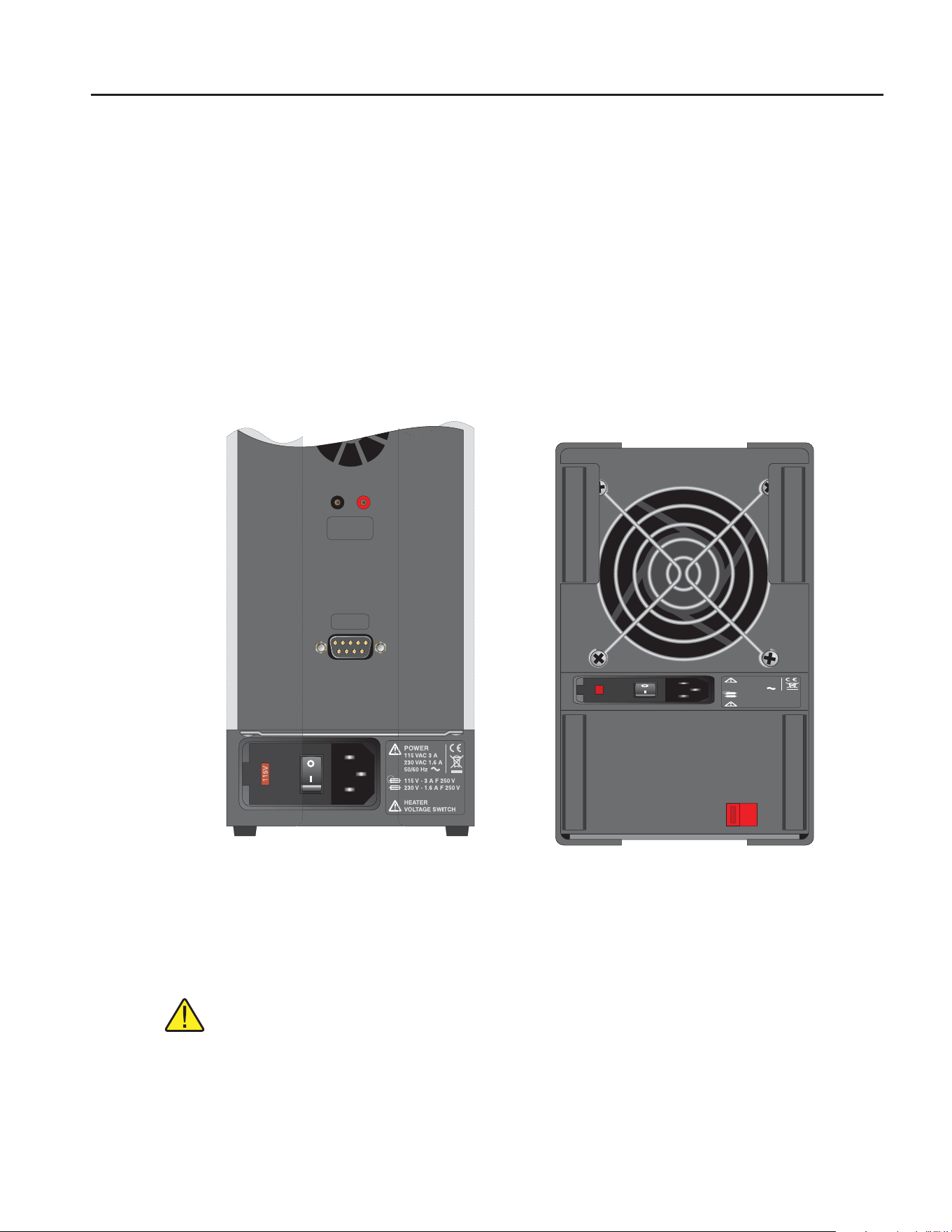
Back and Bottom Panel7.1
Refer to Figure 1 on this page.
Power Cord – Underneath the calibrator is the removable power cord inlet that plugs
into an IEC grounded socket.
Power Switch – The power switch is located on the power entry module (PEM). The
PEM also houses the fuses and the dual voltage selector. The PEM and Heater Voltage
Switch (see below) allow the unit to be field switchable for 115 VAC (±10%) or 230
VAC (±10%) operation.
115V
115
V
HEATER
VOLTAGE SWITCH
115V
HEATER
VOLTAGE SWITCH
115 VAC 3 A
230 VAC 1.6 A
50/60 Hz
115 V - 3 250 V
230 V - 250 V
A F
1.6 A
F
POWER
DISPLAY
HOLD
RS-232
HEATER
VOLTAGE SWITCH
115 VAC 3 A
230 VAC 1.6 A
50/60 Hz
115 V - 3 250 V
230 V - 250 V
A F
1.6 A
F
POWER
Back View Bottom View
Figure 1 6102 Back Panel and Bottom
Heater Voltage Switch – To be used only when changing the input voltage. (See
Section 8.1 for instructions on changing the input voltage.)
Caution: The input voltage and heater voltage switch settings should al ways be
the same value.
Serial Port – A DB-9 male connector is present for interfacing the calibrator to a
computer or terminal with serial RS-232 communications.
1.888.610.7664 sales@GlobalTestSupply.com
Fluke-Direct.com
6102 Micro-Bath User’s Guide
Front Panel
18
Fan – The fan inside the calibrator runs continuously when the unit is being op erated
to provide cooling for the instrument. Slots at the top and around the two cor ners of
the calibrator are provided for airÀow. The area around the calibrator must be kept
clear to allow adequate ventilation. The airÀow is directed out the back.
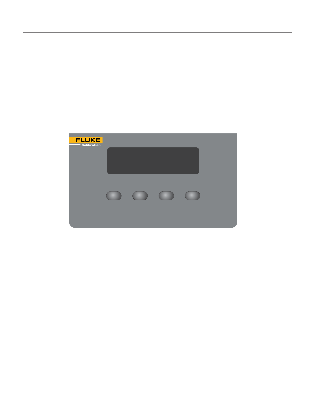
Front Panel7.2
Refer to Figure 2 on this page.
Controller Display – The digital display is an important part of the temperature
controller because it not only displays set and actual temperatures but also dis plays
various calibrator functions, settings, and constants. The display shows temperatures
in units according to the selected scale °C or °F.
6102 Front PanelFigure 2
Controller Keypad – The four button keypad allows easy setting of the set-point
temperature. The control buttons (SET, DOWN, UP, and EXIT) are used to set the
calibrator temperature set-point, access and set other operating parameters, and access
and set calibration parameters.
Setting the control temperature is done directly in degrees of the current scale. It can
be set to 0.01 degrees Celsius or Fahrenheit.
The functions of the buttons are as follows:
SET – Used to display the next parameter in the menu and to store parameters to the
displayed value.
DOWN – Used to decrement the displayed value of parameters.
UP – Used to increment the displayed value.
EXIT – Used to exit a function and to skip to the next function. Any changes to the
displayed value are ignored. Holding the EXIT button for approximately 0.5 seconds
exits back to the main display.
SET
UP
DOWN EXIT
200.00C
MICRO-BATH 35°C to 200°C
6102
1.888.610.7664 sales@GlobalTestSupply.com
Fluke-Direct.com
19
Parts and Controls
Accessories
Accessories 7.3
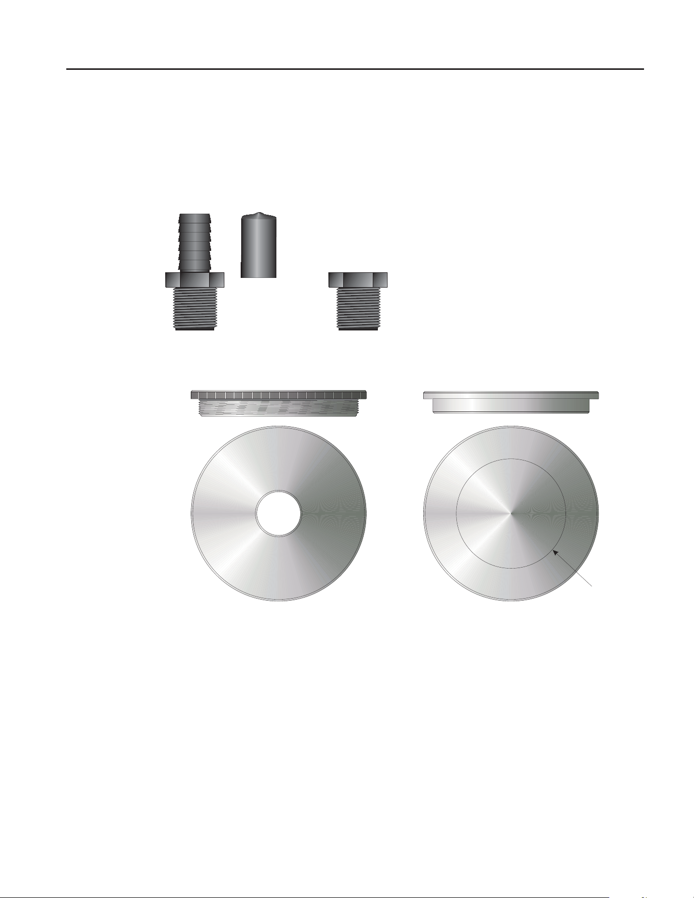
Transport/Pour Lid 7.3.1
A transport/pour lid (Figure 3) is provided so the fluid being used does not have to be
removed when transporting. The lid doubles as a pour spout.
Figure 3
Pour Spout
Pour Spout
Cover
Transport
Plug
Transport/Pour Lid
Aluminum
Access Cover
(optional)
Guide Ring
Bath Lids and Lid Parts
Access Cover (Optional) 7.3.2
An aluminum access cover (Figure 3) may be purchased for optimum stability. Holes
should be drilled in the access cover to allow insertion of the probes into the tank. The
holes must be within the guide ring for the probes to fit into the probe basket.
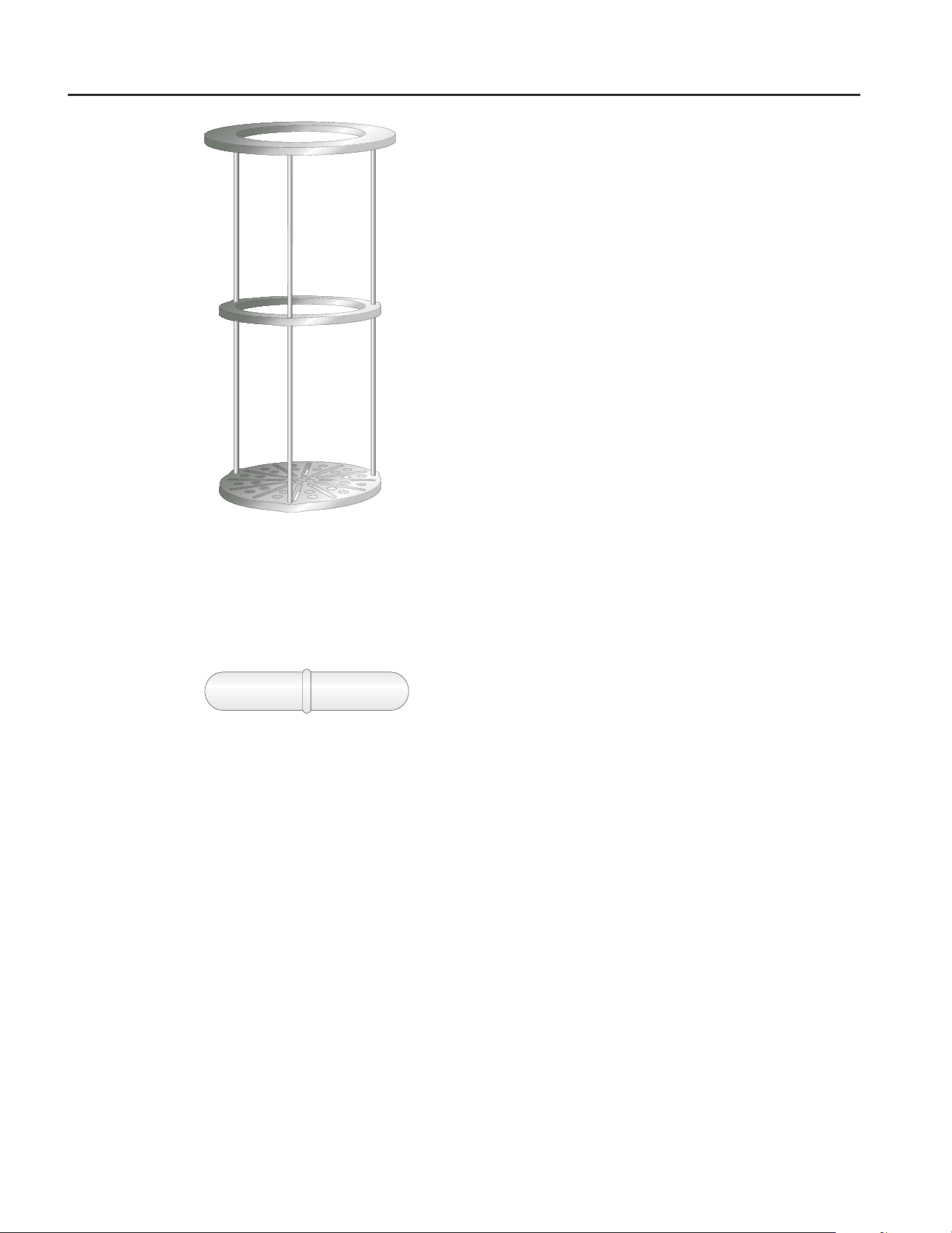
Probe Basket 7.3.3
A probe basket (Figure 4) is provided as a guide for the probes and to prevent bumping
of the stir bar.
1.888.610.7664 sales@GlobalTestSupply.com
Fluke-Direct.com
6102 Micro-Bath User’s Guide
Accessories
20
Figure 4 Probe Basket
Stir Bar 7.3.4
The stir bar (Figure 5) sits in the bottom of the well for mixing the fluid provid ing
better accuracy, uniformity, and stability.
Figure 5 Stir Bar
Tank Extender (Optional) 7.3.5
An optional tank extender is available for increasing the depth of the tank. The
stability and the uniformity of the bath may change when using the extender. The
extender screws onto the tank and is equipped with an O-ring. Thread the extender
down, using the wrench, until the O-ring makes a good seal.
Some fluids may expand up to 6.35 cm (2.5 inches). Therefore, when using the tank
extender keep in mind how much the fluid will expand. Do not overfill the tank.
Ensure that the tank extender does not leak where the tank extender and the tank meet.
Do not use the extender without the perf-cage placed over the extender. Do not leave
the 6102 unattended while operating.
Cool the bath to ambient and remove all fluid from the bath before removing the
extender.
1.888.610.7664 sales@GlobalTestSupply.com
Fluke-Direct.com

21
General Operation
Switching to 230V Operation
General Operation8
8.1 Switching to 230V Operation
The 6102 is switchable from 115 VAC to 230 VAC 50/60 Hz. Swithcing the voltage
can change the calibration, so the unit should be calibrated after changing the input
voltage.
To change from 115 VAC to 230 VAC:
Unplug the unit. 1.
Lay the unit down on its side. 2.
With a small straight slot screwdriver remove the fuse holder located on the 3.
bottom of the bath. Replace the two fuses (3 amp 250 V) with 1.6 amp 250 V
fuses.
Replace the fuse holder with the “230V” in the display window. 4.
Using the same straight slot screwdriver, move the heater switch to dis play 5.
“230V”. See the back panel and bottom drawing in Figure 1 on page 17.
Caution: The input voltage and heater voltage switch settings must both read
230V when complete. Otherwise, the unit will either not heat or only heat at a
fraction of its capacity. If not done properly, the unit could become damaged and
void the calibration and warranty. Use 3 amp fuses for 115 V and 1.6 amp for
230 V only. Do not plug the unit into 230 V if the heater switch and fuse holder
read 115 V. This will cause the fuses to blow and may damage the instrument.
8.2 Bath Fluid
Many fluids work with the 6102 bath. Choosing a fluid requires consideration of many
important characteristics of the fluid. Among these are temperature range, viscosity,
specific heat, thermal conductivity, thermal expansion, electri cal resistivity, fluid
lifetime, safety, and cost.
Caution: DO NOT exceed the boiling or flash point of the fluid.
Temperature Range8.2.1
One of the most important characteristics to consider is the temperature range of the
fluid. Few fluids work well throughout the complete temperature range of the bath.
The temperature at which the bath is operated must always be within the safe and
useful temperature range of the fluid. The lower tempera ture range of the fluid is
determined by the freeze point of the fluid or the tem perature at which the viscosity
becomes too great. The upper temperature is usually limited by vaporization,
flammability, or chemical breakdown of the fluid. Vaporization of the fluid at higher
temperatures may affect temperature stability because of cool condensed fluid dripping
into the bath from the lid.
1.888.610.7664 sales@GlobalTestSupply.com
Fluke-Direct.com

6102 Micro-Bath User’s Guide
Bath Fluid
22
Viscosity8.2.2
Viscosity is a measure of the thickness of a fluid, how easily it can be poured and
mixed. Viscosity affects the temperature stability of the bath. With low vis cosity,
fluid mixing is better which creates a more uniform temperature throughout the bath.
This improves the bath response time which allows it to maintain a more constant
temperature. For good control the viscosity should be less than ten centistokes. Twenty
centistokes is about the upper limit of allow able viscosity. Viscosities greater than this
cause very poor control stability and may also overheat or damage the stirring motor.
Oil viscosity may vary greatly with temperature.
When using fluids with higher viscosities the controller proportional band may need to
be increased to compensate for the reduced response time. Otherwise the temperature
may begin to oscillate.
Specic Heat8.2.3
Specific heat is the measure of the heat storage ability of the fluid. Specific heat, to a
small degree, affects the control stability. It also affects the heating and cooling rates.
Generally, a lower specific heat means quicker heating and cooling. The proportional
band may require some adjustment depending on the specific heat of the fluid.
Thermal Conductivity8.2.4
Thermal conductivity measures how easily heat flows through the fluid. Ther mal
conductivity of the fluid affects the control stability, temperature unifor mity, and probe
temperature settling time. Fluids with higher conductivity distribute heat more quickly
and evenly improving bath performance.
Thermal Expansion8.2.5
Thermal expansion describes how the volume of the fluid changes with temper ature.
Thermal expansion of the fluid used must be considered since the in crease in fluid
volume as the bath temperature changes may cause overflow. Excessive thermal
expansion may also be undesirable in applications where constant liquid level is
important. Many fluids including oils have significant thermal expansion.
Electrical Resistivity8.2.6
Electrical resistivity describes how well the fluid insulates against the flow of electric
current. In some applications, such as measuring the resistance of bare temperature
sensors, it may be important that little or no electrical leakage oc cur through the fluid.
In such conditions choose a fluid with very high resistivity.
1.888.610.7664 sales@GlobalTestSupply.com
Fluke-Direct.com

23
General Operation
Bath Fluid
Fluid Lifetime8.2.7
Many fluids degrade over time because of evaporation, water absorption, gel ling,
or chemical breakdown. Often the degradation becomes significant near the upper
temperature limit of the fluid, substantially reducing the fluid’s lifetime.
8.2.8 Safety
When choosing a fluid always consider the safety issues associated. Obviously
where there are conditions of extreme hot or cold there can be danger to people and
equipment. Fluids may also be hazardous for other reasons. Some fluids may be
considered toxic. Contact with eyes, skin, or inhalation of vapors may cause injury. A
proper fume hood must be used if hazardous or bothersome va pors are produced.
Warning: Fluids at high temperatures may pose danger from BURNS, FIRE,
and TOXIC FUMES. Use appropriate caution and safety equip ment.
Fluids may be flammable and require special fire safety equipment and proce dures.
An important characteristic of the fluid to consider is the flash point. The flash point
is the temperature at which there is sufficient vapor given off so that when there is
sufficient oxygen present and a ignition source is applied the va por will ignite. This
does not necessarily mean that fire will be sustained at the flash point. The flash point
may be either of the open cup or closed cup type. Either condition may occur in a bath
situation. The closed cup temperature is always the lower of the two. The closed cup
represents the contained vapors in side the tank and the open cup represents the vapors
escaping the tank. Oxygen and an ignition source will be less available inside the tank.
Environmentally hazardous fluids require special disposal according to applica ble
federal or local laws after use.
Cost8.2.9
Cost of bath fluids may vary greatly, from cents per gallon for water to hun dreds of
dollars per gallon for synthetic oils. Cost may be an important consid eration when
choosing a fluid.
Commonly Used Fluids8.2.10
Below is a description of some of the more commonly used fluids and their
characteristics.
1.888.610.7664 sales@GlobalTestSupply.com
Fluke-Direct.com

6102 Micro-Bath User’s Guide
Bath Fluid
24
Water (Distilled) 8.2.10.1
Water is often used because of its very low cost, availability, and excellent tem perature
control characteristics. Water has very low viscosity and good thermal conductivity
and heat capacity which makes it among the best fluids for control stability at low
temperatures. Temperature stability is much poorer at higher temperatures because
water condenses on the lid, cools and drips into the bath. Water is safe and relatively
inert. The electrical conductivity of water may pre vent its use in some applications.
Water has a limited temperature range, from a few degrees above 0°C to a few degrees
below 100°C. At higher temperatures evaporation becomes significant. Water used in
the bath should be distilled or softened to prevent mineral deposits. Consider using an
algaecide chemical in the water to prevent contamination.
Mineral Oil8.2.10.2
Mineral oil or paraffin oil is often used at moderate temperatures above the range
of water. Mineral oil is relatively inexpensive. At lower temperatures mineral oil
is quite viscous and control may be poor. At higher temperatures vapor emission
becomes significant. The vapors may be dangerous and use of a fume hood is highly
recommended. As with most oils mineral oil will expand as temperature increases
so be careful not to fill the bath too full that it over flows when heated. The viscosity
and thermal characteristics of mineral oil is poorer than water so temperature stability
will not be as good. Mineral oil has very low electrical conductivity. Use caution
with mineral oil since it is flammable and may also cause serious injury if inhaled or
ingested.
Silicone Oil (Dow Corning 200.10, 200.20)8.2.10.3
Silicone oils are available which offer a much wider operating temperature range than
mineral oil. Like most oils, silicone oils have temperature control characteristics which
are somewhat poorer than water. The viscosity changes significantly with temperature
and thermal expansion also occurs. These oils have very high electrical resistivity.
Silicone oils are fairly safe and non-toxic. Silicone oils are fairly expensive.
Fluid Characteristics Charts8.2.11
Table 3 on page 25 and Figure 6 on page 26 have been created to provide help in
selecting a heat exchange fluid media for your constant temperature bath. These charts
provide both a visual and numerical representation of most of the physical qualities
important in making a selection. The list is not all inclusive. There may be other useful
fluids not shown in this listing.
The charts include information on a variety of fluids which are often used as heat
transfer fluid in baths. Because of the temperature range some fluids may not be useful
with your bath.
1.888.610.7664 sales@GlobalTestSupply.com
Fluke-Direct.com

25
General Operation
Bath Fluid
Limitations and Disclaimer 8.2.11.1
The information given in this manual regarding fluids is intended only to be used as
a general guide in choosing a fluid. Though every effort has been made to provide
correct information we cannot guarantee accuracy of data or assure suitability of a
fluid for a particular application. Specifications may change and sources sometimes
offer differing information. Hart Scientific cannot be liable for any personal injury or
damage to equipment, product or facilities resulting from the use of these fluids. The
user of the bath is responsible for collecting correct information, exercising proper
judgment, and insuring safe operation. Operating near the limits of certain properties
such as the flash point or viscos ity can compromise safety or performance. Your
company’s safety policies re garding flash points, toxicity, and such issues must be
considered. You are responsible for reading the MSDS (material safety data sheets)
and acting accordingly.
Table 3 Table of Various Bath Fluids
Fluid
(# = Hart
Part No.)
Lower
Temperature
Limit *
Upper
Temperature
Limit *
Flash
Point
Viscosity
(centistokes)
Specic
Gravity
Specic
Heat
(cal/g/°C)
Thermal
Conductivity
(cal/s/cm/°C)
Thermal
Expansion
(cm/cm/°C)
Resistivity
(10
12
:-cm )
Halocarbon
0.8
#5019
-100°C (v) ** 70°C (e) NONE 5.7 @ -50°C
0.8 @ 40°C
0.5 @ 70°C
1.71 @ 40°C 0.2 0.0004 0.0011
Methanol -96°C (fr) 10°C (, cc) 12°C 1.3 @ -35°C
0.66 @ 0°C
0.45 @ 20°C
0.810 @ 0°C
0.792 @ 20°C
0.6 0.0005 @ 20°C 0.0014 @ 25°C
Water 0°C (fr) 95°C (b) NONE 1 @ 25°C
0.4 @ 75°C
1.00 1.00 0.0014 0.0002 @ 25°C
Ethylene
Glycol-50%
#5020
-30°C (fr) 90°C (b) NONE 7 @ 0°C
2 @ 50°C
0.7 @ 100°C
1.05 0.8 @ 0°C 0.001
Mineral Oil
No. 7 #5011
10°C (v) 166°C () 168°C 15 @ 75°C
5 @ 125°C
0.87 @ 25°C
0.84 @ 75°C
0.81 @ 125°C
0.48 @ 25°C
0.53 @ 75°C
0.57 @ 125°C
0.00025 @ 25°C 0.0007 @ 50°C 5 @ 25°C
Silicone Oil
Type 200.05
#5010
-40°C (v) ** 130°C (, cc) 133°C 5 @ 25°C 0.92 @ 25°C 0.4 0.00028 @ 25°C 0.00105 1000 @ 25°C
10 @ 150°C
Silicone Oil
Type 200.10
#5012
-30°C (v) ** 209°C (, cc) 211°C 10 @ 25°C
3 @ 135°C
0.934 @ 25°C 0.43 @ 40°C
0.45 @ 100°C
0.482 @ 200°C
0.00032 @ 25°C 0.00108 1000 @ 25°C
50 @ 150°C
Silicone Oil
Type 200.20
#5013
10°C (v) 230°C (, cc) 232°C 20 @ 25°C 0.949 @ 25°C 0.370 @ 40°C
0.393 @ 100°C
0.420 @ 200°C
0.00034 @ 25°C 0.00107 1000 @ 25°C
50 @ 150°C
Silicone Oil
Type 200.50
#5014
30°C (v) 278°C (, cc) 280°C 50 @ 25°C 0.96 @ 25°C 0.4 0.00037 @ 25°C 0.00104 1000 @ 25°C
50 @ 150°C
Silicone Oil
Type 550
#5016
70°C (v) 230°C (, cc)
300°C (, oc)
232°C 50 @ 70°C
10 @ 104°C
1.07 @ 25°C 0.358 @ 40°C
0.386 @ 100°C
0.433 @ 200°C
0.00035 @ 25°C 0.00075 100 @ 25°C
1 @ 150°C
Silicone Oil
Type 710
#5017
80°C (v) 300°C (, oc) 302°C 50 @ 80°C
7 @ 204°C
1.11 @ 25°C 0.363 @ 40°C
0.454 @ 100°C
0.505 @ 200°C
0.00035 @ 25°C 0.00077 100 @ 25°C
1 @ 150°C
Silicone Oil
Type 210-H
66°C (v) 313°C (, oc) 315°C 50 @ 66°C
14 @ 204°C
0.96 @ 25°C 0.34 @ 100°C 0.0003 0.00095 100 @ 25°C
1 @ 150°C
Heat Transfer
Salt #5001
180°C (fr) 550°C NONE 34 @ 150°C
6.5 @ 300°C
2.4 @ 500°C
2.0 @ 150°C
1.9 @ 300°C
1.7 @ 500°C
0.33 0.0014 0.00041 1.7 :/cm
3
*Limiting Factors — b – boiling point e – high evaporation – ash point fr – freeze point v – viscosity — Flash point test oc = open cup cc = closed cup
**Very low water solubility, ice will form as a slush from condensation below freezing.
1.888.610.7664 sales@GlobalTestSupply.com
Fluke-Direct.com
6102 Micro-Bath User’s Guide
Bath Fluid
26
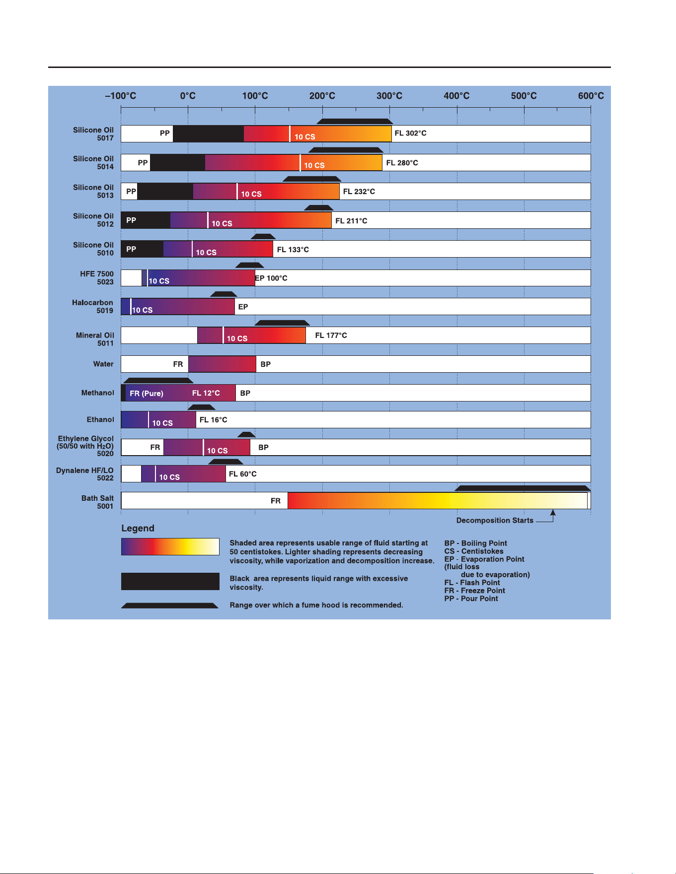
Figure 6 Chart of Various Bath Fluids
About the Graph 8.2.11.2
The fluid graph visually illustrates some of the important qualities of the fluids shown.
Temperature Range: The temperature scale is shown in degrees Celsius. The fluids’
general range of application is indicated by the shaded bands. Qualities including pour
point, freeze point, important viscosity points, flash point, boil ing point and others
may be shown.
1.888.610.7664 sales@GlobalTestSupply.com
Fluke-Direct.com

27
General Operation
Stirring
Freezing Point: The freezing point of a fluid is an obvious limitation to stir ring. As
the freezing point is approached high viscosity may also limit performance.
Pour Point: This represents a handling limit for the fluid.
Viscosity: Points shown are at 50 and 10 centistokes viscosity. When viscosity is
greater than 50 centistokes stirring is very poor and the fluid is unsatisfactory for bath
applications. Optimum stirring generally occurs at 10 centistokes and below.
Fume Point: A fume hood should be used. This point is very subjective in na ture and
is impacted by individual tolerance to different fumes and smells, how well the bath is
covered, the surface area of the fluid in the bath, the size and ventilation of the facility
where the bath is located and other conditions. We as sume the bath is well covered at
this point. This is also subject to company policy.
Flash Point: The point at which ignition may occur. The point shown may be either
the open or closed cup flash point. Refer to the flash point discussion in Section 8.2.8.
Boiling Point: At or near the boiling point of the fluid, the temperature stabil ity is
difficult to maintain. Fuming or evaporation is excessive. Large amounts of heater
power may be required because of the heat of vaporization.
Decomposition: The temperature may reach a point at which decomposition of the
fluid begins. Further increasing the temperature may accelerate decomposi tion to the
point of danger or impracticality.
Stirring 8.3
Stirring of the bath fluid is very important for stable temperature control. Prior to
taking measurements, always make sure that the bath is stirring the fluid. The fluid
must be mixed well for good temperature uniformity and fast controller response. The
stirrer is adjusted for optimum performance. Table 4 on page 28 shows nominal stirrer
motor settings for several fluids.
Note: If the bath is used with the probe basket removed, stir motor settings need
to be changed so that a small vortex can be seen in the liquid. If any water is
mixed with oil when exceeeding temperatures of 90°C the bath will boil over.
Warning: Do not mix water and oil when exceeding temperatures of 90°C
1.888.610.7664 sales@GlobalTestSupply.com
Fluke-Direct.com

6102 Micro-Bath User’s Guide
Power
28
Table 4 Nominal Stirrer Motor Settings With Different Liquids
Liquid Boiling/Flash Point Stir Motor Setting Temperature
Distilled Water/
Ethylene Glycol
100°C 15 25°C to 80°C
(77°F to 176°F)
200.10 Oil 165°C 25 80°C to 140°C
(176°F to 284°F)
200.20 Oil 133°C 20 130°C to 200°C
(266°F to 392°F)
Power8.4
Power to the bath is provided by an AC mains supply and passes through a filter to
prevent switching spikes from being transmitted to other equipment. Re fer to Section
3.1, Specifications, for power details.
To turn on the bath, switch the control panel power switch to the ON position. The stir
motor will turn on, the LED display will begin to show the bath tem perature, and the
heater will turn on or off until the bath temperature reaches the programmed set-point.
When powered on the control panel display will briefly show a four digit num ber. This
number indicates the number of times power has been applied to the bath. Also briefly
displayed is data which indicates the controller hardware configuration. This data is
used in some circumstances for diagnostic purposes.
Heater8.5
The power to the bath is precisely controlled by the temperature controller to maintain
a constant bath temperature. Power is controlled by periodically switching the heater
on for a certain amount of time using a solid-state relay.
Fluid Drain8.6
The fluid may be drained from the 6102 by tightly screwing the transport/pour lid onto
the top of the bath and pouring the liquid into an appropriate container.
Temperature Controller 8.7
The bath temperature is controlled by Hart Scientific’s unique hybrid digi tal/analog
temperature controller. The controller offers the tight control stability of an analog
temperature controller as well as the flexibility and programmabil ity of a digital
controller.
The bath temperature is monitored with a platinum resistance sensor in the con trol
probe. The signal is electronically compared with the programmable refer ence signal,
amplified, and then fed to a pulse-width modulator circuit which controls the amount
of power applied to the bath heater.
1.888.610.7664 sales@GlobalTestSupply.com
Fluke-Direct.com

29
General Operation
Temperature Controller
The bath is operable within the temperature range given in the specifications. For
protection against solid-state relay failure or other circuit failure, a bi-me tallic cutout
automatically turns off the heater anytime the bath temperature exceeds the maximum
temperature.
The controller allows the operator to set the bath temperature with high resolu tion,
adjust the proportional band, monitor the heater output power, and pro gram the
controller configuration and calibration parameters. The controller may be operated
in temperature units of degrees Celsius or Fahrenheit. The controller is operated and
programmed from the front control panel using the four key switches and digital LED
display. The controller is equipped with a serial RS-232 digital interface for remote
operation. Operation of the controller using the front control panel is discussed in
Section 9. Operation using the digital interfaces is discussed in Section 10.
When the controller is set to a new set-point the bath heats or cools to the new
temperature. Once the new temperature is reached the bath usually takes 15 – 20
minutes for the temperature to settle and stabilize. There may be a small over shoot or
undershoot.
1.888.610.7664 sales@GlobalTestSupply.com
Fluke-Direct.com

1.888.610.7664 sales@GlobalTestSupply.com
Fluke-Direct.com

31
Controller Operation
Well Temperature
9 Controller Operation
This chapter discusses in detail how to operate the bath temperature controller using
the front control panel. Using the front panel key-switches and LED dis play the user
may monitor the well temperature, set the temperature set-point in degrees C or F,
monitor the heater output power, adjust the controller propor tional band, and program
the calibration parameters, operating parameters, and serial interface configuration.
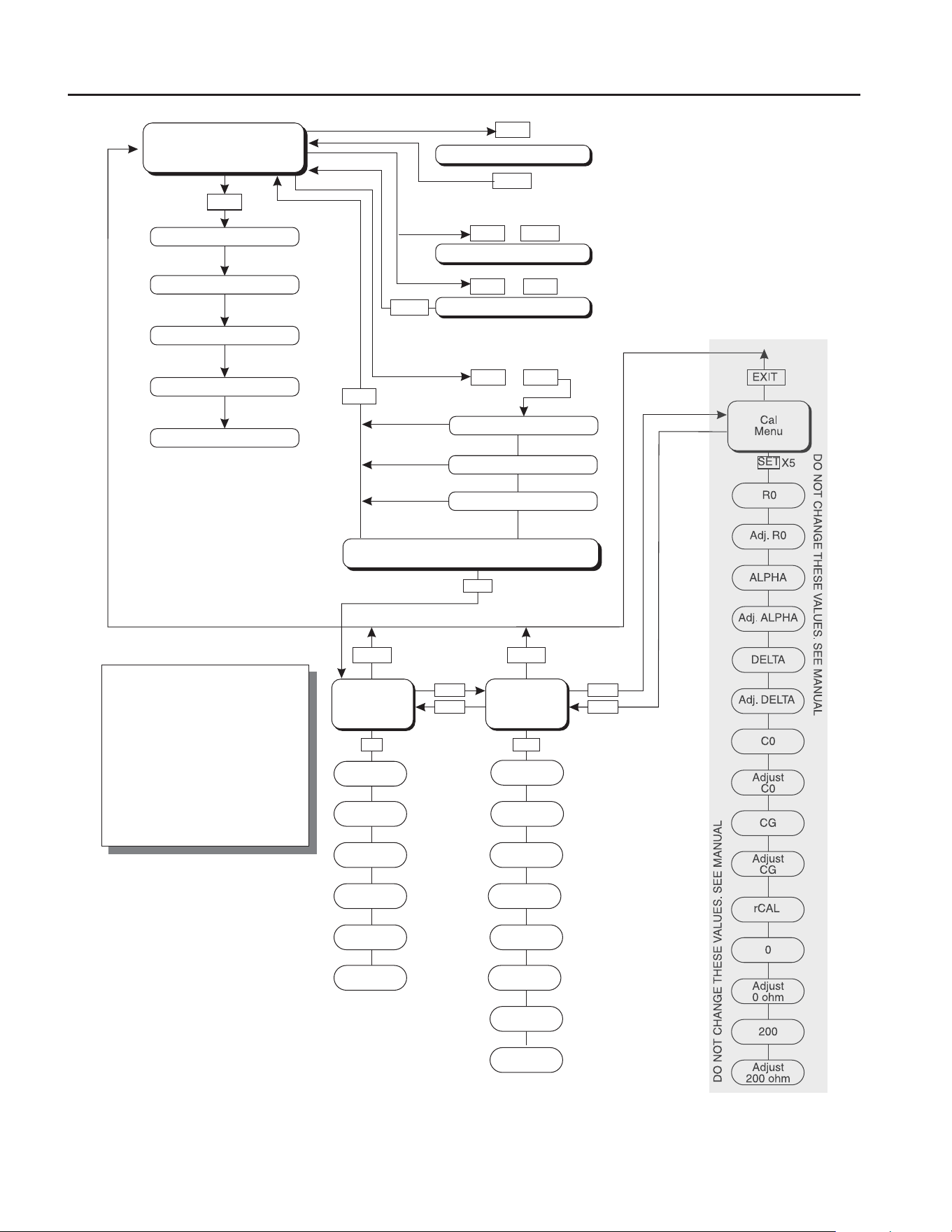
Operation of the functions and parameters are shown in the flowchart in Figure 7 on
page 32. This chart may be copied for reference.
In the following discussion a button with the word SET, UP, DOWN or EXIT
inside indicates the panel button while the dotted box indicates the display reading.
Explanation of the button or display reading are to the right of each button or display
value.
Well Temperature 9.1
The digital LED display on the front panel allows direct viewing of the actual well
temperature. This temperature value is what is normally shown on the dis play. The
units, C or F, of the temperature value are displayed at the right. For example,
100.00C
Well temperature in degrees Celsius
The temperature display function may be accessed from any other function by pressing
the “EXIT” button.
9.2 Temperature Set-point
The temperature set-point can be set to any value within the range and resolu tion as
given in the specifications. Be careful not to exceed the safe upper tem perature limit of
any device inserted into the well.
Setting the temperature involves selecting the set-point memory and adjusting the set-
point value.
Programmable Set-points 9.2.1
The controller stores 8 set-point temperatures in memory. The set-points can be
quickly recalled to conveniently set the calibrator to a previously programmed
temperature set-point.
To set the temperature one must first select the set-point memory. This function is
accessed from the temperature display function by pressing “SET”. The number of the
set-point memory currently being used is shown at the left on the display followed by
the current set-point value.
1.888.610.7664 sales@GlobalTestSupply.com
Fluke-Direct.com
6102 Micro-Bath User’s Guide
Temperature Set-point
32
Figure 7
UP
UP
DOWN DOWN
SET
Operating
Parameters
Menu
SET
SET
Cal
Menu
ALPHA
DELTA
Adj. R0
DO NOT CHANGE THESE VALUES. SEE MANUAL
DO NOT CHANGE THESE VALUES. SEE MANUAL
Adj. ALPHA
Serial
Interface
Menu
BAUD
Rate
Adjust
BAUD Rate
Sample
Period
High
Limit
Adj. Sample
Period
Adj. High
Limit
Duplex
Mode
Cut-out
Reset
Adj. Duplex
Mode
Adj. Cut-out
Reset
Linefeed
C0
0
Adjust
Linefeed
Adjust
C0
Adjust
0 ohm
CG
200
Adjust
CG
Adjust
200 ohm
EXITEXIT
EXIT
EXIT
EXIT
UP
DOWN
DOWN
SET
SET
SET
UP
+
+
+
Display Power
Toggles °C / °F
SET
SET
Select Setpoint
Adjust Setpoint
Units °C/°F
Scan On/Off
Scan Rate
Display
Temperature
Configuration Menu
Secondary Functions
X5
Stir
Speed
Adj. Stir
Speed
Toggles Display of Rs
Switch Hold Display Mode
EXIT
Set Proportional Band
Cut-out
R0
Adj. DELTA
rCAL
Menu Legend:
Press “SET” to step through the
menu and to store the parameter
value.
Press “EXIT” briefly to skip a
parameter without storing the
parameter value.
Hold “EXIT” to exit the menu and
display the temperature
Controller Operation Flowchart
1.888.610.7664 sales@GlobalTestSupply.com
Fluke-Direct.com

33
Controller Operation
Temperature Set-point
100.00C
Well temperature in degrees Celsius
2
Access set-point memory
1. 25
Set-point memory 1, 25°C currently used
To change the set-point memory press “UP” or “DOWN”.
4. 125.
New set-point memory 4, 125°C
Press “SET” to accept the new selection and access the set-point value.
2
Accept selected set-point memory
Set-point Value 9.2.2
The set-point value may be adjusted after selecting the set-point memory and pressing
“SET”.
4 125.
Set-point 4 value in °C
If the set-point value is correct, hold “EXIT” to resume displaying the well
temperature. Press “UP” or “DOWN” to adjust the set-point value.
125.00
New set-point value
When the desired set-point value is reached press “SET” to accept the new value and
access the temperature scale units selection. If “EXIT” is pressed in stead of “SET”,
any changes made to the set-point are ignored.
2
Accept new set-point value
Temperature Scale Units 9.2.3
The temperature scale units of the controller can be set by the user to degrees Celsius
(°C) or Fahrenheit (°F). The selected units are used in displaying the well temperature,
set-point, and proportional band.
Press “SET” after adjusting the set-point value to change display units.
Un= C
Scale units currently selected
Press “UP” or “DOWN” to change the units.
1.888.610.7664 sales@GlobalTestSupply.com
Fluke-Direct.com

6102 Micro-Bath User’s Guide
Scan
34
Un= F
New units selected
Scan 9.3
The scan rate can be set and enabled so that when the set-point is changed the bath
heats or cools at a specified rate (degrees per minute) until it reaches the new set-point.
With the scan disabled the bath heats or cools at the maximum possible rate.
9.3.1 Scan Control
The scan is controlled with the scan on/off function that appears in the main menu
after the set-point function.
Sc=OFF
Scan function off
Press “UP” or “DOWN” to toggle the scan on or off.
Sc=On
Scan function on
Press “SET” to accept the present setting and continue.
2
Accept scan setting
9.3.2 Scan Rate
The next function in the main menu is the scan rate. The scan rate can be set from
.1 to 99.9°C/min. The maximum scan rate however is actually limited by the natural
heating or cooling rate of the instrument. This is often less than 100°C/min, especially
when cooling.
The scan rate function appears in the main menu after the scan control function. The
scan rate units are in degrees C per minute.
Sr= 10.0
Scan rate in°C/min
Press “UP” or “DOWN” to change the scan rate.
Sr= 2.0
New scan rate
Press “SET” to accept the new scan rate and continue.
2
Accept scan rate
1.888.610.7664 sales@GlobalTestSupply.com
Fluke-Direct.com

35
Controller Operation
Temperature Display Hold
Temperature Display Hold 9.4
The 6102 has a display hold function which allows action of an external switch to
freeze the displayed temperature and stop the set-point from scanning. This is useful
for testing thermal switches and cutouts. This section ex plains the functions available
for operating the temperature hold feature. An ex ample follows showing how to set up
and use the hold feature to test a switch.
Hold Temperature Display 9.4.1
The hold feature is enabled by simply pressing the “UP” button when the tem perature
is displayed. The hold temperature display shows the hold temperature on the right
and the switch status on the left. For the status “c” means the switch is closed and “o”
means the switch is open. The status flashes when the switch is in its active position
(opposite the normal position). The hold temper ature shows what the temperature of
the well was when the switch changed from its normal position to its active position.
While the switch is in the normal position the hold temperature will follow the well
temperature.
If the Scan Control is “OFF” and the Hold Temperature Display is being used, the
temperature at which the switch is activated does not affect the set-point temperature.
However, if the Scan Control is “ON” and the Hold Temperature Display is being
used, the temperature at which the switch is activated is stored as the new set-point
temperature.
Operation of the hold temperature display is outlined below.
143.50C
Well temperature display
4
Access hold display
c 144.8
Switch status and hold temperature
To return to the normal well temperature display press “DOWN”.
Mode Setting 9.4.2
The Hold Function is always in the automatic mode. In this mode the normal position
is set to whatever the switch position is when the set-point is changed. For example,
if the switch is currently open when the set-point is changed, the closed position
then becomes the new active position. The normal position will be set automatically
under any of the following conditions, (1) a new set-point number is selected, (2)
the set-point value is changed, (3) a new set-point is set through the communications
channels.
1.888.610.7664 sales@GlobalTestSupply.com
Fluke-Direct.com

6102 Micro-Bath User’s Guide
Secondary Menu
36
Switch Wiring 9.4.3
The thermal switch or cutout is wired to the calibrator at the two terminals on the back
of the Micro-Bath labeled “DISPLAY HOLD”. The switch wires may be connected
to the terminals either way. Internally the black terminal connects to ground. The
red terminal connects to +5V through a 100 k: resistor. The calibrator measures the
voltage at the red terminal and interprets +5V as open and 0V as closed.
Switch Test Example 9.4.4
This section describes a possible application for the temperature hold feature and how
the instrument is set up and operated.
Suppose you have a thermal switch which is supposed to open at about 75°C and close
at about 50°C and you want to test the switch to see how accurate and repeatable it
is. You can use the temperature hold feature and the scan function to test the switch.
Measurements can be made by observing the display or, pref erably, by collecting data
using a computer connected to the RS-232 port. To set up the test do the following
steps.
Connect the switch wires to the terminals on the back of the Micro-Bath and 1.
place the switch in the well.
Enable set-point scanning by setting the scan to “ON” in the primary menu (2. see
Section 9.3.1).
Set the scan rate to a low value, say 1.0°C/min. (3. see Section 9.3.2). If the
scan rate is too high you may lose accuracy because of transient temperature
gradients. If the scan rate is too low the duration of the test may be longer than
is necessary. You may need to experiment to find the best scan rate.
Set the first program set-point to a value above the expected upper switch 4.
temperature, say 90°C.
Set the second program set-point to a value below the expected lower switch 5.
temperature, say 40°C, in the program menu.
Collect data on a computer connected to the RS-232 port. Refer to 6. Section
9.11, Serial Interface Parameters, for instructions on configuring the RS-232
communications interface.
Secondary Menu 9.5
Functions which are used less often are accessed within the secondary menu. The
secondary menu is accessed by pressing “SET” and “EXIT” simulta neously and then
releasing. The first function in the secondary menu is the heater power display. (See
Figure 7 on page 32.)
1.888.610.7664 sales@GlobalTestSupply.com
Fluke-Direct.com

37
Controller Operation
Heater Power
Heater Power9.6
The temperature controller controls the temperature of the well by pulsing the heater
on and off. The total power being applied to the heater is determined by the duty
cycle or the ratio of heater on time to the pulse cycle time. By knowing the amount of
heating the user can tell if the calibrator is heating up to the set-point, cooling down, or
controlling at a constant temperature. Monitoring the percent heater power will let the
user know how stable the well temperature is. With good control stability the percent
heating power should not fluctuate more than ±5% within one minute.
The heater power display is accessed in the secondary menu. Press “SET” and “EXIT”
simultaneously and release. The heater power will be displayed as a percentage of full
power.
100.00C
Well temperature
2
+
$
Access heater power in secondary menu
SEC
Flashes
12.0 P
Heater power in percent
To exit out of the secondary menu hold “EXIT”. To continue on to the propor tional
band setting function press “EXIT” momentarily or “SET”.
Proportional Band 9.7
In a proportional controller such as this the heater output power is proportional to the
well temperature over a limited range of temperatures around the set-point. This range
of temperature is called the proportional band. At the bot tom of the proportional band
the heater output is 100%. At the top of the pro portional band the heater output is 0.
Thus as the temperature rises the heater power is reduced, which consequently tends to
lower the temperature back down. In this way the temperature is maintained at a fairly
constant temperature.
The temperature stability of the well and response time depend on the width of
the proportional band. If the band is too wide the well temperature will deviate
excessively from the set-point due to varying external conditions. This is be cause the
power output changes very little with temperature and the controller cannot respond
very well to changing conditions or noise in the system. If the proportional band is too
narrow the temperature may swing back and forth be cause the controller overreacts to
temperature variations. For best control stabil ity the proportional band must be set for
the optimum width.
1.888.610.7664 sales@GlobalTestSupply.com
Fluke-Direct.com

6102 Micro-Bath User’s Guide
Cutout
38
The proportional band width is set at the factory to about 5.0°C. The propor tional band
width may be altered by the user if he desires to optimize the con trol characteristics
for a particular application.
The proportional band width is easily adjusted from the front panel. The width may
be set to discrete values in degrees C or F depending on the selected units. The
proportional band adjustment is be accessed within the secondary menu. Press “SET”
and “EXIT” to enter the secondary menu and show the heater power. Then press
“SET” to access the proportional band.
2
+
$
Access heater power in secondary menu
12.0 P
Heater power in percent
2
Access proportional band
ProP
Flashes “ProP” and the setting
5.0
Proportional band setting
To change the proportional band press “UP” or “DOWN”.
4.0
New proportional band setting
To store the new setting press “SET”. Press “EXIT” to continue without storing the
new value.
2
Accept the new proportional band setting
Cutout 9.8
As a protection against a hardware fault or user error, the calibrator is equipped with
an adjustable cutout device that shuts off power to the heater if the tank temperature
exceeds a set value. This protects the instrument and probes from excessive
temperatures. The cutout temperature is programmable by the opera tor from the front
panel of the controller.
The cutout for the 6102 Bath is defaulted to 225°C.
If the cutout is activated because of excessive temperatures, the heater shuts off and
the instrument cools. The tank cools until it reaches a few degrees below the cutout
set-point temperature. At this point, the action of the cutout is deter mined by the
setting of the cutout mode parameter. The cutout has two modes – automatic reset
or manual reset. If the mode is set to automatic, the cutout auto matically resets itself
when the temperature falls below the reset temperature al lowing the tank to heat up
1.888.610.7664 sales@GlobalTestSupply.com
Fluke-Direct.com

39
Controller Operation
Controller Conguration
again. If the mode is set to manual, the heater remains disabled until the user manually
resets the cutout.
The cutout set-point may be accessed within the secondary menu. Press “SET” and
“EXIT” simultaneously to enter the secondary menu. The heater power is displayed.
Press “SET” twice to access the cutout set-points.
cutout
Flashes “cutout” and then the setting
225
Cutout setting
To change the cutout setting press “UP” or “DOWN”.
100
New cutout setting
To store the new setting, press “SET”. Press “EXIT” to continue without stor ing the
new value.
Controller Conguration9.9
The controller has a number of configuration and operating options and calibra tion
parameters which are programmable via the front panel. These are ac cessed from the
secondary menu after the proportional band function by pressing “SET”. Pressing
“SET” again enters the first of three sets of configuration parameters: operating
parameters, serial interface parameters, and cali bration parameters. The menus are
selected using the “UP” and “DOWN” keys and then pressing “SET”. (See Figure 7
on page 32.)
Operating Parameters9.10
The operating parameters menu is indicated by,
PAr
Operating parameters menu
The operating parameters menu contains the Stir Speed, High Limit, and Cutout Reset
Mode parameters.
Stir Speed9.10.1
The Stir Speed parameter adjusts stirrer motor speed. The factory default is 15.
Str SP
Flashes “Str Sp” and then displays the setting
0
Current Stir Speed setting
To change the stir speed press “UP” or “DOWN”.
1.888.610.7664 sales@GlobalTestSupply.com
Fluke-Direct.com

6102 Micro-Bath User’s Guide
Operating Parameters
40
16
New Stir Speed setting
Press “SET” to accept the new Stir Speed.
The stir motor speed needs to be varied for best stability. Table 4 on page 28 shows
nominal settings for several fluids.
High Limit 9.10.2
The High Limit Parameter adjusts the upper set-point temperature. The factory default
and maximum temperature are set to 200°C. For safety, a user can ad just the High
Limit down so the maximum temperature set-point is restricted.
HL
High Limit parameter
Press “SET” to enable adjustment of the High Limit parameter.
HL
Flashes “HL” and then displays the setting
H=126
Current HL setting
Adjust the HL parameter using the “UP” or “DOWN” keys.
H=90
New HL setting
To store the new setting, press “SET”. Press “EXIT” to continue without storing the
new value.
Cutout Reset Mode9.10.3
The Cutout Reset Mode determines whether the cutout resets automatically when the
tank temperature drops to a safe value or must be manually reset by the operator.
CtorSt
Cutout Reset Mode parameter
Press “SET” to enable adjustment of the Cutout Reset Mode parameter. Nor mally, the
cutout is set for manual mode.
CtorSt
Flashes “CtorSt” and then displays the setting
rst
Cutout set for manual reset
To change to automatic reset mode press “UP” and then “SET”.
Auto
Cutout set for automatic reset
1.888.610.7664 sales@GlobalTestSupply.com
Fluke-Direct.com

41
Controller Operation
Serial Interface Parameters
To store the new setting, press “SET”. Press “EXIT” to continue without stor ing the
new value.
9.11 Serial Interface Parameters
The serial RS-232 interface parameters menu is indicated by,
SErIAL
Serial RS-232 interface parameters menu
The serial interface parameters menu contains parameters which determine the
operation of the serial interface. These controls only apply to instruments fitted with
the serial interface. The parameters in the menu are — baud rate, sample period,
duplex mode, and linefeed. Press “UP” to enter the menu.
BAUD Rate9.11.1
The BAUD rate is the first parameter in the menu. The BAUD rate setting deter mines
the serial communications transmission rate.
The BAUD rate parameter is indicated by,
bAUd
Flashes “bAUd” and then displays the setting
2400 b
Current BAUD rate
The BAUD rate of the serial communications may be programmed to 300, 600, 1200,
2400, 4800, or 9600 BAUD. Use “UP” or “DOWN” to change the BAUD rate value.
4800 b
New BAUD rate
Press “SET” to set the BAUD rate to the new value or “EXIT” to abort the opera tion
and skip to the next parameter in the menu.
Sample Period9.11.2
The sample period is the next parameter in the serial interface parameter menu. The
sample period is the time period in seconds between temperature measure ments
transmitted from the serial interface. If the sample rate is set to 5, the in strument
transmits the current measurement over the serial interface approximately every five
seconds. The automatic sampling is disabled with a sample period of 0. The sample
period is indicated by,
SPer
Flashes “SPEr” and then displays the setting
SP= 1
Current sample period (seconds)
1.888.610.7664 sales@GlobalTestSupply.com
Fluke-Direct.com

6102 Micro-Bath User’s Guide
Serial Interface Parameters
42
Adjust the value with “UP” or “DOWN” and then use “SET” to store the sam ple rate
to the displayed value. “EXIT” does not store the new value.
SP= 60
New sample period
Duplex Mode9.11.3
The next parameter is the duplex mode. The duplex mode may be set to full du plex or
half duplex. With full duplex any commands received by the calibrator via the serial
interface are immediately echoed or transmitted back to the device of origin. With half
duplex the commands are executed but not ech oed. The duplex mode parameter is
indicated by,
dUPL
Flashes “dUPL” and then displays the setting
d=FULL
Current duplex mode setting
The mode may be changed using “UP” or “DOWN” and pressing “SET”.
d=HALF
New duplex mode setting
Linefeed 9.11.4
The final parameter in the serial interface menu is the linefeed mode. This pa rameter
enables (on) or disables (off) transmission of a linefeed character (LF, ASCII 10) after
transmission of any carriage-return. The linefeed parameter is indicated by,
LF
Flashes “LF” and then displays the setting
LF= On
Current linefeed setting
The mode may be changed using “UP” or “DOWN” and pressing “SET”.
LF= OFF
New linefeed setting
1.888.610.7664 sales@GlobalTestSupply.com
Fluke-Direct.com

43
Controller Operation
Calibration Parameters
9.12 Calibration Parameters
The operator of the Micro-Bath controller has access to a number of the bath
calibration constants namely R0, ALPHA, DELTA, C0, CG, and rCAL. These values
are set at the factory and must not be altered. The cor rect values are important to the
accuracy and proper and safe operation of the bath. Access to these parameters is
available to the user only so that in the event that the controller memory fails the user
may restore these values to the factory settings. The user should have a list of these
constants and their settings with manual.
Caution: DO NOT change the values of the bath calibration constants from the
factory set values. The correct setting of these parameters is im portant to the
safety and proper operation of the bath.
The calibration parameters menu is indicated by:
CAL
Calibration parameters menu
Press “SET” five times to enter the menu.
The calibration parameters R0, ALPHA, DELTA, C0, CG, and rCAL characterize the
resistance-temperature relationship of the platinum control sensor. These pa rameters
may be adjusted by an experienced user to improve the accuracy of the calibrator.
R0 9.12.1
This probe parameter refers to the resistance of the control probe at 0°C. The value of
this parameter is set at the factory for best instrument accuracy.
ALPHA 9.12.2
This probe parameter refers to the average sensitivity of the probe between 0 and
100°C. The value of this parameter is set at the factory for best instrument accuracy.
DELTA 9.12.3
This probe parameter characterizes the curvature of the resistance-temperature
relationship of the sensor. The value of this parameter is set at the factory for best
instrument accuracy.
1.888.610.7664 sales@GlobalTestSupply.com
Fluke-Direct.com

6102 Micro-Bath User’s Guide
Calibration Parameters
44
C0 and CG9.12.4
These parameters calibrate the accuracy of the bath set-point. These are programmed
at the factory when the bath is calibrated. DO NOT alter the value of these parameters.
If the user desires to calibrate the bath for improved accuracy then calibrate R0,
ALPHA, and DELTA according to the procedure in Section 12.
rCAL9.12.5
DO NOT adjust this parameter. It is for factory use only.
1.888.610.7664 sales@GlobalTestSupply.com
Fluke-Direct.com
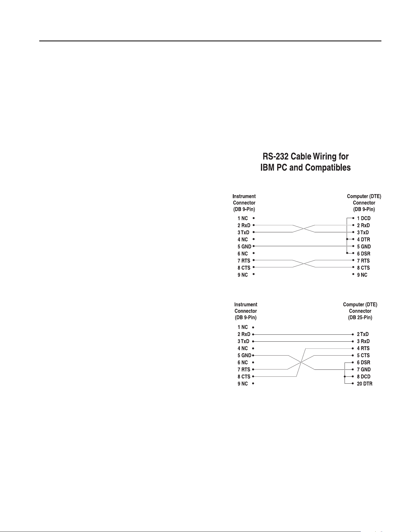
45
Digital Communication Interface
Serial Communications
10 Digital Communication Interface
The Micro-Bath calibrator is capable of communicating with and being con trolled by
other equipment through the digital serial interface.
With a digital interface the instrument may be connected to a computer or other
equipment. This allows the user to set the set-point temperature, monitor the
temperature, and access any of the other controller functions, all using remote
communications equipment. Communications commands are summarized in Table 5
on page 48.
Serial Communications 10.1
The calibrator is installed with an
RS-232 serial interface that allows
serial dig ital communications over
fairly long distances. With the serial
interface the user may access any of
the functions, parameters and settings
discussed in Section 9 with the
exception of the BAUD rate setting.
Wiring 10.1.1
The serial communications cable
attaches to the calibrator through the
DB-9 connector at the back of the
instrument. Figure 8 shows the pin-
out of this connector and sug gested
cable wiring. To eliminate noise the
serial cable should be shielded with
low resistance be tween the connector
(DB-9) and the shield. If the unit is
used in a heavy industrial setting, the
serial cable must be limited to ONE
METER in length.
Setup 10.1.2
Before operation the serial inter face
must first be set up by pro gramming the
BAUD rate and other configuration parameters. These parameters are programmed
within the serial interface menu. The serial interface parameters menu is outlined in
Figure 7 on page 32.
To enter the serial parameter pro gramming mode first press “EXIT” while pressing
“SET” and release to enter the secondary menu. Press “SET” re peatedly until
the display reads “PAr”. Press “UP” until the serial interface menu is indicated
with“SErIAL”. Finally press “SET” to enter the serial pa rameter menu. In the serial
Serial Cable Wiring Figure 8
1.888.610.7664 sales@GlobalTestSupply.com
Fluke-Direct.com

6102 Micro-Bath User’s Guide
Serial Communications
46
interface parameters menu are the BAUD rate, the sample rate, the duplex mode, and
the linefeed parameter.
Baud Rate 10.1.2.1
The baud rate is the first parameter in the menu. The display will prompt with the
baud rate parameter by showing “bAUd”. Press “SET” to choose to set the baud rate.
The current baud rate value will then be displayed. The baud rate of the 6102 serial
communications may be programmed to 300, 600, 1200, 2400, 4800, or 9600 baud.
The baud rate is pre-programmed to 2400 baud. Use “UP” or “DOWN” to change the
baud rate value. Press “SET” to set the baud rate to the new value or “EXIT” to abort
the operation and skip to the next pa rameter in the menu.
Sample Period10.1.2.2
The sample period is the next parameter in the menu and prompted with “SPEr”.
The sample period is the time period in seconds between temperature measurements
transmitted from the serial interface. If the sample rate is set to 5, the instrument
transmits the current measurement over the serial interface ap proximately every five
seconds. The automatic sampling is disabled with a sample period of 0. Press “SET”
to choose to set the sample period. Adjust the period with “UP” or “DOWN” and then
use “SET” to set the sample rate to the displayed value.
Duplex Mode10.1.2.3
The next parameter is the duplex mode indicated with “dUPL”. The duplex mode
may be set to half duplex (“HALF”) or full duplex (“FULL”). With full duplex any
commands received by the thermometer via the serial interface will be immediately
echoed or transmitted back to the device of origin. With half duplex the commands
will be executed but not echoed. The default setting is full duplex. The mode may be
changed using “UP” or “DOWN” and pressing “SET”.
Linefeed10.1.2.4
The final parameter in the serial interface menu is the linefeed mode. This pa rameter
enables (“On”) or disables (“OFF”) transmission of a linefeed charac ter (LF, ASCII
10) after transmission of any carriage-return. The default setting is with linefeed on.
The mode may be changed using “UP” or “DOWN” and pressing “SET”.
Serial Operation10.1.3
Once the cable has been attached and the interface set up properly the control ler will
immediately begin transmitting temperature readings at the pro grammed rate. The
serial communications uses 8 data bits, one stop bit, and no parity. The set-point and
other commands may be sent via the serial interface to set the temperature set-point
and view or program the various parameters. The interface commands are discussed
in Section 10.2. All commands are ASCII character strings terminated with a carriage-
return character (CR, ASCII 13).
1.888.610.7664 sales@GlobalTestSupply.com
Fluke-Direct.com

47
Digital Communication Interface
Interface Commands
10.2 Interface Commands
The various commands for accessing the calibrator functions via the digital in terfaces
are listed in this section (see Table 5). These commands are used with the RS-232
serial interface. The commands are terminated with a carriage-re turn character. The
interface makes no distinction between upper and lower case letters, hence either may
be used. Commands may be abbreviated to the minimum number of letters which
determines a unique command. A command may be used to either set a parameter or
display a parameter depending on whether or not a value is sent with the command
following a “=” character. For example “s”<CR> will return the current set-point and
“s=150.0”<CR> will set the set-point to 150.0 degrees.
In the following list of commands, characters or data within brackets, “[” and “]”, are
optional for the command. A slash, “/”, denotes alternate characters or data. Numeric
data, denoted by “n”, may be entered in decimal or exponential notation. Characters
are shown in lower case although upper case may be used. Spaces may be added
within command strings and will simply be ignored. Backspace (BS, ASCII 8) may be
used to erase the previous character. A termi nating CR is implied with all commands.
1.888.610.7664 sales@GlobalTestSupply.com
Fluke-Direct.com

6102 Micro-Bath User’s Guide
Interface Commands
48
Table 5 Controller Communications Commands
Command Description Command Format Command Example Returned Returned Example Acceptable Values
Display Temperature
Read current set-point s[etpoint] s set: 999.99 {C or F} set: 150.00 C
Set current set-point to n s[etpoint]=n s=200.00 Instrument Range
Read temperature t[emperature] t t: 999.99 {C or F} t: 55.6 C
Read temperature units u[nits] u u: x u: C
Set temperature units: u[nits]=c/f C or F
Set temperature units to Celsius u[nits]=c u=c
Set temperature units to
Fahrenheit
u[nits]=f u=f
Read scan mode sc[an] sc scan: {ON or OFF} scan:ON
Set scan mode sc[an]=on/off sc=on ON or OFF
Read scan rate sr[ate] sr srat: 99.9 {C or F}/min srat:12.4C/min
Set scan rate sr[ate]=n sr=1.1 .1 to 99.9
Read hold ho[ld] ho hold: open/closed,
99.9 {C or F}
hold: open, 30.5 C
Secondary Menu
Read proportional band setting pr[opband] pr pb: 999.9 pb: 15.9
Set proportional band to n pr[opband]=n pr=8.83 Depends on
Conguration
Read heater power
(duty cycle)
po[wer] po po: 999.9 po: 1.0
Conguration Menu
Operating Parameters Menu
Read stirrer motor speed mo[tor] mo mo: 99 mo: 15
Set stirrer motor speed to n mo[tor]=n mo=16 0 to 40
Serial Interface Menu
Read serial sample setting sa[mple] sa sa: 9 sa: 1
Set serial sampling setting to n
seconds
sa[mple]=n sa=0 0 to 999
Set serial duplex mode: du[plex]=f[ull]/h[alf] FULL or HALF
Set serial duplex mode to full du[plex]=f[ull] du=f
Set serial duplex mode to half du[plex]=h[alf] du=h
Set serial linefeed mode: lf[eed]=on/of[f] ON or OFF
Set serial linefeed mode to on lf[eed]=on lf=on
Set serial linefeed mode to off lf[eed]=of[f] lf=of
Calibration Menu
Read R0 calibration parameter r[0] r r0: 999.999 r0: 100.578
Set R0 calibration parameter to n r[0]=n r=100.324 90 to 110
Read ALPHA calibration
parameter
al[pha] al al: 9.9999999 al: 0.0038573
Set ALPHA calibration parameter
to n
al[pha]=n al=0.0038433 .002 to .005
Read DELTA calibration
parameter
de[lta] de de:9.99999 de: 1.507
Set DELTA calibration parameter de[lta]=n de=1.3742 0–3.0
Read C0 calibration parameter *c[0] *c c0:99.9999 c0:-0.297
Set C0 calibration parameter *c[0]=n *c=-5.113
Read CG calibration parameter *cg *cg cg:99.999 cg:-0.555
Set CG calibration parameter *cg=n *cg=-4.115
Functions not on menu
Read rmware version number *ver[sion] *ver ver.9999,9.99 ver.6102,2.00
Read structure of all commands h[elp] h list of commands
Read all operating parameters all all list of parameters
Legend: [] Optional Command data
{} Returns either information
n Numeric data supplied by user
9 Numeric data returned to user
x Character data returned to user
Note: When DUPLEX is set to FULL and a command is sent to READ, the command is returned followed by a carriage return and
linefeed. Then the value is returned as indicated in the RETURNED column.
1.888.610.7664 sales@GlobalTestSupply.com
Fluke-Direct.com

49
Test Probe Calibration
Calibrating a Single Probe
Test Probe Calibration11
Note: This procedure is to be considered a general guideline. Each laboratory
should write their own procedure based on their equipment and their quality
program. Each procedure should be accompanied by an uncertainty analysis
also based on the laboratory’s equipment and environment.
For optimum accuracy and stability, allow the calibrator to warm up for 25 minutes
after power-up and then allow adequate stabilization time after reach ing the set-point
temperature. After completing operation of the calibrator, al low the well to cool by
setting the temperature to 25°C for one-half hour before switching the power off.
Calibrating a Single Probe 11.1
Insert the probe to be calibrated into the well of the bath. Best results are ob tained
with the probe inserted to the full depth of the well. Once the probe is in serted into
the well, allow adequate stabilization time to allow the test probe temperature to settle
as described above. Once the probe has settled to the tem perature of the well, it may
be compared to the calibrator display temperature. The display temperature should be
stable to within 0.1°C degree for best results.
Caution: Never introduce any foreign material into the well.
Stabilization and Accuracy 11.2
The stabilization time of the Micro-Bath depends on the conditions and temper atures
involved. Typically the test well will be stable to 0.1°C within 10 min utes of reaching
the set-point temperature. Ultimate stability will be achieved 30 minutes after reaching
the set temperature.
Inserting a cold probe into a well requires another period of stabilizing depend ing on
the magnitude of the disturbance and the required accuracy. For exam ple, inserting a
.25 inch diameter room temperature probe at 200°C takes 5 minutes to be within 0.1°C
of its settled point and takes 10 minutes to achieve maximum stability.
Speeding up the calibration process can be accomplished by knowing how soon
to make the measurement. Typical measurements should be made at the desired
temperatures with the desired test probes to establish these times.
Multiple Probe Calibration 11.3
When calibrating multiple probes, place the probes equally spaced around the inside
edge of the probe basket.
1.888.610.7664 sales@GlobalTestSupply.com
Fluke-Direct.com

1.888.610.7664 sales@GlobalTestSupply.com
Fluke-Direct.com

51
Calibration Procedure
Calibration Points
12 Calibration Procedure
Note: This procedure is to be considered a general guideline. Each laboratory
should write their own procedure based on their equipment and their quality
program. Each procedure should be accompanied by an uncertainty analysis
also based on the laboratory’s equipment and environment.
Sometimes the user may want to calibrate the bath to improve the temperature
set-point accuracy. Calibration is done by adjusting the controller probe calibra tion
constants R0, ALPHA, and DELTA so that the temperature of the bath as measured
with a standard thermometer agrees more closely with the set-point. The thermometer
used must be able to measure the well temperature with higher accuracy than the
desired accuracy of the bath. By using a good thermometer and following this
procedure the bath can be calibrated to an ac curacy of better than 0.5°C up to 200°C.
Calibration Points 12.1
In calibrating the bath, R0, ALPHA, and DELTA are adjusted to mini mize the set-
point error at each of three different bath temperatures. Any three reasonably separated
temperatures may be used for the calibration. Improved results can be obtained for
shorter ranges when using temperatures that are just within the most useful operating
range of the Micro-Bath. The farther apart the calibration temperatures, the larger
will be the calibrated temperature range but the calibration error will also be greater
over the range. If for instance 50°C to 150°C is chosen as the calibration range then
the calibrator may achieve an ac curacy of say ±0.3°C over the range 50 to 150°C.
Choosing a range of 50°C to 90°C may allow the calibrator to have a better accuracy
of maybe ±0.2°C over that range but outside that range the accuracy may be only
±1.5°C.
Calibration Procedure 12.2
Choose three set-points to use in the calibration of the R0, ALPHA, and DELTA 1.
parameters. These set-points are generally 40°C, 95°C, and 195°C but other set-
points may be used if desired or necessary.
Set the bath to the low set-point. When the bath reaches the set-point and the 2.
display is stable, wait 15 minutes or so and then take a reading from the ther-
mometer. Sample the set-point resistance by holding down the “SET” key and
pressing the “DOWN” key. Write these values down as T
1
and R
1
respectively.
Repeat step 2 for the other two set-points recording them as T3.
2
, R
2
, T
3
, and R
3
respectively.
Using the recorded data, calculate new values for R0, ALPHA, and DELTA 4.
parameters using the equations given below:
1.888.610.7664 sales@GlobalTestSupply.com
Fluke-Direct.com

6102 Micro-Bath User’s Guide
Calibration Procedure
52
Compute DELTA 12.2.1
AT T
32
BT T
21
C
TT
TT
§
©
¨
¶
¸
·
§
©
¨
¶
¸
·
§
©
¨
¶
¸
·
§
©
¨
¶
¸
·
33
22
100
1
100 100
1
100
D
TTTT
§
©
¨
¶
¸
·
§
©
¨
¶
¸
·
§
©
¨
¶
¸
·
§
©
¨
¶
¸
·
2211
100
1
100 100
1
100
ERT
32
FRT
21
delta
AF BE
DE CF
T
1-3
– Measured temperature using thermometer.
R
1-3
– Value of R from display of 6102 (Press SET and DOWN at the same time.)
where
T
1
and R
1
are the measured temperature and resistance at 50.0 °C
T
2
and R
2
are the measured temperature and resistance at 90.0 °C
T
3
and R
3
are the measured temperature and resistance at 150.0 °C
Compute R0 & ALPHA12.2.2
a T delta
TT
11
11
100
1
100
§
©
¨
¶
¸
·
§
©
¨
¶
¸
·
a T delta
TT
33
33
100
1
100
§
©
¨
¶
¸
·
§
©
¨
¶
¸
·
rzero
Ra Ra
aa
31 13
13
alpha
RR
Ra Ra
13
31 13
Where:
delta is the new value of DELTA computed above
Program the new values for DELTA (delta), R0 (rzero), and ALPHA (alpha) into the
Micro-Bath with the following steps.
Press “SET” and “EXIT” keys at the same time and then press “SET” until 1.
1.888.610.7664 sales@GlobalTestSupply.com
Fluke-Direct.com

53
Calibration Procedure
Calibration Procedure
“R0” is displayed.
Press “SET” then use the “UP” or “DOWN” keys until the correct nu merical 2.
setting is displayed. Press “SET” to accept the new value.
Repeat step 2 for ALPHA and DELTA. 3.
Accuracy & Repeatability 12.2.3
Check the accuracy of the Micro-Bath at various points over the calibrated range.
If Micro-Bath does not pass specification at all set-points, repeat the Calibration
Procedure.
1.888.610.7664 sales@GlobalTestSupply.com
Fluke-Direct.com

1.888.610.7664 sales@GlobalTestSupply.com
Fluke-Direct.com

55
Maintenance
13 Maintenance
The calibration instrument has been designed with the utmost care. Ease of
L
operation and simplicity of maintenance have been a central theme in the
product development. Therefore, with proper care the instrument should require
very little maintenance. Avoid operating the instrument in an oily, wet, dirty, or
dusty environment.
If the outside of the instrument becomes soiled, it may be wiped clean with
L
a damp cloth and mild detergent. Do not use harsh chemicals on the surface
which may damage the paint.
It is important to keep the well of the calibrator clean and clear of any for eign
L
matter. DO NOT use chemicals to clean the well.
The bath should be handled with care. Avoid knocking or dropping the
L
instrument.
If a hazardous material is spilt on or inside the equipment, the user is
L
responsible for taking the appropriate decontamination steps as outlined by the
national safety council with respect to the material.
If the mains supply cord becomes damaged, replace it with a cord with the
L
appropriate gauge wire for the current of the instrument. If there are any
questions, call an Authorized Service Center for more information.
Before using any cleaning or decontamination method except those
L
recommended by Hart, users should check with an Authorized Service Center to
be sure that the proposed method will not damage the equipment.
If the instrument is used in a manner not in accordance with the equip ment
L
design, the operation of the Micro-Bath may be impaired or safety hazards may
arise.
1.888.610.7664 sales@GlobalTestSupply.com
Fluke-Direct.com

1.888.610.7664 sales@GlobalTestSupply.com
Fluke-Direct.com

57
Troubleshooting
Troubleshooting Problems, Possible Causes, and Solutions
Troubleshooting14
This section contains information on troubleshooting and CE Comments.
Troubleshooting Problems, Possible Causes, and Solutions 14.1
In the event that the instrument appears to function abnormally, this section may help
to find and solve the problem. Several possible problem conditions are described along
with likely causes and solutions. If a problem arises, please read this section carefully
and attempt to understand and solve the problem. If the problem cannot otherwise be
solved, contact an Authorized Service Center (see Section 1.3). Be sure to have the
model number and serial number of your instrument available.
Problem Possible Causes and Solutions
Incorrect tempera ture
reading
Incorrect R0, ALPHA, and DELTA parameters. Find the value for R0, ALPHA, and
DELTA on the Report of Calibration that was shipped with the instrument. Reprogram
the parameters into the instrument (see Section 9.12, Calibration Parameters). Allow the
instrument to stabilize and verify the accuracy of the temperature reading.
Controller locked up. The controller may have locked up due to a power surge or other
aberration. Initialize the system by performing the Factory Reset Sequence.
Factory Reset Sequence. Hold the SET and EXIT buttons down at the same time while
powering up the instrument. The instrument displays shows ‘ -init-’, the model number,
and the rmware version. Each of the controller parameters and cali bration constants
must be reprogrammed. The values can be found on the Report of Calibration that was
shipped with the instrument.
Instrument does not
heat or heats at half
rate
Power switch may be set incorrectly. Make sure the 115/230 VAC switch and the PEM
and heater switch are set to the correct type of input voltage. Check that the fuse is not
blown. If the fuse is blown, the display should be out.
The instrument heats
or cools too quickly or
too slowly
Incorrect scan and scan rate settings. The scan and scan rate settings may be set to
unwanted values. Check the Scan and Scan Rate settings. The scan may be off (if the
unit seems to be responding too quickly). The scan may be on with the Scan Rate set low
(if unit seems to be responding too slowly).
An “o” is displayed at
the left of the display
External switch is open. The external switch is open causing the displayed temperature
to be frozen and keeping the set-point from scanning. Turn the switch test off by pressing
the “DOWN” button on the front panel.
The display shows
any error of the
following:
Err 1, Err 2,
Err 3, Err 4 or
Err 5
Controller problem. The error messages signify the following problems with the
controller.
Err 1 – a RAM error
Err 2 – a NVRAM error
Err 3 – a Structure error
Err 4 – an ADC setup error
Err 5 – an ADC ready error
Initialize the system by performing the Factory Reset Sequence described above.
The display shows
Err 6
Defective control sensor. The control sensor may be shorted, open or otherwise
damaged.
The display shows
Err 7
Heater control error. Initialize the system by performing the Factory Reset Sequence
described above.
The stirrer is not
stirring
Stirrer speed needs adjusting. In the Operating Parameters menu, adjust the stirrer
speed (“Str Sp”) to 0. Wait for the motor to stop. Adjust the stirrer speed to a setting
greater than 8 but less than or equal to 25.
Temperature readout
is not the actual
temperature of the
well
Possible RF energy emission. With the unit stable, slowly rotate the unit. If no change
occurs, the unit may need to be calibrated. If the display changes more than twice the
normal display deviation, another unit in the area could be emitting RF en ergy. Move the
unit to a different location and rotate the unit again. If the temperature is correct in this
new area or deviates differently than the rst are, RF energy is pres ent in the room. If you
have to perform the test in the effected area, use the compari son test to eliminate any
possible errors.
Instrument is unstable Varying line voltage or uid is not stirring. Place the unit on a clean power line. If the
uid is not stirring, turn the instrument off for one minute.
1.888.610.7664 sales@GlobalTestSupply.com
Fluke-Direct.com

6102 Micro-Bath User’s Guide
CE Comments
58
Problem Possible Causes and Solutions
AC voltage present on
the chassis
Use a wall plug tester to check the main power plug at the wall. Use an ohmmeter to
check the continuity between the ground prong on the PEM and the chassis. If the
resistance reading is greater than three ohms, there is a problem. Check the power cord
for continuity on the ground prongs. If the resistance is greater than one ohm, re place the
power cord.
Power Up The instrument is equipped with operator accessible fuses. If a fuse blows, it may be due
to a power surge or failure of a component. Replace the fuse once. If the fuse blows a
second time, it is likely caused by failure of a component part. If this occurs, contact an
Authorized Service Center. Always replace the fuse with one of the same rating, voltage,
and type. Never replace the fuse with one of a higher current rating.
CE Comments14.2
EMC Directive14.2.1
Hart Scientifics’ equipment has been tested to meet the European Electromagnetic
Compatibility Directive (EMC Directive, 89/336/EEC). The Declaration of
Conformity for your instrument lists the specific standards to which the unit was
tested.
For units used in the “field”, a slight degradation of accuracy may be noticed between
300-350 MHz with a field intensity of 10V/M at the unit. A piece of equipment in
proximity to the unit under test must emit greater than 1000 times the permissible CE
standard (EN55022) at these specific frequencies to have any effect on the unit. Units
used in a laboratory are not affected.
Low Voltage Directive (Safety)14.2.2
In order to comply with the European Low Voltage Directive (73/23/EEC), Hart
Scientific equipment has been designed to meet the EN 61010-1 and EN 61010-2-010
standards.
1.888.610.7664 sales@GlobalTestSupply.com
Fluke-Direct.com