
Revision 7A1901-EN
914X Series
Field Metrology Well
User’s Guide
1.888.610.7664 sales@GlobalTestSupply.com
Fluke-Direct.com

ii
Limited Warranty & Limitation of Liability
Each product from Fluke Corporation, Hart Scientic Division (“Hart”) is warranted to be free from defects in material
and workmanship under normal use and service. The warranty period is one year for Field Metrology Wells. The war-
ranty period begins on the date of the shipment. Parts, product repairs, and services are warranted for 90 days. The war-
ranty extends only to the original buyer or end-user customer of a Hart authorized reseller, and does not apply to fuses,
disposable batteries or to any other product, which in Hart’s opinion, has been misused, altered, neglected, or damaged
by accident or abnormal conditions of operation or handling. Hart warrants that software will operate substantially in
accordance with its functional specications for 90 days and that it has been properly recorded on non-defective media.
Hart does not warrant that software will be error free or operate without interruption. Hart does not warrant calibrations
on the Field Metrology Well.
Hart authorized resellers shall extend this warranty on new and unused products to end-user customers only but have
no authority to extend a greater or different warranty on behalf of Hart. Warranty support is available if product is
purchased through a Hart authorized sales outlet or Buyer has paid the applicable international price. Hart reserves
the right to invoice Buyer for importation costs of repairs/replacement parts when product purchased in one country is
submitted for repair in another country.
Hart’s warranty obligation is limited, at Hart’s option, to refund of the purchase price, free of charge repair, or replace-
ment of a defective product which is returned to a Hart authorized service center within the warranty period.
To obtain warranty service, contact your nearest Hart authorized service center or send the product, with a description
of the difculty, postage, and insurance prepaid (FOB Destination), to the nearest Hart authorized service center. Hart
assumes no risk for damage in transit. Following warranty repair, the product will be returned to Buyer, transportation
prepaid (FOB Destination). If Hart determines that the failure was caused by misuse, alteration, accident or abnormal
condition or operation or handling, Hart will provide an estimate or repair costs and obtain authorization before com-
mencing the work. Following repair, the product will be returned to the Buyer transportation prepaid and the Buyer will
be billed for the repair and return transportation charges (FOB Shipping Point).
THIS WARRANTY IS BUYER’S SOLE AND EXCLUSIVE REMEDY AND IS IN LIEU OF ALL OTHER WAR-
RANTIES, EXPRESS OR IMPLIED, INCLUDING BUT NOT LIMITED TO ANY IMPLIED WARRANTY OF
MERCHANTABILITY OR FITNESS FOR A PARTICULAR PURPOSE. HART SHALL NOT BE LIABLE FOR
ANY SPECIAL, INDIRECT, INCIDENTAL. OR CONSEQUENTIAL DAMAGES OR LOSSES, INCLUDING LOSS
OF DATA, WHETHER ARISING FROM BREACH OF WARRANTY OR BASED ON CONTRACT, TORT, RELI-
ANCE OR ANY OTHER THEORY.
Since some countries or states do not allow limitation of the term of an implied warranty, or exclusion or limitation of
incidental or consequential damages, the limitations and exclusions of this warranty may not apply to every buyer. If
any provision of this Warranty is held invalid or unenforceable by a court of competent jurisdiction, such holding will
not affect the validity or enforceability of any other provision.
Specifications subject to change without notice. • Copyright © 2007 • Printed in USA
1.888.610.7664 sales@GlobalTestSupply.com
Fluke-Direct.com

iii
Table of Contents
1 Before You Start .......................................................................1
1.1 Introduction ............................................................................................... 1
1.2 Unpacking ................................................................................................ 2
1.3 Symbols Used ........................................................................................... 3
1.4 Safety Information ..................................................................................... 4
1.4.1 Warnings .........................................................................................................5
1.4.2 Cautions ..........................................................................................................7
1.5 CE Comments ........................................................................................... 8
1.5.1 EMC Directive .................................................................................................8
1.5.2 Immunity Testing .............................................................................................8
1.5.3 Emission Testing ..............................................................................................9
1.5.4 Low Voltage Directive (Safety) ........................................................................9
1.6 Authorized Service Centers ...................................................................... 9
2 Specications and Environmental Conditions ....................13
2.1 Specifications ......................................................................................... 13
2.2 Environmental Conditions ....................................................................... 15
3 Quick Start ..............................................................................17
3.1 Setup ....................................................................................................... 17
3.2 Parts and Controls .................................................................................. 18
3.2.1 Display Panel ................................................................................................19
3.2.2 Display ..........................................................................................................20
3.2.3 Power Panel ..................................................................................................22
3.2.4 -P Option Panel (-P models only) ..................................................................24
3.3 Languages .............................................................................................. 26
3.3.1 Language Selection ......................................................................................26
3.3.2 Reset to English Language ...........................................................................27
4 Menu Structure .......................................................................29
4.1 Temp Setup Menu ................................................................................... 29
4.2 Prog Menu .............................................................................................. 30
4.2.1 Switch Test Parameters .................................................................................31
4.2.2 Switch Test Description .................................................................................31
4.3 System Menu .......................................................................................... 33
4.4 Input Setup (-P only) ............................................................................... 34
1.888.610.7664 sales@GlobalTestSupply.com
Fluke-Direct.com

iv
5 Maintenance ...........................................................................35
5.1 Field Metrology Well Performance Analysis ........................................... 35
1.888.610.7664 sales@GlobalTestSupply.com
Fluke-Direct.com

v
Tables
Table 1 Symbols used ........................................................................................ 3
Table 2 Base Unit Specifications ..................................................................... 13
Table 3 -P Option Specifications ..................................................................... 14
1.888.610.7664 sales@GlobalTestSupply.com
Fluke-Direct.com

vi
Figures
Figure 1 Clamp-on ferrite installation ................................................................. 9
Figure 2 914X Field Metrology Well ................................................................. 18
Figure 3 Display panel and keys .................................................................... 20
Figure 4 914X display ...................................................................................... 21
Figure 5 9142 power panel .............................................................................. 23
Figure 6 9143 and 9144 power panel .............................................................. 23
Figure 7 -P option panel ................................................................................. 24
Figure 8 Probe connector wiring ..................................................................... 25
Figure 9 Jumper locations for 3-wire and 2-wire connections ......................... 26
Figure 10 Steps to language selection ............................................................ 27
Figure 11 Main Menu - Temp SetUp ................................................................ 29
Figure 12 Main Menu - Prog Menu .................................................................. 30
Figure 13 Auto and manual switch test operation example ............................ 32
Figure 14 Main Menu - System Menu .............................................................. 33
Figure 15 Main Menu - Input Setup ................................................................ 34
1.888.610.7664 sales@GlobalTestSupply.com
Fluke-Direct.com

1
Before You Start
Introduction
Before You Start1
Introduction1.1
Field Metrology Wells (9142, 9143, and 9144) are designed to be reliable, stable heat sources
that can be used in the eld or laboratory. They offer accuracy, portability, and speed for nearly
every eld calibration application. The instruments have been designed with the eld user in
mind and are easy to use while maintaining stability, uniformity, and accuracy comparable to
some laboratory instruments.
Special built-in features make Field Metrology Wells extremely adaptable. The exclusive Volt-
age Compensation allows the technician to plug into mains power with voltage from 90 V ac to
250 V ac without degradation to the instrument. The Ambient Temperature Compensation (Pat-
ent Pending) provides the largest operating range in the industry (0°C to 50°C) with the largest
guaranteed temperature range (13°C to 33°C). The Gradient Temperature Compensation (Pat-
ent Pending) keeps the axial gradient within specication over the entire temperature range of
the instrument and over the specied guaranteed operating temperature range. These combined
features along with the rugged design, light weight, and small size make this line of instruments
ideal for eld applications.
Unique Patent Pending safety features make these the safest eld heat sources available. The
unique Air Flow Design (Patent Pending) keeps the probe handle cool protecting delicate in-
struments and the user. The Block Temperature Indicator (Patent Pending) shows the user when
the well temperature is above 50°C letting the user know when it is safe to remove the insert or
move the instrument. The indicator light illuminates when the instrument is energized and the
well is above 50°C. If the instrument is removed from mains power, the indicator light ashes
until the well has cooled to less than 50°C.
The optional “Process” version (“914X–P”) combines the heat source with a built-in readout
eliminating the need for the technician to take two instruments to the eld. The readout is per-
fect for transmitter loop, comparison calibration, or a simple check of a thermocouple sensor.
There is no need to carry additional tools into the eld with the “Process” option of a built-in
readout for resistance, voltage, and mA measurement, 24V loop power, and on-board documen-
tation. The convenient smart reference connector automatically transfers and stores the probe
coefcients.
The Field Metrology Wells’ controller uses a PRT sensor and thermoelectric modules or heaters
to achieve stable, uniform temperatures throughout the block.
The LCD display continuously shows many useful operating parameters including the block
temperature, the current set-point, block stability, and heating and cooling status. For the Pro-
cess version, the reference temperature and secondary input type (UUT) readings are displayed.
The display can be set to show the information in one of eight different languages; English,
Japanese, Chinese, German, Spanish, French, Russian, and Italian.
The instrument’s rugged design and special features make them ideal for the eld or the labora-
tory. With proper use, the instrument provides continued accurate calibration of temperature
1.888.610.7664 sales@GlobalTestSupply.com
Fluke-Direct.com

914X Field Metrology Wells
Unpacking
2
sensors and devices. Before use, the user should be familiar with the warnings, cautions, and
operating procedures of the calibrator as described in the User’s Guide.
Unpacking1.2
Unpack the instrument carefully and inspect it for any damage that may have occurred during
shipment. If there is shipping damage, notify the carrier immediately.
Verify that the following components are present:
9142
9142 Field Metrology Well
●●
9142-INSX Insert (X=A, B, C, D, E, or F)
●●
Power Cord
●●
RS-232 Cable
●●
User Guide
●●
Technical Manual CD
●●
Report of Calibration and calibration label
●●
6-pin DIN Connector (-P model only)
●●
Test Lead Kit (-P model only)
●●
Well Insulator
●●
Clamp-on ferrites (3) [-P model only]
●●
Tongs (insert removal tool)
●●
9930 Interface-it Software and User’s Guide
●●
9143
9143 Field Metrology Well
●●
9143-INSX Insert (X=A, B, C, D, E, or F)
●●
Power Cord
●●
RS-232 Cable
●●
User Guide
●●
Technical Manual CD
●●
Report of Calibration and calibration label
●●
6-pin DIN Connector (-P model only)
●●
Test Lead Kit (-P model only)
●●
Clamp-on ferrites (3) [-P model only]
●●
Tongs (insert removal tool)
●●
9930 Interface-it Software and User’s Guide
●●
1.888.610.7664 sales@GlobalTestSupply.com
Fluke-Direct.com
3
Before You Start
Symbols Used
9144
9144 Field Metrology Well
●●
9144-INSX Insert (X=A, B, C, D, E, or F)
●●
Power Cord
●●
RS-232 Cable
●●
User Guide
●●
Technical Manual CD
●●
Report of Calibration and calibration label
●●
6-pin DIN Connector (-P model only)
●●
Test Lead Kit (-P model only)
●●
Clamp-on ferrites (3) [-P model only]
●●
Tongs (insert removal tool)
●●
9930 Interface-it Software and User’s Guide
●●
If all items are not present, contact an Authorized Service Center (see Section 1.6 Authorized
Service Centers on page 9).
Symbols Used1.3
Table 1 lists the International Electrical Symbols. Some or all of these symbols may be used on
the instrument or in this guide.
Symbols usedTable 1
Symbol Description
AC (Alternating Current)
AC-DC
Battery
Complies with European Union directives
DC
Double Insulated
1.888.610.7664 sales@GlobalTestSupply.com
Fluke-Direct.com
914X Field Metrology Wells
Safety Information
4
Symbol Description
Electric Shock
Fuse
PE Ground
Hot Surface (Burn Hazard)
Read the User’s Guide (Important Information)
Off
On
Canadian Standards Association
C-TICK Australian EMC mark
The European Waste Electrical and Electronic Equipment (WEEE) Directive (2002/96/
EC) mark.
Safety Information1.4
Field Metrology Wells are designed in accordance with IEC 61010-1, IEC 61010-2-010 and
CAN/CSA 22.2 No 61010.1-04. Use this instrument only as specied in this manual. Other-
wise, the protection provided by the instrument may be impaired. Refer to the safety informa-
tion in the Warnings and Cautions sections below.
The following denitions apply to the terms “Warning” and “Caution”.
“Warning” identies conditions and actions that may pose hazards to the user.
●●
“Caution” identies conditions and actions that may damage the instrument being used.
●●
1.888.610.7664 sales@GlobalTestSupply.com
Fluke-Direct.com

5
Before You Start
Safety Information
Warnings1.4.1
To avoid personal injury, follow these guidelines.
GENERAL
DO NOT use this instrument in environments other than those listed in the User’s Guide.
Inspect the instrument for damage before each use. Inspect the case. Look for cracks or missing
plastic. DO NOT use the instrument if it appears damaged or operates abnormally.
Follow all safety guidelines listed in the User’s Guide.
Calibration equipment should only be used by trained personnel.
If this equipment is used in a manner not specied by the manufacturer, the protection provided
by the equipment may be impaired.
Before initial use, or after transport, or after storage in humid or semi-humid environments,
or anytime the instrument has not been energized for more than 10 days, the instrument needs
to be energized for a “dry-out” period of 2 hours before it can be assumed to meet all of the
safety requirements of the IEC 1010-2. If the product is wet or has been in a wet environment,
take necessary measures to remove moisture prior to applying power such as storage in a low
humidity temperature chamber operating at 50°C for 4 hours or more.
DO NOT use this instrument for any application other than calibration work. The instrument
was designed for temperature calibration. Any other use of the instrument may cause unknown
hazards to the user.
DO NOT place the instrument under a cabinet or other structure. Overhead clearance is
required. Always leave enough clearance to allow for safe and easy insertion and removal of
probes.
Use of this instrument at HIGH TEMPERATURES for extended periods of time requires
caution.
Completely unattended high temperature operation is not recommended due to safety hazards
that can arise.
This instrument is intended for indoor use only.
Follow all safety procedures for the test and calibration equipment you use.
If used, inspect the test leads for damaged insulation or exposed metal. Check for test lead
continuity. Replace damaged test leads as necessary.
Do not use the instrument if it operates abnormally. Protection may be impaired. When in
doubt, have the instrument serviced.
Do not apply more than the rated voltage, as marked on the instrument, between terminals or
between any terminal and earth ground.
1.888.610.7664 sales@GlobalTestSupply.com
Fluke-Direct.com

914X Field Metrology Wells
Safety Information
6
Never touch the probes to a voltage source when the test leads are plugged into the current
terminals.
Select the proper function and range for each measurement.
Disconnect the test leads before changing to another measure or source function.
DO NOT operate the Field Metrology Well around explosive gas, vapor, or dust.
DO NOT operate instrument at orientations other than upright. Tilting the instrument or laying
it down on its side during use could create a re hazard.
BURN HAZARD
The instrument is equipped with a Block Temperature Indicator (front panel LED HOT indica-
tor – Patent Pending) even when the instrument is unplugged. When the indicator is ashing,
the instrument is disconnected from mains power and the temperature of the block is above
50°C. When the indicator is illuminated, always on, the instrument is powered and the block
temperature is above 50°C.
DO NOT turn the instrument upside down with the inserts in place; the inserts will fall out.
DO NOT operate near ammable materials.
Use of this instrument at HIGH TEMPERATURES for extended periods of time requires
caution.
DO NOT touch the well access surface of the instrument.
The block vent may be very hot due to the fan blowing across the heater block of the
instrument.
The temperature of the well access is the same as the actual display temperature, e.g. if the
instrument is set to 600°C and the display reads 600°C, the well is at 600°C.
Probes and inserts may be hot and should only be inserted and removed from the instrument
when the instrument indicates temperatures less than 50°C.
DO NOT turn off the instrument at temperatures higher than 100°C. This could create a
hazardous situation. Select a set-point less than 100°C and allow the instrument to cool before
turning it off.
The high temperatures present in Field Metrology Wells designed for operation at 300°C and
higher may result in res and severe burns if safety precautions are not observed.
ELECTRICAL HAZARD
These guidelines must be followed to ensure that the safety mechanisms in this instrument
operate properly. This instrument must be plugged into an AC only electric outlet according
to Table 2, Specications . The power cord of the instrument is equipped with a three-pronged
grounding plug for your protection against electrical shock hazards. It must be plugged directly
into a properly grounded three-prong receptacle. The receptacle must be installed in accordance
with local codes and ordinances. Consult a qualied electrician. DO NOT use an extension
cord or adapter plug.
1.888.610.7664 sales@GlobalTestSupply.com
Fluke-Direct.com

7
Before You Start
Safety Information
If supplied with user accessible fuses, always replace the fuse with one of the same rating, volt-
age, and type.
Always replace the power cord with an approved cord of the correct rating and type.
HIGH VOLTAGE is used in the operation of this equipment. SEVERE INJURY or DEATH
may result if personnel fail to observe safety precautions. Before working inside the equipment,
turn power off and disconnect power cord.
-P Model Only
When using test leads, keep ngers behind the nger guards on the test leads.
DO NOT apply more than the rated voltage, as marked on the instrument, between the termi-
nals, or between any terminal and earth ground (30 V 24 mA max all terminals).
Never touch the probe to a voltage source when the test leads are plugged into current
terminals.
Select the proper function and range for your measurement.
Inspect the test leads for damaged insulation or exposed metal. Check test leads continuity.
Replace damaged test leads before you use the calibrator.
Cautions1.4.2
To avoid possible damage to the instrument, follow these guidelines:
DO NOT leave the inserts in the instrument for prolonged periods. Due to the high operating
temperatures of the instrument, the inserts should be removed after each use and buffed with a
Scotch-Brite® pad or emery cloth (see Section 5 Maintenance on page 35).
Always operate this instrument at room temperature between 41°F and 122°F (5°C to 50°C).
Allow sufcient air circulation by leaving at least 6 inches (15 cm) of clearance around the
instrument. Overhead clearance of 1 meter (3 ft) is required. DO NOT place instrument under
any structure.
Component lifetime can be shortened by continuous high temperature operation.
DO NOT apply any type of voltage to the display hold terminals. Applying a voltage to the
terminals may cause damage to the controller.
DO NOT use uids to clean out the well. Fluids could leak into electronics and damage the
instrument.
Never introduce any foreign material into the probe hole of the insert. Fluids, etc. can leak into
the instrument causing damage.
Unless recalibrating the instrument DO NOT change the values of the calibration constants
from the factory set values. The correct setting of these parameters is important to the safety
and proper operation of the calibrator.
1.888.610.7664 sales@GlobalTestSupply.com
Fluke-Direct.com

914X Field Metrology Wells
CE Comments
8
DO NOT allow the probe sheath or inserts to drop into the well. This type of action can cause a
shock to the sensor and affect the calibration.
The instrument and any thermometer probes used with it are sensitive instruments that can be
easily damaged. Always handle these devices with care. DO NOT allow them to be dropped,
struck, stressed, or overheated.
DO NOT operate this instrument in an excessively wet, oily, dusty, or dirty environment. Al-
ways keep the well and inserts clean and clear of foreign material.
The Field Metrology Well is a precision instrument. Although it has been designed for optimum
durability and trouble free operation, it must be handled with care. Always carry the instrument
in an upright position to prevent the inserts from dropping out. The convenient handle allows
for hand carrying the instrument.
If a mains supply power uctuation occurs, immediately turn off the instrument. Power bumps
from brown-outs could damage the instrument. Wait until the power has stabilized before re-
energizing the instrument.
The probe and the block may expand at different rates. Allow for probe expansion inside the
well as the block heats. Otherwise, the probe may become stuck in the well.
Most probes have handle temperature limits. If the probe handle limits are exceeded, the probe
may be permanently damaged. Due to a unique Air Flow Design (Patent Pending), Field Me-
trology Wells protect the probe handle temperature and provide a safer temperature handle for
the user.
1.5 CE Comments
EMC Directive1.5.1
Hart Scientic’s equipment has been tested to meet the European Electromagnetic Compatibili-
ty Directive (EMC Directive, 89/336/EEC). The Declaration of Conformity for your instrument
lists the specic standards to which the instrument was tested.
The instrument was designed specically as a test and measuring device. Compliance to the
EMC directive is through IEC 61326-1 Electrical equipment for measurement, control and
laboratory use.
As noted in the IEC 61326-1, the instrument can have varying congurations. The instrument
was tested in a typical conguration with shielded RS-232 cables.
1.5.2 Immunity Testing
Using Clamp-On Ferrites
For the –P model only, clamp-on ferrites are provided for use in improving its electromagnetic
(EM) immunity in environments of excessive EM interference. During EMC testing we found
that ferrites clamped around probe cables for the Reference PRT, the PRT/RTD input, and the
thermocouple (TC) input reduced the risk the EM interference affects measurements. Therefore,
1.888.610.7664 sales@GlobalTestSupply.com
Fluke-Direct.com
9
Before You Start
Authorized Service Centers
we recommend that the clamp-on ferrites provided be used on the cables of probes attached
to the readout, especially if the product is used near sources of EM interference such as heavy
industrial equipment.
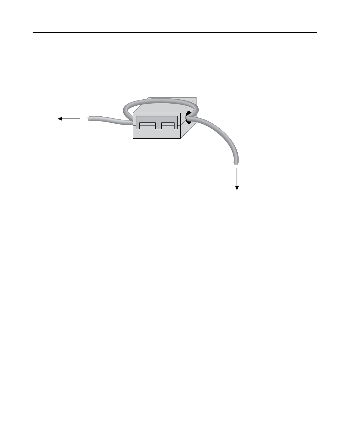
To attach a ferrite to a probe cable, make a loop in the cable near the connector and clamp the
ferrite around half of the loop as shown in the diagram. The ferrite can be easily snapped open
and moved to a new probe when needed.
clamp-on ferrite
connector
probe
Figure 1 Clamp-on ferrite installation
Emission Testing1.5.3
The instrument fullls the limit requirements for Class A equipment. The instrument was not
designed to be used in domestic establishments.
Low Voltage Directive (Safety)1.5.4
1.6
In order to comply with the European Low Voltage Directive (2006/95/EC), Hart Scientic
equipment has been designed to meet the EN 61010-1 and the EN 61010-2-010 standards.
Authorized Service Centers
Please contact one of the following Authorized Service Centers to coordinate service on your
Hart product:
1.888.610.7664 sales@GlobalTestSupply.com
Fluke-Direct.com

914X Field Metrology Wells
Authorized Service Centers
10
When contacting a Service Centers for support, please have the following information
available:
Model Number
●●
Serial Number
●●
Voltage
●●
Complete description of the problem
●●
1.888.610.7664 sales@GlobalTestSupply.com
Fluke-Direct.com

11
1.888.610.7664 sales@GlobalTestSupply.com
Fluke-Direct.com

1.888.610.7664 sales@GlobalTestSupply.com
Fluke-Direct.com
13
Specications and Environmental Conditions
Specications
Specications and Environmental Conditions2
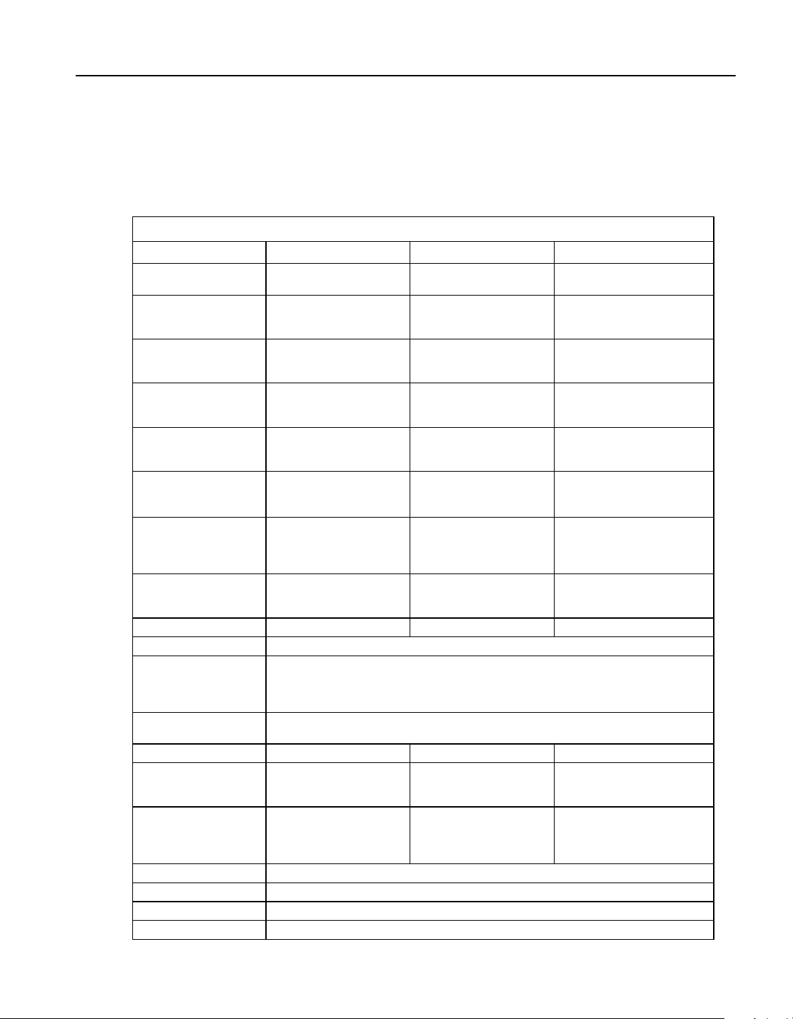
2.1 Specications
Table 2 Base Unit Specifications
Base Unit Specifications
9142 9143 9144
Temperature Range at
23 °C
–25 °C to 150 °C
(-13 °F to 302 °F)
33 °C to 350 °C
(91 °F to 662 °F)
50 °C to 660 °C
(122 °F to 1220 °F)
Display Accuracy ± 0.2 °C Full Range ± 0.2 °C Full Range ± 0.35 °C at 50 °C
± 0.35 °C at 420 °C
± 0.5 °C at 660 °C
Stability ± 0.01 °C Full Range ± 0.02 °C at 33 °C
± 0.02 °C at 200 °C
± 0.03 °C at 350 °C
± 0.03 °C at 50 °C
± 0.05 °C at 420 °C
± 0.05 °C at 660 °C
Axial Uniformity at 40
mm (1.6 in)
± 0.05 °C Full Range ± 0.04 °C at 33 °C
± 0.1 °C at 200 °C
± 0.2 °C at 350 °C
± 0.05 °C at 50 °C
± 0.35 °C at 420 °C
± 0.5 °C at 660 °C
Axial Uniformity at 60
mm (2.4 in)
± 0.07 °C Full Range ± 0.04 °C at 33 °C
± 0.2 °C at 200 °C
± 0.25 °C at 350 °C
± 0.1 °C at 50 °C
± 0.6 °C at 420 °C
± 0.8 °C at 660 °C
Radial Uniformity ± 0.01 °C Full Range ± 0.01 °C at 33 °C
± 0.015 °C at 200 °C
± 0.02 °C at 350 °C
± 0.02 °C at 50 °C
± 0.05 °C at 420 °C
± 0.1 °C at 660 °C
Loading Effect (with
a 6.35 mm reference
probe and three 6.35
mm probes)
± 0.006 °C Full Range ± 0.015 °C Full Range ± 0.015 °C at 50 °C
± 0.025 °C at 420 °C
± 0.035 °C at 660 °C
Loading Effect (versus
display with 6.35 mm
probes)
± 0.08 °C Full Range ± 0.2 °C Full Range ± 0.1 °C at 50 °C
± 0.2 °C at 420 °C
± 0.2 °C at 660 °C
Hysteresis 0.025 °C 0.03 °C 0.1 °C
Operating Conditions 0 °C to 50 °C, 0 % to 90 % RH (non-condensing)
Environmental
conditions for all
specications except
temperature range
13 °C to 33 °C
Immersion (Well)
Depth
150 mm (5.9 in)
Insert OD 30 mm (1.18 in) 25.3 mm (1.00 in) 24.4 mm (0.96 in)
Heating Time 16 min: 23 °C to 140 °C
23 min: 23 °C to 150 °C
25 min: –25 °C to 150 °C
5 min: 33 °C to 350 °C 15 min: 50 °C to 660 °C
Cooling Time 15 min: 23 °C to –25 °C
25 min: 150 °C to –23 °C
32 min: 350 °C to 33 °C
14 min: 350 °C to 100 °C
35 min: 660 °C to 50 °C
25 min: 660 °C to 100 °C
Resolution 0.01 °
Display LCD, °C or °F user-selectable
Key Pad Arrows, Menu, Enter, Exit, 4 soft keys
Size (H x W x D) 290 mm x 185 mm x 295 mm (11.4 x 7.3 x 11.6 in)
1.888.610.7664 sales@GlobalTestSupply.com
Fluke-Direct.com
914X Field Metrology Wells
Specications
14
Base Unit Specifications
9142 9143 9144
Weight 8.16 kg (18 lbs) 7.3 kg (16 lbs) 7.7 kg (17 lbs)
Power Requirements 100 V to 115 V (± 10 %)
50/60 Hz, 635 W
230 V (± 10 %) 50/60 Hz,
575 W
100 V to 115 V (± 10 %), 50/60 Hz, 1400 W
230 V (± 10%), 50/60 Hz, 1800 W
System Fuse Ratings 115 V: 6.3 A T 250 V
230 V: 3.15 A T 250 V
115 V: 15 A F 250 V
230 V: 10 A F 250 V
4–20 mA Fuse (-P
model only)
50 mA F 250V
Computer Interface RS-232 and 9930 Interface-it control software included
Safety EN 61010-1:2001, CAN/CSA C22.2 No. 61010.1-04
-P Option Specifications Table 3
-P Specifications
Built-in Reference Thermometer Readout
Accuracy
(4-Wire Reference Probe)
†
± 0.013 °C at -25 °C
± 0.015 °C at 0 °C
± 0.020 °C at 50 °C
± 0.025 °C at 150 °C
± 0.030 °C at 200 °C
± 0.040 °C at 350 °C
± 0.050 °C at 420 °C
± 0.070 °C at 660 °C
Reference Resistance Range 0 ohms to 400 ohms
Reference Resistance Accuracy‡ 0 ohms to 42 ohms: ±0.0025 ohms
42 ohms to 400 ohms: ±60 ppm of reading
Reference Characterizations ITS-90, CVD, IEC-751, Resistance
Reference Measurement Capability 4-wire
Reference Probe Connection 6 Pin Din with Infocon Technology
Built-in RTD Thermometer Readout Accuracy NI-120: ± 0.015 °C at 0 °C
PT-100 (385): ± 0.02 °C at 0 °C
PT-100 (3926): ± 0.02 °C at 0 °C
PT-100 (JIS): ± 0.02 °C at 0 °C
RTD Resistance Range 0 ohms to 400 ohms
Resistance Accuracy
‡
0 ohms to 25 ohms: ±0.002 ohms
25 ohms to 400 ohms: ±80 ppm of reading
RTD Characterizations PT-100 (385),(JIS),(3926), NI-120, Resistance
RTD Measurement Capability 2-,3-,4-wire RTD w\ Jumpers only
RTD Connection 4 terminal input
1.888.610.7664 sales@GlobalTestSupply.com
Fluke-Direct.com
15
Specications and Environmental Conditions
Environmental Conditions
-P Specifications
Built-in TC Thermometer Readout Accuracy Type J: ± 0.7 °C at 660 °C
Type K: ± 0.8 °C at 660 °C
Type T: ± 0.8 °C at 400 °C
Type E: ± 0.7 °C at 660 °C
Type R: ± 1.4 °C at 660 °C
Type S: ± 1.5 °C at 660 °C
Type M: ± 0.6 °C at 660 °C
Type L: ± 0.7 °C at 660 °C
Type U: ± 0.75 °C at 600 °C
Type N: ± 0.9 °C at 660 °C
Type C: ± 1.1 °C at 660 °C
TC Millivolt Range –10 mV to 75 mV
Voltage Accuracy 0.025 % of reading +0.01mV
Internal Cold Junction Compensation Accuracy ± 0.35 °C (ambient of 13 °C to 33 °C)
TC Connection Small connectors
Built-in mA Readout Accuracy 0.02% of reading + 0.002 mA
mA Range Cal 4-22 mA, Spec 4-24 mA
mA Connection 2 terminal input
Loop Power Function 24 VDC loop power
Built-in Electronics Temperature Coefficient
(0 °C to 13 °C, 33 °C to 50 °C)
± 0.005 % of range per °C
†
The temperature range may be limited by the reference probe connected to the readout. The Built-
In Reference Accuracy does not include the sensor probe accuracy. It does not include the probe
uncertainty or probe characterization errors.
‡
Measurement accuracy specications apply within the operating range and assume 4-wires for PRTs.
With 3-wire RTDs add 0.05 ohms to the measurement accuracy plus the maximum possible difference
between the resistances of the lead wires.
Environmental Conditions2.2
Although the instrument has been designed for optimum durability and trouble-free operation,
it must be handled with care. The instrument should not be operated in an excessively dusty or
dirty environment. Maintenance and cleaning recommendations can be found in the Mainte-
nance section. The instrument operates safely under the following environmental conditions:
ambient temperature range: 0-50°C (32-122°F)
●●
ambient relative humidity: 0 % to 90 % (non-condensing)
●●
mains voltage: within ±10% of nominal
●●
vibrations in the calibration environment should be minimized
●●
altitude: less than 2,000 meters
●●
indoor use only
●●
1.888.610.7664 sales@GlobalTestSupply.com
Fluke-Direct.com

1.888.610.7664 sales@GlobalTestSupply.com
Fluke-Direct.com

17
Quick Start
Setup
Quick Start3
Setup3.1
Note: The instrument will not heat, cool, or control until the “SET PT.” parameter is
“Enabled”.
Place the calibrator on a at surface with at least 6 inches of free space around the instrument.
Overhead clearance is required. DO NOT place under a cabinet or structure.
Plug the instrument power cord into a mains outlet of the proper voltage, frequency, and current
capability (see Section 2.1 Specications on page 13 for power details). Observe that the nomi-
nal voltage corresponds to that indicated on the front of the calibrator.
Carefully place the insert into the well. Inserts should be of the smallest hole diameter possible
still allowing the probe to slide in and out easily. Various insert sizes are available. Contact an
Authorized Service Center for assistance (see Section 1.6 Authorized Service Centers on page
9). The well must be clear of any foreign objects, dirt and grit before an insert is installed. The
insert is installed with the two small tong holes positioned upward.
Turn on the power to the calibrator by toggling the switch on the power entry module. After a
brief self-test, the controller should begin normal operation. The main screen appears within
30 seconds. If the instrument fails to operate, please check the power connection. The display
shows the well temperature, and waits for user input before further operation.
Press “SET PT.” and use the arrow keys to set the desired set-point temperature. Press “EN-
TER” to save the desired set-point and enable the instrument. After ve (5) seconds, the instru-
ment should start to operate normally and heat or cool to the designated set-point.
1.888.610.7664 sales@GlobalTestSupply.com
Fluke-Direct.com
914X Field Metrology Wells
Parts and Controls
18
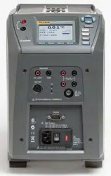
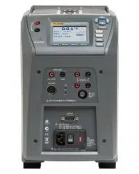
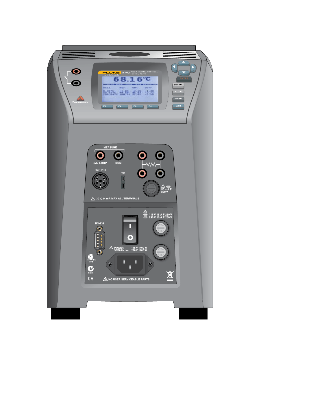
914X Field Metrology WellFigure 2
Parts and Controls3.2
This section describes the exterior features of the Field Metrology Well. All interface and power
connections are found on the front of the instrument (see Figure 2).
1.888.610.7664 sales@GlobalTestSupply.com
Fluke-Direct.com

19
Quick Start
Parts and Controls
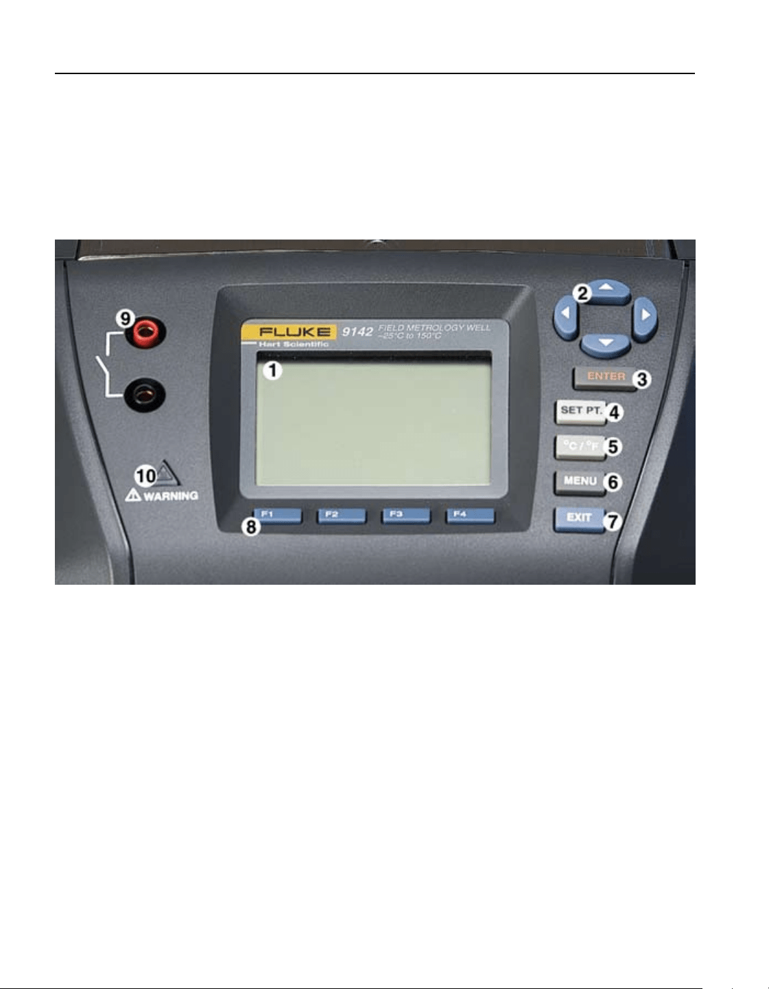
Display Panel3.2.1
Figure 3 on next page shows the layout of the display panel.
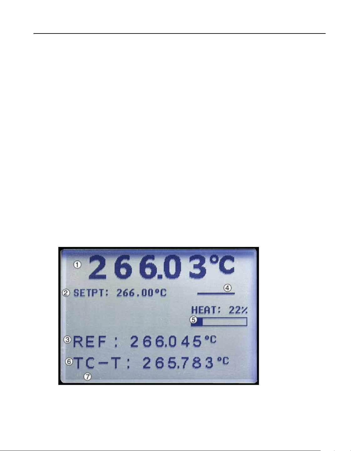
Display (1)
The display is a 240 x 160 pixel monochrome graphics LCD device with a bright LED back-
light. The display is used to show current control temperature, measurements, status informa-
tion, operating parameters, and soft key functions.
udlr Arrow Keys (2)
The Arrow Keys allow you to move the cursor on the display, change the display layout, and
adjust the contrast of the display. The contrast can only be adjusted using the u and d arrow
keys while viewing the main display window.
Enter Key (3)
The Enter Key allows you to select menus and accept new values.
SET PT. (4)
The Set Pt. Key allows you to enable the instrument to heat or cool to a desired set-point. Until
this key is enabled, the instrument will not heat or cool. It is in a “sleep” state for safety of the
operator and instrument.
°C/°F Key (5)
The °C/°F Key allows you to change the displayed temperature units from °C to °F and vice
versa.
Menu Key (6)
The Menu Key allows the user to access all parameter and settings menus. From the main
menu, the user can use the soft keys to access submenus and functions.
Exit Key (7)
The Exit Key allows you to exit menus and cancel newly entered values.
Soft Keys (8)
The Soft Keys are the four buttons immediately below the display (labeled F1 to F4). The func-
tions of the soft keys are indicated on the display above the buttons. The function of the keys
may change depending on the menu or function that is selected.
Switch Connector (9)
The switch hold connector posts are located on the left side of the display panel.
1.888.610.7664 sales@GlobalTestSupply.com
Fluke-Direct.com
914X Field Metrology Wells
Parts and Controls
20
Block Temperature Indicator (10) [Patent Pending]
The Block Temperature Indicator lamp allows users to know when the block temperature is
safe (50°C to 60°C) to remove inserts or move the Field Metrology Well. The indicator light is
lit continuously once the block has exceeded approximately 50°C (varies 50°C to 60°C). The
indicator light stays lit until the block cools to less than approximately 50°C. If the instrument
is disconnected from mains power, the indicator light ashes until the block temperature is less
than approximately 50°C.
Display panel and keys Figure 3
Display3.2.2
The front panel display is shown in detail in Figure 4 on opposite page.
Heat Source Temperature (1)
The most recent block temperature measurement is shown in large digits in the box at the top of
the screen.
Set-point Temperature (2)
The current set-point temperature is displayed just below the Process Temperature.
Reference Thermometer Temperature (3) [-P models only]
When installed, the most recent reference thermometer measurement is shown on the screen.
1.888.610.7664 sales@GlobalTestSupply.com
Fluke-Direct.com
21
Quick Start
Parts and Controls
Stability Status (4)
On the right hand side of the screen, you will nd a graph displaying the current status of the
stability of the Field Metrology Well.
Heating/Cooling Status (5)
Just below the stability graph there is a bar graph that will indicate HEATING, COOLING, or
CUTOUT. This status graph indicates the current level of heating or cooling if the instrument is
not in cutout mode.
UUT Output (6) [-P models only]
When installed, the most recent UUT output measurement is shown. The value displayed de-
pends on the output type selected: mA, RTD, or TC.
Soft Key Functions (7)
The four texts at the bottom of the display (not shown) indicate the functions of the soft keys
(F1–F4). These functions change with each menu.
Editing Windows
While setting up and operating the instrument, you are often required to enter or select param-
eters. Editing windows appear on the screen when necessary to show the values of parameters
and allow edits.
914X displayFigure 4
1.888.610.7664 sales@GlobalTestSupply.com
Fluke-Direct.com

914X Field Metrology Wells
Parts and Controls
22
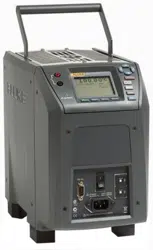
Power Panel3.2.3
The following are found on the lower front panel of the instrument (see Figures 5 and Figure 6
on opposite page).
Power Cord Plug (1)
The power supply cord attaches to the lower front power panel. Plug the cord into an AC mains
supply appropriate for the voltage range as specied in the specications tables.
Power Switch (2)
For the 9142, the power switch is located on the power entry module of the unit at the lower
center of the power panel.
For the 9143 and 9144, the power switch is located between the RS-232 and the fuses.
Serial Connector (3)
On the 9142, the serial connector is a 9-pin subminiature D type located on the power panel
above the power entry module. On the 9143 and 9144, the serial connector is a 9-pin submin-
iature D type located on the power panel to the left of the power switch. The serial (RS-232)
interface can be used to transmit measurements and control the operation of the instrument.
Fuses (4)
For the 9142, the fuses are located inside the power entry module of the unit (Figure 5 on op-
posite page).
For the 9143 and 9144, the fuses are separate from the power connector (Figure 6 on opposite
page).
If necessary, fuses must be replaced according to Specications (see Section 2.1 Specications
on page 13.
1.888.610.7664 sales@GlobalTestSupply.com
Fluke-Direct.com
23
Quick Start
Parts and Controls
Figure 5 9142 power panel
Figure 6 9143 and 9144 power panel
1.888.610.7664 sales@GlobalTestSupply.com
Fluke-Direct.com
914X Field Metrology Wells
Parts and Controls
24
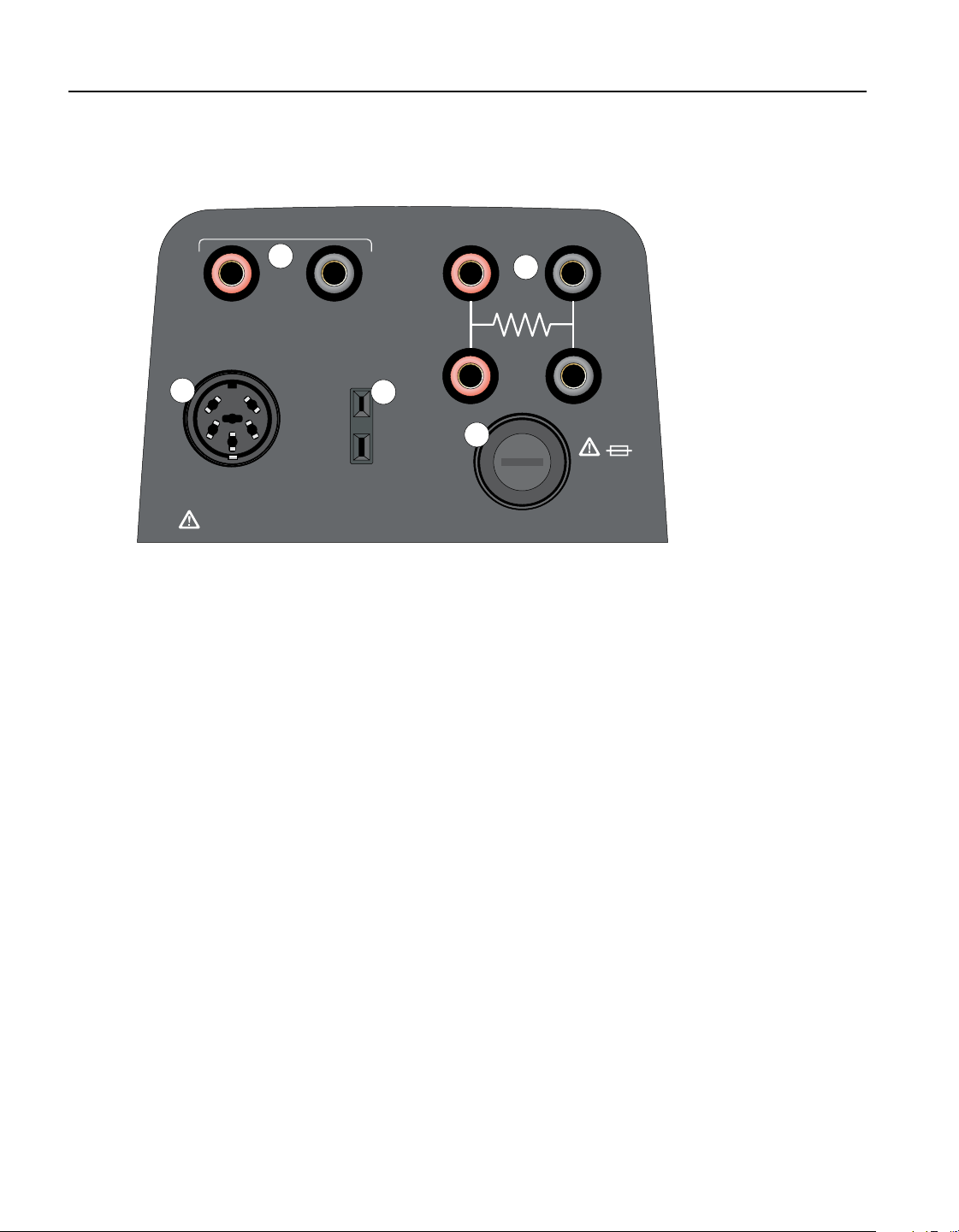
-P Option Panel (-P models only)3.2.4
The –P (process version) panel is the readout portion of the instrument and is only available
with –P models.
REF PRT
TC
COM
mA LOOP
MEASURE
30 V, 24 mA MAX ALL TERMINALS
50 mA F
250 V
F
U
S
E
F
U
S
E
1
2
3
4
5
Figure 7 -P option panel
Reference Thermometer Connection (1)
The 6-pin DIN smart connector on the front panel allows a reference probe to be attached to the
instrument for use with the reference thermometer function of the instrument. The smart con-
nector stores probe calibration coefcients. The 6-pin DIN accepts traditional connectors and
the probe coefcients can be entered into the readout or an appropriate characterization curve
can be selected through the user interface (see Section 1.5.2 Immunity Testing on page 8 for
information on using clamp-on ferrites).
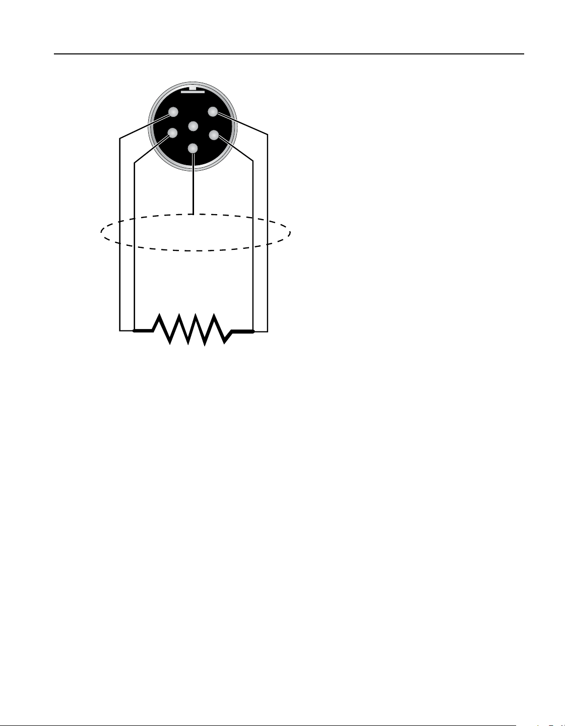
A PRT is the only type of probe that is supported by the reference thermometer input. The PRT
(RTD or SPRT) probe connects to the reference thermometer input using a 6-pin DIN connec-
tor. Figure 8 shows how a four-wire probe is wired to the 6-pin DIN connector. One pair of
wires attaches to pins 1 and 2 and the other pair attaches to pins 4 and 5 (pins 1 and 5 source
current and pins 2 and 4 sense the potential). If a shield wire is present, it should be connected
to pin 3, which is also used for the memory circuit. Pin 6 is only used for the memory circuit.
1.888.610.7664 sales@GlobalTestSupply.com
Fluke-Direct.com
25
Quick Start
Parts and Controls
Figure 8
1
2
4
5
RTD Sensor
Probe Connector
3
Shield
6
Probe connector wiring
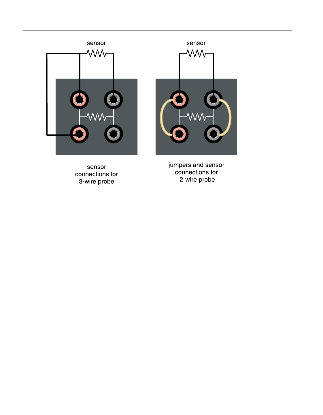
A two-wire probe can also be used with the reference thermometer. It is connected by attach-
ing one wire to both pins 1 and 2 of the plug and the other wire to both pins 4 and 5. If a shield
wire is present, it should be connected to pin 3. Accuracy may be signicantly degraded using a
two-wire connection because of lead resistance.
4-20mA Connectors (2)
The 4-20mA connectors allow current and/or voltage probes to be connected for measurement
of associated devices.
PRT/RTD Connector (3)
The 4-wire PRT/RTD connectors allow the user to connect 3-wire and 2-wire (with jumpers,
see Figure 9 on next page) PRT/RTDs to the readout. The correct wiring for the 4-wire PRT/
RTD is shown on the instrument. Figure 9 shows the correct wiring for a 2 or 3-wire PRT/RTD
(see Section 1.5.2 Immunity Testing on page 8 for information on using clamp-on ferrites).
1.888.610.7664 sales@GlobalTestSupply.com
Fluke-Direct.com
914X Field Metrology Wells
Languages
26
Figure 9 Jumper locations for 3-wire and 2-wire connections
Thermocouple (TC) Connector (4)
The TC connector allows for the use of subminiature TC connectors (see CE Comments on
page 8 for information on using clamp-on ferrites).
Fuse (5)
Fuse for the 4-20 mA circuit. Always replace with a fuse of the appropriate rating (see Section
2.1 Specications on page 13).
Languages3.3
The display on Field Metrology Wells can be set to different languages depending on the
conguration.
European: English, French, Spanish, Italian, German
●●
Russian: Russian, English
●●
Asian: English, Chinese, Japanese
●●
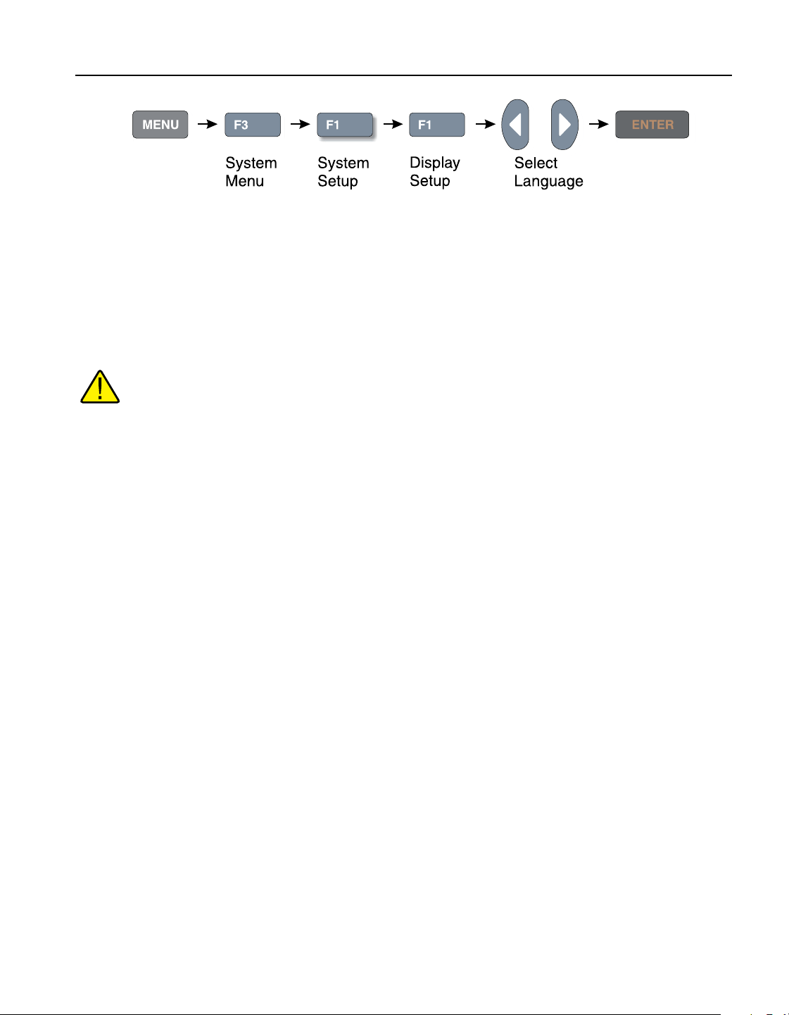
Language Selection3.3.1
Select the language to be displayed by following the steps shown in Figure 10 on opposite
page.
1.888.610.7664 sales@GlobalTestSupply.com
Fluke-Direct.com
27
Quick Start
Languages
Figure 10 Steps to language selection
Reset to English Language3.3.2
If you are in a language and need a short cut exit, press F1 and F4 simultaneously to reset the
display to English.
To reset to your originally selected language after resetting to English, follow the steps in
Figure 10 on this page.
Note: The F1 and F4 English shortcut override is temporary. If you toggle the power off,
the instrument jwill return to the language selected in the DISPLAY SETUP menu rather
than coming up in English.
1.888.610.7664 sales@GlobalTestSupply.com
Fluke-Direct.com

1.888.610.7664 sales@GlobalTestSupply.com
Fluke-Direct.com

29
Menu Structure
Temp Setup Menu
Menu Structure4
Temp Setup Menu4.1
9142/9143/9144 MAIN MENU
F1 F2 F3 F4
TEMP SETUP PROG MENU SYSTEM MENU INPUT SETUP (-P only)
F1 SETUP
SCAN RATE: <edit> Degrees per minute at which the Field Metrology Well increases or decreases temperature
STABLE LIMIT: <edit> The defined minimum stability over a 2 minute period before alarm is activated
STABLE ALARM: <ENABLE, DISABLE> <select> Audible alarm indicating the Field Metrology Well is stable
F2 CUTOUT
SOFT CUTOUT: <edit> User adjustable safety cutout
HARD CUTOUT: <view only> Factory set safety cutout
Hot Keys (while viewing main screen)
SETPoinT. Key - SETPOINT
SETPOINT:
<edit> Set point temperature
ENTER <enable control of the instrument>
F1 – SELECT PRESET <1-8> <select>
F1 – EDIT PRESET <1-8> <edit>
F4 – SAVE/DISABLE <disables control of instrument>
ºC / ºF Key - Units: <°C, °F> Changes temperature units
Up/Down Arrow Keys <toggle> <adjust contrast>
Up Key: Darker
Down Key: Lighter
F1 & F4 Keys (same time) <reset display language to English>
F1 & F3 Keys (same time) <enable/disable key press beep>
1 Beep – Valid key entry
2 Beep – Invalid key entry
Code Update Mode Keys
ENTER & EXIT Keys (hold during power up) <initiate code update mode> Allows instrument software to be updated
Figure 11 Main Menu - Temp SetUp
1.888.610.7664 sales@GlobalTestSupply.com
Fluke-Direct.com

914X Field Metrology Wells
Prog Menu
30
Prog Menu4.2
9142/9143/9144 MAIN MENU
F1 F2 F3 F4
TEMP SETUP PROG MENU SYSTEM MENU INPUT SETUP (-P only)
F1 RUN PROGram
TEST STATUS: <OFF, RUN> <select> Changes status of current test
RUN TEST: <RAMP/SOAK, SWITCH TEST> <select> Runs selected test
RECORD DATA: <YES, NO> <select> (-P only) Records data for ramp/soak or switch tests.
TEST ID: < Text, 16 char, English ASCII only > <edit> (-P only) Alpha-numeric identification for test
F2 RAMP/SOAK
Number O.f SETPOINTS: <1-8> <select>
SOAK TIME: <minutes> <edit> Length of time in minutes at which the Field Metrology Well remains at the set point temperature
Number O.f CYCLES: <1-999> <select> Number of times the Field Metrology Well repeats the ramp/soak program
DIRECTION: <
Æ
, > <select>
PASS TOLERANCE±: <edit> (-P only) Pass/Fail criteria for the ramp/soak program
F1 SET POINTS
SETPOINT 1: <edit>
SETPOINT 2: <edit>
SETPOINT 3: <edit>
SETPOINT 4: <edit>
SETPOINT 5: <edit>
SETPOINT 6: <edit>
SETPOINT 7: <edit>
SETPOINT 8: <edit>
F3 SWITCH TEST
TEST METHOD: <AUTO, MANUAL> <select>
F1 AUTO TEST
SWITCH TEMPerature: <nominal temperature> <edit> Run automated 3-cycle test based on the nominal temperature of the switch
F2 MANUAL TEST (Run automated test based on test parameters set below)
UPPER TEMPerature: <edit> Upper temperature range in which encompasses a change of state for the temperature switch
LOWER TEMPerature: <edit> Lower temperature range in which encompasses a change of state for the temperature switch
APPROACH LIMIT: <edit> Temperature parameter in relation to the upper and lower temperature in which the system scan rate will be used
Number O.f CYCLES: <1-100> <edit> Number of times the Field Metrology Well repeats the manual test program
F4 TEST RESULT (-P only)
F1
VIEW TESTS
DISPLAY TEST: <1-16> <select> Displays test results
DATE: <view only>
TIME: <view only>
F2 PRINT TESTS
PRINT TESTS: < NO, YES> <select> Print all test data to RS-232 port
F3 ERASE TESTS
ERASE TESTS: <NO, YES> <select> Erases all test data
Figure 12 Main Menu - Prog Menu
1.888.610.7664 sales@GlobalTestSupply.com
Fluke-Direct.com

31
Menu Structure
Prog Menu
Switch Test Parameters4.2.1
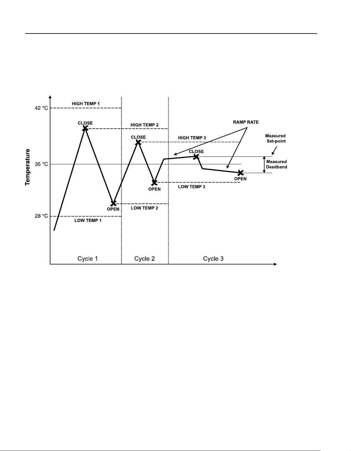
SWITCH TEMP
The SWITCH TEMP parameter is the nominal change temperature of the switch.
UPPER TEMP
The UPPER TEMP parameter is the temperature during a cycle at which the Field Metrology
Well begins to heat or cool at the rate specied in “Scan Rate” found in MAIN MENU|TEMP
SETUP|SETUP|SCAN RATE.
LOWER TEMP
The LOWER TEMP parameter is the temperature at which the Field Metrology Well heats or
cools, in order to begin testing if the test is just starting or the temperature at which the instru-
ment begins to heat to start a cycle.
APPROACH
The APPROACH parameter controls the use of the Scan Rate during the approach to the set-
point. During the test, the controller uses the system Scan Rate until the temperature is within
the approach temperature of either the high temp or low temp parameters.
NO. CYCLES
The NO. CYCLES parameter determines how many times the instrument heats and cools al-
lowing a thermal switch or batch of switches to be tested.
Switch Test Description4.2.2
CAUTION: The switch, switch wires, switch components and switch accessories can be
damaged if the Field Metrology Well exceeds their temperature limits.
The SWITCH TEST is used to select, set up, execute and view the results of switch tests. The
Switch Test function allows thermal switches to be tested for open and/or close temperatures.
The Switch Test allows for Auto or Manual operation. Figure 13 on next page shows a graphi-
cal representation of how a switch test works.
For Auto operation, enter the Prog Menu. Under Switch Test, select Auto Test. Enter the
SWITCH TEMP. Set the Test Method to AUTO. Exit to the Run Prog menu. Ensure that Run
Test is set to SWITCH TEST. Set Test Status to RUN. Press Enter and the instrument will
engage and start the 3-cycle test within a few seconds. Exit to the main screen to view the test
progress, refer to the Menu Structure.
For Manual operation, in the Temp Setup menu, select Setup and enter the SCAN RATE. Exit
to the Prog Menu. Under Switch Test, select Manual Test. Enter the UPPER TEMP, LOWER
TEMP, APPROACH LIMIT, and NO. CYCLES parameters. Set the Test Method to MANUAL.
Exit to the Run Prog menu. Ensure that the Run Test is set to SWITCH TEST. Set Test Status to
1.888.610.7664 sales@GlobalTestSupply.com
Fluke-Direct.com
914X Field Metrology Wells
Prog Menu
32
RUN. Press Enter and the instrument will engage and start the test within a few seconds. Exit to
the main screen to view the test progress, refer to the Menu Structure.
When the switch resets, the test completes and the values of the switch OPEN, switch CLOSE,
and switch BAND are displayed for the user to record. The values may also be recorded inter-
nally in the instrument by selecting the option to record the data (-P model only).
Figure 13 Auto and manual switch test operation example
1.888.610.7664 sales@GlobalTestSupply.com
Fluke-Direct.com
33
Menu Structure
System Menu
System Menu4.3
9142/9143/9144 MAIN MENU
F1 F2 F3 F4
TEMP SETUP PROG MENU SYSTEM MENU INPUT SETUP (-P only)
F1 SYSTEM SETUP
F1 DISPLaY SETUP
LANGUAGE: <English, Japanese, Chinese, German, Spanish, French, Russian, Italian> <select>
DECIMAL: <PERIOD, COMMA> <select>
KEY AUDIO: <ON, OFF> <select>
F2 COMMunication SETUP
BAUD RATE: <1200, 2400, 4800, 9600, 19200, 38400> <select>
LINEFEED: <ON, OFF> <select>
F3 DATE TIME (-P only)
TIME: <24 hour time only> <edit>
DATE: <edit>
DATE FORMAT: <MM/DD/YYYY, DD/MM/YYYY> <select>
TIME STAMP: <ENABLE, DISABLE> <select>
F2 PASSWORD
USER PASSWORD: <edit>
PROTECTION: <LOW, HIGH> <select>
F3 CALIBration
F1 CALPOINTS
TEMPerature 1: <edit>
TEMPerature 2: <edit>
TEMPerature 3: <edit>
GRADient 1: <edit>
GRADient 2: <edit>
GRADient 3: <edit>
GRADient 4: <edit> (9144 only)
GRADient 5: <edit> (9144 only)
CALibration DATE: <edit> <yyyy.mm.dd>
F2 CONTRoLler
TEMPerature Proportional Band: <edit>
TEMPerature INTegration: <edit>
TEMPerature DERivative: <edit>
F3 CALibration REFerence (-P only)
REF C0: <edit>
REF C100: <edit>
INPUT CALibration DATE: <edit> < yyyy.mm.dd >
F4 CALibration UUT (-P only)
F1 CALibration TC
TC C0: <edit>
TC C100: <edit>
TC CRJ: <edit>
INPUT CALibration DATE: <edit> < yyyy.mm.dd >
F2 CALibration mA
mA C4: <edit>
mA C22: <edit>
INPUT CALibration DATE: <edit> < yyyy.mm.dd >
F4 SYSTEM INFO
<view only>
MODEL: <view only>
SERIAL number: <view only>
FirmWare VERsion: <view only>
CALibration DATE: <view only>
INPUT CALibration DATE: : <view only> (-P only)
Figure 14 Main Menu - System Menu
1.888.610.7664 sales@GlobalTestSupply.com
Fluke-Direct.com

914X Field Metrology Wells
Input Setup (-P only)
34
Input Setup (-P only)4.4
9142/9143/9144 MAIN MENU
F1 F2 F3 F4
TEMP SETUP PROG MENU SYSTEM MENU INPUT SETUP (-P only)
F1 SELECT INPUT
SENSOR TYPE: <RTD, TC, mA> <select>
F2 SETUP INPUT
F1 RTD SETUP
WIRES: <4, 2, 3> <select>
RTD TYPE: <RESISTANCE, PT100(385), PT100(3926), PT100(JIS), NI-120> <select>
F2 TC SETUP
TC TYPE: <K, L, M, N, R, S, T, U, mV, C, E, J> <select>
F3 mA SETUP
LOOP POWER: <DISABLE, ENABLE 24V> <select>
F4 TEST uut CALCulation
SENSOR TYPE: <RTD, TC> <select>
INPUT: <edit> <ohms if RTD, mV if TC is selected>
TEMPerature: <calculated value displayed> <view only>
F3 REFerence INPUT
F1 PROGram PROBE
SERIAL number: <edit> <alphanumeric>
CALibration DATE: <edit>
PROBE TYPE: <ITS-90, CVD, IEC-751, RESISTANCE> <select>
List:
ITS-90 CVD IEC751 RESISTANCE
RTPW R0
A ALPHA
B BETA
C DELTA
A4
B4
PROGRAM probe
<YES, NO> <password required to program probe>
F2 TEST reference CALCulation
RESISTANCE: <edit>
TEMPERATURE: <calculated value displayed> <view only>
Figure 15 Main Menu - Input Setup
1.888.610.7664 sales@GlobalTestSupply.com
Fluke-Direct.com

35
Maintenance
Field Metrology Well Performance Analysis
5 Maintenance
The Field Metrology Well has been designed with the utmost care. Ease of operation and sim-
plicity of maintenance have been a central theme in the product development. With proper care,
the instrument should require very little maintenance. Avoid operating the instrument in an oily,
wet, dirty, or dusty environment. Operating the instrument in a draft-free environment facili-
tates improved performance of the instrument.
If the outside of the instrument becomes soiled, it may be wiped clean with a damp cloth
●●
and mild detergent. Do not use harsh chemicals on the surface which may damage the
paint or plastic.
It is important to keep the well of the calibrator clean and clear of any foreign matter.
●●
DO NOT use uid to clean out the well.
The instrument should be handled with care. Avoid knocking or dropping the calibrator.
●●
The removable inserts can become covered with dust and carbon material. If the buildup
●●
becomes too thick, it could cause the inserts to become jammed in the wells. Avoid this
build up by periodically bufng the inserts clean.
If an insert should be dropped, examine the insert for deformities before inserting it in
●●
the well. If there is any chance of jamming the insert in the well, le or grind off the
protuberance.
DO NOT allow the probe stems to drop into the well or harshly impact the well bottom.
●●
This type of action can cause a shock to the sensor.
If a hazardous material is spilled on or inside the instrument, the user is responsible for
●●
taking the appropriate decontamination steps as outlined by the national safety council
with respect to the material.
If the mains supply cord becomes damaged, replace it with a cord of the appropriate
●●
gauge wire for the current of the instrument. If there are any questions, contact an
Authorized Service Center for more information.
Before using any cleaning or decontamination method, other than those recommended by
●●
Fluke’s Hart Scientic Division, users should check with an Authorized Service Center
to insure the proposed method will not damage the equipment.
If the instrument is used in a manner not in accordance with the equipment design, the
●●
operation of the instrument may be impaired or safety hazards may arise.
The over-temperature cutout should be checked every 6 months to see that it is working
●●
properly. In order to check the user selected cutout, follow the controller directions for
setting the cutout. Set the instrument temperature higher than the cutout. Check to see if
the display shows cutout and the temperature is decreasing.
Field Metrology Well Performance Analysis5.1
For optimum performance and lowest possible uncertainty budgets, use the guidelines set forth
below.
1.888.610.7664 sales@GlobalTestSupply.com
Fluke-Direct.com

914X Field Metrology Wells
Field Metrology Well Performance Analysis
36
Accuracy Drift
The display temperature of the instrument will drift over time. This is due to a variety of factors
affecting the temperature control PRT. Any PRT is subject to changes depending on how it is
used and the environment it is used in. This is no different for any PRT in a calibration appli-
cation. In addition, manufacturing variables in the sensing element itself can result in greater
or lesser impact from use and environment. Oxidation and contamination from the sensor’s
environment will create changes requiring new calibration constants depending on the tempera-
ture range and normal operation of the instrument. Oxidation and contamination are generally
not factors when Field Metrology Wells are used exclusively below 200°C. Oxidation can form
in the body of the PRT platinum sensor wire in the range of 300 °C to 500 °C. Contamination
is primarily a problem following prolonged use above 500°C. Additionally, vibration from
handling or transportation will strain the delicate PRT element, changing its resistance. Some
of this strain may come out by annealing at a slightly higher temperature than the instrument
is typically used at. It is recommended to avoid unnecessary temperature cycling. Cycling the
temperature up and down between minimum and maximum temperatures excessively may also
cause strain on the PRT element.
Effects from control sensor drift may be avoided by using an external temperature reference. In
the case that the calibration of the display value is required, a program of monitoring and recali-
bration must be implemented, just as with any calibration standard. Regularly check the accu-
racy of the Field Metrology Well with an adequate temperature reference and keep records as a
part of your instrument maintenance routine. When the accuracy drifts to a point where it is no
longer acceptable, then have the instrument recalibrated. Your records will provide data for de-
termining a calibration interval appropriate for your history of use and accuracy requirements.
Stability
The stability specication of the Field Metrology Well was determined under laboratory condi-
tions of steady ambient temperature and air ow. While this instrument has been designed to
minimize ambient effects, they will still have some effect. For the best results, avoid quickly-
changing ambient temperatures and drafty conditions.
Axial Uniformity
Field Metrology Well axial uniformity should be checked periodically. Use the process outlined
in EA 10/13 or a similar process. If the axial uniformity has changed outside the limits set by
the user’s uncertainty budget, adjust the axial gradient as outlined in the Field Metrology Well
Calibration section of the Field Metrology Well Technical Guide and recalibrate the Field Me-
trology Well.
1.888.610.7664 sales@GlobalTestSupply.com
Fluke-Direct.com