Before attempting to connect or operate this product,
please read these instructions carefully and save this manual for future use.
UBN-QG-K
Quick Start Guide
GV-IP Camera
GV-EBD Series
GV-ABL / TBL Series
GV-ADR / TDR Series
GV-AVD / TVD Series
© 2019 GeoVision, Inc. All rights reserved.
Under the copyright laws, this manual may not be copied, in whole or in part,
without the written consent of GeoVision.
Every effort has been made to ensure that the information in this manual is
accurate. GeoVision, Inc. makes no expressed or implied warranty of any kind
and assumes no responsibility for errors or omissions. No liability is assumed
for incidental or consequential damages arising from the use of the information
or products contained herein. Features and specifications are subject to
change without notice.
Note: No memory card slot or local storage function for Argentina.
GeoVision, Inc.
9F, No. 246, Sec. 1, Neihu Rd.,
Neihu District, Taipei, T
aiwan
Tel: +886-2-8797-8377
Fax: +886-2-8797-8335
http://www.geovision.com.tw
Trademarks used in this manual: GeoVision, the GeoVision logo and GV
series products are trademarks of GeoVision, Inc. Windows is the registered
trademark of Microsoft Corporation.
June 2019

i
Contents
Note for Connecting to GV-VMS / DVR / NVR........................................................ ii
Note for Installing Camera Outdoor ....................................................................... ii
Note for Powering the Camera ............................................................................... ii
Note for Face Detection ......................................................................................... iii
Note for People Counting ...................................................................................... iv
1. GV-EBD Series .................................................................................................. 1
1.1 Packing List................................................................................................... 2
1.2 Overview....................................................................................................... 3
1.2.1 GV-EBD2702 / 4700 / 8700 ............................................................................................3
1.2.2 GV-EBD4711 / 8711.........................................................................................................4
1.3 Installation..................................................................................................... 5
1.3.1 GV-EBD2702 / 4700 / 8700 Installation ........................................................................ 5
1.3.2 GV-EBD4711 / 8711 Installation .....................................................................................8
2. GV-ABL / TBL Series........................................................................................11
2.1 Packing List................................................................................................. 12
2.2 Overview..................................................................................................... 13
2.2.1 GV-ABL2701 / 2703 / 4701 / 4703...............................................................................13
2.2.2 GV-ABL2702 / 4712 / 8712 / TBL Series .................................................................... 14
2.3 Installation................................................................................................... 15
3. GV-ADR / TDR Series...................................................................................... 18
3.1 Packing List................................................................................................. 19
3.2 Overview..................................................................................................... 20
3.3 Installation................................................................................................... 21
4. GV-AVD / TVD Series ...................................................................................... 24
4.1 Packing List................................................................................................. 25
4.2 Overview..................................................................................................... 26
4.3 Installation................................................................................................... 27
5. Waterproofing the Cable ................................................................................ 29
6. Accessing the Camera ................................................................................... 31
6.1 System Requirements ................................................................................. 31
6.2 Looking Up the Dynamic IP Address ........................................................... 32
6.3 Configuring the IP Address.......................................................................... 34
7. The Web Interface........................................................................................... 35
8. Upgrading System Firmware ......................................................................... 37
9. Restoring to Factory Default.......................................................................... 38
ii
Note for Connecting to GV-VMS / DVR / NVR
The GV-IPCAM is designed to work with and record on GV-VMS / DVR / NVR, a video
management system.
Once the camera is connected to the GV-VMS / DVR / NVR, the resolution set on
the GV-VMS / DVR / NVR will override the resolution set on the camera’s Web
interface. You can only change the resolution settings through the Web interface
when the connection to the GV-VMS / DVR / NVR is interrupted.
The login password of the camera cannot contain the character “&” when
connecting to GV-VMS.
The Video Analytic features under Intelligent (See 3.5 Intelligent in the User’s
Manual) cannot be integrated with GV-VMS / DVR / NVR
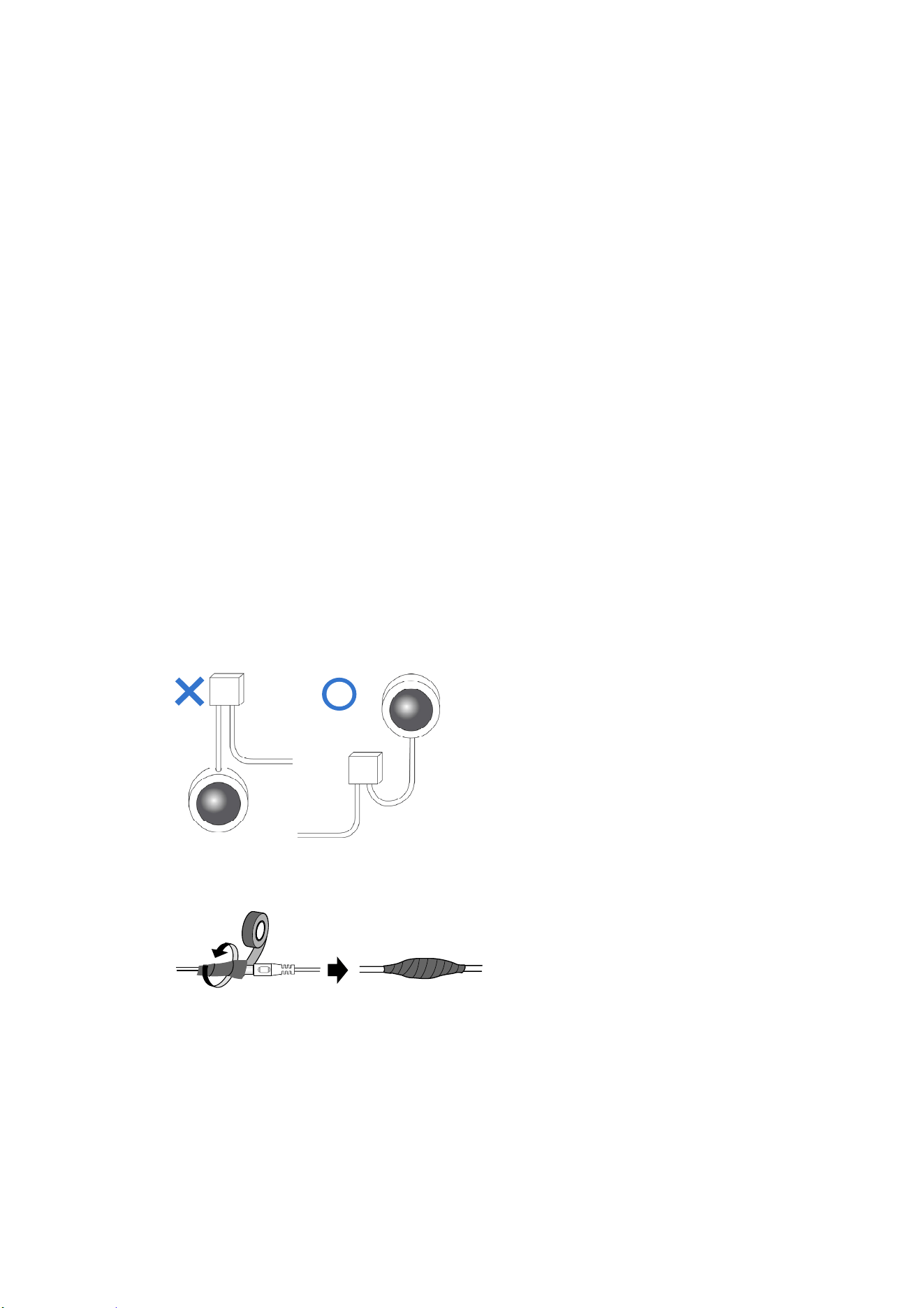
Note for Installing Camera Outdoor
When installing the camera outdoor, be sure that:
1. The camera is set up above the junction box to prevent water from entering the
camera along the cables.
2. Any PoE, power, audio and I/O cables are waterproofed using waterproof silicon
rubber or the like.
3. The screws are tightened and the cover is in place after opening the camera
cover.
Note for Powering the Camera
The Camera is powered by PoE. If you want to power the camera using the power
connector, an optional power adapter is required.
iii
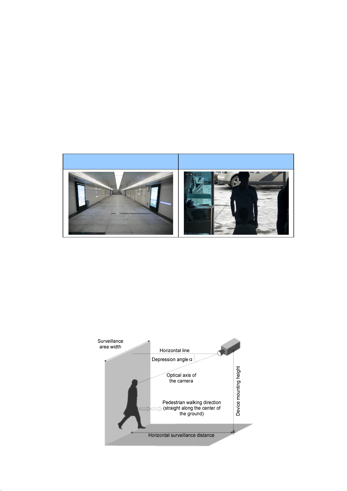
Note for Face Detection
To use the camera’s built-in face detection feature (see 3.5.1.7 Face Detection in the
User’s Manual), not supported by GV-ABL2701 / 2703 / 4701 / 4703, GV-ADR2701 /
2702 / 4701 / 4702, GV-TBL series and GV-TVD series, it is recommended to install
the camera according to the criteria listed below:
Surveillance Condition
The camera shall be installed at a site with uniform, sufficient lighting, where the
face(s) to be detected are fully illuminated.
Example of Recommended Scene Example of Non-recommended Scene
Camera Position
The camera shall be mounted at a recommended height of 2.5 ~ 3 m.
The camera shall be mounted with a recommended depression angle of around
10°.
The camera shall be positioned so that the face(s) to be detected are directly
aligned with the lens of the camera, with a horizontal deviation of no greater than
30°, a vertical deviation of no greater than 15° and a face size of at least 120
pixels.
iv
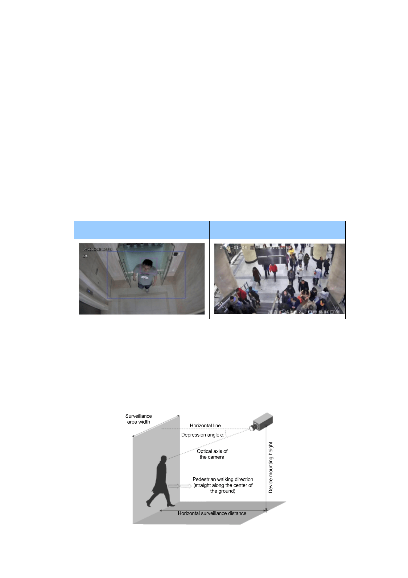
Note for People Counting
To use the camera’s built-in people counting feature (see 3.5.1.8 People Counting in
the User’s Manual), not supported by GV-ABL2701 / 2703 / 4701 / 4703,
GV-ADR2701 / 2702 / 4701 / 4702, GV-TBL series and GV-TVD series, it is
recommended to install the camera according to the criteria listed below:
Surveillance Condition
The camera shall be installed at a site with uniform, sufficient lighting, where the
person(s) to be counted are fully illuminated.
The camera shall be installed at an entrance or exit with an ideal width of 1 ~ 4 m,
where the persons(s) to be counted move toward the lens of the camera in single
file.
Example of Recommended Scene Example of Non-recommended Scene
Camera Position
The camera shall be mounted at a recommended height of 3 ~ 5 m.
The camera shall be mounted with a recommended depression angle of 70 ~ 80°.
The camera shall be positioned so that the person(s) to be counted face toward
the lens of the camera and are displayed on the image with a shoulder size of
between 120 ~ 160 pixels.
1
1. GV-EBD Series
Camera Type Model No.
GV-EBD2702 (IP67)
GV-EBD4700 (IP67)
GV-EBD4711 (IP67)
GV-EBD8700 (IP67)
Eyeball IP Dome
GV-EBD8711 (IP67)
2
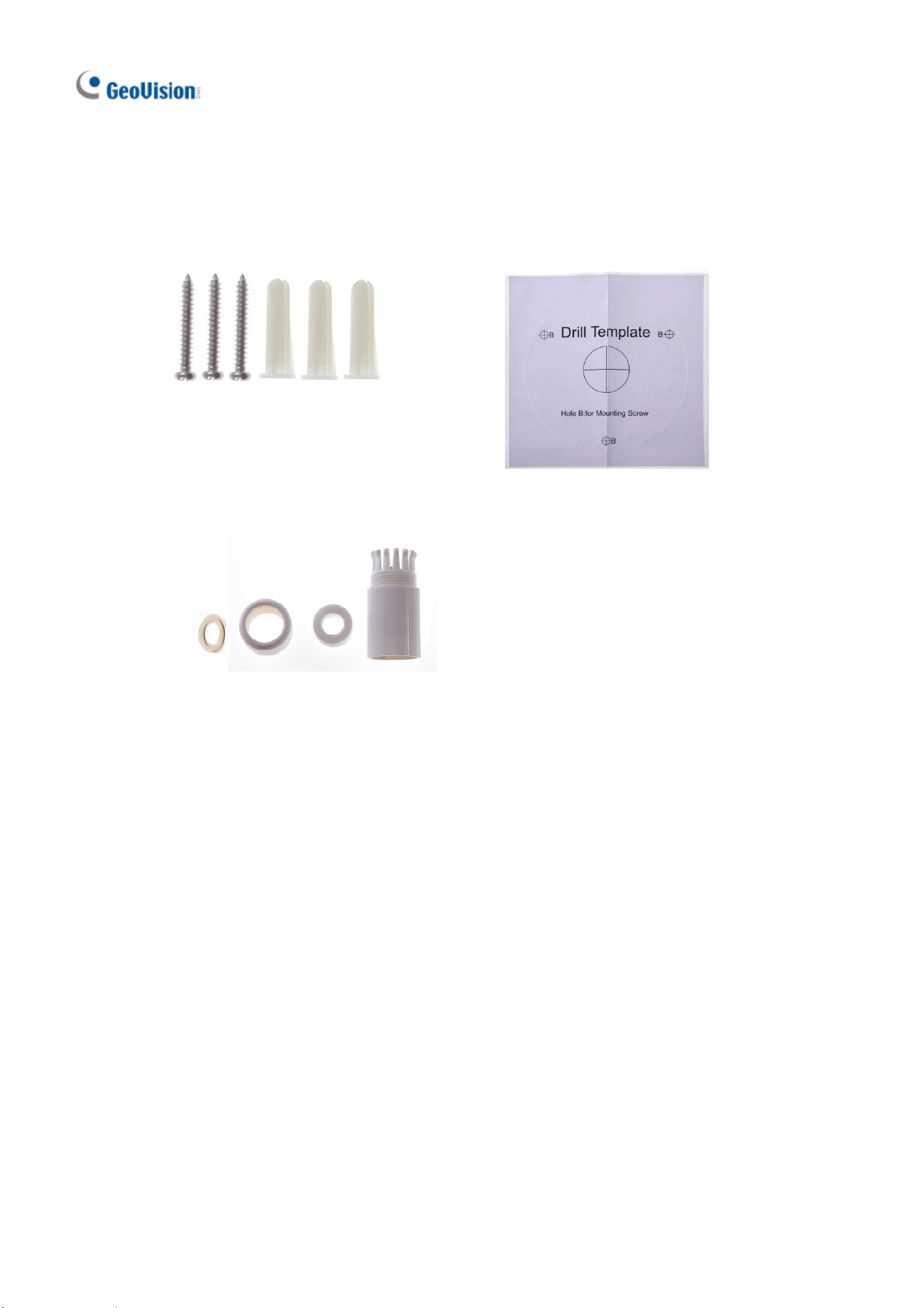
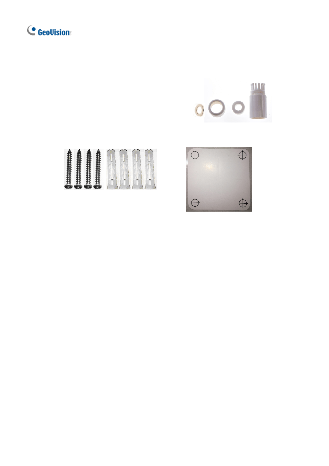
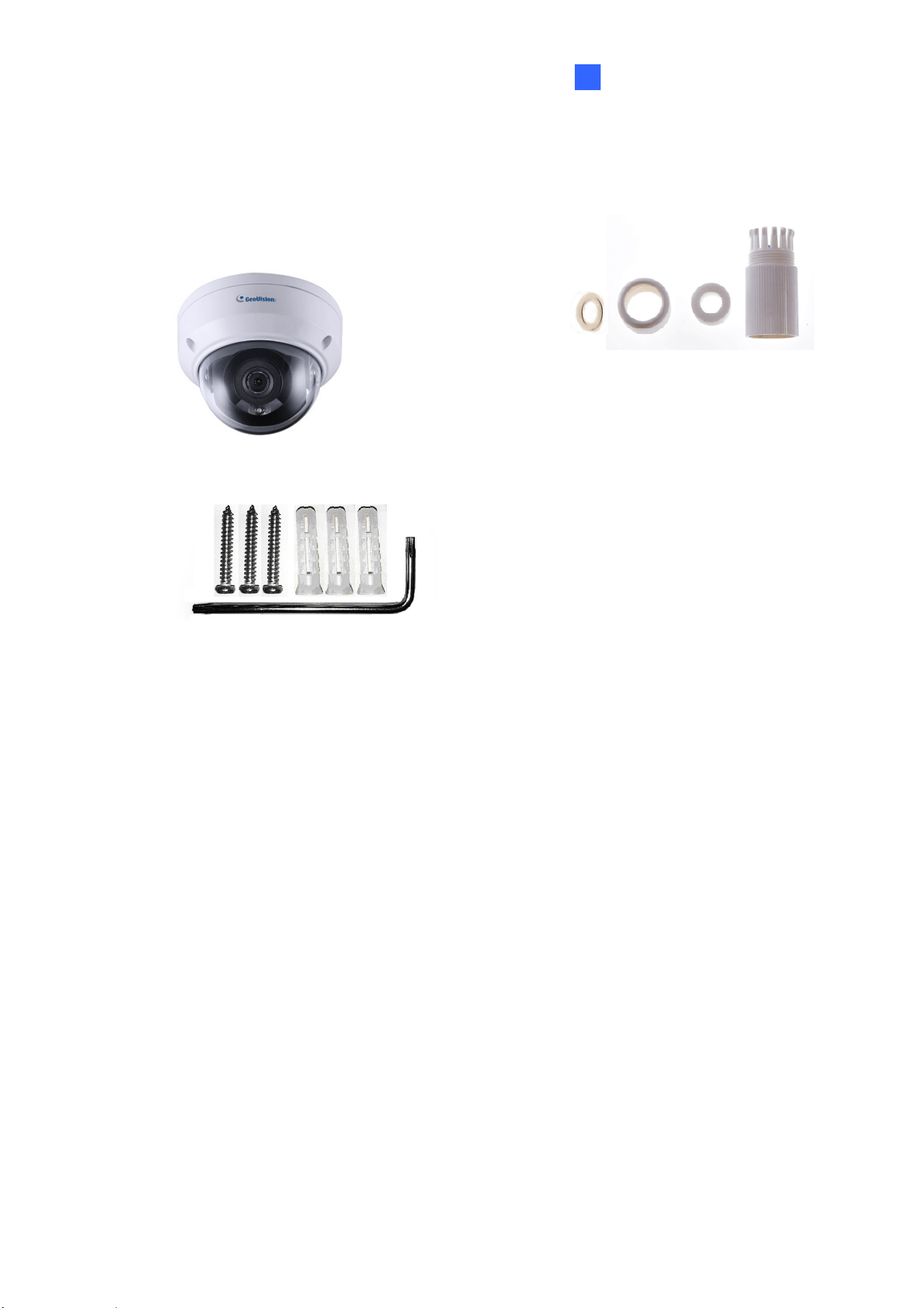
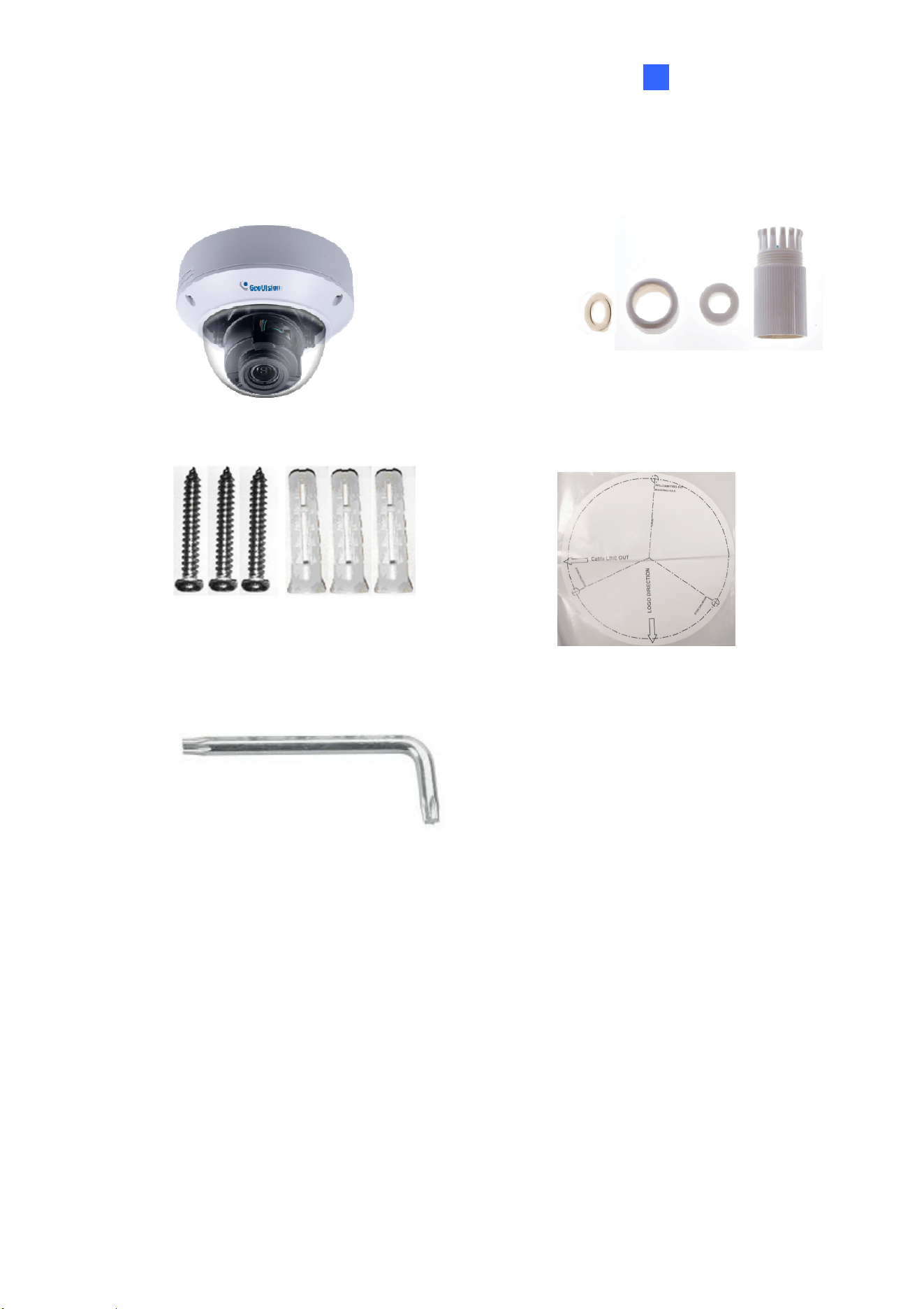
1.1 Packing List
H.265 Target Eyeball Dome
Screw Kit
Drill Template Paster
Waterproof Rubber Set
Download Guide
Warranty Card
GV-EBD Series
3
1
1.2 Overview
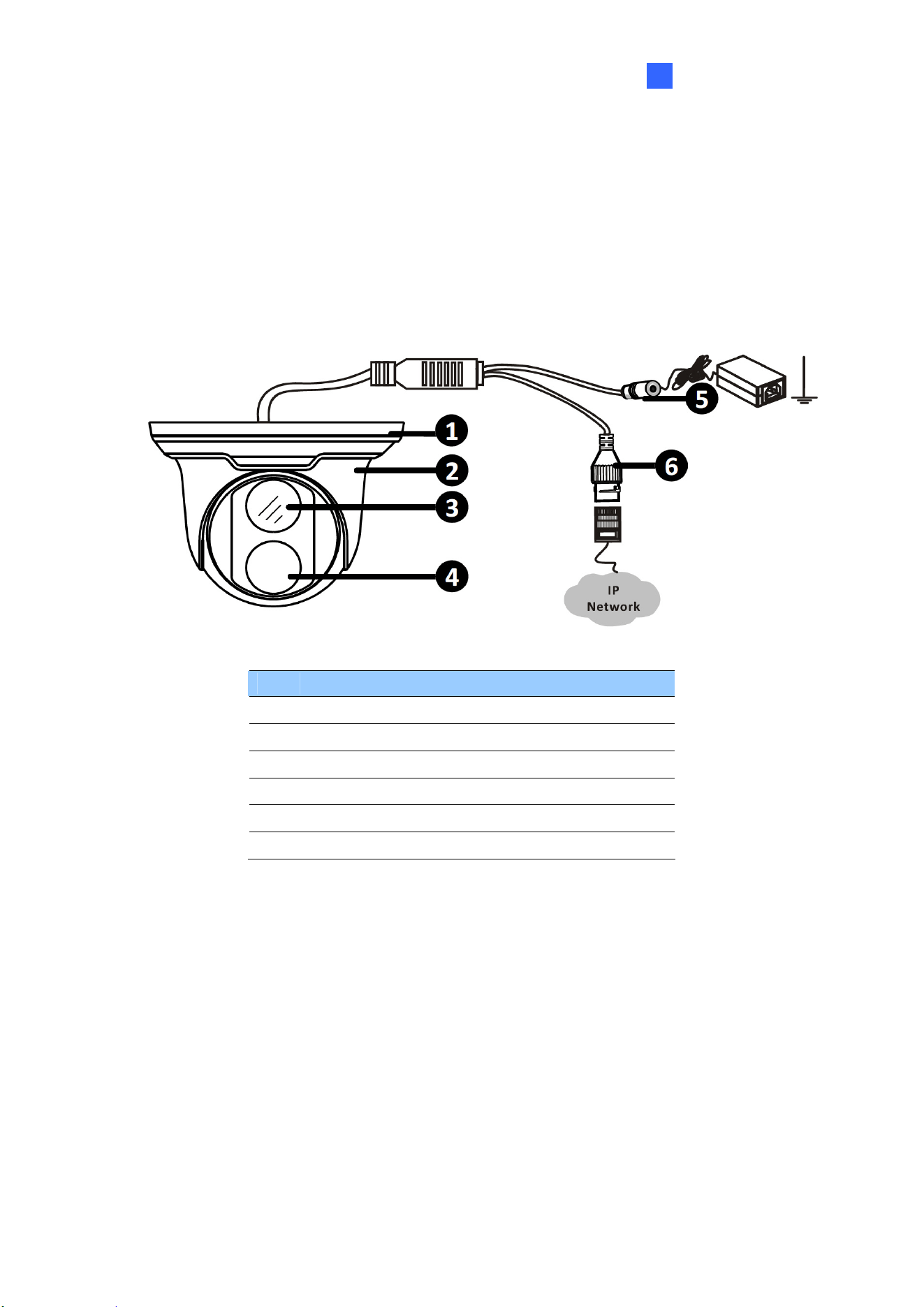
1.2.1 GV-EBD2702 / 4700 / 8700
No. Description
1 Bottom ring
2 Housing
3 Lens
4 Infrared indicator
5 Power connector (DC 12 V)
6 Ethernet connector / PoE
4
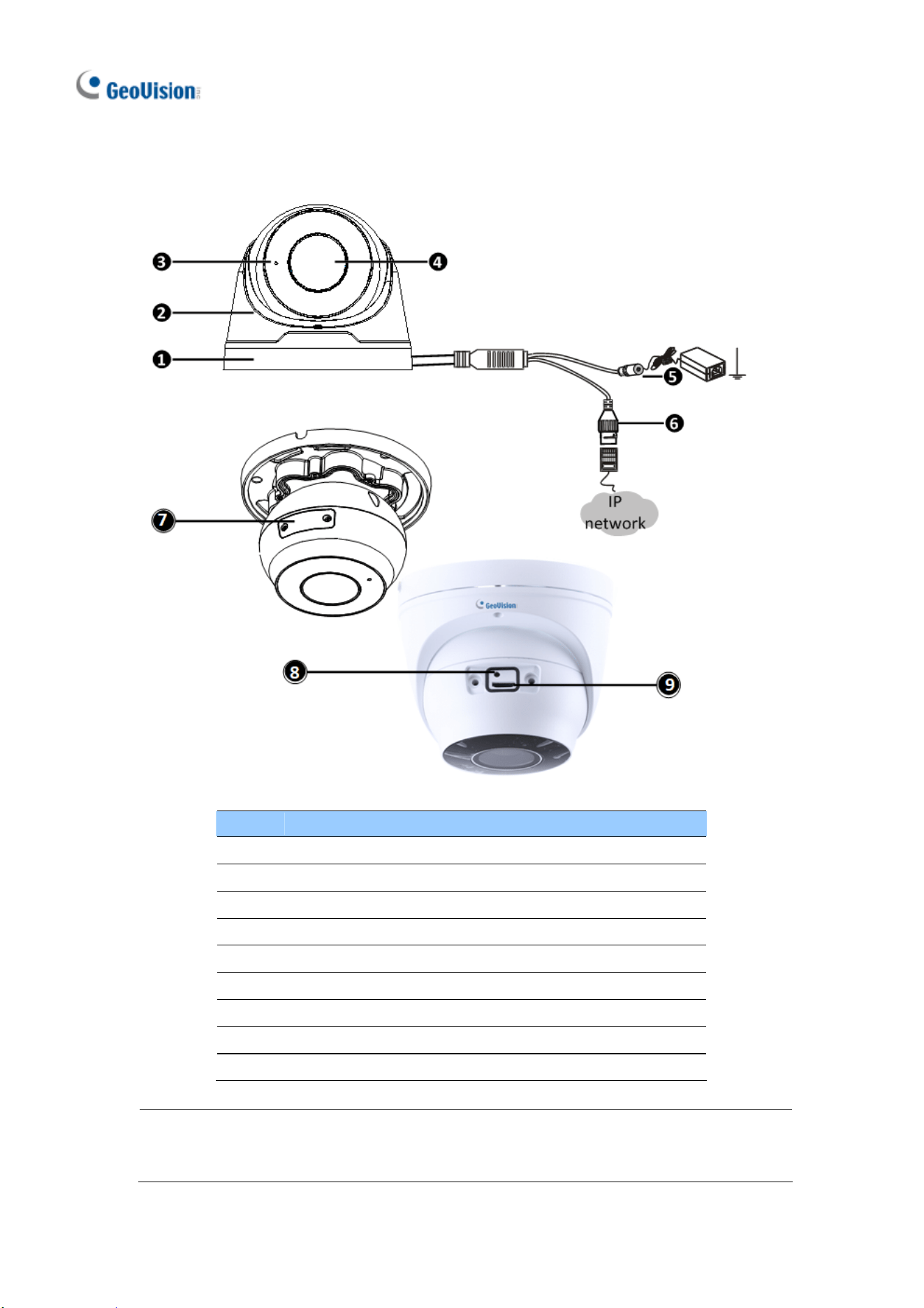
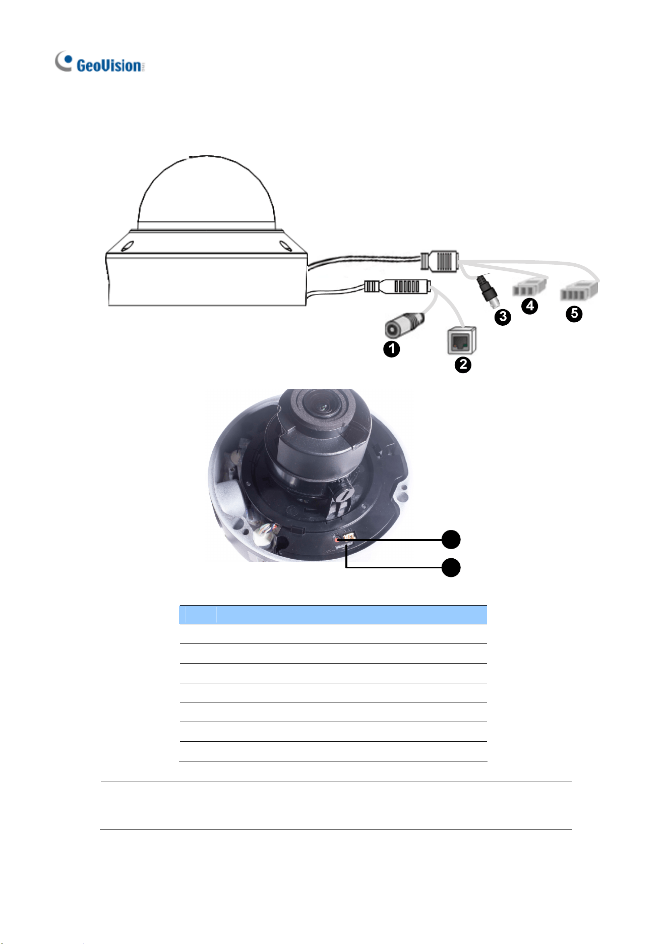
1.2.2 GV-EBD4711 / 8711
No. Description
1 Bottom ring
2 Housing
3 Microphone
4 Lens
5 Power connector (DC 12 V)
6 Ethernet connector / PoE
7 Micro SD card slot and default button compartment
8 Default button
9 Micro SD card slot
Note: If the default button doesn’t respond after pressing for 15 seconds, reboot the
camera and try again within 10 minutes of rebooting.
GV-EBD Series
5
1
1.3 Installation
The Target Eyeball Dome is designed for outdoors. With the standard package, you
can install the camera on the ceiling. Or you can purchase optional mounting
accessories to mount the dome on a wall.
Below are the instructions for Ceiling Mount. There are two kinds of Ceiling Mount:
Concealed Installation and Open Installation. In Concealed Installation, the cables
are hidden in the ceiling. In Open Installation, the cables are led out from the open slot
on t he bottom ring.
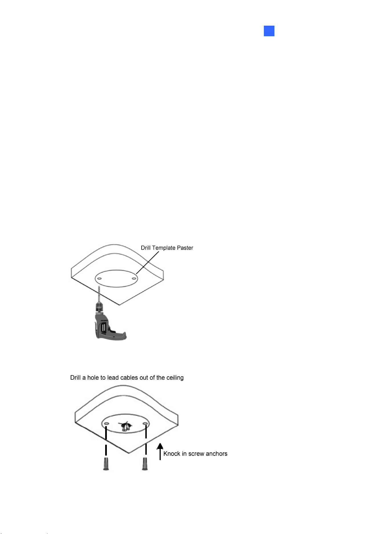
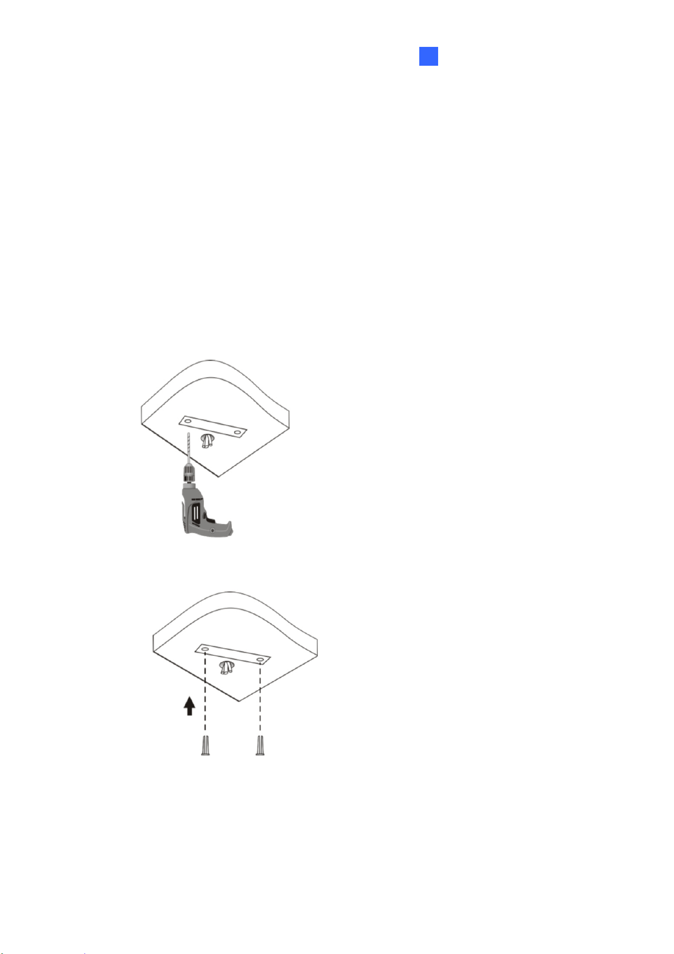
1.3.1 GV-EBD2702 / 4700 / 8700 Installation
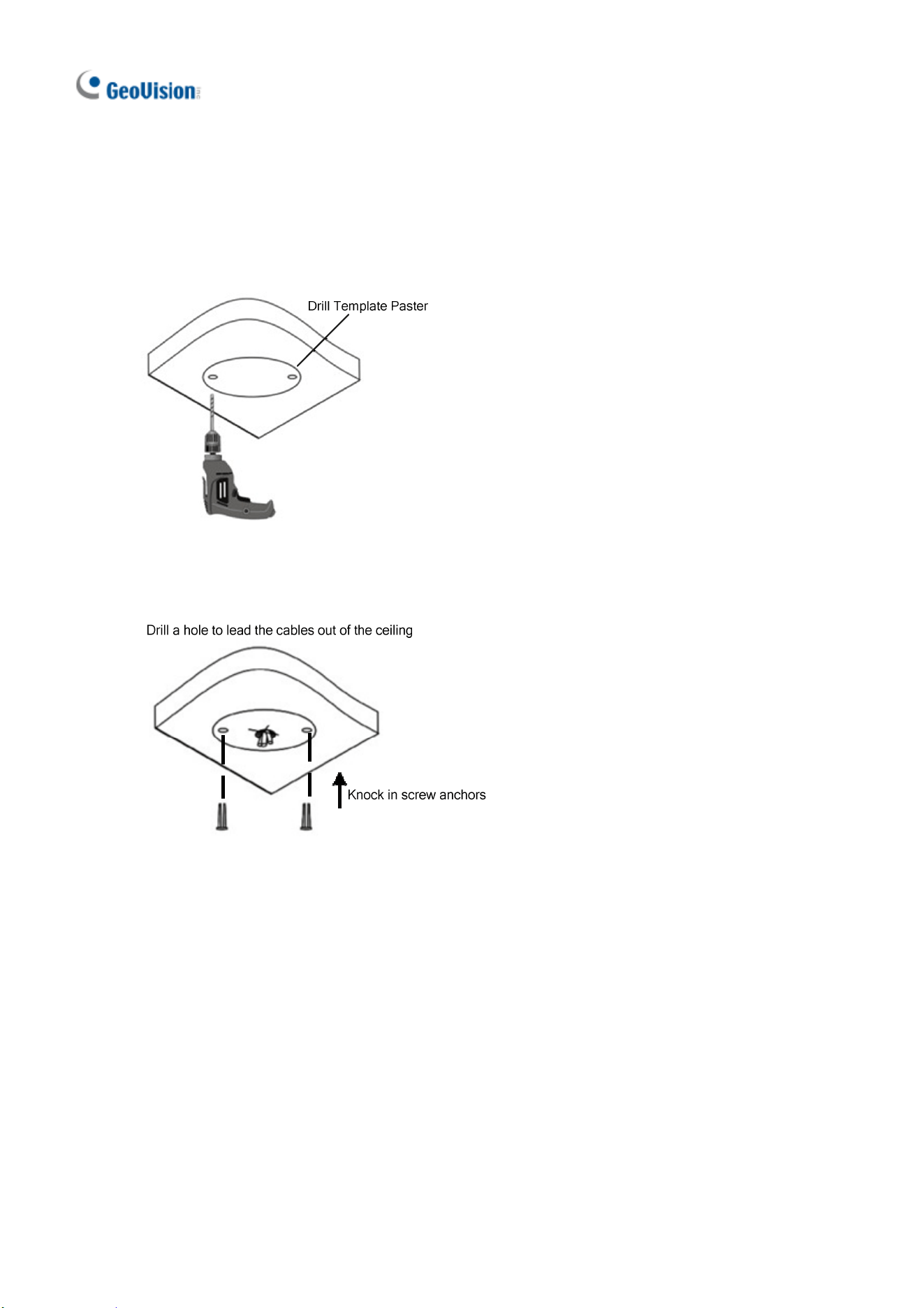
For Concealed Installation
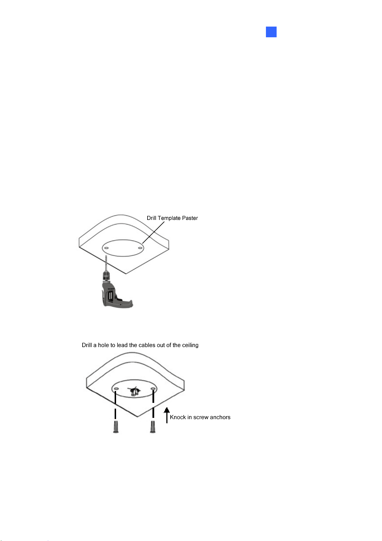
1. Stick the drill template paster to the ceiling and drill three holes according to the
drill template.
2. Insert the screw anchors.
8
6
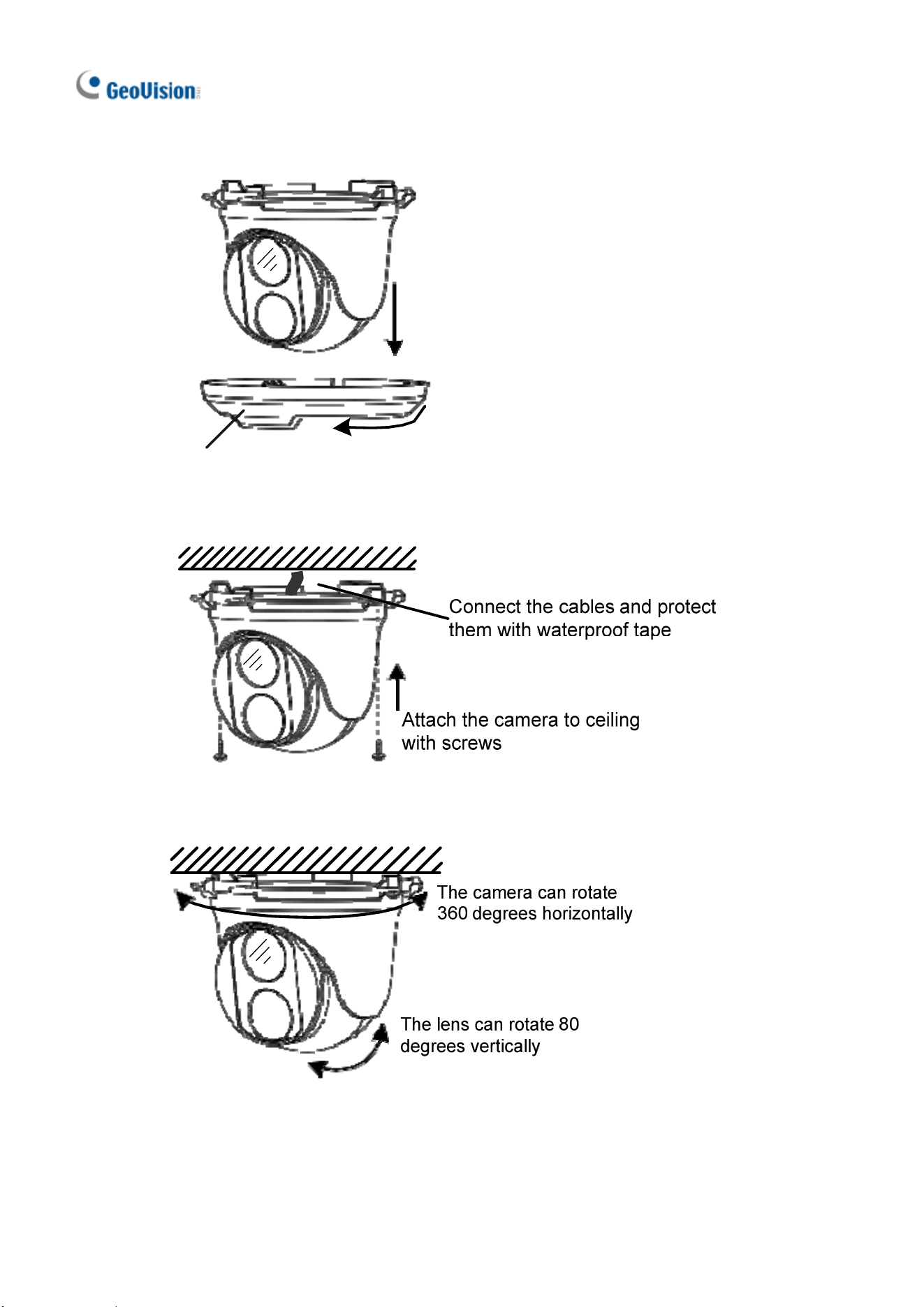
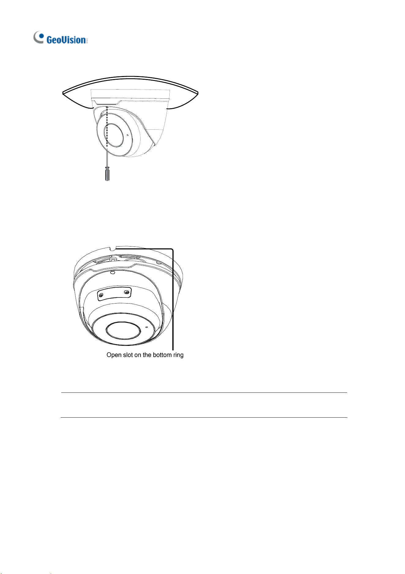
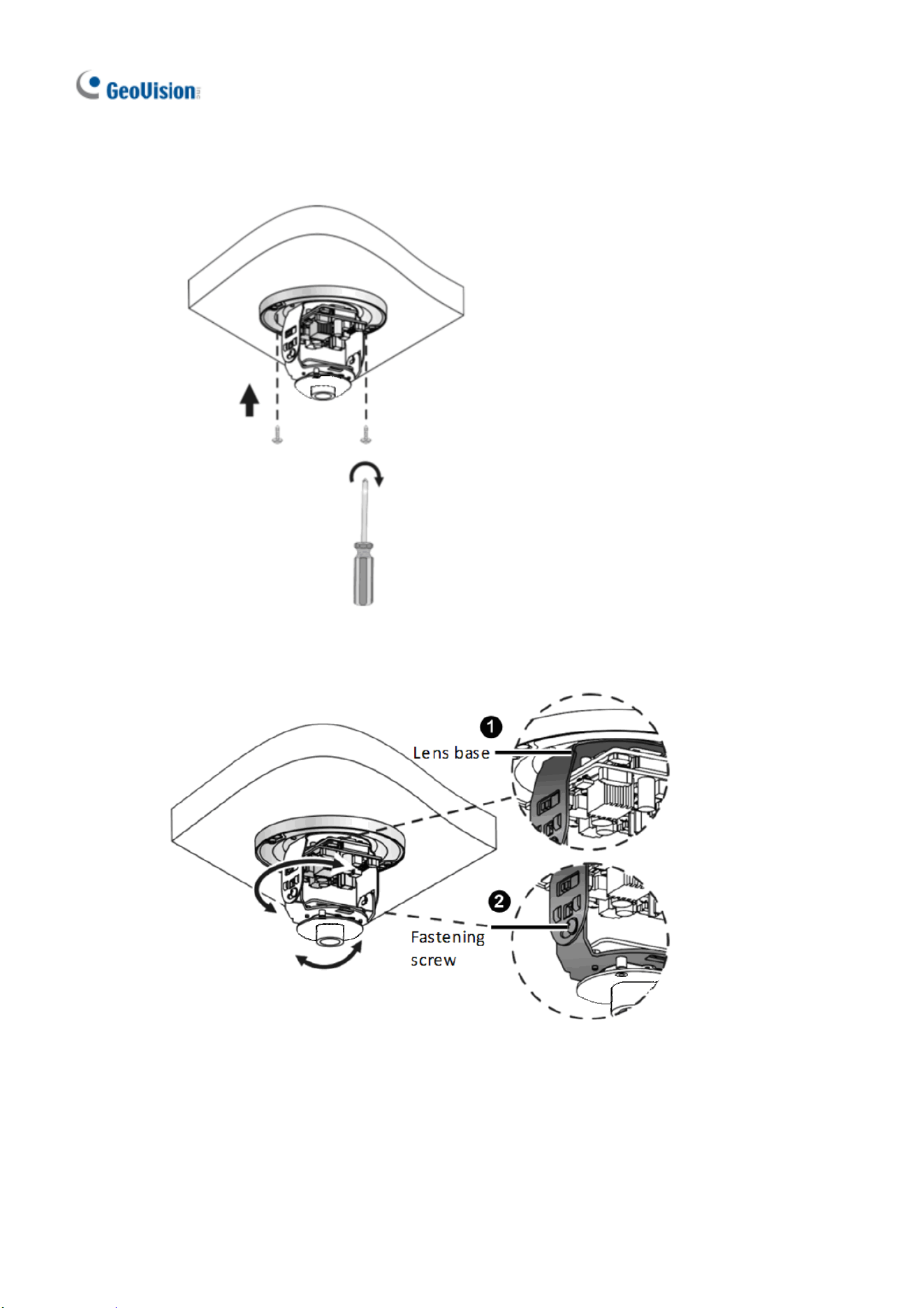
3. Remove the bottom ring by turning it anticlockwise.
Bottom Ring
4. Connect the cables and secure the camera.
5. Adjust the monitoring direction.
GV-EBD Series
7
1
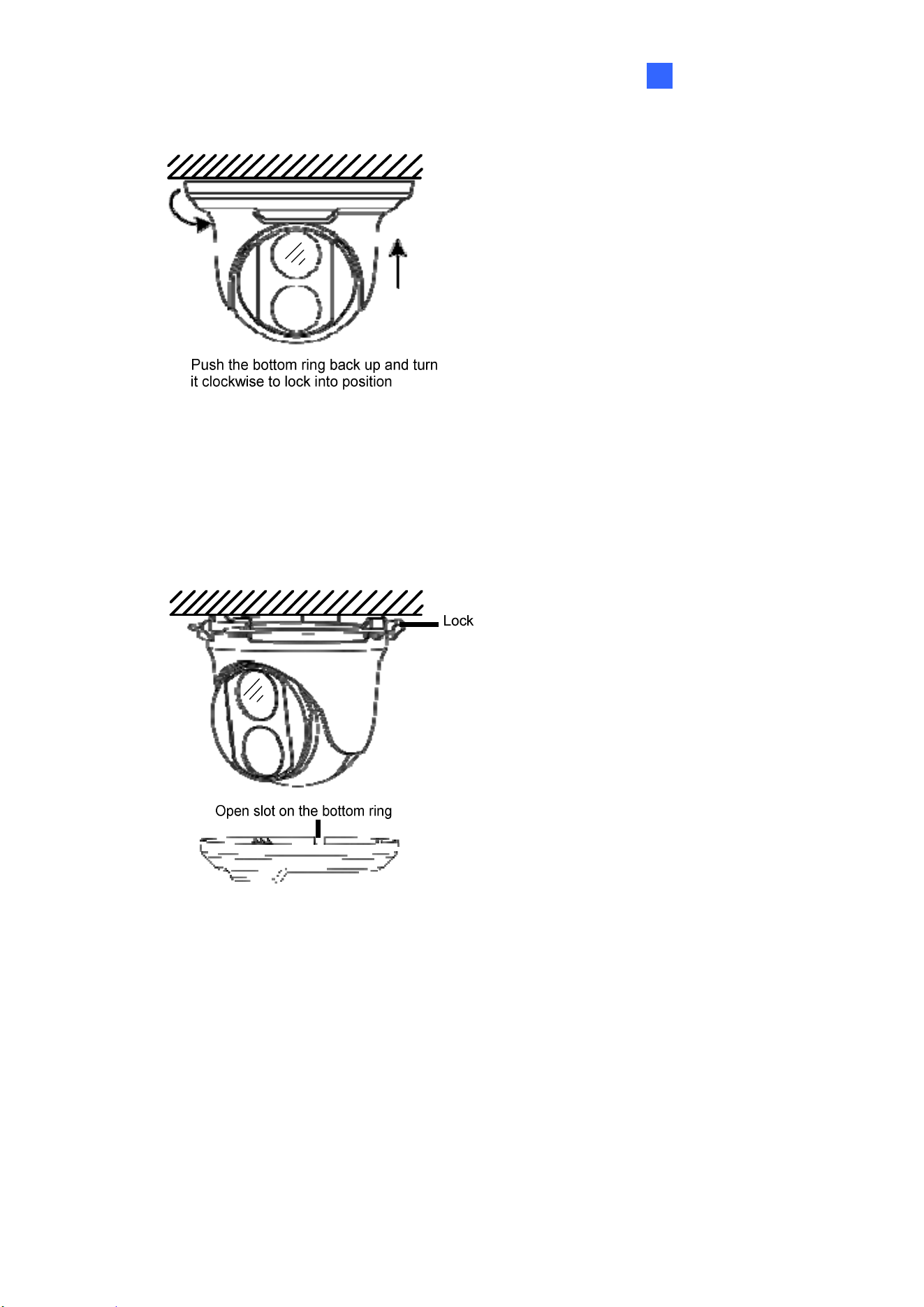
6. Mount the bottom ring.
For Open Installation
Lead the cables out from the open slot on the bottom ring before screwing the camera
to the ceiling as shown in step 4 of Conceal Installation.
8
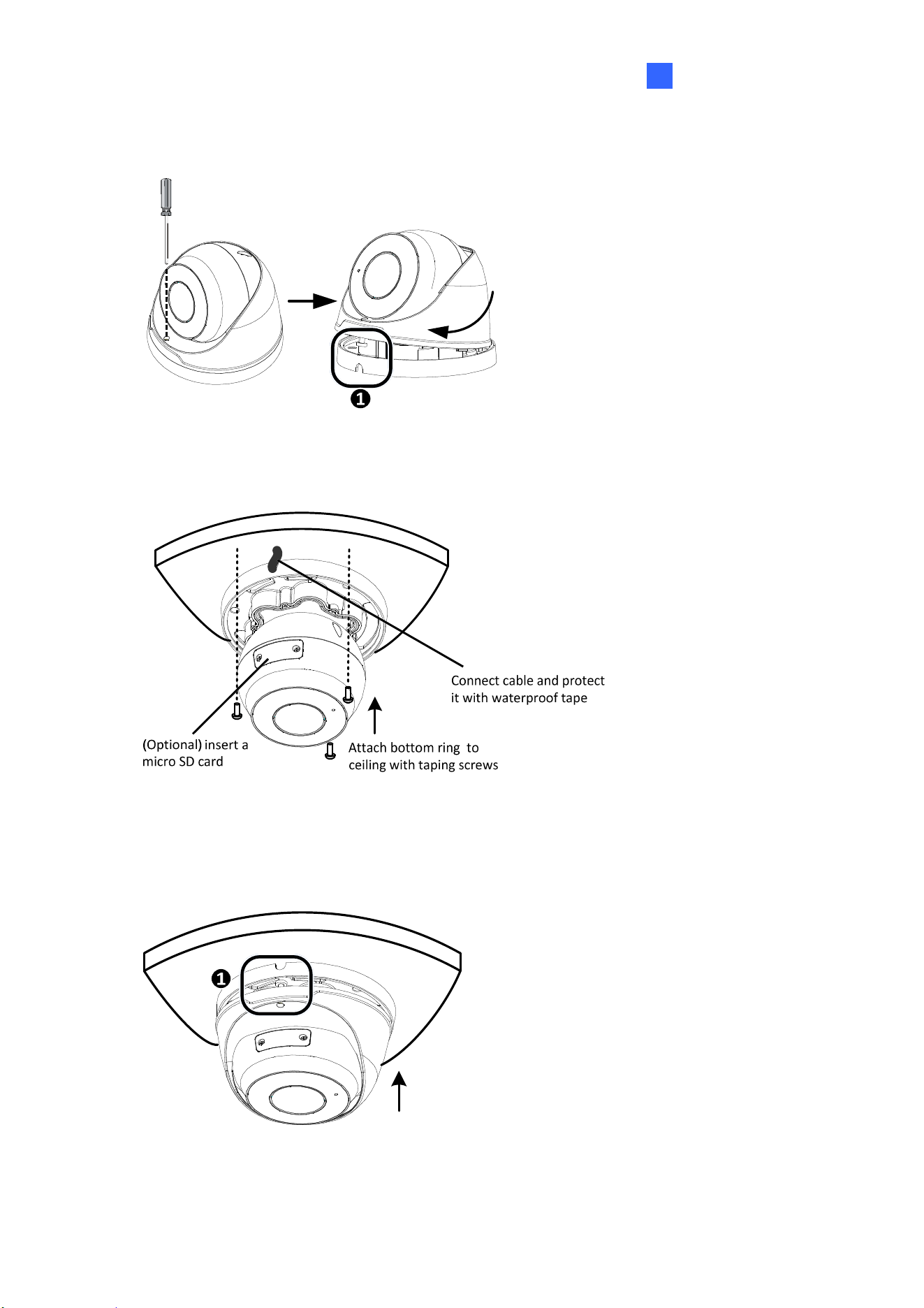
1.3.2 GV-EBD4711 / 8711 Installation
For Concealed Installation
1. Stick the drill template paster to the ceiling and drill three holes according to the
drill template.
2. Insert the screw anchors.
GV-EBD Series
9
1
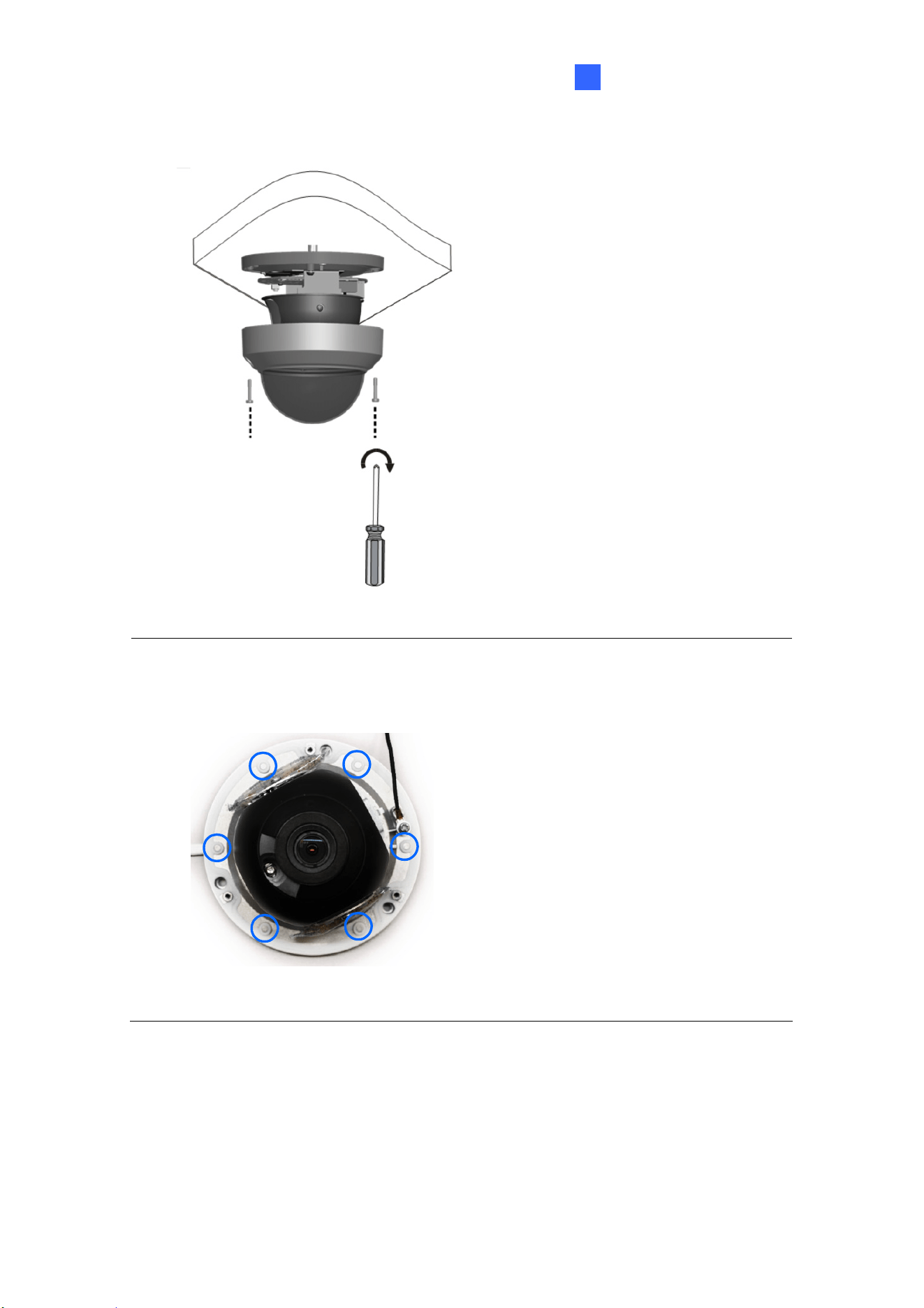
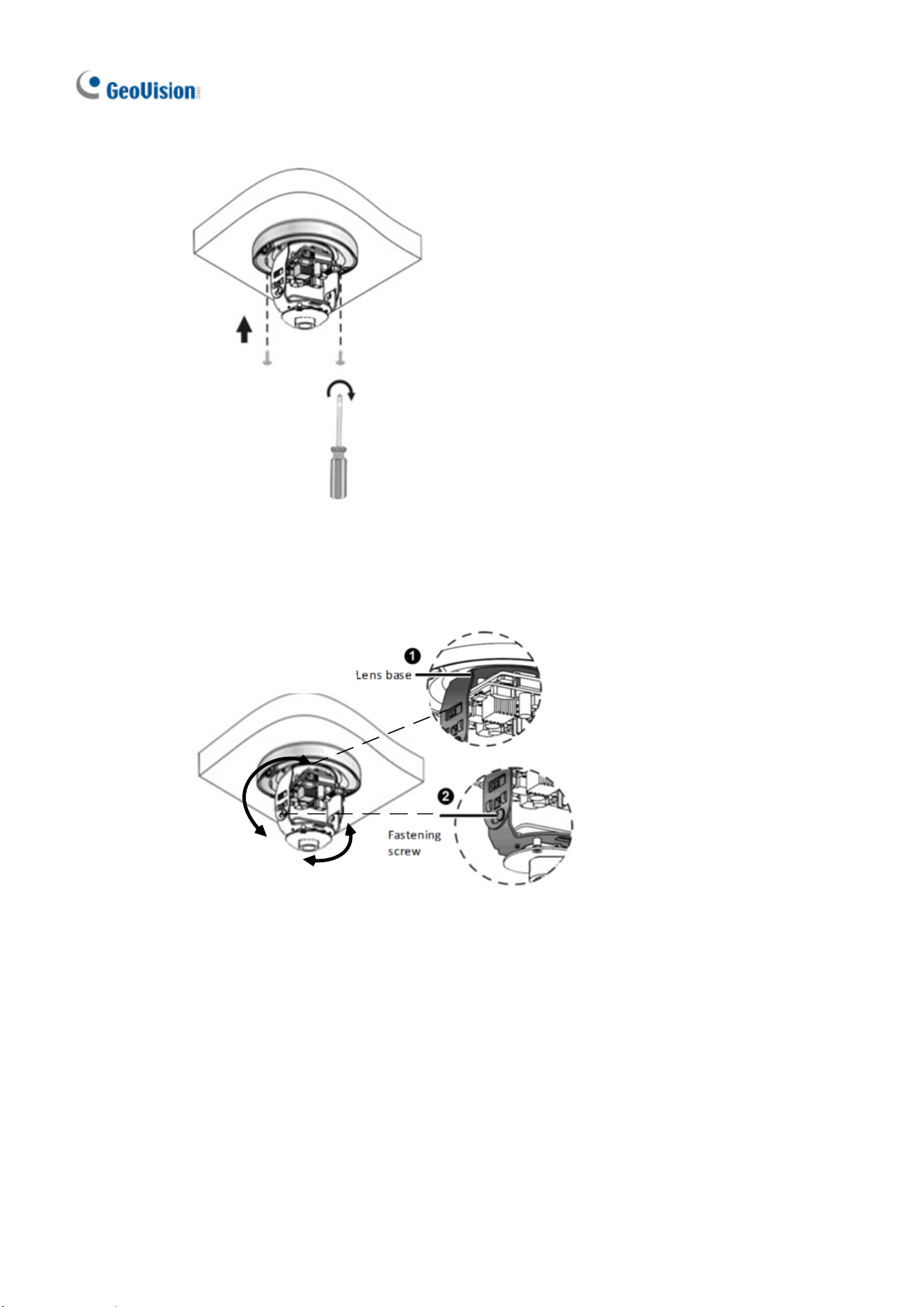
3. Loosen the fixing screw and remove the housing by turning it to the position as
shown.
4. Secure the bottom ring to the ceiling with 3 supplied screws and connect the
cable.
5. Mount the housing by adjusting to the position as shown and press and turn to
anywhere but .
10
6. Adjust the monitoring direction. Then tighten the screw.
For Open Installation
Lead the cables out from the open slot on the bottom ring before screwing the camera
to the ceiling as shown in step 5 of Concealed Installation.
Note: You can optionally purchase GV-Mount211 or GV-Mount212 for Wall Bracket
Mount. For details, see its User’s Manual.
11
Camera Type Model No.
GV-ABL2701 Series (IP66)
GV-ABL2702 (IP67 + IK10)
GV-ABL2703 Series (IP67)
GV-ABL4701 Series (IP66)
GV-ABL4703 (IP67)
GV-ABL4712 (IP67)
GV-ABL8712 (IP67 + IK10)
GV-TBL4710 (IP67 + IK10)
Bullet IP Camera
GV-TBL8710 (IP67 + IK10)
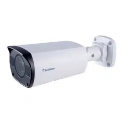
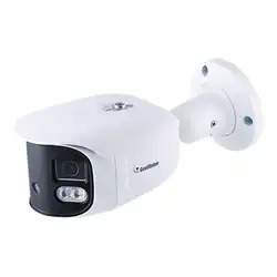
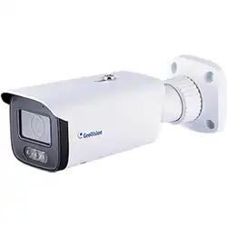
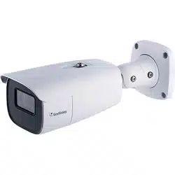
2. GV-ABL / TBL Series
12
2.1 Packing List
Bullet IP Camera
Waterproof Rubber Set
Screw Kit
Drill Template Paster
Download Guide Warranty Card
GV-ABL Series
13
2
2.2 Overview
2.2.1 GV-ABL2701 / 2703 / 4701 / 4703
No. Description
1 Power connector (DC 12 V)
2 Ethernet connector / PoE
Load Default Button (for GV-ABL2703 / 4703 only)
No. Description
1 Load Default button
2 Placement screw
Note:
1. Do not loosen or remove the placement screw under any circumstances.
2. If the default button doesn’t respond after pressing for 15 seconds, reboot the
camera and try again within 10 minutes of rebooting.
14
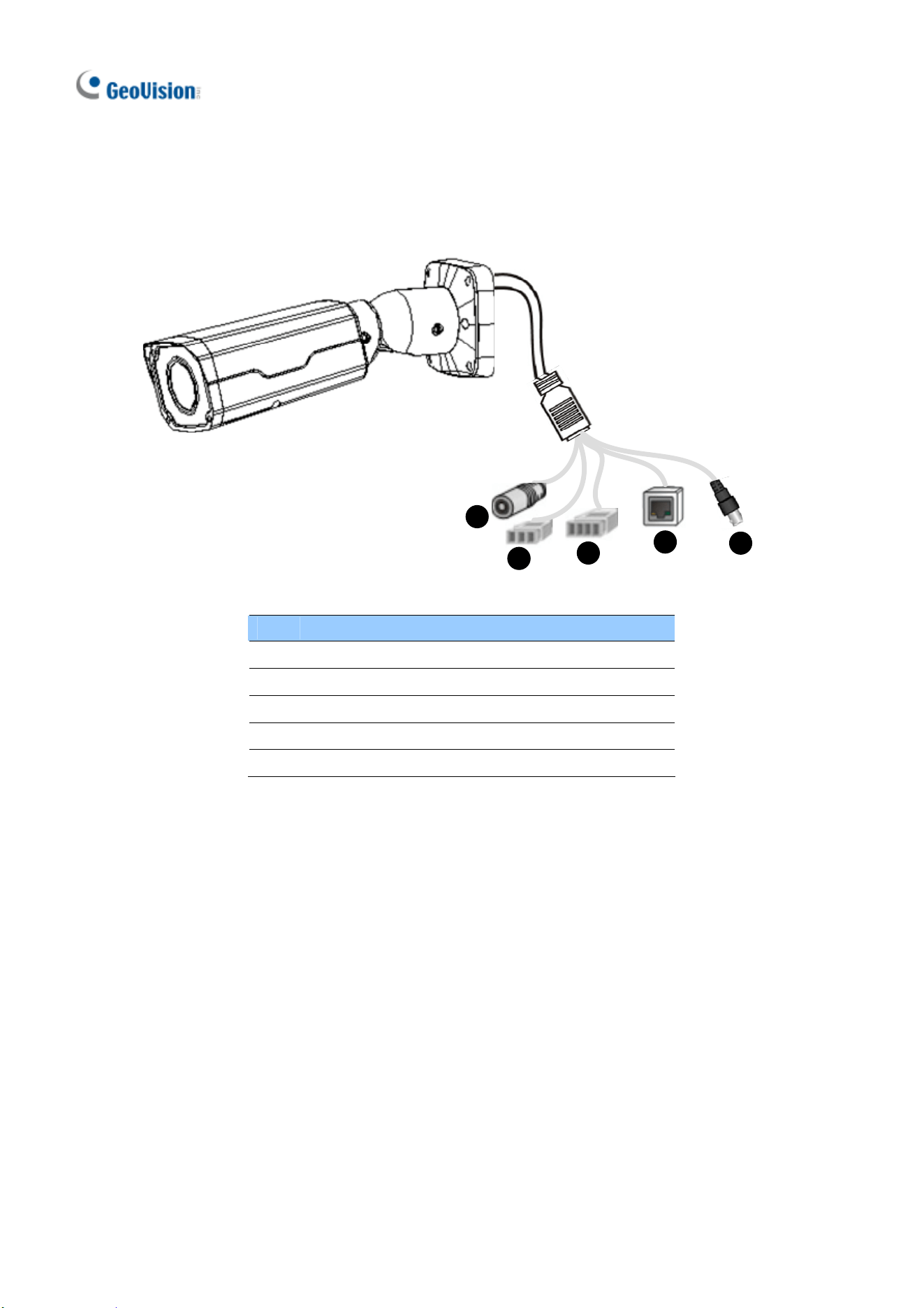
2.2.2 GV-ABL2702 / 4712 / 8712 / TBL Series
1
2
3
4
5
No. Description
1 Power connector (DC 12 V)
2 Audio input / Audio output / GND
3 Alarm input (IN, GND) / Alarm output (N,P)
4 Ethernet connector / PoE
5 Video Output (GV-ABL8712 / TBL8710 Only)
GV-ABL Series
15
2
2.3 Installation
The Bullet IP Camera is designed for outdoors. With the standard package, you can
install the camera on the wall or ceiling. Or, you can purchase optional mounting
accessories to mount your camera on a wall.
Below are the instructions for Wall Mount. There are two kinds of Wall Mount:
Concealed Installation and Open Installation. In Concealed Installation, the cables
are hidden in the wall. In Open Installation, the cables are led out from the open slot
on the base.
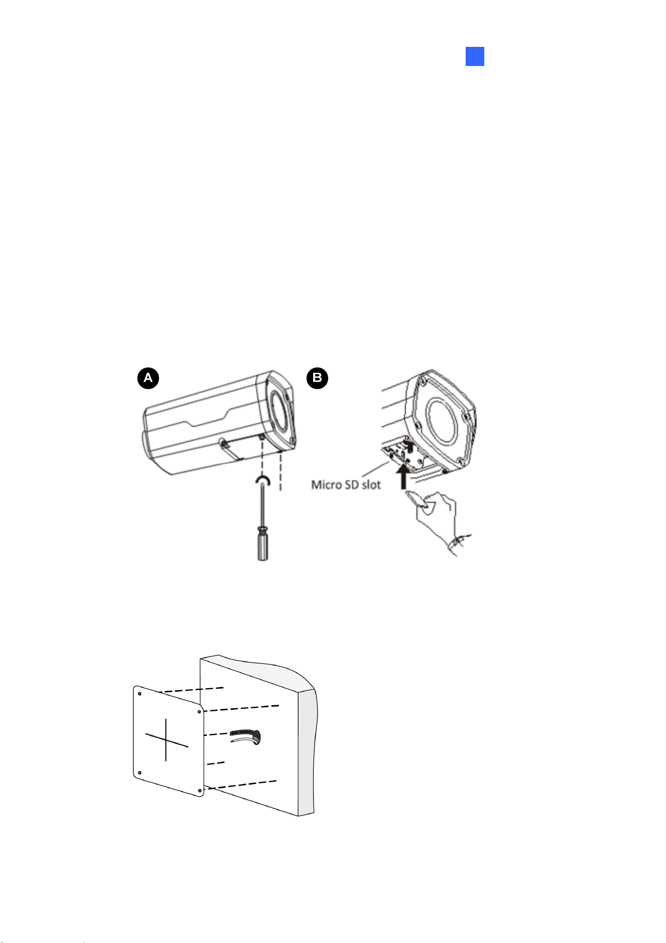
For Concealed Installation
1. For GV-ABL2702 / 4712 / 8712 / TBL Series, optionally loosen the two screws at
the bottom of the camera to insert a SD card.
2. Stick the drill template paster to the wall and align the cross center to the hole in
the wall.
3. Lead the cables across the hole on the wall.
16
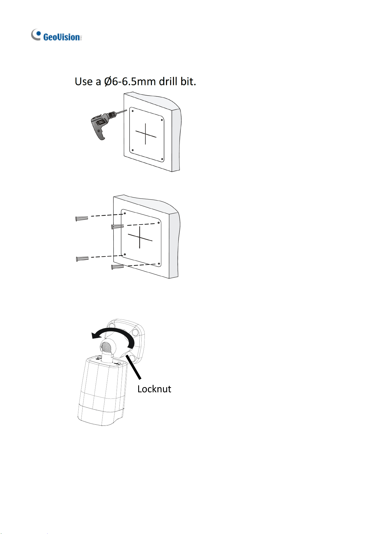
4. Drill four 30-mm deep holes according to the drill template.
5. Insert the screw anchors.
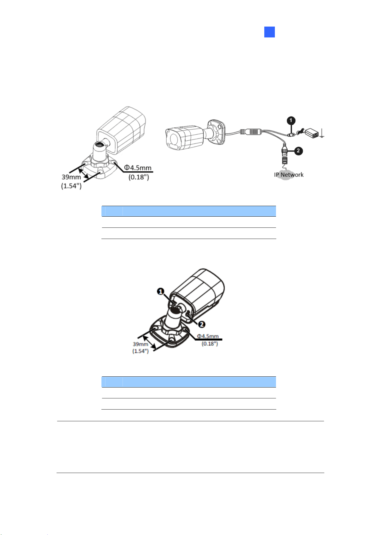
6. Screw the locknut and loosen the universal joint before attaching the camera to
the wall.
GV-ABL Series
17
2
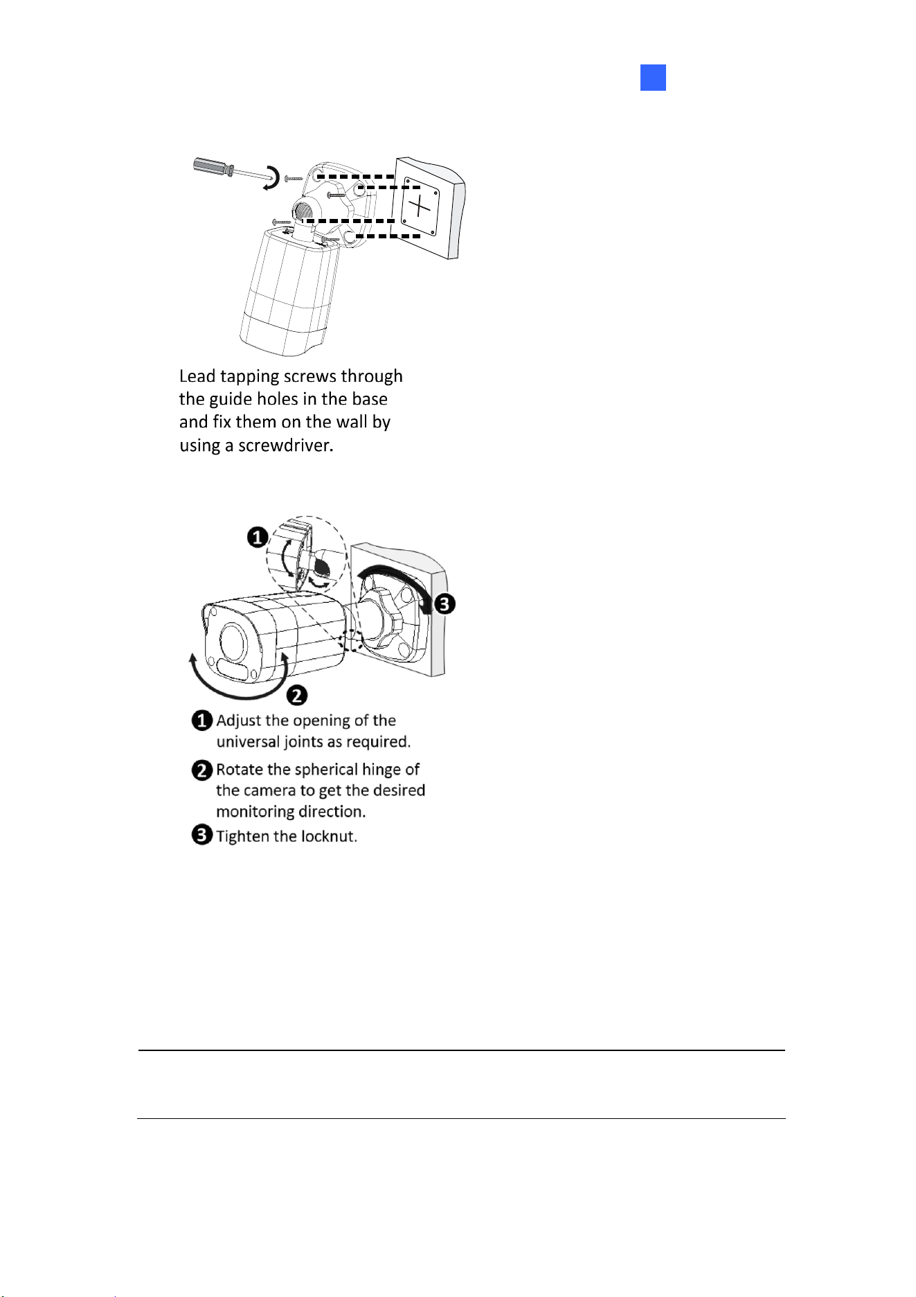
7. Secure the camera to the wall and connect all cables.
8. Adjust the monitoring direction.
For Open Installation
Lead the cables out from the open slot on the base before screwing the camera to the
wall as shown in step 6 in For Concealed Installation.
Note: You can optionally purchase GV-Mount502 for Wall Bracket Mount. For
details, see its User’s Manual.
18
3. GV-ADR / TDR Series
Camera Type Model No.
GV-ADR2701 (IP66)
GV-ADR2702 (IP67 + IK10)
GV-ADR4701 (IP66 + IK10)
GV-ADR4702 (IP67 + IK10)
GV-TDR2700 (IP67 + IK10)
Mini Fixed Rugged IP Dome
GV-TDR4700 (IP67 + IK10)
GV-ADR / TDR Series
19
3
3.1 Packing List
GV-ADR2701 / 2702 / 4701 / 4702 /
TDR2700 / 4700 IR Mini Fixed Rugged IP
Dome
Waterproof Rubber Set
Screw Kit
Drill Template Paster
Download Guide
Warranty Card

20
3.2 Overview
No. Description
1 Ethernet connector / PoE
2 Power connector (DC 12 V)
3 Transparent Dome Cover
4
For GV-TDR2700 / 4700 only, see the table
below.
Wire Definition
Wire Definition
Green Audio in
Blue GND
Yellow Alarm Out
White Alarm Out
Orange Alarm Input
Blue GND
Brown Audio in
Blue GND
Gray Audio Out
Purple GND
GV-ADR / TDR Series
21
3
3.3 Installation
The IR Mini Fixed Rugged IP Dome is designed for outdoors. With the standard
package, you can install the camera on the ceiling.
Below are the instructions for Ceiling Mount. There are two kinds of Ceiling Mount:
Concealed Installation and Open Installation. In Concealed Installation, the cables
are hidden in the ceiling. In Open Installation, the cables are led out from the open slot
on the camera base.
For Concealed Installation
1. Stick the drill template paster to the ceiling and drill 30-mm deep holes according
to the drill template.
2. Insert the screw anchors.
22
3. Unscrew the transparent dome cover with the supplied torx wrench.
4. Connect the cables and secure the camera.
5. Adjust the monitoring direction and tighten the screws after vertically adjusting the lens.
GV-ADR / TDR Series
23
3
6. Secure the transparent dome cover with the supplied torx wrench.
Note: Before securing the transparent dome cover, make sure the waterproof rubber
strip is tightly held by the six retainers on the bottom ring.
For Open Installation
Lead the cables out from the open slot on the camera base before screwing the
camera to the ceiling as shown in step 4 in For Concealed Installation.
24
4. GV-AVD / TVD Series
Camera Name Model No.
GV-AVD2700 (IP67 + IK10)
GV-AVD4710 (IP67 + IK10)
GV-AVD8710 (IP67 + IK10)
GV-TVD4710 (IP67 + IK10)
Vandal Proof IP Dome
GV-TVD8710 (IP67 + IK10)
GV-AVD Series
25
4
4.1 Packing List
IR Vandal Proof IP Dome
Waterproof Rubber Set
Screw Kit
Drill Template Paster
Torx Wrench
Download Guide
Warranty Card
26
4.2 Overview
6
7
No. Description
1 Power connector (DC 12 V)
2 Ethernet connector / PoE
3 Video Output
4 Audio input / Audio output / GND
5 Alarm input (IN,GND) / Alarm output (N,P)
6 Default button
7 Micro SD card slot
Note: If the default button doesn’t respond after pressing for 15 seconds, reboot the
camera and try again within 10 minutes of rebooting.
GV-AVD Series
27
4
4.3 Installation
The Target Vandal Proof Dome is designed for outdoors. With the standard package,
you can install the camera on the ceiling. Alternatively you can purchase optional
mounting accessories to mount the camera on a wall.
Below are the instructions for Ceiling Mount. There are two kinds of Ceiling Mount:
Concealed Installation and Open Installation. In Concealed Installation, the cables
are hidden in the ceiling. In Open Installation, the cables are led out from the open slot
on the camera base.
For Concealed Installation
1. Stick the drill template paster to the ceiling, and then drill three holes according to
the drill template.
2. Insert the screw anchors.
3. Unscrew the transparent dome cover with the supplied torx wrench.
28
4. Connect the camera cables and secure the camera.
5. Insert a SD card into the slot.
6. Adjust the monitoring direction and tighten the screws after vertically adjusting the
lens.
7. Secure the transparent dome cover with the supplied torx wrench.
For Open Installation
Lead the cables out from the open slot on the camera base before screwing the
camera to the ceiling as shown in Step 4.
29
5. Waterproofing the Cable
Waterproof the Ethernet cable by using the supplied waterproof rubber set.
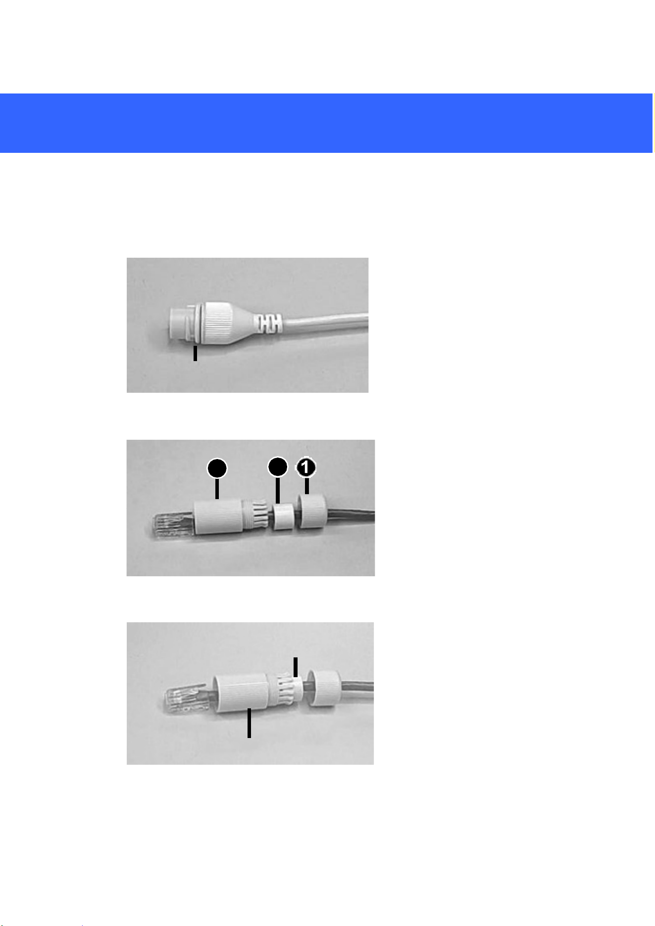
1. Attach the seal ring to the RJ-45 plug.
Seal ring
2. Insert the waterproof components through the Ethernet cable as shown below.
3
2
Insertinorder
3. Insert the cylindrical waterproof ring into waterproof bolt.
Cylindricalwaterproofring
Water
p
roofbolt
30
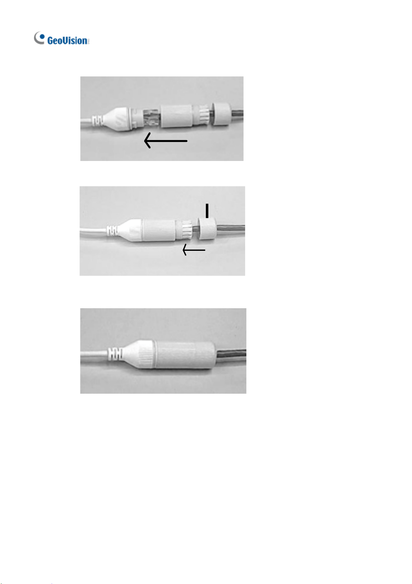
4. Insert the cable into the RJ-45 plug and screw the waterproof bolt in.
5. Screw in the waterproof bolt lid.
Bolt lid
6. Finish the waterproof installation.
31
6. Accessing the Camera
6.1 System Requirements
Once installed, your camera is accessible over the network. Make sure your PC has
good network connection and meet the following requirements:
CPU Intel Core i5-4670, 3.40 GHz
Memory DDR3 8 GB RAM
On Board Graphics Intel HD Graphics 4600 (Versions of driver from year 2014 or
later required)
Web Browsers Internet Explorer 11.0 or above
Google Chrome
Microsoft Edge
Mozilla Firefox
Safari
Note:
1. Some functions are not available on non-IE browsers, e.g. Local Settings (see
3.1.2 Local Settings in the User’s Manual) is not supported by Google Chrome.
2. Only H.264 codec is supported for live view on non-IE browsers.
32
6.2 Looking Up the Dynamic IP Address
By default, when the camera is connected to LAN a with DHCP server, it is
automatically assigned with a dynamic IP address. Follow the steps below to look up
its IP address.
Note: The computer you use to configure the IP address must be under the same
LAN as your camera.
1. Download and install the GV-IP Device Utility program from the company
website
.
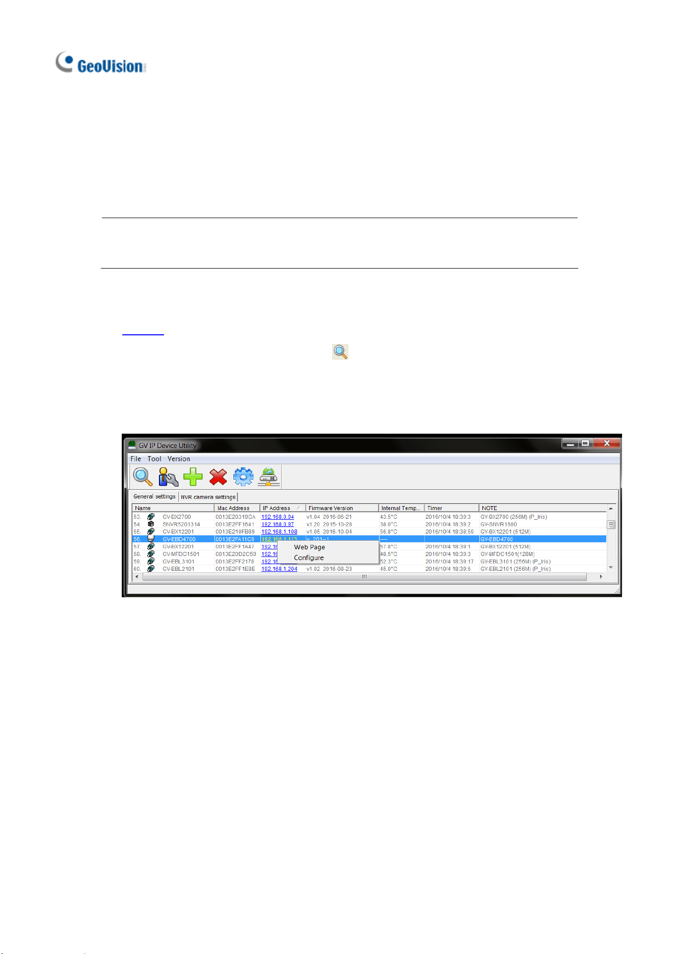
2. On the GV-IP Utility window, click the
button to search for the IP devices
connected in the same LAN. Click the Name or Mac Address column to sort.
3. Find the camera with its Mac Address, click on its IP address and select Web
Page.
Accessing the Camera
33
6
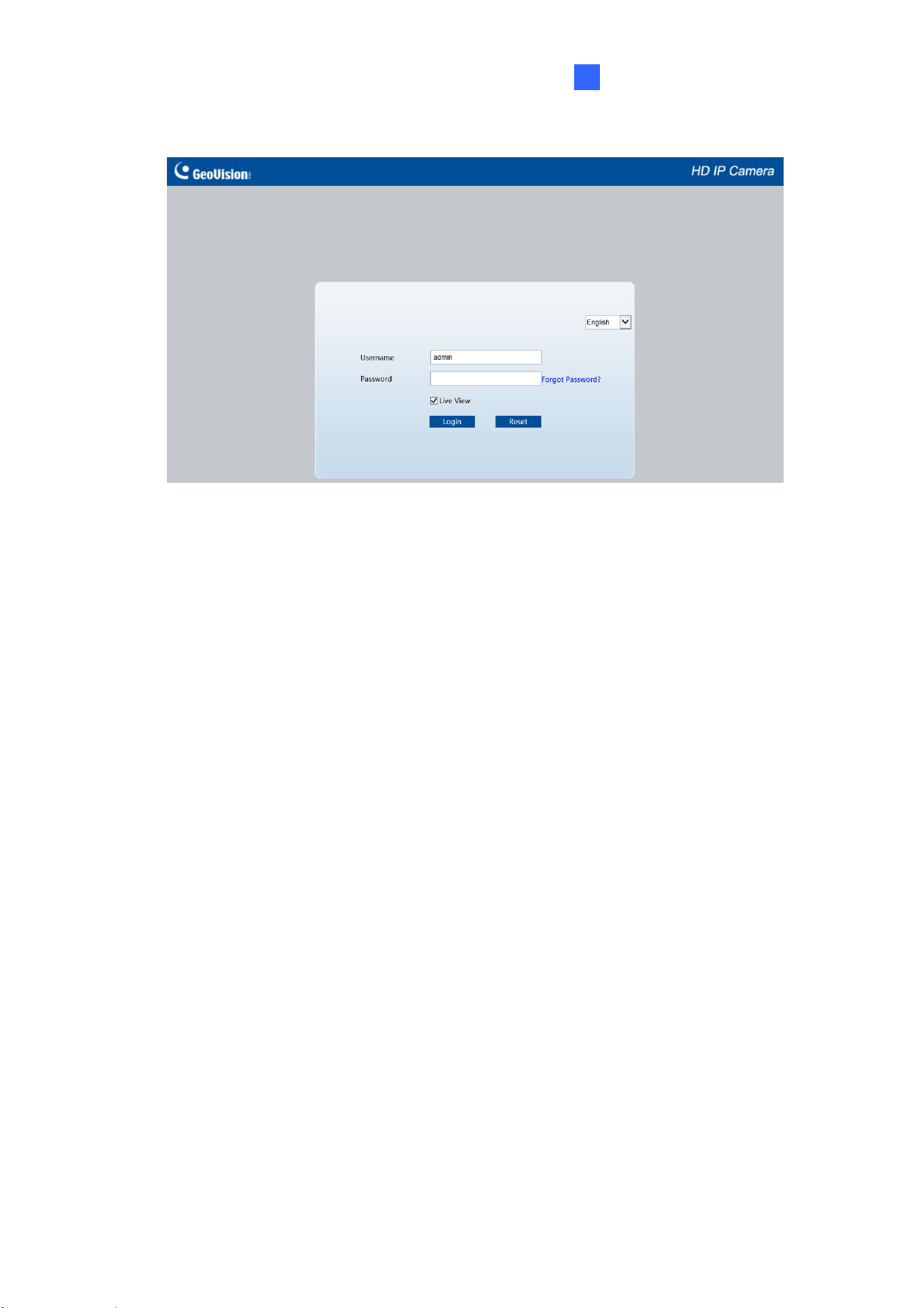
4. The login page appears.
5. For first-time accessing of the Web interface, download and install the plug-in.
6. Type the default ID and password admin and click Login.
34
6.3 Configuring the IP Address
If the camera is connected to a LAN without DHCP server, the default IP address will
be 192.168.0.10. Follow the steps below to modify the IP address to avoid IP conflict
with other GV-IP devices on the same LAN.
1. Open your Web browser, and type the default IP address http://192.168.0.10.
2. Type the default username and password admin. Click Login.
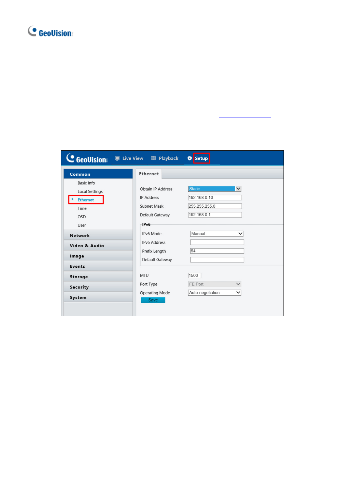
3. Click Setup, select Common in the left menu and select Ethernet.
4. Select Static IP from the IP Obtain Mode drop-down list.
5. Enter the IP address, subnet mask, and default gateway address. Make sure that
the IP address of the camera is unique in the network.
6. Click Save.
35
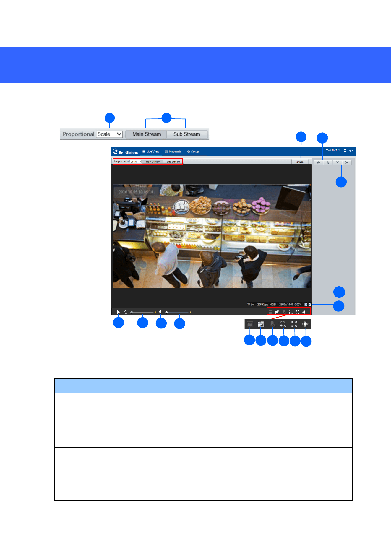
7. The Web Interface
Once you log in the Web interface, you will see the live view as shown below.
1 2
4
16
15
5
17
3
6
7
8
9
10
11 12
13
14
15
No. Name Function
1 Proportional
Set the display ratio of the image.
Scale: display images by 16:9.
Stretch: display images by window size.
Original: display images in its original size.
2 Live Stream
Select a live video stream: main stream, sub stream or third
stream (when enabled).
3 Image
Open the image setting page. – See 3.4.1 Image in the User’s
Manual.
36
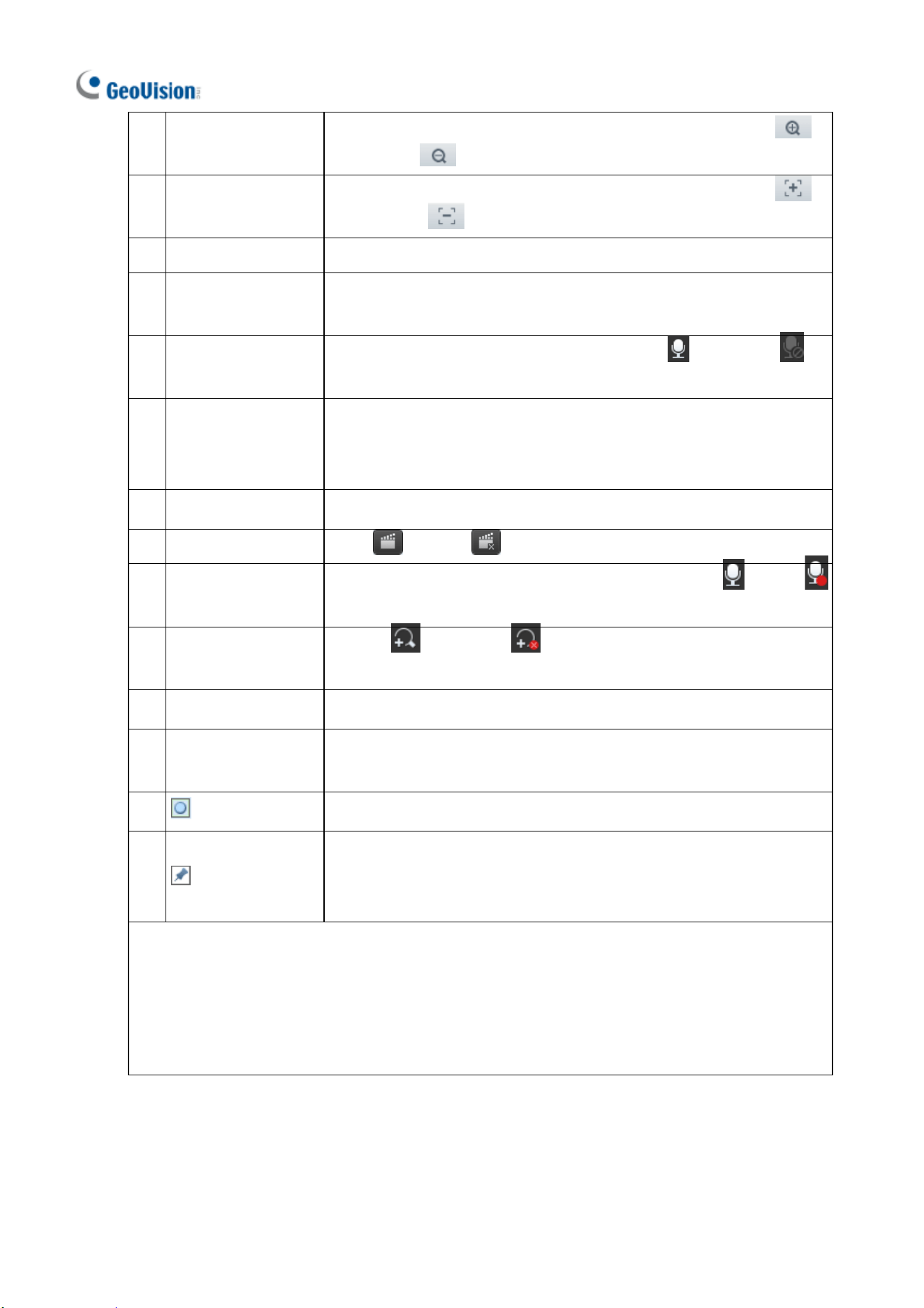
4 Zoom +/-
Only for models with motorized varifocal lens, increase
or decrease
the camera’s optical zoom.
5 Focus +/-
Only for models with motorized varifocal lens, increase
or decrease
the camera focus.
6 Play/Stop Play or stop live video.
7 Video Volume
Only for audio-supporting models, adjust the audio output
volume on the PC.
8 Microphone
Only for audio-supporting models, enable
or disable
microphone.
9 Microphone Volume
Only for audio-supporting models, adjust the microphone
volume on the PC during audio communication between the PC
and the camera.
10 Snapshot Take a snapshot of the current image displayed on the PC.
11 Local Recording Start or stop local recording.
12 Two-way Audio
Only for two-way-audio-supporting models, start
or stop
two-way audio.
13 Digital Zoom
Enable
or disable digital zoom. – See 2.2.1.1 Digital
Zoom in the User’s Manual.
14 Full Screen Display in full screen mode.
15 Control Panel
Only for models with motorized varifocal lens, hide or show the
camera’s optical zoom and focus functions.
16 Reset the packet loss rate to zero.
17
Click to always display packet loss rate and bit rate information at
the bottom. Click again to restore to only displaying the information
for 3 seconds when the mouse cursor is moved onto the live view.
Note:
1. The paths for saving snapshots and local recordings are set in Local Settings. See 3.1.2
Local Settings in the User’s Manual.
2. The No. 16 and 17 buttons will appear on the floating toolbar when you move the mouse
cursor onto the live view.
37
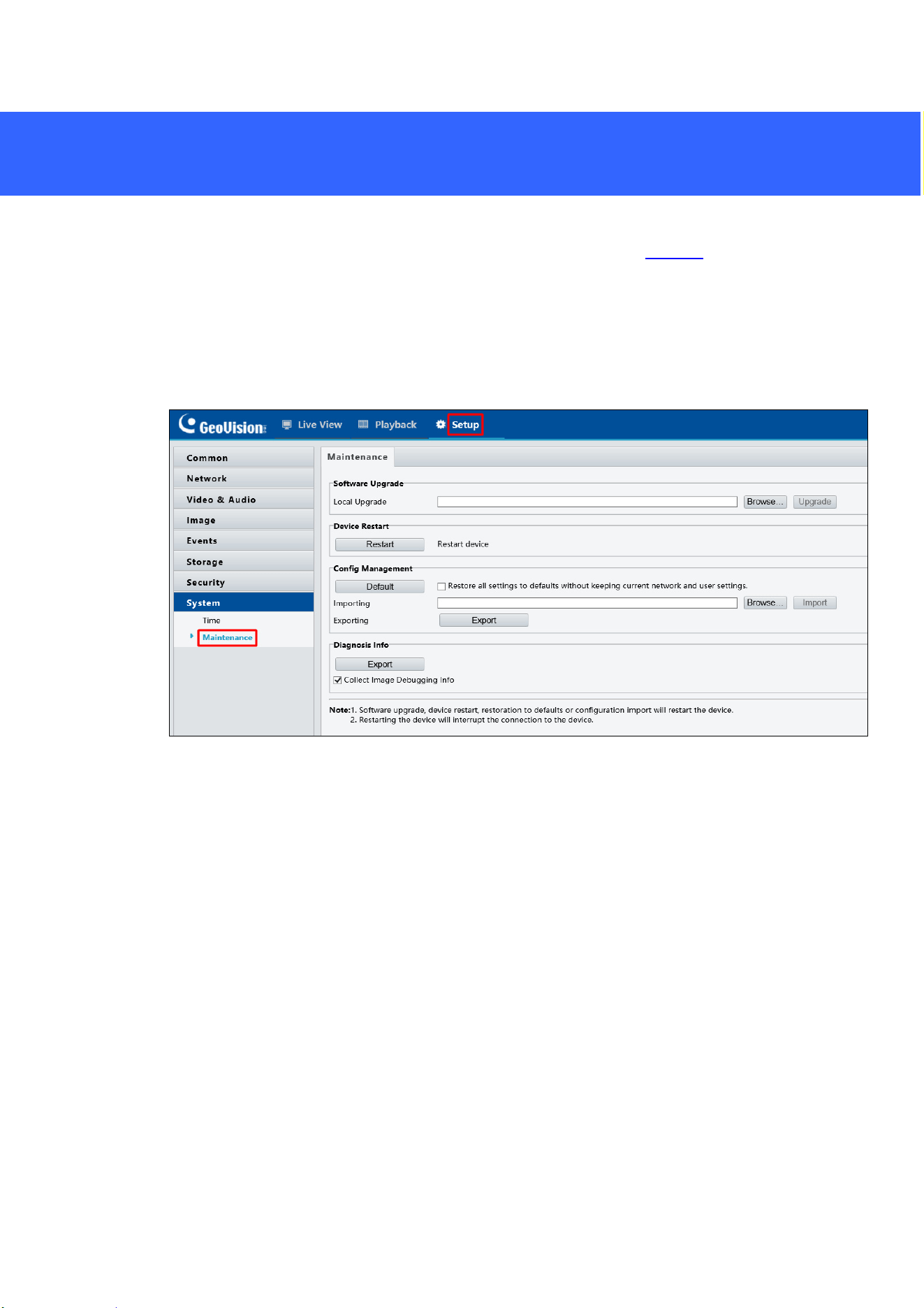
8. Upgrading System Firmware
GeoVision periodically releases updated firmware on the company website. To load
the new firmware into the camera, follow the instructions below.
1. At the top of the Web interface, click Setup.
2. In the left menu, select System and select Maintenance. This page appears.
3. Click Browse under Software Upgrade to locate the firmware file (.zip) saved at your
local computer.
4. Click Upgrade to process the upgrade.
38
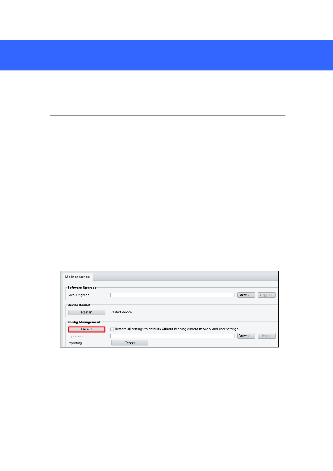
9. Restoring to Factory Default
If for any reason the camera is not responding correctly, you can restore the camera
back to its factory default settings using the Web interface or the Default Button.
Note:
1. Only GV-EBD4711 / 8711, GV-ABL2703 series / 4703, GV-AVD2700 / 4710 /
8710 and GV-TVD4710 / 8710 support a default button. For the default button of
GV-ABL2703 series / 4703, see Load Default Button (for GV-ABL2703 / 4703
only) (No. 1), in 2.2.1 GV-ABL2701 / 2703 / 4701 / 4703. For GV-EBD4711 /
8711, see 1.2.2 GV-EBD4711 / 8711 (No.8). For GV-AVD2700 / 4710 / 8710 and
GV-TVD4710 / 8710, see 4.2 Overview (No.6).
2. If the default button doesn’t work after pressing for 15 seconds, reboot the
camera and try again within 10 minutes of rebooting.
1. In the Web interface, click Setup.
2. In the left menu, select System and select Maintenance.
3. Under the Config Management section, click Default.